FD869
21DE00
COPYRIGHT
Page 1 of 6
FITTING INSTRUCTIONS FOR
TS ASTRA HATCH BACK
1000kg TOW BAR PACKAGE
Part Number 92079514
G37-01a
HOLDEN SERVICE PARTS OPERATIONS
Reproduction in whole or part
prohibited without written approval
Division of HOLDEN Ltd ACN 006 893 232
TOOLS REQUIRED:
TORX HEAD SCREW DRIVER (TORX BIT No. 20)
SCRAPER (FOR DEADENER REMOVAL)
HOT AIR GUN
DRILL
DRILL BIT, 8.0mm
METAL PRIMER
SILICONE OR BUTYL SEALER
SOCKET WRENCH
TORQUE WRENCH
SOCKETS: 10.0mm
16.0mm
TS ASTRA HATCH BACK, 1000kg TOWBAR PACKAGE
FITTING INSTRUCTIONS
G37-02a
Page 2 of 6
HOLDEN SERVICE PARTS OPERATIONS
Reproduction in whole or part
prohibited without written approval
Division of HOLDEN Ltd ACN 006 893 232
COPYRIGHT
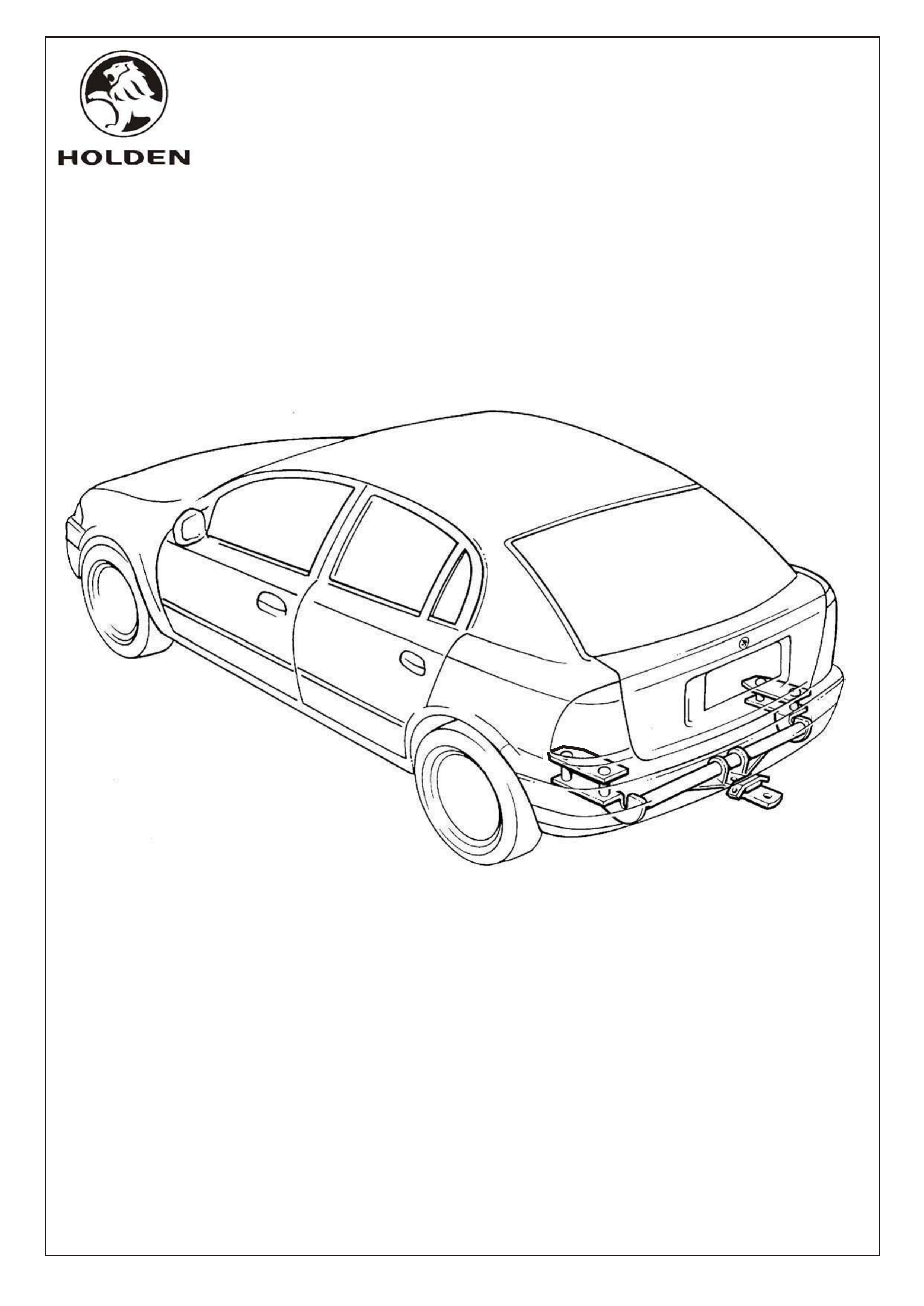
1. Open rear hatch, remove rear parcel shelf and rear
compartment floor carpet.
2. Remove back panel lower cover.
3. Open LHS and RHS tail lamp access panels and
disconnect LHS and RHS rear tail lamps
connectors.
4. Remove two plastic nuts securing each side rear tail
lamp.
5. Remove LHS and RHS rear tail lamps.
6. Remove two Torx head screws and washers
securing bumper facia at rear wheel opening and
two Torx head screws and washers at rear tail lamp
cavity, LHS of bumper facia, as shown in Figure 4.
7. Remove two Torx head screws and washers
securing bumper facia at rear wheel opening and
two Torx head screws and washers at rear tail lamp
cavity, RHS of bumper facia.
FIGURE 2
BACK PANEL
LOWER COVER
REAR
PARCEL
SHELF
REAR COMPARTMENT
FLOOR CARPET FIGURE 1
FIGURE 4
SCREW
(4 PLACES
EACH SIDE)
WASHER
(4 PLACES
EACH SIDE)
FIGURE 3
REAR TAIL LAMP
ASSEMBLY,
LHS
REAR TAIL LAMPS
CONNECTOR
PLASTIC NUT
(2 PLACES)
FD869
21DE00
G37-03a
Page 3 of 6
HOLDEN SERVICE PARTS OPERATIONS
Reproduction in whole or part
prohibited without written approval
Division of HOLDEN Ltd ACN 006 893 232
COPYRIGHT
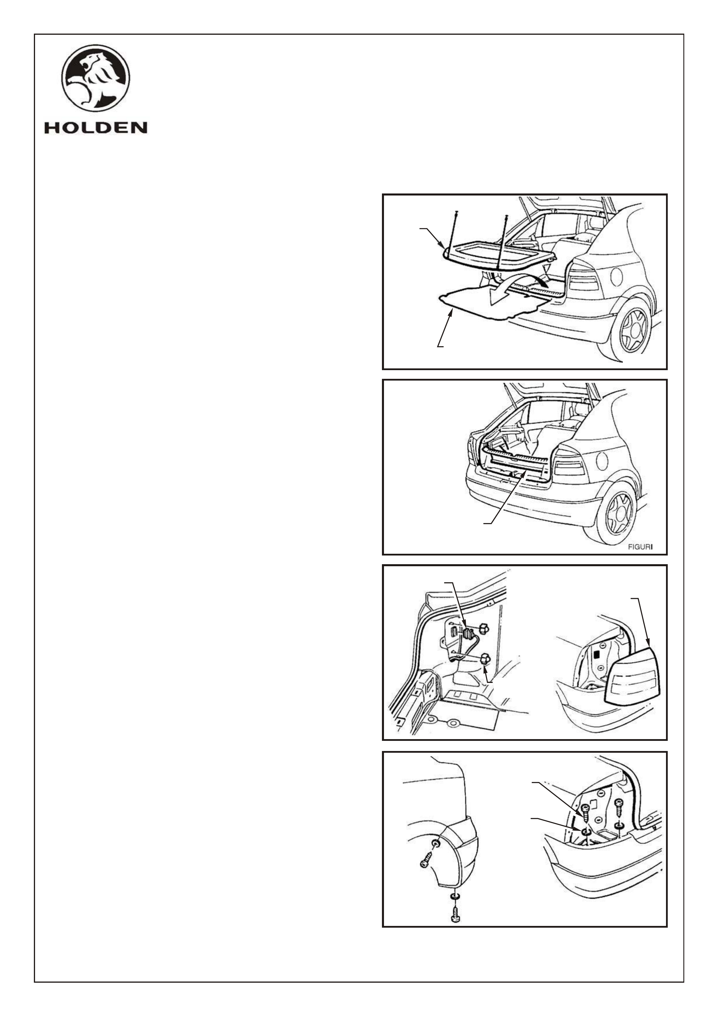
8. Remove six Torx head screws and washers from
rear bumper facia as shown in Figure 5.
9. Disconnect licence plate lamp connector and
remove rear bumper facia.
10. Disconnect two muffler hanger rubbers from rear
muffler and hanger mounts. Allow rear muffler to
hang, to provide access to LHS tow bar mounting
location.
11. Mark area on LHS of rear compartment floor where
boot plate will be fitted and scrape deadener from
this area, as shown in figure 8.
NOTE: Use a heat gun to soften deadener and aid
removal
FIGURE 5
SCREW
(6 PLACES)
WASHER
(6 PLACES)
FIGURE 6
BUMPER
FACIA
LICENCE PLATE
LAMP
CONNECTOR
FIGURE 7
REAR MUFFLER
MUFFLER
HANGER
RUBBER
(2 PLACES)
FIGURE 8
REMOVE
FLOOR
DEADENER
(LHS ONLY)
FD869
21DE00
G37-04a
Page 4 of 6
HOLDEN SERVICE PARTS OPERATIONS
Reproduction in whole or part
prohibited without written approval
Division of HOLDEN Ltd ACN 006 893 232
COPYRIGHT
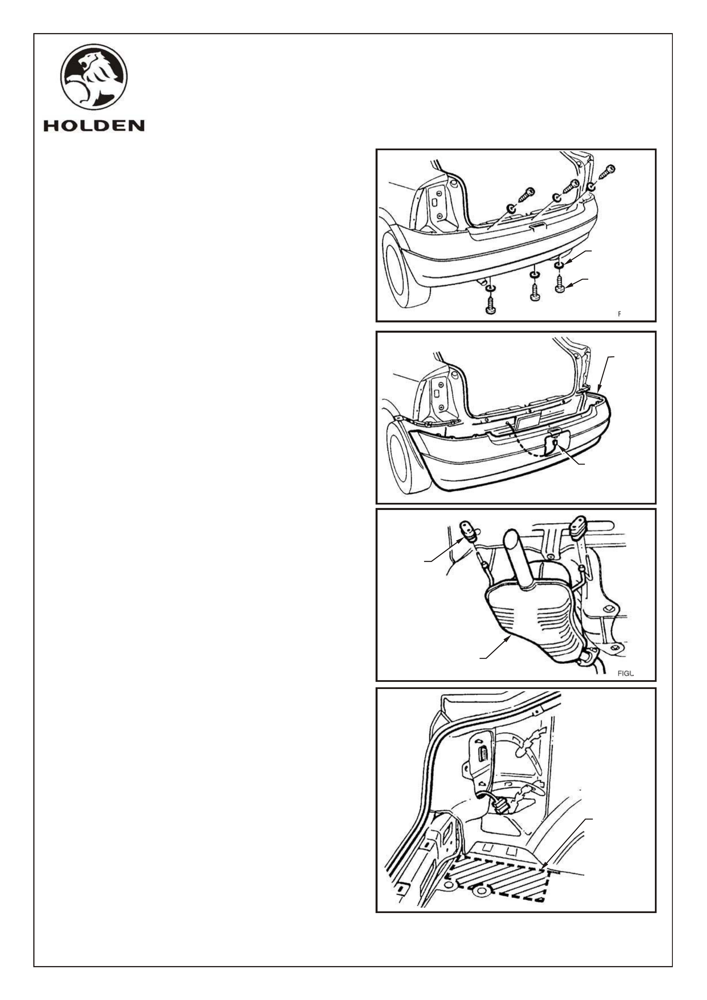
12. Drill two 20mm dia. holes(through floor panel only),
at dimple locations on LHS and RHS of rear
compartment floor.
NOTE: Do not drill centre most of three dimples .
13. Apply metal primer, around holes and to any bare
metal surfaces and allow to dry.
14. Apply silicone or butyl sealer around holes prior to
installing boot plates, for water sealing and
corrosion protection.
15. Instal spacers, boot plates and coach bolts to LHS
and RHS of rear compartment. Use two short
spacers and two 90mm coach bolts for LHS. Use
two longer spacers and two 100mm coach bolts for
RHS.
NOTE: Both boot plates must be installed with longer cut
off corner inboard, to provide correct floor coverage and
prevent boot plate fouling spare wheel well on RHS .
16. Drill off two rivets from each of two crush boxes on
rear panel. Remove and retain crush boxes to
return to customer.
17. Offer tow bar to rear of vehicle.
NOTE: Crush boxes may be refitted using rivets supplied
in package, if customer removes tow bar in the future.
18. Attach tow bar at LHS using two M10 flange nuts .
Hand tighten.
19. Attach tow bar at RHS using two M10 flange nuts.
Tighten nuts to 45Nm.
20. Tighten two M10 flange nuts at LHS to 45Nm, refer
Figure 11.
FIGURE 9
DRILL 20.0 DIA HOLE
HROUGH FLOOR
PANEL ONLY
(2 PLACES
EACH SIDE)
AT DIMPLE
LOCATIONS,
T
BOOT PLATE,
COACH BOLT,
SPACER
ASSEMBLY
FIGURE 10
TOW BAR
ASSEMBLY
FIGURE 11
FLANGE NUT, M10
(2 PLACES)
45Nm
FIGURE 12
FLANGE NUT, M10
(2 PLACES)
45Nm
REMOVE AND
RETAIN
CRUSH BOXES
DO NOT DRILL
CENTRE MOST DIMPLE
FD869
21DE00
G37-05a
Page 5 of 6
HOLDEN SERVICE PARTS OPERATIONS
Reproduction in whole or part
prohibited without written approval
Division of HOLDEN Ltd ACN 006 893 232
COPYRIGHT
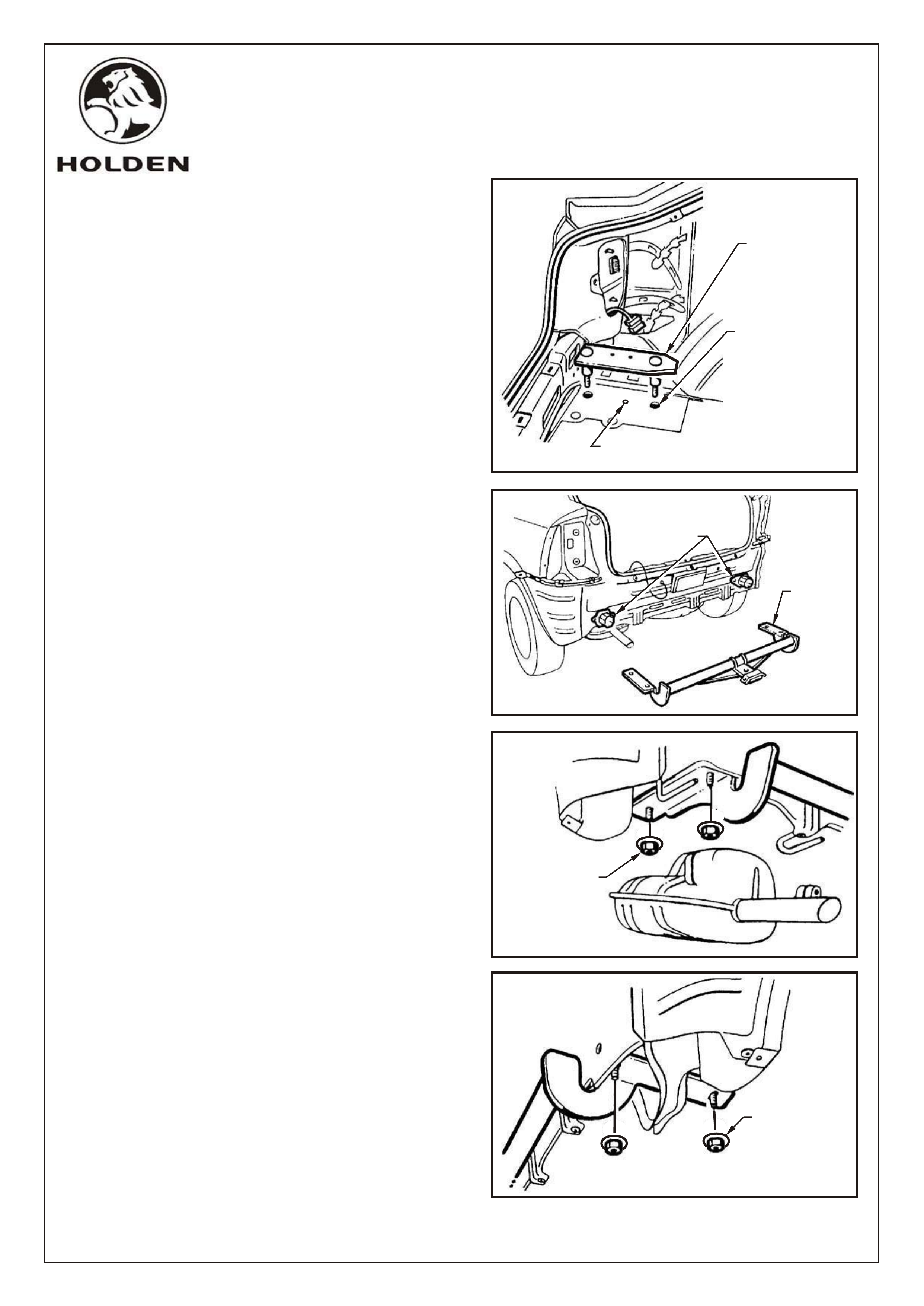
21. Attach tow bar tongue using two M16 x 45.0 bolts
and spring washers. Tighten M16 x 45.0 bolts 80-
90Nm.
22. Refit rear muffler with two muffler hanger rubbers.
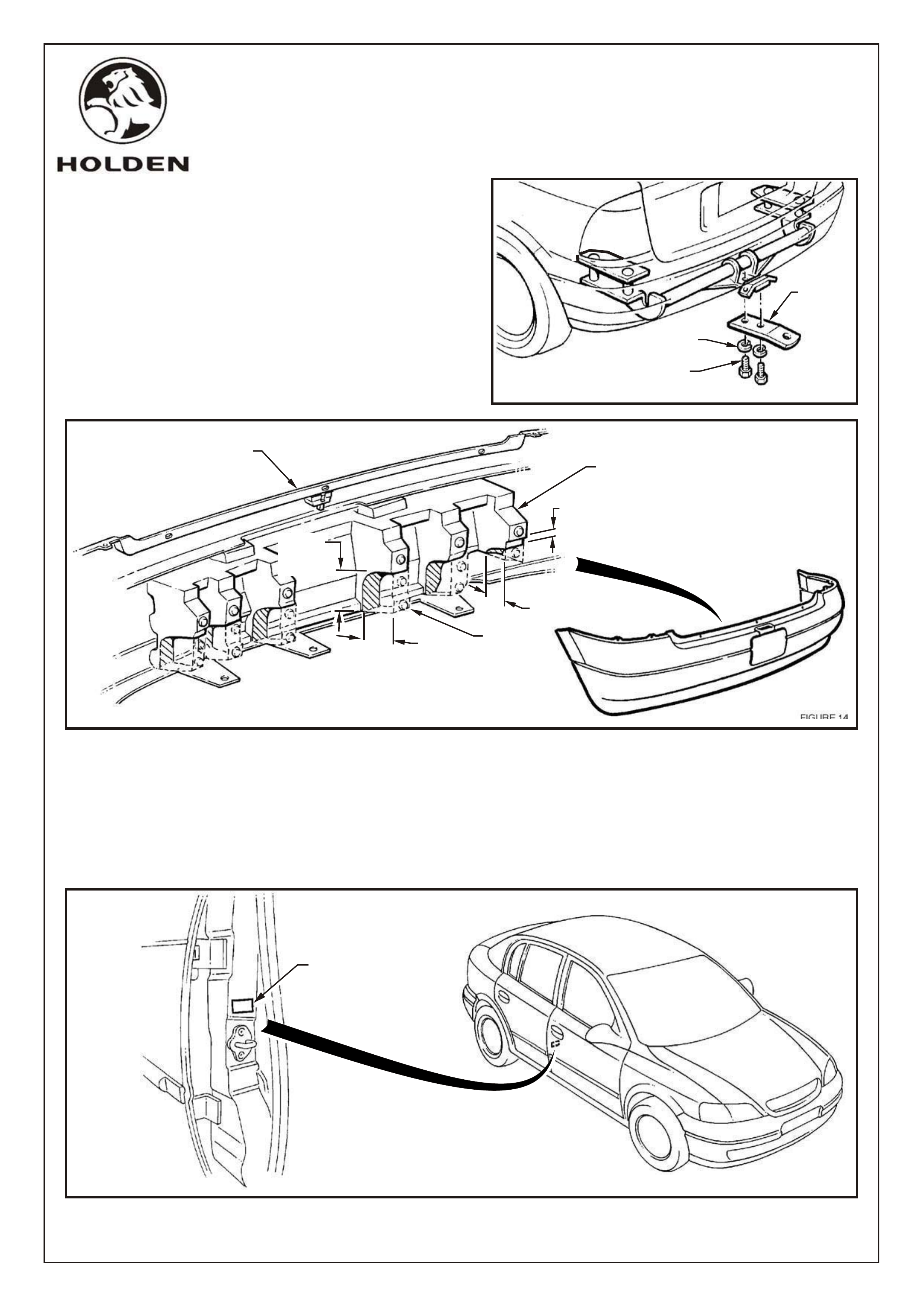
23. Before refitting rear bumper facia, the foam energy
absorber on the inner surface of the facia, must be
modified where it would otherwise interfere with the
tow bar. Cut out sections of energy absorber as
indicated in Figure 14.
TOW BAR
TONGUE
SPRING WASHER
16mm, (2 PLACES)
BOLT, M16
(2 PLACES)
80-90Nm FIGURE 13
FIGURE 15
WIPE SURFACE CLEAN
PRIOR TO APPLICATION
OF ADR LABEL
24. Refit rear bumper facia ensuring an interference free fit between the energy absorber and tow bar. Reconnect
licence plate lamp connector.
25. Refit LHS and RHS rear tail lamps.
26. Refit back panel lower cover and rear compartment floor carpet.
FIGURE 14
70mm
(TYPICAL,
5 PLACES))
20mm
70mm
70mm
(TYPICAL,
5 PLACES)
REAR BUMPER
ENERGY ABSORBER
CUT OUT
SECTIONS
AS INDICATED
REAR BUMPER FACIA
FD869
21DE00

HOLDEN SERVICE PARTS OPERATIONS
COPYRIGHT
Reproduction in whole or part
prohibited without written approval
COPYRIGHT
Division of HOLDEN Ltd ACN 006 893 232
TS ASTRA HATCH BACK, 1000kg TOW BAR PACKAGE
Part No. 92079514
PARTS LIST
ITEM DESCRIPTION QUANTITY
92078594 TOWBAR ASSEMBLY, CONSISTS OF:
TOWBAR MAIN ASSEMBLY 1
BOOT PLATE ASSEMBLY (LHS) 1
BOOT PLATE ASSEMBLY (RHS) 1
FLANGE NUT, M10 4
92078748 TOW BAR TONGUE 1
92077203 D - SHACKLE 1
92081424 BOLT - M16 x 45, GRADE 8.8 2
92079512 SPRING WASHER - 16mm 2
ADR LABEL 1
FD796 WARRANTY CARD 1
FD869 FITTING INSTRUCTION BOOKLET 1
NOT INCLUDED IN TOW BAR PACKAGE, AVAILABLE SEPARATELY:
92078418 TRAILER WIRING HARNESS
G37-06a
Page 6 of 6
FD869
21DE00