FITTING INSTRUCTIONS FOR
VS TRANSMISSION OIL COOLER PACKAGE (V8)
Part Number M41535
FD824
15JL98
COPYRIGHT
Page 1 of 4
3207a-01
HOLDEN SERVICE PARTS OPERATIONS
Reproduction in whole or part
prohibited without written approval
Division of HOLDEN Ltd ACN 006 893 232

1
25,0 - 12,0Nm
1,0 - 3,0Nm
A
VIEW
DRILL 3.9 DIA. HOLE
(2 PLACES)
SCREW
SP2058
(2 PLACES)
NUT
11065574
(4 PLACES)
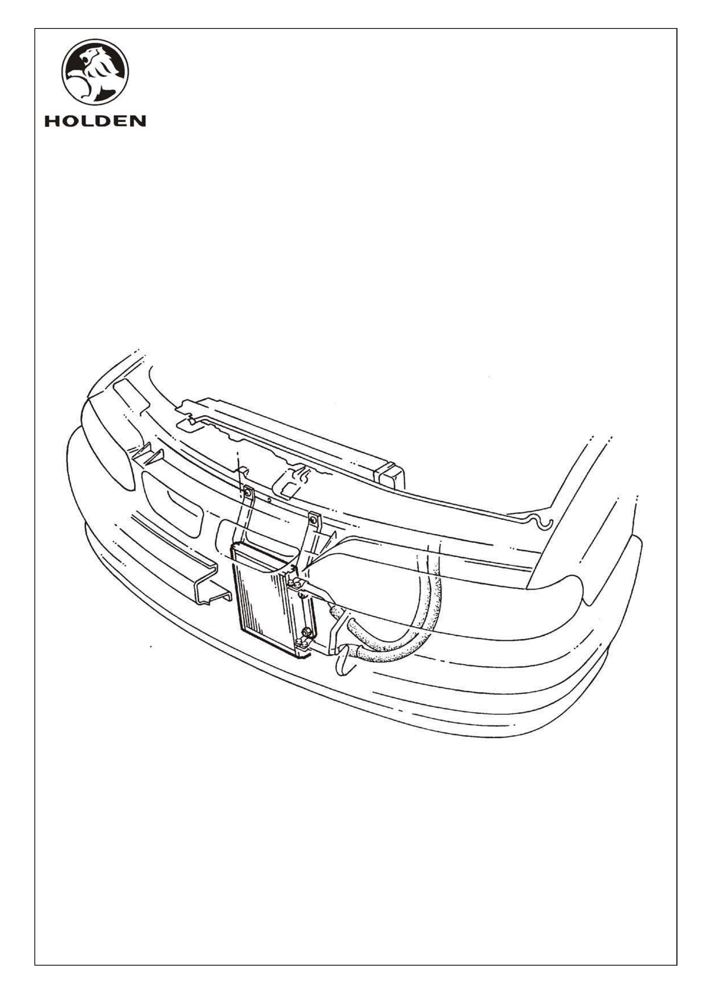
OIL COOLER
92041215
RELOCATE
BRACKET
EXISTING MOUNTING
BRACKET HOLES
NOTE: CLEAN ALL
CONTAMINANTS, OIL
AND DIRT AROUND
UNUSED HOLES.
APPLY METAL PRIMER,
DULUX EPOXY PRIMER
SURFACER (DEPS)
410-39790 (BLACK), OR
EQUIVALENT NEATLY
AROUND HOLES.
80.5
112.0
2
1
A-A
SECTION
FRONT
BUMPER
SUPPORT
GRILLE
FRONT MEMBER ASM.
- LOWER
FRONT
AIR DAM
A
C
L
A
A
C
L
OF
CAR
TIGHTEN THIS CLAMP FIRST
4,0 MAX
(BETWEEN TABS
AFTER
TIGHTENING)
TIGHTEN THIS CLAMP SECOND
VIEW B
1,0 - 2,0
B
CLAMP
11093191
(4 PLACES)
FD824
15JL98
COPYRIGHT
Page 2 of 4
3207a-02
HOLDEN SERVICE PARTS OPERATIONS
Reproduction in whole or part
prohibited without written approval
Division of HOLDEN Ltd ACN 006 893 232

V8 TRANSMISSION OIL COOLER PACKAGE
FITTING INSTRUCTIONS
1. Disconnect battery negative terminal.
2. Remove grille and front air dam, refer VS Service Manual Volume 1.
3. Mark screw hole locations for new position of inboard transmission oil cooler bracket,
one hole in front panel upper and one hole in front member lower, refer view A, and drill
3.9mm dia. holes.
4. Disconnect both oil cooler hoses from existing external tranmission oil cooler. Plug
or cover hose ends, to prevent loss of transmission oil.
NOTE: Do not allow contaminants to enter cooler hoses while detached from oil cooler.
5. Remove existing oil cooler from two mounting brackets.
6. Remove inboard mounting bracket. Fix bracket at new location using self tapping
screws (SP2058) and torque screws 1,0 - 3,0Nm.
NOTE: Outboard oil cooler bracket does not require removal.
7. Clean all contaminants, oil and dirt from around holes left from previous oil cooler
inboard mounting bracket screws. Apply metal primer, Dulux Epoxy Primer Surfacer
(DEPS) 410-39790 (Black) or equivalent neatly around holes.
8. Fit new larger oil cooler (92041215) to mounting brackets with nuts (11065574).
Torque nuts 5,0 - 12,0Nm.
9. Reconnect oil cooler hoses to new oil cooler using two new clamps (11093191) on each
hose end. Position the two clamps together 1,0 - 2,0mm from end of hose and tighten
in correct sequence, refer view B. Clamp furthest from hose end is to be tightened first.
After tightening, clamps must have less than 4,0mm between tabs, refer view B.
10. Check transmission oil level (cold) before starting engine.
11. Reconnect battery negative terminal.
12. Run engine, select all gears through transmission. Check oil cooler hose connections
to oil cooler for leaks. Check transmission oil level when at operating temperature,
top up if neccessary.
NOTE: Transmission should require top up of oil due to new larger capacity oil cooler.
13. Reinstall grille and front air dam, refer VS Service Manual Volume 1.
FD824
15JL98
COPYRIGHT
Page 3 of 4
3207a-03
HOLDEN SERVICE PARTS OPERATIONS
Reproduction in whole or part
prohibited without written approval
Division of HOLDEN Ltd ACN 006 893 232

V8 TRANSMISSION OIL COOLER PACKAGE
PARTS LIST
PART NUMBER DESCRIPTION QUANTITY
92041215 TRANSMISSION OIL COOLER 1
SP2058 SELF TAPPING SCREW 2
11065574 NUT 4
11093191 CLAMP 4
FD824
15JL98 Figure x
COPYRIGHT
Page 4 of 4
3207a-04
HOLDEN SERVICE PARTS OPERATIONS
Reproduction in whole or part
prohibited without written approval
Division of HOLDEN Ltd ACN 006 893 232