
FITTING INSTRUCTIONS FOR
VT WAGON (V6 & 5.0 V8)
2100KG TOW BAR PACKAGE.
Part Number 92140146
NOT INCLUDED IN TOW BAR PACKAGE, BUT MANDATORY TO FIT:
92056715 TOW BAR SURROUND TRIM (WAGON)
92059847 PACKAGE - HEAT SHIELDS, UNDER CARPET
92053241 PACKAGE - HEAT SHIELD, CENTRE BEARING
92140101 PACKAGE - LOAD DISTRIBUTION HITCH (ADJUSTABLE)
92057694 PACKAGE - POWER STEERING FLUID COOLER
92140139 PACKAGE - SUPERLIFT SHOCK ABSORBERS (WAGON)
FD954
07MR00
COPYRIGHT
Page 1 of 8
fd954_1
HOLDEN SERVICE PARTS OPERATIONS
Reproduction in whole or part
prohibited without written approval
Division of HOLDEN Ltd ACN 006 893 232

2100KG TOW BAR FITTING INSTRUCTIONS (WAGON)
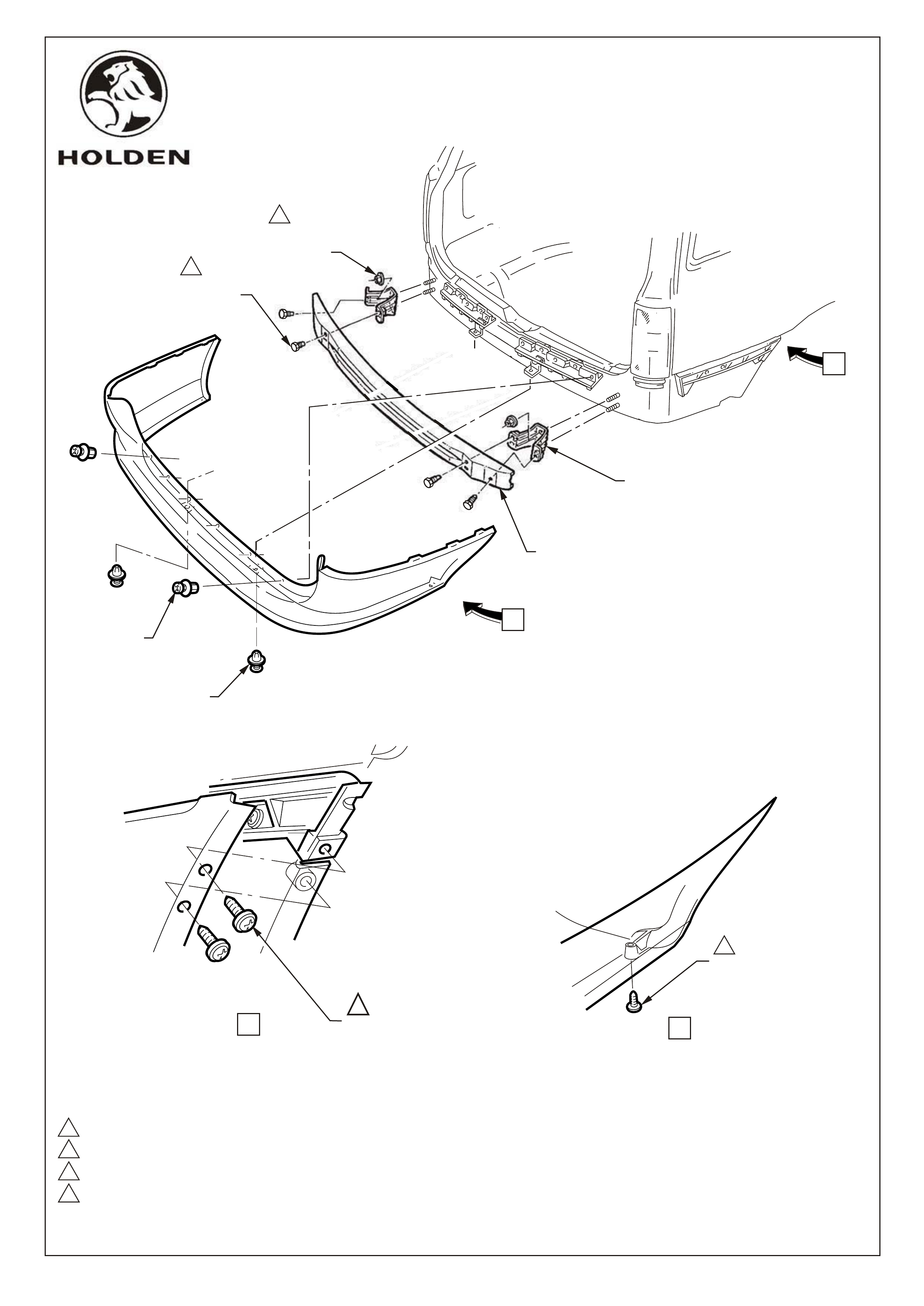
REAR BUMPER BAR SUPPORT BEAM & BRACKETS REMOVAL
Remove spare wheel cover and spare wheel from rear compartment.
Remove 6 scrivets at upper edge of facia, refer figure 1.
Remove 2 scrivets, lower facia edge, refer figure 1.
Remove 6 screws, facia to rear edge of wheelhouse, refer figure 1, views A and B.
With facia supported, pull facia sides outward disconnecting facia from side supports and slide rearwards
removing facia, refer figure 1.
Remove bolts securing bumper support beam to brackets. Refer figure 1.
Remove 4 nuts securing bumper support beam brackets to vehicle (4 places) and remove brackets,
refer figure 1.
1.
2
3.
4.
5.
6.
7.
FD954
07MR00
COPYRIGHT
Page 2 of 8
fd954_2
HOLDEN SERVICE PARTS OPERATIONS
Reproduction in whole or part
prohibited without written approval
Division of HOLDEN Ltd ACN 006 893 232
1,0 - 3,0 Nm
6,0 - 9,0 Nm
35,0 - 52,0 Nm
50,0 - 80,0 Nm
4
3
2
1
VIEW A
11
SCREW
(2 PLACES
R & L SIDE)
VIEW B
SCREW
1
FD954
07MR00 Figure 1
Page 3 of 8
fd954_3
COPYRIGHT
HOLDEN SERVICE PARTS OPERATIONS
Reproduction in whole or part
prohibited without written approval
Division of HOLDEN Ltd ACN 006 893 232
NUT
(2 PLACES
R & L SIDE)
SCRIVET
(6 PLACES)
REAR BEAM
MOUNTING BRACKET
REAR BUMPER
SUPPORT BEAM ASM.
SCRIVET
(2 PLACES)
BOLT
(2 PLACES
R & L SIDE)
3
4
A
B

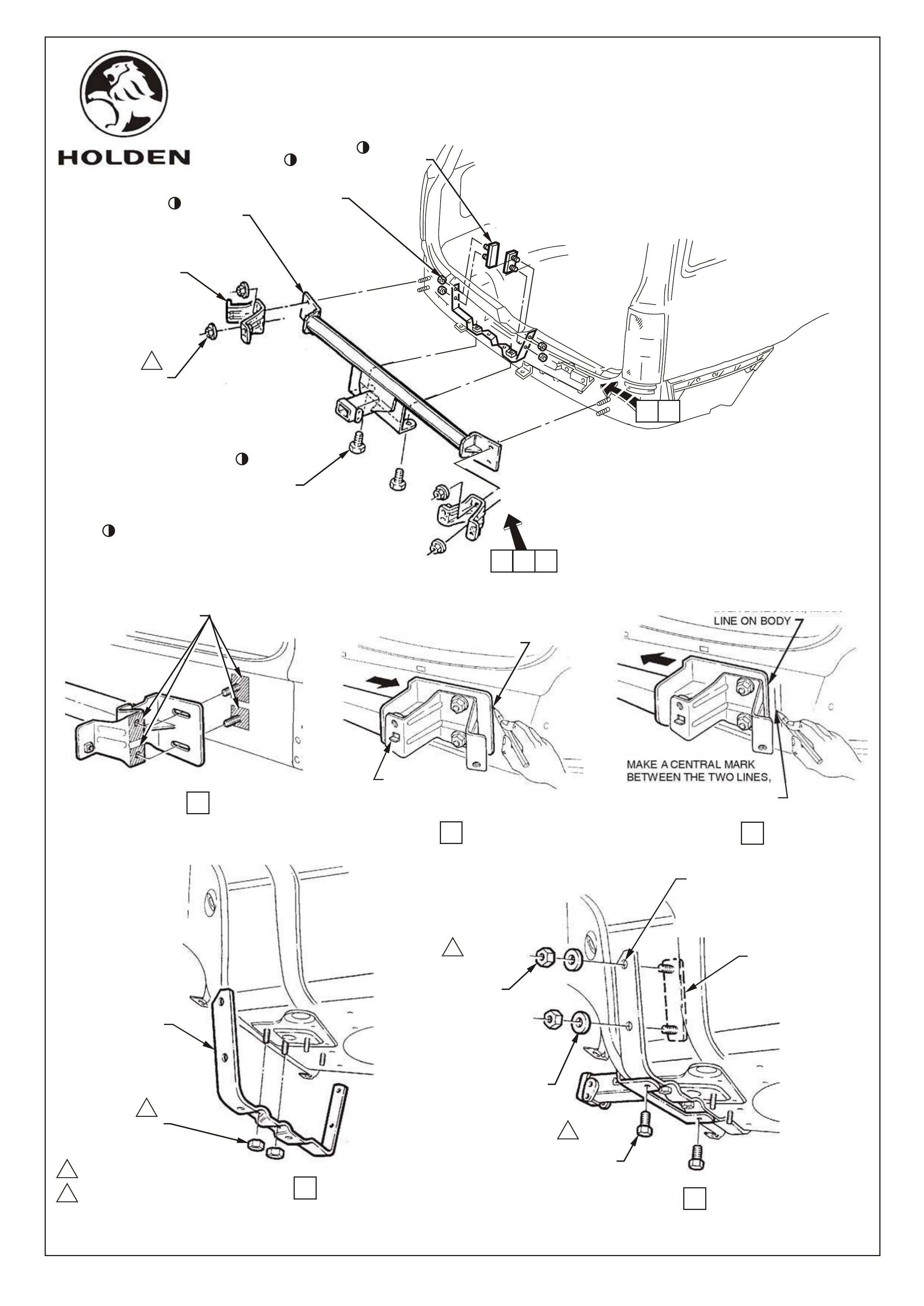
TOW BAR INSTALLATION
Smear a thin film of grease to bare metal exposed by removal of brackets, to vehicle body and rear face of
bracket to prevent corrosion, refer figure 2, view A.
Install spare wheel well brace assembly to underside of spare wheel well using two existing rearmost
weldstuds, refer figure 2, view D.
Loosely fit two M10 nuts to weld studs.
Install tow bar to 4 beam support studs, refit beam support brackets over tow bar mounting plates, fit nuts
and hand tighten (4 places).
NOTE : Brackets must be installed with tab on flange inboard of vehicle refer figure 2, view B.
Loosely fit two M10 bolts to attach tow bar main assembly to spare wheel well brace assembly.
IMPORTANT: Due to elongated holes in tow bar mounting plates, tow bar will have 10-15mm sideways
travel on rear of car. Tow bar must be accurately centralised on vehicle to ensure bumper
facia cutout aligns with tow bar tongue upon reassembly.
To centralise bar, first slide bar to extremity of travel to RH side of vehicle and mark position of edge of RH
mounting plate on body, refer figure 2, view B.
Slide bar across to extremity of travel to LH side of vehicle and mark RH mounting plate edge position
on body, refer figure 2, view C.
Make a central mark between these two lines (this will centre towbar) & reposition towbar to centre
line.
Tighten nuts securing beam support brackets and tow bar mounts to body, 50 - 80Nm (4 places),
refer figure 2.
Tighten nuts securing spare wheel well brace assembly to underbody weld studs, 30 - 40Nm,
(2 places)
Tighten bolts securing main tow bar assembly to spare wheel well brace assembly, 30 - 40Nm,
(2 places)
Use spare wheel well brace assembly as a template to drill two 10,0 dia. holes each side of spare
wheel well, refer figure 2, view E.
WARNING : Be sure spare wheel has been removed from spare wheel well before drilling holes.
Apply silicone or butyl sealer to holes for water sealing & corrosion protection purposes, 4 places.
Install two adhesive backed stud plates from inside spare wheel well, through holes in wheel well and spare
wheel well brace assembly.
From underside of vehicle attach flat washers and M10 nuts to stud plate studs,(4 places) refer figure 2,
view E.
Tighten spare wheel well brace assembly to stud plate nuts 30 - 40Nm (4 places).
Refit bumper beam, and tighten 35 - 52Nm.
8.
9.
10.
11.
12.
13.
14.
15.
16.
17.
18.
19.
20.
21.
22.
23.
24.
FD954
07MR00
COPYRIGHT
Page 4 of 8
fd954_4
HOLDEN SERVICE PARTS OPERATIONS
Reproduction in whole or part
prohibited without written approval
Division of HOLDEN Ltd ACN 006 893 232
REAR BUMPER
BEAM SUPPORT
BRACKET
NUT
(2 PLACES
R &L SIDE)
2
NUT
(2 PLACES
R &L SIDE)
1
2
PART OF TOW BAR PACKAGE
BOLTS
(2 PLACES)
TOW BAR
ASSEMBLY
STUD PLATE
(2 PLACES)
C
A B
30,0 - 40,0 Nm
50,0 - 80,0 Nm
E
D
SLIDE TOW BAR TO
EXTREMITY OF TRAVEL
IN RH DIRECTION, MARK
LINE ON BODY
RH SHOWN
BRACKET MUST
BE INSTALLED
WITH TAB INBOARD
VIEW B
SLIDE TOW BAR TO
EXTREMITY OF TRAVEL
IN LH DIRECTION, MARK
LINE ON BODY
MAKE A CENTRAL MARK
BETWEEN THE TWO LINES,
ALIGN TOW BAR EDGE TO
THIS MARK TO CENTRALISE
TOW BAR
VIEW C
VIEW D
COAT BARE METAL
SURFACES WITH A
THIN FILM OF GREASE
RH SHOWN
VIEW A
NUT
(2 PLACES)
1
SPARE WHEEL
WELL BRACE
ASSEMBLY.
VIEW E
1
STUD PLATE
(2 PLACES)
FLAT
WASHER
(2 PLACES
R & L SIDE)
NUT
(2 PLACES
R & L SIDE)
1
BOLT
(2 PLACES)
USE SPARE WHEEL WELL BRACE
ASSEMBLY AS A TEMPLATE TO
DRILL 12.5 DIA. HOLES
(2 PLACES EACH SIDE)
FD954
07MR00 Figure 2
COPYRIGHT
Page 5 of 8
fd954_5
HOLDEN SERVICE PARTS OPERATIONS
Reproduction in whole or part
prohibited without written approval
Division of HOLDEN Ltd ACN 006 893 232
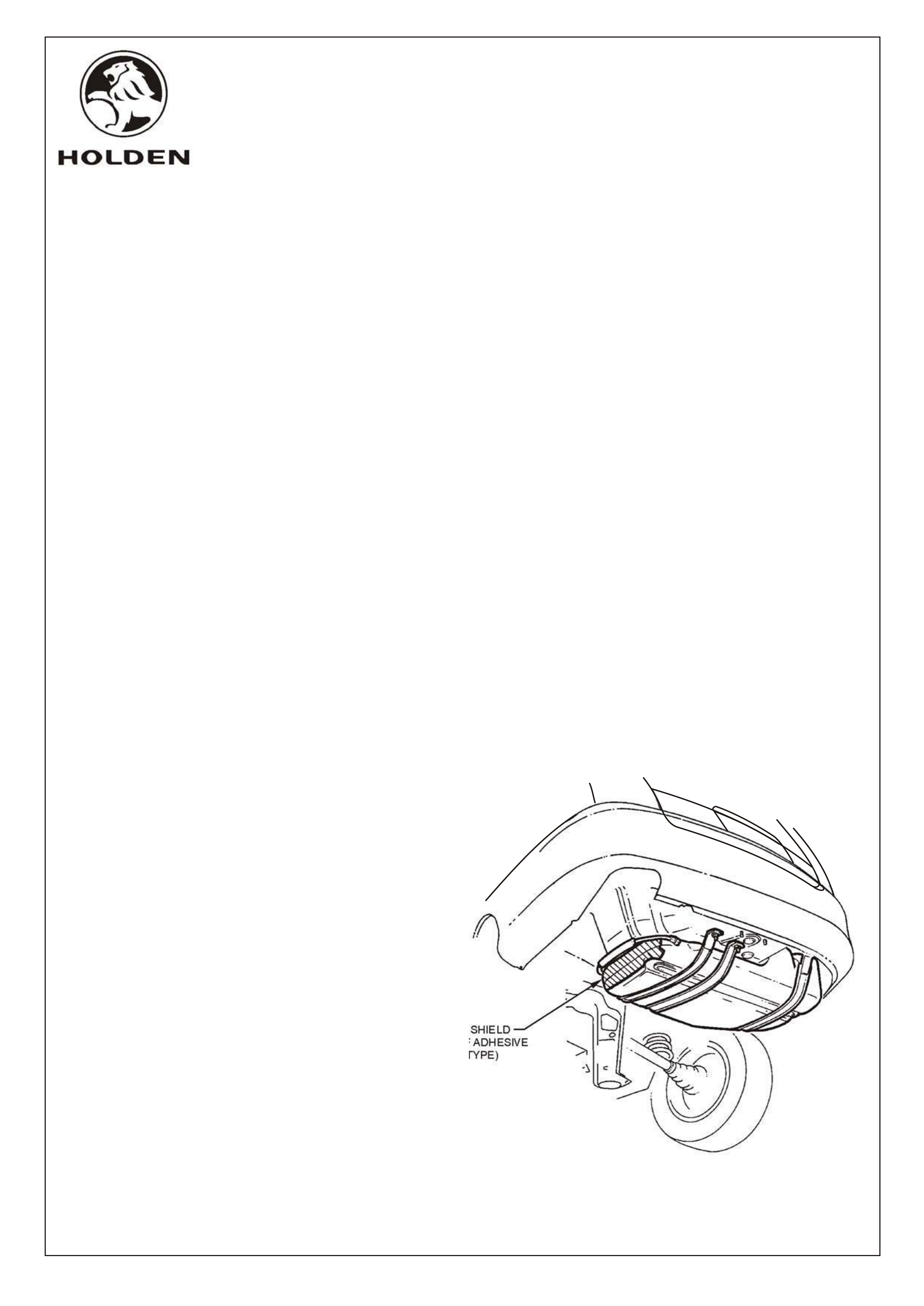
NOTE: A fuel tank heat shield may require fitment
to some early model vehicles, if not already in
place. Check side of fuel tank adjacent to rear
muffler, refer diagram. If not already in place, heat
shield (Part No. 92037805) must be purchased
separately and fitted to fuel tank as per instructions
contained with heat shield.
FUEL TANK HEAT SHIELD LOCATION
HEAT SHIELD
(SELF ADHESIVE
FOIL TYPE)
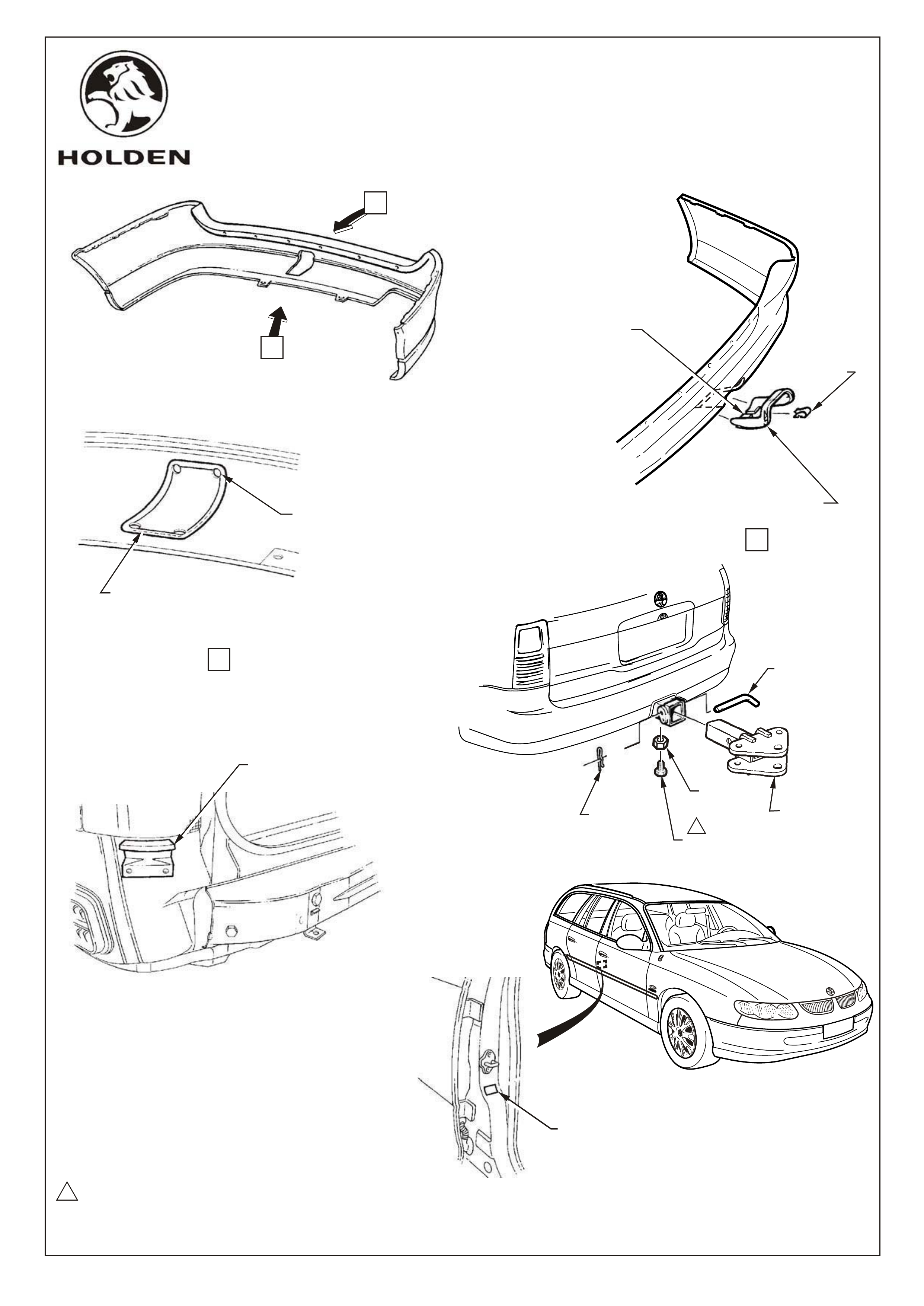
Before facia refit, tow bar tongue hole must be cut in bumper facia.
Drill 5.0mm dia. hole at each corner of marked area on inside surface of bumper facia,
refer figure 3, view A.
IMPORTANT : Do not drill or cut outside of outer guide line on facia as escutcheon will not cover.
Cut between drilled holes with small saw using care not to deviate from between moulded guide lines.
refer figure 3, view A.
Carefully neaten sawn edges with file or sand paper using extreme care not to mark painted finish
on bumper facia.
Trial fit tow bar tongue surround to facia to ensure correct fit before reinstalling facia,
refer figure 3, view B. (Do not fit surround before reinstalling facia)
Reinstall facia in reverse to removal procedure.
NOTE : Be sure to position facia correctly over locating tabs on each corner of body,
below tail lights, refer figure 3.
Feed tow bar tongue surround over tongue mount and snap fit to bumper facia cutout.
Install tow bar tongue to tow bar asm. Using M16 bolt, M16 nut and safety clip, refer figure 3.
Tighten nut 80 - 90Nm.
Install trailer wiring harness as per fitting instructions included in trailer wiring harness package.
Clean surface of drivers side B pillar and apply ADR label, refer figure 3.
25.
26.
27.
28.
29.
30
31.
32.
33.
34.
FD954
07MR00
COPYRIGHT
Page 6 of 8
fd954_6
HOLDEN SERVICE PARTS OPERATIONS
Reproduction in whole or part
prohibited without written approval
Division of HOLDEN Ltd ACN 006 893 232
NOTE: Once tow bar installation is complete,
place Fitting Instruction booklet in glove box of
vehicle.
CUT BETWEEN DRILLED HOLES
WITH SMALL SAW. DO NOT DEVIATE
FROM BETWEEN TWO MOULDED
GUIDE LINES ON BUMPER FACIA
DRILL 5.0 DIA HOLE (4 PLACES)
NOTE : KEEP HOLE EDGE WITHIN
OUTER GUIDE LINE
TRIAL FIT TOW
BAR SURROUND BEFORE
REINSTALLING BUMPER FACIA
80 - 90Nm
WHEN REINSTALLING BUMPER,
BE SURE TO POSITION FACIA
CORRECTLY OVER LOCATING TABS
AT EACH CORNER OF BODY.
1
A
B
VIEW A
VIEW B
SLIT LOWER EDGE OF
TOW BAR SURROUND
TO AID FITMENT
FIT CLIP OVER
SLIT, ONCE
INSTALLED
FD954
05MY00 Figure 3
COPYRIGHT
Page 7 of 8
fd954_7
HOLDEN SERVICE PARTS OPERATIONS
Reproduction in whole or part
prohibited without written approval
Division of HOLDEN Ltd ACN 006 893 232
WIPE SURFACE CLEAN
PRIOR TO APPLICATION
OF ADR LABEL
SAFETY CLIP TOW BAR
TONGUE
NUT M10
ANTI -RATTLE BOLT M10 x 25
(ONLY USE WHEN UNLOADED)
1
RETAINER
PIN

2100 KG TOW BAR PACKAGE
FOR VT COMMODORE WAGON (V6 & 5.0 V8)
Part number 92140146
PART NO. DESCRIPTION QUANTITY
92047638 TOW BAR MAIN ASSEMBLY 1
92054275 BRACE ASSEMBLY - SPARE WHEEL WELL 1
NUT M10 2
BOLT M10 x 25 2
STUD PLATE ASM. 2
NUT M12 4
BOLT M12 x 25 2
FLAT WASHER M12 6
FLAT WASHER M10 2
ADR LABEL 1
FD954 TOW BAR FITTING INSTRUCTION BOOKLET 1
FD796 WARRANTY CARD 1
92077203 'D' RING SAFETY SHACKLE 2
BOLT - ANTI RATTLE - M10 x 25mm 1
NUT - ANTI RATTLE - M10 1
NOT INCLUDED IN TOW BAR PACKAGE, BUT MANDATORY TO FIT:
92056715 TOW BAR SURROUND TRIM (WAGON)
92059847 PACKAGE - HEAT SHIELDS, UNDER CARPET
92053241 PACKAGE - HEAT SHIELD, CENTRE BEARING
92140101 PACKAGE - LOAD DISTRIBUTION HITCH (ADJUSTABLE)
92057694 PACKAGE - POWER STEERING FLUID COOLER
92140139 PACKAGE - SUPERLIFT SHOCK ABSORBERS
NOTE: FIT ALL 'MANDATORY TO FIT' ITEMS IN ACCORDANCE WITH FITTING INSTRUCTIONS
CONTAINED IN EACH PACKAGE.
NOT INCLUDED IN TOW BAR PACKAGE, BUT AVAILABLE SEPARATELY:
92140088 TRAILER WIRING HARNESS - FLAT 7 PIN
92140147 TRAILER WIRING HARNESS - ROUND 7 PIN (LARGE PIN)
92140148 TRAILER WIRING HARNESS - ROUND 7 PIN (SMALL PIN WITH BACKING PLATE)
92047624 PACKAGE - TOW BAR TONGUE
92140068 TOW BALL ASSEMBLY (CHROME)
92140106 TOW BALL COVER
SMALL PARTS KIT
92037805 HEAT SHIELD - FUEL TANK, (REQUIRED ONLY IF NOT ALREADY FITTED TO VEHICLE)
FD954
05MY00
COPYRIGHT
Page 8 of 8
fd954_8
HOLDEN SERVICE PARTS OPERATIONS
Reproduction in whole or part
prohibited without written approval
Division of HOLDEN Ltd ACN 006 893 232
PARTS LIST