
IMPORTANT SAFETY NOTICE
Proper service and repair is important to the safe, reliable operation of all motor vehicles.
The service procedures recommended by HOLDEN Ltd A.C.N. 006 893 232 and
described in this publication are effective methods for performing service operations.
Some of these service operations require the use of tools specially designed for the
purpose. The special tools should be used when and as recommended.
It is important to note that some warnings against the use of specific service methods that
can damage the vehicle or render it unsafe are stated in this publication. It is important to
understand these warnings are not exhaustive HOLDEN Ltd could not possibly know,
evaluate and advise the service trade of all conceivable ways in which service might be
done or of all the possible hazardous consequences of each way. Consequently HOLDEN
Ltd has not undertaken any such broad evaluation. Accordingly, anyone who uses a
service procedure or tool which is not recommended HOLDEN Ltd, must first be
thoroughly satisfied that neither personal safety nor vehicle safety will be jeopardised by
the service method selected.

HOLDEN
VY & VY2 SERIES COMMODORE &
WK SERIES STATESMAN
V6 AFTERSALES LPG KIT
INSTALLATION INSTRUCTIONS
FOREWORD
The information in these installation instructions, when
used in conjunction with the VY, VY2 & WK Series Service
Information will provide installation procedures for the
HOLDEN Ltd approved aftersales LPG kit for VY, VY2 &
WK Series vehicles with V6 engine and automatic
transmission.
THE INSTALLATION INSTRUCTIONS AND SERVICE
PROCEDURES DETAILED IN THIS BOOKLET ARE
BASED ON USING THE APPROVED HOLDEN QUALITY
REPLACEMENT PARTS AVAILABLE FROM
AUTHORISED HOLDEN PARTS OUTLETS.
The Table of Contents on this page enables the user to
locate the numeric identifier for each Section. In addition,
numeric identifiers are used to signify the individual
operations within the Sections.
A list of installation tools, where required, is also included
in Sections 5.
Installation Tools, unless otherwise specified, are available
from:
IMPCO TECHNOLOGIES.
1 - 3 Taunton Drive
Cheltenham, Vic 3192
All correspondence to:
PO Box 233,
Cheltenham, Vic 3192
Telephone: (03) 9584 5644
Fax. (03) 9583 0696
HOLDEN Ltd does not endorse, prefer, or assume
responsibility for the products of this firm nor for any such
items which may be available from other makers.
All information, illustrations and specifications contained in
this Booklet are based on the latest product information
available at the time of publication approval. The right is
reserved to make changes at any time without notice.
PRINTED IN AUSTRALIA
TABLE OF CONTENTS
1 LPG INSTALLATION
INSTRUCTIONS
2 LPG LEAK TESTING
3 TECH 2 LPG SET-UP & ENABLE
PROCEDURES
4 LPG AFTER INSTALLATION
CHECK
5 LPG INSTALLATION TOOLS
6 PARTS LIST
HOLDEN Ltd A.C.N. 006 893 232
SERVICE DEPARTMENT
COPYRIGHT - HOLDEN Ltd
Reproduction in whole or in part prohibited without written approval

NOTES
_________________________________________________________________________________________________
_________________________________________________________________________________________________
_________________________________________________________________________________________________
_________________________________________________________________________________________________
_________________________________________________________________________________________________
_________________________________________________________________________________________________
_________________________________________________________________________________________________
_________________________________________________________________________________________________
_________________________________________________________________________________________________
_________________________________________________________________________________________________
_________________________________________________________________________________________________
_________________________________________________________________________________________________
_________________________________________________________________________________________________
_________________________________________________________________________________________________
_________________________________________________________________________________________________
_________________________________________________________________________________________________
_________________________________________________________________________________________________
_________________________________________________________________________________________________
_________________________________________________________________________________________________
_________________________________________________________________________________________________
_________________________________________________________________________________________________
_________________________________________________________________________________________________
_________________________________________________________________________________________________
_________________________________________________________________________________________________
_________________________________________________________________________________________________
_________________________________________________________________________________________________
_________________________________________________________________________________________________
_________________________________________________________________________________________________
_________________________________________________________________________________________________
_________________________________________________________________________________________________
_________________________________________________________________________________________________
_________________________________________________________________________________________________
_________________________________________________________________________________________________
_________________________________________________________________________________________________
_________________________________________________________________________________________________
_________________________________________________________________________________________________
_________________________________________________________________________________________________
_________________________________________________________________________________________________
_________________________________________________________________________________________________
_________________________________________________________________________________________________
_________________________________________________________________________________________________

LPG INSTALLATION INSTRUCTIONS 1-1
SECTION 1
CAUTION:
This vehicle is equipped with a Supplemental Restraint System (SRS). A SRS will consist of either seat belt pre-
tensioners and a driver’s side airbag, seat belt pre-tensioners and a driver’s and front passenger’s airbags or
seat belt pre-tensioners, a driver’s, front passenger’s and left and right hand side airbags for the front
occupants. Before performing any service operation on or around SRS components, the steering mechanism or
w i ring, refer to the following:
For VY series vehicles, refer to Section 00 CAUTIONS AND NOTES and Section 12M OCCUPANT PROTECTION
SYSTEM in the VY & V2 Series Service Information.
For WK vehicles, refer to Section 00, CAUTIONS AND NOTES and Section 12M OCCUPANT PROTECTION
SYSTEM in the WK Series Service Information.
For VY2 series vehicles, refer to Section 00 CAUTIONS AND NOTES and Section 12M OCCUPANT PROTECTION
SYSTEM in the VY2 series Service Information.
Failure to follow the CAUTIONS and NOTES could result in SRS deployment, resulting in possible personal injury
or unnecessary SRS system repairs.
CAUTION:
Whenever any component that forms part of the ABS or ABS/ETC (if fitted), is disturbed during Service
Operations, it is vital that the complete ABS or ABS/TCS system is checked, using the procedure as detailed in
4 ABS & ABS/TCS DIAGNOSTICS, in Section 5B ABS & ABS/TCS in the VY and V2 Series Service Information.
LPG INSTALLATION INSTRUCTIONS
CONTENTS
Ref. Subject Page Ref. Subject Page
1.1 GENERAL INFORMATION............................ 1-2
1.2 SAFETY PRECAUTIONS............................... 1-3
1.3 SEQUENCE OF INSTALLATION................... 1-3
1.4 COMPONENT REMOVAL.............................. 1-4
1.5 REAR COMPARTMENT PREPARATION...... 1-5
1.6 ENGINE BAY PREPARATION....................... 1-7
1.7 LPG HARNESS INSTALLATION................... 1-7
1.8 LPG HARNESS INTERIOR ROUTING &
FUEL MODE SWITCH INSTALLATION ........ 1-8
1.9 LPG CYLINDER INSTALLATION.................. 1-14
1.10 FILLER INSTALLATION................................ 1-17
1.11 INTERMEDIATE SERVICE LINE
INSTALLATION.............................................. 1-18
1.12 FRONT SERVICE LINE INSTALLATION ...... 1-19
1.13 CONVERTER INSTALLATION...................... 1-21
1.14 COOLANT HOSE INSTALLATION ................1-22
1.15 MIXER INSTALLATION..................................1-23
1.16 AIR CLEANER INSTALLATION.....................1-25
1.17 EMERGENCY DECKLID RELEASE CABLE
EXTENSION ...................................................1-26
1.18 REAR SPRING INSTALLATION ....................1-27
1.19 COMPLIANCE PLATES & ID. LABELS –
INSTALLATION..............................................1-27
1.20 LEAK TEST ....................................................1-29
1.21 TECH 2 LPG SET-UP & ENABLE
PROCEDURES...............................................1.29
1.22 COMPONENT REINSTALLATION.................1-29
1.23 AFTER INSTALLATION CHECK....................1-29
1.24 ENABLE THE SRS & AUDIO SYSTEMS.......1-30

1-2 LPG INSTALLATION INSTRUCTIONS
1.1 GENERAL INFORMATION
The following Liquefied Petroleum Gas (LPG) installation
instructions apply to the Holden approved Aftersales LPG
Installation Kit, which can be fitted to MY 2003 VY and
MY 2004 VY2 Series sedans (excluding those fitted with
FE2 suspension) and MY 2004 WK Statesmans (excluding
Caprice) with the V6 engine and automatic transmission.
This LPG system must be fitted in accordance with these
installation instructions if the vehicle is to conform to
Australian Standard AS 1425 - 1999 and ADR 44/02.
Automotive LPG is a hydrocarbon fuel and consists primarily
of propane (60% - 90%) and butane (40% - 10%). The
propane to butane mix varies depending on the source and
manufacturing location. This gives LPG an octane rating of
approximately 110 RON.
Pure LPG is colourless, odourless and tasteless, however
commercial LPG has a pungent odour to enable LPG to be
detected by a human. This pungent odour is achieved by
adding a chemical to the LPG to enable a human to detect the
LPG at concentrations of LESS than 0.5% by volume in air.
LPG boils at approximately -40°C at atmospheric pressure,
this means that the LPG must be pressurised to
approximately 750 kPa to maintain it in a liquid state.

LPG INSTALLATION INSTRUCTIONS 1-3
1.2 SAFETY PRECAUTIONS
• DO NOT smoke or allow naked flames, or any
ignition source near th e vehicle.
• LPG must NEVER be allowed to come in contact
with any part of the body. Due to the very low
boiling point of LPG, it readily absorbs heat from
its surroundings, or any surface it comes into
contact with when released into the atmosphere.
LPG can cause severe frostbite if it is allowed to
come into contact with the human body.
• When working on the LPG system, suitable
protective clothing including gloves and safety
goggles MUST be worn to prevent personal injury.
• LPG in the vapour form is highly flammable and in
the interests of safety, the LPG system should be
leak tested and isolated by turning “OFF” the
manual service valve and draining service lines of
LPG before any service work is carried out on the
vehicle.
• During servicing, the manu al service valve must be
turned “OFF” at all times and the service lines
drained of LPG, except w hen th e gas is required to
be available for servicing or testing of the LPG
system.
• Any servicing or testing of the LPG system must
be performed by accredited personnel in a
“Specialist Gas Workshop” in accordance with
Australian Standards AS 2746 - 1985 and AS 1425 -
1999.
• Never disconnect the battery from the vehicle's
electrical system while the engine is running.
• Never disconnect or connect the SDM connector
with the ignition turned on.
• Disconnecting the battery WILL NOT immediately
deactivate the SRS. A residual energy reserve in
the SDM is incorporated to enable the pre-
tensioners and air bag/s to deploy in the event of a
battery failure. The SDM has the power to deploy
the air SRS for up to 10 seconds after the battery
has been disconnected or the ignition tu rn ed off.
• The SDM can maintain sufficien t voltage to cause a
deployment for up to 10 seconds after the ignition
switch is turned OFF or the battery is
disconnected. Many of the service operations
require disconnection of the battery to avoid an
accidental deployment of the pre-tensioners or air
bag/s.
1.3 SEQUENCE OF INSTALLATION
The following sequence is suggested for the LPG installation:
1. Component Removal: All components must be removed as
required to allow access to the various parts of the vehicle for the
LPG conversion.
2. Body Panel Modification: Holes are drilled or cut in preparation for
running the filler and service lines, vent tubes and the new wiring
harness.
3. The LPG wiring harness is installed in the vehicle.
4. Fuel Mode Switch fitted.
5. LPG Tank and Service Line Installation: The LPG tank is bolted-in
and the filler and service lines installed.
6. Engine Compartment Installation: Components such as the
converter, mixer, fuel control valve and air cleaner are fitted into
the engine compartment to complete the LPG system.
7. Emergency decklid release cable extension is installed.
8. Rear Springs or Springs and Shock absorber Installation: The rear
suspension specifications are changed to allow for the increased
weight at the rear.
9. Labels and Plates Installed: The required labels and ID plates are
fitted.
10. Leak Test: The system is checked for gas leaks.
11. TECH 2 LPG set-up & enable procedures are performed.
12. Component Replacement: All removed components are replaced
on the vehicle.
13. Post Installation Check: The checklist is completed.

1-4 LPG INSTALLATION INSTRUCTIONS
1.4 COMPONENT REMOVAL
1. Disconnect both the battery earth and power leads and wait at
least 10 seconds before performing any work on the vehicle. This
operation disables the SRS.
2. Remove the engine dress cover.
(Refer to Section 6A1-1 in the VY and V2 Series Service
Information)
3. Remove the intake airflow duct and mass air flow sensor.
(Refer to Section 6A1-1 in the VY and V2 Series Service
Information)
4. Remove and discard the air cleaner assembly, retaining the
mounting bolts.
(Refer to Section 6C1-3 in the VY and V2 Series Service
Information)
5. Remove the floor console cover assembly and remove the auxiliary
switch bezel by disengaging the retaining clips.
(For VY and VY2 vehicles, refer to Section 1A3 in the VY and V2
Series Service Information. For WK vehicles, refer to Section 1A3
in the WK Series Service Information)
6. Remove the instrument panel lower extension side trim.
(Refer to Section 1A3 in the VY and V2 Series Service Information)
7. Remove the floor console assembly.
(Refer to Section 1A3 in the VY and V2 Series Service Information)
8. Remove the radio assembly.
(Refer to Section 1A3 in the VY and V2 Series Service Information)
NOTE: To reinstate the audio system, the PIN security code will be
required.
9. Remove the instrument panel centre trim assembly.
(For VY and VY2 vehicles, refer to Section 1A3 in the VY and V2
Series Service Information. For WK vehicles, refer to Section 1A3
in the WK Series Service Information)
10. Remove the instrument panel lower compartment or ashtray
assembly.
(Refer to Section 1A3 in the VY and V2 Series Service Information)
11. Remove the LH and RH instrument panel lower extensions.
(Refer to Section 1A3 in the VY and V2 Series Service Information)
12. Remove the instrument panel lower trim plate assembly.
(Refer Section 1A3 in the VY and V2 Series Service Information)
13. Remove the instrument cluster trim assembly.
(Refer Section 1A3 in the VY and V2 Series Service Information)
14. Remove the instrument cluster.
(Refer Section 1A3 in the VY and V2 Series Service Information)
15. For VY and VY2 vehicles, remove the rear seat cushion assembly
and rear seat back assembly.
(Refer Section 1A7 in the VY and V2 Series Service Information)
16. For WK Series vehicles, remove the rear seat cushion assembly
and the RHS rear seat back assembly.
(Refer Section 1A7 in the WK Series Service Information)
17. Remove the RHS centre pillar lower trim
(Refer to Section 1A8 in the VY and V2 Series Service Information)
18. Remove the RHS side sill trim and plate.
(For VY and VY2 Series Vehicles, refer to Section 1A8 in the VY
and V2 Series Service Information. For WK vehicles, refer to
Section 1A8 in the WK Series Service Information)
19. Remove the LHS and RHS seat adjuster outer front cover.
(For VY and VY2 Series vehicles, refer to Section 1A7 in the VY
and V2 Series Service Information. For WK Series vehicles, refer
to Section 1A7 in the WK Series Service Information)
20. Remove the LHS and RHS hinge pillar trim assembly.
(Refer to Section 1A8 in the VY and V2 Series Service Information)
21. Remove the RHS rear end trim panel, rear compartment floor
carpet assembly and the RHS quarter inner rear side carpet
(For VY and VY2 Series vehicles, refer to Section 1A8 in the VY
and V2 Series Service Information. For WK Series vehicles, refer
to Section 1A8 in the WK Series Service Information)
22. Where required, for WK vehicles fitted with the premium audio
sound amplifier, disconnect the amplifier mounting bracket from the
side and floor panels and move to one side.
LPG INSTALLATION INSTRUCTIONS 1-5
(Refer to Section 12D Entertainment System in the WK Series
Service Information)
23. Remove the fuel filler door assembly.
(Refer to Section 1A1 in the VY and V2 Series Service
Information).
1.5 REAR COMPARTMENT
PREPARATION
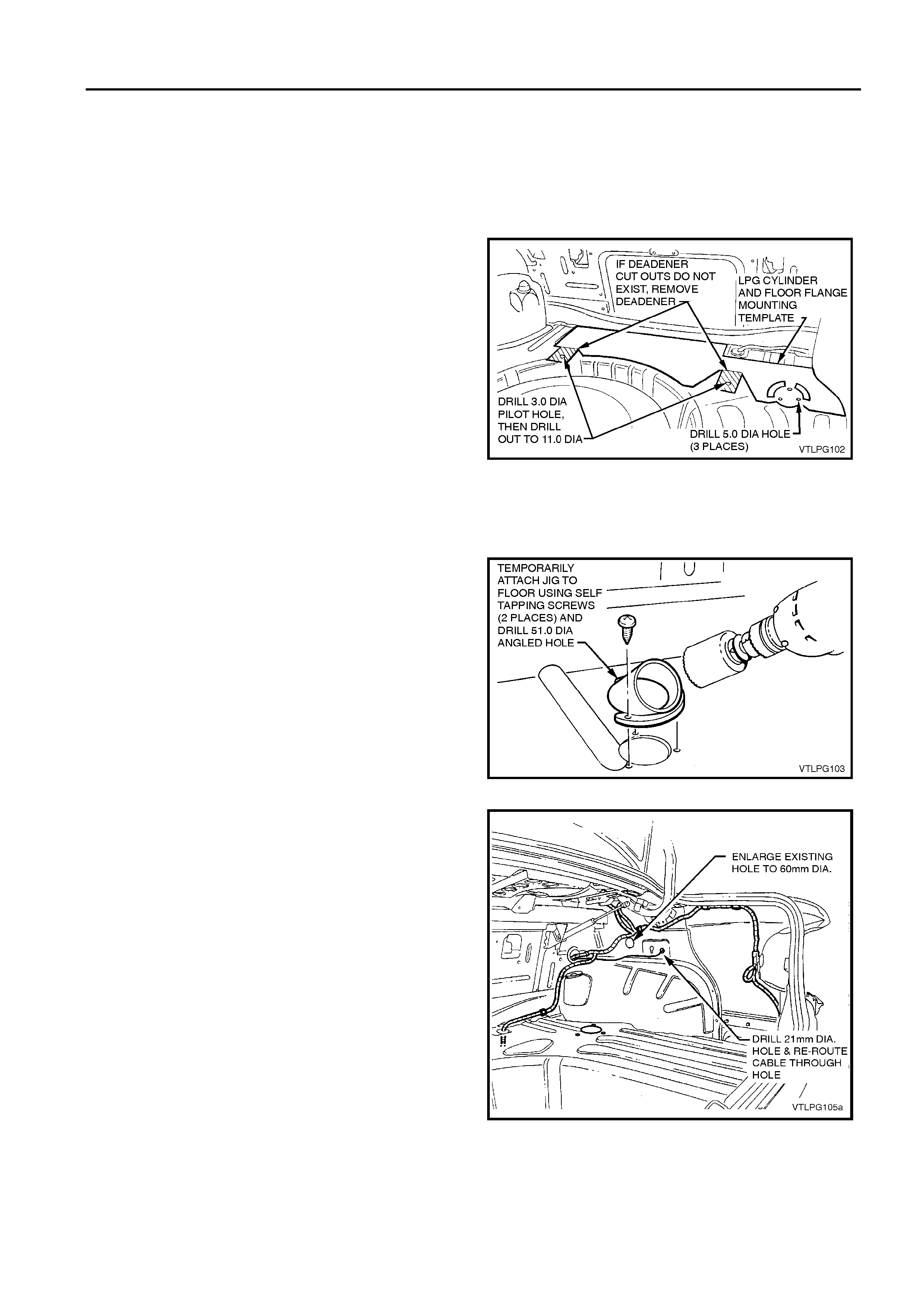
1. Where required, remove deadener from floor panel
using the template supplied to determine correct
location.
NOTE: Heat and soften deadener with a hot air gun to aid
removal.
2. Locate the dimples in the floor for positions of the two
tank mounting holes. Drill two 3.0 mm pilot holes
through the panel, and then drill each hole out to
11.0 mm.
NOTE 1: Care must be taken when drilling the RHS tank
mounting hole in the rear floor as there is a wiring loom
located directly beneath the drilling location. Use a drill
spacer or other means to limit the depth of the drill travel.
NOTE 2: If dimples do not exist, use template to mark two
tank mounting hole positions.
3. Apply anti-corrosion compound meeting HOLDEN Ltd
Specification HN1071 around perimeter of all holes
drilled in rear floor panel and allow to cure.
Figure 1-1
4. Mark and drill three 5.0 mm holes for mounting floor
flange. Use template to determine position.
5. Using drilling jig special tool, drill the 51.0 mm angled
hole in the rear floor panel.
6. Apply anti-corrosion compound meeting HOLDEN Ltd
Specification HN1071 around perimeter of all holes
drilled in rear floor panel and allow to cure.
Figure 1-2
7. Drill 21.0 mm hole in side panel as shown. Location is
determined by the existing marking on panel.
8. Remove fuel filler door remote cable from existing hole
and re-route through new hole.
9. Enlarge existing hole in side panel (formerly used for
fuel filler door cable) as shown, to 60.0 mm.
10. Apply anti-corrosion compound meeting HOLDEN Ltd
Specification HN1071 around perimeter of all holes
drilled in rear side panel and allow to cure.
NOTE: Limit drilling depth when drilling the 60.0mm hole
through inner side panel to avoid damage to outer side
panel.
Figure 1-3
1-6 LPG INSTALLATION INSTRUCTIONS
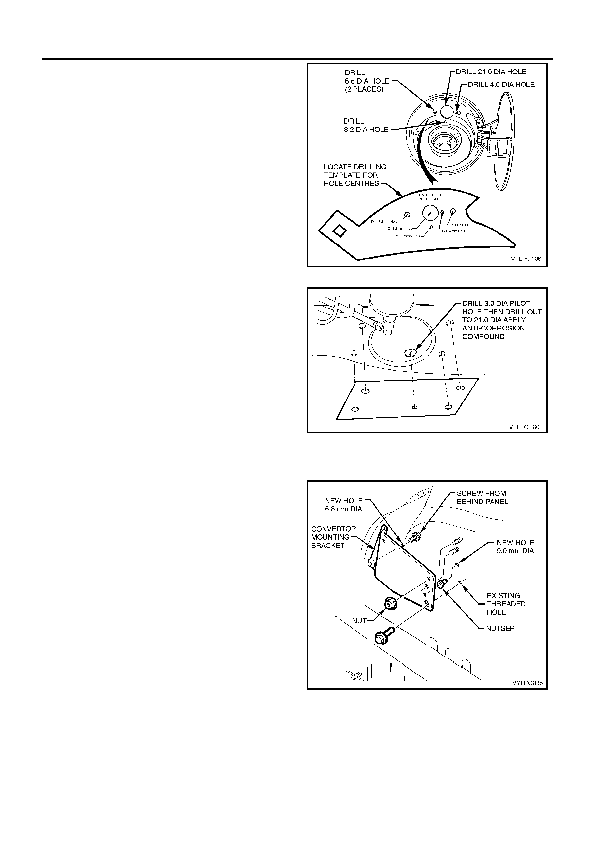
11. Using the template to determine the locations, drill holes
in top of the fuel filler pocket as shown.
12. Apply anti-corrosion compound meeting HOLDEN Ltd
Specification HN1071 around perimeter of all holes
drilled in fuel filler pocket and allow to cure.
Figure 1-4
13. Using template supplied, mark position of rear service
line hole in chassis rail, and drill 3.0mm pilot hole. Drill
out to 21.0mm using hole saw.
14. Apply anti-corrosion compound meeting HOLDEN Ltd
Specification HN1071 around perimeter of holes.
Figure 1-5
1.6 ENGINE BAY PREPARATION
1. Using the converter bracket as a template, drill a 9.0
mm hole in the wheelhouse as indicated. Fit the
supplied nutsert into the hole.
2. Using the converter bracket as a template, drill a
6.8 mm hole as indicated.
3. Apply anti-corrosion compound meeting HOLDEN Ltd
Specification HN1071 around perimeter of all holes
drilled in wheelhouse and allow to cure.
Figure 1-6
LPG INSTALLATION INSTRUCTIONS 1-7
1.7 LPG HARNESS INSTALLATION
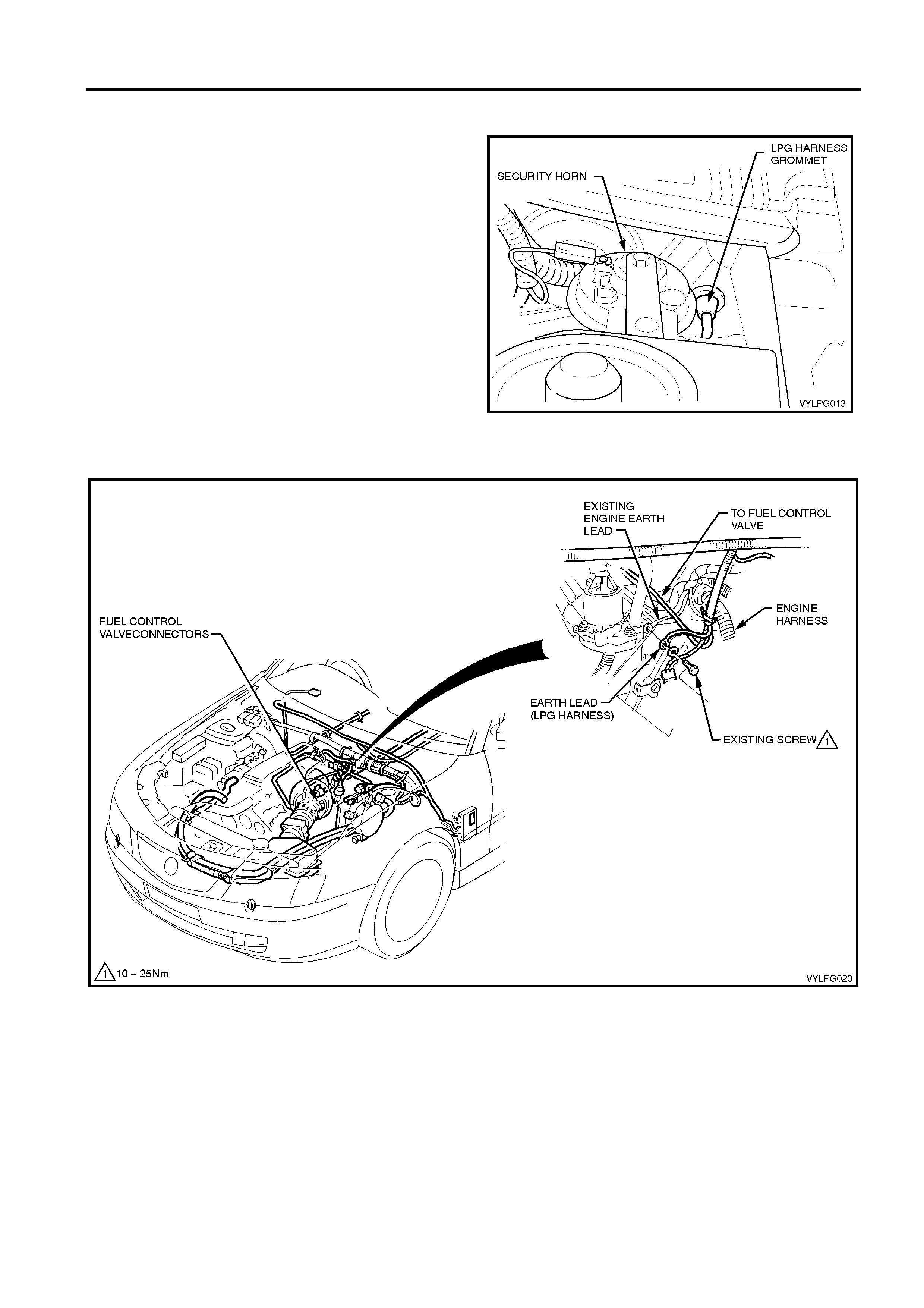
1. From within the occupant cabin, remove the existing
grommet installed in the far left-hand side of the dash
panel and insert the engine section of the LPG harness
through the existing grommet in the dash panel. Pull
through the harness from the engine compartment side
of the dash panel until the extended throat of the
harness grommet pulls through and engages into place
around the hole, refer to Figure 1-7.
2. Route the engine compartment section along the top
edge of the cockpit module, underneath the existing
main wiring harness.
3. Insert the LPG harness to the existing wiring harness
clips on the RHS (2 places) and tie strap the harness to
existing harness LHS (3 places) as shown in Figure 1-8.
4. Install the LPG engine earth lead to the existing harness
earth lead at the rear of the LHS cylinder head. Tighten
retaining bolt to 10 – 25 Nm.
5. Route the LPG harness fuel control valve connector to
the fuel control valve location ready for connection.
Figure 1-7
Figure 1-8
1.8 LPG HARNESS INTERIOR ROUTING
& FUEL MODE SWITCH INSTALLATION
Refer to Figure 1-9 for the following:
1. Install the interior section of the LPG harness from the
PCM connections (behind LHF lower side trim) towards
the RHF hinge pillar trim, routing behind the instrument
panel.
2. Feed the fuel mode switch connector and lead around
from behind the console and position along the right
hand side of the transmission tunnel, up to where the
auxiliary switch bezel is positioned.
3. From the RHS front hinge pillar, feed the yellow LPG
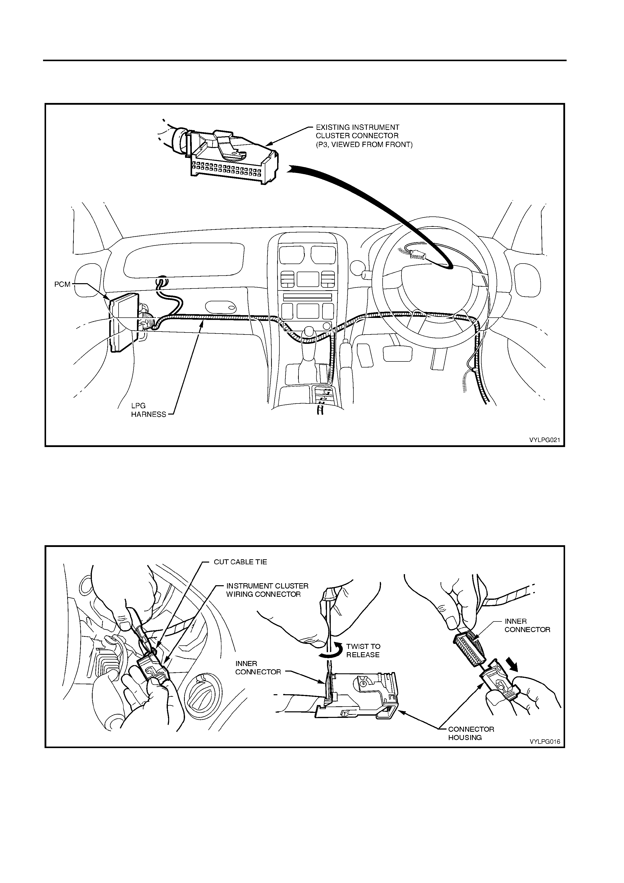
1-8 LPG INSTALLATION INSTRUCTIONS
harness to instrument cluster lead up behind the
instrument panel and alongside the existing instrument
cluster harness to the instrument cluster connector.
Figure 1-9
Refer to Figure 1-10 for the following:
4. Carefully remove the instrument cluster harness cable
tie using a pair of side cutters.
5. Prise the inner connector free from the connector
housing using a flat blade driver and using a twisting
action to lever it free.
Figure 1-10
LPG INSTALLATION INSTRUCTIONS 1-9
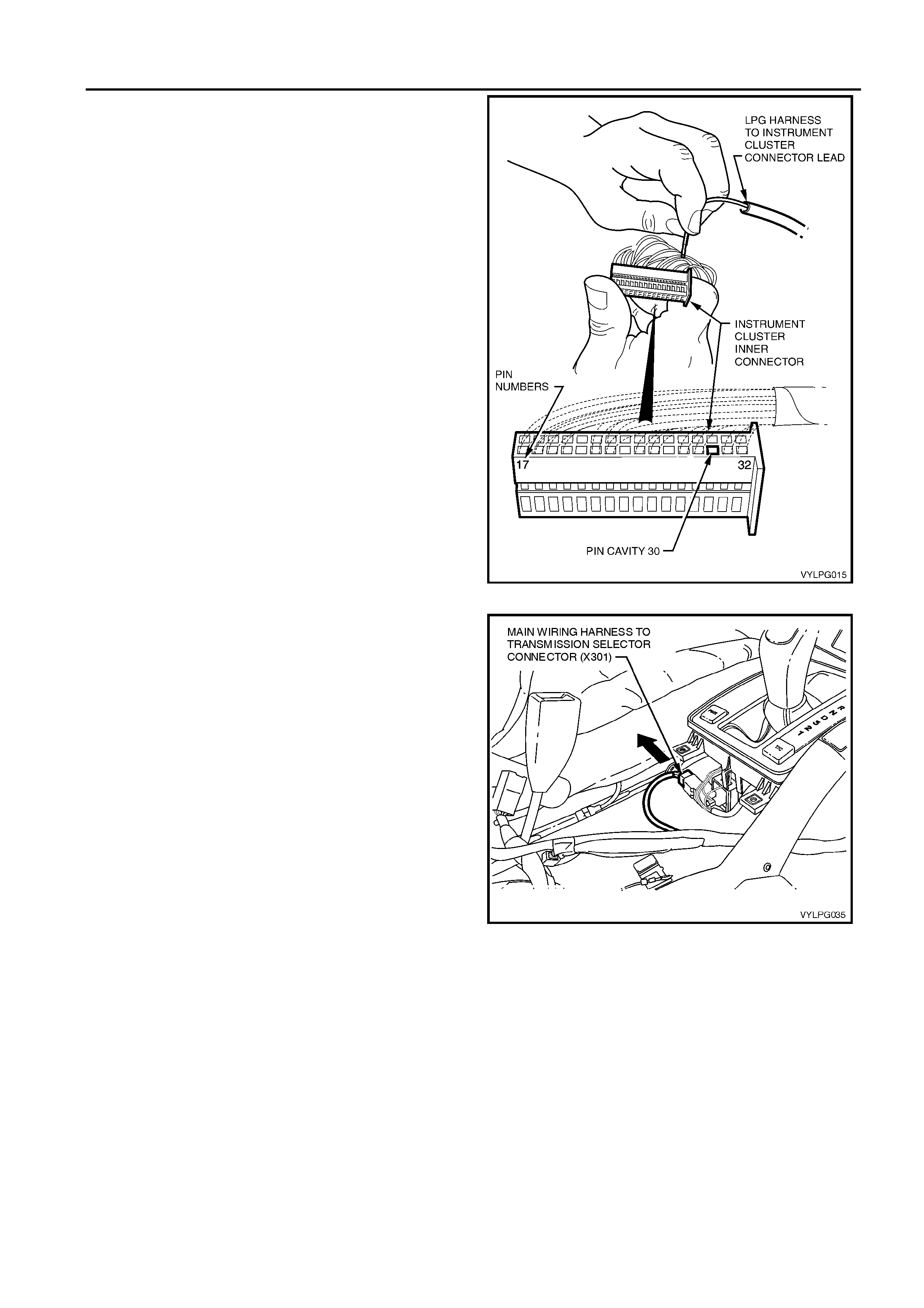
6. Determine the pin numbering sequence on the inner
connector (stamped on the side of the connector body)
and insert the yellow LPG harness to instrument cluster
lead terminal into pin cavity 30 (LPG sender) refer to
Figure 1-11.
7. Ensure the wire is securely fitted, then reassemble the
inner connector to the housing connector and secure
wires with a cable tie.
8. Reconnect the instrument cluster connector to the
instrument cluster and reinstall the instrument cluster,
refer to Section 1A3 in the VY and V2 Series Service
Information.
Figure 1-11
9. Unclip the main wiring harness to transmission selector
connector X301, refer to Figure 1-12.
Figure 1-12
1-10 LPG INSTALLATION INSTRUCTIONS
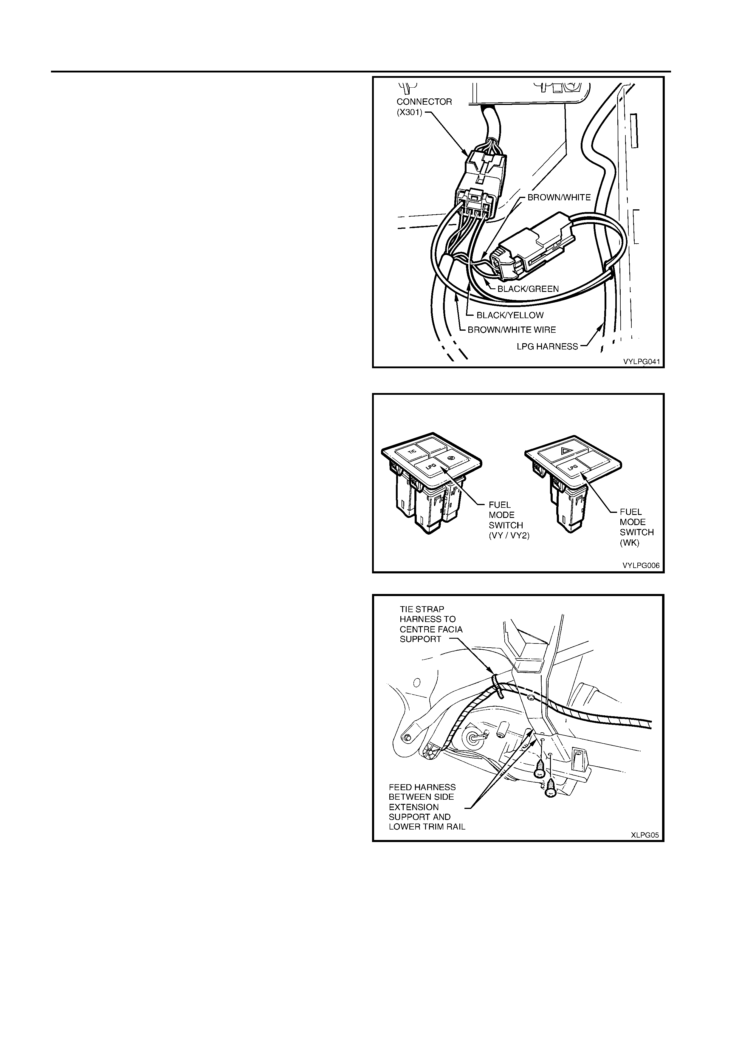
Refer to Figure 1-13 for the following:
10. From the back of the main wiring harness to
transmission selector connector X301, back out the
brown/white wire terminal from cavity 2 and the
black/green wire terminal from cavity 3 and insert these
terminals into cavities 1 and 2 respectively, of the sole
3-pin male LPG harness connector.
11. Insert the brown/white flying wire terminal and the
black/yellow flying wire terminal from the LPG harness
into the now vacant cavities 2 and 3 respectively of the
main wiring harness to transmission selector connector.
12. Reconnect each of the connectors.
13. Make any necessary adjustments to the LPG harness
positioning along the transmission tunnel, and install the
floor console back over the transmission selector.
Figure 1-13
14. Install the new fuel mode switch into the bottom LHS
cavity of the auxiliary switch liner in the floor console
cover, along with the original switches, as shown in
Figure 1-14. Install the new auxiliary switch bezel, as
supplied with the LPG installation kit, over the top of the
auxiliary switches and clip into place over the liner.
15. Hold the floor console cover assembly over the floor
console and connect the fuel mode switch patch
harness connector and the other connectors to their
respective switches.
Figure 1-14
16. Remove the two screws securing the lower RHS trim rail
to the centre facia side extension support.
17. Feed the harness between the lower trim rail and the
centre facia side extension support and position it
behind the centre facia side extension support as shown
in Figure 1-15. Tie strap the harness to the centre facia
support.
Figure 1-15
LPG INSTALLATION INSTRUCTIONS 1-11
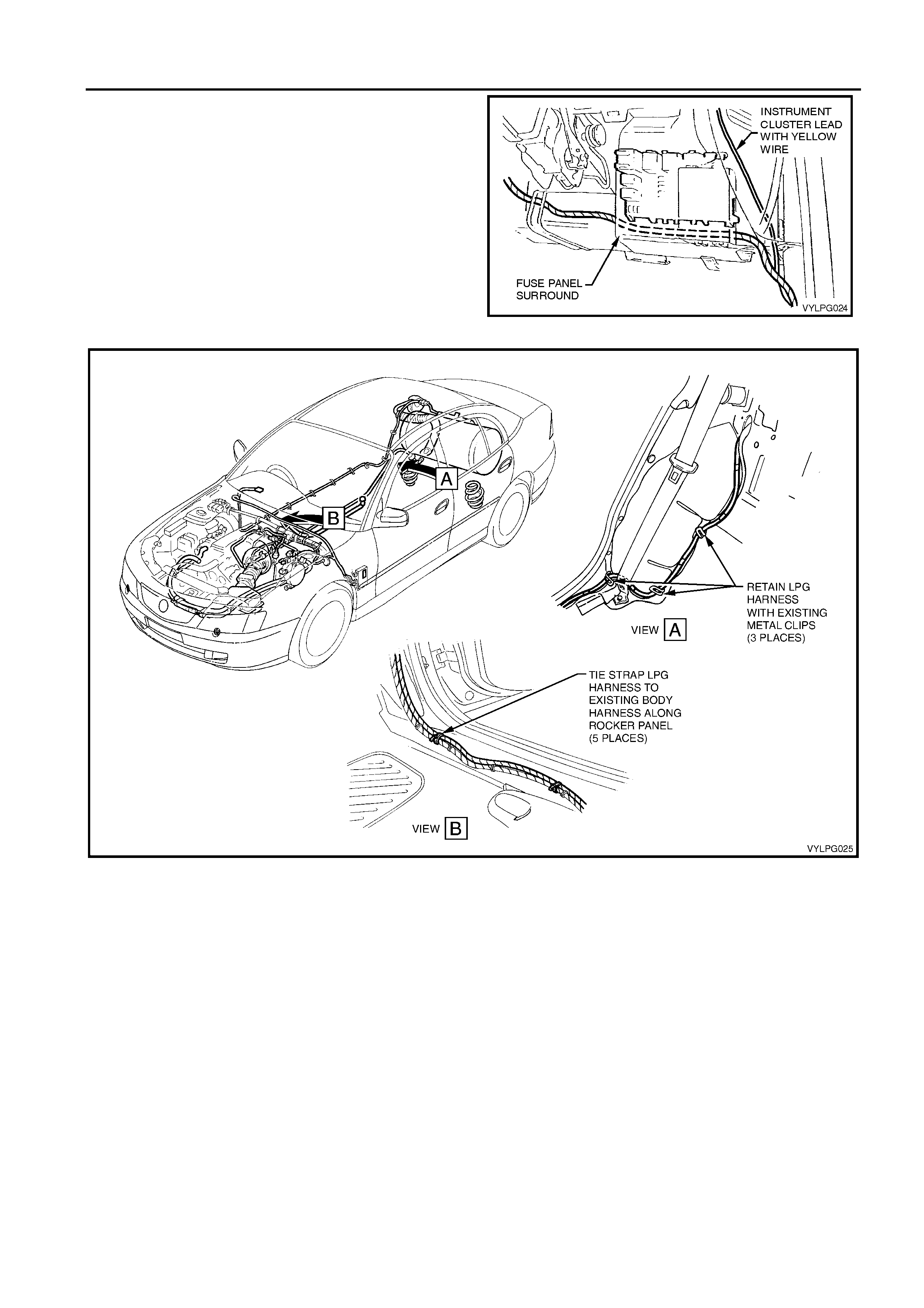
18. Route the harness behind the fuse block so that the
protective sleeve locates in behind the fuse block.
Refer to Figure 1-17 for the following:
19. Route the harness behind the RHS hinge pillar trim,
along the RHS side sill trim and around the inner rear
wheel arch and through the existing body harness
retaining clips.
20. Cable tie the harness to the existing body harness, at
five places along the door sill.
21. Feed the harness through the large hole in the body,
into the rear compartment, ready for connection to the
LPG cylinder anti-theft harness.
Figure 1-16
Figure 1-17
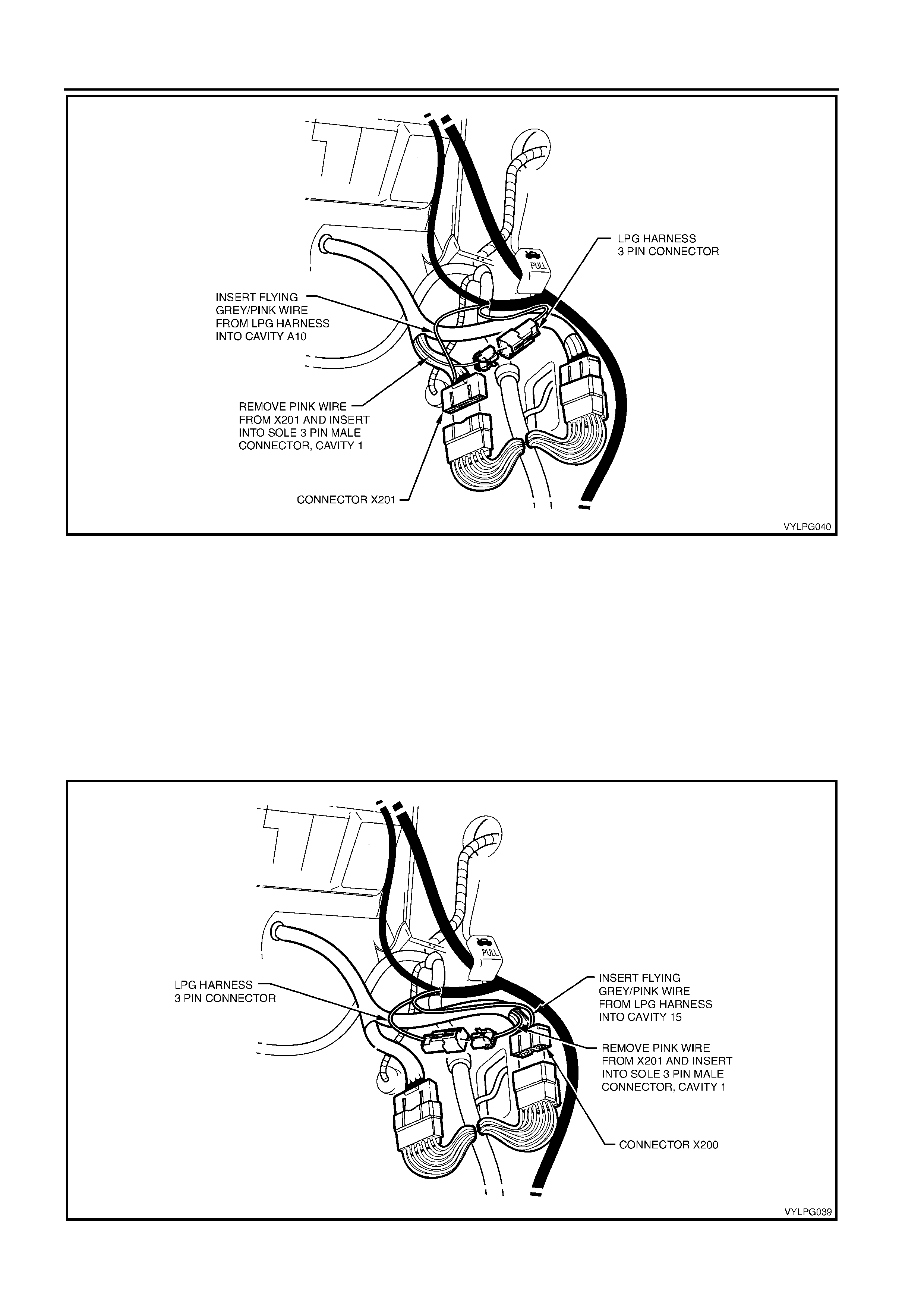
22. For VY vehicles, referring to Figure 1-18:
a. At the RHS hinge pillar, disconnect the main wiring
harness to the body wiring harness connector X201
and back out the Pink wire from cavity A10 and
connect this into cavity 1 in the back of the sole
three pin male connector, supplied with the LPG
installation kit.
b. Connect the Grey / Pink flying lead from the LPG
harness into the now vacant cavity A10 of
connector X201.
c. Connect the 3-pin male connector into the 3-pin
LPG harness connector and reconnect the main
wiring harness to body wiring harness connectors
X201.
1-12 LPG INSTALLATION INSTRUCTIONS
Figure 1-18
23. For VY2 and WK vehicles, referring to Figure 1-19:
a. At the RHS hinge pillar, disconnect the main wiring
harness to body wiring harness connector X200 and
back out the Pink wire from cavity 15 and connect
this into cavity 1 in the back of the sole three pin
male connector, supplied in the LPG installation kit.
b. Connect the Grey / Pink flying lead from the LPG
harness into the now vacant cavity A10 of
connector X201.
c. Connect the three pin male connector into the three
pin LPG harness connector and reconnect the main
wiring harness to body wiring harness connectors
X200.
Figure 1-19
LPG INSTALLATION INSTRUCTIONS 1-13
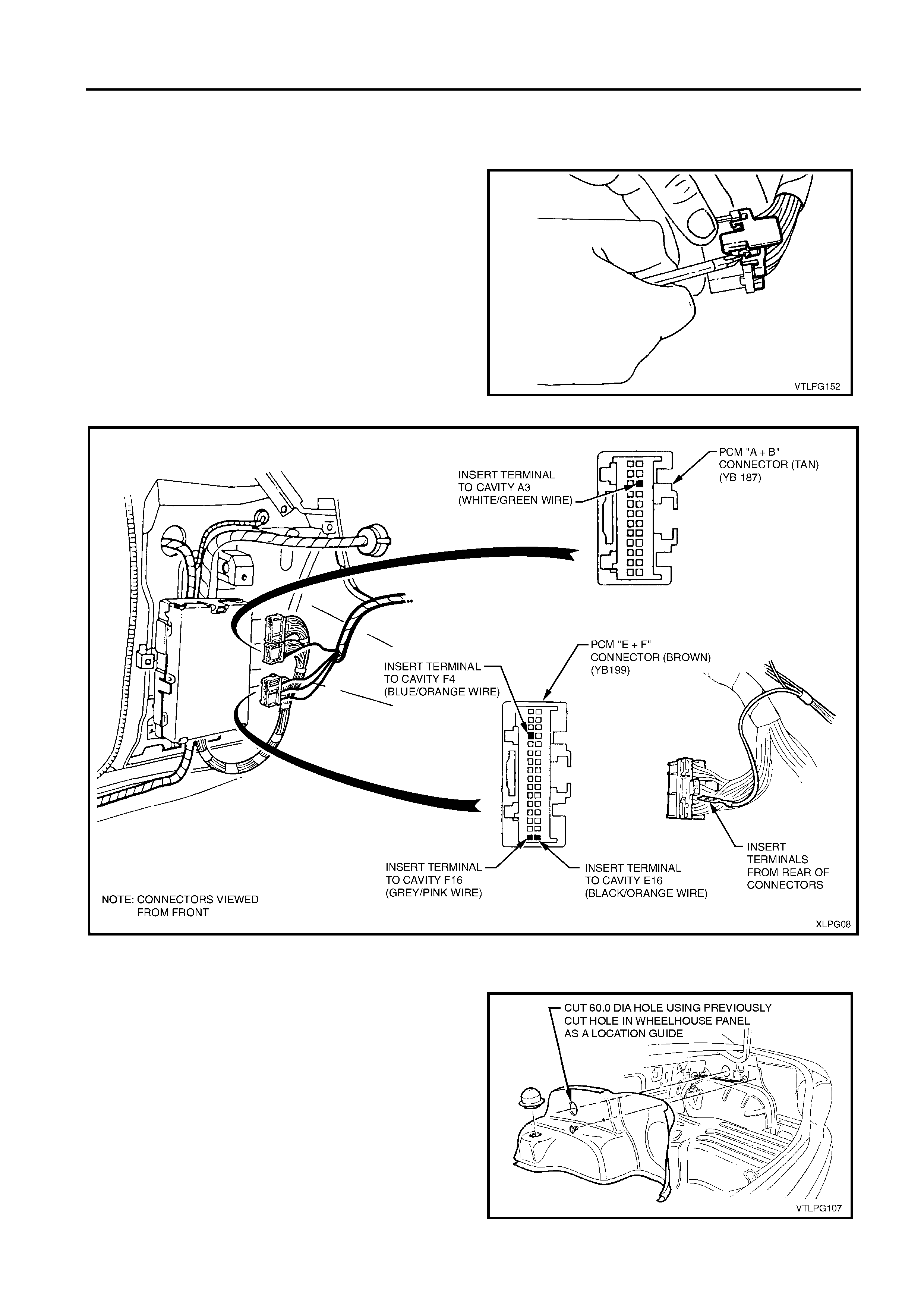
24. Make any necessary adjustments to the LPG harness
positioning, then return to the PCM location to make the
necessary connections to the PCM.
25. Remove the PCM and disconnect the wiring connectors.
26. Remove the covers from ‘E & F’ connector, (tan).
27. Remove covers from ‘A & B’ connector, (brown).
Figure 1-20
Figure 1-21
1.9 LPG CYLINDER INSTALLATION
1. Refit wheelhouse trim in position, and using the existing
60 mm hole in side panel as a guide, mark hole onto
trim. Remove trim and cut hole. Install grommet into
inner panel.
2. Refit the wheelhouse trim.
Figure 1-22

1-14 LPG INSTALLATION INSTRUCTIONS
3. Apply a bead of silicone sealer meeting HOLDEN Ltd
Specification HN1886 around the base of vent hose
flange.
4. Attach vent hose floor flange in position on RHS of rear
compartment floor using three rivets.
Figure 1-23
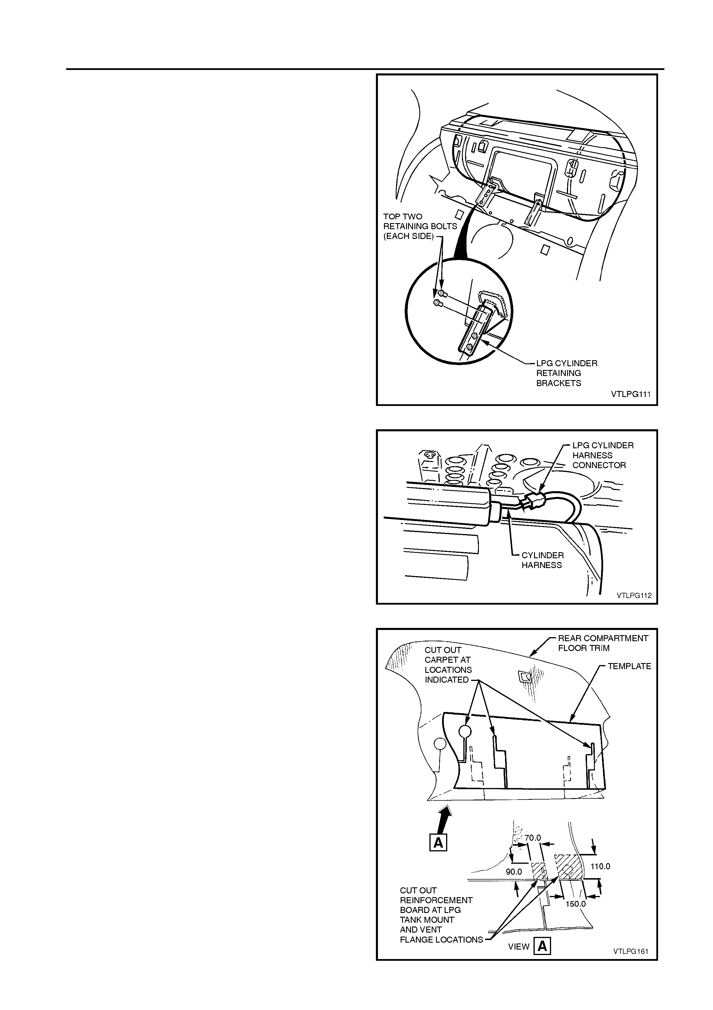
5. Place the LPG cylinder in position on rear compartment
floor panel and install the two rear cylinder retaining
bolts.
Figure 1-24
6. Install the two front brackets as shown.
7. Tighten all LPG cylinder-mounting bolts to the specified
torques.
LPG CYLINDER REAR RETAINING NUT
TORQUE SPECIFICATION 70 - 90 Nm
TANK BRACKET TO REAR FLOOR
RETAINING BOLT
TORQUE SPECIFICATION 25 - 35 Nm
TANK BRACKET T O LPG TANK
RETAINING BOLT
TORQUE SPECIFICATION 10 - 12 Nm
LPG INSTALLATION INSTRUCTIONS 1-15
6. Install the two front brackets as shown.
7. Tighten all LPG cylinder-mounting bolts to the specified
torques.
Figure 1-25
8. Connect the LPG cylinder anti-theft wiring harness to
the LPG harness.
Figure 1-26
9. Position the rear floor trim template onto the rear floor
trim and mark and trim carpet as shown in Figure 1-27.
10. From back side of trim, cut backing board away at tank
and vent hose floor flange locations as shown in Figure
1-27, View A.
11. Refit the rear floor trim.
1-16 LPG INSTALLATION INSTRUCTIONS
Figure 1-27
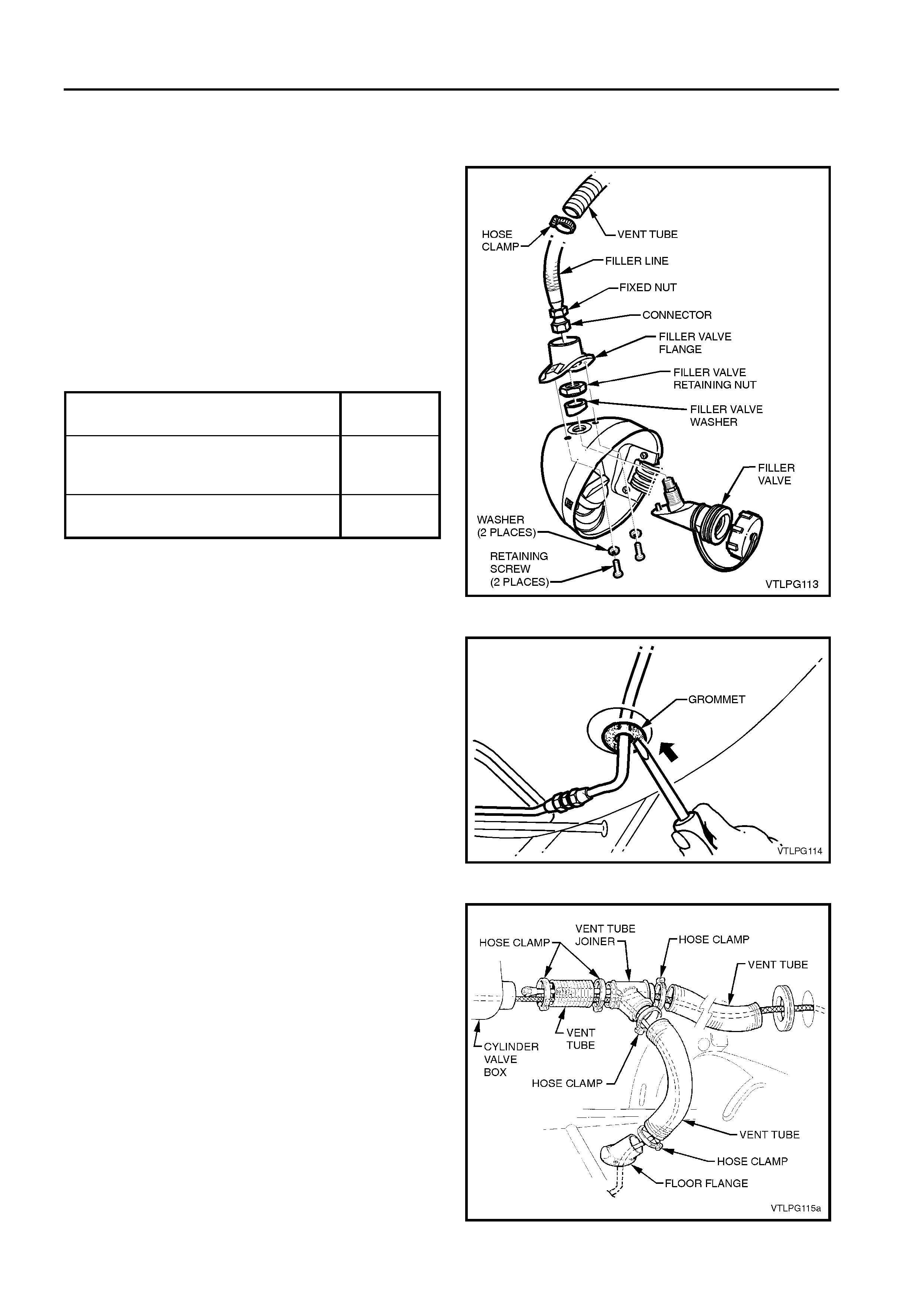
1.10 FILLER INSTALLATION
1. Install filler valve through hole in fuel filler pocket and
secure with nut and tapered spacer. Tighten nut to
specified torque.
2. Apply a bead of silicone sealer meeting HOLDEN Ltd
Specification HN1886 to the base of vent tube flange.
3. Install the filler vent tube flange to the fuel filler pocket.
Tighten the attaching screws to the specified torque.
4. Apply Loctite 577 sealant to filler valve threads and
attach the filler tube, tightening the fitting to the specified
torque.
5. Feed the filler tube through to the rear compartment.
Figure 1-28
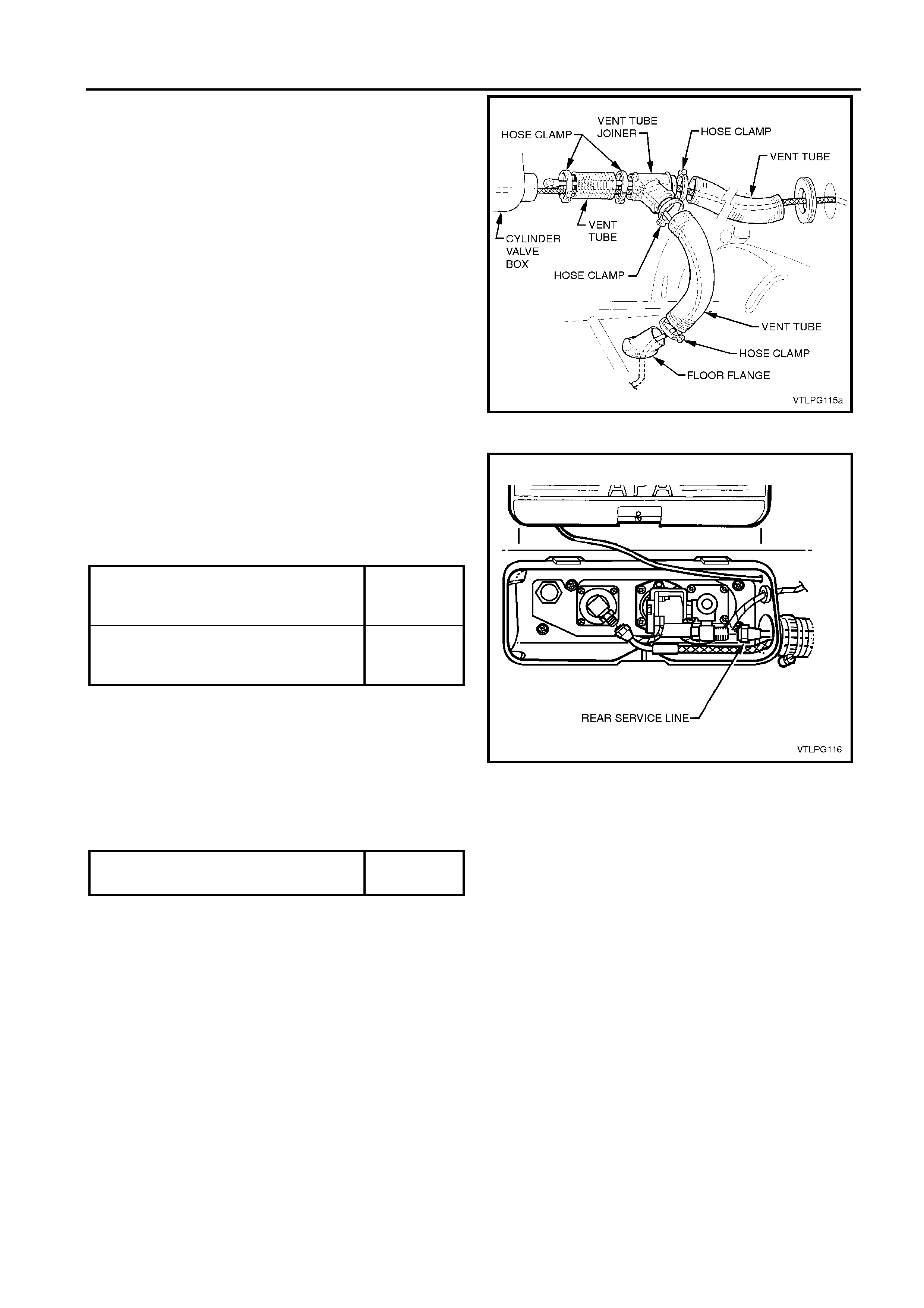
6. Install service line through vent hose flange and feed
through hole in rear longitudinal.
7. Refit service line grommet from underneath vehicle.
Figure 1-29
8. Install the vent tubes, clamps and joiner, piece by piece,
over the service line and filler tube, drawing the service
line and filler tube through into the cylinder valve box.
FILLER VALVE NUT
TORQUE SPECIFICATION 50 - 60 Nm
FILLER VENT TUBE FLANGE
RETAINING SCREW
TORQUE SPECIFICATION
25 - 35 Nm
FRONT SERVICE LINE CONNECTOR
TORQUE SPECIFICATION 10 - 12 Nm
LPG INSTALLATION INSTRUCTIONS 1-17
8. Install the vent tubes, clamps and joiner, piece by piece,
over the service line and filler tube, drawing the service
line and filler tube through into the cylinder valve box.
Figure 1-30
9. Apply Loctite 577 sealant to the AFL valve threads and
the filler valve
10. Ensuring the flared surfaces are free of sealer and
contaminates, attach the service line and the filler line,
tightening them to the correct torque specifications.
Figure 1-31
11. Tighten vent tube hose clamps to the correct torque
specification.
1.11 INTERMEDIATE SERVICE LINE
INSTALLATION
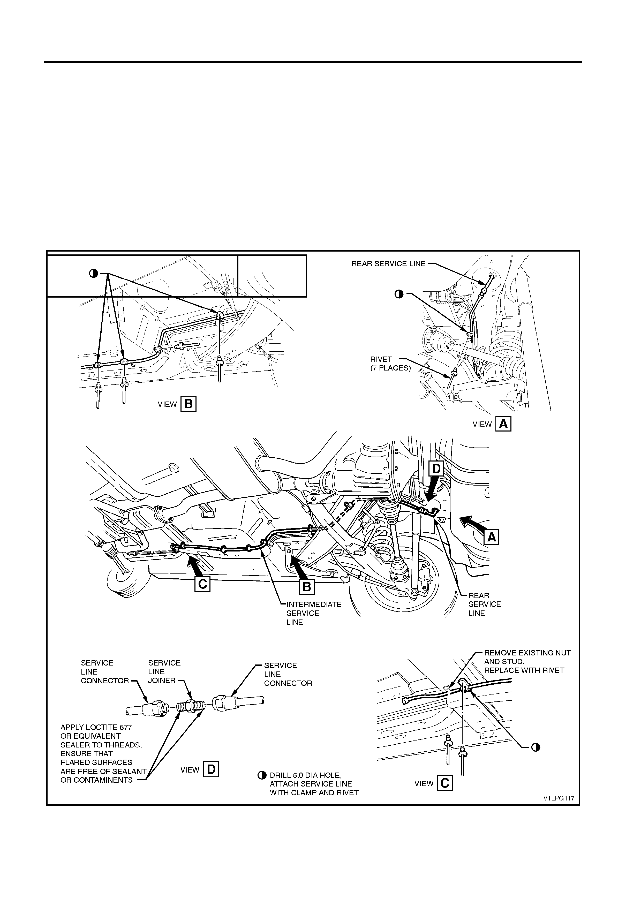
1. From underneath the vehicle, place the intermediate
service line in position, feeding the line from the front,
over the handbrake cable, rear suspension and axle
assembly.
2. Attach temporarily to rear service line as shown in
View A, Figure 1-32.
3. Attach service line to floor with mounting clamps
supplied. Drill 5 mm holes and rivet to rear floor in a
position as shown in View A, Figure 1-32.
4. Attach to rear floor in two places and alongside stone
shield in two places using clamps and rivets supplied, as
shown in View B, Figure 1-32.
5. Remove front inner nut and stud from stone shield and
replace with pop rivet to alleviate clearance problem
with service line. Attach service line to crossmember
with clamp and pop rivet as shown in View C, Figure
1-32.
FILLER LINE TO AFL VALVE
CONNECTION
TORQUE SPECIFICATION
12 - 18 Nm
REAR SERVICE LINE TO TANK
SERVICE VALVE
TORQUE SPECIFICATION
12 - 18 Nm
VENT TUBE HOSE CLAMP
TORQUE SPECIFICATION 1.0 - 3.0 Nm
1-18 LPG INSTALLATION INSTRUCTIONS
5. Remove front inner nut and stud from stone shield and
replace with pop rivet to alleviate clearance problem
with service line. Attach service line to crossmember
with clamp and pop rivet as shown in View C, Figure
1-32.
6. Disconnect intermediate service line from rear service
line at coupling.
7. Disconnect intermediate service line from rear service
line at coupling.
8. Apply Loctite 577 sealant to the intermediate to rear
service line joiner threads, ensuring the flared surfaces
are free of sealant and contaminants, refer View D,
Figure 1-32.
9. Reassemble the connections and tighten to the correct
torque specifications.
Figure 1-32
INTERMEDIATE SERVICE LINE TO
REAR SERVICE LINE
TORQUE SPECIFICATION
12 - 18 Nm
LPG INSTALLATION INSTRUCTIONS 1-19
1.12 FRONT SERVICE LINE
INSTALLATION
1. Remove the front right-hand side rail brace. Refer to
Section 1B in the MY 2003 VY and V2 Series Service
Information.
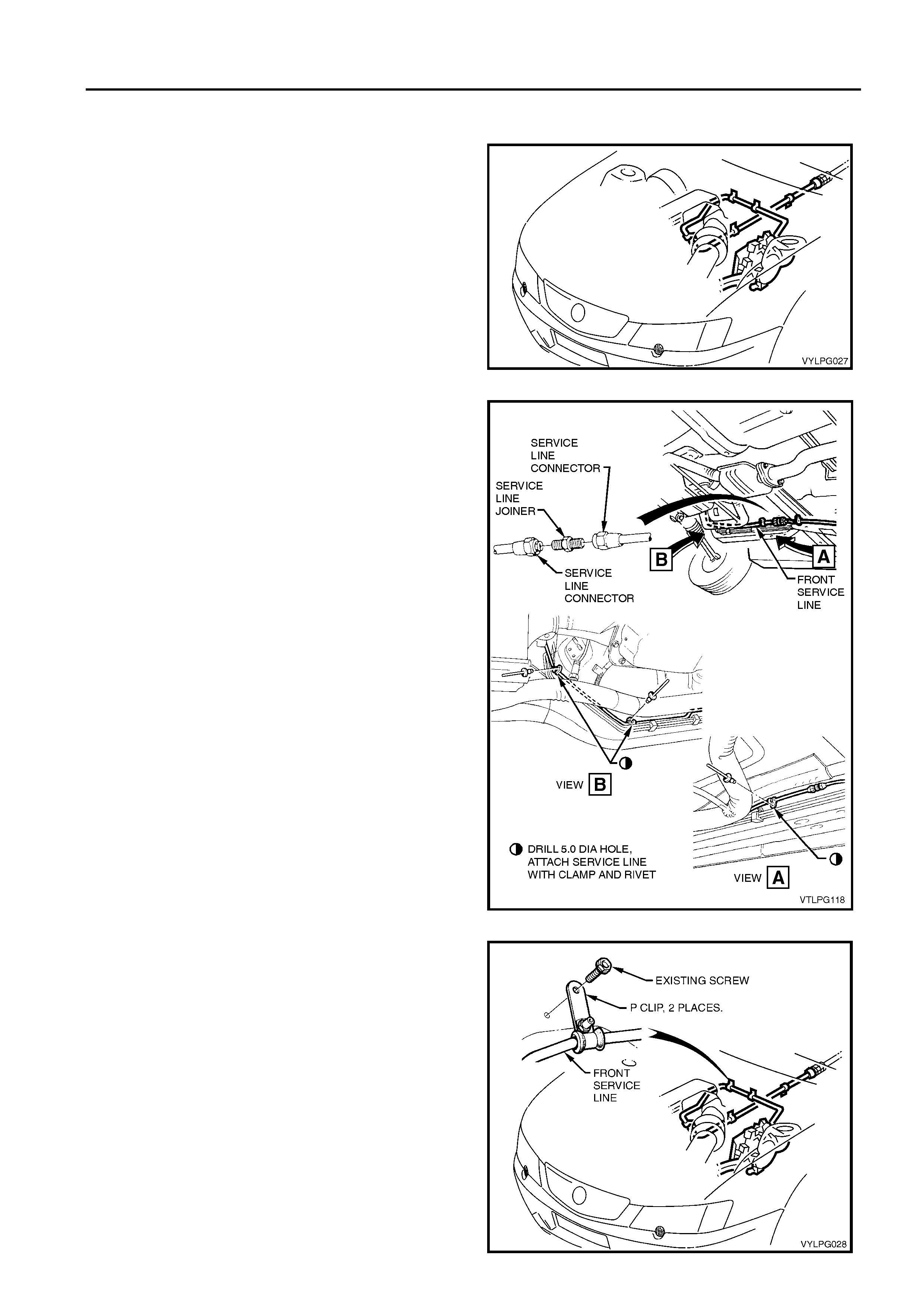
2. From under the vehicle, feed the front service line into
the engine compartment.
3. From above, position the front service line across the
rear of the engine compartment, to the LH side of the
engine compartment.
Figure 1-33
4. From under the vehicle, temporarily attach the front
service line to the intermediate line.
NOTE: VY underbody shown, installation of service line to
VY2 and WK underbody similar.
5. Attach the line to the longitudinal in two places and to
the front floor extension in one place as shown, using
clamps and pop rivets supplied.
Figure 1-34
6. Attach the front service line to the firewall in two places
as shown, using clips supplied and existing hardware.
1-20 LPG INSTALLATION INSTRUCTIONS
Figure 1-35
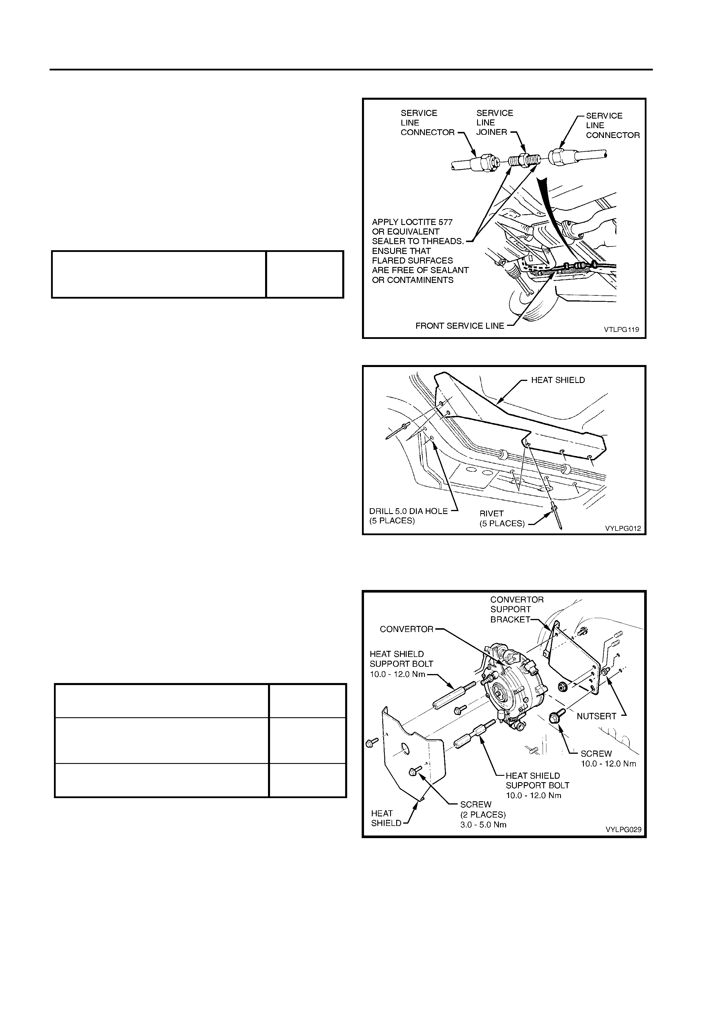
7. Disconnect front service line from intermediate service
line.
NOTE: VY underbody shown, installation of service line to
VY2 and WK underbody similar.
8. Apply Loctite 577 sealant to the front to intermediate
service line joiner threads, ensuring the flared surfaces
are free of sealant and contaminates.
9. Reconnect and tighten the connections to the correct
torque specifications.
Figure 1-36
10. Position the heat shield on vehicle as shown and mark
locations of mounting holes. Refer to Figure 1-37.
11. Drill 5 mm holes where marked (5 places).
12. Attach heats shield with rivets as shown.
13. Reinstall the right-hand side rail brace, refer to
Section 1B in the MY 2003 VY and V2 Series Service
Information.
Figure 1-37
1.13 CONVERTER INSTALLATION
1. Assemble converter mounting bracket and converter to
wheelhouse as shown.
2. Tighten all bolts and nuts to the specified torque.
3. Attach converter heat shield as shown and tighten the
two mounting screws and two support bolts to the
specified torque.
Figure 1-38
FRONT SERVICE LINE TO
INTERMEDIATE SERVICE LINE
TORQUE SPECIFICATION
12 - 18 Nm
CONVERTER MOUNTING BRACKET
SCREW TORQUE SPECIFICATION 10 - 12 Nm
HEAT SHIELD/CONVERTER
MOUNTING BOLT T O RQUE
SPECIFICATION 10 - 12 Nm
HEAT SHIELD MOUNTING SCREW
TORQUE SPECIFICATION 3.0 - 5.0 Nm
LPG INSTALLATION INSTRUCTIONS 1-21
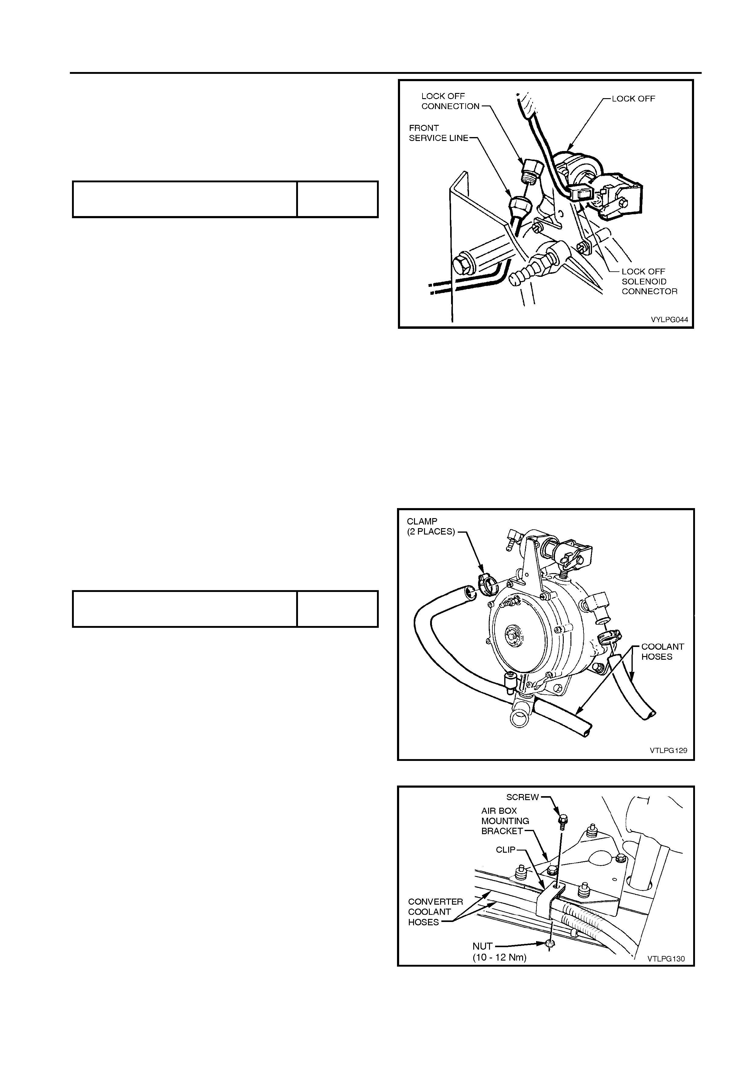
4. Apply Loctite 577 sealant to the front service line joiner
and lock-off valve inlet threads, ensuring the flared
surfaces are free of sealant and contaminates.
5. Tighten the connections to the correct torque
specifications.
6. Attach wiring harness connector to lock-off solenoid.
Figure 1-39
1.14 COOLANT HOSE INSTALLATION
1. Allow cooling system to cool to ambient temperature
(less than 50°c), then remove radiator cap.
CAUTION: DO NOT REMOVE RADIATOR CAP WHILE
THE ENGINE COOLANT TEMPERATURE IS ABOVE
50°C, AS PERSONAL INJURY MAY RESULT.
2. Place drain tray beneath vehicle.
3. Remove and discard coolant hose from heater valve to
engine coolant inlet.
4. Route coolant hoses from LPG converter. Route one
hose to engine coolant inlet and the other to heater
valve.
5. Fit hose clamps to the coolant hoses and tighten to the
correct torque specification.
Figure 1-40
6. Install the coolant hose with retaining bracket to existing
hole in the air cleaner mounting bracket using bolt and
nut provided. Refer Figure 1-41. Tighten nut to the
specified torque. Note convoluted protector shields on
coolant hoses.
NOTE: For this step to be completed, installation of the air
cleaner mounting bracket is required. Refer to
Operation 1.16 in this Section.
Figure 1-41
COOLANT HOSE CLAMP TORQUE
SPECIFICATION 3.0 - 4.0 Nm
FRONT SERVICE LINE TO LOCK-OFF
VALVE TORQUE SPECIFICATION 10 - 12 Nm
1-22 LPG INSTALLATION INSTRUCTIONS
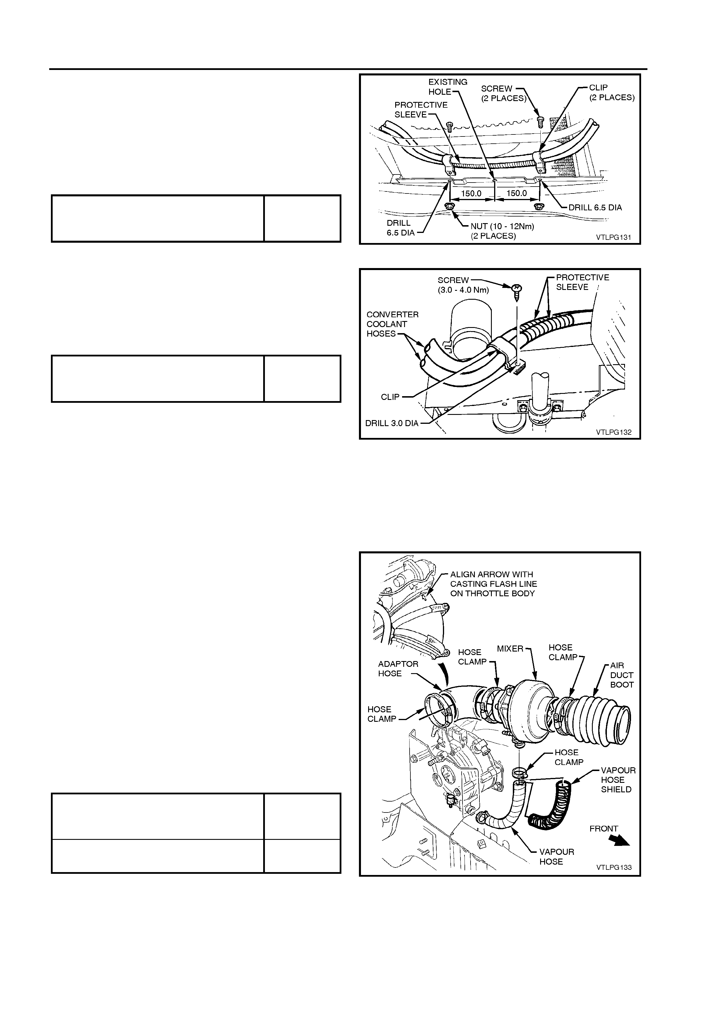
7. Mark the two coolant hose bracket retaining bolt hole
centres below the radiator in the front crossmember.
Each hole is located 150 mm from the centreline
(denoted by a hole in the crossmember). Drill two 3.5
mm holes at these points.
8. Attach hoses, including convoluted protector shields as
shown. Screw brackets to front crossmember with self-
tapping screws, tightening to specified torque.
Figure 1-42
9. Position coolant hoses in retaining bracket on the RHF
longitudinal in the position shown. Refer to Figure 1-43.
Drill 3.5 mm hole in longitudinal and attach retaining
bracket with self-tapping screw as shown. Tighten screw
to the correct torque specification. Note convoluted
protector shields on coolant hoses.
Figure 1-43
10. Check coolant hose routing to ensure hoses do not foul.
11. Fill, bleed and pressure test the cooling system. Refer to
Section 6B1 ENGINE COOLING - V6 ENGINE, in the
MY 2003 VY and V2 Series Service information.
1.15 MIXER INSTALLATION
1. Install the adaptor hose to the throttle body, aligning
arrow with casting mark on the throttle body. Install hose
clamp and tighten to specified torque.
2. Attach mixer to adaptor hose with vapour inlet facing
down. Install adaptor hose clamp and tighten so mixer
may still be rotated.
3. Place hose clamp over air duct boot and install air duct
boot to mixer assembly. Tighten hose clamp to the
correct torque specification.
4. Install vapour hose shield to vapour hose.
5. Position hose clamps on vapour hose, install vapour
hose onto mixer vapour inlet and converter vapour outlet
and tighten hose clamps.
6. Rotate mixer to obtain maximum clearance between
vapour hose and exhaust manifold, without kinking
vapour hose, so vapour inlet becomes approximately
10° off vertical.
Figure 1-44
ADAPTOR HOSE AND AIR DUCT BOOT
HOSE CLAMPS
TORQUE SPECIFICATION
3.0 - 4.0 Nm
VAPOUR HOSE CLAMPS
TORQUE SPECIFICATION 3.0 - 4.0 Nm
COOLANT HOSE BRACKET T O FRONT
CROSS MEMBER RETAINING SCREW
TORQUE SPECIFICATION
3.0 - 4.0 Nm
COOLANT HOSE BRACKET T O
LONGITUDINAL RETAINING SCREW
TORQUE SPECIFICATION
3.0 - 4.0 Nm
LPG INSTALLATION INSTRUCTIONS 1-23
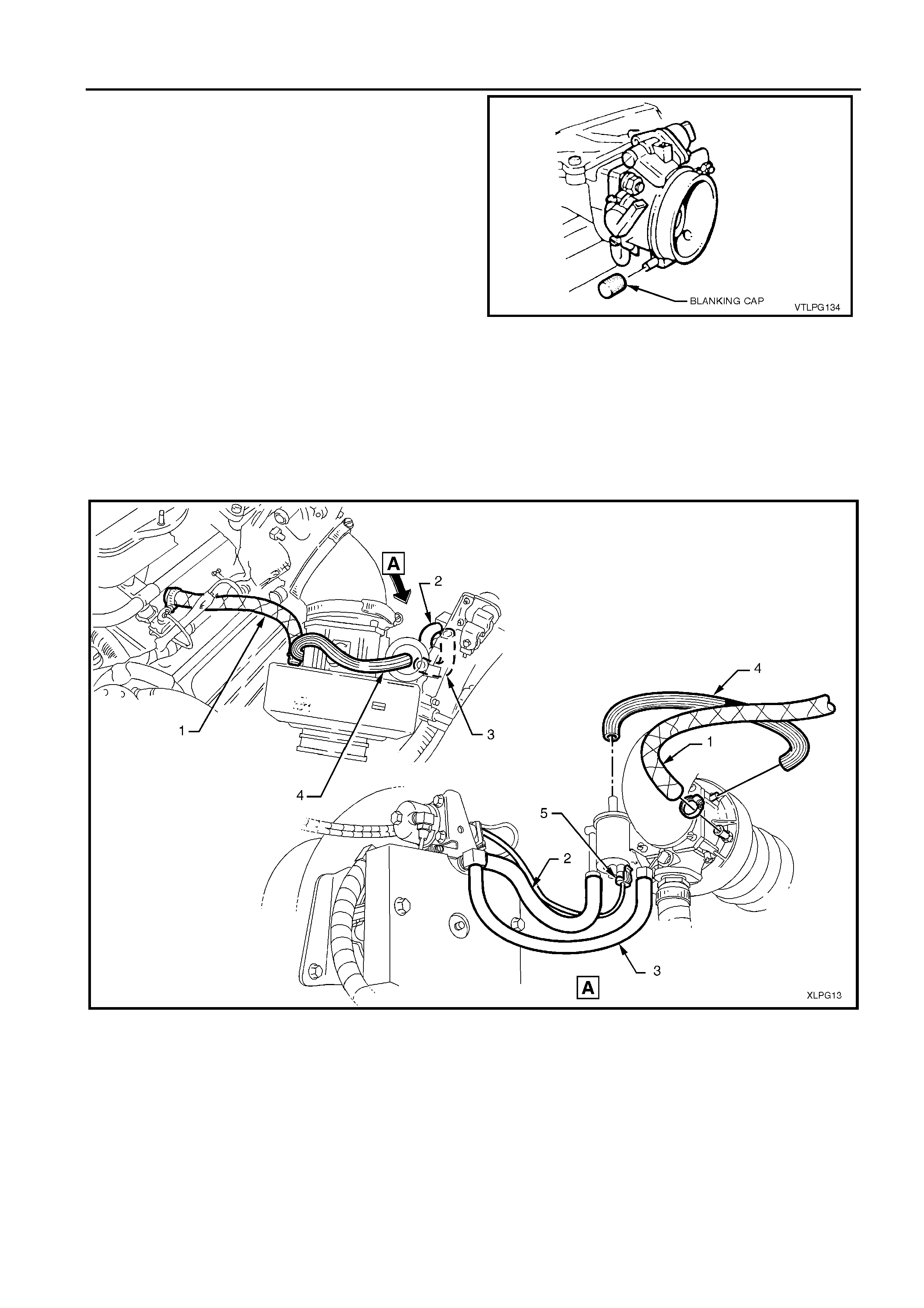
7. Remove crankcase breather from throttle body and
install blanking cap as shown.
Figure 1-45
8. Referring to Figure 1-46:
- Utilising the existing breather hose clamps, attach
the hose (1) between the mixer port and crankcase
breather port.
- Fit the vacuum hose between the FCV and converter
(2) and between the converter and mixer (3).
- Fit the balance hose (4) between FCV and mixer.
- Connect the FCV wiring connector (5).
Figure 1-46
1-24 LPG INSTALLATION INSTRUCTIONS
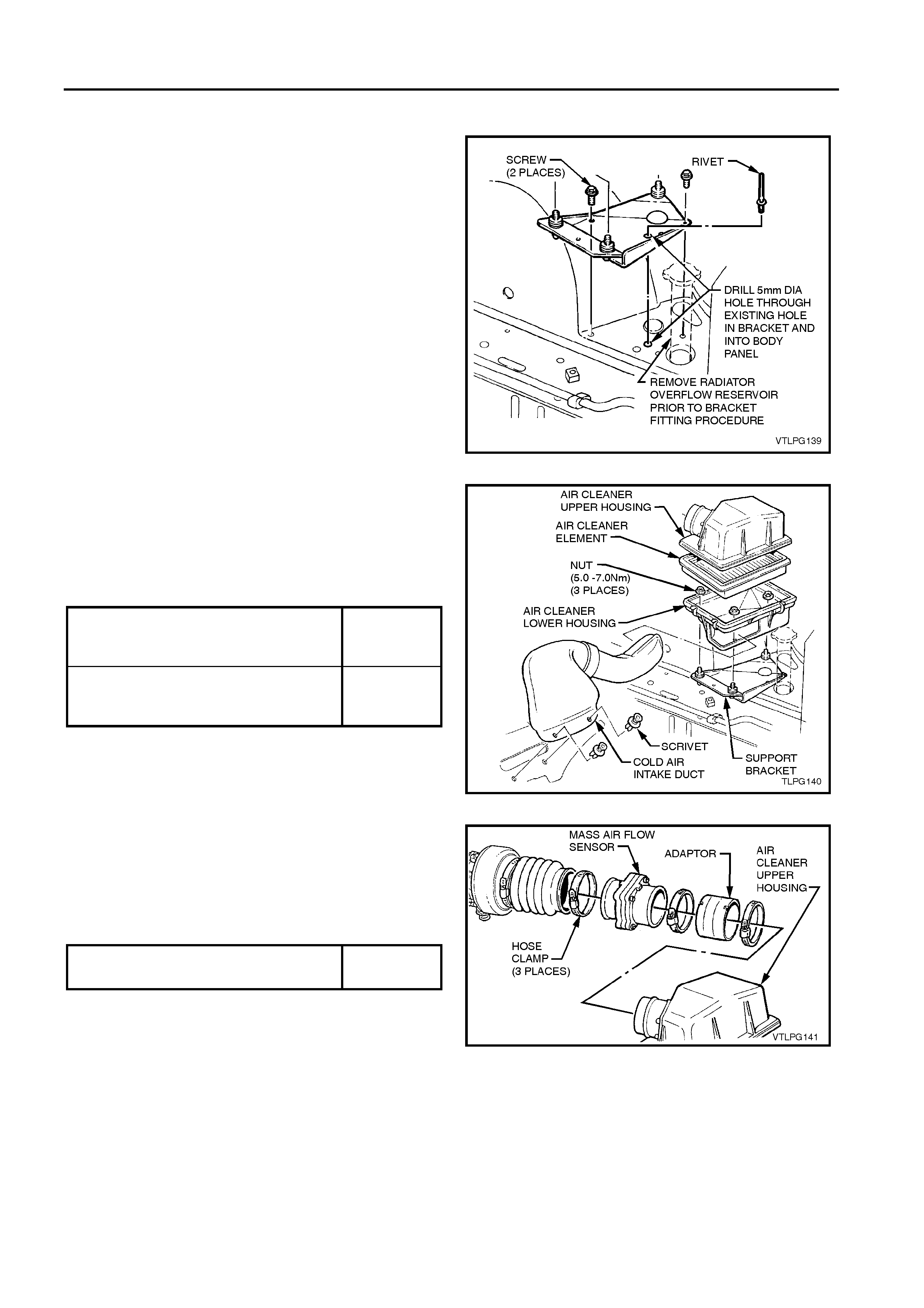
1.16 AIR CLEANER INSTALLATION
1. Attach air cleaner mounting bracket in place with
mounting bolts as shown, tightening to specified torque.
2. Drill 5.0 mm hole through existing hole in air cleaner
mounting bracket and into body panel as shown.
3. Install pop rivet in newly drilled 5.0 mm hole.
Figure 1-47
4. Install air cleaner lower housing as shown, tightening
retaining nuts to the specified torque.
5. Replace element in lower housing and clip the upper
housing in place.
6. Install cold air intake duct as supplied in kit. Attach in
two places with scrivets.
Figure 1-48
7. Assemble the air duct adaptor and mass airflow sensor,
tightening the hose clamp to the specified torque.
8. Place hose clamps on the adaptor and air duct boot and
install the mass airflow sensor between the air cleaner
and air duct boot.
9. Tighten the hose clamps to the specified torque.
Figure 1-49
AIR CLEANER MOUNTING BRACKET
RETAINING BOLTS
TORQUE SPECIFICATIONS.
3.0 - 5.0 Nm
AIR CLEANER BASE
RETAINING NUTS
TORQUE SPECIFICATION
5.0 - 7.0 Nm
AIR FLOW DUCT RETAINING HOSES
TORQUE SPECIFICATION 3.0 - 4.0 Nm
LPG INSTALLATION INSTRUCTIONS 1-25
1.17 REAR COMPARTMENT LID
EMERGENCY RELEASE CABLE
EXTENSION
As the LPG tank installation hinders access to the rear
compartment emergency release from within the rear
compartment, by law an extension must be added to provide
access to the release.
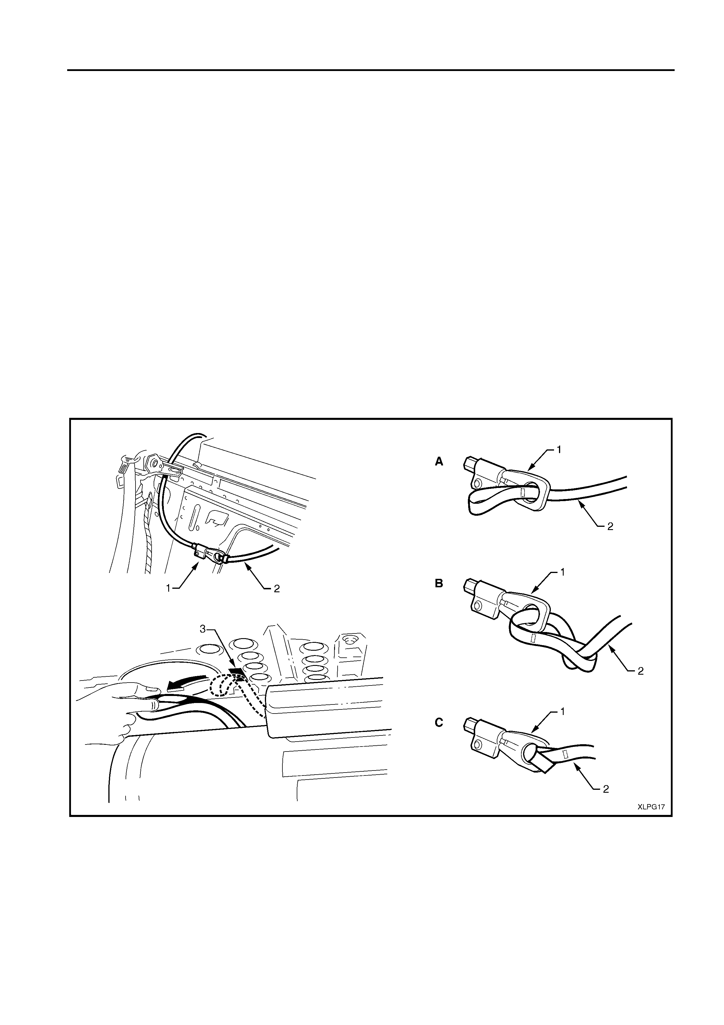
Referring to Figure 1-50:
1. Locate the rear compartment lid emergency release
cable end (1).
2. Pass one end of the extension (2) through the hole in
the cable end as shown A.
3. Pass the other end of the extension through the loop
and tighten as shown B & C.
4. Route the extension over the LPG tank.
5. From inside the rear compartment, apply the self-
adhesive Velcro strip (3) to the underside of the back
panel - upper.
6. Attach the extension to the Velcro strip.
7. Check the operation of the release by detaching the
extension and pulling it to the LH side.
8. Reattach the extension to the Velcro strip.
Figure 1-50
Legend
1. Rear compartment lid emergency release cable
assembly
2. Rear compartment lid emergency release cable
extension
3. Velcro strip
1-26 LPG INSTALLATION INSTRUCTIONS
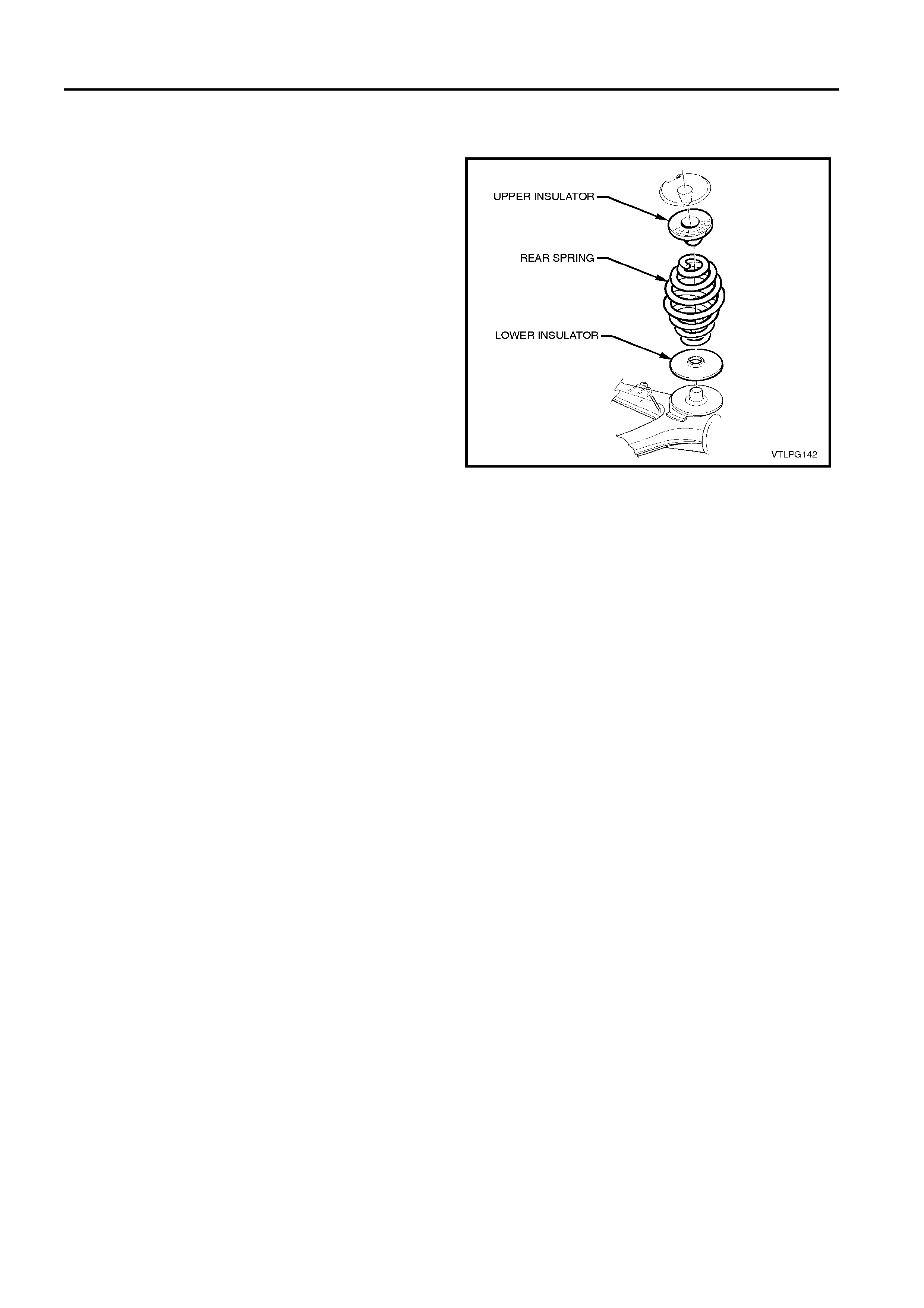
1.18 REAR SPRING AND SHOCK
ABSORBER INSTALLATION
For VY and VY2 vehicles, remove the rear springs and
replace with the new springs provided in the respective
installation kit. For VY vehicles, refer to Section 4A REAR
SUSPENSION, in the MY 2003 VY and V2 Series Service
Information. For VY2 vehicles, refer to Section 4A REAR
SUSPENSION, in the MY 2004 VY2 Series Service
Information.
For WK vehicles fitted with the level ride shock absorber
(option FX3), no spring or shock absorber replacement is
necessary. For WK vehicles not fitted with this option,
replace the existing springs and shock absorbers with those
provided in the installation kit, refer to Section 4A REAR
SUSPENSION, in the MY 2004 WK Series Service
Information.
Figure 1-51
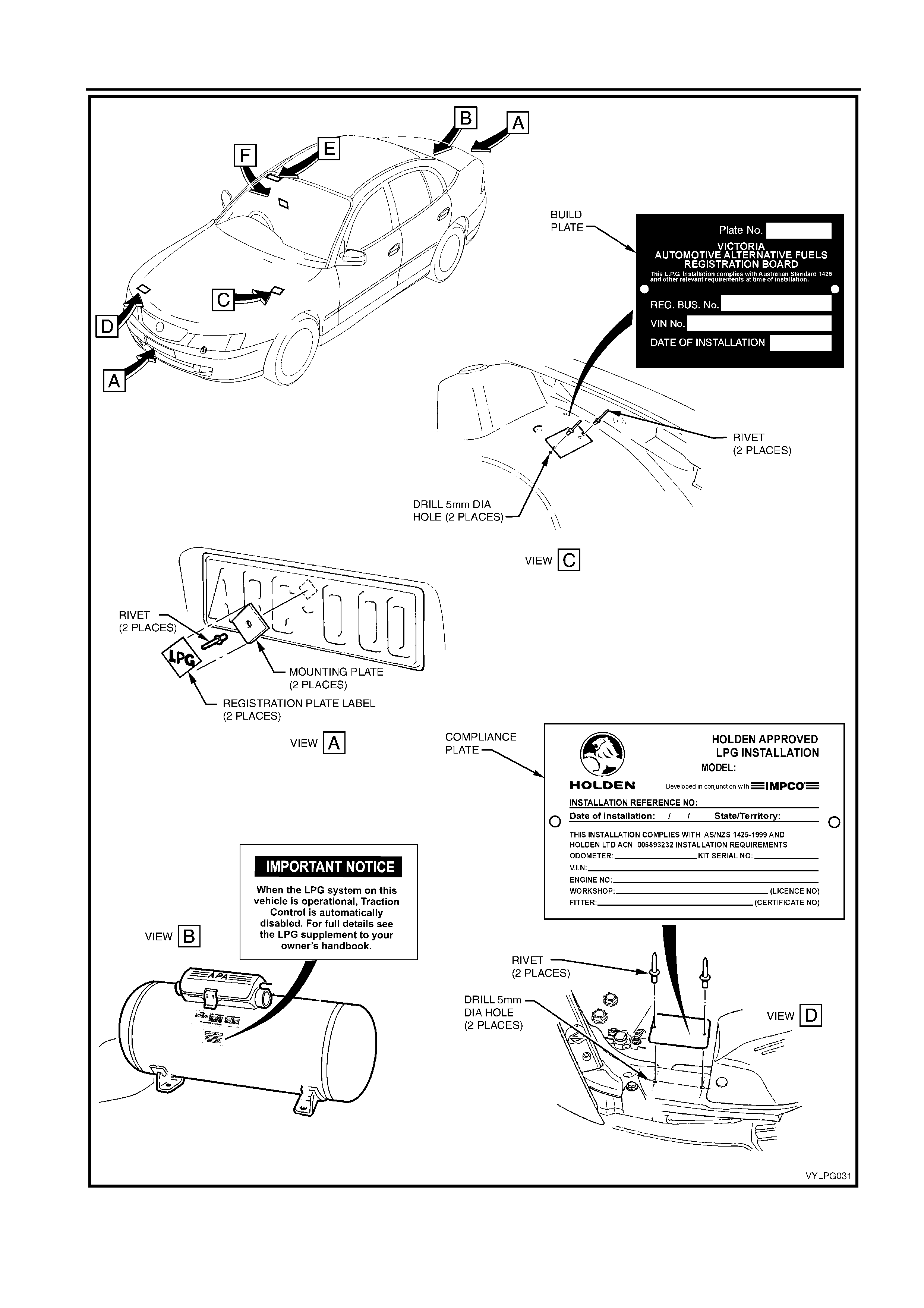
1.19 COMPLIANCE PLATES & ID.
LABELS – INSTALLATION
Referring to Figure 1-52, affix:
- Mounting plate and LPG label to middle of both front and
rear registration plates.
- “HOLDEN APPROVED LPG INSTALLATION” plate to
upper front panel using the template supplied.
- Compliance plate to LHF wheelhouse panel using the
template supplied.
- "IMPORTANT NOTICE" label to LPG cylinder, directly
below existing "APA" label.
NOTE: If the vehicle has not been registered, place the
registration plate mounting plates and labels in the glove box
with the warranty card and owners manual supplement.
LPG INSTALLATION INSTRUCTIONS 1-27
Figure 1-52

1-28 LPG INSTALLATION INSTRUCTIONS
Referring to Figure 1-53, affix:
- “LPG PRECAUTIONS FOR EFI” label to right-hand top
of windscreen.
- Tyre placard label to RHS front door panelling.
Figure 1-53
1.20 LEAK TEST
Perform the LPG leak test as described in Section 2 of these
installation instructions.
1.21 TECH 2 LPG SET-UP & ENABLE
PROCEDURES
Perform the procedures described in Section 3 of these
installation instructions to program the PCM for LPG and
enable the instrument cluster LPG indicator.
1.22 COMPONENT REINSTALLATION
Reinstall all other components removed in accordance with
the procedures outlined in the appropriate Sections in the
MY 2003 VY, MY 2004 VY2 and MY 2004 WK Series
Service Information.
1.23 AFTER INSTALLATION CHECK
CAUTION: To ensure that the LPG installation has been
carried out in accordance with these installation
instructions, an After Installation Check MUST be
performed.
The checklist is to be completed by the authorised fitting
technician and filed by the authorised fitting dealer. Refer to
Section 4 of these installation instructions.

LPG INSTALLATION INSTRUCTIONS 1-29
1.24 ENABLE THE SRS & AUDIO
SYSTEMS
The vehicle is equipped with OPS (Occupant Protection
System), incorporating the SRS (Supplemental Restraint
System). To enable the system, refer to 2.2 SYSTEM
DISABLING AND ENABLING PROCEDURE, ENABLING
THE OPS / SRS, in Section 12M of the MY 2003 VY and
VY2 Series Service Information.
Following the procedure in the vehicle owner’s manual,
reprogram the audio system with the four-digit security PIN
code.


LPG LEAK TESTING 2-1
SECTION 2
CAUTION:
This vehicle is equipped with a Supplemental Restraint System (SRS). A SRS will consist of either driver’s and
front passenger’s airbags, or driver's and front passengers airbags an d front occupant seat belt pre-tensioners,
or driver’s and front passenger’s airbags an d front occupan t left and right hand sid e airbags and front occup ant
seat belt pre-tensioners. Refer to CAUTIONS in Section 12M of the MY 2003 VY and VY2 Series Service
Information before performing any service operation on or around SRS components, the steering mechanism or
wiring. Failure to follow the CAUTIONS could result in SRS deployment, resulting in possible personal injury or
unnecessary SRS system repairs.
LPG LEAK TESTING
CONTENTS
Ref. Subject Page
2.1 GENERAL INFORMATION...................................2-1
2.2 COMBUSTIBLE GAS DETECTORS ....................2-2
2.3 FOAM....................................................................2-2
2.4 LEAK TEST PROCEDURE...................................2-3
2.1 GENERAL INFORMATION
The following leak test procedure is to be carried out on the
LPG system high pressure components and is to be
performed as part of the LPG installation. It is also to be
performed as part of each normal maintenance service.
For safety reasons the leak test must be carried out in the
open air, in a well ventilated area and PRIOR to bringing the
vehicle into the workshop after filling with LPG.
2-2 LPG LEAK TESTING
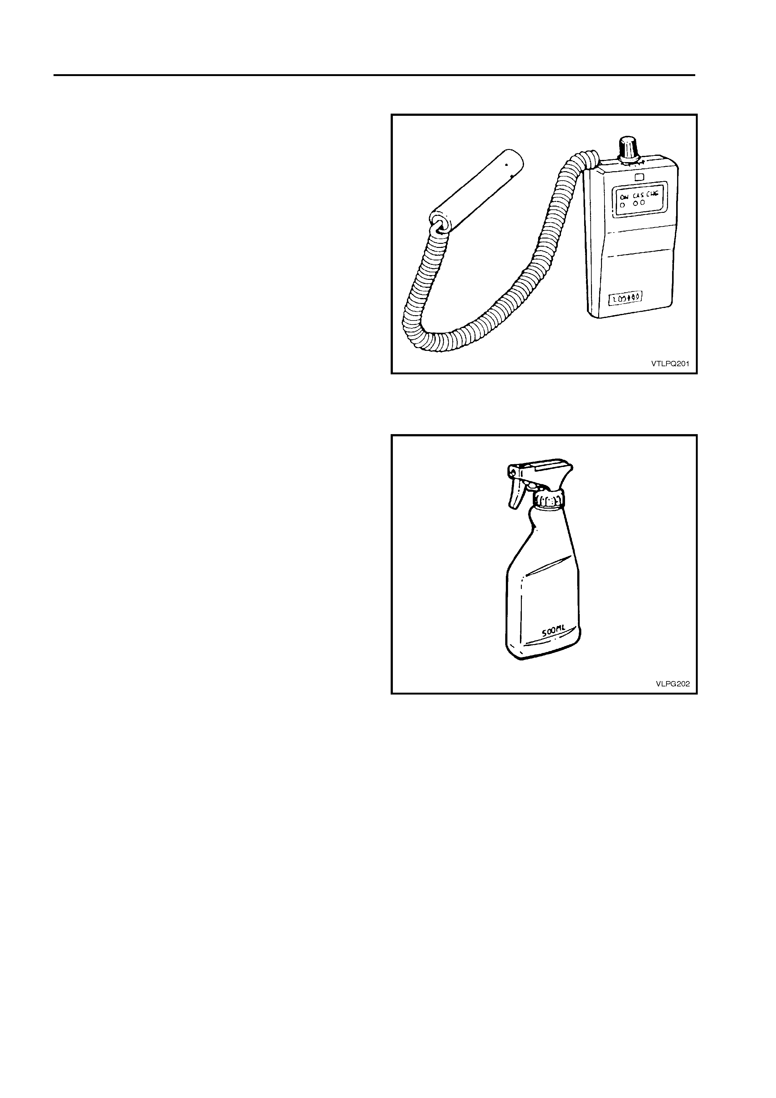
2.2 COMBUSTIBLE GAS DETECTORS
If a combustible gas detector, such as an LD-9001 LP Gas
leak detector or equivalent, is to be used for leak testing of
the LPG system, the combustible gas detector should be
capable of detecting 25 parts per million (PPM) of LPG in air.
A detector such as a LD-9001 LP Gas Leak Detector or
equivalent is recommended.
Whichever leak detector is used, it is important to follow the
manufacturer's instructions in regard to adjustment and
setting of the instrument prior to conducting the leak test.
Care in interpretation is necessary, as the detector can
respond to the presence of any of several vapours that are
combustible, some of which may not be LPG, such as oil
smears, joining compounds, etc. It may also detect residual
LPG vapours that are present for reasons other than
leakage, and which must be cleared before a valid test for
leakage can be made.
If a leak is present, a detector will signal its existence but not
its size. The detector will indicate its general location, but
may not be able to locate it exactly, so a follow up or proving
check with foam is often desirable.
Figure 2-1
2.3 FOAM
If foam is to be used, the foaming agent should be a
proprietary leak test solution, formulated specifically for the
purpose such as Gameco Leak Check ™ or a similar
solution. The solution should be fresh and the whole of the
area to be tested should be coated. Time should be allowed
for bubbles to form. All areas under test must be able to be
observed during the leak test.
Whichever foaming agent is used, it is important to follow the
manufacturer's instructions.
Foam testing is more effective for small leaks. Large leaks
tend to blow the solution away from the leak without forming
a bubble, so care in application is necessary.
The leak test is performed by directing a spray of solution at
each of the possible leak points in the high pressure side of
the system.
After the solution is applied, the area should be watched
carefully for no less than 15 seconds.
A leak is indicated by the presence of gas bubbles (foaming)
in the solution at the leak source.
NOTE: LPG is heavier than air, so testing should be carried
out thoroughly below all components and fittings.
If a leak is detected at a joint, the relevant component/s must
be removed as described in the appropriate component
service operation. Refer to 1 LPG INSTALLATION
INSTRUCTIONS in this Section. All mating threads should
be cleaned then resealed using the specified sealant and
tightened to the specified torque. Once installed, thoroughly
leak test the components again.
At the completion of each test, the leak test area of foaming
agent should be dried with low pressure compressed air or
shop cloths and the immediate area sprayed with a water
dispersing agent such as WD40, RP7 etc.
Figure 2-2

LPG LEAK TESTING 2-3
2.4 LEAK TEST PROCEDURE
With 3 litres of LPG in the LPG cylinder, leak test the complete LPG
system following the instructions below
1. Park the vehicle in a dry, well ventilated area.
CAUTION: Do not smoke or allow naked flames or any ignition
source near the vehicle during the testing operations.
2. Ensure the vehicle is operating on LPG and run the engine for at
least 30 seconds to fully pressurise the system, then stop the
engine.
3. The recommended sequence of testing is as follows:
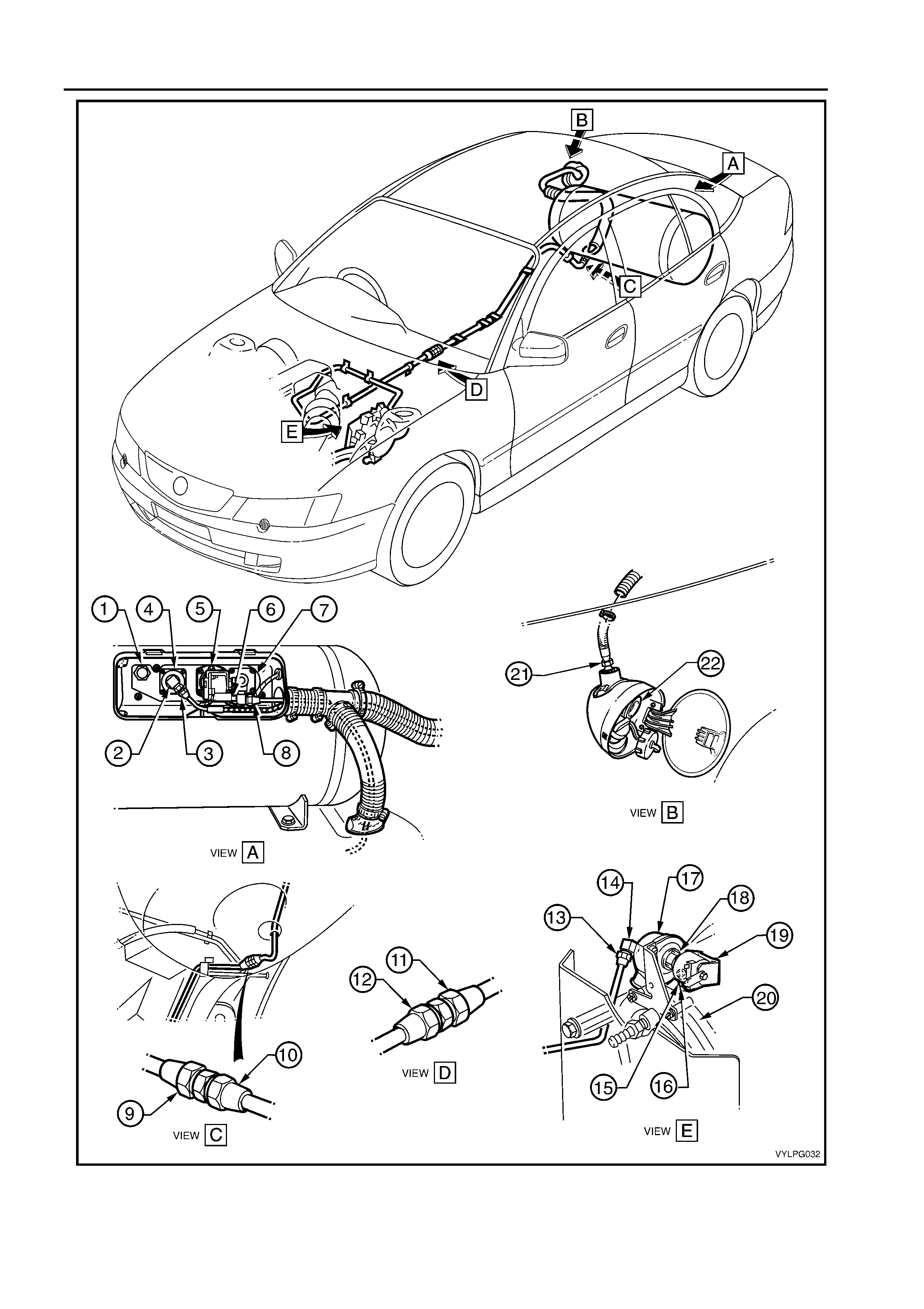
A. Refer to F igure 2-3, View A. Open rear compartment lid, remove
the valve box cover and leak test at and around the following:
- Pressure relief valve (1).
- AFL inlet elbow to AFL (2).
- Rear service line to AFL inlet elbow connection (3).
- AFL to LPG cylinder (4).
- Cylinder fuel gauge assembly (5).
- Solenoid and manual service valve assembly (6).
- Solenoid and manual service valve assembly to LPG
cylinder (7).
- Rear service line to solenoid and manual service valve
assembly connection (8).
B. Refer to F igure 2-3, View B.
Open filler box door and leak test at and around the filler valve
check ball (22).
Remove the quarter inner rear side carpet from the right side
wheelhouse to gain access to the inner side of the filler valve
assembly. For VY and VY2 Series vehicles, refer to Section 1A1
BODY in the MY 2003 VY and V2 Series Service Information.
For WK Series vehicles, refer to Section 1A8 HEADLINING AND
INTERIOR TRIM in the MY 2004 WK Series Service
information. Leak test at and around the filler line to filler valve
connection.
C. Refer to Figure 2-3, View C. From underneath the vehicle, leak
test at and around the following:
- Rear service line to intermediate service line joiner
connection (9).
- Intermediate service line to rear service line joiner
connection (10).
D. Refer to Figure 2-3, View D. From underneath the vehicle, leak
test at and around the following:
- Intermediate service line to front service line joiner
connection (11).
- Front service line to intermediate service line joiner
connection (12).
E. Refer to Figure 2-3, View E. Leak test in the engine
compartment, at and around the following:
- Front service line to lockoff inlet connection (13).
- Lockoff inlet connection to lockoff (14).
- Lockoff (17,18, 19)
- Lockoff to lockoff outlet connection (15).
- Lockoff outlet connection to converter (16).
- Converter mounting faces (20).
NOTE: The vehicle cannot be operated on LPG in the workshop, unless
the workshop is a 'Specialist Gas Workshop", refer Australian Standard
AS 2746 - 1985.
4. At the completion of the leak test, close the manual service valve,
start the engine and run the engine until all LPG in the service lines
is exhausted. With the engine stopped, switch to "petrol", and start
the engine.
5. The vehicle can now be driven into the workshop.
2-4 LPG LEAK TESTING
Figure 2-3
TECH 2 LPG SET-UP & ENABLE PROCEDURES 3-1
SECTION 3
CAUTION:
This vehicle is equipped with a Supplemental Restraint System (SRS). A SRS will consist of either driver’s and
front passenger’s airbags, or driver's and front passengers airbags an d front occupant seat belt pre-tensioners,
or driver’s and front passenger’s airbags an d front occupan t left and right hand sid e airbags and front occup ant
seat belt pre-tensioners. Refer to CAUTIONS in Section 12M of the MY 2003 VY and VY2 Series Service
Information before performing any service operation on or around SRS components, the steering mechanism or
wiring. Failure to follow the CAUTIONS could result in SRS deployment, resulting in possible personal injury or
unnecessary SRS system repairs.
TECH 2 LPG SET-UP & ENABLE PROCEDURES
CONTENTS
Ref. Subject Page
3.1 PCM SERVICE PROGRAMMING WITH LPG CALIBRATION................. 3-1
3.2 INSTRUMENT CLUSTER LPG LAMP ENABLE PROCEDURE.............. 3-4
3.3 PCM SET-UP PROCEDURE.................................................................... 3-6
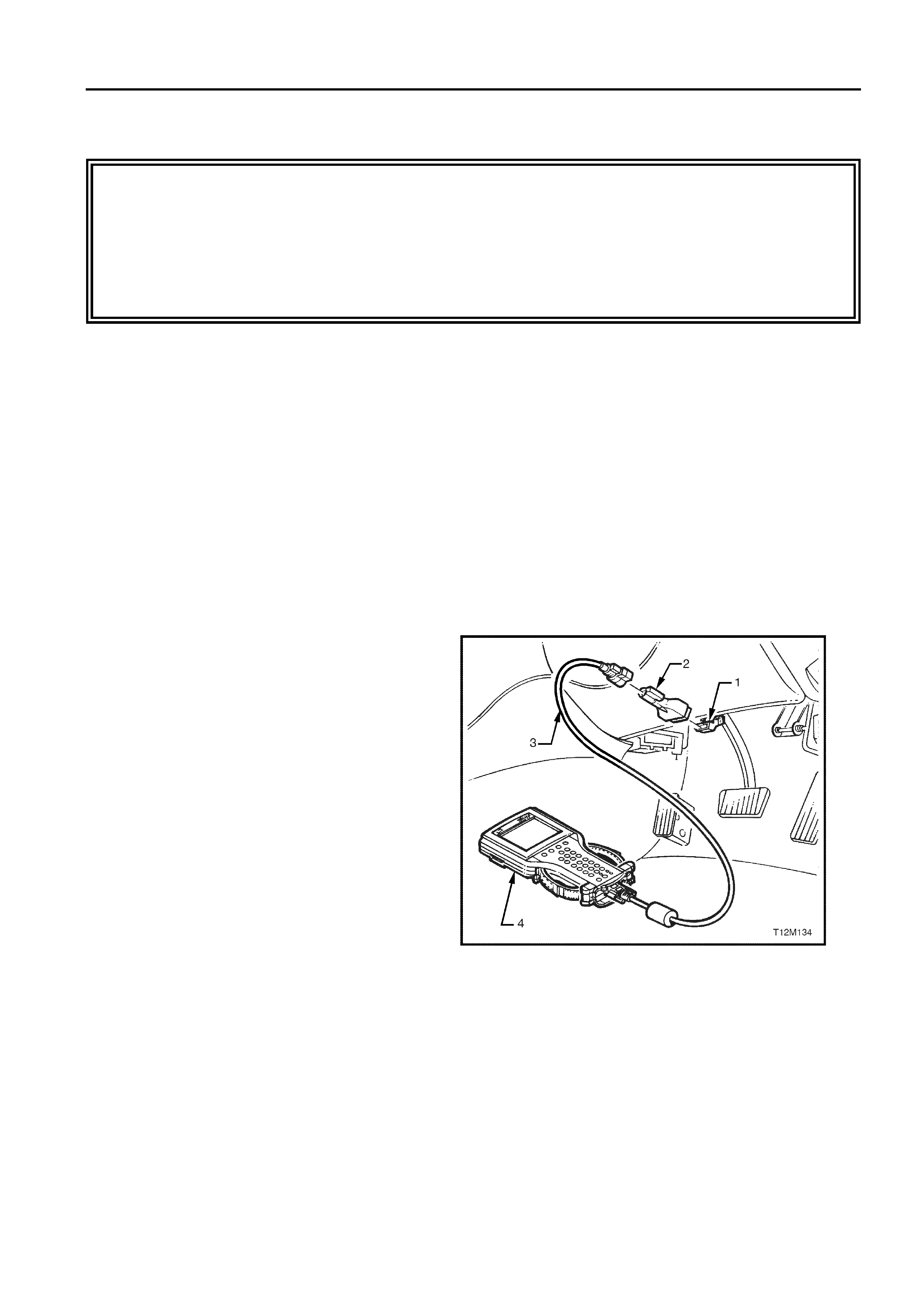
The following procedures are required to enable the
vehicle to operate on LPG and are best performed in the
order they they appear in this Section.
Prior to beginning, connect TECH 2 to the data link
connector (DLC).
1. DLC
2. DLC Adaptor
3. DLC Cable
4. TECH 2
Figure 3-1
3.1 PCM SERVICE PROGRAMMING
WITH LPG CALIBRATION
NOTE: T he following PCM service programming must be
performed following LPG system installation or when a
PCM has been replaced.
1. Connect Tech 2 as previously described.
2. Refer to the MY 2003 VY Series Service Information
and follow procedure 5.2 SPS PROCESS in Section
OC – TECH 2 until the Validate Vehicle Data screen
is displayed, refer Figure 3-2.
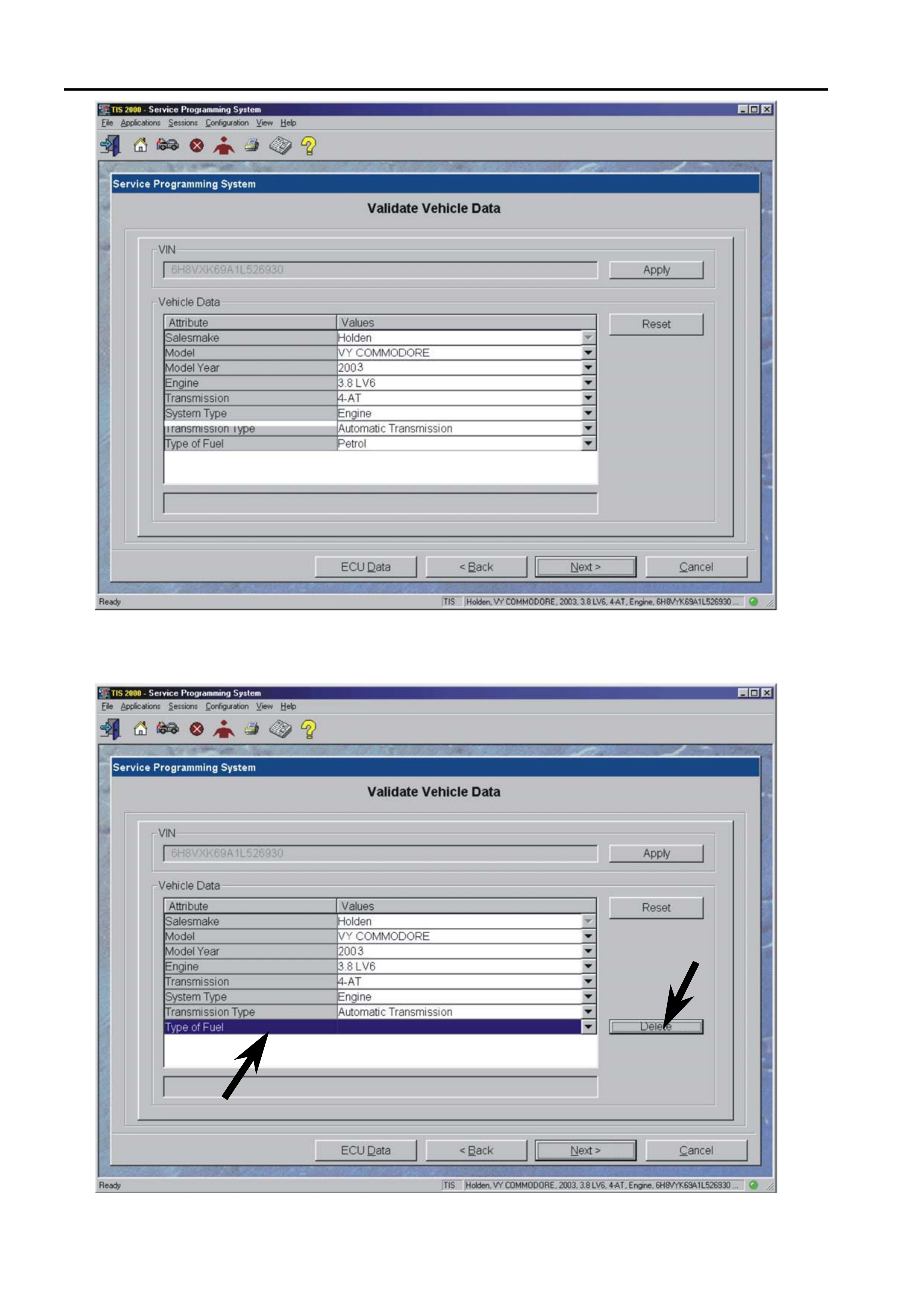
3-2 TECH 2 LPG SET-UP & ENABLE PROCEDURES
Figure 3-2
3. Select Type of Fuel (petrol), refer Figure 3-3.
4. Press the DELETE button.
Figure 3-3
5. Press the NEXT button, refer Figure 3-4.
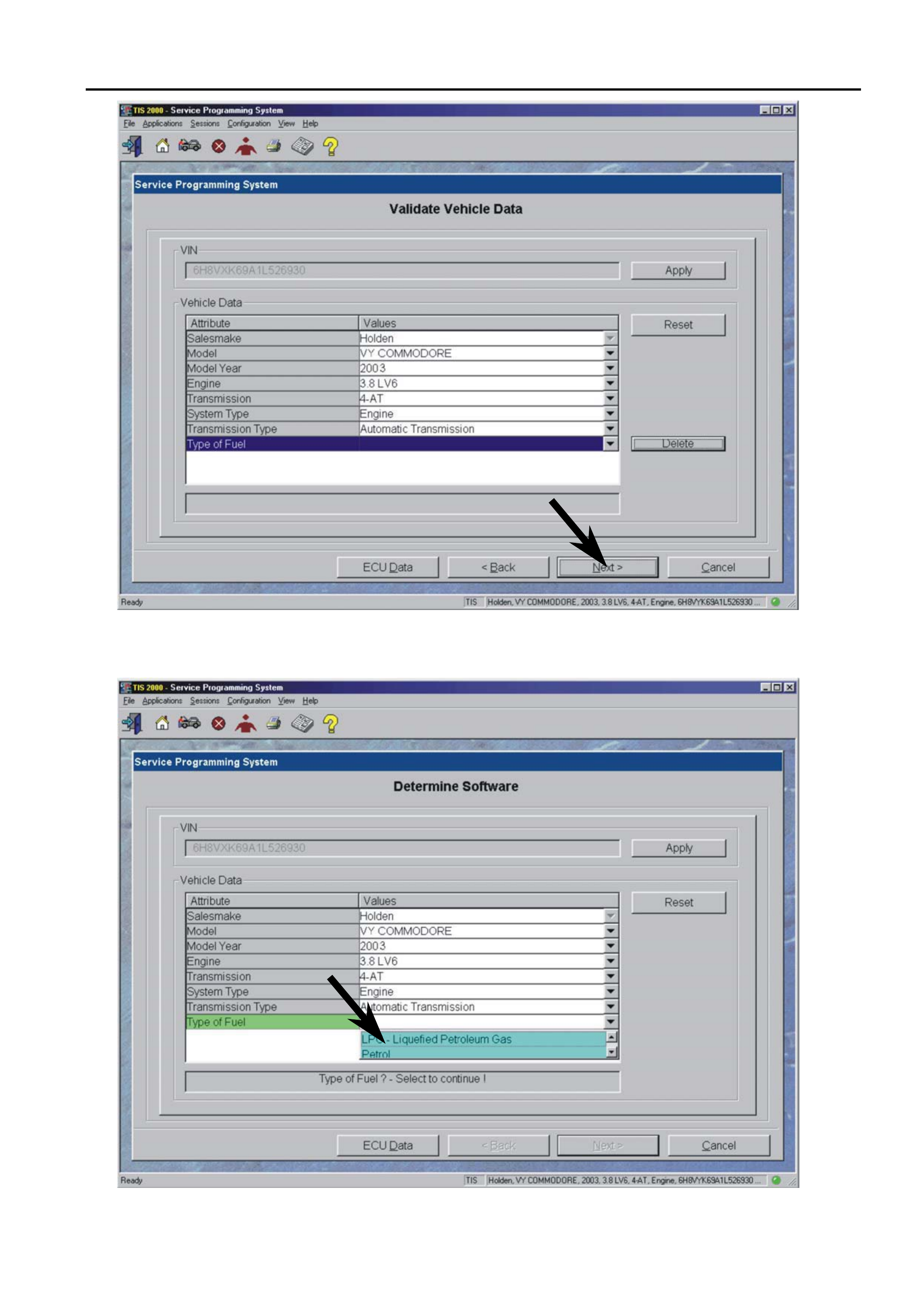
TECH 2 LPG SET-UP & ENABLE PROCEDURES 3-3
Figure 3-4
6. From the Type of Fuel drop-down list select LPG –
Liquefied Petroleum Gas, refer Figure 3-5.
Figure 3-5
3-4 TECH 2 LPG SET-UP & ENABLE PROCEDURES
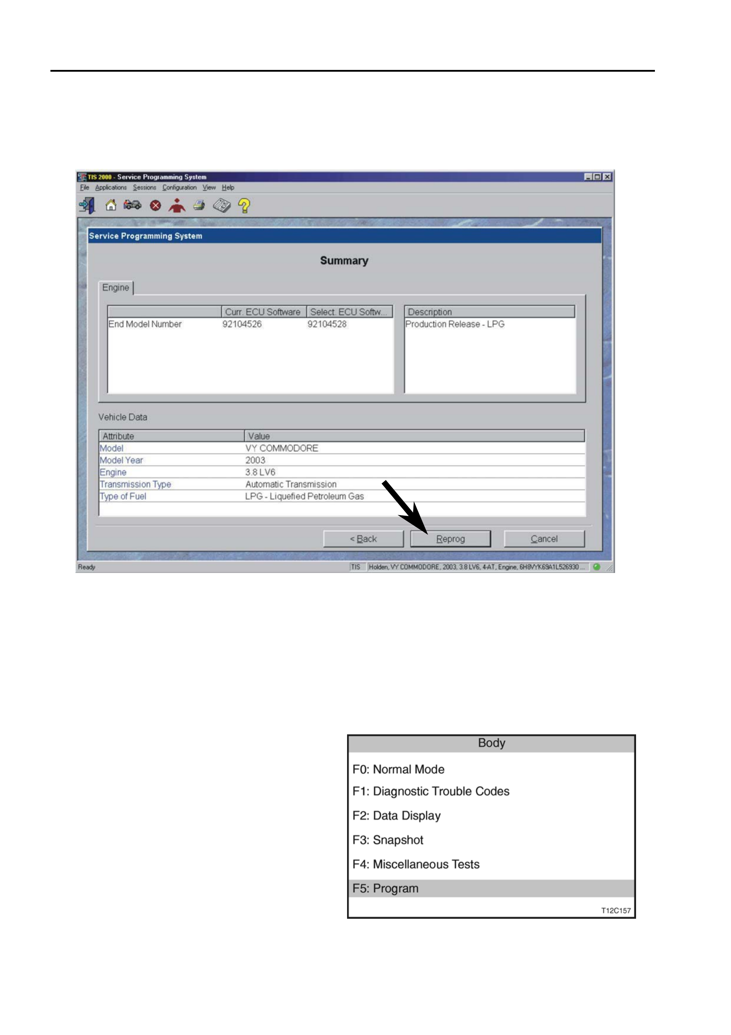
7. Once selected a summary screen will then be
displayed allowing the details to be confirmed, refer
to Figure 3-6.
8. Select the REPROG button.
9. Continue the steps in 5.2 SPS PROCESS procedure
on the Service Information.
Figure 3-6
3.2 INSTRUMENT CLUSTER LPG LAMP
ENABLE PROCEDURE
NOTE: The following instrument cluster LPG lamp
enable procedure must be performed following LPG
system installation or when an instrument cluster has
been replaced.
1. Ensure the ignition is off.
2. Connect Tech 2 as previously described.
3. Navigate through the Tech 2 menus to display the
Body / Instruments application menu.
4. Select F5: Program.
Figure 3-7
TECH 2 LPG SET-UP & ENABLE PROCEDURES 3-5
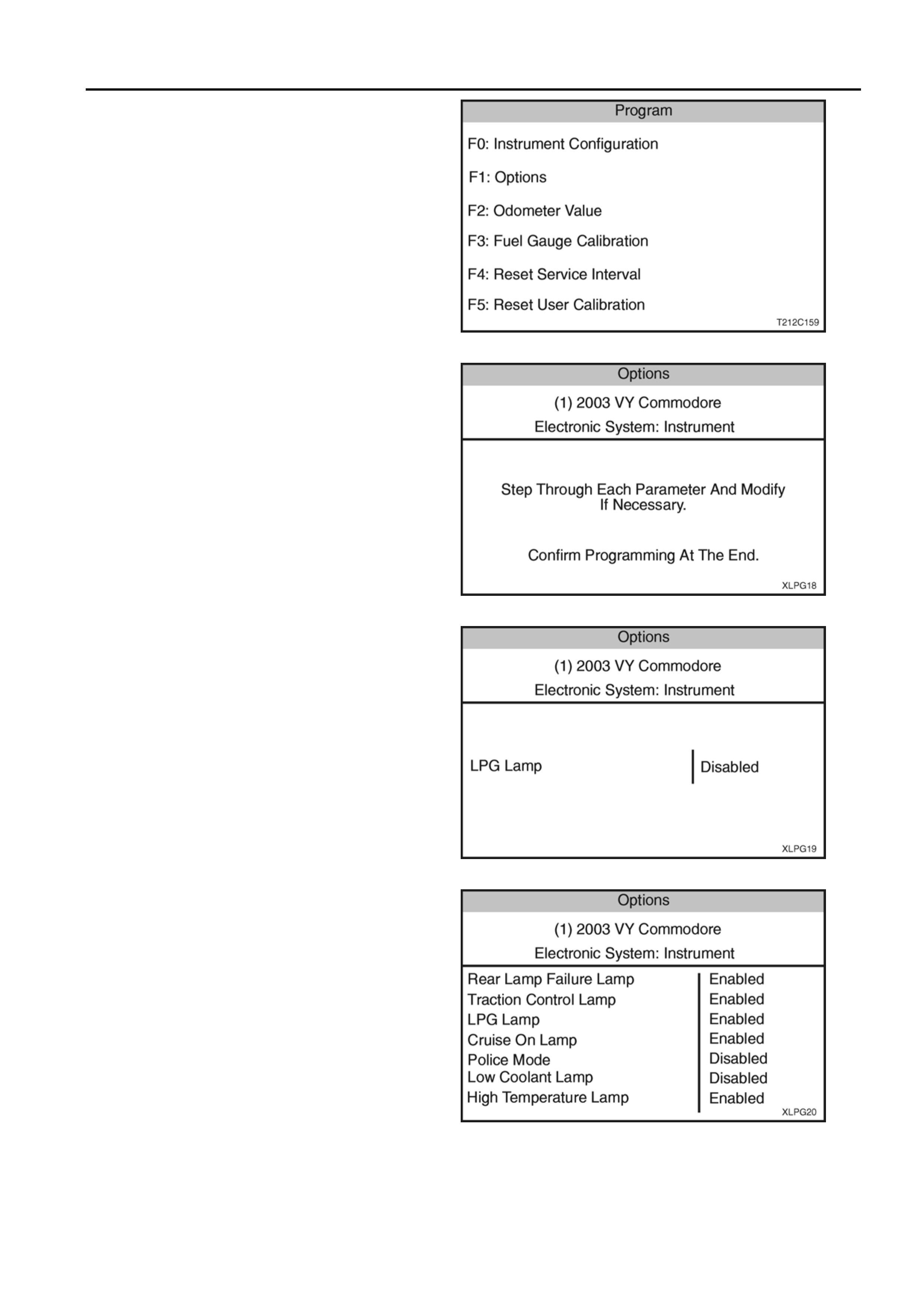
5. From the Program Menu, select F1: Options.
Figure 3-8
6. At the Options Menu, press the NEXT soft key and
scroll through the following series of screens to the
LPG Lamp screen:
- Rear Lamp Failure,
- Traction Control Off Lamp,
- LPG Lamp,
- Cruise On Lamp,
- Police Mode,
- Low Coolant Lamp,
- High Temperature Lamp,
- Program Options Confirm.
Figure 3-9
7. At the LPG Lamp screen, press the MODIFY soft
key to change Disabled to Enabled.
8. Use the NEXT key to scroll to the Program Options
Confirm screen.
Figure 3-10
9. At the Program Options Screen, ensure the LPG
Lamp is Enabled.
10. Press the ABORT soft key to abandon the process
or press the PROGRAM soft key to confirm the
parameters.
11. Press the CONFIRM soft key when the
programming is completed.
Figure 3-11
3-6 TECH 2 LPG SET-UP & ENABLE PROCEDURES
3.3 PCM SET-UP PROCEDURE
NOTE: The following LPG Set-up Procedure must be
performed following LPG system installation and when
any LPG system component (mixer, converter, FCV or
PCM) has been replaced, overhauled, reprogrammed, or
when the engine assembly has been replaced or
overhauled.
The LPG Set-up procedure allows adjustment of the idle
mixture under the following controlled conditions:
- Short and Long-Term Fuel Trim Cells set to zero.
- Fixed Spark advance.
- Fixed idle air control valve steps.
- Fuel control valve duty cycle fixed at 40%.
1. Connect TECH 2 as previously described.
2. Switch the vehicle to LPG mode, if not already done
so.
3. Start the engine and allow it and the oxygen sensors
to reach operating temperature, with no load on the
engine, air conditioning off (if fitted), all electrical
consumers turned off and park position selected.
4. On Tech 2 Select appropriate vehicle and details, for
example: Diagnostics / Appropriate Model Year ((1)
2003) / VY Commodore / Engine / V6 / Function
Tests/ LPG Set-up.
During the set-up procedure, Tech 2 ensures the
follow engine operating conditions are met and
maintained:
- Engine Coolant Temperature greater than 91°C
- Operating in closed loop.
- Right hand oxygen sensor is ready.
- The engine cooling fan is off (engine coolant
temperature less than 104°C).
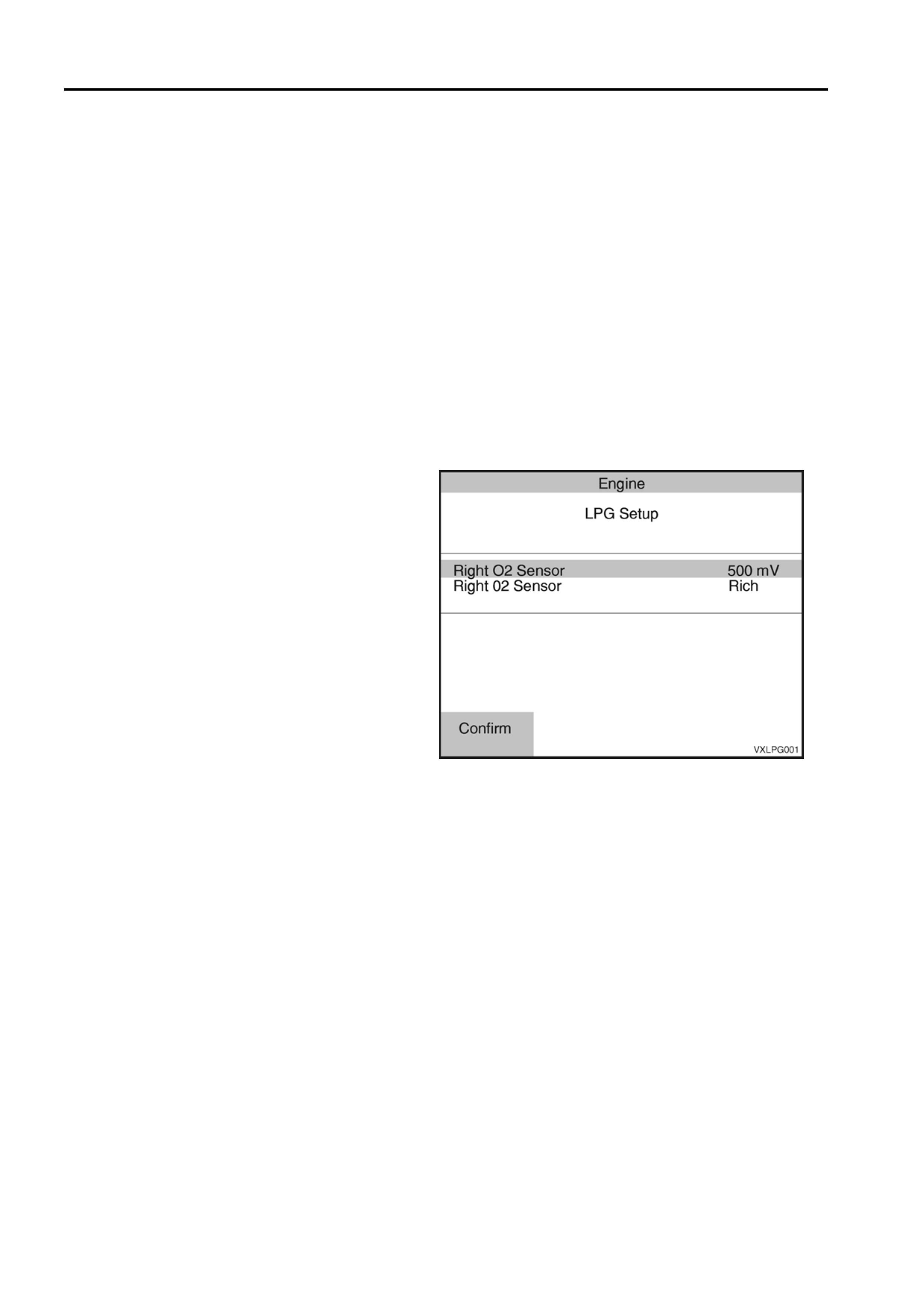
Once all the preconditions have been met, Tech 2
will display the Right O2 Sensor Voltage and Status.
Figure 3-12
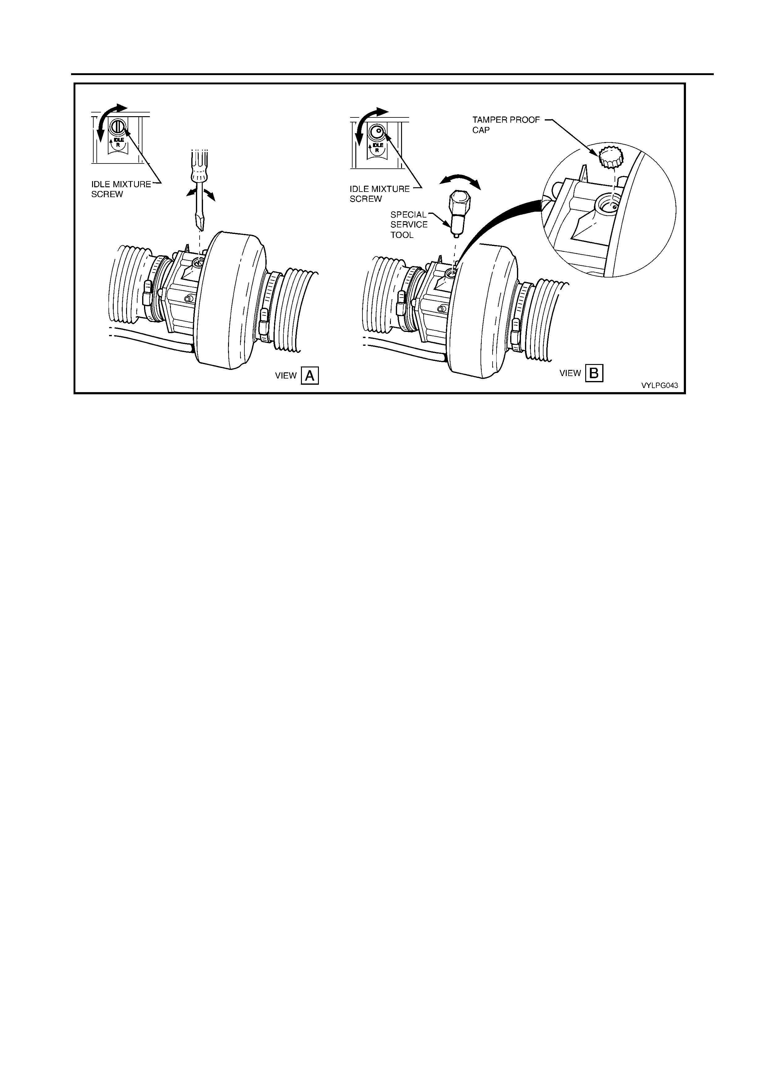
5. Adjust the idle mixture screw until the right hand
oxygen sensor voltage is as close to 500 mV as
possible and the status of the right O2 Sensor is
constantly toggling between rich and lean. For VY
vehicles and VY2 vehicles built prior to 2004, use a
flat blade screwdriver, refer to Figure 3-13, View A,
for VY2 vehicles built in or after January 2004, and
WK vehicles, use the special service tool with an
open-ended spanner or adjustable wrench to turn,
refer to Figure 3-13, View B.
Oxygen sensor voltages greater than 500 mV
indicates a rich mixture, turn the idle mixture screw
anti-clockwise to lean off the mixture.
Oxygen sensor voltages less than 500 mV indicates
a lean mixture, turn the idle mixture screw clockwise
to enrich the mixture.
If the engine coolant temperature exceeds 104°C,
the engine cooling fan will be turned on and Tech 2
will suspend the set-up procedure. When the engine
cools down and the cooling fan is turned off, T ech 2
will continue with the set-up procedure.
TECH 2 LPG SET-UP & ENABLE PROCEDURES 3-7
Figure 3-13
6. For VY2 vehicles built in or after January 2004
(those fitted with Euro 2 compliant exhaust system
with close coupled catalytic converters) and WK
vehicles, install the tamper proof cap supplied with
the LPG kit over the idle mixture screw and tap
down into place.


LPG AFTER INSTALLATION CHECK 4-1
SECTION 4
CAUTION:
This vehicle is equipped with a Supplemental Restraint System (SRS). A SRS will consist of either driver’s and
front passenger’s airbags, or driver's and front passengers airbags an d front occupant seat belt pre-tensioners,
or driver’s and front passenger’s airbags an d front occupan t left and right hand sid e airbags and front occup ant
seat belt pre-tensioners. Refer to CAUTIONS in Section 12M of the MY 2003 VY and VY2 Series Service
Information before performing any service operation on or around SRS components, the steering mechanism or
wiring. Failure to follow the CAUTIONS could result in SRS deployment, resulting in possible personal injury or
unnecessary SRS system repairs.
LPG AFTER INSTALLATION CHECK
CONTENTS
Ref. Subject Page Ref. Subject Page
4.1 GENERAL INFORMATION ............................... 4-1
4.2 UNDERBODY.................................................... 4-2
4.3 REAR COMPARTMENT.................................... 4-3
4.4 VEHICLE INTERIOR......................................... 4-4
4.5 UNDER BONNET..............................................4-5
4.6 LEAK CHECK AND FILLING ............................4-6
4.7 FILLING .............................................................4-7
4.8 COMMISSIONING OF VEHICLE.......................4-7
4.1 GENERAL INFORMATION
On completion of the LPG installation, it is a requirement of
HOLDEN Ltd (A.C.N. 006 893 232) that the copy of the
following check list, supplied in the LPG Kit, must be
completed and filed by the fitting dealer to ensure a high
quality installation standard. Be advised that HOLDEN Ltd
reserves the right at any time to audit any after installation
check sheet.
All items in this checklist must be checked to ensure they have been installed, adjusted or reinstalled as outlined in the
Installation Instructions, or applicable Service Information.
DATE:................................................... VEHICLE:..................................................................................................
VIN No. REGISTRATION No. ..................................................... REGISTRATION No..........................................
Kit No............................................................................................................................................................................
AUTHORISED DEALER:............................................................. LICENCE No:.....................................................
FITTER:....................................................................................... LICENCE No:.....................................................

4-2 LPG AFTER INSTALLATION CHECK
4.2 UNDERBODY
(Tick the appropriate box)
CHECK OK REPAIR
1. Rear service line and intermediate service line
connected to joiner (near grommet in rear longitudinal)
and connectors tightened to correct torque specification.
2. Front and intermediate service lines connected to joiner
just forward of brake/fuel pipe harness cover and
connectors tightened to correct torque specification.
3. Front and intermediate service lines are not chafing or in
contact with the brake, petrol or evaporative lines, body,
or any other components.
4. Front and intermediate service lines correctly routed and
retaining clips installed.
5. LPG cylinder correctly installed and attaching nuts
tightened to correct torque specifications (4 locations).
6. Rear springs installed and rear shock absorber
mounting bolts tightened to correct torque
specifications.

LPG AFTER INSTALLATION CHECK 4-3
4.3 REAR COMPARTMENT
(Tick the appropriate box)
CHECK OK REPAIR
1 Floor flange installed and silicone sealer applied.
2 Service line vent tube installed to floor flange and
retaining clamps tightened.
3 Service line vent tube installed, joiner and retaining
clamp tightened.
4 Filler connected to joiner and LPG cylinder high-
pressure inlet elbow and filler line connectors tightened
to the correct torque specification.
5 Filler plate installed correctly and retaining cap screws
tightened to the correct torque specifications.
6 Filler lid operates without binding and shuts flush, AFL
label is affixed to inside of filler lid.
7 Rear service line connected to solenoid and manual
service valve assembly and connector tightened to the
correct torque specification.
8 LPG cylinder level sender and smart unit harness
connector is connected to LPG body harness connector.
9 LPG body harness is correctly routed and retained to
existing harness with cable ties (five places).
10 Emergency decklid release cable extension has been
installed and operates correctly.
11 Rear compartment carpet and quarter trim carpet have
been reinstalled and are positioned correctly.
4-4 LPG AFTER INSTALLATION CHECK
4.4 VEHICLE INTERIOR
(Tick the appropriate box)
CHECK OK REPAIR
1. All of the following LPG body harness connections are
installed:
a. LPG body harness fuel mode switch connector to
fuel mode switch.
b. LPG body harness single lead PCM terminals are
correctly inserted to PCM connectors.
c. LPG body harness flying leads to the main wiring
harness to body wiring harness connector and the
3-pin female patch connector respectively. Also,
the body wiring harness lead connected to male
3
-
pin connector
2. Rear seat and RHR seat back reinstalled.
3. RHF instrument panel lower trim assembly and floor
console and floor console cover reinstalled with auxiliary
it h t d t th i
ti h
4. LPG harness routing not impairing heater valve.
O
p
erate the heater controls to ensure that the harness
5. PCM connectors are installed correctly.
6. LH & RH lower side trim assemblies and rocker panel
cover installed.
7. All instrument panel controls function correctly.

LPG AFTER INSTALLATION CHECK 4-5
4.5 UNDER BONNET
(Tick the appropriate box)
CHECK OK REPAIR
1. All the following LPG engine harness connections are
installed and routed correctly:
a. Earth lead is installed to rear of LH cylinder head
and retaining bolt is tightened to the correct torque.
b. LPG engine harness lockoff connector is connected
to LPG lockoff.
c. LPG engine harness fuel control valve connectors
connected to fuel control valve.
2. The vapour line to mixer and vapour line to converter
retaining clamps are installed and tightened.
3. The vapour line and vacuum hoses are connected and
routed correctly.
4. Converter and converter bracket installed and retaining
bolts are tightened to the correct torque specification.
5. Coolant pipe hose clamps fitted and tightened. Coolant
and vapour hoses correctly routed to avoid contact with
engine or body parts.
6. Fuel control valve (FCV) installed.
7. Air intake tube installed, clamps and mounting screw
tightened to the correct torque specification.
8. Air cleaner assembly and MAF sensor installed.
9. Front service line 'P' clam ps installed on cockpit module
and tightened to the correct torque specification.

4-6 LPG AFTER INSTALLATION CHECK
4.6 LEAK CHECK AND FILLING
With approximately three litres of LPG in the cylinder, leak
test the complete LPG system as outlined in the leak test
procedure in Section 2 of the installation instructions. The
following 19 points must have been tested.
(Tick the appropriate box)
CHECK OK REPAIR
1. Pressure relief valve.
2. Solenoid and manual service valve assembly to LPG
cylinder.
3. Solenoid and manual service valve assembly.
4. Rear service line to solenoid and manual service valve
assembly connector.
5. LPG cylinder fuel gauge assembly.
6. AFL inlet elbow to LPG cylinder.
7. Rear service line to AFL inlet elbow connector.
8. AFL to LPG cylinder.
9. Filler valve to filler line.
10. Filler valve check ball.
11. Rear service line to intermediate service line joiner
connection.
12. Intermediate service line to rear service line joiner
connection.
13. Intermediate service line to front service line joiner
connection.
14. Front service line to intermediate service line joiner
connection.
15. Front service line to LPG lockoff inlet straight nipple
connection.
16. LPG lockoff inlet connection to LPG lockoff.
17. LPG lockoff.
18. LPG lockoff to LPG lockoff outlet connection.
19. LPG lockoff outlet connection to converter.

LPG AFTER INSTALLATION CHECK 4-7
4.7 FILLING
After the leak test has been completed and there are NO
LEAKS, fill the LPG cylinder and record the number of litres
taken.
NOTE: Don’t forget the three litres you put into the LPG
cylinder to conduct the Leak Test.
The LPG cylinder capacity of 74 litres is the 'fillable' capacity.
Automatic Fill Limiter (AFL) operation.
Total Litres Taken.
______________________________ Litres
4.8 COMMISSIONING OF VEHICLE
(Tick the appropriate box)
CHECK OK REPAIR
1. Glove box installed, key and lock operate correctly.
2. PCM has been reprogrammed with LPG calibration.
3. LPG idle mixture has been set according to the PCM
Set-up procedure.
4. Vehicle’s fuel changeover operation.
5. Registration plate LPG mounting brackets & labels
affixed.
6. LPG compliance plate affixed.
7. LPG installation Build Plate affixed.
8. Windscreen label affixed.
9. LPG Tank Important Notice label affixed
10. Tyre Placard label affixed
11. Owner Handbook LPG Supplement provided in
glove box.
12. Road test vehicle.
13. Warranty card filled out.

4-8 LPG AFTER INSTALLATION CHECK
NOTES
_________________________________________________________________________________________________
_________________________________________________________________________________________________
_________________________________________________________________________________________________
_________________________________________________________________________________________________
_________________________________________________________________________________________________
_________________________________________________________________________________________________
_________________________________________________________________________________________________
_________________________________________________________________________________________________
_________________________________________________________________________________________________
_________________________________________________________________________________________________
_________________________________________________________________________________________________
_________________________________________________________________________________________________
_________________________________________________________________________________________________
_________________________________________________________________________________________________
_________________________________________________________________________________________________
_________________________________________________________________________________________________
_________________________________________________________________________________________________
_________________________________________________________________________________________________
_________________________________________________________________________________________________
_________________________________________________________________________________________________
_________________________________________________________________________________________________
_________________________________________________________________________________________________
_________________________________________________________________________________________________
_________________________________________________________________________________________________
_________________________________________________________________________________________________
_________________________________________________________________________________________________
_________________________________________________________________________________________________
_________________________________________________________________________________________________
_________________________________________________________________________________________________
_________________________________________________________________________________________________
_________________________________________________________________________________________________
_________________________________________________________________________________________________
_________________________________________________________________________________________________
_________________________________________________________________________________________________
_________________________________________________________________________________________________
_________________________________________________________________________________________________
_________________________________________________________________________________________________
_________________________________________________________________________________________________
_________________________________________________________________________________________________
_________________________________________________________________________________________________
_________________________________________________________________________________________________
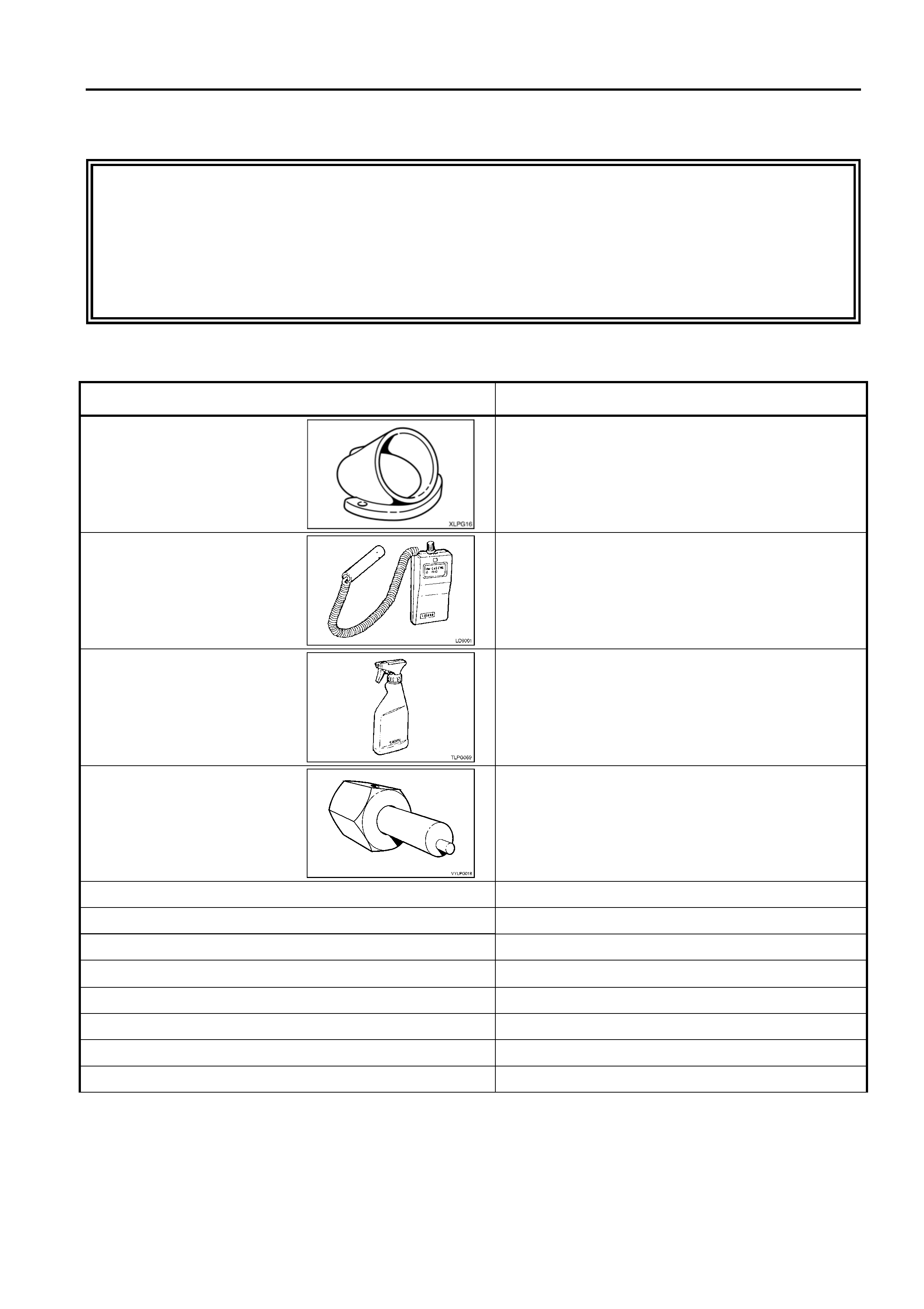
LPG INSTALLATION TOOLS 5-1
SECTION 5
CAUTION:
This vehicle is equipped with a Supplemental Restraint System (SRS). A SRS will consist of either driver’s and
front passenger’s airbags, or driver's and front passengers airbags an d front occupant seat belt pre-tensioners,
or driver’s and front passenger’s airbags an d front occupan t left and right hand sid e airbags and front occup ant
seat belt pre-tensioners. Refer to CAUTIONS in Section 12M of the MY 2003 VY and VY2 Series Service
Information before performing any service operation on or around SRS components, the steering mechanism or
wiring. Failure to follow the CAUTIONS could result in SRS deployment, resulting in possible personal injury or
unnecessary SRS system repairs.
LPG INSTALLATION TOOLS
TOOL PURPOSE
Drilling Jig
Used for drilling floor flange hole in rear floor panel
Leak Tester:
Combustible-gas detector
LD-9001 or equivalent
LPG system leak testing
Spray bottle & foaming agent.
Gameco Leakcheck™ or
equivalent
Idle air screw adjustment tool.
Used to adjust idle screw on LPG mixer assembly during
PCM setup procedure (Euro 2 VY2 and WK vehicles
only).
LPG cylinder location drilling jig LPG cylinder
Converter support bracket drilling jig Converter support bracket
Rivet gun Self closing pop rivets
10mm right angle (90°) drill Drilling holes
Hole saws: 60mm Vent hose flange and fuel filler
51mm Fuel filler
30mm Dash panel
21mm Fuel filler

5-2 LPG AFTER INSTALLATION CHECK
Drill bits: 11.0mm LPG cylinder
6.5mm & 9.0mm LPG converter
5.0mm Rivets
4.2mm (short) Vent hose flange / compliance plate
3.5mm Fuel filler locating pin
3.0mm Pilot holes / registration plate label mounting plate
3mm letter punch & number punch sets Compliance Plate
Loctite 577 sealant Gas tight connection threads
Anti-corrosion compound meeting Holden Specification HN1071 Bare metal surfaces
Silicone sealer meeting Holden Specification HN1886 Floor flange

LPG INSTALLATION TOOLS 5-3
NOTES
__________________________________________________________________________________________________
__________________________________________________________________________________________________
__________________________________________________________________________________________________
__________________________________________________________________________________________________
__________________________________________________________________________________________________
__________________________________________________________________________________________________
__________________________________________________________________________________________________
__________________________________________________________________________________________________
__________________________________________________________________________________________________
__________________________________________________________________________________________________
__________________________________________________________________________________________________
__________________________________________________________________________________________________
__________________________________________________________________________________________________
__________________________________________________________________________________________________
__________________________________________________________________________________________________
__________________________________________________________________________________________________
__________________________________________________________________________________________________
__________________________________________________________________________________________________
__________________________________________________________________________________________________
__________________________________________________________________________________________________
__________________________________________________________________________________________________
__________________________________________________________________________________________________
__________________________________________________________________________________________________
__________________________________________________________________________________________________
__________________________________________________________________________________________________
__________________________________________________________________________________________________
__________________________________________________________________________________________________
__________________________________________________________________________________________________
__________________________________________________________________________________________________
__________________________________________________________________________________________________
__________________________________________________________________________________________________
__________________________________________________________________________________________________
__________________________________________________________________________________________________
__________________________________________________________________________________________________
__________________________________________________________________________________________________
__________________________________________________________________________________________________
__________________________________________________________________________________________________
__________________________________________________________________________________________________
__________________________________________________________________________________________________
__________________________________________________________________________________________________
__________________________________________________________________________________________________
__________________________________________________________________________________________________


PARTS LIST 6-1
SECTION 6
CAUTION:
This vehicle is equipped with a Supplemental Restraint System (SRS). A SRS will consist of either driver’s and
front passenger’s airbags, or driver's and front passengers airbags an d front occupant seat belt pre-tensioners,
or driver’s and front passenger’s airbags an d front occupan t left and right hand sid e airbags and front occup ant
seat belt pre-tensioners. Refer to CAUTIONS in Section 12M of the MY 2003 VY and VY2 Series Service
Information before performing any service operation on or around SRS components, the steering mechanism or
wiring. Failure to follow the CAUTIONS could result in SRS deployment, resulting in possible personal injury or
unnecessary SRS system repairs.
PARTS LIST - VY
PART NO DESCRIPTION QTY PART NO DESCRIPTION QTY
92060732 BOLT/SCREW-LPG VAPORIZER HTR
HOSE CLAMP 14 92138003 CLAMP, VALVE BOX/VENT PIPE 4
92052506 DUCT ASM-AIR METER TO MIXER 1 92138061 CLAMP-FILLER HOSE VENT TUBE 2
92055702 INDUCTION TUBE 1 92138551 SCREW-POCKET FLANGE (M6x2) 2
92052498 CLAMP-INDUCTION TUBE-MIXER TO 3 92138212 STRAP 14
92100188 BRACKET-CONVERTOR MOUNT-L 1 92076450 CONVOLUTED TUBE-H/T LEAD 3
92087758 NUTSERT-M6x1 1 92119976 SUPPLEMENT, OWNERS SERVCE 1
09440004 NUT-CONV BRKT TO BODY 5 92077227 CAP-FUEL FILLER 1
92078978 SLEEVE, HEAT 1 92141575 CLAMP 1
92081623 HEAT SHIELD-CONVERTER 1 92055731 REMOTE FILLER ASM-LPG CYL 1
92056796 SUPPORT-HEAT SHIELD-FRONT 1 92055733 HOSE ASM-LPG CYL FILLER 1
92056797 SUPPORT-HEAT SHIELD-REAR 1 92055736 VENT TUBE-LPG CYL TO JOINER 1
92088197 VAPOUR HOSE-CONVERTER TO MIXER 1 92058201 POCKET FLANGE, FUEL 1
92094519 CLAMP - HOSE 25-38MM 3 92145288 PIPE, REAR ASSEMBLY 1
92055705 HOSE-HTR WATER VALVE TO
CONVERTER 1 92145289 PIPE, MID ASSEMBLY 1
92055706 HOSE-CONV. TO ENGINE WATER INLET 1 92145290 PIPE, FRONT ASSEMBLY 1
92138004 CLAMP-HOSE TO CONVERTER 3 92049210 AIR CLEANER, UPPER 1
92055707 CLAMP-HOSE TO BODY 4 11084962 SCREW, FLANGE 4
92138020 SCREW 1 92049008 ADAPTOR, AIR CLEANER 1
92055708 CONVOLUTED TUBE-HOSE PROTECTOR 7 92023739 ADAPTOR, AFM 1
92057573 GROMMET-THROTTLE BODY 1 92032690 GASKET, AIR CLEANER 1
92057558 HOSE, CRANKCASE VENT 1 92053006 HOUSING, AIR CLEANER BOTTOM 1
92083934 HOSE-CONV. TO PURGE VALVE 1 92058202 WASHER, FILLER VALVE 1
92083935 HOSE-MIXER TO PURGE VALVE 1 92058203 NUT, FILLER VALVE 1
92083936 HOSE-CONV. TO MIXER BALANCER 1 92055737 VENT TUBE, LPG FILLER TO JOINER 1
92083937 VAPOUR HOSE INSULATOR 1 92056801 JOINER, VENT TUBE 1
92083938 MIXER ASM-COMPLETE 1 92041796 ELEMENT ASM - A/CL 1
92083939 CONVERTER ASM-COMPLETE 1 92056798 BRACKET ASM -A/CL 1
1997278 VALVE ASM-PURGE 1 11063471 NUT - A/CL 3
92055714 HEAT SHIELD-LPG SUPPLY PIPE 1 09281374 INSULATOR ASM-A/CL 3
92138381 RIVET 25 92056550 DUCT, FRONT INLET AIR 1
92055723 LABEL-LPG 4 92053315 DUCT ASM - RR INLET AIR 1
92055724 LABEL-LPG INSTRUCTION 1 92076145 HOSE - INLET AIR MASS METER 1
92091859 REGO LABEL ASM-LPG 2 92120937 LABEL TYRE PRESSURE 1
92055725 TANK ASSEMBLY-LPG SEDAN 1 92113477 SWITCH, LPG 1
92055726 BRACKET-LPG CYLINDER ATTACH-RH 1 92111640 ESCUTCHEON 1
92055727 BRACKET-CYLINDER ATTACH-LH 1 92111636 SWITCH, BLANK 3
11090684 SCREW: M8 x 1.25 x 25 8 92159343 HARNESS, LPG PATCH 1
92055728 REINF.-LPG CYL ATTACH RHS 1 92055741 SPRINGS - RR 2
92055729 REINF.-LPG CYL ATTACH-LHS 1 92057566 CLAMP, LPG SUPPLY 2
92138241 SCREW, REINF. TO LPG TANK 2 92092925 LABEL, TRAC W ARNING 1
11095803 NUT-CONELOCK-REINF. TO LPG 2 92141576 CLAMP, HOSE 9MM 9
11086952 NUT-8MM 1 92103564 STRAP-R/CMPT LID LATCH RELEASE
CABLE 1
92058200 GROMMET - VENT HOSE 1 92159346 CARD, WARRANTY 1
92057565 FITTING-5/16 SAE STRAIGHT 2 92159345 INSTRUCTIONS, FITTING 1
92055738 FLOOR FLANGE-VENT TUBE ATTACH 1 92159344 PLATE, LPG ID 1
92055739 VENT TUBE-JOIN TO FLOOR FLANGE 1

6-2 PARTS LIST
PARTS LIST - VY2 (Build January 2004 onwards)
NOTE: For VY2 series vehicles built in or after January 2004, a unique Euro 2 configured mixer assembly with tamper proof
idle mixture screw and cap is used. This mixer is the same as that used on Euro 2 configured WK LPG systems.
VY2 V6 vehicles built from the start of 2004 can be identified by their exhaust system, which incorporates two close-coupled
catalytic converters, mounted along the front exhaust assembly pipes close to the manifold flange joints.
For VY2 V6 vehicles built before 2004, the mixer assembly supplied with the LPG installation kit is identical to that used on
VY V6 vehicles. The exhaust system on these vehicles incorporates a single catalytic converter, mounted along the front
pipes close to the intermediate to front pipe flange.
PART NO DESCRIPTION QTY PART NO DESCRIPTION QTY
92060732 BOLT/SCREW-LPG VAPORIZER HEATER
HOSE CLAMP 14 92055739 VENT TUBE-JOIN TO FLOOR FLANGE 1
92052506 DUCT ASM-AIR METER TO MIXER 1 92138003 CLAMP, VALVE BOX/VENT PIPE 4
92055702 INDUCTION TUBE 1 92138061 CLAMP-FILLER HOSE VENT TUBE 2
92052498 CLAMP-INDUCTION TUBE-MIXER TO 3 92138551 SCREW-POCKET FLANGE (M6x2) 2
92100188 BRACKET-CONVERTOR MOUNT 1 92138212 STRAP 14
92087758 NUTSERT-M6x1 1 92076450 CONVOLUTED TUBE-H/T LEAD 3
09440004 NUT-CONVERTER BRACKET TO BODY 5 92119976 SUPPLEMENT, OW NERS SERVICE 1
92078978 SLEEVE, HEAT 1 92077227 CAP-FUEL FILLER 1
92081623 HEAT SHIELD-CONVERTER 1 92141575 CLAMP 1
92056796 SUPPORT-HEAT SHIELD-FRONT 1 92055731 REMOTE FILLER ASM-LPG CYL 1
92056797 SUPPORT-HEAT SHIELD-REAR 1 92055733 HOSE ASM-LPG CYL FILLER 1
92088197 VAPOUR HOSE-CONVERTER TO MIXER 1 92055736 VENT TUBE-LPG CYL TO JOIN 1
92094519 CLAMP - HOSE 25-38MM 3 92058201 POCKET FLANGE, FUEL 1
92055705 HOSE-HEATER WATER VALVE TO
CONVERTER 1 92145288 PIPE, REAR ASSEMBLY 1
92055706 HOSE-CONVERTER TO ENG. W ATER
INLET 1 92145289 PIPE, MID ASSEMBLY 1
92138004 CLAMP-HOSE TO CONVERTER 3 92145290 PIPE, FRONT ASSEMBLY 1
92055707 CLAMP-HOSE TO BODY 4 92049210 AIR CLEANER, UPPER 1
92138020 SCREW 1 11084962 SCREW, FLANGE 4
92055708 CONVOLUTED TUBE-HOSE PROTECTOR 7 92049008 ADAPTOR, AIR CLEANER 1
92057573 GROMMET-THROTTLE BODY 1 92023739 ADAPTOR, AFM 1
92057558 HOSE, CRANKCASE VENT 1 92032690 GASKET, AIR CLEANER 1
92083934 HOSE-CONV. TO PURGE VALVE 1 92053006 HOUSING, AIR CLEANER BOTTOM 1
92083935 HOSE-MIXER TO PURGE VALVE 1 92058202 WASHER, FILLER VALVE 1
92083936 HOSE-CONV. TO MIXER BALAN 1 92058203 NUT, FILLER VALVE 1
92083937 VAPOUR HOSE INSULATOR 1 92055737 VENT TUBE, LPG FILLER TO JOINER 1
92083938 For VY2 Built before Jan 2004:
MIXER ASM-COMPLETE 1 92056801 JOINER, VENT TUBE 1
92165980 For VY2 Built Jan 2004 and onwards:
MIXER ASM-COMPLETE
(Euro 2 tamper proof)
1 92041796 ELEMENT ASM - A/CL 1
92165981 For VY2 Built Jan 2004 and onwards:
CAP-CARB IDLE MIX NEEDLE
(With tamper proof mixer idle adjust cap)
1 92056798 BRACKET ASM -A/CL 1
92083939 CONVERTER ASM-COMPLETE 1 11063471 NUT - A/CL 3
1997278 VALVE ASM-PURGE 1 09281374 INSULATOR ASM-A/CL 3
92055714 HEAT SHIELD-LPG SUPPLY PIPE 1 92056550 DUCT, FRT INT AIR 1
92138381 RIVET 25 92053315 DUCT ASM - RR INLET AIR 1
92055723 LABEL-LPG 4 92076145 HOSE - INLET AIR MASS METER 1
92055724 LABEL-LPG INSTRUCTION 1 92120937 LABEL TYRE PRESSURE 1
92091859 REGO LABEL ASM-LPG 2 92113477 SWITCH, LPG 1
92055725 TANK ASSEMBLY-LPG SEDAN 1 92111640 ESCUTCHEON 1
92055726 BRACKET-LPG CYLINDER ATTACH-RH 1 92111636 SWITCH, BLANK 3
92055727 BRACKET-LPG CYLINDER ATTACH-LH 1 92159343 HARNESS, LPG PATCH 1
11090684 SCREW: M8 x 1.25 x 25 8 92055741 SPRINGS - RR 2
92055728 REINF-LPG CYL ATTACH RHS 1 92057566 CLAMP, LPG SUPPLY 2
92055729 REINF-LPG CYL ATTACH-LHS 1 92092925 LABEL, TRAC WARNING 1
92138241 SCREW, REINF TO LPG TANK 2 92141576 CLAMP, HOSE 9MM 9
11095803 NUT-CONELOCK-REINFORCEMENT TO
LPG 2 92103564 STRAP-R/CMPT LID LATCH RELEASE
CABLE 1
11086952 NUT-8MM 1 92159346 CARD, WARRANTY 1
92058200 GROMMET - VENT HOSE 1 92159345 INSTRUCTIONS, FITTING 1
92057565 FITTING-5/16 SAE STRAIGHT 2 92159344 PLATE, LPG ID 1
92055738 FLOOR FLANGE-VENT TUBE ATTACH 1

PARTS LIST 6-3
PARTS LIST - WK
PART NO DESCRIPTION QTY PART NO DESCRIPTION QTY
92060732 BOLT/SCREW-LPG VAPORIZER HEATER
HOSE CLAMP 14 92138212 STRAP 14
92052506 DUCT ASM-AIR METER TO MIXER 1 92076450 CONVOLUTED TUBE-H/T LEAD 3
92055702 INDUCTION TUBE 1 92165114 SUPPLEMENT, OWNERS SERVICE 1
92052498 CLAMP-INDUCTION TUBE-MIXER TO 3 92077227 CAP-FUEL FILLER 1
92100188 BRACKET-CONVERTOR MOUNT 1 92141575 CLAMP 1
92087758 NUTSERT-M6x1 1 92055731 REMOTE FILLER ASM-LPG CYLINDER 1
09440004 NUT-CONVERTER BRACKET TO BODY 5 92055733 HOSE ASM-LPG CYLINDER FILLER 1
92078978 SLEEVE, HEAT 1 92055736 VENT TUBE-LPG CYLINDER TO JOIN 1
92081623 HEAT SHIELD-CONVERTER 1 92058201 POCKET FLANGE, FUEL 1
92056796 SUPPORT-HEAT SHIELD-FRONT 1 92145288 PIPE, REAR ASSEMBLY 1
92056797 SUPPORT-HEAT SHIELD-REAR 1 92165982 PIPE, MID ASSEMBLY 1
92088197 VAPOUR HOSE-CONVERTER TO MIXER 1 92145290 PIPE, FRONT ASSEMBLY 1
92094519 CLAMP - HOSE 25-38MM 3 92049210 AIR CLEANER, UPPER 1
92055705 HOSE-HEATER WATER VALVE TO
CONVERTER 1 11084962 SCREW, FLANGE 4
92055706 HOSE-CONVERTER TO ENG WATER
INLET 1 92049008 ADAPTOR, AIR CLEANER 1
92138004 CLAMP-HOSE TO CONVERTER 3 92023739 ADAPTOR, AFM 1
92055707 CLAMP-HOSE TO BODY 4 92032690 GASKET, AIR CLEANER 1
92138020 SCREW 1 92053006 HOUSING, AIR CLEANER BOTTOM 1
92055708 CONVOLUTED TUBE-HOSE PROTECTOR 7 92058202 WASHER, FILLER VALVE 1
92057573 GROMMET-THROTTLE BODY 1 92058203 NUT, FILLER VALVE 1
92057558 HOSE, CRANKCASE VENT 1 92055737 VENT TUBE, LPG FILLER TO JOINER 1
92083934 HOSE-CONVERTER TO PURGE VALVE 1 92056801 JOINER, VENT TUBE 1
92083935 HOSE-MIXER TO PURGE VALVE 1 92041796 ELEMENT ASM - AIR CLEANER 1
92083936 HOSE-CONVERTER TO MIXER BALANCE 1 92056798 BRACKET ASM -AIR CLEANER 1
92083937 VAPOUR HOSE INSULATOR 1 11063471 NUT - AIR CLEANER 3
92165980 MIXER ASM-COMPLETE 1 09281374 INSULATOR ASM-AIR CLEANER 3
92165981 CAP-CARB IDLE MIX NEEDLE
(with tamper proof mixer idle adjust cap) 1 92056550 DUCT, FRONT INTAKE AIR 1
92083939 CONVERTER ASM-COMPLETE 1 92053315 DUCT ASM - RR INTAKE AIR 1
1997278 VALVE ASM-PURGE 1 92076145 HOSE - INLET AIR MASS METER 1
92055714 HEAT SHIELD-LPG SUPPLY PIPE 1 92120937 LABEL TIRE PRESSURE 1
92138381 RIVET 25 92162169 CAL - EURO2 DOM LPG WK / VYII V6
AUTO 0
92055723 LABEL-LPG 4 SWITCH ASM - LPG PRIME 1
92055724 LABEL-LPG INSTRUCTION 1 92114310 for Light Shale Interior Trim (option 68I)
92091859 REGO LABEL ASM-LPG 2 92116190 for Anthracite Interior Trim (option 81I)
92055725 TANK ASSEMBLY-LPG SEDAN 1 BEZEL - 4 WAY ACCESORY SWITCH 1
92055726 BRACKET-LPG CYLINDER ATTACH-RH ST 1 92114311 for Light Shale Interior Trim (option 68I)
92055727 BRACKET-LPG CYLINDER ATTACH-LH ST 1 92111641 for Anthracite Interior Trim (option 81I)
11090684 SCREW: M8 x 1.25 x 25 8 COVER - ACCESORY SWITCH OPENING 1
92055728 REINFORCEMENT-LPG CYL ATTACH RHS 1 92114309 for Light Shale Interior Trim (option 68I)
92055729 REINFORCEMENT-LPG CYL ATTACH-LHS 1 92111637 for Anthracite Interior Trim (option 81I)
92138241 SCREW, REINFORCEMENT TO LPG TANK 2 92159343 HARNESS, LPG PATCH 1
11095803 NUT-CONELOCK-REINFORCEMENT TO
LPG 2 92055741 SPRINGS - RR
not required when fitted with ride level
(option code FX3)
2
11086952 NUT-8MM 1 92085116 REAR SHOCK - WK LPG
not required when fitted with ride level
(option code FX3)
2
92058200 GROMMET - VENT HOSE 1 92057566 CLAMP, LPG SUPPLY 2
92057565 FITTING-5/16 SAE STRAIGHT 2 92092925 LABEL, TRACTION CONTROL WARNING 1
92055738 FLOOR FLANGE-VENT TUBE ATTACH 1 92141576 CLAMP, HOSE 9MM 9
92055739 VENT TUBE-JOIN TO FLOOR FLANGE 1 92103564 STRAP-REAR COMPARTMENT LID LATCH
RELEASE CABLE 1
92138003 CLAMP, VALVE BOX/VENT PIPE 4 92159346 CARD, WARRANTY 1
92138061 CLAMP-FILLER HOSE VENT TUBE 2 92159345 INSTRUCTIONS, FITTING 1
92138551 SCREW-POCKET FLANGE (M6x2) 2 92159344 PLATE, LPG ID 1