FITTING INSTRUCTIONS FOR
COMMODORE UTILITY
REVERSE PARKING SENSOR SYSTEM
FD1305
09NOV04
COPYRIGHT
Reproduction in whole or part
prohibited without written approval
HOLDEN LTD
Division of HOLDEN Ltd ACN 006 893 232
Page 1 of 12
TOOLS REQUIRED:
Philips Head Screwdriver, Small Jewellers Flat Bladed Screwdriver, Trim Removal Tool, Socket Wrench and 12 mm
Socket, Power Drill, Spade Drill Bit (P/N 92147946), Cleaning Pad (Supplied), Guide Wire (approx. 1500 mm) Masking
Tape, Cleaning Cloth.
NOTE:
Remove Tonneau cover and tube liner if fitted.
All body and trim parts should be placed on a surface where they will not get scratched.
Part No. 92171981
FITTING INSTRUCTIONS FOR
COMMODORE UTILITY
REVERSE PARKING SENSOR SYSTEM
FD1305
09NOV04
COPYRIGHT
Reproduction in whole or part
prohibited without written approval
HOLDEN LTD
Division of HOLDEN Ltd ACN 006 893 232
FIGURE 3
FITTING INSTRUCTIONS:
1. Turn the ignition to the “OFF” position.
NOTE: Steps 2-17 to be repeated on both side of the vehicle.
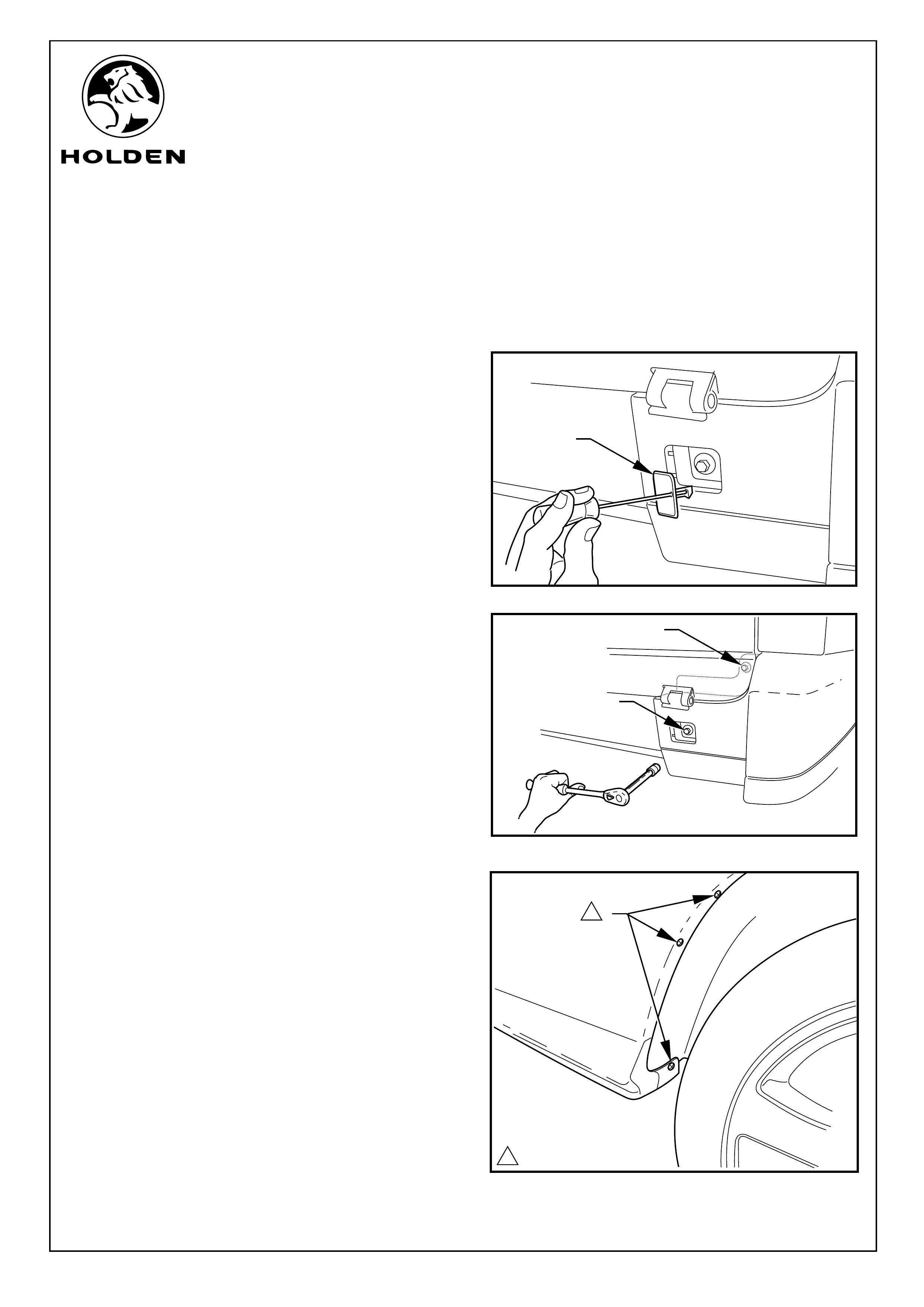
2. Remove the bumperette square cover (1) on the rear
face of the bumperette by pushing a small jewellers
screwdriver into the small hole, apply pressure towards
the centre of the square cover and pull backwards to
remove. Refer to Figure 1.
Refer to Figure 2 for the following:
3. Use a 12mm socket and wrench to remove the
mounting bolts (1).
4. Open the tailgate to remove the second bumperette-
securing bolt.
5. Remove the screws (1)(3 places) at the rear of the rear
wheel arch. Refer to Figure 3.
FIGURE 2
FIGURE 1
1
1
1
1
Page 2 of 12
11.0 - 3.0 Nm
1

FITTING INSTRUCTIONS FOR
COMMODORE UTILITY
REVERSE PARKING SENSOR SYSTEM
FD1305
09NOV04
COPYRIGHT
Reproduction in whole or part
prohibited without written approval
HOLDEN LTD
Division of HOLDEN Ltd ACN 006 893 232
ENSURE DRILL BIT REMAINS
SQUARE WITH BUMPER FASCIA
BUMPER FASCIA
FITTING INSTRUCTIONS: - continued...
6. Remove the black bumperette retaining screw (1) from
the underside of the bumperette by the rear wheel arch
and the painted screws (2) (2 places) at the rear
underside of the bumperette. Refer to Figure 4.
7. Carefully pull the bumperette out to the side of the
vehicle to release the three clips from the fixing rail on
the side of the vehicle.
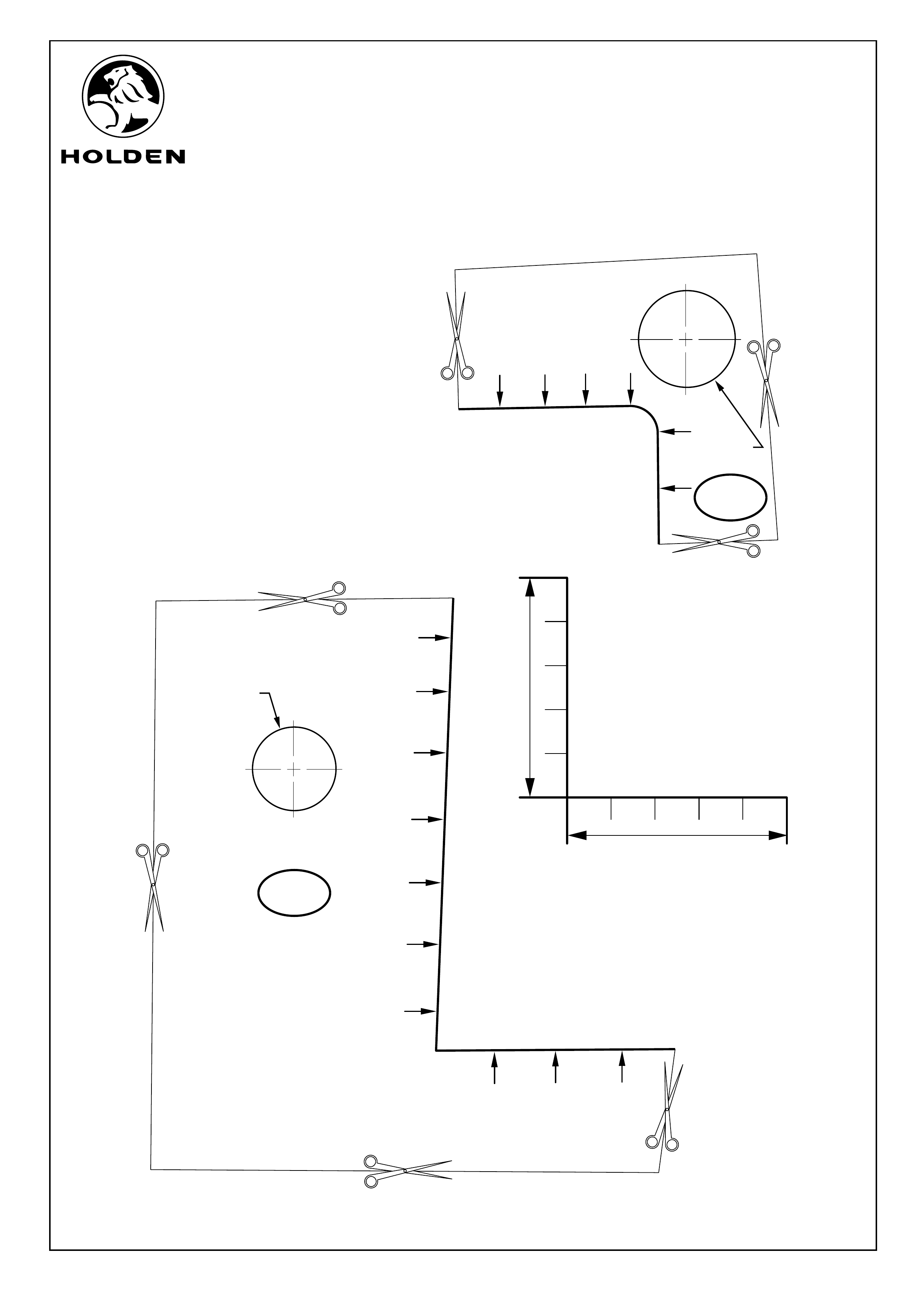
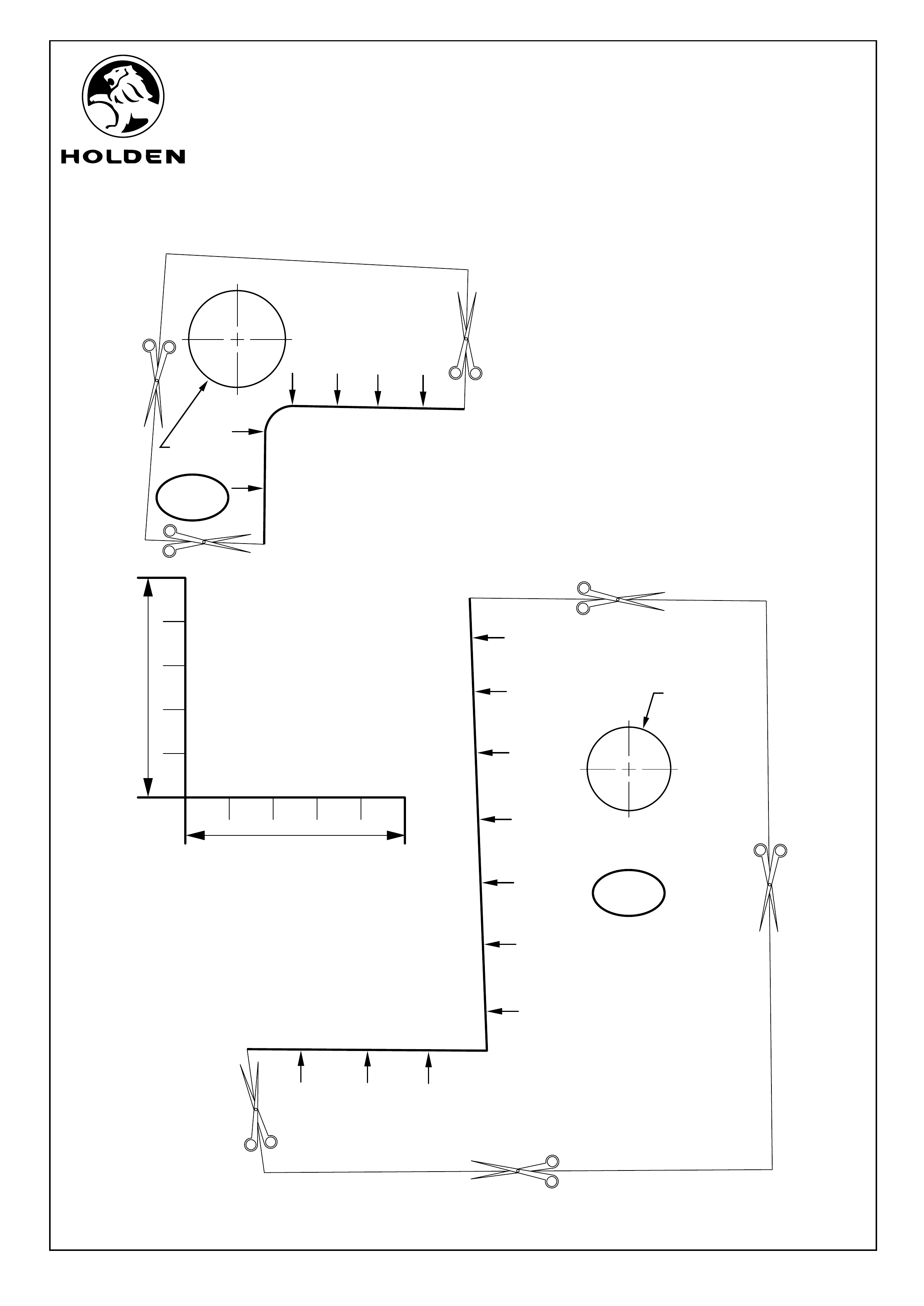
8. Check the scale on the templates at the back of these
instructions for accuracy.
9. Use a pair of scissors to cut out the templates.
Refer to Figure 5 for the following:
10. Align the templates (1 and 3 on the last two pages of
these instructions) on the bumperette as shown on the
template and tape into position.
11. Use point of the spade bit to mark the centre of the hole
on the template.
12. Remove the templates and use the spade bit (1) to make
22.2mm dia. holes (2 places) through the bumperettes
(2).
IMPORTANT:
Use only the spade drill bit as a normal drill bit or
hole saw may damage the bumper fascia.
Ensure the spade drill bit remains square with the
bumper fascia.
Use 1,500 - 2,000 RPM drill speed only to avoid
damaging the bumper fascia.
Refer to Figure 6 for the following:
13. Align the template (2 and 4 on the last two pages of these
instructions) to the rear vehicle panel as shown on the
template and tape into position.
14. Use a 19mm hole saw to drill out the hole.
15. Remove sharp edges with a file.
16. With a magnetic wand remove any swarf and the
circular core from the hole.
17. Paint exposed metal with a high Zinc content corrosion
protection paint.
21
FIGURE 6
FIGURE 5
FIGURE 4
Page 3 of 12
11.0 - 3.0 Nm
1
FITTING INSTRUCTIONS FOR
COMMODORE UTILITY
REVERSE PARKING SENSOR SYSTEM
FD1305
09NOV04
COPYRIGHT
Reproduction in whole or part
prohibited without written approval
HOLDEN LTD
Division of HOLDEN Ltd ACN 006 893 232
Page 4 of 12
FITTING INSTRUCTIONS: - continued...
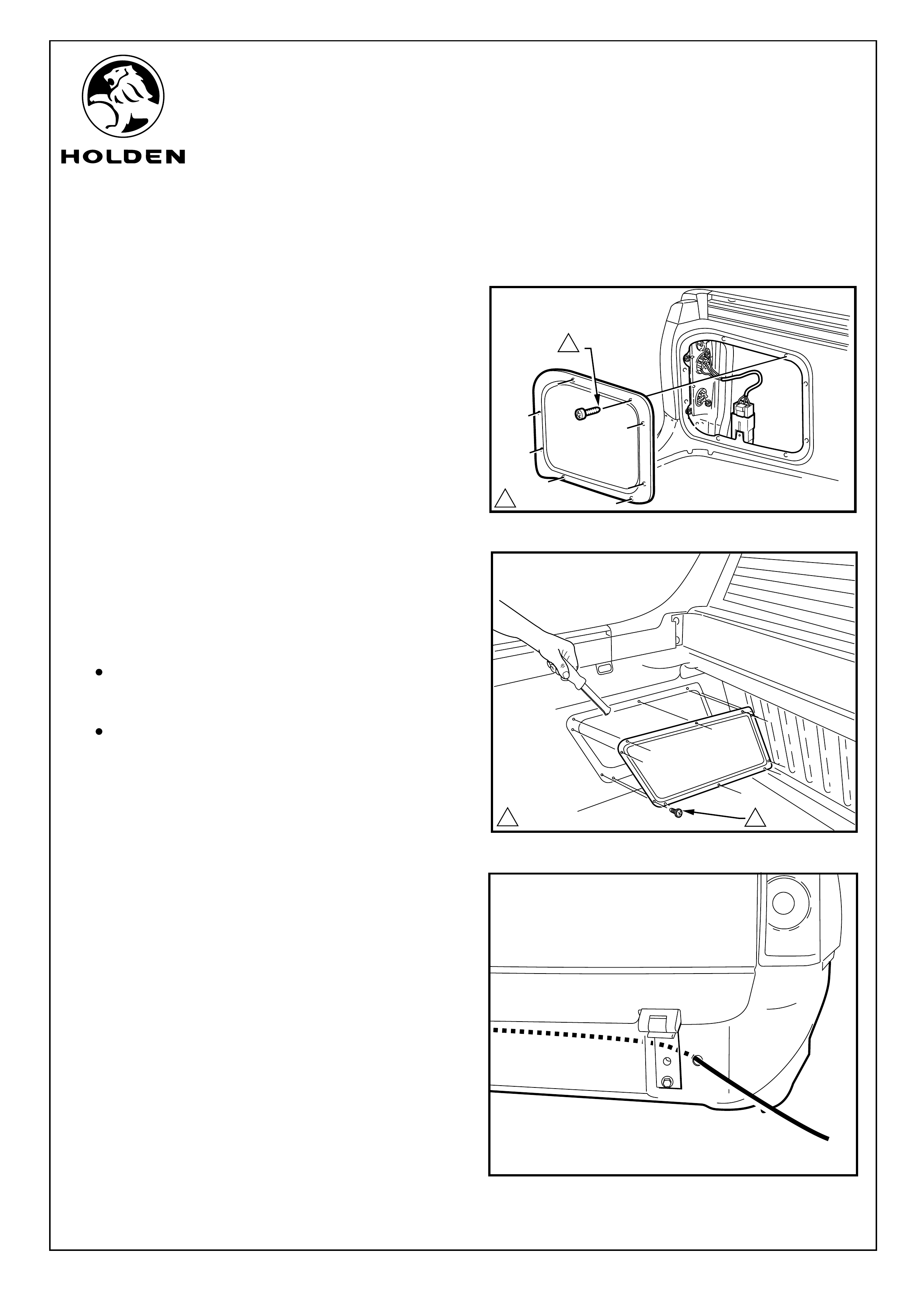
18. Remove the screws (8 screws) retaining the passenger
side inner tail light access cover. Refer to Figure 7.
Refer to Figure 8 for the following:
19. Remove the screws (10 screws) retaining the inner front
tray side access cover.
20. Use a trim removal tool carefully work around the panel
to release the sealant around the edge of the panel.
NOTE:
Cover the tray floor to prevent the sealant from
contacting the body of the vehicle when removing the
panel. Clean any sealant off the body.
Use a soft workshop cloth under the trim removal tool
to prevent damaging the vehicle body.
21. Feed a semi rigid guide through the hole on the driver
side across to the passenger's side of the vehicle. Refer
to Figure 9.
22. Carefully pass the guide wire through the passenger
side tail light cavity and into the tray.
1
11.0 - 3.0 Nm
FIGURE 9
FIGURE 8
FIGURE 7
1
11.0 - 3.0 Nm
FITTING INSTRUCTIONS FOR
COMMODORE UTILITY
REVERSE PARKING SENSOR SYSTEM
FD1305
09NOV04
COPYRIGHT
Reproduction in whole or part
prohibited without written approval
HOLDEN LTD
Division of HOLDEN Ltd ACN 006 893 232
FITTING INSTRUCTIONS: - continued...
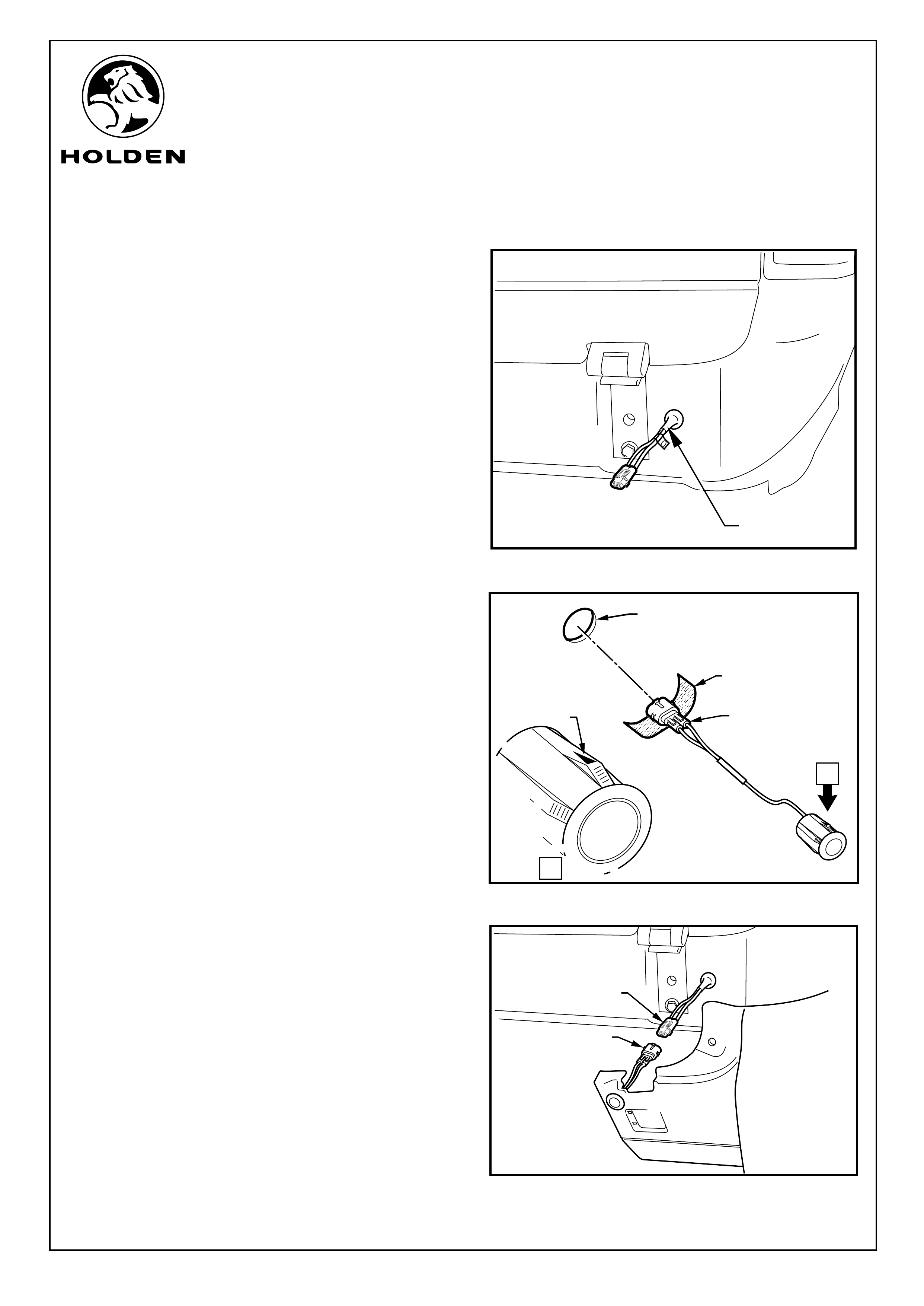
23. Tape the (CR) sensor connection on the RPS sensor
harness to the guide wire and with the aid of an
assistant, pull the guide wire back out of the driver's side
hole. Pull the sensor connection through until the
grommet sleeve comes through the hole. Holding the
grommet sleeve (1) pull the grommet into position.
24. Find the passenger side sensor connector and carefully
guide it through the passenger side hole. From outside
of the vehicle pull the grommet into position.
NOTE: Steps 25 - 30 to be repeated on both sides of the
vehicle.
Refer to Figure 8 for the following:
25. Peel the protective backing off the foam strips (1)
supplied and wrap firmly around each sensors male
connector (2).
26. Pass the male connectors through the bumperette
holes (3) and with the arrow (4) on the sensor body
facing up, press fit the reverse parking sensors to sit
flush with the fascia.
Refer to Figure 24 for the following:
27. Offer the bumperette up to the vehicle and connect the
sensor connector (1) to the RPS harness connector (2).
28. Push the three clips on the bumperette into the body
fixing rail.
29. Ensure the sensor wiring is not trapped between the
body and bumperette mounting point.
30. Refit all bumperette fixings.
2
1
3
4
CR
1
A
VIEW A
FIGURE 9
FIGURE 8
FIGURE 7
1
2
Page 5 of 12

FITTING INSTRUCTIONS FOR
COMMODORE UTILITY
REVERSE PARKING SENSOR SYSTEM
FD1305
09NOV04
COPYRIGHT
Reproduction in whole or part
prohibited without written approval
HOLDEN LTD
Division of HOLDEN Ltd ACN 006 893 232
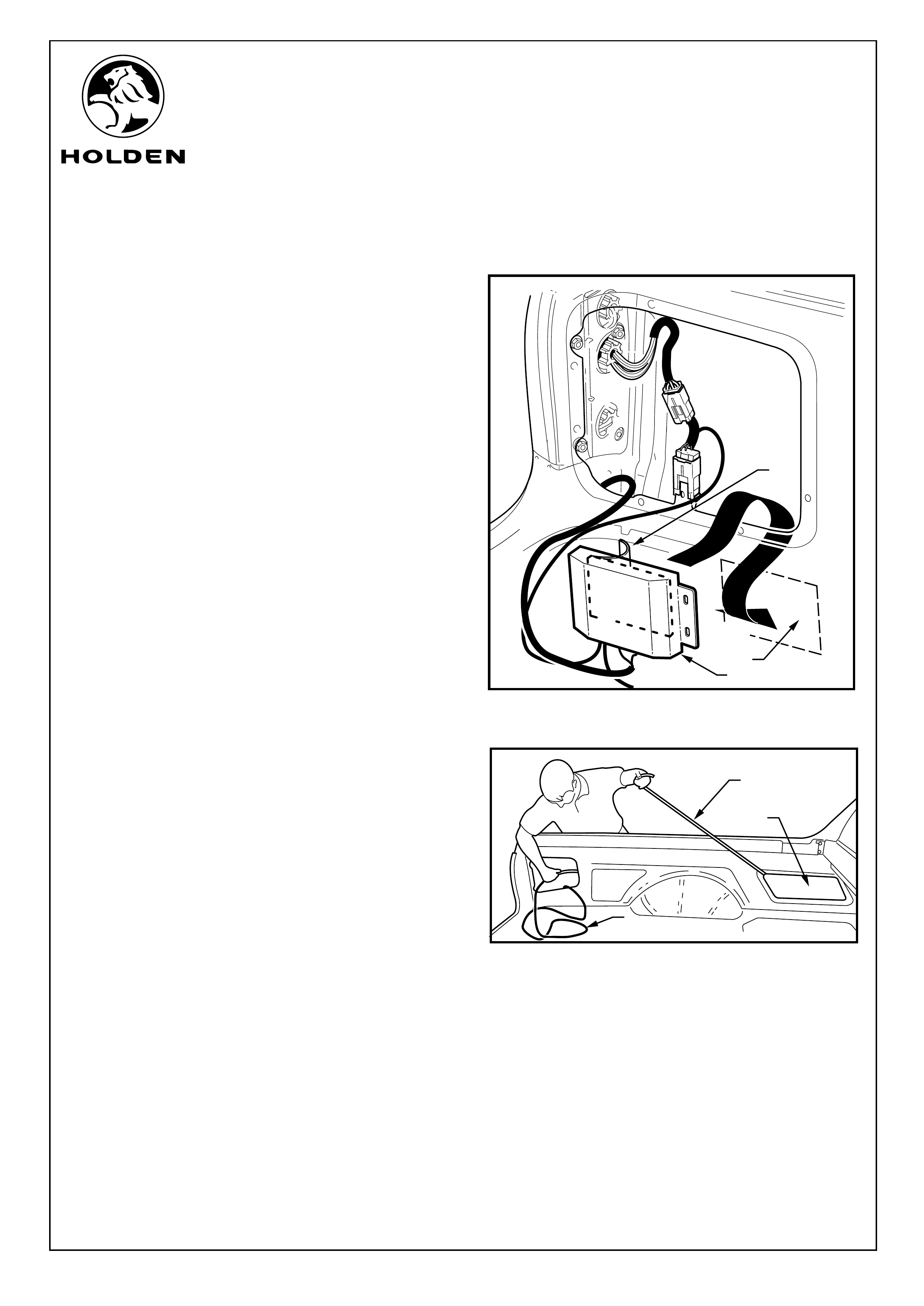
FITTING INSTRUCTIONS: - continued...
31. Use the cleaning pad supplied to clean the back of the
RPS module (1) and retain for further use.
32. Peel one side of protective backing (2) from RPS
module velcro (3) and press fit velcro pad firmly to the
back face of the RPS module.
33. Disconnect the passenger side tail light (1) to body
harness connector (2) and insert the RPS patch harness
(3) between them.
Refer to Figure 12 for the following:
34. Connect the patch harness power connector (1) into the
RPS buzzer harness (2). Connect the 4-way RPS
buzzer connector (3) into the RPS module (4).
35. Connect the two 3-way main RPS harness (5) into the
RPS module.
NOTE: Ensure each tagged wire and connector is
installed in its corresponding connector as marked on
the RPS module.
CL
CR
FIGURE 11
FIGURE 10
1
3
2
1
3
2
FIGURE 12
1
2
3
4
5
Page 6 of 12
FITTING INSTRUCTIONS FOR
COMMODORE UTILITY
REVERSE PARKING SENSOR SYSTEM
FD1305
09NOV04
COPYRIGHT
Reproduction in whole or part
prohibited without written approval
HOLDEN LTD
Division of HOLDEN Ltd ACN 006 893 232
Page 7 of 12
FITTING INSTRUCTIONS: - continued...
Refer to Figure 13 for the following:
36. Use the cleaning pad to clean the outer skin (1) of the
vehicle on the flat area below the zone covered by the
bumperette.
37. Peel the backing (2) off the remaining side of the velcro
pad. Press fit the RPS module onto left hand side inner
sill with the connections facing down.
38. Apply pressure to the RPS module to ensure a secure
fit and full adhesion.
Refer to Figure 14 for the following:
39. Feed the semi rigid guide wire (1) into the passenger
tail light cavity over the top of the wheel arch and out
into the vehicle tray through the inner front cargo area
access aperture (2).
40. Tape the buzzer connector (3) to the semi rigid guide
wire and pull the buzzer wire through to the inner front
tray side access aperture.
3
FIGURE 13
FIGURE 14
1
2
1
2
3
FITTING INSTRUCTIONS FOR
COMMODORE UTILITY
REVERSE PARKING SENSOR SYSTEM
FD1305
09NOV04
COPYRIGHT
Reproduction in whole or part
prohibited without written approval
HOLDEN LTD
Division of HOLDEN Ltd ACN 006 893 232
Page 8 of 12
2
1
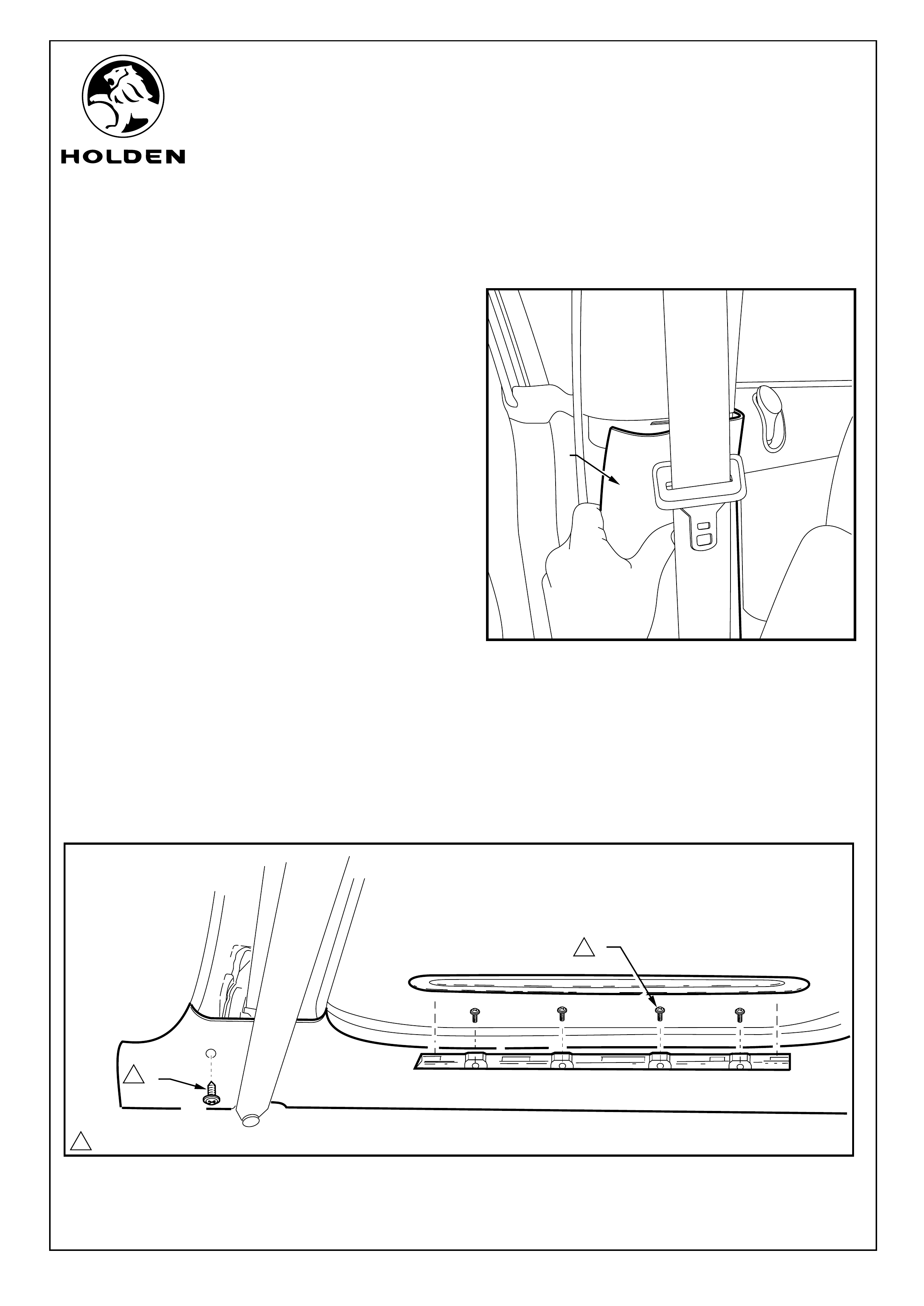
FITTING INSTRUCTIONS: - continued...
41. Pull off the passenger side lower “B” pillar trim panel
(1). Refer to Figure 15.
Refer to Figure 16 for the following:
42. Remove the passenger side screw covers from the
door aperture sill trim.
43. Remove the Torx screws (1) (4 places) and the Torx
screw (2) on the side of the sill trim at the “B” pillar.
Remove the sill trim from vehicle.
1
FIGURE 15
FIGURE 16
11.0 - 3.0 Nm
1
1
FITTING INSTRUCTIONS FOR
COMMODORE UTILITY
REVERSE PARKING SENSOR SYSTEM
FD1305
09NOV04
COPYRIGHT
Reproduction in whole or part
prohibited without written approval
HOLDEN LTD
Division of HOLDEN Ltd ACN 006 893 232
FITTING INSTRUCTIONS: - continued...
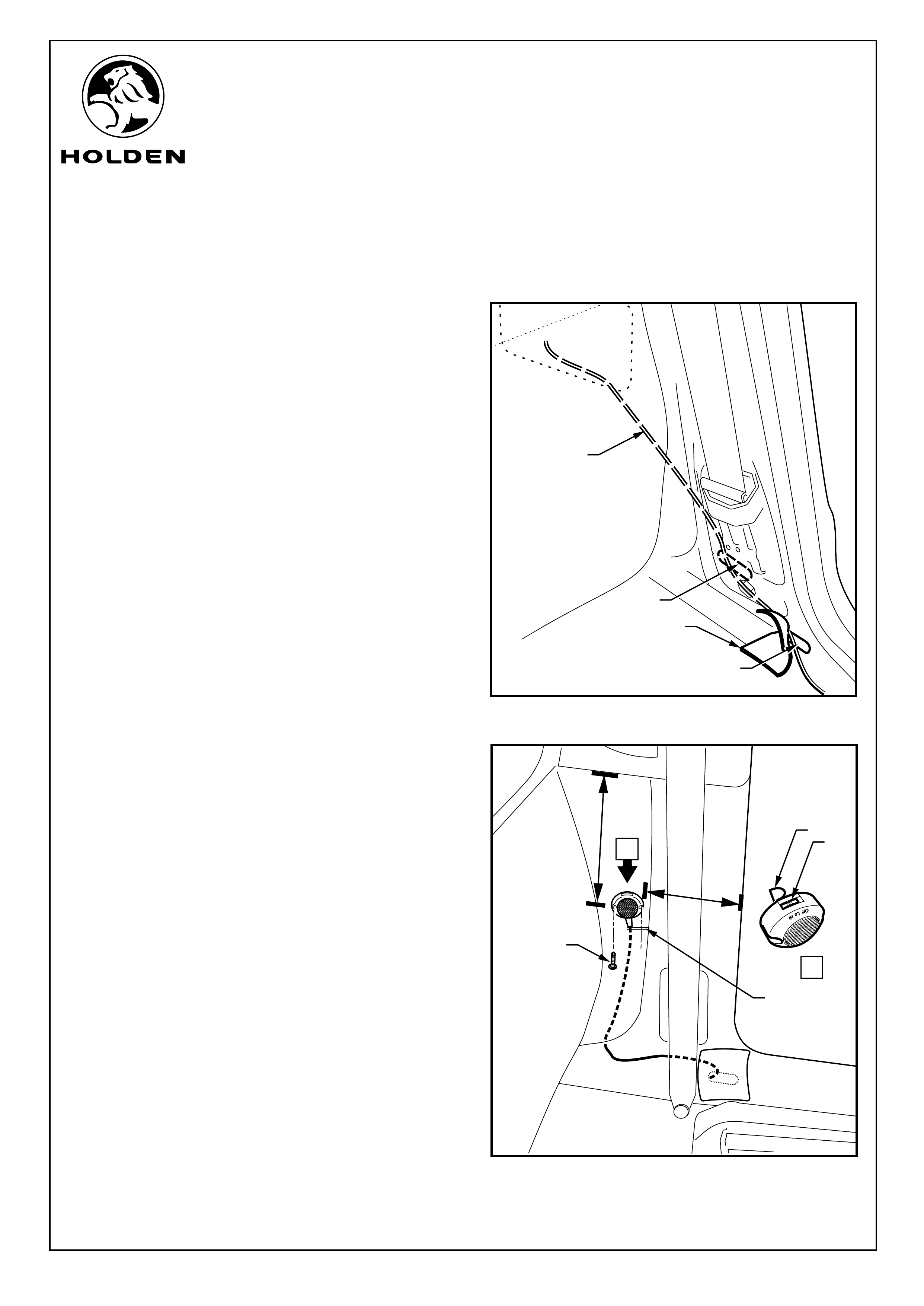
Refer to Figure 17 for the following:
44. Remove the aluminium patch (1) at the base of the “B”
pillar and retain.
45. Feed the semi ridged guide wire (2) through the hole (3)
into the cavity towards the rear of the vehicle feel for the
second hole (4) leading to the outer skin of the vehicle.
46. Locate the guide wire through the inner front cargo
area access aperture.
47. Tape the buzzer to the guide wire and pull the buzzer
connection through into the vehicle passenger area.
Refer to Figure 18 for the following:
48. Connect the buzzer and set the buzzer to low (1).
Remove the top part of the velcro (2) from the velcro
hooks.
49. To position the buzzer, measure 280mm (3) down from
the base of the upper rear quarter light trim and 160mm
(4) back from the edge of the rear of the doorframe.
Secure the buzzer onto the side carpet with the Velcro.
50. Use the two self-drilling screws (5) to permanently fix
the buzzer.
51. Make a slit (6) in the side carpet at the bottom of the
buzzer harness connector and slide the wire into the
slit, run the wire behind the carpet.
52. Refit the aluminium patch back over the access hole
and refit the vehicle trim.
1
2
3
4
A
VIEW A
1
2
3
4
5
6
Page 9 of 12
FIGURE 17
FIGURE 18
FITTING INSTRUCTIONS FOR
COMMODORE UTILITY
REVERSE PARKING SENSOR SYSTEM
FD1305
09NOV04
COPYRIGHT
Reproduction in whole or part
prohibited without written approval
HOLDEN LTD
Division of HOLDEN Ltd ACN 006 893 232
FITTING INSTRUCTIONS: - continued...
53. Locate a suitable position for the caution label (above
tyre placard on drivers side door). Clean the area using
the cleaning pad. Attach the caution label.
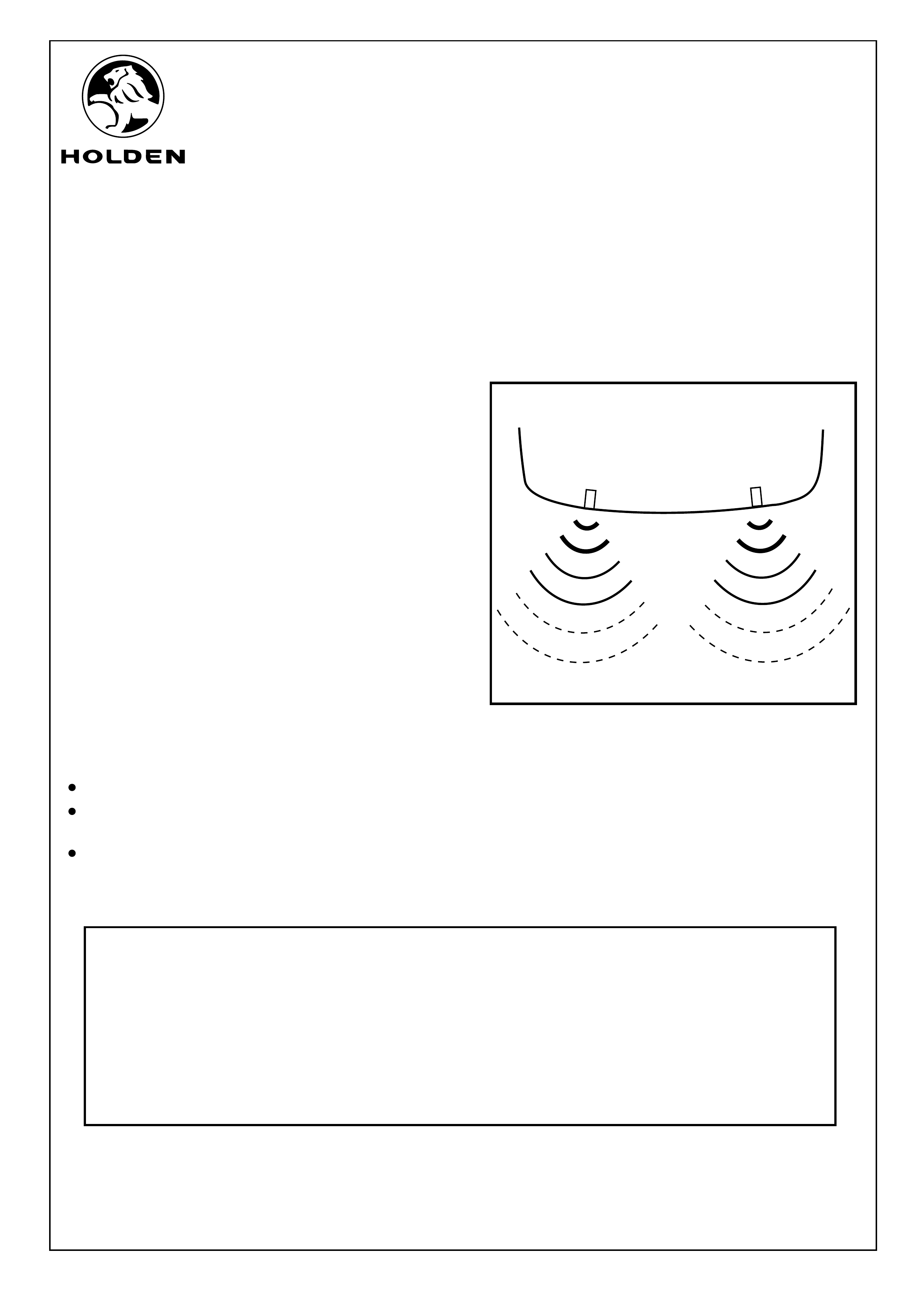
Refer to Figure 19 for the following:
54. Test the reverse parking sensor system for correct
operation as follows:
a. Turn the ignition to the “ON” position (engine not
running).
b. Place the gear lever in reverse (R). Two beeps from
the buzzer should be heard indicating the system is
activated.
c. From behind the vehicle, walk towards each sensor.
d. The two sensors have 3 stages.
NOTE: Refer to the owners manual for further
information and trouble shooting.
e. Turn the ignition to the “OFF” position.
55. Refit all removed parts in the reverse order to removal
and torque fasteners to specifications.
56. Place fitting instructions in the glovebox.
IMPORTANT:
DO NOT paint over the reverse parking sensor.
Ensure the reverse parking sensor remains clean
and free from road grime, mud, car polish etc.
If the sensor or the groove on the sensor surface
becomes contaminated, the performance may be
affected.
FIGURE 19
Page 10 of 12
PARTS LIST
PART NUMBER DESCRIPTION QUANTITY
92171981 Reverse Parking Assist 1
92147939 Sensors Head - RPA 2
92147940 Module - RPA 1
NS Wiring Harness 1
92147941 Buzzer Unit 1
NS Cable Ties 12
FD1305 Fitting Instructions 1
FD796 Proof of Warranty Card 1
FITTING INSTRUCTIONS FOR
COMMODORE UTILITY
REVERSE PARKING SENSOR SYSTEM
FD1305
09NOV04
COPYRIGHT
Reproduction in whole or part
prohibited without written approval
HOLDEN LTD
Division of HOLDEN Ltd ACN 006 893 232
50mm
50mm
L
TEMPLATE 2
(CHASSIS)
LEFT (L)
L
TEMPLATE 1
(FASCIA)
LEFT (L)
HOLE SAW
19.0mm DIA.
SPADE BIT
22.2mm DIA.
Page 11 of 12
CHECK SCALE BEFORE USING TEMPLATE
FITTING INSTRUCTIONS FOR
COMMODORE UTILITY
REVERSE PARKING SENSOR SYSTEM
FD1305
09NOV04
COPYRIGHT
Reproduction in whole or part
prohibited without written approval
HOLDEN LTD
Division of HOLDEN Ltd ACN 006 893 232
R
TEMPLATE 4
(CHASSIS)
RIGHT (R)
R
TEMPLATE 3
(FASCIA)
RIGHT (R)
50mm
50mm
HOLE SAW
19.0mm DIA.
SPADE BIT
22.2mm DIA.
Page 12 of 12
CHECK SCALE BEFORE USING TEMPLATE