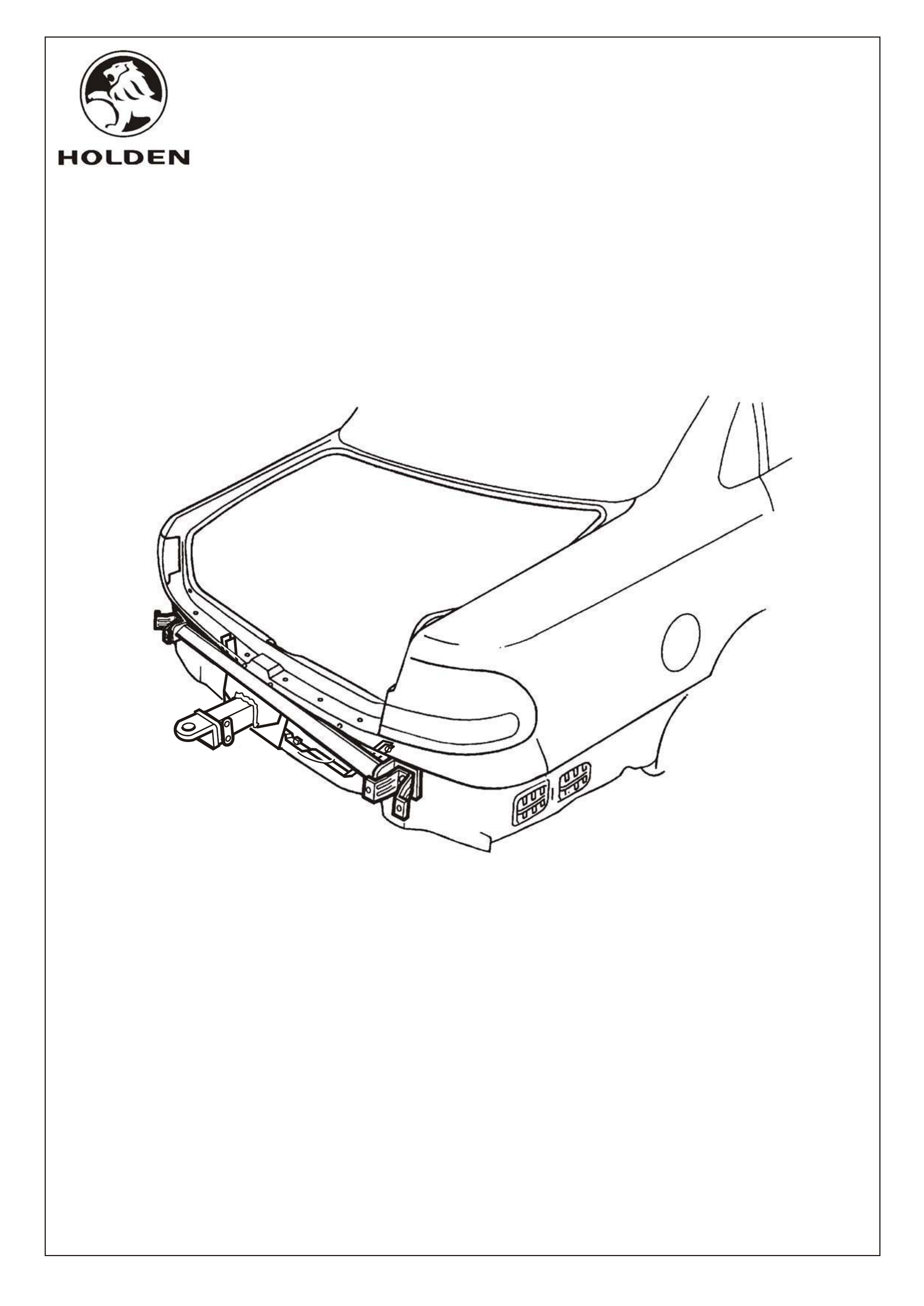
FITTING INSTRUCTIONS FOR
WH STATESMAN & CAPRICE (V6)
2100KG TOW BAR KIT
Part Number 92143026
FD
09AU00
XXX
COPYRIGHT
Page 1 of 8
FDXXX-1
HOLDEN SERVICE PARTS OPERATIONS
Reproduction in whole or part
prohibited without written approval
Division of HOLDEN Ltd ACN 006 893 232
SMALL PARTS KIT
COVERBALL 92140106
92143024
92140068 TOW BALL ASSEMBLY (CHROME)
92140148 TRAILER WIRING HARNESS - ROUND 7 PIN (SMALL PIN WITH BACKING PLATE)
92140147 TRAILER WIRING HARNESS - ROUND 7 PIN (LARGE PIN)
92140088 TRAILER WIRING HARNESS - FLAT 7 PIN
92140101 PACKAGE - LOAD DISTRIBUTION HITCH (ADJUSTABLE)
NOT INCLUDED IN TOW BAR PACKAGE, BUT AVAILABLE SEPARATELY:
NOT REQUIRED
REFER FD907 & FD908

2100KG TOW BAR FITTING INSTRUCTIONS
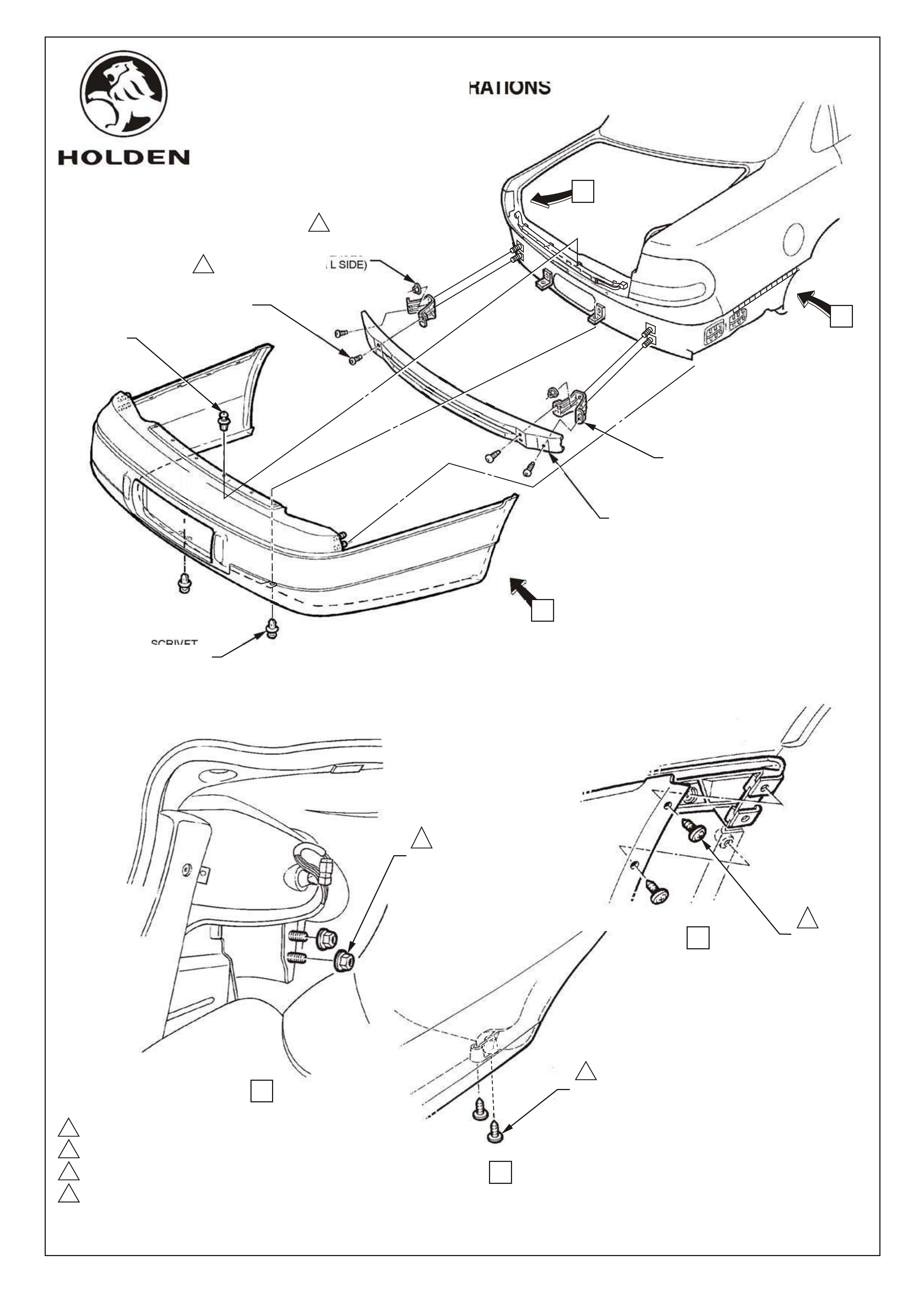
REAR BUMPER BAR SUPPORT BEAM & BRACKETS REMOVAL
Remove spare wheel cover and spare wheel from rear compartment.
Fold side carpets back from rear corners of boot compartment to access nuts securing bumper to body
refer figure 1, view A.
Remove nuts (2 places each side) refer figure 1, view A
Remove 4 scrivets at upper edge of facia, refer figure 1.
Remove 2 scrivets, lower facia edge, refer figure 1.
Remove 8 screws, facia to rear edge of wheelhouse, refer figure 1, views B and C.
With facia supported, pull facia sides outward disconnecting facia from side supports and slide rearwards
removing facia, refer figure 1.
Remove bolts securing bumper support beam to brackets. Refer figure 1.
Remove 4 nuts securing bumper support beam brackets to vehicle (4 places) and remove brackets,
refer figure 1.
1.
2.
3.
4.
5.
6.
7.
8.
9.
FD
09AU00
XXX
COPYRIGHT
Page 2 of 8
FD -2XXX
HOLDEN SERVICE PARTS OPERATIONS
Reproduction in whole or part
prohibited without written approval
Division of HOLDEN Ltd ACN 006 893 232
NOT REQUIRED
REFER FD907 & FD908
1,0 - 3,0 Nm
6,0 - 9,0 Nm
35,0 - 52,0 Nm
50,0 - 80,0 Nm
4
3
2
1
VIEW B
1
SCREW
(2 PLACES
R & L SIDE)
VIEW A
2
NUT
(2 PLACES
R & L SIDE)
FD
09AU00
XXX
Figure 1
Page 3 of 8
FD -3XXX
COPYRIGHT
HOLDEN SERVICE PARTS OPERATIONS
Reproduction in whole or part
prohibited without written approval
Division of HOLDEN Ltd ACN 006 893 232
NUT
(2 PLACES
R & L SIDE)
REAR BEAM
MOUNTING BRACKET
REAR BUMPER
SUPPORT BEAM ASM.
SCRIVET
(2 PLACES)
BOLT
(2 PLACES
R & L SIDE)
3
4
C
A
B
SCRIVET
(4 PLACES)
VIEW C
SCREW
(2 PLACES)
R & L SIDE
1
NOT REQUIRED
REFER FD907 & FD908

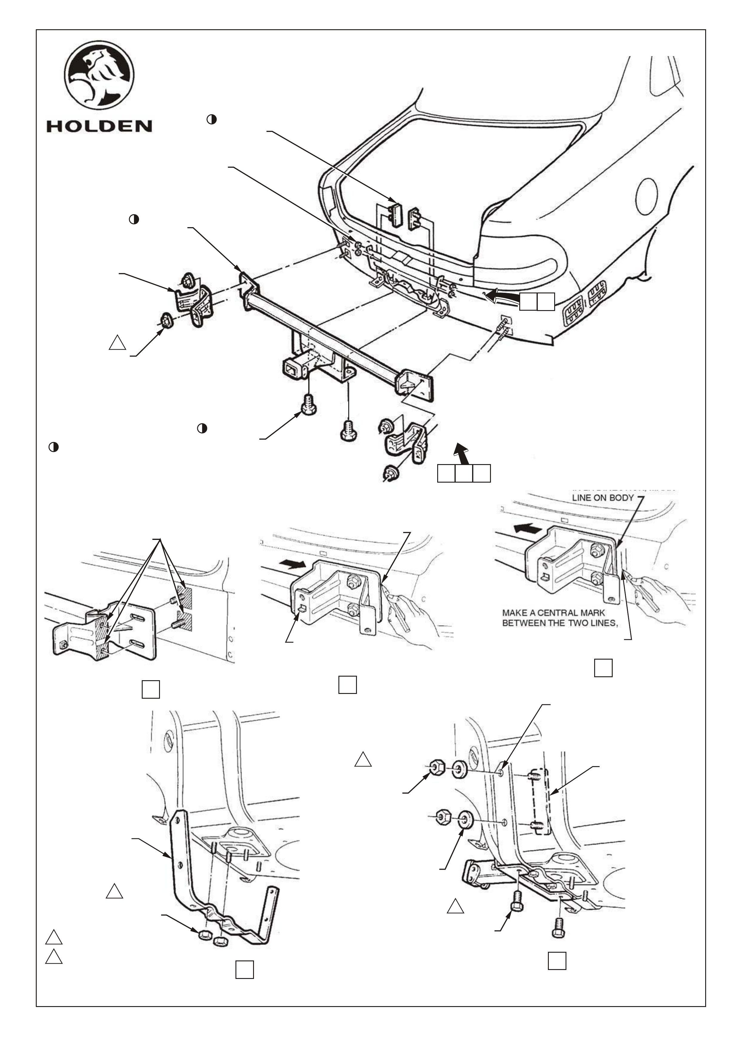
TOW BAR INSTALLATION
Smear a thin film of grease to bare metal exposed by removal of brackets, to vehicle body and rear face of
bracket to prevent corrosion, refer figure 2, view A.
Install spare wheel well brace assembly to underside of spare wheel well using two existing rearmost
weldstuds, refer figure 2, view D.
Loosely fit two M10 nuts to weld studs.
Install tow bar to 4 beam support studs, refit beam support brackets over tow bar mounting plates, fit nuts
and hand tighten (4 places).
NOTE : Brackets must be installed with tab on flange inboard of vehicle refer figure 2, view B.
Loosely fit two M10 bolts to attach tow bar main assembly to spare wheel well brace assembly.
IMPORTANT: Due to elongated holes in tow bar mounting plates, tow bar will have 10-15mm sideways
travel on rear of car. Tow bar must be accurately centralised on vehicle to ensure bumper
facia cutout aligns with tow bar tongue upon reassembly.
To centralise bar, first slide bar to extremity of travel to RH side of vehicle and mark position of edge of RH
mounting plate on body, refer figure 2, view B.
Slide bar across to extremity of travel to LH side of vehicle and mark RH mounting plate edge position
on body, refer figure 2, view C.
Make a central mark between these two lines (this will centre towbar) & reposition towbar to centre
line.
Tighten nuts securing beam support brackets and tow bar mounts to body, 50 - 80Nm (4 places),
refer figure 2.
Tighten nuts securing spare wheel well brace assembly to underbody weld studs, 30 - 40Nm,
(2 places)
Tighten bolts securing main tow bar assembly to spare wheel well brace assembly, 30 - 40Nm,
(2 places)
Use spare wheel well brace assembly as a template to drill two 10,0 dia. holes each side of spare
wheel well, refer figure 2, view E.
WARNING : Be sure spare wheel has been removed from spare wheel well before drilling holes.
Apply silicone or butyl sealer to holes for water sealing & corrosion protection purposes, 4 places.
Install two adhesive backed stud plates from inside spare wheel well, through holes in wheel well and spare
wheel well brace assembly.
From underside of vehicle attach flat washers and M10 nuts to stud plate studs,(4 places) refer figure 2,
view E.
Tighten spare wheel well brace assembly to stud plate nuts 30 - 40Nm (4 places).
Refit bumper beam, and tighten 35 - 52Nm.
10.
11.
12.
13.
14.
15.
16.
17.
18.
19.
20.
21.
22.
23.
24.
25.
26.
FD
09AU00
XXX
COPYRIGHT
Page 4 of 8
FD -4XXX
HOLDEN SERVICE PARTS OPERATIONS
Reproduction in whole or part
prohibited without written approval
Division of HOLDEN Ltd ACN 006 893 232
NOT REQUIRED
REFER FD907 & FD908
1
2
30,0 - 40,0 Nm
50,0 - 80,0 Nm
SLIDE TOW BAR TO
EXTREMITY OF TRAVEL
IN RH DIRECTION, MARK
LINE ON BODY
RH SHOWN
BRACKET MUST
BE INSTALLED
WITH TAB INBOARD
VIEW B
SLIDE TOW BAR TO
EXTREMITY OF TRAVEL
IN LH DIRECTION, MARK
LINE ON BODY
MAKE A CENTRAL MARK
BETWEEN THE TWO LINES,
ALIGN TOW BAR EDGE TO
THIS MARK TO CENTRALISE
TOW BAR
VIEW C
VIEW D
COAT BARE METAL
SURFACES WITH A
THIN FILM OF GREASE
RH SHOWN
VIEW A
NUT
(2 PLACES)
1
SPARE WHEEL
WELL BRACE
ASSEMBLY.
VIEW E
1
STUD PLATE
(2 PLACES)
FLAT
WASHER
(2 PLACES
R & L SIDE)
NUT
(2 PLACES
R & L SIDE)
1
BOLT
(2 PLACES)
USE SPARE WHEEL WELL BRACE
ASSEMBLY AS A TEMPLATE TO
DRILL 10.0 DIA. HOLES
(2 PLACES EACH SIDE)
FD
09AU00
XXX
Figure 2
COPYRIGHT
Page 5 of 8
HOLDEN SERVICE PARTS OPERATIONS
Reproduction in whole or part
prohibited without written approval
Division of HOLDEN Ltd ACN 006 893 232
REAR BUMPER
BEAM SUPPORT
BRACKET
NUT
(2 PLACES
R &L SIDE)
2
PART OF TOW BAR PACKAGE
BOLT
(2 PLACES)
NUT
(2 PLACES)
TOW BAR
ASSEMBLY
C
A B
E
D
STUD PLATE
(2 PLACES)
FD -5XXX
NOT REQUIRED
REFER FD907 & FD908

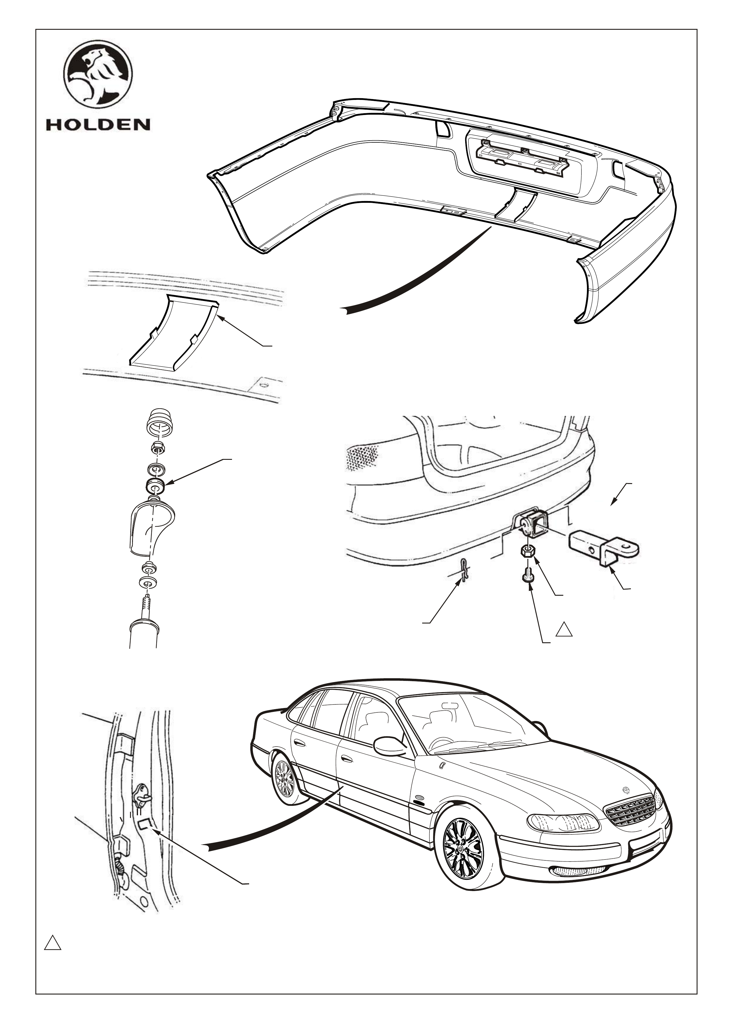
Install tow bar tongue to tow bar assembly using retainer pin and safety clip, refer figure 3.
NOTE : Align studs on facia correctly through holes in body, below tail lights.
Reinstall facia in reverse to removal procedure.
hitch mounting tube, refer figure 3.
Before facia refit, knock out section in centre of bumper facia to allow protrusion of bar
Clean surface of driver's side B pillar and apply ADR label, refer figure 3.
duty insulators supplied in towing package, refer figure 3.
Replace existing shock absorber top mount insulators (rubber) with yellow polyurethane heavy
Install trailer wiring harness as per fitting instructions included in trailer wiring harness package
33.
32.
31.
Install anti-rattle bolt and nut. Tighten nut 5 - 10Nm.
IMPORTANT : Anti-rattle bolt and nut must only be used when tow bar is unladen. Remove
anti-rattle bolt and nut when tow bar is loaded.
30
29.
28.
27.
FD
09AU00
XXX
COPYRIGHT
Page 6 of 8
FD -6XXX
HOLDEN SERVICE PARTS OPERATIONS
Reproduction in whole or part
prohibited without written approval
Division of HOLDEN Ltd ACN 006 893 232
NOTE: Once tow bar installation is complete, place Fitting Instruction booklet in glove box of vehicle.
NOT REQUIRED
REFER FD907 & FD908
5 - 10 Nm
1
1
SAFETY CLIP
FD
09AU00
XXX
Figure 3
COPYRIGHT
Page 7 of 8
FD -7XXX
HOLDEN SERVICE PARTS OPERATIONS
Reproduction in whole or part
prohibited without written approval
Division of HOLDEN Ltd ACN 006 893 232
WIPE SURFACE CLEAN PRIOR
TO APPLICATION OF ADR LABEL
BUMPER FACIA
KNOCKOUT
TOW BAR
TONGUE
NUT M10
ANTI -RATTLE BOLT M10 x 25
(ONLY USE WHEN UNLOADED)
TOP
INSULATOR
RETAINER
PIN
NOT REQUIRED
REFER FD907 & FD908

2100 KG TOW BAR KIT
FOR WH STATESMAN & CAPRICE (V6)
Part number 92143026
PART NO. DESCRIPTION QUANTITY
92076518 TOW BAR MAIN ASSEMBLY 1
92054275 BRACE ASSEMBLY - SPARE WHEEL WELL 1
NUT M10 6
BOLT M10 x 25 2
M10 - STUD PLATE ASM. 2
BOLT M12 x 25 2
FLAT WASHER M10 8
BOLT ANTI-RATTLE M10 x 25mm 1
NUT M10 1
92077203 'D' RING SAFETY SHACKLE 2
ADR LABEL 1
FD TOW BAR FITTING INSTRUCTION BOOKLET 1
FD796 WARRANTY CARD 1
92047624 PACKAGE - TONGUE TOW BAR 1
92140089 INSULATOR - SHOCK ABSORBER TOP MOUNTING 2
92037805 HEAT SHIELDS, SPARE WHEEL WELL 6
92053241 or 92143924 PACKAGE - HEAT SHIELD, CENTRE BEARING 1
92141589 PACKAGE - POWER STEERING FLUID COOLER 1
92059988 TOW BAR PACKAGE CONSISTS OF :
XXX
92140106
92143024 SMALL PARTS KIT
COVERBALL
92140068 TOW BALL ASSEMBLY (CHROME)
92140148 TRAILER WIRING HARNESS - ROUND 7 PIN (SMALL PIN WITH BACKING PLATE)
92140147 TRAILER WIRING HARNESS - ROUND 7 PIN (LARGE PIN)
92140088 TRAILER WIRING HARNESS - FLAT 7 PIN
92140101 PACKAGE - LOAD DISTRIBUTION HITCH (ADJUSTABLE)
NOT INCLUDED IN TOW BAR PACKAGE, BUT AVAILABLE SEPARATELY:
FD
09AU00
XXX
COPYRIGHT
Page 8 of 8
FD -8XXX
HOLDEN SERVICE PARTS OPERATIONS
Reproduction in whole or part
prohibited without written approval
Division of HOLDEN Ltd ACN 006 893 232
PARTS LIST
NOT REQUIRED
REFER FD907 & FD908