FD1100
16SE02
COPYRIGHT
Page 1 of 8
G681
HOLDEN SERVICE PARTS OPERATIONS
Reproduction in whole or part
prohibited without written approval
Division of HOLDEN Ltd ACN 006 893 232
FITTING INSTRUCTIONS FOR
XC COMBO,1000kg TOWBAR PACKAGE
Part No. 92145397

FITTING INSTRUCTIONS:
NOTE: It is recommended to use a 2 post hoist, to ease
towbar assembly installation.
1. Place vehicle in position on hoist. Refer to owners
manual for correct jacking locations. Open the rear
cargo doors and remove the lower rear end trim panel
T25 Torx head screws - 9 places. Refer Figure 1.
Fold back the rear cargo floor carpet.
2. Unclip the rear wheel arch opening trim. Refer Figure 2.
3. Remove the rear bumper fascia, 2 screws and 6
scrivets. Refer Figure 3.
4. Remove the rear bumper fascia crash limiter (T45 x
65mm Torx head bolt and M8 nut - 2 places).
Refer Figure 3.
TOOLS REQUIRED:
2-Post Hoist, Torque Wrench, Socket Set, Spanner Set,
Torx Bit-T25, Torx Bit-T45, Power Drill, 3mm Dia. Drill Bit,
22mm Dia. Hole Saw, 11mm.Dia. Drill Bit and Rust-proof
Paint.
FITTING INSTRUCTIONS FOR
XC COMBO,1000kg TOWBAR PACKAGE
Part No. 92145397
COPYRIGHT
Page 2 of 8
HOLDEN SERVICE PARTS OPERATIONS
Reproduction in whole or part
prohibited without written approval
Division of HOLDEN Ltd ACN 006 893 232
FIGURE 1
FD1100
16SE02
G681
REAR WHEEL ARCH
OPENING TRIM
FIGURE 2
FIGURE 3
REAR
BUMPER
CRASH
LIMITER
T45 x 65MM TORX
HEAD BOLT
SCREW
2 PLACES
SCRIVET
6 PLACES
M8 NUT
2 PLACES
REAR
BUMPER
FASCIA
SCREWS
9 PLACES
REAR END
TRIM PANEL
DRILL A 3.0mm
DIA HOLE 2 PLACES
R & LH SIDE
COPYRIGHT
Page 3 of 8
HOLDEN SERVICE PARTS OPERATIONS
Reproduction in whole or part
prohibited without written approval
Division of HOLDEN Ltd ACN 006 893 232
FD1100
16SE02
FIGURE 4
FIGURE 6
G681
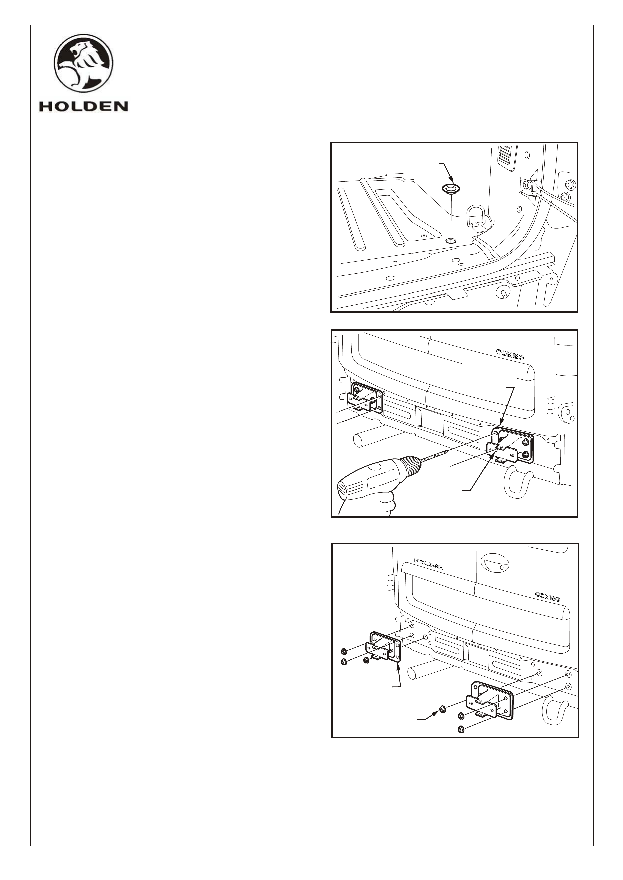
FITTING INSTRUCTIONS: - continued.
5. Remove the left and right-hand side blanking
grommets from the cargo floor near the rear opening.
Refer Figure 4.
NOTE: If the XC combo trailer harness (92146212) is
being fitted, refer to fitting instructions FD1099 at this
point.
6. Using the existing bumper fascia impact absorber
brackets as templates, drill pilot holes in the rear panel
through the inner vacant holes using a 3mm Dia. drill bit
(4 places). Refer Figure 5.
7. Remove the left and right hand side bumper fascia
impact absorber brackets (3 nuts - left and right hand
side). Refer Figure 6.
FIGURE 5
BLANKING
GROMMET
IMPACT
ABSORBER
BRACKET
NUTS
3 PLACES
IMPACT
ABSORBER
BRACKET

COPYRIGHT
Page 4 of 8
HOLDEN SERVICE PARTS OPERATIONS
Reproduction in whole or part
prohibited without written approval
Division of HOLDEN Ltd ACN 006 893 232
FD1100
16SE02
FIGURE 7
FIGURE 8
FIGURE 9
G681
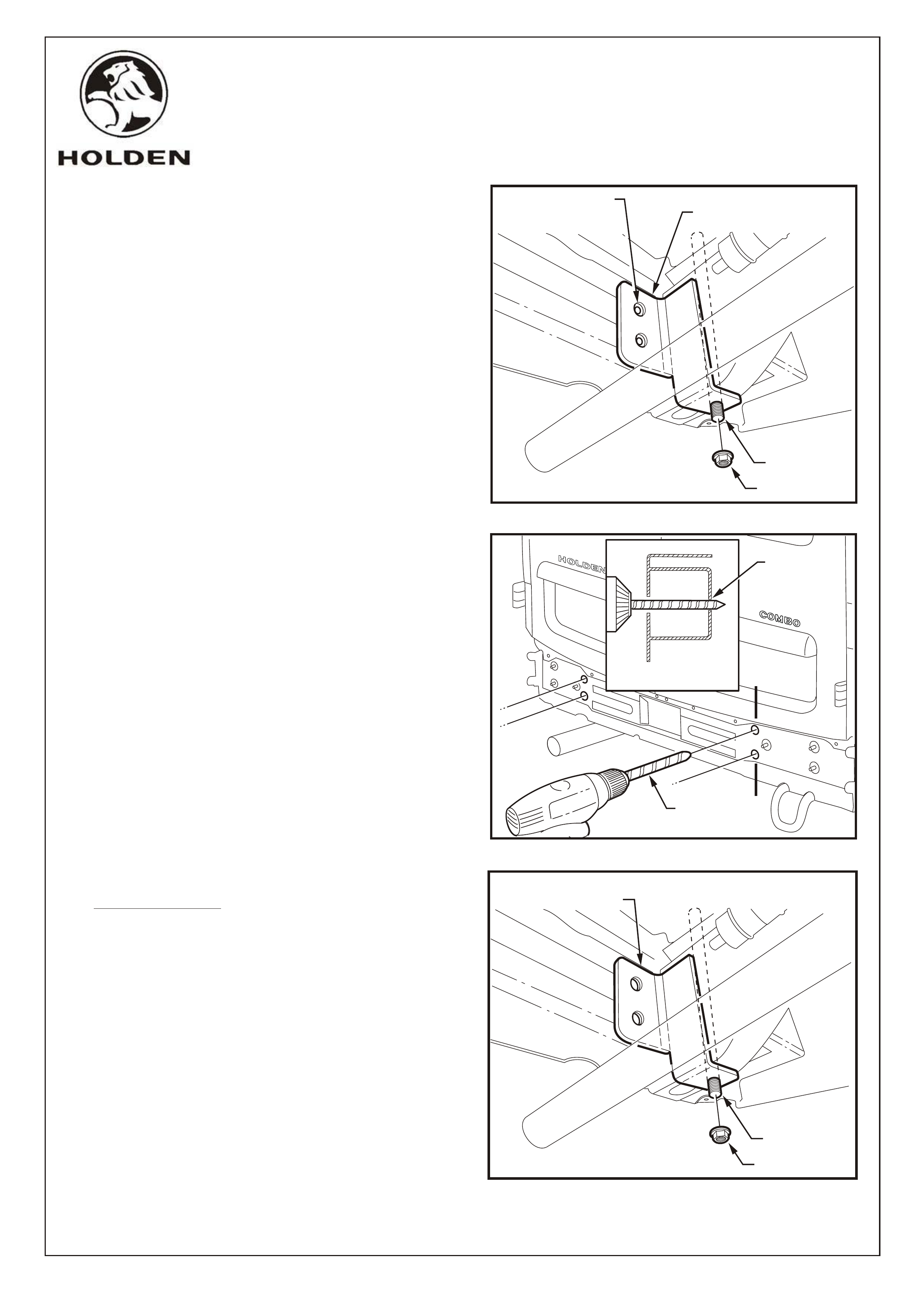
FITTING INSTRUCTIONS: - continued.
8. Using a 22mm Dia. hole saw, enlarge the pilot holes
previously drilled (Step 6) in the rear panel (4 places).
Refer Figure 7.
IMPORTANT: When drilling across the box channel,
the 22mm Dia.hole saw is used for alignment purposes
only, DRILL A PILOT HOLE ONLY.
Ensure the drill bit remains square with the rear of the
vehicle and parallel to the cargo floor.
9. Through the holes drilled in Step 8, and with the 22mm
Dia. hole saw still fitted, drill a PILOT HOLE ONLY
through the opposite side of the box channel. Refer
Figure 8.
10. Assemble the coach bolt, cargo bracket and long
spacer tube (17.3mm OD) and fit to the existing hole in
the cargo floor (left and right-hand sides).
Refer Figure 9.
SECTION A - A A
A
PILOT
HOLE ONLY
SECTION A - A A
A
22.0 mm DIA.
HOLE ONLY
CARGO
BRACKET
COACH
BOLT
SPACER
TUBE
COPYRIGHT
Page 5 of 8
HOLDEN SERVICE PARTS OPERATIONS
Reproduction in whole or part
prohibited without written approval
Division of HOLDEN Ltd ACN 006 893 232
FD1100
16SE02
FIGURE 10
G681
FITTING INSTRUCTIONS: - continued.
11. From beneath the vehicle, temporarily install the
support bracket using M10 flange nut (left and right
hand side). Finger tighten only at this point.
Refer Figure 10.
12. Check that the pilot holes drilled in Step 9 are centred
with the towbar assembly mounting holes in the
support bracket (left and right-hand side).
Remove the support brackets.
If the pilot holes are correct, proceed with the
instructions. If the pilot holes are not correctly
positioned, adjust as necessary.
13. From the rear of the vehicle, enlarge the pilot holes
drilled in Step 11 using an 11mm Dia. drill bit.
Refer Figure 11.
14. Deburr all drilled holes and coat with rust proof paint.
15. Re-fit the support bracket (left and right hand side).
Finger tighten only. Refer Figure 12
COACH BOLT
SUPPORT
BRACKET
M10 FLANGE NUT
SECTION A - A A
A
11.0 mm DIA.
HOLE ONLY
FIGURE 12
COACH BOLT
SUPPORT
BRACKET
M10 FLANGE NUT
FIGURE 11
11.0 mm
DRILL BIT
TOWBAR ASSEMBLY
MOUNTING HOLES
& PILOT HOLES
COPYRIGHT
Page 6 of 8
HOLDEN SERVICE PARTS OPERATIONS
Reproduction in whole or part
prohibited without written approval
Division of HOLDEN Ltd ACN 006 893 232
FD1100
16SE02
FIGURE 14
FIGURE 13
G681
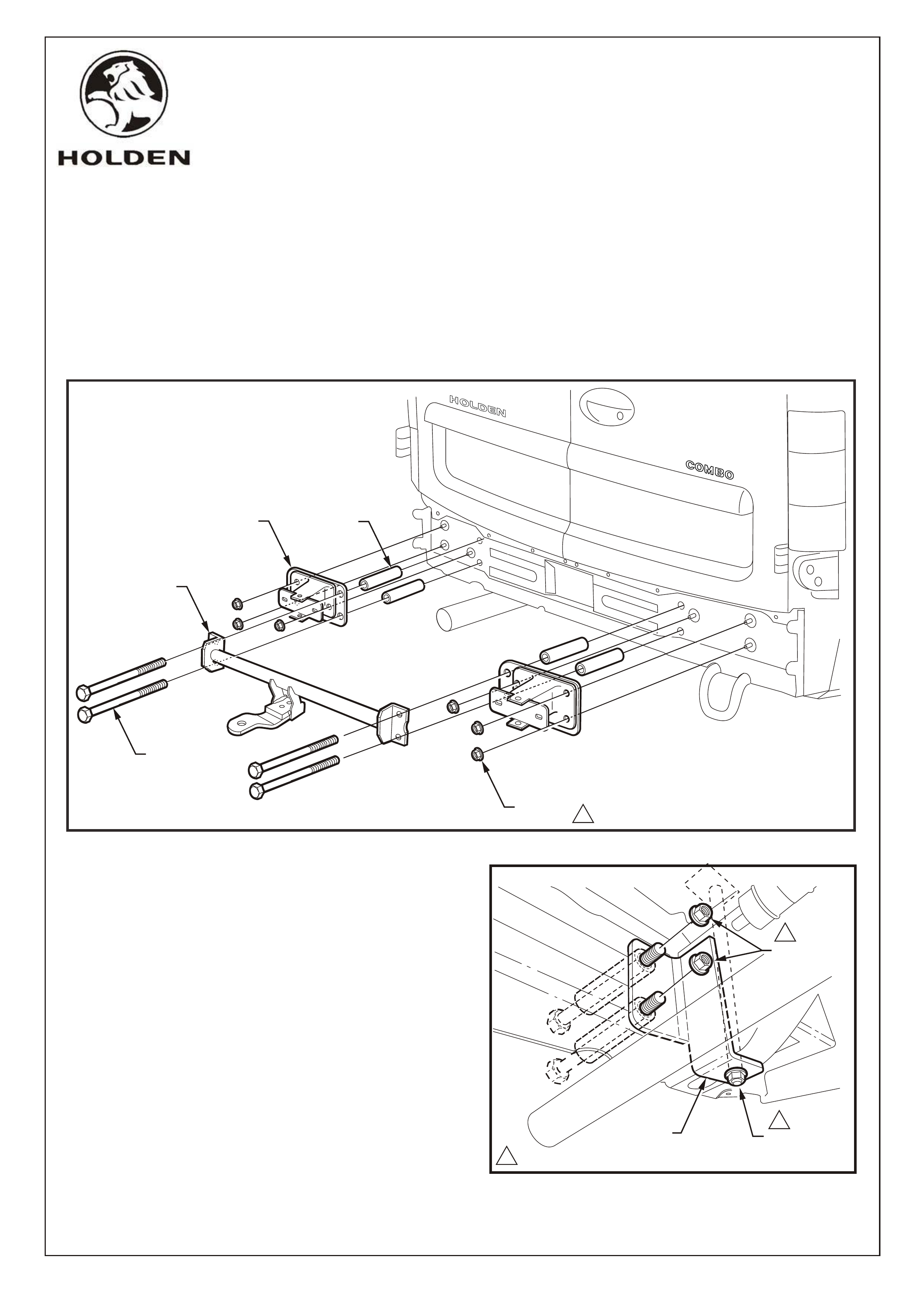
FITTING INSTRUCTIONS: - continued.
16. Assemble the towbar, the bumper fascia impact absorber brackets, the short spacers(22mm OD) and the M10 x 90
bolts.
With assistance, offer the towbar assembly up to the rear panel. Ensure the M10 x 90 bolts pass through the
support brackets fitted behind the box channel and that the impact absorber brackets mount on the original studs.
Refer Figure 13.
NOTE: Loosen the support bracket securing nuts to ease installation if necessary.
17. Reinstall the bumper fascia impact absorber bracket nuts and torque to specifications (3 places - left and right hand
side). Refer Figure 13.
18. Secure the towbar assembly to the support brackets
using M10 flange nuts, 2 places (left and right-hand
side).
Torque M10 flange nuts to specifications (6 places).
Refer Figure 14
144 Nm
IMPACT
ABSORBER
BRACKET
SHORT
SPACER
4 PLACES
M10 x 90
BOLT
4 PLACES
TOWBAR
NUT
6 PLACES 1
SUPPORT
BRACKET M10 FLANGE
NUT
M10 FLANGE
NUTS
1
1
COPYRIGHT
Page 7 of 8
HOLDEN SERVICE PARTS OPERATIONS
Reproduction in whole or part
prohibited without written approval
Division of HOLDEN Ltd Can 006 893 232
FD1100
16SE02
G681
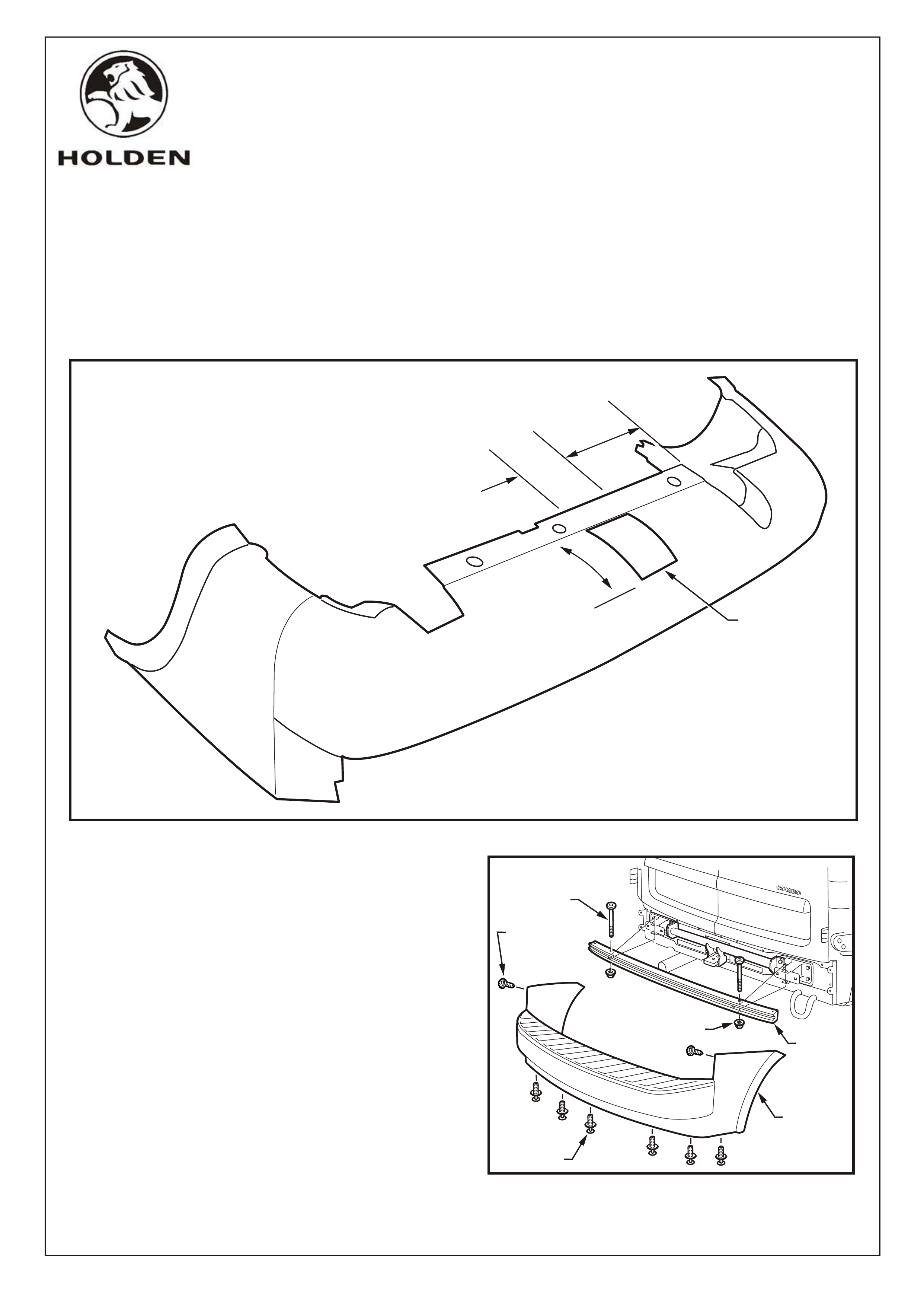
FIGURE 15
21. Reinstall the crash limiter. Torque M8 nuts to
specification.
NOTE: Ensure the trailer harness is installed before
reinstalling the bumper fascia.
Reinstall the bumper fascia.
Refer Figure 16.
120mm
260mm
140mm
CUTOUT
FIGURE 16
REAR
BUMPER
CRASH
LIMITER
T45 x 65MM TORX
HEAD BOLT
SCREW
2 PLACES
SCRIVET
6 PLACES
NUT
2 PLACES
REAR
BUMPER
FASCIA
FITTING INSTRUCTIONS: - continued.
19. Carefully mark the area of the bumper fascia to be cut out as indicated.
Refer Figure 15.
IMPORTANT: Re-check the measurements before cutting the bumper fascia.
20. Carefully cut out the marked section of the bumper fascia using a suitable saw.
NOTE: Take precautions to prevent damage to the bumper fascia.
COPYRIGHT
Page 8 of 8
HOLDEN SERVICE PARTS OPERATIONS
Reproduction in whole or part
prohibited without written approval
Division of HOLDEN Ltd Can 006 893 232
XC COMBO
1000kg TOWBAR PACKAGE (92145397)
PARTS LIST
PART NUMBER DESCRIPTION QUANTITY
TOWBAR ASSEMBLY 1
92145612 TOWBAR TONGUE 1
SUPPORT BRACKET - LHS 1
SUPPORT BRACKET - RHS 1
SPACER TUBE - 17.3 mm OD 2
SPACER TUBE - 22 mm OD 4
RUBBER HOSE SPACER 4
CARGO BRACKET 2
COACH BOLT 2
BOLT - M10 x 90 4
M10 NUT 6
HEX BOLT - M16 x 45 2
SPRING WASHER - M16 2
92077203 D-SHACKLE 1
ADR/USAGE LABEL 1
92146212 TRAILER HARNESS (INCLUDED) 1
FD1100 FITTING INSTRUCTIONS 1
FD1100
16SE02
G681
FITTING INSTRUCTIONS: - continued.
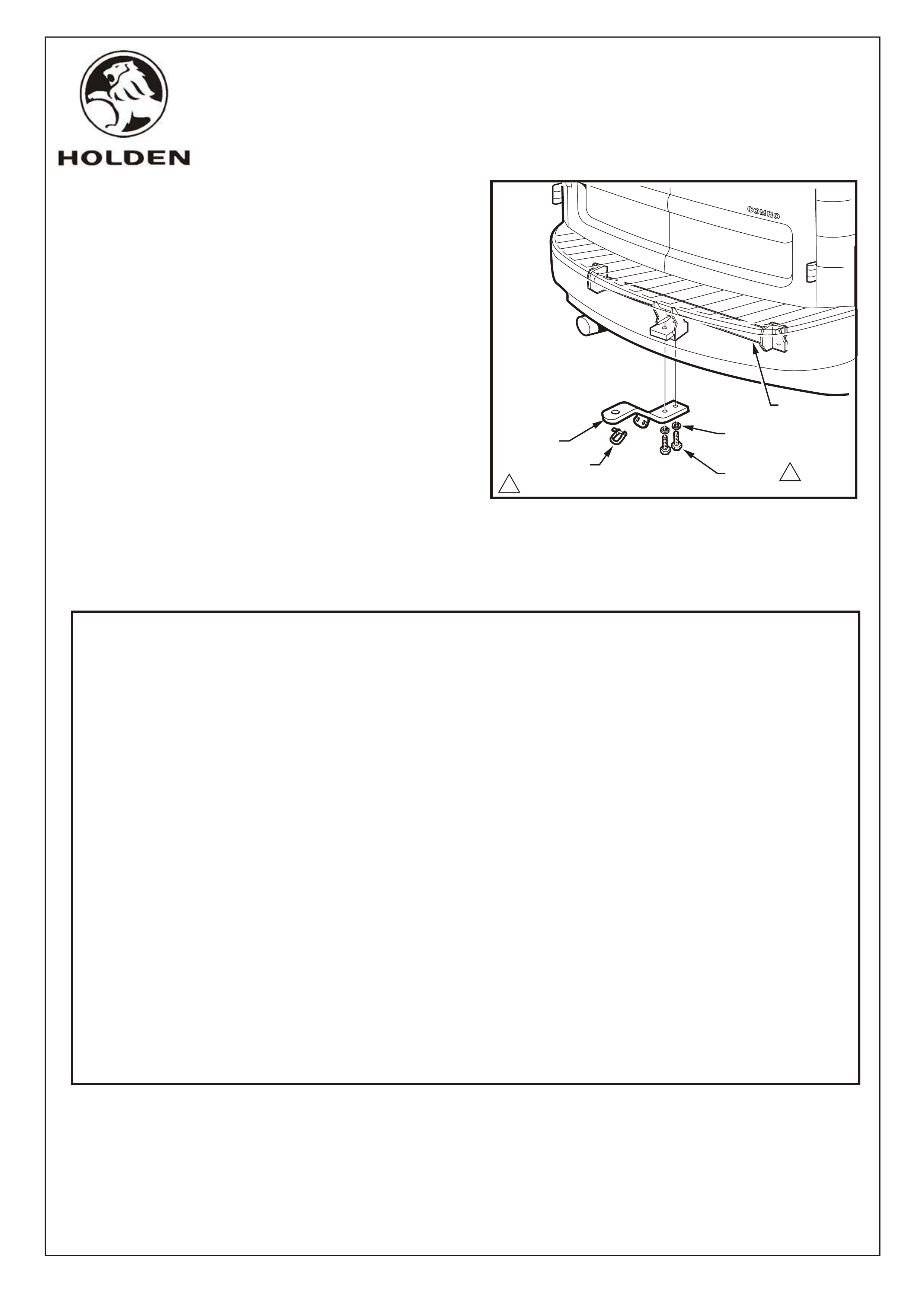
22. Fit the tongue to the towbar assembly using 2 M16 x 45
bolts and M16 spring washers. Refer Figure 17.
Torque to specifications.
23. Refit all removed parts ensuring fasteners are to
specified torques.
24. Place the fitting instructions in the vehicle glovebox.
FIGURE 17
180 - 90 Nm
TONGUE
TOW BAR
ASM.
D SHACKLE
M16 SPRING
WASHER
M16 BOLT 1