
Roof Page 9–1
Page 9–1
Section 9
Roof
ATTENTION
Before performing any Service Operation or other procedure described in this Section, refer to Section 2
Precautions, and Section 00 Warnings, Cautions and Notes in the MY 2004 VY Regular Cab and Crew Cab
Service Information for correct w orkshop practices with regard to safety and/or property damage.
The body structure of VY Regular Cab and
Crew Cab vehicles has been developed using
complex design and d evelopment techniques.
In addition to meeting all required standards,
the vehicle body is also a critical part of the
overall safety systems. It is therefore
imperative the repair procedures described in
this Supplement are adhered to during all
vehicle body repairs.
1 General Information ...............................................................................................................................2
1.1 Crew Cab Roof Components ................................................................................................................................ 2
2 Service Operations – Crew Cab............................................................................................................4
2.1 Roof Panel – Replace ............................................................................................................................................ 4
Remove................................................................................................................................................................... 4
Replace................................................................................................................................................................... 6
2.2 Roof Front Header Panel – Replace ..................................................................................................................... 9
2.3 Roof Bow Panel – Replace.................................................................................................................................. 10
2.4 Roof Rear Header Outer Panel – Replace.......................................................................................................... 11
Remove................................................................................................................................................................. 11
Replace................................................................................................................................................................. 11
2.5 Roof Rear Header Inner Panel – Replace........................................................................................................... 13
Remove................................................................................................................................................................. 13
Roof Page 9–2
Page 9–2
1 General Information
With the following exceptions, VY Regular Cab and Crew Cab roof information carries over from MY 2003 VY Series
vehicles.
Crew Cab:
• Roof components
• Roof panel
• Roof rear header inner and outer pane ls
The Roof structure fitted to VY Regular Cab vehicles carries over from MY 2003 VY Utility vehicles.
For information not contained within this Section, refer to Section 9 Roof in the MY 2003 VY and V2 Series Service
Information Supplement, Body Structure Repair. Removal of trim and bolt-on components is not covered. Reference
must be made to the appropriate Sections in the MY 2004 Regular Cab and Crew Cab Service Information.
The roof panel is both spot welded and glued in place with structural adhesive. Heating or other normal means cannot
soften this adhesive and the panel can o nly be removed by cutting and/or grinding.
NOTE
• When repairing the roof of the vehicle, care
must be taken to ensure the structure is
returned to its original production
configuration.
• It is imperative that the correct body
adhesives, sealers, deadeners and cavity
waxes are used when repairing the body
structure of VY Crew Cab vehicles. Refer to
Section 3B, 5 Body Sealing, Adhesives and
Deadeners and 6 Cavity Wax for details of the
correct materials and their commercially
available equivalents.
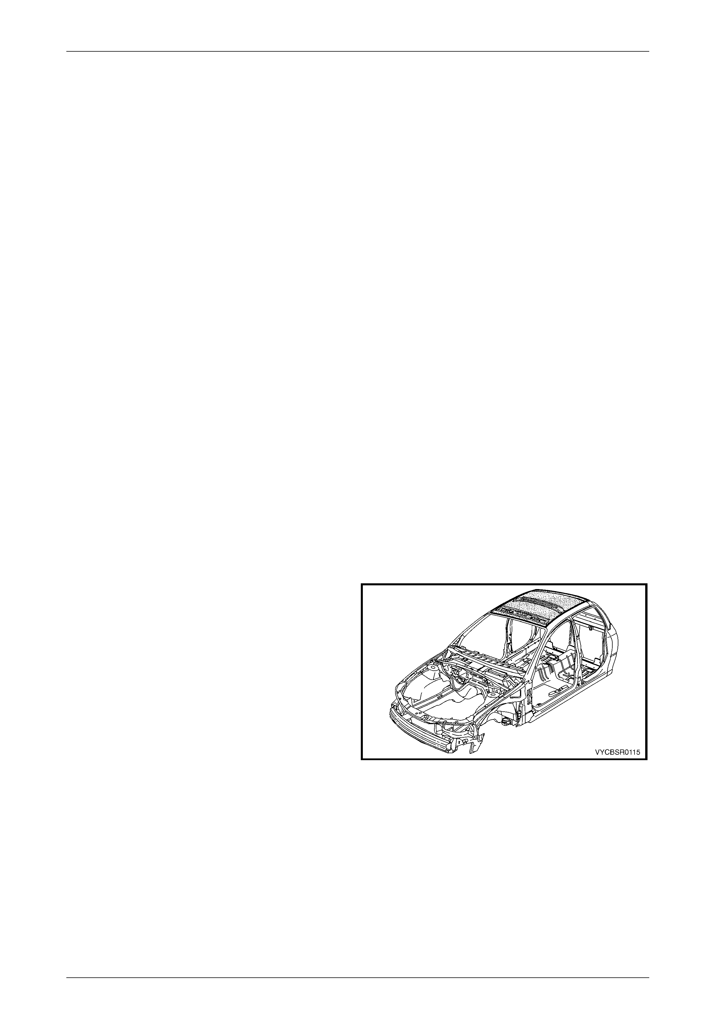
1.1 Crew Cab Roof Components
The shaded components in Figure 9 – 1 are those dealt with
in this Section.
The components and assemblies shown in Figure 9 – 2 are
the parts serviced for VY Crew Cab vehicles which form the
basis of the repair procedures in this Section. For a detailed
view of the body components, refer to
Section 3B Body Construction, Crew Cab.
NOTE
Always refer to an Authorised Dealer for spare
parts availability configurations.
Figure 9 – 1

Roof Page 9–3
Page 9–3
Figure 9 – 2
Legend
1 Roof Front Header Panel
2 Roof Panel
3 Roof Bow Panel
4 Roof Rear Header Inner Panel
5 Roof Rear Header Outer Panel
Roof Page 9–4
Page 9–4
2 Service Operations – Crew Cab
2.1 Roof Panel – Replace
Remove
1 Remove the adjacent trim and components as described in the appropriate Section of the MY 2004 VY Regular
Cab and Crew Cab Service Information.
2 Remove the adjacent bolt-on panels and components as described in the appropriate Section of the MY 2004 VY
Regular Cab and Crew Cab S ervice Information.
3 Remove the windshield and rear window, refer to Section 1A6 Stationary Windows in the MY 2004 VY Regular Cab
and Crew Cab Service Information.
4 Remove other adjacent pane ls as required, refer to the relevant Section in this Supplement.
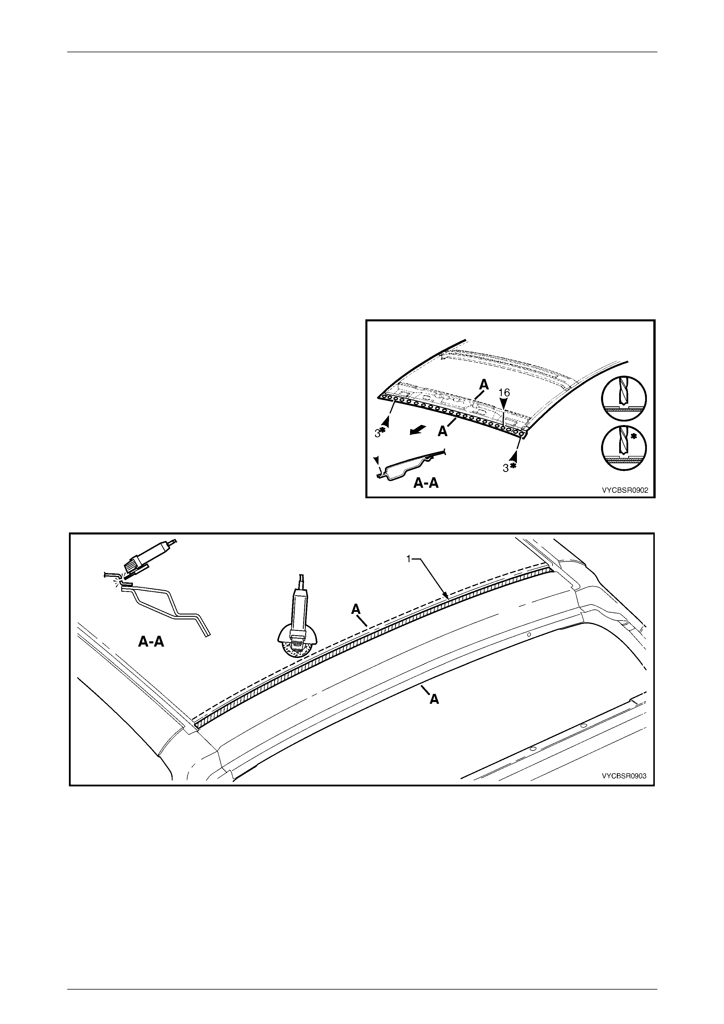
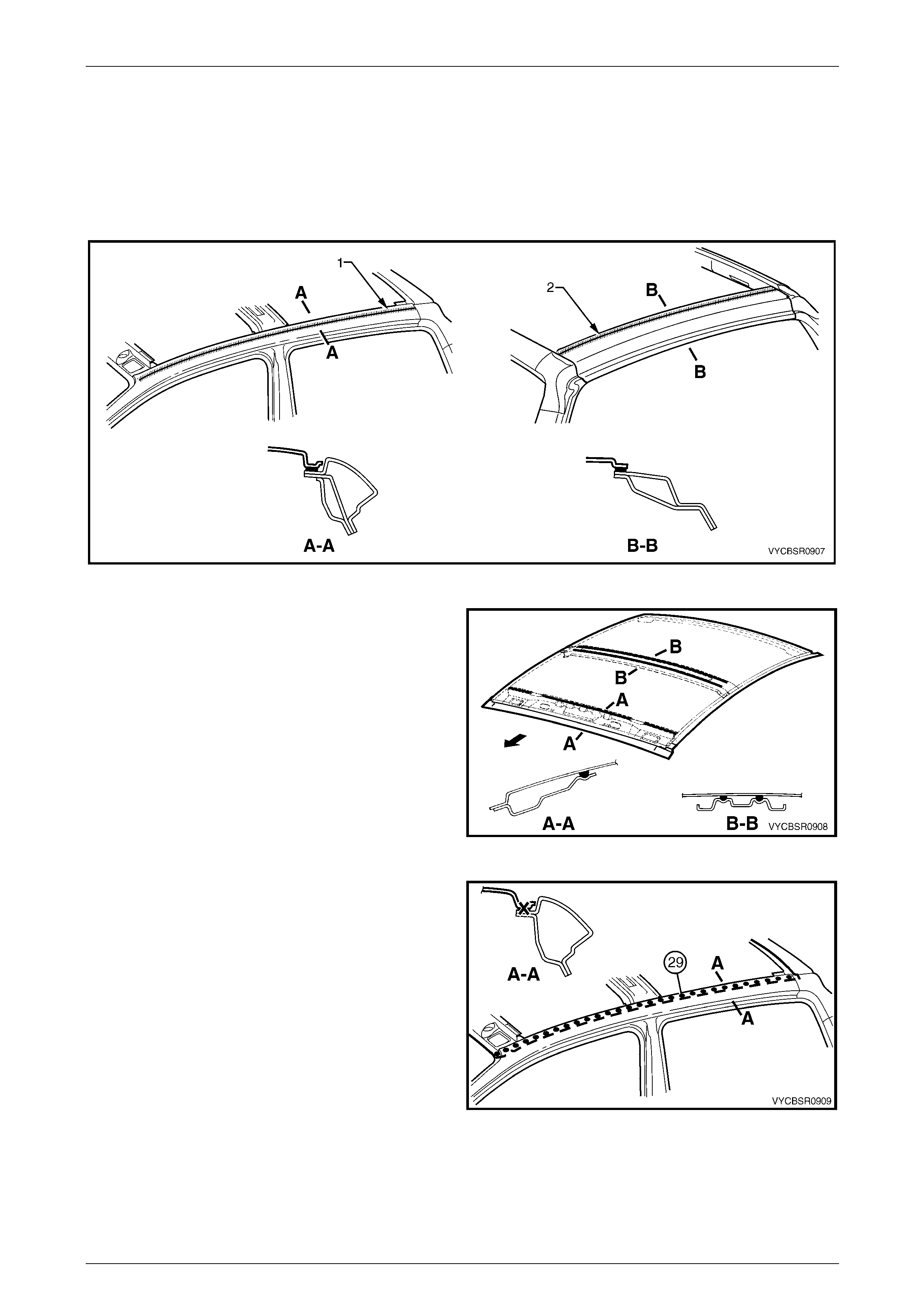
5 Spot cut the welds attaching the roof panel to the roof
front header panel.
6 Using a cutting tool such as an air chisel or a ngle
grinder, cut through the roof panel alo ng the rear of
the roof, refer to Figure 9 – 4.
NOTE
As the roof panel is attached with structural
adhesive (1) to the roof rear head er outer panel,
it cannot be removed by simply spot cutting the
welds.
Figure 9 – 3
Figure 9 – 4
Roof Page 9–5
Page 9–5
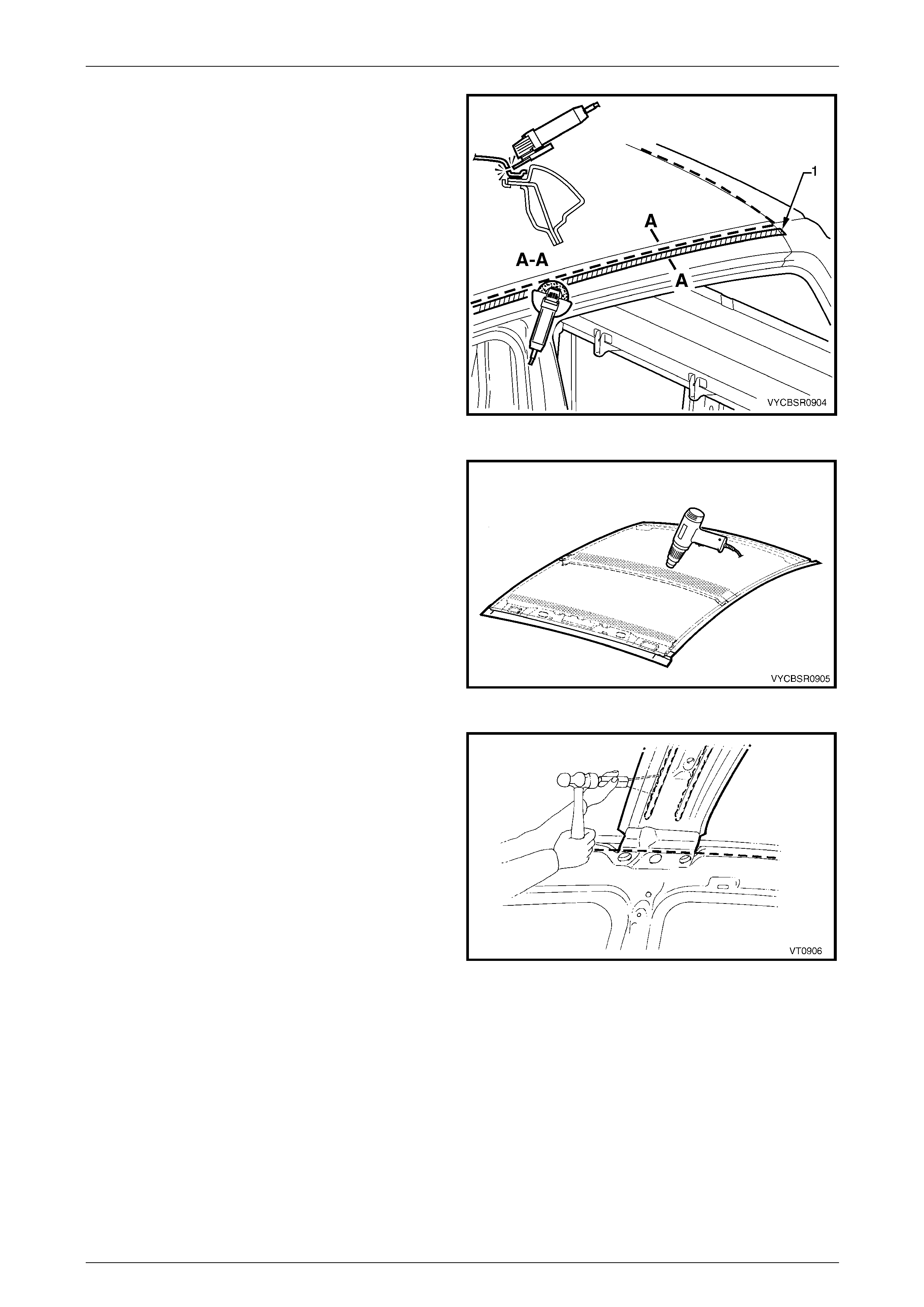
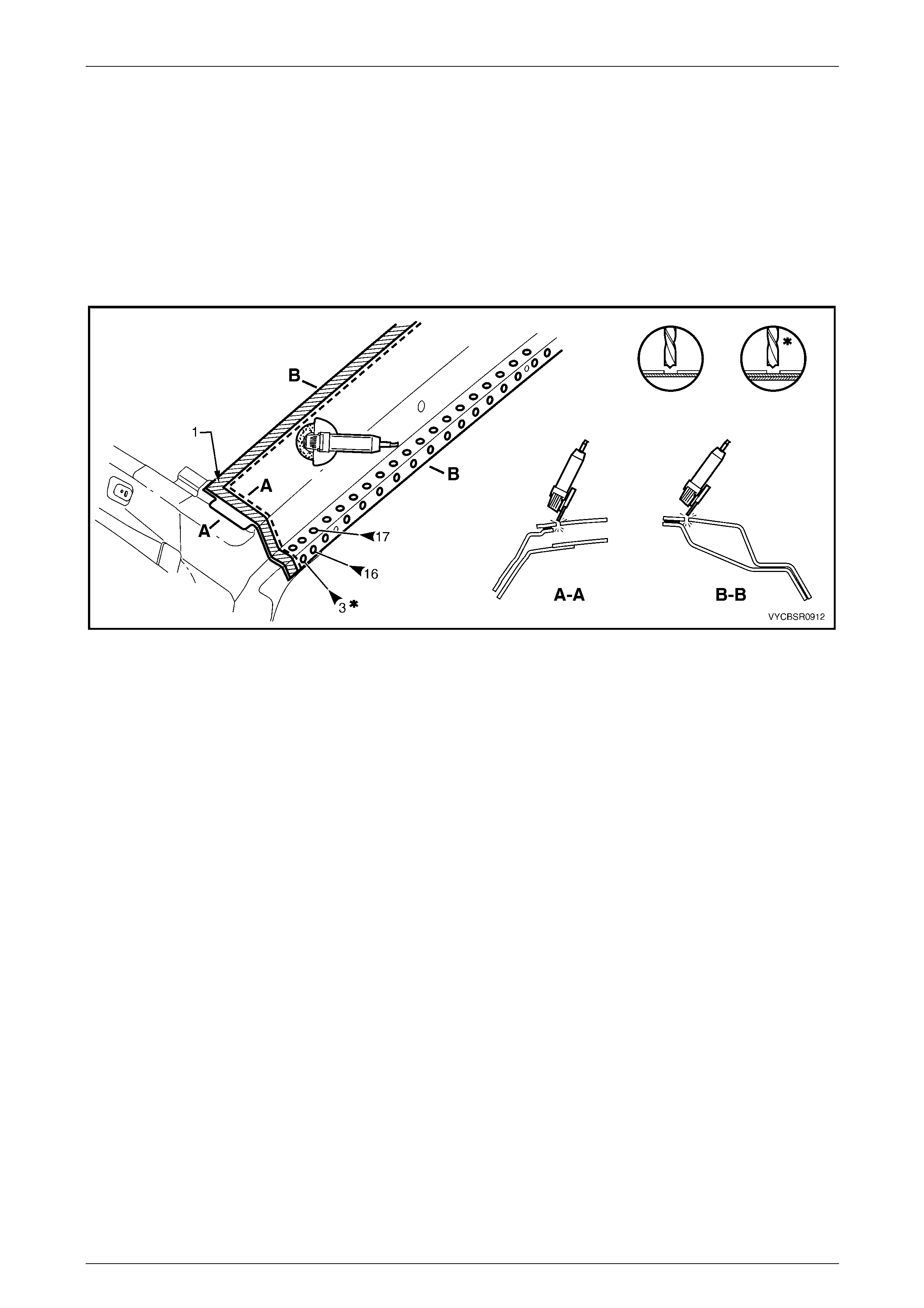
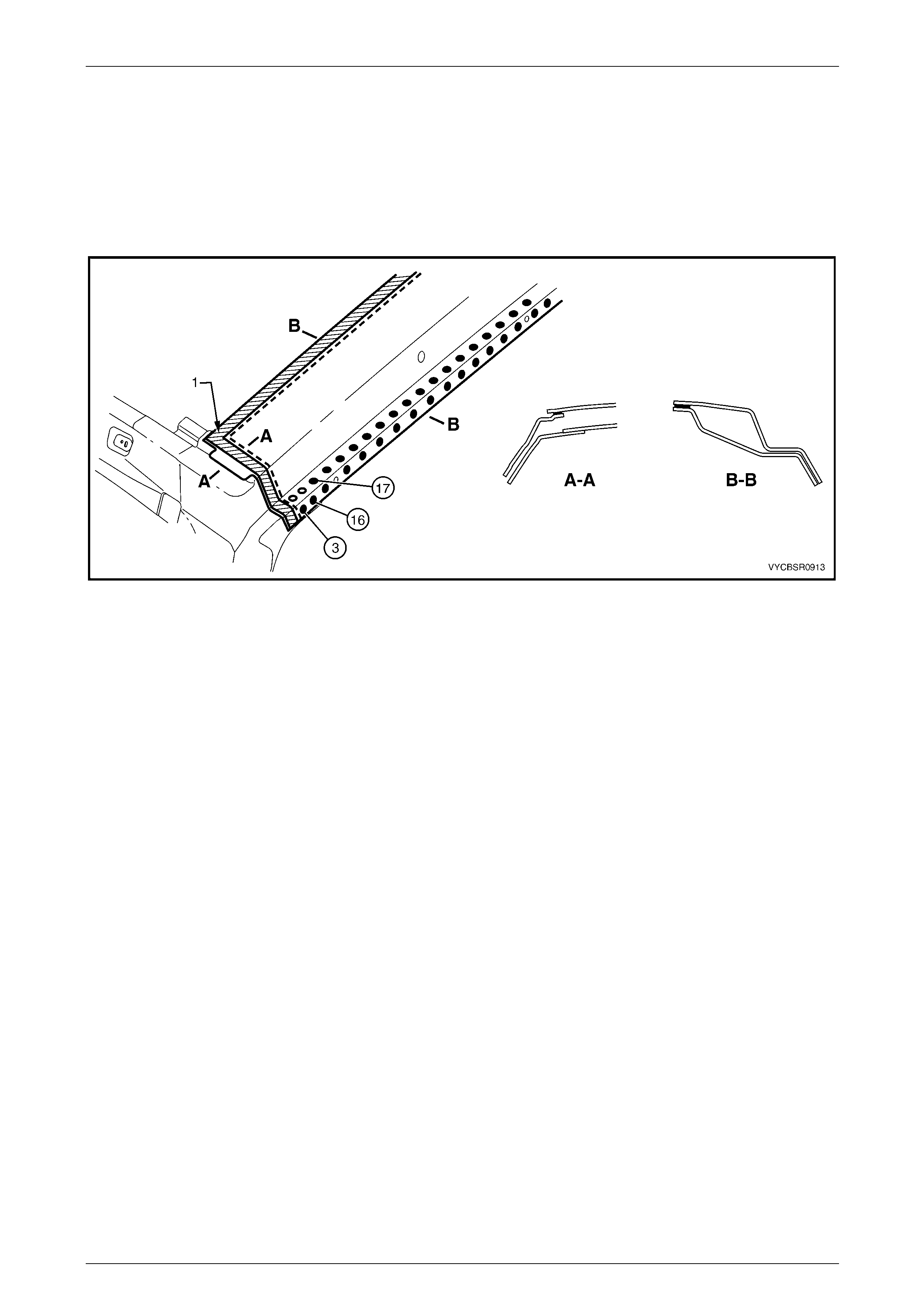
7 Using a cutting tool such as an air chisel or a ngle
grinder, cut through the roof panel along the side of
the roof channel.
NOTE
As the roof panel is attached with structural
adhesive (1) to the door opening frame
assembly, it cannot be removed by simply spot
cutting the welds.
If the roof front header panel, roof bow panel and
roof rear header inner a nd ou ter pa nels ar e t o b e
retained, take care not to cut them off with the
roof panel. Alternatively, if on e or more are to be
replaced, it is easier to cut off those being
replaced along with the roof panel.
Figure 9 – 5
8 Use a heat gun to soften the Anti-flutter adhesive
between the roof front header panel a nd roof bow
panel by heating the areas sh own.
Figure 9 – 6
9 Cut through the softened adhesive between the roof
panel and roof front header panel, roof bow panel and
roof rear panel using a suitable tool.
10 Remove the roof panel from the vehicle.
Figure 9 – 7
Roof Page 9–6
Page 9–6
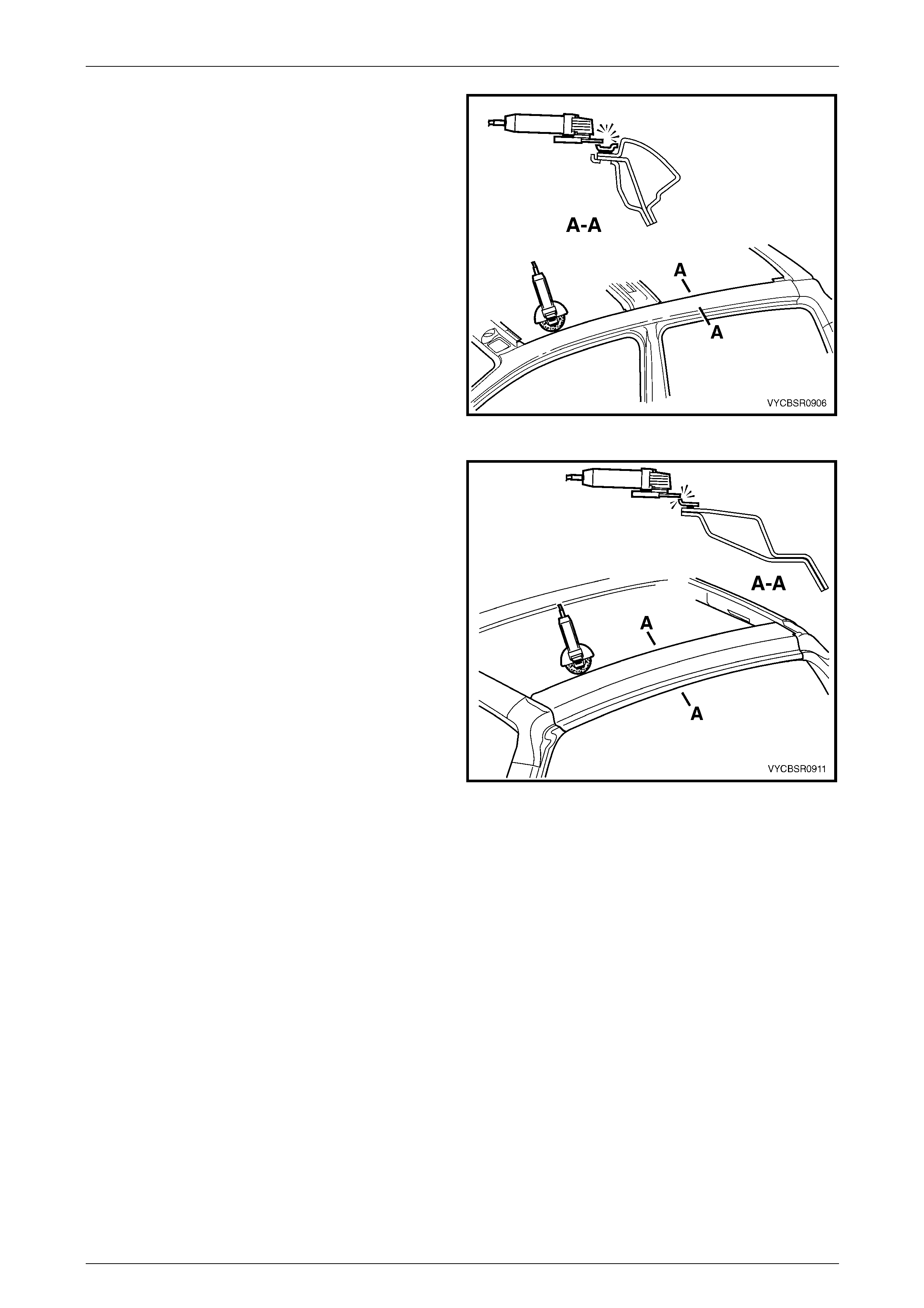
11 Using an angle grind er, air chi s el or other suitable tool,
remove the remaining strip of roof panel from the door
opening frame assembly, along with the adhesive
beneath the strip.
Figure 9 – 8
12 Using an angle grind er, air chi s el or other suitable tool,
remove the remaining strip of roof panel from the rear
roof header outer panel, along with the adhesive
beneath the strip.
13 Repair any damage to adjacent parts.
14 Check and rectify the alignme nt of the bod y as
required, refer to Section 3B, 3 Body Dimensions.
Figure 9 – 9
Replace
NOTE
When welding a relatively flat panel such as the
roof panel, due care must be taken to minimise
the heat absorbed by the pan el, which could lead
to panel distortion.
NOTE
Spot welding is the preferred method for
attaching of panels and should be used whenever
possible. Where the spot welding equipment will
not access the required weld position, a plug
weld should be performed.
The same number and position of spot welds (or
plug welds) should be used when replacing the
panel, as was used during manufacture, in order
to maintain the original structural strength of the
vehicle.
Roof Page 9–7
Page 9–7
1 Clean the remaining Anti-flutter adhesive fro m the surfaces of the roof front header panel and, roof bo w panel.
2 Prepare the mating surface areas for welding. Dress the channel flange area, the roof fro nt head er panel, roof bow
panel and roof rear inner and outer panels as required so they are flat and free from imperfections.
3 As required, mark the new panel with drilling locations in preparation for pl ug welding. Drill holes as requ ired.
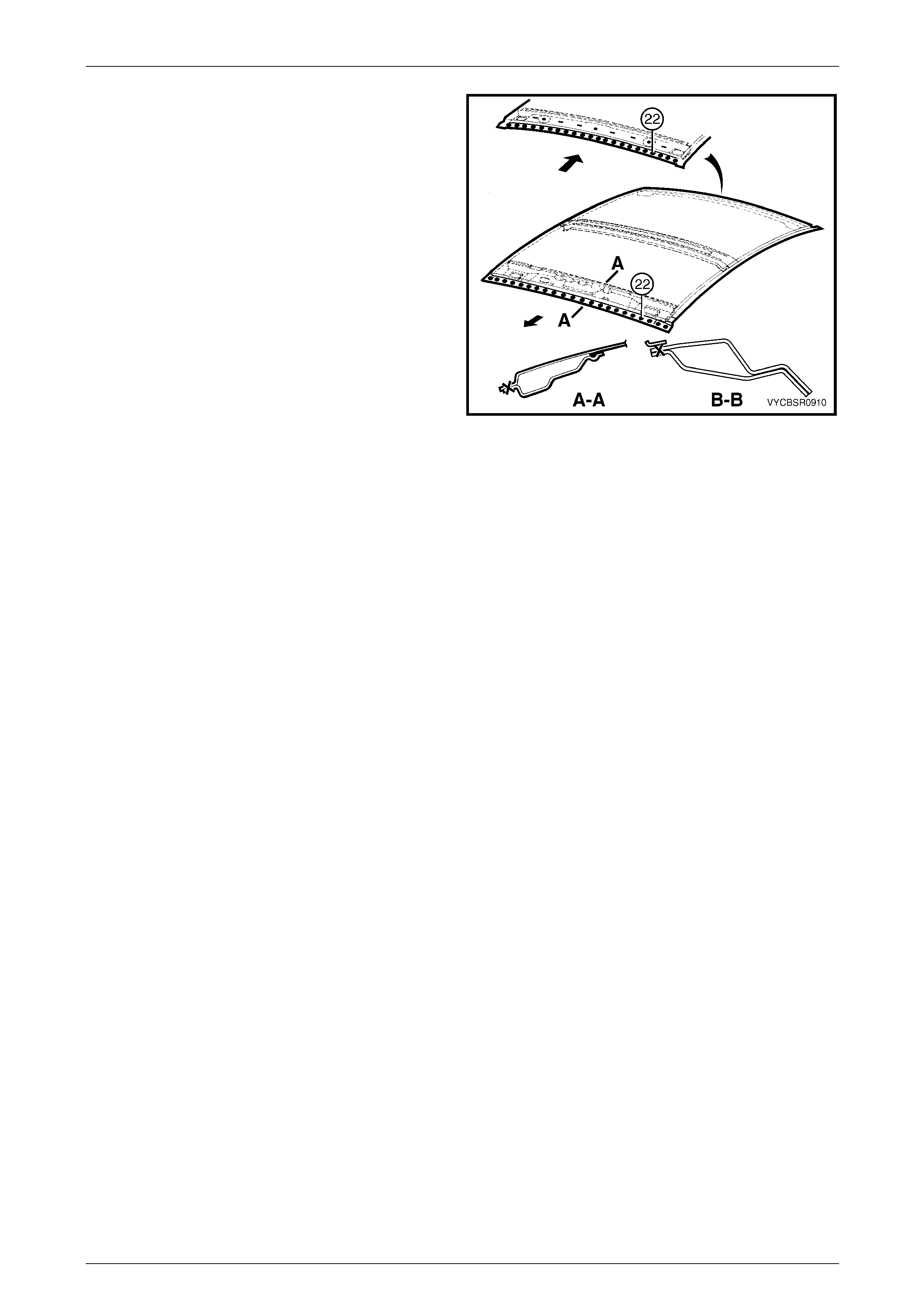
4 Apply Structural Adhesive (Item 6), refer to Section 3B, 5 Body Sealing, Adhesives & Deadeners, to the door
opening frame assembly flange (1) and re ar roof header outer panel flange (2), refer to Figure 9 – 10.
Figure 9 – 10
5 Apply a bead of Anti-flutter Adhesiv e (Item 5) to the full
length of the groove in the roof front header panel.
Refer to Section 3B, 5 Body Sealing, Adhesives &
Deadeners.
6 Apply two full length bea ds of Anti-flutter adhesive to
the grooves in the roof bow panel, refer to Section 3B,
5 Body Sealing, Adhesives & Dea deners.
7 Position the roof panel on the vehicle and clamp in
place.
Figure 9 – 11
8 Spot or plug weld the roof panel to the door opening
frame on both sides of the vehicle.
NOTE
In some cases it may be advantageous to begin
welding from the middle of the run and weld
alternatively to the front and rear. This may
reduce panel distortion.
Figure 9 – 12
Roof Page 9–8
Page 9–8
9 Spot or plug weld the roof panel to the roof front
header panel and the roof rear header inner and outer
panels.
10 Refinish and paint panels and other components as
required. Refer to Section 3, 1.3 Paint Refinishing in
the MY2003 VY and V2 Servi ce Information
Supplement, Body Structure Repair.
11 Apply Joint Sealer (Item 3) as required. Refer to
Section 3B, 5 Body Sealing, Adhesives & Deadeners.
12 Apply Cavity Wax (Item 8) as required to the inside of
any box sections or areas inaccessible to paint, refer
to Section 3B, 6 Cavity Wax.
13 Replace the windshield and rear window, refer to
Section 1A6 Stationary Glass in the MY 2004 VY
Regular Cab and Crew Cab S ervice Information.
14 Install the remaining components as described in the
appropriate Section of the MY 2004 VY Regu lar Cab
and Crew Cab Service Information. Figure 9 – 13
Roof Page 9–9
Page 9–9
2.2 Roof Front Header Panel – Replace
Following removal of the roof panel, as required spot cut the welds attaching the roof front header panel as shown in the
following diagram.
When installing a roof front header p an el, eit her spot weld the part to the vehicle or mark and drill the new part with holes
in preparation for plug welding. The number of spot or plug welds must match the number shown in the appropriate
diagram.
Before fitting the part, prepare the mating surfaces and treat with Weld Through Primer (Item 1) as required, refer to
Section 3B, 5 Body Sealing, Adhesives & Deadeners.
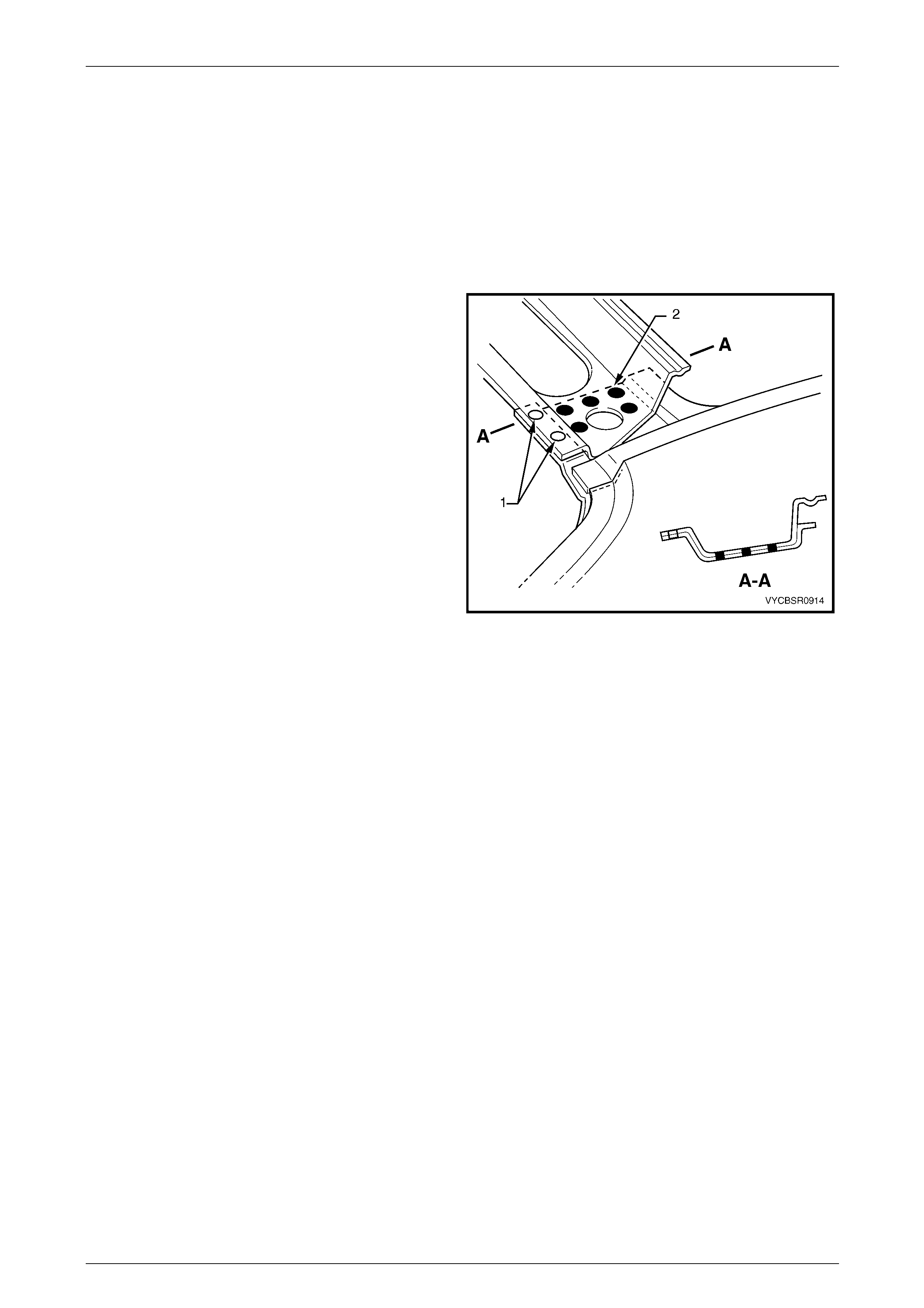
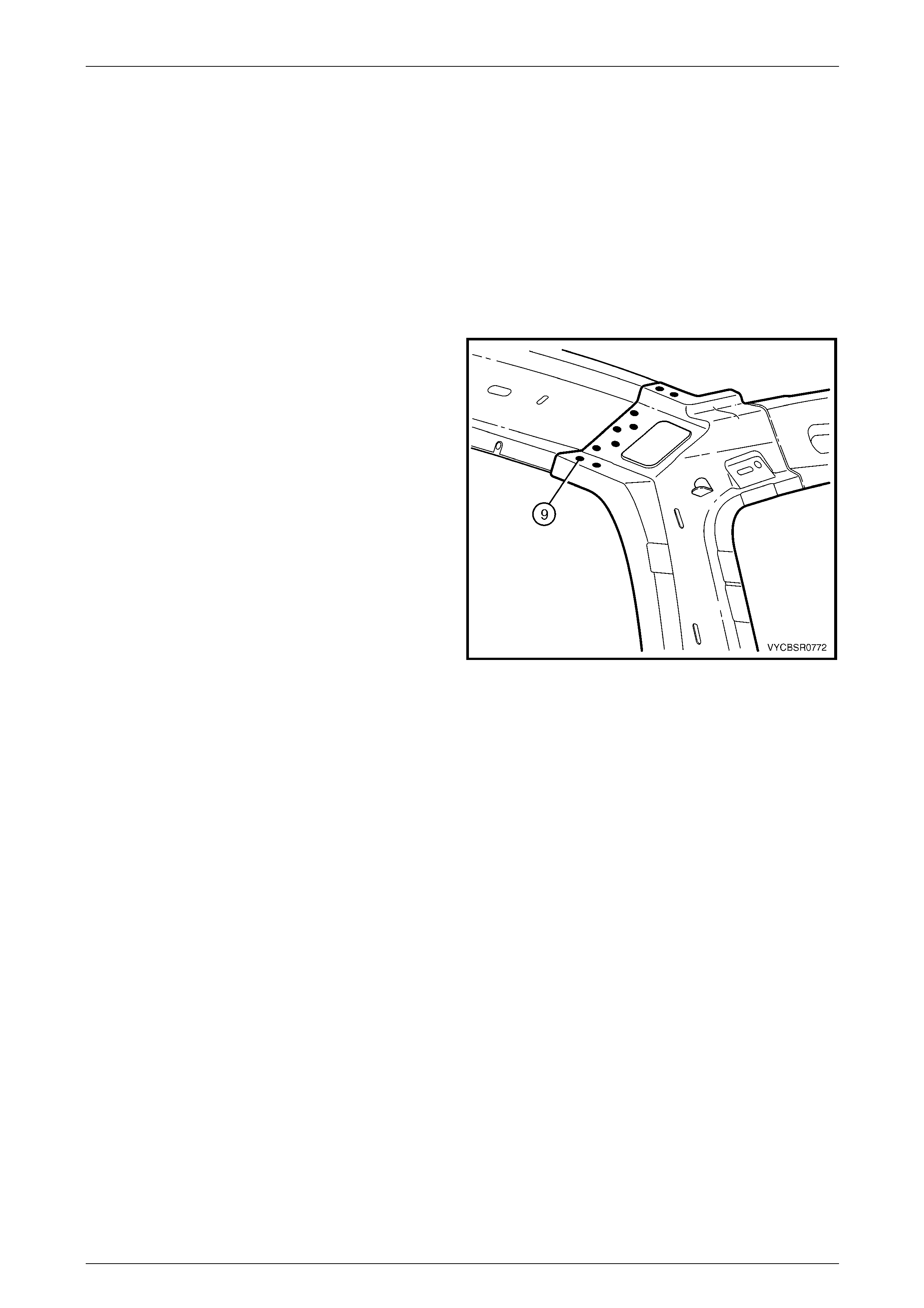
1 The two spot welds (1) are removed with the roof
panel.
2 Remove the five spot welds (2) from each side of the
vehicle to remove the roof front header panel.
3 Remove the roof front header panel from the vehicle
and repair any dama ge to adjacent parts as required.
4 Check and rectify the alignme nt of the bod y as
required, refer to Section 3B, 3 Body Dimensions.
Figure 9 – 14
Roof Page 9–10
Page 9–10
2.3 Roof Bow Panel – Replace
Following removal of the roof panel, as required spot cut the welds attaching the roof bow panels as sh own in the
following diagrams.
When installing a roof bow panel, either spot weld the part to the vehicle or mark and drill the new part with holes in
preparation for plug welding. The number of spot or plug welds must match the number sho wn in the appropriate
diagram.
Before fitting the part, prepare the mating surfaces and treat with Weld Through Primer (Item 1) as required, refer to
Section 3B, 5 Body Sealing, Adhesives & Deadeners.
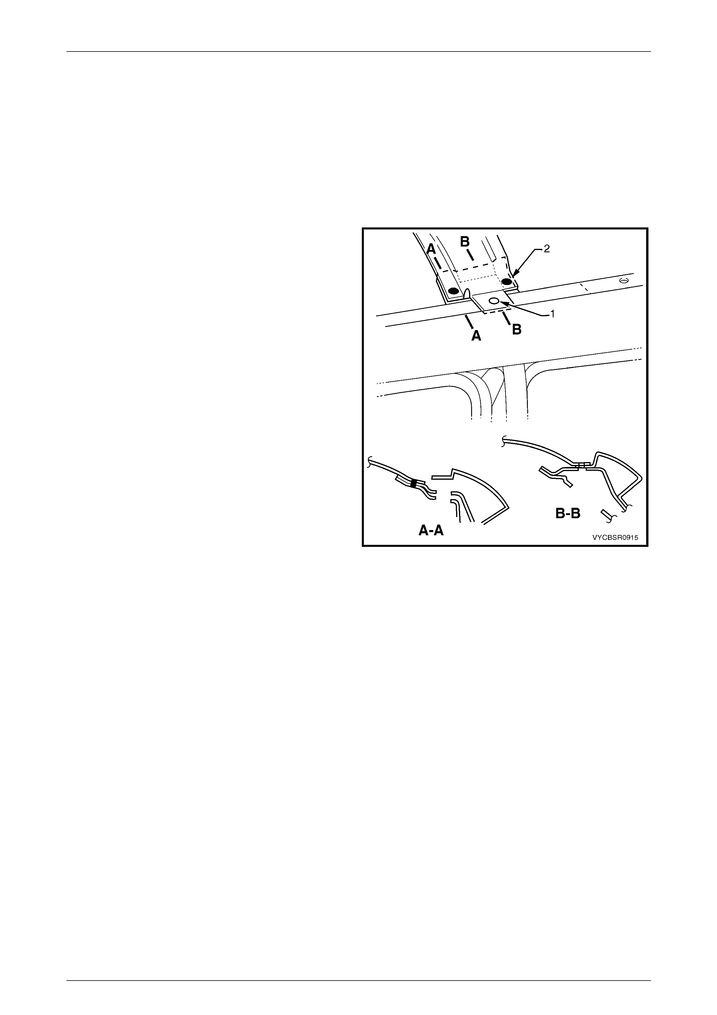
1 The spot weld (1) is removed with the roof panel.
2 Remove the two spot welds (2) from each side of the
vehicle to remove the roof bow panel.
3 Remove the roof bow panel from the vehic le and
repair any damage to adjacent parts as required.
4 Check and rectify the alignme nt of the bod y as
required, refer to Section 3B, 3 Body Dimensions.
Figure 9 – 15
Roof Page 9–11
Page 9–11
2.4 Roof Rear Header Outer Panel – Replace
Remove
1 Remove the adjacent bolt-on panels a nd components as described in the appropri ate Se ction of the MY 2004
Regular Cab and Crew Cab S ervice Information.
2 Remove the roof panel, refer to 2.1 Roof Panel – Replace.
3 Using a cutting tool such as an air chisel or a ngle grinder, cut through the roof rear header outer panel in from the
forward flange and in from each end (1), refer to Figure 9 – 16.
Figure 9 – 16
4 Spot cut the welds, three places, attaching the roof rear header outer panel to the roof rear head er inner panel and
quarter panel inner assembly. Repeat for the opposite side of the vehicle.
5 Spot cut the welds attaching the roof rear header outer panel to the roof re ar header inner panel.
6 Remove the roof rear header outer pane l from the vehicle.
7 Using a cutting tool such as an air chisel or a ngle grinder, remove the remaining strip of roof rear header outer
panel, along with the adhesive beneath the strip.
8 Repair any damage to adjacent parts as required.
9 Check and rectify the alignme nt of the body as required, refer to Section 3B, 3 Body Dimensions.
Replace
NOTE
Spot welding is the preferred method for
attaching of panels and should be used whenever
possible. Where the spot welding equipment will
not access the required weld position, a plug
weld should be performed.
The same number and position of spot welds (or
plug welds) should be used when replacing the
panel, as was used during manufacture, in order
to maintain the original structural strength of the
vehicle.
Roof Page 9–12
Page 9–12
1 Prepare the mating surfaces and treat with Weld Through Primer (Item 1) as required, refer to Section 3 B,
5 Body Sealing, Adhesives & Dea deners.
2 Apply Structural Adhesive (1, Item 6), refer to Section 3B, 5 Body Sealing, Adhesives and Deadeners, refer to
Figure 9 – 17.
3 Clamp the new panel in position on the vehicle.
4 Plug or spot weld on each side of the vehicle , attaching the roof rear header outer panel to the quarter panel inn er
assembly and roof rear heade r inner panel.
Figure 9 – 17
5 Refinish and paint panels and other components as required. Refer to Section 3, 1.3 Paint Refinishing in the
MY2003 VY and V2 Service Information Supplement, Body Structure Repair.
6 Apply Joint Sealer (Item 3) as required, refer to Section 3B, 5 Body Sealing, Adhesives and Deadeners.
7 Apply Cavity Wax (Item 8) as required to the inside of any box sections or areas inaccessible to paint, refer to
Section 3B, 6 Cavity Wax.
8 Reinstall the remaining com ponents as described in the appropriate Section in the MY 2004 VY Regular Cab and
Crew Cab Service Information.
Roof Page 9–13
Page 9–13
2.5 Roof Rear Header Inner Panel – Replace
Remove
Following removal of the roof panel, as required spot cut the welds attaching the roof rear header inner panel as shown
in the following diagrams.
When installing a roof rear header inner panel, either spot weld the part to the vehicle or mark and drill the new part with
holes in preparation for plug welding. The number of spot or plug welds must match the number shown in the appropriate
diagram.
Before fitting the part, prepare the mating surfaces and treat with Weld Through Primer (Item 1) as required, refer to
Section 3B, 5 Body Sealing, Adhesives & Deadeners.
1 Spot cut the welds from each side of the vehicle
attaching the roof rear heade r inner panel.
2 Remove the roof rear header inner pan el from the
vehicle and repair any damag e to adjacent parts as
required.
3 Check and rectify the alignme nt of the bod y as
required, refer to Section 3B, 3 Body Dimensions.
Figure 9 – 18