
Rear Tray Body Assembly, Crew Cab Page 11–1
Page 11–1
Section 11
Rear Tray Body Assembly, Crew Cab
ATTENTION
Before performing any Service Operation or other procedure described in this Section, refer to Section 2
Precautions, and Section 00 Warnings, Cautions and Notes in the MY 2004 VY Regular Cab and Crew Cab
Service Information for correct wo rkshop practices with regard to safety and/or property damage.
The body structure of VY Regular Cab and
Crew Cab vehicles has been developed using
complex design and d evelopment techniques.
In addition to meeting all required standards,
the vehicle body is also a critical part of the
overall safety systems. It is therefore
imperative the repair procedures described in
this Supplement are adhered to during all
vehicle body repairs.
1 General Information ...............................................................................................................................3
1.1 Body Rear Components........................................................................................................................................ 3
2 Service Operations.................................................................................................................................6
2.1 Rear End Lower Panel – Replace ......................................................................................................................... 6
Remove................................................................................................................................................................... 6
Replace................................................................................................................................................................... 7
2.2 Endgate Hinge Reinforcement – Replace.......................................................................................................... 10
Remove................................................................................................................................................................. 10
Replace................................................................................................................................................................. 10
2.3 Rear End Panel – Replace................................................................................................................................... 12
Remove................................................................................................................................................................. 12
Replace................................................................................................................................................................. 14
2.4 Rear Quarter Panel – Replace............................................................................................................................. 16
Remove................................................................................................................................................................. 16
Replace................................................................................................................................................................. 18
2.5 Rear Quarter Closing Panel – Replace............................................................................................................... 21
Remove................................................................................................................................................................. 21
Replace................................................................................................................................................................. 21
2.6 Quarter Panel Extension – Replace.................................................................................................................... 23
Remove................................................................................................................................................................. 23
Replace................................................................................................................................................................. 25
2.7 Quarter Panel Front Gusset – Replace .............................................................................................................. 27
Remove................................................................................................................................................................. 27
Replace................................................................................................................................................................. 28
2.8 Quarter Inner Lower Rear Extension – Replace................................................................................................ 29
Remove................................................................................................................................................................. 29
Replace................................................................................................................................................................. 30
2.9 Quarter Panel Rear Brace – Replace.................................................................................................................. 31
Remove................................................................................................................................................................. 31
Replace................................................................................................................................................................. 32

Rear Tray Body Assembly, Crew Cab Page 11–2
Page 11–2
2.10 Quarter Lower Rear Panel – Replace ................................................................................................................. 33
Remove................................................................................................................................................................. 33
Replace................................................................................................................................................................. 34
2.11 Inner Side Panel – Replace ................................................................................................................................. 35
Remove................................................................................................................................................................. 35
Replace................................................................................................................................................................. 37
2.12 Inner Side Panel Extension Assembly – Replace ............................................................................................. 40
Remove................................................................................................................................................................. 40
Replace................................................................................................................................................................. 40
2.13 Load Floor Panel Front Extension – Replace.................................................................................................... 42
Remove................................................................................................................................................................. 42
Replace................................................................................................................................................................. 43
2.14 Rear Wheelhouse Inner Panel – Replace........................................................................................................... 44
Left-hand .............................................................................................................................................................. 44
Remove............................................................................................................................................................ 44
Replace............................................................................................................................................................ 46
Right-hand............................................................................................................................................................ 47
Remove............................................................................................................................................................ 47
Replace............................................................................................................................................................ 49
2.15 Front End Panel Sill Assembly – Replace ......................................................................................................... 51
Remove................................................................................................................................................................. 51
Replace................................................................................................................................................................. 52
2.16 Front End Panel – Replace.................................................................................................................................. 53
Remove................................................................................................................................................................. 53
Replace................................................................................................................................................................. 54
2.17 Load Floor Panel Rear Support – Replace ........................................................................................................ 55
Remove................................................................................................................................................................. 55
Replace................................................................................................................................................................. 56
2.18 Load Floor Panel Locator Guide – Replace....................................................................................................... 57
Remove................................................................................................................................................................. 57
Replace................................................................................................................................................................. 58
2.19 Load Floor Panel Front Support – Replace ....................................................................................................... 59
Remove................................................................................................................................................................. 59
Replace................................................................................................................................................................. 60
2.20 Load Floor Panel Locator – Replace.................................................................................................................. 61
Remove................................................................................................................................................................. 61
Replace................................................................................................................................................................. 62
2.21 Load Floor Panel Side Support – Replace......................................................................................................... 63
Remove................................................................................................................................................................. 63
Replace................................................................................................................................................................. 64
2.22 Load Floor Panel Support – Replace ................................................................................................................. 65
Remove................................................................................................................................................................. 65
Replace................................................................................................................................................................. 66
2.23 Front End Panel Locator – Replace.................................................................................................................... 67
Remove................................................................................................................................................................. 67
Replace................................................................................................................................................................. 68
2.24 Load Floor Panel – Replace................................................................................................................................ 69
Remove................................................................................................................................................................. 69
Replace................................................................................................................................................................. 72
2.25 Load Floor Front Extension – Replace .............................................................................................................. 76
Remove................................................................................................................................................................. 76
Replace................................................................................................................................................................. 77
3 Underfloor Component Location Dimensions ..................................................................................78
Rear Tray Body Assembly, Crew Cab Page 11–3
Page 11–3
1 General Information
This Section describes replacement procedures for the rear tray body assembly components of the MY 2004 VY Crew
Cab body structure. Removal of bolt-on and mechanical components is not covered. Reference must be made to the
appropriate Sections in the MY 2004 VY Regular Cab and Crew Cab Service Information.
When replacing the rear quarter panel for AWD Crew Cab vehicles, ensur e to order the correct part with holes for the
rear wheelhouse opening flare.
NOTE
• When repairing the rear tray body assembly,
care must be taken to ensure the structure is
returned to its original production
configuration.
• It is imperative that the correct body
adhesives, sealers, deadeners and cavity
waxes are used when repairing the body
structure of MY 2004 VY Regular Cab and
Crew Cab vehicles. Refer to 5 Body Sealing,
Adhesives & Deadeners and 6 Cavity Wax in
Section 3B for details of the correct materials
and their commercially available equivalents.
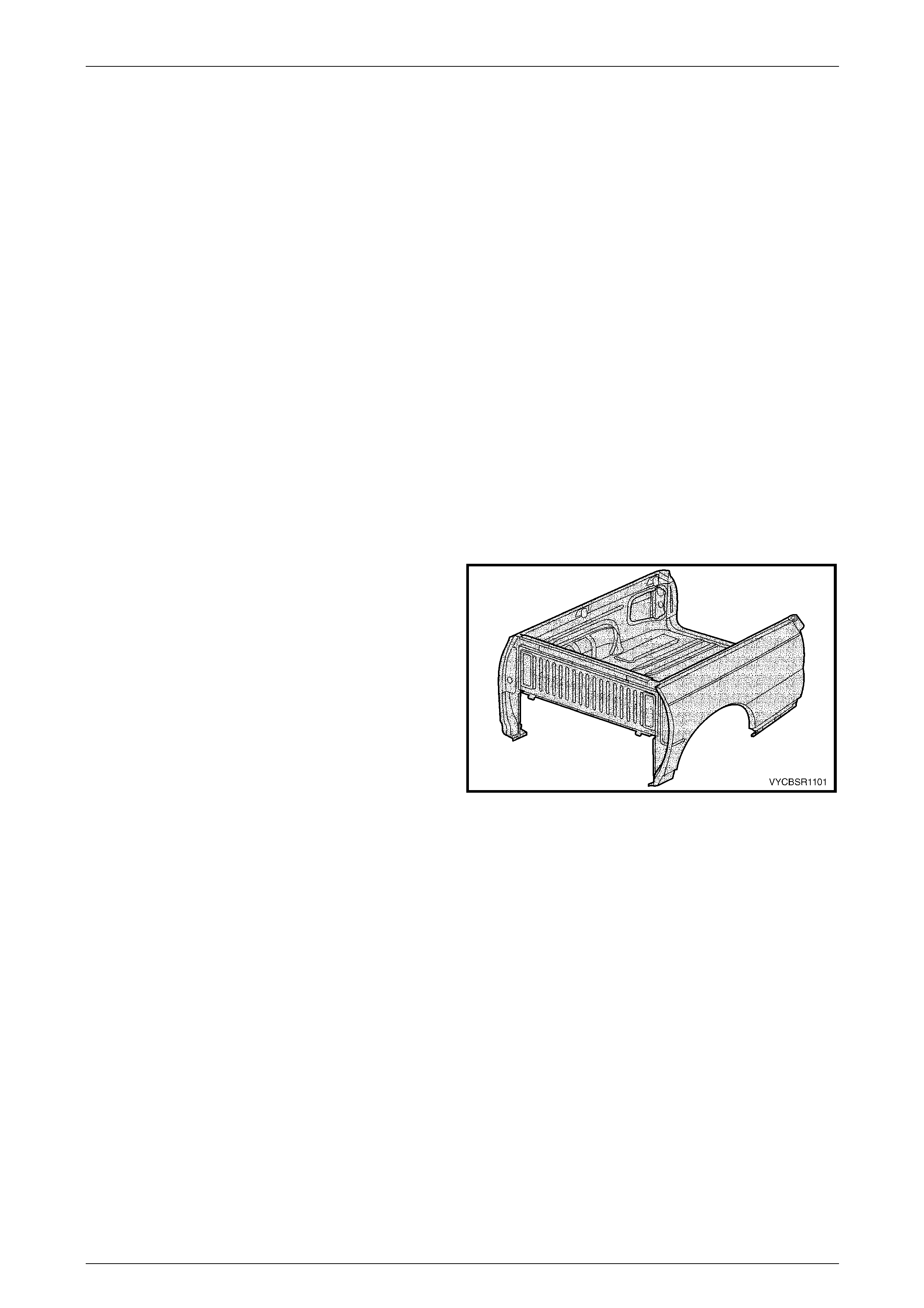
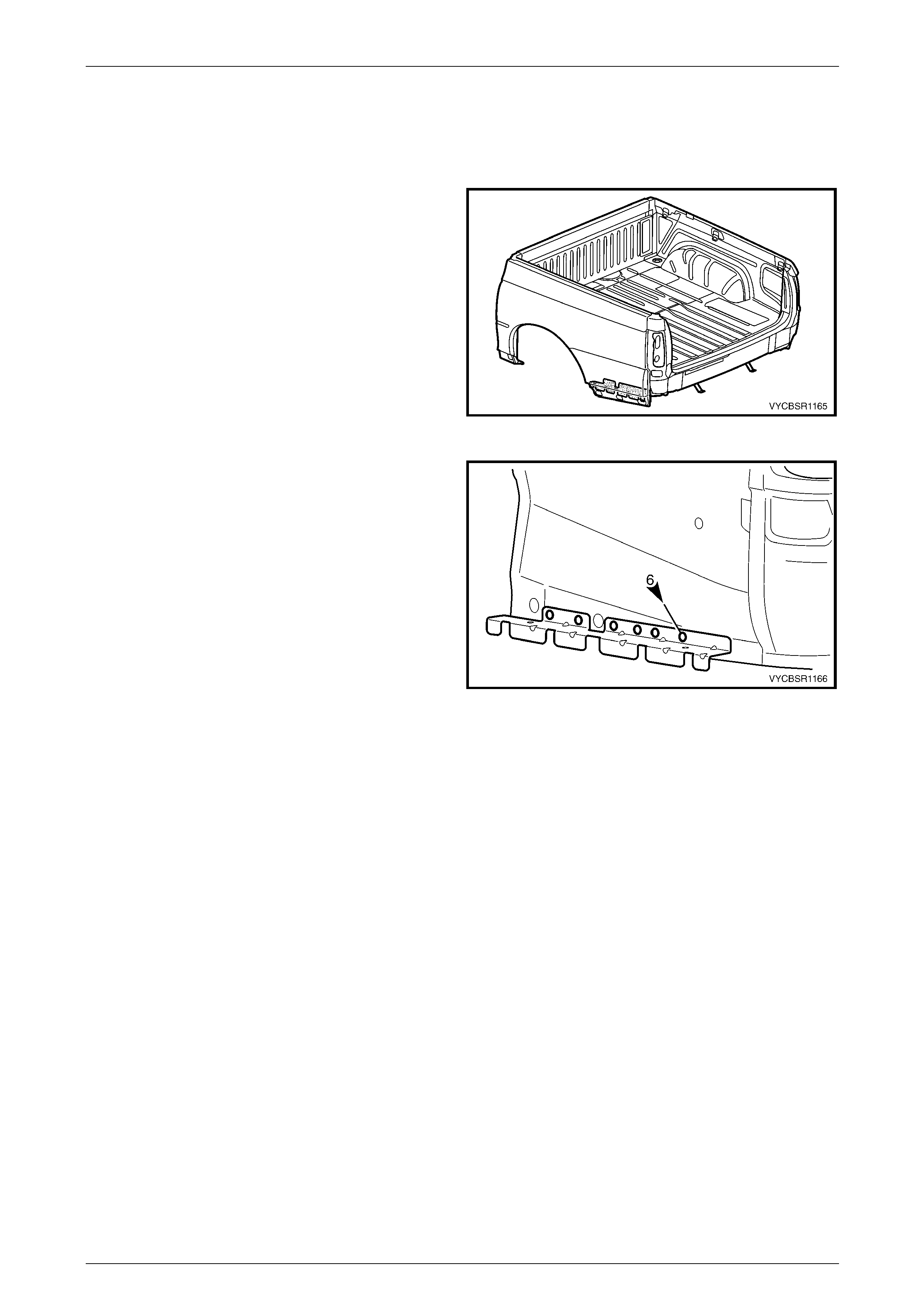
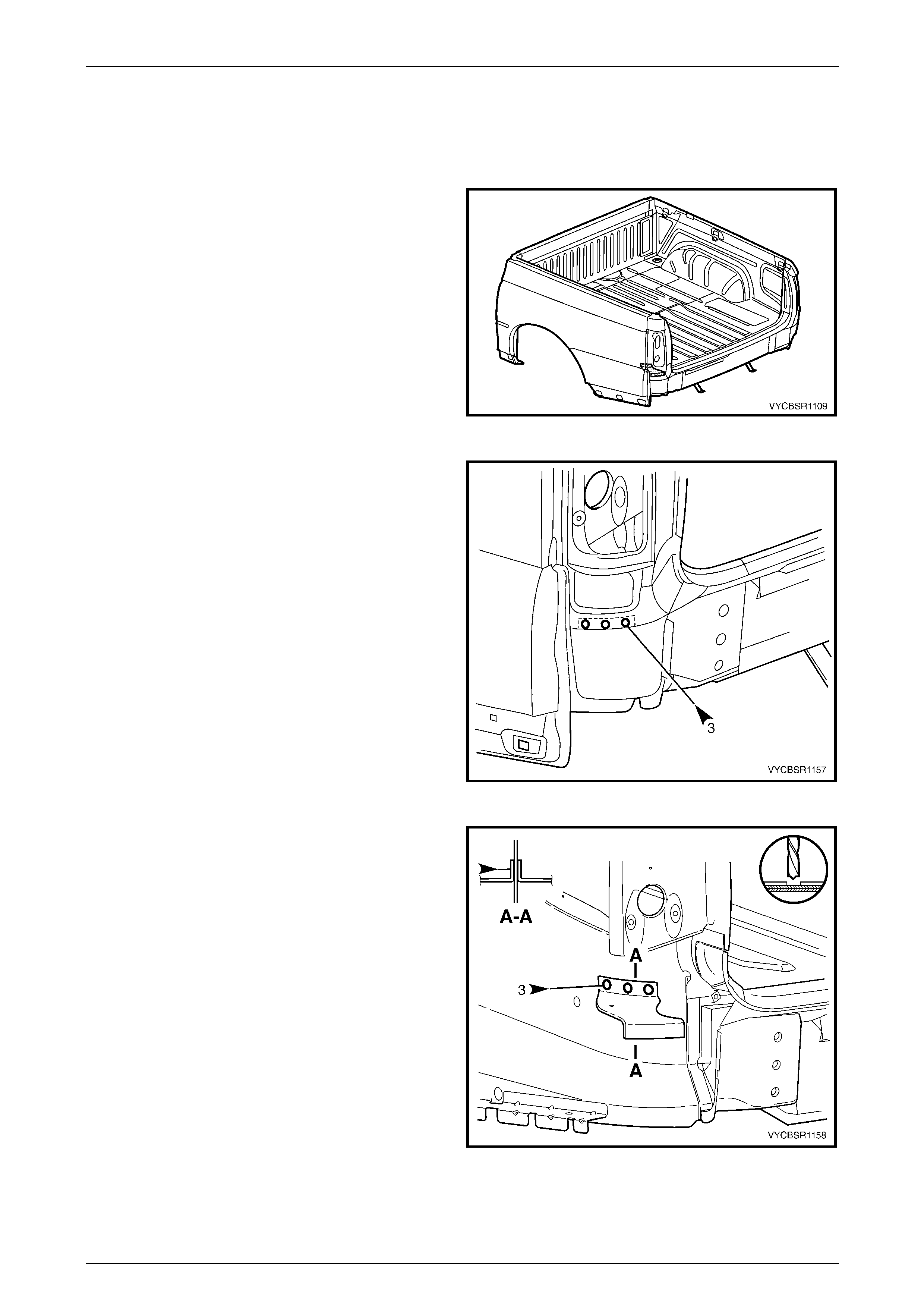
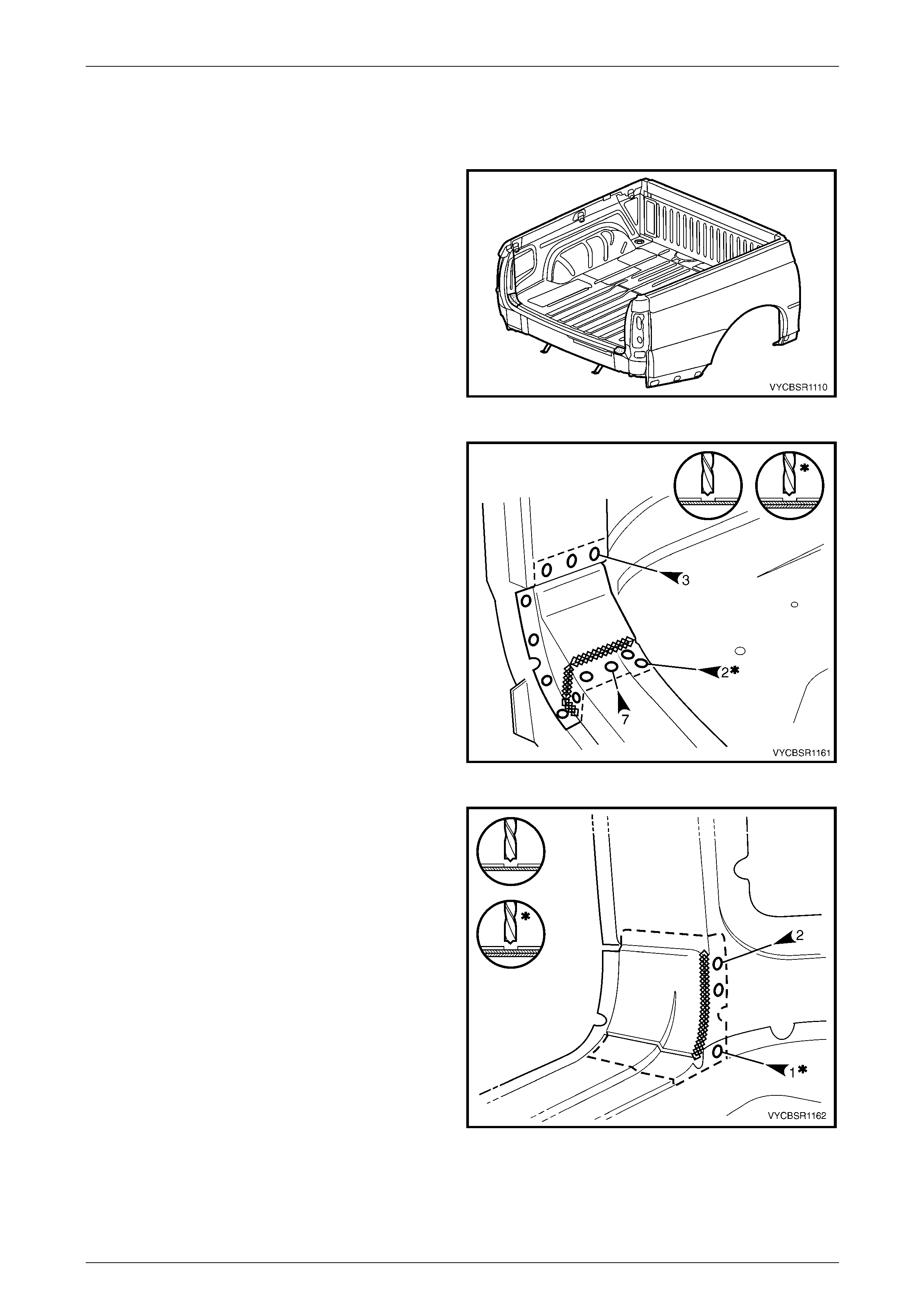
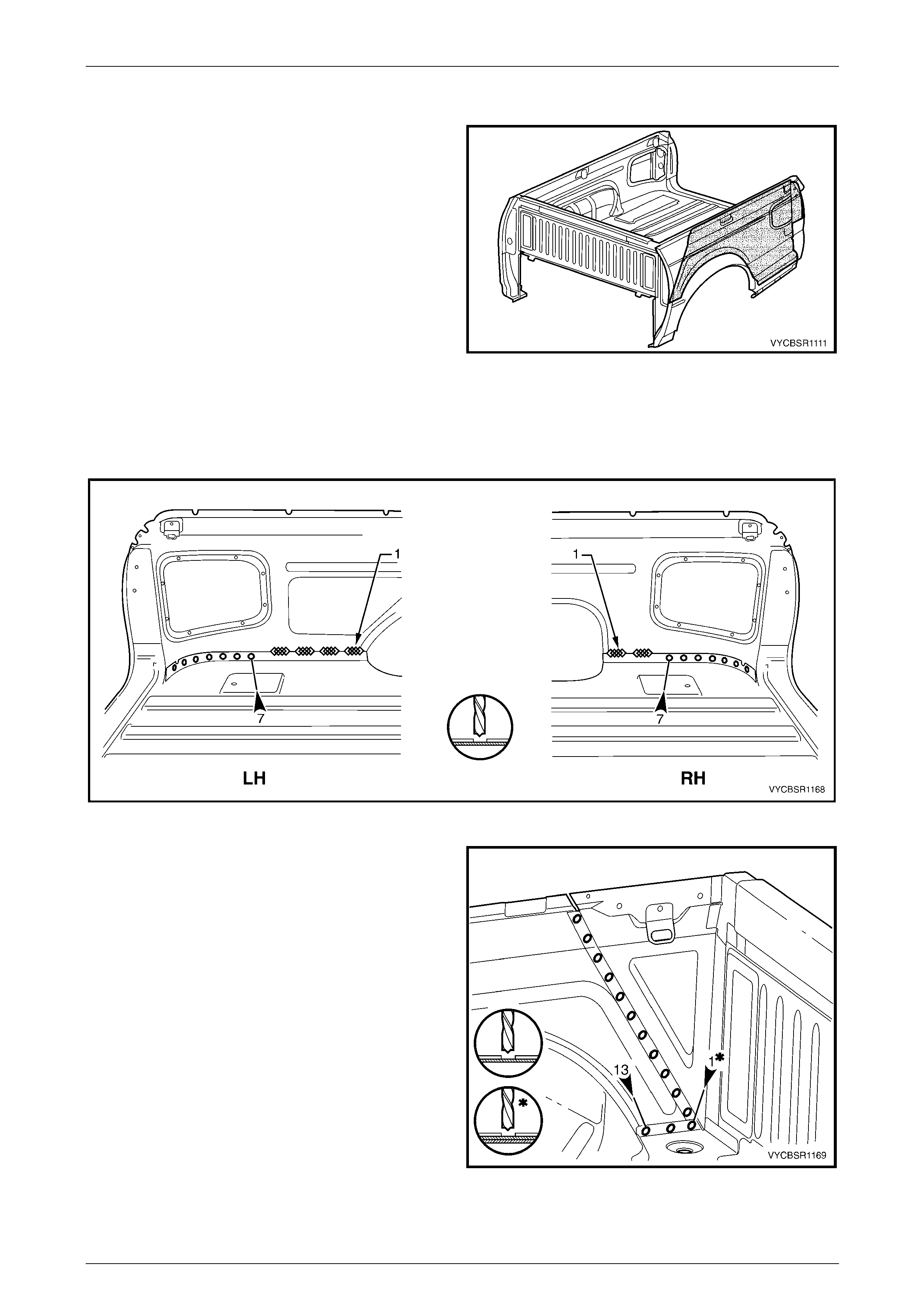
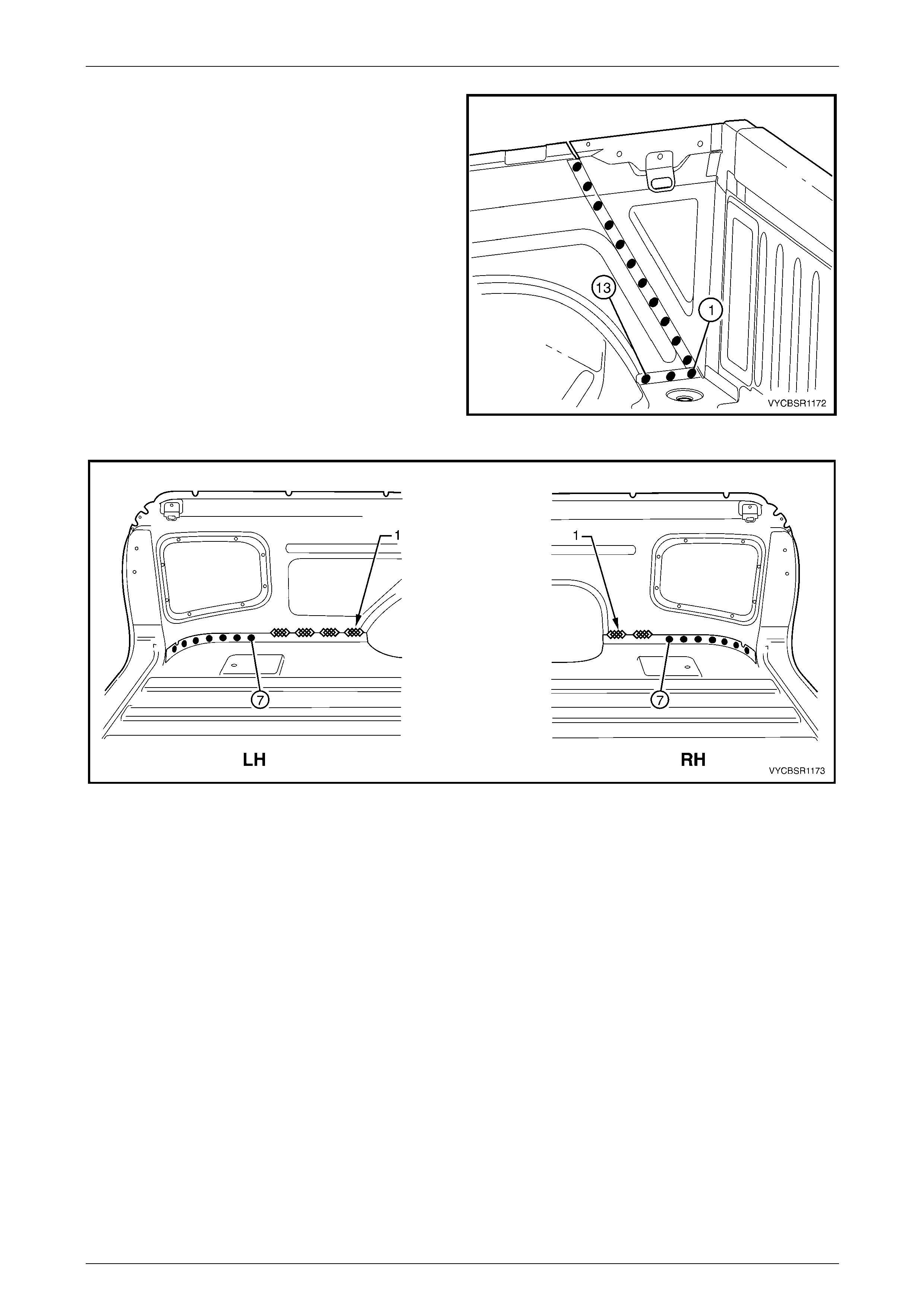
1.1 Body Rear Components
The shaded components in Figure 11–1 are those dealt with
in this Section.
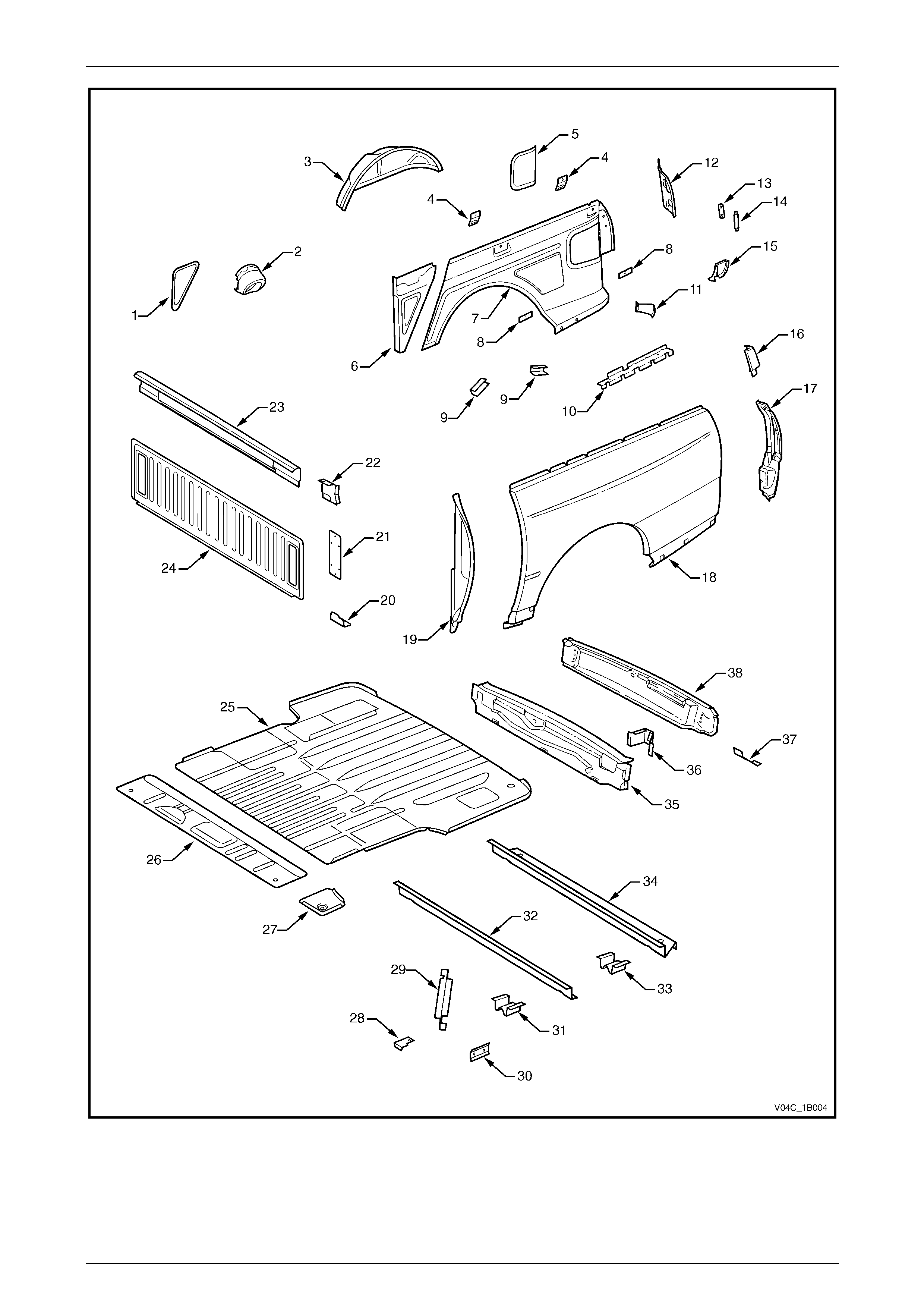
The components and assemblies shown in Figure 11–2 are
the parts serviced for MY 2003 VY Crew Cab vehicles which
form the basis of the repair procedures in this Section. F or a
detailed view of the body components, refer to
Section 3B Body Construction, Crew Cab.
NOTE
Always refer to an Authorised Dealer for spare
parts availability configurations.
Figure 11–1
Rear Tray Body Assembly, Crew Cab Page 11–4
Page 11–4
Figure 11–2

Rear Tray Body Assembly, Crew Cab Page 11–5
Page 11–5
Legend
1 Inner Side Panel Extension Cover, RH
2 Fuel Filler Pipe Housing, RH
3 Rear Wheelhouse Inner Panel
4 Cargo Tie Down Bracket
5 Rear Inner Side Panel Cover
6 Inner Side Panel Extension Assembly
7 Inner Side Panel
8 Cargo Tie Down Bracket Anchor Plate Assembly
9 Wheelhouse Filler Panel Bracket
10 Rear Quarter Closing Panel
11 Quarter Panel Rear Brace
12 Quarter Inner Lower Rear Extension
13 Endgate Striker Anchor Plate
14 Endgate Striker Anchor Plate Retainer
15 Quarter Lower Rear Panel
16 Quarter Panel Upper Extension
17 Quarter Panel Extension
18 Rear Quarter Panel*
19 Quarter Panel Front Gusset
20 Rear Body Front Bracket
21 Front End Panel Cover
22 Front Cover Attachment Beam
23 Front End Panel Sill Assembly
24 Front End Panel
25 Load Floor Panel
26 Load Floor Front Extension
27 Load Floor Panel Front Extension
28 Front End Panel Locator
29 Load Floor Panel Support
30 Load Floor Panel Side Support
31 Load Floor Panel Locator
32 Load Floor Panel Front Support
33 Load Floor Panel Locator Guide
34 Load Floor Panel Rear Support
35 Rear End Panel
36 Endgate Hinge Reinforcement
37 Rear Fascia Centre Bracket
38 Rear End Lower Panel
* 2WD shown, AWD is identical except for rear wheelhouse opening flare holes.
Rear Tray Body Assembly, Crew Cab Page 11–6
Page 11–6
2 Service Operations
2.1 Rear End Lower Panel – Replace
NOTE
• If the rear end panel (inner) is also to be
replaced, remove the rear end panels as an
assembly, refer to 2.3 Rear End Panel –
Replace.
• This procedure also includes the rear fascia
centre bracket.
Remove
1 Remove the adjacent bolt-on panels a nd components
as described in the appropriate Section of the
MY 2004 VY Regular Cab and Crew Cab Service
Information.
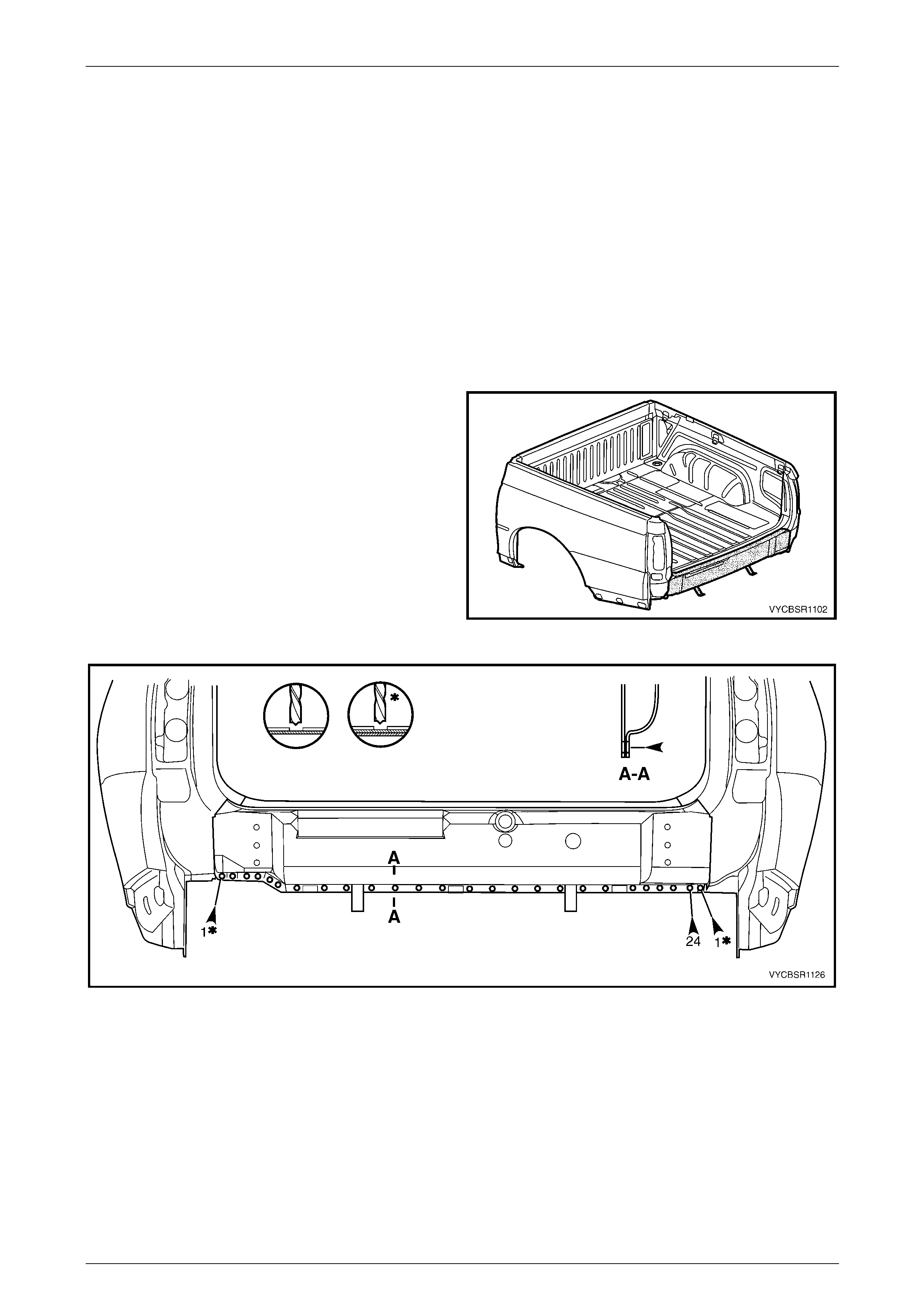
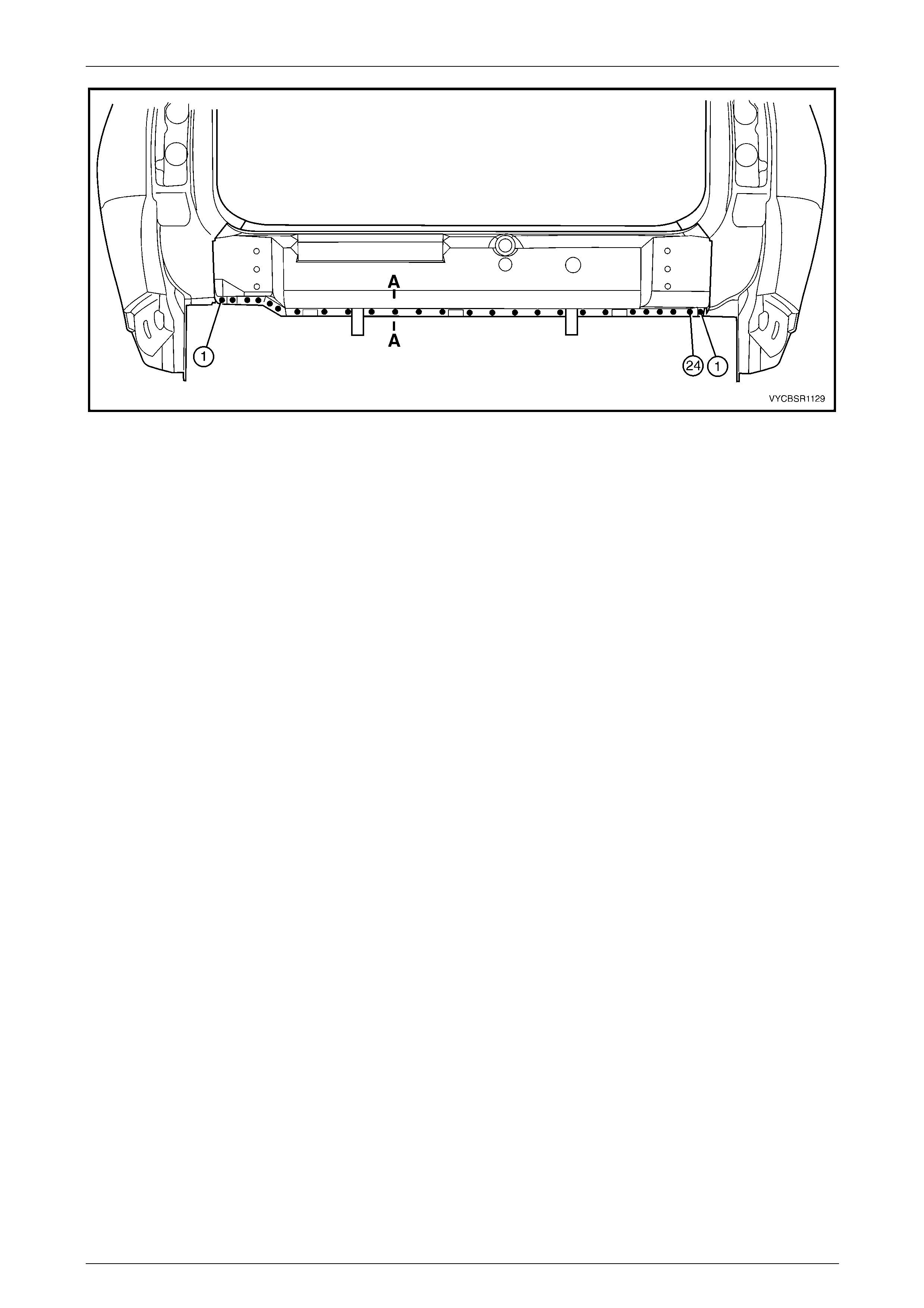
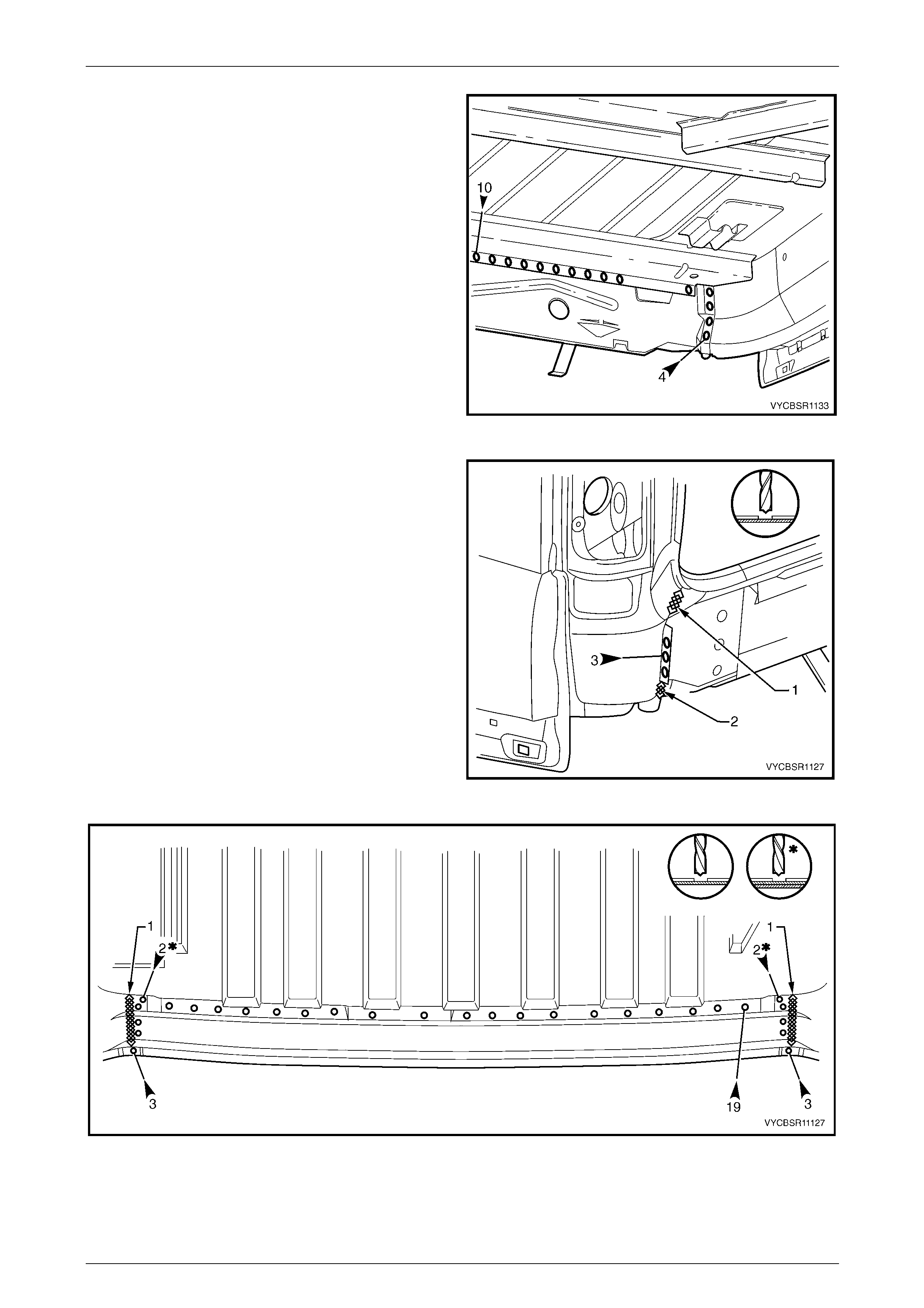
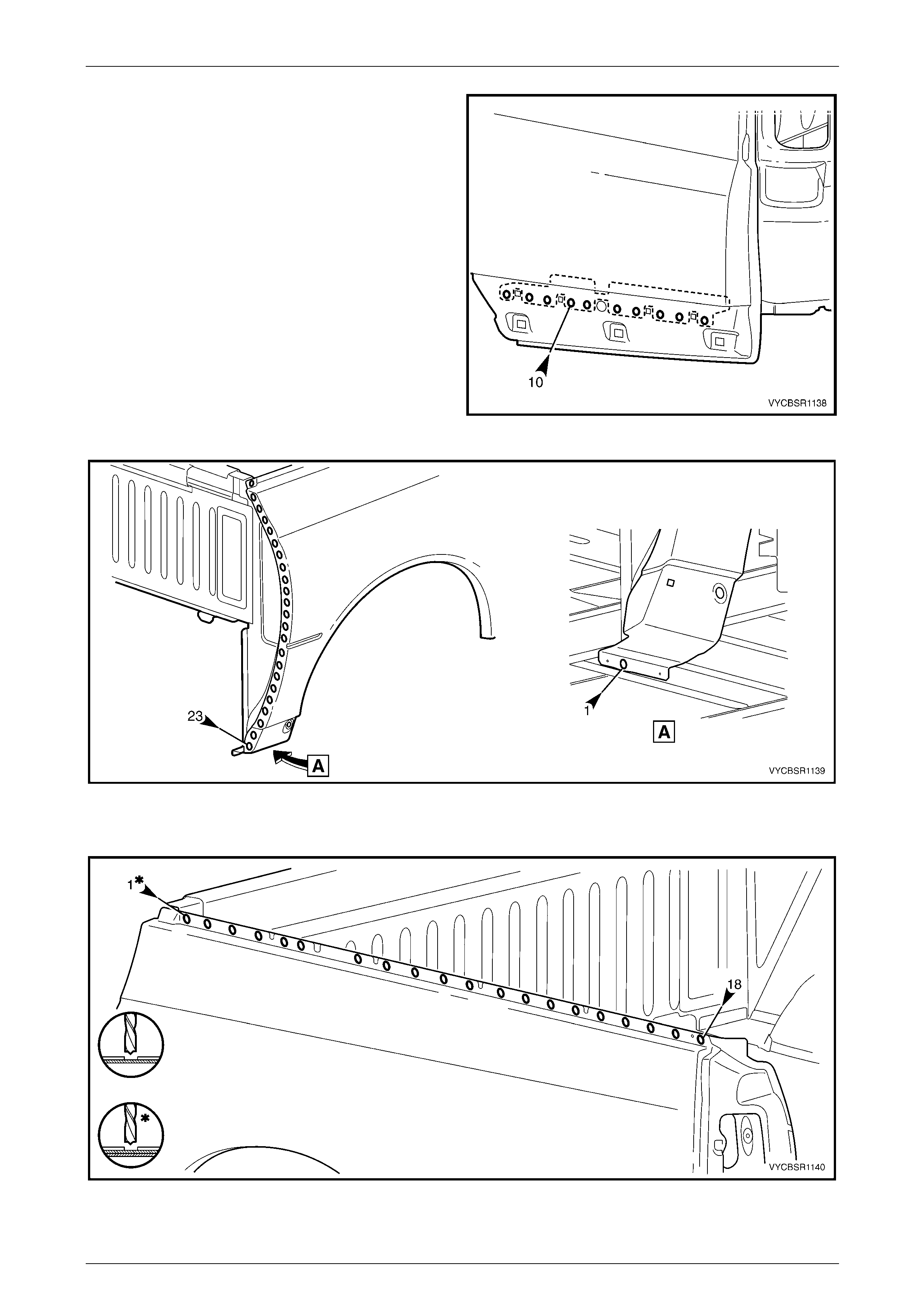
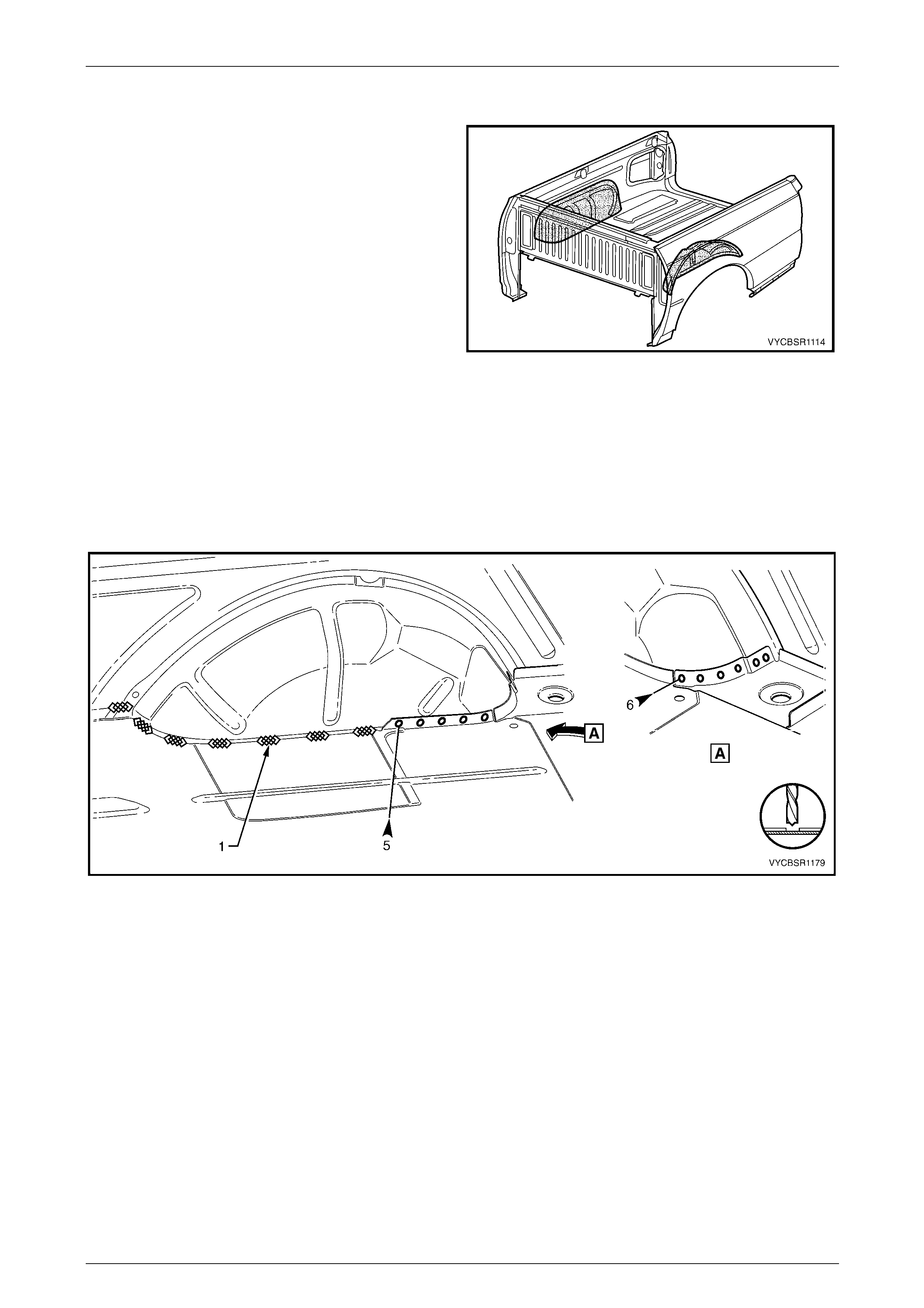
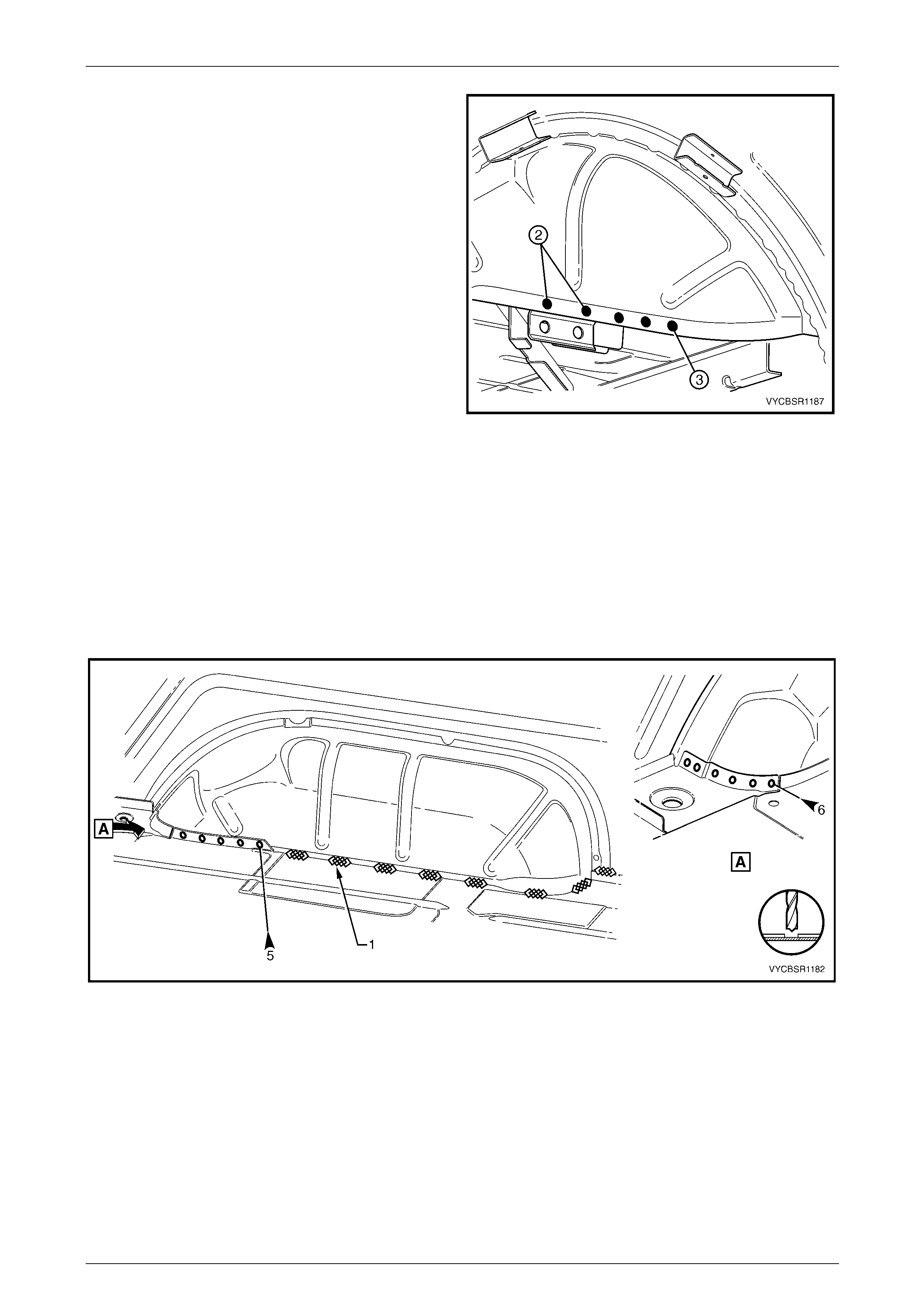
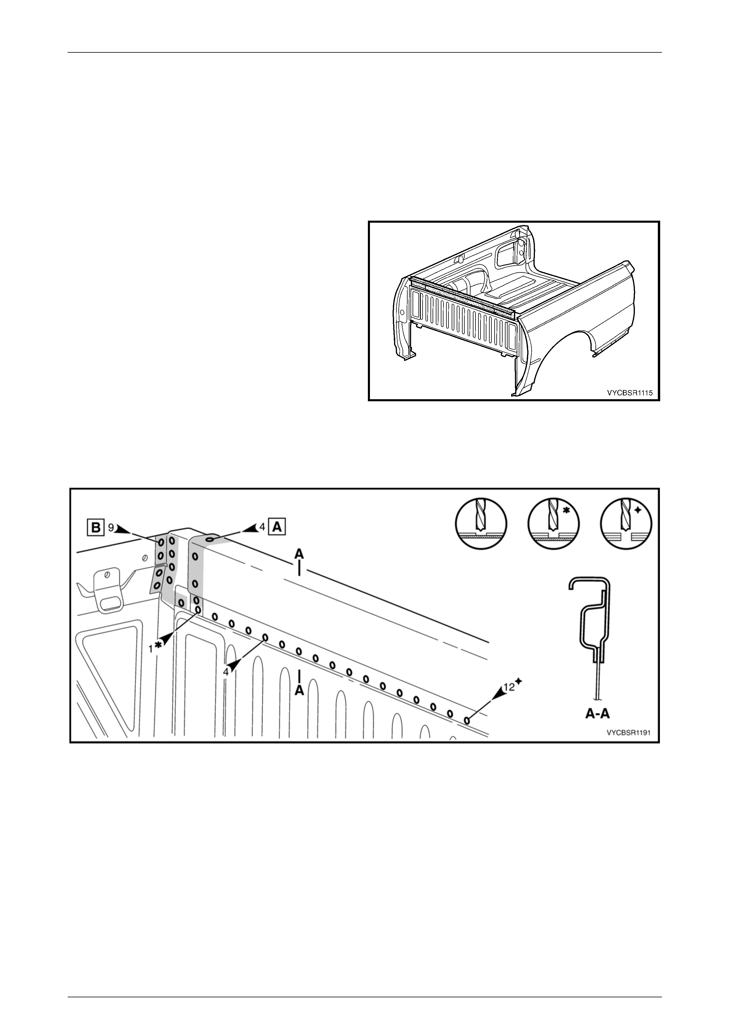
2 Spot cut the welds attaching the rear end lower panel
to the rear end panel and inner side pa nel, refer to
Figure 11–4.
Figure 11–3
Figure 11–4

Rear Tray Body Assembly, Crew Cab Page 11–7
Page 11–7
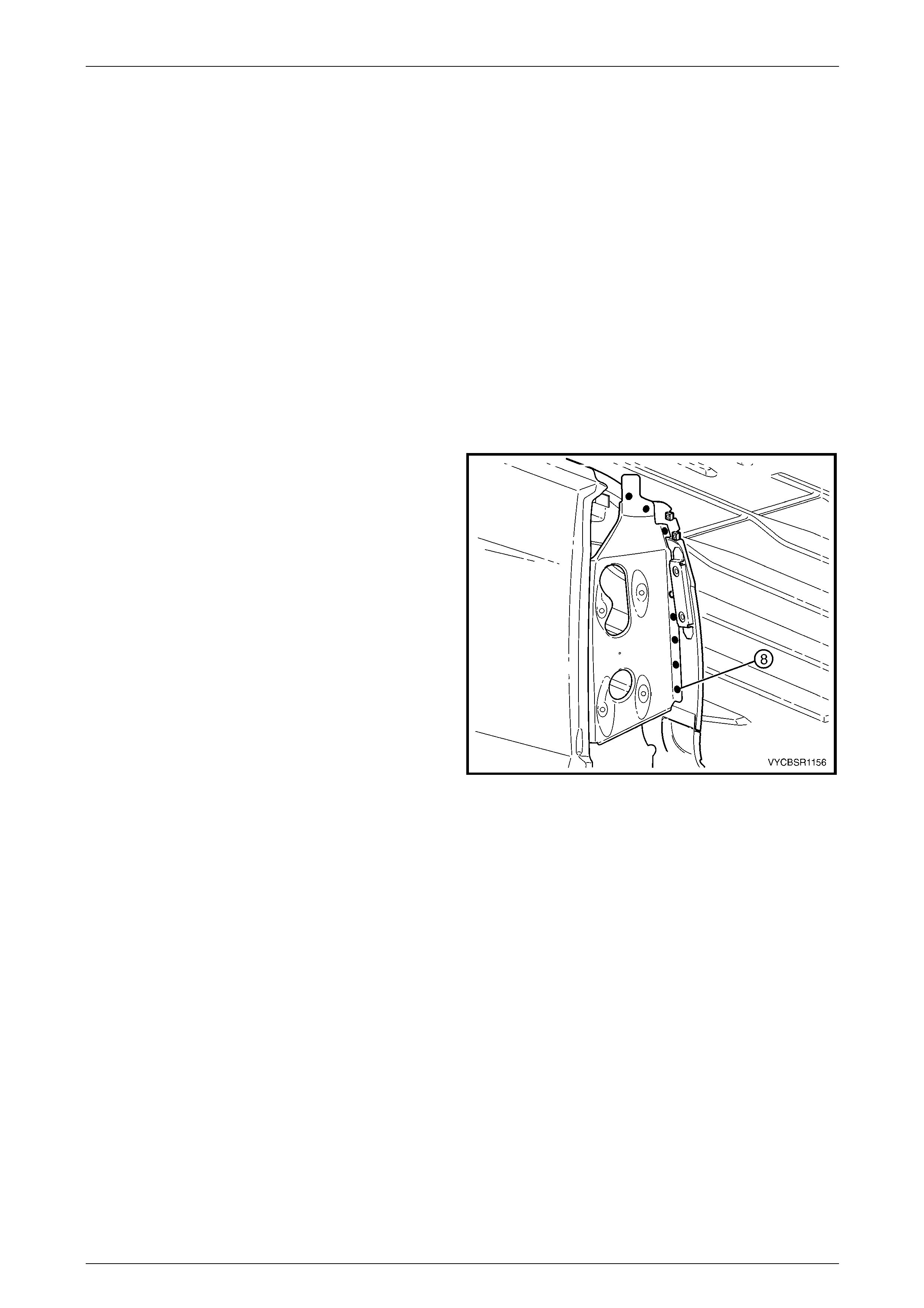
3 Grind off the MIG welds (1 & 2) attaching the rear end
lower panel to the quarter panel extens ion.
4 Spot cut the welds attaching the rear end lower panel
to the quarter panel extension.
5 Spot cut the welds attaching the rear end lower panel
to the rear end panel and quar ter lower rear panel,
refer to Figure 11–6.
6 Remove the rear end lower panel from the vehicle and
repair any damage to adjacent parts as required.
Figure 11–5
Figure 11–6
Replace
NOTE
• Spot welding is the preferred method for
attaching of panels and should be used
whenever possible. Where the spot welding
equipment available will not access the
required weld position, a plug weld should be
performed.
• The same number and position of spot welds
(or plug welds) should be used when
replacing the panel as was used during
manufacture, in order to maintain the original
structural strength of the vehicle.
1 As required, mark the new panel with drilling locations in preparation for plug welding. Drill holes as required.
2 Prepare all mating surfaces and treat with Weld Through Primer (Item 1) as required, refer to Section 3B,
5 Body Sealing, Adhesives & Dea deners.
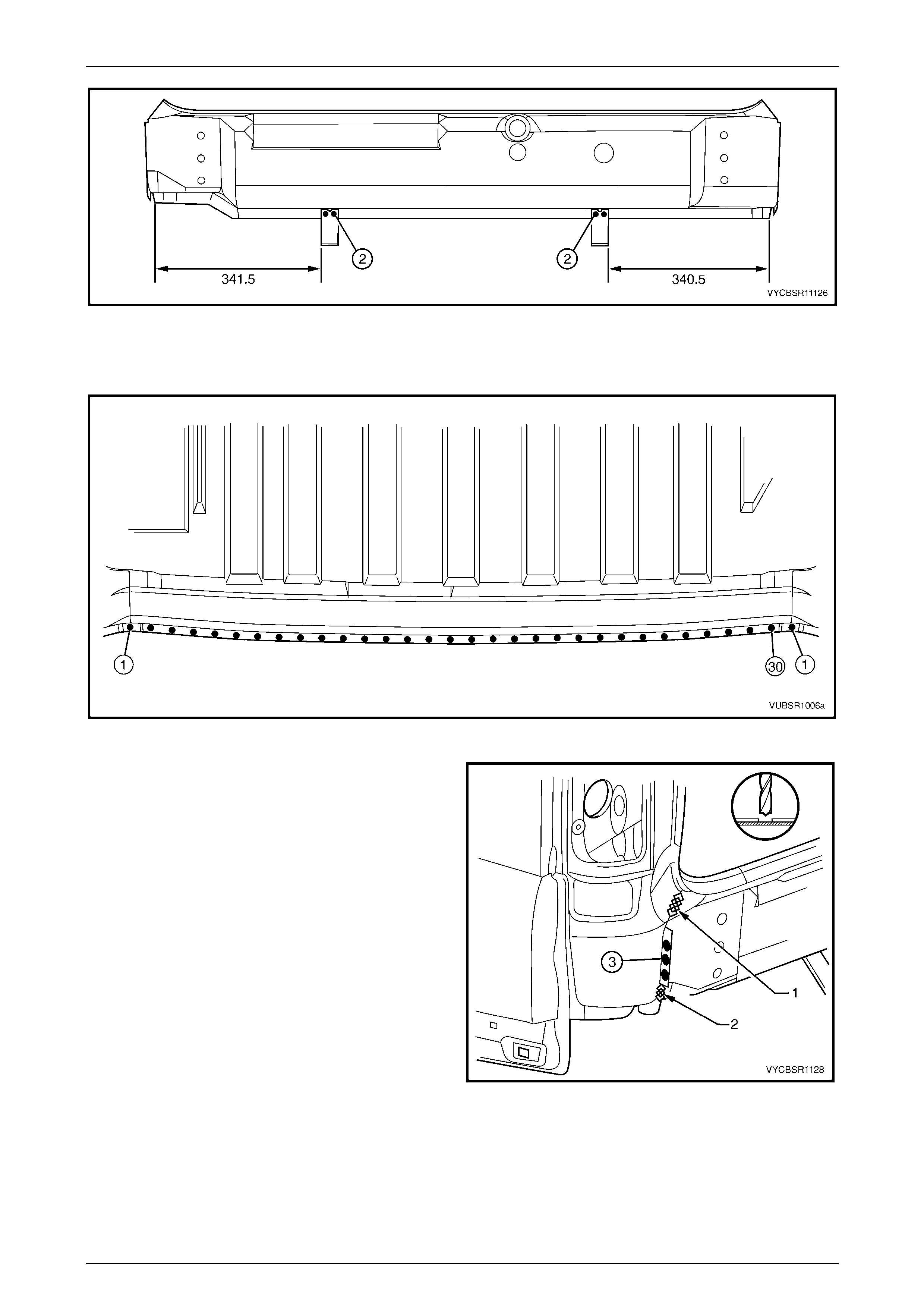
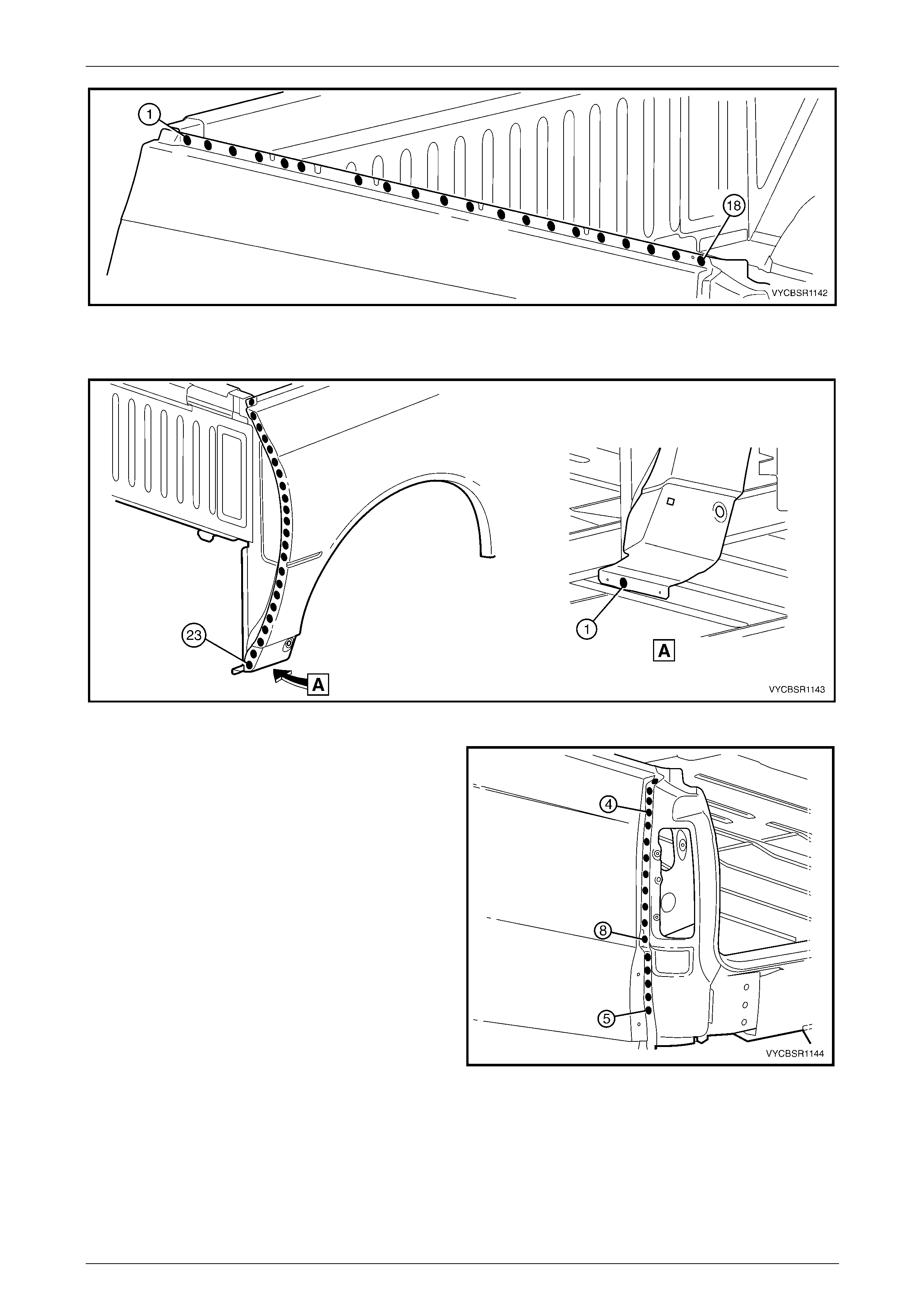
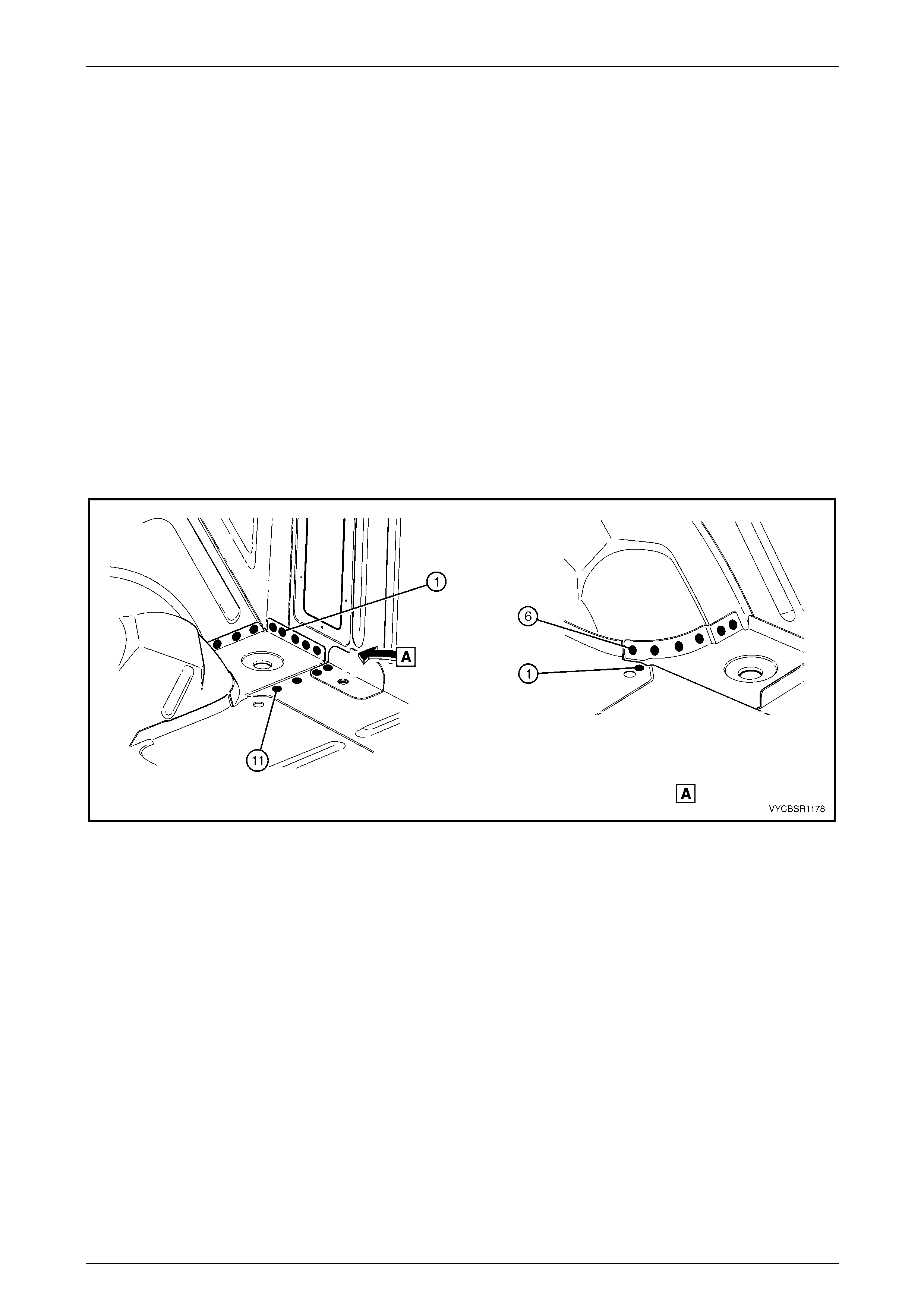
3 Position the rear fascia centre brackets in their correct positions and spot or plug weld each bracket to the rear end
lower panel, refer to Figure 11–7.
Rear Tray Body Assembly, Crew Cab Page 11–8
Page 11–8
Figure 11–7
4 Clamp the rear end lower panel in position on the vehicle and spot or plug weld to the rear end pan el and quarter
lower rear panel, refer to Figure 11–8.
Figure 11–8
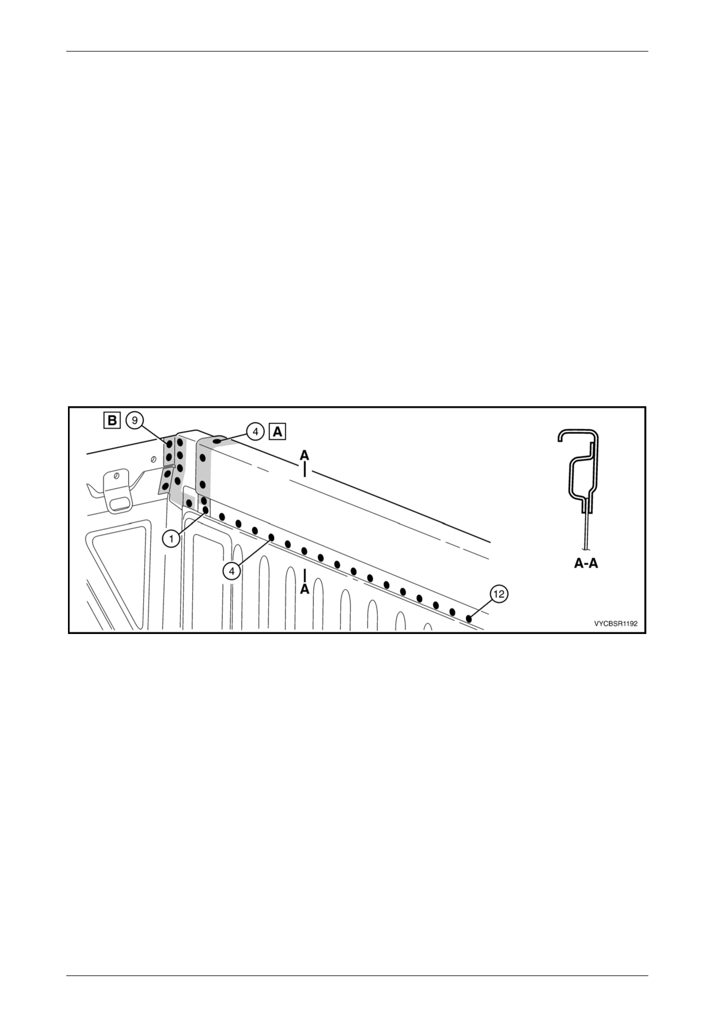
5 Spot or plug weld the rear end lo wer panel to the
quarter panel extension.
6 MIG weld two places (1 & 2), the rear end lower panel
to the quarter panel extension.
7 Spot or plug weld the rear end lo wer panel to the rear
end panel and the inner side pan el, refer to
Figure 11–10.
Figure 11–9
Rear Tray Body Assembly, Crew Cab Page 11–9
Page 11–9
Figure 11–10
8 Refinish and paint panels and other components as required, refer to Section 3, 1.3 Paint Refinishing in the MY
2003 VY and V2 Series Service Manual Supplement, Body Structure Repair.
9 Apply Joint Sealer (Item 3) as required, refer to Section 3B, 5 Body Sealing, Adhesives & Deadeners.
10 Apply Cavity Wax (Item 8) as required to the inside of any box sections or areas inaccessible to paint, refer to
Section 3B, 6 Cavity Wax.
11 Install the remaining compon ents as described in the appropriate Secti on of the MY 2004 VY Regular Cab and
Crew Cab Service Information.
Rear Tray Body Assembly, Crew Cab Page 11–10
Page 11–10
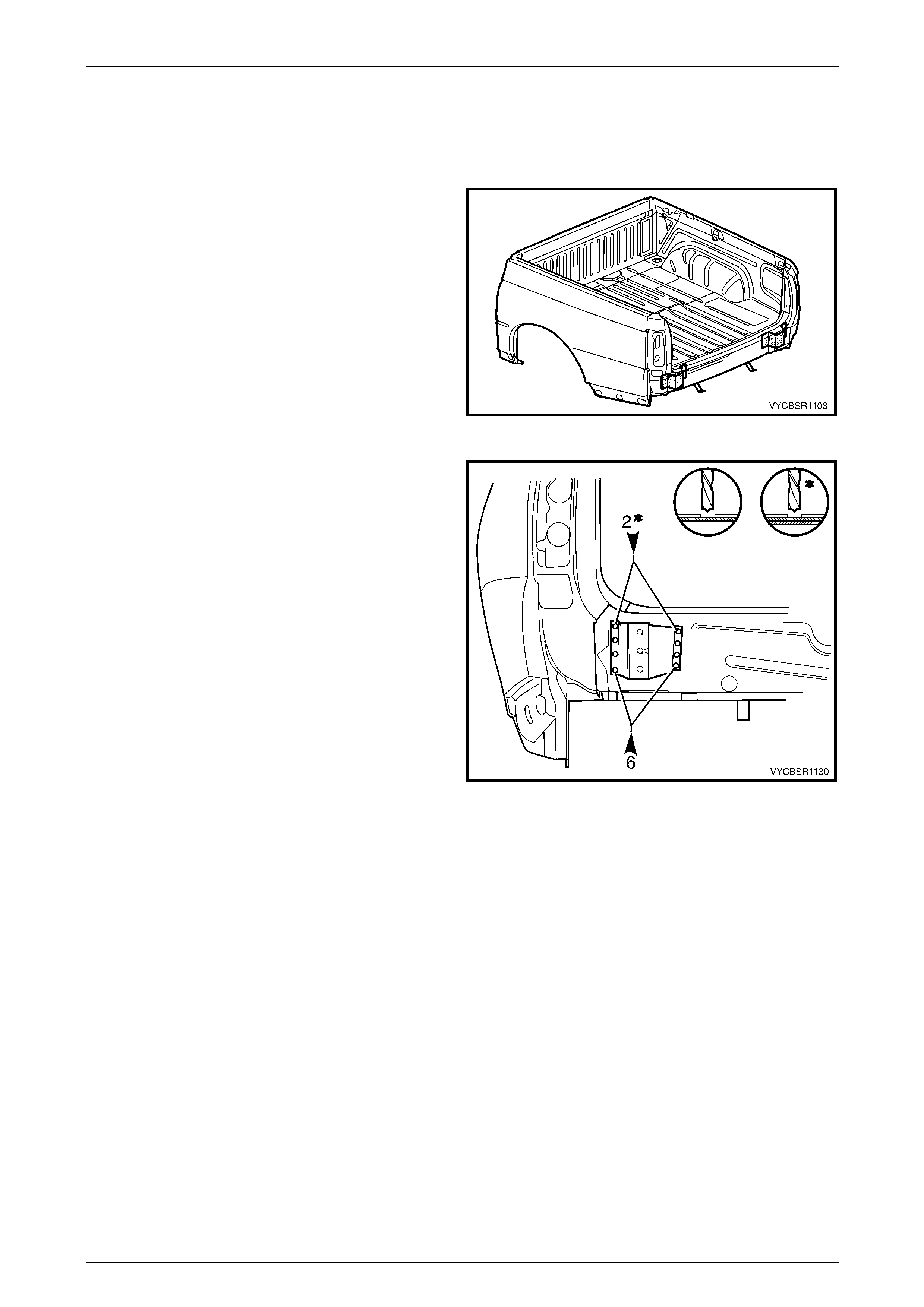
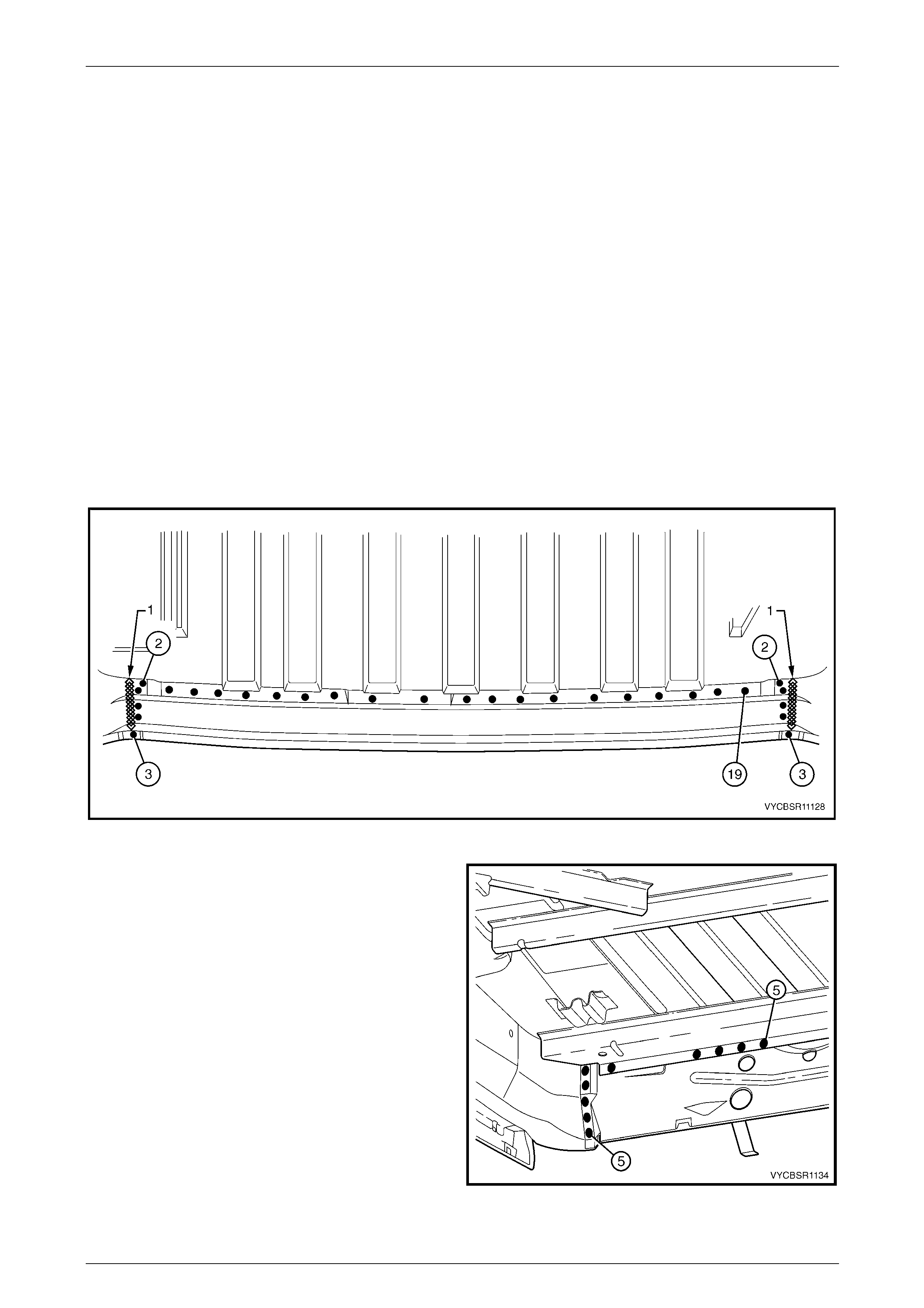
2.2 Endgate Hinge Reinforcement – Replace
Remove
1 Remove the adjacent bolt-on panels a nd components
as described in the appropriate Section of the
MY 2004 VY Regular Cab and Crew Cab Service
Information.
2 Remove the rear end lower panel, refer to
2.1 Rear End Lower Panel – Replace.
Figure 11–11
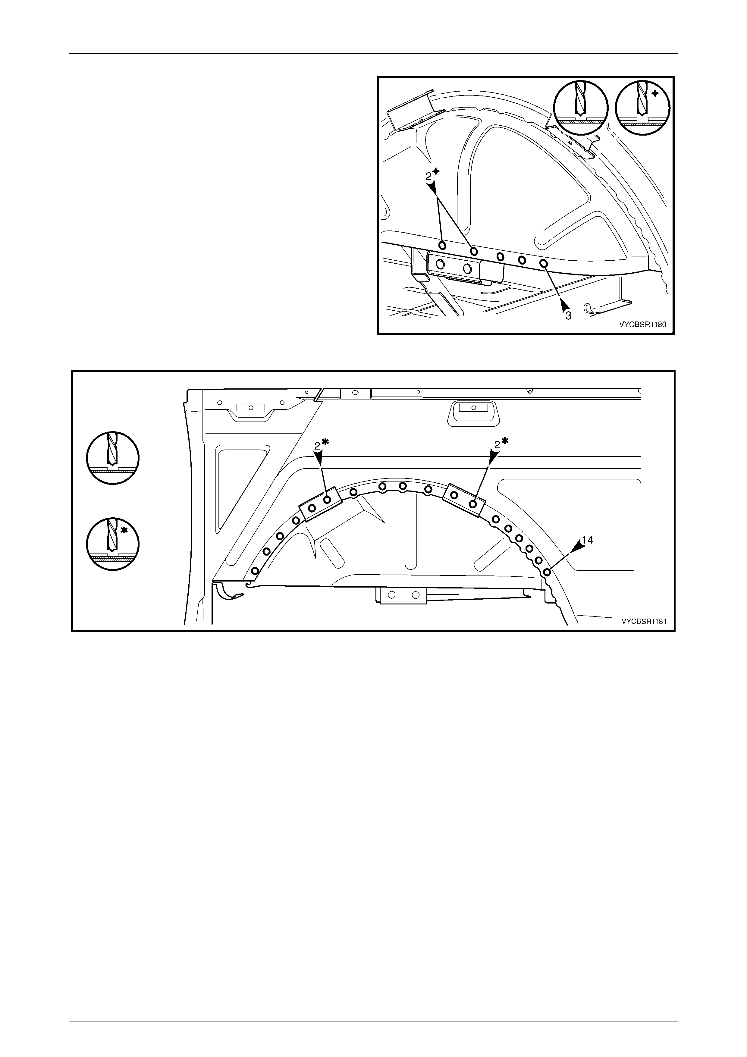
3 Spot cut the six lower welds attaching the endg ate
hinge reinforcement to the rear end pa nel.
4 Spot cut the two upper welds attaching the e ndgate
hinge reinforcement to the rear end pa nel and load
floor panel rear support.
NOTE
Cut through the rear end panel as well if it is to
be removed.
5 Remove the endgate hinge reinforceme nt the n repair
any damage to adjacent parts as required
Figure 11–12
Replace
NOTE
• Spot welding is the preferred method for
attaching of panels and should be used
whenever possible. Where the spot welding
equipment available will not access the
required weld position, a plug weld should be
performed.
• The same number and position of spot welds
(or plug welds) should be used when
replacing the panel as was used during
manufacture, in order to maintain the original
structural strength of the vehicle.
1 As required, mark the new panel with drilling locations in preparation for plug welding. Drill holes as required.
2 Prepare all mating surfaces and treat with Weld Through Primer (Item 1) as required, refer to Section 3B,
5 Body Sealing, Adhesives & Dea deners.
Rear Tray Body Assembly, Crew Cab Page 11–11
Page 11–11
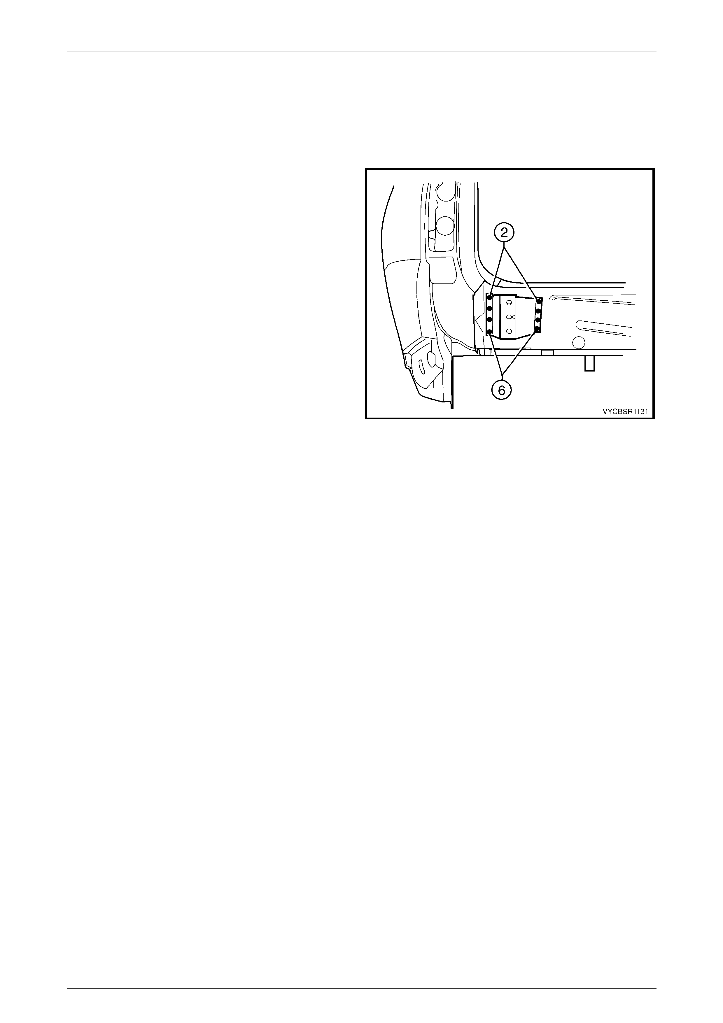
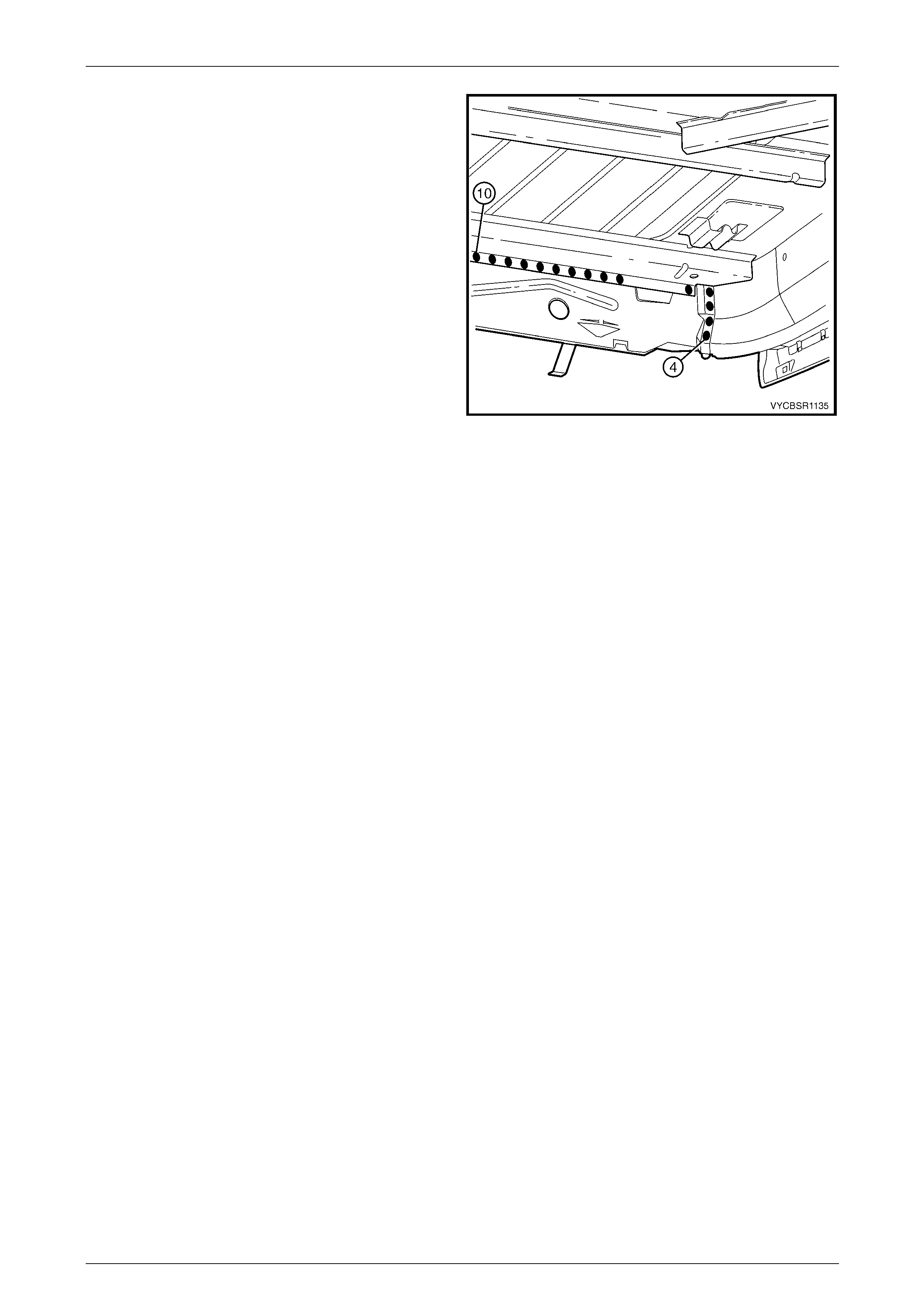
3 Install the endgate hinge reinforcement in position on the rear end panel.
NOTE
Test fit the rear end lower panel to ensure the
endgate hinge mounting holes align.
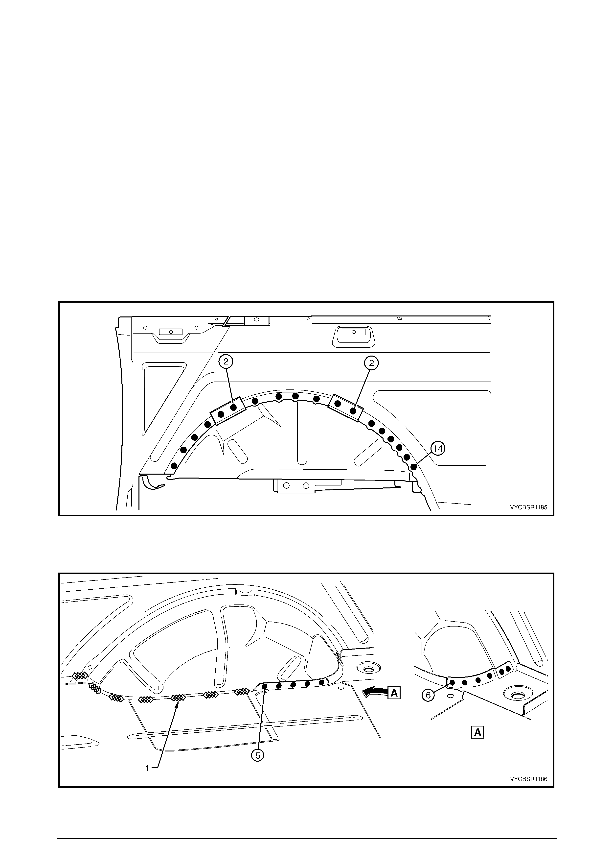
4 Spot or plug weld the two upper welds attaching the
endgate hinge reinforc ement to the rear end panel and
load floor panel rear support.
5 Spot or plug weld the six lower welds attaching
endgate hinge reinforc ement to the rear end panel.
6 Install the rear end lower panel, refer to
2.1 Rear End Lower Panel – Replace.
7 Refinish and paint panels and other components as
required, refer to Section 3, 1.3 Paint Refinishing in
the MY 2003 VY and V2 Series Service Manual
Supplement, Body Structure Repair.
8 Apply Joint Sealer (Item 3) as required, refer to
Section 3B, 5 Body Sealing, Adhesives & Deadeners.
9 Apply Cavity Wax (Item 8) as required to the inside of
any box sections or areas inaccessible to paint, refer
to Section 3B, 6 Cavity Wax.
10 Install the remaining components as described in the
appropriate Section of the MY 2004 VY Regu lar Cab
and Crew Cab Service Information.
Figure 11–13
Rear Tray Body Assembly, Crew Cab Page 11–12
Page 11–12
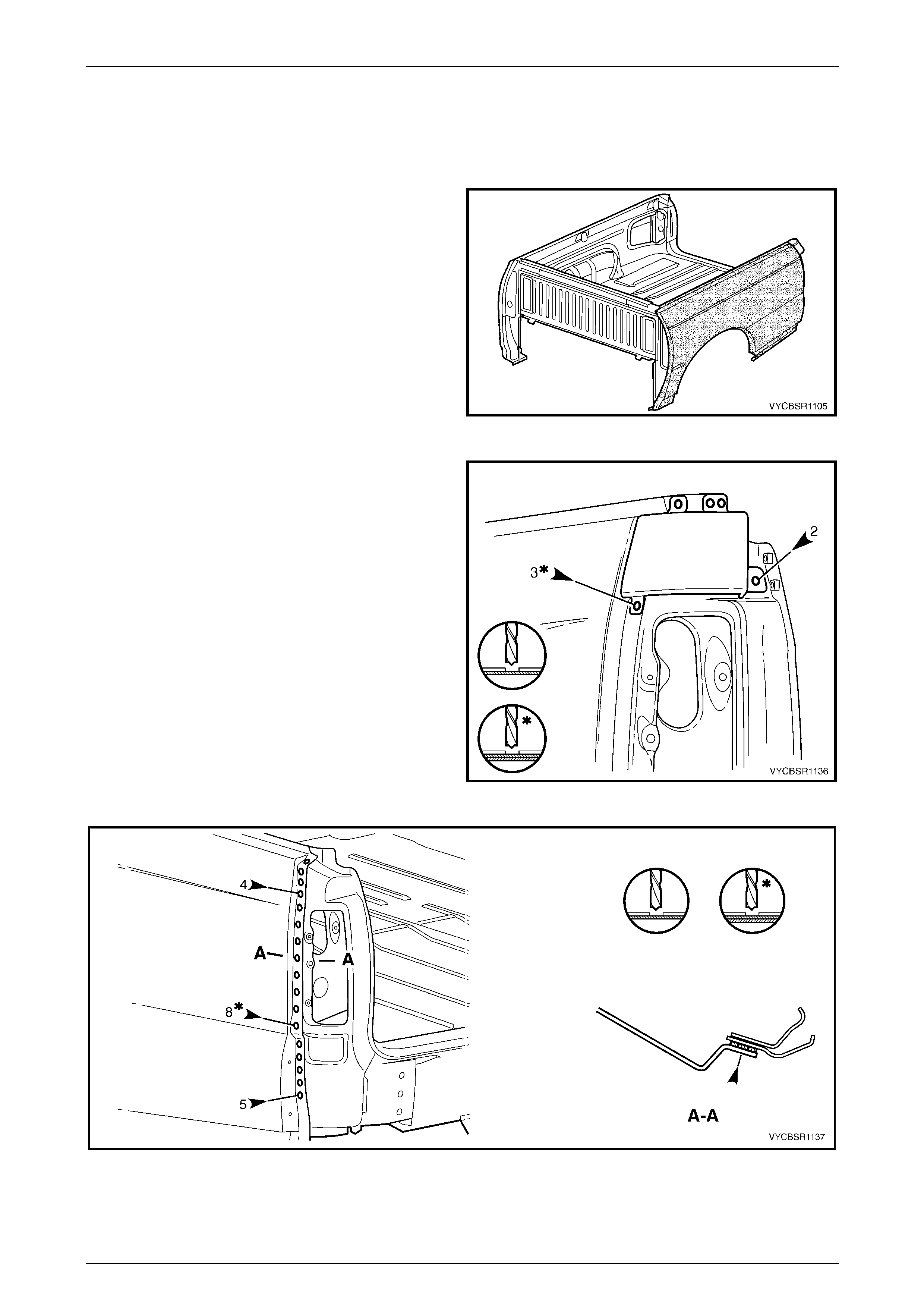
2.3 Rear End Panel – Replace
NOTE
This procedure describes the removal of the rear
end lower panel, endgate hinge reinforcement
and rear end panel as an assembly. As the
panels are supplied individually, this procedure
contains the replacement of the rear end panel
only. Reference should be then made to
2.2 Endgate Hinge Reinforcement – Replace
and 2.1 Rear End Lower Panel – Replace for
the relevant replacement procedures of the
remaining panels.
Remove
1 Remove the adjacent bolt-on panels a nd components
as described in the appropriate Section of the
MY 2004 VY Regular Cab and Crew Cab Service
Information.
Figure 11–14
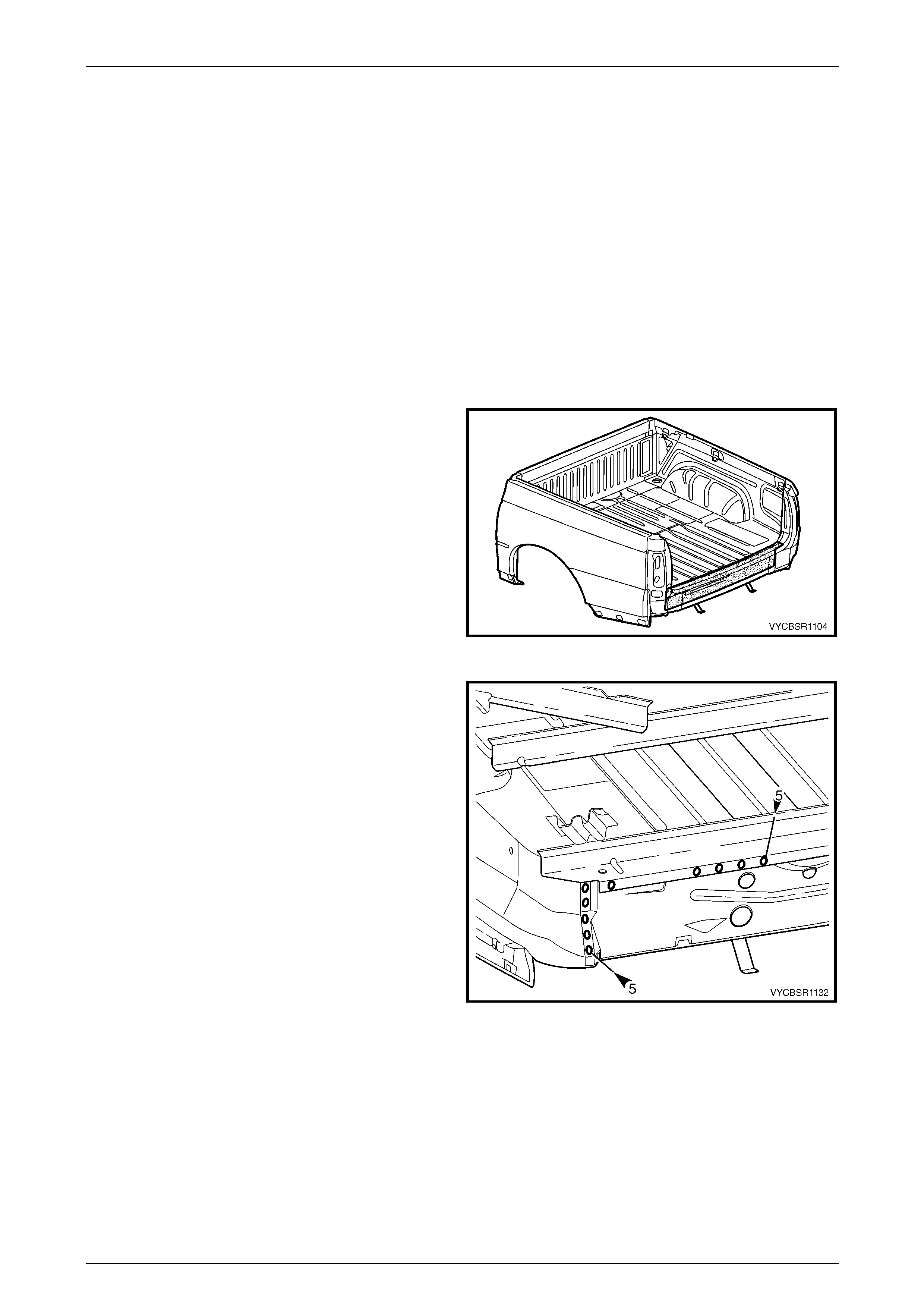
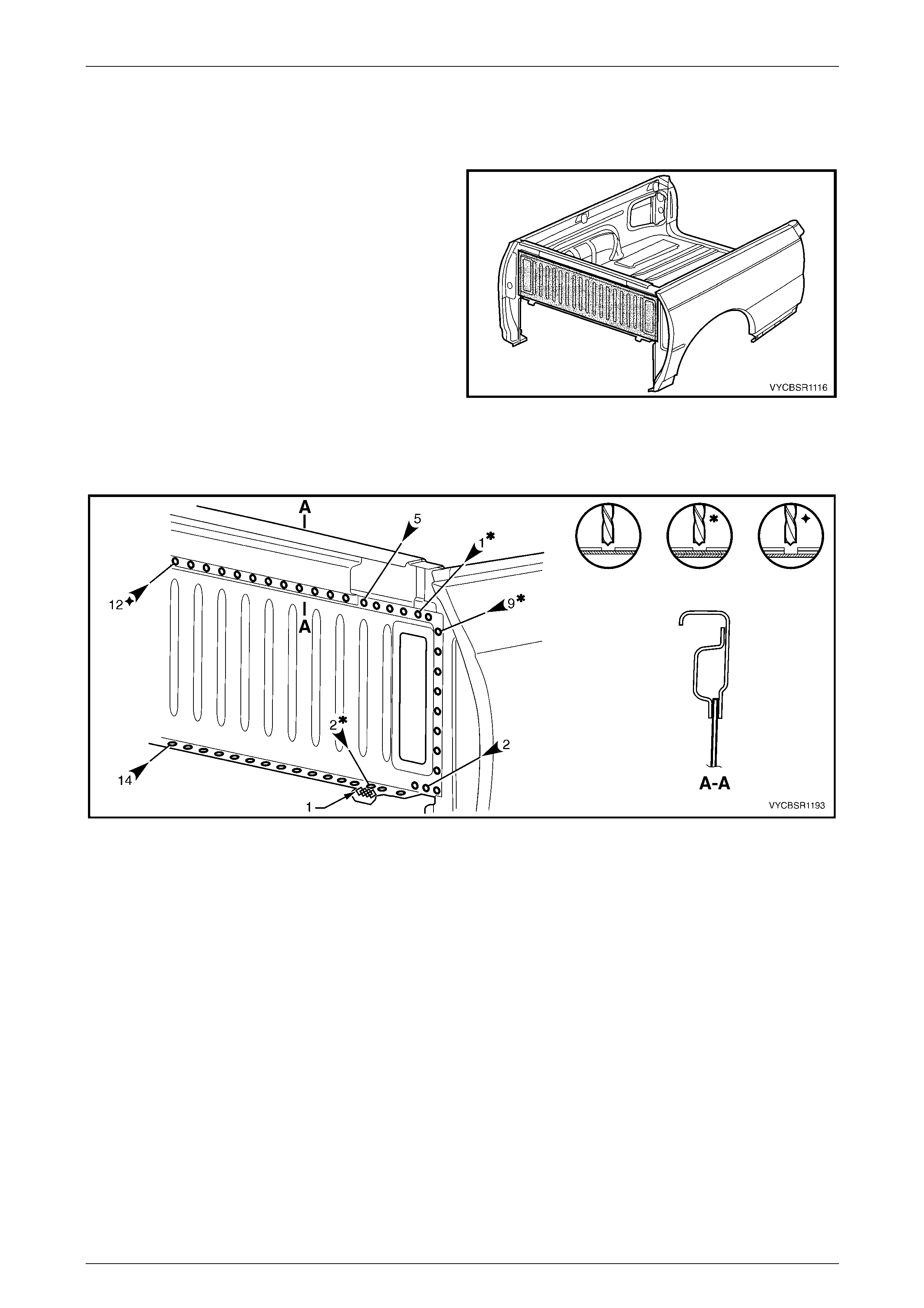
2 From underneath the vehicle, spot cut the welds
attaching the right-hand side of the rear end panel
assembly to the load floor panel rear support and inner
side panel.
Figure 11–15
Rear Tray Body Assembly, Crew Cab Page 11–13
Page 11–13
3 From underneath the vehicle, spot cut the welds
attaching the left-hand side of the rear end panel
assembly to the load floor panel rear support and inner
side panel.
Figure 11–16
4 Grind off the MIG welds (1 & 2) attaching the rear end
lower panel to the quarter panel extens ion.
5 Spot cut the welds attaching the rear end lower panel
to the quarter panel extension.
6 Grind off the MIG weld each side (1), attaching the
rear end panel to the quarter lower rear panel, refer to
Figure 11–18.
7 Spot cut welds attaching the rear end pa nel to the
quarter lower rear panel and l oad floor panel.
8 Remove the rear end panel assembl y from the vehicle
and repair any dama ge to adjacent parts as required.
Figure 11–17
Figure 11–18
Rear Tray Body Assembly, Crew Cab Page 11–14
Page 11–14
Replace
NOTE
• Spot welding is the preferred method for
attaching of panels and should be used
whenever possible. Where the spot welding
equipment available will not access the
required weld position, a plug weld should be
performed.
• The same number and position of spot welds
(or plug welds) should be used when
replacing the panel, as was used during
manufacture, in order to maintain the original
structural strength of the vehicle.
1 As required, mark the new panel with drilling locations in preparation for plug welding. Drill holes as required.
2 Prepare all mating surfaces and treat with Weld Through Primer (Item 1) as required, refer to Section 3B,
5 Body Sealing, Adhesives & Dea deners.
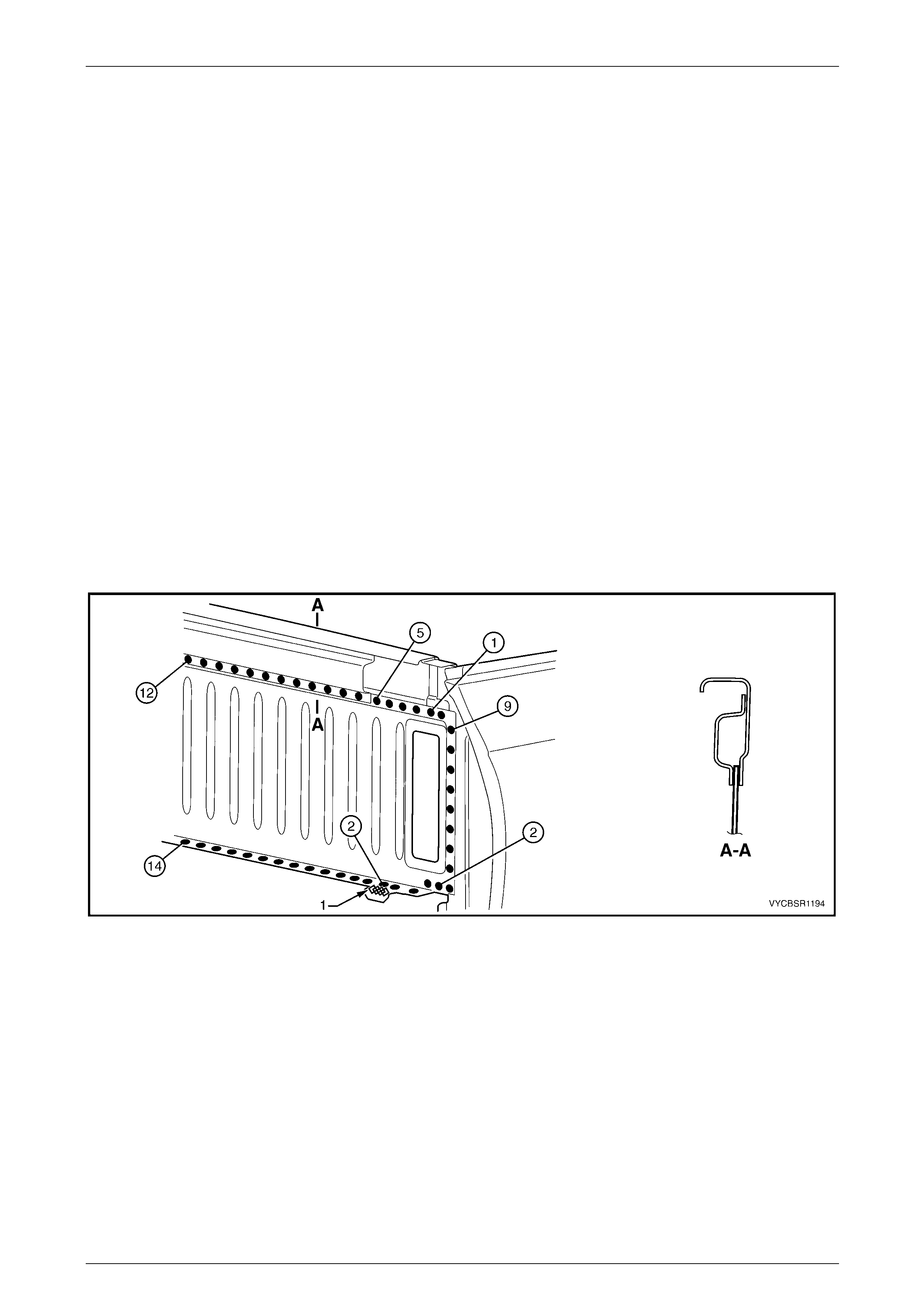
3 Clamp the rear end panel in p ositio n on the vehicle and spot or plug weld to the load floor panel and quar ter lower
rear panel, refer to Figure 11–19.
4 MIG weld each side (1), attaching the rear end panel to the quarter lower rear panel.
Figure 11–19
5 From underneath the vehicle, spot or plug weld the
right-hand side of the rear end panel assembly to the
load floor panel rear support and in ner side panel.
Figure 11–20
Rear Tray Body Assembly, Crew Cab Page 11–15
Page 11–15
6 From underneath the vehicle, spot or plug weld the
left-hand side of the rear end panel assembly to the
load floor panel rear support and in ner side panel.
7 Install the endgate hinge reinforcements, refer to
2.2 Endgate Hinge Reinforcement – Replace.
8 Clean up the welds and a pply primer to any bare
metal.
9 Install the rear end lower panel, refer to
2.1 Rear End Lower Panel – Replace.
10 Refinish and paint panels and other components as
required, refer to Section 3, 1.3 Paint Refinishing in
the MY 2003 VY and V2 Series Service Manual
Supplement, Body Structure Repair.
11 Apply Joint Sealer (Item 3) as required, refer to
Section 3B, 5 Body Sealing, Adhesives & Deadeners.
12 Apply Cavity Wax (Item 8) as required to the inside of
any box sections or areas inaccessible to paint, refer
to Section 3B, 6 Cavity Wax. Figure 11–21
13 Install the remaining compon ents as described in the appropriate Secti on of the MY 2004 VY Regular Cab and
Crew Cab Service Information.
Rear Tray Body Assembly, Crew Cab Page 11–16
Page 11–16
2.4 Rear Quarter Panel – Replace
Remove
1 Remove the rear tray body assembly from the vehicle.
This is required to provide access to the welds along
the front edge of the rear quarter panel. Refer to
Section 1B Sheetmetal in the MY 2004 VY Regular
Cab and Crew Cab Service Information.
2 Remove the adjacent bolt-on panels a nd components
as described in the appropriate Section of the
MY 2004 VY Regular Cab and Crew Cab Service
Information.
Figure 11–22
3 To access the spot welds underneath, spot cut the
welds attaching the quarter panel upper extension and
remove the extension.
4 Spot cut the welds attaching the rear quarter panel to
the quarter panel extension, refer to F igure 11 –24.
Figure 11–23
Figure 11–24
Rear Tray Body Assembly, Crew Cab Page 11–17
Page 11–17
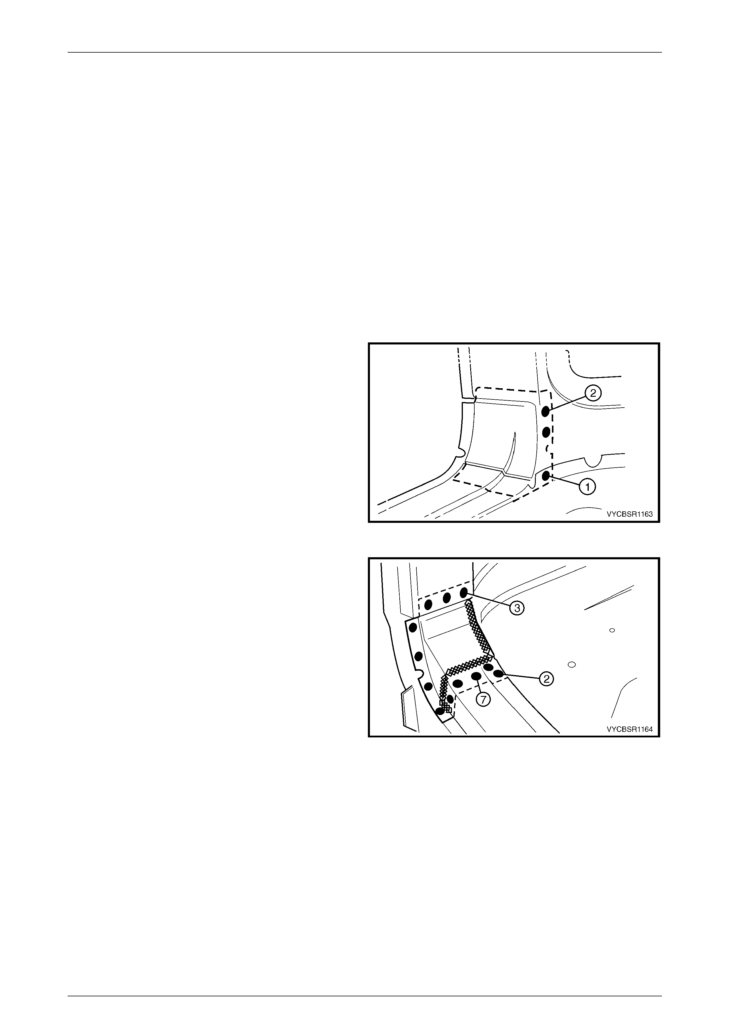
5 Spot cut the welds attaching the rear quarter panel to
the rear quarter closing panel.
6 Spot cut the welds attaching the rear quarter panel to
the quarter panel front gusset, refer to Figure 11–26.
Figure 11–25
Figure 11–26
7 Spot cut the welds attaching the rear quarter panel to the inner side panel assembly, refer to Figure 11–27.
Figure 11–27
Rear Tray Body Assembly, Crew Cab Page 11–18
Page 11–18
8 Remove the rear quarter panel and repair any damage to adjacent parts as required.
NOTE
Acrylic spot weld sealer is applied between the
rear quarter panel and quarter panel extension
which may require prising ap art.
9 Check and rectify the alignme nt of the body as required, refer to Section 3B, 3 Body Dimensions.
Replace
NOTE
• Spot welding is the preferred method for
attaching of panels and should be used
whenever possible. Where the spot welding
equipment available will not access the
required weld position, a plug weld should be
performed.
• The same number and position of spot welds
(or plug welds) should be used when
replacing the panel, as was used during
manufacture, in order to maintain the original
structural strength of the vehicle.
1 As required, mark the new panel with drilling locations in preparation for plug welding. Drill holes as required.
2 Prepare all mating surfaces and treat with Weld Through Primer (Item 1) as required, refer to Section 3B,
5 Body Sealing, Adhesives & Dea deners.
3 For the right-hand side, as required spot or plu g weld the fuel filler pipe housing to the rear quarter panel in four
places, refer to Figure 11–28.
Figure 11–28
4 Apply Acrylic Spot Weld Sealer (Item 2), refer to Section 3B, 5 Body Sealing, Adhesives & Deadeners.
5 Clamp the panel into position ensuring correct alignment.
6 Spot or plug weld the rear quarter panel to the inner side panel, refer to Figure 11–29.
Rear Tray Body Assembly, Crew Cab Page 11–19
Page 11–19
Figure 11–29
7 Spot or plug weld the rear quarter panel to the quarter panel front gusset, refer to Figure 11–30.
Figure 11–30
8 Spot or plug weld the rear quarter panel to the quarter
panel extension.
Figure 11–31
Rear Tray Body Assembly, Crew Cab Page 11–20
Page 11–20
9 Spot or plug weld the rear quarter panel to the rear
quarter closing panel.
Figure 11–32
10 Install and spot or plug weld q uarter panel upper
extension.
11 Refinish and paint panels and other components as
required, refer to Section 3, 1.3 Paint Refinishing in
the MY 2003 VY and V2 Series Service Manual
Supplement, Body Structure Repair.
12 Apply Joint Sealer (Item 3) as required, refer to
Section 3B, 5 Body Sealing, Adhesives & Deadeners.
13 Apply Cavity Wax (Item 8) as required to the inside of
any box sections or areas inaccessible to paint, refer
to Section 3B, 6 Cavity Wax.
14 Reinstall the rear tray body assembly, refer to
Section 1B Sheetmetal in the MY 2004 VY Regular
Cab and Crew Cab Service Information.
15 Install the remaining components as described in the
appropriate Section of the MY 2004 VY Regu lar Cab
and Crew Cab Service Information. Figure 11–33
Rear Tray Body Assembly, Crew Cab Page 11–21
Page 11–21
2.5 Rear Quarter Closing Panel – Replace
Remove
1 Remove the adjacent bolt-on panels a nd components
as described in the appropriate Section of the
MY 2004 VY Regular Cab and Crew Cab Service
Information.
2 Remove the adjacent panels as required, refer to the
relevant Section in this Supplement.
3 If the rear quarter panel is not removed, spot cut the
welds attaching the rear quarter panel to the rear
quarter closing panel, refer to
2.4 Rear Quarter Panel – Replace.
Figure 11–34
4 Spot cut the welds attaching the rear quarter closing
panel to the inner side panel and remove the closing
panel.
5 Repair any damage to adjacent parts as required.
Figure 11–35
Replace
NOTE
• Spot welding is the preferred method for
attaching of panels and should be used
whenever possible. Where the spot welding
equipment available will not access the
required weld position, a plug weld should be
performed.
• The same number and position of spot welds
(or plug welds) should be used when
replacing the panel, as was used during
manufacture, in order to maintain the original
structural strength of the vehicle.
1 As required, mark the new panel with drilling locations in preparation for plug welding. Drill holes as required.
2 Prepare all mating surfaces and treat with Weld Through Primer (Item 1) as required, refer to Section 3B,
5 Body Sealing, Adhesives & Dea deners.
3 Apply Acrylic Spot Weld Sealer (Item 2), refer to Section 3B, 5 Body Sealing, Adhesives & Deadeners.
Rear Tray Body Assembly, Crew Cab Page 11–22
Page 11–22
4 Clamp the rear quarter closing panel into position.
5 Spot or plug weld the closing panel to the inner side
panel.
6 If the rear quarter panel was not removed, spot or plug
weld the rear quarter panel to the rear quarter closing
panel, refer to 2.4 Rear Quarter Panel – Replace.
7 Refinish and paint panels and other components as
required, refer to Section 3, 1.3 Paint Refinishing in
the MY 2003 VY and V2 Series Service Manual
Supplement, Body Structure Repair.
8 Apply Joint Sealer (Item 3) as required, refer to
Section 3B, 5 Body Sealing, Adhesives & Deadeners.
9 Apply Cavity Wax (Item 8) as required to the inside of
any box sections or areas inaccessible to paint, refer
to Section 3B, 6 Cavity Wax.
10 Install the remaining components as described in the
appropriate Section of the MY 2004 VY Regu lar Cab
and Crew Cab Service Information.
Figure 11–36
Rear Tray Body Assembly, Crew Cab Page 11–23
Page 11–23
2.6 Quarter Panel Extension – Replace
Remove
1 Remove the adjacent bolt-on panels a nd components
as described in the appropriate Section of the
MY 2004 VY Regular Cab and Crew Cab Service
Information.
Figure 11–37
2 To access the spot welds underneath, spot cut the
welds attaching the quarter panel upper extension and
remove the extension.
3 Spot cut the welds attaching the rear quarter panel to
the quarter panel extension, refer to F igure 11–39
Figure 11–38
Figure 11–39
Rear Tray Body Assembly, Crew Cab Page 11–24
Page 11–24
4 Grind off the MIG welds (1 & 2) attaching the quarter
panel extension to the rear end lower panel.
5 Spot cut the welds attaching the extension to the rear
end lower panel, inner side panel and quarter panel
rear brace.
6 Spot cut the welds attaching the quarter panel
extension to the inner side panel and quarter inner
lower rear extension, refer to Figure 11–41.
Figure 11–40
Figure 11–41
7 Remove the quarter panel extension and repair any damage to adjac ent parts as required.
NOTE
• Acrylic spot weld sealer is used between the
rear quarter panel, the quarter panel
extension and the inner side panel which m ay
require prising apart.
• The extension is located between the rear
quarter panel and quarter inner lower rear
extension.
8 Check and rectify the alignme nt of the body as required, refer to Section 3B, 3 Body Dimensions.
Rear Tray Body Assembly, Crew Cab Page 11–25
Page 11–25
Replace
NOTE
• Spot welding is the preferred method for
attaching of panels and should be used
whenever possible. Where the spot welding
equipment available will not access the
required weld position, a plug weld should be
performed.
• The same number and position of spot welds
(or plug welds) should be used when
replacing the panel, as was used during
manufacture, in order to maintain the original
structural strength of the vehicle.
1 As required, mark the new panel with drilling locations in preparation for plug welding. Drill holes as required.
2 Prepare all mating surfaces and treat with Weld Through Primer (Item 1) as required, refer to Section 3B,
5 Body Sealing, Adhesives & Dea deners.
3 Apply Acrylic Spot Weld Sealer (Item 2), refer to Section 3B, 5 Body Sealing, Adhesives & Deadeners.
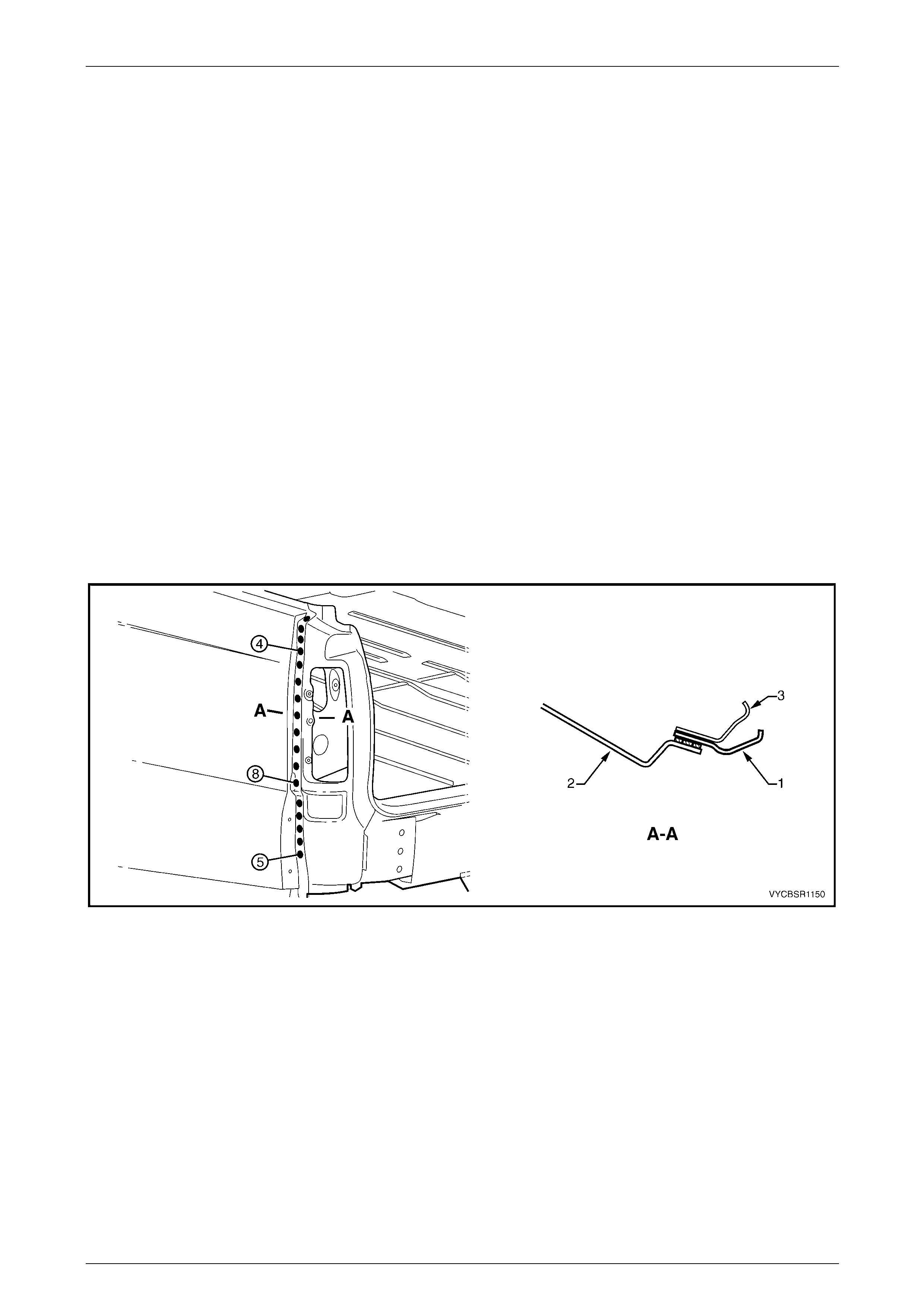
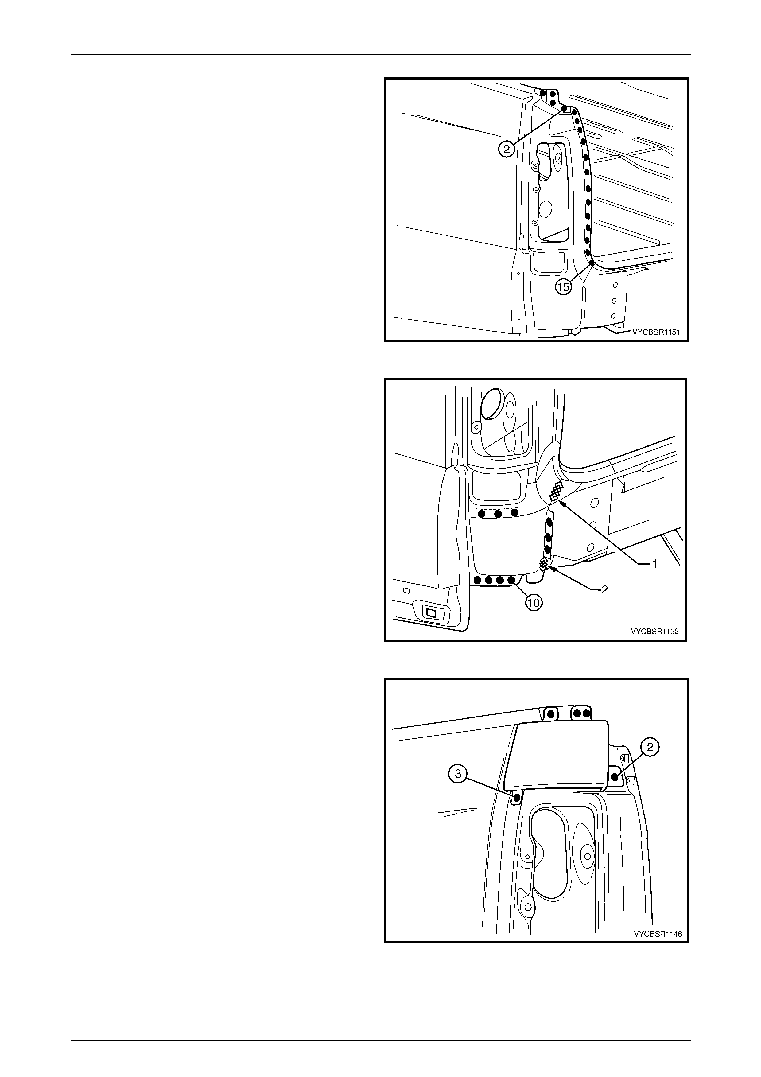
4 Clamp the panel into position, fitting the quarter panel extension flange (1) between the rear quarter panel (2) and
quarter inner lower rear extension (3), refer to Section A-A in Figure 1 1– 42 .
5 Test fit the tail lamp and check for correct alignment with the endgate and the body structure.
6 Spot or plug weld the quarter panel e xtensio n, rear quarter pan el and quarter inner lower rear extension.
Figure 11–42
Rear Tray Body Assembly, Crew Cab Page 11–26
Page 11–26
7 Spot or plug weld the quarter panel e xtensio n to the
inner side panel and quarter i nner lower rear
extension.
Figure 11–43
8 Spot or plug weld the quarter panel e xtensio n to the
rear end lower panel.
9 MIG weld two places (1 & 2), the quarter panel
extension to the rear end lower panel.
Figure 11–44
10 Install and spot or plug weld the quarter panel upper
extension.
11 Refinish and paint panels and other components as
required, refer to Section 3, 1.3 Paint Refinishing in
the MY 2003 VY and V2 Series Service Manual
Supplement, Body Structure Repair.
12 Apply Joint Sealer (Item 3) as required, refer to
Section 3B, 5 Body Sealing, Adhesives & Deadeners.
13 Apply Cavity Wax (Item 8) as required to the inside of
any box sections or areas inaccessible to paint, refer
to Section 3B, 6 Cavity Wax.
14 Install the remaining components as described in the
appropriate Section of the MY 2004 VY Regu lar Cab
and Crew Cab Service Information.
Figure 11–45

Rear Tray Body Assembly, Crew Cab Page 11–27
Page 11–27
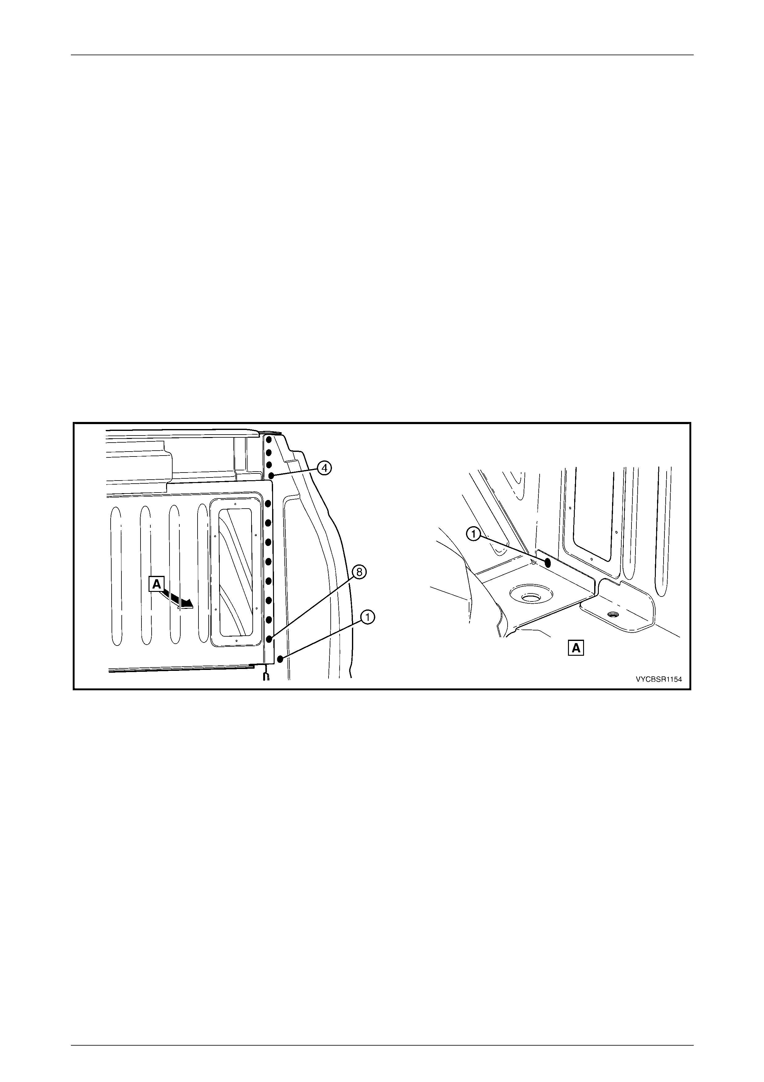
2.7 Quarter Panel Front Gusset – Replace
Remove
1 Remove the rear tray body assembly from the vehicle.
This is required to provide access to the welds. Refer
to Section 1B Sheetmetal in the MY 200 4 VY Regular
Cab and Crew Cab Service Information.
2 Remove the adjacent bolt-on panels a nd components
as described in the appropriate Section of the
MY 2004 VY Regular Cab and Crew Cab Service
Information.
3 Remove the rear quarter panel, refer to
2.4 Rear Quarter Panel – Replace.
4 Spot cut the welds attaching the quarter panel front
gusset to the inner side panel assembly, refer to
Figure 11–47. Figure 11–46
Figure 11–47
5 Remove the gusset noting that it is sandwiched between the front end panel and inner side panel assembly.
6 Repair any damage to adjacent parts as required.
7 Check and rectify the alignme nt of the body as required, refer to Section 3B, 3 Body Dimensions.
Rear Tray Body Assembly, Crew Cab Page 11–28
Page 11–28
Replace
NOTE
• Spot welding is the preferred method for
attaching of panels and should be used
whenever possible. Where the spot welding
equipment available will not access the
required weld position, a plug weld should be
performed.
• The same number and position of spot welds
(or plug welds) should be used when
replacing the panel, as was used during
manufacture, in order to maintain the original
structural strength of the vehicle.
1 As required, mark the new panel with drilling locations in preparation for plug welding. Drill holes as required.
2 Prepare all mating surfaces and treat with Weld Through Primer (Item 1) as required, refer to Section 3B,
5 Body Sealing, Adhesives & Dea deners.
3 Clamp the panel into position, ensuring it is located between the front end panel and inner side panel assembly.
4 Spot or plug weld the gusset to the front end panel and inner side panel assembly, refer to Figure 1 1– 48.
Figure 11–48
5 Reinstall the rear quarter panel, refer to 2.4 Rear Quarter Pane l – Replace.
6 Refinish and paint panels and other components as required, refer to Section 3, 1.3 Paint Refinishing in the MY
2003 VY and V2 Series Service Manual Supplement, Body Structure Repair.
7 Apply Joint Sealer (Item 3) as required, refer to Section 3B, 5 Body Sealing, Adhesives & Deadeners.
8 Apply Cavity Wax (Item 8) as required to the inside of any box sections or areas inaccessible to paint, refer to
Section 3B, 6 Cavity Wax.
9 Reinstall the rear tray body assembly, refer to Section 1B Sheetmetal in the MY 2004 VY Regular Cab and Crew
Cab Service Information.
10 Install the remaining compon ents as described in the appropriate Secti on of the MY 2004 VY Regular Cab and
Crew Cab Service Information.
Rear Tray Body Assembly, Crew Cab Page 11–29
Page 11–29
2.8 Quarter Inner Lower Rear Extension –
Replace
Remove
1 Remove the adjacent bolt-on panels a nd components
as described in the appropriate Section of the
MY 2004 VY Regular Cab and Crew Cab Service
Information.
2 Remove the quarter panel extension, refer to
2.6 Quarter Panel Extension – Replace.
Figure 11–49
3 Spot cut the welds attaching the quarter inner lower
rear extension to the side inner upper panel.
4 Remove the quarter inner lo wer rear extension and
repair any damage to adjacent parts as required.
Figure 11–50
Rear Tray Body Assembly, Crew Cab Page 11–30
Page 11–30
Replace
NOTE
• Spot welding is the preferred method for
attaching of panels and should be used
whenever possible. Where the spot welding
equipment available will not access the
required weld position, a plug weld should be
performed.
• The same number and position of spot welds
(or plug welds) should be used when
replacing the panel, as was used during
manufacture, in order to maintain the original
structural strength of the vehicle.
1 As required, mark the new panel with drilling locations in preparation for plug welding. Drill holes as required.
2 Prepare all mating surfaces and treat with Weld Through Primer (Item 1) as required, refer to Section 3B,
5 Body Sealing, Adhesives & Dea deners.
3 Clamp in position and spot or plug weld the quarter
inner lower rear extension to the inner side panel.
4 Replace the quarter panel extension, refer to
2.6 Quarter Panel Extension – Replace.
5 Refinish and paint panels and other components as
required, refer to Section 3, 1.3 Paint Refinishing in
the MY 2003 VY and V2 Series Service Manual
Supplement, Body Structure Repair.
6 Apply Joint Sealer (Item 3) as required, refer to
Section 3B, 5 Body Sealing, Adhesives & Deadeners.
7 Apply Cavity Wax (Item 8) as required to the inside of
any box sections or areas inaccessible to paint, refer
to Section 3B, 6 Cavity Wax.
8 Install the remaining components as described in the
appropriate Section of the MY 2004 VY Regu lar Cab
and Crew Cab Service Information.
Figure 11–51
Rear Tray Body Assembly, Crew Cab Page 11–31
Page 11–31
2.9 Quarter Panel Rear Brace – Replace
Remove
1 Remove the adjacent bolt-on panels a nd components
as described in the appropriate Section of the
MY 2004 VY Regular Cab and Crew Cab Service
Information.
2 Remove the adjacent panels as required, refer to the
appropriate procedure in this Section.
Figure 11–52
3 If the quarter panel extension is not remove d, spot cut
the welds attaching quarter panel rear brace to the
extension.
Figure 11–53
4 Spot cut the welds attaching the quarter panel rear
brace to the inner side panel.
5 Remove the quarter panel rear brace from the vehicle
and then repair any damage t o adjacent parts as
required.
Figure 11–54

Rear Tray Body Assembly, Crew Cab Page 11–32
Page 11–32
Replace
NOTE
• Spot welding is the preferred method for
attaching of panels and should be used
whenever possible. Where the spot welding
equipment available will not access the
required weld position, a plug weld should be
performed.
• The same number and position of spot welds
(or plug welds) should be used when
replacing the panel, as was used during
manufacture, in order to maintain the original
structural strength of the vehicle.
1 As required, mark the new panel with drilling locations in preparation for plug welding. Drill holes as required.
2 Prepare all mating surfaces and treat with Weld Through Primer (Item 1) as required, refer to Section 3B,
5 Body Sealing, Adhesives & Dea deners.
3 Spot or plug weld the quarter panel rear brace to the
inner side panel.
Figure 11–55
4 If the quarter panel extension is not remove d, spot or
plug weld the quarter panel rear brace to the
extension.
5 Replace any other remov ed panels as required.
6 Refinish and paint panels and other components as
required, refer to Section 3, 1.3 Paint Refinishing in
the MY 2003 VY and V2 Series Service Manual
Supplement, Body Structure Repair.
7 Apply Joint Sealer (Item 3) as required, refer to
Section 3B, 5 Body Sealing, Adhesives & Deadeners.
8 Apply Cavity Wax (Item 8) as required to the inside of
any box sections or areas inaccessible to paint, refer
to Section 3B, 6 Cavity Wax.
9 Install the remaining components as described in the
appropriate Section of the MY 2004 VY Regu lar Cab
and Crew Cab Service Information.
Figure 11–56
Rear Tray Body Assembly, Crew Cab Page 11–33
Page 11–33
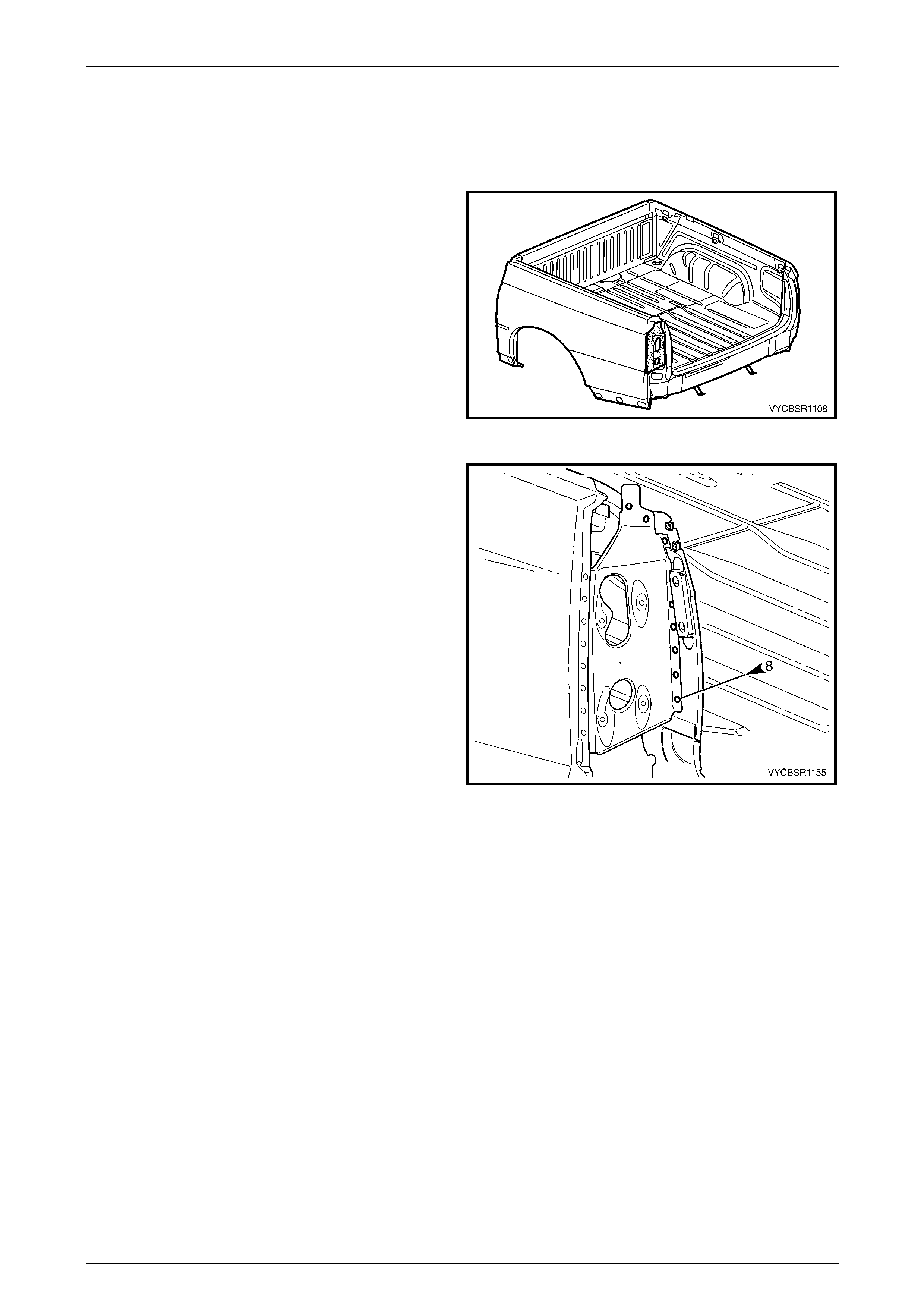
2.10 Quarter Lower Rear Panel – Replace
Remove
1 Remove the adjacent bolt-on panels a nd components
as described in the appropriate Section of the
MY 2004 VY Regular Cab and Crew Cab Service
Information.
2 Remove the adjacent panels as required, refer to the
appropriate procedure in this Section.
Figure 11–57
3 Spot cut the welds attaching the quarter lower rear
panel to the rear tray body assembly.
4 Carefully grind the MIG weld along the quarter lower
rear panel and rear end lower panel join.
Figure 11–58
5 Spot cut the welds attaching the quarter lower rear
panel to the side inner upper panel.
6 Carefully grind the MIG weld along the quarter lower
rear panel and inner side p an el join.
7 Remove the panel from the vehicle, then repair any
damage to adjacent parts as required.
Figure 11–59
Rear Tray Body Assembly, Crew Cab Page 11–34
Page 11–34
Replace
NOTE
• Spot welding is the preferred method for
attaching of panels and should be used
whenever possible. Where the spot welding
equipment available will not access the
required weld position, a plug weld should be
performed.
• The same number and position of spot welds
(or plug welds) should be used when
replacing the panel, as was used during
manufacture, in order to maintain the original
structural strength of the vehicle.
1 As required, mark the new panel with drilling locations in preparation for plug welding. Drill holes as required.
2 Prepare all mating surfaces and treat with Weld Through Primer (Item 1) as required, refer to Section 3B,
5 Body Sealing, Adhesives & Dea deners.
3 Spot or plug weld, the quarter lower rear panel to the
inner side panel.
Figure 11–60
4 Spot or plug weld the quarter lo wer rear panel to the
rear tray body assembly.
5 MIG weld along the quarter lower rear panel, side
inner upper panel and rear en d panel join.
6 Replace any other remov ed panels as required.
7 Refinish and paint panels and other components as
required, refer to Section 3, 1.3 Paint Refinishing in
the MY 2003 VY and V2 Series Service Manual
Supplement, Body Structure Repair.
8 Apply Joint Sealer (Item 3) as required, refer to
Section 3B, 5 Body Sealing, Adhesives & Deadeners.
9 Apply Cavity Wax (Item 8) as required to the inside of
any box sections or areas inaccessible to paint, refer
to Section 3B, 6 Cavity Wax.
10 Install the remaining components as described in the
appropriate Section of the MY 2004 VY Regu lar Cab
and Crew Cab Service Information.
Figure 11–61
Rear Tray Body Assembly, Crew Cab Page 11–35
Page 11–35
2.11 Inner Side Panel – Replace
NOTE
This procedure also includes the cargo tie-down
brackets.
Remove
1 Remove the adjacent bolt-on panels a nd components
as described in the appropriate Section of the
MY 2004 VY Regular Cab and Crew Cab Service
Information.
2 Remove the adjacent panels as required, refer to the
relevant Section in this Supplement.
3 Remove the welds attaching the inner sid e p anel to
the quarter rear lower panel, refer to
2.10 Quarter Lower Rear Panel – Replace
Figure 11–62
4 Spot cut the welds and grind off the MIG welds (1), attaching the left-hand or right-hand inner side panel to the load
floor panel, refer to Figure 11–63.
Figure 11–63
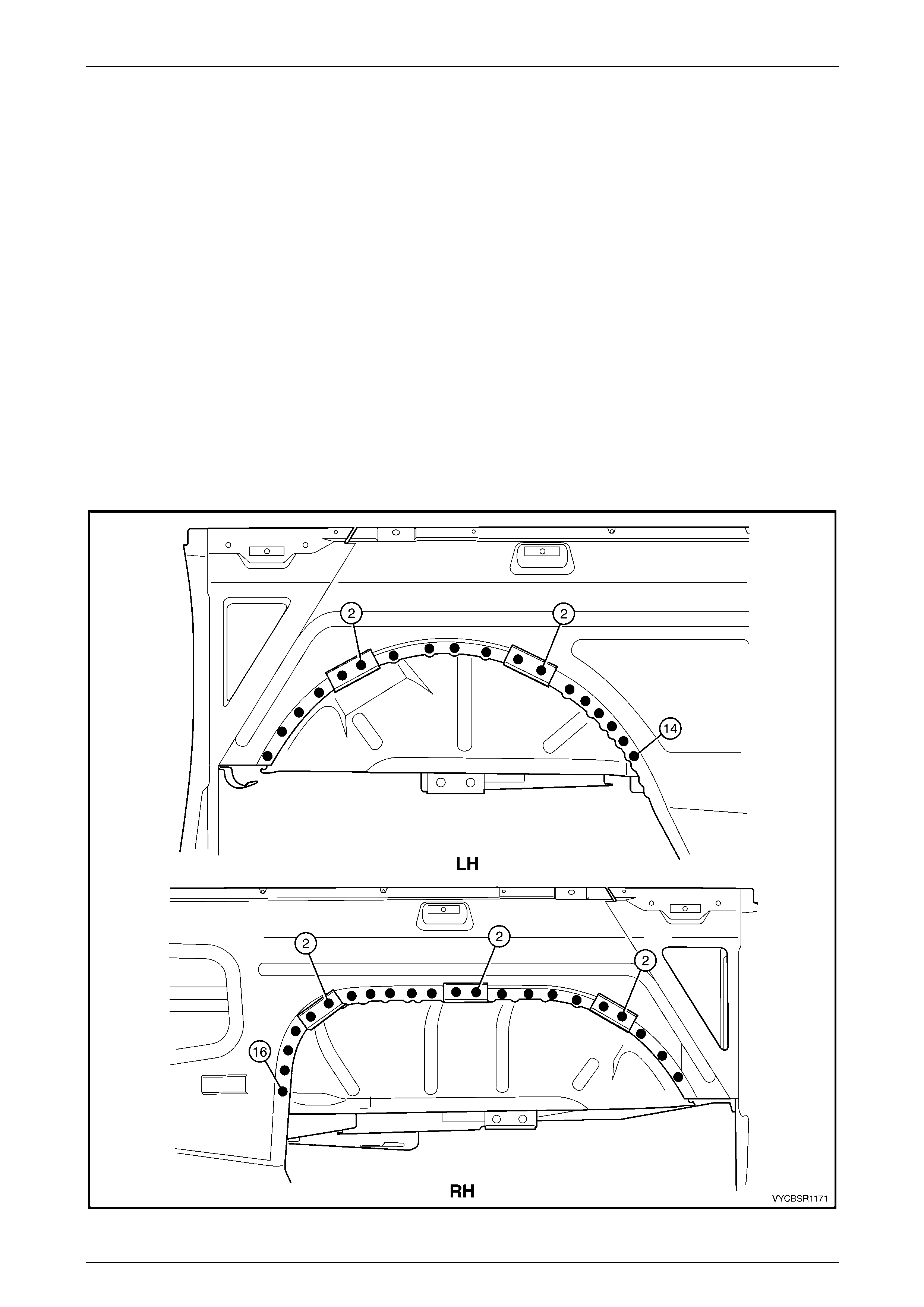
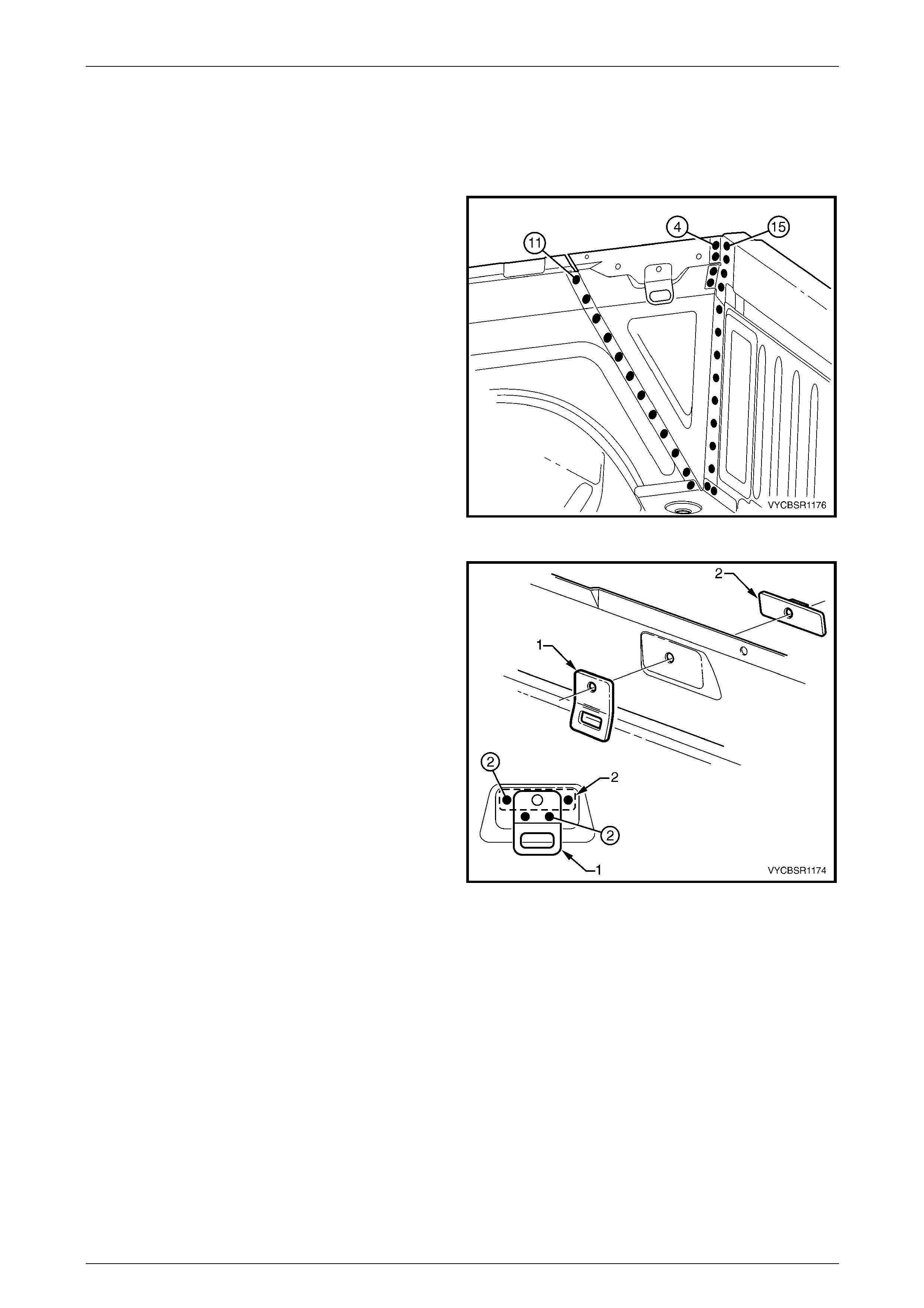
5 Spot cut the welds attaching the inner side panel to
the inner side panel extension and l oad floor panel
front extension.
6 Spot cut the welds attaching the inner side panel to
the rear wheelhouse inner pa nel, refer to
Figure 11–65.
NOTE
During this procedur e the wheel hous e filler pan el
brackets are also removed.
7 Remove the panel from the vehicle, then repair any
damage to adjacent parts as required.
Figure 11–64
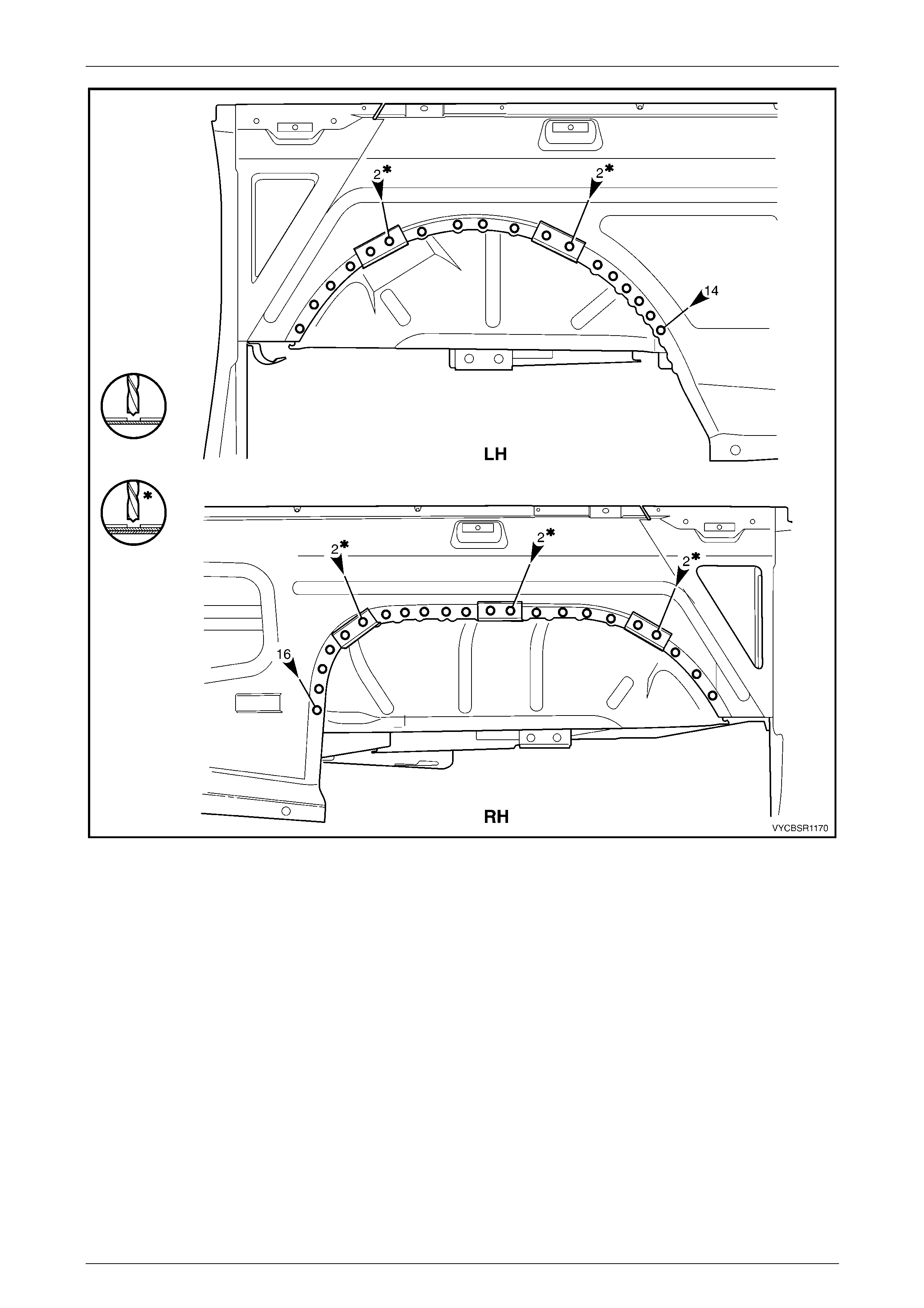
Rear Tray Body Assembly, Crew Cab Page 11–36
Page 11–36
Figure 11–65
Rear Tray Body Assembly, Crew Cab Page 11–37
Page 11–37
Replace
NOTE
• Spot welding is the preferred method for
attaching of panels and should be used
whenever possible. Where the spot welding
equipment available will not access the
required weld position, a plug weld should be
performed.
• The same number and position of spot welds
(or plug welds) should be used when
replacing the panel, as was used during
manufacture, in order to maintain the original
structural strength of the vehicle.
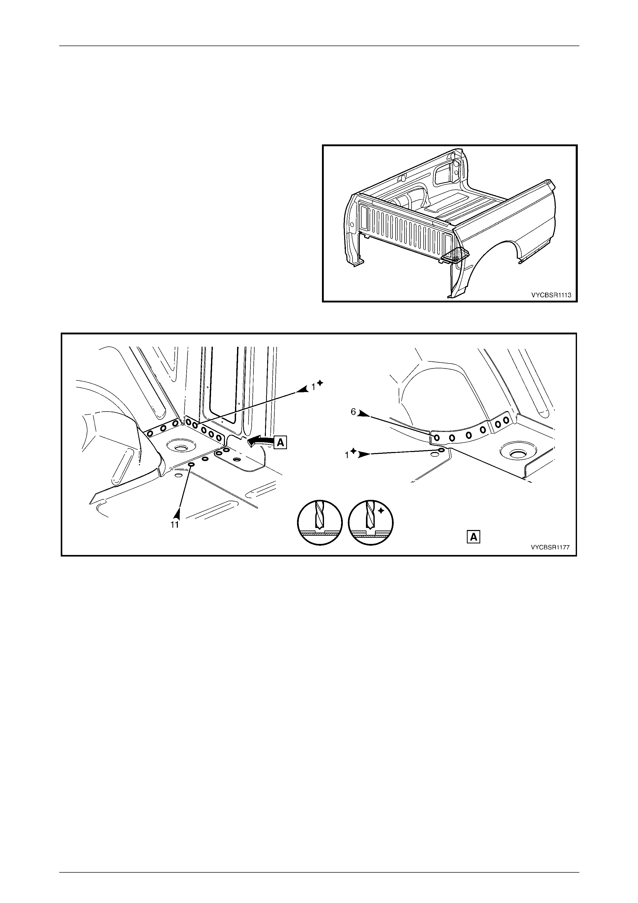
1 As required, mark the new panel with drilling locations in preparation for plug welding. Drill holes as required.
2 Prepare all mating surfaces and treat with Weld Through Primer (Item 1) as required, refer to Section 3B,
5 Body Sealing, Adhesives & Dea deners.
3 Clamp the new panel and the wheelhouse filler panel brackets in position.
4 Spot or plug weld the inner side pa nel and wheelhouse filler panel brackets to the rear wheelhouse inner panel,
refer to Figure 11–66.
Figure 11–66
Rear Tray Body Assembly, Crew Cab Page 11–38
Page 11–38
5 Spot or plug weld the inner side pane l to the inner side
panel extension and load floor panel front extension.
6 Spot or plug weld the inner side pane l to the load floor
panel, refer to Figure 11–68.
7 MIG weld (1) the right-hand or left-hand side inner
upper panel to the load floor panel.
Figure 11–67
Figure 11–68
8 Spot or plug weld the inner side pane l to the quarter lower rear panel, refer to
2.10 Quarter Lower Rear Panel – Replace.
Rear Tray Body Assembly, Crew Cab Page 11–39
Page 11–39
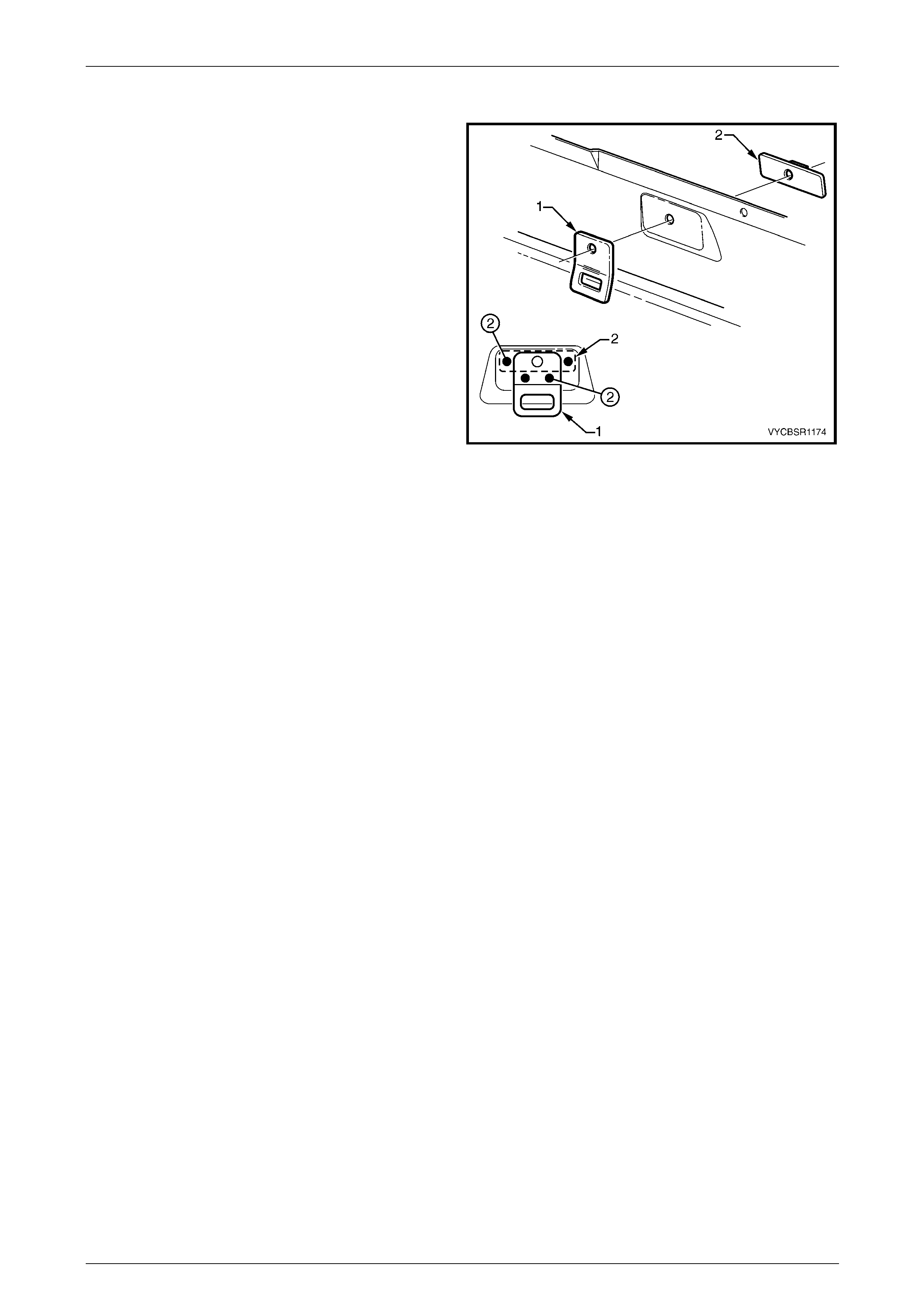
9 As required, clamp the cargo tie-down bracket (1) and
the cargo tie-down bracket anchor pl ate (2) to the side
inner upper panel.
10 Spot or plug weld the anchor plate and the tie-down
bracket to the inner side panel, two places each.
11 Repeat for the other bracket as required.
12 Clean up and prime all areas that will be covered by
any other removed panels.
13 Install any other removed pan els as req uire d, refer to
the appropriate Section of this Supplement.
14 Refinish and paint panels and other components as
required, refer to Section 3, 1.3 Paint Refinishing in
the MY 2003 VY and V2 Series Service Manual
Supplement, Body Structure Repair.
15 Apply Joint Sealer (Item 3) as required, refer to
Section 3B, 5 Body Sealing, Adhesives & Deadeners. Figure 11–69
16 Apply Cavity Wax (Item 8) as required to the inside of any box sections or areas inaccessible to paint, refer to
Section 3B, 6 Cavity Wax.
17 Apply Spray-on Dea de ner (Item 7) to the wheel side of the rear wheelhouse as required, refer to Section 3B,
5 Body Sealing, Adhesives & Dea deners.
18 Install the remaining compon ents as described in the appropriate Secti on of the MY 2004 VY Regular Cab and
Crew Cab Service Information.
Rear Tray Body Assembly, Crew Cab Page 11–40
Page 11–40
2.12 Inner Side Panel Extension Assembly –
Replace
NOTE
This procedure also includes the cargo tie-down
bracket.
Remove
1 Remove the adjacent bolt-on panels a nd components
as described in the appropriate Section of the
MY 2004 VY Regular Cab and Crew Cab Service
Information.
2 Remove the adjacent panels as required, refer to the
relevant Section in this Supplement.
Figure 11–70
3 As required, spot cut the welds attaching the inner
side panel extension assembly to the rear tray body
assembly.
4 Remove the panel from the vehicle and th en repair
any damage to adjacent parts as required.
Figure 11–71
Replace
NOTE
• Spot welding is the preferred method for
attaching of panels and should be used
whenever possible. Where the spot welding
equipment available will not access the
required weld position, a plug weld should be
performed.
• The same number and position of spot welds
(or plug welds) should be used when
replacing the panel, as was used during
manufacture, in order to maintain the original
structural strength of the vehicle.
Rear Tray Body Assembly, Crew Cab Page 11–41
Page 11–41
1 As required, mark the new panel with drilling locations in preparation for plug welding. Drill holes as required.
2 Prepare all mating surfaces and treat with Weld Through Primer (Item 1) as required, refer to Section 3B,
5 Body Sealing, Adhesives & Dea deners.
3 Clamp the new panel in position.
4 Spot or plug weld the inner side pa nel extension
assembly to the rear tray body assembly as required.
Figure 11–72
5 As required, clamp the cargo tie-down bracket (1) and
the cargo tie-down bracket anchor pl ate (2) to the side
inner upper panel.
6 Spot or plug weld the anchor plate and the tie-down
bracket to the inner side panel, two places each.
7 Clean up and prime all ar eas that will be covered by
any other removed panels.
8 Install any other removed pan els as req uire d, refer to
the appropriate Section of this Supplement.
9 Refinish and paint panels and other components as
required, refer to Section 3, 1.3 Paint Refinishing in
the MY 2003 VY and V2 Series Service Manual
Supplement, Body Structure Repair.
10 Apply Joint Sealer (Item 3) as required, refer to
Section 3B, 5 Body Sealing, Adhesives & Deadeners.
11 Apply Cavity Wax (Item 8) as required to the inside of
any box sections or areas inaccessible to paint, refer
to Section 3B, 6 Cavity Wax. Figure 11–73
12 Apply Spray-on Dea de ner (Item 7) to the wheel side of the rear wheelhouse as required, refer to Section 3B,
5 Body Sealing, Adhesives & Dea deners.
13 Install the remaining compon ents as described in the appropriate Secti on of the MY 2004 VY Regular Cab and
Crew Cab Service Information.
Rear Tray Body Assembly, Crew Cab Page 11–42
Page 11–42
2.13 Load Floor Panel Front Extension –
Replace
Remove
1 Remove the adjacent bolt-on panels a nd components
as described in the appropriate Section of the
MY 2004 VY Regular Cab and Crew Cab Service
Information.
2 Remove the adjacent panels as required, refer to the
relevant Section in this Supplement.
3 Spot cut the welds attaching the load floor panel front
extension to rear tray body assembly as required, refer
to Figure 11–75.
4 Remove the load floor panel front extension and then
repair any damage to adjacent parts as required.
Figure 11–74
Figure 11–75
Rear Tray Body Assembly, Crew Cab Page 11–43
Page 11–43
Replace
NOTE
• Spot welding is the preferred method for
attaching of panels and should be used
whenever possible. Where the spot welding
equipment available will not access the
required weld position, a plug weld should be
performed.
• The same number and position of spot welds
(or plug welds) should be used when
replacing the panel, as was used during
manufacture, in order to maintain the original
structural strength of the vehicle.
1 As required, mark the new panel with drilling locations in preparation for plug welding. Drill holes as required.
2 Prepare all mating surfaces and treat with Weld Through Primer (Item 1) as required, refer to Section 3B,
5 Body Sealing, Adhesives & Dea deners.
3 Clamp the load floor panel front exte nsion in position and spot or plug weld to the rear tray body assembly as
required, refer to Figure 11–76.
Figure 11–76
4 Install any other removed pan els as required, refer to the appropriate Section of this Supplement.
5 Refinish and paint panels and other components as required, refer to Section 3, 1.3 Paint Refinishing in the MY
2003 VY and V2 Series Service Manual Supplement, Body Structure Repair.
6 Apply Joint Sealer (Item 3) as required, refer to Section 3B, 5 Body Sealing, Adhesives & Deadeners.
7 Apply Cavity Wax (Item 8) as required to the inside of any box sections or areas inaccessible to paint, refer to
Section 3B, 6 Cavity Wax.
8 Install the remaining components as described in the appropriate Section of the MY 2004 VY Regular Cab and
Crew Cab Service Information.
Rear Tray Body Assembly, Crew Cab Page 11–44
Page 11–44
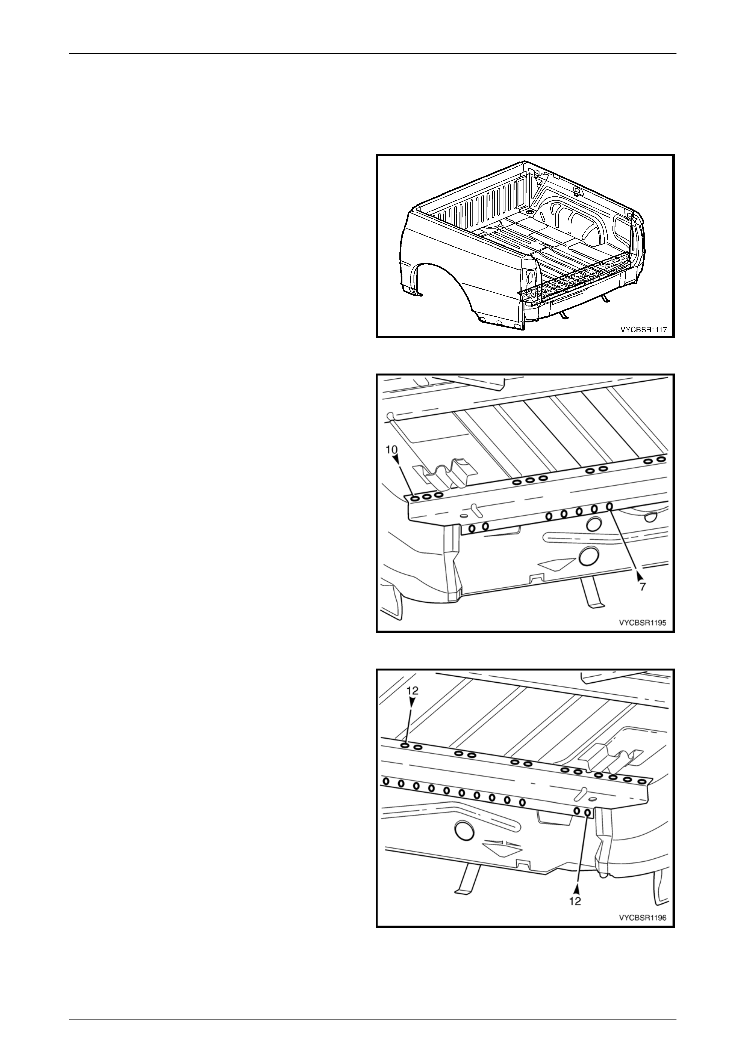
2.14 Rear Wheelhouse Inner Panel – Replace
1 Remove the adjacent bolt-on panels a nd components
as described in the appropriate Section of the
MY 2004 VY Regular Cab and Crew Cab Service
Information.
2 Remove the adjacent panels as required, refer to the
relevant Section in this Supplement.
Figure 11–77
Left-hand
Remove
1 Spot cut the welds attaching the rear wheelhouse inn er pan el to the load floor panel assembly, refer to
Figure 11–78.
2 Grind off the MIG welds (1), attaching the rear wheelhouse inner panel to the lo ad floor panel assembly.
Figure 11–78
Rear Tray Body Assembly, Crew Cab Page 11–45
Page 11–45
3 Spot cut the welds attaching the rear wheelhouse
inner panel to the load floor panel assembly from
underneath the rear tray body assembly.
4 Spot cut the welds attaching the rear wheelhouse
inner panel to the inner side panel, refer to
Figure 11–80.
5 Remove the rear wheelhouse inner panel and then
repair any damage to adjacent parts as required.
Figure 11–79
Figure 11–80
Rear Tray Body Assembly, Crew Cab Page 11–46
Page 11–46
Replace
NOTE
• Spot welding is the preferred method for
attaching of panels and should be used
whenever possible. Where the spot welding
equipment available will not access the
required weld position, a plug weld should be
performed.
• The same number and position of spot welds
(or plug welds) should be used when
replacing the panel, as was used during
manufacture, in order to maintain the original
structural strength of the vehicle.
1 As required, mark the new panel with drilling locations in preparation for plug welding. Drill holes as required.
2 Prepare all mating surfaces and treat with Weld Through Primer (Item 1) as required, refer to Section 3B,
5 Body Sealing, Adhesives & Dea deners.
3 Spot or plug weld the rear wheelhouse inner panel to the inner side panel, refer to Figure 11–81.
Figure 11–81
4 Spot or plug weld the rear wheelhouse inner panel to the load floor panel assemb ly, refer to Figure 11–82.
5 MIG weld (1) the rear wheelhouse inner panel to the load floor panel assembly.
Figure 11–82
Rear Tray Body Assembly, Crew Cab Page 11–47
Page 11–47
6 Spot or plug weld the rear wheelhouse inner panel to
the load floor panel assembly from under neath the
rear tray body assembly.
7 Install any other removed pan els as req uire d, refer to
the appropriate Section of this Supplement.
8 Refinish and paint panels and other components as
required, refer to Section 3, 1.3 Paint Refinishing in
the MY 2003 VY and V2 Series Service Manual
Supplement, Body Structure Repair.
9 Apply Joint Sealer (Item 3) as required, refer to
Section 3B, 5 Body Sealing, Adhesives & Deadeners.
10 Apply Cavity Wax (Item 8) as required to the inside of
any box sections or areas inaccessible to paint, refer
to Section 3B, 6 Cavity Wax.
11 Apply Spray-o n deadener to the wheel side of the rear
wheelhouse panel, refer to Section 3B,
5. Body Sealing, Adhesives & Dead eners.
12 Install the remaining components as described in the
appropriate Section of the MY 2004 VY Regu lar Cab
and Crew Cab Service Information.
Figure 11–83
Right-hand
Remove
1 Spot cut the welds attaching the rear wheelhouse inn er pan el to the load floor panel assembly, refer to
Figure 11–84.
2 Grind off the MIG welds (1) attaching the rear wheelhouse inner panel to the load floor panel assembly.
Figure 11–84
Rear Tray Body Assembly, Crew Cab Page 11–48
Page 11–48
3 Spot cut the welds attaching the rear wheelhouse
inner panel to the load floor panel assembly from
underneath the rear tray body assembly.
4 Spot cut the welds attaching the rear wheelhouse
inner panel to the inner side panel, refer to
Figure 11–86.
5 Remove the rear wheelhouse inner panel and then
repair any damage to adjacent parts as required.
Figure 11–85
Figure 11–86
Rear Tray Body Assembly, Crew Cab Page 11–49
Page 11–49
Replace
NOTE
• Spot welding is the preferred method for
attaching of panels and should be used
whenever possible. Where the spot welding
equipment available will not access the
required weld position, a plug weld should be
performed.
• The same number and position of spot welds
(or plug welds) should be used when
replacing the panel, as was used during
manufacture, in order to maintain the original
structural strength of the vehicle.
1 As required, mark the new panel with drilling locations in preparation for plug welding. Drill holes as required.
2 Prepare all mating surfaces and treat with Weld Through Primer (Item 1) as required, refer to Section 3B,
5 Body Sealing, Adhesives & Dea deners.
3 Spot or plug weld the rear wheelhouse inner panel to the inner side panel, refer to Figure 11–87.
Figure 11–87
4 Spot or plug weld the rear wheelhouse inner panel to the load floor panel assemb ly, refer to Figure 11–88.
5 MIG weld (1) the rear wheelhouse inner panel to the load floor panel assembly.
Rear Tray Body Assembly, Crew Cab Page 11–50
Page 11–50
Figure 11–88
6 Spot or plug weld the rear wheelhouse inner panel to
the load floor panel assembly from under neath the
rear tray body assembly.
7 Install any other removed pan els as req uire d, refer to
the appropriate Section of this Supplement.
8 Refinish and paint panels and other components as
required, refer to Section 3, 1.3 Paint Refinishing in
the MY 2003 VY and V2 Series Service Manual
Supplement, Body Structure Repair.
9 Apply Joint Sealer (Item 3) as required, refer to
Section 3B, 5 Body Sealing, Adhesives & Deadeners.
10 Apply Cavity Wax (Item 8) as required to the inside of
any box sections or areas inaccessible to paint, refer
to Section 3B, 6 Cavity Wax.
11 Apply Spray-o n deadener to the wheel side of the rear
wheelhouse panel, refer to Section 3B,
5. Body Sealing, Adhesives & Dead eners.
12 Install the remaining components as described in the
appropriate Section of the MY 2004 VY Regu lar Cab
and Crew Cab Service Information.
Figure 11–89
Rear Tray Body Assembly, Crew Cab Page 11–51
Page 11–51
2.15 Front End Panel Sill Assembly – Replace
NOTE
This procedure also includes the front cover
attachment beam.
Remove
1 Remove the adjacent bolt-on panels a nd components
as described in the appropriate Section of the
MY 2004 VY Regular Cab and Crew Cab Service
Information.
2 Remove the adjacent panels as required, refer to the
relevant Section in this Supplement.
3 From each side of the rear tray body assembly, spot
cut the welds attaching the front end sill panel
assembly, refer to Figure 11–91.
NOTE
• If the front cover attachment beam is not
being removed with the front end sill panel
assembly, spot cut the inner welds shown A.
• If the front cover attachment beam is to be
removed with the front end sill panel
assembly, spot cut the inner welds shown B.
Figure 11–90
Figure 11–91
4 Remove the front end sill panel assem bly and then repair any damage to adjacent parts as required.
Rear Tray Body Assembly, Crew Cab Page 11–52
Page 11–52
Replace
NOTE
• Spot welding is the preferred method for
attaching of panels and should be used
whenever possible. Where the spot welding
equipment available will not access the
required weld position, a plug weld should be
performed.
• The same number and position of spot welds
(or plug welds) should be used when
replacing the panel, as was used during
manufacture, in order to maintain the original
structural strength of the vehicle.
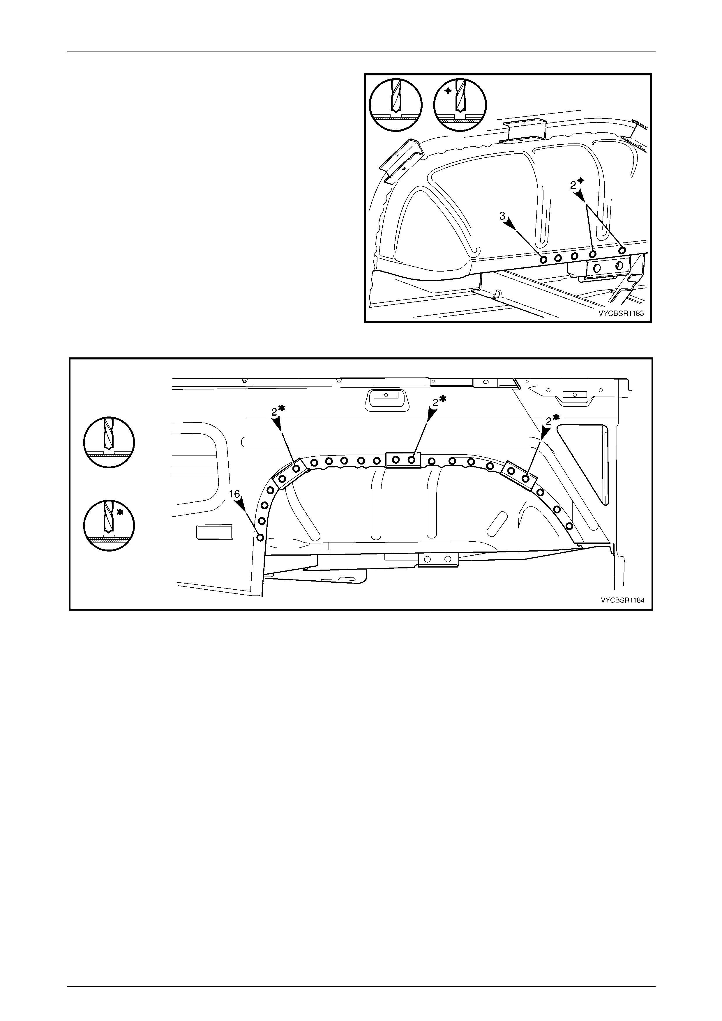
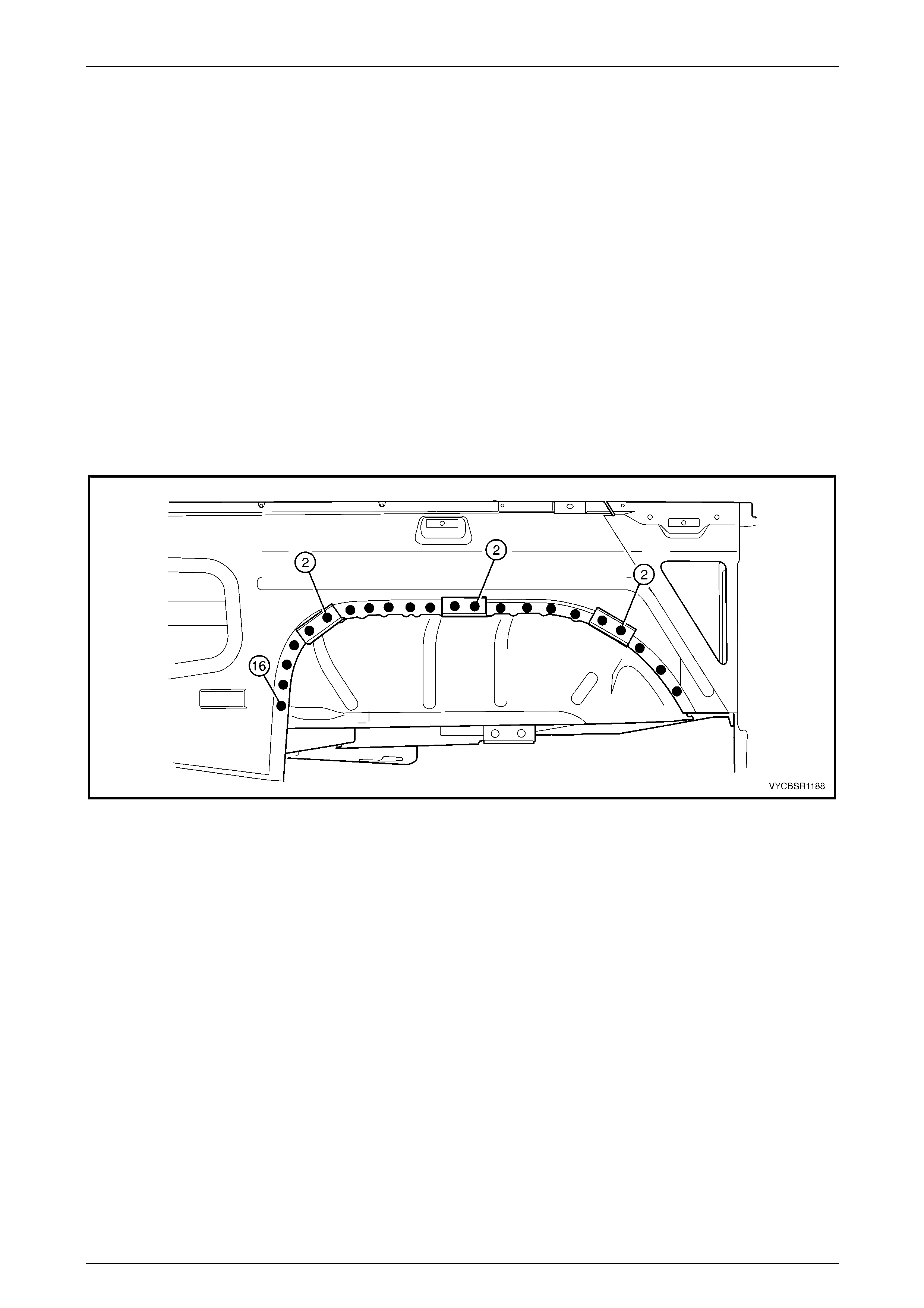
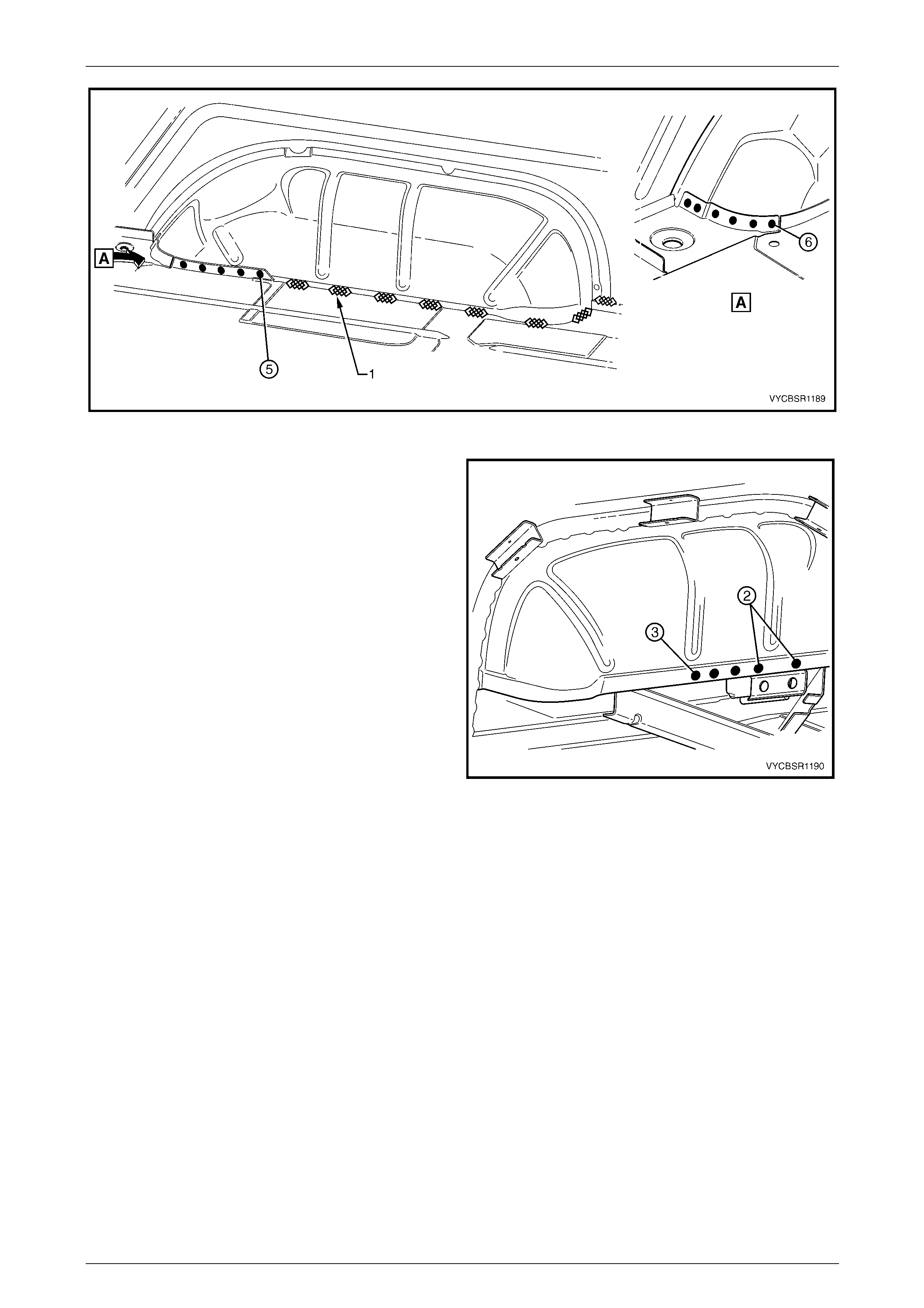
1 As required, mark the new panel with drilling locations in preparation for plug welding. Drill holes as required.
2 Prepare all mating surfaces and treat with Weld Through Primer (Item 1) as required, refer to Section 3B,
5 Body Sealing, Adhesives & Dea deners.
3 Clamp the new front end sill panel assembly and, if removed, the front cover attachment beams in position,
ensuring the front end panel is seated between the sill panel and re inforcement.
4 Spot or plug weld the panels as required, ref er to F igure 11–92.
Figure 11–92
5 Install any other removed pan els as required, refer to the appropriate Section of this Supplement.
6 Refinish and paint panels and other components as required, refer to Section 3, 1.3 Paint Refinishing in the MY
2003 VY and V2 Series Service Manual Supplement, Body Structure Repair.
7 Apply Joint Sealer (Item 3) as required, refer to Section 3B, 5 Body Sealing, Adhesives & Deadeners.
8 Apply Cavity Wax (Item 8) as required to the inside of any box sections or areas inaccessible to paint, refer to
Section 3B, 6 Cavity Wax.
9 Apply Spray-on Dea de ner (Item 7) to the wheel side of the rear wheelhouse as required, refer to Section 3B,
5 Body Sealing, Adhesives & Dea deners.
10 Install the remaining compon ents as described in the appropriate Secti on of the MY 2004 VY Regular Cab and
Crew Cab Service Information.
Rear Tray Body Assembly, Crew Cab Page 11–53
Page 11–53
2.16 Front End Panel – Replace
Remove
1 Remove the rear tray body assembly from the vehicle,
refer to Section 1B Sheetmetal in the MY 2004 VY
Regular Cab and Crew Cab S ervice Information.
2 Remove the adjacent bolt-on panels a nd components
as described in the appropriate Section of the
MY 2004 VY Regular Cab and Crew Cab Service
Information.
3 Remove the adjacent panels as required, refer to the
relevant Section in this Supplement.
4 From each side of the rear tray body assembly, spot
cut the welds attaching the front end panel, refer to
Figure 11–94.
NOTE
It may be required to grind the MIG weld (1)
attaching front end panel locator.
Figure 11–93
Figure 11–94
5 Remove the front end panel and then repair any damage to adjacent parts as requir ed.
Rear Tray Body Assembly, Crew Cab Page 11–54
Page 11–54
Replace
NOTE
• Spot welding is the preferred method for
attaching of panels and should be used
whenever possible. Where the spot welding
equipment available will not access the
required weld position, a plug weld should be
performed.
• The same number and position of spot welds
(or plug welds) should be used when
replacing the panel, as was used during
manufacture, in order to maintain the original
structural strength of the vehicle.
1 As required, mark the new panel with drilling locations in preparation for plug welding. Drill holes as required.
2 Prepare all mating surfaces and treat with Weld Through Primer (Item 1) as required, refer to Section 3B,
5 Body Sealing, Adhesives & Dea deners.
3 Clamp the new front end panel in pos ition, ensuring it is seated between the sill pane l and reinforcement.
4 Spot or plug weld the panel, refer to Figure 11–95.
NOTE
It may be required to MIG weld (1) the front end
panel locator.
Figure 11–95
5 Install any other removed pan els as required, refer to the appropriate Section of this Supplement.
6 Refinish and paint panels and other components as required, refer to Section 3, 1.3 Paint Refinishing in the MY
2003 VY and V2 Series Service Manual Supplement, Body Structure Repair.
7 Apply Joint Sealer (Item 3) as required, refer to Section 3B, 5 Body Sealing, Adhesives & Deadeners.
8 Apply Cavity Wax (Item 8) as required to the inside of any box sections or areas inaccessible to paint, refer to
Section 3B, 6 Cavity Wax.
9 Apply Spray-on Dea de ner (Item 7) to the wheel side of the rear wheelhouse as required, refer to Section 3B,
5 Body Sealing, Adhesives & Dea deners.
10 Reinstall the rear tray body assembly, refer to Section 1B Sheetmetal in the MY 2004 VY Regular Cab and Crew
Cab Service Information.
11 Install the remaining compon ents as described in the appropriate Secti on of the MY 2004 VY Regular Cab and
Crew Cab Service Information.
Rear Tray Body Assembly, Crew Cab Page 11–55
Page 11–55
2.17 Load Floor Panel Rear Support –
Replace
Remove
1 Remove the adjacent bolt-on panels a nd components
as described in the appropriate Section of the
MY 2004 VY Regular Cab and Crew Cab Service
Information.
2 Remove the adjacent panels as required, refer to the
relevant Section in this Supplement.
Figure 11–96
3 From underneath the vehicle, as required, spot cut the
welds attaching the right-hand side of the load floor
panel rear support.
Figure 11–97
4 From underneath the vehicle, as required, spot cut the
welds attaching the left-hand side of the l oad floor
panel rear support.
5 Remove the load floor panel r ear support and repair
any damage to adjacent parts as required.
Figure 11–98

Rear Tray Body Assembly, Crew Cab Page 11–56
Page 11–56
Replace
NOTE
• Spot welding is the preferred method for
attaching of panels and should be used
whenever possible. Where the spot welding
equipment available will not access the
required weld position, a plug weld should be
performed.
• The same number and position of spot welds
(or plug welds) should be used when
replacing the panel, as was used during
manufacture, in order to maintain the original
structural strength of the vehicle.
1 As required, mark the new panel with drilling locations in preparation for plug welding. Drill holes as required.
2 Prepare all mating surfaces and treat with Weld Through Primer (Item 1) as required, refer to Section 3B,
5 Body Sealing, Adhesives & Dea deners.
3 Clamp the load floor panel rear support in position.
4 From underneath the vehicle, as required, spot or plug
weld the right-hand side of the load floor panel rear
support.
Figure 11–99
5 From underneath the vehicle, as required, spot or plug
weld the left-hand side of the load floor panel rear
support.
6 Install any removed panels as required, refer to the
appropriate Section in this Supplement.
7 Refinish and paint panels and other components as
required, refer to Section 3, 1.3 Paint Refinishing in
the MY 2003 VY and V2 Series Service Manual
Supplement, Body Structure Repair.
8 Apply Joint Sealer (Item 3) as required, refer to
Section 3B, 5 Body Sealing, Adhesives & Deadeners.
9 Apply Cavity Wax (Item 8) as required to the inside of
any box sections or areas inaccessible to paint, refer
to Section 3B, 6 Cavity Wax.
10 Install the remaining components as described in the
appropriate Section of the MY 2004 VY Regu lar Cab
and Crew Cab Service Information. Figure 11–100
Rear Tray Body Assembly, Crew Cab Page 11–57
Page 11–57
2.18 Load Floor Panel Locator Guide –
Replace
Remove
1 Remove the rear tray body assembly from the vehicle,
refer to Section 1B Sheetmetal in the MY 2004 VY
Regular Cab and Crew Cab S ervice Information.
2 Remove the adjacent bolt-on panels a nd components
as described in the appropriate Section of the
MY 2004 VY Regular Cab and Crew Cab Service
Information.
3 From underneath the rear tray body assembly, spot
cut the welds attaching either the left-hand or right-
hand load floor panel locator guide, refer to
Figure 11–102.
Figure 11–101
Figure 11–102
4 Remove the load floor panel locator guide and repair any damage to adjacent parts as requ ired.
Rear Tray Body Assembly, Crew Cab Page 11–58
Page 11–58
Replace
NOTE
• Spot welding is the preferred method for
attaching of panels and should be used
whenever possible. Where the spot welding
equipment available will not access the
required weld position, a plug weld should be
performed.
• The same number and position of spot welds
(or plug welds) should be used when
replacing the panel, as was used during
manufacture, in order to maintain the original
structural strength of the vehicle.
1 As required, mark the new panel with drilling locations in preparation for plug welding. Drill holes as required.
2 Prepare all mating surfaces and treat with Weld Through Primer (Item 1) as required, refer to Section 3B,
5 Body Sealing, Adhesives & Dea deners.
3 Clamp the load floor panel locator guide in position, aligning it to the correct dimensions, refer to
3 Underfloor Component Location Dimensions.
4 From underneath the vehicle, spot or plug weld either the left-hand or right-hand load flo or pan el locator guide,
refer to Figure 11–103.
Figure 11–103
5 Install any removed panels as required, refer to the appropriate Section in this Supplement.
6 Refinish and paint panels and other components as required, refer to Section 3, 1.3 Paint Refinishing in the MY
2003 VY and V2 Series Service Manual Supplement, Body Structure Repair.
7 Apply Joint Sealer (Item 3) as required, refer to Section 3B, 5 Body Sealing, Adhesives & Deadeners.
8 Apply Cavity Wax (Item 8) as required to the inside of any box sections or areas inaccessible to paint, refer to
Section 3B, 6 Cavity Wax.
9 Reinstall the rear tray body assembly, refer to Section 1B Sheetmetal in the MY 2004 VY Regular Cab and Crew
Cab Service Information.
10 Install the remaining compon ents as described in the appropriate Secti on of the MY 2004 VY Regular Cab and
Crew Cab Service Information.
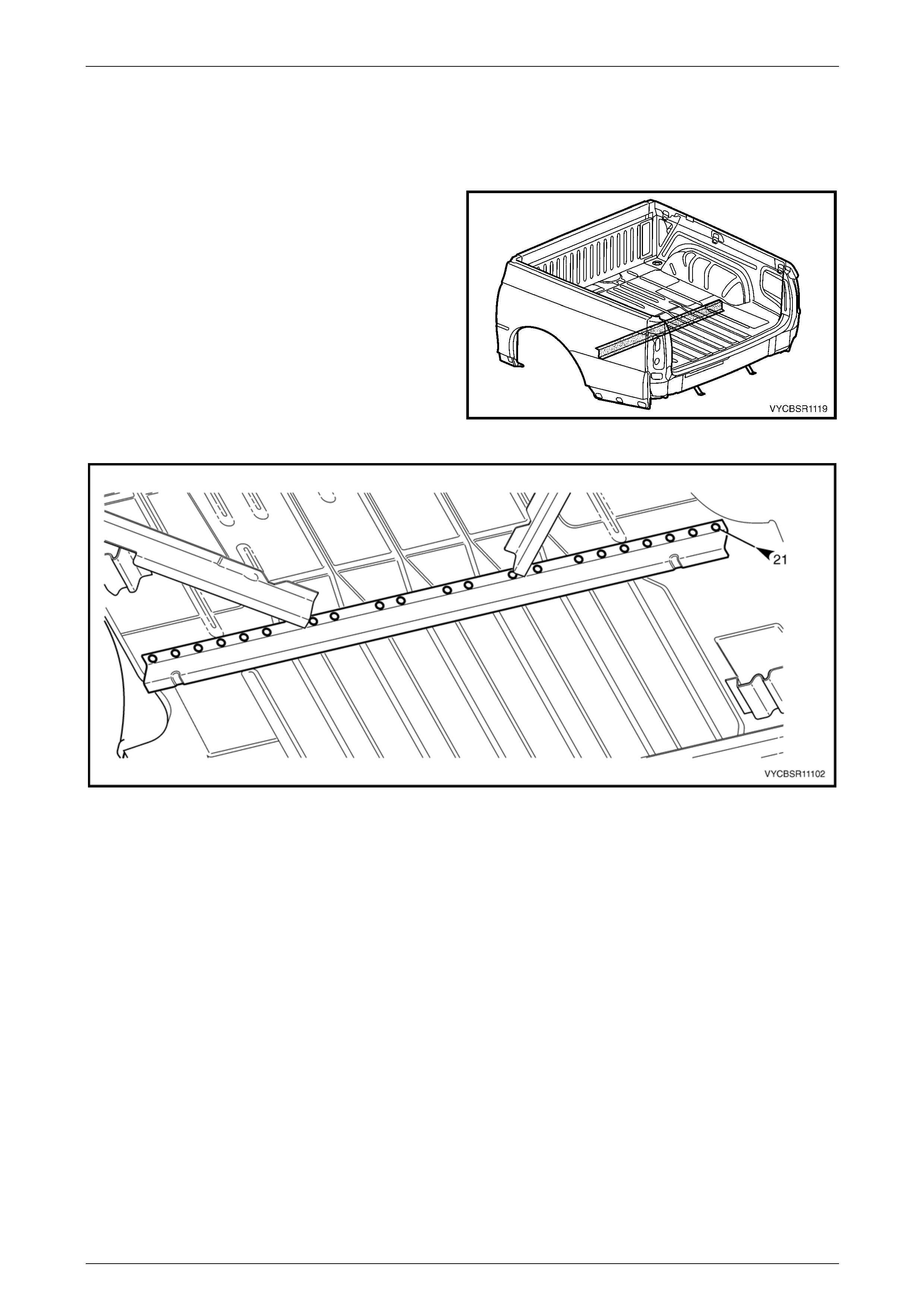
Rear Tray Body Assembly, Crew Cab Page 11–59
Page 11–59
2.19 Load Floor Panel Front Support –
Replace
Remove
1 Remove the rear tray body assembly from the vehicle,
refer to Section 1B Sheetmetal in the MY 2004 VY
Regular Cab and Crew Cab S ervice Information.
2 Remove the adjacent bolt-on panels a nd components
as described in the appropriate Section of the
MY 2004 VY Regular Cab and Crew Cab Service
Information.
3 From underneath the rear tray body assembly, spot
cut the welds attaching either the load floor p anel front
support, refer to Figure 11–105.
Figure 11–104
Figure 11–105
4 Remove the load floor panel front support and repair any damage to adjacent parts as required.
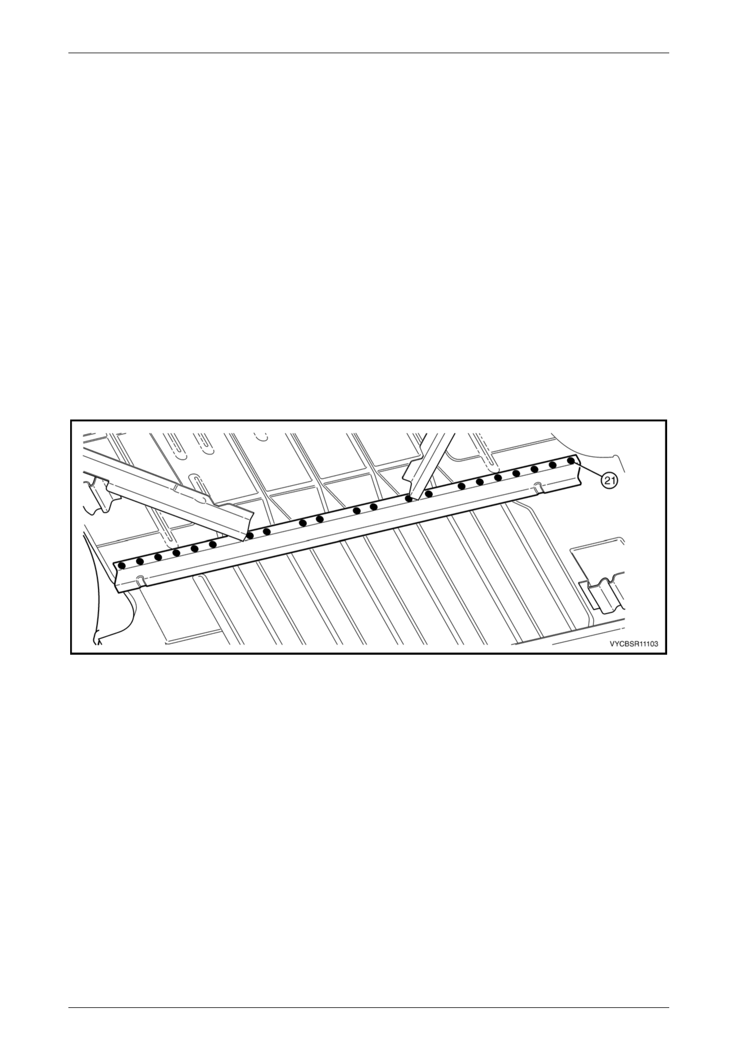
Rear Tray Body Assembly, Crew Cab Page 11–60
Page 11–60
Replace
NOTE
• Spot welding is the preferred method for
attaching of panels and should be used
whenever possible. Where the spot welding
equipment available will not access the
required weld position, a plug weld should be
performed.
• The same number and position of spot welds
(or plug welds) should be used when
replacing the panel, as was used during
manufacture, in order to maintain the original
structural strength of the vehicle.
1 As required, mark the new panel with drilling locations in preparation for plug welding. Drill holes as required.
2 Prepare all mating surfaces and treat with Weld Through Primer (Item 1) as required, refer to Section 3B,
5 Body Sealing, Adhesives & Dea deners.
3 Clamp the load floor panel front support in position, aligning it to the correct dimensions, refer to
3 Underfloor Component Location Dimensions.
4 From underneath the vehicle, spot or plug weld the floor panel front support, refer to Figure 11–106.
Figure 11–106
5 Install any removed panels as required, refer to the appropriate Section in this Supplement.
6 Refinish and paint panels and other components as required, refer to Section 3, 1.3 Paint Refinishing in the MY
2003 VY and V2 Series Service Manual Supplement, Body Structure Repair.
7 Apply Joint Sealer (Item 3) as required, refer to Section 3B, 5 Body Sealing, Adhesives & Deadeners.
8 Apply Cavity Wax (Item 8) as required to the inside of any box sections or areas inaccessible to paint, refer to
Section 3B, 6 Cavity Wax.
9 Reinstall the rear tray body assembly, refer to Section 1B Sheetmetal in the MY 2004 VY Regular Cab and Crew
Cab Service Information.
10 Install the remaining compon ents as described in the appropriate Secti on of the MY 2004 VY Regular Cab and
Crew Cab Service Information.
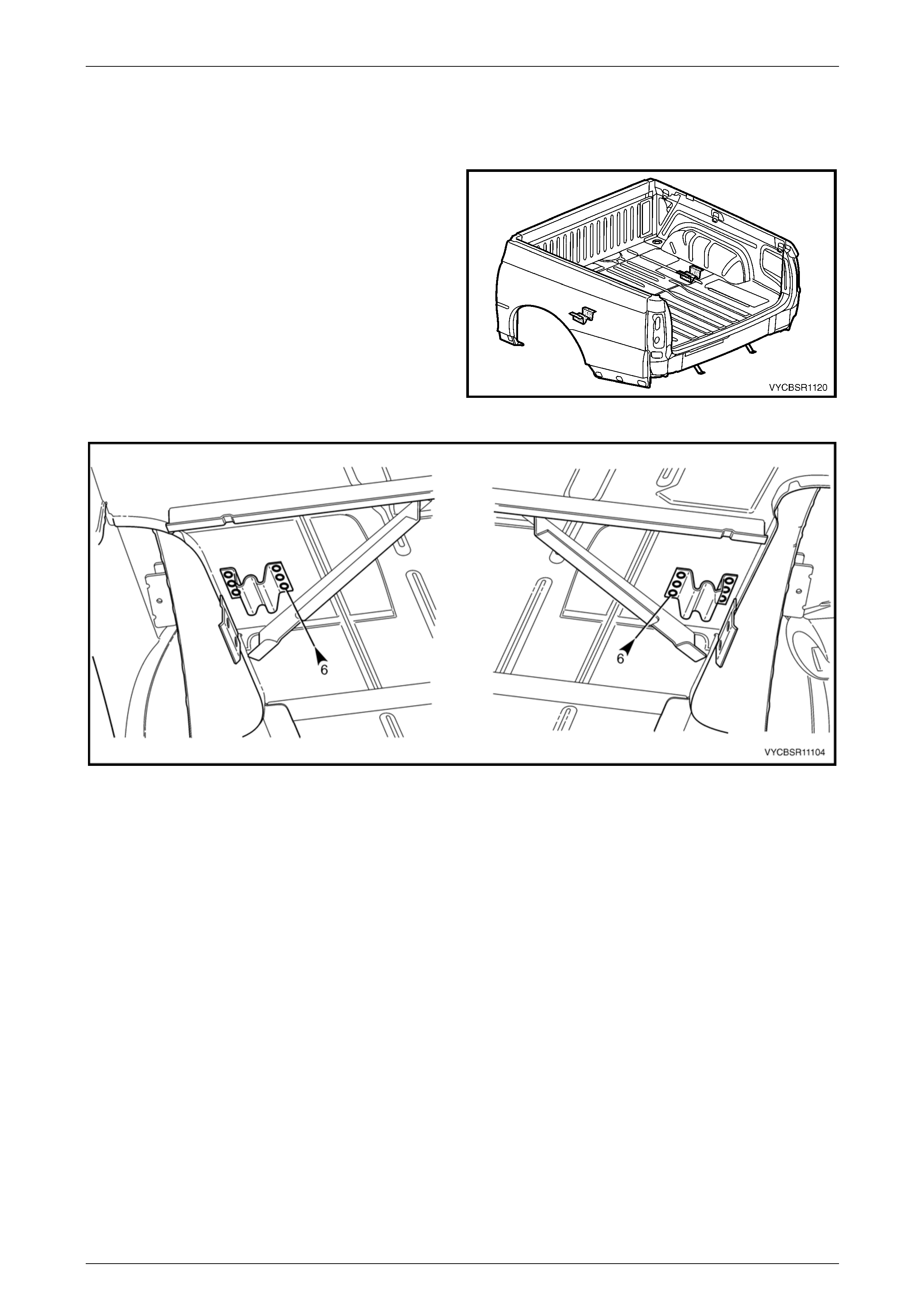
Rear Tray Body Assembly, Crew Cab Page 11–61
Page 11–61
2.20 Load Floor Panel Locator – Replace
Remove
1 Remove the rear tray body assembly from the vehicle,
refer to Section 1B Sheetmetal in the MY 2004 VY
Regular Cab and Crew Cab S ervice Information.
2 Remove the adjacent bolt-on panels a nd components
as described in the appropriate Section of the
MY 2004 VY Regular Cab and Crew Cab Service
Information.
3 From underneath the rear tray body assembly, spot
cut the welds attaching either the left-hand or right-
hand load floor panel locator, refer to Figure 11–108.
Figure 11–107
Figure 11–108
4 Remove the load floor panel locator and repair any damage to adjacent parts as required.
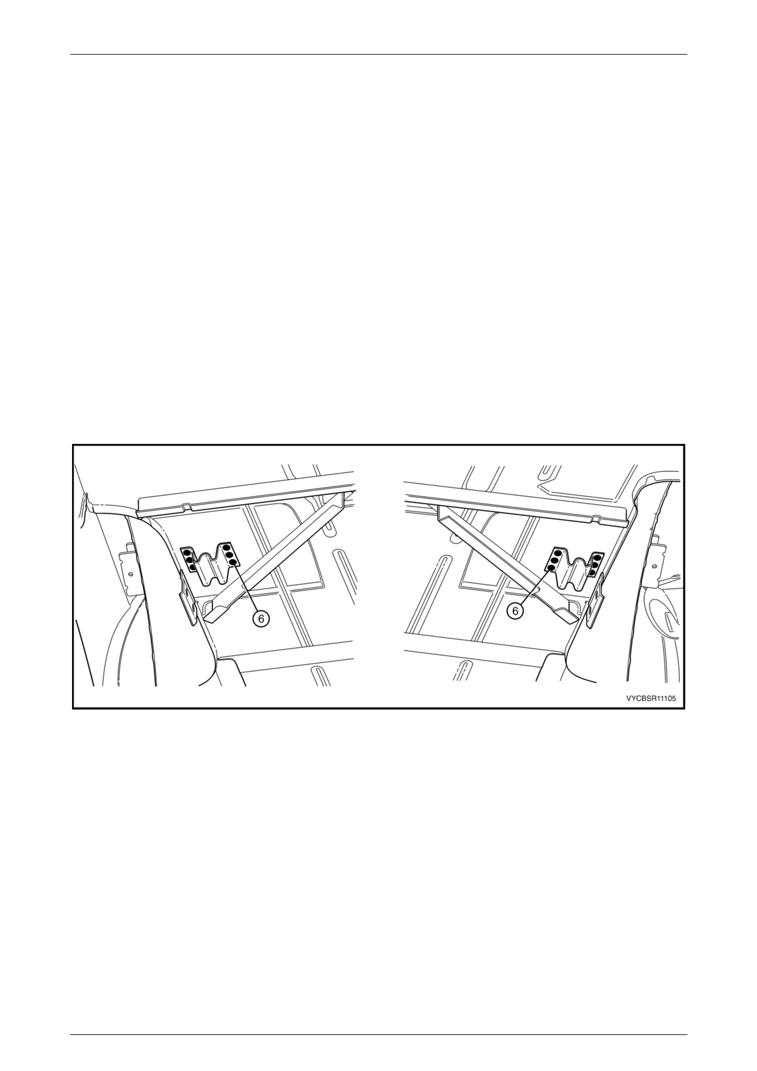
Rear Tray Body Assembly, Crew Cab Page 11–62
Page 11–62
Replace
NOTE
• Spot welding is the preferred method for
attaching of panels and should be used
whenever possible. Where the spot welding
equipment available will not access the
required weld position, a plug weld should be
performed.
• The same number and position of spot welds
(or plug welds) should be used when
replacing the panel, as was used during
manufacture, in order to maintain the original
structural strength of the vehicle.
1 As required, mark the new panel with drilling locations in preparation for plug welding. Drill holes as required.
2 Prepare all mating surfaces and treat with Weld Through Primer (Item 1) as required, refer to Section 3B,
5 Body Sealing, Adhesives & Dea deners.
3 Clamp the load floor panel locator in position, aligning it to the correct dimensions, refer to
3 Underfloor Component Location Dimensions.
4 From underneath the vehicle, spot or plug weld either the left-hand or right-hand load floor pan el locator, refer to
Figure 11–109.
Figure 11–109
5 Install any removed panels as required, refer to the appropriate Section in this Supplement.
6 Refinish and paint panels and other components as required, refer to Section 3, 1.3 Paint Refinishing in the MY
2003 VY and V2 Series Service Manual Supplement, Body Structure Repair.
7 Apply Joint Sealer (Item 3) as required, refer to Section 3B, 5 Body Sealing, Adhesives & Deadeners.
8 Apply Cavity Wax (Item 8) as required to the inside of any box sections or areas inaccessible to paint, refer to
Section 3B, 6 Cavity Wax.
9 Reinstall the rear tray body assembly, refer to Section 1B Sheetmetal in the MY 2004 VY Regular Cab and Crew
Cab Service Information.
10 Install the remaining compon ents as described in the appropriate Secti on of the MY 2004 VY Regular Cab and
Crew Cab Service Information.
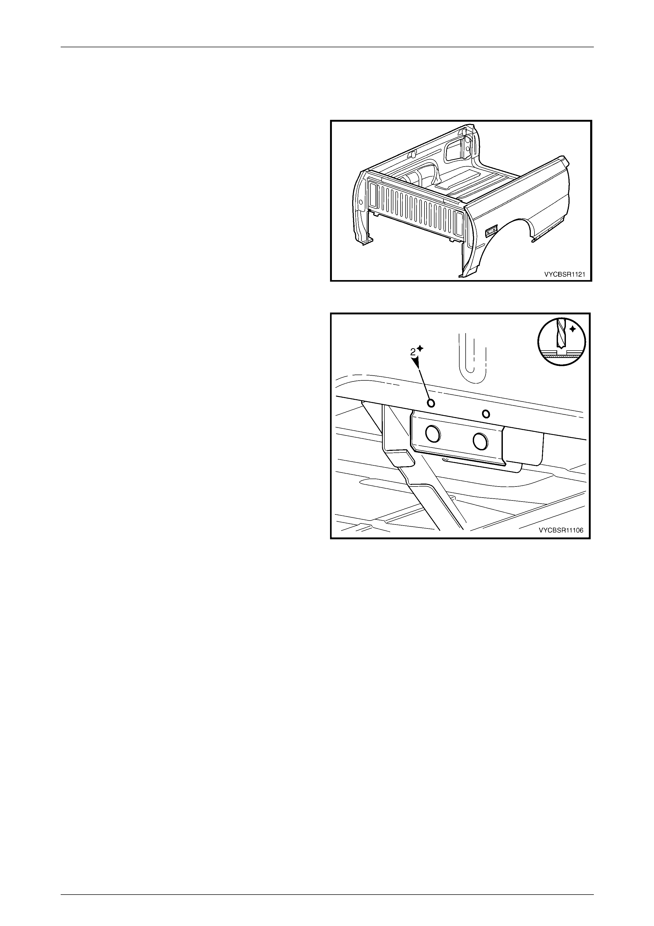
Rear Tray Body Assembly, Crew Cab Page 11–63
Page 11–63
2.21 Load Floor Panel Side Support – Replace
Remove
1 Remove the adjacent bolt-on panels a nd components
as described in the appropriate Section of the
MY 2004 VY Regular Cab and Crew Cab Service
Information.
Figure 11–110
2 Spot cut the welds attaching either the left-hand or
right-hand load floor panel si de support, left-hand
shown.
3 Remove the side support and repair any damage to
adjacent parts as required.
Figure 11–111
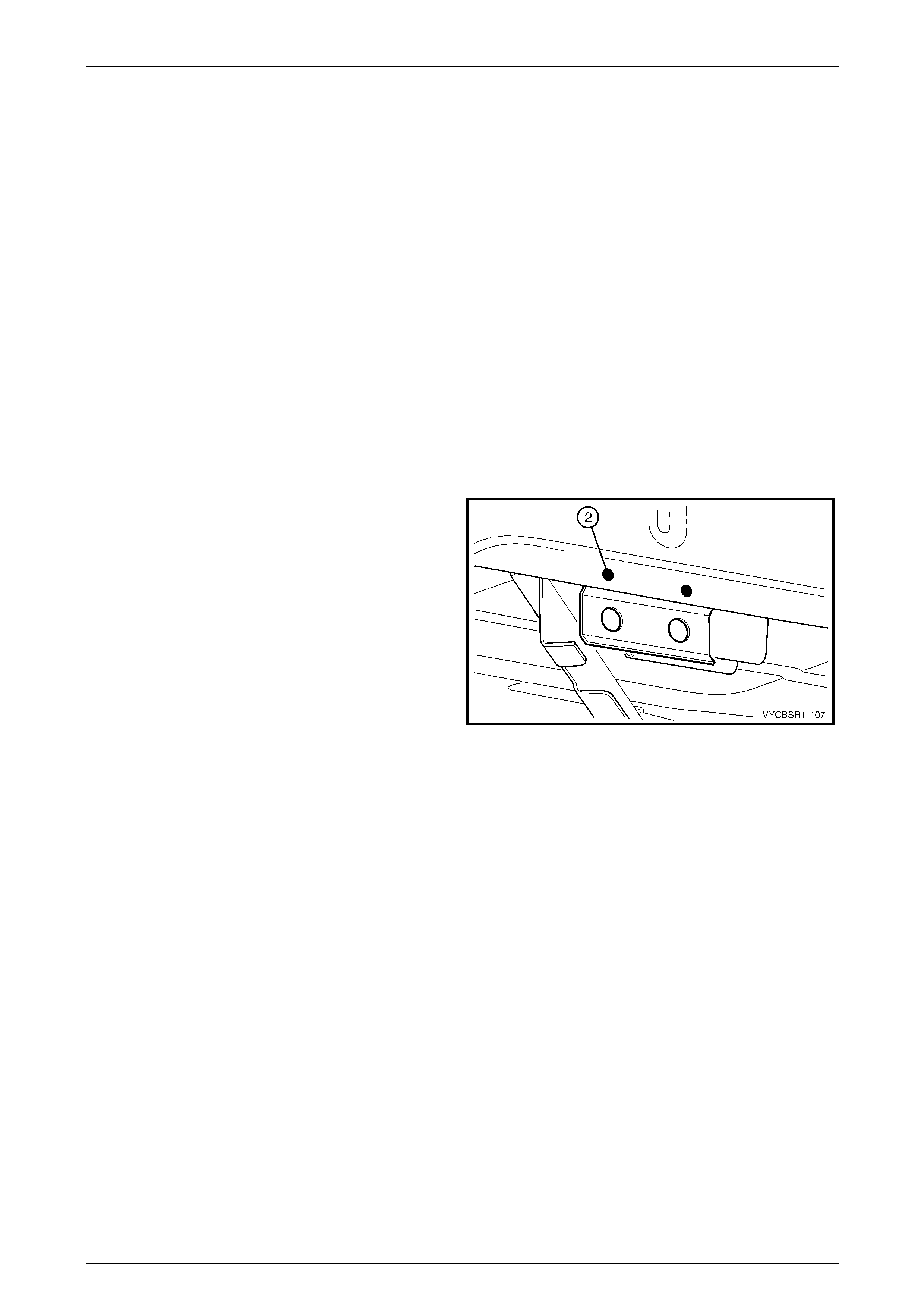
Rear Tray Body Assembly, Crew Cab Page 11–64
Page 11–64
Replace
NOTE
• Spot welding is the preferred method for
attaching of panels and should be used
whenever possible. Where the spot welding
equipment available will not access the
required weld position, a plug weld should be
performed.
• The same number and position of spot welds
(or plug welds) should be used when
replacing the panel, as was used during
manufacture, in order to maintain the original
structural strength of the vehicle.
1 As required, mark the new panel with drilling locations in preparation for plug welding. Drill holes as required.
2 Prepare all mating surfaces and treat with Weld Through Primer (Item 1) as required, refer to Section 3B,
5 Body Sealing, Adhesives & Dea deners.
3 Clamp the load floor panel side support in position, aligning it to the correct dimensions, refer to
3 Underfloor Component Location Dimensions.
4 Spot or plug weld the load floor panel side support to
the rear tray body assembly.
5 Install any removed panels as required, refer to the
appropriate Section in this Supplement.
6 Refinish and paint panels and other components as
required, refer to Section 3, 1.3 Paint Refinishing in
the MY 2003 VY and V2 Series Service Manual
Supplement, Body Structure Repair.
7 Apply Joint Sealer (Item 3) as required, refer to
Section 3B, 5 Body Sealing, Adhesives & Deadeners.
8 Apply Cavity Wax (Item 8) as required to the inside of
any box sections or areas inaccessible to paint, refer
to Section 3B, 6 Cavity Wax. Figure 11–112
9 Install the remaining components as described in the appropriate Section of the MY 2004 VY Regular Cab and
Crew Cab Service Information.
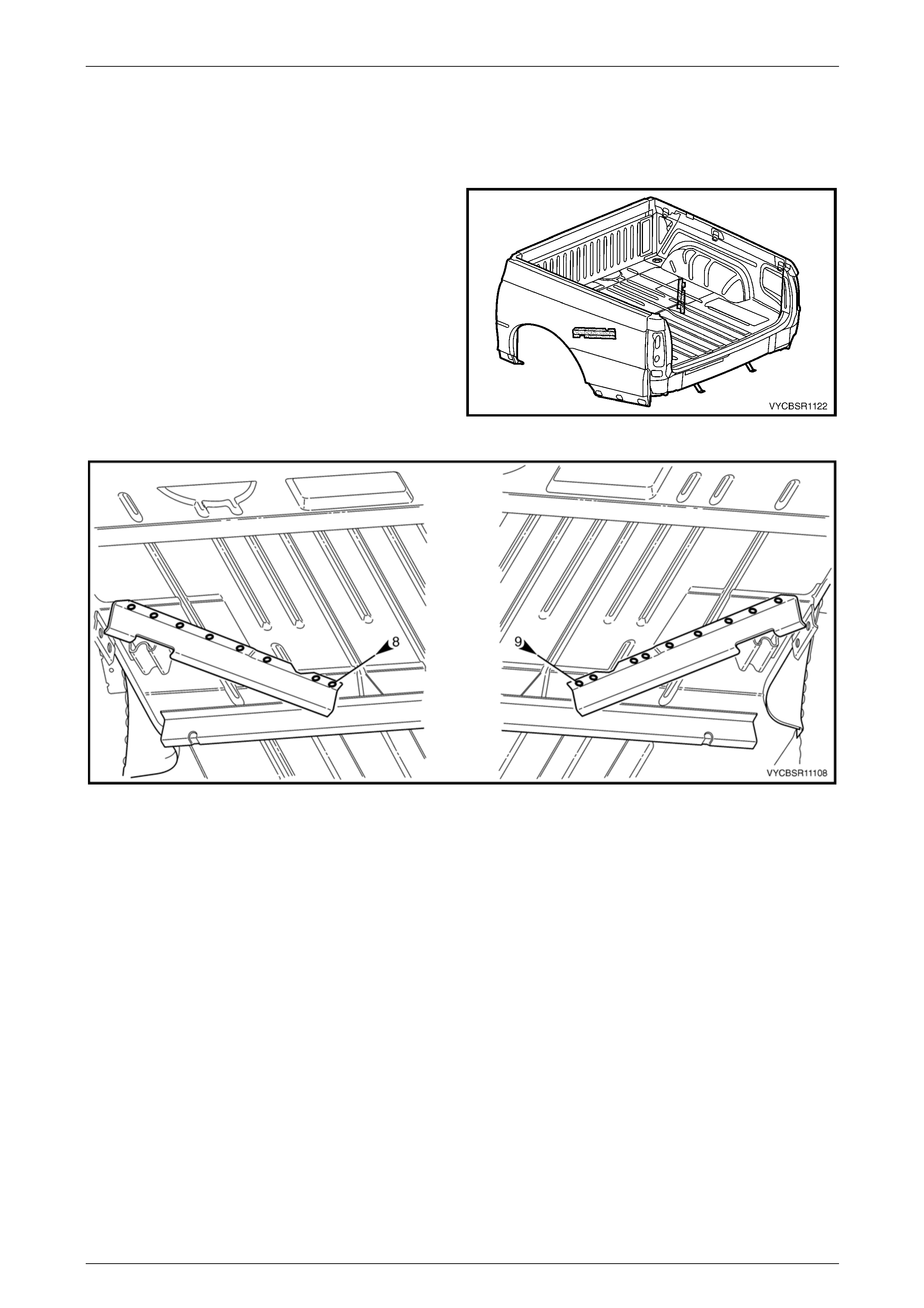
Rear Tray Body Assembly, Crew Cab Page 11–65
Page 11–65
2.22 Load Floor Panel Support – Replace
Remove
1 Remove the rear tray body assembly from the vehicle,
refer to Section 1B Sheetmetal in the MY 2004 VY
Regular Cab and Crew Cab S ervice Information.
2 Remove the adjacent bolt-on panels a nd components
as described in the appropriate Section of the
MY 2004 VY Regular Cab and Crew Cab Service
Information.
3 From underneath the rear tray body assembly, spot
cut the welds attaching either the left-hand or right-
hand load floor panel sup port, refer to F igure 11–114.
Figure 11–113
Figure 11–114
4 Remove the load floor panel support and repair any damage to adjacent parts as requir ed.

Rear Tray Body Assembly, Crew Cab Page 11–66
Page 11–66
Replace
NOTE
• Spot welding is the preferred method for
attaching of panels and should be used
whenever possible. Where the spot welding
equipment available will not access the
required weld position, a plug weld should be
performed.
• The same number and position of spot welds
(or plug welds) should be used when
replacing the panel, as was used during
manufacture, in order to maintain the original
structural strength of the vehicle.
1 As required, mark the new panel with drilling locations in preparation for plug welding. Drill holes as required.
2 Prepare all mating surfaces and treat with Weld Through Primer (Item 1) as required, refer to Section 3B,
5 Body Sealing, Adhesives & Dea deners.
3 Clamp the load floor panel support in position, aligning it to the correct dimensions, refer to
3 Underfloor Component Location Dimensions.
4 From underneath the vehicle, spot or plug weld either the left-hand or right-hand load floor pan el support, refer to
Figure 11–115.
Figure 11–115
5 Install any removed panels as required, refer to the appropriate Section in this Supplement.
6 Refinish and paint panels and other components as required, refer to Section 3, 1.3 Paint Refinishing in the MY
2003 VY and V2 Series Service Manual Supplement, Body Structure Repair.
7 Apply Joint Sealer (Item 3) as required, refer to Section 3B, 5 Body Sealing, Adhesives & Deadeners.
8 Apply Cavity Wax (Item 8) as required to the inside of any box sections or areas inaccessible to paint, refer to
Section 3B, 6 Cavity Wax.
9 Reinstall the rear tray body assembly, refer to Section 1B Sheetmetal in the MY 2004 VY Regular Cab and Crew
Cab Service Information.
10 Install the remaining compon ents as described in the appropriate Secti on of the MY 2004 VY Regular Cab and
Crew Cab Service Information.
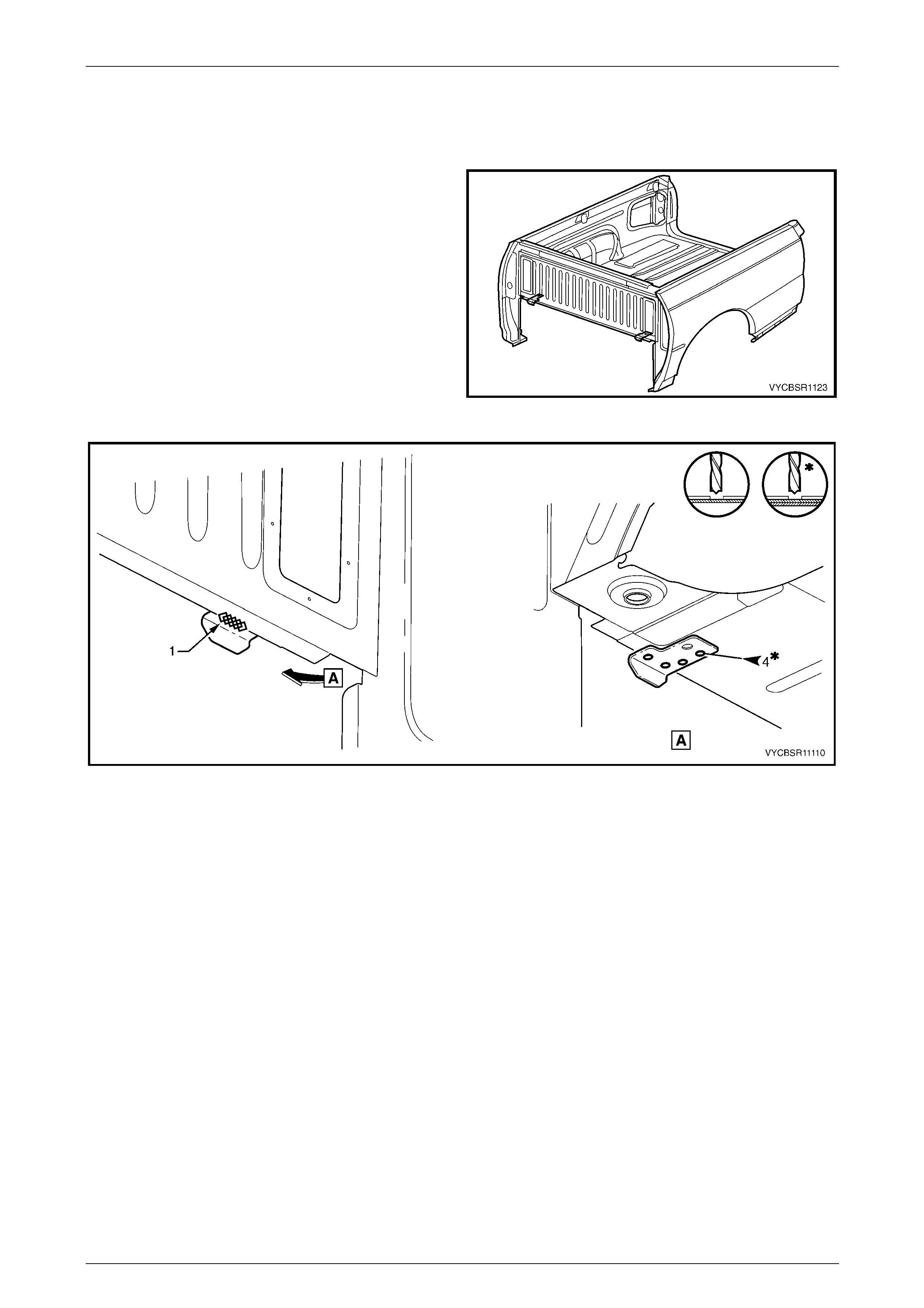
Rear Tray Body Assembly, Crew Cab Page 11–67
Page 11–67
2.23 Front End Panel Locator – Replace
Remove
1 Remove the rear tray body assembly from the vehicle,
refer to Section 1B Sheetmetal in the MY 2004 VY
Regular Cab and Crew Cab S ervice Information.
2 Remove the adjacent bolt-on panels a nd components
as described in the appropriate Section of the
MY 2004 VY Regular Cab and Crew Cab Service
Information.
3 Grind off the MIG weld (1) attaching the locator the
rear tray body assembly front flange, refer to
Figure 11–117.
4 From underneath the rear tray body assembly, spot
cut the welds attaching either the left-hand or right-
hand front end panel locator, l eft-hand sh own. Figure 11–116
Figure 11–117
5 Remove the locator and repair any damage to adjacent parts as required.

Rear Tray Body Assembly, Crew Cab Page 11–68
Page 11–68
Replace
NOTE
• Spot welding is the preferred method for
attaching of panels and should be used
whenever possible. Where the spot welding
equipment available will not access the
required weld position, a plug weld should be
performed.
• The same number and position of spot welds
(or plug welds) should be used when
replacing the panel, as was used during
manufacture, in order to maintain the original
structural strength of the vehicle.
1 As required, mark the new panel with drilling locations in preparation for plug welding. Drill holes as required.
2 Prepare all mating surfaces and treat with Weld Through Primer (Item 1) as required, refer to Section 3B,
5 Body Sealing, Adhesives & Dea deners.
3 Clamp the front end panel locator in position, aligning it to the hole in the load compartme nt floor.
4 Spot or plug weld the locator to the rear tray body assembl y, refer to Figure 11–118.
5 MIG weld (1) the locator to the rear tray body assembly front flange.
Figure 11–118
6 Install any removed panels as required, refer to the appropriate Section in this Supplement.
7 Refinish and paint panels and other components as required, refer to Section 3, 1.3 Paint Refinishing in the MY
2003 VY and V2 Series Service Manual Supplement, Body Structure Repair.
8 Apply Joint Sealer (Item 3) as required, refer to Section 3B, 5 Body Sealing, Adhesives & Deadeners.
9 Apply Cavity Wax (Item 8) as required to the inside of any box sections or areas inaccessible to paint, refer to
Section 3B, 6 Cavity Wax.
10 Reinstall the rear tray body assembly, refer to Section 1B Sheetmetal in the MY 2004 VY Regular C ab and Crew
Cab Service Information.
11 Install the remaining compon ents as described in the appropriate Secti on of the MY 2004 VY Regular Cab and
Crew Cab Service Information.
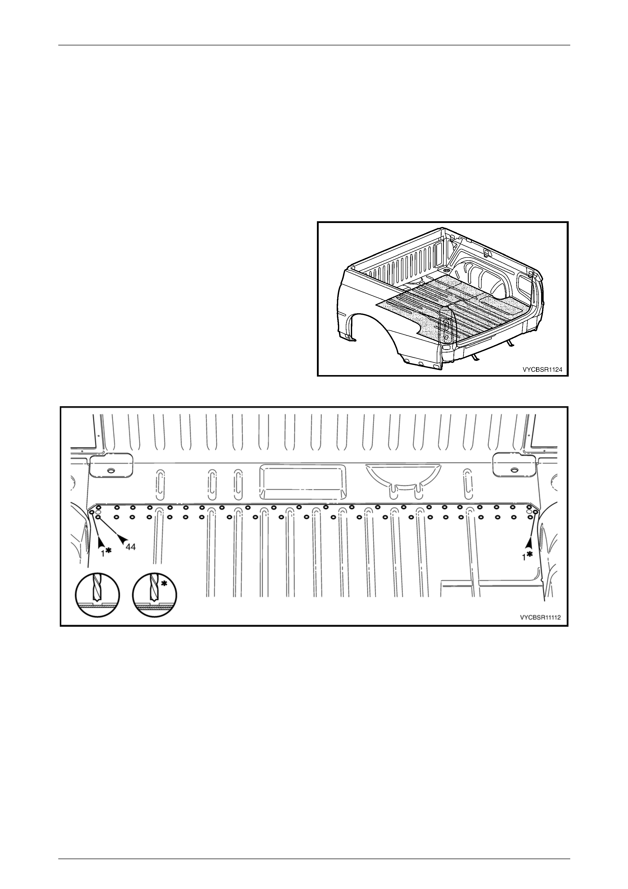
Rear Tray Body Assembly, Crew Cab Page 11–69
Page 11–69
2.24 Load Floor Panel – Replace
NOTE
The load floor panel is serviced separately. The
following procedure describes removing the load
floor panel as an assembly with the supports and
locators, and then provides references to the
relevant procedures for the installation of these
components.
Remove
1 Remove the rear tray body assembly from the vehicle,
refer to Section 1B Sheetmetal in the MY 2004 VY
Regular Cab and Crew Cab S ervice Information.
2 Remove the adjacent bolt-on panels a nd components
as described in the appropriate Section of the
MY 2004 VY Regular Cab and Crew Cab Service
Information.
3 Remove the sealer and floor dead ener panels from the
relevant areas using a scraper and heat gun.
4 Remove the adjoining panels as required, refer to the
appropriate Section of this Supplement.
5 Spot cut the welds attaching the load floor panel to the
load floor front extension, refer to Figure 11–120. Figure 11–119
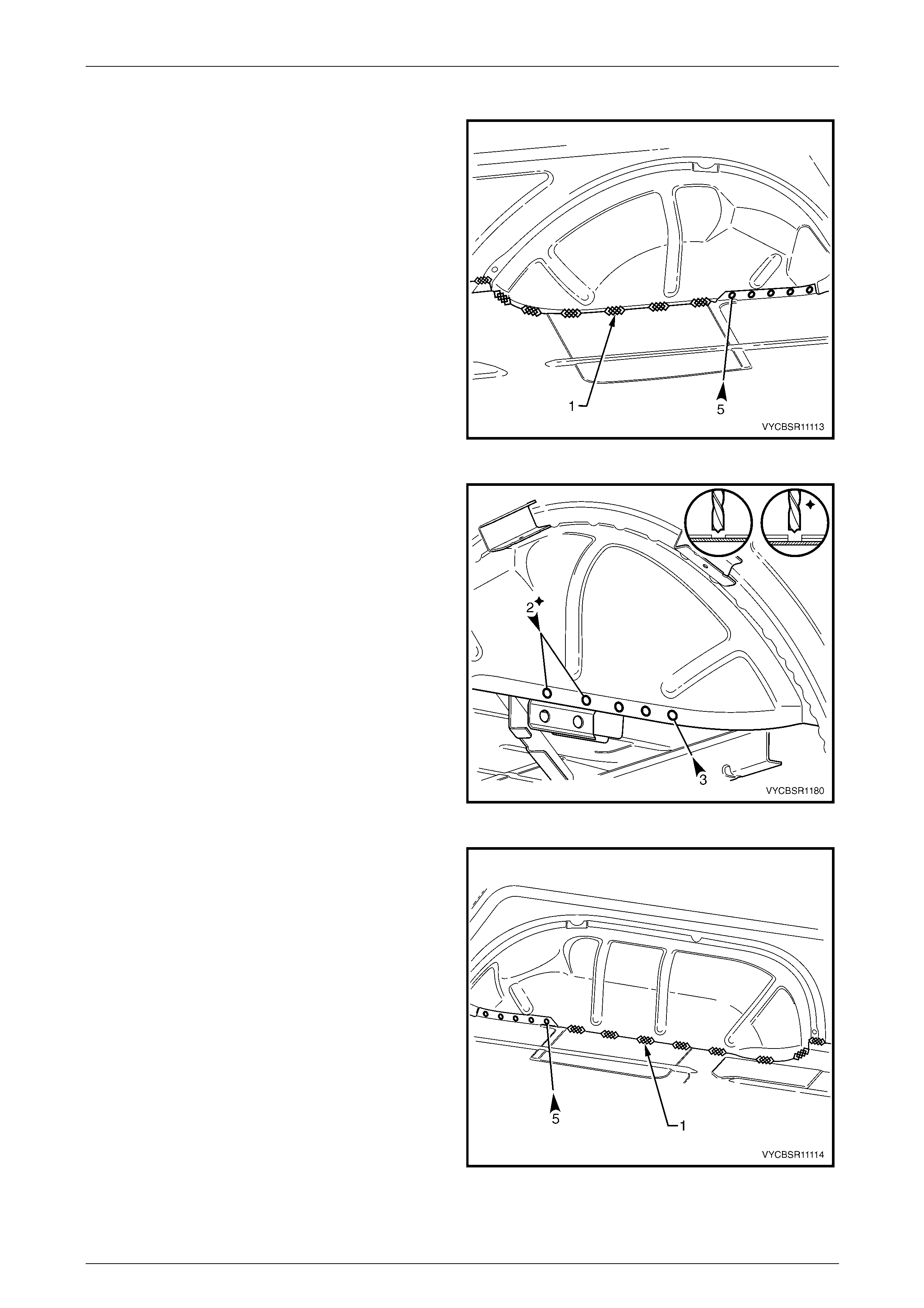
Rear Tray Body Assembly, Crew Cab Page 11–70
Page 11–70
Figure 11–120
6 For the left-hand side, spot cut the welds attaching the
load floor panel to the wheelhouse inn er pan el.
7 Grind off the MIG welds (1), attaching the load floor
panel to the rear wheelhouse inner panel and inner
side panel.
Figure 11–121
8 Spot cut the welds attaching the rear wheelhouse
inner panel to the load floor panel assembly from
underneath the rear tray body assembly.
Figure 11–122
9 For the right-hand side, spot cut the welds attaching
the load floor panel to the wheelhouse inner panel.
10 Grind off the MIG welds (1), attaching the load floor
panel to the rear wheelhouse inner panel and inner
side panel.
Figure 11–123
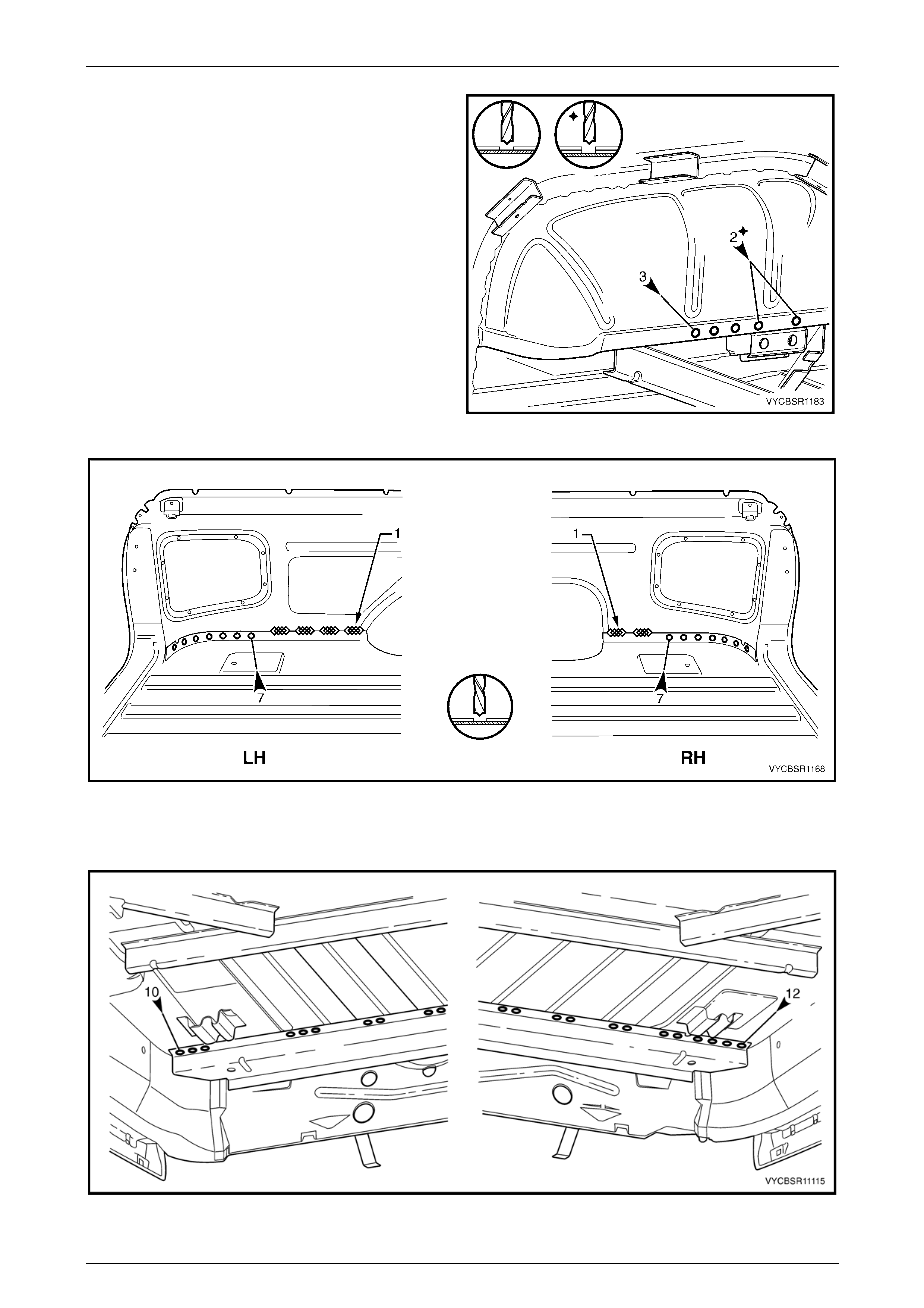
Rear Tray Body Assembly, Crew Cab Page 11–71
Page 11–71
11 Spot cut the welds attaching the rear wheelhouse
inner panel to the load floor panel assembly from
underneath the rear tray body assembly.
12 Spot cut the welds attaching the load floor panel to the
inner side panel on each side of the vehicle, refer to
Figure 11–125.
13 Grind off the MIG welds (1), attaching the load floor
panel to the inner side panel on each side of the
vehicle.
Figure 11–124
Figure 11–125
14 From underneath the vehicle, spot cut the welds attaching the load floor panel rear su pport to the load floor panel,
refer to Figure 11–126.
Figure 11–126

Rear Tray Body Assembly, Crew Cab Page 11–72
Page 11–72
15 Spot cut the welds attaching the rear end panel to the load floor panel, refer to Figure 11–127.
16 Grind off the MIG welds (1), attaching the load floor panel to the inner side panel on each side of the vehicle.
Figure 11–127
17 Remove the load floor panel and repair any damage to adj acent parts as required.
18 Check and rectify the alignme nt of the body as required, refer to Section 3B, 3 Body Dimensions.
Replace
NOTE
• Spot welding is the preferred method for
attaching of panels and should be used
whenever possible. Where the spot welding
equipment available will not access the
required weld position, a plug weld should be
performed.
• The same number and position of spot welds
(or plug welds) should be used when
replacing the panel, as was used during
manufacture, in order to maintain the original
structural strength of the vehicle.
1 As required, mark the new panel with drilling locations in preparation for plug welding. Drill holes as required.
2 Prepare all mating surfaces and treat with Weld Through Primer (Item 1) as required, refer to Section 3B,
5 Body Sealing, Adhesives & Dea deners.
3 Install the load floor panel and clamp in position.
4 Spot or plug weld the load floor panel to the load floor front extension, refer to Figure 11–128.
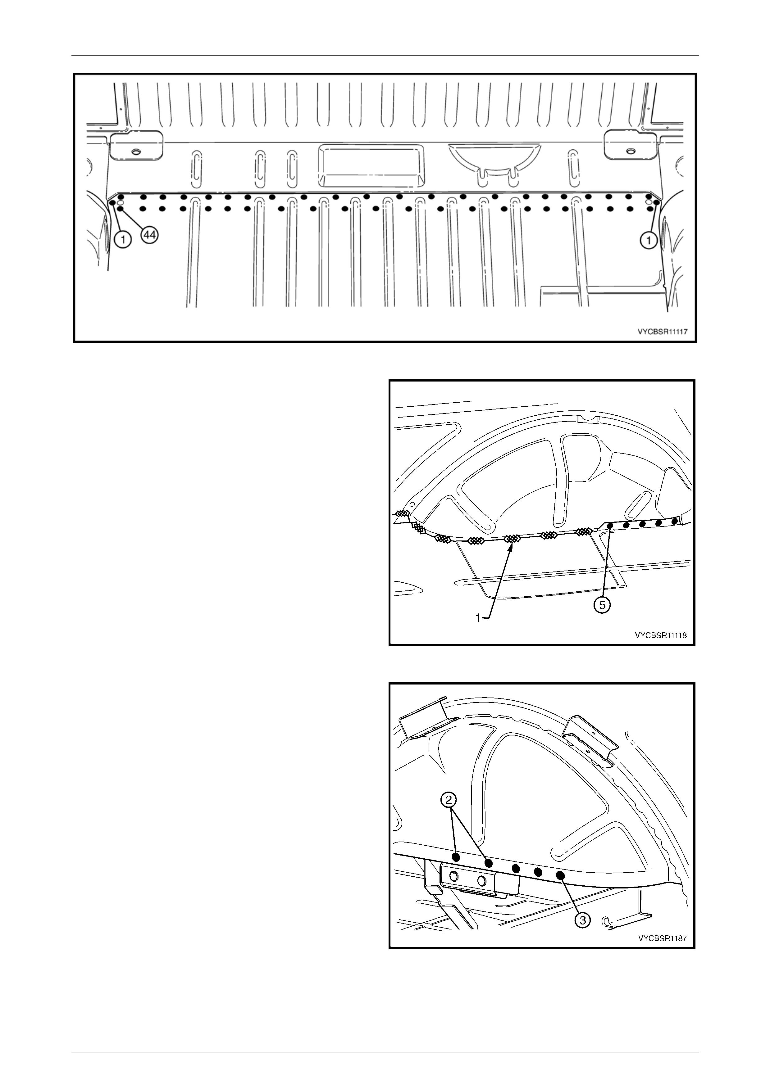
Rear Tray Body Assembly, Crew Cab Page 11–73
Page 11–73
Figure 11–128
5 For the left-hand side, spot or plug weld the load floor
panel to the wheelhouse inner panel.
6 MIG weld (1) the load floor panel to the rear
wheelhouse inner panel and inner side panel.
Figure 11–129
7 Spot or plug weld the rear wheelhouse inner panel to
the load floor panel assembly from under neath the
rear tray body assembly.
Figure 11–130
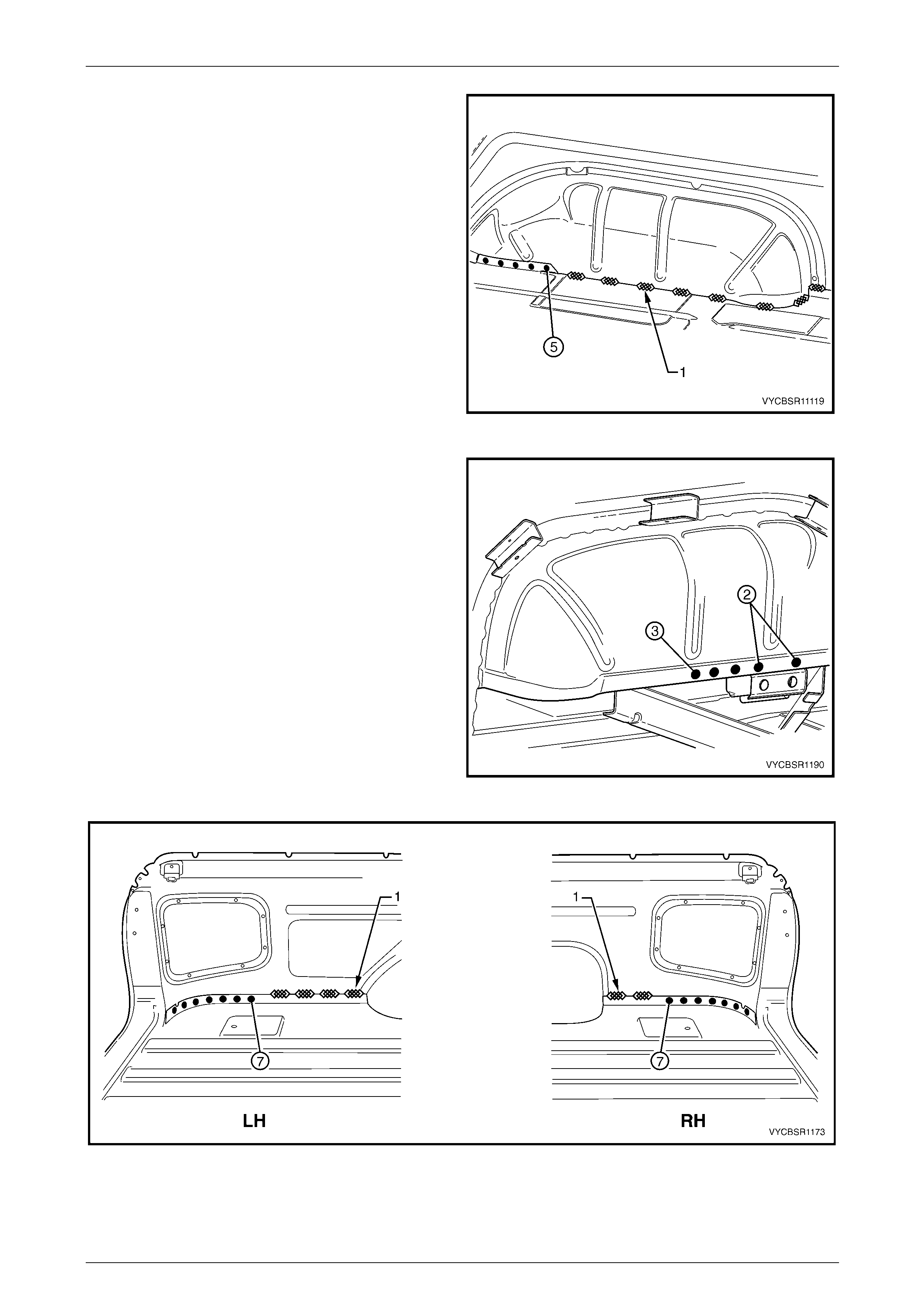
Rear Tray Body Assembly, Crew Cab Page 11–74
Page 11–74
8 For the right-hand side, spot or plug weld the load floor
panel to the wheelhouse inner panel.
9 MIG weld (1) the load floor panel to the rear
wheelhouse inner panel and inner side panel.
Figure 11–131
10 Spot or plug weld the rear wheelhouse inner panel to
the load floor panel assembly from under neath the
rear tray body assembly.
11 Spot or plug weld the load floor panel to the inner side
panel on each side of the vehicle, refer to
Figure 11–133.
12 MIG weld (1) the load floor panel to the inner side
panel on each side of the vehicle.
Figure 11–132
Figure 11–133
13 From underneath the vehicle, spot or plug weld the load floor panel rear support to the load floor panel, refer to
Figure 11–134.
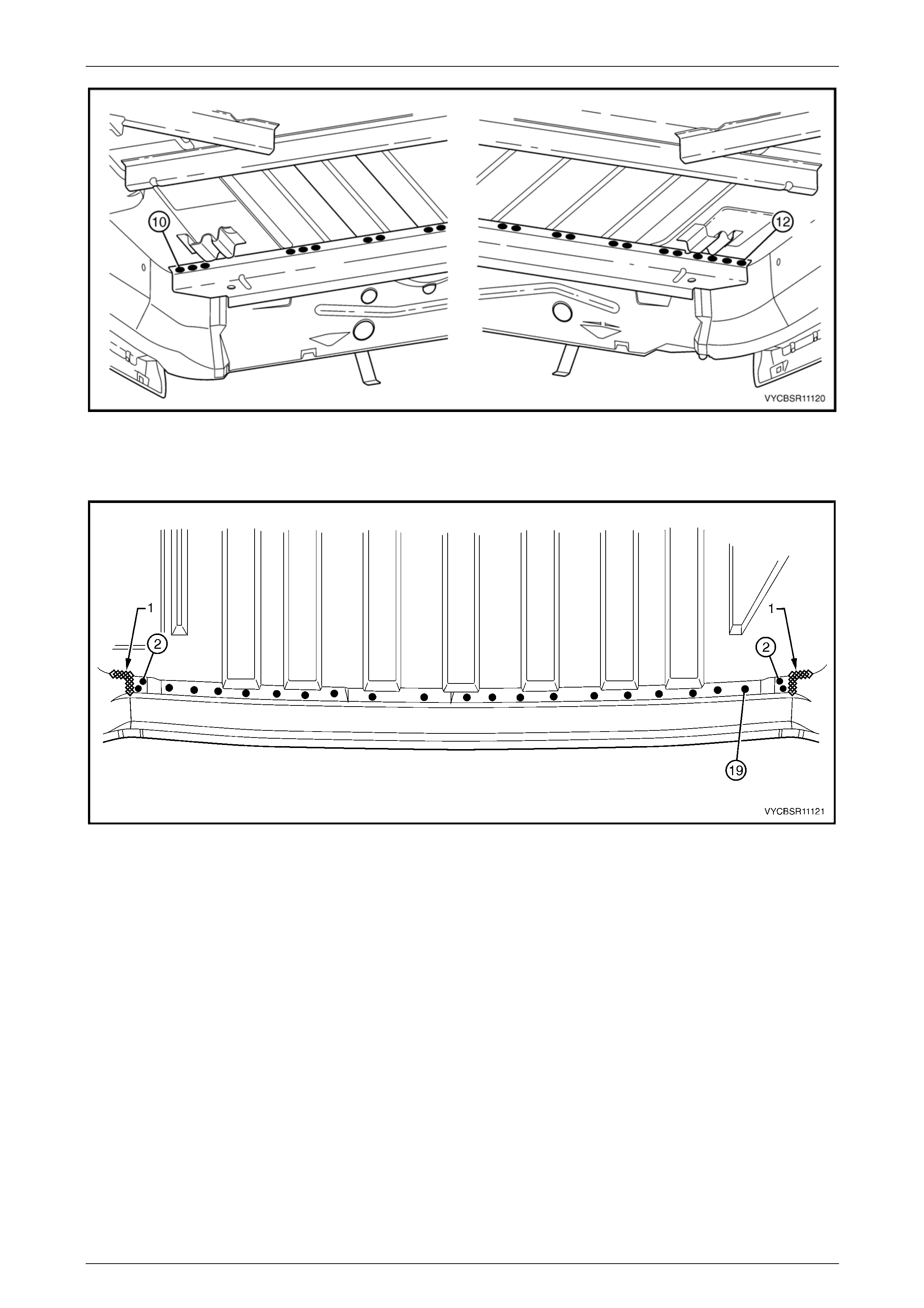
Rear Tray Body Assembly, Crew Cab Page 11–75
Page 11–75
Figure 11–134
14 Spot or plug weld the rear end panel to the load floor panel, refer to Figure 11–135.
15 MIG weld (1) the load floor panel to the inner side panel on each side of the vehicle.
Figure 11–135
16 Install the following components:
a Load floor panel locator guide , refer to 2.18 Load Floor Panel Locator Guide – Replace.
b Load floor panel front support, refer to 2.19 Load Floor Panel Front Support – Replace.
c Load floor panel locator, refer to 2.20 Load Floor Panel L ocator – Replace.
d Load floor panel side support s , refer to 2.21 Load Flo or Panel Side Support – Replace.
e Load floor panel supports, refer to 2.22 Load Floor Panel Support – Replace.
17 Install any removed panels as required, refer to the appropriate Section in this Supplement.
18 Refinish and paint panels and other components as required, refer to Section 3, 1.3 Paint Refinishing in the MY
2003 VY and V2 Series Service Manual Supplement, Body Structure Repair.
19 Apply Joint Sealer (Item 3) as required, refer to Section 3B, 5 Body Sealing, Adhesives & Deadeners.
20 Apply Cavity Wax (Item 8) as required to the inside of any box sections or areas inaccessible to paint, refer to
Section 3B, 6 Cavity Wax.
21 Reinstall the rear tray body assembly, refer to Section 1B Sheetmetal in the MY 2004 VY Regular C ab and Crew
Cab Service Information.
22 Install the remaining compon ents as described in the appropriate Secti on of the MY 2004 VY Regular Cab and
Crew Cab Service Information.
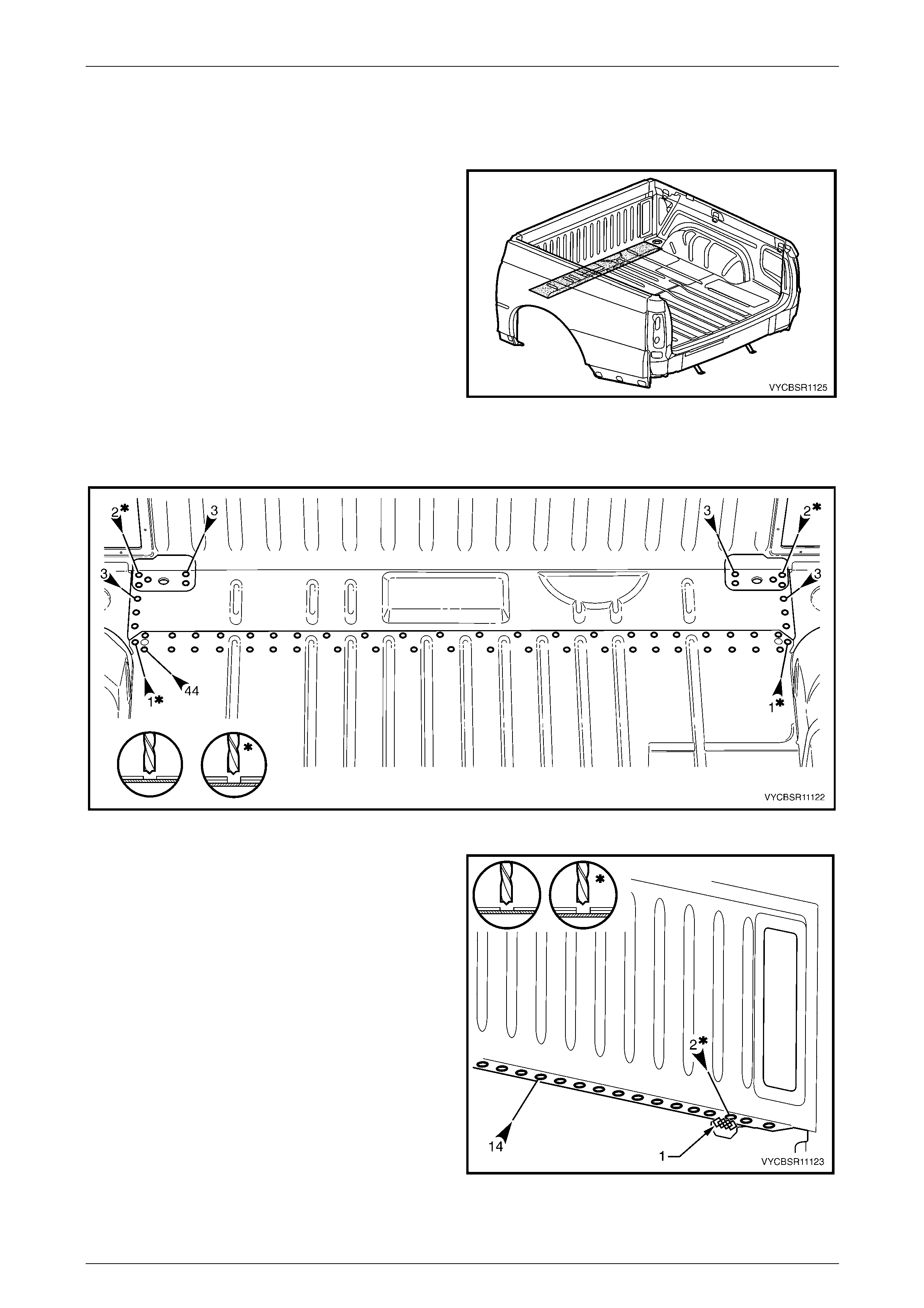
Rear Tray Body Assembly, Crew Cab Page 11–76
Page 11–76
2.25 Load Floor Front Extension – Replace
Remove
1 Remove the rear tray body assembly from the vehicle,
refer to Section 1B Sheetmetal in the MY 2004 VY
Regular Cab and Crew Cab S ervice Information.
2 Remove the adjacent bolt-on panels a nd components
as described in the appropriate Section of the
MY 2004 VY Regular Cab and Crew Cab Service
Information.
3 Remove the sealer and floor dead ener panels from the
relevant areas using a scraper and heat gun.
4 Remove the adjoining panels as required, refer to the
appropriate Section of this Supplement.
Figure 11–136
5 Spot cut the welds attaching the load floor pane l and load floor panel front extension to the load floor front
extension, refer to Figure 11– 137.
Figure 11–137
6 From each side of the rear tray body assembly, spot
cut the welds attaching the front end panel to the load
floor front, left-hand shown.
7 Grind off the MIG weld (1), attaching the front end
panel locator to the load floor front extension.
8 Remove the load floor front extension and repair any
damage to adjacent parts as required.
9 Check and rectify the alignme nt of the bod y as
required, refer to Section 3B, 3 Body Dimensions.
Figure 11–138
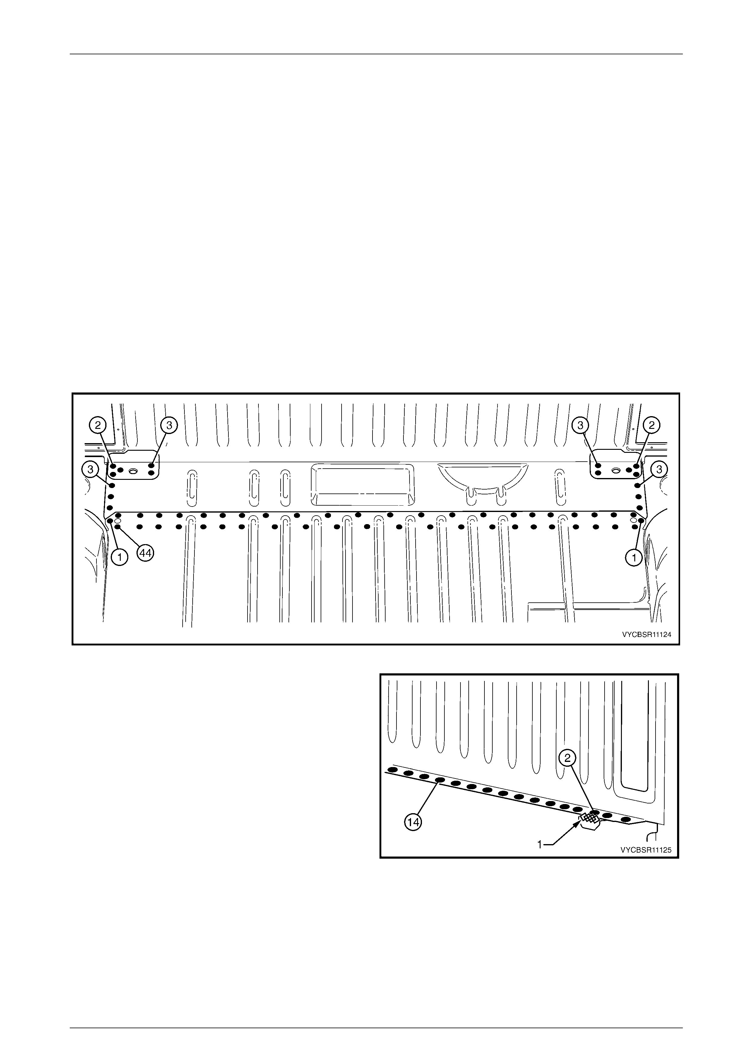
Rear Tray Body Assembly, Crew Cab Page 11–77
Page 11–77
Replace
NOTE
• Spot welding is the preferred method for
attaching of panels and should be used
whenever possible. Where the spot welding
equipment available will not access the
required weld position, a plug weld should be
performed.
• The same number and position of spot welds
(or plug welds) should be used when
replacing the panel, as was used during
manufacture, in order to maintain the original
structural strength of the vehicle.
1 As required, mark the new panel with drilling locations in preparation for plug welding. Drill holes as required.
2 Prepare all mating surfaces and treat with Weld Through Primer (Item 1) as required, refer to Section 3B,
5 Body Sealing, Adhesives & Dea deners.
3 Install the load floor front extension and clamp in position.
4 Spot or plug weld the load floor panel and load floor panel front extension to the load floor front extension, refer to
Figure 11–139.
Figure 11–139
5 From each side of the rear tray body assembly, spot or
plug weld the front end panel to the load floor front,
left-hand shown.
6 MIG weld (1) the front end panel locator to the load
floor front extension.
7 As required, install the front end pane l locators, refer
to 2.23 Front End Panel Locator – Rep lace.
8 Install any removed panels as required, refer to the
appropriate Section in this Supplement.
9 Refinish and paint panels and other components as
required, refer to Section 3, 1.3 Paint Refinishing in
the MY 2003 VY and V2 Series Service Manual
Supplement, Body Structure Repair.
10 Apply Joint Sealer (Item 3) as required, refer to
Section 3B, 5 Body Sealing, Adhesives & Deadeners.
Figure 11–140
11 Apply Cavity Wax (Item 8) as required to the inside of any box sections or areas inaccessible to paint, refer to
Section 3B, 6 Cavity Wax.
12 Reinstall the rear tray body assembly, refer to Section 1B Sheetmetal in the MY 2004 VY Regular C ab and Crew
Cab Service Information.
13 Install the remaining compon ents as described in the appropriate Secti on of the MY 2004 VY Regular Cab and
Crew Cab Service Information.
Rear Tray Body Assembly, Crew Cab Page 11–78
Page 11–78
3 Underfloor Component Location
Dimensi ons
Figure 11–141
NOTE
• X: 0 = front edge of the load floor front
extension.
• Y: 0 = centreline of load floor assembly.
Measure from Ref Y points; the front edge of
the load floor front extensio n and the c entre o f
the rear drain holes. Note the offset of the
drain holes.