
1 General Information Page 1-1
Page 1-1
Section 1
General Information
ATTENTION
Before performing any service operation or other procedure described in this Section, refer to Section 2
Precautions in this Supplement and Section 00 Warnings, Cautions and Notes in the MY2005 VZ Service
Information for correct workshop practices with regard to safety and/or property damage.
The structure of the body shell has been
developed using complex design and
development techniques. In addition to
meeting all required standards, the vehicle
body is also a critical part of the overall safety
systems. It is therefore imperative the repair
procedures described here are adhered to
during all vehicle body repairs.
1 Introduction.............................................................................................................................................2
2 Body Components .................................................................................................................................3
Sedan...................................................................................................................................................................... 3
Wagon..................................................................................................................................................................... 3
Utility....................................................................................................................................................................... 4
Coupe...................................................................................................................................................................... 4
Regular Cab............................................................................................................................................................ 5
Crew Cab ................................................................................................................................................................ 5
AWD Wagon ........................................................................................................................................................... 6
3 Repair Procedures .................................................................................................................................7
3.1 Frame Straightening.............................................................................................................................................. 7
3.2 Rough Cutting........................................................................................................................................................ 8
3.3 Cutting MIG Welds................................................................................................................................................. 9
3.4 Spot Weld Cutting................................................................................................................................................ 10
3.5 Lap Jointing.......................................................................................................................................................... 11
3.6 Repairing the Body Alignment............................................................................................................................ 12
4 Weld Repair Methods...........................................................................................................................13
4.1 General Information............................................................................................................................................. 13
4.2 Spot Welding........................................................................................................................................................ 14
Spot Welder.......................................................................................................................................................... 15
Panel Condition.................................................................................................................................................... 16
Number of Welds ................................................................................................................................................. 16
Weld Testing......................................................................................................................................................... 16
4.3 Plug Welding........................................................................................................................................................ 17
4.4 Fusion Welding.................................................................................................................................................... 18
Butt Welded Joints .............................................................................................................................................. 18
Lap Welded Joints............................................................................................................................................... 18
Bronze Welds....................................................................................................................................................... 19
Warp Prevention on Long Welds........................................................................................................................ 19
4.5 Welding Legend................................................................................................................................................... 20

1 General Information Page 1-2
Page 1-2
1 Introduction
To maintain the vehicle's ability to meet or exceed all frontal, offset frontal and side impact standards, it is imperative that
any repairs to the vehicle do not compromise:
• the vehicle’s compliance with relevant statutory regulations,
• the performance of the body s tructure, or
• the vehicle’s safety systems – including the occupant protection system.
Any repairs are to be performed in accordance with this Supplement, which provides replacement proc edures for body
panels and structural members.
Hang-on panels such as the engine hood, deck lid and front fenders ar e not covered and reference should be made to
the appropriate Section of the MY2005 VZ Service Information.
Replacement procedures for the door assemblies and outer panels, along with instruction s for disassembling and
removing the glued-in dash panel assembly, are the only instructions in this Supplement that do not involv e components
welded to the vehicle structure.
This Supplement has been pr epared for trades persons suitably qualified in the Automotive Body Repair Industry. As
such, welding technique, panel beating or surface finishing instruction, etc . is not included. The purpose of this
Supplement is to assist the repairer to use his/her expertise in making the correct judgements to restore the vehicle to
original condition and specification.
Prior to beginning repair work on a vehicle, the repairer should bec ome familiar with Section 1 through Section 3 in this
Supplement, 00 Warning, Cautions and Notes in the MY2005 VZ Service Information an d any appropriate regulati ons
covering repairs, welding and joining motor vehicles an d accepted industry practices.
As collision damage differs in each case, this Supplement can only be a guide for the repairer. The best repair procedure
for each vehicle will need to be determine d according to the judgements of a qualified trade’s person.
The Supplement describes the replacement procedures of available servi ce parts. If several adjoining parts are replaced
at the one time, modify the replacement procedures accordingly.
The naming of body secti ons and parts in this Suppleme nt follows Global Part Description System (GPDS) naming
conventions.
The information contained in this Sup plement is correct at the time it was approved for printing. However, as the motor
vehicle industry is constantly updating and improvin g vehicle construction tec hniques, the repairer must use his/her
acquired skill in determining the ap propriate procedure for repl acing panels.
Refer to 2 Body Components for identification of the compo nents of the body structure that are covered by this
Supplement.
1 General Information Page 1-3
Page 1-3
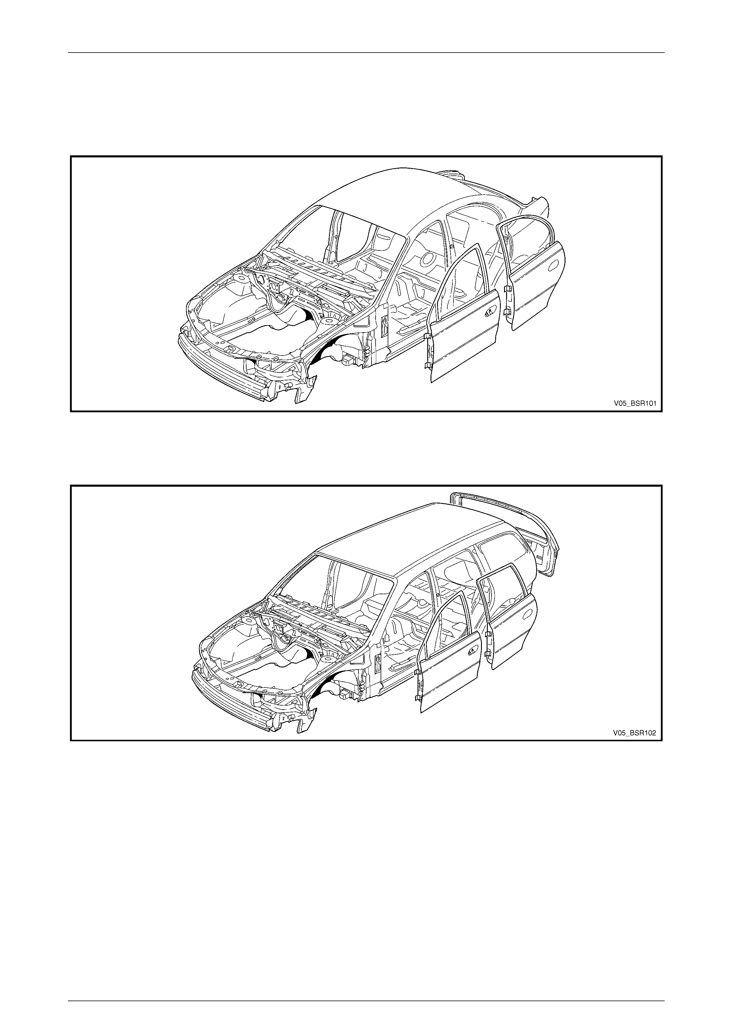
2 Body Components
Sedan
Figure 1 – 1
Wagon
Figure 1 – 2
1 General Information Page 1-4
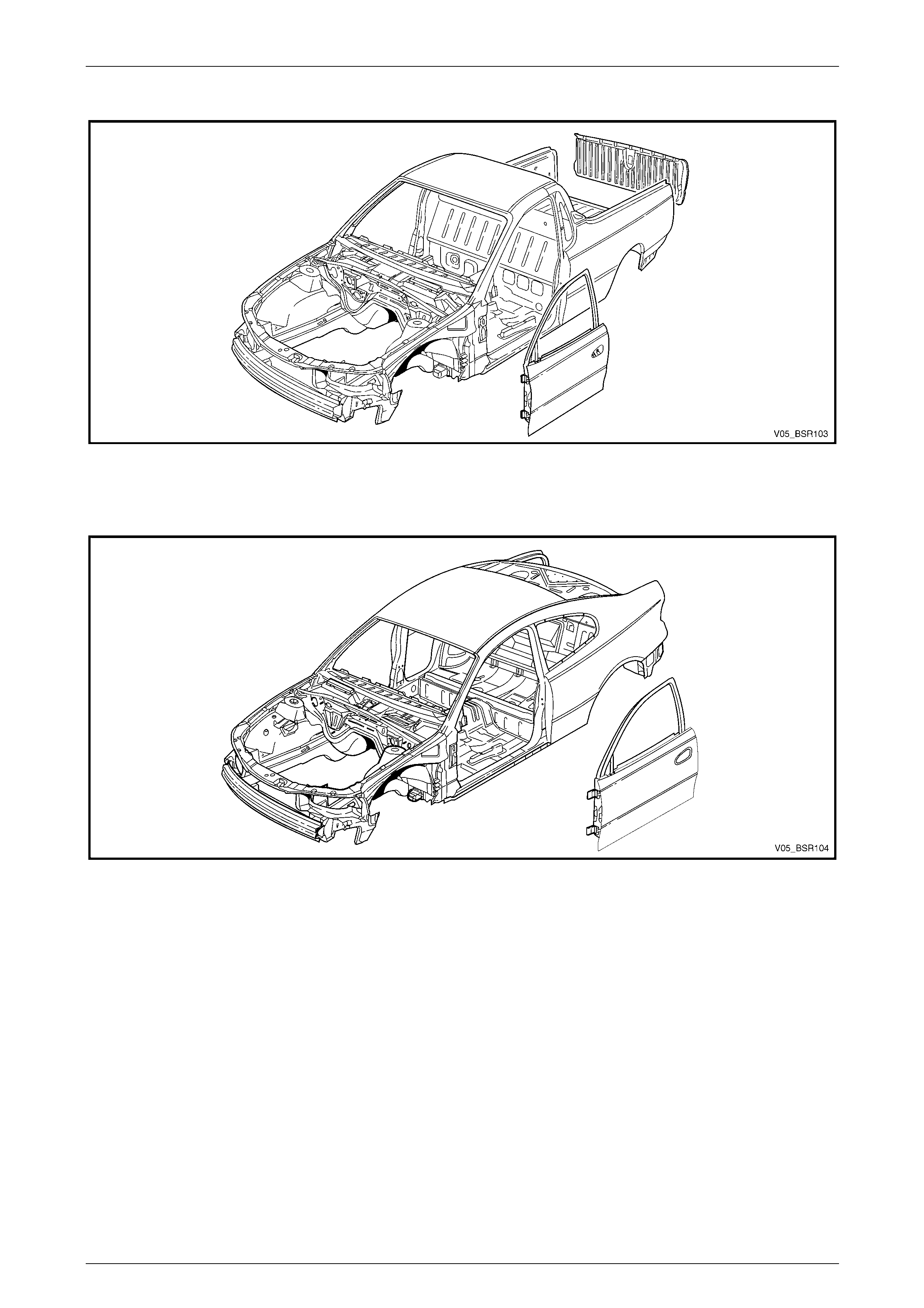
Page 1-4
Utility
Figure 1 – 3
Coupe
Figure 1 – 4

1 General Information Page 1-5
Page 1-5
Regular Cab
Figure 1 – 5
Crew Cab
Figure 1 – 6
1 General Information Page 1-6
Page 1-6
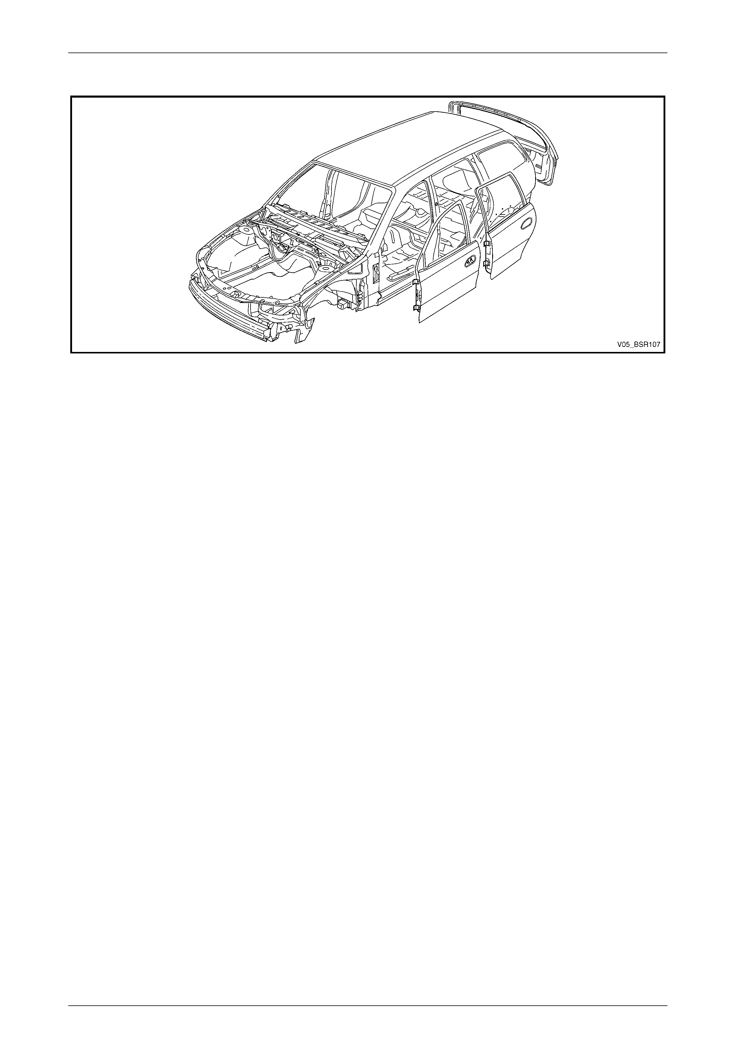
AWD Wagon
Figure 1 – 7
1 General Information Page 1-7
Page 1-7
3 Repair Procedures
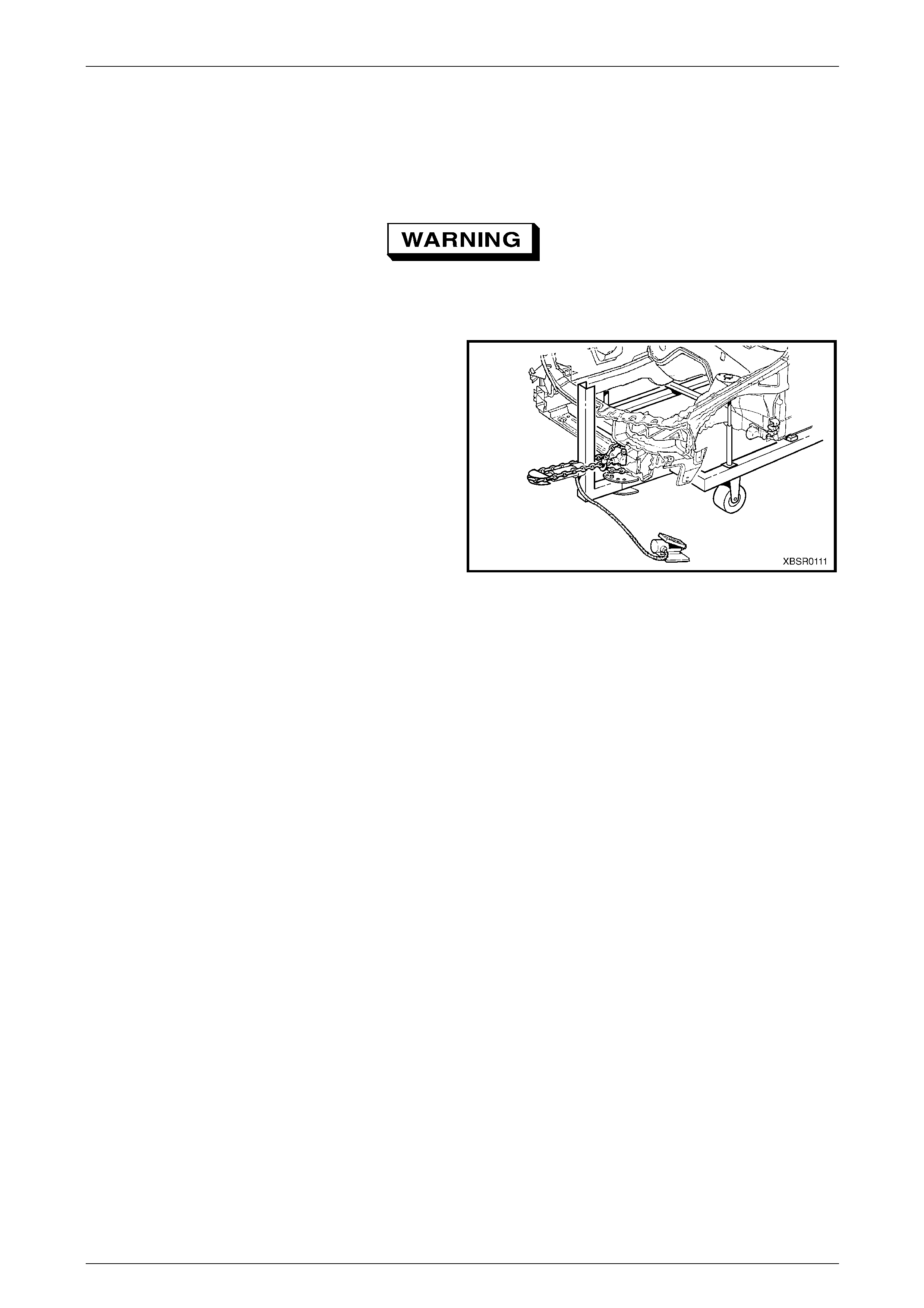
3.1 Frame Straightening
Do not allow personnel to stand in the
direction of the pull. Make use of safety
chains or cables to minimise accidents.
Frame straightening e quipment should be used in itially to
return the vehicle to its approximate shape b efore deta iled
repairs begin. The equipment should be set up in such a
way as to reverse the direction of impact that caused the
damage. The use of an alignment bench with either a jigging
or measuring system is preferred for the real ignment of
vehicles.
Figure 1 – 8
1 General Information Page 1-8
Page 1-8
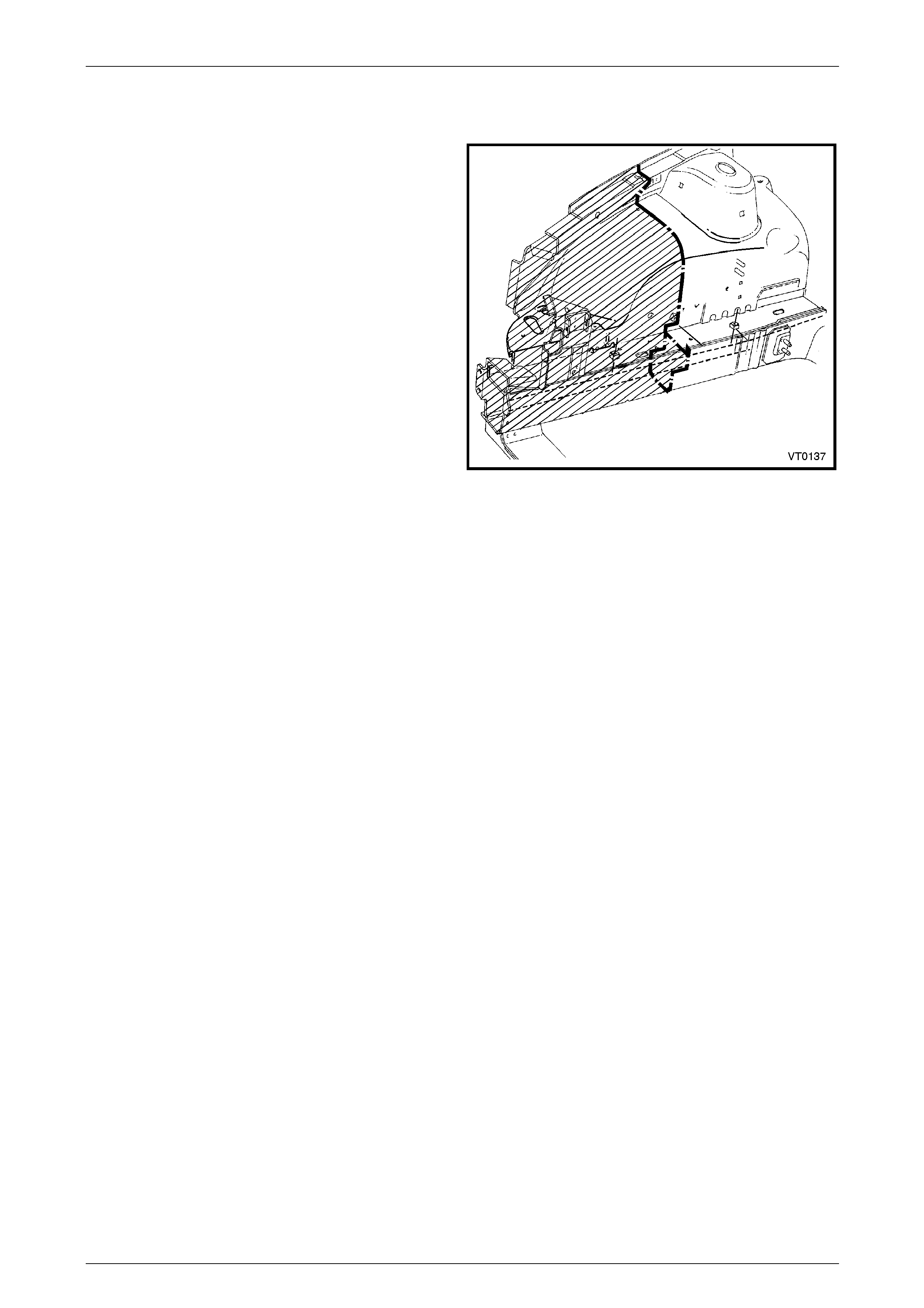
3.2 Rough Cutting
Damaged panels should be rough cut from the vehicle to
make it easier to access and remove spot welds.
NOTE
• Ensure that reinforcement panels are not cut
when the outer panels are being rough cut.
• Check for wiring harnesses, hoses, etc.
behind or inside the panels before performing
any cutting operations.
Figure 1 – 9
1 General Information Page 1-9
Page 1-9
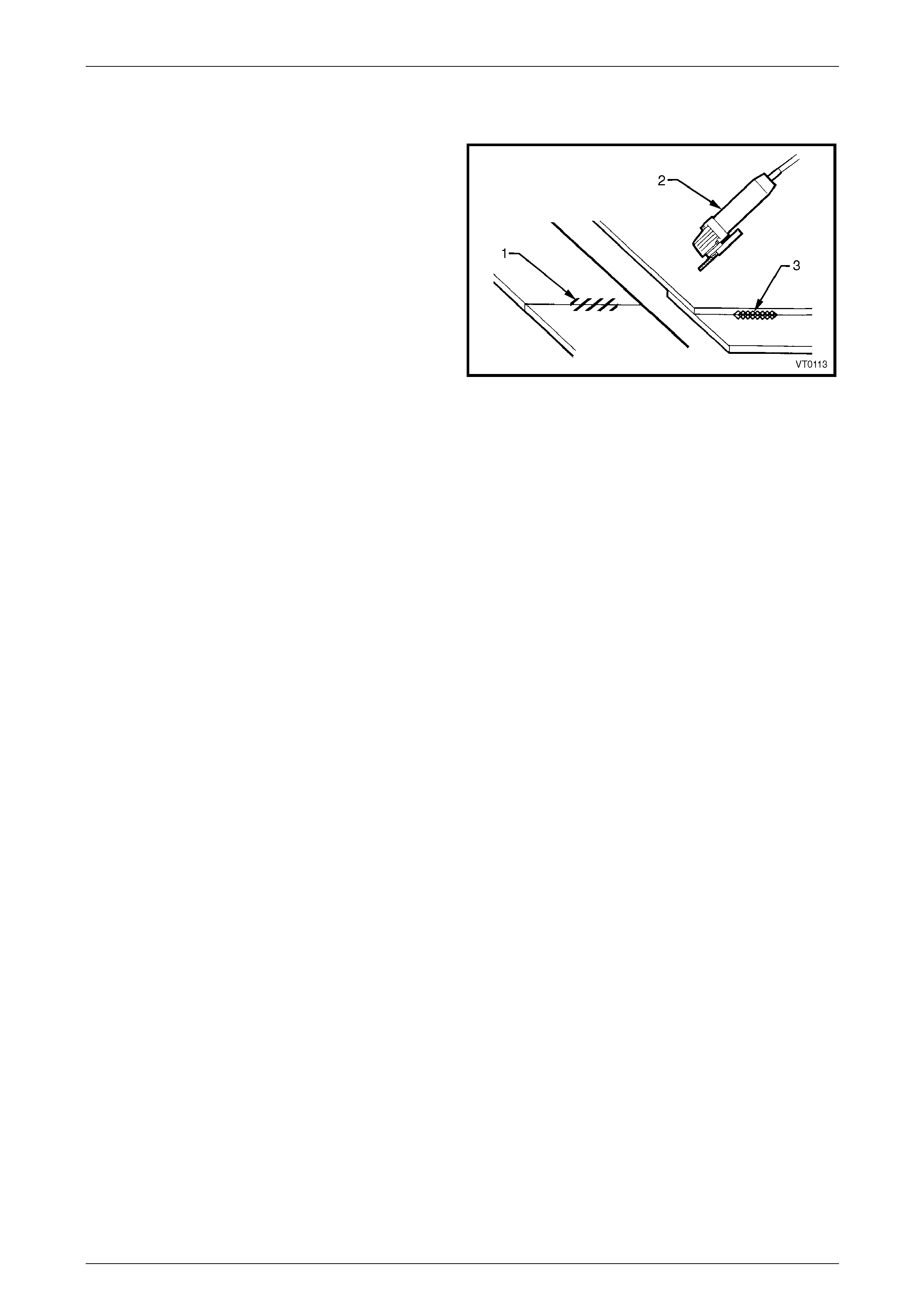
3.3 Cutting MIG Welds
MIG welding is used in various places on the body structure
for additional reinforcement and strength.
MIG welds (1) should be cut with a grinder (2) or power saw.
Where practical, a cross-sectional view of areas that may be
MIG welded over a two panel thickness (3) is shown.
NOTE
• Chiselling MIG welds is not recommended at
any time, as the weld is harder than the
surrounding material, which will tear before
the weld is cut.
• Always take care when grinding or cutting,
not to damage either panels adjoining or
panels below the part being removed. Figure 1 – 10
1 General Information Page 1-10
Page 1-10
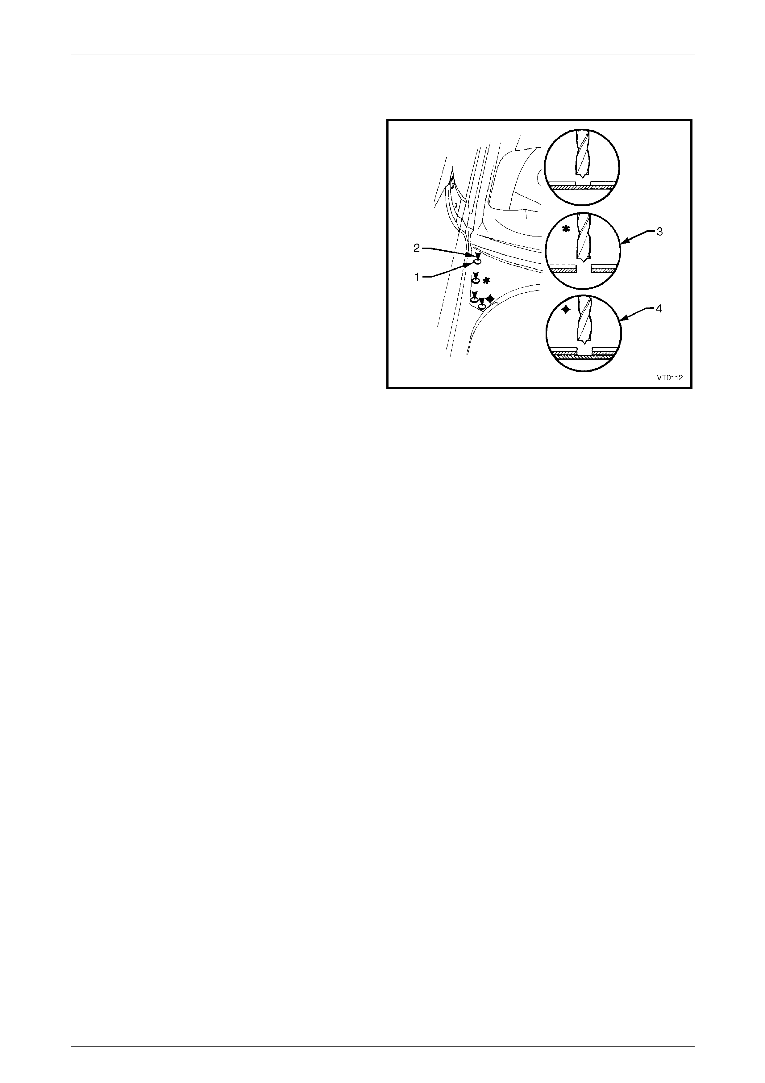
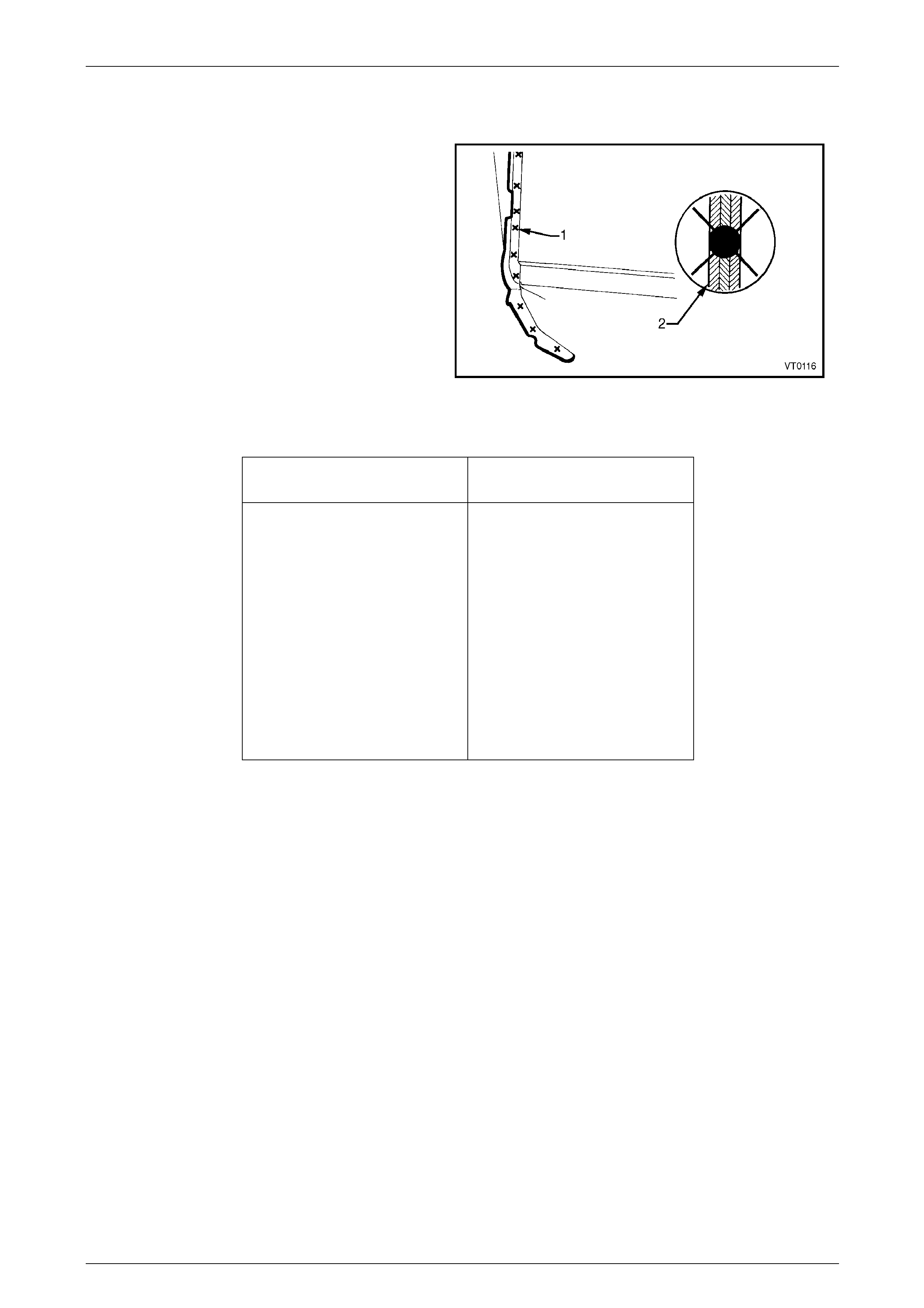
3.4 Spot Weld Cutting
Spot welding is the most predominate method of welding
used on the body structure. Spot welds should be cut using
a suitable spot cutting tool and a low speed drill, preferably
pneumatic.
Before spot cutting, deeply indent the centre of the spot
weld nuggets using a centre punch and hammer. It is
important to accurately indent the centre of the spot weld
nugget to completely remove the weld.
The symbol for spot cutting is a circle (1). The arrows in the
illustrations (2) accompanyi ng each operation proced ure
indicate from which side the spot weld should be cut. Do not
spot cut through both panels unless specified to do so (3).
Repair any holes using a MIG welder.
Where it is necessary to spot cut three or more joined
panels, an encircled area within the accompanying
illustration will indicate the e xtent of the spot cut (4).There
will be some incidents where it is necessar y to chisel
through spot welds rather than spot cut them. Use care
when chiselling to avoid distortion or damage to the
adjacent sheet metal. Figure 1 – 11
1 General Information Page 1-11
Page 1-11
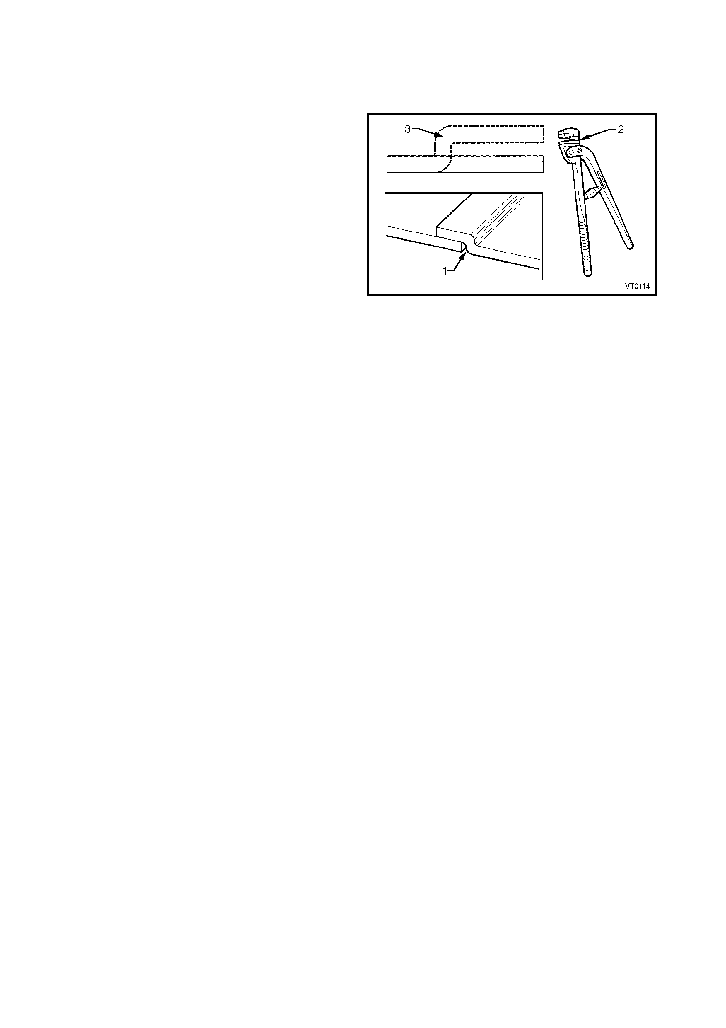
3.5 Lap Jointing
A lap joint (1) is the method of forming an ov er-lapping
seam between two panel sections. This should always be
done with an appropriate tool (2), and care should be taken
to maintain any original curvature of the panel. It may be
necessary the make some incisions at the corners to form
the joint smoothly.
The joggle (3) is the part of the lap joint bein g formed to
over-lap or under-lap the adja cent panel. The joggle should
always be orientated as specified or illustrated.
NOTE
Lap joints should be used wherever possible
when partially replacing panels because of the
additional strength this method provides. Figure 1 – 12
1 General Information Page 1-12
Page 1-12
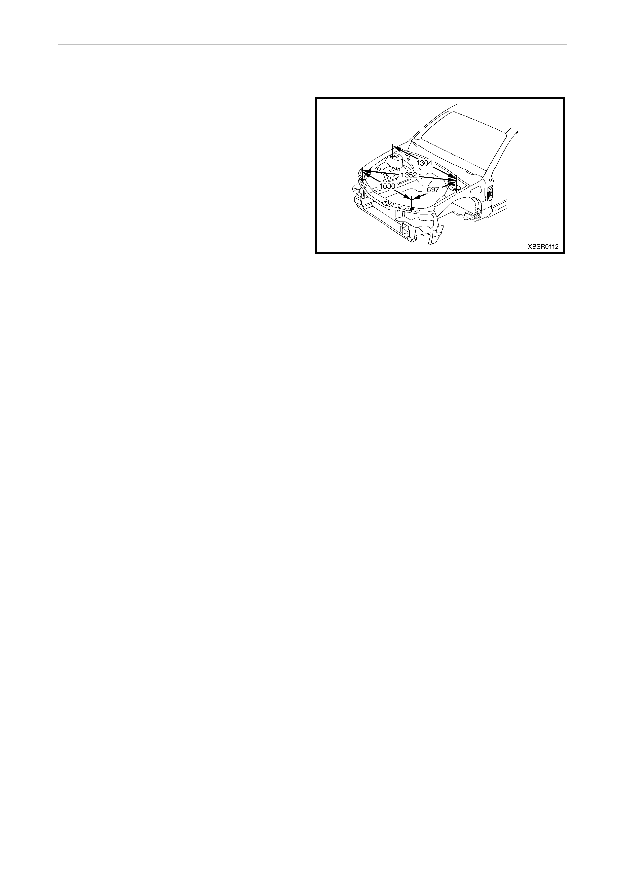
3.6 Repairing the Body Alignment
At all times when repairing the vehic le, use a suitable jigging
or measuring system and utili s e any tooling which is either
specified or deemed necessary to maintain the body
alignment.
Check the alignment of the body using the charts in 3 Bo dy
Construction. The upperbod y dimensions shown are point to
point in a direct line.
The underbody dimensions are projected; the measuring
points are transposed onto a two dimensional (flat) surface
and the measurements are taken along the one plane.
All dimensions are in millimetres unless otherwise specified.
NOTE
Always check the body align ment before welding
panels in position.
Figure 1 – 13

1 General Information Page 1-13
Page 1-13
4 Weld Repair Methods
4.1 General Information
• Always take care when welding. Look
behind the parts being welded to avoid
additional damage or possible fire.
• Flammable materials are used in the
vehicle, always take care to avoid fire
when welding.
Spot welding is the preferred method for attaching of panels and should be used whenever possib le.
This Supplement indicates where spot welding is practical in repair conditi ons using portable spot welding equ ipment.
One repair weld shall be added for each sp ot weld being repaired, by using either a spot weld or a plug weld.
Spot welding is not only faster and more efficient than other weldin g processes, but also causes less rust formation,
reduces the amount of refinishing and causes little distortion to the panel due to heat.
Where the spot welding equipment is not available, or it will not access the required weld position, a plug weld should be
performed. MIG welding should be used for plug welding and also for fusion welding when required.
Gas welding (oxy / acetylene welding) should be avoid ed as a method of repair. The heat generated in makin g the fused
joint causes both a decline in the strength of the areas surrounding the welded parts, and also introduces a high
possibility of warping.
Also refer to 4.5 Welding Legend in this Section.
1 General Information Page 1-14
Page 1-14
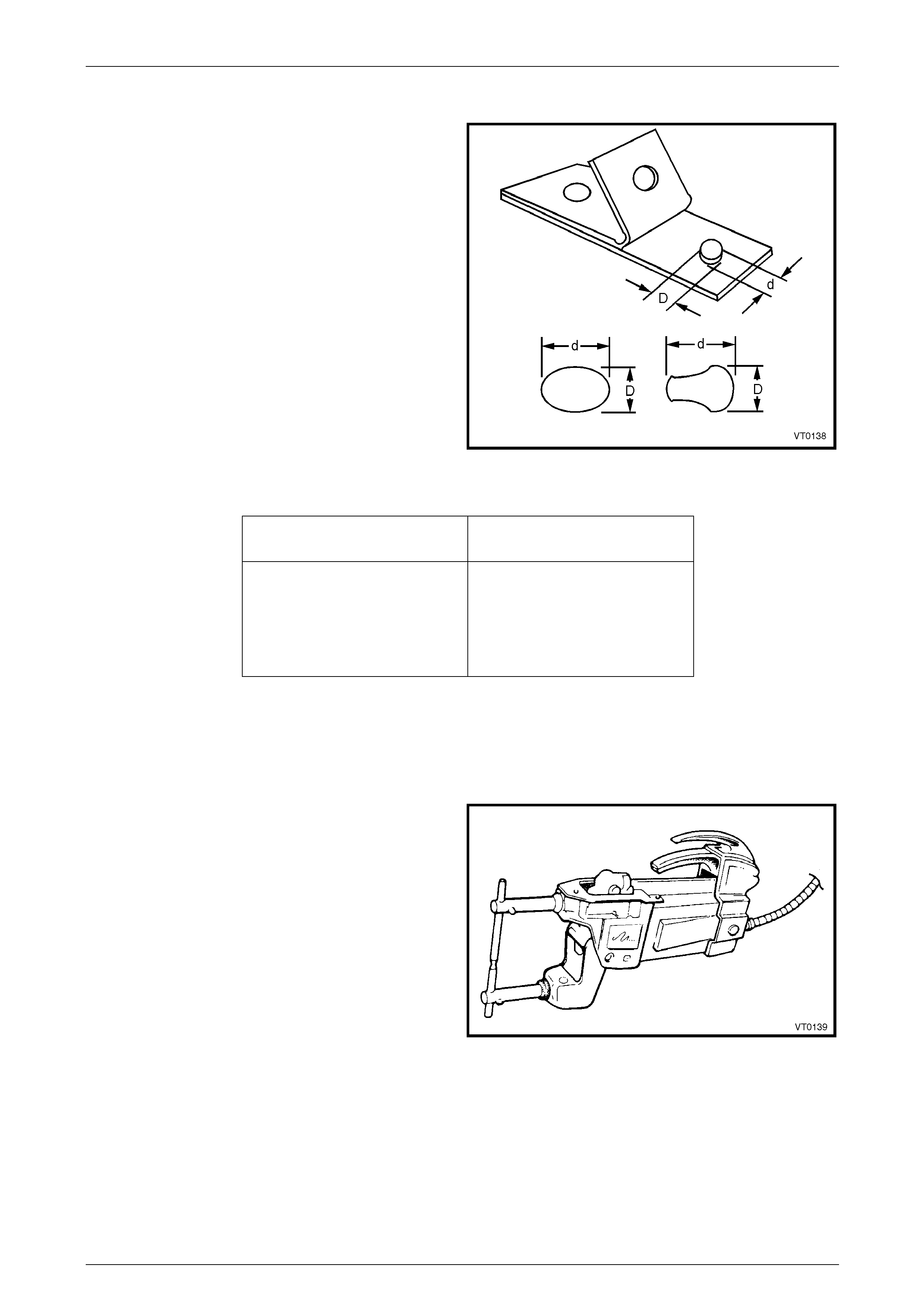
4.2 Spot Welding
Spot Welding (or electric resis t ance spot welding) is a
method of fusing metal parts together over a small area.
Two or more metal sheets are positioned between two
electrodes (weld tips) where p r essure and a large current
are applied. Due to the electrical resista nce of the metals,
a large amount of heat is locally generated causing the
metals to fuse together.
As a guide for weld tip selection and for the
recommended minimum spot weld diameter, the repairer
should refer to Table 1 bel ow. The recommended
minimum spacing bet ween spot welds is provided in
Table 2.
The symbol for spot welding is an " X " (1). Where multi-
ply panels are involved, they will be identified as shown
(2). Figure 1 – 14
Governing Metal Thickness
(GMT) (mm) Minimum Average Diameter o f
Button at Faying Plane (mm)
0.40 – 0.59 3.0
0.60 – 0.79 3.5
0.80 – 1.39 4.0
1.40 – 1.99 4.5
2.00 – 2.49 5.0
2.50 – 2.99 5.5
3.00 – 3.49 6.0
3.50 – 3.99 6.5
4.00 – 4.50 7.0
Table 1
1 General Information Page 1-15
Page 1-15
NOTE
• To determine the minimum weld size for a
two metal stack, use the metal thickness of
the thinner of the two sheets, called the
Governing Metal Thickness (GMT), when
referring to Table 1. When three or more
sheets are being welded, the second thinne st
metal thickness in the total stack up will
determine the minimum weld size for each
pair of contacting sheets where fusion is
required.
• Nominal sheet thickness is used to determine
GMT.
• Average button (nugget) diameter = (D+d)/2.
• Faying Plane. The mating surface of a sheet
which is in contact with or in close proximity
to another sheet to which it is to be joined.
Figure 1 – 15
Governing Metal Thickness
(GMT) (mm) Minimum Spot Weld Spacing
Centre to Centre (mm)
0.7 – 0.9 12.0
1.0 – 1.4 22.0
1.6 25.0
1.8 28.0
Table 2
The efficiency of the spot welding operations during the re pair will control the strength and durability of the finished
vehicle. It is recommended the following poi nts be ad hered to in order that a high quality of welding is ac hieved.
Spot Welder
1 The spot welding machine should be adjusted for the
minimum length of arm appropriate to the particular
weld, so that maximum clamping pressure is available.
2 The electrode tips sho uld be aligned to be parallel and
on the same axis to maintain maximum pressure and
weld alignment.
3 The correct welding tips should be employed as per
Table 1 on the previous page.
Figure 1 – 16
1 General Information Page 1-16
Page 1-16
Panel Condition
1 The panel surface must be free of paint film, rust, dirt and other contaminates so that current flow will be sufficient
for proper fusion.
2 The mating surfaces should be prepare d so there ar e no gaps between the surfaces. Current flow is reduced
considerably by poor contact.
3 All mating surfaces must be treated with a weld through prim er to prevent corrosion in this inaccessible area. The
correct primer has high conductivity to facilitate the weld. Refer to Section 3 Body Construction in this Supplement.
Number of Welds
1 The same number and similar position of spot welds
should be used when replacing the panel, as was
used during manufacture. It is important to maintain
the original structural strength of the vehicle,
particularly because of the implications in deploym ent
of the SRS system. Refer to Section 2 Precautions in
this Supplement for further information on the SRS.
2 The required spot weld diameter is specified in
Table 1, earlier in this Section.
3 Spot welding too closely spaced weakens the welds
due to the shunt effect of the current. Apply a non-
sequential welding procedure.
Figure 1 – 17
Weld Testing
1 Prior to welding, two (or more) pieces of same
thickness panel should be test welded, using the
intended weld settings. The weld should then be
destroyed by twisting the pieces. If the settings are
correct, there should be a weld button (nugget) pulled
out of one test piece with the dimensions
recommended. If not, the weld settings must be
adjusted, and the test repeated.
2 Completed weld sections may be tested usin g a
hammer and chisel (or flat bladed screwdriver). The
testing should cease once the size of the nuggets can
be determined, and the welds should still be intact.
NOTE
The test section must be returned to the correct
shape after testing.
Figure 1 – 18
1 General Information Page 1-17
Page 1-17
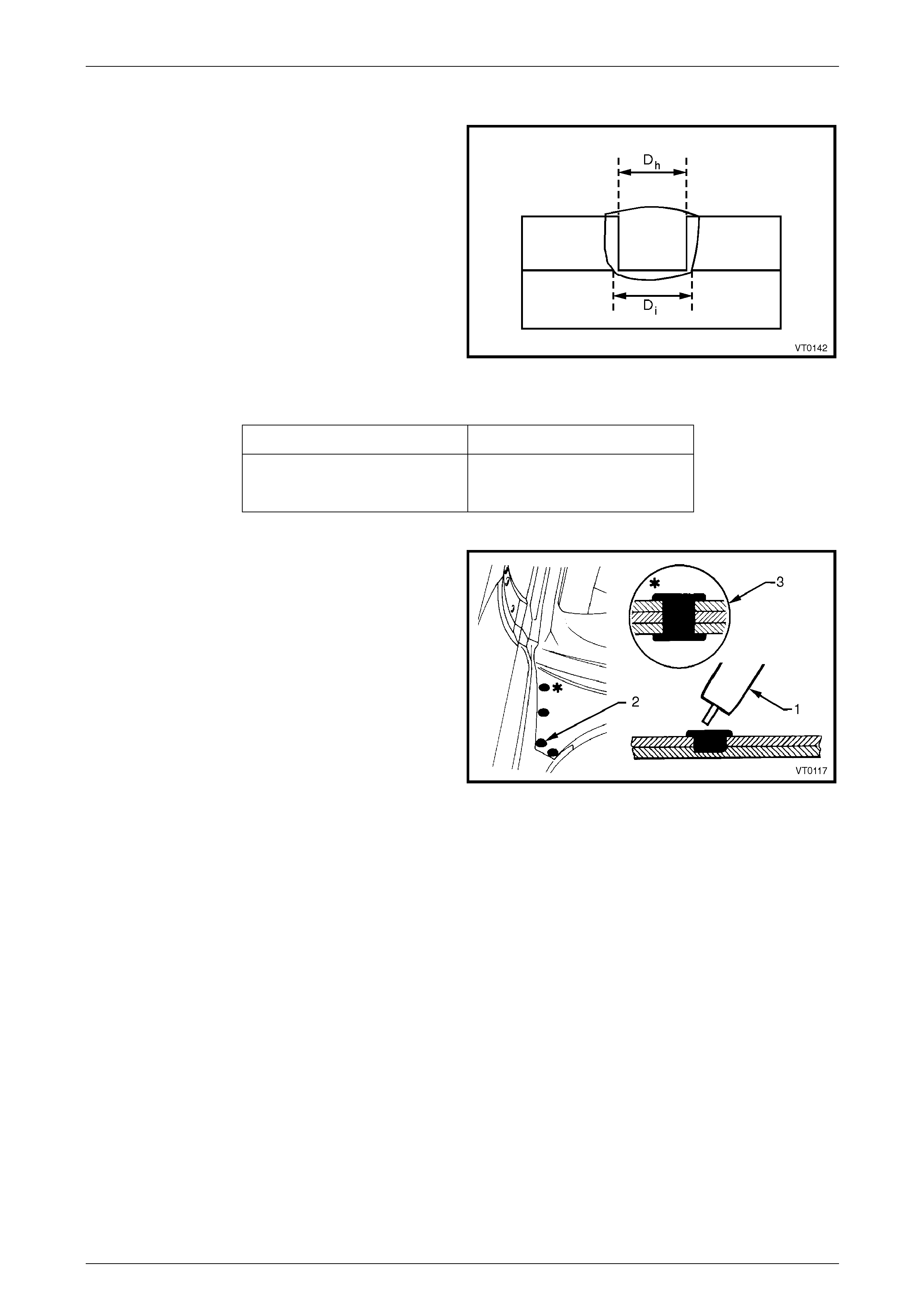
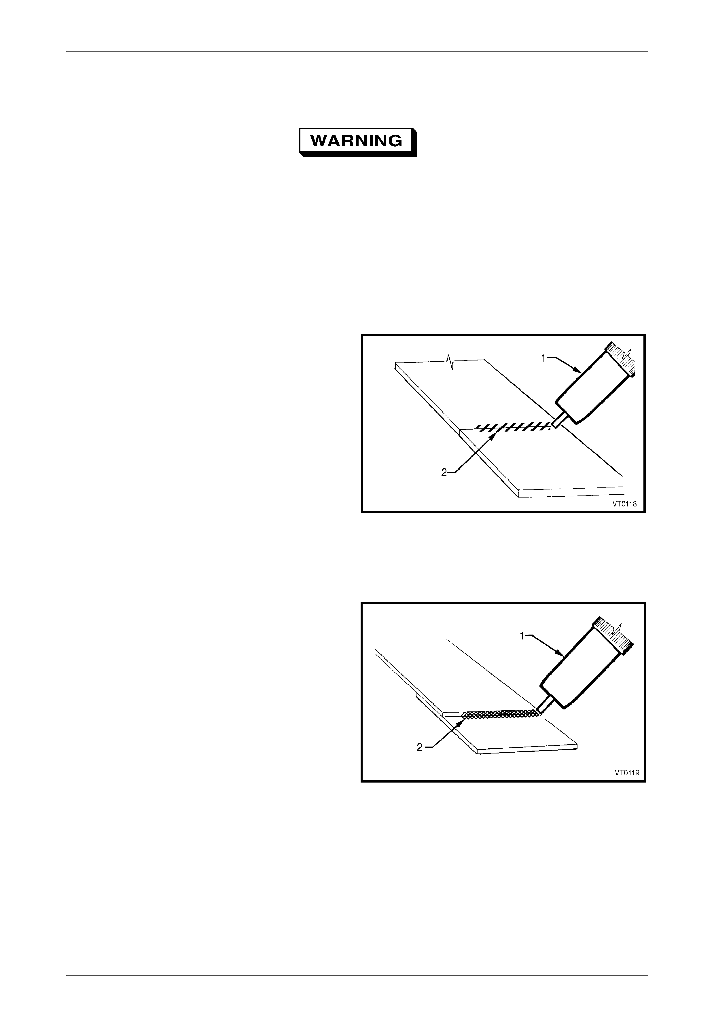
4.3 Plug Welding
In this Supplement, plug welding describes a weld made
inside a pre-drilled hole in one panel of a lap joint, fusing
that panel to the other in the joint.
Plug welding should be performed using a MIG welder of
suitable capacity. The hole is filled with a puddle of MIG
weld, ensuring penetration into the panel below.
The weld interface diameter, Di must be at least equal to the
hole diameter, Dh. The nominal ho le diameters are given in
Table 3.
Figure 1 – 19
Top Sheet Thickness (mm) Nominal Hole Diameter (mm)
0.40 – 1.0 6.0
1.0 – 2.0 8.0
Table 3
For plug welds with a top sheet thickness less than 2 mm,
the welds shall be at least filled to the surface at the hole
circumference. For a thickness greater tha n 2 mm, all plu g
welds shall be filled to at least 2 mm or 90% of the top sheet
thickness (whichever is larger) at the hole circumference,
unless otherwise specified.
Plug welding is best performed with a MIG welder (1) of
sufficient capacity. The required holes, as recommended in
Table 3, are drilled in the appropriate panel which is secured
in position using clamps.
The weld setting and wire gauge are at the discretion of the
operator, and therefor e only qualified individuals should
perform welding tasks during repairs.
The symbol for plug welding is a solid black dot (2) and the
plug welding of multi-ply panels will be identified as shown
(3).
Figure 1 – 20
1 General Information Page 1-18
Page 1-18
4.4 Fusion Welding
Always take care when welding. Look behind
the parts being welded to avoid additional
damage or possible fire. Use an assistant for
this purpose if required.
Fusion welding is a welding method in which the metals to be joined are raised to a molten state and fused together.
Molten filler metal may also be depos ited at the point of welding to fuse with the base metal/s.
Fusion welding repairs should be performed using a MIG welder. Both butt and lap joint methods are utilis ed, as
specified in the repair proced ures.
Butt Welded Joints
Joining two panels together o n the same plane is butt
welding. There shoul d be no gaps between the adjoi ning
edges, so that a strong weld is obtained.
A MIG welder (1) should be used for butt welding, as it
provides localised heat in comparison to other forms of
welding (especially in comparison to gas weldin g). This
localisation of heat significantly reduces panel deformation.
An industrial MIG welder of sufficient capacity must be used
in order to obtain the correct weld penetration and maintai n
the strength and integrit y of the structure.
The weld settings and the wire gauge are at the discr etion of
the operator and therefore only qualified ind ividuals should
perform the welding tasks on repairs.
The symbol used in this Supplement for butt welding is
shown (2).
Figure 1 – 21
Lap Welded Joints
Where panels overlap or are placed together with flat
surfaces mating, fillet welding should be used to form this
lap joint. It is important the gap between the surfaces is
minimal, to ensure a satisfactory result.
For the same reasons as outlined previously, a MIG welder
(1) of suitable capacity should be use d for lap welded joints.
The symbol for fillet welding is shown (2).
Figure 1 – 22
1 General Information Page 1-19
Page 1-19
Bronze Welds
Bronze welding is used to complete the lock pillar join of the rear quarter panel to the door opening frame assembly on
Coupe vehicles, refer to Section 7D Body Side – Coupe.
Other than for the aforementioned, bronze welding should not be used in vehicle repair procedures as it is not
considered strong enough for the welding of body sections or panels.
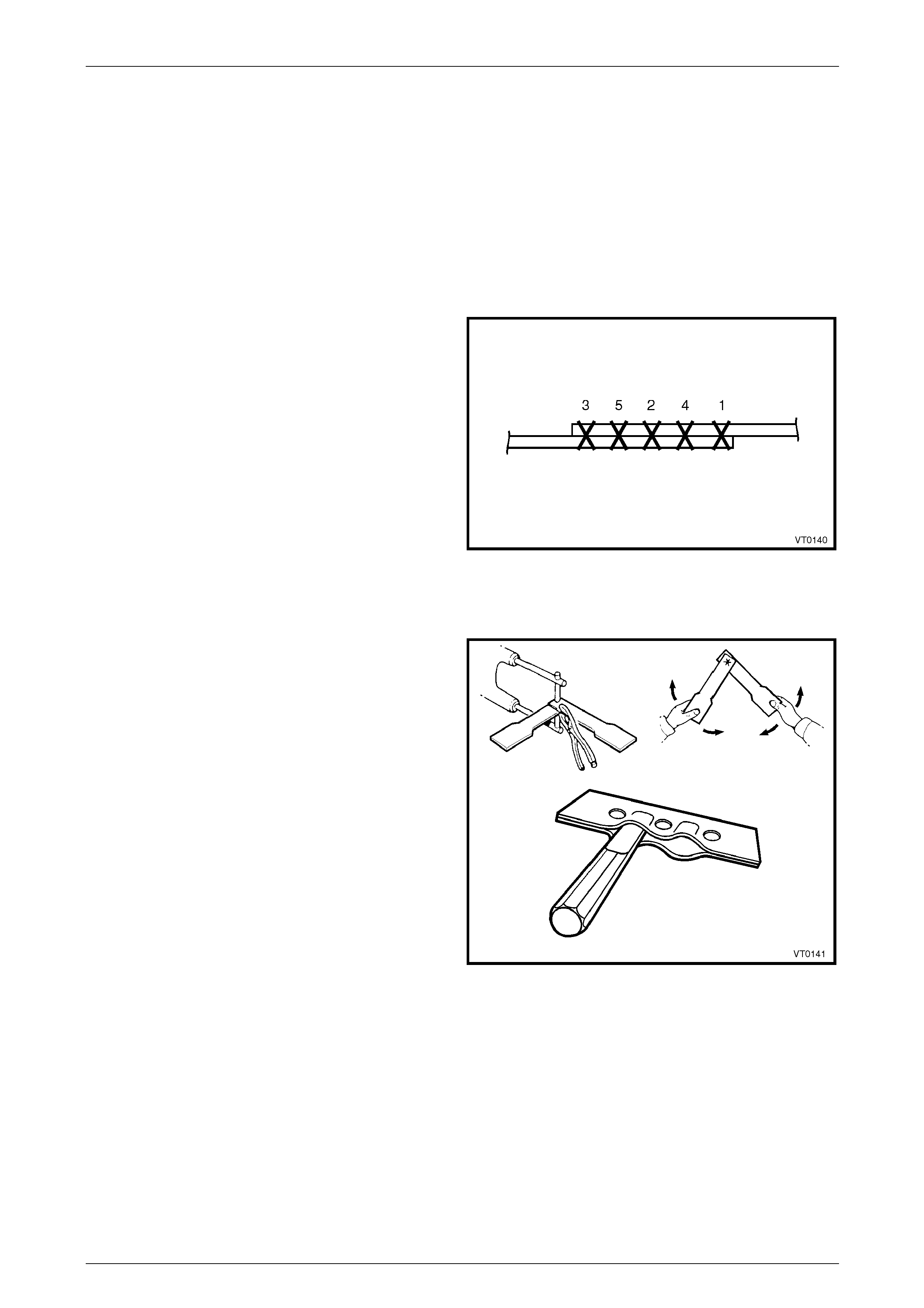
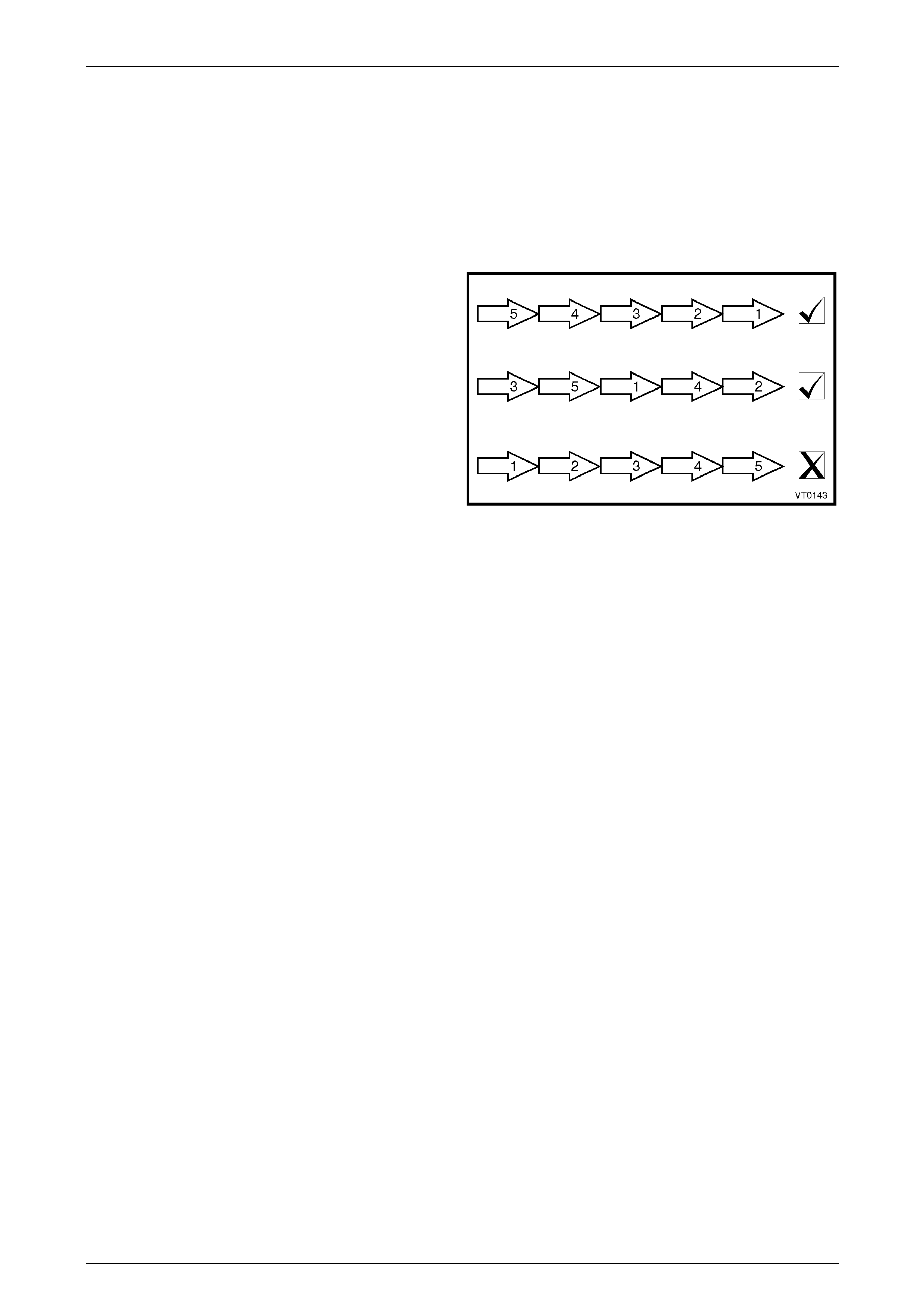
Warp Prevention on Long Welds
A long continuous weld is like ly to cause warping and
residual stresses. Various weld sequences can be utilised to
minimise this effect when long sections of weld are required.
Figure 1 – 23
1 General Information Page 1-20
Page 1-20
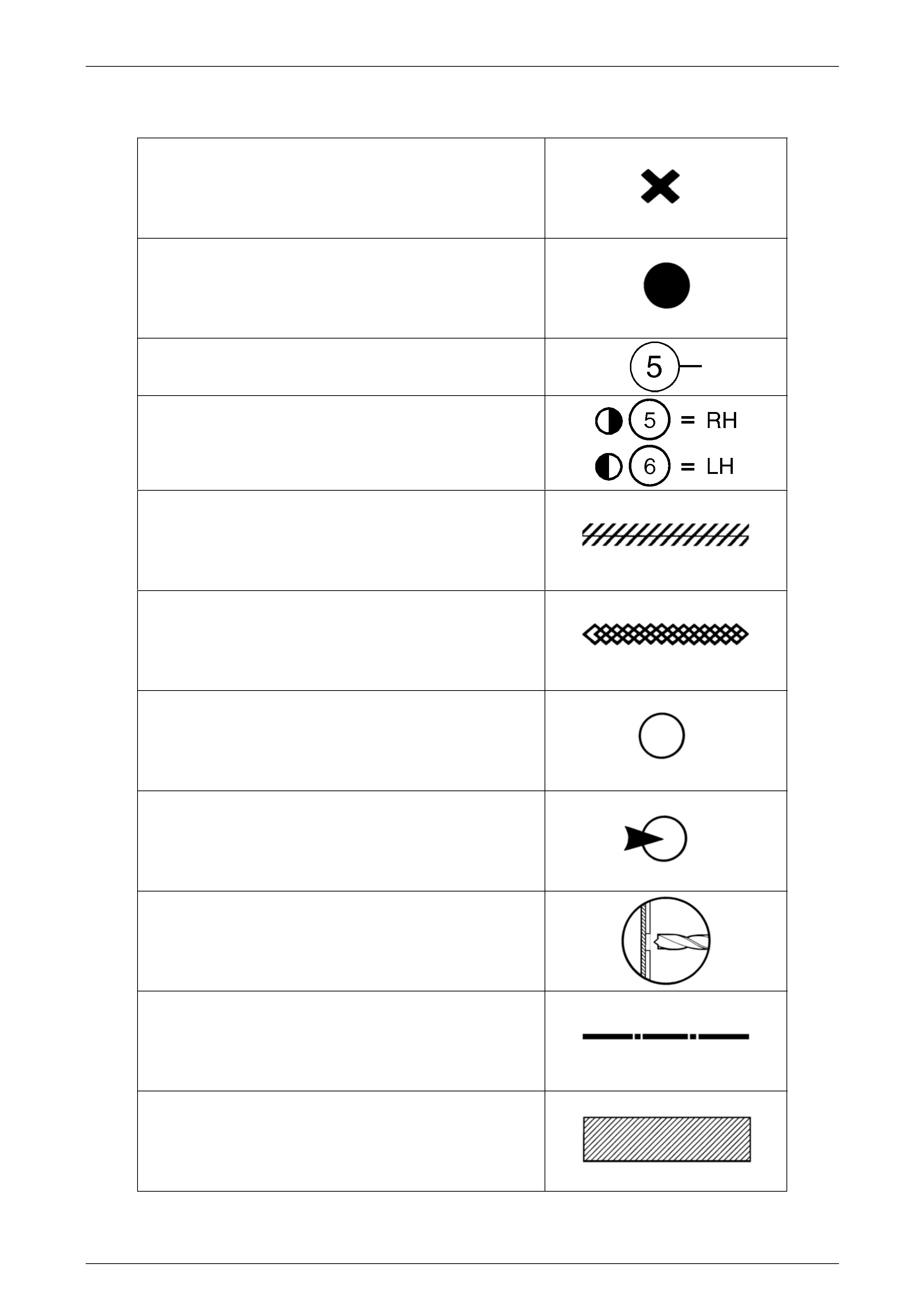
4.5 Welding Legend
Spot welding
Plug welding
Number of welds
Number of welds (or drills) on each side of the vehicle
Butt welding
Fillet welding
Spot Weld to be cut
Spot cut from this side
Spot cut to the depth indicated
Cut the panel along the line shown
Discard this portion