
2 Precautions Page 2-1
Page 2-1
Section 2
Precautions
ATTENTION
Before performing any service operation or other procedure described in this Section, refer to Section 00
Warnings, Cautions and Notes in the MY2005 VZ Service Information for correct workshop practices with
regard to safety and/or property damage.
The structure of the body shell has been
developed using complex design and
development techniques. In addition to
meeting all required standards, the vehicle
body is also a critical part of the overall safety
systems. It is therefore imperative the repair
procedures described here are adhered to
during all vehicle body repairs.
1 General Description ...............................................................................................................................3
2 Personal Safety Precautions.................................................................................................................4
2.1 Protective Gear ...................................................................................................................................................... 4
2.2 Flammable Materials.............................................................................................................................................. 5
2.3 Fuel Tank................................................................................................................................................................ 6
2.4 Workshop Precautions.......................................................................................................................................... 7
2.5 Vehicle Stability Precautions................................................................................................................................ 8
2.6 Dash Panel Precautions........................................................................................................................................ 9
2.7 Air-conditioning System ..................................................................................................................................... 10
3 General Precautions ............................................................................................................................11
3.1 Cutting Locations ................................................................................................................................................ 11
3.2 Dash Panel Assembly.......................................................................................................................................... 12
3.3 Steering System................................................................................................................................................... 13
3.4 Discharging The Fuel Lines................................................................................................................................ 14
4 Occupant Protection System Precautions ........................................................................................15
4.1 Repairs To Vehicle Structure.............................................................................................................................. 16
4.2 Repairs And Inspections Required After A Collision ....................................................................................... 17
4.3 System Disabling And Enabling Procedure ...................................................................................................... 18
Disabling the OPS................................................................................................................................................ 18
Enabling the OPS................................................................................................................................................. 18
4.4 OPS Safety Precautions...................................................................................................................................... 19
5 Electrical Precautions..........................................................................................................................20
5.1 Electronic Devices............................................................................................................................................... 20
5.2 Before Repairing The Vehicle............................................................................................................................. 21
Paint Ovens.......................................................................................................................................................... 21
Welding................................................................................................................................................................. 21

2 Precautions Page 2-2
Page 2-2
6 Jacking Precautions ............................................................................................................................22
Sedan, Wagon, Utility, Coupe and AWD Wagon ............................................................................................... 22
Regular Cab.......................................................................................................................................................... 23
Crew Cab .............................................................................................................................................................. 23
7 Towing Precautions .............................................................................................................................24
7.1 Towing On Four Wheels...................................................................................................................................... 24
7.2 Towing On Two Wheels....................................................................................................................................... 25
8 Plastic Components.............................................................................................................................26
8.1 Common to all Vehicles ...................................................................................................................................... 26
Exterior............................................................................................................................................................. 26
Interior.............................................................................................................................................................. 29
8.2 Sedan Unique....................................................................................................................................................... 31
Exterior............................................................................................................................................................. 31
Interior.............................................................................................................................................................. 31
8.3 Wagon Unique...................................................................................................................................................... 32
Exterior............................................................................................................................................................. 32
Interior.............................................................................................................................................................. 32
8.4 Utility Unique........................................................................................................................................................ 34
Exterior............................................................................................................................................................. 34
8.5 Regular Cab Unique............................................................................................................................................. 35
Exterior............................................................................................................................................................. 35
8.6 Crew Cab Unique................................................................................................................................................. 37
Exterior............................................................................................................................................................. 37
8.7 Coupe Unique....................................................................................................................................................... 39
Exterior............................................................................................................................................................. 39
8.8 AWD Wagon Unique............................................................................................................................................ 40
Exterior............................................................................................................................................................. 40
8.9 Plastic Types........................................................................................................................................................ 41
9 Special Steel Precautions....................................................................................................................42
9.1 Pre-Coated Steel.................................................................................................................................................. 42
9.2 Re-phosphorised Steel........................................................................................................................................ 43
9.3 High Strength Low Alloy Steel............................................................................................................................ 44
10 Cavity Foam..........................................................................................................................................46
Sedan and Wagon................................................................................................................................................ 47
Utility..................................................................................................................................................................... 48
Coupe.................................................................................................................................................................... 49
10.1 Cavity Foam – Replace........................................................................................................................................ 50
Hinge Pillar........................................................................................................................................................... 50
Centre Pillar, Sedan and Wagon......................................................................................................................... 50
Centre Pillar, Utility.............................................................................................................................................. 51
Centre Pillar, Coupe............................................................................................................................................. 51
Lock Pillar, Sedan................................................................................................................................................ 52
Lock Pillar, Coupe................................................................................................................................................ 52
Body Lock Pillar, Utility....................................................................................................................................... 53
Rocker Panel, Utility............................................................................................................................................ 53

2 Precautions Page 2-3
Page 2-3
1 General Description
This Section contains important information regarding the precautions that are to be observed when performing repair
work.
The reasons for these precaut ions are threefold:
• Firstly, it is important the safety of those repairing the vehicle is not compromised.
• Secondly, it must be ensured that inadverte nt damage is not caused to the vehicle during the preparation for, or
during the performance of, repairs to that vehicle.
• Finally, it must be ensured that any relevant Federal an d State legislation is abided by.

2 Precautions Page 2-4
Page 2-4
2 Personal Safety Precautions
2.1 Protective Gear
Protective clothing should be worn at all times when automotive body repa ir work is being carried out. The appropriate
safety gear will vary in accordance with the work being performed an d includes:
• work overalls,
• dust mask,
• safety shoes,
• work gloves,
• welding mask,
• ear muffs,
• safety glasses and
• leather apron.

2 Precautions Page 2-5
Page 2-5
2.2 Flammable Materials
It is extremely important to keep the work areas clear of flammable materials. Flammable materials such as adhes ives,
solvents and paints are regularly used in the repair i ndustry. T heir proximity creates a problem where ignition sources
such as grinding sparks and welding flames and sparks are regularly present.
All flammable chemicals shoul d be kept i n appropriate storage cabinets.
Be sure to abide by local law s and regulations
regarding the storage of hazardous materials.

2 Precautions Page 2-6
Page 2-6
2.3 Fuel Tank
Keep all naked flames and sparks away from
the vehicle if you can smell fuel vapour.
Extreme care must be exercised when using
an oxy/acetylene to rch.
Welding, grinding or drilling near the fuel tank is dangero us. If a vehicle ha s been involved in a collision, fuel may be
leaking from the tank, lines or unions.
If repairing the underbody, or any rear p art of the vehicl e, the fuel tank sh ould first be removed to avoid fire and possible
personal injury.
Be aware that grinding or cutting the fuel pipes may cause fire. For the procedure to discharge the fuel li nes refer to
3.4 Discharging The F uel Lines.

2 Precautions Page 2-7
Page 2-7
2.4 Workshop Precautions
The process of welding produces fumes which if inhaled may have short or long term he alth effects.
Welding metals containing certain alloys, are galvanised, or are specially treated may increase the health risk.
While the risks to the body repairer are slight, it is imperative that any welding is performed in a well-ventilated area.
Where it is not possible to ensure good ve ntilation, a suitable respirator should be worn.
The body structure of consists of metal compone nts made from:
• mild steel,
• mild steel with Galvaneal coating – two sides,
• mild steel with Zinc coating – two sides, and/or
• mild steel with Zinc-nickel coating – one and two sides.

2 Precautions Page 2-8
Page 2-8
2.5 Vehicle Stability Precautions
To avoid personal injury occurring, the following precautions should be observed:
• Secure the vehicle on safety stands; never work below a vehicle supported only by jacks.
• Frame straightening e quipment can be dangerous; always use in strict ac cordance with the manufacturer’s
recommendations.

2 Precautions Page 2-9
Page 2-9
2.6 Dash Panel Precautions
The silicone adhesiv e used in the glue track, once cured, requires no special precautions. However, when mixing the
adhesive compound with the catalyst, the precautions listed below should be observed.
• The catalyst is a toxic substance and must not be swallowed. Keep the catalyst out of reach of children.
• Wear safety glasses to avoid contact with the eyes. If eye contact occurs, wash the area in clean water only, and
seek immediate medical advice.
• Wear protective gloves when handing the adhesiv e and catalyst as they can cause skin irritation.
• If irritation occurs, wipe the adhesive/catalyst off using a clean cloth and then wash the affected area thoroughl y in
clean water.
• As the vapour produced by the catalyst may cause breathin g difficulties, use only in a well ventilated area.
• Since the catalyst is combustible, keep it a way from sparks and flame.

2 Precautions Page 2-10
Page 2-10
2.7 Air-conditioning System
NOTE
As an environmental m easure, Federal and State
legislation requires air-conditioning systems be
discharged in accordance with certain
regulations. It is recommended that you be
acquainted with the requirements.
Care should be taken when discharging th e air-conditioning s ystem to ensure that the refrigerant is not released to the
atmosphere, but recaptured for recycling. Environment friendly refrigera nt R134a is not an ozone depleting substance
but its release would add to the greenhouse warming effect. It is therefore essential that the refrigerant be recovered
using a Refrigerant Recover y Unit (RRU).
Refer to Section 2B HVAC Climate Control – Servicing and Diagnosis in the MY2005 VZ Service Information for
comprehensive procedures o n discharging and refilling the air-conditioning system.
NOTE
R134a and R12 are not compatible and must
never be mixed.
Frostbite will be caused if the refrigerant liquid contacts skin. Always wear safety gloves and goggles and stay clear of
any discharge.
If R134a enters the eye, freezing of the eye could occur a nd could result in blindness. If this situation oc curs, the
following procedure is suggested:
1 Keep calm.
2 Do not rub eyes.
3 Splash large quantities of cool water into the eyes to raise the temperature.
4 Tape a sterile patch in place to prevent dirt from entering the eye.
5 Go immediately to a doctor or hospital.
Do not attempt to treat the condition yourself.

2 Precautions Page 2-11
Page 2-11
3 General Precautions
3.1 Cutting Locations
Do not cut the body structure at any point
other than specified in this Supplement.
The vehicle body structures are designed to meet or exceed all relevant Statutory Regulations. Cutting anywhere other
than specified may compromise the strength of the vehicle and therefore occupant protec tion system operation and
occupant safety.

2 Precautions Page 2-12
Page 2-12
3.2 Dash Panel Assembly
To avoid fire, do not attempt to burn the
remaining sealant from the glue track using
an oxy/acetylene to rch.
The dash panel assembly must be bonded to the body with the correct two-part, fast cure silicone adhesive. It is
important that the dash panel is ready for installation and has been trial fitted before the adhesive is mixed, as the
working time is less than 20 minutes.
Ensure that preparation of the pan el surfac e is completed prior to mixing the adhesive. T his should include painting of
the surrounding areas and thorough cleaning of the glue track.
After installation, the dash panel should not be disturbed u ntil the ad hesive is fully cured (about three ho urs).
Refer to Section 5 Cockpit Module for a full description of the installation procedure for the dash pa nel assembly.

2 Precautions Page 2-13
Page 2-13
3.3 Steering System
Vehicles involved in collisions resulting in major body or sheet metal damage, or where the steering column has been
impacted, may also have a damaged or misa ligned steering column. Refer to Section 9 Steering in the MY2005 VZ
Service Information.

2 Precautions Page 2-14
Page 2-14
3.4 Discharging The Fuel Lines
The fuel rail on the engine may contain up to
one litre of fuel under pressure.
Disconnecting the fuel lines at any point
without relieving the pressure will cause
petrol to be expelled and may cause fire or
injury.
To discharge the fuel lines:
1 Apply the parking brak e.
2 Remove the fuel pump fuse from the engine compartme nt fuse an d relay panel.
3 With the throttle closed, crank the engine.
NOTE
The engine may start and idle, until the fuel
supply remaining in the lines is exhausted.
4 When the engine stops, engage the starter again for a further 10 seconds to ensure dissipation of any remaining
pressure.
5 Turn the ignition switch to the OFF position.
6 Disconnect the fuel lines from the fuel tank, allowing any remaining fuel to drain, and then seal the apertures with
suitable plastic plugs.
7 Drain the contents of the fuel tank.
NOTE
The fuel tank may contain up to 82 litres of petrol.
9 Remove the tank from the vehicle, refer to Section 8A1 Fuel System in the MY2005 VZ Service Information.
10 Seal the fuel tank filler with a plug. Do not use a rag.
2 Precautions Page 2-15
Page 2-15
4 Occupant Protection System
Precautions
The Occupant Protection System (OPS) provides protection additional to the driver and front passenger seatbelts in
three ways:
1 By activating seatbelt pretension ers which tighten the seatbelt dur ing a collision, restricting the occupant’s forward
movement.
2 By deploying a front driver inflatable restraint from the centre of the steering wheel and a front passenger inflatable
restraint (where fitted) from the top left side of the instrument panel pad assembly, during certain frontal collisions.
3 By deploying a side inflatable restraint (where fitted) for the front occupants to offer additiona l protection for the
driver or front passenger during certain side impact collisions.
The Sensing and Diagnostic Module (SDM), located under the front floor conso le, contro ls inflatable restraint and
seatbelt pretensioner deployment. The SDM has the ability to deploy the seatbelt pretensioners only, the pretensioners
and front inflatable restraint or a side inflatable restraint on the side of the vehicle which an impact occurs .
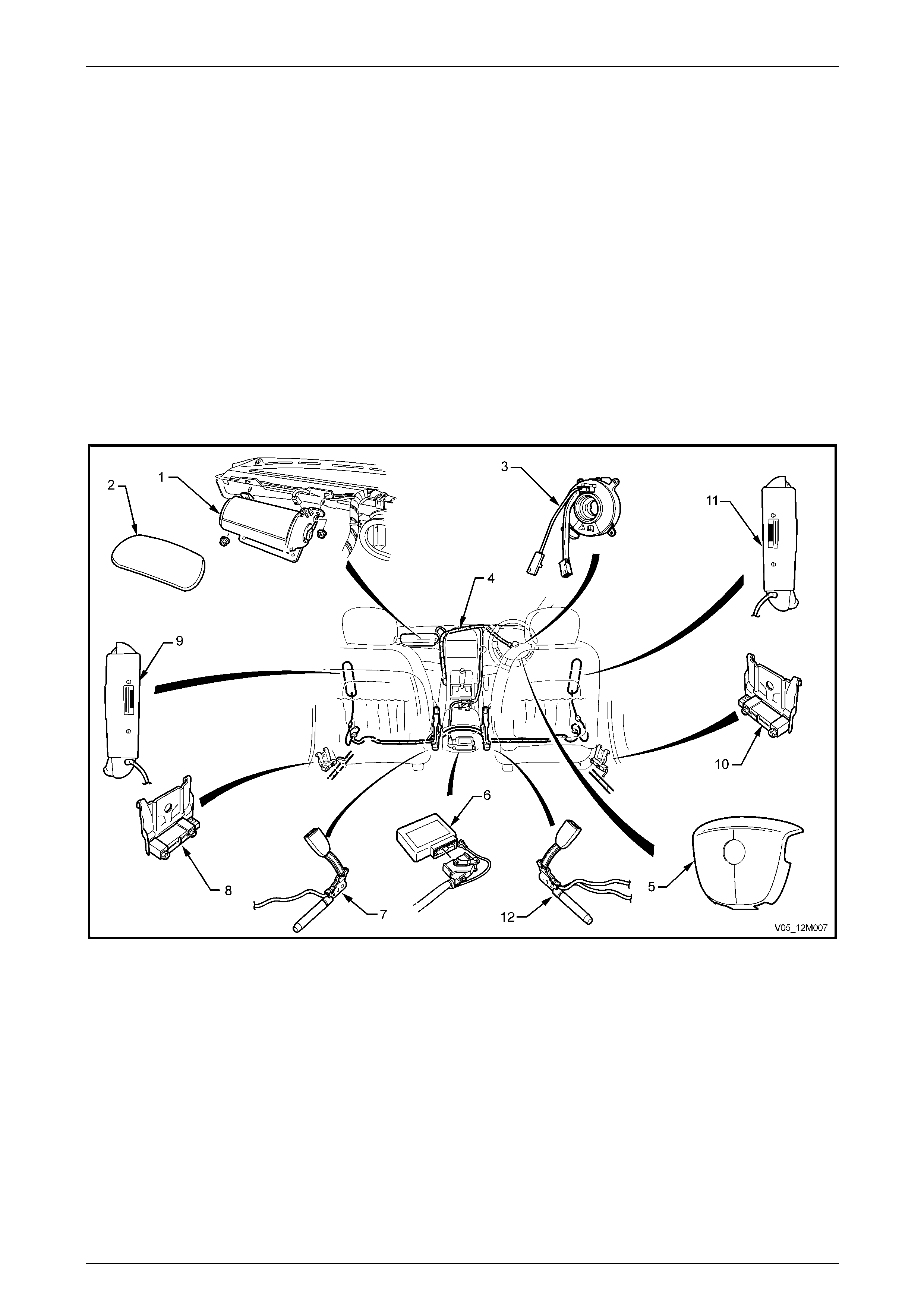
Refer to Figure 2 – 1 for occupant protection system component locations.
Figure 2 – 1
Legend
1 Instrument Panel Inflatable Restraint (passenger airbag)
Assembly
2 Instrument Panel Inflatable Restraint Opening Trim Cover
3 Clock Spring Coil Assembly
4 OPS Wiring Harness (part of front body wiring harness)
5 Steering Wheel Inflatable Restraint (driver airbag) Assembly
6 Sensing and Diagnostic Module (SDM)
7 Left-hand Seat Belt Pretensioner Assembly
8 Left Side-impact Sensor (peripheral acceleration sensor)
9 Left Side-impact Inflatable Restraint (side-impact airbag)
Assembly
10 Right Side-impact Sensor (peripheral acceleration sensor)
11 Right Side-impact Inflatable Restraint (side-impact airbag)
Assembly
12 Right-hand Seat Belt Pretensioner Assembly

2 Precautions Page 2-16
Page 2-16
• Accessory type or after-market bull-bars
or such devices not approved and fitted to
a vehicle with OPS may adversely affect
the vehicle’s desired threshold
characteristics for deployment.
• Accessory and after-market seat covers
must not be fitted to a vehicle with side
inflatable restraints unless approved by
the vehicle manufacturer. Seat covers that
are not approved could greatly inhibit the
performance of the side inflatable
restraint, compromising the occupant’s
safety in the event of side inflatable
restraint deployment.
• Accessory or after-market instrument
panel covers, or the like, must not be
installed. This would greatly inhibit the
performance of the front passenger
inflatable restraint and reduce front
passenger’s safety in the event of an
inflatable restraint deployment.
• Fitting of accessories such as drink
holders, cassette / CD racks, additional
mirrors, etc. are not permitted in the
immediate deployment area of the front
passenger’s inflatable restraint as these
may be propelled towards the occupants
when the airbag is deployed.
4.1 Repairs To Vehicle Structure
Correct operation of the Occupant Protection
System (OPS) requires that any repairs to the
vehicle structure must return it to its original
production configuration.
The procedures to achieve this are in line with those detailed in the rel eva nt Section of th is Supplement.
The integrity of the front side rail assembl ies is critical to the function of the OPS. If the front side rail assemblies are
damaged, or incorrectly repaired following damage, it is possible the OPS will not function as intended, resulting in
incorrect deployment timing and placing the occupant(s) at increased risk of injury.
The following strategy should be used when repairing the front side rail assemblies:
1 If minor damage has occurred to the front of the front side rail assembl y which does not involve significant creasing
or crumple, it may be straightened.
2 If significant creasing or crumple of the front side rail assembly has occurred, but is restricted to the area forward of
the front suspension crossmember, the front side rail assembly may be cut at a point b etween the two
crossmember mounting bolts and a ne w partial section welded in place. For informatio n o n the recomme nded cut
point, refer to Section 4 Front End.
3 If significant creasing or crumple of the front side rail assembly has occurred and continues rearward of the front of
the front suspension crossmember, the full front side rail assembly should be replaced.

2 Precautions Page 2-17
Page 2-17
4.2 Repairs And Inspections Required After
A Collision
Below is listed the components that must be replaced if deployment occurs under the conditions listed. If any OPS
components are damaged, they must be replaced with new parts. If OPS component mounting points are dama ge d, the y
must be repaired or replaced.
NOTE
Never use OPS components from another
vehicle.
The steering wheel must be dimensionally in spected, whether deployment has occurred or not.
Refer to Section 9 Steering, in the MY2005 VZ Service Information.
A collision severe Enough to deploy the seatbelt pretensioners but not the Inflatable Restr aints(s).
Replace the follo wing compo nents:
• Any seatbelt worn during the collision,
• Seatbelt pretensioner/s,
• Front seat guide rail and adjuster assembly (where the seat was occupied in the collision),
• Sensing and Diagnostic Module.
A collision where the seatbelt pretens ioners and front inflatable restraint(s) has deployed.
Replace the components as above in addition to:
• Driver inflatable restraint module,
• Steering wheel,
• Clock spring coil,
• Steering column,
• Instrument panel inflatable restraint module (where fitted),
• Instrument panel pad assembly,
• Instrument panel inflatable rest raint opening trim cover,
• Instrument panel inflatable restraint bracket,
• Instrument panel lower bracket.
A collision where a side inflatable restra int has deployed.
Replace the follo wing compo nents:
• Any seatbelt worn during the collision,
• Relevant side front seat assembly (including the side inflatable restraint module),
• Relevant side impact sensor,
• Sensing and Diagnostic Module.

2 Precautions Page 2-18
Page 2-18
4.3 System Disabling And Enabling
Procedure
Disabling the OPS
The SDM can maintain sufficient voltage to
cause SRS deployment for up to 10 seconds
after the ignition switch is turned off or the
battery is disconnected.
NOTE
Disconnection of the battery affects certain
vehicle electronic systems. Refer to
Section 00 Warnings Cautions and Notes in the
MY2005 VZ Service Information before
disconnecting the batter y.
1 Disconnect both the battery earth and p ower leads and wait at least 10 seconds before performing a ny work on the
vehicle.
Enabling the OPS
NOTE
Ensure all wiring harness connectors are
connected before reconnecting the batter y leads.
1 Reconnect both the battery power and earth leads.
2 Switch ignition on and observe the OPS (SRS) warning indicator in the inst rument cluster. The warning indicator
should be illuminated for approximately five seconds. During this period the SDM performs a wiring and self-check.
3 If no system faults are detected, the warning indicator will be switched off. If the warning indicator remains
illuminated and an audible alarm chimes, or the warning indicator illuminate s two seconds after it was originally
switched off, an OPS fault is present. Refer to Section 12M Occupant Protection System in the MY2005 VZ Service
Information.

2 Precautions Page 2-19
Page 2-19
4.4 OPS Safety Precautions
• Do not use a fast battery charger for starting the vehicle.
• Never disconnect the battery from the vehicle’s electrical s ystem while the engine is running.
• Disconnect the battery from the vehicle’s electrical system before fast battery charging.
• Never disconnect or connect the SDM connector with the ignition turned on.
• After an accident, always replace the individual OPS components.
Refer to 4.2 Repairs And Inspections Required After A Collision.
NOTE
Damaged or defective components must always
be replaced with new parts.
• Always reinstall fasteners in the same location from which they were removed, using the correct tightening torque
where given. If the fastener needs replacing, replace it with the correct part number.
• Because the strength of the windshie ld and its urethane adhesive is critical to the correct deplo yment of the air bag,
always replace these items with parts complying to the correct specification, refer to
Section 1A6 Stationary Windows in the MY2 005 VZ Service Information.
• Failure to use the correct product may result in poor retention of the glass. For vehicles with a front passenger
airbag, the windshield must be replaced correctl y to ensure the occupant protection provided by the OPS is
maintained as the windshield supports the passenger airbag during deployment.
• Take care when handling the side impact sensor. Never strike or jar the sensor or adjacent body structure in a
manner which could cause deployment of the side airbag . Never carry a peripher al acceleration sensor b y the
wiring harness leads.
• If a side impact sensor is dropped from a hei ght greater than one metre, it must be replaced.
• Take care when handling the SDM. Never strike or jar the modu le or body structure adjacent to the module in a
manner which could cause deployment of the pretensio ners or inflatable restraints.
• When carrying a live (undeployed) inflatabl e restraint module, ensure that it is al ways pointed away from you. In
case of an accidental deplo ym ent, the likelihood of injury from the airbag is minimised.
• When placing a live inflatable restraint module on a bench or other surface, always face the assembly up. This will
provide free space for the inflatable restraint to expand in case of accident al deployment. Also, never place
anything on top of the inflatable restraint module.
• Never carry the pretensioners, driver’s inflatable restraint modu le, front passenger inflatable restraint module or
side inflatable restraints module by their wiring harness leads.
• Do not apply po wer to a module except as s pecified in the MY2005 VZ Service Information.
• Do not attempt to make any repairs or modifications to a module or sensor. A damaged or defective horn bar and
driver airbag inflator module, front passeng er airbag inflator module or side airbag inflat or module must only be
replaced with new parts.
• Always wear gloves and safet y gl asses when handling a deployed pretensioner or inflatable restraint module. The
surface of these components may contain chemicals (e.g. sodium hydroxide) as a result of the gas gen erated
during combustion. T his can irritate the skin. W ash hands with mild soap and water after handling.
• Refer to Section 12M Occupant Protection System in the MY2005 VZ Service Information for detailed service
procedures and precautions.

2 Precautions Page 2-20
Page 2-20
5 Electrical Precautions
5.1 Electronic Devices
The vehicle is equipp ed with many electronic devices as standard equipment to monitor and control various vehicle
functions.
These electronic devices are susceptible to damage from severe shock, transient volta ge and high temperatures.
Refer to Section 12O Fuses, Relays and Wir ing Harnesses for descriptions and illustrations of the location of electronic
devices.

2 Precautions Page 2-21
Page 2-21
5.2 Before Repairing The Vehicle
Disconnection of the battery affects certain
vehicle electronic systems. Refer to
Section 00 Warnings, Cautions and Notes in
the MY 2005 VZ Service Information before
disconnecting the battery.
1 Disconnect both the negative and positive cables from the battery terminals.
2 Check the area adjacent to the damage for electronic devices, particularl y behind trim panels and under the
dashboard.
3 Remove any units that may have been damaged in the impact or may be damaged during repairs.
Paint Ovens
The high temperatures produced in a paint
oven can damage the electronic control
devices and some trim items in the vehicle.
Remove all electronic devices, plastic or
fabric trim items and the dashboard
assembly, before placing the vehicle in a
paint oven that will achieve temperatures
above 70°C.
Welding
MIG or arc welding produces transient voltages that may damage the electronic control devices unless t he following
precautions are observed:
• Always disconnect both terminals of the battery.
• Ensure that the earth clamp is located as close as possible to the welding site.
• Check behind the panels being welded for wiring harnesses. Reposition a ny harness to avoid damage.
• In the vicinity of the repairs, disconnect the wiring harness body earth points.
• Remove any electronic control devices from areas near the damage, refer to
refer to Section 12O Fuses, Relays and Wiring Harnesses for locations.
2 Precautions Page 2-22
Page 2-22
6 Jacking Precautions
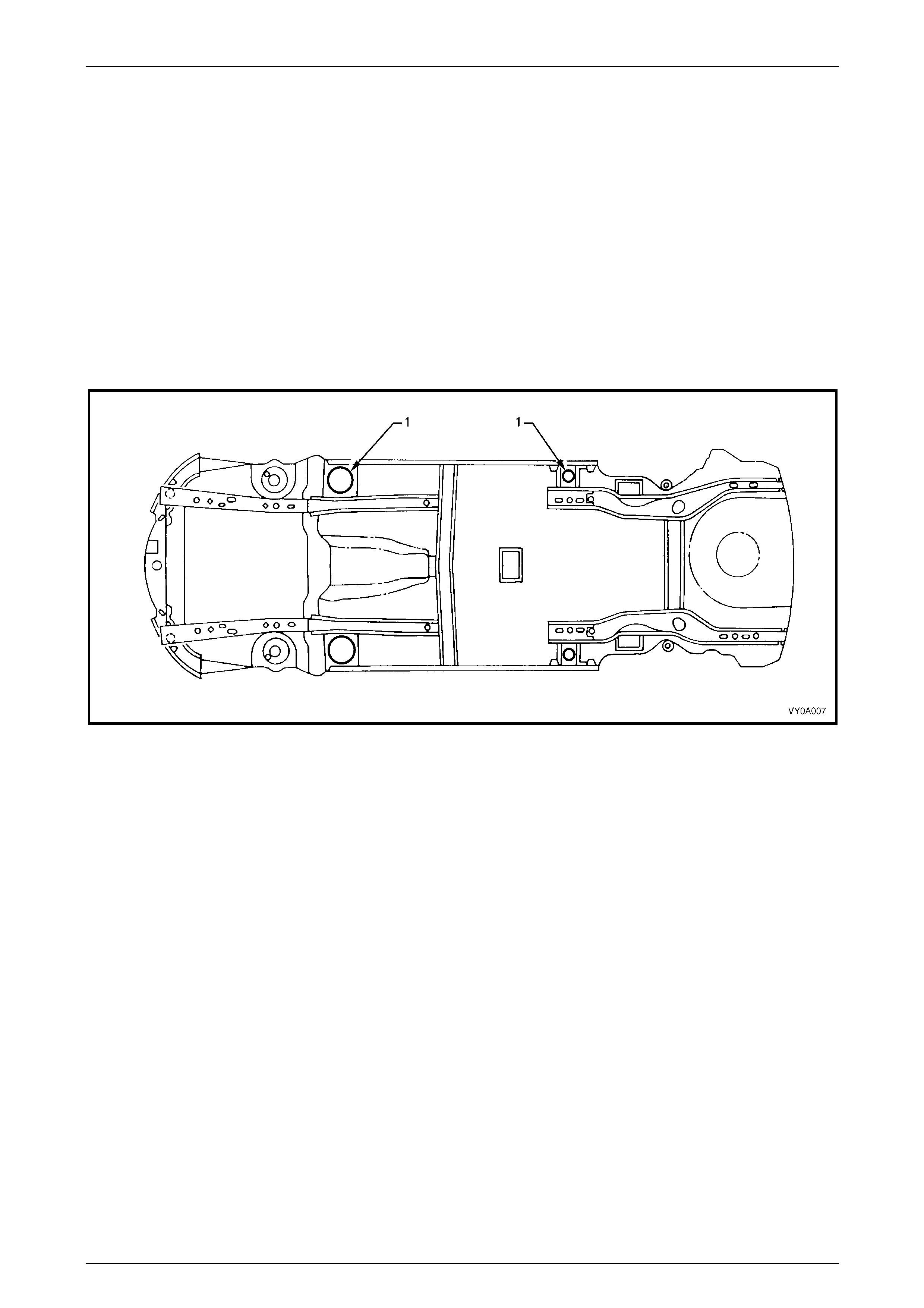
NOTE
• When using a trolley jack to raise the vehicle,
it is important that the jack be positioned
under the suspension crossmember or hoist
pad locations (1). Refer to Figure 2 – 2.
• Do not jack under the suspension control
arms. The vehicle should always be
supported by jack stands at the hoist pad
locations when raised.
Sedan, Wagon, Utility, Coupe and AWD Wagon
Figure 2 – 2
2 Precautions Page 2-23
Page 2-23
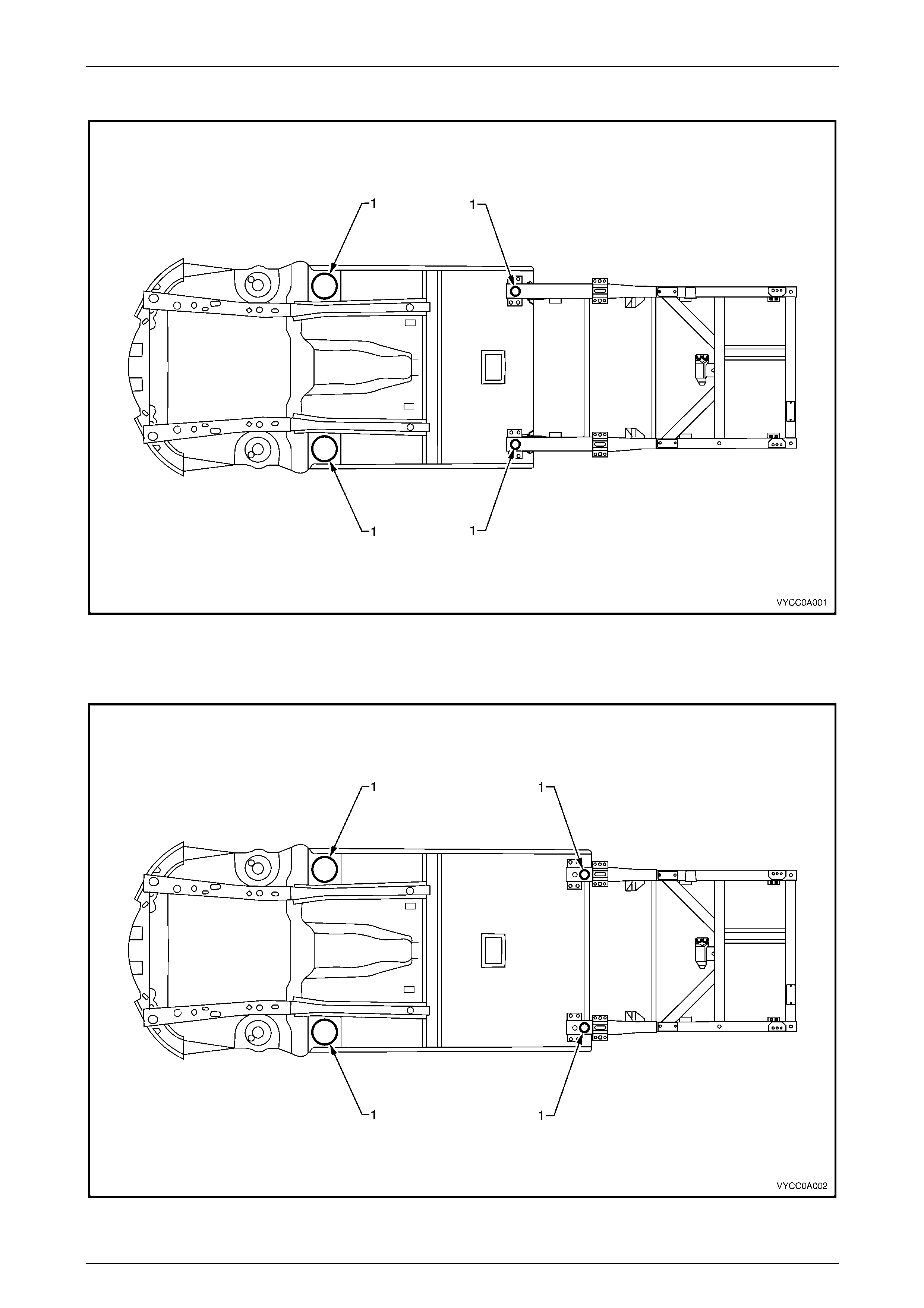
Regular Cab
Figure 2 – 3
Crew Cab
Figure 2 – 4

2 Precautions Page 2-24
Page 2-24
7 Towing Precautions
The correct lifting or towing equipment is necessary when lifting or towing the vehicle to prevent damage during an y
towing operation.
The preferred method for towing the vehic le is on a vehicle transporter (tilt- t ray, etc.) or with a vehicle and equipment that
has the ability to raise all wheels off the ground. If these methods are not available, then the following can be performed
providing the following preca utions are taken.
NOTE
Towing the vehicle is th e sole responsibilit y o f the
individual tow truck operator and is at his/her
discretion as to the appropriate method of towing
a vehicle in each instance. State and Local laws
must be obeyed at all times.
7.1 Towing On Four Wheels
If unavoidable, the vehicle may be towed on all four wheels taking note of the following precautions:
• Switch the ignition key to the ACC position to free the steering lock.
• Ensure that the transmission (Manual or Automatic) is in Neutral position.
• Remove the propeller shaft if the transmission is damaged.
If it is not possible to following these precautions, then the vehicle must be transported on a special vehicle transporter.
NOTE
• Vehicles fitted with automatic transmission
must not be towed at a speed over 55 km/h
unless the propeller shaft is removed.
• Do not attach towing equipment to the
bumper bars or brackets.
• Only one person (to steer the vehicle) is
permitted in the towed vehicle; passengers
are not allowed.

2 Precautions Page 2-25
Page 2-25
7.2 Towing On Two Wheels
RWD vehicles fitted with automatic
transmission must not be towed on the driven
wheels at a speed over 55 km/h unless the
appropriate propeller shaft is removed. For
AWD vehicles the appropriate propeller shaft
for the wheels that remain on the ground
must be removed regardless of speed or
distance. Failure to do so can result in
transmission or transfer case damage.
If unavoidable, the vehicle may be towed with two wheels off the ground under the following conditions:
• If towing the vehicle from the rear, do not use the steering lock to lock the front wheels in the straight ahead
position. The steering lock must be free, as the steering lock mechanism a nd ignition switch may be damage d if
used to prevent the steering from moving while towing. Use other appropriate means of securing the steering in the
straight ahead position.
• Take care not to foul the brake pip es. Do not use suspension components as lifting points.
• Ensure the transmission (Manual or Automatic) is in the Neutral position.
If it is not possible to following these precautions, then the vehicle must be transported on a special vehicle transporter.
2 Precautions Page 2-26
Page 2-26
8 Plastic Components
Plastic components are used throughout the vehicl e. The following table is included to ass ist with the identification and
plastic composition of common compone nts. Refer to 8.9 Plastic Types for a description and handling notes for each
different plastic composition. The plastic components used can also vary from vehicle to vehicle.
NOTE
Most components are also identified with the
material code in an incons picuous location.
8.1 Common to all Vehicles
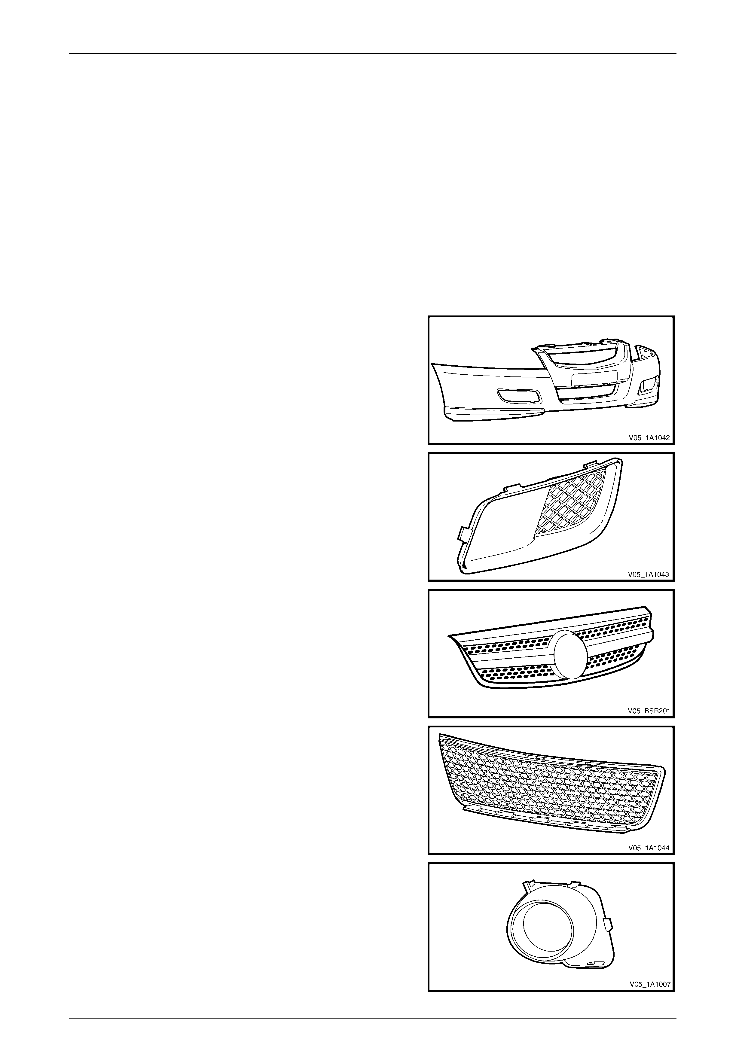
Exterior
Front Bumper Fascia
Material: PP
Front Bumper Access Hole Cover, Level 1
Material: PP
Radiator Grille Assembly
Material: Painted – ABS, Unpainted – ASA
Lower Radiator Grille
Material: PP
Front Fog lamp Bezel Assembly
Material: Inner – ASA, Outer – ABS
2 Precautions Page 2-27
Page 2-27
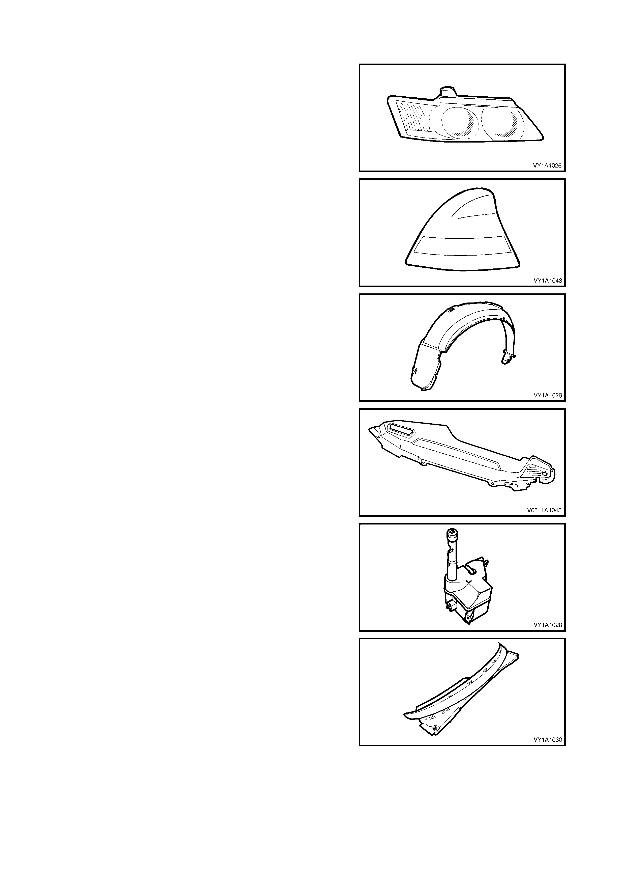
Headlamp Assembly
Material: Lens – PC, Housing – PP/T30
Tail lamp Assembly
Material: Lens – PMMA, Housing – ABS
Wheelhouse Li ner
Material: PP
Upper Radiator Air Baffle
Material: PP
Radiator Overflow Reservoir Assembly
Material: PP
Plenum Cover Assembly
Material: PP
2 Precautions Page 2-28
Page 2-28
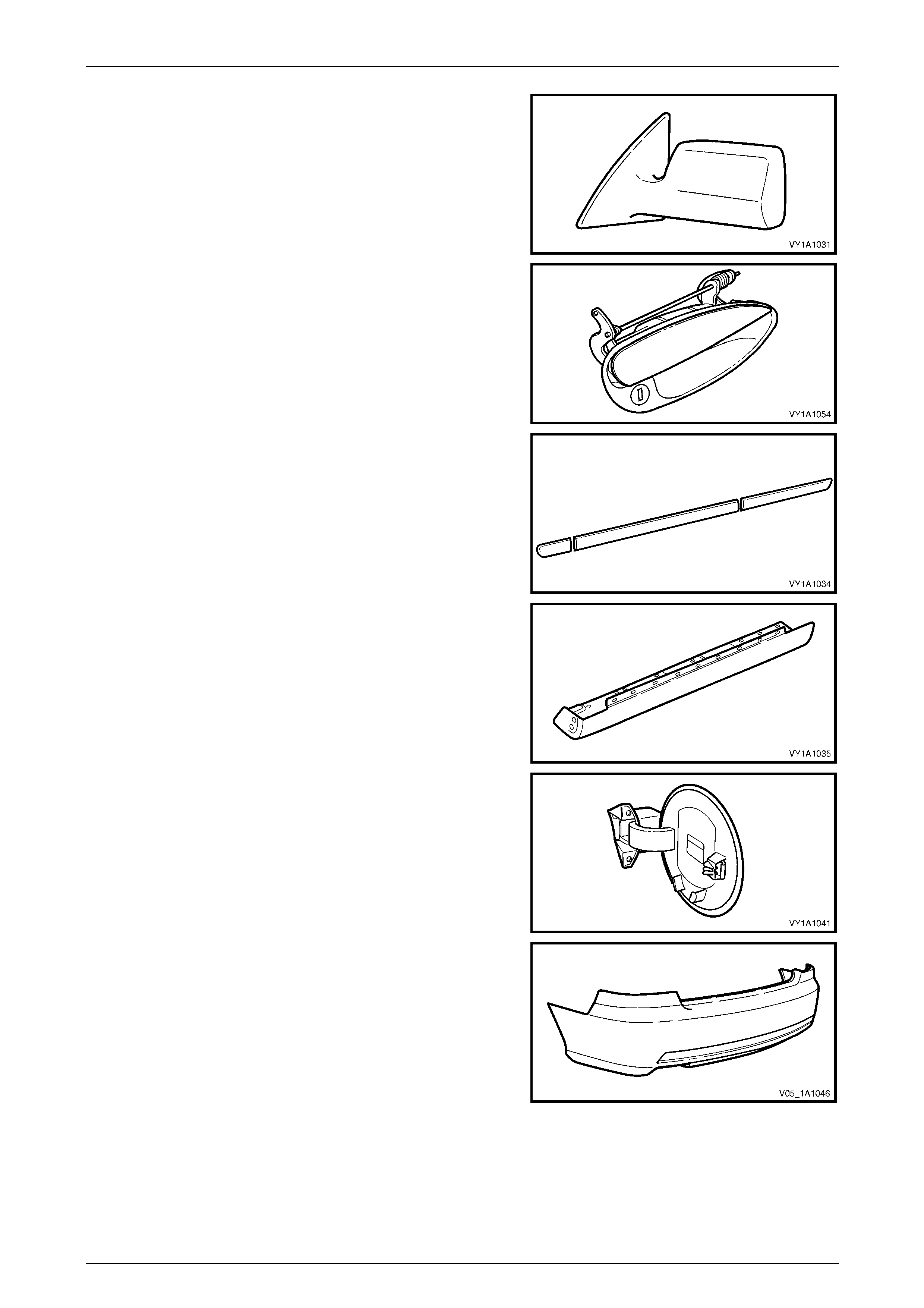
Outside Rear View Mirror Housing
Material: Painted – ABS, Unpainted - ASA / PC
Door Handle Assembly
Material: PA 66
Body Side Moulding
Material: ASA
Rocker Panel Moulding Assembly
Material: PP
Fuel Filler Door
Material: PPE / PA
Rear Bumper Fascia
Material: PP
2 Precautions Page 2-29
Page 2-29
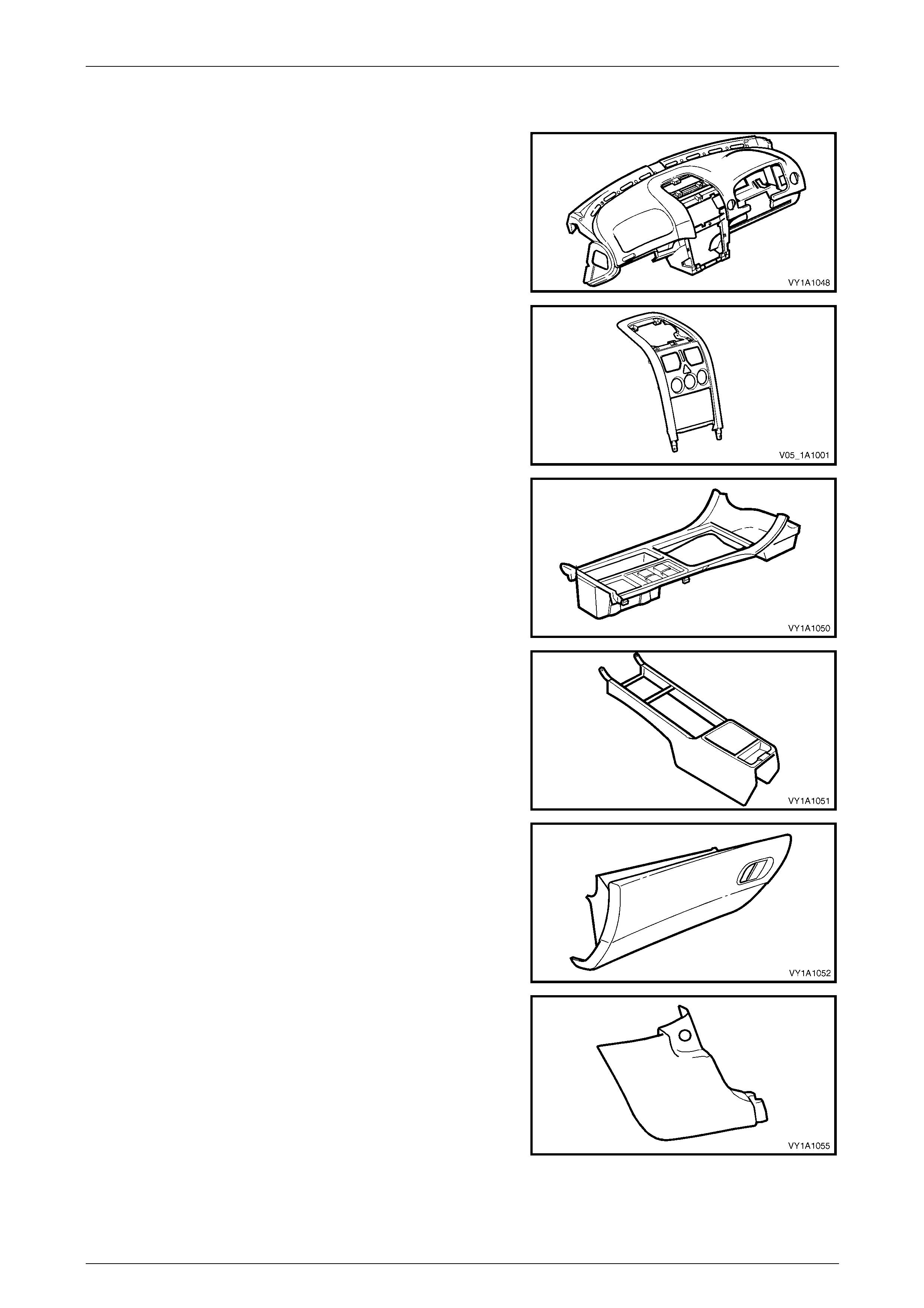
Interior
Instrument Panel Pad Assembly
Material: Carrier – ABS, Pad Substrate – PP, Foam – PVC, Skin - ABS
Instrument Panel Centre Trim Assembly
Material: PC/ABS
Floor Console Cover Assembly
Material: PC/ABS
Front Floor Console
Material: PP
Instrument Panel Compartment
Material: PP
Hinge Pillar Trim
Material: PP
2 Precautions Page 2-30
Page 2-30
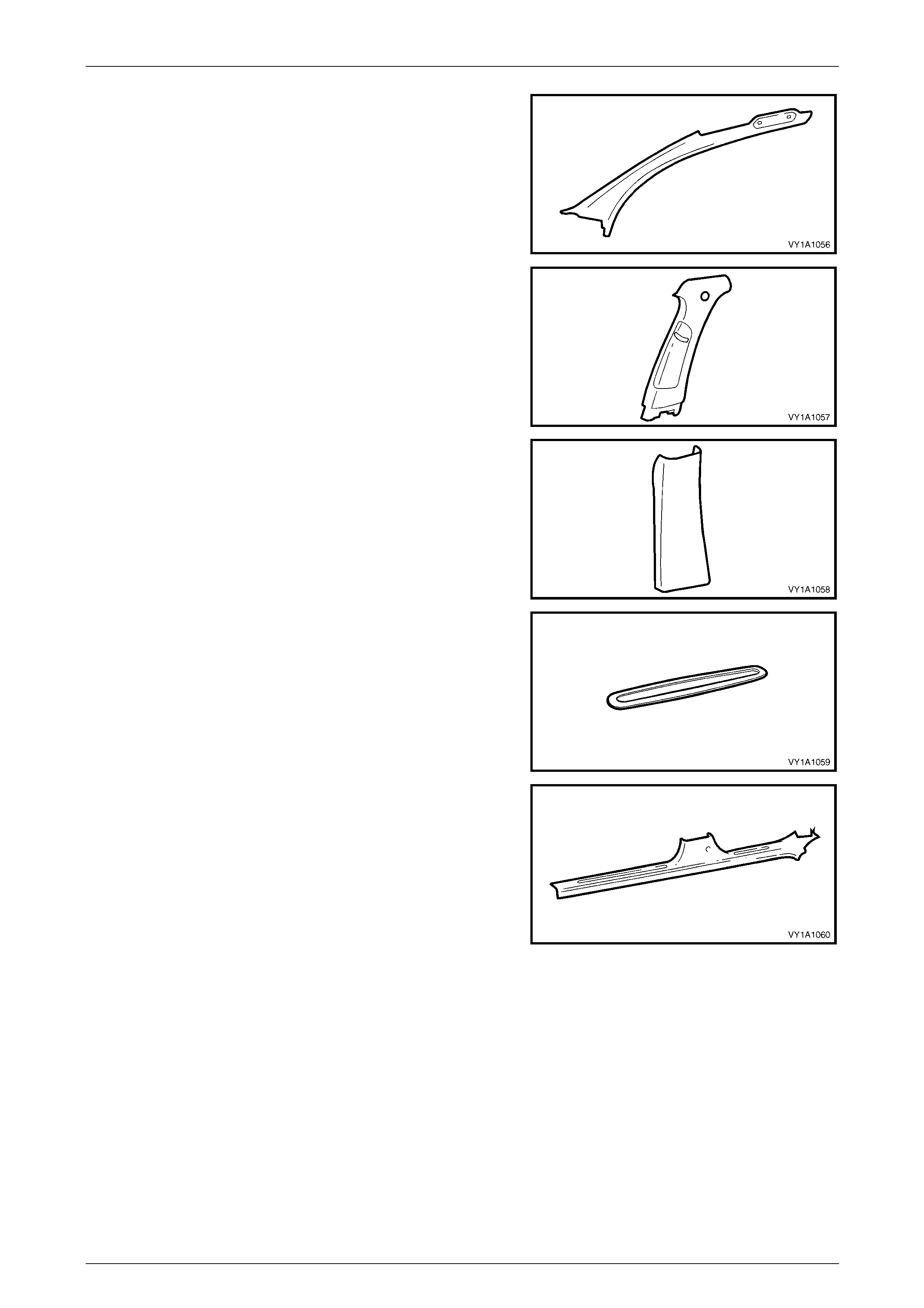
Windscreen Side Garnish
Material: PP
Centre Pillar Upper Trim
Material: PP
Centre Pillar Lower Trim
Material: PP
Side Sill Trim Plate
Material: PP
Side Sill Trim
Material: PP
2 Precautions Page 2-31
Page 2-31
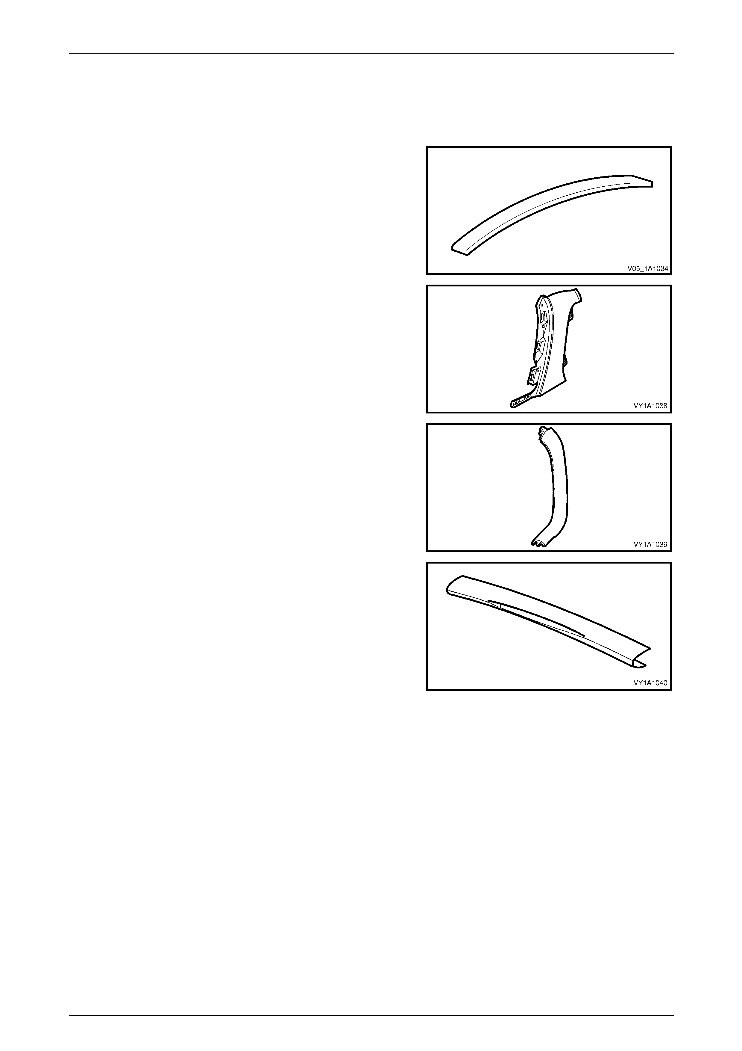
8.2 Sedan Unique
Exterior
Roof Panel Joint Moulding Assembly
Material: PVC
Quarter Panel Belt Moulding
Material: PPE/PA-M20
Rear Spoiler Assembly
Material: ABS
Rear Compartment Lid Appli qué Assembly
Material: ABS
Interior
Body Lock Pillar Garnish
Material: PP
Rear End Trim Panel
Material: PP
2 Precautions Page 2-32
Page 2-32
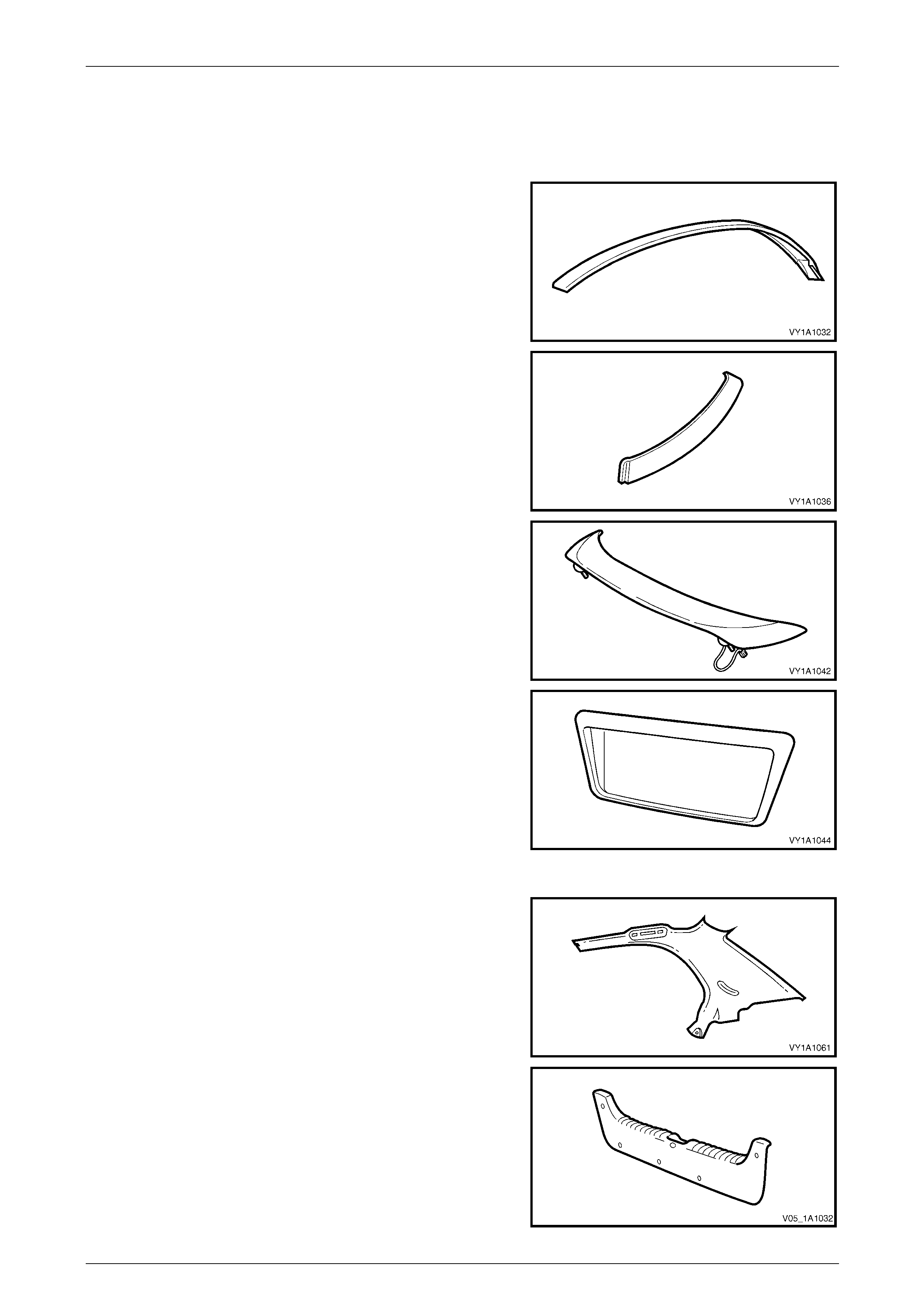
8.3 Wagon Unique
Exterior
Roof Panel Joint Moulding Assembly
Material: PVC
Roof Panel Joint Finish Moulding
Material: PP M20
Liftgate Air Deflector Assembly
Material: PC/ABS
Liftgate Appliqué Assembly
Material: ABS
Interior
Body Lock Pillar Garnish
Material: PP
Body Lock Pillar Lower Trim
Material: PP
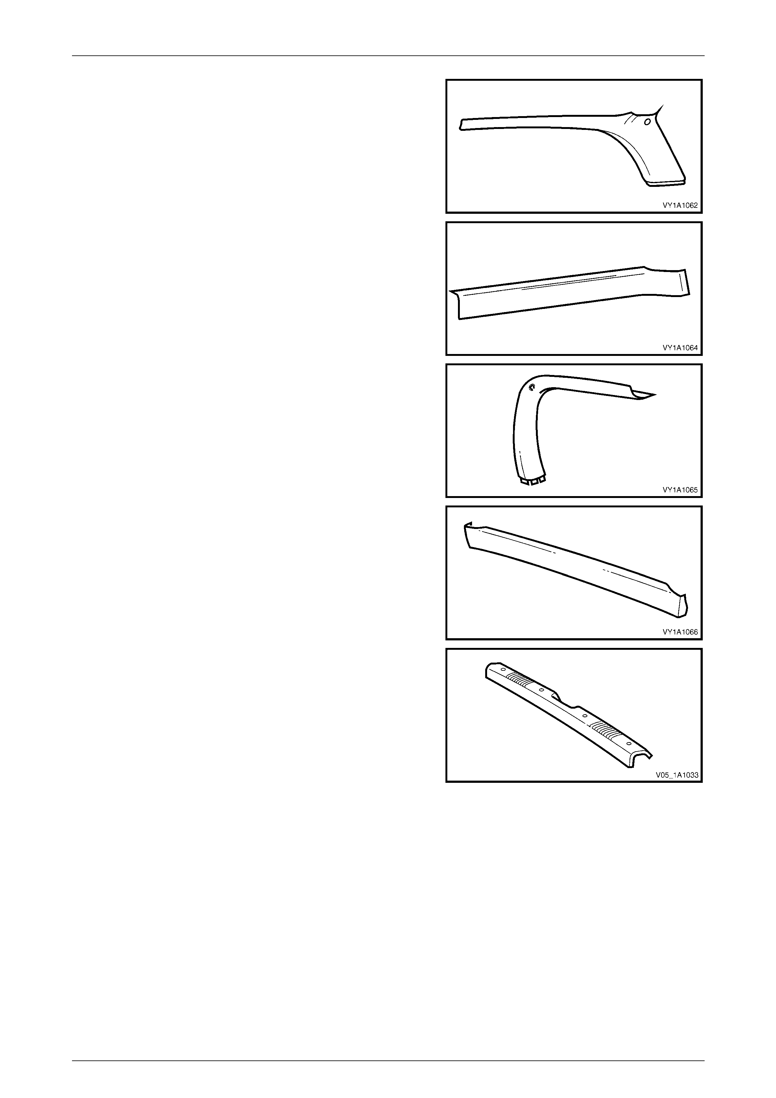
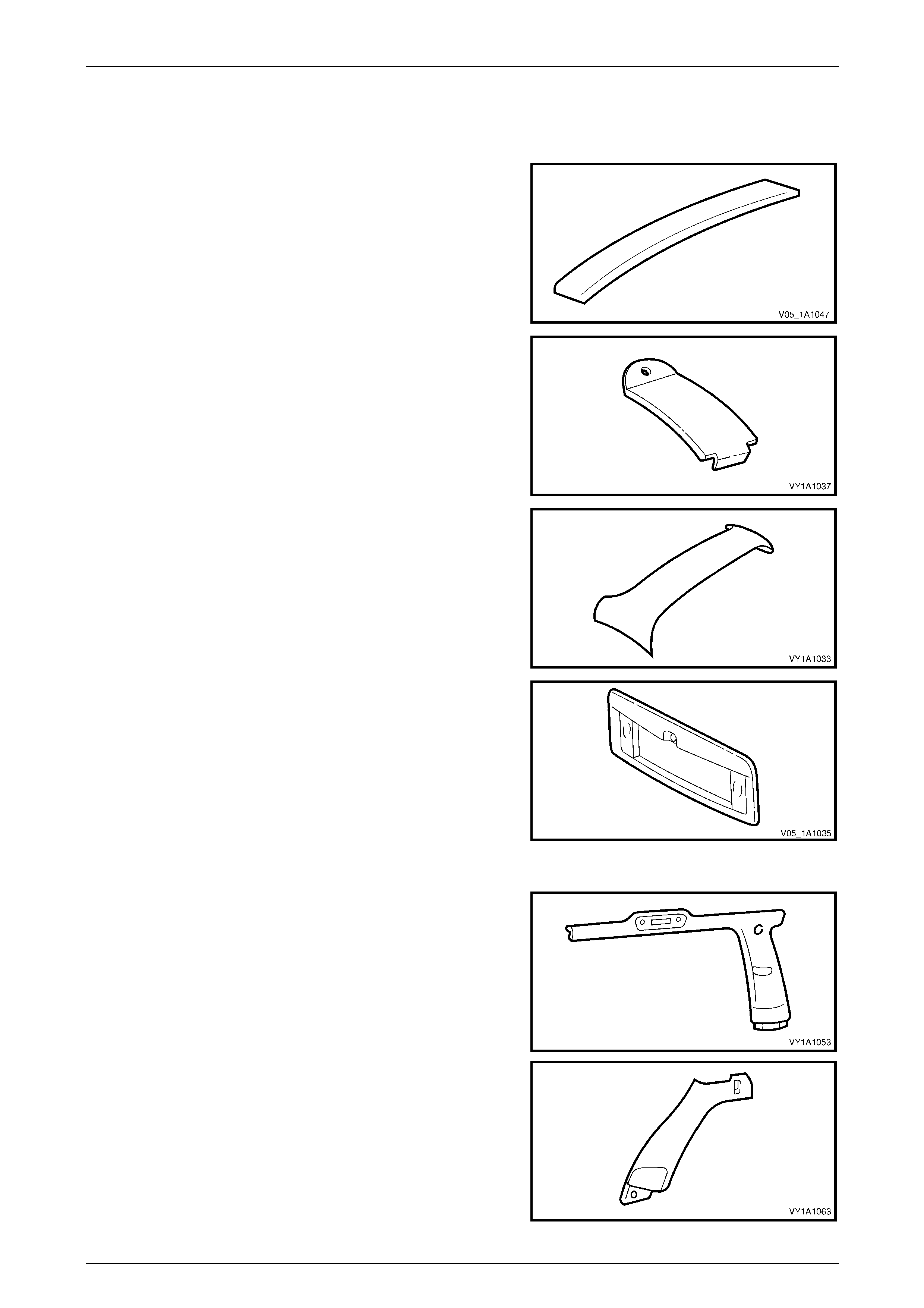
2 Precautions Page 2-33
Page 2-33
Body Lock Corner Garnish
Material: PP
Quarter Inner Trim Upper
Material: PP
Liftgate Window Upper Garnish
Material: PP
Liftgate Window Lower Garnish
Material: PP
Rear End Trim Panel
Material: PP
2 Precautions Page 2-34
Page 2-34
8.4 Utility Unique
Exterior
Roof Panel Joint Moulding Assembly
Material: PP
Rear Quarter Window Mouldi ng
Material: ABS / PC-M6
Rear Window Side Moulding Assembl y
Material: ABS / PC-M6
Rear Window Upper Moulding Assembl y
Material: ABS / PC-M6
2 Precautions Page 2-35
Page 2-35
8.5 Regular Cab Unique
Exterior
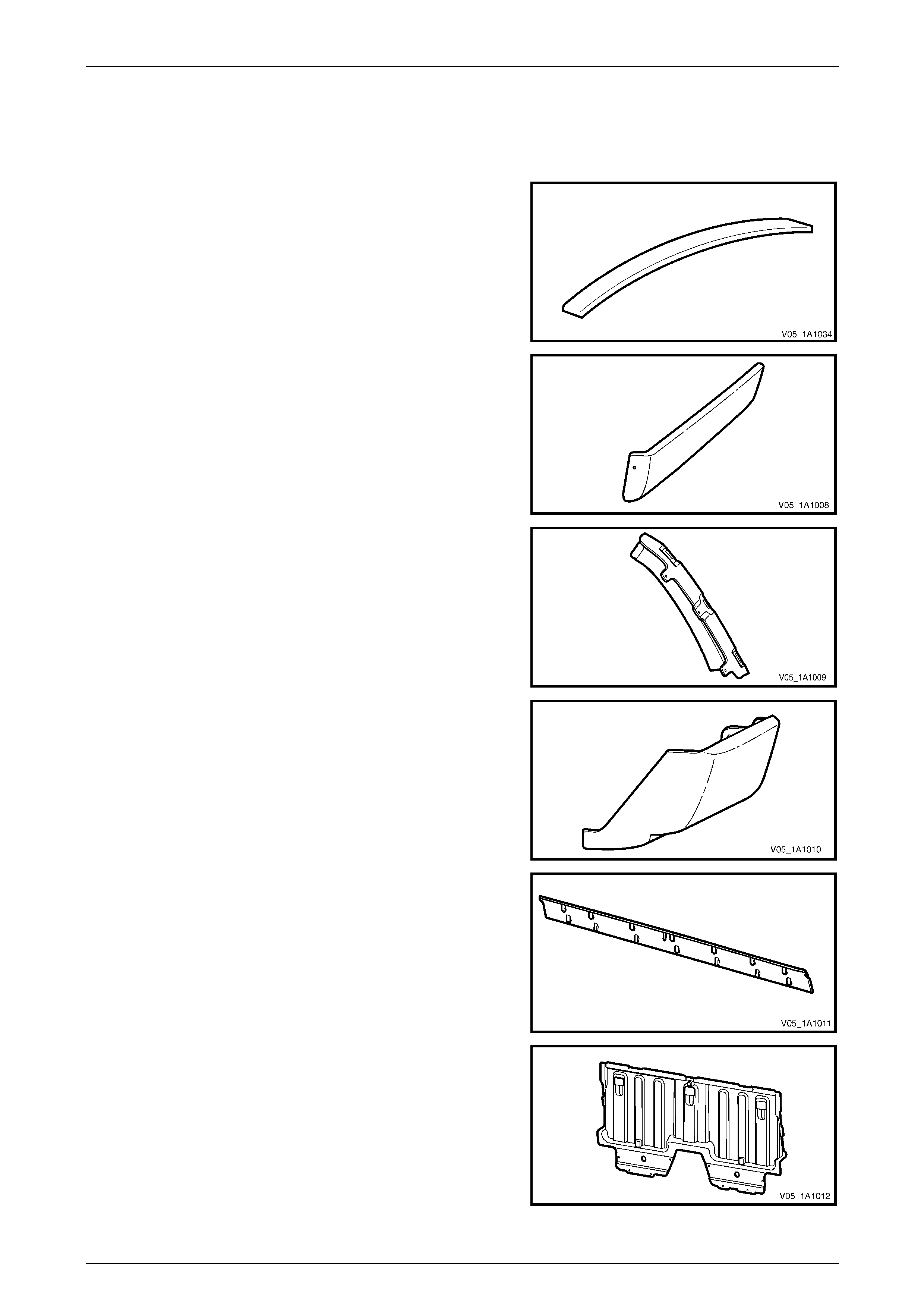
Roof Panel Joint Moulding Assembly
Material: PP
Rocker Panel Rear Moulding Assembly
Material: PP
Body Side Rear Trim Panel Bracket
Material: Nylon 30% F/Glass
Body Side Rear Trim Panel
Material: ABS / PC
Rear Quarter Window Side Moulding Assembly
Material: ABS / PC- M6
Rear Quarter Window Upper Mould ing Assembly
Material: ABS / PC- M6
2 Precautions Page 2-36
Page 2-36
Body Rear Outer Panel Assembly
Material: 10% Fibreglass filled PC
Rear Seatback Body Panel Trim Panel Asse mbly
Material: PP
Body Rear Inner Panel
Material: UP
2 Precautions Page 2-37
Page 2-37
8.6 Crew Cab Unique
Exterior
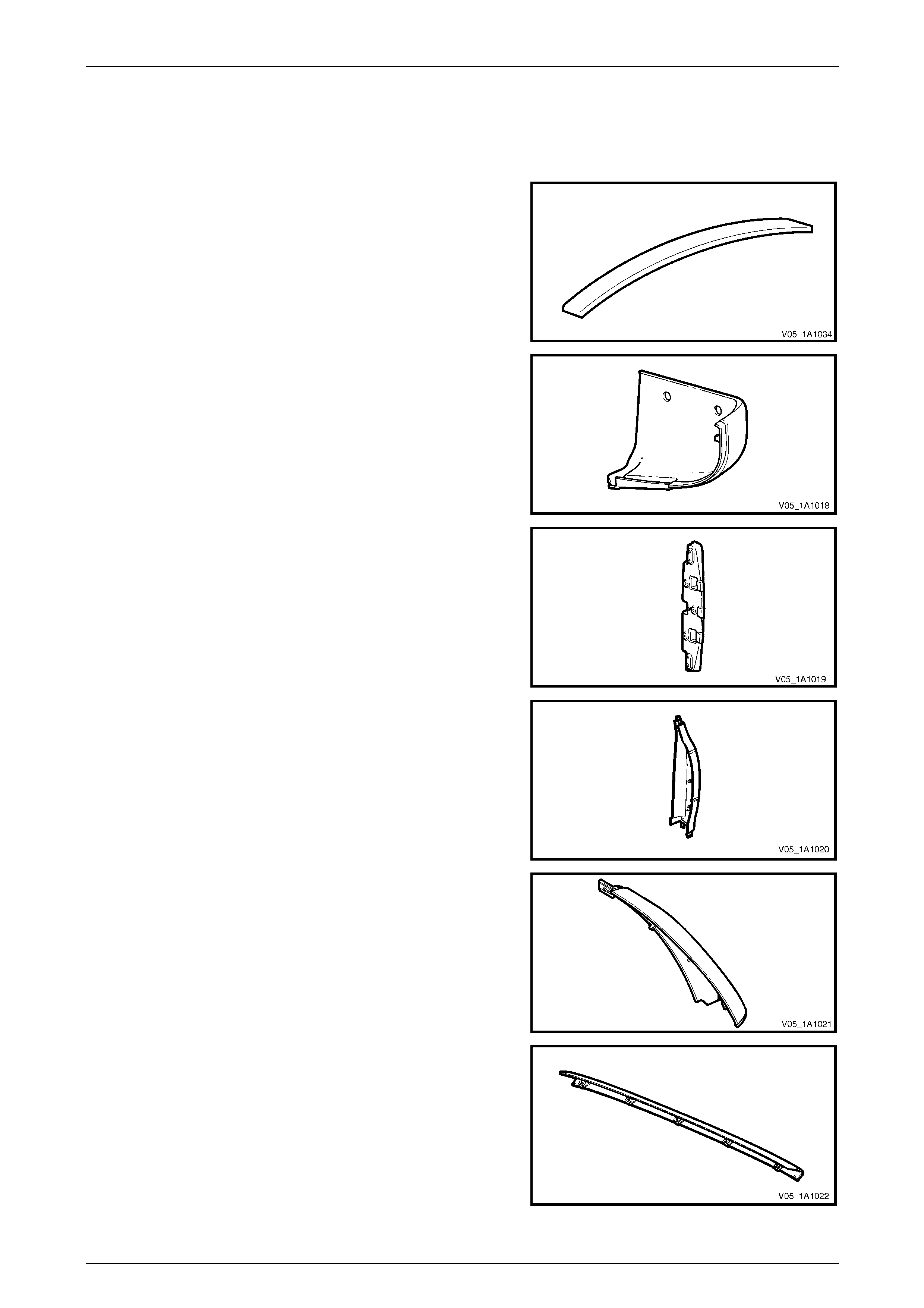
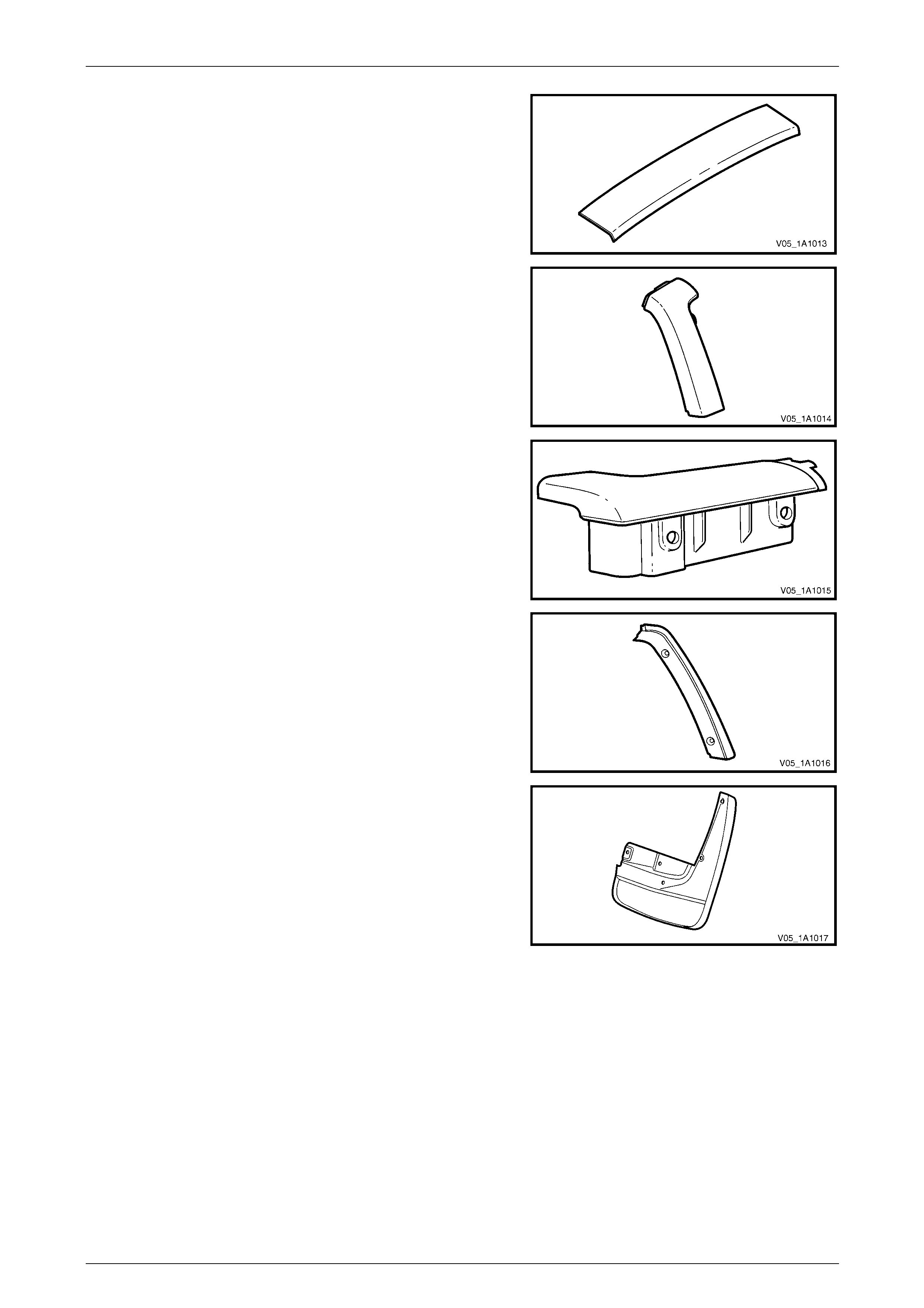
Roof Panel Joint Moulding Assembly
Material: PVC
Rear Body Rear Rocker Moulding
Material: Mineral Filled PP
Body Lock Pillar Trim Retainer Moul ding
Material: Mineral Filled PP
Rear Body Front Rocker Moulding
Material: PP
Rear Window Lower Finisher
Material: ABS / PC
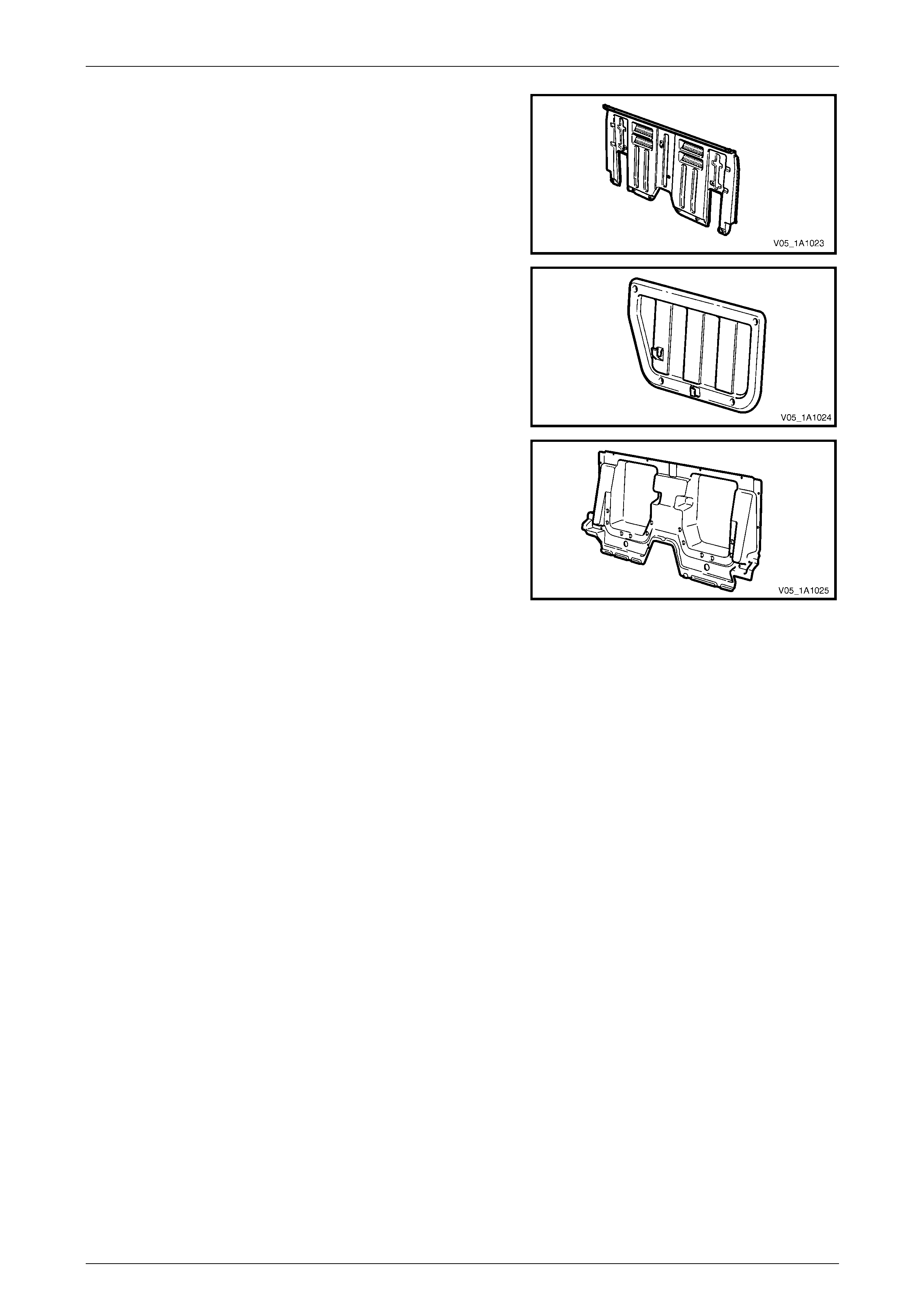
Inner Rear Body Panel
Material:
10% GF Recycled PP
2 Precautions Page 2-38
Page 2-38
Rear Header Trim Assembly
Material: ABS / PC
Body Lock Pillar Trim
Material: ABS / PC
Rear Body Front Rail Cover
Material: Mineral Filled PP
Body Lock Pillar Door Finisher
Material: ABS / PC
Rear Mudflap
Material: PP
2 Precautions Page 2-39
Page 2-39
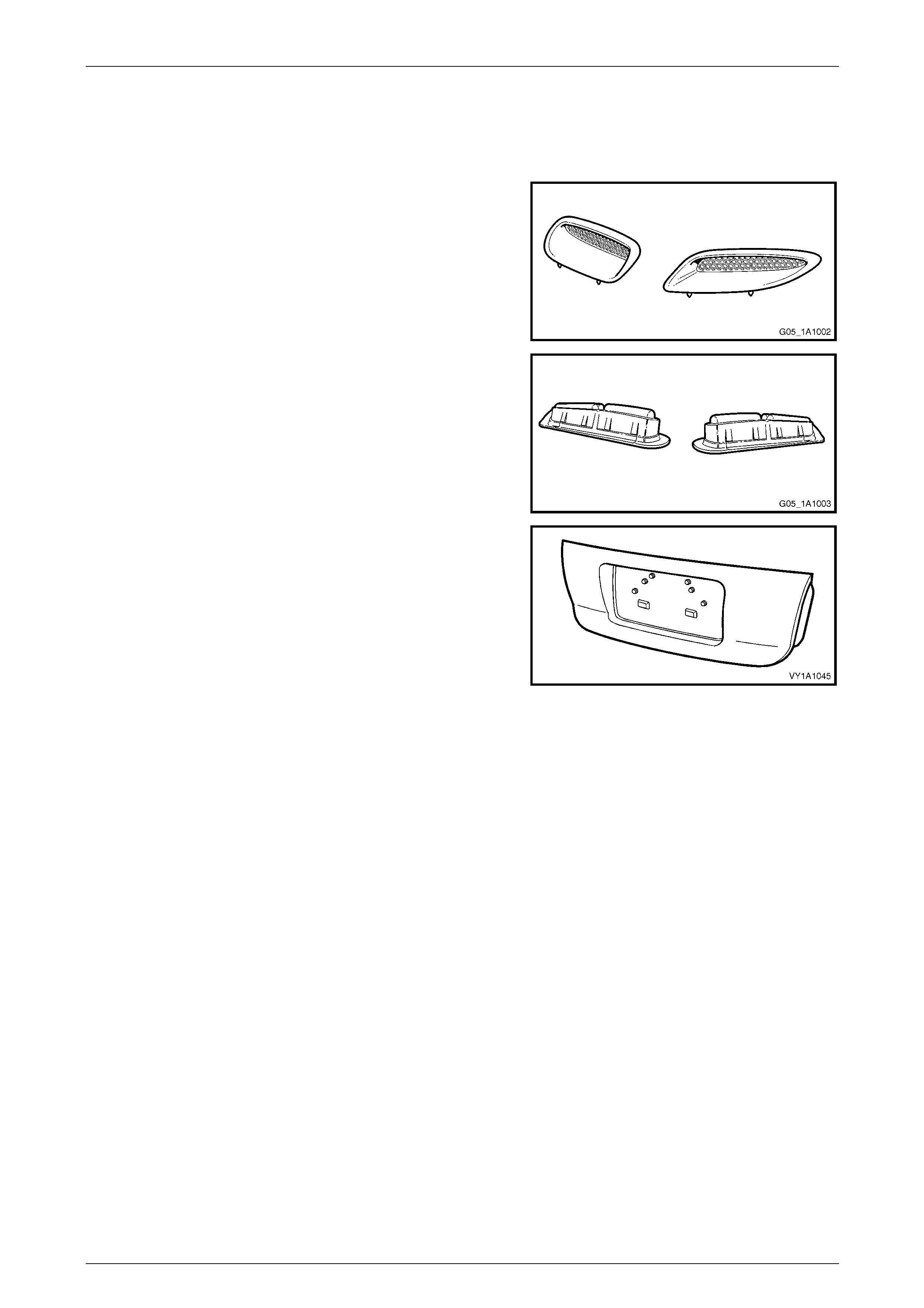
8.7 Coupe Unique
Exterior
Hood Scoop Assembly
Material: PC/ABS
Hood Scoop Air Duct
Material: Rubber modified PP
Rear Compartment Lid Appli qué Assembly
Material: ABS
2 Precautions Page 2-40
Page 2-40
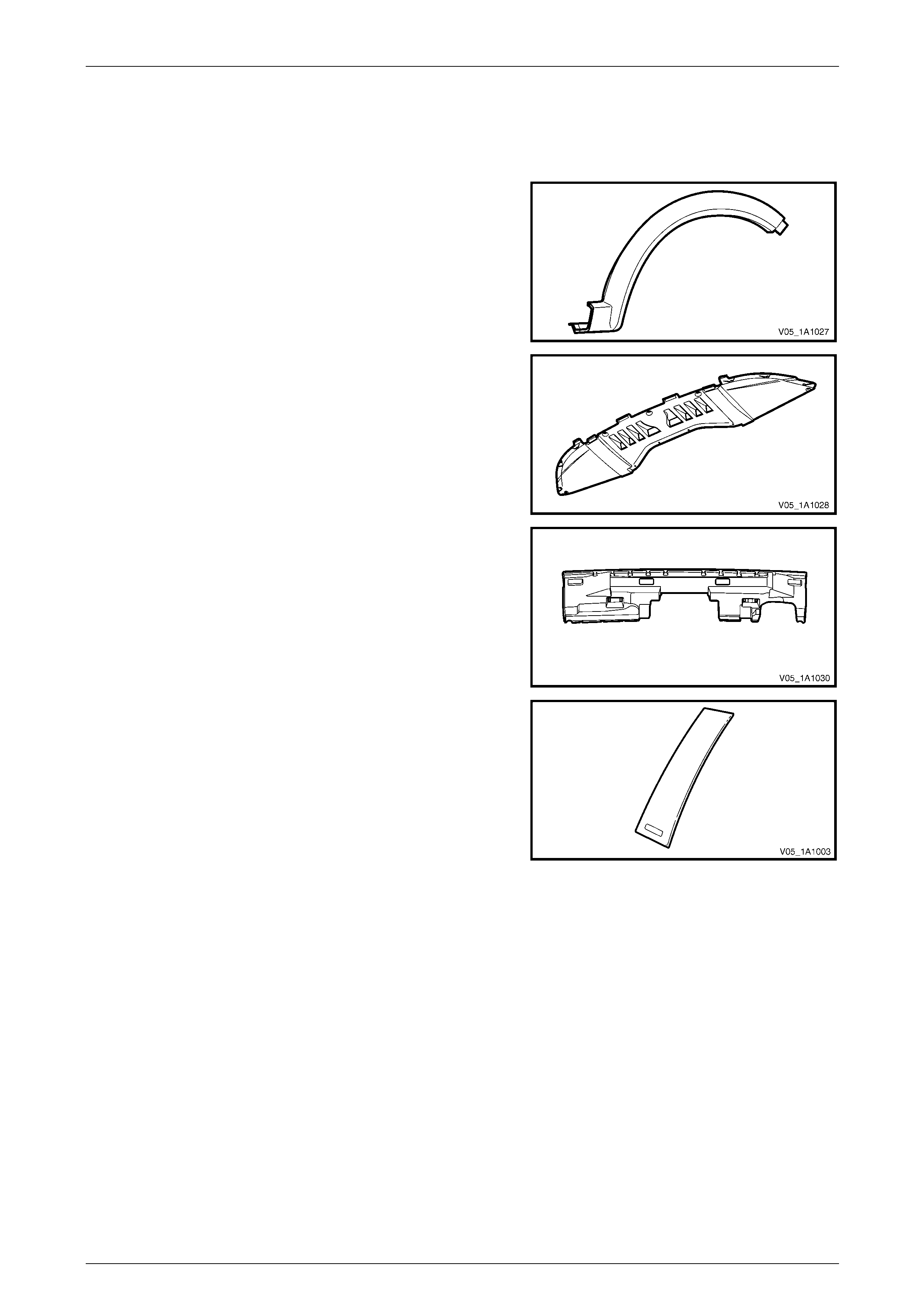
8.8 AWD Wagon Unique
Exterior
Front Wheelhouse Openin g Flare
Rear Wheelhouse Opening Flare
Material: PP
Front Bumper Fascia Undertray
Material: PP
Rear Bumper Fascia Filler
Material: PP Foam
Rear Quarter Window Appliqué
Material: ABS / PC

2 Precautions Page 2-41
Page 2-41
8.9 Plastic Types
The repair procedure for plastic body parts must conform with the type of plastic material.
Precautions to be taken with plastic parts are detailed in the following chart:
Code Material Name Heat Resisting
Temp* °C Resistance to
Alcohol or Gasoline NOTES
ABS Acrylonitrile
Butadiene Styrene
Resin
80 Alcohol is harmless if applied only
for short time in small amounts (i.e.
quick wiping to remove grease).
Avoid gasoline and organic
or aromatic solvents.
ASA Acrylate Styrene
Acrylonitrile 80 Alcohol is harmless if applied only
for short time in small amounts (i.e.
quick wiping to remove grease).
Avoid gasoline and organic
or aromatic solvents.
PC Polycarbonate 120 Alcohol is harmless. Avoid gasoline, brake fluid,
wax, wax removers and
organic solvents.
PMMA Polymethyl
Methacrylate 80 Alcohol is harmless if applied only
for short time in small amounts. Avoid dipping or immersing
in alcohol, gasoline,
solvents, etc.
PE Polyethylene 80 Alcohol and gasoline are harmless. Most solvents are harmless.
PP /
PP67 Polypropylene 80 Alcohol and gasoline are harmless. Most solvents are harmless.
PPE Polyphenylene
Ether 100 Alcohol and gasoline are h armless if
applied only for a short time in small
amounts (i.e. quick wiping to remove
grease).
Avoid dipping or immersing
in alcohol, gasoline,
solvents, etc.
PU Polyurethane
Foam 100 Alcohol and gasoline are h armless if
applied only for a short time in small
amounts (i.e. quick wiping to remove
grease).
Avoid dipping or immersing
in alcohol, gasoline,
solvents, etc.
PVC Polyvinyl Chloride 80 Alcohol and gasoline are h armless if
applied only for short time in small
amounts. (i.e. quick wiping to
remove grease).
Avoid dipping or immersing
in alcohol, gasoline,
solvents, etc.
TPO Thermoplastic
Olefin 80 Alcohol is harmless.
Gasoline is harmless if applied only
for short time in small amounts.
Most solvents are harmless
but avoid dipping or
immersing in alcohol,
gasoline, solvents, etc.
PPE/
PA-M20 Modified
Polypropylene
Ether and
Polyamide Alloy
190 Alcohol and gasoline are h armless if
applied only for a short time in small
amounts (i.e. quick wiping to remove
grease).
Avoid dipping or immersing
in alcohol, gasoline,
solvents, etc.

2 Precautions Page 2-42
Page 2-42
9 Special Steel Precautions
A number of different types of steel are used for the panels and b od y structure of vehicles. These are as follows.
9.1 Pre-Coated Steel
In the steel manufacturing process, a corrosi on protection layer of zinc-nickel alloy, galvaneal or zinc ric h coating, is
applied to one or both of the surfaces. This layer is very thin and can easily be burnt or eroded away under repair
conditions.
Most repairs such as sanding, grinding or welding will remove the protective layer. To maintain the corrosio n protection
of the vehicle after repairs, both sides of the panel should be painted with a zinc rich primer, primer surfacer and topcoat
of refinish paint where possible.
NOTE
If it is not possible to cover the inside surface of
the panel with pai nt, cavit y wax should be used to
prevent premature corrosion. Refer to
Section 3 Body Construction in this Supplement.

2 Precautions Page 2-43
Page 2-43
9.2 Re-phosphorised Steel
Re-phosphorised steels are used in many areas for their high strength properties, but can be repaired and welded in the
same manner as conventional low carbon steels.
2 Precautions Page 2-44
Page 2-44
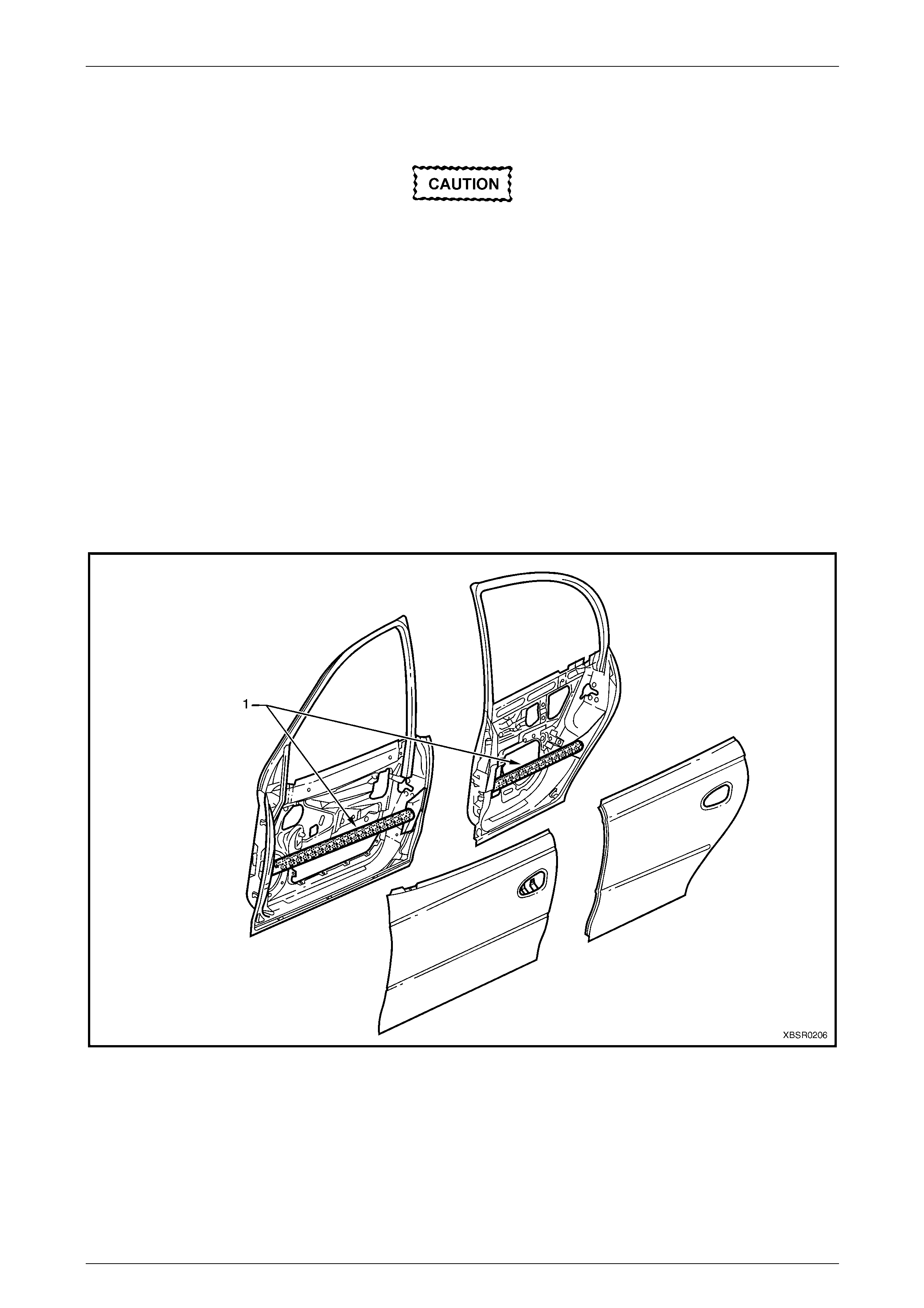
9.3 High Strength Low Alloy Steel
Components manufactured from high
strength low alloy (HSLA) steel must not be
heated, welded or straightened in any way. If
a door anti-intrusion beam is damaged, the
only acceptable practice is to replace the
complete door assembly.
High strength low alloy (HSLA) steels are used in the primar y structure of the v ehicle because of their high strength
properties. Many are readily repairable and weldable using MIG or Arc welding equipment, however some must not be
heated or repaired at all.
Heat sensitivity and repair ability of the material is dependent on the chemical composition of the specific HSLA grade
and/or level of cold work in the manufacture of the part.
The further application of heat may anneal (soften) the material, while cold repair can fatigue and weaken it, leadin g to
failure.
The door anti-intrusion beams (1) fitted within all doors are critical to driver/passen ger safety in side impact
displacements, refer to Figure 2 – 5.
Figure 2 – 5
2 Precautions Page 2-45
Page 2-45
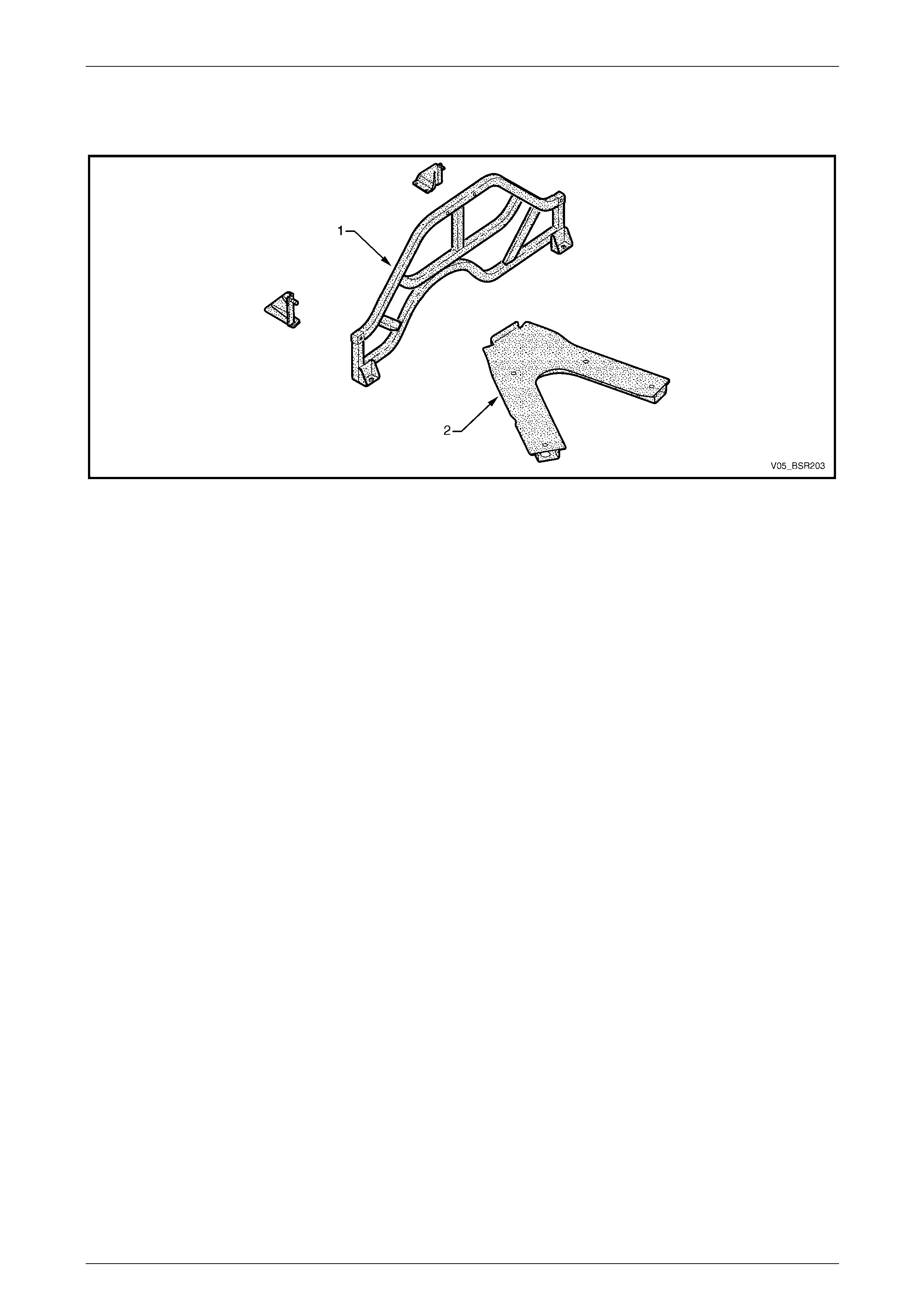
For Coupe only: If the back body opening frame assembly and brackets, or the underbody brace is damaged, the only
acceptable practice is to replace the complete component, refer to Section 1A1 Body in the MY 2005 VZ Service
Information, refer to Figure 2 – 6.
Figure 2 – 6
2 Precautions Page 2-46
Page 2-46
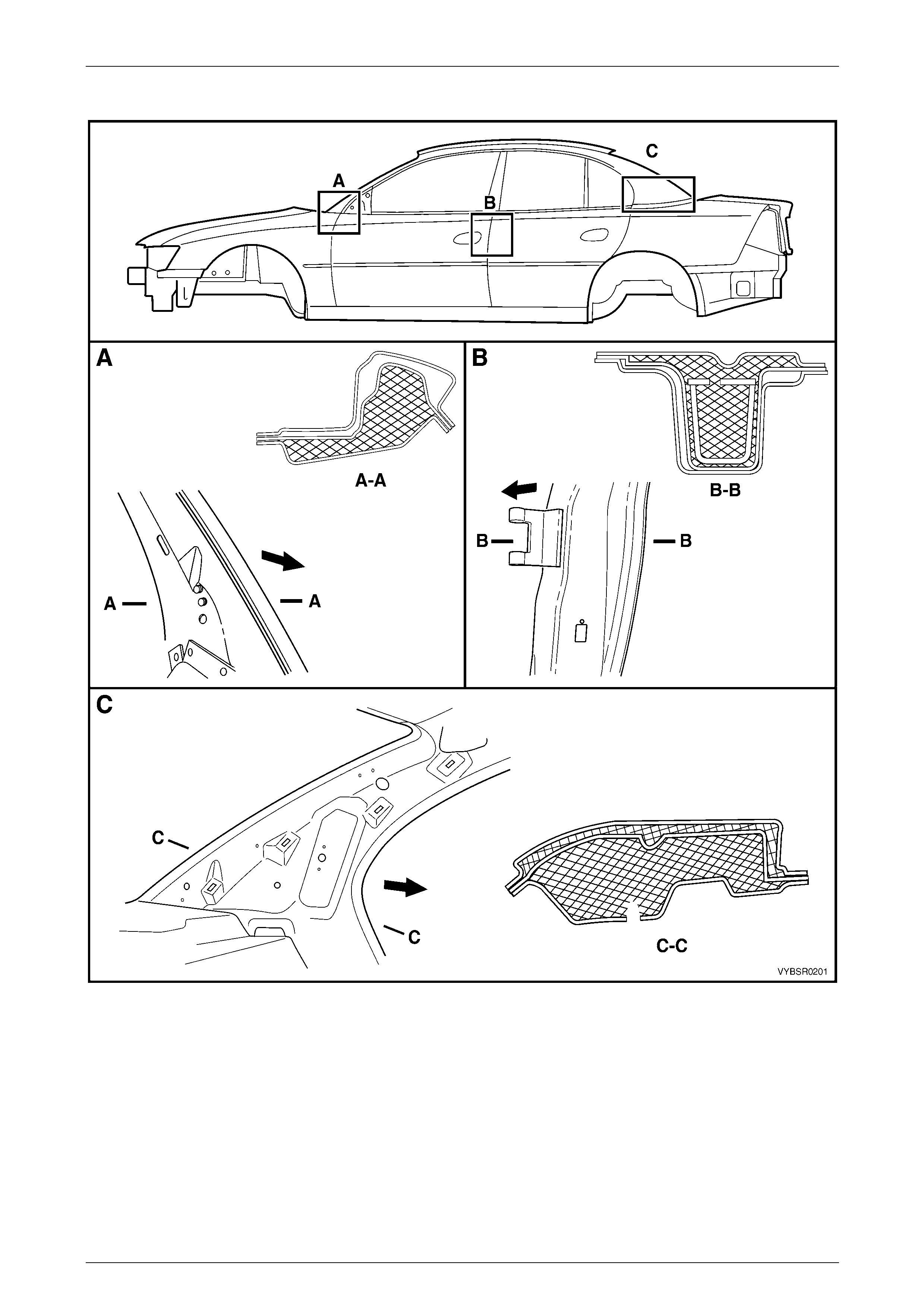
10 Cavity Foam
During manufacture of the vehicle, a cavity foam block is fitted within each pillar cavity as follo ws:
• Sedan – The hinge, centre an d lock pillars, refer to Figure 2 – 7,
• Wagon – The centre pillar only, also refer to Figure 2 – 7,
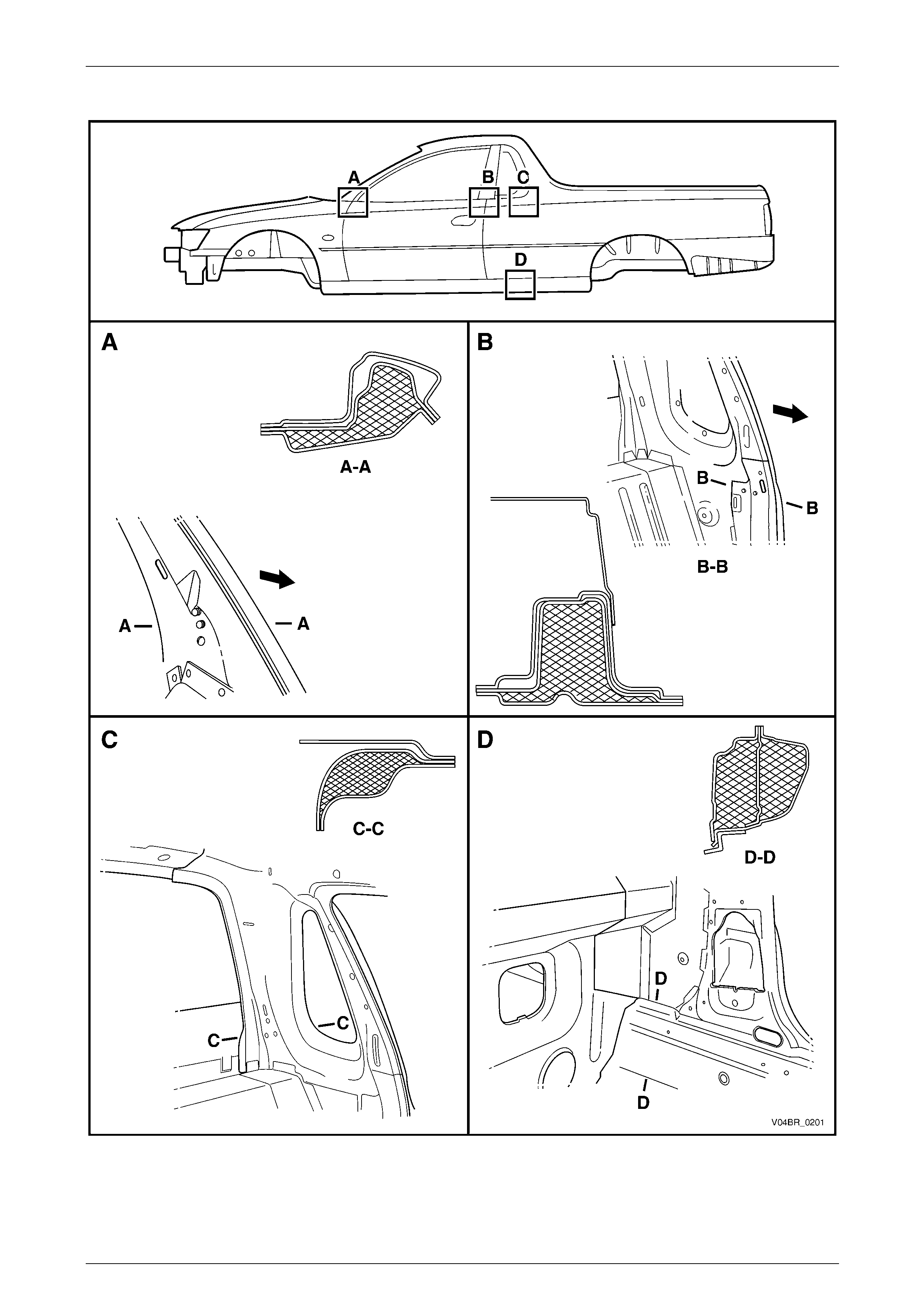
• Utility – The hinge and centre pillars, refer to Figure 2 – 8,
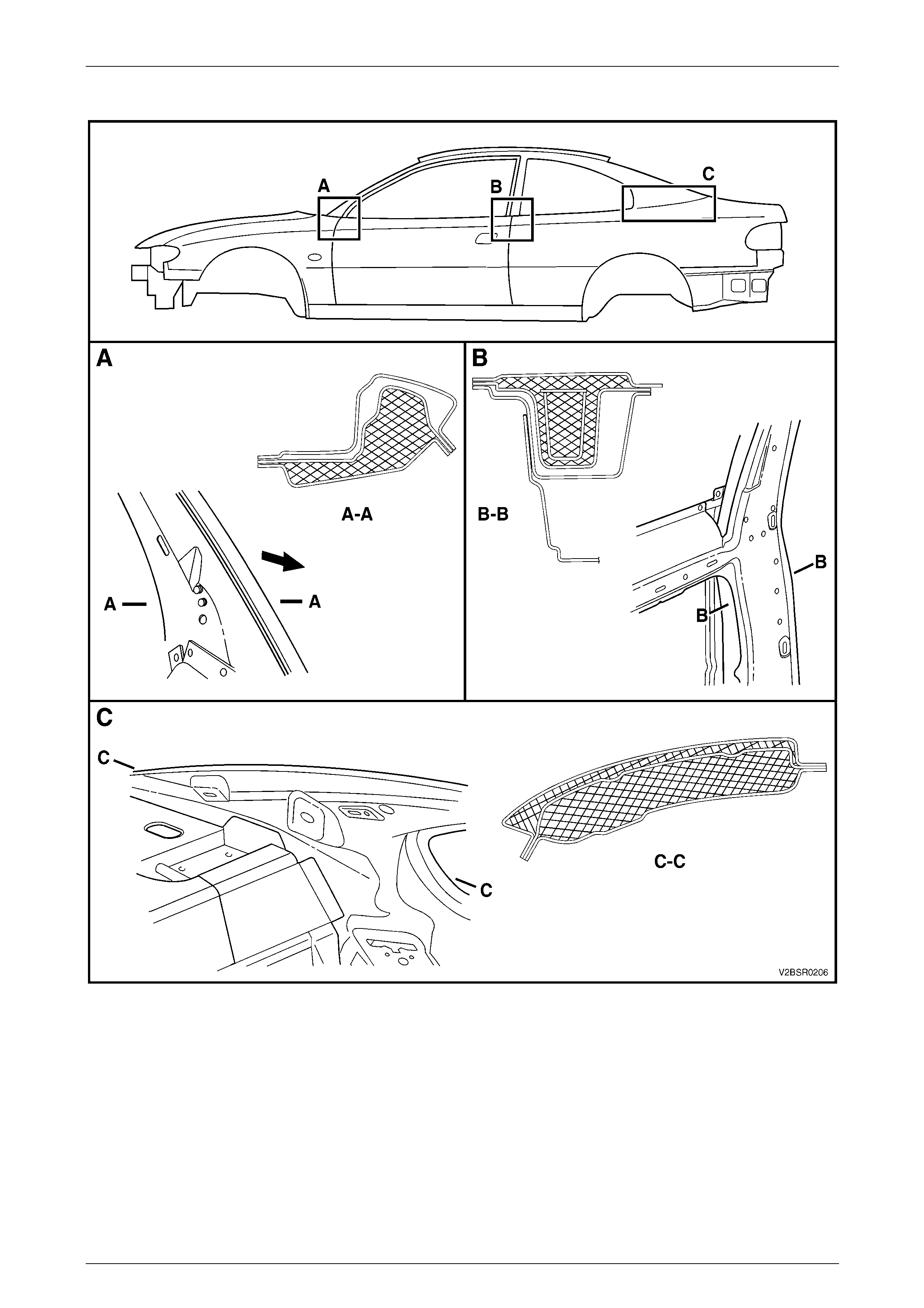
• Coupe – The hinge, centre and lock pillars, refer to Figure 2 – 9.
This foam material, when subjected to a tem perature of approximately 160°C, expands up to 10 times its original size to
seal the cavity and reduce noise transmission.
The use of this material poses no health and
safety risk to a repairer, unless it is heated to
temperatures associated with using
oxy / acetylene equipment or w elding, as to xic
fumes will be emitted which must not be
inhaled.
Prior to welding or heating in the areas shown, the foam must first be removed, usually by cutting it out with a knife.
If a panel or section is replaced, or repair work is performed where the foam is removed, it must be replaced with a
commercially availabl e equivalent, such as those listed, using the following procedure prior to final trim assembly.
NOTE
• The hinge pillar inner panel assembly and
quarter panel inner assembly service parts
are supplied with unc ured fo a m bl anks. T hes e
must not be removed as they act as a support
for the aerosol cavity foam.
• Always read and follow the directions and
safety instructions with the product prior to
usage.
Cavity Foam Equivalents
Brand Product
Sista Multi-purpose Foam
Ramset Expandable Polyurethane Foam
Selleys Space Invader
2 Precautions Page 2-47
Page 2-47
Sedan and Wagon
Figure 2 – 7
Legend
a Hinge Pillar – Sedan Only
b Centre Pillar – Sedan and Wagon c Lock Pillar – Sedan Only
2 Precautions Page 2-48
Page 2-48
Utility
Figure 2 – 8
Legend
a Hinge Pilar
b Centre Pillar c Body Lock Pillar
d Rocker Panel
2 Precautions Page 2-49
Page 2-49
Coupe
Figure 2 – 9
Legend
a Hinge Pilar
b Centre Pillar c Lock Pillar
2 Precautions Page 2-50
Page 2-50
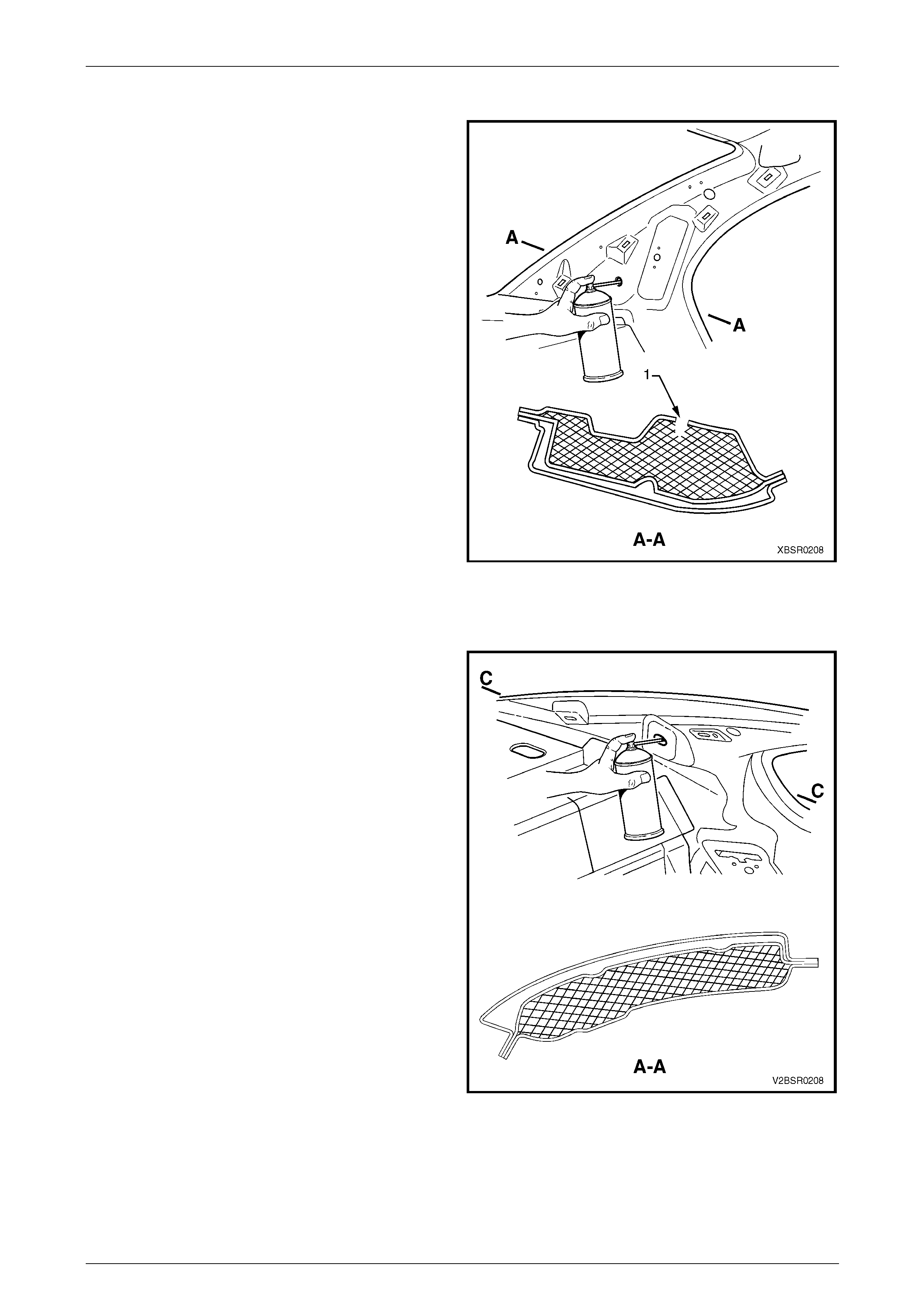
10.1 Cavity Foam – Replace
Hinge Pillar
1 For the hinge pillars, insert the nozzle of the aeroso l
into the trim clip slot (1) above the foam blank.
2 Spray foam into the cavity for several seconds while
drawing the nozzle out. Fill the area to a height of
approximately 50 mm.
3 Once cured, remove a small amount of foam using a
probe to enable the trim clip to seat correctly.
Figure 2 – 10
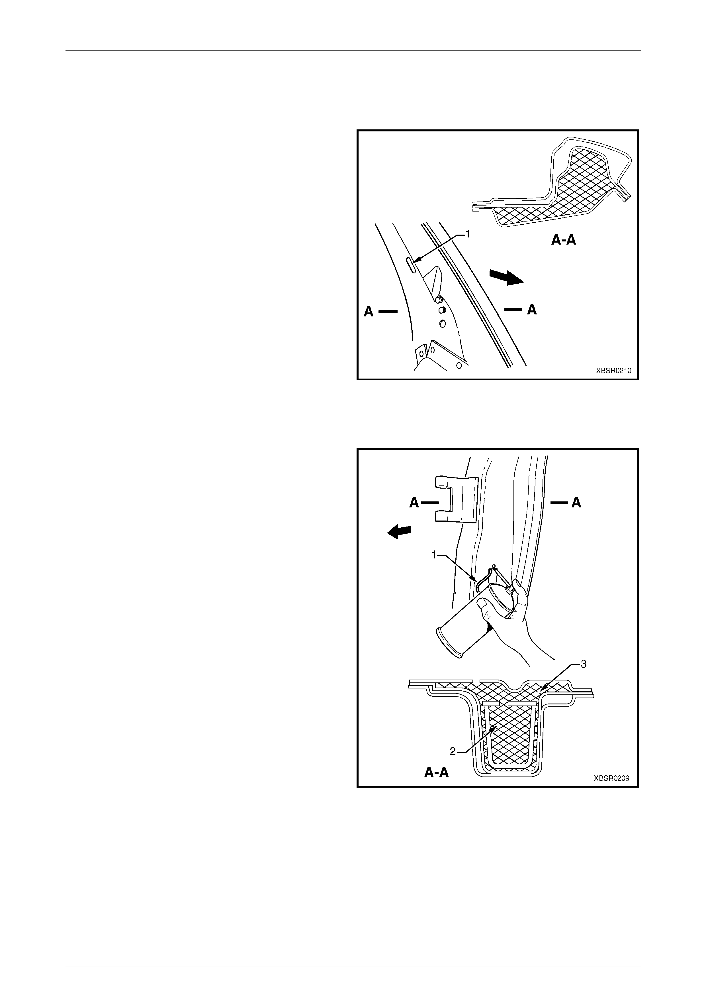
Centre Pillar, Sedan and Wagon
1 For the Sedan and Wagon centre pillars, ensure the
door light switch wire (1) is protruding from the door
light switch opening in the centre pillar.
2 Insert the nozzle of the aerosol as high as possible
within the cavity of the centre pillar inner reinforcement
(2), through the door light switch hole.
NOTE
The nozzle needs to reach a bove the foam block
to avoid the foam falling down the cavity.
3 Spray foam into the cavity for several seconds while
drawing the nozzle out. Fill the area to a height of
approximately 50 mm.
4 Insert the nozzle of the aerosol into the trim clip slot on
the inner side of the pillar, above the foam blank.
Spray foam into the cavity (3) for several seconds
while drawing the nozzle out of the cavity. Fill the area
to a height of approximately 50 mm.
5 Once cured, remove a small amount of foam from the
trim clip slot and door light switch hole us ing a probe.
NOTE
Any residual foam can disrupt operation of the
switch; ensure there is plenty of clearance
around the switch. Figure 2 – 11
2 Precautions Page 2-51
Page 2-51
Centre Pillar, Utility
For the Utility centre pillars, insert the nozzle of the aerosol
into the trim clip slot (1) above the foam blank.
1 Spray foam into the cavity for several seconds while
drawing the nozzle out. Fill the area to a height of
approximately 50 mm.
2 Once cured, remove a small amount of foam using a
probe to enable the trim clip to seat correctly.
Figure 2 – 12
Centre Pillar, Coupe
1 For the Coupe centre pillars it is not possi ble to fill all
cavities. Insert the nozzle of the aerosol into the trim
clip slot in the quarter panel inner assembl y and spray
foam into the cavity for several seconds while drawing
the nozzle out of the cavity. Fill the area to a hei ght of
approximately 50 mm.
2 Once cured, remove any residual foam as required.
Figure 2 – 13
2 Precautions Page 2-52
Page 2-52
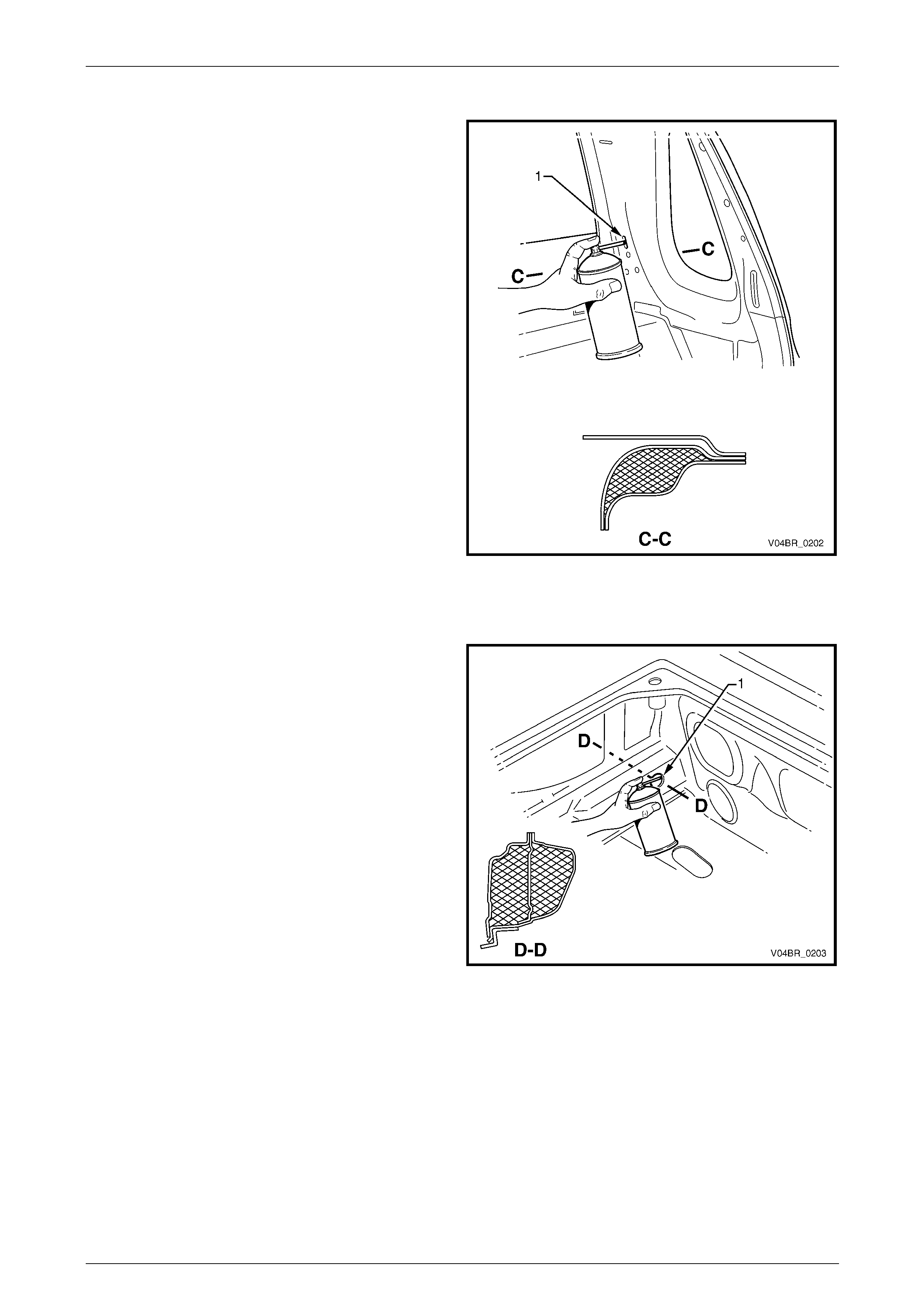
Lock Pillar, Sedan
1 For the Sedan lock pillars, t wo cavities are fill ed
originally. As the outer cavity is inaccessible, it is not a
requirement to fill this cavity with aerosol foam.
2 Insert the nozzle into the trim locating hole (1) as
shown and spray foam into the cavity between the lock
pillar reinforcement and quarter panel inner assembly
for several seconds to a height of approximately
50 mm.
3 Once cured, remove a small amount of foam using a
probe to enable the trim stud to seat correctly.
Figure 2 – 14
Lock Pillar, Coupe
1 For the Coupe lock pillars, two cavities are filled
originally. As the outer cavity is inaccessible, it is not a
requirement to fill this cavity with aerosol foam.
2 Insert the nozzle into the seatbelt mounting hole an d
trim locating holes as shown and spray foam into the
cavity between the lock pillar reinforcement and
quarter panel inner assembly for several seconds to a
height of approximatel y 50 mm.
3 Once cured, remove a small amount of foam using a
probe to enable the trim stud to seat correctly.
Figure 2 – 15
2 Precautions Page 2-53
Page 2-53
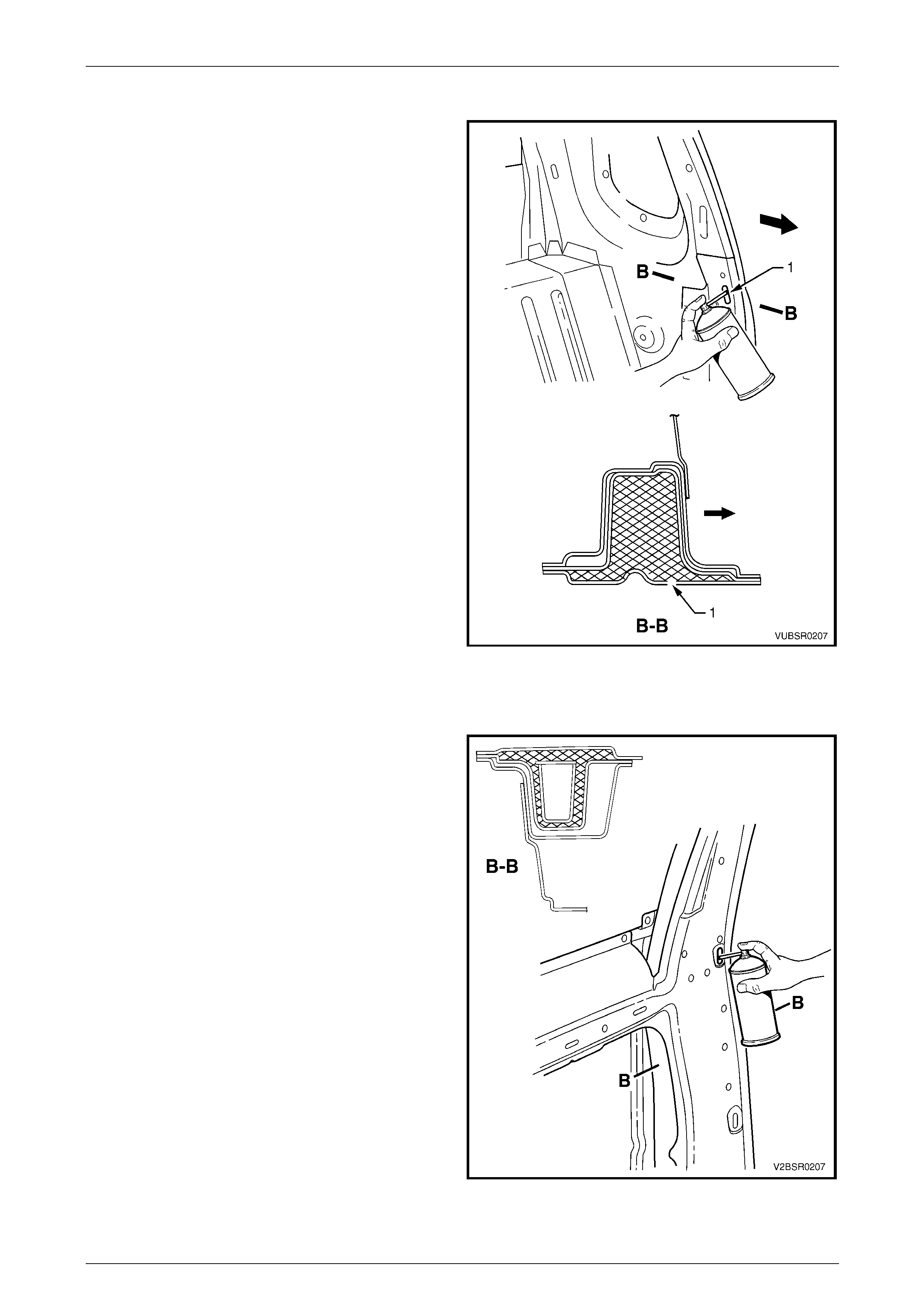
Body Lock Pillar, Utility
1 For the body lock pillars, inser t the nozzle into the trim
locating hole (1) which is above the foam blank.
2 Spray foam into the cavity bet wee n the lock pillar
reinforcement and quarter panel inner for several
seconds while drawing the no zzle out. Fill the area to
a height of approximately 50 mm.
3 Once cured, remove a small amount of foam from the
locating hole using a prob e to enable the trim stud to
seat correctly.
Figure 2 – 16
Rocker Panel, Utility
1 For the rocker panels, insert the nozzle into the in ner
rocker panel hole (1) within the fuel tank cavity.
2 Spray foam into the cavity bet wee n the door opening
frame, quarter panel inner and inner rocker panel for
several seconds for a length of appro xim ately 50 mm.
Figure 2 – 17