3 Body Construction Page 3-1
Page 3-1
Section 3
Body Construction
ATTENTION
Before performing any service operation or other procedure described in this Section, refer to Section 2
Precautions in this Supplement and Section 00 Warnings, Cautions and Notes in the MY2005 VZ Service
Information for correct workshop practices with regard to safety and/or property damage.
The structure of the body shell has been
developed using complex design and
development techniques. In addition to
meeting all required standards, the vehicle
body is also a critical part of the overall safety
systems. It is therefore imperative the repair
procedures described here are adhered to
during all vehicle body repairs.
1 General Description ...............................................................................................................................2
1.1 Body Structure Part Refinishing........................................................................................................................... 2
1.2 Anti-Corrosive Treatment...................................................................................................................................... 3
1.3 Paint Refinishing.................................................................................................................................................... 4
Panel Refinishing................................................................................................................................................... 4
Paint Code.............................................................................................................................................................. 4
2 Bumper Impact Bar Assemblies...........................................................................................................5
2.1 Front........................................................................................................................................................................ 5
Remove................................................................................................................................................................... 5
Reinstall.................................................................................................................................................................. 5
2.2 Rear......................................................................................................................................................................... 6
Remove................................................................................................................................................................... 6
Reinstall.................................................................................................................................................................. 6
3 Special Tools ..........................................................................................................................................7
4 Torque Wrench Specifications..............................................................................................................8

3 Body Construction Page 3-2
Page 3-2
1 General Description
This Section contains general body construction information relative to all body styles. Information specific to a body style
has been divided into sub-sections for each body style.
Each sub-section describes the body structure as a whole and prov ides a detailed break down of the body structure
components, key body dimensional measurements and body margin tolerances.
The various sealers and adhe sives used throughout the body are also described, as it is imperative that only the correct
materials are used for repairs.
The correct cavity wax, deadeners a nd paint refinishing techniques are also imperative if the veh icle is to be returned to
its original condition.
When replacing or repairin g a part or sub-assembly, care must be taken to ensure that correct alignment and strength of
unit as a whole is maintained. In some instances, major damage to the body or frame can be repaired more effectively
and economically by replacing a part or sub-assembly with a new one, rather than repairing the damaged part.
1.1 Body Structure Part Refinishing
The vehicle body structure is designed to meet or exceed many regulations, including crash performance and occupant
protection, etc. When replacing or repairin g a part or sub-assembly, care must be taken to ensure that correct alignment
and strength of unit as a whole is maintained.
In some instances, major damage to the body structure can be repaired more effectively and economically by replacing a
part or sub-assembly with a new one, rather than repairing the damaged part.
Spot welding is used extensiv ely for joining panels or assemblies, however special adhesives are playing an ever
increasing role in the joini ng of body structure components, either on their own or together with spot welds. Where
repairs are performed, it is imperative that effective rust proofing techniques, as outlined in the following paragraphs, be
observed.
It is for these reasons that qualified persons with suitable tr aining and qualificatio ns only perform the repair or
replacement of body structure components.

3 Body Construction Page 3-3
Page 3-3
1.2 Anti-Corrosive Treatment
Precoated and galvanised steel is used extensively for vari ous body structure components for increased corrosion
protection. Body panels such as the engin e hoo d, door and decklid outer panels are precoated on the inner surface of
the metal to improve corrosion protection. Other bod y structure members have complete double-sided galvanised
protection.
In addition, a rust preventative material (cavity wax) is sprayed after paint application to areas such as the interior
surfaces of doors, etc.
Any repair or replacement of panels, assemblies, etc. that disturb this anti-corrosive treatment must be resealed and
should be included as part of the repair or replacement operation.
Anti-corrosive compounds used for repairs should be light bodi ed materials designed to penetrate b etween metal-to-
metal surfaces such as pinch weld flanges and integral panel attaching poi nts.
All bare metal surfaces must be treated with metal conditioner and primed. These operations need to be carried out prior
to the application of sealers, waxes and sound deadeners. Attaching points of new replacement panels should be
resealed. The hemming flanges of replacement doors, liftgates, endgates and rear compartment lids will require
resealing.
Open joins that require bridging of the sealer to close a gap should be sealed with a heavy-b odied caulking material.
When colour applicatio n is required to restore repaired areas to original appearance, conventional refinishing
preparation, undercoat build-u p and colour application techniques should be employed.
When deadeners are disturbe d during damage repair, or a panel has been replaced, the deadener material must b e
replaced with an equivalent material. The location and pattern for replacement material can be determined by observing
the original deadener application outlines.
3 Body Construction Page 3-4
Page 3-4
1.3 Paint Refinishing
Panel Refinishing
Metal service replacement parts (or assembl ies) are p ainted with a black, high bake factor y primer. To ensure sound
adhesion of colour coats in service, the following refinish steps are necessary.
1 Clean part with a wax and grease remov ing solvent such as Prepsol.
2 Scuff-sand panel lightly with wet and dry number 400 pa per and water. Avoid cut throughs . Re-clean part, and then
apply sealer to entire part.
3 If the factory primer coat has been cut through, apply metal conditioner to the exposed bare metal. Follo w the
directions on container label.
4 Apply primer-surfacer to the entire part; allow to dry thoroughly before sandin g.
5 Sand primer-surfacer using wet and dry number 400 paper and water. Do not sand sealer.
6 Re-clean part.
7 Apply colour coats to parts as directed on the contain er la bel.
8 Follow directions on cont ainer label for dryin g time before compounding.
9 Compound part by hand or with power equipment.
10 Non-sealing polish may be applied after rub-out if desired. Waxes however, should not b e app lied until the paint
finish has aged for at least two months. NOTE
Always follow the paint manufacturer’s
recommendations to ensure a high quality
durable finish is achieved.
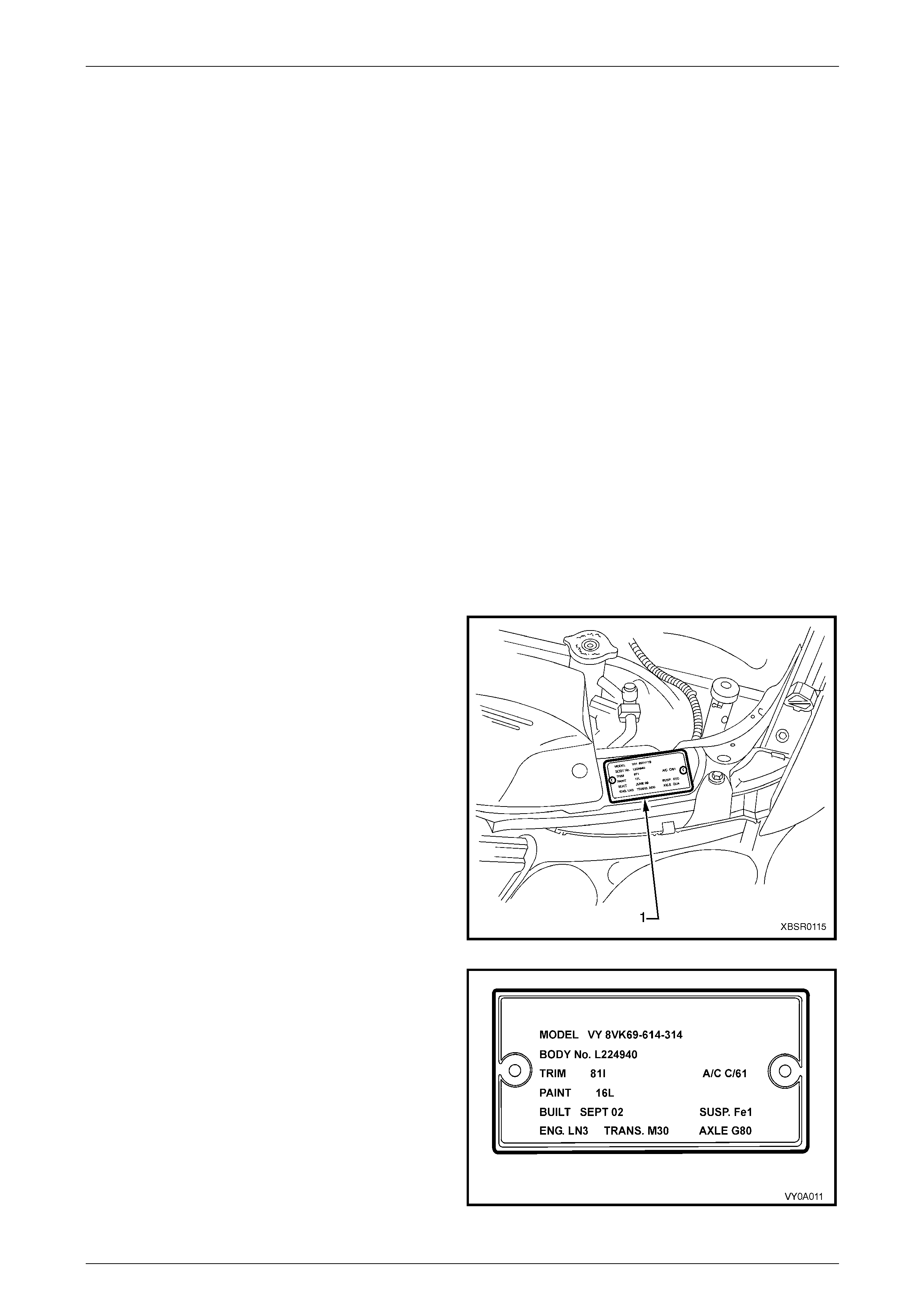
Paint Code
The Paint Code for the vehicle can be found on the Body
and Option Identification Plate (1).
Figure 3 – 1
The Paint Code enables a refinish paint to be matched with
the original paint colour. NOTE
The paint on the vehicle may not exactly match
the original colour due to fade, in which case
paint colour matching will be required. As this is
an acquired skill, it is a task that must be
performed by qualified individuals.
Figure 3 – 2
3 Body Construction Page 3-5
Page 3-5
2 Bumper Impact Bar Assemblies
The bumper impact bar assemblies not only act as a mount and support for the bumper fascias, but are also critical in
the dispersion of crash energ y. Hence, the y play an inte gral role in the operation of the vehicle’s safety systems. Repair
of the bar assemblies should be limited to replacement, as straightening and/or heating can weaken a bar assembly,
potentially resulting in incorrect airbag and se atbelt pretensioner operation.
2.1 Front
Remove
1 Remove the front bumper fascia assembly, refer to Section 1D Bumper Bars in the Service Information.
2 If fitted, remove the radiator air lower baffle, refer to Section 6B1 Engine Cooling in the Service Information.
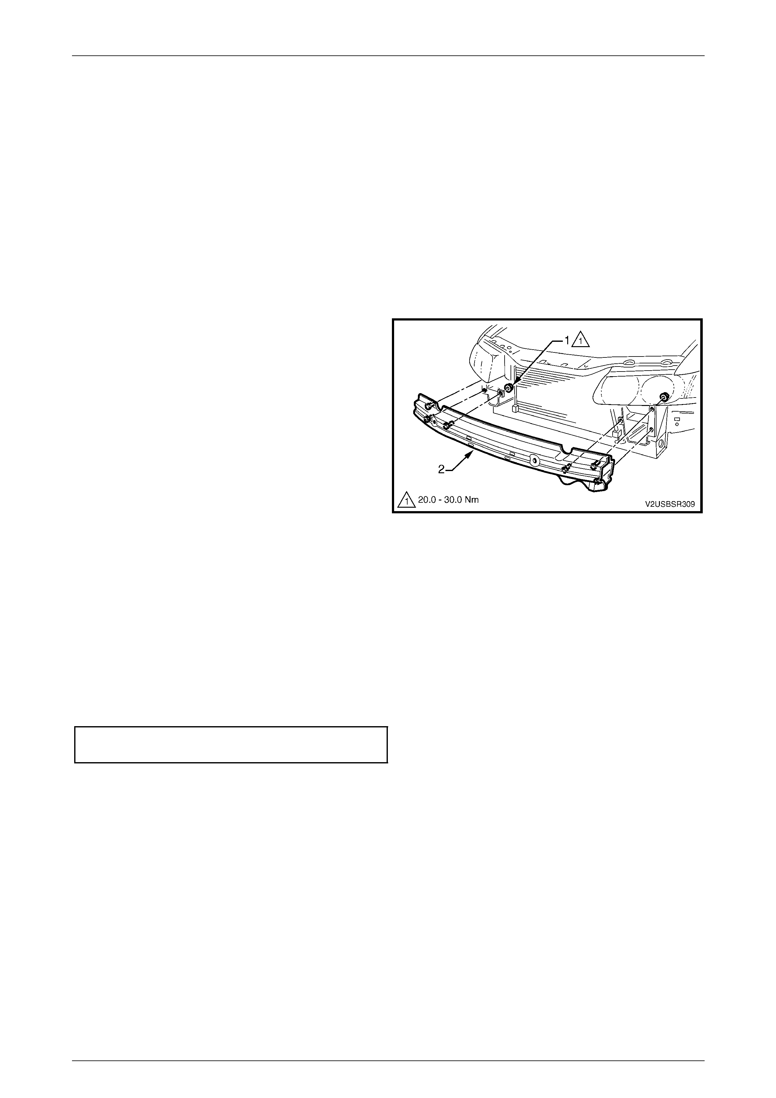
3 Remove the nuts (1), three places each side, attaching
the bar assembly (2) to the vehicle.
4 Remove the bar assembly.
Figure 3 – 3
Reinstall
NOTE
Check the vehicle’s front body dimensions as
required to ensure correct alignment, refer to
Section 1A2 Body Dimensions.
1 Fit the bar assembly in position and attach each nut. Do n ot tighten.
2 Ensure the bar assembly is correctl y pos itioned centrally and tighten the nuts to the specified torque.
Front bumper impact bar assembly
attaching nut torque specification............20.0 – 30.0 Nm
3 Refit the front bumper fascia assembly, refer to Section 1D Bumper Bars in the Service Information.
3 Body Construction Page 3-6
Page 3-6
2.2 Rear
Remove
1 Remove the rear bumper fascia assembly, refer to Section 1D Bumper Bars Service Information.
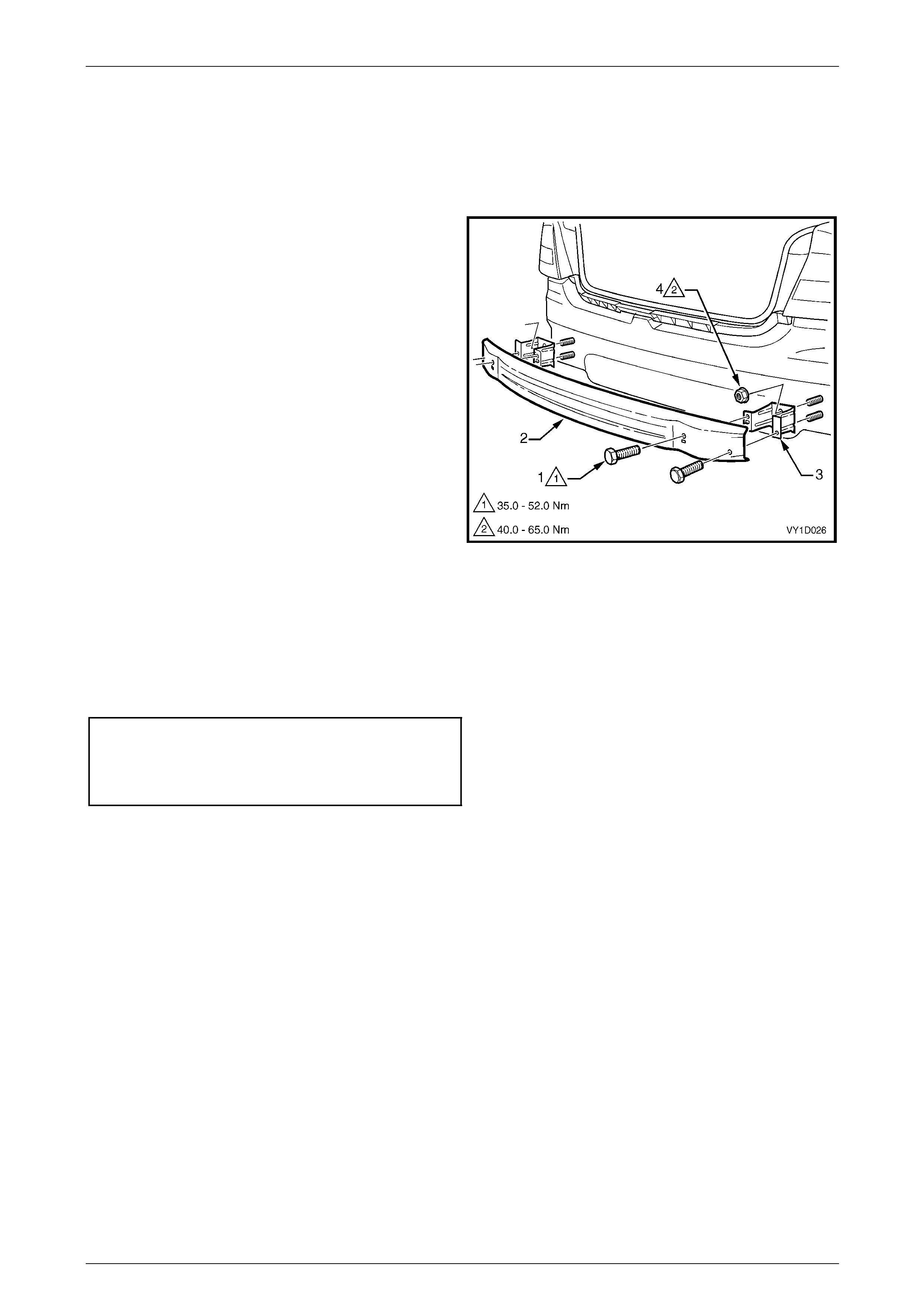
2 Remove the screws (1), two places each side,
attaching the rear bumper im pact bar (2) to the rear
bumper impact bar bracket assembly (3).
3 Remove the bar.
4 If required, remove the two nuts (4), attaching the
bracket assembly to the vehicle and remove the
bracket.
Figure 3 – 4
Reinstall
1 Fit the bracket assemblies in position and attach the nuts. Tighten to the specified torque.
2 Fit the bar to the bracket assemblies and fit each screw. Do not tighten.
3 When all screws are installed, check the bar is centralised. Tighten the bolts to the specified torque.
Rear bumper impact bar bracket assembly
attaching nut torque specification............49.0 – 65.0 Nm
Rear bumper impact bar attaching
screw torque specification.......................35.0 – 52.0 Nm
3 Body Construction Page 3-7
Page 3-7
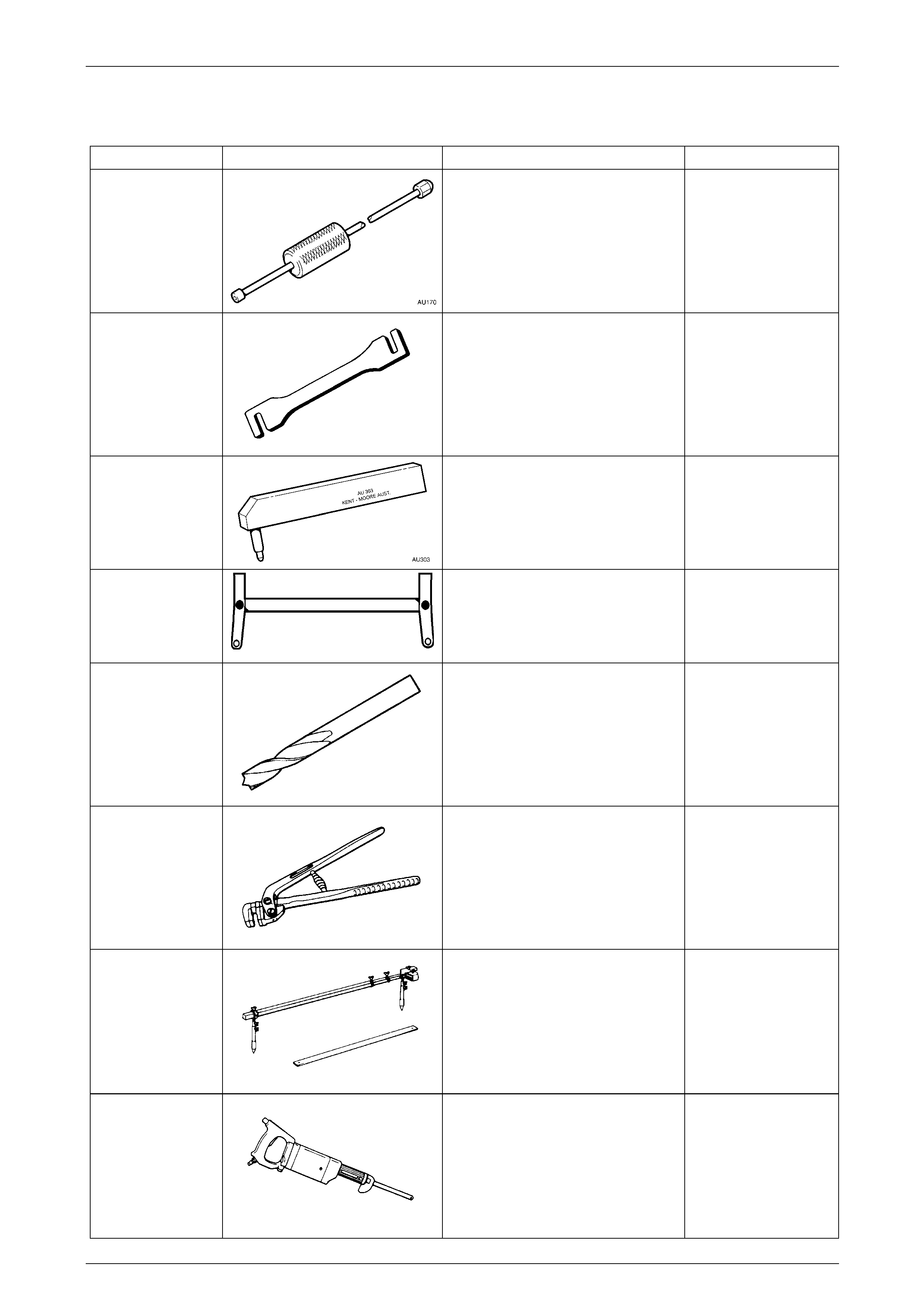
3 Special Tools
Tool Number Illustration Description Tool Classification
AU170 Door Hinge Sleeve Remover
Used for removing door hinge pivot
sleeves
AU184 Door Hinge Setting Tool
Used to adjust door alignment.
AU303
Door Hinge Sleeve Installer
Used to install door hinge piv ot
sleeves
AU458
Rear Crossmember Centring Tool
Used when any servic e operation
requires removal / reinstallation of
rear suspension frame assembly, or
when checking rear end alignment.
N/A Spot Cutting Tool
Commercially available
Used for separating spot welds
N/A Flanging Tool
Commercially available
Used for making a joggle to form a lap
joint on overlapping panels.
N/A Tracking Gauge
Commercially available
Used for measuring body dimensions
N/A Power Saw
Commercially available
Used for cutting panels. An angle
grinder may also be used when
deemed more appropri ate for the task

3 Body Construction Page 3-8
Page 3-8
4 Torque Wrench Specifications
Front Bumper Impact Bar Assembly Attaching Nut...................20.0 – 30.0 Nm
Rear Bumper Impact Bar Bracket Assembly Attaching Nut.......49.0 – 65.0 Nm
Rear Bumper Impact Bar Attaching Screw................................35.0 – 52.0 Nm