
3C Body Construction – Utility Page 3C-1
Page 3C-1
Section 3C
Body Construction – Utility
ATTENTION
Before performing any service operation or other procedure described in this Section, refer to Section 2
Precautions in this Supplement and Section 00 Warnings, Cautions and Notes in the MY2005 VZ Service
Information for correct workshop practices with regard to safety and/or property damage.
The structure of the body shell has been
developed using complex design and
development techniques. In addition to
meeting all required standards, the vehicle
body is also a critical part of the overall safety
systems. It is therefore imperative the repair
procedures described here are adhered to
during all vehicle body repairs.
1 General Description ...............................................................................................................................3
2 Body Structure Panels...........................................................................................................................4
2.1 Front End and Underbody..................................................................................................................................... 5
2.2 Upperbody Structure............................................................................................................................................. 7
2.3 Body Assembly...................................................................................................................................................... 9
3 Body Dimensions.................................................................................................................................11
3.1 Underbody Dimensions – Projected .................................................................................................................. 11
3.2 Upperbody Dimensions – Actual........................................................................................................................ 13
Front...................................................................................................................................................................... 13
Side and Interior................................................................................................................................................... 14
Rear....................................................................................................................................................................... 15
4 Body Margins........................................................................................................................................16
5 Body Sealing, Adhesives and Deadeners..........................................................................................20
5.1 Acrylic Spot Weld Sealer (Item 2)....................................................................................................................... 22
Acrylic Spot Weld Sealer (Item 2) Continued .................................................................................................... 23
Acrylic Spot Weld Sealer (Item 2) Continued .................................................................................................... 24
Acrylic Spot Weld Sealer (Item 2) Continued .................................................................................................... 25
Acrylic Spot Weld Sealer (Item 2) Continued .................................................................................................... 26
5.2 Joint Sealer (Item 3)............................................................................................................................................. 27
Joint Sealer (Item 3) Continued.......................................................................................................................... 28
Joint Sealer (Item 3) Continued.......................................................................................................................... 29
Joint Sealer (Item 3) Continued.......................................................................................................................... 30
Joint Sealer (Item 3) Continued.......................................................................................................................... 31
Joint Sealer (Item 3) Continued.......................................................................................................................... 32
Joint Sealer (Item 3) Continued and Hand Putty (Item 4) ................................................................................. 33

3C Body Construction – Utility Page 3C-2
Page 3C-2
5.3 Adhesive – Anti Flutter (Item 5).......................................................................................................................... 34
5.4 Adhesive – Structural (Item 6) ............................................................................................................................ 35
5.5 Spray-on Deadener.............................................................................................................................................. 37
5.6 Deadener Panels and Insulators......................................................................................................................... 38
5.7 Fusible Reinforcement Patches.......................................................................................................................... 41
Replace................................................................................................................................................................. 41
6 Cavity Wax ............................................................................................................................................42

3C Body Construction – Utility Page 3C-3
Page 3C-3
1 General Description
This Section contains body construction information specific to Utility vehicles. For body construction information relevant
to all models, refer to Section 3 Body Construction.
The various sealers and adhesives used throughout the body are also described as it is imperative that only the correct
materials are used for repairs.
The correct cavity wax, deadeners a nd paint refinishing techniques are also imperative if the veh icle is to be returned to
its original condition.
When replacing or repairin g a part or sub-assembly, care must be taken to ensure that correct alignment and strength of
unit as a whole is maintained. In some instances, major damage to the body or frame can be repaired more effectively
and economically by replacing a part or sub-assembly with a new one, rather than repairing the damaged part.

3C Body Construction – Utility Page 3C-4
Page 3C-4
2 Body Structure Panels
The following tables and illustrations describe the body structure assemblies and panels that are available for service
replacement.
NOTE
Always refer to an Authorised Retailer for spare
parts availability configurations.
3C Body Construction – Utility Page 3C-5
Page 3C-5
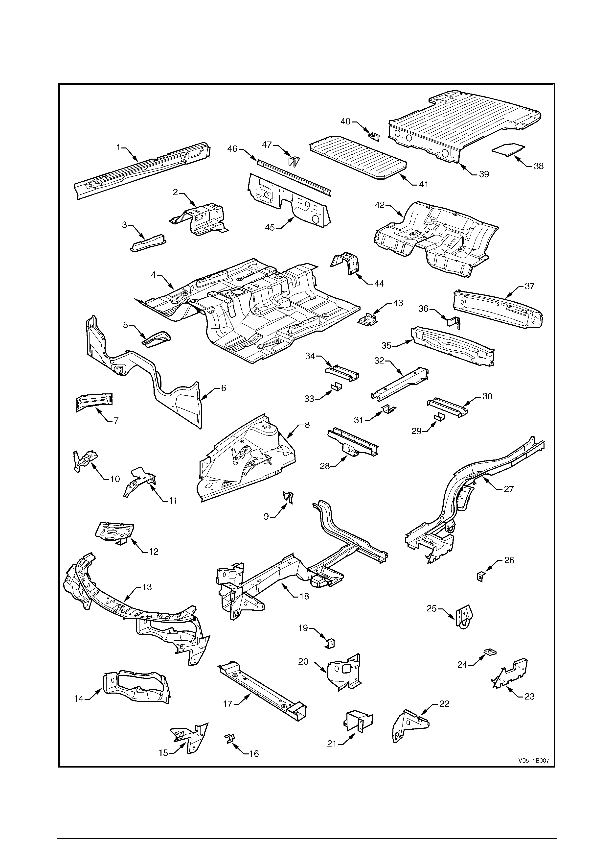
2.1 Front End and Underbody
Figure 3C – 1

3C Body Construction – Utility Page 3C-6
Page 3C-6
Legend
1 Inner Rocker Panel Assembly, Right-hand / Left-hand
2 Seat Inner Bracket Assembly
3 Seat Outer Bracket Assembly, Right-hand / Left-hand
4 Front Floor Panel Assembly
5 Transmission Support Bracket, Right-hand / Left-hand
6 Front Floor Panel Extension
7 Front Side Rail Brace, Right-hand / Left-hand
8 Front Wheelhouse Panel Assembly, Right-hand / Left-hand
9 Horn Bracket Assembly, Left-hand only
10 Relay Housing Bracket, Right-hand only
11 ABS Modulator Bracket Assembly, Right-hand only
12 Battery Tray Assembly, Right-hand only
13 Front End Panel Assembly
14 Headlamp Panel, Left-hand / Right-hand
15 Headlamp and Front Fascia Mount Bracket, Left-hand /
Right-hand
16 Fender Front Lower Bracket, Left-hand / Right-hand
17 Radiator Lower Support Assembly
18 Front Side Rail Assembly, Left-hand / Right-hand
19 Radiator Side Mounting Bracket, Left-hand / Right-hand
20 Front Wheelhouse Bracket Assembly, Left-hand / Right-
hand
21 Front Bumper Impact Bar Bracket, Left-hand / Right-hand
22 Front Wheelhouse Panel Bracket, Left-hand / Right-hand
23 Rear Floor Panel Outer Extension, Left-hand / Right-hand
24 Rear Suspension Support Mount Plate, Left-hand / Right-
hand
25 Rear Tie Down Assembly, Left-hand / Right-hand
26 Rear Brake Hose Bracket, Left-hand / Right-hand
27 Rear Side Rail Assembly, Left-hand / Right-hand
28 Crossmember Assembly No. 2
29 Spare Wheel Support, Left-hand
30 Load Floor Reinforcement Rail, Left-hand
31 Spare Wheel Support
32 Load Floor Centre Rail Assembly
33 Spare Wheel Support, Right-hand
34 Load Floor Reinforcement Rail, Right-hand
35 Rear End Panel
36 Endgate Hinge Bracket Assembly (Body side), Right-hand /
Left-hand
37 Rear End Lower Panel
38 Load Floor Panel Reinforcement, Left-hand / Right-hand
39 Load Floor Panel
40 Fuel Tank Bracket Assembly, Right-hand / Left-hand
41 Load Floor Front Panel Assembly
42 Rear Floor Panel Assembly
43 Jack Stowage Bracket Assembly, Left-hand only
44 Propeller Shaft Hanger Assembly
45 Front Floor Rear Extension Assembly
46 Front Floor Rear Extension Reinforcement
47 Fuel Tank Bracket Assembly, Right-hand / Left-hand
3C Body Construction – Utility Page 3C-7
Page 3C-7
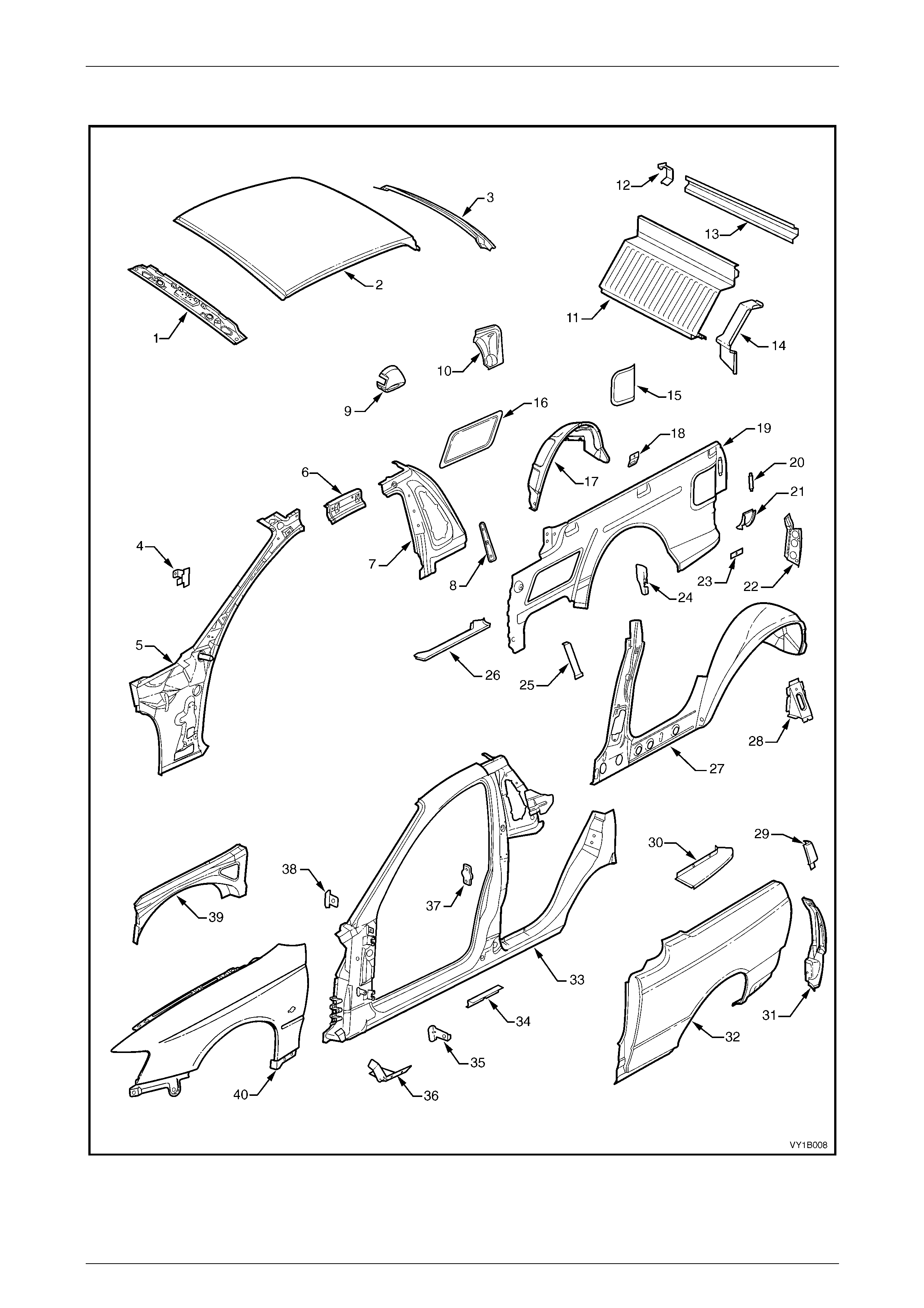
2.2 Upperbody Structure
Figure 3C – 2

3C Body Construction – Utility Page 3C-8
Page 3C-8
Legend
1 Roof Front Header Panel
2 Roof Panel
3 Roof Rear Panel
4 Hinge Pillar Trim Panel Bracket, Left-hand / Right-hand
5 Hinge Pillar Inner Panel Assembly, Left-hand / Right-
hand
6 Quarter Panel Inner Extension, Left-hand / Right-hand
7 Side Inner Upper Panel, Left-hand / Right-hand
8 Seat Belt Guide Anchor Plate Assembly, Left-hand /
Right-hand
9 Fuel Filler Pipe Housing, Right-hand only
10 Rear Wheelhouse Outer Extension, Right-hand only
11 Front Seat Back Panel
12 Load Compartment Extension Panel Bracket, Right-hand
only
13 Load Compartment Extension Outer Panel
14 Front Seat Back Panel Outer, Left-hand / Right-hand
15 Rear Inner Side Panel Cover, Left-hand / Right-hand
16 Front Inner Side Panel Cover, Left-hand / Right-hand
17 Rear Wheelhouse Inner Panel, Left-hand / Right-hand
18 Cargo Tie-Down Bracket (three places), Left-hand /
Right-hand
19 Side Inner Upper Panel, Left-hand / Right-hand
20 Endgate Striker Anchor Plate Retainer, Left-hand / Right-
hand
21 Quarter Lower Rear Panel, Left-hand / Right-hand
22 Quarter Inner Lower Rear Extension, Left-hand / Right-hand
23 Cargo Tie-Down Anchor Plate Assembly (three places), Left-
hand / Right-hand
24 Rear Wheelhouse Bracket, Left-hand / Right-hand
25 Load Floor Panel Outer Reinforcement, Left-hand / Right-hand
26 Load Floor Panel Outer Extension, Left-hand / Right-hand
27 Quarter Panel Inner Assembly, Left-hand / Right-hand
28 Quarter Inner and Rear Wheelhouse Brace, Left-hand / Right-
hand
29 Quarter Panel Upper Extension, Left-hand / Right-hand
30 Quarter Outer Lower Rear Panel, Left-hand / Right-hand
31 Quarter Panel Extension, Left-hand / Right-hand
32 Rear Quarter Panel, Left-hand / Right-hand
33 Door Opening Frame Assembly, Left-hand / Right-hand
34 Underbody Jacking Locator, Left-hand / Right-hand
35 Fender Rear Bracket, Left-hand / Right-hand
36 Fender Lower Rear Bracket, Left-hand / Right-hand
37 Front Door Striker Anchor Plate, Left-hand / Right-hand
38 Fender Upper Rear Bracket, Left-hand / Right-hand
39 Front Wheelhouse Panel Upper Side Rail, Left-hand / Right-
hand
40 Front Fender, Left-hand / Right-hand*
* Some models are fitted with a front fender centre moulding assembly. In this instance a different front fender is fitted.
3C Body Construction – Utility Page 3C-9
Page 3C-9
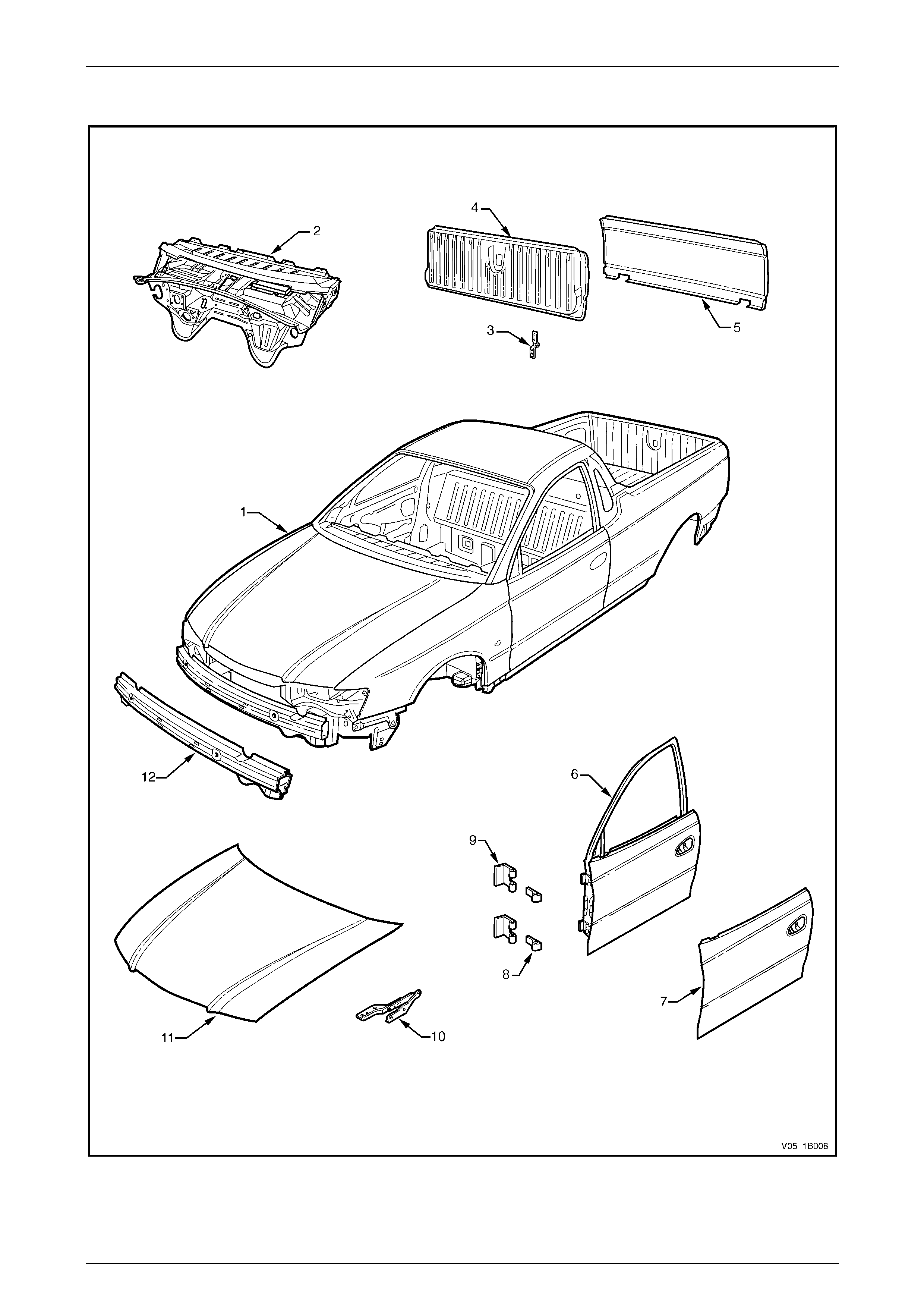
2.3 Body Assembly
Figure 3C 3

3C Body Construction – Utility Page 3C-10
Page 3C-10
Legend
1 Body Assembly
2 Dash Panel Assembly
3 Endgate Hinge Assembly, Left-hand / Right-hand
4 Endgate Assembly
5 Endgate Outer Panel
6 Front Door Assembly, Left-hand / Right-hand
7 Front Door Outer Panel, Left-hand / Right-hand
8 Front Door Hinge (Door Side), Left-hand / Right-hand
9 Front Door Hinge (Body Side), Left-hand / Right-hand
10 Hood Hinge Assembly, Left-hand / Right-hand
11 Hood Assembly
12 Front Bumper Impact Bar Assembly
3C Body Construction – Utility Page 3C-11
Page 3C-11
3 Body Dimensions
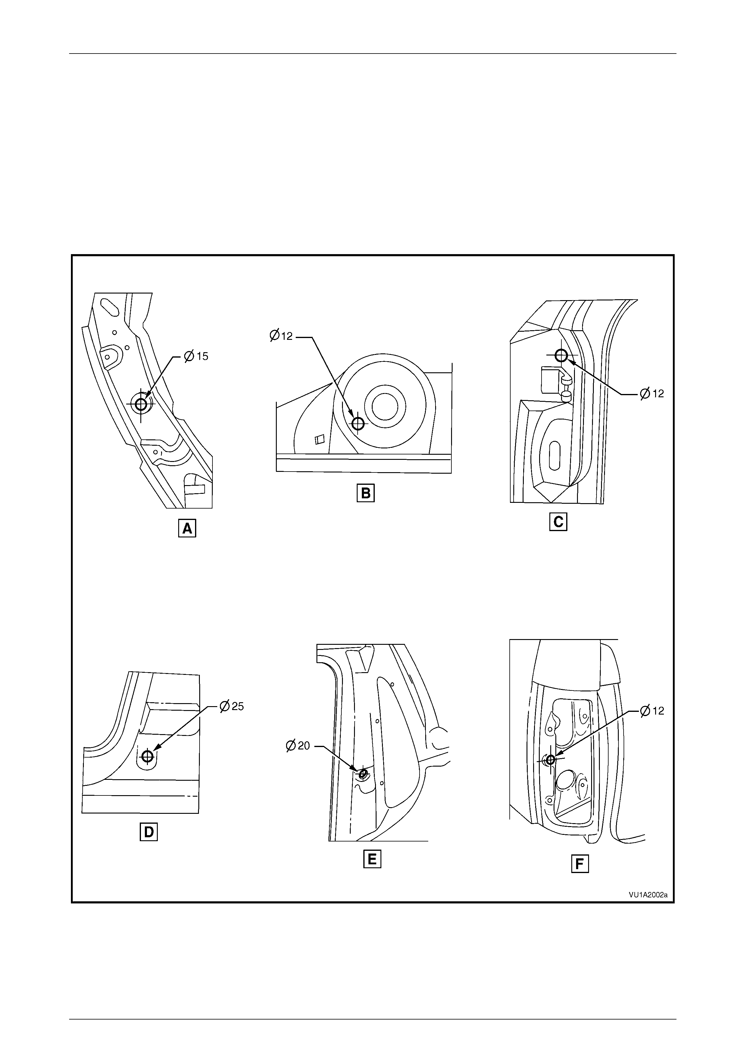
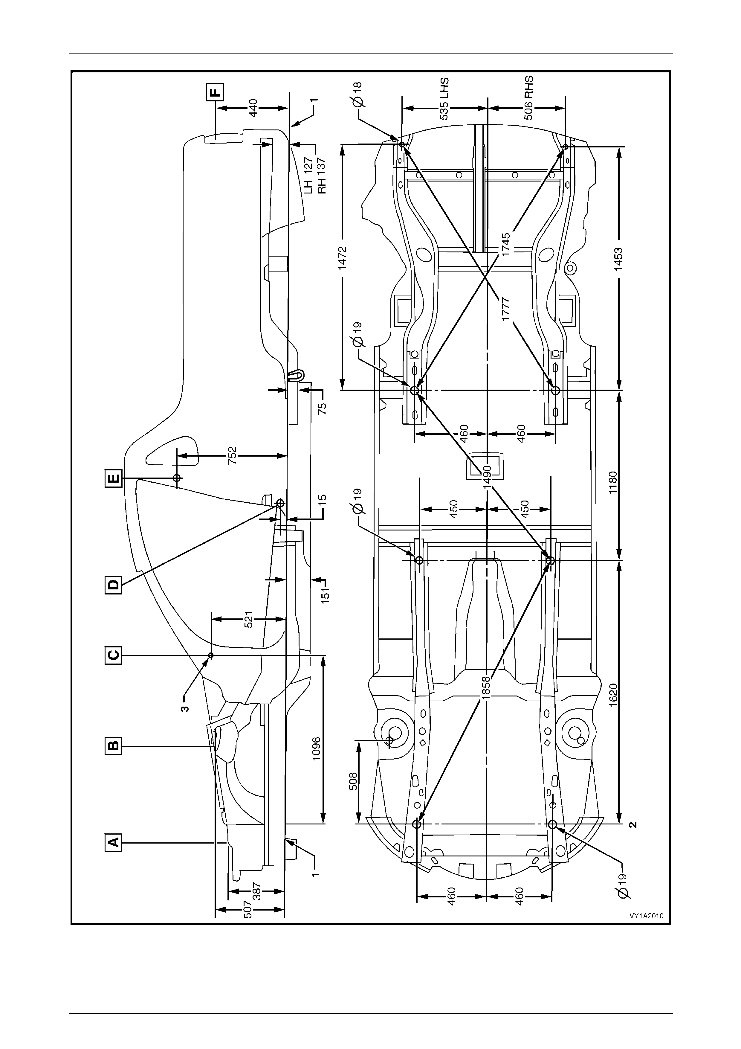
3.1 Underbody Dimensions – Projected
All dimensions are given in mm and are measured from the centre of hol es, on the outer side of the metal surface.
The main datum surface (1) is the underside of the front side rail assembl y, refer to Figure 3C – 5.
The main datum hole (2) is a 19 mm hole on the underside of the front side rail assembly, refer to Figure 3C – 5.
The dash panel assembly attaching hole (3) in Figure 3C – 5 is the datum hole also depicted at View C in Figure 3C – 4.
Figure 3C – 4
3C Body Construction – Utility Page 3C-12
Page 3C-12
Figure 3C – 5
3C Body Construction – Utility Page 3C-13
Page 3C-13
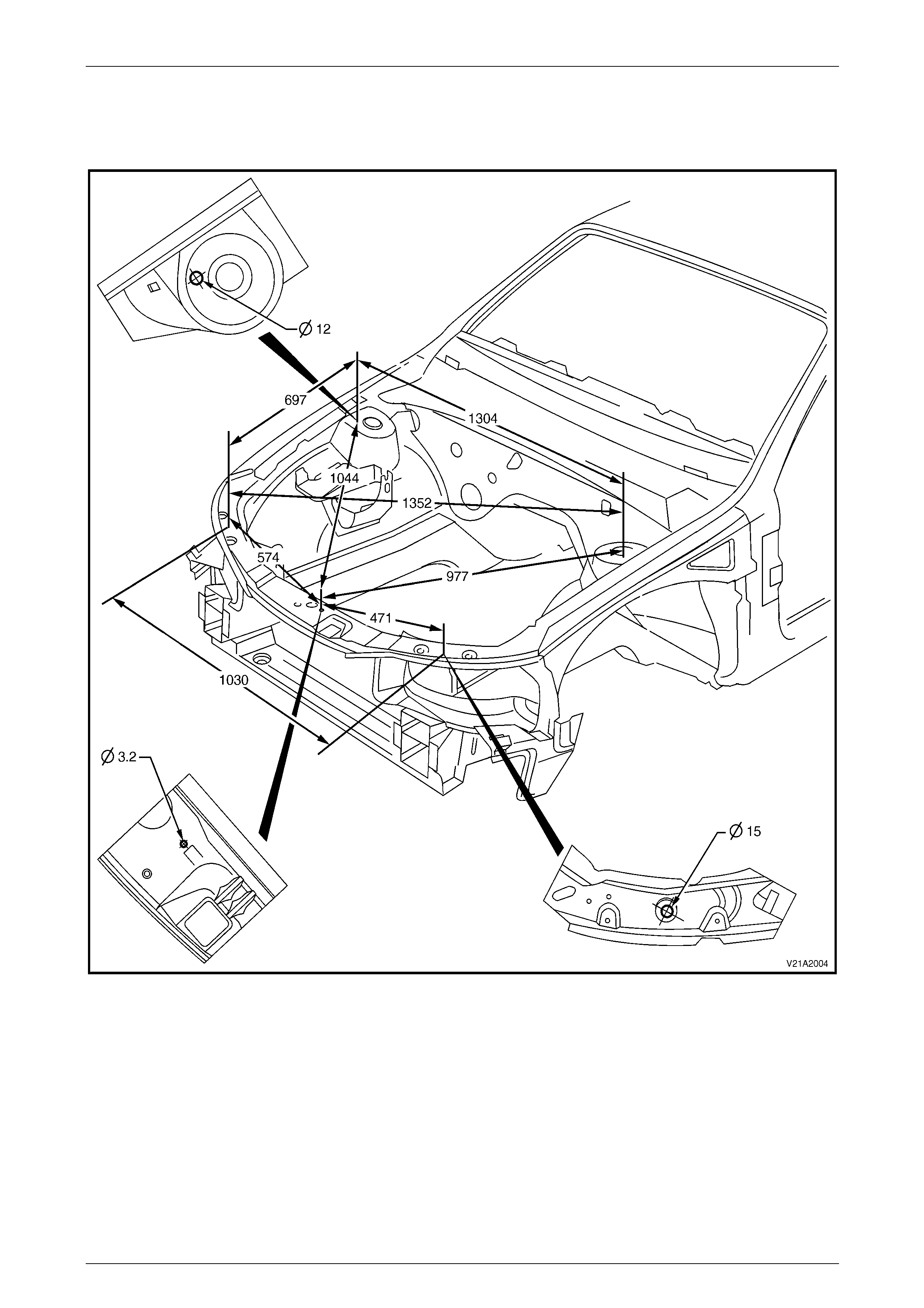
3.2 Upperbody Dimensions – Actual
Front
Figure 3C – 6
3C Body Construction – Utility Page 3C-14
Page 3C-14
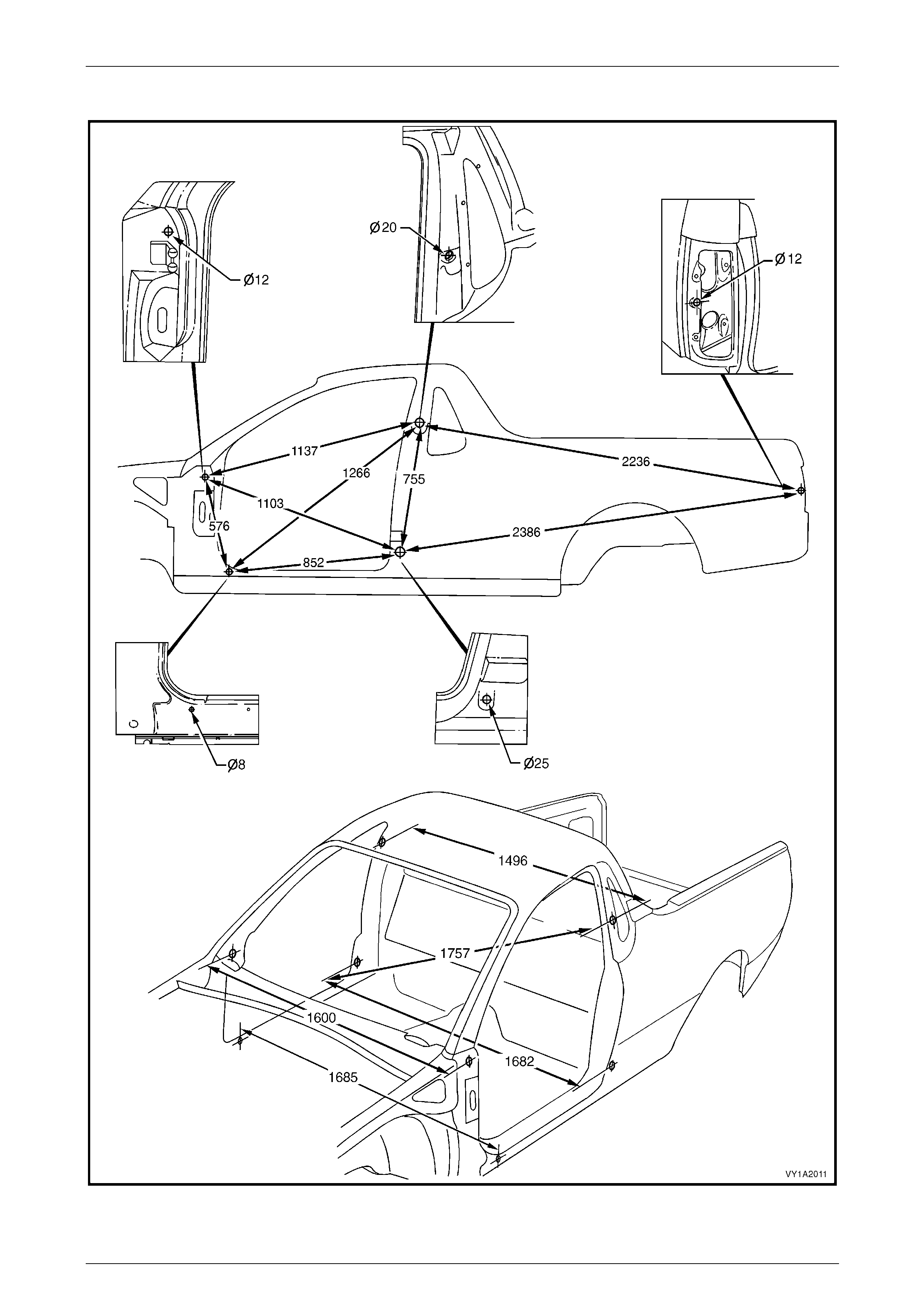
Side and Interior
Figure 3C – 7
3C Body Construction – Utility Page 3C-15
Page 3C-15
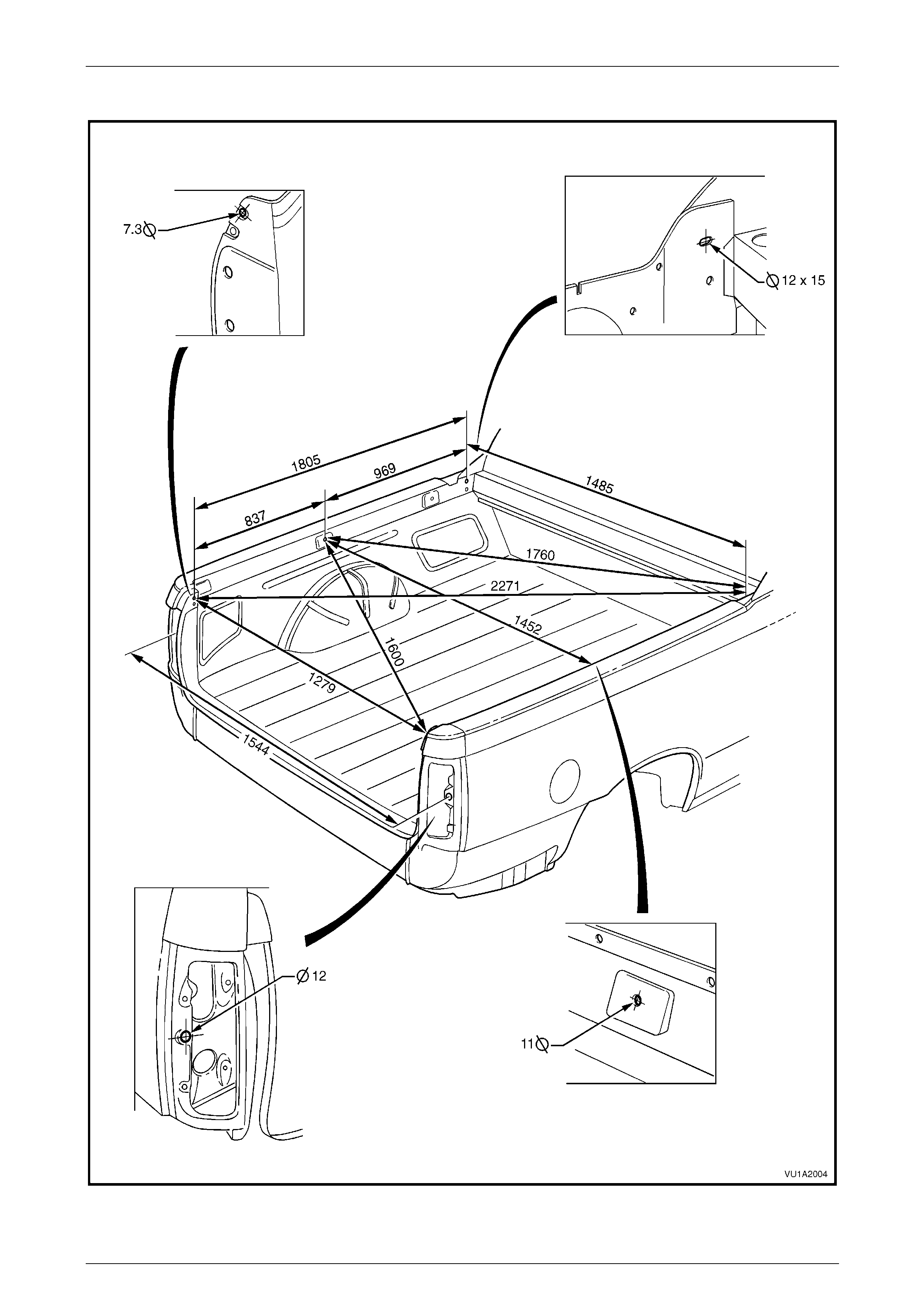
Rear
Figure 3C – 8

3C Body Construction – Utility Page 3C-16
Page 3C-16
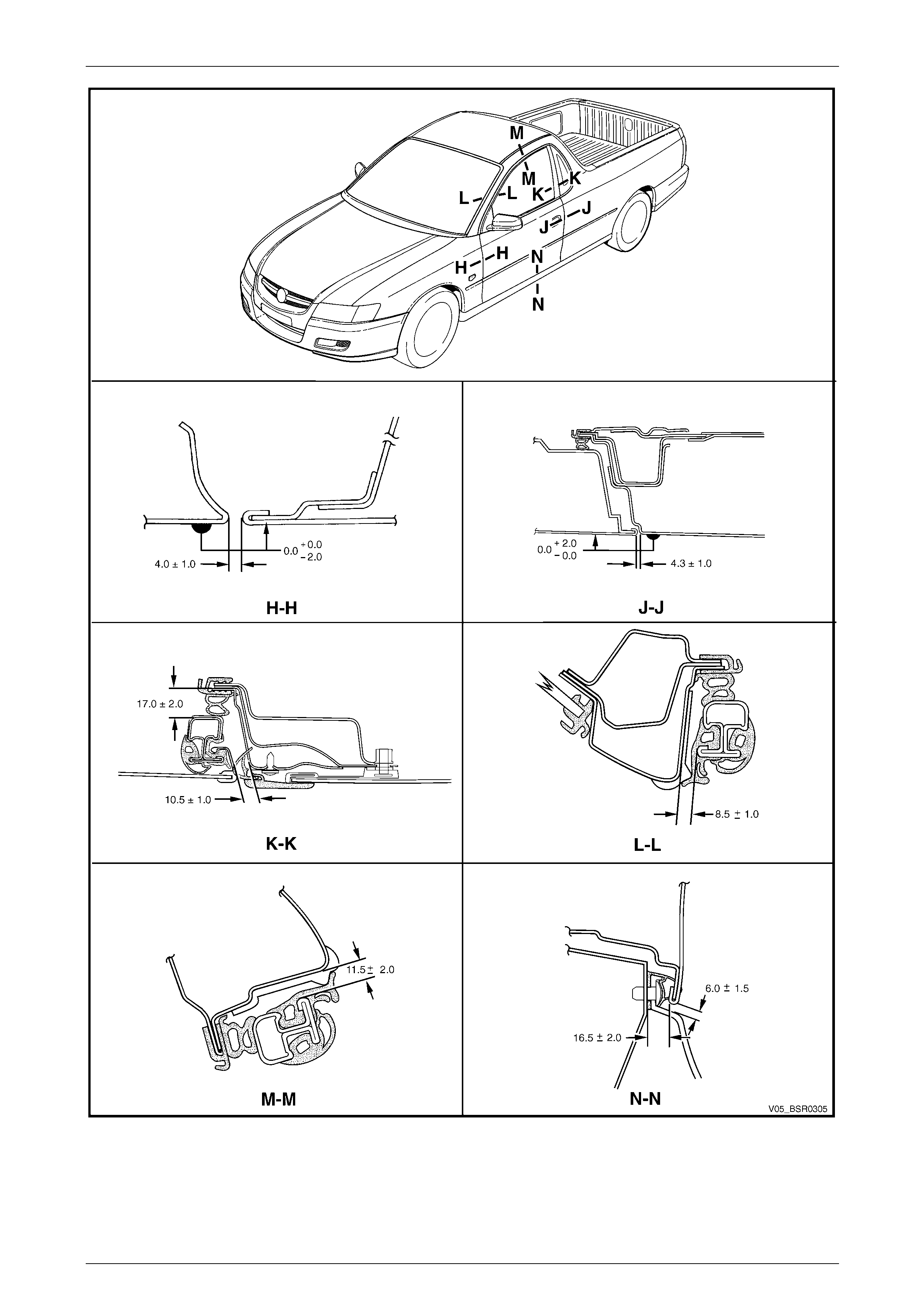
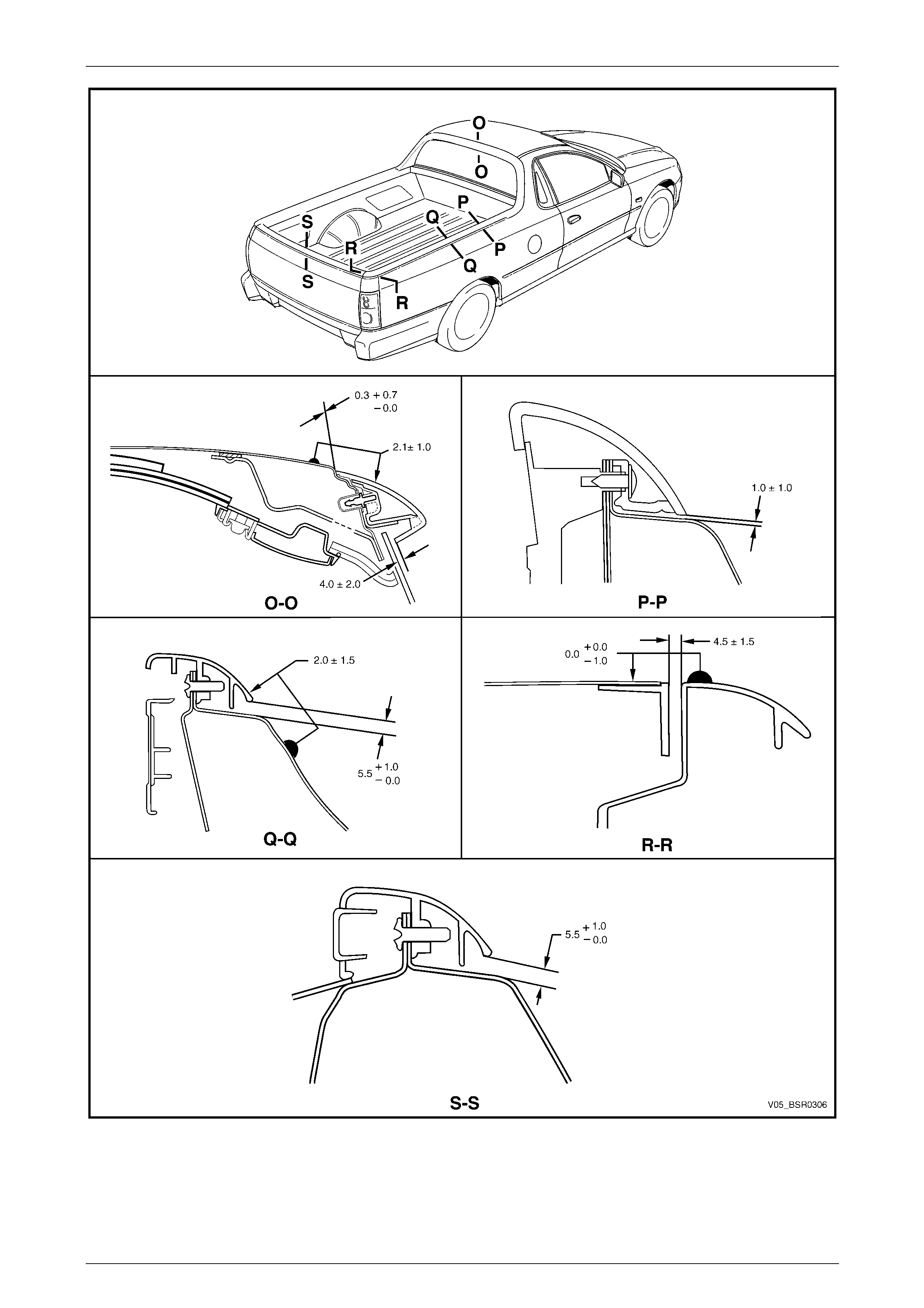
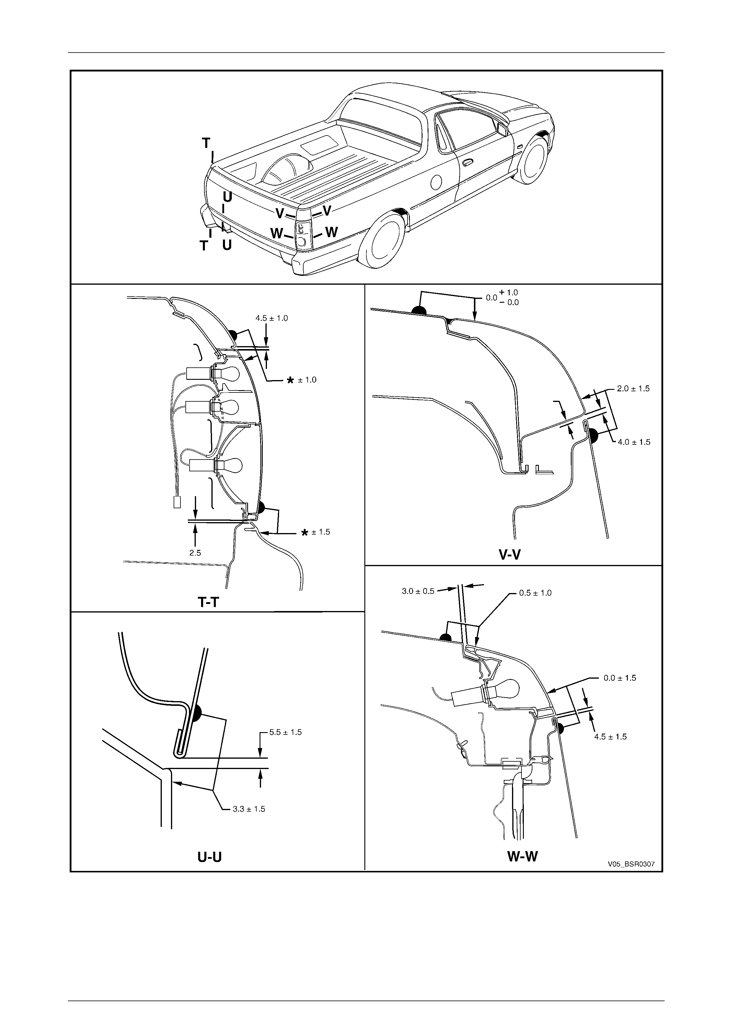
4 Body Margins
Figure 3C – 9
3C Body Construction – Utility Page 3C-17
Page 3C-17
Figure 3C – 10
3C Body Construction – Utility Page 3C-18
Page 3C-18
Figure 3C – 11
3C Body Construction – Utility Page 3C-19
Page 3C-19
Figure 3C – 12

3C Body Construction – Utility Page 3C-20
Page 3C-20
5 Body Sealing, Adhesives and
Deadeners
The commercially available products listed
below will meet the required standards. Other
products may be available that meet the
performance characteristics, however before
their use, the product manufacturer should be
contacted to check its suitability.
This Section details the sealers, adhesives and deadeners used in the Utility body shell. It is imperative that the correct
materials are used and the directions on the product al ways be followed.
NOTE
When replacing any sealer, adhesive or
deadener, ensure the finish meets that of the
original application.
Weld Through Primer (Item 1)
Although not used in manufacture, Weld Through Primer is recommended for all service repair lap and flange joints
where Acrylic Spot Weld Sealer (Item 2) is not used. Weld Through Primer aids in corrosion protection of the joint.
Acrylic Spot Weld Sealer (Item 2)
Used in joints that require sealing additional to Joint Sealer (Item 3). It is applied to the joint flange prior to the mating of
panels. Refer to Figure 3C – 13 and Figur e 3C – 17.
Joint Sealer (Item 3)
Primarily used for sealing joints to achieve a watertig ht seal. It seals notches, cut-outs and holes. Joint se aler should be
applied after priming, prior to application of the top coat. Refer to Figure 3C – 18 – Figur e 3C – 24.
Hand Putty (Item 4)
Hand putty, also known as caulking compound, is used in the areas marked * in Figure 3 C – 24.
Adhesive – Anti-Flutter (Item 5)
While used as a filler between an inner and outer panel to reduce panel flex, Anti-Flutter adhesive also aids rigidity and
assists in dispersing loads over a larger area. Refer to Figure 3C – 25 for locations.

3C Body Construction – Utility Page 3C-21
Page 3C-21
Adhesive – Structural (Item 6)
Critical to the strength and rigidity of the vehicle, the correct adhesive must be used for service repairs. Using an
adhesive that is too weak will reduc e the performance of the joint. Using an adhesive that is too strong can also effect the
performance of the joint, compromising the ve hicle’s crash performance and safety system’s operation. This adhesive is
a 2-part system. Refer to Figure 3C – 26 and Figure 3C – 27 for locati ons.
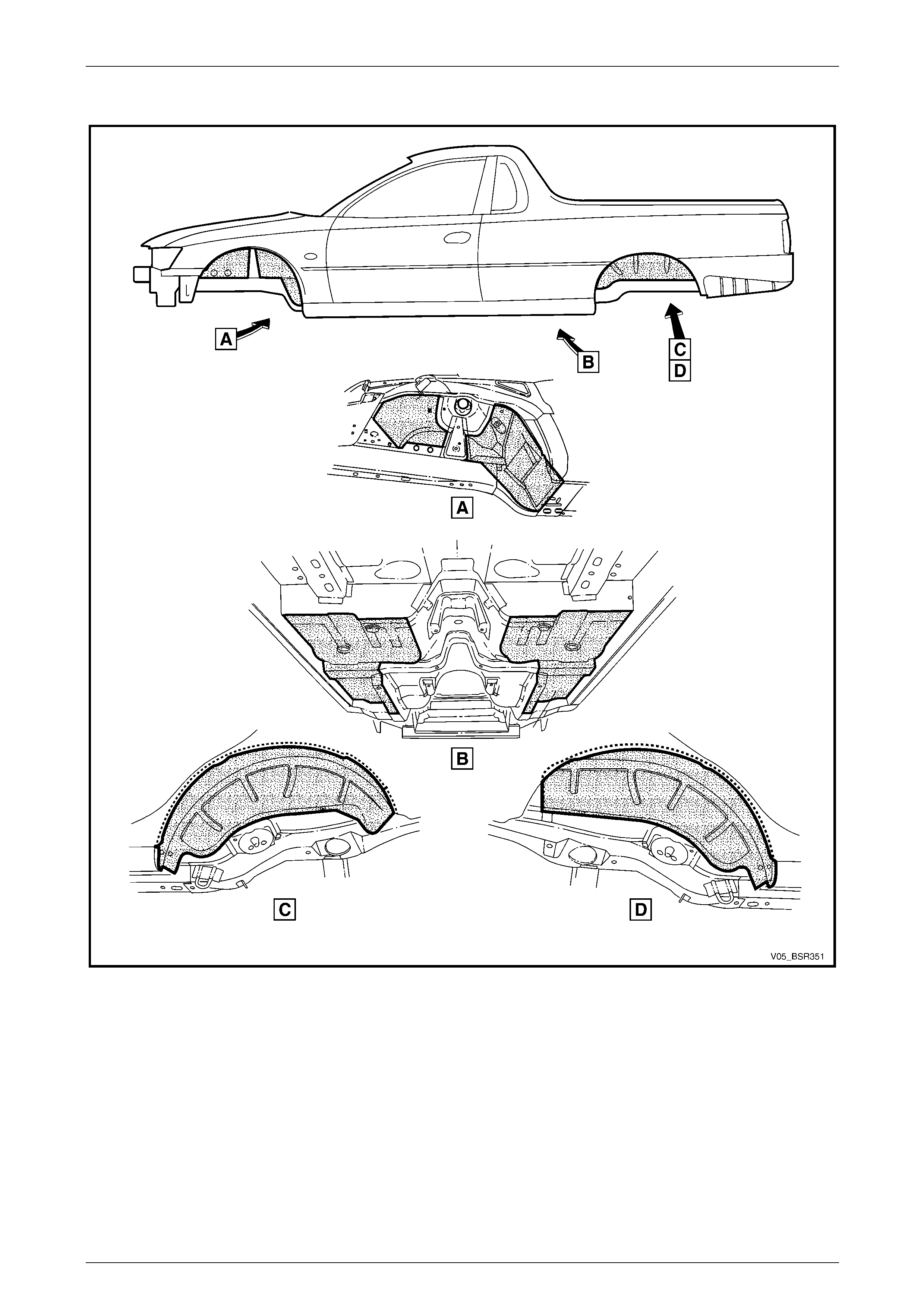
Spray-on Deadener (Item 7)
This deadener is spra yed onto the body shell after painting. It is used in the wheel-wells and on the under side of the
floor pan. A minimum thickness of 1.5 mm is required in these app lications. Refer to Figure 3C – 28 for locations.
Deadener Panels
Deadener panels are sold pre-cut as service parts. They are installed with the coloured side up and diamond embossed
side down. The panels are installe d prior to painting and some are heat fused to the bod y shell. Refer to Figure 3C – 29
– Figure 3C – 31 for locations.
Commercially Available Sea ler, Adhesive and Deaden er Equivalents
Item No. Item Name Manufacturer Product Name
1 Weld Through Primer Refer to supplier –
2 Acrylic Spot Weld Sealer Lord (Fusor) Fusor #800 / #801
3 Joint Sealer Sprayable: Lord (Fusor)
Extruded beads: Lord (Fusor)
3M
Visible Seams
-self levelling: Lord (Fusor)
3M
-non sag: Lord (Fusor)
3M
Fusor #802
Fusor #800 / #801
Automix 8308
Fusor #122 / #125
Automix 8307
Fusor #123 / #126
Automix 8308
4 Hand Putty Lord (Fusor) Fusor #800 / #801
Automix 8307
5 Adhesive – Anti Flutter Lord (Fusor) Fusor #124
6 Adhesive – Structural (Two-Part) Lord (Fusor)
3M Fusor #108 B
Automix 8115
7 Spray-on Deadener Henkel Terophon 2000-13
NOTE
Special tools may be required to apply some
materials, refer to an supplier for further
information.
3C Body Construction – Utility Page 3C-22
Page 3C-22
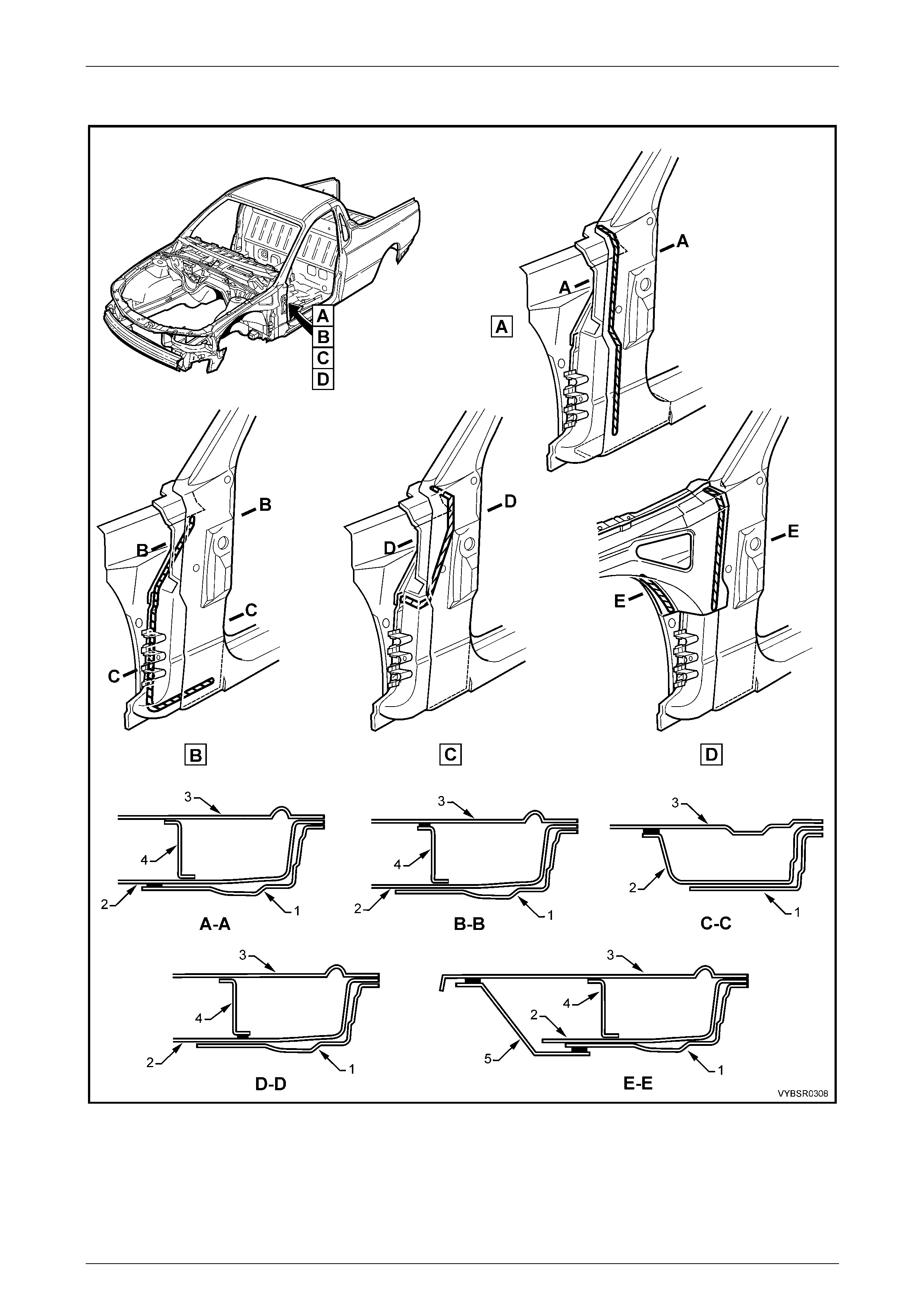
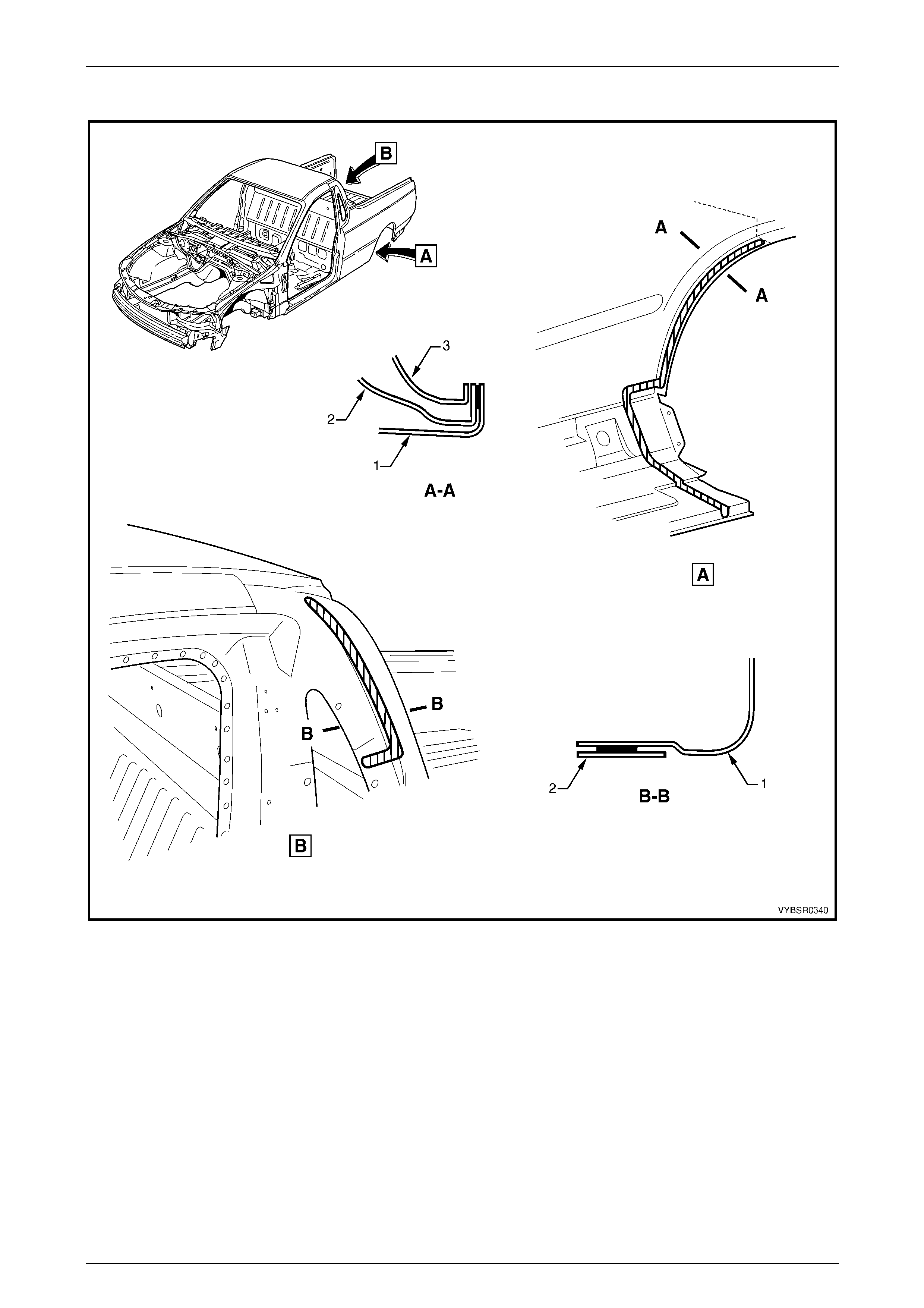
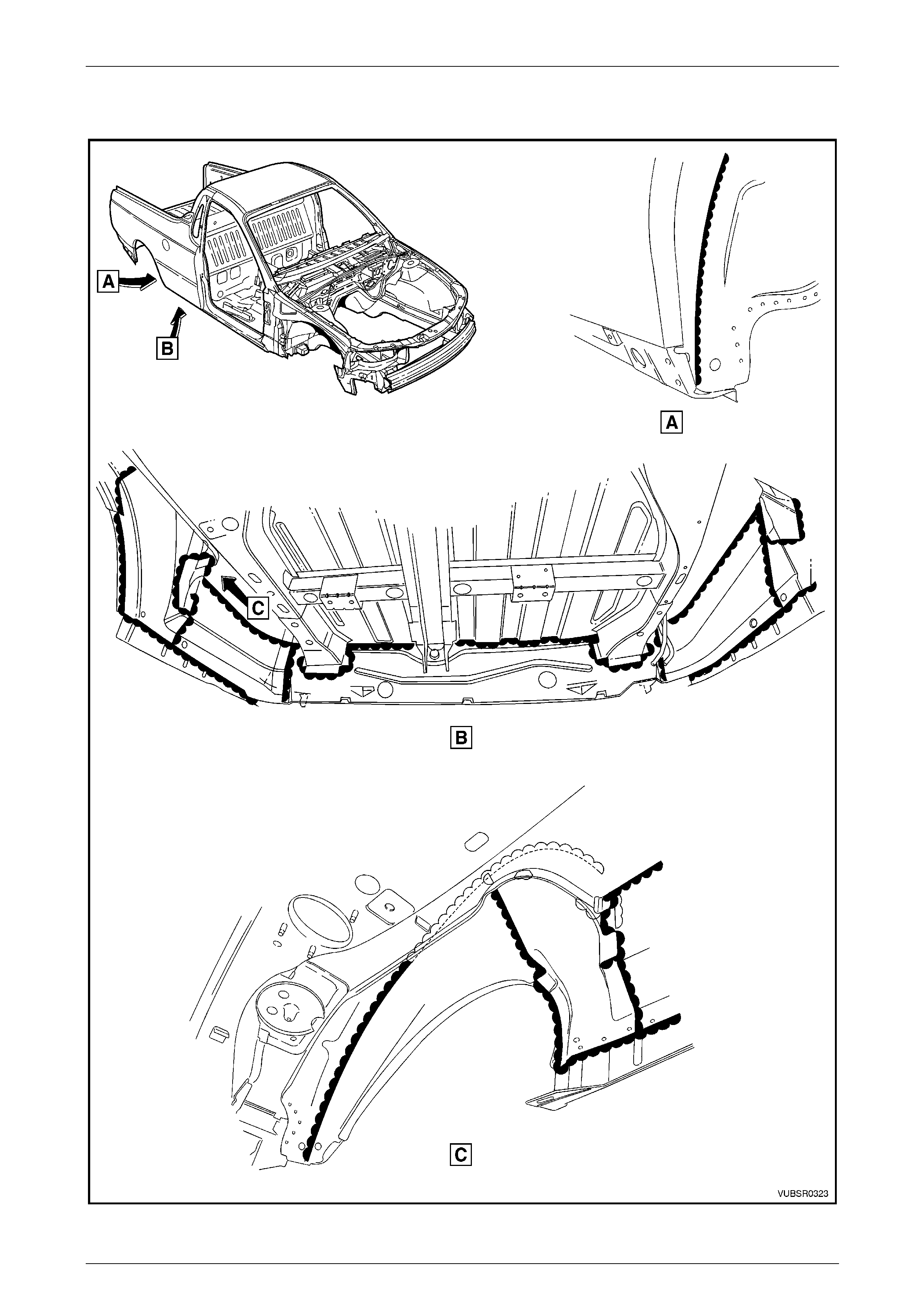
5.1 Acrylic Spot Weld Sealer (Item 2)
Figure 3C – 13
Legend
1 Door Opening Frame
2 Reinforcement – Hinge pillar
3 Hinge Pillar Inner Panel
4 Closing Plate – Hinge Pillar
5 Front Wheelhouse Panel Upper Side Rail
3C Body Construction – Utility Page 3C-23
Page 3C-23
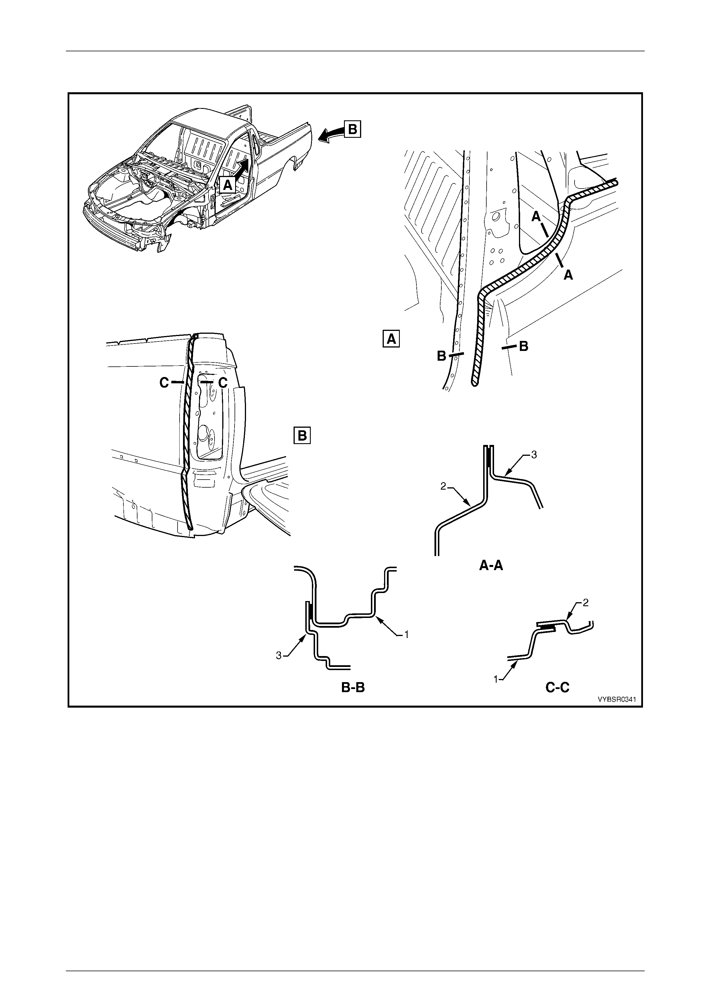
Acrylic Spot Weld Sealer (Item 2) Continued
Figure 3C – 14
Legend
Section A – A
1 Door Opening Frame Assembly
2 Reinforcement – Lock Pillar
3 Side Panel – Outer
Section B – B
1 Reinforcement – Lock Pillar
2 Side Panel – Outer Upper
3C Body Construction – Utility Page 3C-24
Page 3C-24
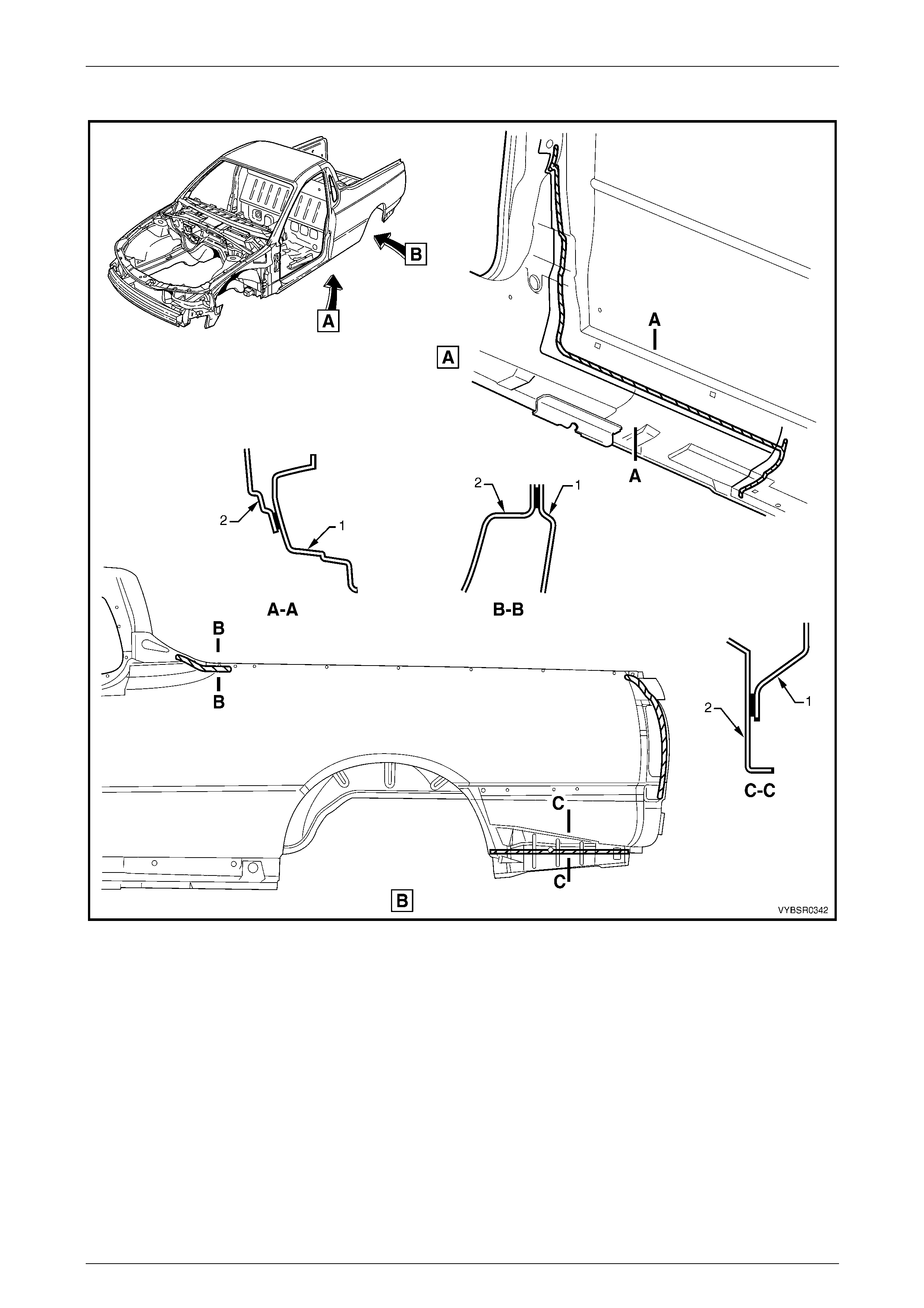
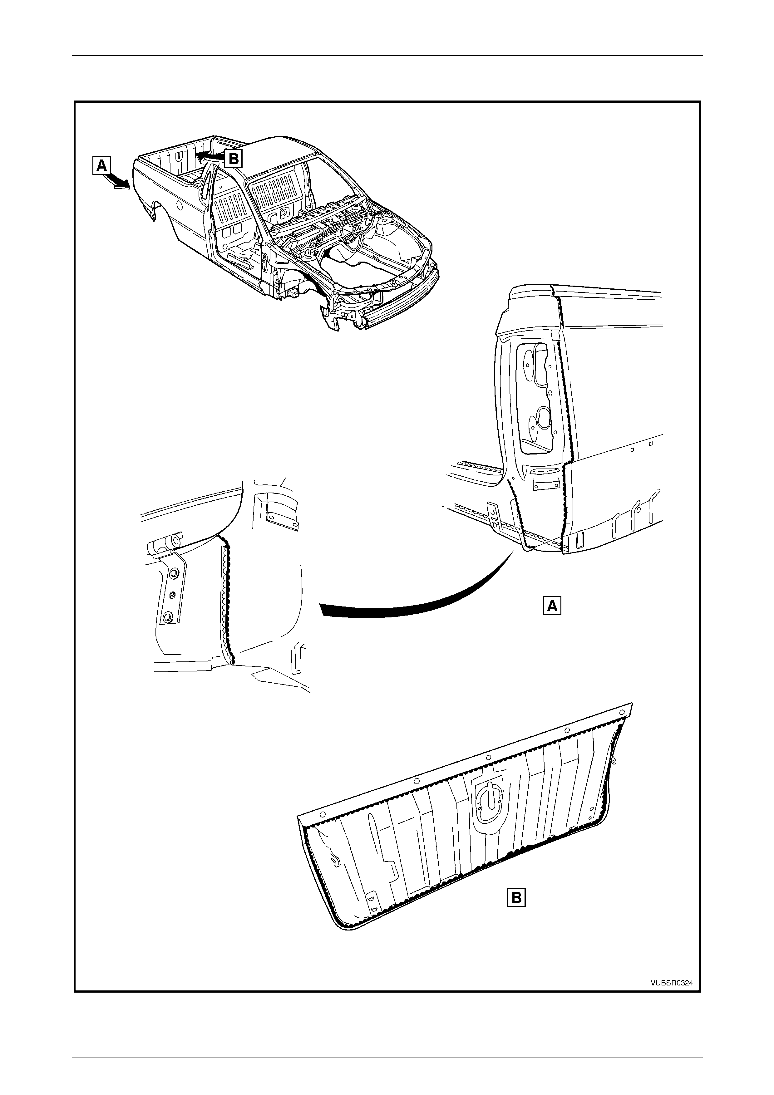
Acrylic Spot Weld Sealer (Item 2) Continued
Figure 3C – 15
Legend
Section A – A and B – B
1 Door Opening Frame Assembly
2 Reinforcement – Lock Pillar
3 Side Panel – Outer
Section C – C
1 Side Panel – Outer
2 Gusset Assembly – Tail Lamp
3C Body Construction – Utility Page 3C-25
Page 3C-25
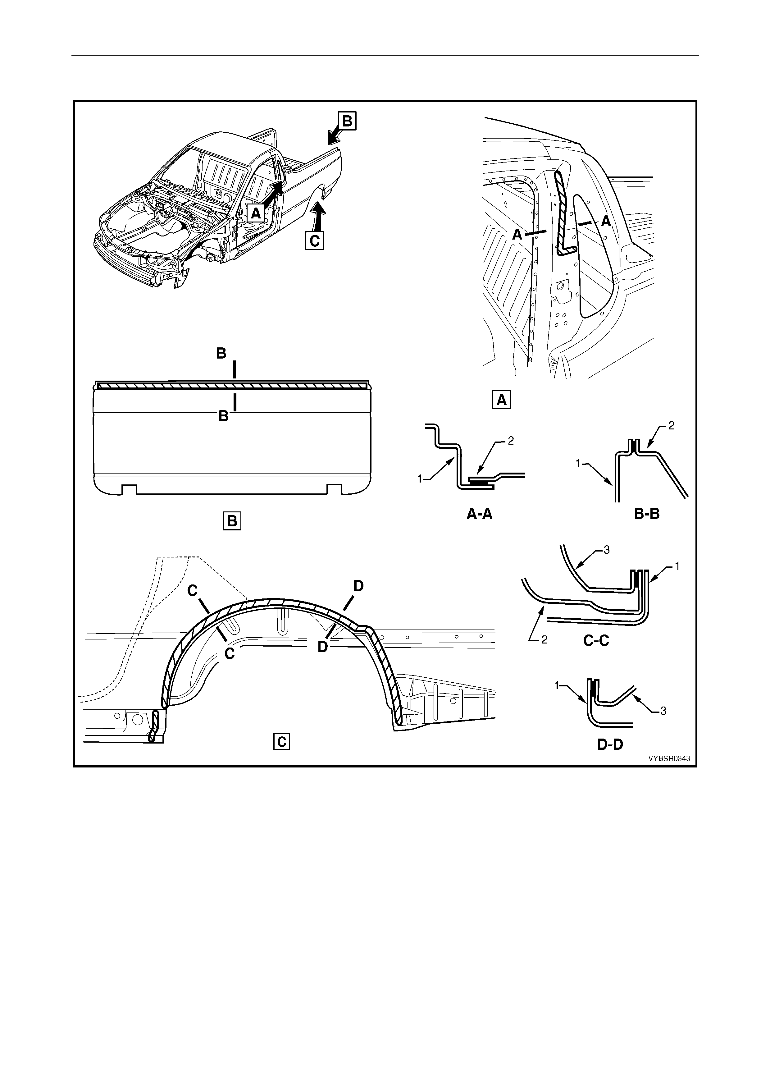
Acrylic Spot Weld Sealer (Item 2) Continued
Figure 3C – 16
Legend
Section A – A
1 Door Opening Frame Assembly
2 Side Panel – Outer
Section B – B and C – C
1 Side Panel – Inner
2 Side Panel – Outer
3C Body Construction – Utility Page 3C-26
Page 3C-26
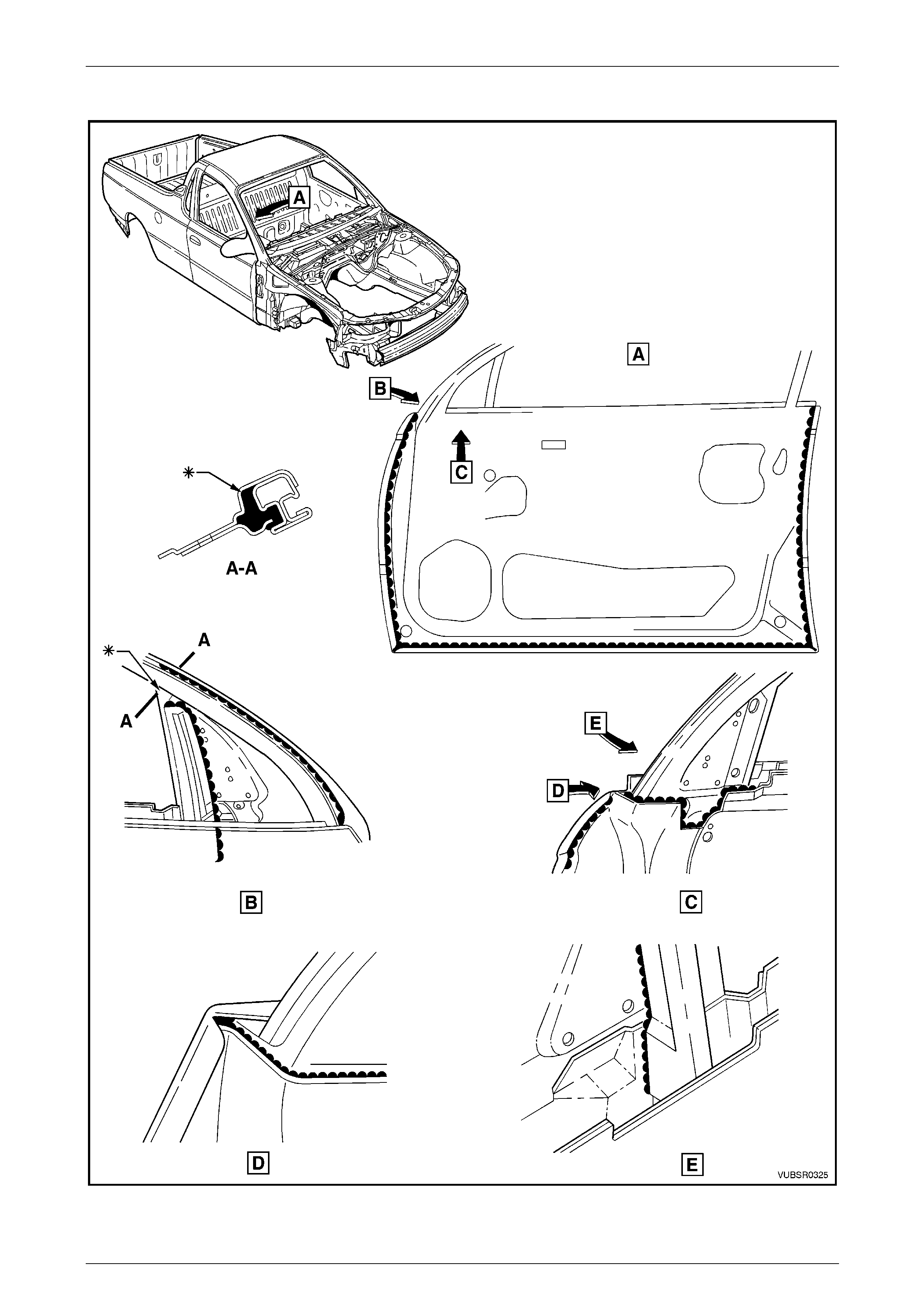
Acrylic Spot Weld Sealer (Item 2) Continued
Figure 3C – 17
Legend
Section A – A
1 Door Opening Frame Assembly
2 Side Panel – Outer
Section A – A
1 Endgate – Inner
2 Endgate – Outer
Section C – C and D – D
1 Side Panel – Outer
2 Door Opening Frame Assembly
3 Side Panel – Inner
3C Body Construction – Utility Page 3C-27
Page 3C-27
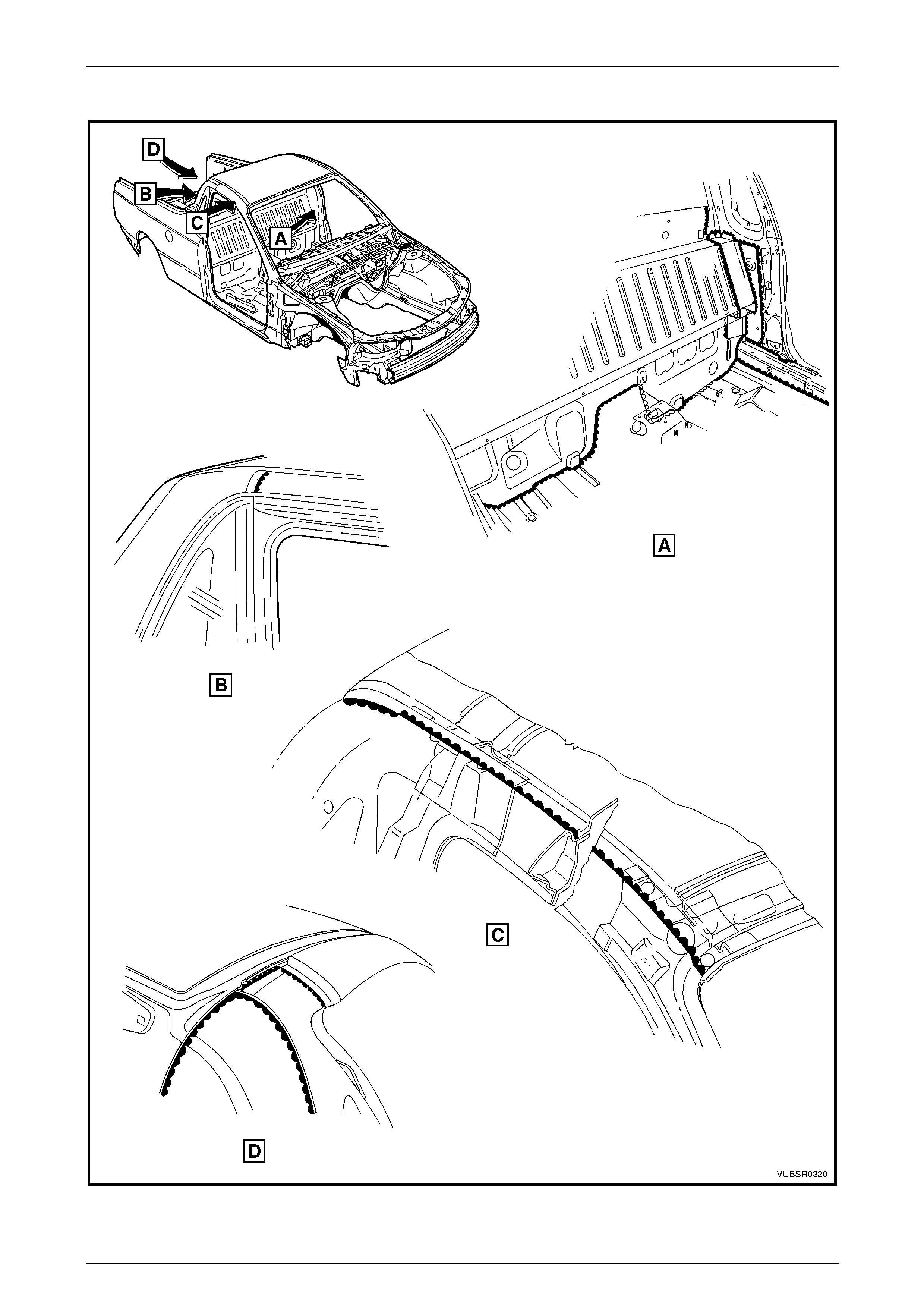
5.2 Joint Sealer (Item 3)
Figure 3C – 18
3C Body Construction – Utility Page 3C-28
Page 3C-28
Joint Sealer (Item 3) Continued
Figure 3C – 19
3C Body Construction – Utility Page 3C-29
Page 3C-29
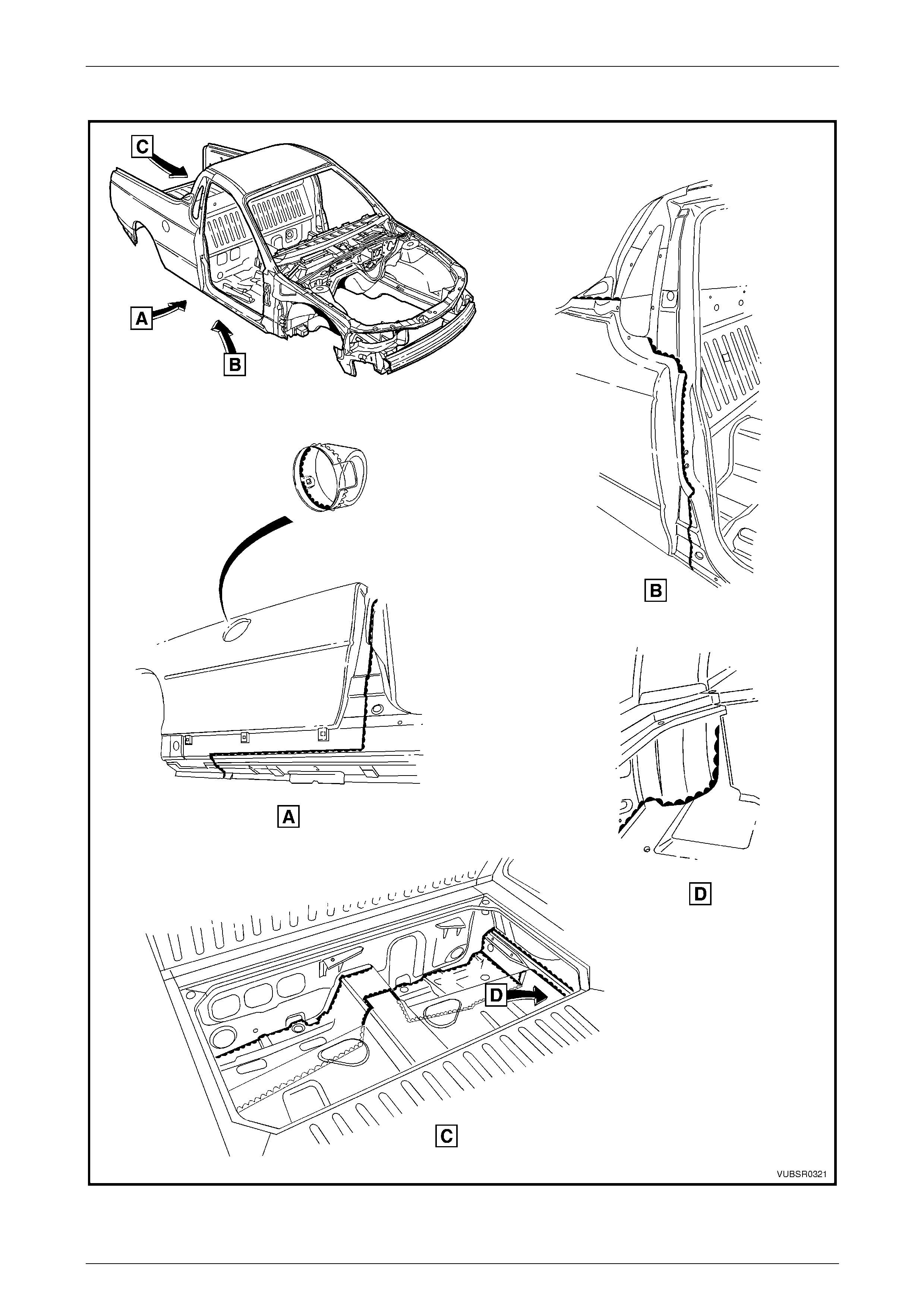
Joint Sealer (Item 3) Continued
Figure 3C – 20
3C Body Construction – Utility Page 3C-30
Page 3C-30
Joint Sealer (Item 3) Continued
Figure 3C – 21
3C Body Construction – Utility Page 3C-31
Page 3C-31
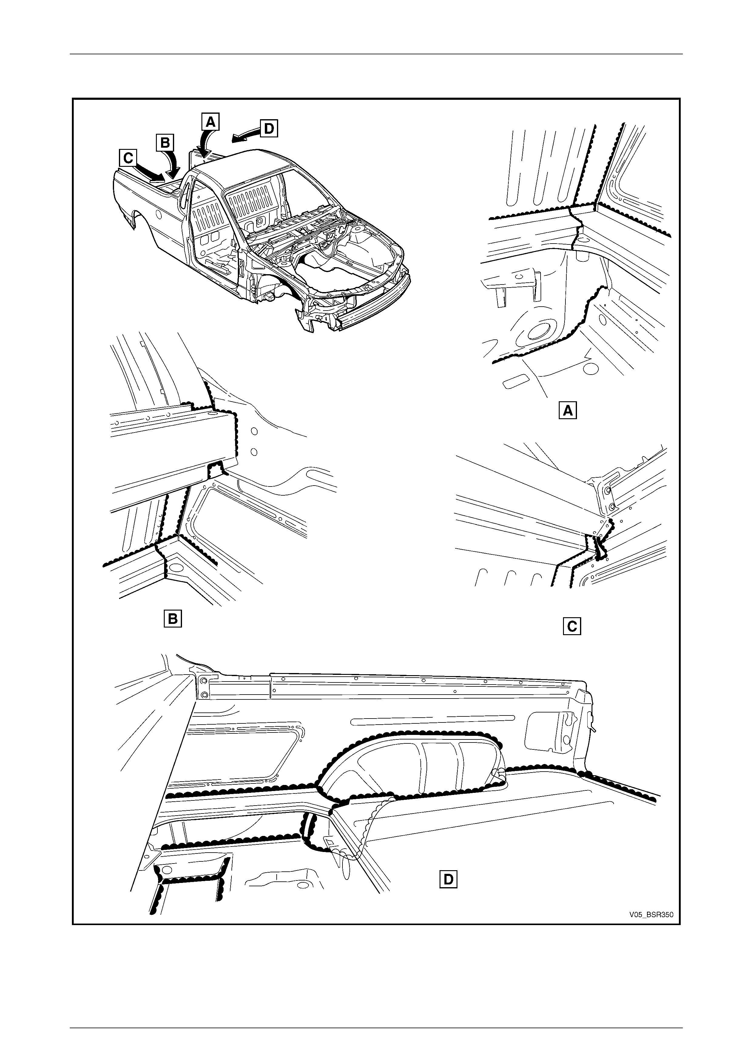
Joint Sealer (Item 3) Continued
Figure 3C – 22
3C Body Construction – Utility Page 3C-32
Page 3C-32
Joint Sealer (Item 3) Continued
Figure 3C – 23
3C Body Construction – Utility Page 3C-33
Page 3C-33
Joint Sealer (Item 3) Continued and Hand Putty (Item 4)
Figure 3C – 24
3C Body Construction – Utility Page 3C-34
Page 3C-34
5.3 Adhesive – Anti Flutter (Item 5)
Figure 3C – 25
3C Body Construction – Utility Page 3C-35
Page 3C-35
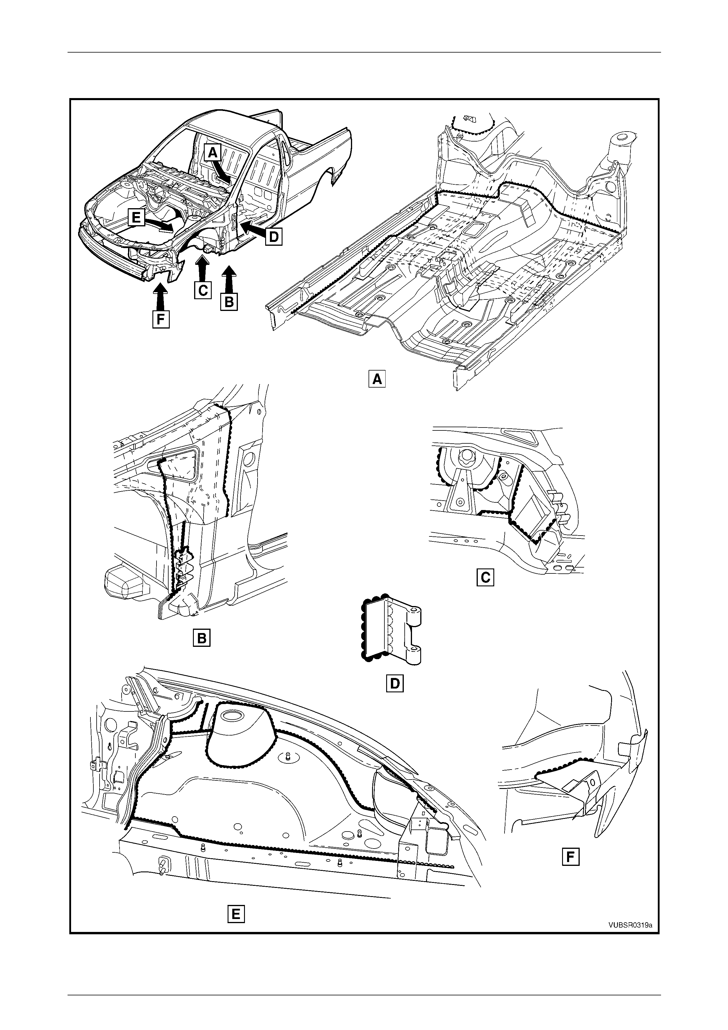
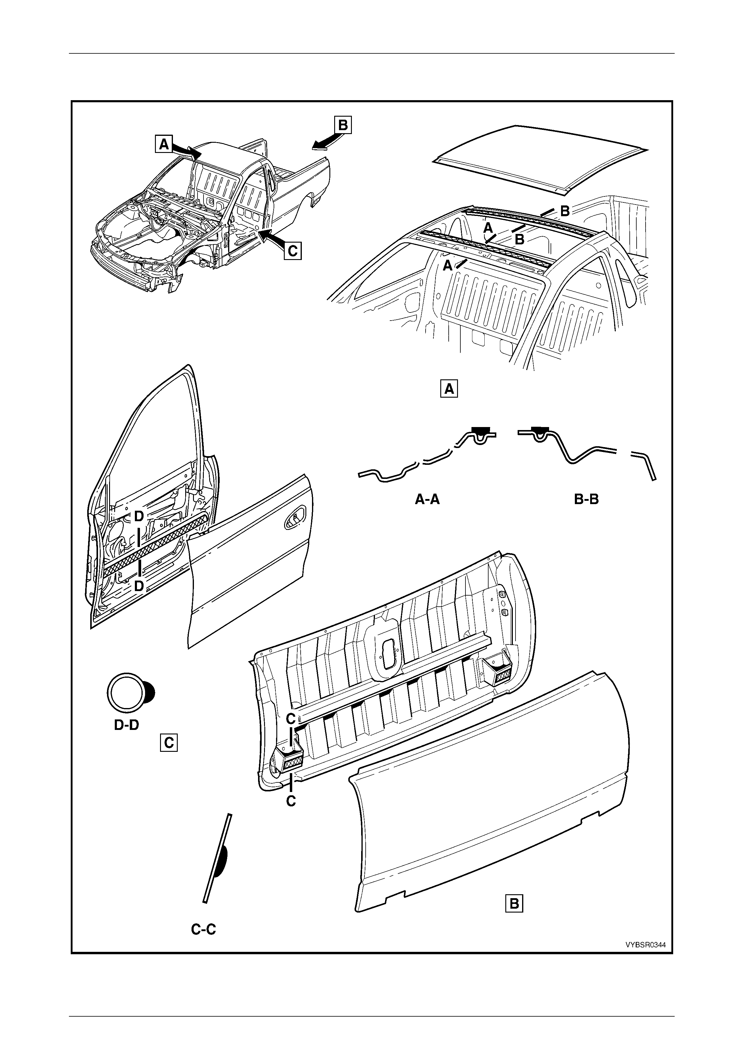
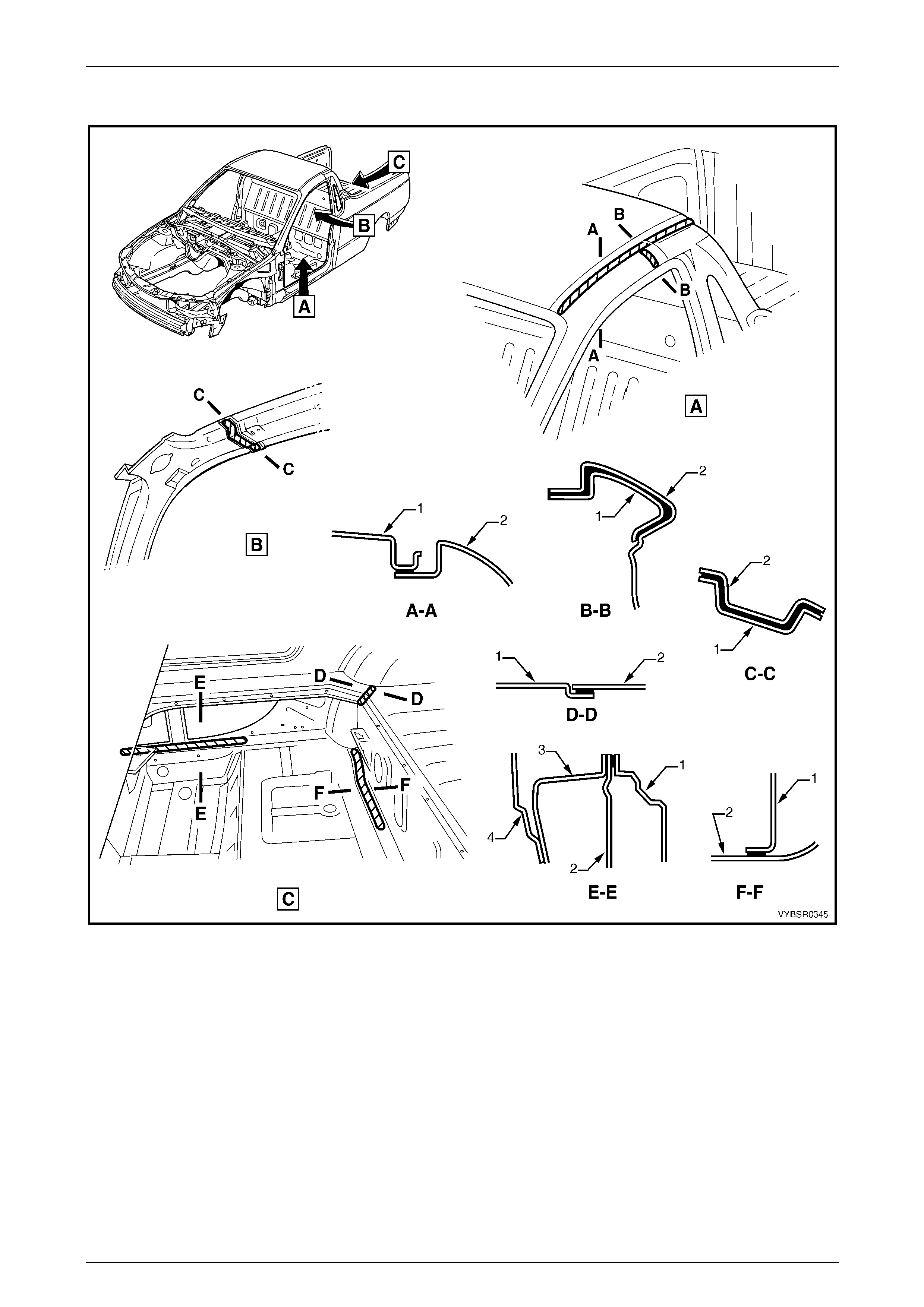
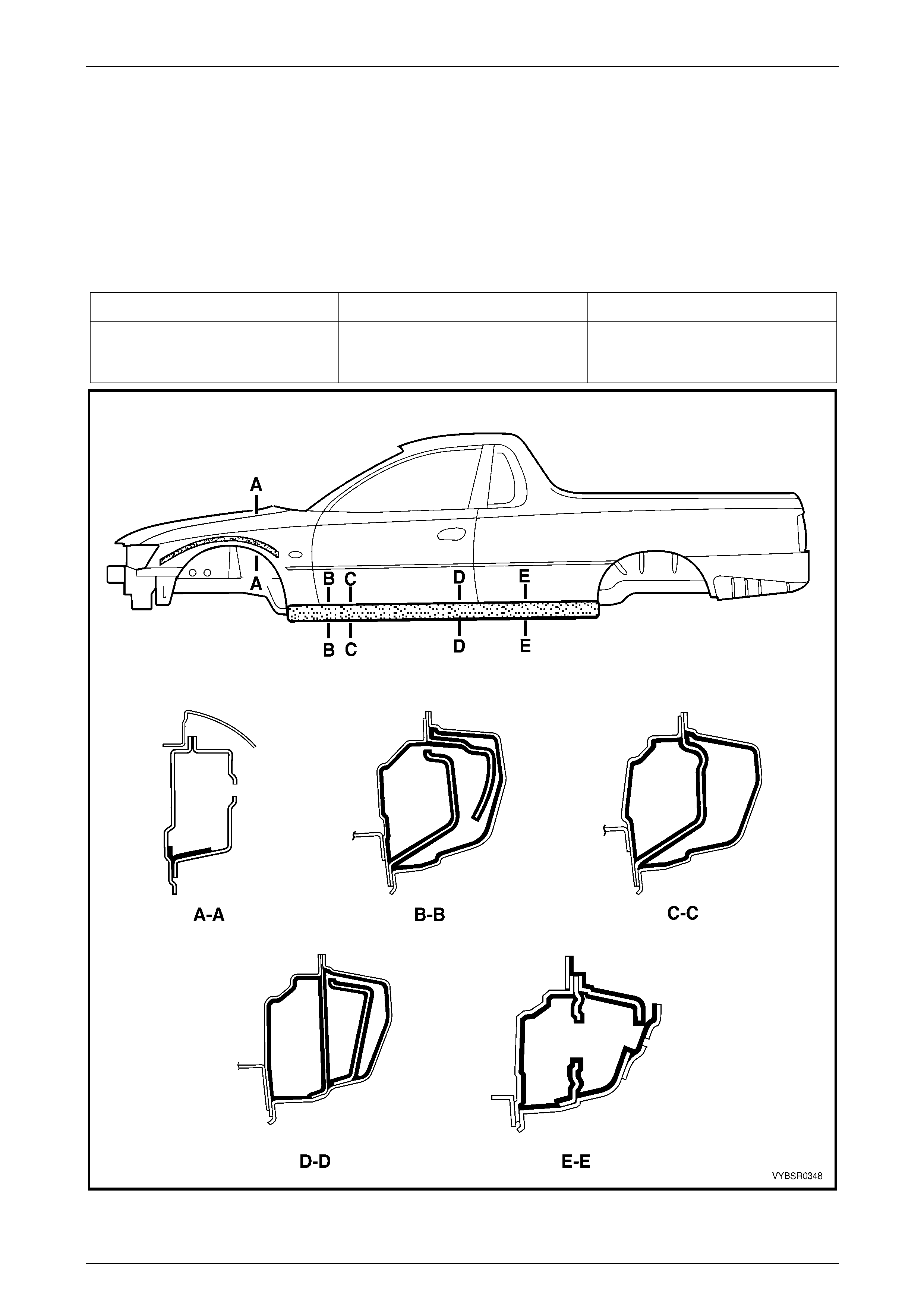
5.4 Adhesive – Structural (Item 6)
Figure 3C – 26
Legend
Section A – A
1 Roof Panel
2 Door Opening Frame Assembly
Section B – B
1 Side Panel – Outer Upper
2 Door Opening Frame Assembly
Section C – C
1 Frame – Side Front Roof
2 Hinge Pillar – Inner
Section D – D
1 Extension – Tonneau Floor Side
2 Floor – Tonneau Rear
Section E – E
1 Floor Side Panel
2 Side Panel – Inner
3 Door Opening Frame Assembly
4 Side Panel – Outer
Section F – F
1 Floor Assembly – Tonneau Rear
2 Rear Floor Assembly – Front

3C Body Construction – Utility Page 3C-36
Page 3C-36
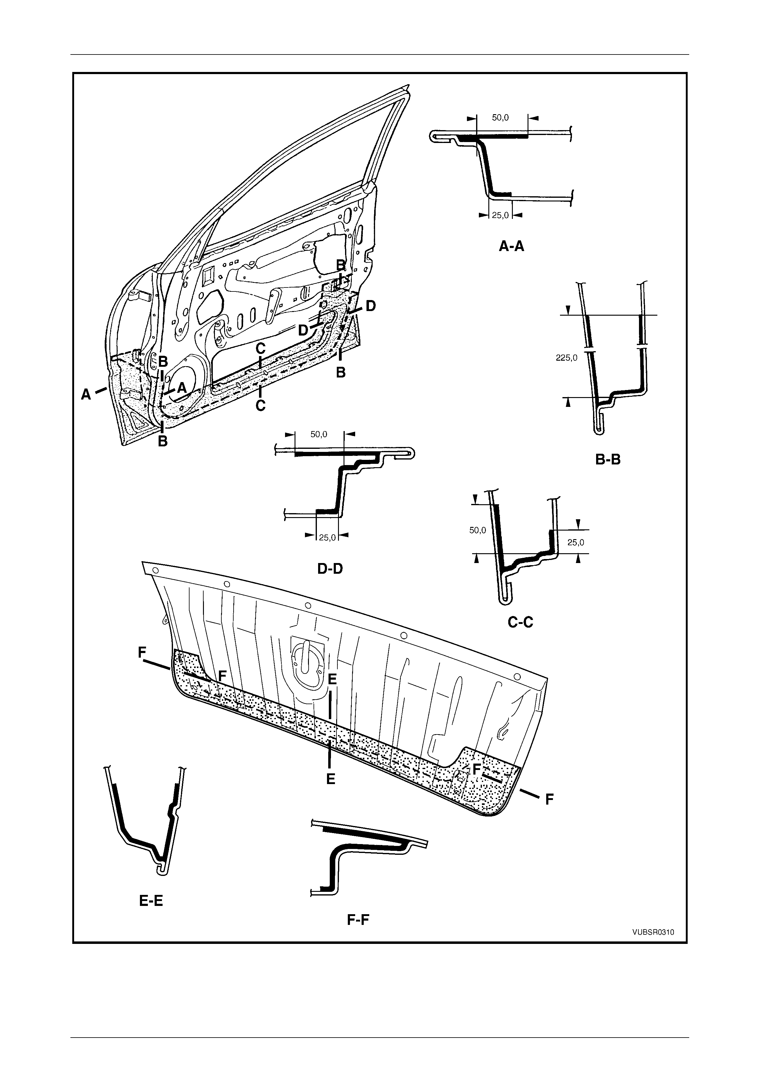
Figure 3C – 27
Legend
Section A – A
1 Door Panel – Inner
2 Door Panel – Outer
Section B – B
1 Wheelhouse – Inner
2 Rear Floor Assembly – Front
Section C – C
1 Endgate – Inner
2 Endgate – Outer
3C Body Construction – Utility Page 3C-37
Page 3C-37
5.5 Spray-on Deadener
Figure 3C – 28
3C Body Construction – Utility Page 3C-38
Page 3C-38
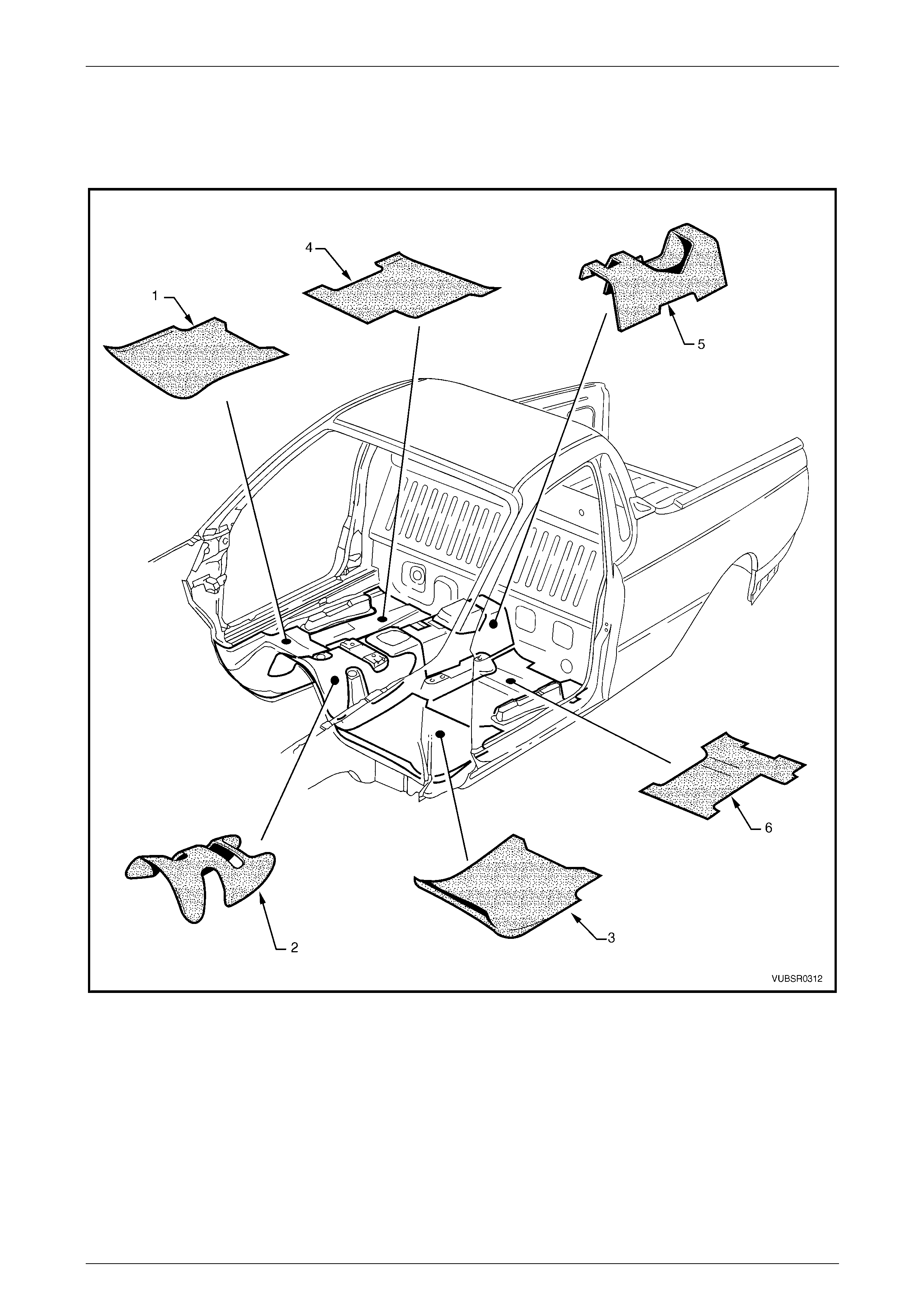
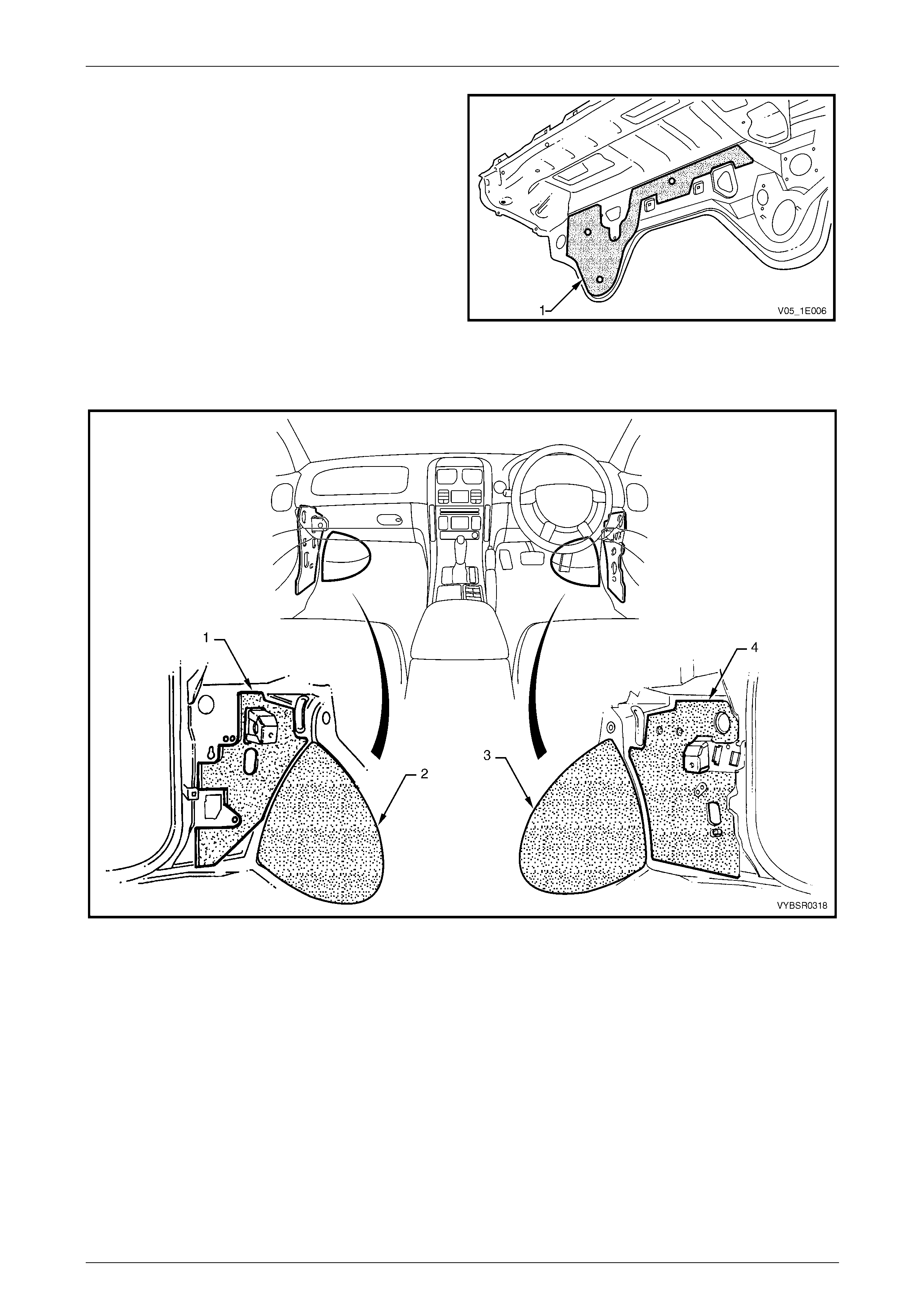
5.6 Deadener Panels and Insulators
The deadener panels shown are heat fusible type. They are to be installed with the di amond embossed side down. Use a
heat gun, heat lamps or such to cure each deadener sheet.
Figure 3C – 29
Legend
1 Deadener – Front Floor, Right-hand
2 Deadener – Front Floor, Centre
3 Deadener – Front Floor, Left-hand
4 Deadener – Rear Floor, Right-hand
5 Deadener – Rear Floor, Centre
6 Deadener – Rear Floor, Left-hand
3C Body Construction – Utility Page 3C-39
Page 3C-39
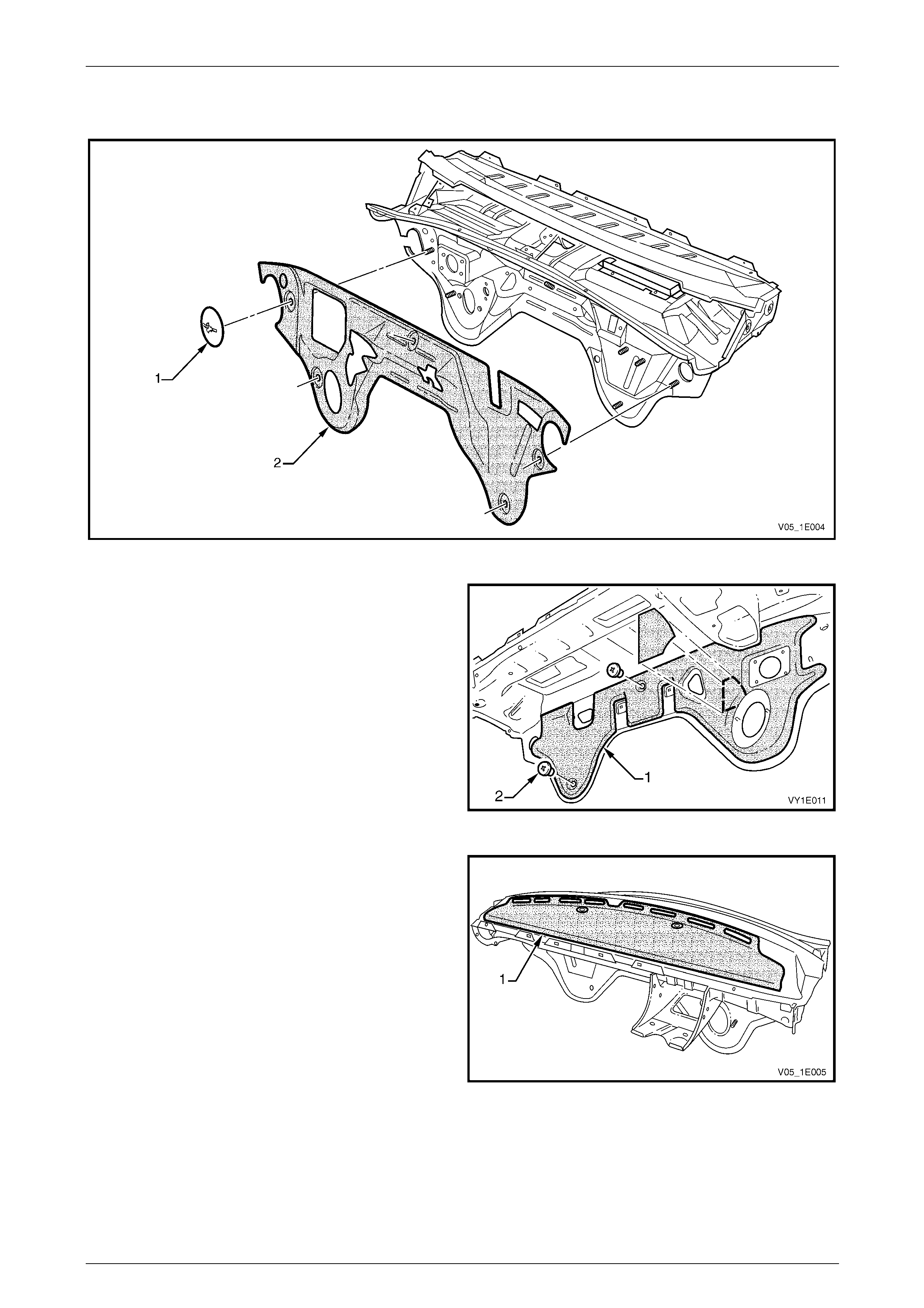
A retainer (1) is used at five places to attach the dash panel lower insulator outer (2) to the engine compartment side of
the dash panel, refer to Figure 3C – 30.
Figure 3C – 30
The dash panel lower insulator inner (1) is attached to the
dash panel with two retainers (2).
Figure 3C – 31
The dash panel upper insu lator (1) is adhered to the dash
panel and care is required during removal. If required, apply
contact adhesive to the insulator prior to affixing it to the
new dash panel and ensure it follows the form of the dash
panel.
If a new insulator is being fitted, remove the backing paper
prior to fitting and apply.
Figure 3C – 32
3C Body Construction – Utility Page 3C-40
Page 3C-40
The dash panel lower deadener (1) is a heat-fusible type.
Install it in position with the diamond embossed side to the
panel. Use a heat gun, heat lamps or such, to cure the
deadener. Smooth the deadener with a roller or such to
expel any air bubbles a nd to maximise adhesion.
Figure 3C – 33
The deadeners and insulators in Figure 3C – 34 are self adhesive. Remove the backing paper and attach the insulator
ensuring any cut-outs align with brackets etc. Smooth the insulator firmly into position.
Figure 3C – 34
Legend
1 Insulator – Cowl Side, Left-hand
2 Deadener – Front Floor Extension, Left-hand 3 Deadener – Front Floor Extension, Right-hand
4 Insulator – Cowl Side, Right-hand
3C Body Construction – Utility Page 3C-41
Page 3C-41
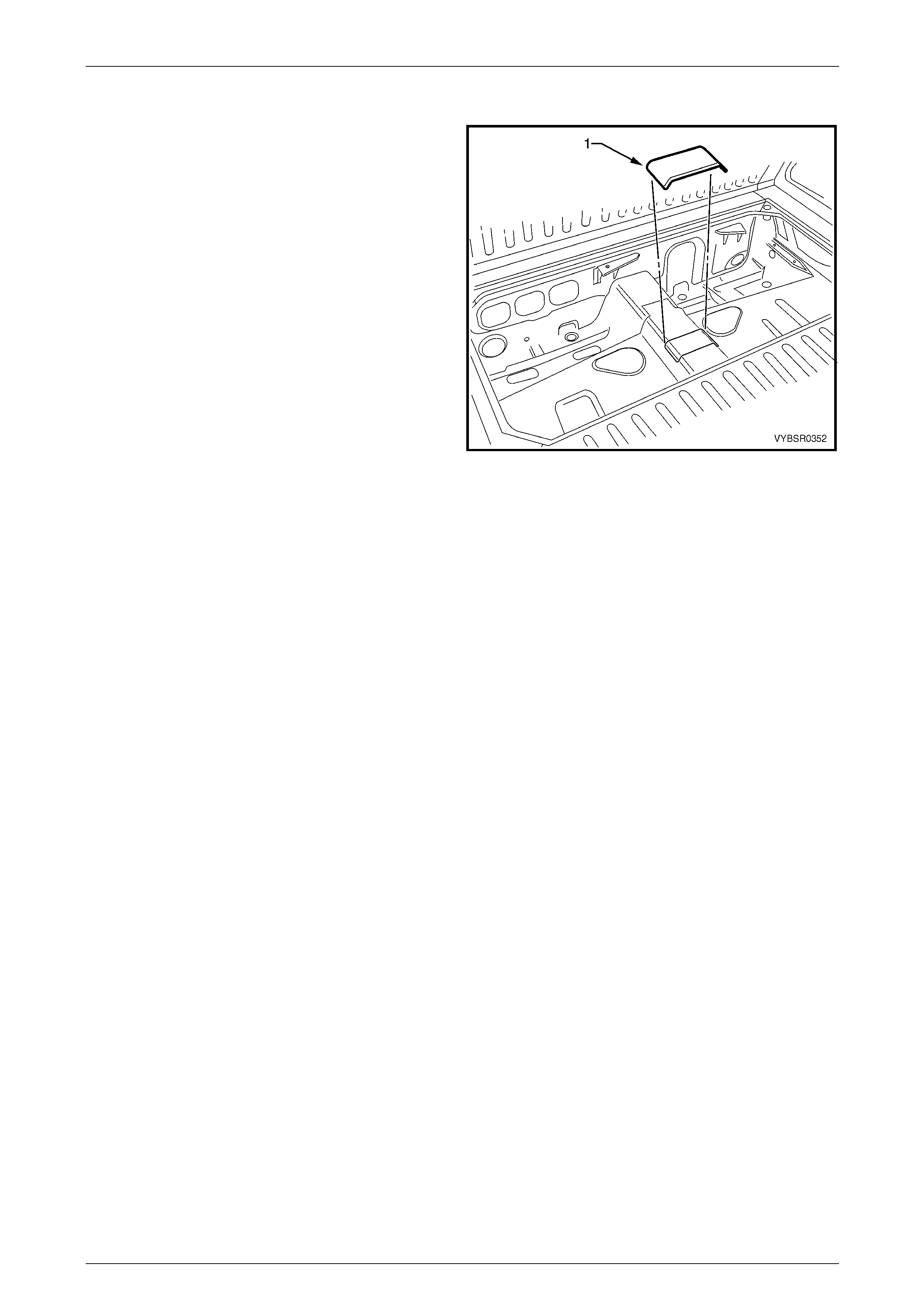
5.7 Fusible Reinforcement Patches
A heat fusible reinforcing patch (1) is applied to the floor
panel below the fuel tank which provi des stiffness and aids
in the reduction of Noise, Vibration and Harshness (NVH).
It is pliable in its uncured state and is applied to the vehicle
prior to paint baking. The heat required to cure and harden
the sheet is approximately 120 °C, and once cured the
sheet becomes a structural part of the vehicle. Therefore, if
the rear floor assembly is replaced, the patch must also be
replaced.
Lower curing temperature replacement patches are
available from an Authorised Dealer.
Replace
1 Where possible, apply th e patch to the new floor prior
to painting.
2 Ensure the surface is clean, dry and free from weld
spatter, etc.
3 Apply the patch (1) in the location shown.
4 Using a heat gun or dryi ng lamps, etc. evenly heat the
material until it smoothes and the edges begin to
‘soften’.
5 Smooth the material down with a roller or like, to
ensure no air bubbles are present and to maximise
adhesion.
6 Once cooled, the material should feel h ard.
Figure 3C – 35
3C Body Construction – Utility Page 3C-42
Page 3C-42
6 Cavity Wax
Utility body and structural panels ar e constructed from high qualit y corros ion res istant materials. Durin g manufacture,
cavity wax is applied to the ar eas shown to further increase the vehicle’s anti-corrosive properties.
Following repairs, to maintain the anti-corrosive properties of the vehicle, o nce the p aint is thoroughly dry apply cavity
wax to the areas shown below, and within any repaired box sect ions or areas inaccessible to paint. Refer to the table for
equivalent products to those used in manufacture.
Cavity Wax Equivalen ts
Item No. Equivalent Manufacturer Equivalent Product Name
8 Henkel
Terotex HV 8377/65
Nox Rust Hi-Wax 100B
Terasol 800113 (Aerosol pack)
Figure 3C – 36
3C Body Construction – Utility Page 3C-43
Page 3C-43
Figure 3C – 37