
3F Body Construction – Crew Cab Page 3F–1
Section 3F
Body Construction – Crew Cab
ATTENTION
Before performing any service operation or other procedure described in this Section, refer to Section 2
Precautions in this Supplement and Section 00 Warnings, Cautions and Notes in the MY2005 VZ Service
Information for correct workshop practices with regard to safety and/or property damage.
The structure of the body shell has been
developed using complex design and
development techniques. In addition to
meeting all required standards, the vehicle
body is also a critical part of the overall safety
systems. It is therefore imperative the repair
procedures described here are adhered to
during all vehicle body repairs.
1 General Information ...............................................................................................................................2
2 Body Structure Panels...........................................................................................................................3
2.1 Front End and Underbody..................................................................................................................................... 4
2.2 Upperbody Structure............................................................................................................................................. 6
2.3 Body Assembly...................................................................................................................................................... 8
2.4 Rear Tray Body Assembly .................................................................................................................................. 10
3 Body Dimensions.................................................................................................................................12
3.1 Underbody Dimensions – Projected .................................................................................................................. 12
3.2 Upperbody Dimensions – Actual........................................................................................................................ 15
Front...................................................................................................................................................................... 15
Side and Interior................................................................................................................................................... 16
Rear Body............................................................................................................................................................. 17
4 Body Margins........................................................................................................................................18
5 Body Sealing, Adhesives and Deade ners..........................................................................................20
5.1 Acrylic Spot Weld Sealer (Item 2)....................................................................................................................... 22
Acrylic Spot Weld Sealer (Item 2) Continued .................................................................................................... 23
Acrylic Spot Weld Sealer (Item 2) Continued .................................................................................................... 24
Acrylic Spot Weld Sealer (Item 2) Continued .................................................................................................... 25
5.2 Joint Sealer (Item 3)............................................................................................................................................. 26
Joint Sealer (Item 3) Continued.......................................................................................................................... 27
Joint Sealer (Item 3) Continued.......................................................................................................................... 28
Joint Sealer (Item 3) Continued.......................................................................................................................... 29
Joint Sealer (Item 3) Continued.......................................................................................................................... 30
Joint Sealer (Item 3) Continued and Hand Putty (Item 4) ................................................................................. 31
5.3 Adhesive – Anti-Flutter (Item 5).......................................................................................................................... 32
5.4 Adhesive – Structural (Item 6) ............................................................................................................................ 33
Adhesive – Structural (Item 6) Continued.......................................................................................................... 34
5.5 Spray-on Deaden er.............................................................................................................................................. 35
5.6 Deadeners and Insulators................................................................................................................................... 36
6 Cavity Wax ............................................................................................................................................39
Page 3F–1

3F Body Construction – Crew Cab Page 3F–2
1 General Information
This Section contains body construction information specific to Crew Cab vehicles. For body constructio n informati on
relevant to all models, refer to Section 3 Body Construction.
The various sealers and adhesives used throughout the body are also described as it is imperative that only the correct
materials are used for repairs.
The correct cavity wax, deadeners a nd paint refinishing techni ques are also imperative if the vehicle is to be returned to
its original condition. When re placing or repairing a part or sub-assembly, care must be ta ken to ensure that correct
alignment and strength of the unit as a whole is maintained. In some instances, major damage to the body or frame can
be repaired more effectively and economically by replac ing a part or sub-assembly with a new one, rather than repairing
the damaged part.
Page 3F–2

3F Body Construction – Crew Cab Page 3F–3
2 Body Structure Panels
The following tables and illustrations describe the body structure assemblies and panels that are ava ilable for service
replacement.
NOTE
Always refer to an Authorised Retailer for spare
parts availability configurations.
Page 3F–3
3F Body Construction – Crew Cab Page 3F–4
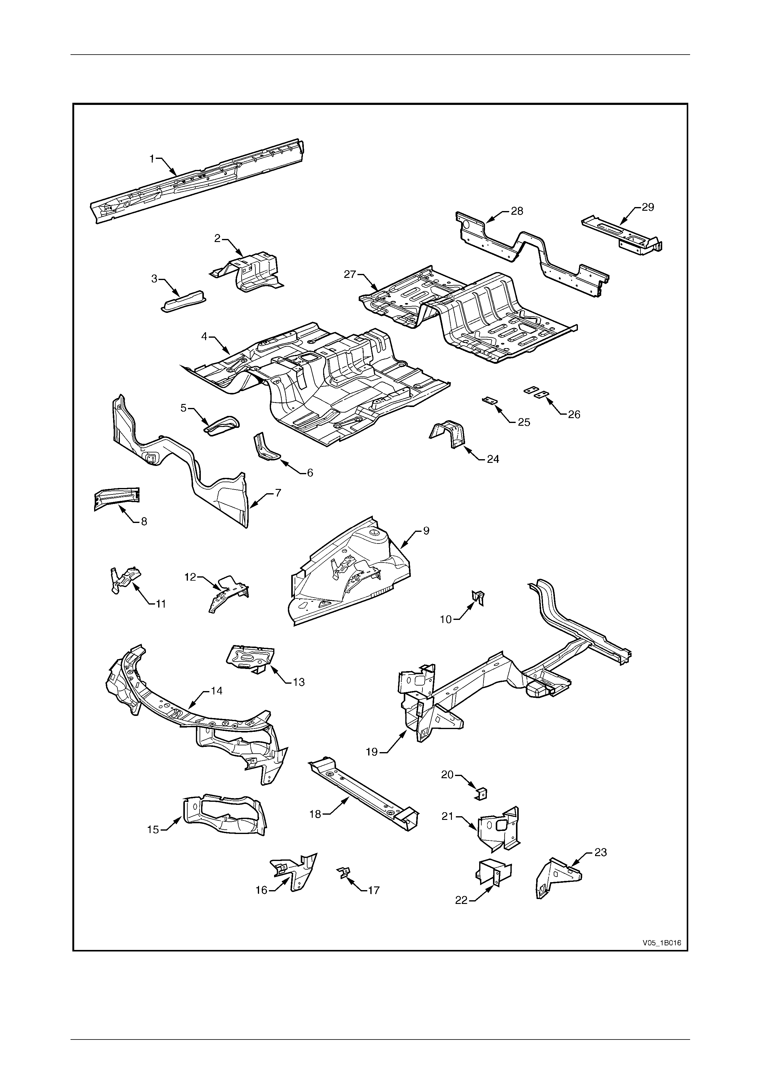
2.1 Front End and Underbody
Figure 3F – 1
Page 3F–4

3F Body Construction – Crew Cab Page 3F–5
Legend
1 Inner Rocker Panel Assembly, Right-hand / Left-hand
2 Seat Inner Bracket Assembly
3 Seat Outer Bracket Assembly, Right-hand / Left-hand
4 Front Floor Panel Assembly
5 Transmission Support Bracket, Right-hand / Left-hand*
6 Transmission Support Bracket, Left-hand (AWD only)
7 Front Floor Panel Extension
8 Front Side Rail Brace, Right-hand / Left-hand
9 Front Wheelhouse Panel Assembly, Right-hand / Left-hand
10 Horn Bracket Assembly, Left-hand only
11 Relay Housing Bracket, Right-hand only
12 ABS Modulator Bracket Assembly, Right-hand only
13 Battery Tray Assembly, Right-hand only
14 Front End Panel Assembly
15 Headlamp Panel, Left-hand / Right-hand
16 Headlamp and Front Fascia Mount Bracket, Left-hand /
Right-hand
17 Fender Front Lower Bracket, Left-hand / Right-hand
18 Radiator Lower Support Assembly
19 Front Side Rail Assembly, Left-hand / Right-hand
20 Radiator Side Mounting Bracket, Left-hand / Right-hand
21 Front Wheelhouse Bracket Assembly, Left-hand / Right-
hand
22 Front Bumper Impact Bar Bracket, Left-hand / Right-hand
23 Front Wheelhouse Panel Bracket, Left-hand / Right-hand
24 Propeller Shaft Hanger Assembly
25 Rear Seatbelt Anchor Plate Assembly (three places)
26 Floor Panel Plate Assembly (two places), Left-hand / Right-
hand
27 Front Floor Panel Extension Assembly
28 Rear Lower Body Panel
29 Rear Lower Body Panel Assembly, Left-hand/ Right-hand
* Right-hand side only for AWD vehicles
Page 3F–5
3F Body Construction – Crew Cab Page 3F–6
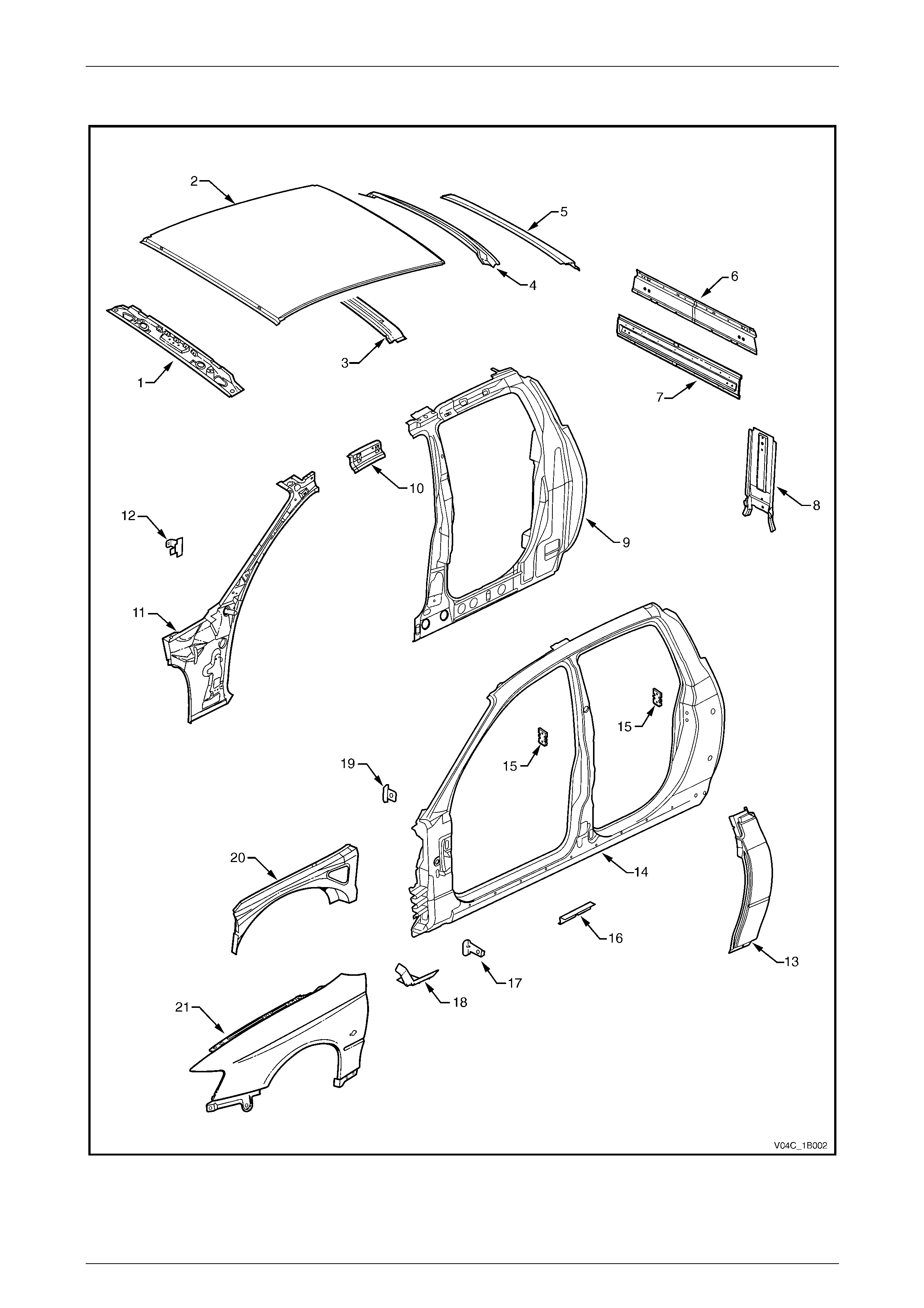
2.2 Upperbody Structure
Figure 3F – 2
Page 3F–6

3F Body Construction – Crew Cab Page 3F–7
Legend
1 Roof Front Header Panel
2 Roof Panel
3 Roof Bow Panel
4 Roof Rear Header Inner Panel
5 Roof Rear Header Outer Panel
6 Rear Body Upper Outer Panel Assembly
7 Rear Body Upper Inner Panel Assembly
8 Rear Body Lower Panel Assembly
9 Quarter Panel Inner Assembly, Right-hand / Left-hand
10 Quarter Panel Inner Extension, Right-hand / Left-hand
11 Hinge Pillar Inner Panel Assembly, Right-hand / Left-hand
12 Hinge Pillar Trim Panel Bracket, Right-hand / Left-hand
13 Rear Quarter Panel, Right-hand / Left-hand
14 Door Opening Frame Assembly, Right-hand / Left-hand
15 Door Striker Anchor Plate, Right-hand / Left-hand
16 Underbody Jacking Locator, Right-hand / Left-hand
17 Fender Rear Bracket, Right-hand / Left-hand
18 Fender Lower Rear Bracket, Right-hand / Left-hand
19 Fender Upper Rear Bracket, Right-hand / Left-hand
20 Front Wheelhouse Panel Upper Side Rail, Right-hand / Left-
hand
21 Front Fender, Right-hand / Left-hand*
* The front fender for AWD vehicles is supplied with holes for the front wheelhouse opening flare.
Page 3F–7
3F Body Construction – Crew Cab Page 3F–8
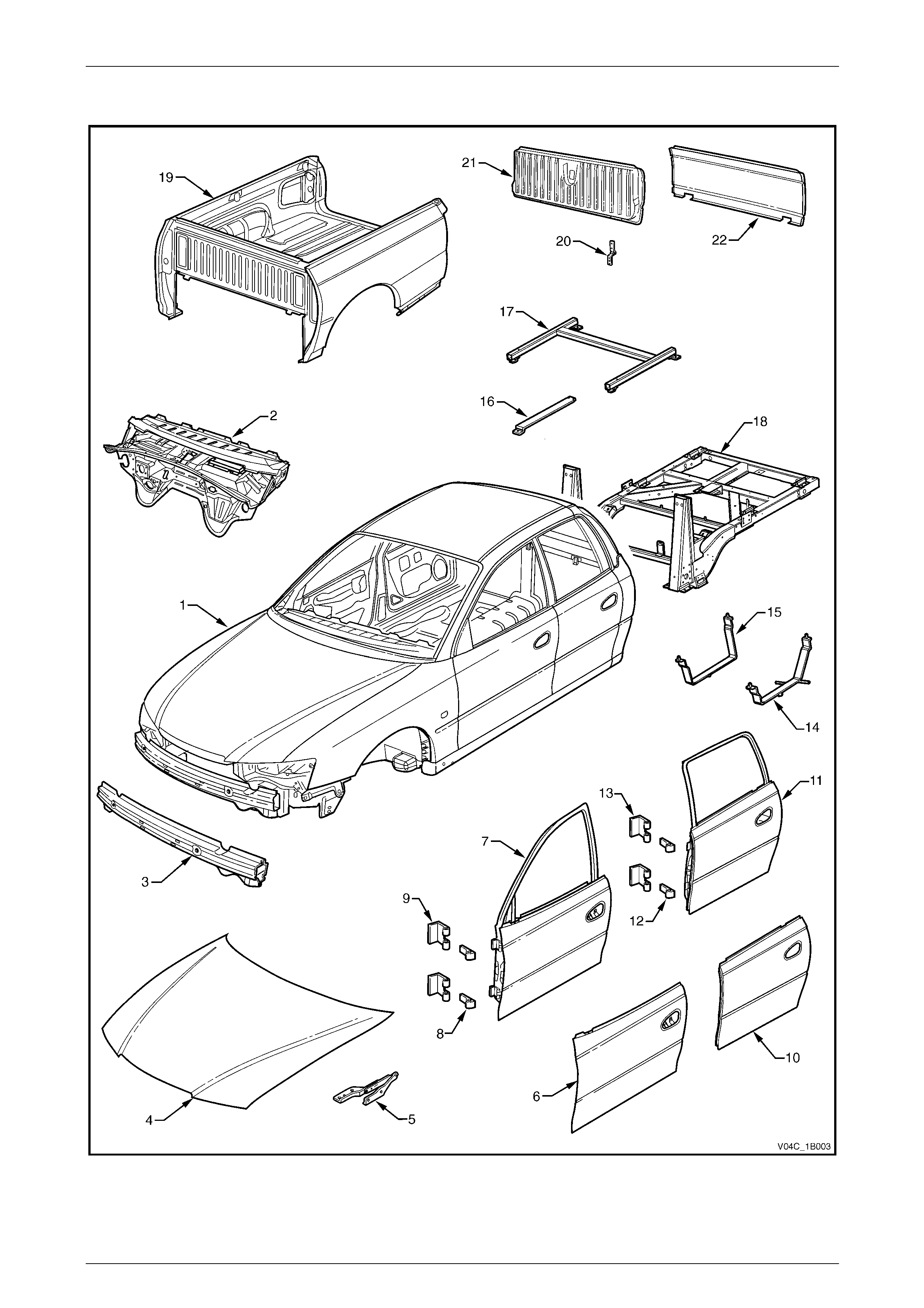
2.3 Body Assembly
Figure 3F – 3
Page 3F–8

3F Body Construction – Crew Cab Page 3F–9
Legend
1 Body Assembly
2 Dash Panel Assembly
3 Front Bumper Impact Bar Assembly
4 Hood Assembly
5 Hood Hinge Assembly, Right-hand / Left-hand
6 Front Door Outer Panel, Right-hand / Left-hand
7 Front Door Assembly, Right-hand / Left-hand
8 Front Door Hinge (door side), Right-hand / Left-hand
9 Front Door Hinge (body side), Right-hand / Left-hand
10 Rear Door Outer Panel, Right-hand / Left-hand
11 Rear Door Assembly, Right-hand / Left-hand
12 Rear Door Hinge (door side), Right-hand / Left-hand
13 Rear Door Hinge (body side), Righ t-hand / Left-hand
14 Fuel Tank Lower Strap, Left-hand
15 Fuel Tank Lower Strap, Right-hand
16 Fuel Tank Upper Strap, Left-hand/ Right-hand
17 Floor Support Frame
18 Subframe Assembly
19 Rear Tray Body Assembly
20 Endgate Hinge Assembly, Right-hand / Left-hand
21 Endgate Assembly
22 Endgate Outer Panel
Page 3F–9
3F Body Construction – Crew Cab Page 3F–10
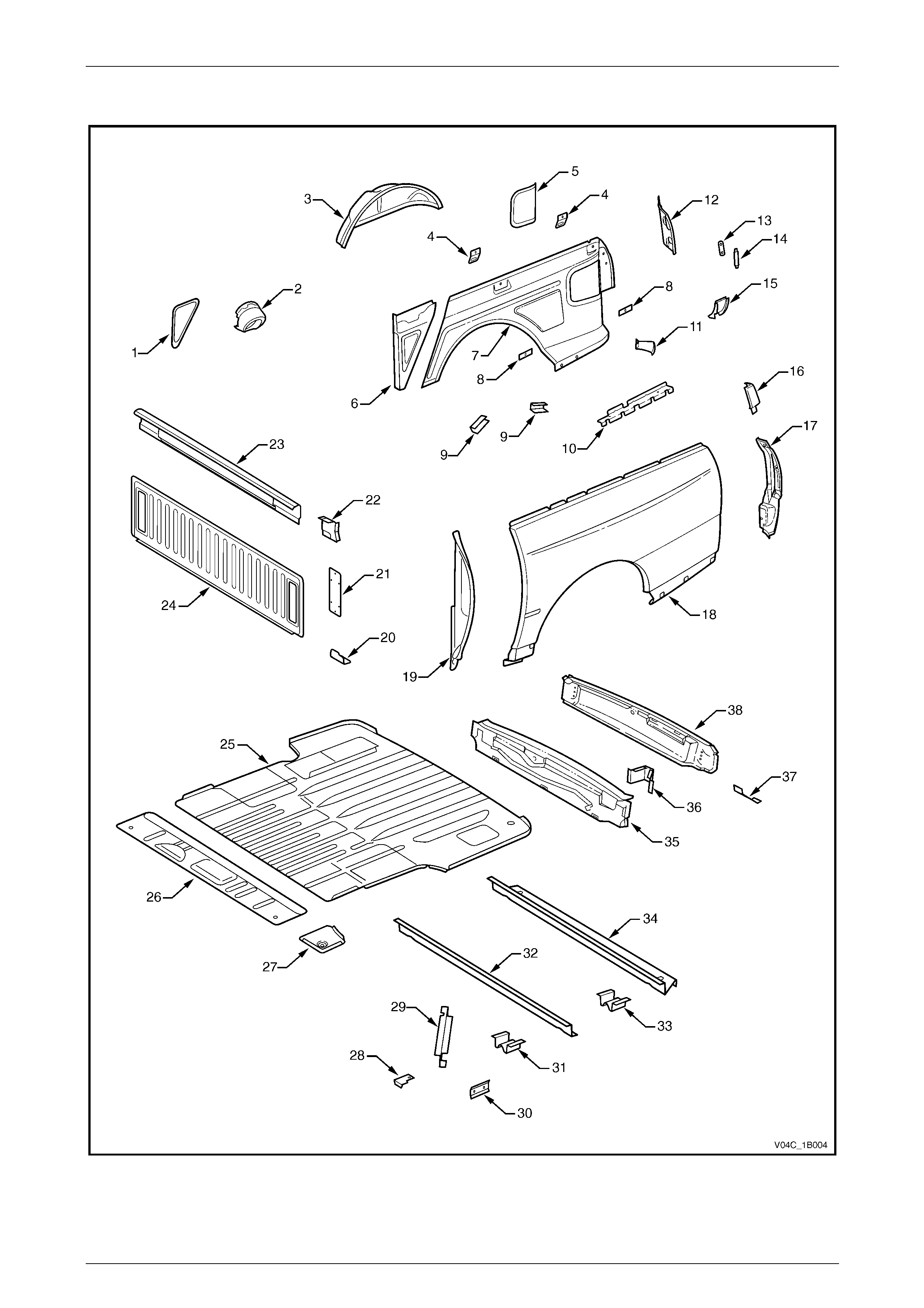
2.4 Rear Tray Body Assembly
Figure 3F – 4
Page 3F–10

3F Body Construction – Crew Cab Page 3F–11
Legend
1 Inner Side Panel Extension Cover, Right-hand only
2 Fuel Filler Pipe Housing, Right-hand only
3 Rear Wheelhouse Inner Panel, Left-hand / Right-hand
4 Cargo Tie Down Bracket (two places), Left-hand / Right-hand
5 Rear Inner Side Panel Cover, Left-hand / Right-hand
6 Inner Side Panel Extension Assembly, Left-hand / Right-hand
7 Inner Side Panel, Left-hand / Right-hand
8 Cargo Tie Down Anchor Plate Assembly (two places),
Left-hand / Right-hand
9 Wheelhouse Filler Panel Bracket (two places), Left-hand /
Right-hand
10 Rear Quarter Closing Panel, Left- hand / Right-hand
11 Quarter Panel Rear Brace, Left-hand / Right-hand
12 Quarter Inner Lower Rea r Extension, Left-hand / Right-hand
13 Endgate Striker Anchor Plate, Left-hand / Right-hand
14 Endgate Striker Anchor Plate Retainer, Left-hand / Right-hand
15 Quarter Lower Rear Panel, Left-hand / Right-hand
16 Quarter Panel Upper Extension, Left-hand / Right-hand
17 Quarter Panel Extension, Left-hand / Right-hand
18 Rear Quarter Panel, Left-hand / Right-hand*
19 Quarter Panel Front Gusset, Left-hand / Right-hand
20 Rear Body Front Bracket, Left-hand / Right-hand
21 Front End Panel Cover, Left-hand / Right-hand
22 Front Cover Attachment Beam, Left-hand / Right-hand
23 Front End Panel Sill Assembly
24 Front End Panel
25 Load Floor Panel
26 Load Floor Front Extension
27 Load Floor Panel Front Extension, Left-hand / Right-
hand
28 Front End Panel Locator, Left-hand / Right-hand
29 Load Floor Panel Support, Left-hand / Right-hand
30 Load Floor Panel Side Support, Left-hand / Right-hand
31 Load Floor Panel Locator, Left-hand / Right-hand
32 Load Floor Panel Front Support
33 Load Floor Panel Locator Guide, Left-hand / Right-hand
34 Load Floor Panel Rear Support
35 Rear End Panel
36 Endgate Hinge Reinforcement, Left-hand / Right-hand
37 Rear Fascia Centre Bracket, Left-hand / Right-hand
38 Rear End Lower Panel
* The rear quarter panel for AWD vehicles is supplied with holes for the rear wheelhouse opening flare.
Page 3F–11

3F Body Construction – Crew Cab Page 3F–12
3 Body Dimensions
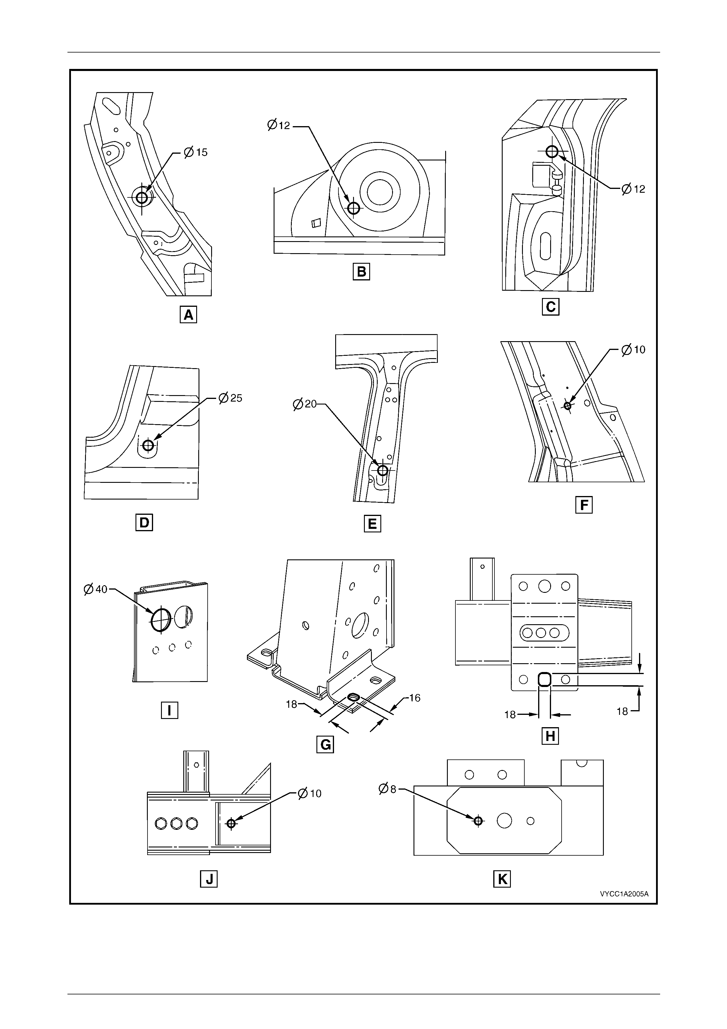
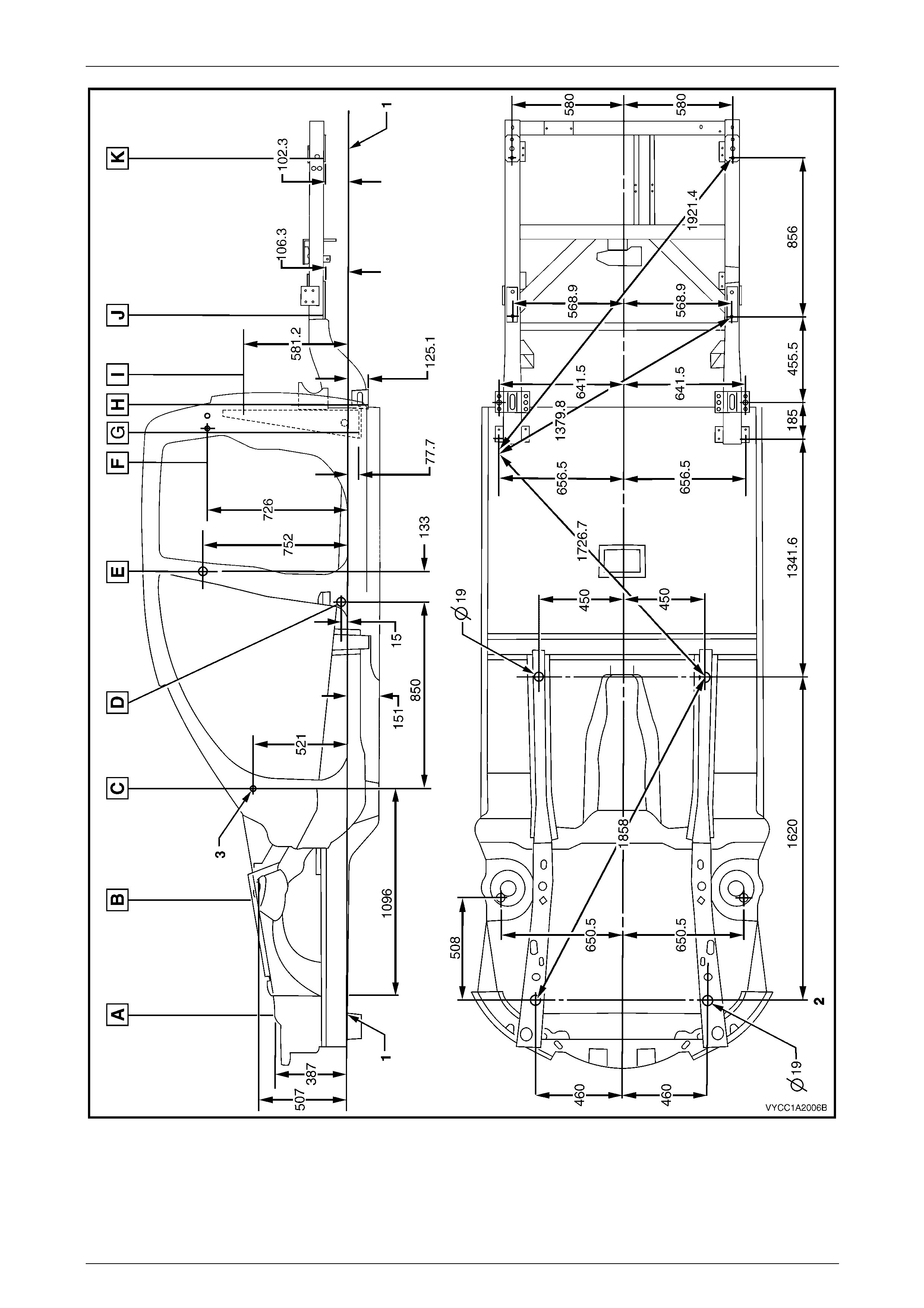
3.1 Underbody Dimensions – Projected
All dimensions are given in mm and are measured from the centre of holes, on the outer side of the metal surface.
The main datum surface (1) is the underside of the front side rail assembl y, refer to Figure 3F – 6.
The main datum hole (2) is a 19 mm hole on the underside of the front side rail assembly, refer to Figure 3F – 6.
The dash panel assembly attaching hole (3) in Figure 3F – 6 is also the same datum hole depicted at Vie w C in
Figure 3F – 5.
Page 3F–12
3F Body Construction – Crew Cab Page 3F–13
Figure 3F – 5
Page 3F–13
3F Body Construction – Crew Cab Page 3F–14
Figure 3F – 6
Page 3F–14
3F Body Construction – Crew Cab Page 3F–15
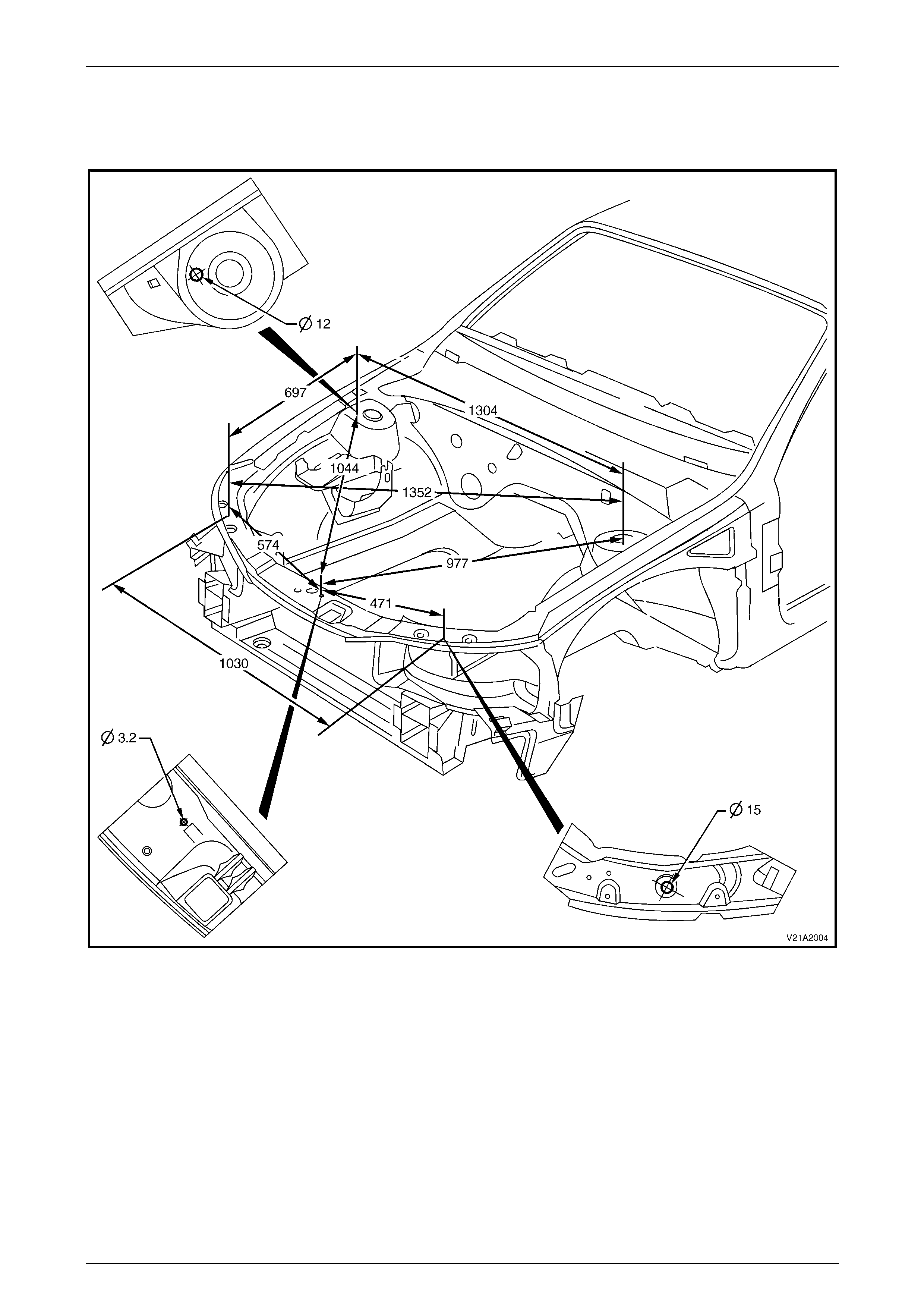
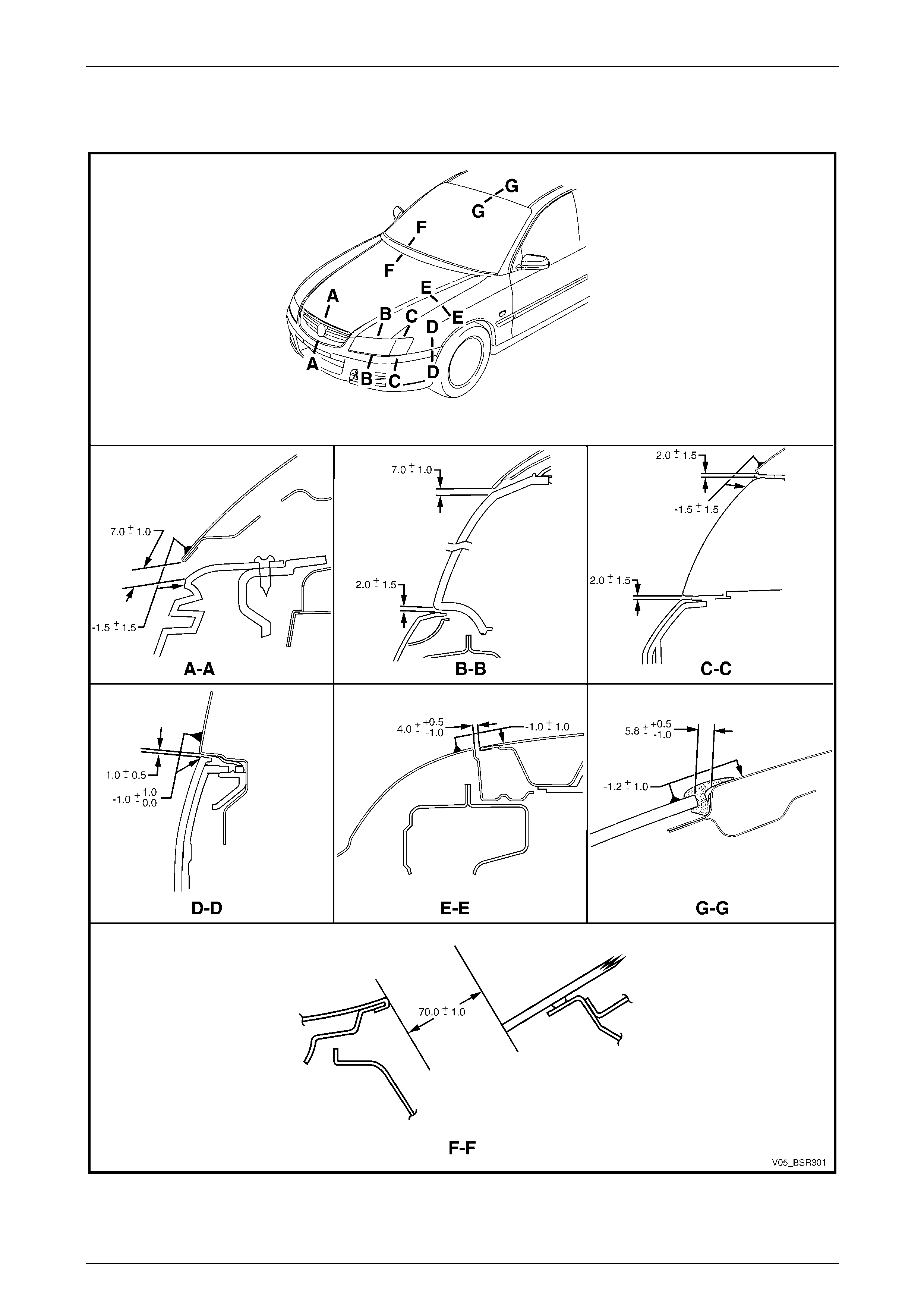
3.2 Upperbody Dimensions – Actual
Front
Figure 3F – 7
Page 3F–15
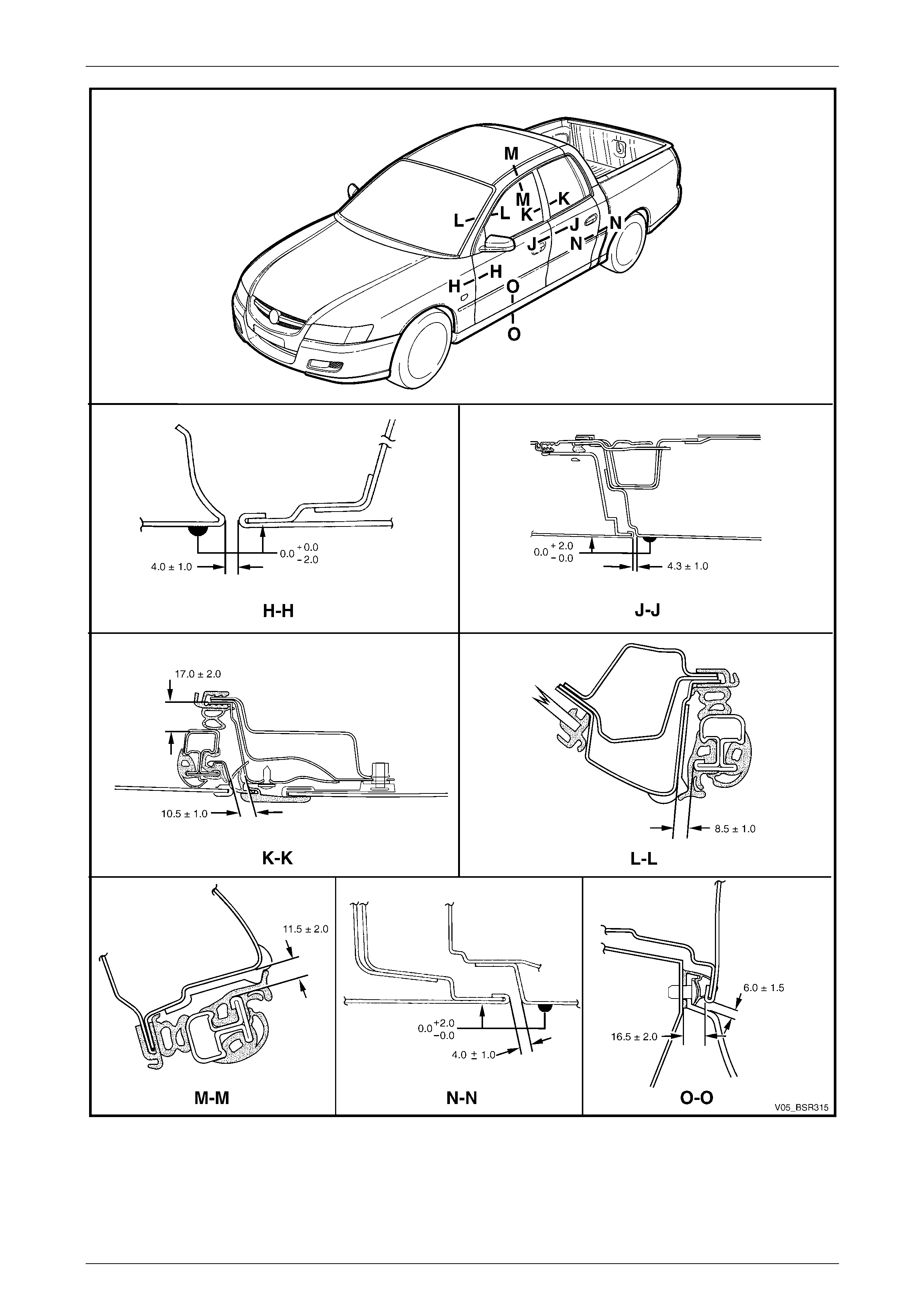
3F Body Construction – Crew Cab Page 3F–16
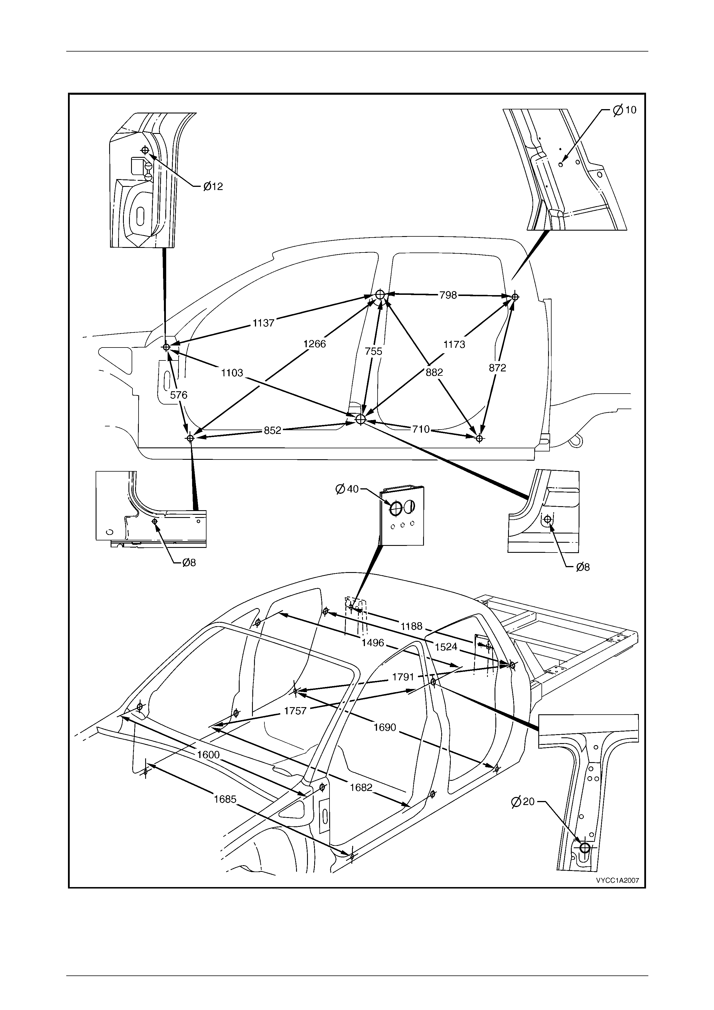
Side and Interior
Figure 3F – 8
Page 3F–16
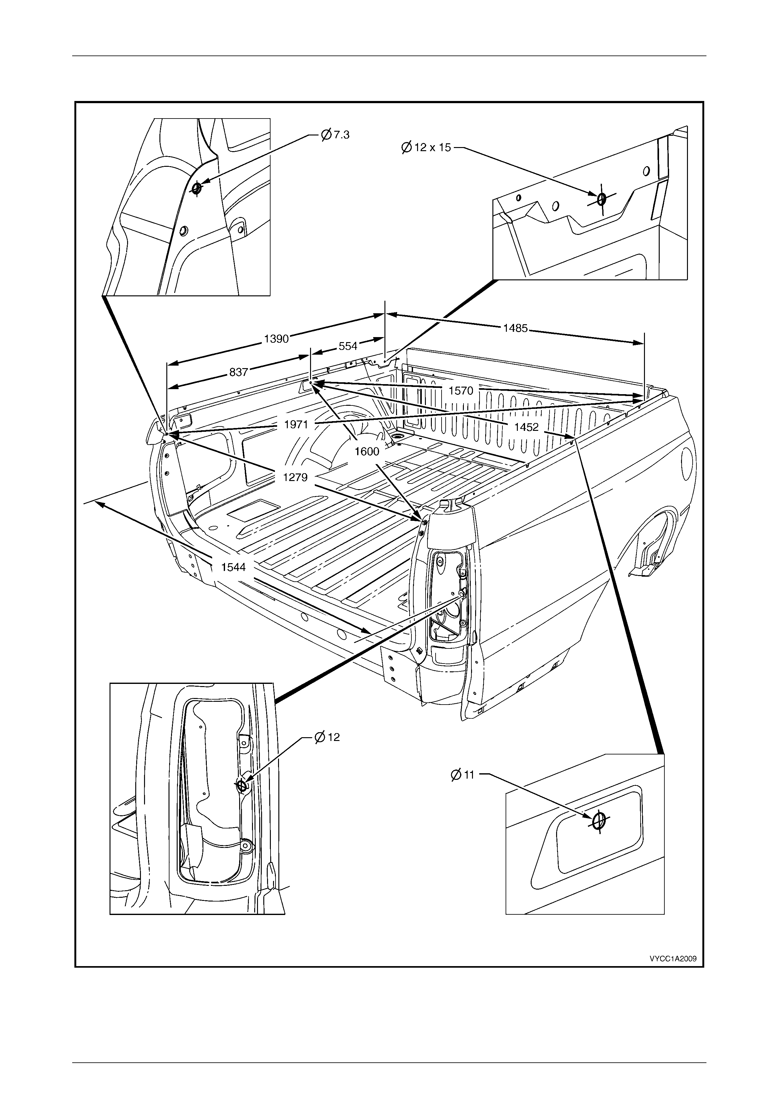
3F Body Construction – Crew Cab Page 3F–17
Rear Body
Figure 3F – 9
Page 3F–17
3F Body Construction – Crew Cab Page 3F–18
4 Body Margins
Figure 3F – 10
Page 3F–18
3F Body Construction – Crew Cab Page 3F–19
Figure 3F – 11
Page 3F–19

3F Body Construction – Crew Cab Page 3F–20
5 Body Sealing, Adhesives and
Deadeners
The commercially available products listed
below will meet the required standards. Other
products may be available that meet the
performance characteristics, however before
their use, the product manufacturer should be
contacted to check its suitability.
This Section details the sealers, adhesives and deadeners used in the body shell. It is imperative that the correct
materials are used and the directions on the product always be followed.
NOTE
When replacing any sealer, adhesive or
deadener, ensure the finish meets that of the
original applica tion.
Weld Through Primer (Item 1)
Although not used in manufacture, Weld-Through Primer is recommended for all service repair lap and flange joints
where Acrylic Spot Weld Sealer (Item 2) is not used. Weld Through Primer aids in corrosion protection of the joint.
Acrylic Spot Weld Sealer (Item 2)
Used in joints that require sealing additional to Joint Sealer (Item 3). It is applie d to the joint flange prior to the mating of
panels. Refer to Figure 3F – 12 to Figure 3F – 15.
Joint Sealer (Item 3)
Primarily used for sealing joints to achieve a watertight seal. It seals notches, cut-outs and holes. Joint sealer should be
applied after priming, prior to application of the top coat. Refer to Figure 3F – 16 to Figure 3F – 21.
Hand Putty (Item 4)
Hand putty, also known as caulking compou nd, is used in the areas marked * in Figure 3F – 21.
Adhesive – Anti-Flutter (Item 5)
While used as a filler between an inner and outer panel to re duce panel flex, Anti-Flutter adhesive also aids rigidity and
assists in dispersing loads over a larger area. Refer to Figure 3F – 22 for locations.
Page 3F–20

3F Body Construction – Crew Cab Page 3F–21
Adhesive – Structu al (Item 6) r
-
r
i t
Critical to the strength and rigidity of the vehicle, the correct adhesive must be used for service repairs. Using an
adhesive that is too weak will reduce the performance of the joint. Using an adhesive that is too strong can also effect the
performance of the joint, compromising the vehicle’s crash performance and safety system’s operation. This adhesive i s
a 2-part system. Refer to Figure 3F – 23 and Figure 3F – 24 for locations.
Spray on Deadener (Item 7)
This deadener is spra yed onto the body shell after painting. It is used in the wheel-wells and on the under side of the
floor pan. A minimum thickness of 1.5 mm is required in these app lications. Refer to Figure 3F – 25 for locations.
Deadene Panels
Deadener panels are sold pre-cut as service parts. They are installed with the coloure d side up and diamond embossed
side down. The panels are installed prior to painting. Some are heat fused to the body shell. Refer to Figure 3F – 26 –
Figure 3F – 31 for locations.
Commercially Available Sealer, Adhesi ve and Dead ener Equ valen s
Item No. Item Name Manufacturer Product Name
1 Weld Through Primer Refer to supplier
2 Acrylic Spot Weld Sealer Lord (Fusor) Fusor #800 / #801
3 Joint Sealer Sprayable: Lord (Fusor)
Extruded beads: Lord (Fusor)
3M
Visible Seams
-self leveling: Lord (Fusor)
3M
-non sag: Lord (Fusor)
3M
Fusor #802
Fusor #800 / #801
Automix 8308
Fusor #122 / #125
Automix 8307
Fusor #123 / #126
Automix 8308
4 Hand Putty Lord (Fusor) Fusor #800 / #801
Automix 8307
5 Adhesive – Anti Flutter Lord (Fusor) Fusor #124
6 Adhesive – Structural (Two-Part) Lord (Fusor)
3M Fusor #108 B
Automix 8115
7 Spray-on Deadener Henkel Terophon 2000-13
NOTE
Special tools may be required to apply some
materials, refer to the supplier for further
information.
Page 3F–21
3F Body Construction – Crew Cab Page 3F–22
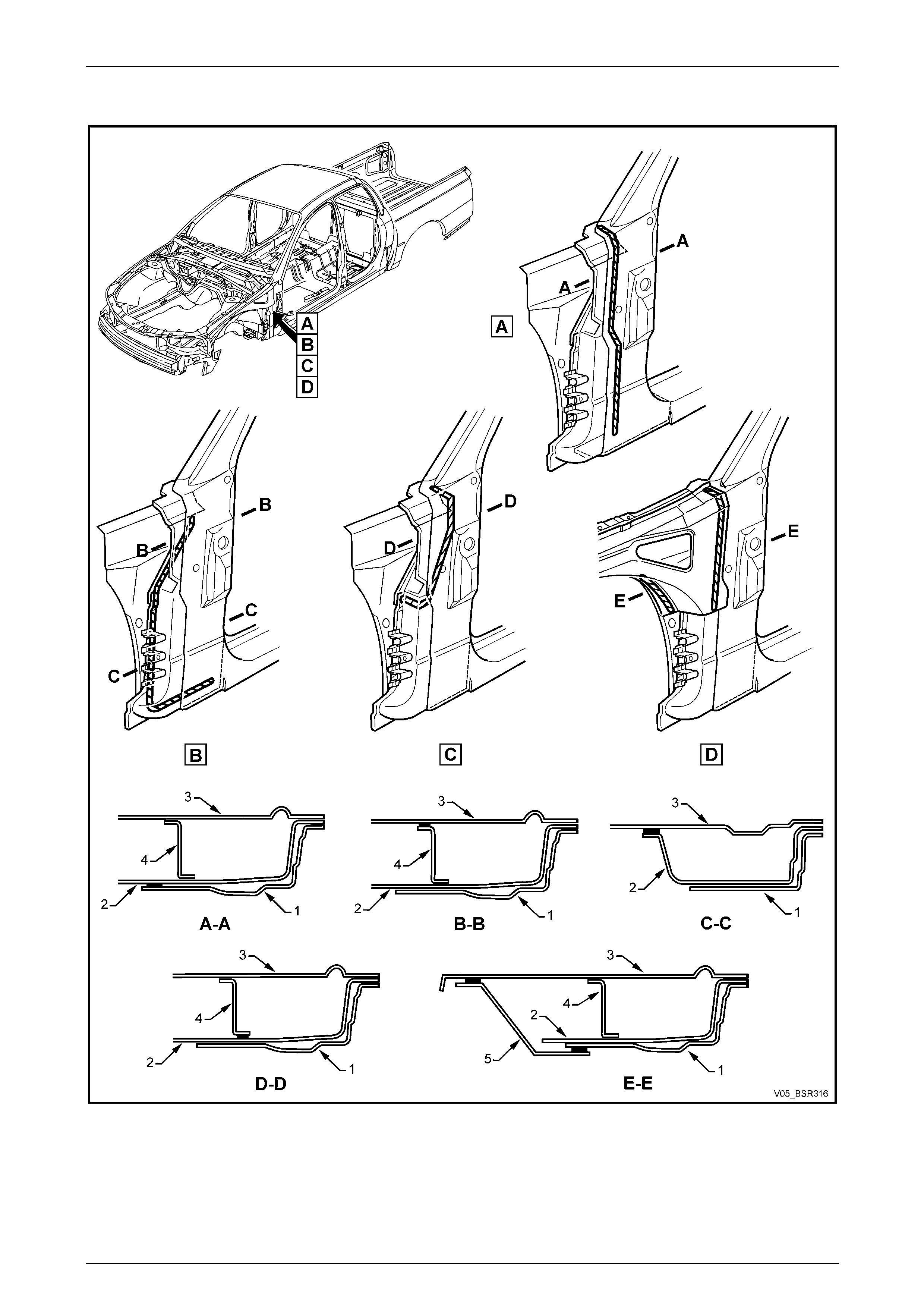
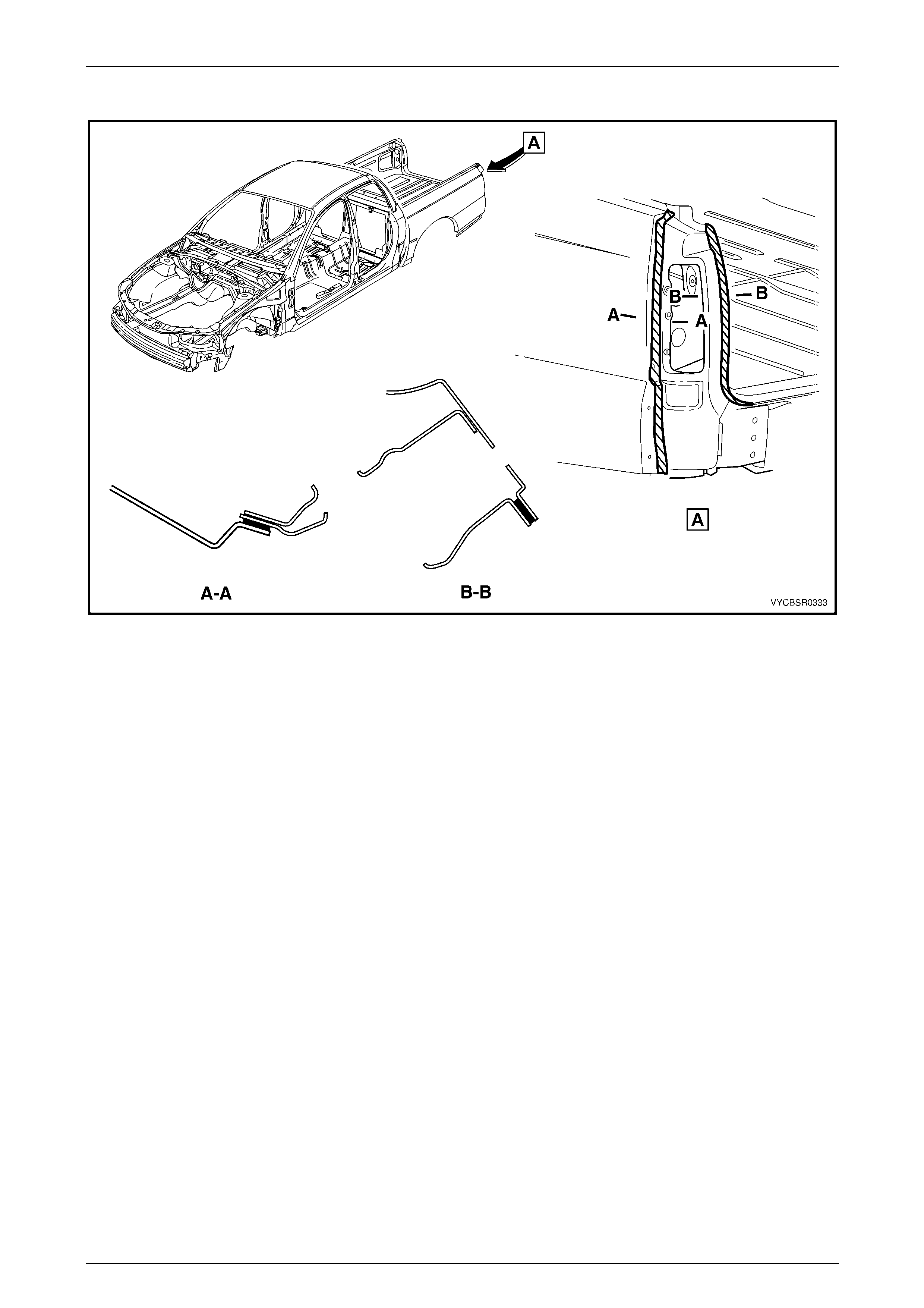
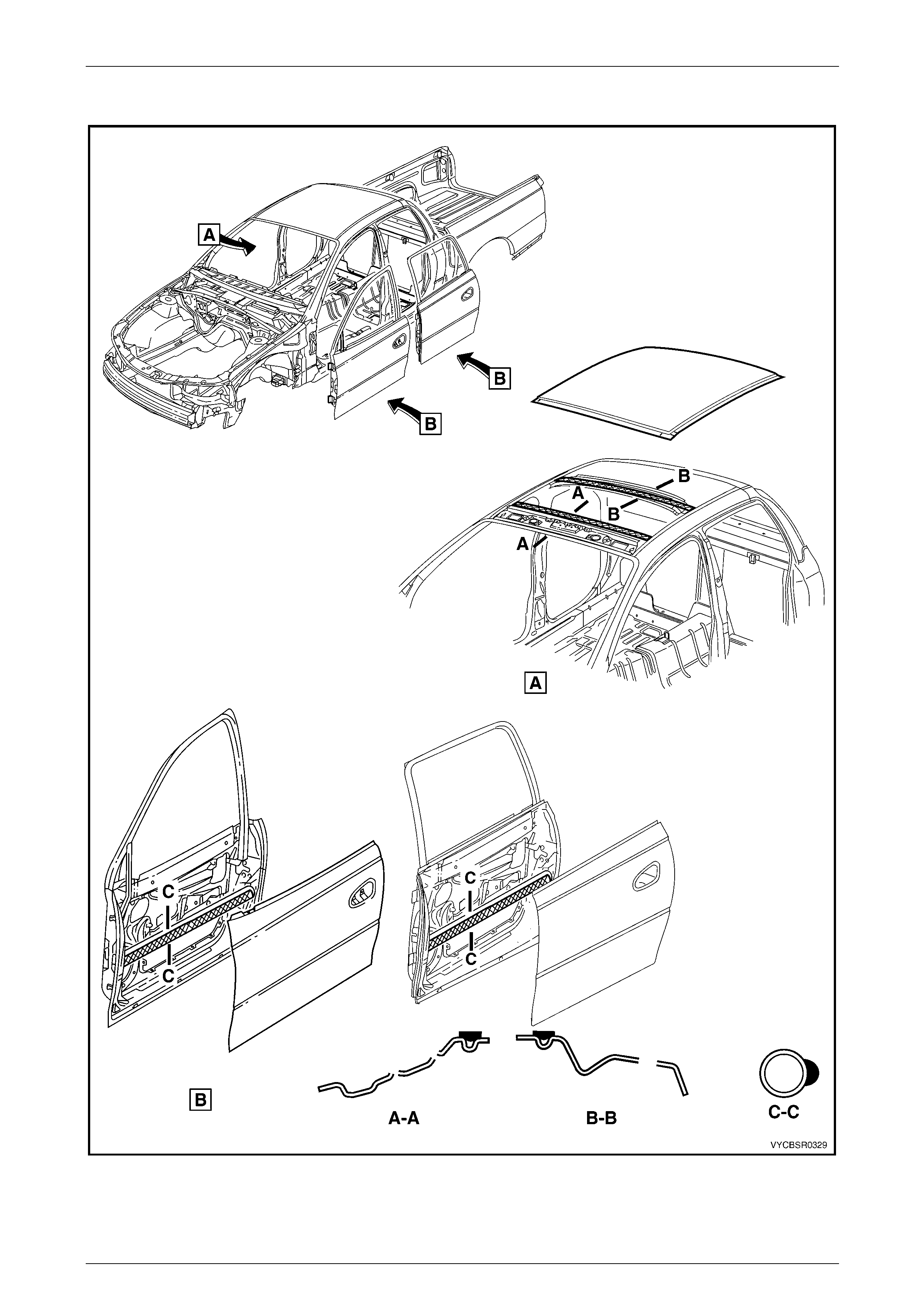
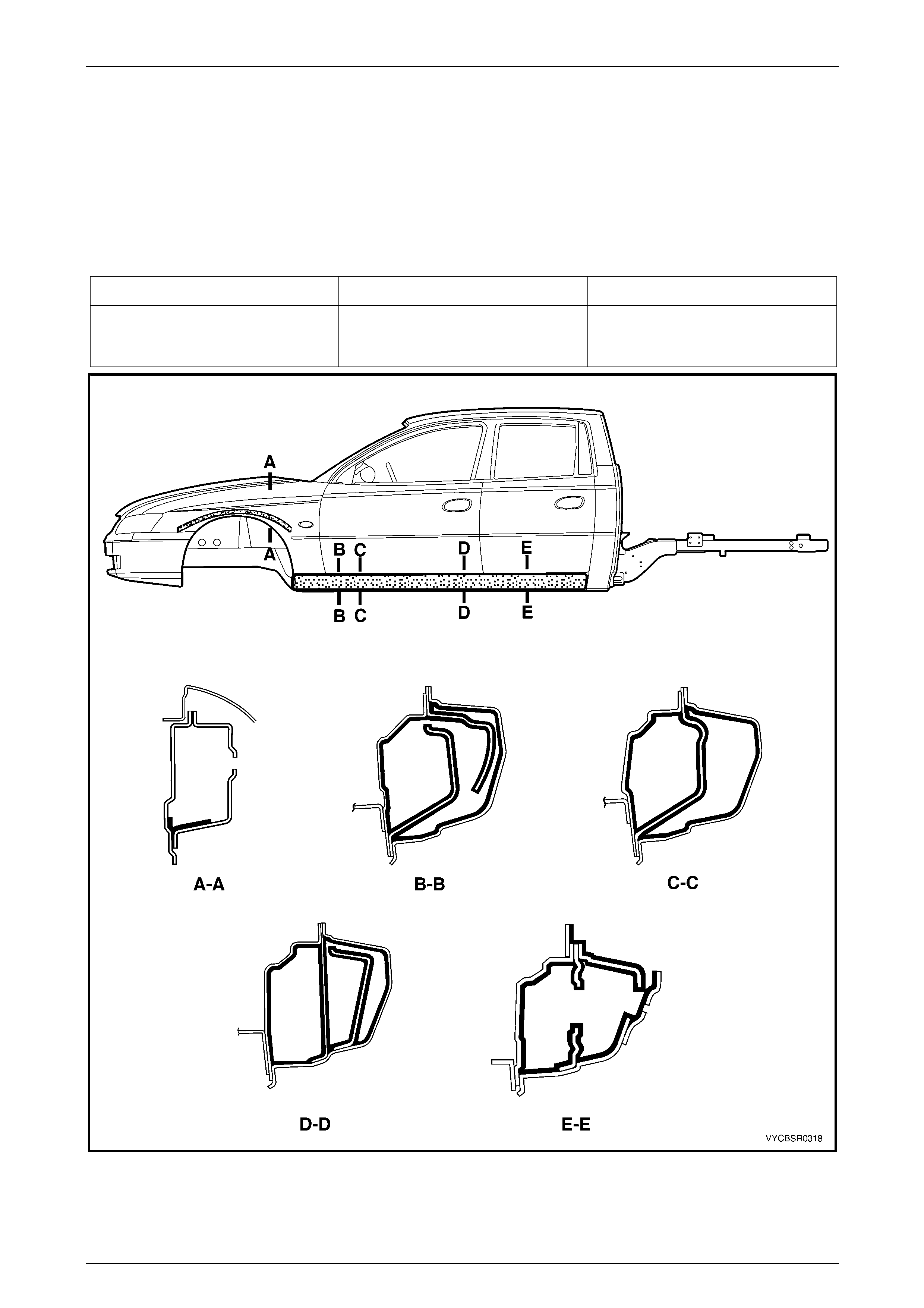
5.1 Acrylic Spot Weld Sealer (Item 2)
Figure 3F – 12
Legend
1 Door Opening Frame
2 Hinge Pillar Reinforcement
3 Hinge Pillar Inner Panel
4 Hinge Pillar Closing Plate
5 Front Wheelhouse Panel Upper Side Rail
Page 3F–22
3F Body Construction – Crew Cab Page 3F–23
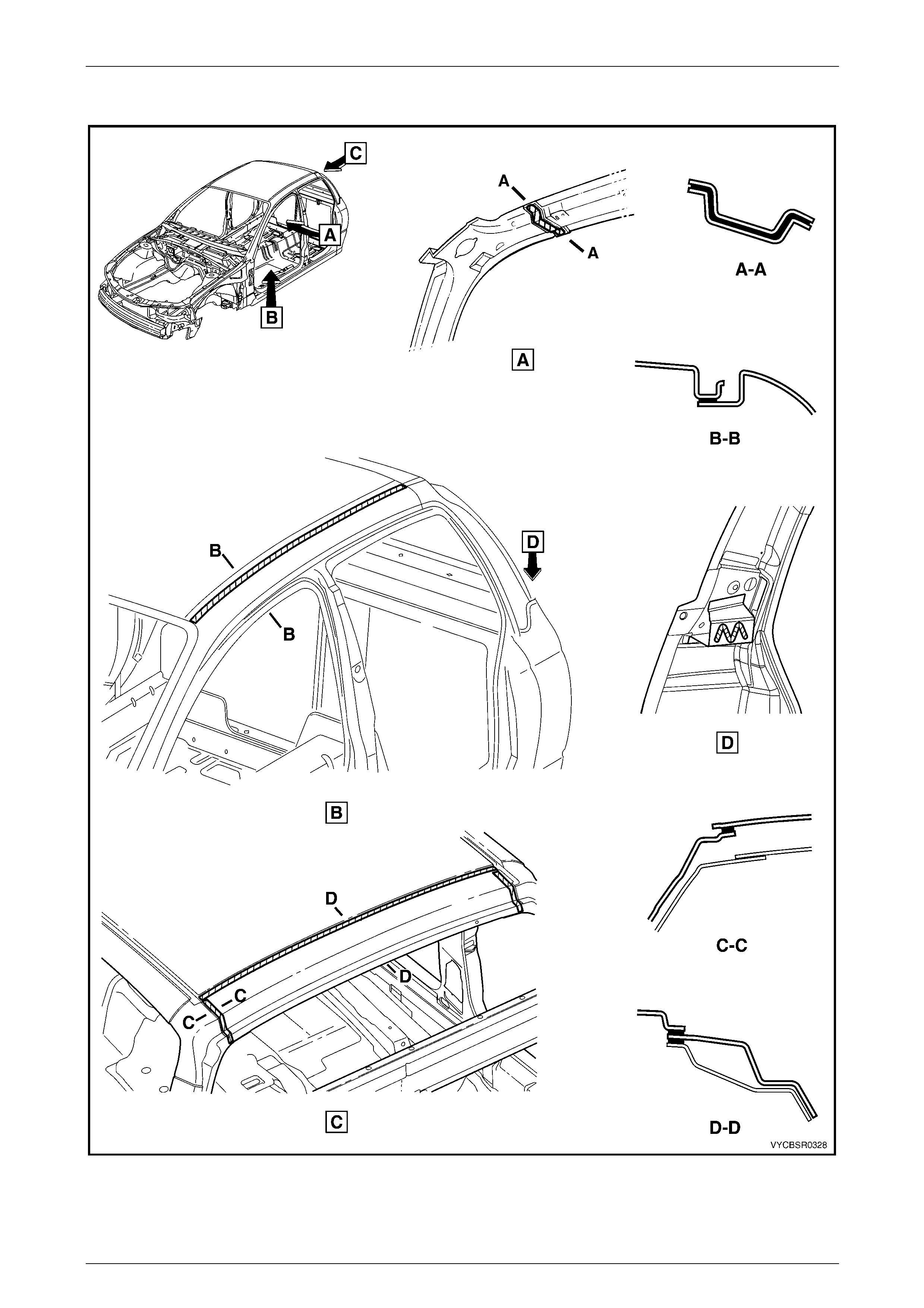
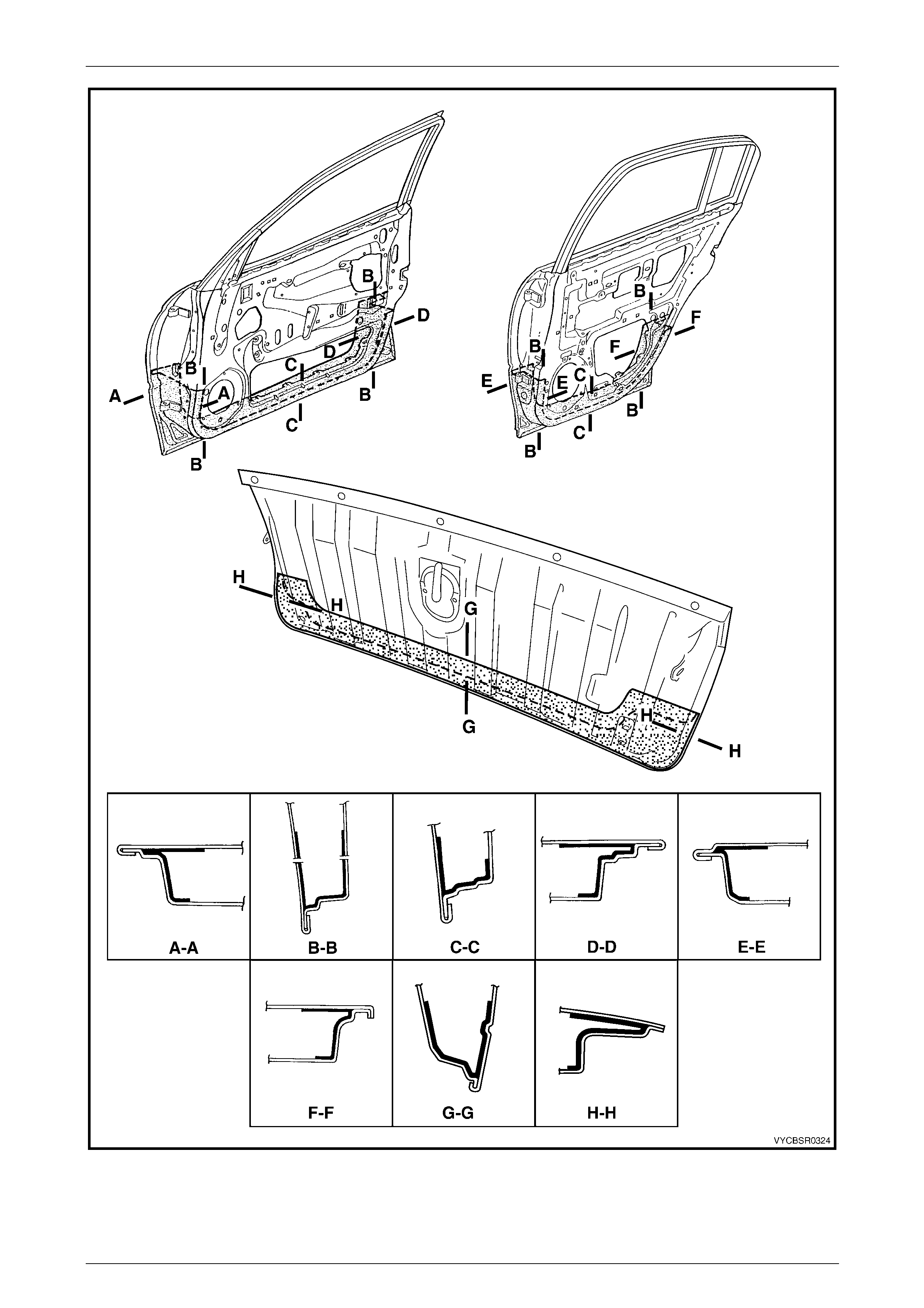
Acrylic Spot Weld Sealer (Item 2) Continued
Figure 3F – 13
Page 3F–23
3F Body Construction – Crew Cab Page 3F–24
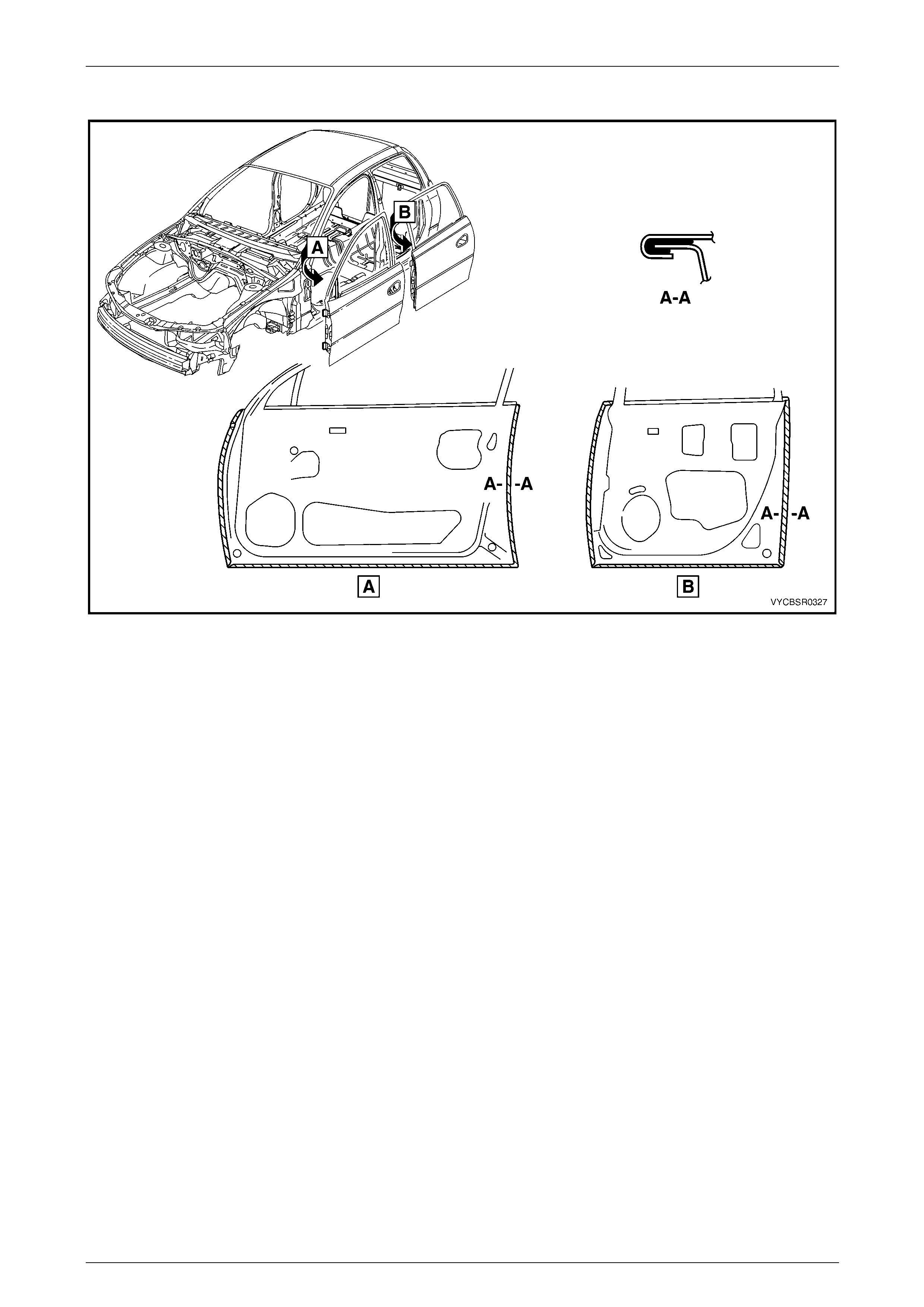
Acrylic Spot Weld Sealer (Item 2) Continued
Figure 3F – 14
Page 3F–24
3F Body Construction – Crew Cab Page 3F–25
Acrylic Spot Weld Sealer (Item 2) Continued
Figure 3F – 15
Page 3F–25
3F Body Construction – Crew Cab Page 3F–26
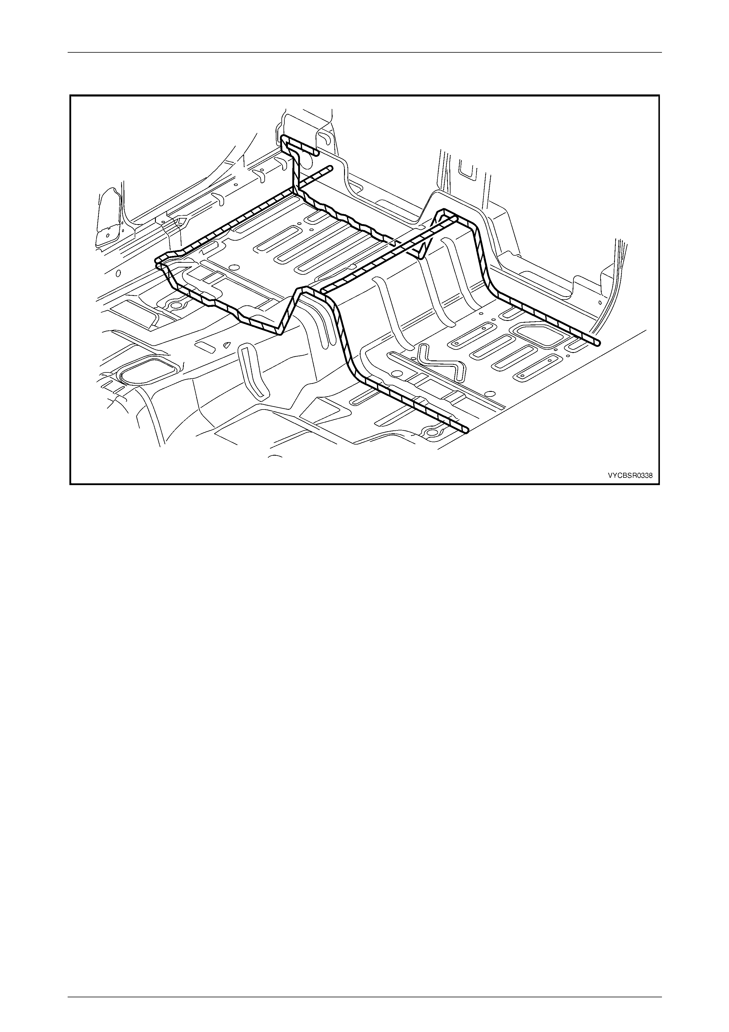
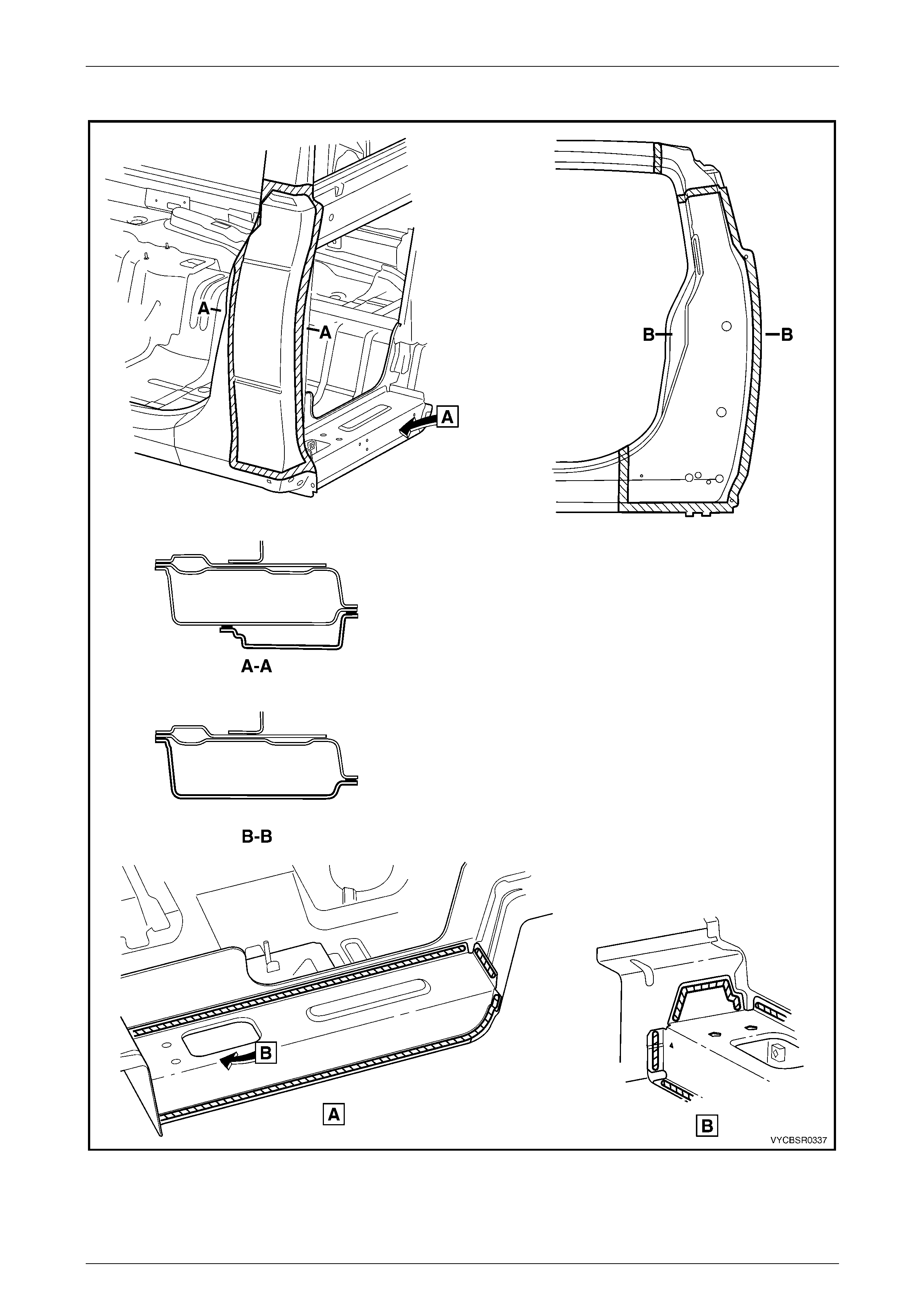
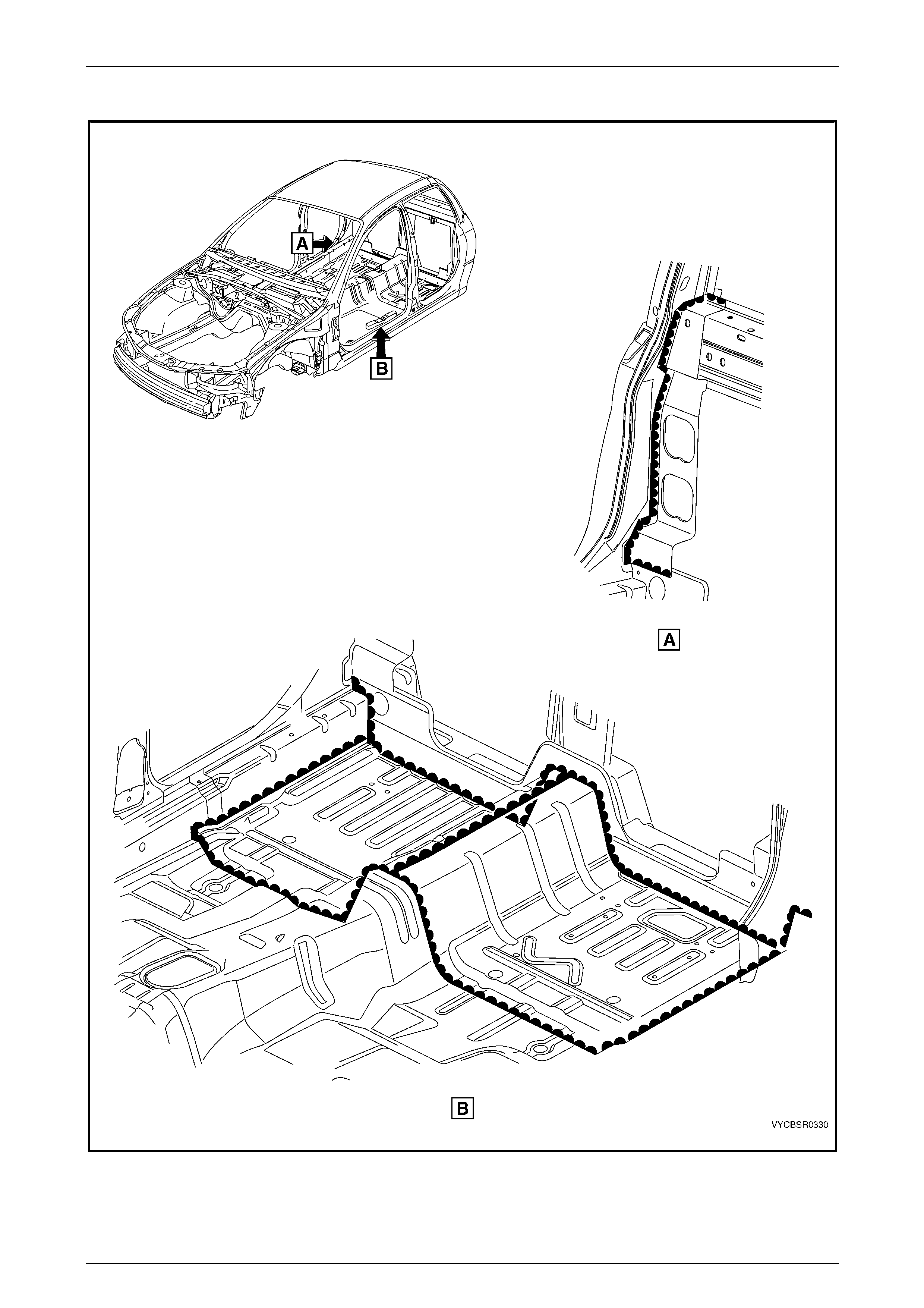
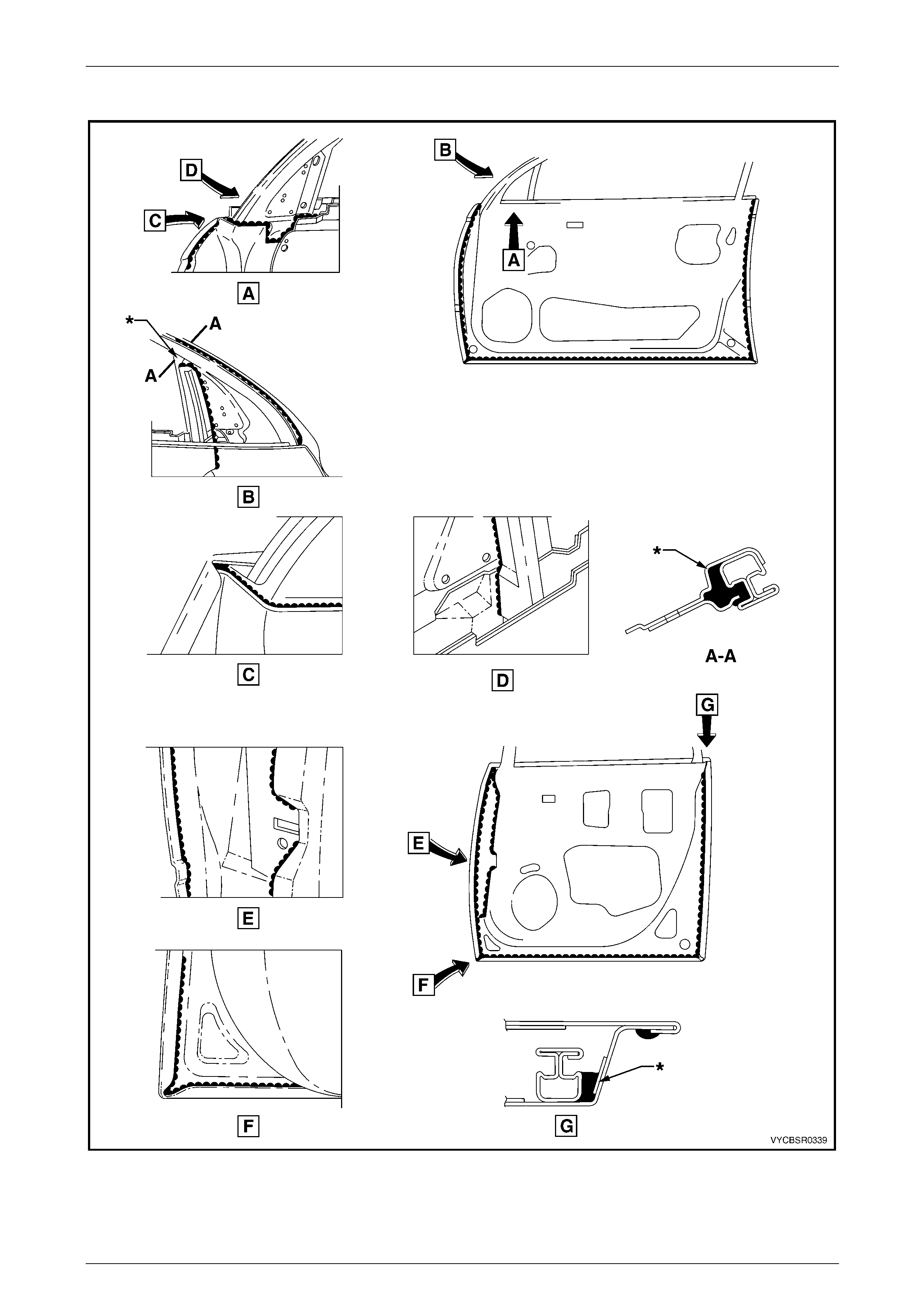
5.2 Joint Sealer (Item 3)
Figure 3F – 16
Page 3F–26
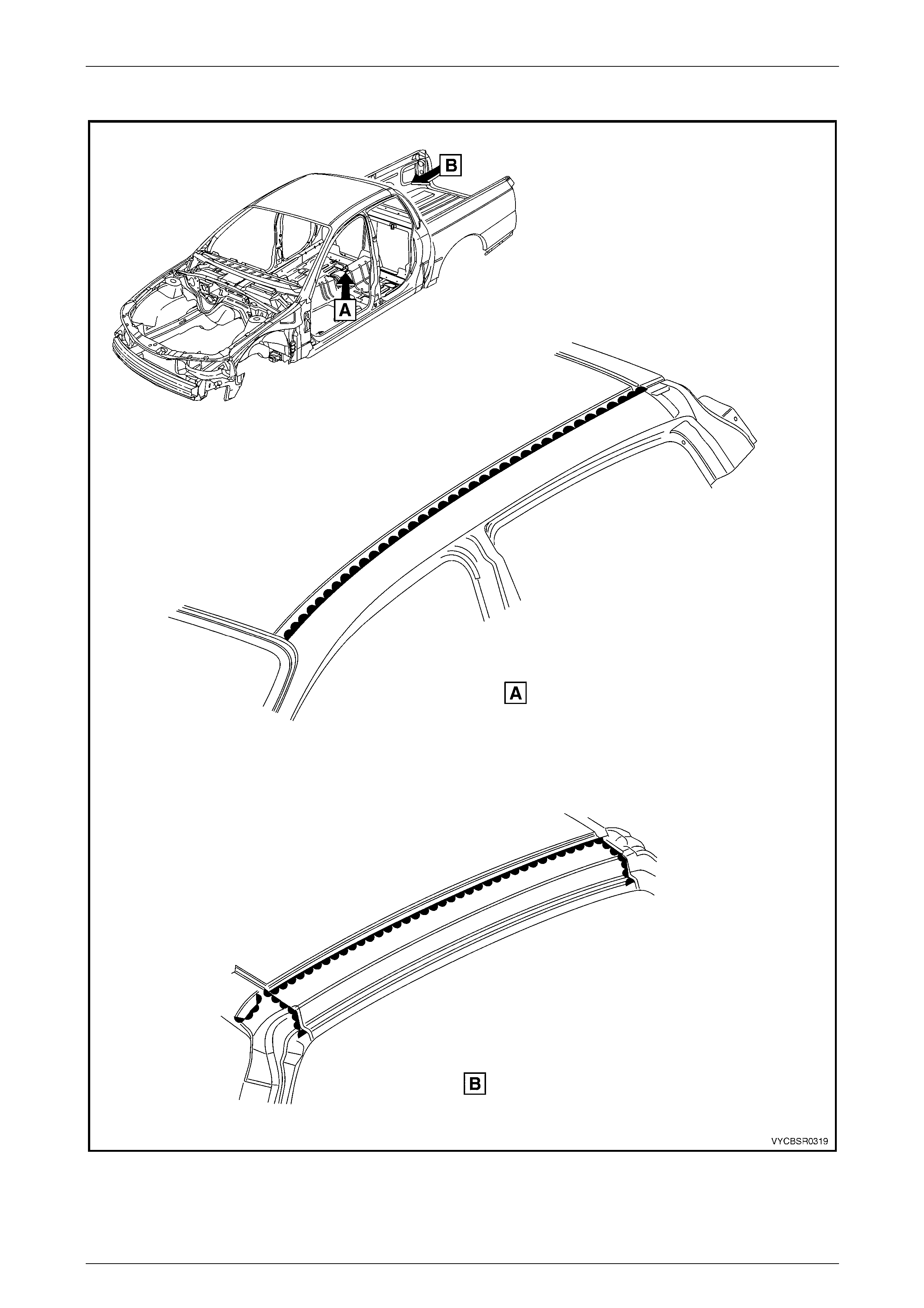
3F Body Construction – Crew Cab Page 3F–27
Joint Sealer (Item 3) Continued
Figure 3F – 17
Page 3F–27
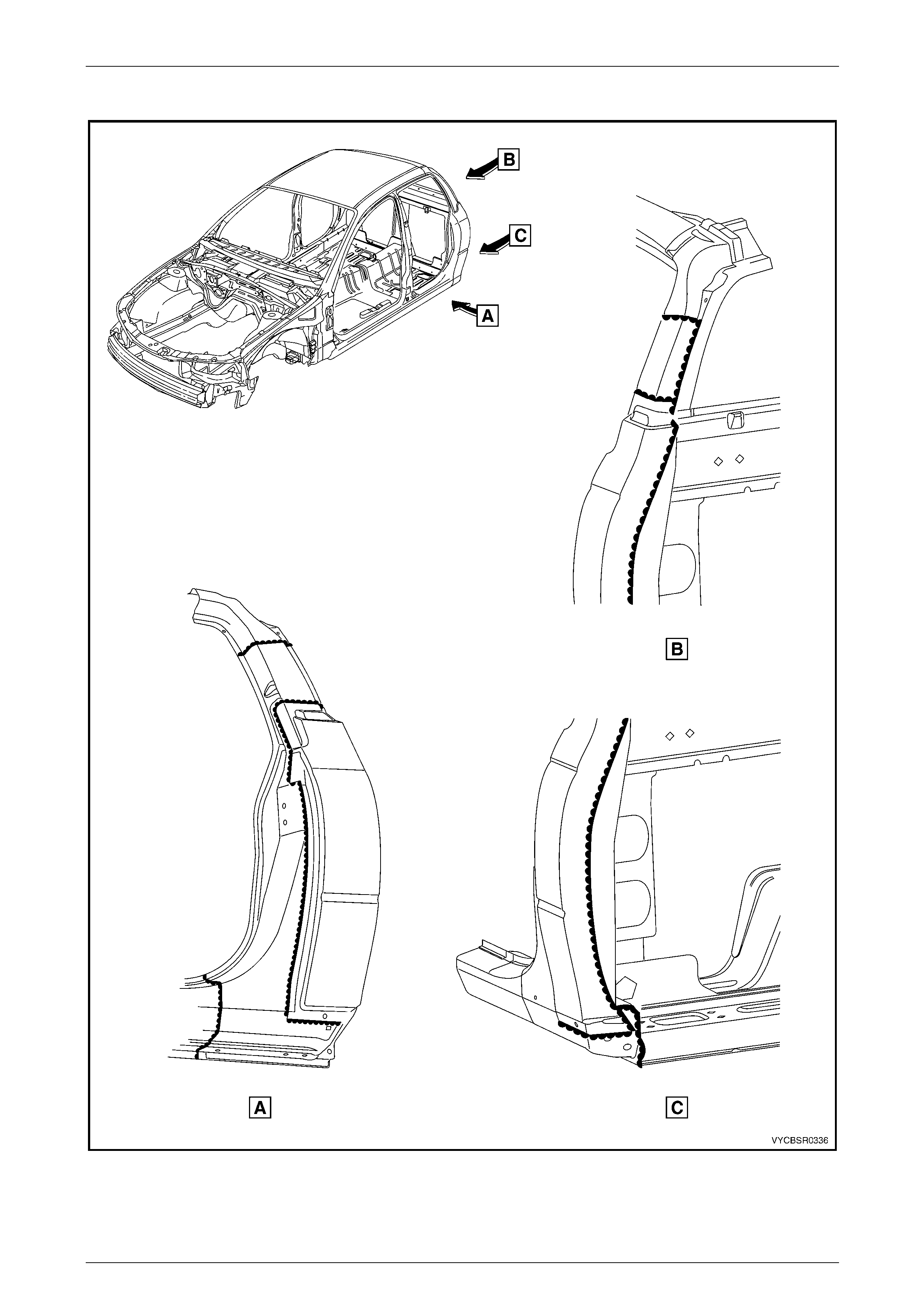
3F Body Construction – Crew Cab Page 3F–28
Joint Sealer (Item 3) Continued
Figure 3F – 18
Page 3F–28
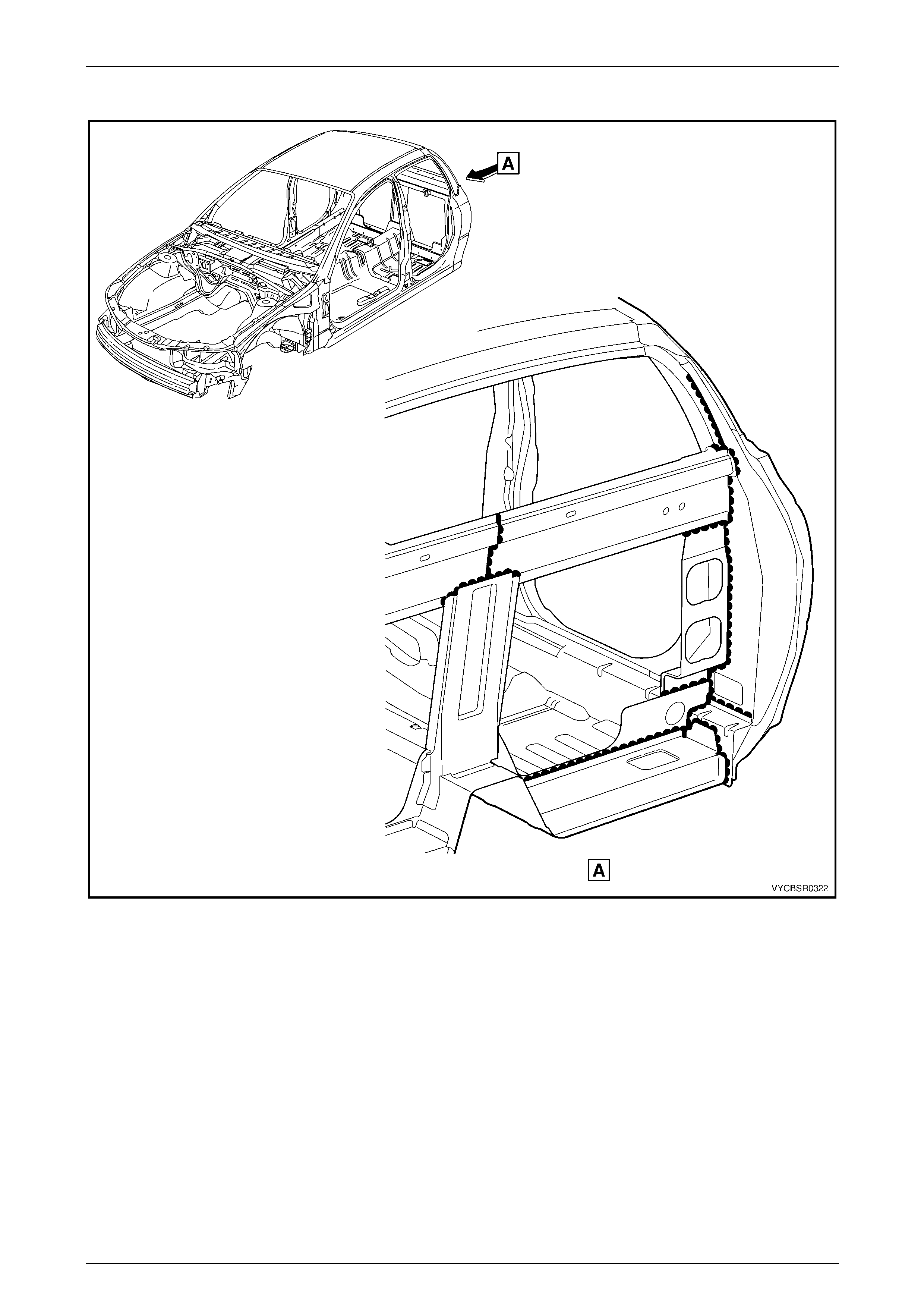
3F Body Construction – Crew Cab Page 3F–29
Joint Sealer (Item 3) Continued
Figure 3F – 19
Page 3F–29
3F Body Construction – Crew Cab Page 3F–30
Joint Sealer (Item 3) Continued
Figure 3F – 20
NOTE
When the inner rear body panel is installed, joint
sealer is applied around its perimeter between
the panel and body.
Page 3F–30
3F Body Construction – Crew Cab Page 3F–31
Joint Sealer (Item 3) Continued and Hand Putty (Item 4)
Figure 3F – 21
Page 3F–31
3F Body Construction – Crew Cab Page 3F–32
5.3 Adhesive – Anti-Flutter (Item 5)
Figure 3F – 22
Page 3F–32
3F Body Construction – Crew Cab Page 3F–33
5.4 Adhesive – Structural (Item 6)
Figure 3F – 23
Page 3F–33
3F Body Construction – Crew Cab Page 3F–34
Adhesive – Structural (Item 6) Continued
Figure 3F – 24
Page 3F–34
3F Body Construction – Crew Cab Page 3F–35
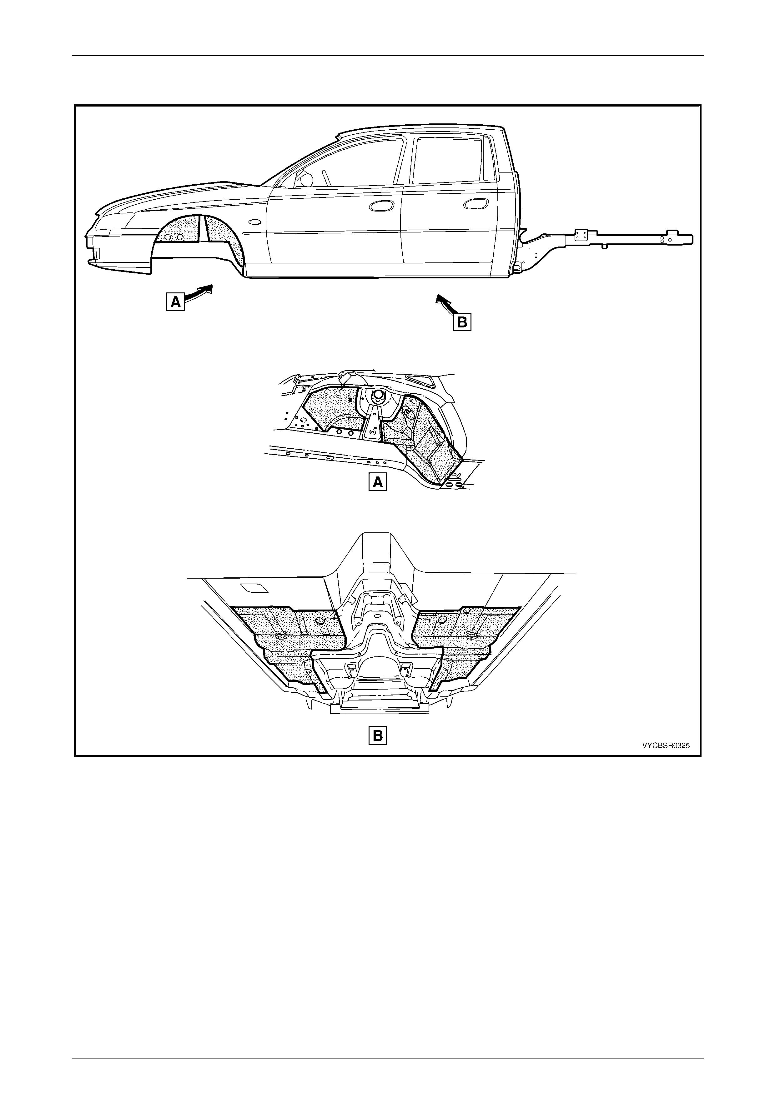
5.5 Spray-on Deadener
Figure 3F – 25
Page 3F–35
3F Body Construction – Crew Cab Page 3F–36
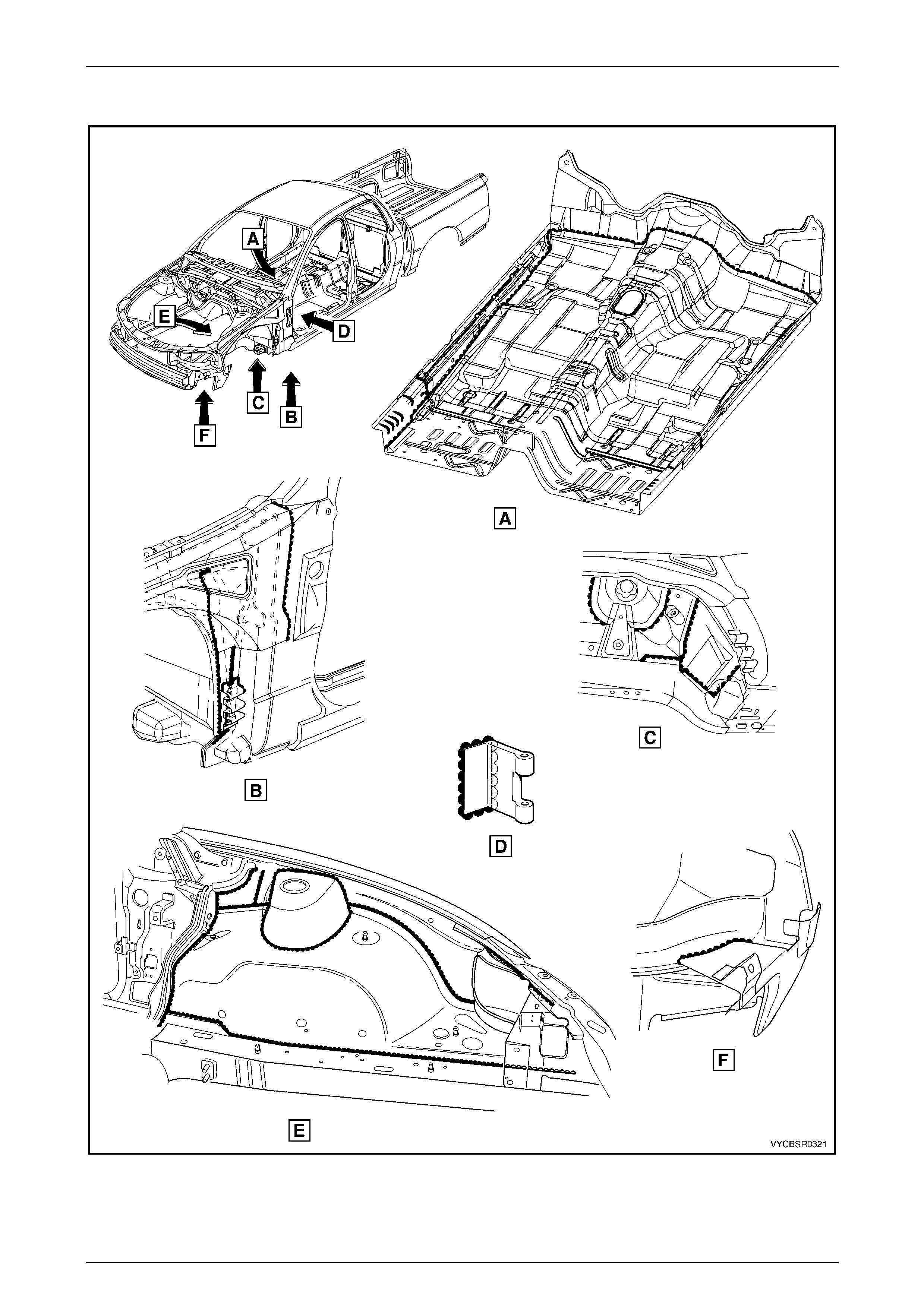
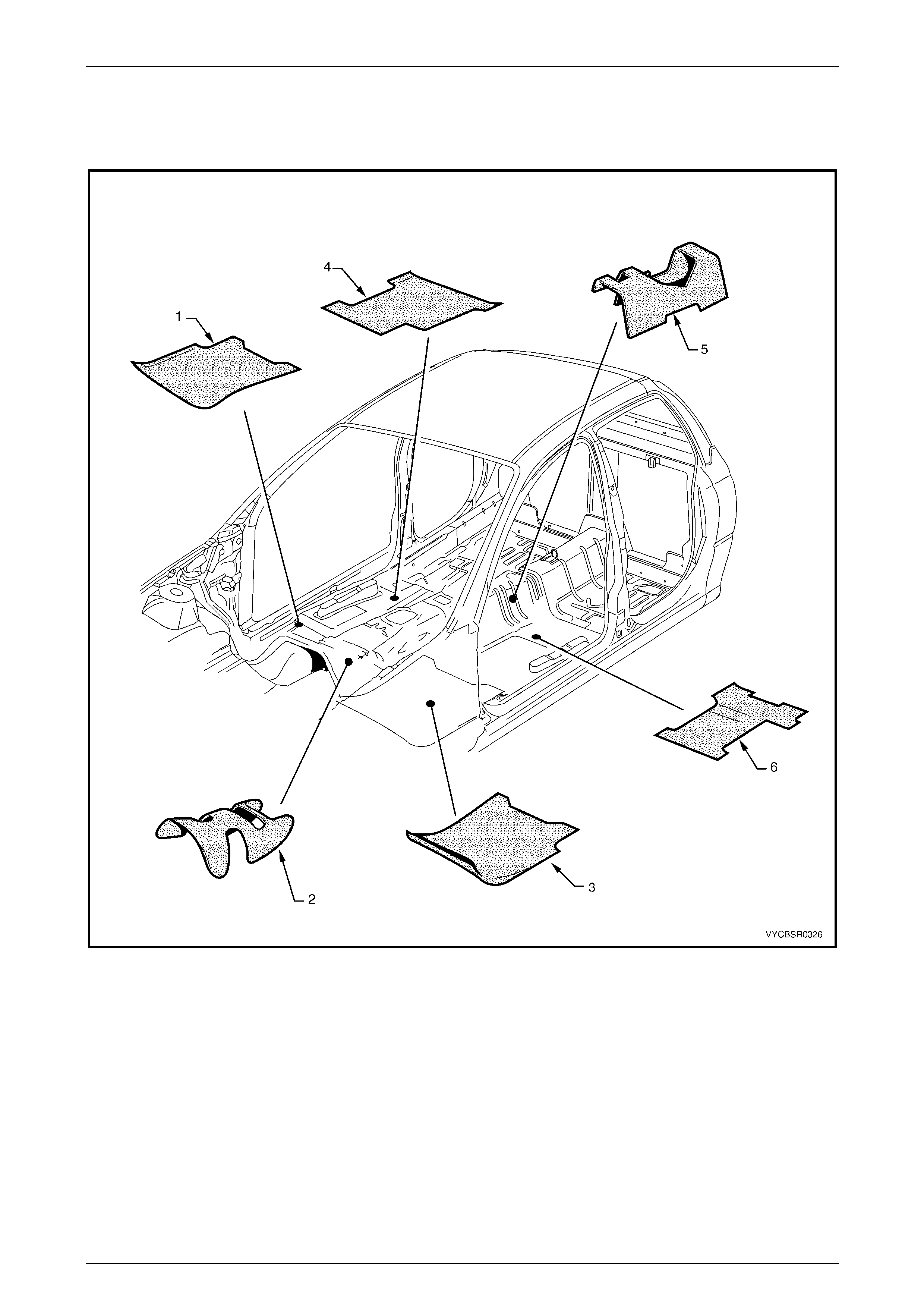
5.6 Deadeners and Insulators
The deadeners shown are heat fusible type. T hey are to be installed with the diamond e m bossed side down. Use a heat
gun, heat lamps or such to cure each deadener sheet.
Figure 3F – 26
Legend
1 Deadener – Front Floor, Right-hand
2 Deadener – Front Floor, Centre
3 Deadener – Front Floor, Left-hand
4 Deadener – Rear Floor, Right-hand
5 Deadener – Rear Floor, Centre
6 Deadener – Floor Rear, Left-hand
A retainer (1) is used at five places to attach the dash panel lower insulator outer (2) to the engine compartment side of
the dash panel, refer to Figure 3F – 27.
Page 3F–36
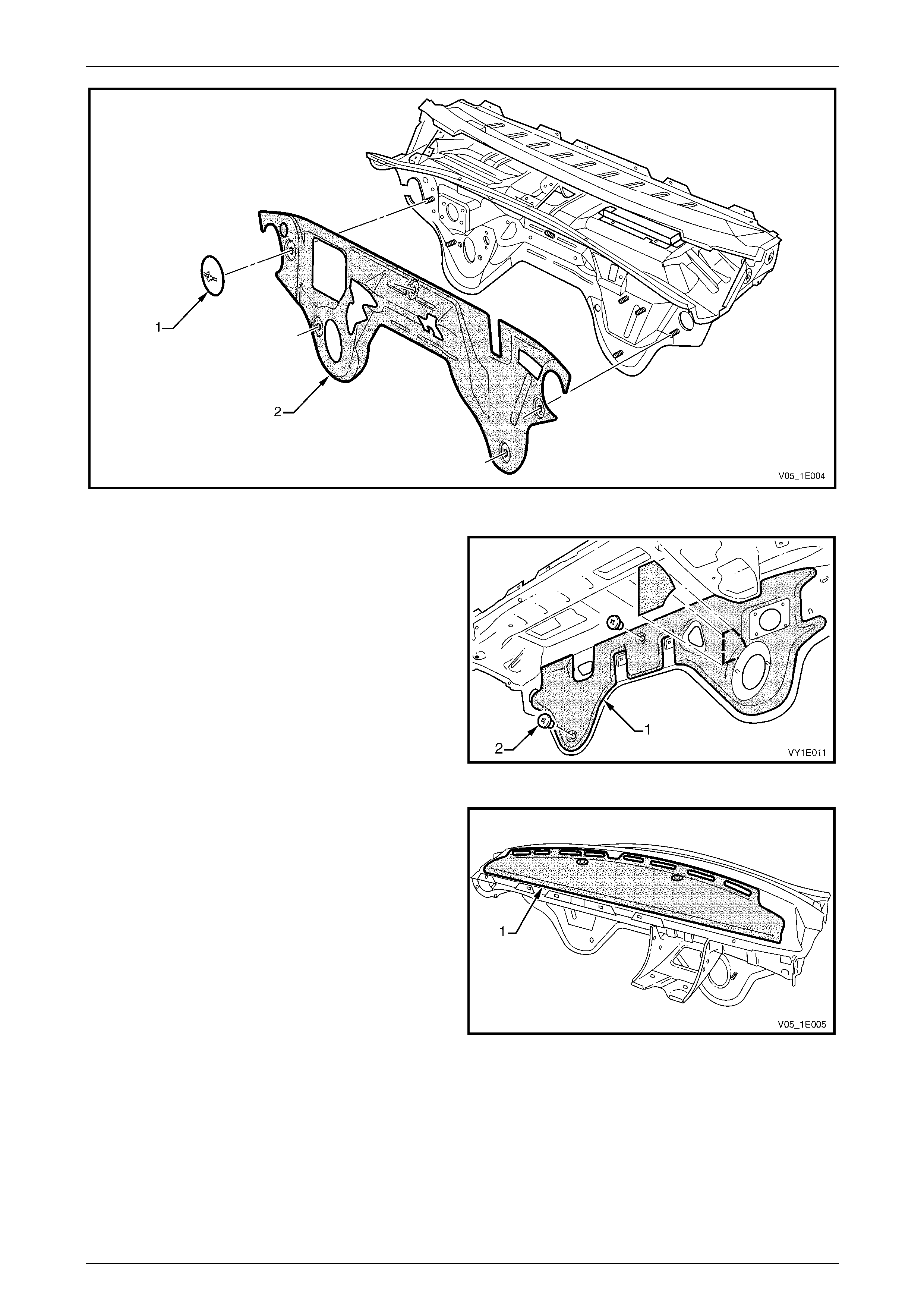
3F Body Construction – Crew Cab Page 3F–37
Figure 3F – 27
The dash panel lo wer insulator inner (1) is attached to the
dash panel with two retainers (2).
Figure 3F – 28
The dash panel upper insulator (1) is adhered to the dash
panel and care is required during removal. If required, apply
contact adhesive to the insulator prior to affixing it to the
new dash panel and ensure it follows the form of the dash
panel.
If a new insulator is being fitted, remove the backing p aper
prior to fitting and apply.
Figure 3F – 29
Page 3F–37
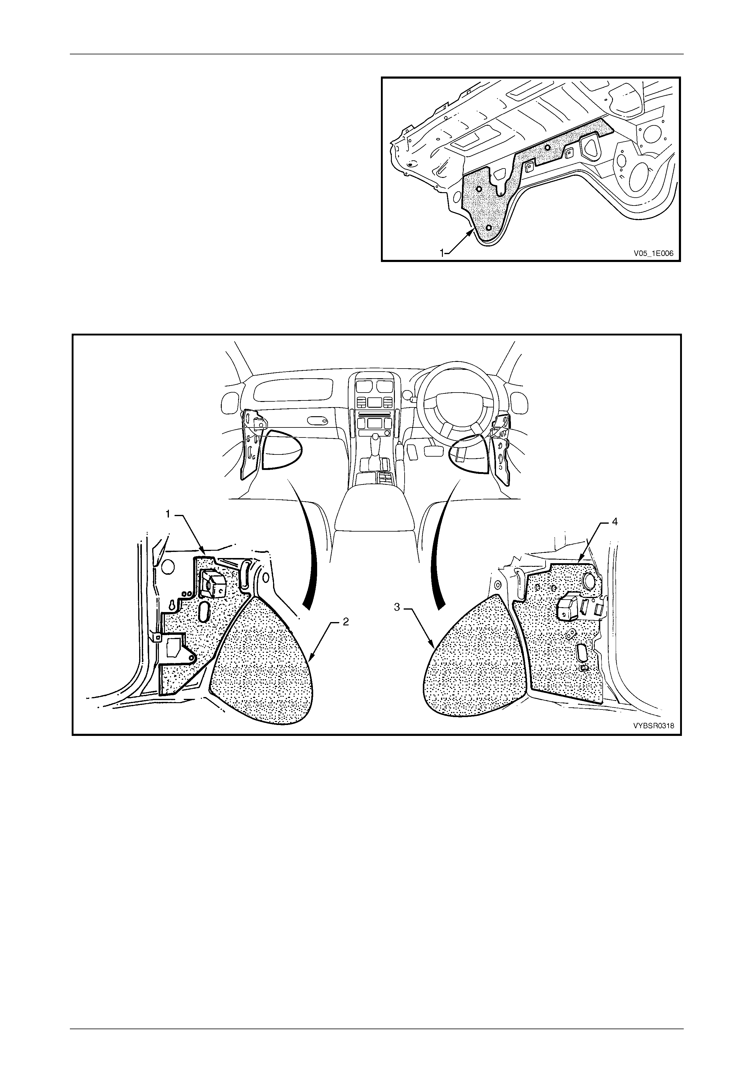
3F Body Construction – Crew Cab Page 3F–38
The dash panel lower deadener (1) is a heat-fusible type.
Install it in position with the diamond embossed side to the
panel. Use a heat gun, heat lamps or such, to cure the
deadener. Smooth the deadener with a roller or such to
expel any air bubbles and to maximise adhesion.
Figure 3F – 30
The deadeners and insulators in Figure 3F – 31 are self adhesive. Remove the backing paper and attach the insulator
ensuring any cut-outs align with brackets, etc. Smooth the insulator firmly into position.
Figure 3F – 31
Legend
1 Insulator – Cowl Side, Left-hand
2 Deadener – Front Floor Extension, Left-hand 3 Deadener – Front Floor Extension, Right-hand
4 Insulator – Cowl Side, Right-hand
Page 3F–38
3F Body Construction – Crew Cab Page 3F–39
6 Cavity Wax
Crew Cab body and structural panels are constructed from high quality cor r osion resistant materials.
Following repairs, to maintain the anti-corrosive properties of the vehicle, o nce the paint is thoroughly dr y apply cavity
wax within any repaired b ox sections, areas inaccessible to paint, and to the areas shown below. Refer to the table for
equivalent products to those used in man ufacture.
Cavity Wax Equivalents
Item No. Equivalent Manufacturer Equivalent Product Name
8 Henkel
Terotex HV 8377/65
Nox Rust Hi-Wax 100B
Terasol 800113 (Aerosol pack)
Figure 3F – 32
Page 3F–39
3F Body Construction – Crew Cab Page 3F–40
Figure 3F – 33
Page 3F–40