6A Cabin Floor – Sedan, Wagon, Coupe and AWD Wagon Page 6A-1
Page 6A-1
Section 6A
Cabin Floor – Sedan, Wagon, Coupe and AWD
Wagon
ATTENTION
Before performing any service operation or other procedure described in this Section, refer to Section 2
Precautions in this Supplement and Section 00 Warnings, Cautions and Notes in the MY2005 VZ Service
Information for correct workshop practices with regard to safety and/or property damage.
The structure of the body shell has been
developed using complex design and
development techniques. In addition to
meeting all required standards, the vehicle
body is also a critical part of the overall safety
systems. It is therefore imperative the repair
procedures described here are adhered to
during all vehicle body repairs.
1 General Description ...............................................................................................................................2
1.1 Cabin Floor Components...................................................................................................................................... 2
2 Service Operations.................................................................................................................................4
2.1 Front Floor Panel Extension – Replace ............................................................................................................... 4
Remove................................................................................................................................................................... 4
Replace................................................................................................................................................................... 5
2.2 Front Floor Panel Extension – Partial Replace.................................................................................................... 7
Remove................................................................................................................................................................... 7
Replace................................................................................................................................................................... 8
2.3 Front Floor Panel Assembly – Replace.............................................................................................................. 10
Remove................................................................................................................................................................. 10
Replace................................................................................................................................................................. 12
2.4 Inner Rocker Panel Assembly – Replace........................................................................................................... 14
Remove................................................................................................................................................................. 14
Replace................................................................................................................................................................. 15
2.5 Right-hand Transmission Support Bracket – Replace ..................................................................................... 17
Remove................................................................................................................................................................. 17
Replace................................................................................................................................................................. 17
2.6 Seat Inner Bracket Assembly – Replace............................................................................................................ 19
Remove................................................................................................................................................................. 19
Replace................................................................................................................................................................. 20
2.7 Seat Outer Bracket Assembly – Replace........................................................................................................... 21
Remove................................................................................................................................................................. 21
Replace................................................................................................................................................................. 22
2.8 Propeller Shaft Hanger Assembly – Replace..................................................................................................... 23
Remove................................................................................................................................................................. 23
Replace................................................................................................................................................................. 24
2.9 Left-hand Transmission Support Bracket – Replace........................................................................................ 25
Remove................................................................................................................................................................. 25
Replace................................................................................................................................................................. 26
6A Cabin Floor – Sedan, Wagon, Coupe and AWD Wagon Page 6A-2
Page 6A-2
1 General Description
This Section describes the replacement procedures for the cabin floor component s of the body structure.
For the servicing of the rear floor components refer to:
• Section 10A Body Rear – Sedan
• Section 10B Body Rear - Wagon and AW D Wagon
• Section 10D Body Rear - Coupe
Removal of bolt-on panels and mecha nica l components is not covered. For information on the removal of these parts,
reference must be made to the appropriate Section in the MY2005 VZ Service Information.
NOTE
• When repairing the cabin floor of the vehicle,
care must be taken to ensure the structure is
returned to its original production
configuration.
• It is imperative that the correct body
adhesives, sealers, deadeners and cavity
waxes are used when repairing the body
structure. Refer to Section 3 Body
Construction for details of the correct
materials and their commercially available
equivalents.
1.1 Cabin Floor Components
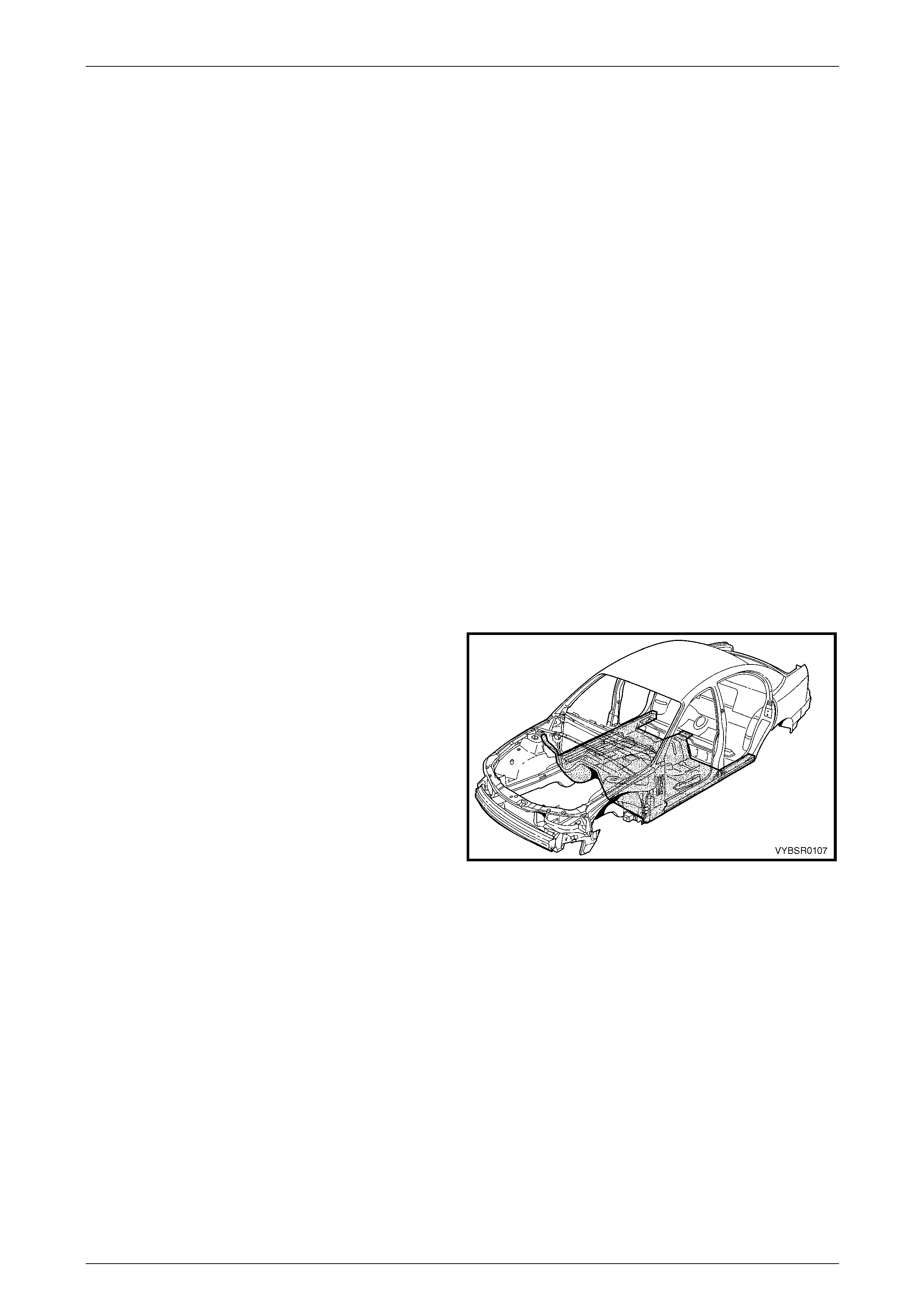
The shaded components in Figure 6A – 1 are the cabin floor
components dealt with in this Section.
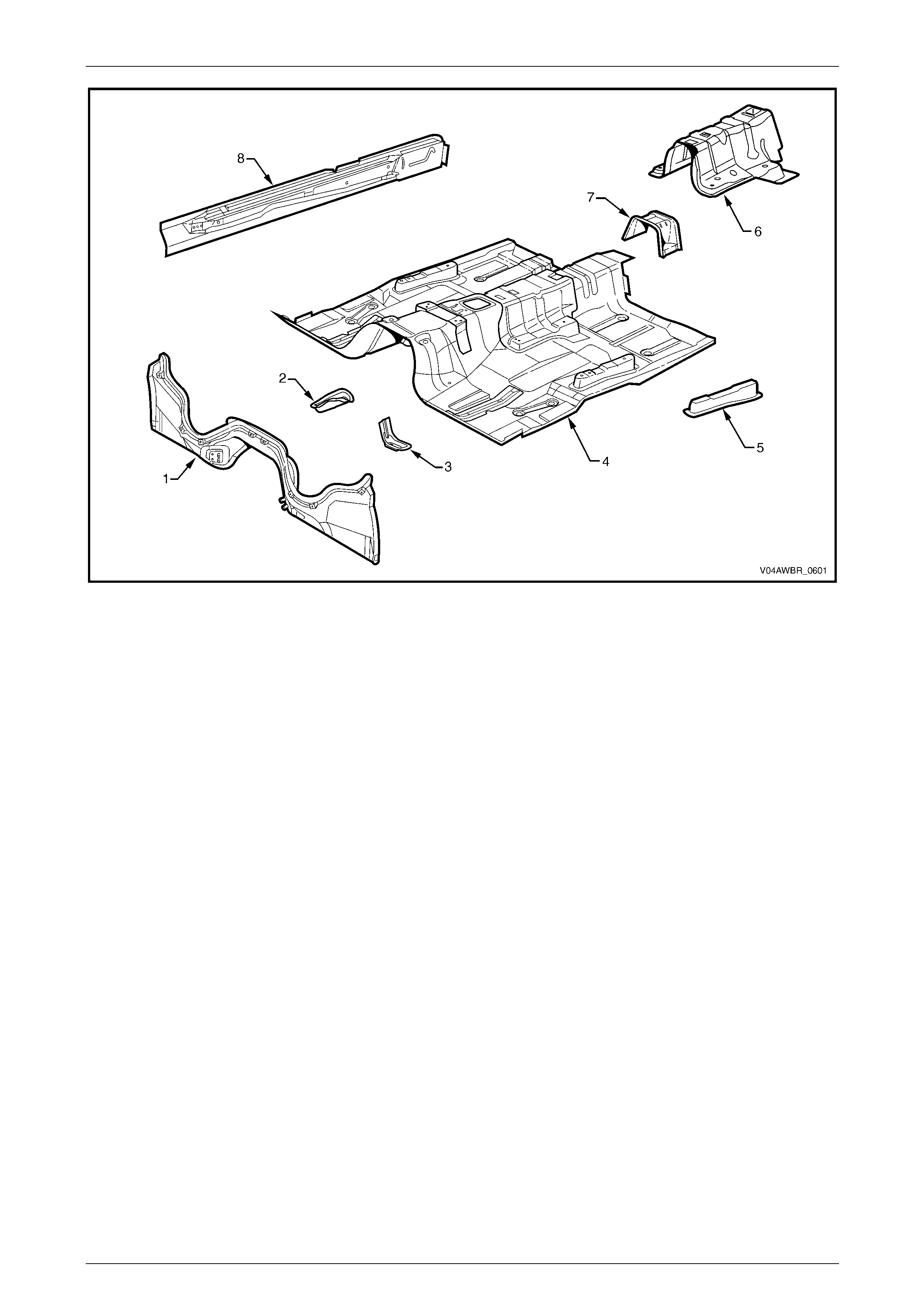
The components and assemblies shown in Figure 6A – 2
and are the serviceable parts that form the basis of the
repair procedures in this Section. For a detailed view of the
body components, refer to Section 3 Body Construction.
NOTE
Always refer to an Authorised Retailer for spare
parts availability configurations.
Figure 6A – 1
6A Cabin Floor – Sedan, Wagon, Coupe and AWD Wagon Page 6A-3
Page 6A-3
Figure 6A – 2
Legend
1 Front Floor Panel Extension
2 Transmission Support Bracket, Right-hand / Left-hand
(except AWD)
3 Transmission Support Bracket, Left-hand (AWD Only)
4 Front Floor Assembly
5 Seat Outer Bracket Assembly, Right-hand / Left-hand
6 Seat Inner Bracket Assembly
7 Propeller Shaft Hanger Assembly
8 Inner Rocker Panel Assembly, Right-hand / Left-hand
6A Cabin Floor – Sedan, Wagon, Coupe and AWD Wagon Page 6A-4
Page 6A-4
2 Service Operations
2.1 Front Floor Panel Extension – Replace
Remove
1 Remove the adjacent bolt-on panels a nd components
as described in the appropriate Section of the MY2005
VZ Service Information.
2 Secure the vehicle on a suitable fixture. As a
minimum, support the appropriate structural s ections
of the vehicle on safety stands.
3 Remove the dash panel asse mbly,
refer to Section 5 Cockpit Module.
4 Remove the adjoining panels as required, refer to the
relevant Section in this Supplement.
5 Using a scraper and heat gun, remove the body sealer
and deadener from the front floor and floor extension
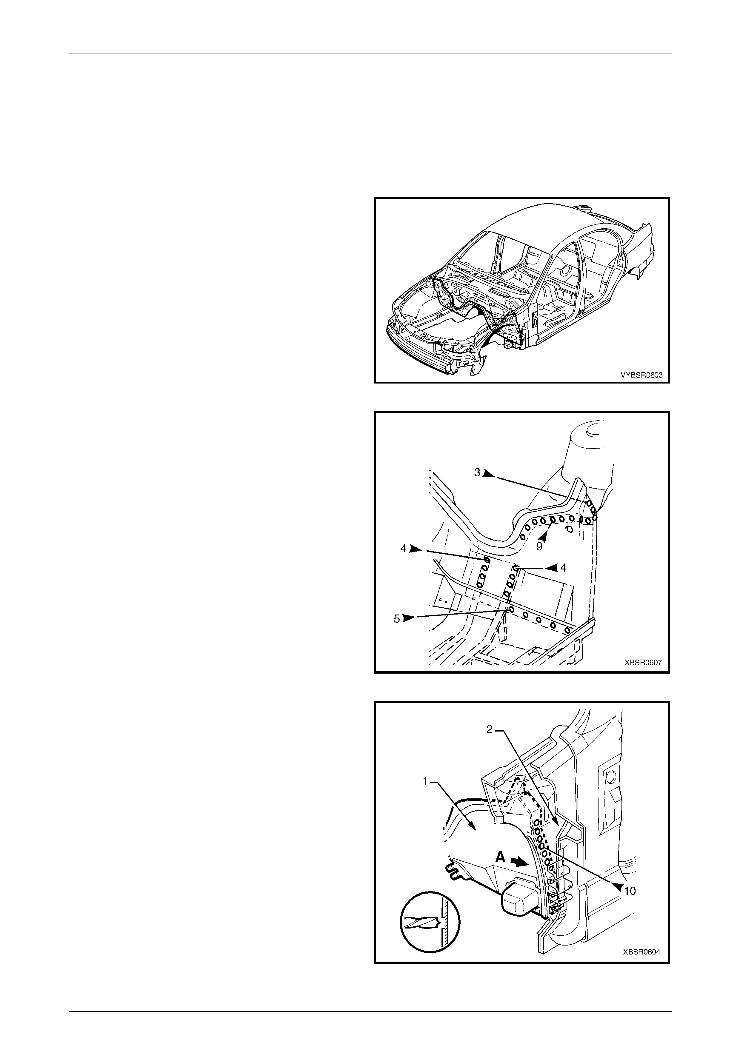
attaching areas. Figure 6A – 3
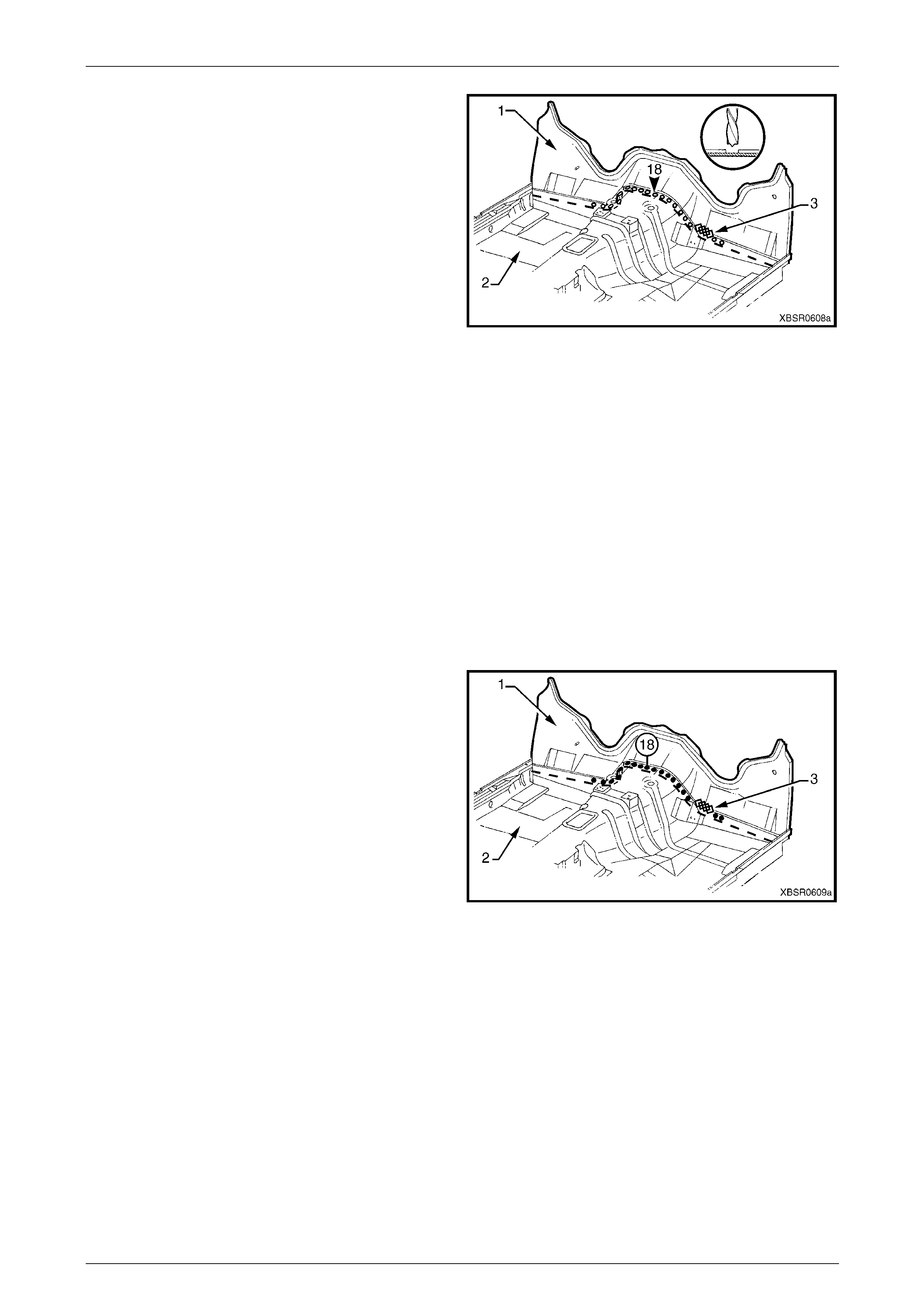
6 Spot cut the welds on each side of the vehicle,
attaching the front floor panel extension to the front
side rail assembly, front wheelhouse panel assembly
and front floor panel assembly.
Figure 6A – 4
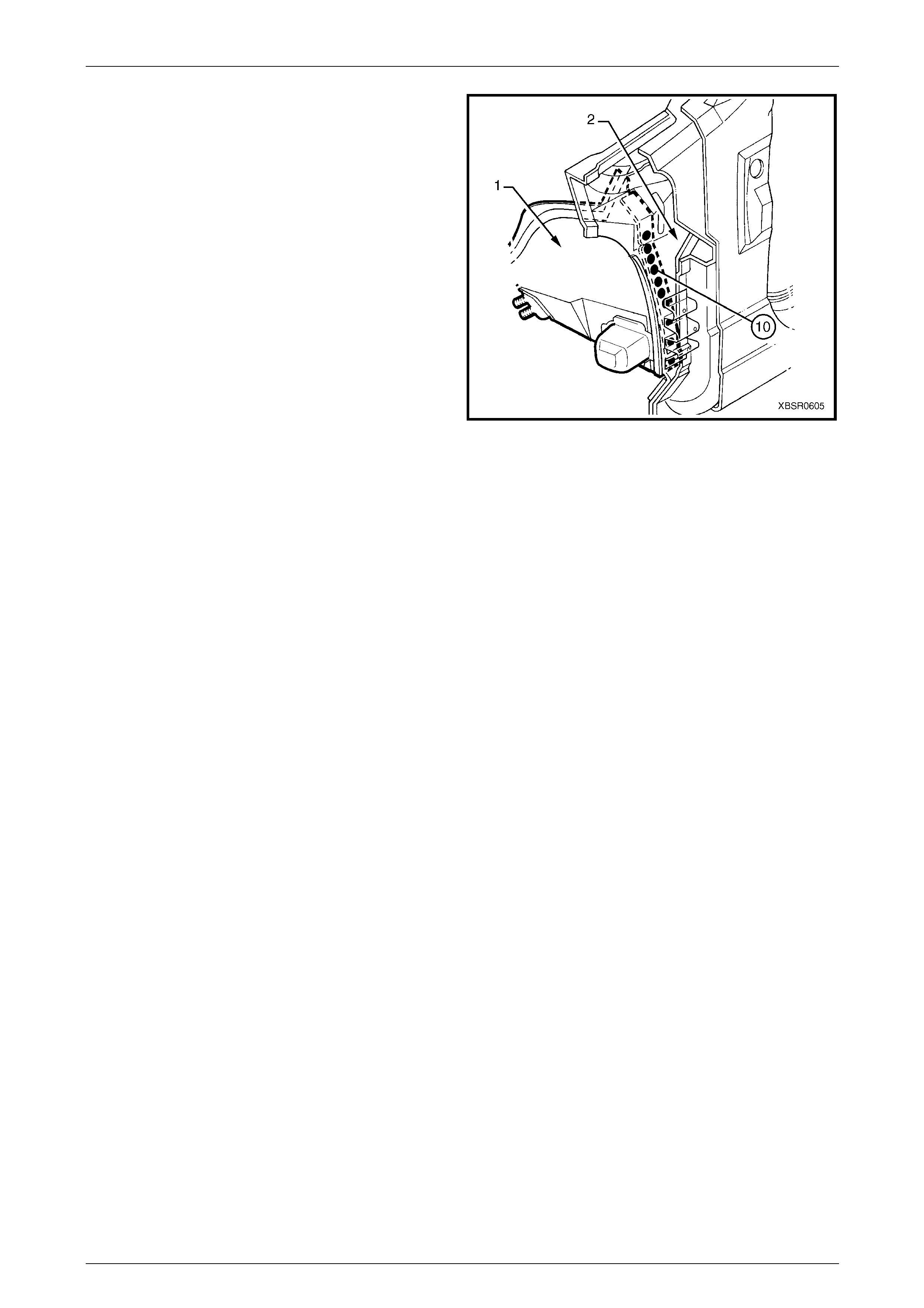
7 Spot cut the welds on each side of the vehicle,
attaching the front floor panel extension (1) to the
hinge pillar inner panel (2) fro m the direction shown A.
Figure 6A – 5
6A Cabin Floor – Sedan, Wagon, Coupe and AWD Wagon Page 6A-5
Page 6A-5
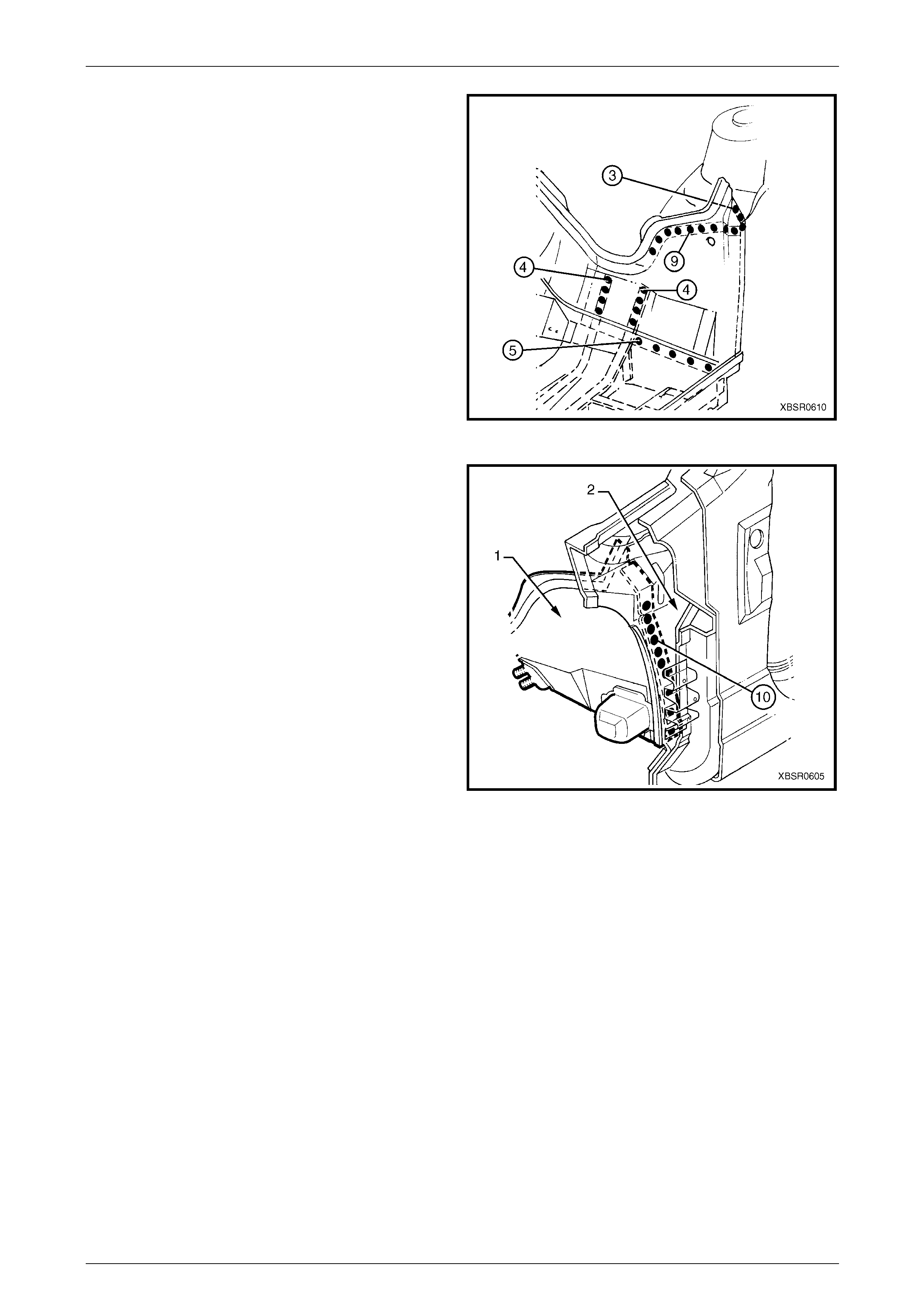
8 Spot cut the welds attaching the front floor panel
extension (1) to the front floor pane l assembly (2).
9 Remove the MIG weld (3) from near the footrest
bracket.
NOTE
Some models may not have this weld.
10 Remove the front floor panel extension from the
vehicle, then repair any damage to adjacent parts as
required.
11 Check and rectify the alignme nt of the bod y as
required, refer to Section 3 Body Construction. Figure 6A – 6
Replace
NOTE
• Spot welding is the preferred method for
attaching of panels and should be used
whenever possible. Where the spot welding
equipment available will not access the
required weld position, a plug weld should be
performed.
• The same number and position of spot welds
(or plug welds) should be used when
replacing the panel, as was used during
manufacture, in order to maintain the original
structural strength of the vehicle.
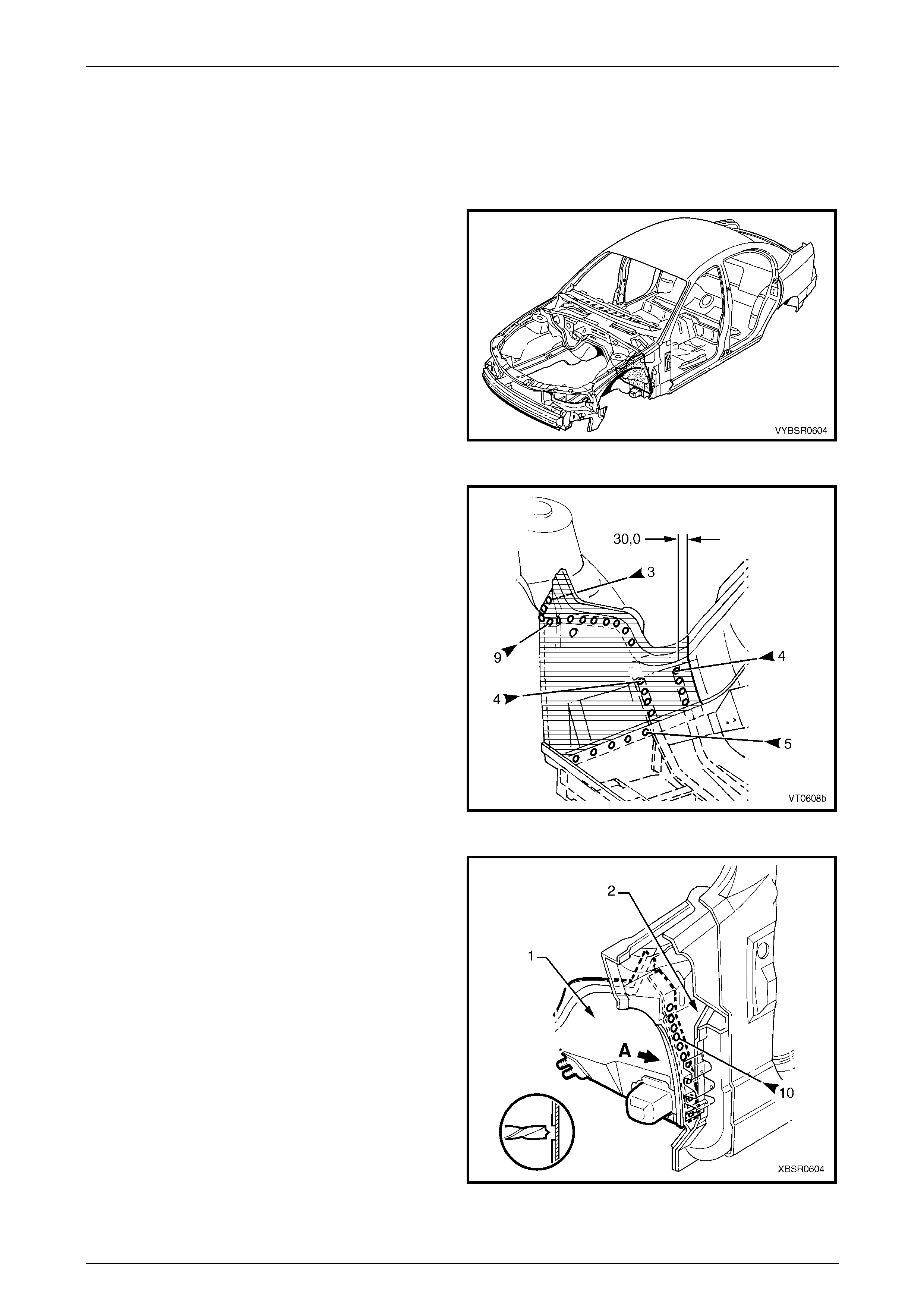
1 As required, mark the new panel with drilling locations in preparation for plug welding. Drill holes as required.
NOTE
The new front floor panel extension (1) may be
plug welded in position from above, utilising the
holes cut in the front floor panel assembly (2)
during removal.
2 Prepare all mating surfaces and treat with Weld
Through Primer (Item 1) as required,
refer to Section 3 Body Construction.
3 Clamp the new panel in position in the vehicle.
4 Plug weld the front floor panel extension to the front
floor panel assembly.
5 Make a MIG weld (3) near the footrest bracket. Figure 6A – 7
6A Cabin Floor – Sedan, Wagon, Coupe and AWD Wagon Page 6A-6
Page 6A-6
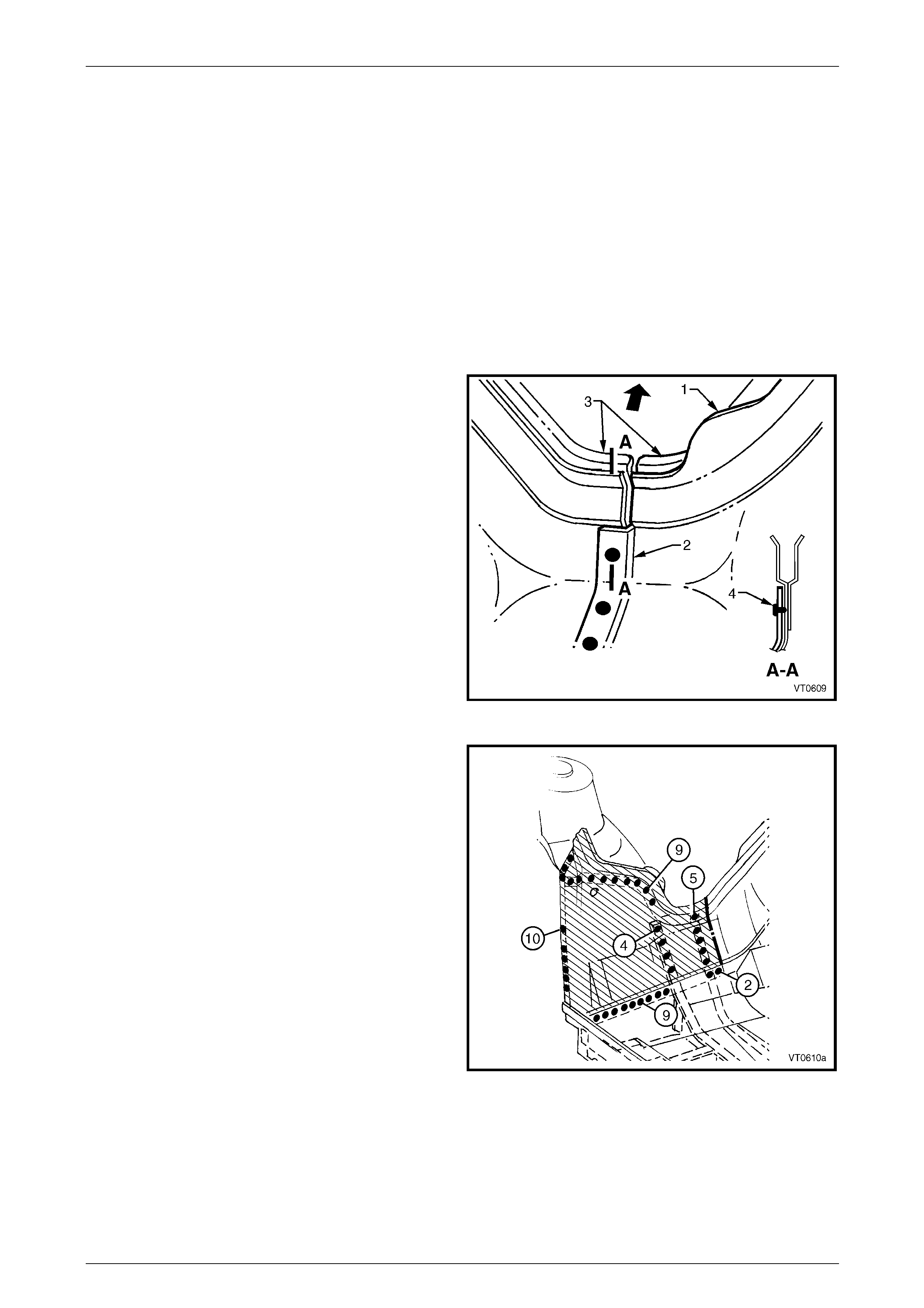
6 On each side of the vehicle, spot or plug weld the front
floor panel extension to the front side rails, front
wheelhouse panel ass embly and front floor panel.
Figure 6A – 8
7 Spot or plug weld the front floor panel extension (1) to
the hinge pillar inner panel (2).
8 Replace any other remov ed panels as required, refer
to the relevant Section in this Supplement.
9 Refinish and paint panels and other components as
required. Refer to Section 3 Body Construction .
10 Apply Joint Sealer (Item 3) as required.
Refer to Section 3 Body Construction.
11 Apply Cavity Wax (Item 8) as required to the inside of
any box sections or areas inaccessible to paint,
refer to Section 3 Body Construction.
12 Apply floor deadeners as required,
refer to Section 3 Body Construction.
13 Replace the dash panel ass embly,
refer to Section 5 Cockpit Module.
14 Reinstall the remaining bolt-on panels and
components as required, refer to the appropriate
Section of the MY2005 VZ Service Information. Figure 6A – 9
6A Cabin Floor – Sedan, Wagon, Coupe and AWD Wagon Page 6A-7
Page 6A-7
2.2 Front Floor Panel Extension – Partial
Replace
Remove
1 Remove the adjacent bolt-on panels a nd components
as described in the appropriate Section of the MY2005
VZ Service Information.
2 Secure the vehicle on a suitable fixture. As a
minimum, support the appropriate structural s ections
of the vehicle on safety stands.
3 Remove the dash panel asse mbly,
refer to Section 5 Cockpit Module.
4 Remove the adjoining panels as required, refer to the
relevant Section in this Supplement.
5 Using a scraper and heat gun, remove the body sealer
and deadener from the front floor and floor extension
attaching areas. Figure 6A – 10
6 Mark the front floor panel extension for cutting as
shown. Cut the panel 30 mm inboard from the front
side rail flange.
7 Spot cut the welds attaching the partial front floor
panel extension to the front side rail assembly, front
wheelhouse panel ass embly and front floor panel
assembly.
Figure 6A – 11
8 Spot cut the welds attaching the front floor panel
extension (1) to the hinge pillar inner panel (2) from
the direction shown A.
9 Remove the partial front floor panel e xtension and
repair any damage to adjacent panels as required.
10 Check and rectify the alignme nt of the bod y as
required, refer to Section 3 Body Construction.
Figure 6A – 12
6A Cabin Floor – Sedan, Wagon, Coupe and AWD Wagon Page 6A-8
Page 6A-8
Replace
NOTE
• Spot welding is the preferred method for
attaching of panels and should be used
whenever possible. Where the spot welding
equipment available will not access the
required weld position, a plug weld should be
performed.
• The same number and position of spot welds
(or plug welds) should be used when
replacing the panel, as was used during
manufacture, in order to maintain the original
structural strength of the vehicle.
1 Accurately cut the required section from a new panel, allowing approximately 15 mm overlap for the lap joint.
2 On the new section, trim the glue track back 15 mm to
allow butting against the section on the vehicle.
3 Flange the new section of front floor panel extensio n
(1) using a suitable tool to for m a joggle (2) to facilitate
the lap joint. The joggle shoul d be towards the interior
of the vehicle.
4 Ensure that the old and new glue tracks (3) align, to
allow installation of the dash panel assembly. The glue
tracks need not be butt welded.
5 As required, mark the new panel with drilling locations
in preparation for plug welding. Drill holes as required.
6 Prepare all mating surfaces and treat with Weld
Through Primer (Item 1) as required,
refer to Section 3 Body Construction.
7 Spot or plug weld (4) the lap joint at a minimum
spacing of 35 mm along the join, then MIG weld along
the engine compartment side of the panels. Figure 6A – 13
8 Spot or plug weld the partial floor panel extension to
the front side rails, front wheelhouse panel assembly
and front floor panel.
Figure 6A – 14
6A Cabin Floor – Sedan, Wagon, Coupe and AWD Wagon Page 6A-9
Page 6A-9
9 Spot or plug weld the front floor panel extension (1) to
the hinge pillar inner panel (2).
10 Replace any other remov ed panels as required, refer
to the relevant Section in this Supplement.
11 Refinish and paint panels and other components as
required. Refer to Section 3 Body Construction .
12 Apply Joint Sealer (Item 3) as required.
Refer to Section 3 Body Construction.
13 Apply Cavity Wax (Item 8) as required to the inside of
any box sections or areas inaccessible to paint,
refer to Section 3 Body Construction.
14 Apply floor deadeners as required,
refer to Section 3 Body Construction.
15 Replace the dash panel ass embly,
refer to Section 5 Cockpit Module.
16 Reinstall the remaining bolt-on panels and
components as required, refer to the appropriate
Section of the MY2005 VZ Service Information. Figure 6A – 15
6A Cabin Floor – Sedan, Wagon, Coupe and AWD Wagon Page 6A-10
Page 6A-10
2.3 Front Floor Panel Assembly – Replace
Care must be taken to avoid cutting the fuel,
brake or emission control pipes.
Remove
1 Remove the adjacent bolt-on panels a nd components
as described in the appropriate Section of the MY2005
VZ Service Information.
2 Remove the adjoining panels as required, refer to the
relevant Section in this Supplement.
3 Secure the vehicle on a suitable fixture. As a
minimum, support the structural sections of the vehicle
on safety stands.
4 Using a scraper and heat gun, remove the body sealer
and deadener from the front floor attaching areas.
5 Spot cut the welds attaching the front floor panel
extension to the front floor panel assembly, refer to
2.1 Front Floor Panel Extension – Replace. Figure 6A – 16
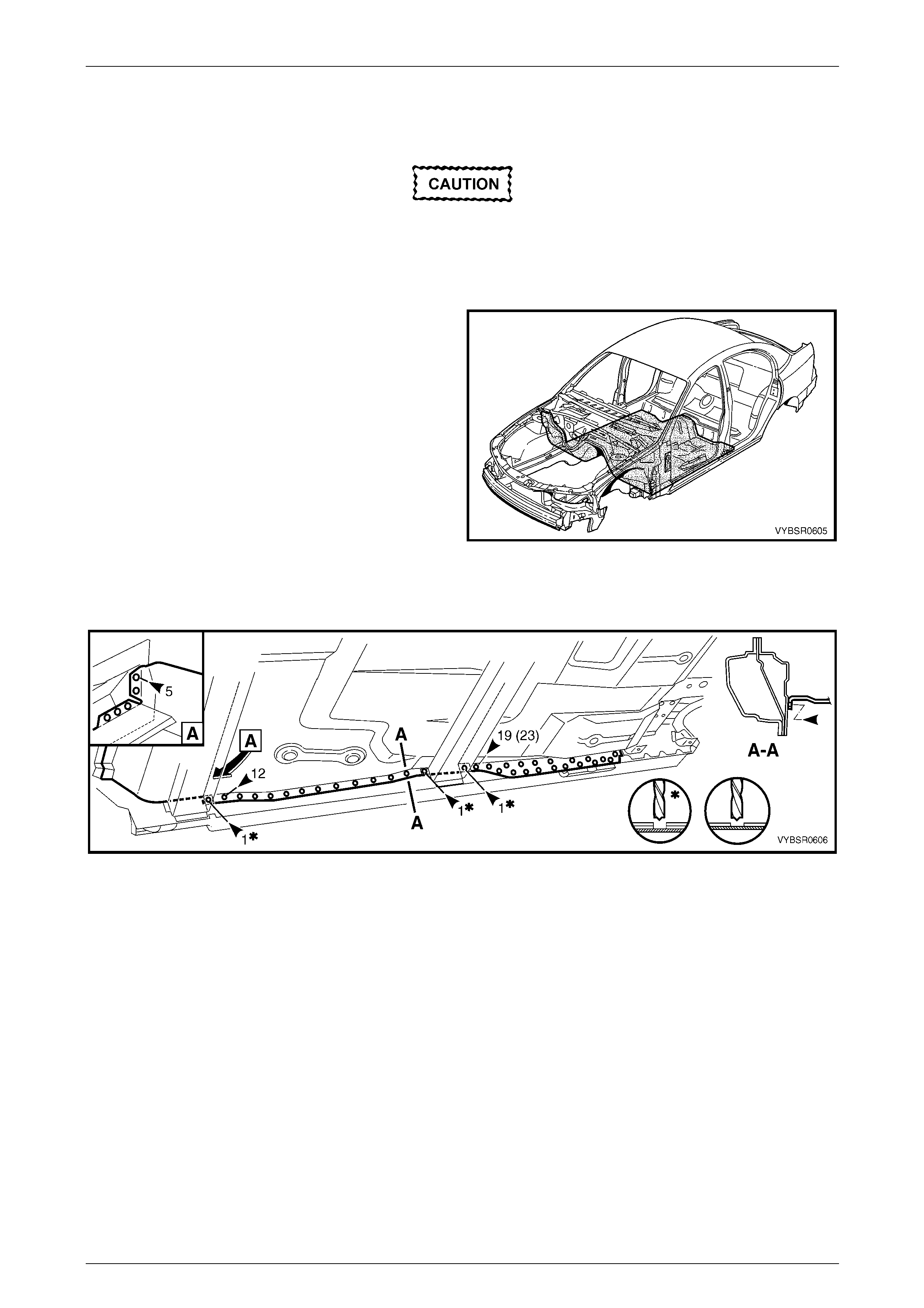
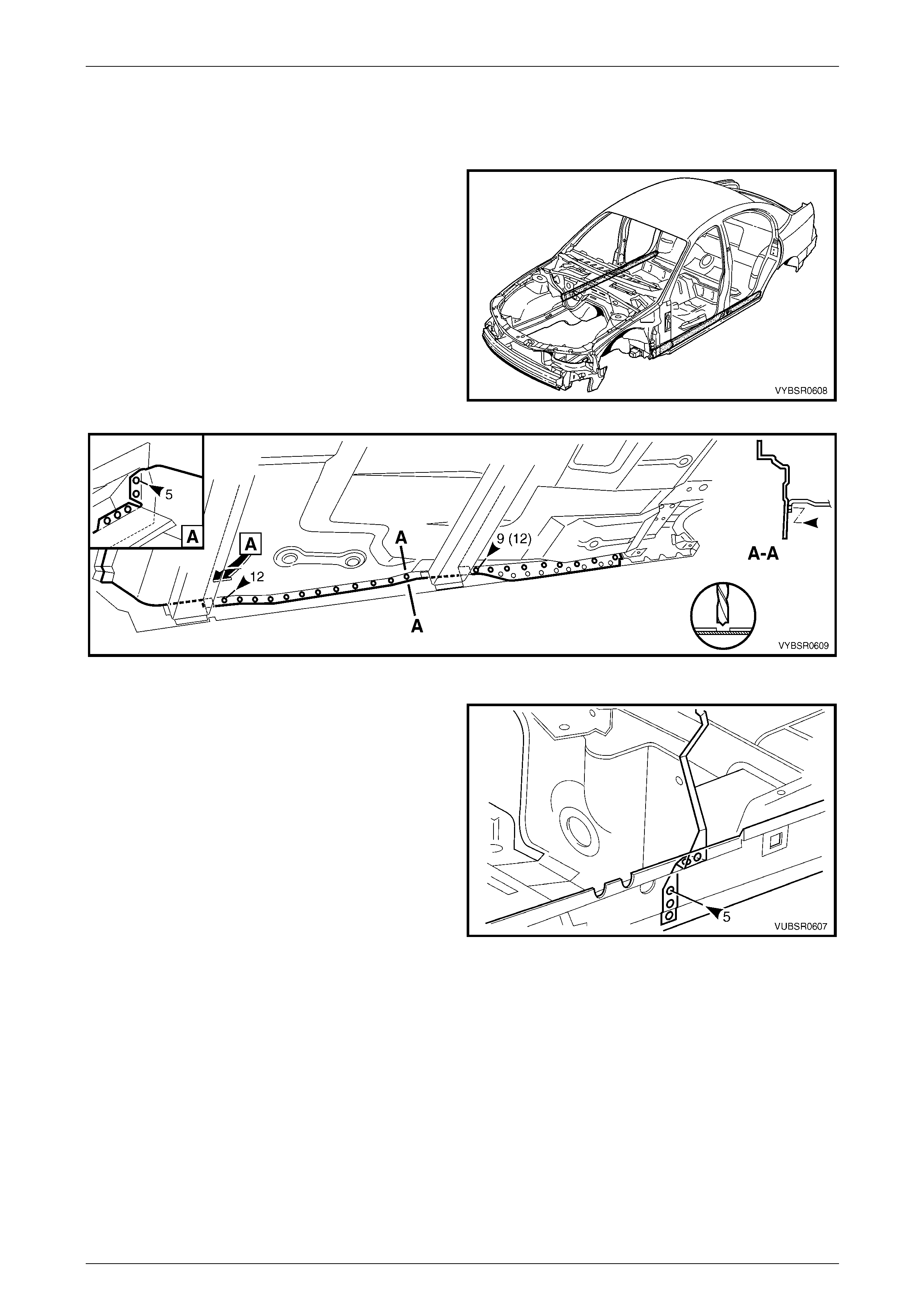
6 From underneath the vehicle, spot cut the welds attaching the front floor panel assembly to the inner rocker panel
assembly, refer to Figure 6A – 17.
Figure 6A – 17
6A Cabin Floor – Sedan, Wagon, Coupe and AWD Wagon Page 6A-11
Page 6A-11
7 From underneath the vehicle, spot cut the welds
attaching the park brake cable bracket to the rear floor
panel assembly.
8 On each side of the vehicle, spot cut the welds
attaching the front floor panel assembly to the front
side rail assemblies, refer to Figure 6A – 19.
Figure 6A – 18
Figure 6A – 19
9 Spot cut the welds attaching the front floor panel
assembly (1) to the rear floor panel assembly (2).
10 Remove the front floor assembly from the vehicle and
repair any damage to adjacent panels as required.
11 Check and rectify the alignme nt of the bod y as
required, refer to Section 3 Body Construction.
Figure 6A – 20
6A Cabin Floor – Sedan, Wagon, Coupe and AWD Wagon Page 6A-12
Page 6A-12
Replace
NOTE
• Spot welding is the preferred method for
attaching of panels and should be used
whenever possible. Where the spot welding
equipment available will not access the
required weld position, a plug weld should be
performed.
• The same number and position of spot welds
(or plug welds) should be used when
replacing the panel, as was used during
manufacture, in order to maintain the original
structural strength of the vehicle.
1 As required, mark the new panel with drilling locations in preparation for plug welding. Drill holes as required.
2 Prepare all mating surfaces and treat with Weld Through Primer (Item 1) as requir ed,
refer to Section 3 Body Construction.
3 Secure the front floor panel assembly (1) in position
and make several tack welds around its
circumference. Plug weld to the rear floor panel
assembly (2).
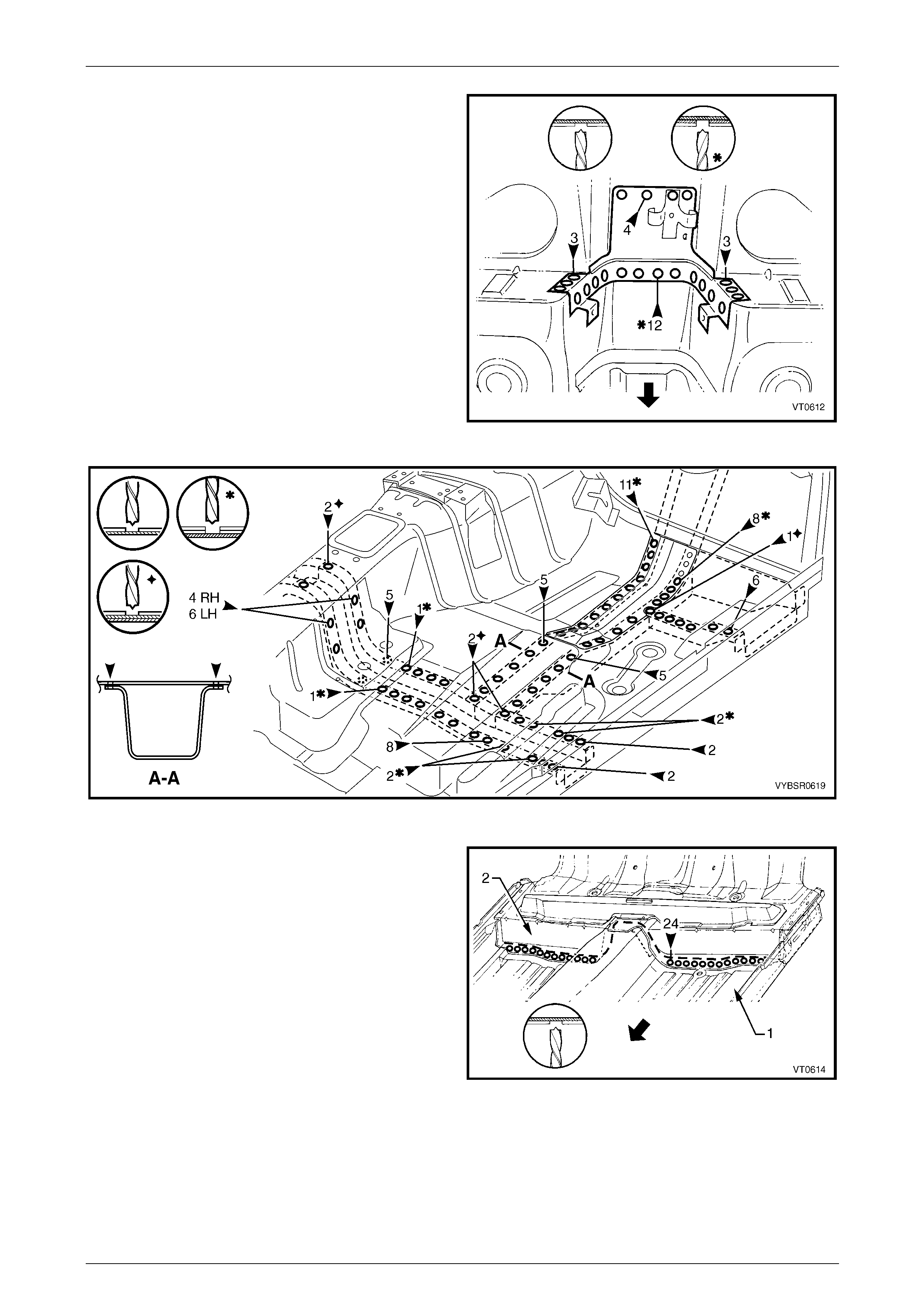
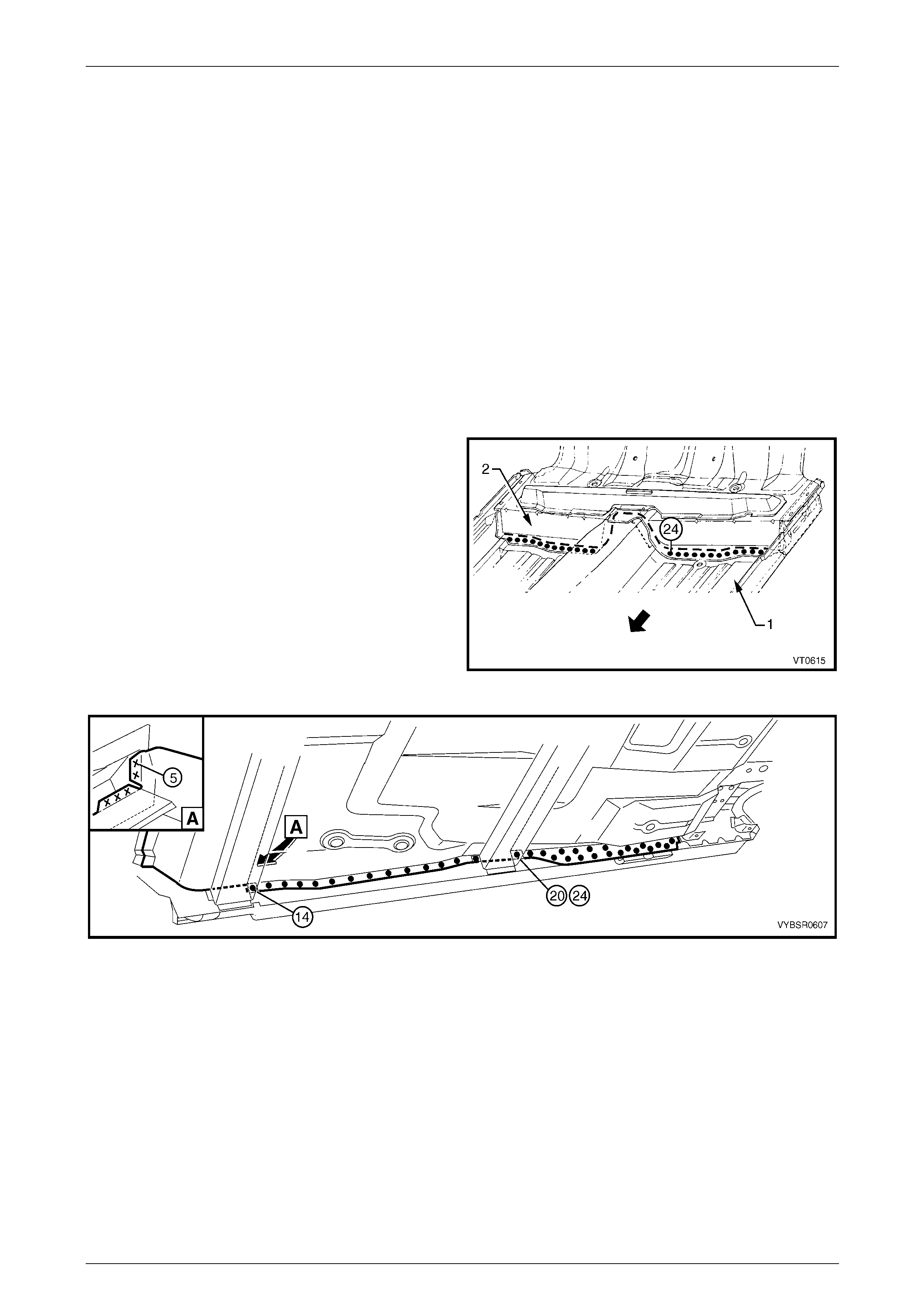
4 From underneath the vehicle, spot or plug weld the
front floor assembly to the inner rocker panel
assembly, 14 places forward of the crossmember and
20 places for Sedan and Coupe vehicles or 24 places
for Wagon vehicles rear of the crossmember. F r om
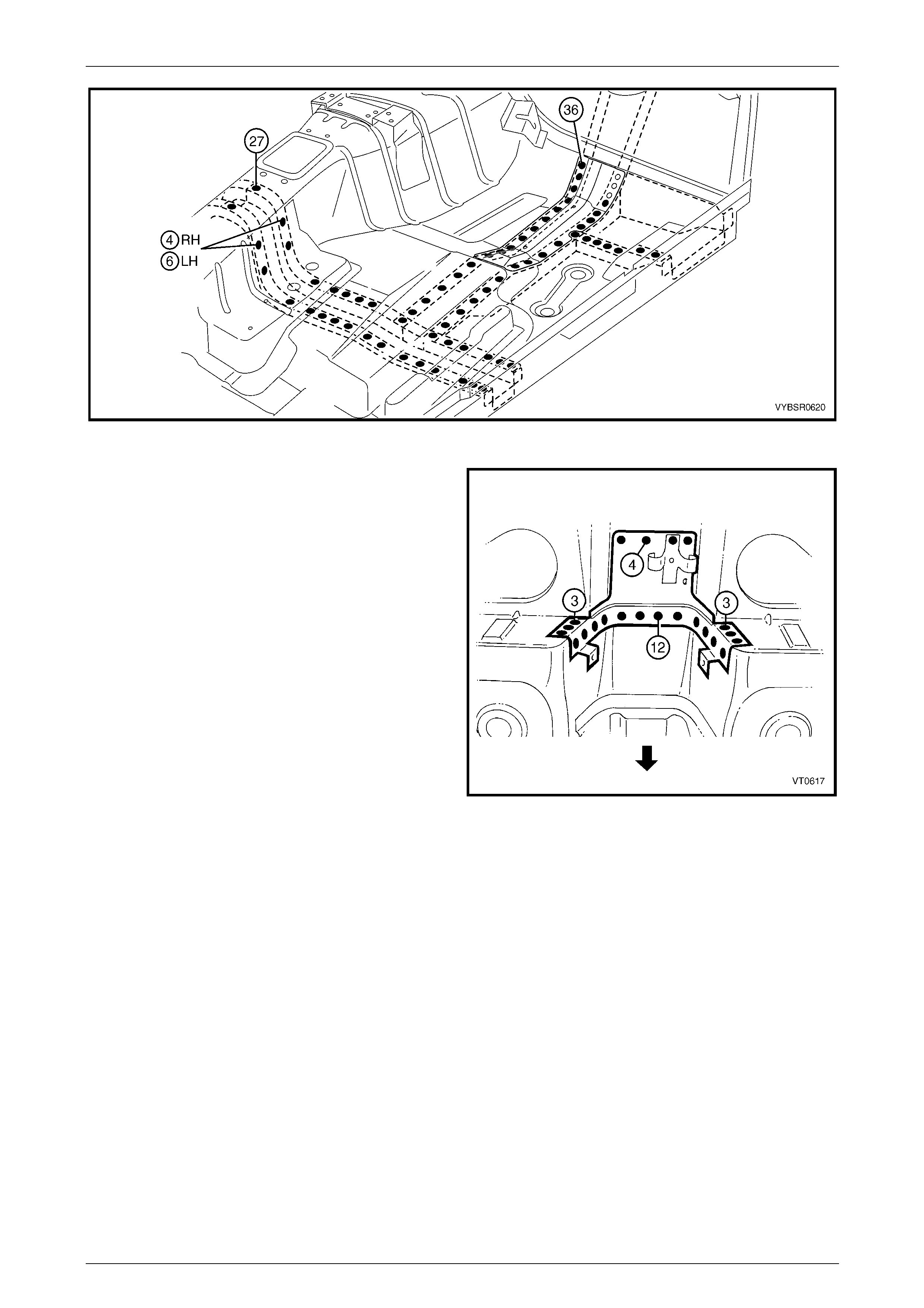
inside the vehicle, also spot weld, five places, refer to
Figure 6A – 22.
Figure 6A – 21
Figure 6A – 22
5 Replace the front floor panel extension, or weld the extension to the front floor panel assembly,
refer to 2.1 Front Floor Panel Extension – Replace.
6 On each side of the vehicle, plug weld the front floor panel assembly to the front side rail assemblies,
refer to Figure 6A – 23.
6A Cabin Floor – Sedan, Wagon, Coupe and AWD Wagon Page 6A-13
Page 6A-13
Figure 6A – 23
7 Reinstall the park brake cable bracket to the rear floor
panel assembly.
8 Replace any other remov ed panels as required, refer
to the relevant Section in this Supplement.
9 Refinish and paint panels and other components as
required. Refer to Section 3 Body Construction .
10 Apply Joint Sealer (Item 3) as required.
Refer to Section 3 Body Construction.
11 Apply Cavity Wax (Item 8) as required to the inside of
any box sections or areas inaccessible to paint,
refer to Section 3 Body Construction.
12 Apply floor deadeners as required,
refer to Section 3 Body Construction.
13 Apply Spray-on dea dener (Item 7) as required to the
underside of the floor,
refer to Section 3 Body Construction.
14 Apply fusible reinforcement patches,
refer to Section 3 Body Construction.
15 Reinstall the remaining bolt-on panels and
components as required, refer to the appropriate
Section of the MY2005 VZ Service Information.
Figure 6A – 24
6A Cabin Floor – Sedan, Wagon, Coupe and AWD Wagon Page 6A-14
Page 6A-14
2.4 Inner Rocker Panel Assembly – Replace
Remove
1 Remove the adjacent bolt-on panels a nd components
as described in the appropriate Section of the MY2005
VZ Service Information.
2 Secure the vehicle on a suitable fixture. As a
minimum, support the structural sections of the vehicle
on safety stands.
3 Remove the adjacent panels as required, refer to the
relevant Section in this Supplement.
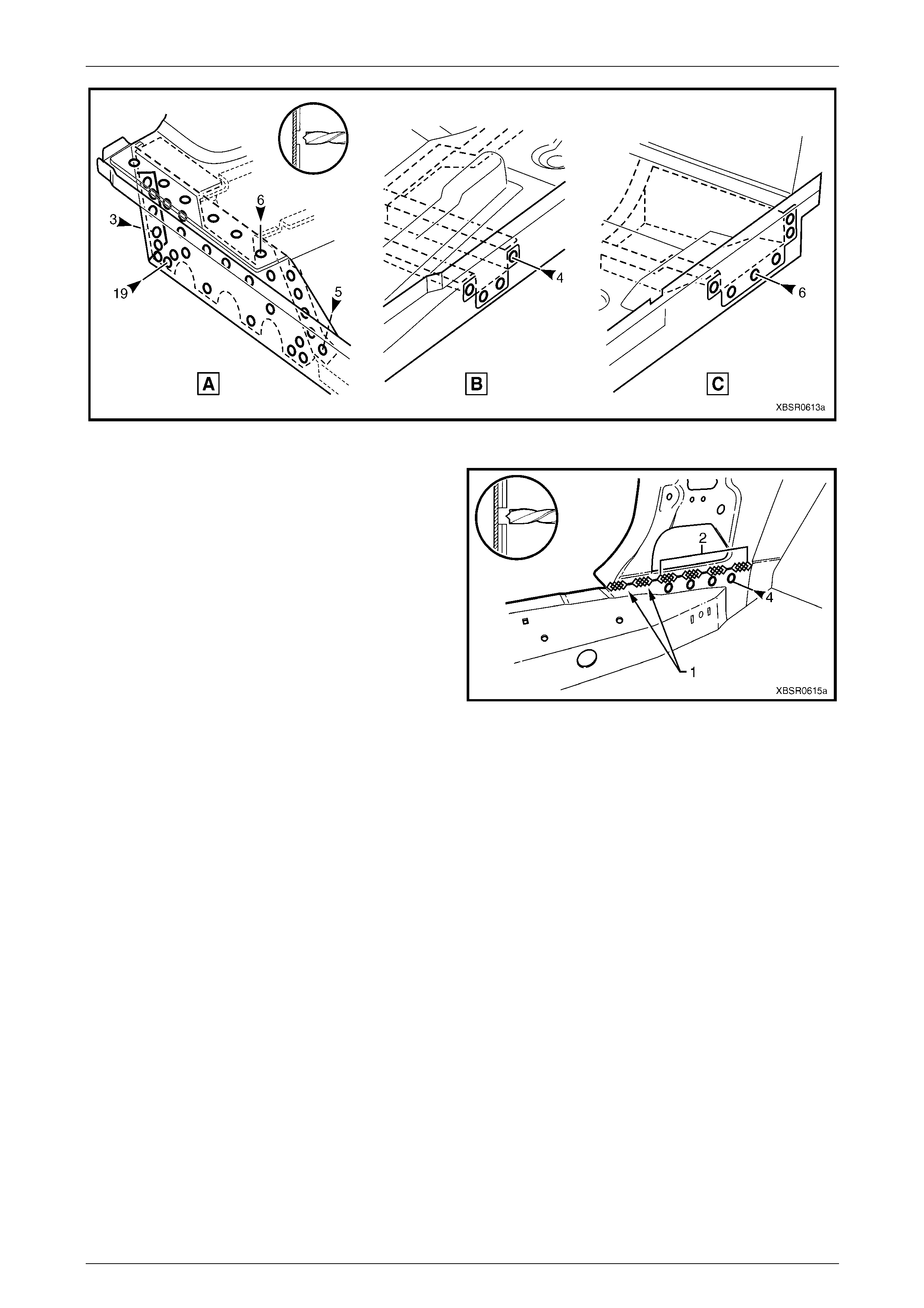
4 Spot cut the welds attaching the front floor panel
assembly to the inner rocker panel as required.
Refer to Figure 6A – 26.
Figure 6A – 25
Figure 6A – 26
5 Spot cut the welds attaching the inner rocker panel
assembly to the rear floor panel outer extension (A),
centre crossmember (B), and front floor panel support
(C), refer to Figure 6A – 28.
Figure 6A – 27
6A Cabin Floor – Sedan, Wagon, Coupe and AWD Wagon Page 6A-15
Page 6A-15
Figure 6A – 28
6 Remove the two MIG welds (1) attaching the inner
rocker panel to the hinge pillar inner assembly.
7 If not already done so, remove the four spot welds, or
for some models four MIG welds (2), attaching the
inner rocker panel to the hinge pillar in ner assembly
and rocker panel reinforcement.
8 Remove the inner rocker panel from the vehicle and
repair any damage to adjacent panels as required.
9 Check and rectify the alignme nt of the bod y as
required, refer to Section 3 Body Construction.
Figure 6A – 29
Replace
NOTE
• Spot welding is the preferred method for
attaching of panels and should be used
whenever possible. Where the spot welding
equipment available will not access the
required weld position, a plug weld should be
performed.
• The same number and position of spot welds
(or plug welds) should be used when
replacing the panel, as was used during
manufacture, in order to maintain the original
structural strength of the vehicle.
1 As required, mark the new panel with drilling locations in preparation for plug welding. Drill holes as required.
2 Prepare all mating surfaces and treat with Weld Through Primer (Item 1) as requir ed,
refer to Section 3 Body Construction.
3 Clamp the inner rocker panel in positi on, noting to ensure it fits behind the hinge pillar inn er assemb ly.
6A Cabin Floor – Sedan, Wagon, Coupe and AWD Wagon Page 6A-16
Page 6A-16
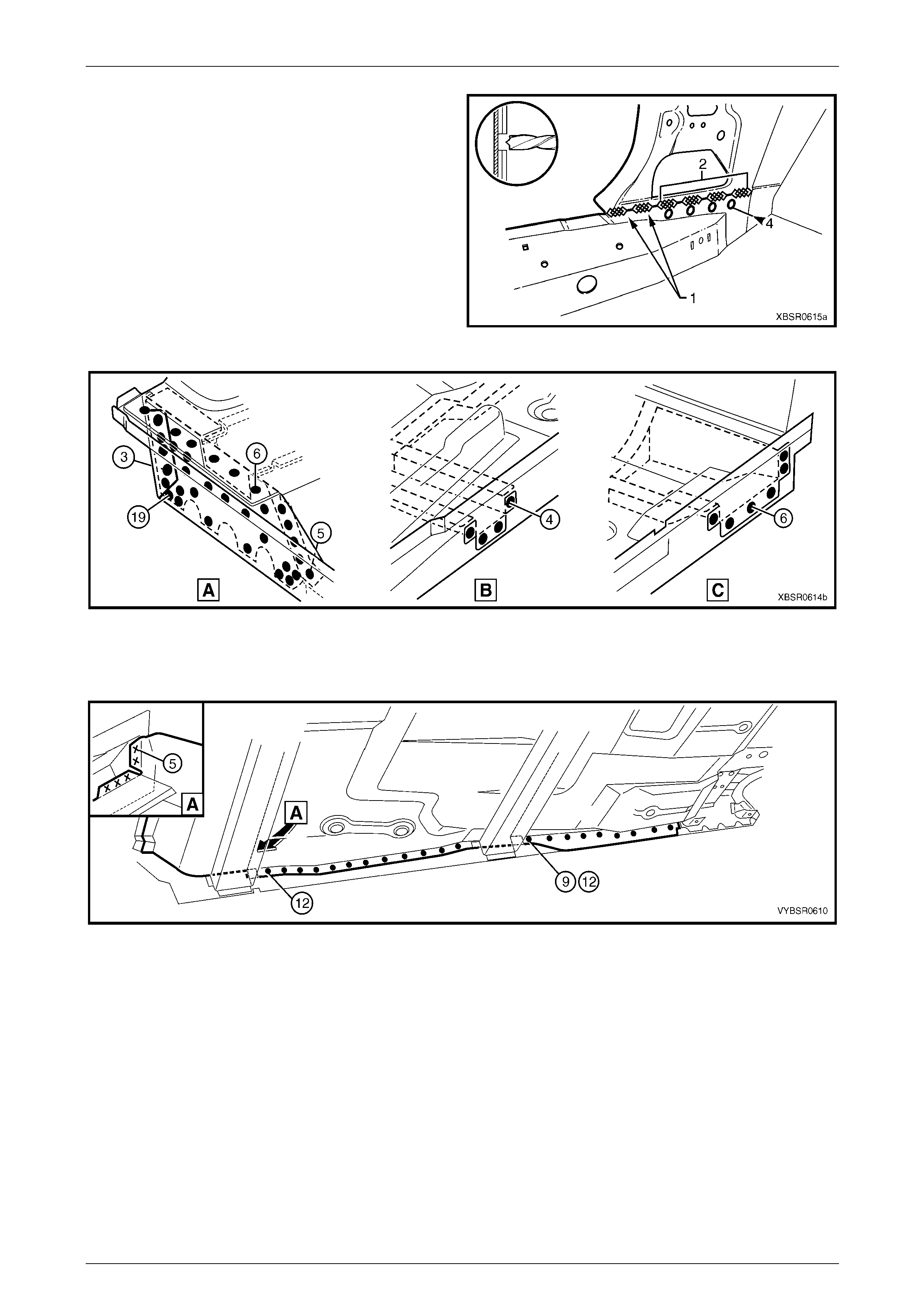
4 Make two MIG welds (1) and if removed, four MIG
welds (2), to attach inner rocker panel to the hinge
pillar inner assembly.
NOTE
If removed, the four plug welds are to be made
once the door opening frame assembly is
installed.
5 Plug weld the inner rocker pa nel to the rear floor panel
outer extension (A), centre crossmember (B) and front
floor panel support (C), refer Figure 6A – 31 .
Figure 6A – 30
Figure 6A – 31
6 Spot or plug weld the front floor panel assembly to the inner rocker panel, undern eath and inside,
refer to Figure 6A – 32.
Figure 6A – 32
7 Replace the adjoining removed panels as required, refer to the relevant Section in this Supplement.
8 Refinish and paint panels and other components as required. Refer to Section 3 Body Construction.
9 Apply Joint Sealer (Item 3) as required. Refer to Section 3 Body Construction.
10 Apply Cavity Wax (Item 8) as required to the inside of any box secti ons or areas inaccessible to paint,
refer to Section 3 Body Construction.
11 Reinstall the remaining bolt-on panels and components as required, refer to the appropriate Section of the MY2005
VZ Service Information.
6A Cabin Floor – Sedan, Wagon, Coupe and AWD Wagon Page 6A-17
Page 6A-17
2.5 Right-hand Transmission Support
Bracket – Replace
Remove
1 Remove the adjacent bolt-on panels and components as described in the appropriate Section of the MY2005 VZ
Service Information.
2 Using a scraper and heat gun, remove the body sealer and deadener from the front floor attaching areas.
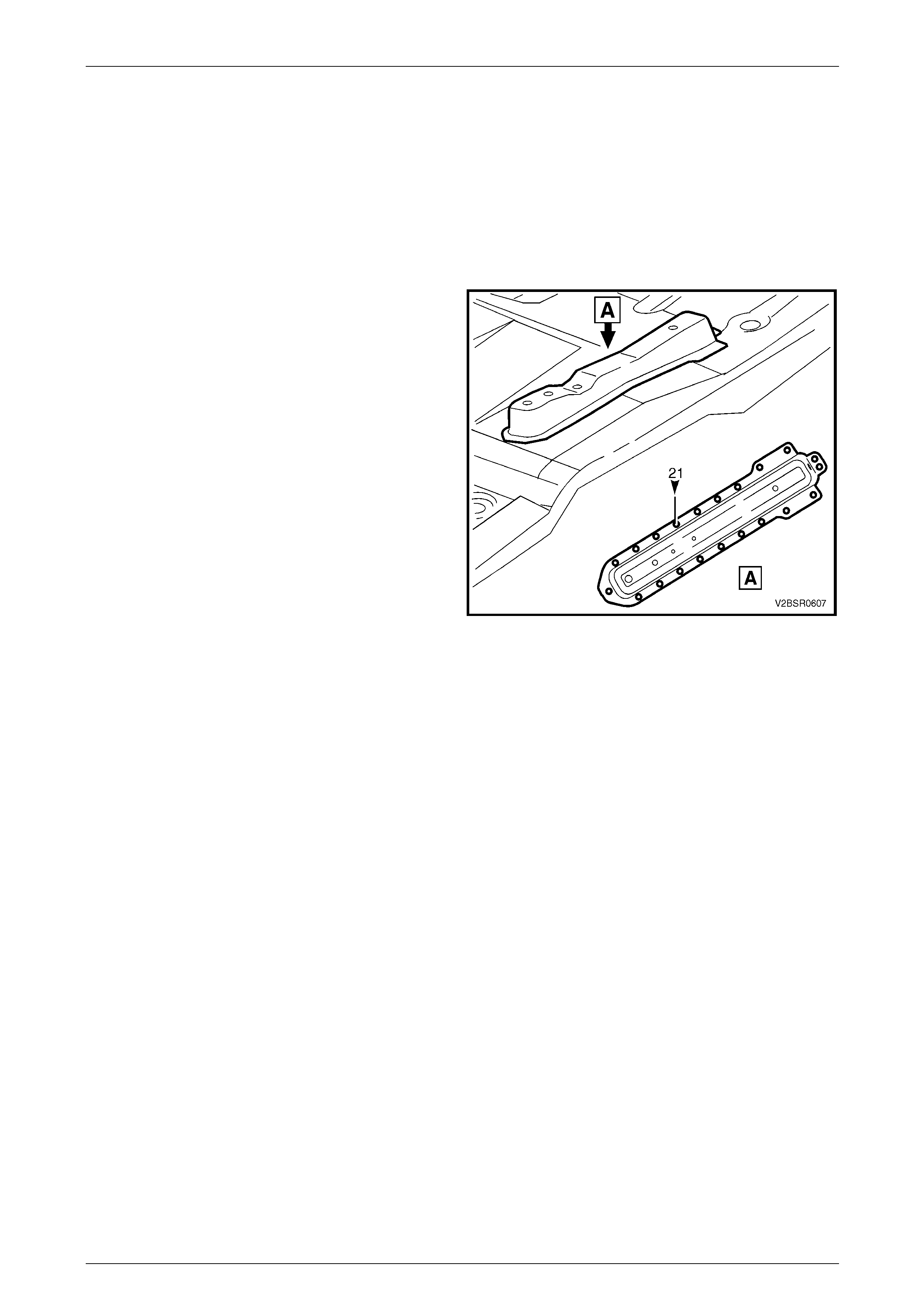
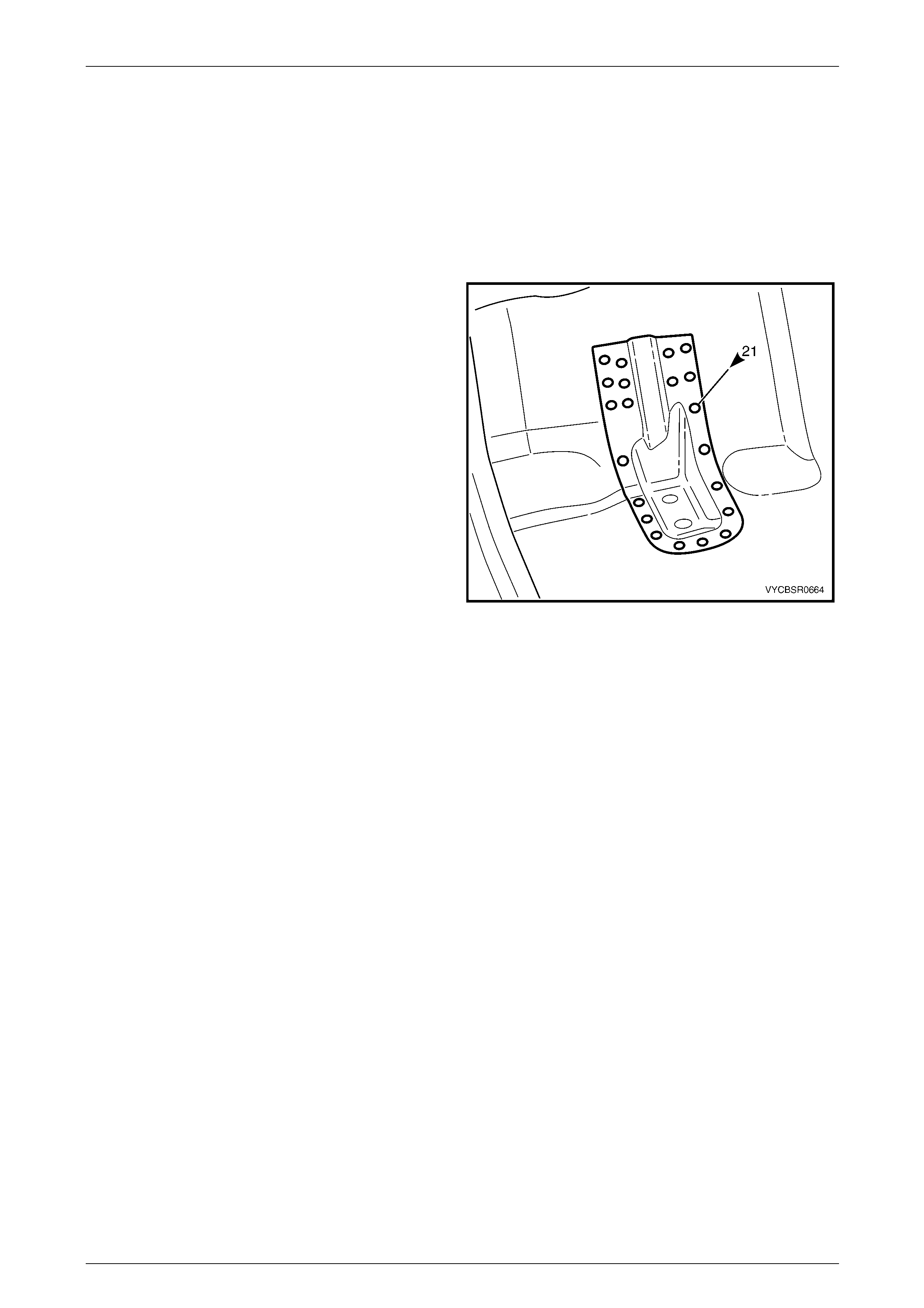
3 Spot cut the 18 welds for the right-hand side or 23 welds for the left-hand side attaching the transmissi on support
bracket to the front floor panel assembly as required, refer to Figure 6A – 33.
4 Remove the transmission support bracket from the vehicle and repair an y damage to the adjacent area as
required.
Figure 6A – 33
Replace
NOTE
• Spot welding is the preferred method for
attaching of panels and should be used
whenever possible. Where the spot welding
equipment available will not access the
required weld position, a plug weld should be
performed.
• The same number and position of spot welds
(or plug welds) should be used when
replacing the panel, as was used during
manufacture, in order to maintain the original
structural strength of the vehicle.
1 As required, mark the new panel with drilling locations in preparation for plug welding. Drill holes as required.
2 Prepare all mating surfaces and treat with Weld Through Primer (Item 1) as requir ed,
refer to Section 3 Body Construction.
NOTE
Positioning of the transmission support brac ket is
critical to driveline orientation. Incorrect location
can cause driveline vibrations.
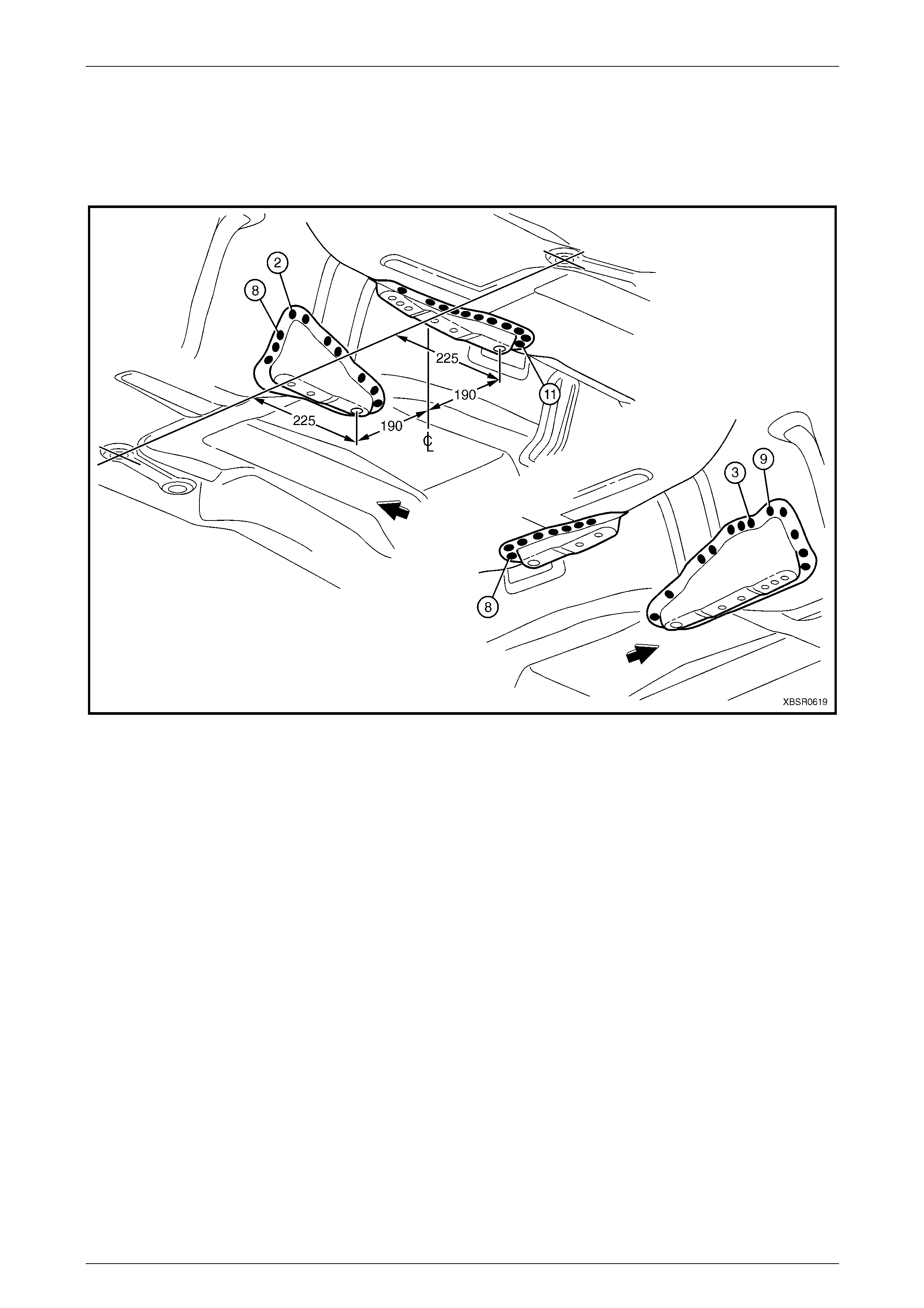
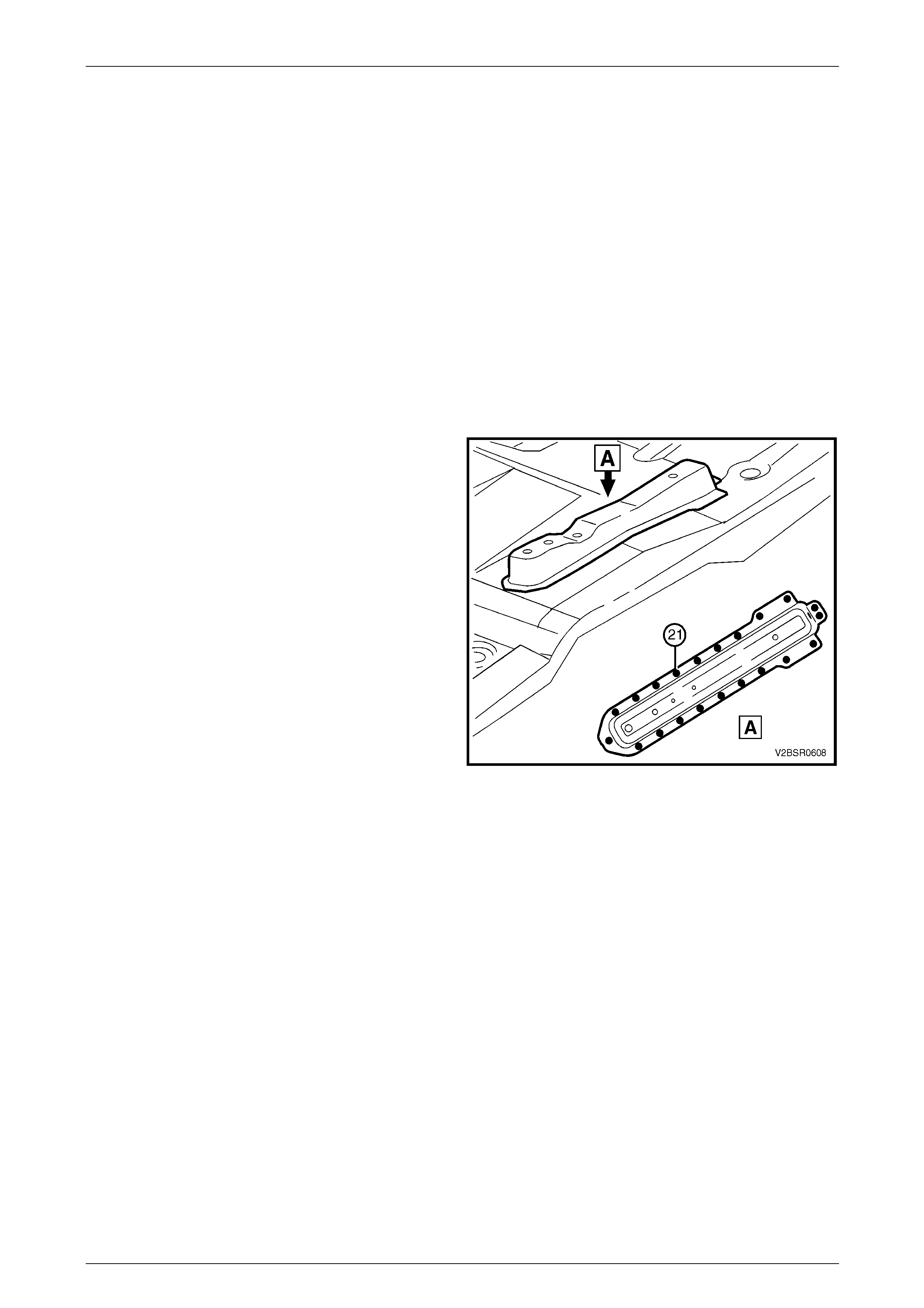
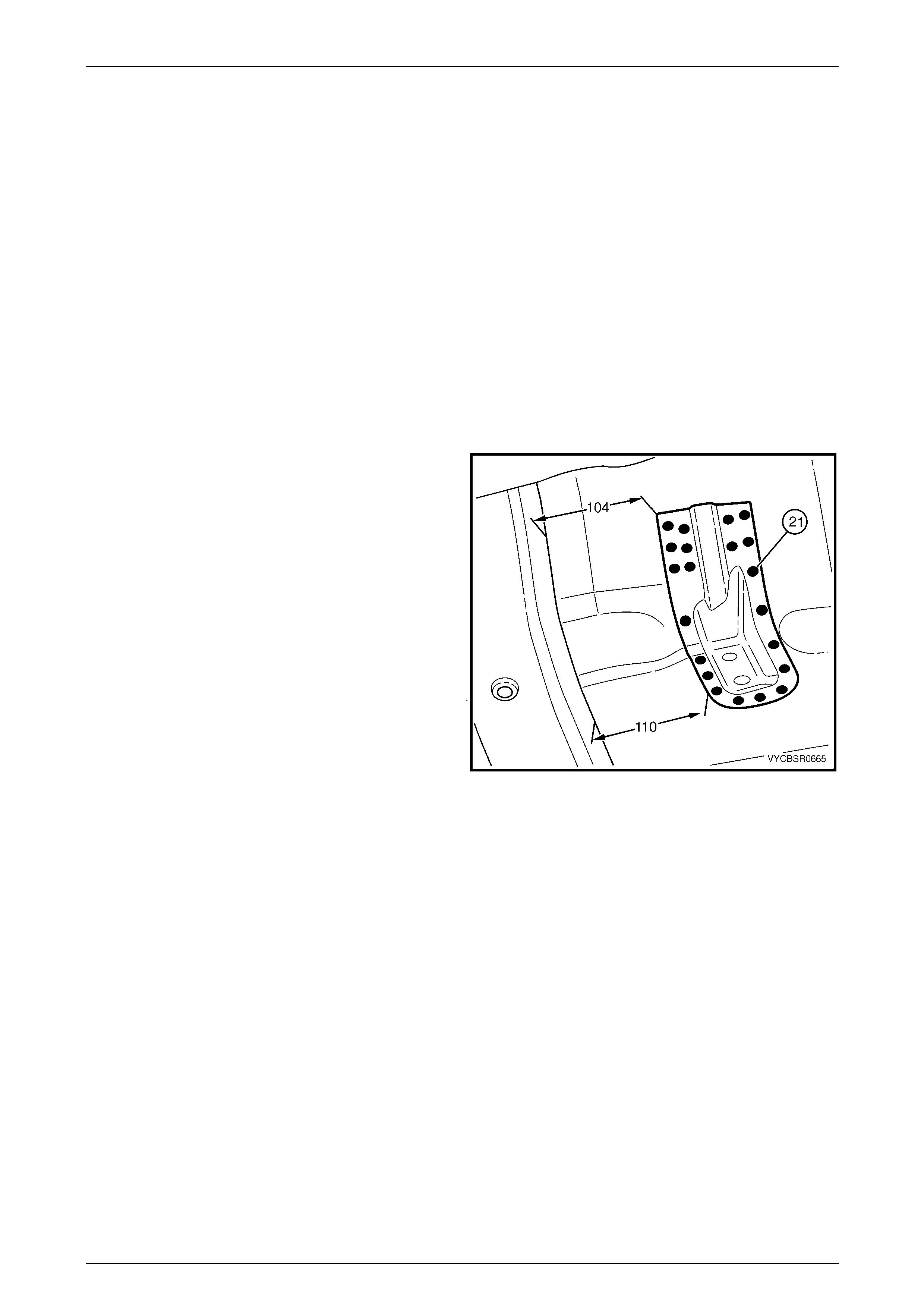
3 Position the transmission support bracket so that the rear tooling hole centre is 190 mm from the vehicle centre and
225 mm rearward of the datum hole centres in the floor, refer to Figure 6A – 24.
6A Cabin Floor – Sedan, Wagon, Coupe and AWD Wagon Page 6A-18
Page 6A-18
4 Temporarily bolt the transmission crossmember in position to help locate the mount. Check the crossmember for
correct orientation to the vehicle.
5 Clamp or tack weld the mount in position and recheck positioning.
6 Spot or plug weld the mount assembl y to the floor, 18 places for the right-han d side or 22 places for the left-hand
side, refer to Figure 6A – 24.
Figure 6A – 34
7 Refinish and paint panels and other components as required. Refer to Section 3 Body Construction.
8 Apply Joint Sealer (Item 3) as required. Refer to Section 3 Body Construction.
9 Apply Cavity Wax (Item 8) as required to the inside of any box secti ons or areas inaccessible to paint,
refer to Section 3 Body Construction.
10 Apply floor deadeners as req uired, refer to Section 3 Body Construction.
11 Apply Spray-on dea dener (Item 7) as required to the underside of the floor, refer to Section 3 Body Construction.
12 Reinstall the remaining bolt-on panels and components as required, refer to the appropriate Section of the MY2005
VZ Service Information.
6A Cabin Floor – Sedan, Wagon, Coupe and AWD Wagon Page 6A-19
Page 6A-19
2.6 Seat Inner Bracket Assembly – Replace
Remove
1 Remove the adjacent bolt-on panels and components as described in the appropriate Section of the MY2005 VZ
Service Information.
2 As required, use a scraper and heat g un to remove the body sealer and deadener from the front floor and floor
extension attachin g areas.
3 Lower the transmission rear mount and propeller shaft centre bearing assembly to avoid damage from heat, refer to
the appropriate section of the MY2005 VZ Service Information.
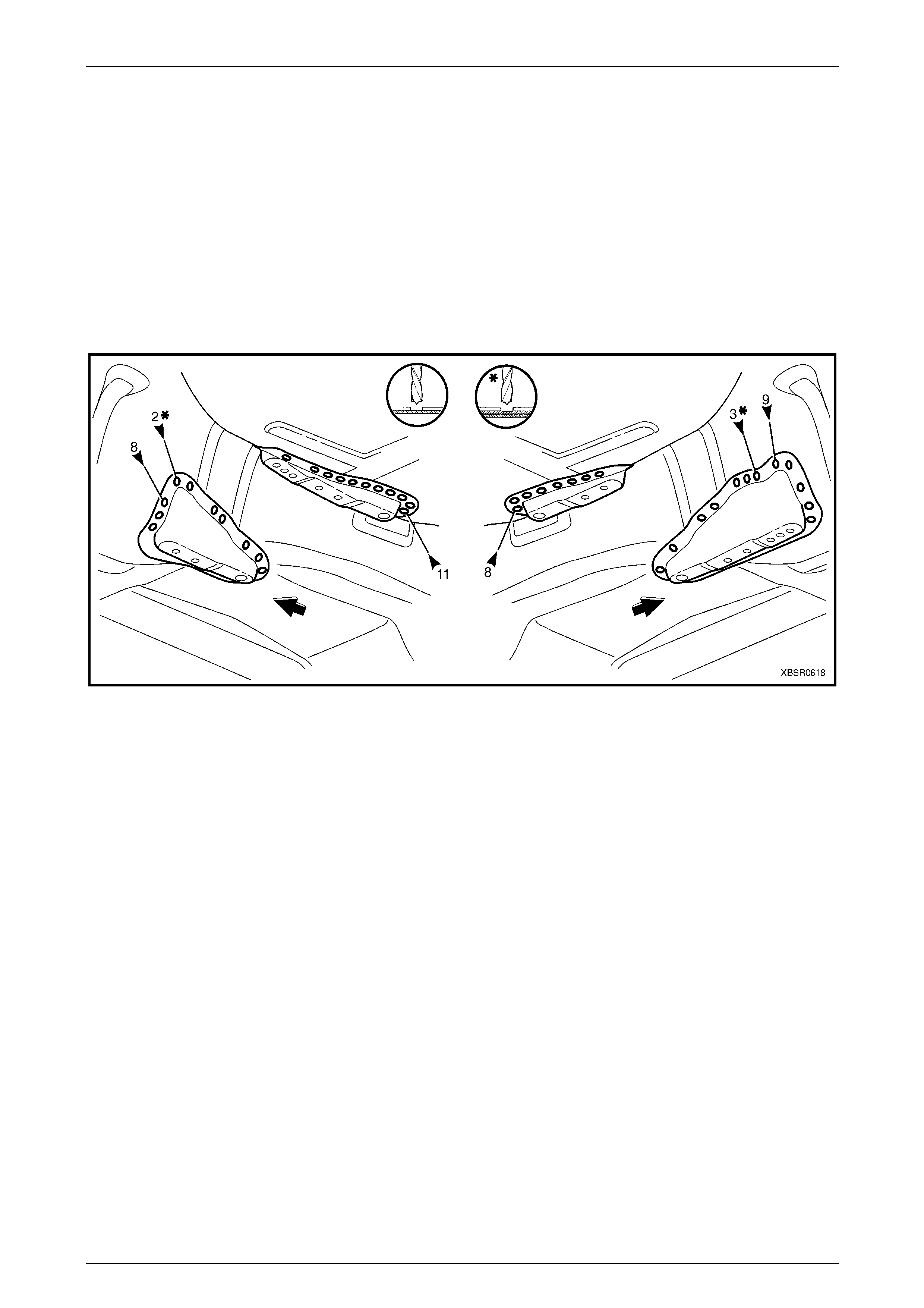
4 Spot cut the 39 welds each side attaching the seat
inner bracket assembly to the floor.
5 Spot cut the four welds each side attaching the
bracket assembly to the floor and propeller shaft
hanger assembly.
6 Spot cut the two welds front and rear attaching the top
of the bracket assembly to the floor.
7 Spot cut the weld attaching the right-hand side of the
bracket assembly to the floor.
8 Remove the bracket assembly from the vehicle and
repair any damage to the adjacent area as required.
Figure 6A – 35
6A Cabin Floor – Sedan, Wagon, Coupe and AWD Wagon Page 6A-20
Page 6A-20
Replace
NOTE
• Spot welding is the preferred method for
attaching of panels and should be used
whenever possible. Where the spot welding
equipment available will not access the
required weld position, a plug weld should be
performed.
• The same number and position of spot welds
(or plug welds) should be used when
replacing the panel, as was used during
manufacture, in order to maintain the original
structural strength of the vehicle.
1 As required, mark the new panel with drilling locations in preparation for plug welding. Drill holes as required.
2 Prepare all mating surfaces and treat with Weld Through Primer (Item 1) as required,
refer to Section 3 Body Construction.
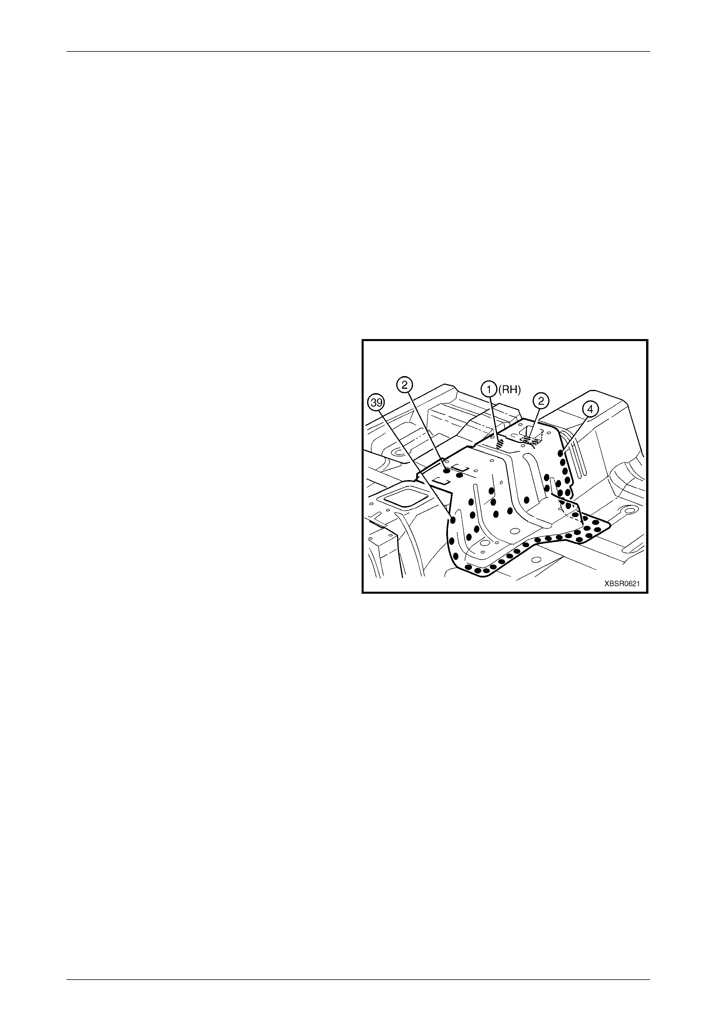
3 Install the seat inner bracket assembly in position and
check that the seat mount holes will align with the
seat.
4 Spot or plug weld the bracket assembl y to the floor
(and propeller shaft hanger assembly if required) as
shown.
5 Refinish and paint panels and other components as
required. Refer to Section 3 Body Construction .
6 Apply floor deadeners as required,
refer to Section 3 Body Construction.
7 Reinstall the transmission re ar mount, refer to
Section 7 Manual Transmissi on or
Section 7 Automatic Transmission i n the MY200 5 VZ
Service Information.
8 Reinstall the propeller sh aft centre bearing assembly,
refer to Section 4C1 Rear Propeller Shaft and
Universal Joint in the MY2005 VZ Service Information.
9 Reinstall the remaining b olt-on panels and
components as required, refer to the appropriate
Section of the MY2005 VZ Service Information.
Figure 6A – 36
6A Cabin Floor – Sedan, Wagon, Coupe and AWD Wagon Page 6A-21
Page 6A-21
2.7 Seat Outer Bracket Assembly – Replace
Remove
1 Remove the adjacent bolt-on panels and components as described in the appropriate Section of the MY2005 VZ
Service Information.
2 Using a scraper and heat gun, remove the body sealer and deadener from the front floor attaching areas.
3 From the underside of the floor, remove deadener in the area of the reinforcement.
4 Spot cut the 21 welds attaching the seat outer bracket
assembly to the floor.
5 Remove the bracket assembly from the vehicle and
repair any damage to the adjacent area as required.
Figure 6A – 37
6A Cabin Floor – Sedan, Wagon, Coupe and AWD Wagon Page 6A-22
Page 6A-22
Replace
NOTE
• Spot welding is the preferred method for
attaching of panels and should be used
whenever possible. Where the spot welding
equipment available will not access the
required weld position, a plug weld should be
performed.
• The same number and position of spot welds
(or plug welds) should be used when
replacing the panel, as was used during
manufacture, in order to maintain the original
structural strength of the vehicle.
1 As required, mark the new panel with drilling locations in preparation for plug welding. Drill holes as required.
2 Prepare all mating surfaces and treat with Weld Through Primer (Item 1) as requir ed,
refer to Section 3 Body Construction.
3 Install the seat outer bracket assembly in position and
check that the seat mount holes will align with the
seat.
4 Spot or plug weld the bracket assembl y to the floor,
21 places as shown.
5 Refinish and paint panels and other components as
required. Refer to Section 3 Body Construction .
6 Apply Spray-on dea dener (Item 7) as required to the
underside of the floor,
refer to Section 3 Body Construction.
7 Apply floor deadeners as required,
refer to Section 3 Body Construction.
8 Reinstall the remaining b olt-on panels and
components as required, refer to the appropriate
Section of the MY2005 VZ Service Information.
Figure 6A – 38
6A Cabin Floor – Sedan, Wagon, Coupe and AWD Wagon Page 6A-23
Page 6A-23
2.8 Propeller Shaft Hanger Assembly –
Replace
Remove
1 Remove the adjacent bolt-on panels and components as described in the appropriate Section of the MY2005 VZ
Service Information.
2 Remove the propeller shaft and centre b earing assembly,
refer to Section 4C1 Rear Propeller Shaft and Universal Joint in the MY2005 VZ Service Information.
3 Using a scraper and heat gun, remove the body sealer and deadener from the front floor attaching areas.
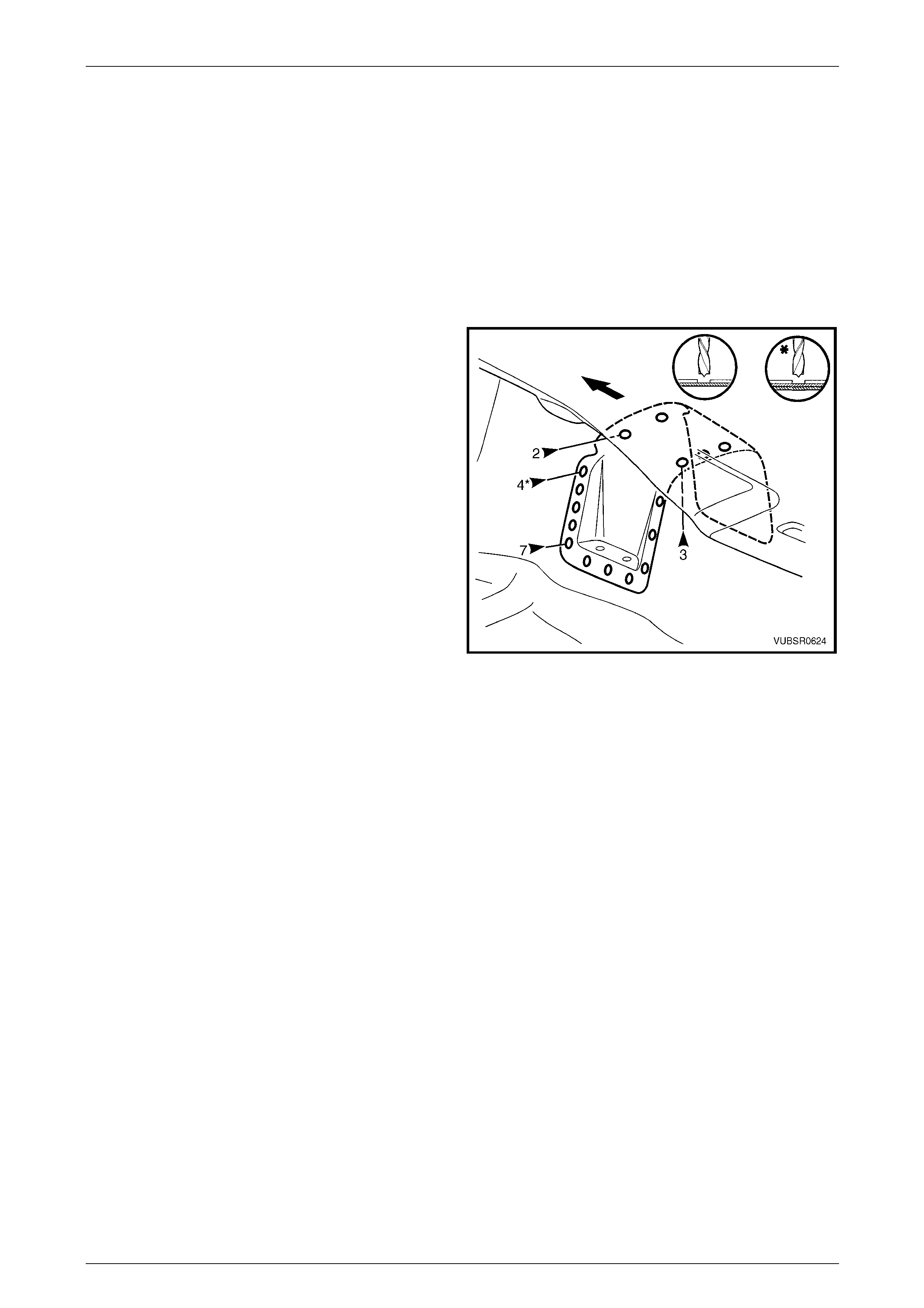
4 Spot cut the two welds front and three welds rear
attaching the propeller shaft hanger assembly to the
floor.
5 Spot cut the seven welds each side attaching the
hanger assembly to the floor.
6 Spot cut the four welds each side attaching the hang er
assembly to the floor and seat inner bracket assembly.
7 Remove the hanger assembly from the vehicle and
repair any damage to the adjacent area as required.
Figure 6A – 39
6A Cabin Floor – Sedan, Wagon, Coupe and AWD Wagon Page 6A-24
Page 6A-24
Replace
NOTE
• Spot welding is the preferred method for
attaching of panels and should be used
whenever possible. Where the spot welding
equipment available will not access the
required weld position, a plug weld should be
performed.
• The same number and position of spot welds
(or plug welds) should be used when
replacing the panel, as was used during
manufacture, in order to maintain the original
structural strength of the vehicle.
1 As required, mark the new panel with drilling locations in preparation for plug welding. Drill holes as required.
2 Prepare all mating surfaces and treat with Weld Through Primer (Item 1) as requir ed,
refer to Section 3 Body Construction.
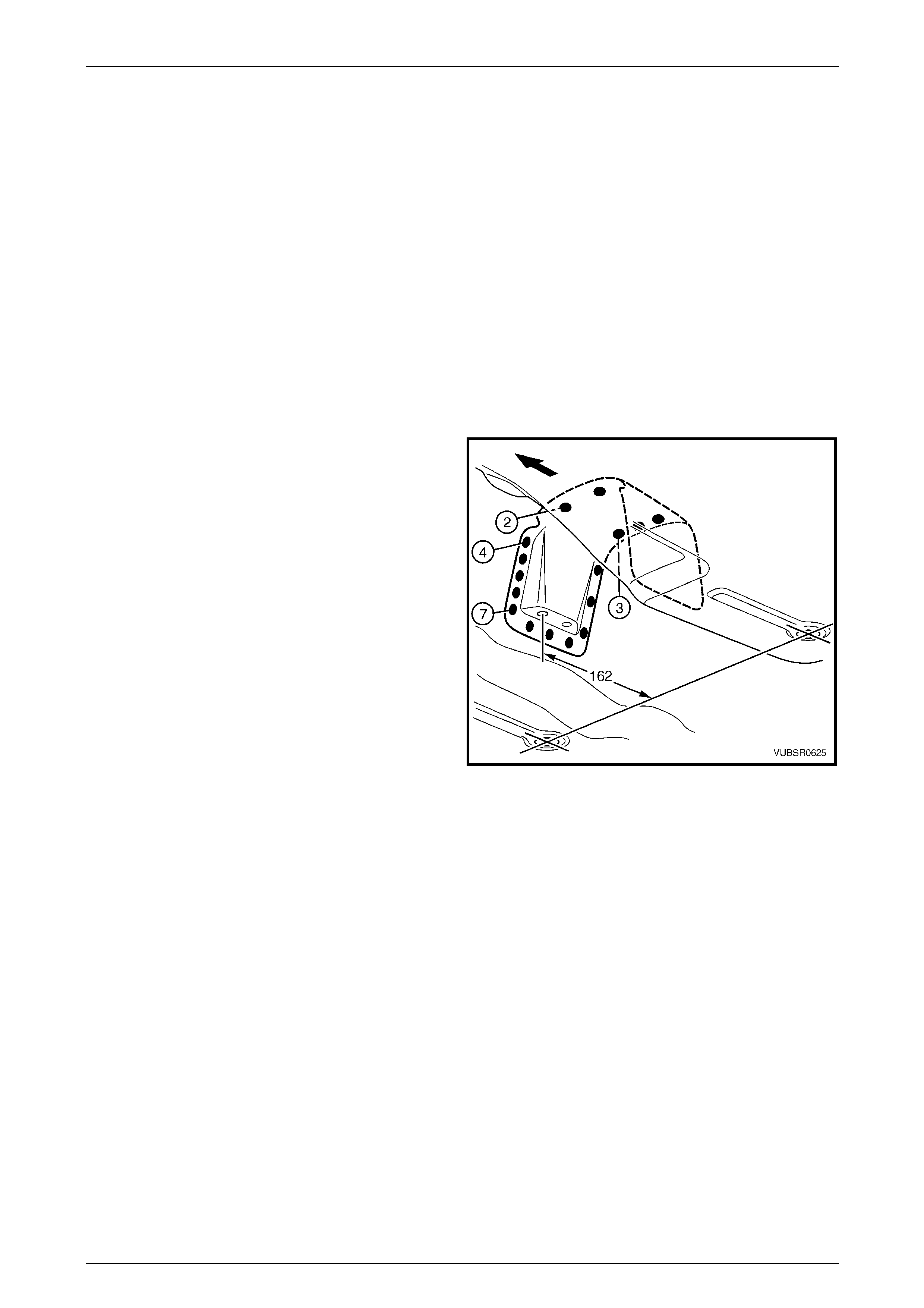
3 Install the propeller shaft hanger assem bly, positioning
each front datum hole 162 mm forward of the datum
hole centres in the floor.
4 Spot or plug weld the hanger assembly to the floor,
two places front and three places rear.
5 Spot or plug weld the hanger assembly to the floor,
seven places each side.
6 Spot or plug weld the hanger assembly to the floor and
seat inner bracket assembly, four places each side.
7 Refinish and paint panels and other components as
required. Refer to Section 3 Body Construction .
8 Apply Spray-on dea dener (Item 7) as required to the
underside of the floor,
refer to Section 3 Body Construction.
9 Apply floor deadeners as required,
refer to Section 3 Body Construction.
Figure 6A – 40
10 Install the propeller shaft and centre be aring assembly,
refer to Section 4C1 Rear Propeller Shaft and Universal Joints in the MY2005 VZ Servic e Information.
11 Reinstall the remaining bolt-on panels and components as required, refer to the appropriate Section of the MY2005
VZ Service Information.
6A Cabin Floor – Sedan, Wagon, Coupe and AWD Wagon Page 6A-25
Page 6A-25
2.9 Left-hand Transmission Support Bracket
– Replace
Remove
1 Remove the adjacent bolt-on panels and components as described in the appropriate section of the MY2005 VZ
Service Information.
2 Using a scraper and heat gun, remove the body sealer and deadener from the front floor attaching areas.
3 Spot cut the welds attaching the transmission support
bracket to the vehicle.
4 Remove the transmission support bracket from the
vehicle and repair any damag e to the adjacent area as
required.
Figure 6 – 41
6A Cabin Floor – Sedan, Wagon, Coupe and AWD Wagon Page 6A-26
Page 6A-26
Replace
NOTE
• Spot welding is the preferred method for
attaching of panels and should be used
whenever possible. Where the spot welding
equipment available will not access the
required weld position, a plug weld should be
performed.
• The same number and position of spot welds
(or plug welds) should be used when
replacing the panel, as was used during
manufacture, in order to maintain the original
structural strength of the vehicle.
1 As required, mark the new panel with drilling locations in preparation for plug welding. Drill holes as required.
2 Prepare all mating surfaces and treat with Weld Through Primer (Item 1) as requir ed,
refer to Section 3 Body Construction.
3 Position the transmission support bracket to the
dimensions shown, measuring from the front edge of
the crossmember flange.
NOTE
Positioning of the transmission support bracket is
critical to driveline orientati on.
4 Temporarily bolt the transmission crossmember in
position to help locate the mount.
5 Spot or plug weld the transmission supp ort bracket to
the front floor panel assembly.
6 Refinish and paint panels and other components as
required. Refer to Section 3 Body Construction .
7 Apply Cavity Wax (Item 8) as required to the inside of
any box sections or areas inaccessible to paint,
refer to Section 3 Body Construction. Figure 6 – 42
8 Apply floor deadeners as req uired, refer to Section 3 Body Construction.
9 Apply Spray-on Deadener (Item 7) as required to the under side of the floor, refer to Section 3 Body Construction.
10 Reinstall the remaining bolt-on panels and components as required, refer to the appropriate Section of the MY2005
VZ Service Information.