
6C Cabin Floor and Seatback Assembly – Utility Page 6C-1
Page 6C-1
Section 6C
Cabin Floor and Seatback Assembly – Utility
ATTENTION
Before performing any service operation or other procedure described in this Section, refer to Section 2
Precautions in this Supplement and Section 00 Warnings, Cautions and Notes in the MY2005 VZ Service
Information for correct workshop practices with regard to safety and/or property damage.
The structure of the body shell has been
developed using complex design and
development techniques. In addition to
meeting all required standards, the vehicle
body is also a critical part of the overall safety
systems. It is therefore imperative the repair
procedures described here are adhered to
during all vehicle body repairs.
1 General Description ...............................................................................................................................2
1.1 Cabin Floor and Seatback Assembly Components ............................................................................................ 2
2 Service Operations.................................................................................................................................4
2.1 Front Floor Panel Assembly – Replace................................................................................................................ 4
Remove................................................................................................................................................................... 4
Replace................................................................................................................................................................... 6
2.2 Inner Rocker Panel Assembly – Replace............................................................................................................. 8
Remove................................................................................................................................................................... 8
Replace................................................................................................................................................................... 9
2.3 Load Compartment Extension Outer Panel and Bracket – Replace................................................................ 11
Remove................................................................................................................................................................. 11
Replace................................................................................................................................................................. 12
2.4 Front Seatback Panel Outer – Replace .............................................................................................................. 14
Remove................................................................................................................................................................. 14
Replace................................................................................................................................................................. 16
2.5 Front Seatback Panel – Replace......................................................................................................................... 18
Remove................................................................................................................................................................. 18
Replace................................................................................................................................................................. 20
2.6 Front Floor Rear Extension Assembly – Replace............................................................................................. 22
Remove................................................................................................................................................................. 22
Replace................................................................................................................................................................. 24
6C Cabin Floor and Seatback Assembly – Utility Page 6C-2
Page 6C-2
1 General Description
With the following exceptions the Utility Cabin Floor and Seatback assembly informatio n carries over from Sedan
vehicles. For information not covered in this Section,
refer to Section 6A Cabin Floor – Sedan, Wagon, Coupe and AWD Wagon, Wagon, Coupe and AWD Wagon.
• Front Floor Panel Assembly
• Inner Rocker Panel Assembly
• Load Compartment Extension Outer Panel and Bracket.
• Front Seatback Panel Outer.
• Front Seatback Panel.
• Front Floor Rear Extension Assembly.
Removal of bolt-on panels and mecha nica l components is not covered. For information on the removal of these parts,
reference must be made to the appropriate Section of the MY2005 VZ Service Information.
• When repairing the cabin floor of the vehicle,
care must be taken to ensure the structure is
returned to its original production
configuration.
• It is imperative that the correct body
adhesives, sealers, deadeners and cavity
waxes are used when repairing the body
structure. Refer to Section 3C Body
Construction – Utility for details of the correct
materials and their commercially available
equivalents.
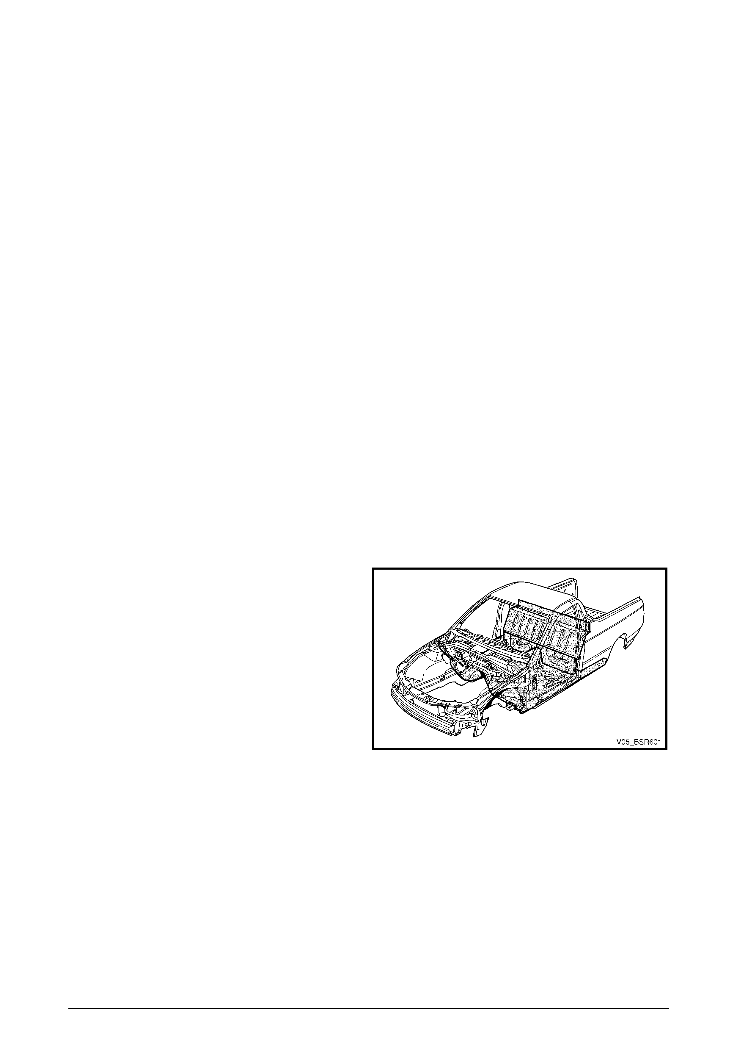
1.1 Cabin Floor and Seatback Assembly
Components
The shaded components in Figure 6C – 1 are the cabin floor
and seatback assembly components fitted to vehicles dealt
with in this Section. The Service Operations not covered in
this section, refer to Section 3A Body Construction – Sedan.
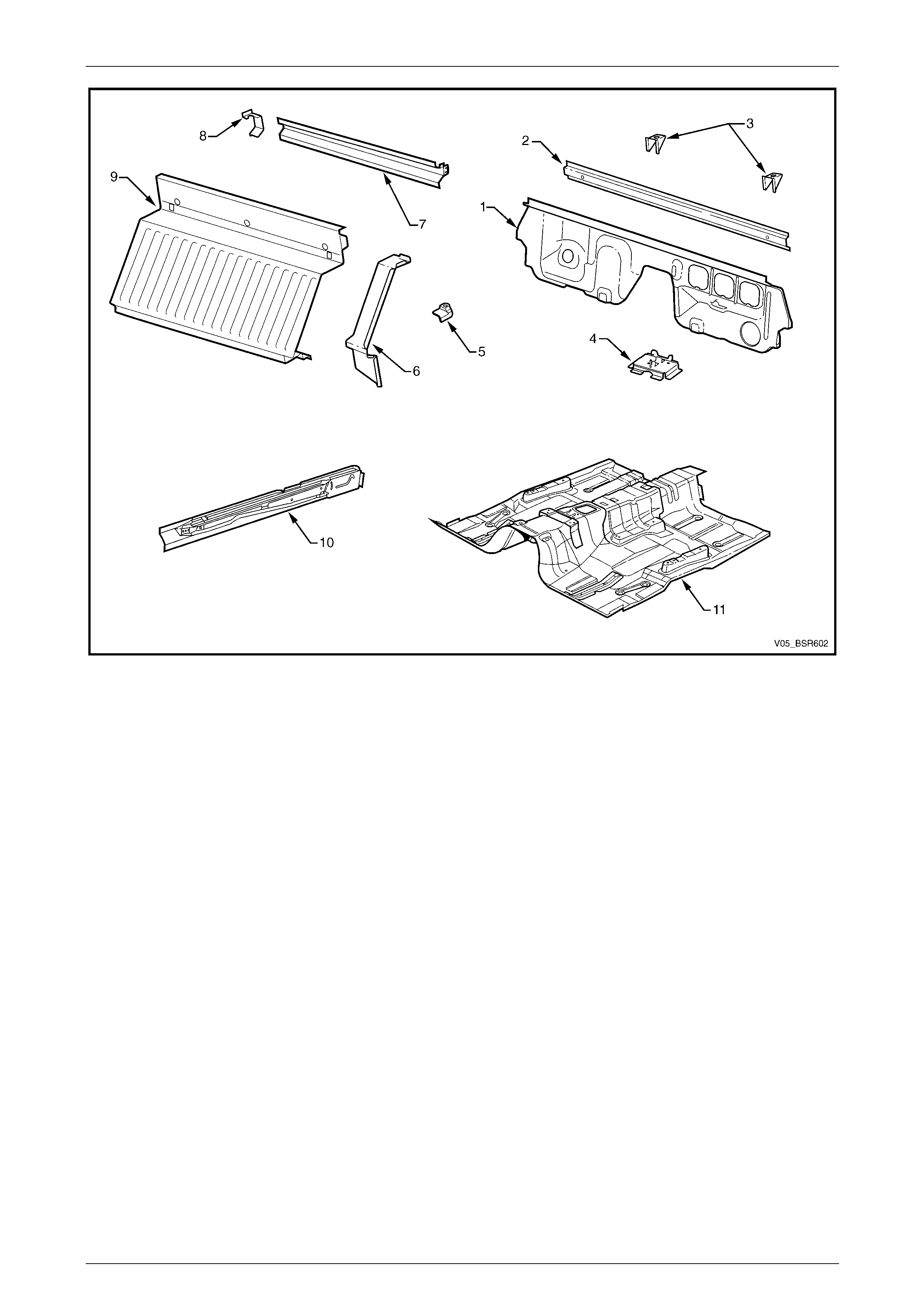
The components and assemblies shown in Figure 6C – 2
and are the serviceable parts that form the
basis of the repair procedures in this Sectio n.
For a detailed view of the body components,
refer to Section 3C Body Construction – Utility.
NOTE
Always refer to an Authorised Retailer for spare
parts availability configurations.
Figure 6C – 1
6C Cabin Floor and Seatback Assembly – Utility Page 6C-3
Page 6C-3
Figure 6C – 2
Legend
1 Front Floor Rear Extension Assembly
2 Front Floor Rear Extension Reinforcement
3 Fuel Tank Bracket Assembly
4 Jack Stowage Bracket
5 Front Tie Down Bracket, Left-hand / Right-hand
6 Front Seatback Panel Outer, Left-hand / Right-hand
7 Load Compartment Extension Outer Panel
8 Load Compartment Extension Panel Bracket, Right-hand
9 Front Seatback Panel
10 Inner Rocker Panel Assembly, Left-hand / Right-hand
11 Front Floor Panel Assembly
6C Cabin Floor and Seatback Assembly – Utility Page 6C-4
Page 6C-4
2 Service Operations
2.1 Front Floor Panel Assembly – Replace
Care must be taken to avoid cutting the fuel,
brake or emission control pipes.
Remove
1 Remove the adjacent bolt-on panels a nd components
as described in the appropriate Section of the MY2005
VZ Service Information.
2 Remove the adjoining panels as required, refer to the
relevant Section in this Supplement.
3 Secure the vehicle on a suitable fixture. As a
minimum, support the structural sections of the vehicle
on safety stands.
4 Using a scraper and heat gun, remove the body sealer
and deadener from the front floor attaching areas.
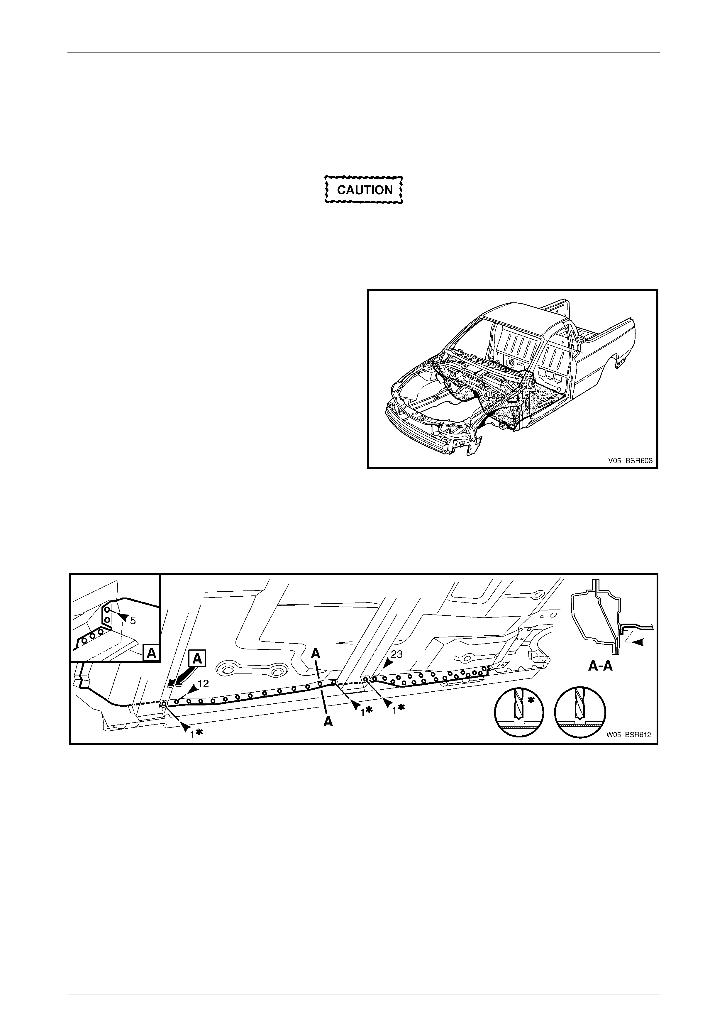
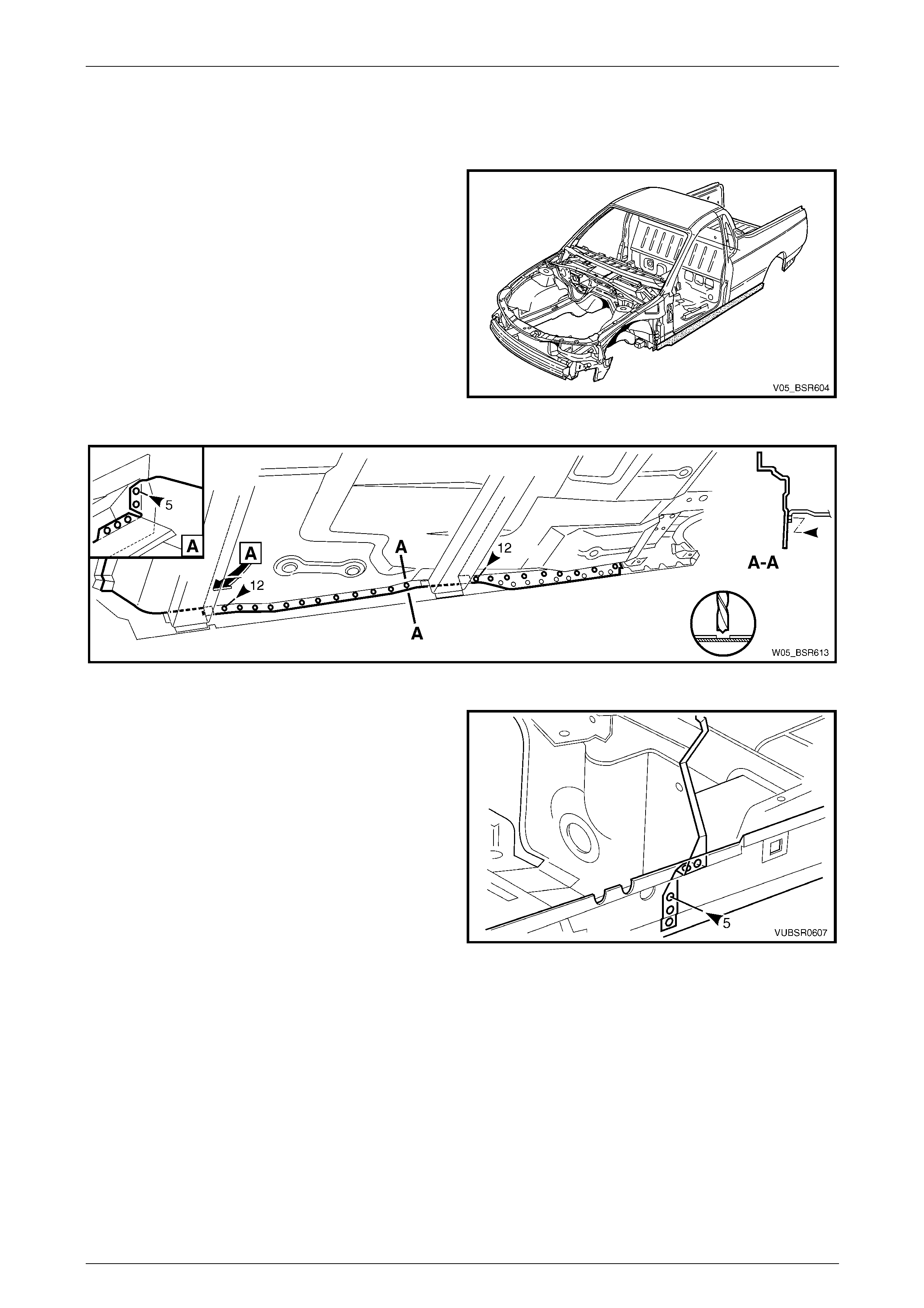
5 Spot cut the welds attaching the front floor rear
extension to the front floor panel assembly, refer to
2.6 Front Floor Rear Extension Assembly – Replace. Figure 6C – 3
6 Spot cut the welds attaching the front floor panel extension to the front floo r panel assembly,
refer to Section 6A Cabin Floor – Sedan, Wagon, Coupe and AWD Wagon, Wagon, Coupe and AWD Wagon.
7 From underneath the vehicle, spot cut the welds attaching the front floor panel assembly to the inner rocker panel
assembly, refer to Figure 6C – 4.
Figure 6C – 4
6C Cabin Floor and Seatback Assembly – Utility Page 6C-5
Page 6C-5
8 From underneath the vehicle, spot cut the welds
attaching the park brake cable bracket to the rear floor
panel assembly.
9 On each side of the vehicle, spot cut the welds
attaching the front floor panel assembly to the front
side rail assemblies, refer to Figure 6C – 6.
Figure 6C – 5
Figure 6C – 6
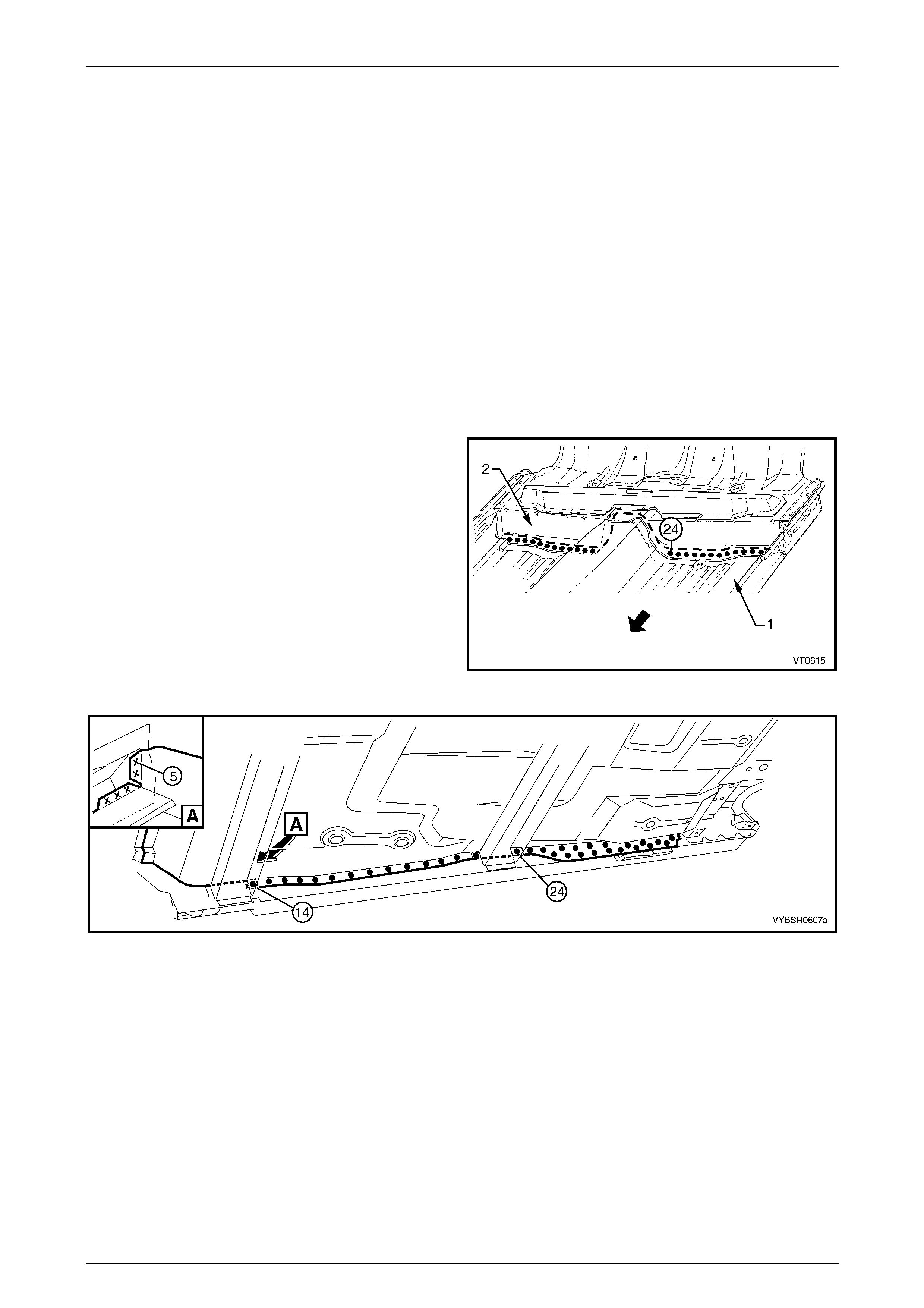
10 Spot cut the welds attaching the front floor panel
assembly (1) to the rear floor panel assembly (2).
11 Remove the front floor assembly from the vehicle and
repair any damage to adjacent panels as required.
12 Check and rectify the alignme nt of
the body as required,
refer to Section 3C Body Construction – Utility.
Figure 6C – 7
6C Cabin Floor and Seatback Assembly – Utility Page 6C-6
Page 6C-6
Replace
NOTE
• Spot welding is the preferred method for
attaching of panels and should be used
whenever possible. Where the spot welding
equipment available will not access the
required weld position, a plug weld should be
performed.
• The same number and position of spot welds
(or plug welds) should be used when
replacing the panel, as was used during
manufacture, in order to maintain the original
structural strength of the vehicle.
1 As required, mark the new panel with drilling locations in preparation for plug welding. Drill holes as required.
2 Prepare all mating surfaces and treat with Weld Through Primer (Item 1) as requir ed,
refer to Section 3C Body Construction – Utility.
3 Secure the front floor panel assembly (1) in position
and make several tack welds around its
circumference. Plug weld to the rear floor panel
assembly (2).
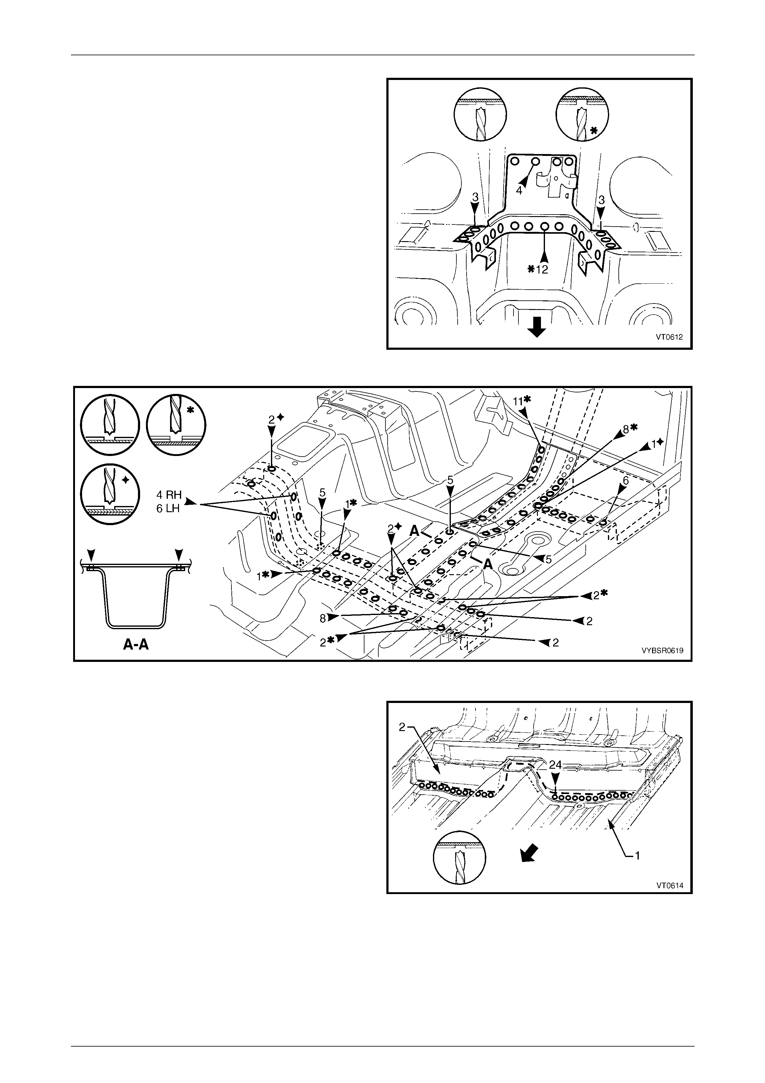
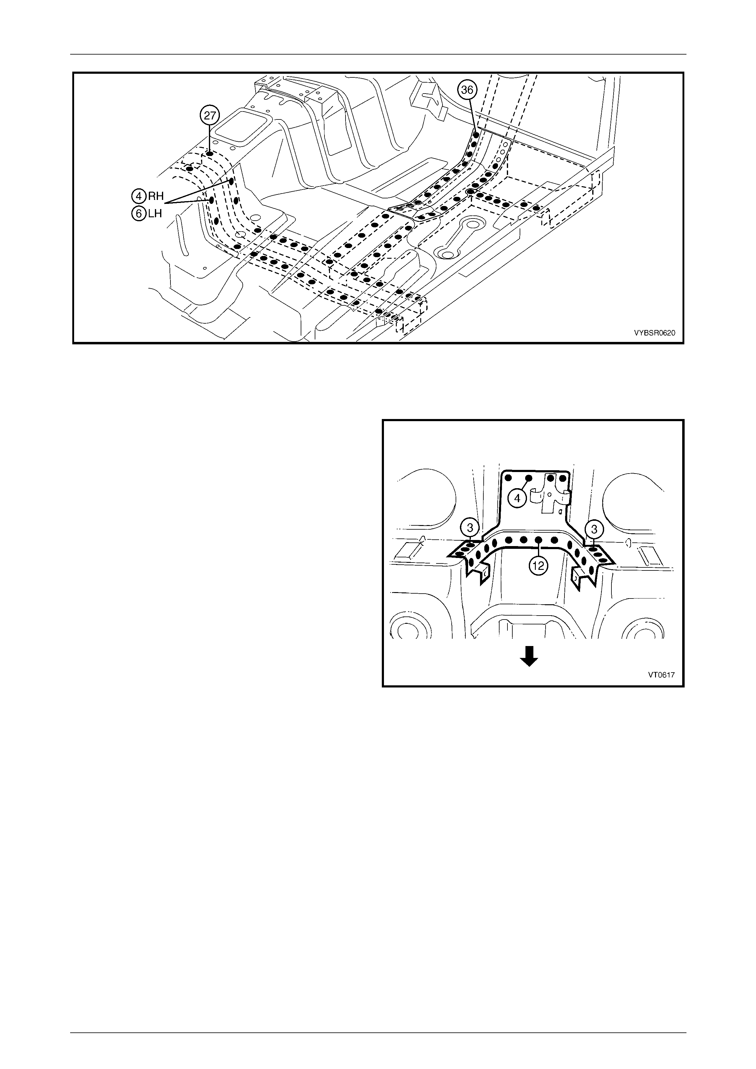
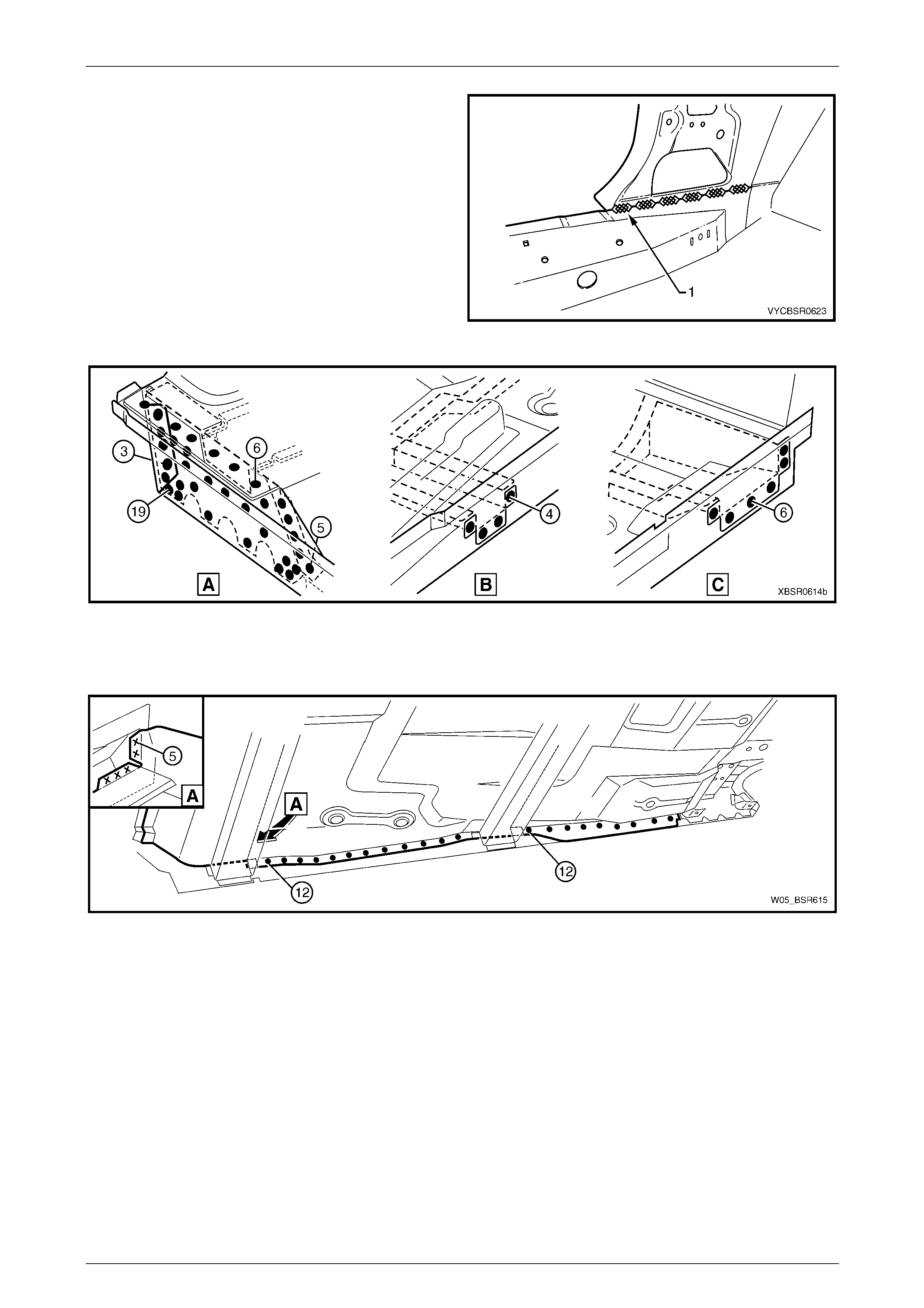
4 From underneath the vehicle, spot or plug weld the
front floor assembly to the inner rocker panel
assembly, 14 places forward of the crossmember and
24 places rear of the crossmember. From inside the
vehicle, also spot weld, five places. Figure 6C – 9.
Figure 6C – 8
Figure 6C – 9
5 Replace the front floor panel extension, or weld the extension to the front floor panel assembly,
refer to Section 6A Cabin Floor – Sedan, Wagon, Coupe and AWD Wagon .
6 On each side of the vehicle, plug weld the front floor panel assembly to the front side rail assemblies,
refer to Figure 6C – 10.
6C Cabin Floor and Seatback Assembly – Utility Page 6C-7
Page 6C-7
Figure 6C – 10
7 Plug weld the front floor rear extension to the front floor panel assembly,
refer to 2.6 Front Floor Rear Extension Assembly – Repl ace.
8 Reinstall the park brake cable bracket to the rear floor
panel assembly.
9 Replace any other remov ed panels as required, refer
to the relevant Section in this Supplement.
10 Refinish and paint panels and other components as
required. Refer to Section 3 Body Construction .
11 Apply Joint Sealer (Item 3) as required.
Refer to Section 3C Body Construction – Utility.
12 Apply Cavity Wax (Item 8) as required to the inside of
any box sections or areas inaccessible to paint,
refer to Section 3C Body Construction – Utility.
13 Apply floor deadeners as required,
refer to Section 3C Body Construction – Utility.
14 Apply Spray-on dea dener (Item 7) as required to the
underside of the floor,
refer to Section 3C Body Construction – Utility.
15 Reinstall the remaining bolt-on panels and
components as required, refer to the appropriate
Section of the MY2005 VZ Service Information.
Figure 6C – 11
6C Cabin Floor and Seatback Assembly – Utility Page 6C-8
Page 6C-8
2.2 Inner Rocker Panel Assembly – Replace
Remove
1 Remove the adjacent bolt-on panels a nd components
as described in the appropriate Section of the MY2005
VZ Service Information.
2 Secure the vehicle on a suitable fixture. As a
minimum, support the structural sections of the vehicle
on safety stands.
3 Remove the adjacent panels as required, refer to the
relevant Section in this Supplement.
4 Spot cut the welds attaching the front floor panel
assembly to the inner rocker panel as required.
Refer to Figure 6C – 13.
Figure 6C – 12
Figure 6C – 13
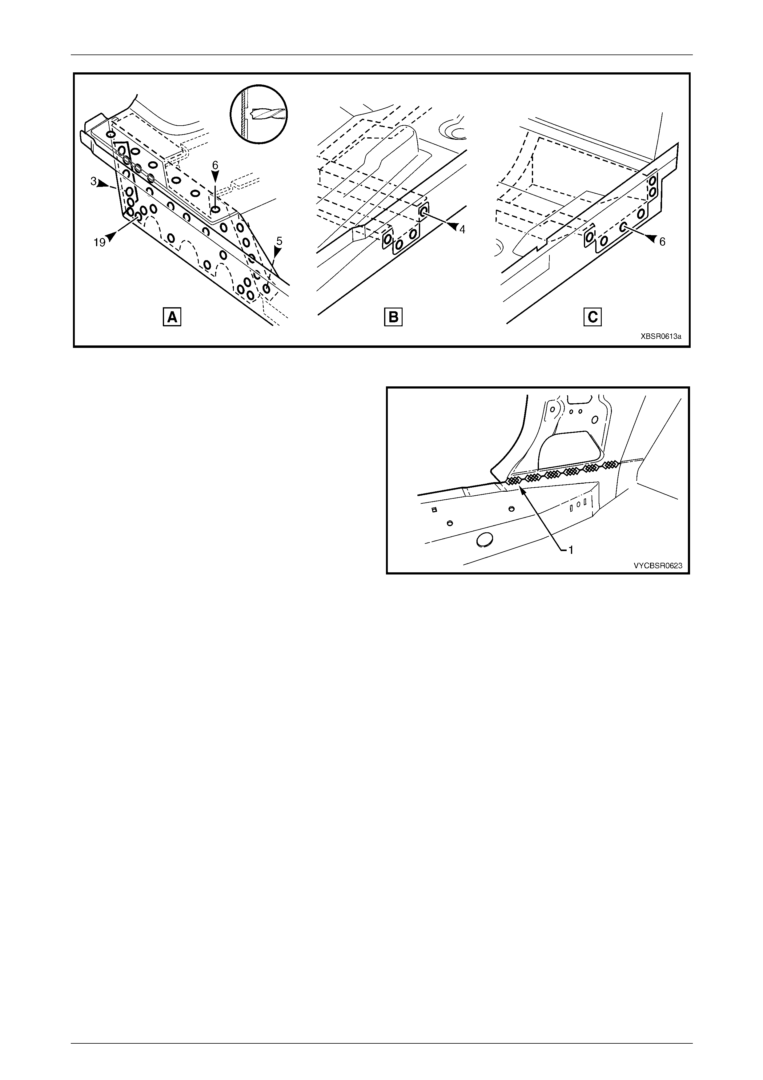
5 Spot cut the welds attaching the inner rocker panel
assembly to the front floor rear extension assembly.
6 Spot cut the welds attaching the inner rocker panel
assembly to the rear floor panel outer extension (A),
centre crossmember (B), and front floor panel support
(C), refer to Figure 6C – 15.
Figure 6C – 14
6C Cabin Floor and Seatback Assembly – Utility Page 6C-9
Page 6C-9
Figure 6C – 15
7 Remove the MIG welds (1) attaching the inner rocker
panel to the hinge pillar inner assembly.
8 Remove the inner rocker panel from the vehicle and
repair any damage to adjacent panels as required.
9 Check and rectify the alignme nt
of the body as required,
refer to Section 3C Body Construction – Utility.
Figure 6C – 16
Replace
NOTE
• Spot welding is the preferred method for
attaching of panels and should be used
whenever possible. Where the spot welding
equipment available will not access the
required weld position, a plug weld should be
performed.
• The same number and position of spot welds
(or plug welds) should be used when
replacing the panel, as was used during
manufacture, in order to maintain the original
structural strength of the vehicle.
1 As required, mark the new panel with drilling locations in preparation for plug welding. Drill holes as required.
2 Prepare all mating surfaces and treat with Weld Through Primer (Item 1) as requir ed,
refer to Section 3C Body Construction – Utility.
3 Clamp the inner rocker panel in positi on, noting to ensure it fits behind the hinge pillar inn er assemb ly.
6C Cabin Floor and Seatback Assembly – Utility Page 6C-10
Page 6C-10
4 Make six MIG welds (1) to attach inner rocker panel
assembly to the hinge pillar inner assembly.
5 Plug weld the inner rocker pa nel to the rear floor panel
outer extension (A), centre crossmember (B) and front
floor panel support (C), refer Figure 6C – 18.
Figure 6C – 17
Figure 6C – 18
6 Spot or plug weld the front floor panel assembly to the inner rocker panel, undern eath and inside.
Refer to Figure 6C – 19.
Figure 6C – 19
7 Replace the adjoining removed panels as required, refer to the relevant Section in this Supplement.
8 Refinish and paint panels and other components as required. Refer to Section 3 Body Construction.
9 Apply Joint Sealer (Item 3) as required. Refer to Section 3C Body Construction – Utility.
10 Apply Cavity Wax (Item 8) as required to the inside of any box secti ons or areas inaccessible to paint,
refer to Section 3C Body Construction – Utility.
11 Reinstall the remaining bolt-on panels and components as required, refer to the appropriate Section of the MY2005
VZ Service Information.
6C Cabin Floor and Seatback Assembly – Utility Page 6C-11
Page 6C-11
2.3 Load Compartment Extension Outer
Panel and Bracket – Replace
Remove
1 Remove the adjacent bolt-on panels a nd components
as described in the appropriate Section of the MY2005
VZ Service Information.
2 Remove the rear window, refer Section 1A6 Stationary
Windows in the MY2005 VZ Service Information.
3 Remove the adjacent panels as required, refer to the
relevant Section in this Supplement.
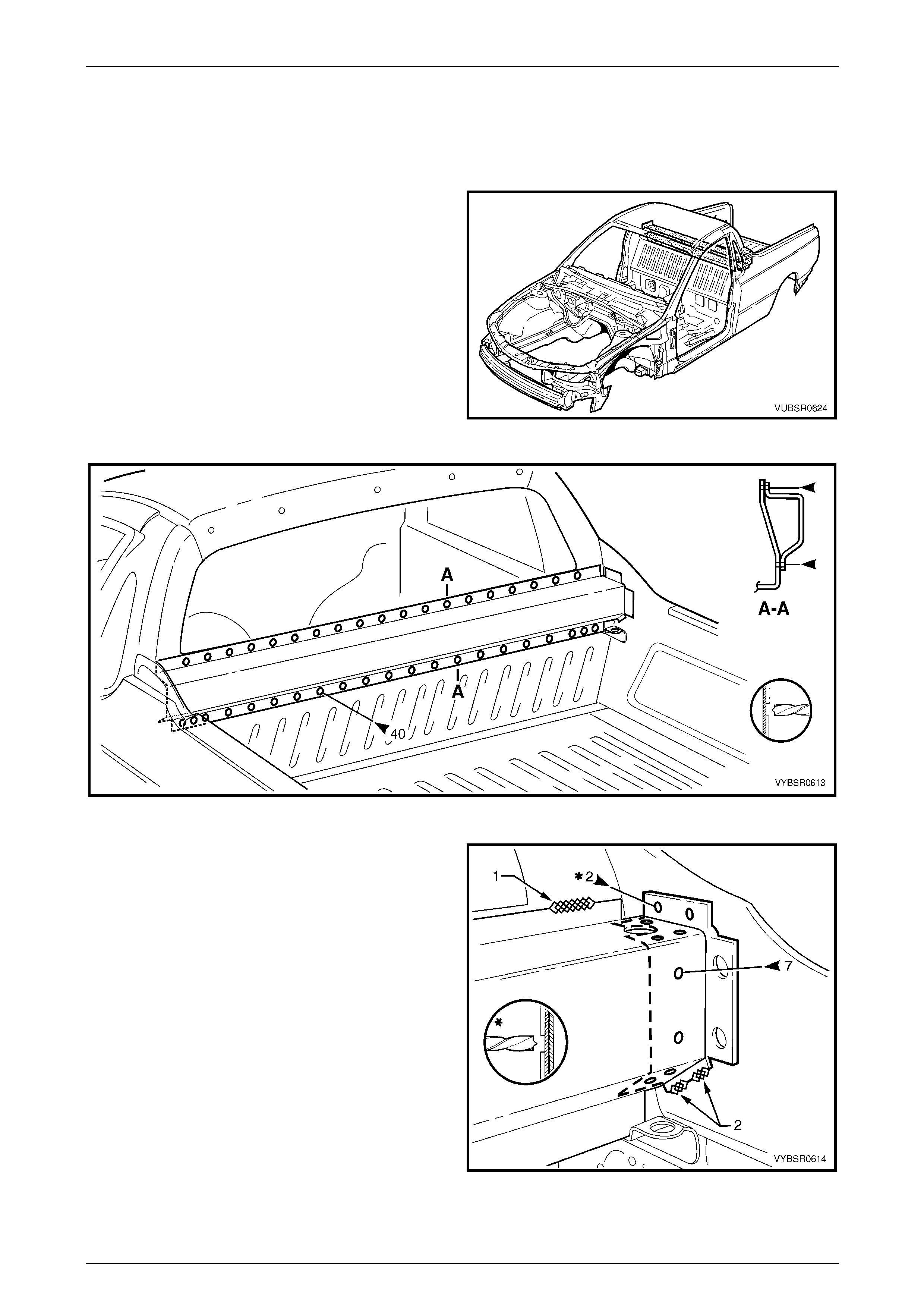
4 Spot cut the 40 welds attaching the load compartment
extension outer pane l to the front seatback panel,
refer to Figure 6C – 21.
Figure 6C – 20
Figure 6C – 21
5 For the right-hand side either:
a spot cut the two welds and grind off the three
MIG welds (1) and (2) attaching the load
compartment extension outer panel and load
compartment extension panel bracket, or
b spot cut the seven welds attaching the load
compartment extension outer panel to the load
compartment extension panel bracket and grind
off the MIG weld (1).
6 For the left-hand side, spot cut the t wo welds and
grind off the three MIG welds attaching the load
compartment extension outer panel.
7 Remove the panel from the vehicle and re pair any
damage to adjacent panels.
8 Check and rectify the alignme nt of the
body as required,
refer to Section 3C Body Construction – Utility. Figure 6C – 22
6C Cabin Floor and Seatback Assembly – Utility Page 6C-12
Page 6C-12
Replace
NOTE
• Spot welding is the preferred method for
attaching of panels and should be used
whenever possible. Where the spot welding
equipment available will not access the
required weld position, a plug weld should be
performed.
• The same number and position of spot welds
(or plug welds) should be used when
replacing the panel, as was used during
manufacture, in order to maintain the original
structural strength of the vehicle.
1 As required, mark the new panel with drilling locations in preparation for plug welding. Drill holes as required.
2 Prepare all mating surfaces and treat with Weld Through Primer (Item 1) as requir ed,
refer to Section 3 Body Construction.
3 Clamp the panel and bracket (if removed) i n positi on.
NOTE
Ensure the two holes through the load
compartment extension outer panel and side
panel inner upper are aligned.
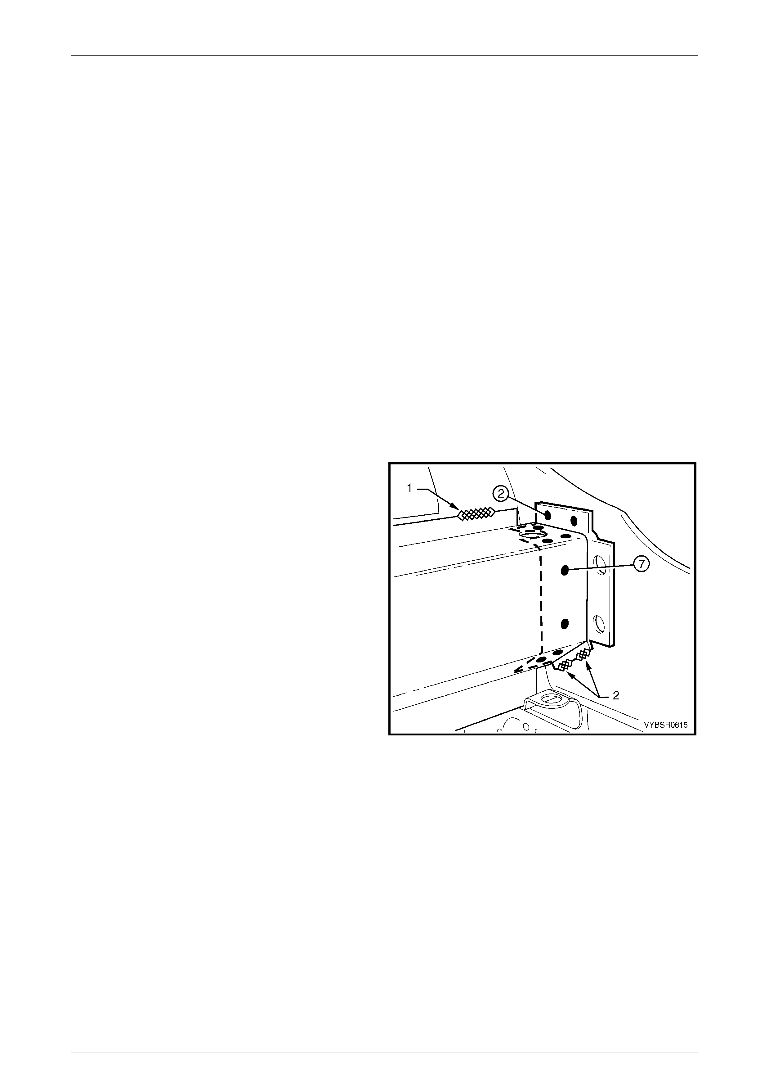
4 For the right-hand side:
a spot or plug weld seven places, the load
compartment extension outer panel to the load
compartment panel bracket.
b MIG weld one place (1) 25 mm, the load
compartment extension outer panel to the side
inner upper front panel.
If the load compartment panel bracket was removed
also:
a Spot or plug weld two places, the load
compartment panel bracket to the side panel
inner upper and rear quarter panel.
b MIG weld 20 mm two places (2), the load
compartment panel bracket to the side inner
upper panel.
5 For the left-hand side:
• Spot or plug weld two places, the load
compartment extension outer panel to the side
panel inner upper and rear quarter panel.
• MIG weld 20 mm two places (2), the load
compartment extension outer panel to the side
inner upper panel and one place (1) 25 mm, the
side inner upper front panel.
Figure 6C – 23
6C Cabin Floor and Seatback Assembly – Utility Page 6C-13
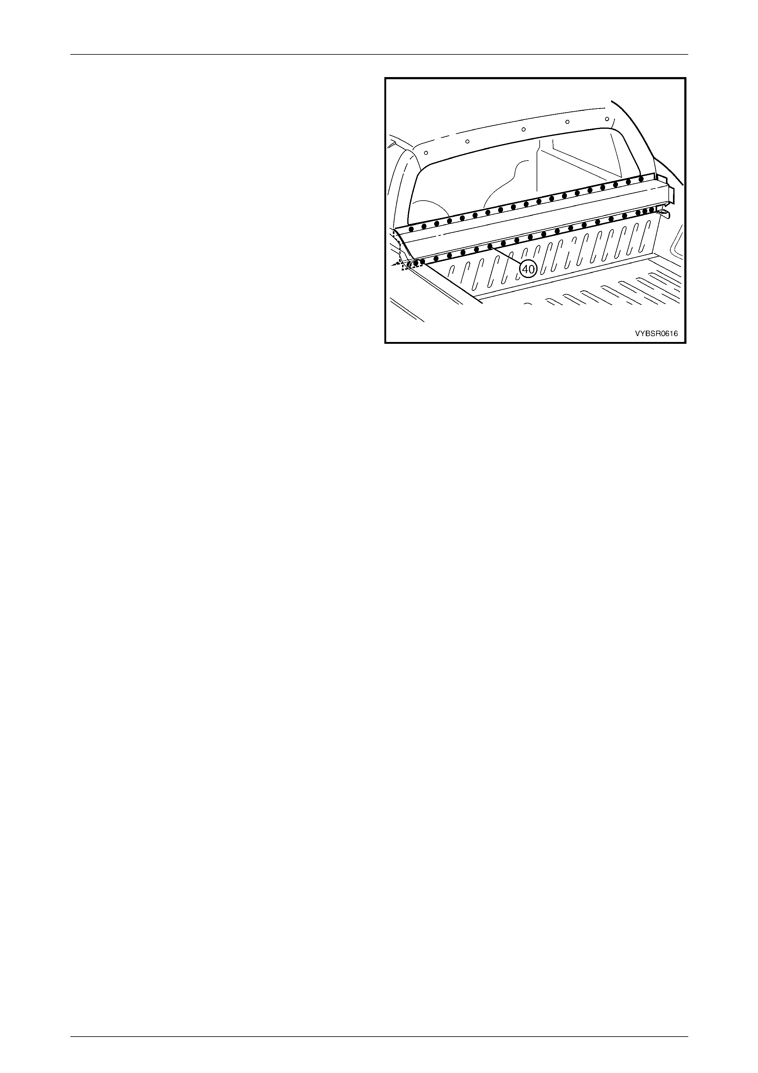
Page 6C-13
6 Spot or plug weld 40 places, the load com pa rtment
extension outer pane l to the front seatback panel.
7 Replace the adjoining removed panels as required,
refer to the relevant Section in this Supplement.
8 Refinish and paint panels and other components as
required. Refer to Section 3 Body Construction .
9 Apply Joint Sealer (Item 3) as required.
Refer to Section 3C Body Construction – Utility.
10 Apply Cavity Wax (Item 8) as required to the inside of
any box sections or areas inaccessible to paint,
refer to Section 3C Body Construction – Utility.
11 Install the rear window, refer to Section 1A6 Stationary
Windows in the MY2005 VZ Service Information.
12 Install the remaining components as described in the
MY2005 VZ Service Information.
Figure 6C – 24
6C Cabin Floor and Seatback Assembly – Utility Page 6C-14
Page 6C-14
2.4 Front Seatback Panel Outer – Replace
Remove
1 Remove the adjacent bolt-on panels a nd components
as described in the appropriate Section of the MY2005
VZ Service Information.
2 Remove the rear window, refer Section 1A6 Stationary
Windows in the MY2005 VZ Service Information.
3 Secure the vehicle on a suitable fixture. As a
minimum, support the structural sections of the vehicle
on safety stands.
4 Remove the adjacent panels as required, refer to the
relevant Section in this Supplement.
5 Grind off the two MIG welds (1) and spot cut the welds
attaching the front tie down bracket to each side of the
vehicle, refer to Figure 6C – 26. Figure 6C – 25
Figure 6C – 26
6C Cabin Floor and Seatback Assembly – Utility Page 6C-15
Page 6C-15
6 Spot cut the welds attaching the front seatback panel
outer to the:
• front floor rear extension assembly, seven
places,
• side inner upper panel, six places,
• load floor panel outer extension, three places.
7 Grind off the MIG weld (1) attaching the front floor rear
extension asse mbly to the front seatback panel outer.
Figure 6C – 27
8 Spot cut the welds attaching the front seatback panel
outer to the:
• front seatback panel, eight places,
• side inner upper front panel and side inner upper
front panel, one place,
• side inner upper front panel, two places,
• side inner upper front panel and side inner upper
panel, one place,
• side inner upper panel, six places,
• front seatback panel and front floor rear
extension asse mbly, three places.
9 Grind off the MIG welds (1) and (2) attaching the front
seatback panel outer to the front seatback panel and
side inner upper front panel.
10 Remove the panel(s) from the vehicle and repair any
damage to adjacent panels a s required.
11 Check and rectify the alignme nt of
the body as requir ed,
refer to Section 3C Body Construction – Utility.
Figure 6C – 28
6C Cabin Floor and Seatback Assembly – Utility Page 6C-16
Page 6C-16
Replace
NOTE
• Spot welding is the preferred method for
attaching of panels and should be used
whenever possible. Where the spot welding
equipment available will not access the
required weld position, a plug weld should be
performed.
• The same number and position of spot welds
(or plug welds) should be used when
replacing the panel, as was used during
manufacture, in order to maintain the original
structural strength of the vehicle.
1 As required, mark the new panel with drilling locations in preparation for plug welding. Drill holes as required.
2 Prepare all mating surfaces and treat with Weld Through Primer (Item 1) as requir ed,
refer to Section 3C Body Construction – Utility.
3 Clamp the front seatback panel outer in pos ition.
4 Spot or plug weld the front seatback panel outer to
the:
• front seatback panel, eight places,
• side inner upper front panel and side inner upper
front panel, one place,
• side inner upper front panel, two places,
• side inner upper front panel and side inner upper
panel, one place,
• side inner upper panel, six places,
• front seatback panel and front floor rear
extension asse mbly, three places.
5 MIG weld the front seatback panel outer (1) 50 mm to
the front seatback panel and (2) 25 mm to the side
inner upper front panel.
Figure 6C – 29
6 Spot or plug weld the front seatback panel outer to
the:
• front floor rear extension assembly, seven
places,
• side inner upper panel, six places,
• load floor panel outer extension, three places.
7 MIG weld (1) 25 mm the front floor rear extension
assembly to the front seatback panel outer.
8 MIG weld (1) two places and spot or plug weld the
front tie down bracket, each side of the vehicle,
refer to Figure 6C – 31. Figure 6C – 30
6C Cabin Floor and Seatback Assembly – Utility Page 6C-17
Page 6C-17
Figure 6C – 31
9 Replace the adjoining removed panels as required, refer to the relevant Section in this Supplement.
10 Refinish and paint panels and other components as required. Refer to Section 3 Body Construction.
11 Apply Joint Sealer (Item 3) as required. Refer to Section 3C Body Construction – Utility.
12 Apply Cavity Wax (Item 8) as required to the inside of any box secti ons or areas inaccessible to paint,
refer to Section 3C Body Construction – Utility.
13 Install the rear window, refer to Section 1A6 Stationary Windows in the MY200 5 VZ Service Information.
14 Install the remaining compon ents as descr ibed in the MY2005 VZ Service Information.

6C Cabin Floor and Seatback Assembly – Utility Page 6C-18
Page 6C-18
2.5 Front Seatback Panel – Replace
Remove
1 Remove the adjacent bolt-on panels a nd components
as described in the appropriate Section of the MY2005
VZ Service Information.
2 Remove the rear window, refer Section 1A6 Stationary
Windows in the MY2005 VZ Service Information.
3 Secure the vehicle on a suitable fixture. As a
minimum, support the structural sections of the vehicle
on safety stands.
4 Remove the adjacent panels as required, refer to the
relevant Section in this Supplement.
5 Spot cut the welds attaching the front seatback panel
to the front floor rear extension assembly and front
seatback panel outer, refer to Figure 6C – 33.
6 Grind off the MIG welds (1) attaching the front
seatback panel to the front seatback panel outer and
side inner upper front panel, refer to Figure 6C – 33.
Figure 6C – 32
Figure 6C – 33
6C Cabin Floor and Seatback Assembly – Utility Page 6C-19
Page 6C-19
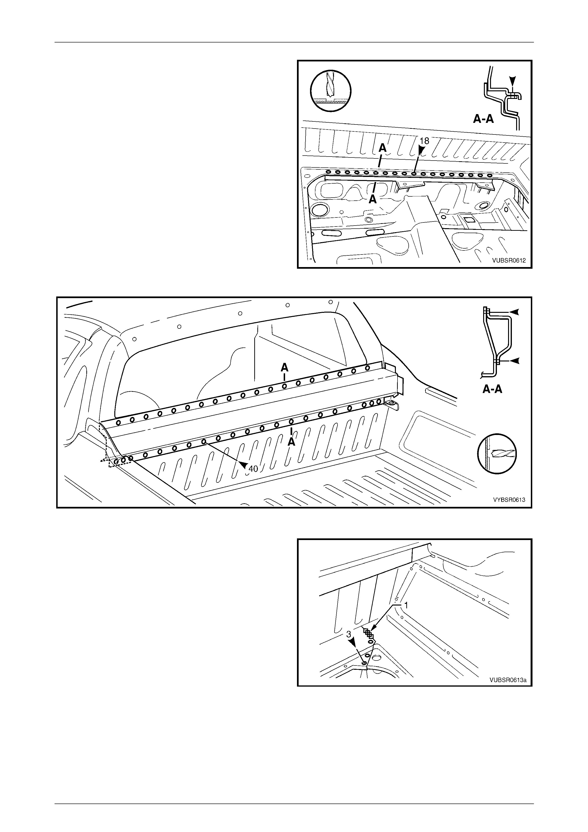
7 Spot cut the 18 welds attaching the front seatback
panel to the front floor rear extension reinforc ement.
8 Spot cut the 40 welds attaching the front seatback
panel to the load compartment extensio n outer panel,
refer to Figure 6C – 35.
NOTE
If the load compartment extension outer panel is
also being removed, this procedure is not
required.
Figure 6C – 34
Figure 6C – 35
9 Spot cut the three welds and grind off the MIG weld (1)
attaching the front seatback panel to the load floor
panel outer extension.
10 If the load compartment extension outer panel is also
being removed, refer to 2.3 Load Compartment
Extension Outer Panel and Bracket – Repla c e .
11 Remove the panel from the vehicle and re pair any
damage to adjacent panels a s required.
12 Check and rectify the alignme nt of
the body as requir ed,
refer to Section 3C Body Construction – Utility.
Figure 6C – 36
6C Cabin Floor and Seatback Assembly – Utility Page 6C-20
Page 6C-20
Replace
NOTE
• Spot welding is the preferred method for
attaching of panels and should be used
whenever possible. Where the spot welding
equipment available will not access the
required weld position, a plug weld should be
performed.
• The same number and position of spot welds
(or plug welds) should be used when
replacing the panel, as was used during
manufacture, in order to maintain the original
structural strength of the vehicle.
1 As required, mark the new panel with drilling locations in preparation for plug welding. Drill holes as required.
2 Prepare all mating surfaces and treat with Weld Through Primer (Item 1) as requir ed,
refer to Section 3C Body Construction – Utility.
3 Clamp the front seatback panel in position.
4 Spot or plug weld the front seatback panel to the front
floor rear extension reinforcement.
5 Spot or plug weld the front seatback panel to the front
floor rear extension assembly and front seatback
panel outer, refer to Figure 6C – 38.
6 MIG weld 50 mm two places each side (1), the front
seatback panel to the and front seatback panel outer
and side inner upper front pan el,
refer to Figure 6C – 38.
Figure 6C – 37
Figure 6C – 38
6C Cabin Floor and Seatback Assembly – Utility Page 6C-21
Page 6C-21
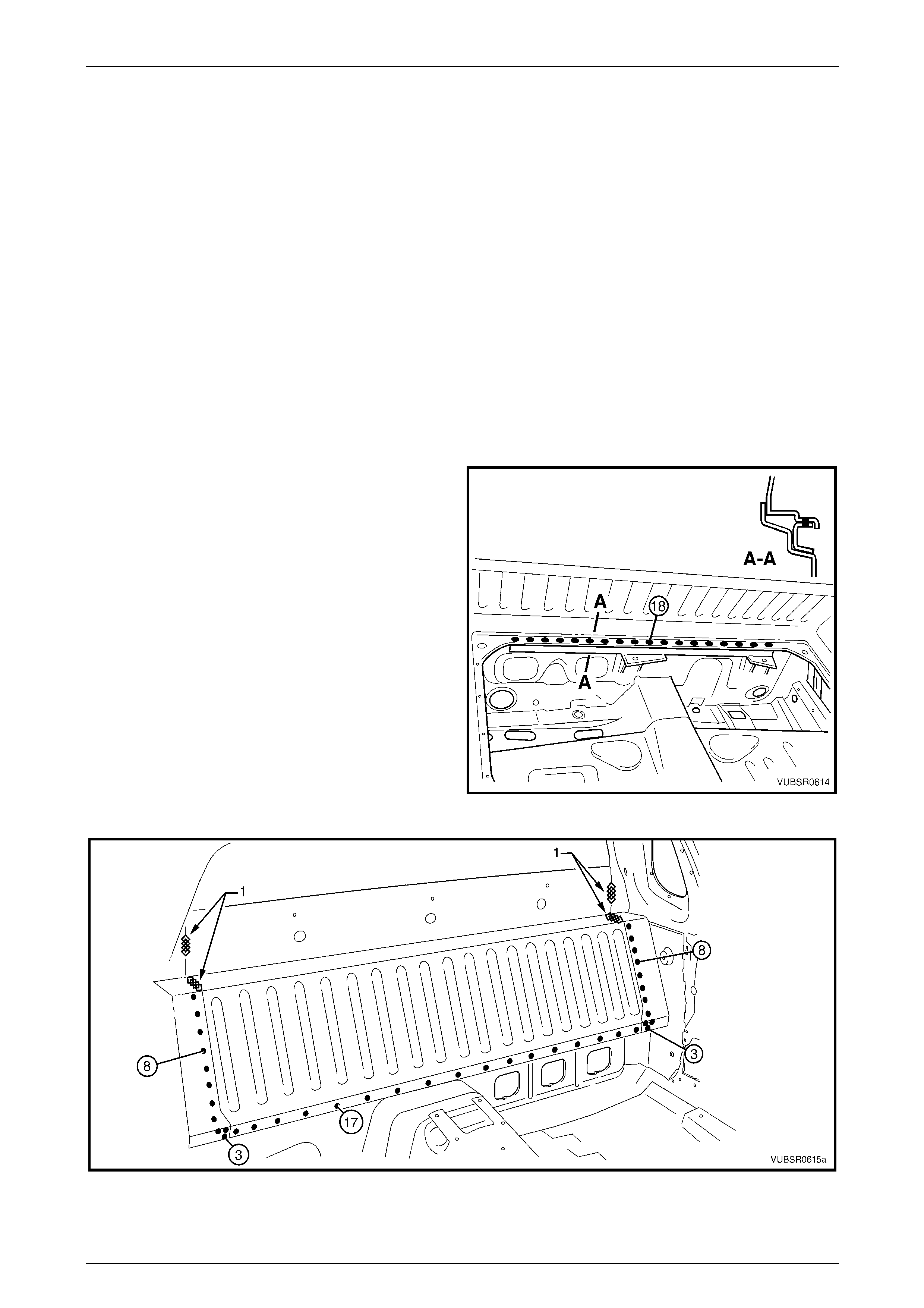
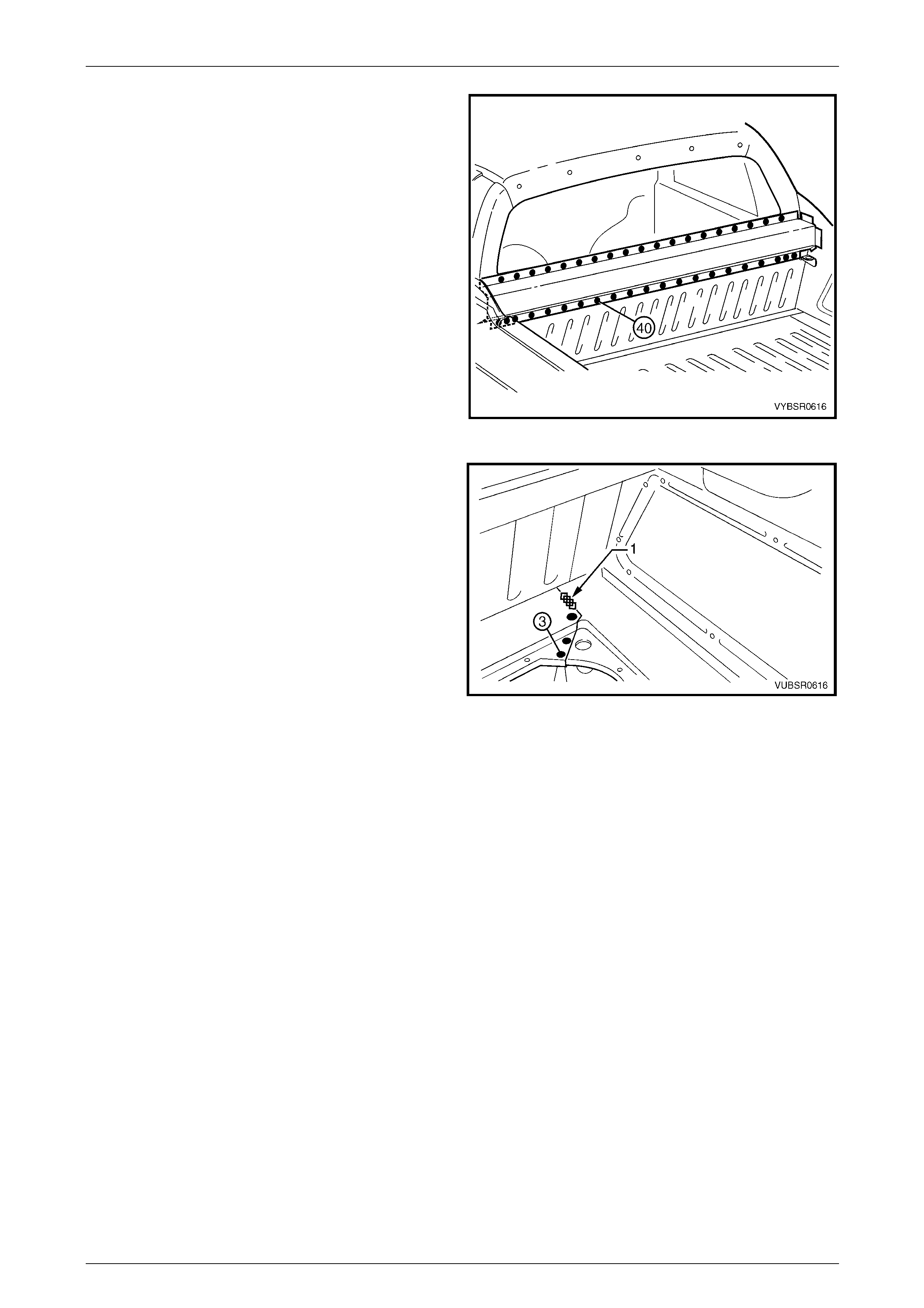
7 If the load compartment extension outer panel upper
was not removed, spot or plug weld the front seatback
panel 40 places.
Figure 6C – 39
8 Spot or plug weld three places and MIG weld 25 mm
one place (1), the front seatback panel to the load floor
panel outer extension.
9 Replace the adjoining removed panels as required,
refer to the relevant Section in this Supplement.
10 Refinish and paint panels and other components as
required. Refer to Section 3 Body Construction .
11 Apply Joint Sealer (Item 3) as required.
Refer to Section 3C Body Construction – Utility.
12 Apply Cavity Wax (Item 8) as required to the inside of
any box sections or areas inaccessible to paint,
refer to Section 3C Body Construction – Utility.
13 Install the rear window, refer to Section 1A6 Stationary
Windows in the MY2005 VZ Service Information.
14 Install the remaining components as described in the
MY2005 VZ Service Information.
Figure 6C – 40
6C Cabin Floor and Seatback Assembly – Utility Page 6C-22
Page 6C-22
2.6 Front Floor Rear Extension Assembly –
Replace
NOTE
This procedure describes r emoving the front floor
rear extension, front floor rear extension
reinforcement and front fuel tank brackets as an
assembly. As the parts are serviced separately,
their installation is described as they would be
replaced.
Remove
1 Remove the adjacent bolt-on panels a nd components
as described in the appropriate Section of the MY2005
VZ Service Information.
2 Secure the vehicle on a suitable fixture and support
the structural sections of the vehicle on safety stands.
3 Remove the adjacent panels as required, refer to the
relevant Section in this Supplement.
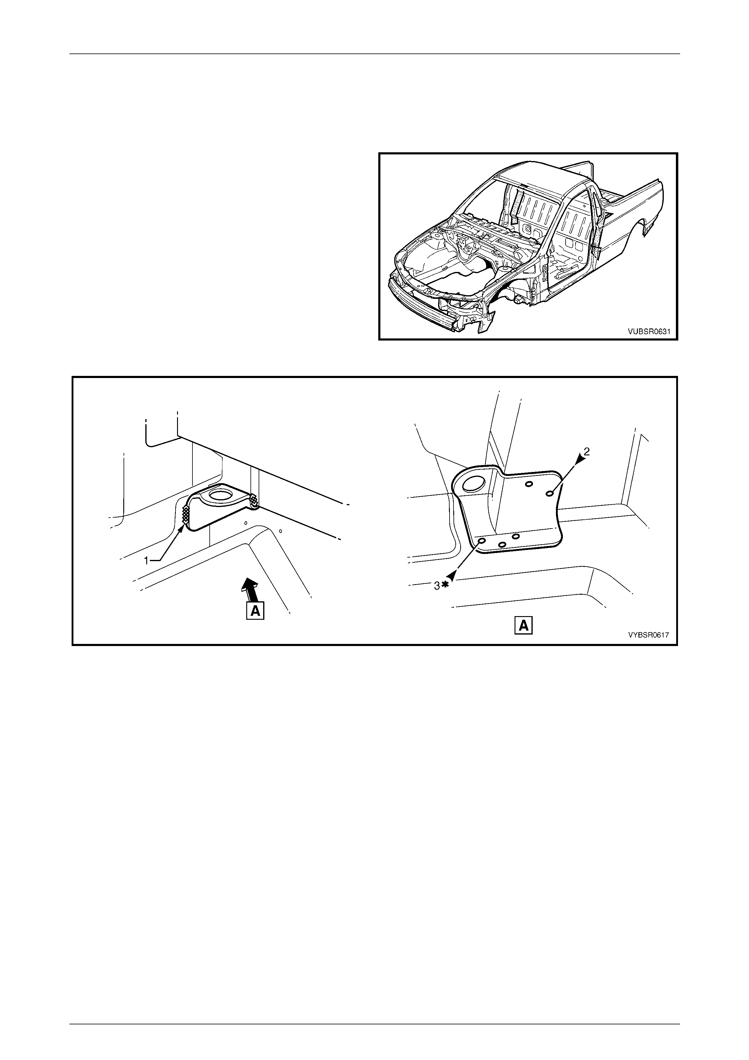
Figure 6C – 41
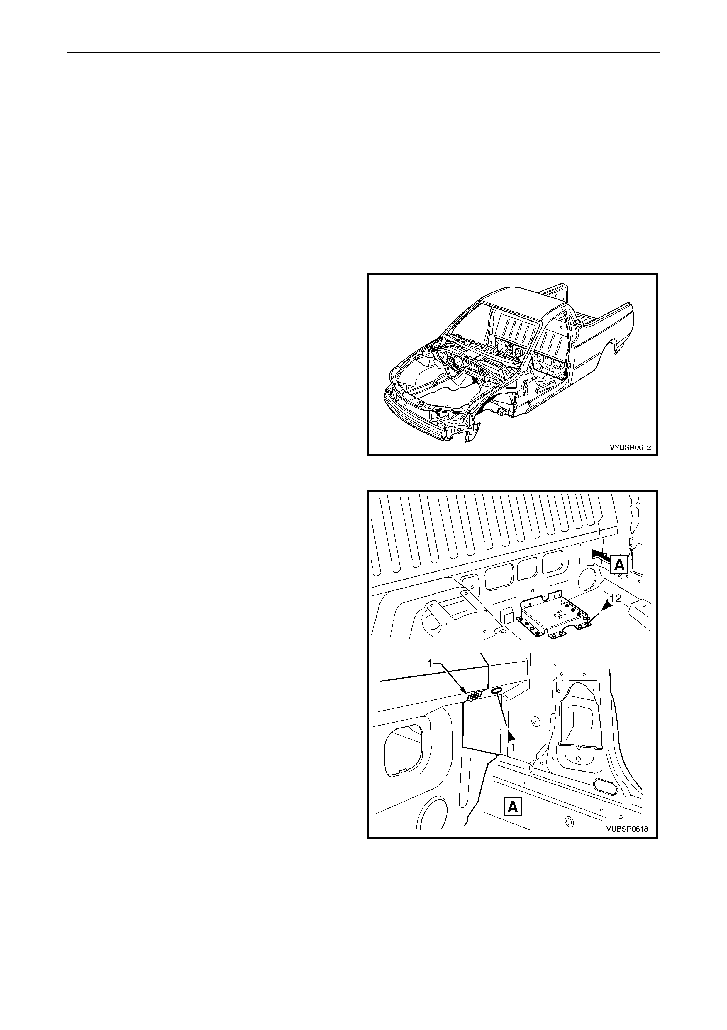
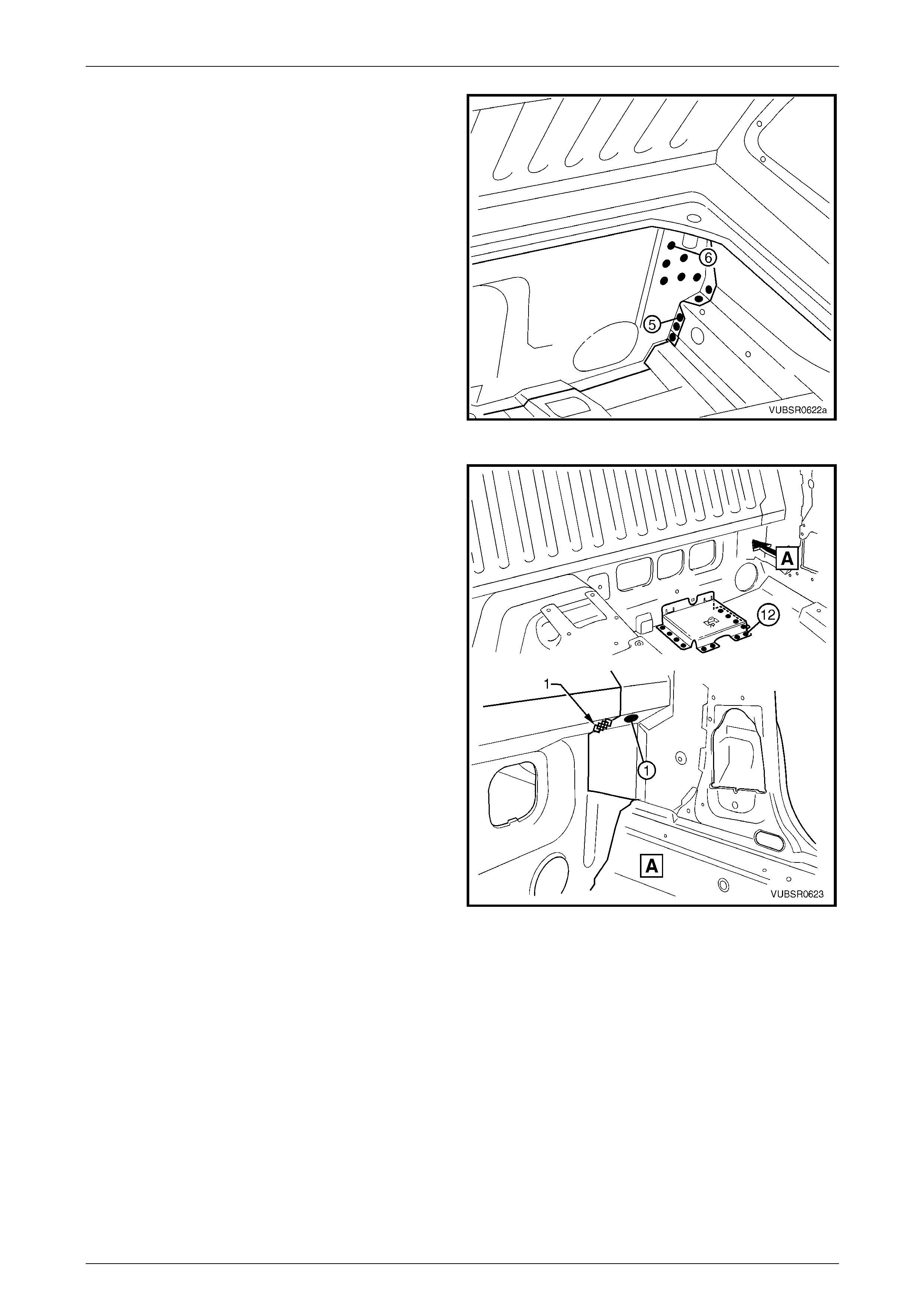
4 If required, spot cut the 12 welds attaching the jack
stowage bracket to the floor.
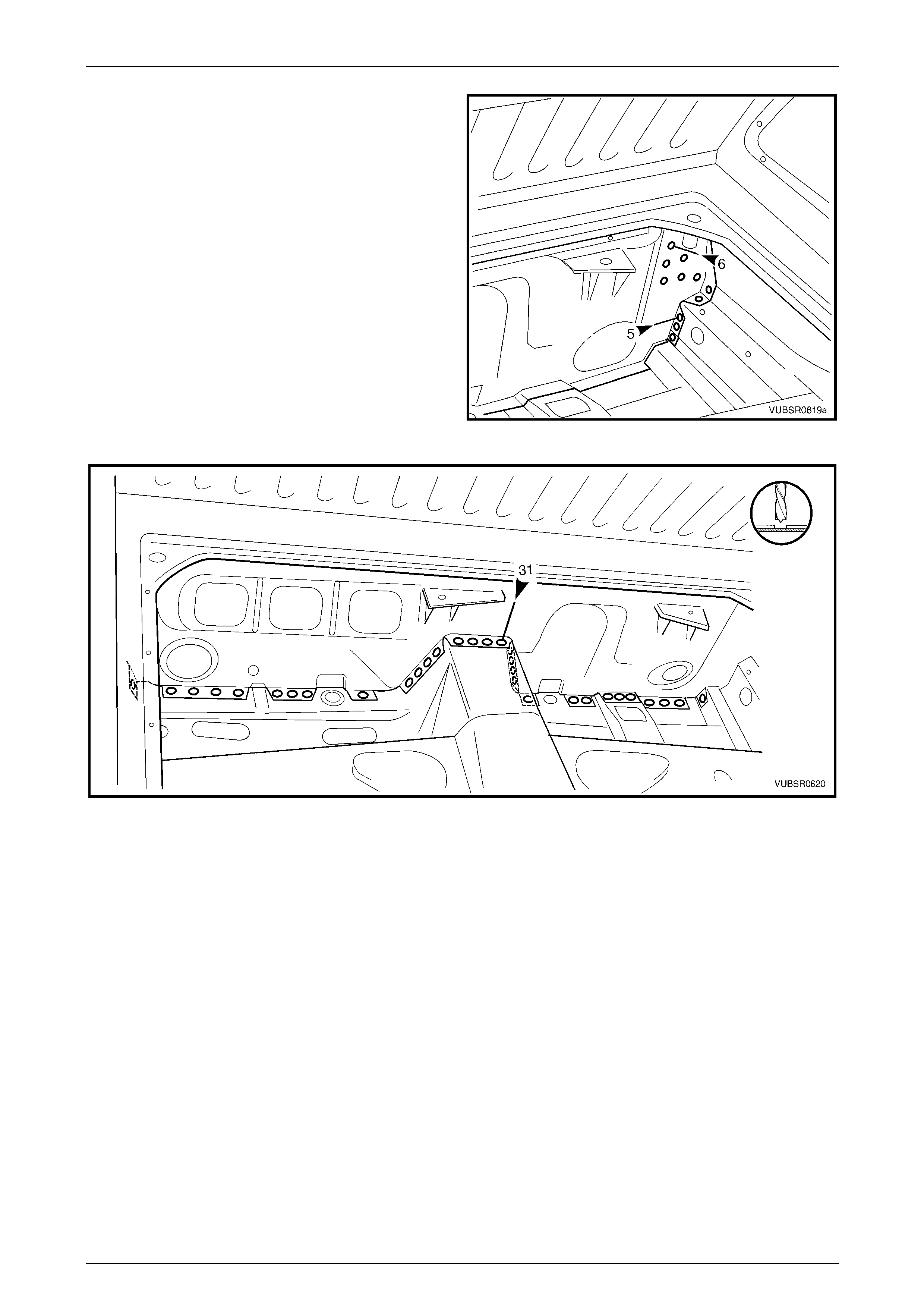
5 Spot cut the weld and grind off the MIG weld (1) each
side, attaching the front floor rear extension to the
front seatback panel outer, refer to View A.
6 If the front seatback panel has not been remo ved,
remove the welds attaching it to the front floor rear
extension, refer 2.5 Front Seatback Panel – Replace
in this Section.
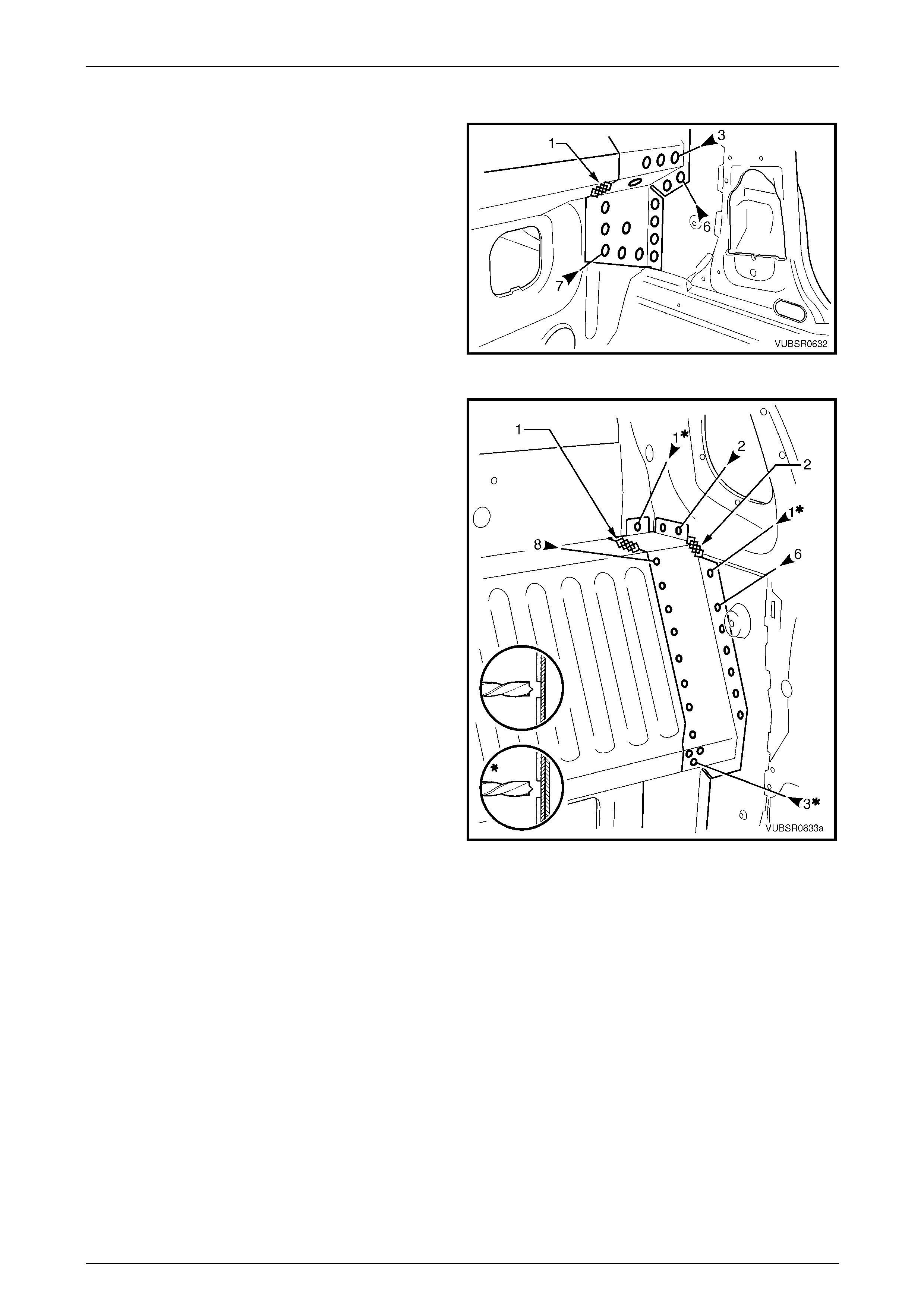
Figure 6C – 42
6C Cabin Floor and Seatback Assembly – Utility Page 6C-23
Page 6C-23
7 Spot cut the welds attaching the front floor rear
extension to the:
a front seatback panel outer, six places each side,
b inner rocker panel, five places each side,
8 Spot cut the 31 welds attaching the front floor rear
extension to the to front floor panel,
refer to Figure 6C – 44.
9 Remove the front floor rear extension assembly from
the vehicle and repair any damage to adjacent panels.
10 Check and rectify the alignme nt of
the body as requir ed,
refer to Section 3C Body Construction – Utility.
Figure 6C – 43
Figure 6C – 44
6C Cabin Floor and Seatback Assembly – Utility Page 6C-24
Page 6C-24
Replace
NOTE
• Spot welding is the preferred method for
attaching of panels and should be used
whenever possible. Where the spot welding
equipment available will not access the
required weld position, a plug weld should be
performed.
• The same number and position of spot welds
(or plug welds) should be used when
replacing the panel, as was used during
manufacture, in order to maintain the original
structural strength of the vehicle.
1 As required, mark the new panels with drilling locations in preparation for plug welding. Drill holes as required.
2 Prepare all mating surfaces and treat with Weld Through Primer (Item 1) as required,
refer to Section 3C Body Construction – Utility.
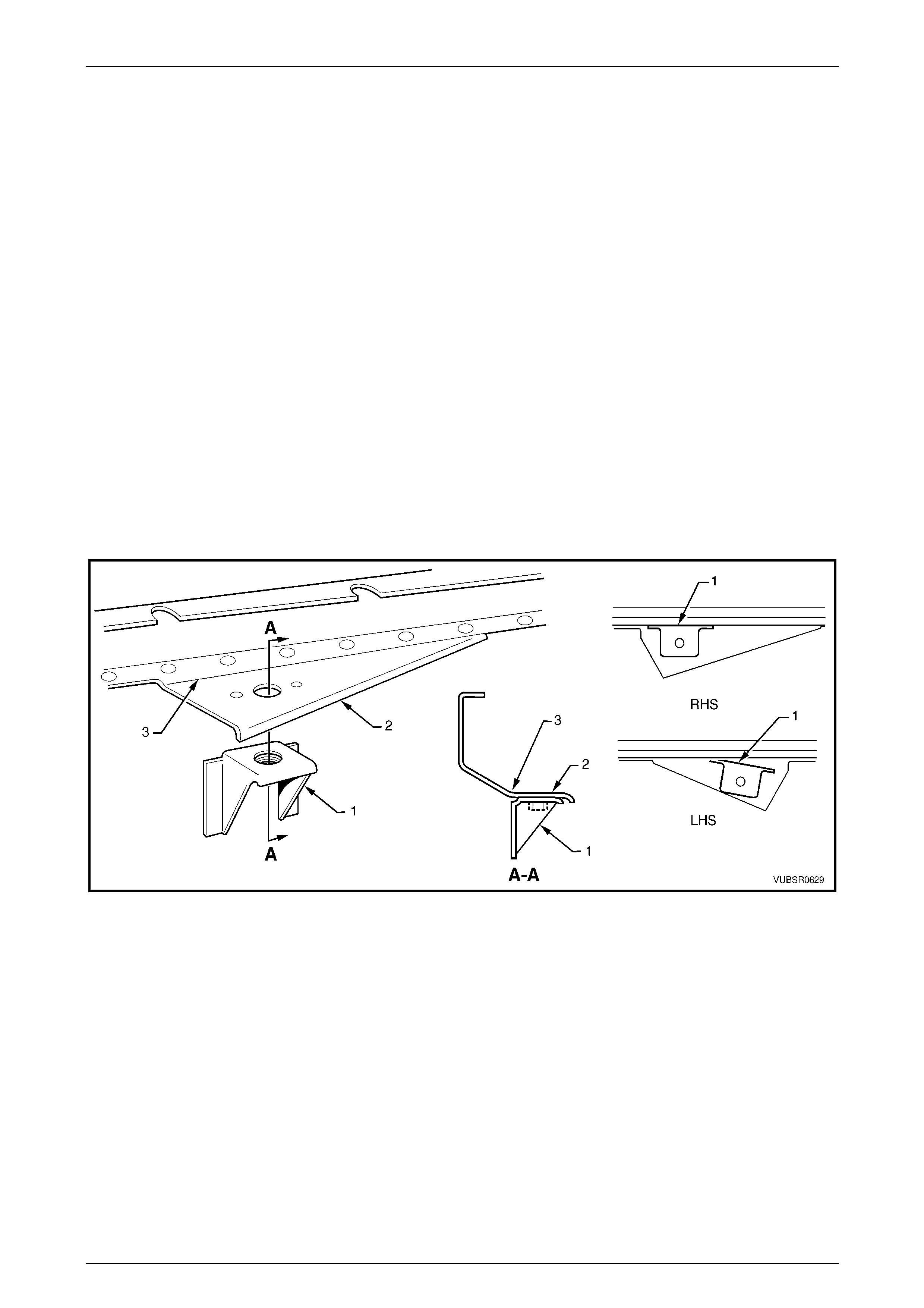
3 Prior to installing the front floor rear extension, fit the left-hand fuel tank bracket (1) on to the front floor rear
extension reinforcement (2) as shown, aligning the fuel tank mounting stud within the reinforcement hole. The
bracket is to be parallel to the fold (3), refer to Figure 6C – 45. Tack weld in position.
4 Repeat for the right-hand fuel tank bracket, noting that it does not sit parallel. Temporarily fit the reinforcement onto
the front floor rear extension to obtain the correct angl e while ensuring the fuel tank mounting stud hole remains
aligned within the reinforcement hole.
Figure 6C – 45
6C Cabin Floor and Seatback Assembly – Utility Page 6C-25
Page 6C-25
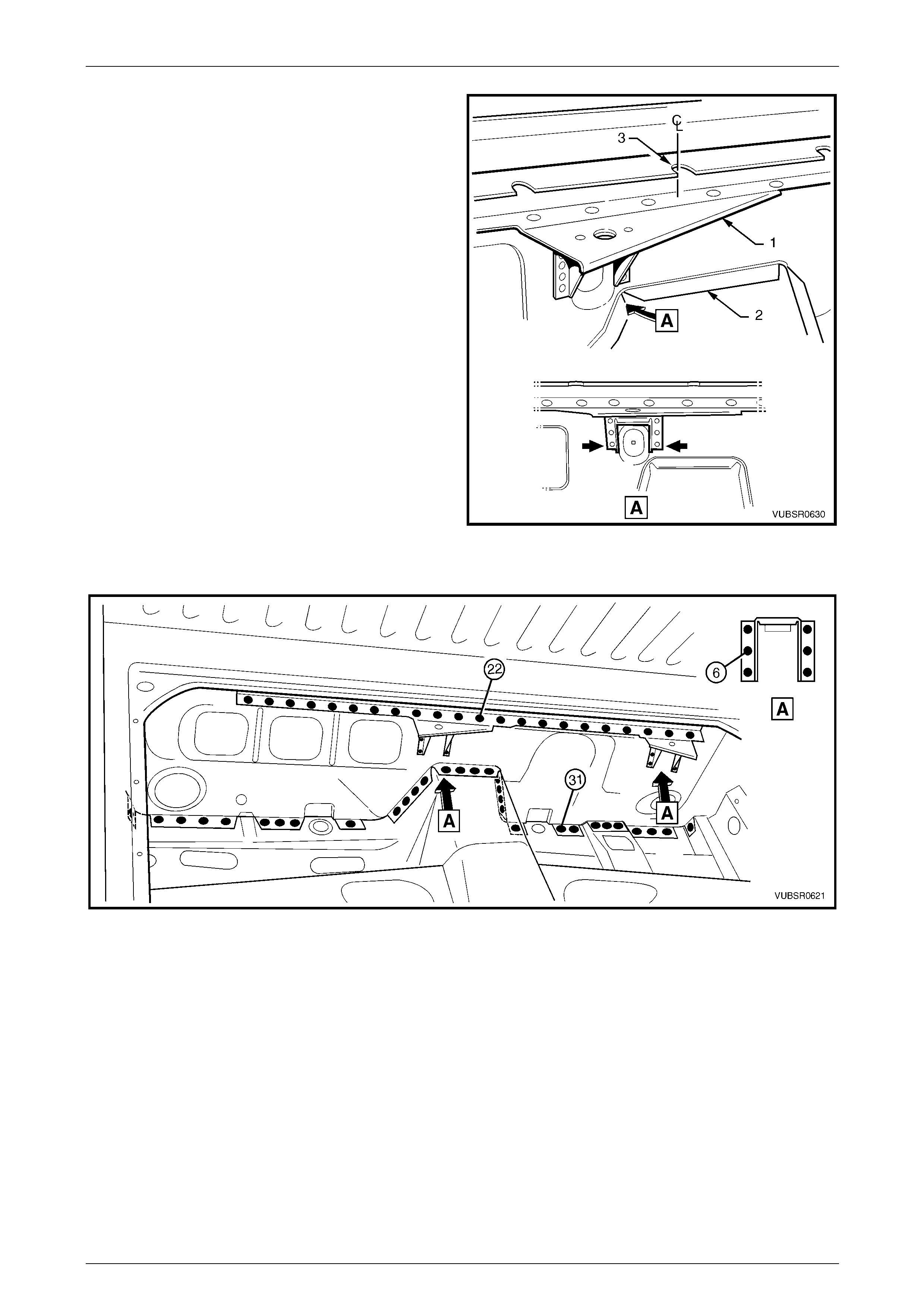
5 Fit the reinforcement and fuel tank bracket assembly
(1) on to the front floor rear extension (2). Position the
left-hand fuel tank bracket over the rib in the front floor
rear extension as shown A. Tack weld the
reinforcement in position.
NOTE
Check the notch in the reinforcement (3) is
central on front floor rear extension assembly.
6 Install and clamp the front floor rear extensi on
assembly in position.
NOTE
Test fit the front seatback panel if it is not
installed, to ensure it seats correctly with the
reinforcement. Also test fit the fuel tank to
ensure it aligns with the mounting studs.
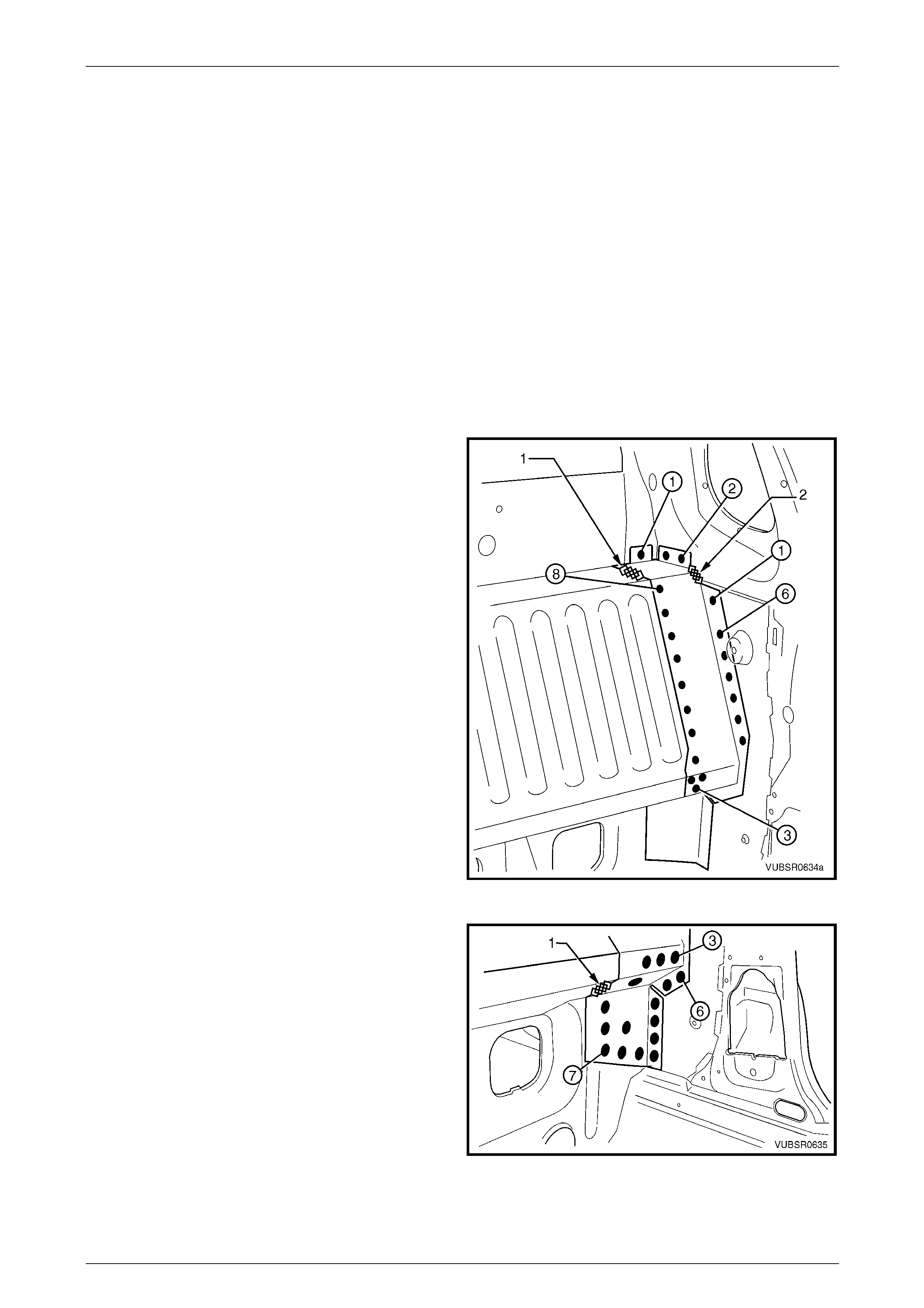
7 Spot or plug weld 31 places, the front floor rear
extension to the floor panel, refer to Figure 6C – 47.
8 Spot or plug weld 22 places, the front floor rear
extension reinf orceme nt to the front floor rea r
extension, refer to Figure 6C – 47.
9 Spot or plug weld six places each, the fuel tank
brackets to the front floor rear extension,
refer to Figure 6C – 47.
Figure 6C – 46
Figure 6C – 47
6C Cabin Floor and Seatback Assembly – Utility Page 6C-26
Page 6C-26
10 Spot or plug weld six places each side, the front floor
rear extension to the to the front seatback panel o uter.
11 Spot or plug weld five places each side, the front floor
rear extension to the to inner rocker panel.
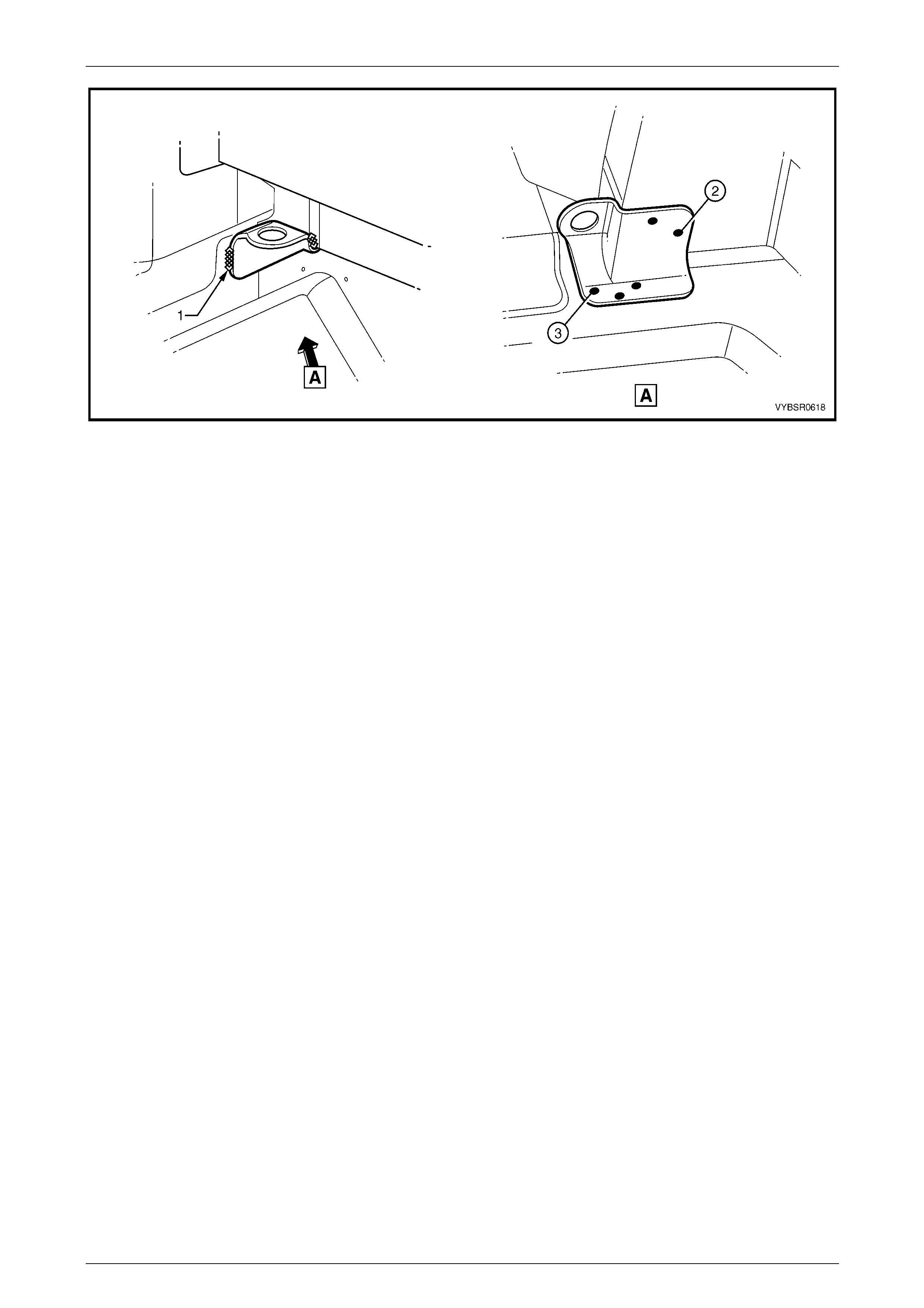
Figure 6C – 48
12 Spot or plug weld one place each side, the front floor
rear extension to the to the front seatback panel outer,
refer to View A.
13 MIG weld 25 mm long, the front floor rear extension to
the to the front seatback panel outer, refer to View A.
14 Spot or plug weld the jack stowage bracket to the floor
panel, if it was removed.
15 Install the front seatback panel if removed,
refer to 2.5 Front Seatback Panel – Replace.
16 Replace the adjoining removed panels as required,
refer to the relevant Section in this Supplement.
17 Refinish and paint panels and other components as
required. Refer to Section 3 Body Construction .
18 Apply Joint Sealer (Item 3) as required.
Refer to Section 3C Body Construction – Utility.
19 Apply Cavity Wax (Item 8) as required to the inside of
any box sections or areas inaccessible to paint,
refer to Section 3C Body Construction – Utility.
20 Install the remaining components as described in the
MY2005 VZ Service Information.
Figure 6C – 49