
6E Cabin Floor – Regular Cab Page 6E–1
Page 6E–1
Section 6E
Cabin Floor – Regular Cab
ATTENTION
Before performing any service operation or other procedure described in this Section, refer to Section 2
Precautions in this Supplement and Section 00 Warnings, Cautions and Notes in the MY2005 VZ Service
Information for correct workshop practices with regard to safety and/or property damage.
The structure of the body shell has been
developed using complex design and
development techniques. In addition to
meeting all required standards, the vehicle
body is also a critical part of the overall safety
systems. It is therefore imperative the repair
procedures described here are adhered to
during all vehicle body repairs.
1 General Information ...............................................................................................................................2
1.1 Cabin Floor Components...................................................................................................................................... 2
2 Service Operations.................................................................................................................................4
2.1 Inner Rocker Panel Assembly – Replace............................................................................................................. 4
Remove................................................................................................................................................................... 4
Replace................................................................................................................................................................... 6
2.2 Rear Body Lower Panel Assembly – Replace ..................................................................................................... 8
Remove................................................................................................................................................................... 8
Replace................................................................................................................................................................. 10
2.3 Rear Body Lower Panel – Replace..................................................................................................................... 12
Remove................................................................................................................................................................. 12
Replace................................................................................................................................................................. 13
2.4 Jack Stowage Bracket – Replace ....................................................................................................................... 15
Remove................................................................................................................................................................. 15
Replace................................................................................................................................................................. 15
2.5 Front Floor Rear Extension – Replace............................................................................................................... 16
Remove................................................................................................................................................................. 16
Replace................................................................................................................................................................. 17
2.6 Front Floor Panel Assembly – Replace.............................................................................................................. 19
Remove................................................................................................................................................................. 19
Replace................................................................................................................................................................. 21
2.7 Transmission Support Bracket, AWD – Replace............................................................................................... 24
Remove................................................................................................................................................................. 24
Replace................................................................................................................................................................. 25
6E Cabin Floor – Regular Cab Page 6E–2
Page 6E–2
1 General Information
With the following exceptions the Re gular Cab Cabin Floor information carries over from Sedan veh icles. For information
not covered in this Section, refer to Section 6A Cabin Floor – Sedan, Wagon, Coupe and AWD W agon .
• Cabin floor components
• Inner rocker panel assembly
• Rear body lower panel ass embly
• Rear body lower panel
• Jack stowage bracket
• Front floor rear extension, left-han d and right-hand
• Front floor panel assembly
• Transmission Support Bracket
Removal of bolt-on panels and mecha nica l components is not covered. For information on the removal of these parts,
reference must be made to the appropriate Section of the MY2005 VZ Service Information.
NOTE
• When repairing the cabin floor of the vehicle,
care must be taken to ensure the structure is
returned to its original production
configuration.
• It is imperative that the correct body
adhesives, sealers, deadeners and cavity
waxes are used when repairing the body
structure, refer to Section 3E Body
Construction – Regular C ab for details of the
correct materials and their commercially
available equivalents.
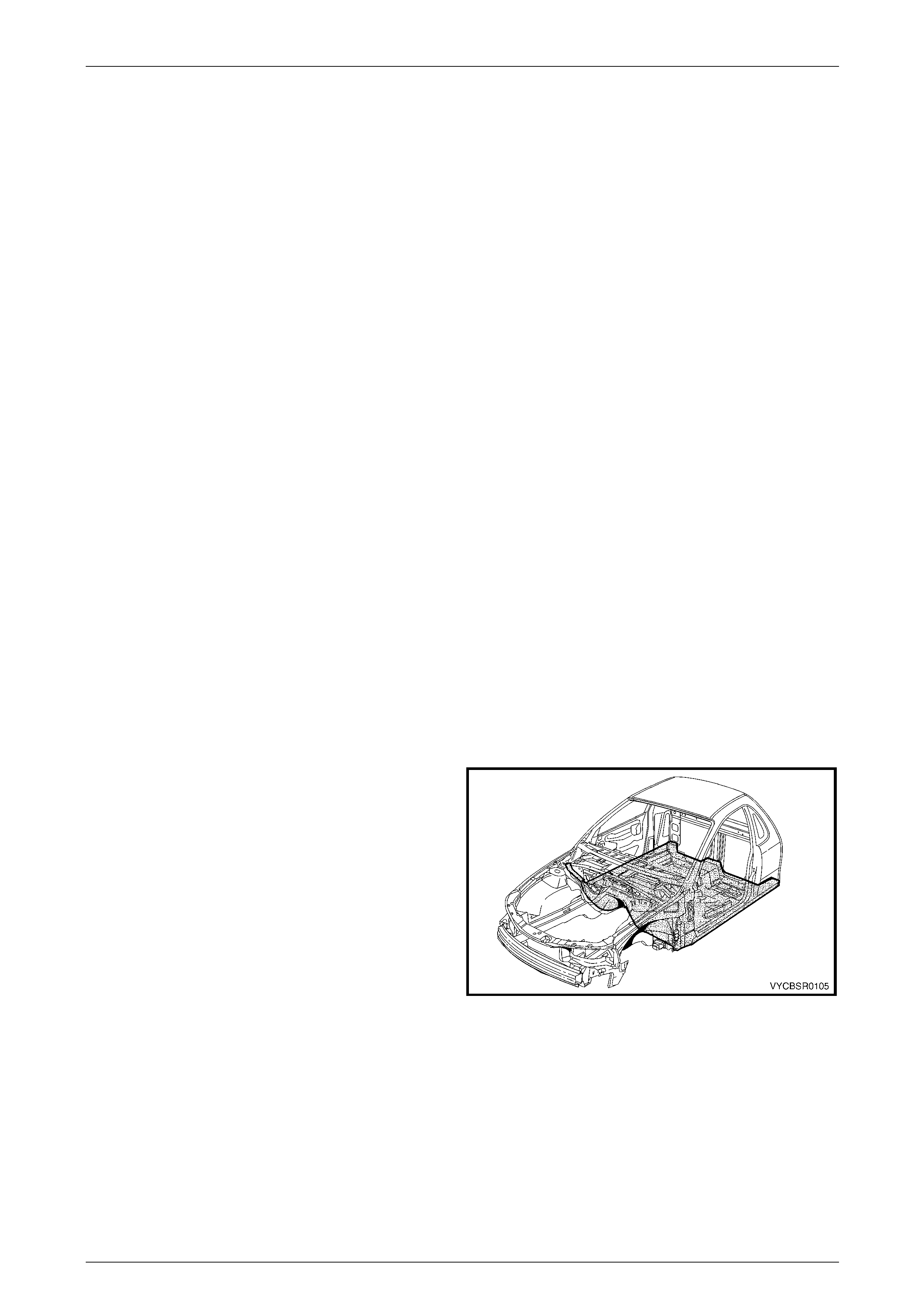
1.1 Cabin Floor Components
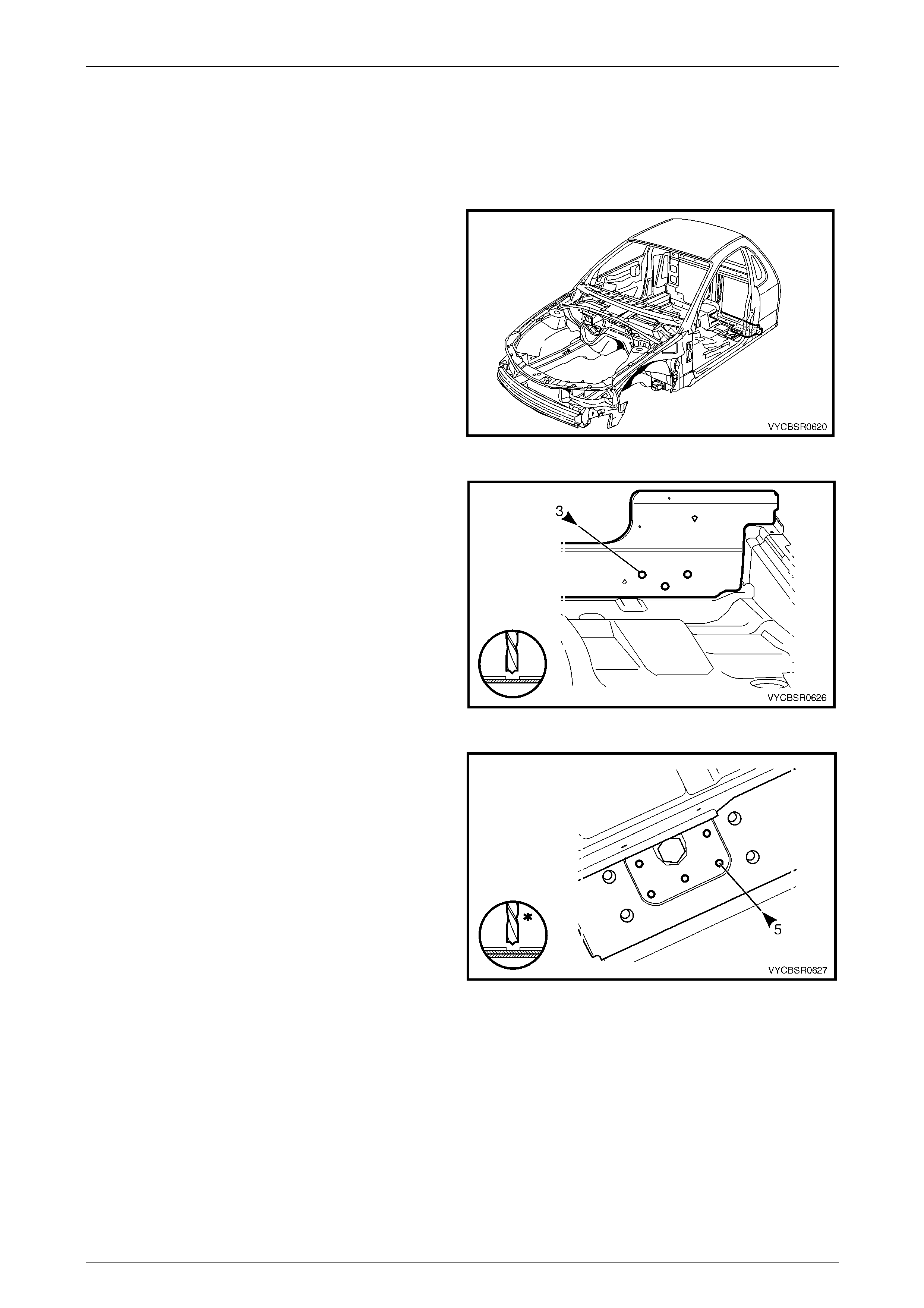
The shaded components are the cabin floor components
dealt with in this Section.
The components and assemblies shown in Figure 6E – 2
are the serviceable parts that form the basis of the repair
procedures in this Section. For a detailed view of the body
components, refer to Section 3E Body Construction –
Regular Cab .
NOTE
Always refer to an Authorised Retailer for spare
parts availability configurations.
Figure 6E – 1
6E Cabin Floor – Regular Cab Page 6E–3
Page 6E–3
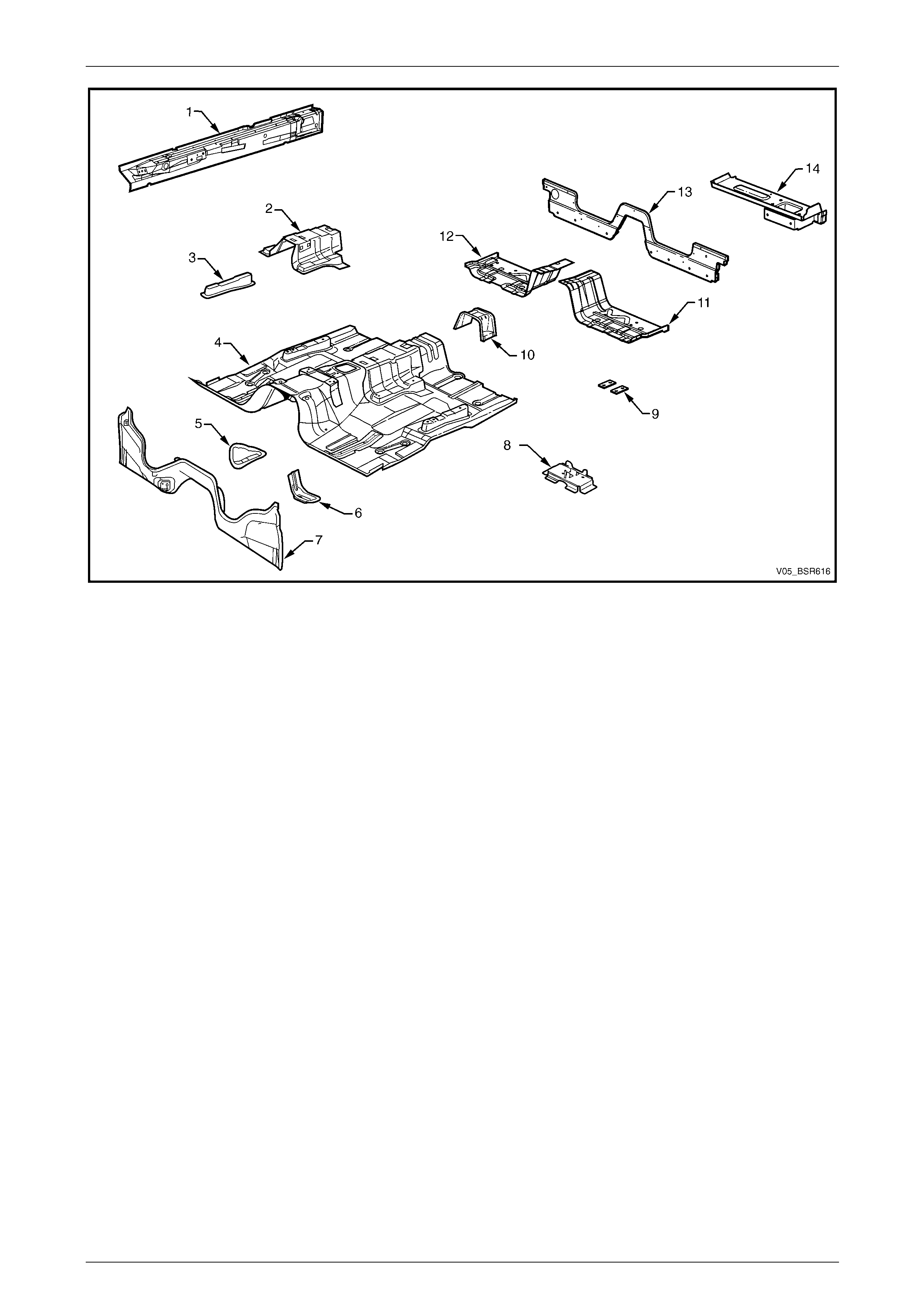
Figure 6E – 2
Legend
1 Inner Rocker Panel Assembly, Left-hand / Right-hand
2 Seat Inner Bracket Assembly*
3 Seat Outer Bracket Assembly, Left-hand/ Right-hand*
4 Front Floor Panel Assembly*
5 Transmission Support Bracket, Left-hand/ Right-hand* #
6 Transmission Support Bracket, Left-hand (AWD only)
7 Front Floor Panel Extension*
8 Jack Stowage Bracket
9 Floor Panel Plate Assembly, two each Left-hand/ Right-
hand*
10 Propeller Shaft Hanger Assembly*
11 Front Floor Rear Extension Panel, Left-hand
12 Front Floor Rear Extension Panel, Right-hand
13 Rear Body Lower Panel
14 Rear Body Lower Panel Assembly, Left-hand/ Right-hand
* For replacement procedures refer to Section 6A Cabin Floor – Sedan, W agon, Coupe and AWD Wagon.
# Right-hand side only for AWD vehicles.
6E Cabin Floor – Regular Cab Page 6E–4
Page 6E–4
2 Service Operations
2.1 Inner Rocker Panel Assembly – Replace
Remove
1 Remove the adjacent bolt-on panels a nd components
as described in the appropriate Section of the MY2005
VZ Service Information.
2 Secure the vehicle on a suitable fixture. As a
minimum, support the structural sections of the vehicle
on safety stands.
3 Remove the door opening frame assembly
and quarter panel inner ass embly,
refer to Section 7E Body Side – Regular Cab.
4 Remove other adjacent pane ls as required, refer to the
relevant Section in this Supplement.
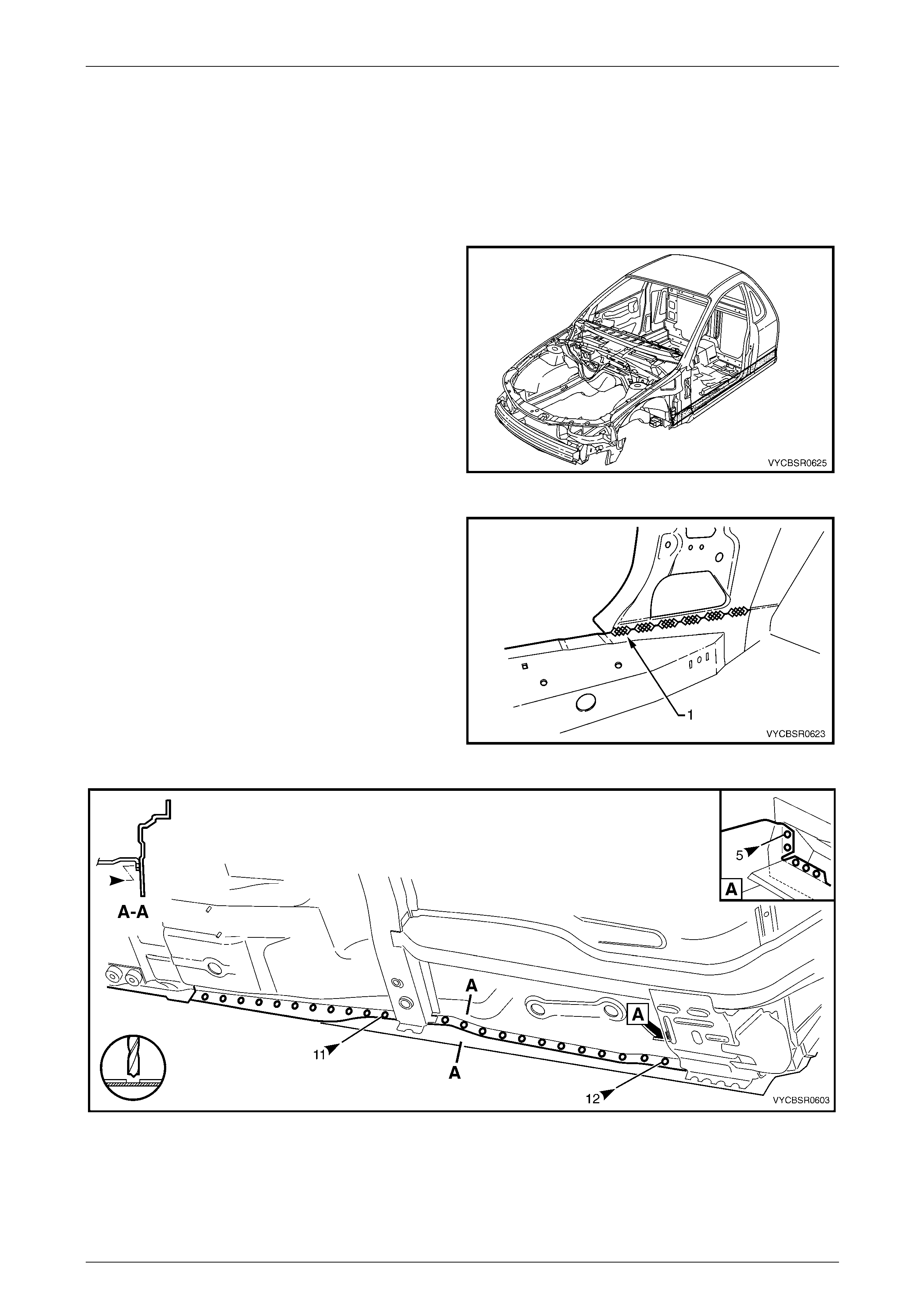
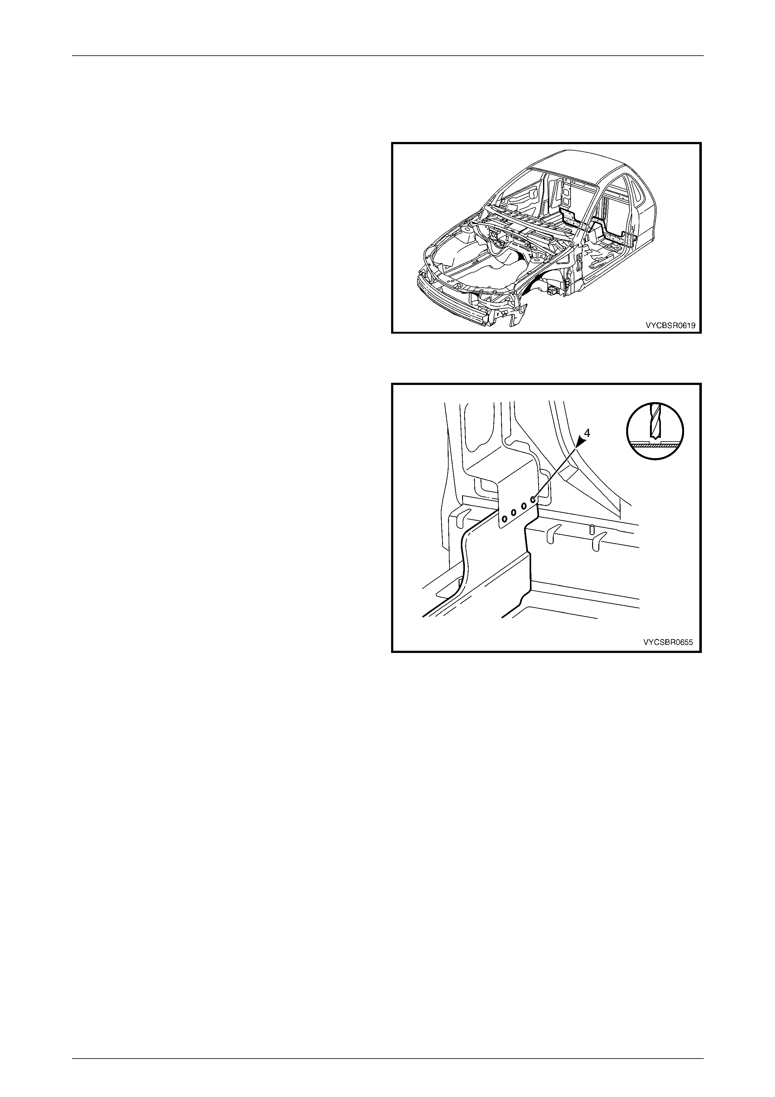
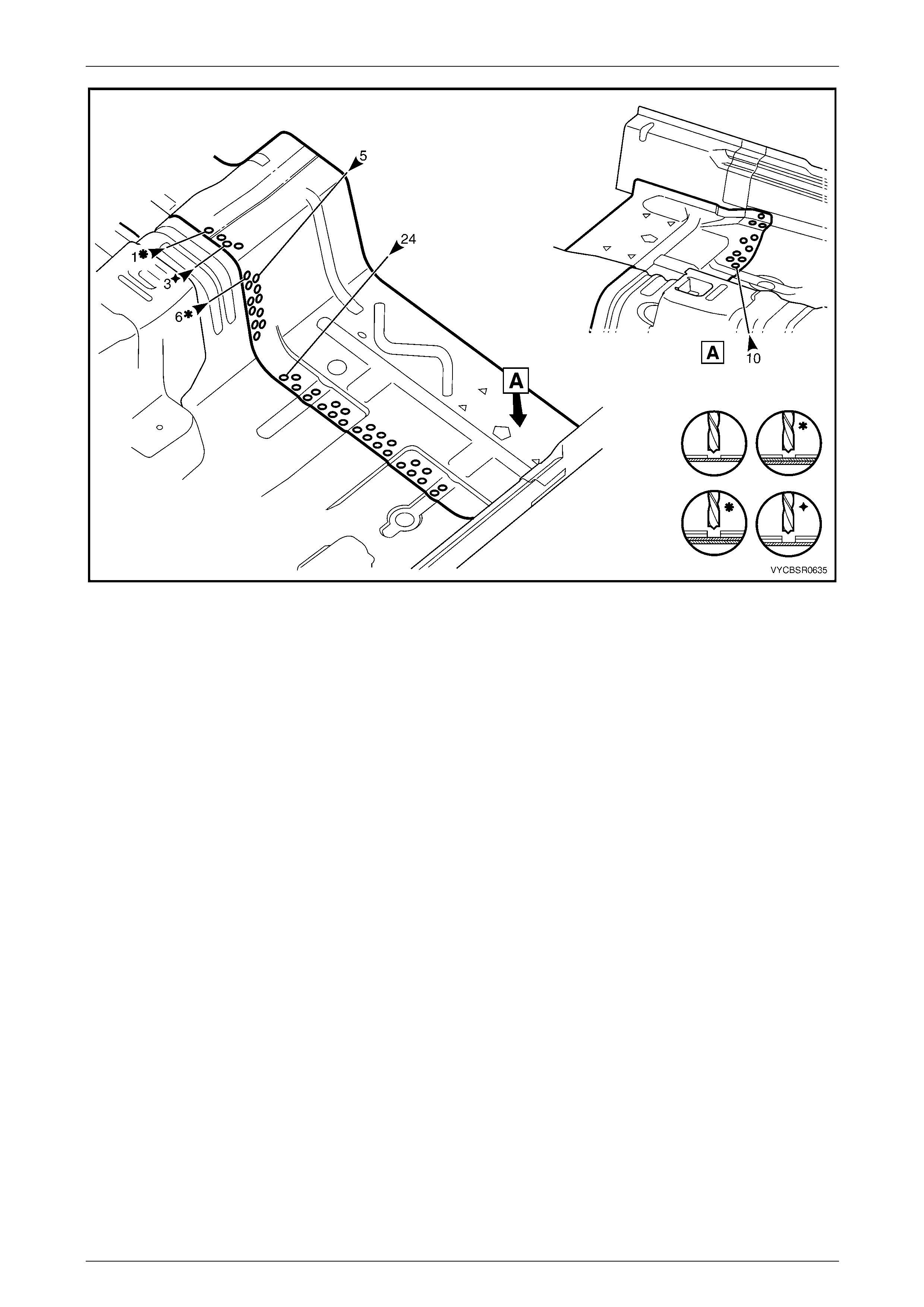
Figure 6E – 3
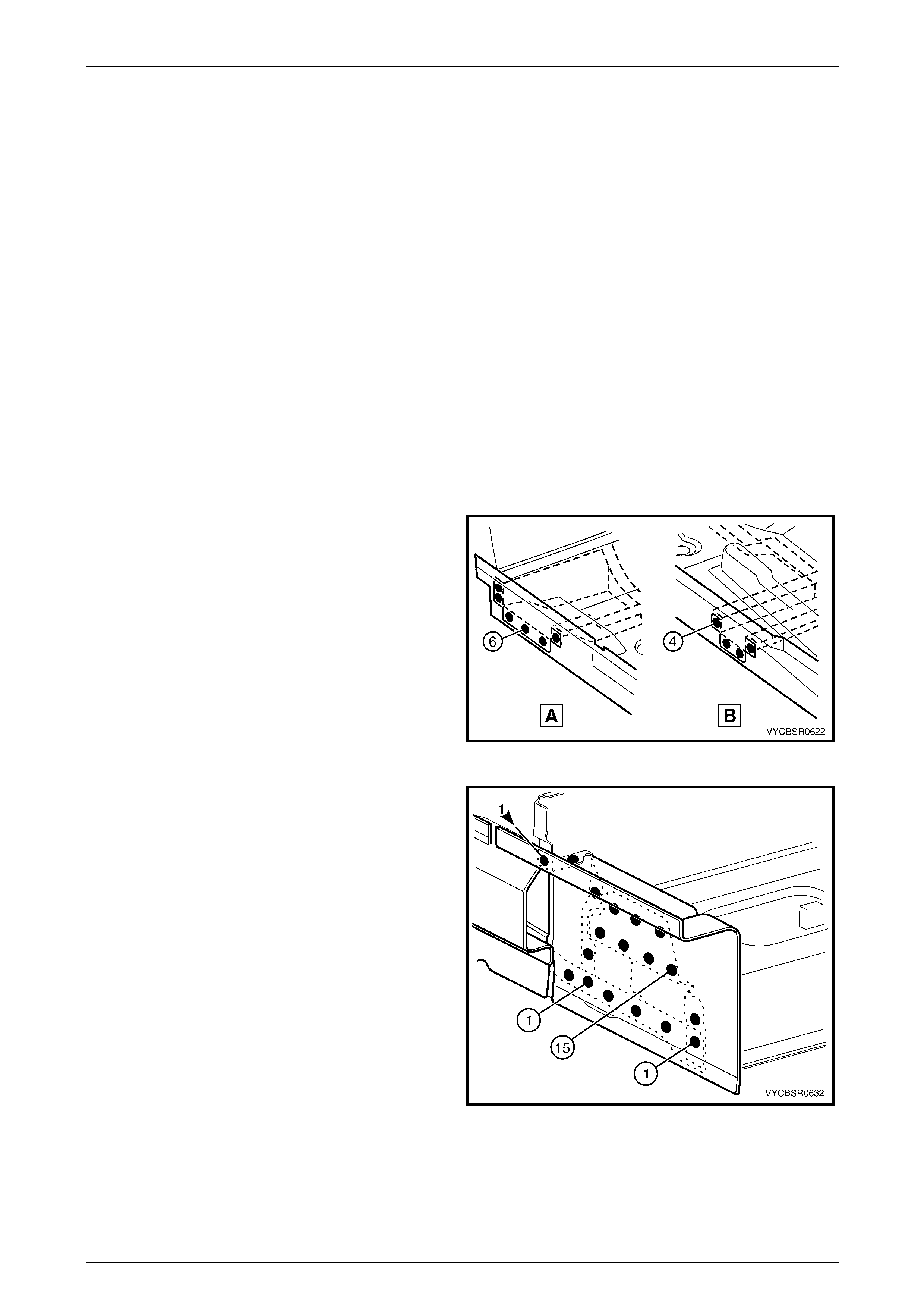
5 Remove the MIG welds (1) attaching the inner rocker
panel to the hinge pillar inner assembly.
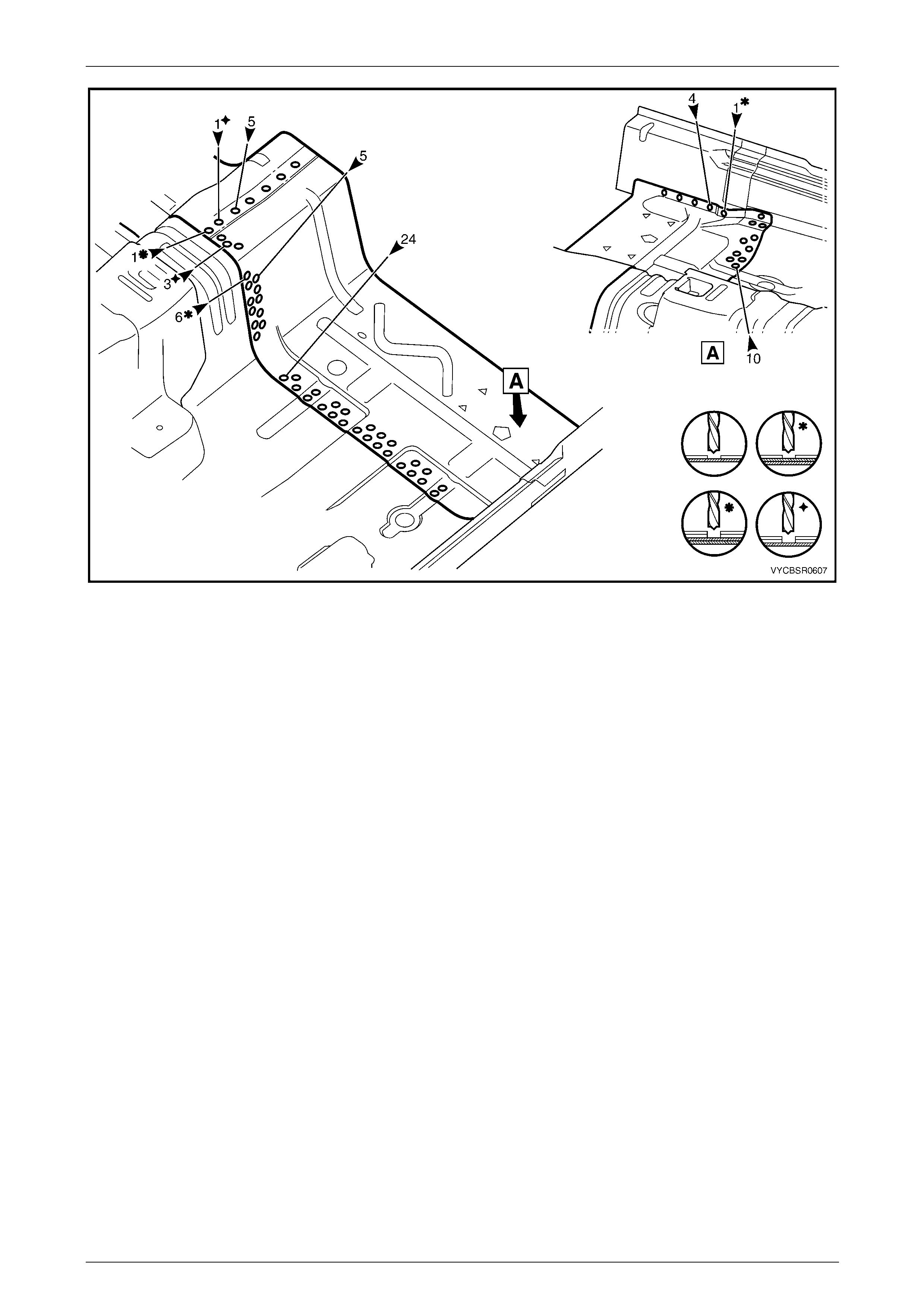
6 From underneath the vehicle, spot cut the welds
attaching the inner rocker panel assembly to the front
floor panel assembly. From inside (A), also spot cut
five welds, refer to Figure 6E – 5.
Figure 6E – 4
Figure 6E – 5
6E Cabin Floor – Regular Cab Page 6E–5
Page 6E–5
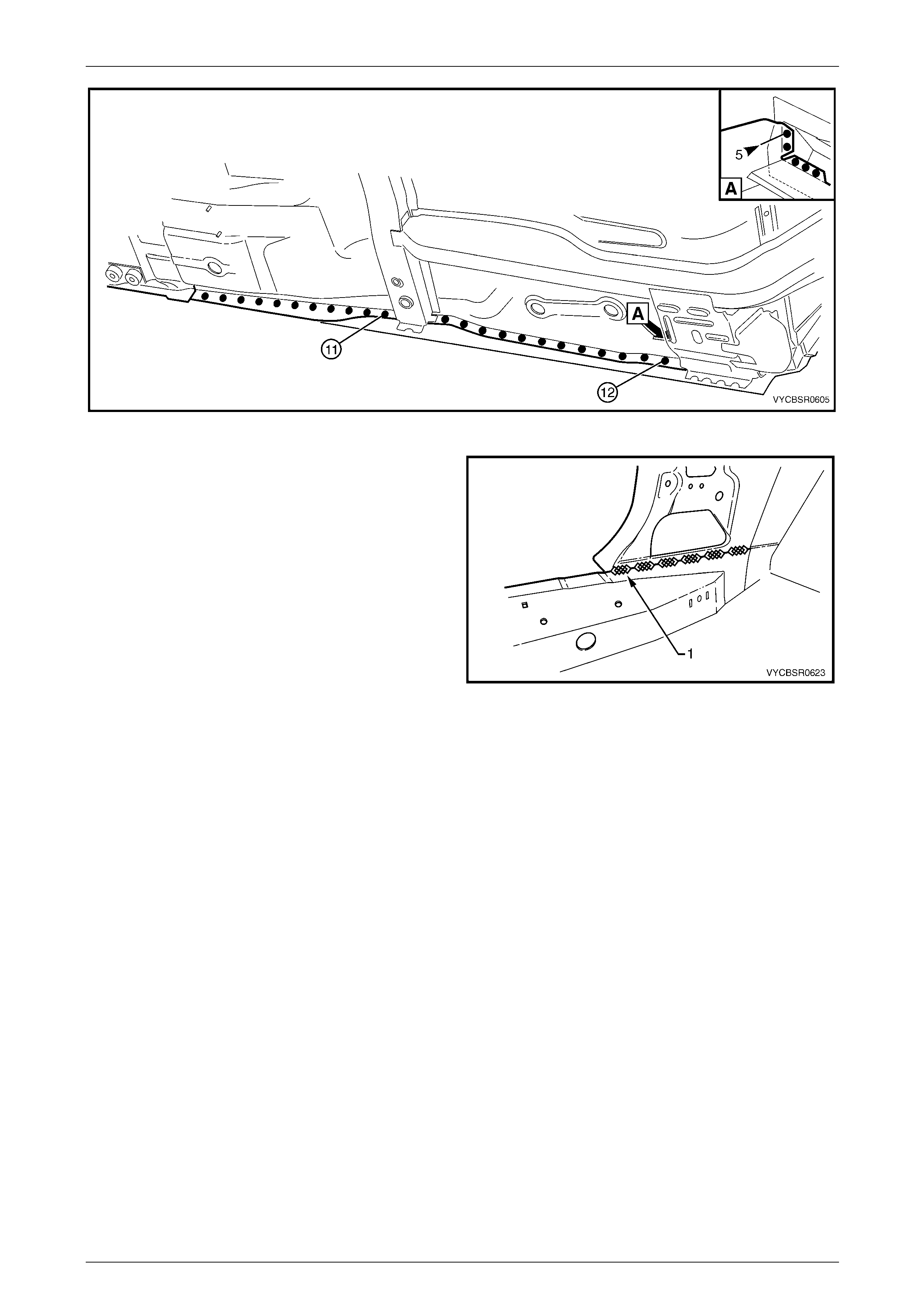
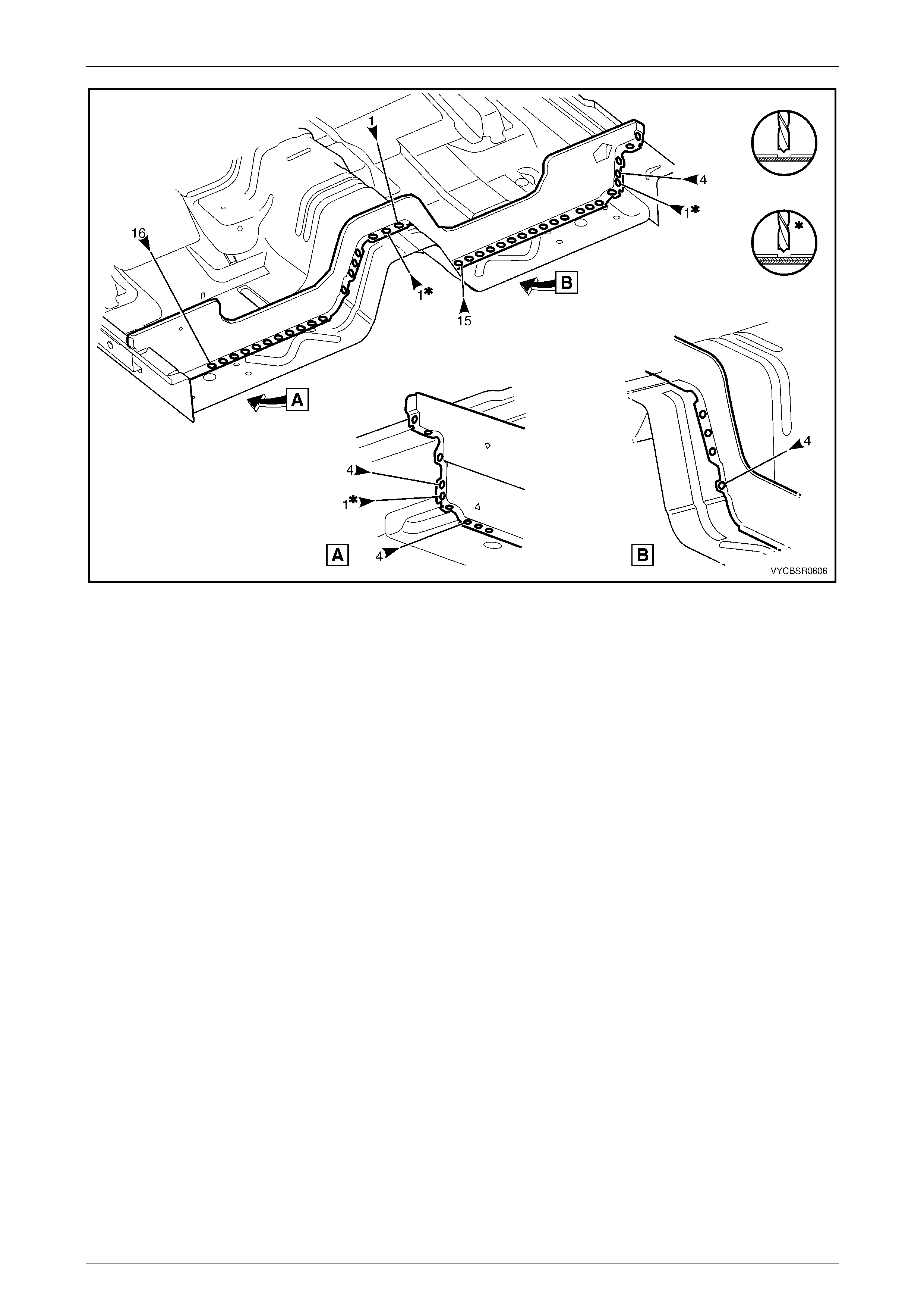
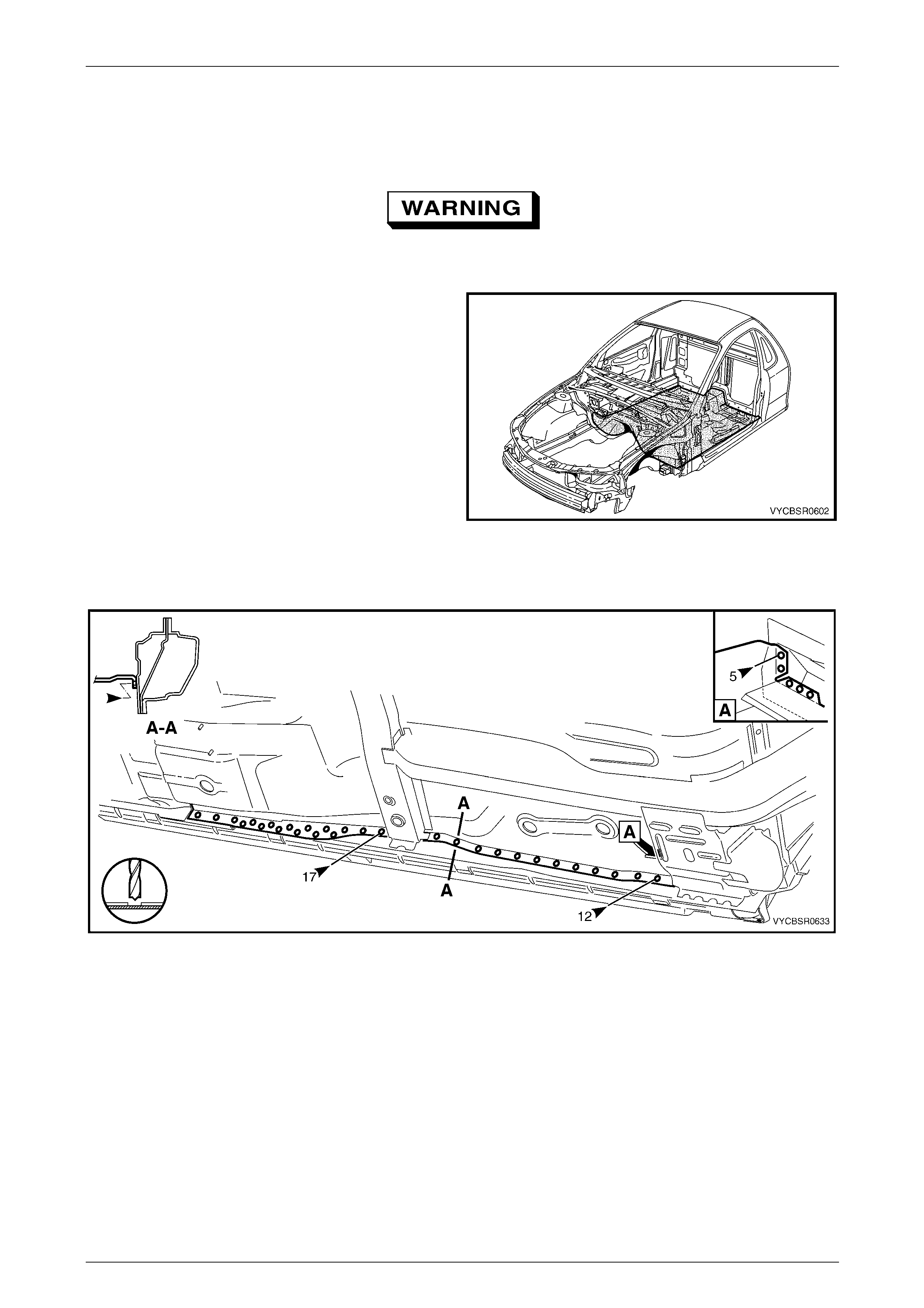
7 Spot cut the welds attaching the rear body lower
panel, the front floor rear extension an d the rear body
lower panel assembly to the inner rocker panel
assembly.
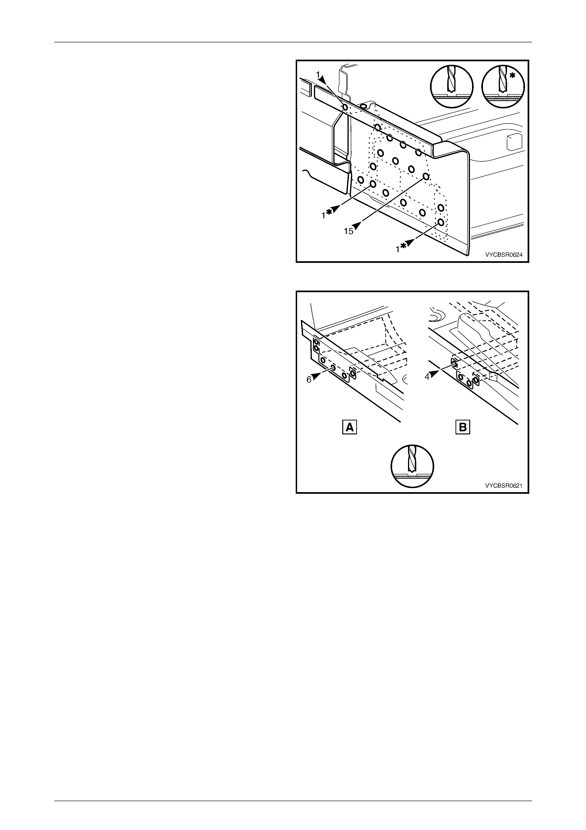
Figure 6E – 6
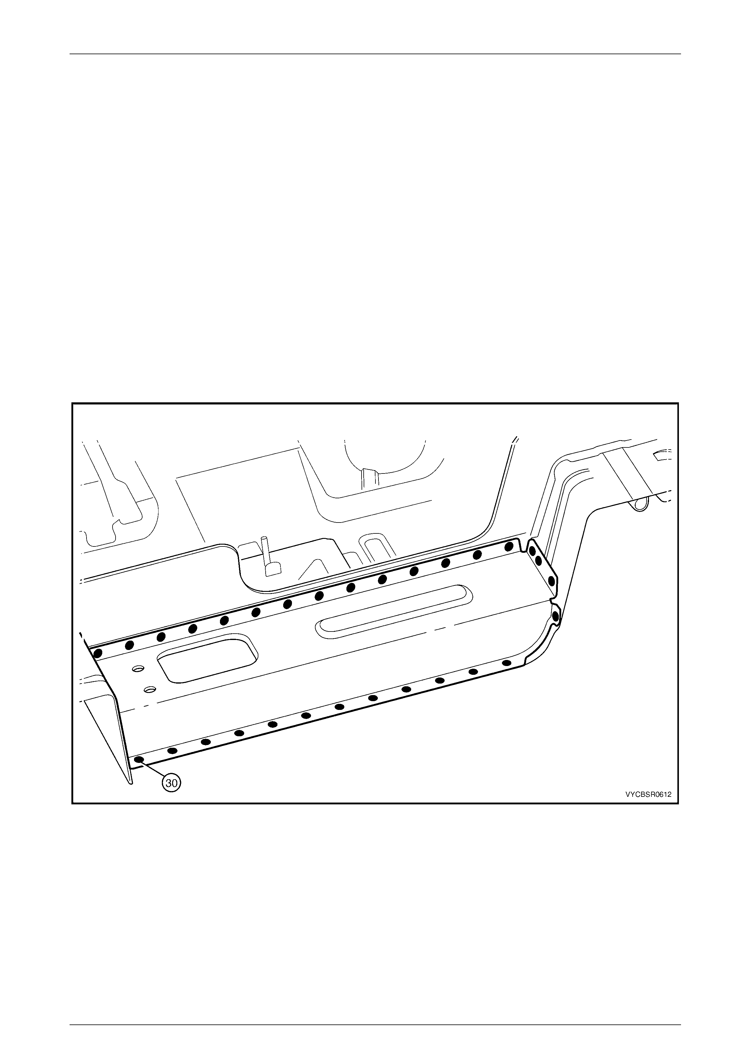
8 Spot cut the welds attaching the inner rocker panel
assembly to the front floor panel support (A), and the
centre crossmember (B).
9 Remove the inner rocker panel assembl y from the
vehicle and repair any damag e to adjacent panels as
required.
10 Check and rectify the alignme nt of
the body as requir ed,
refer to Section 3E Body Construction – Regular Cab .
Figure 6E – 7
6E Cabin Floor – Regular Cab Page 6E–6
Page 6E–6
Replace
NOTE
Spot welding is the preferred method for
attaching of panels and should be used whenever
possible. Where the spot welding equipment
available will not access the required weld
position, a plug weld should be performed.
The same number and position of spot welds (or
plug welds) should be used when replacing the
panel, as was used during manufacture, in order
to maintain the original structural strength of the
vehicle.
1 As required, mark the new panel with drilling locations in preparation for plug welding. Drill holes as required.
2 Prepare all mating surfaces and treat with Weld Through Primer (Item 1) as requir ed,
refer to Section 3E Body Construction – Regular Cab .
3 Apply Acrylic Spot Weld Sealer (Item 2), refer to Section 3E Body Construction – Regular Cab .
4 Clamp the inner rocker panel assembly in position, noting to ensure it fits behind the lower edge of the hinge pillar
inner assembly.
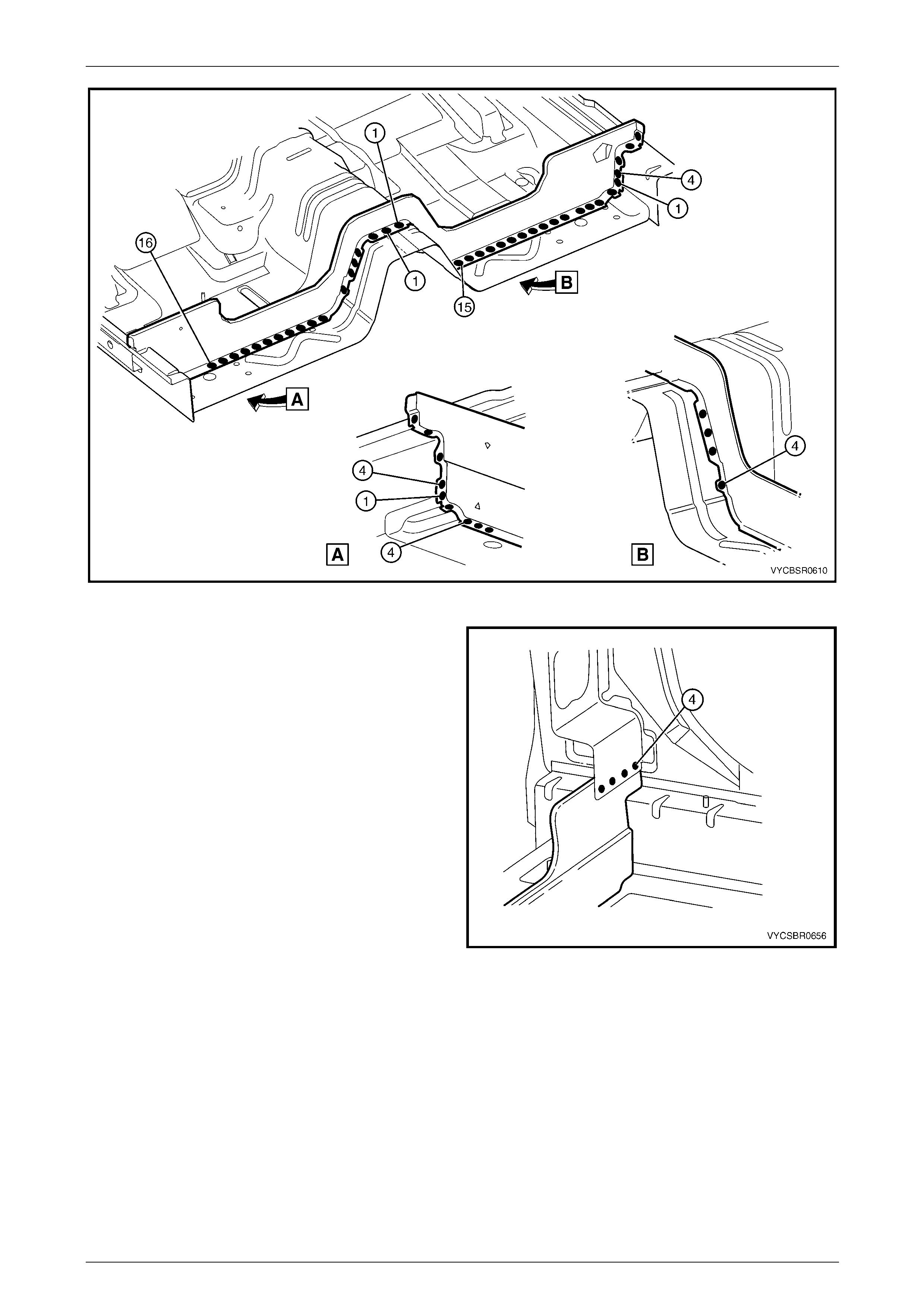
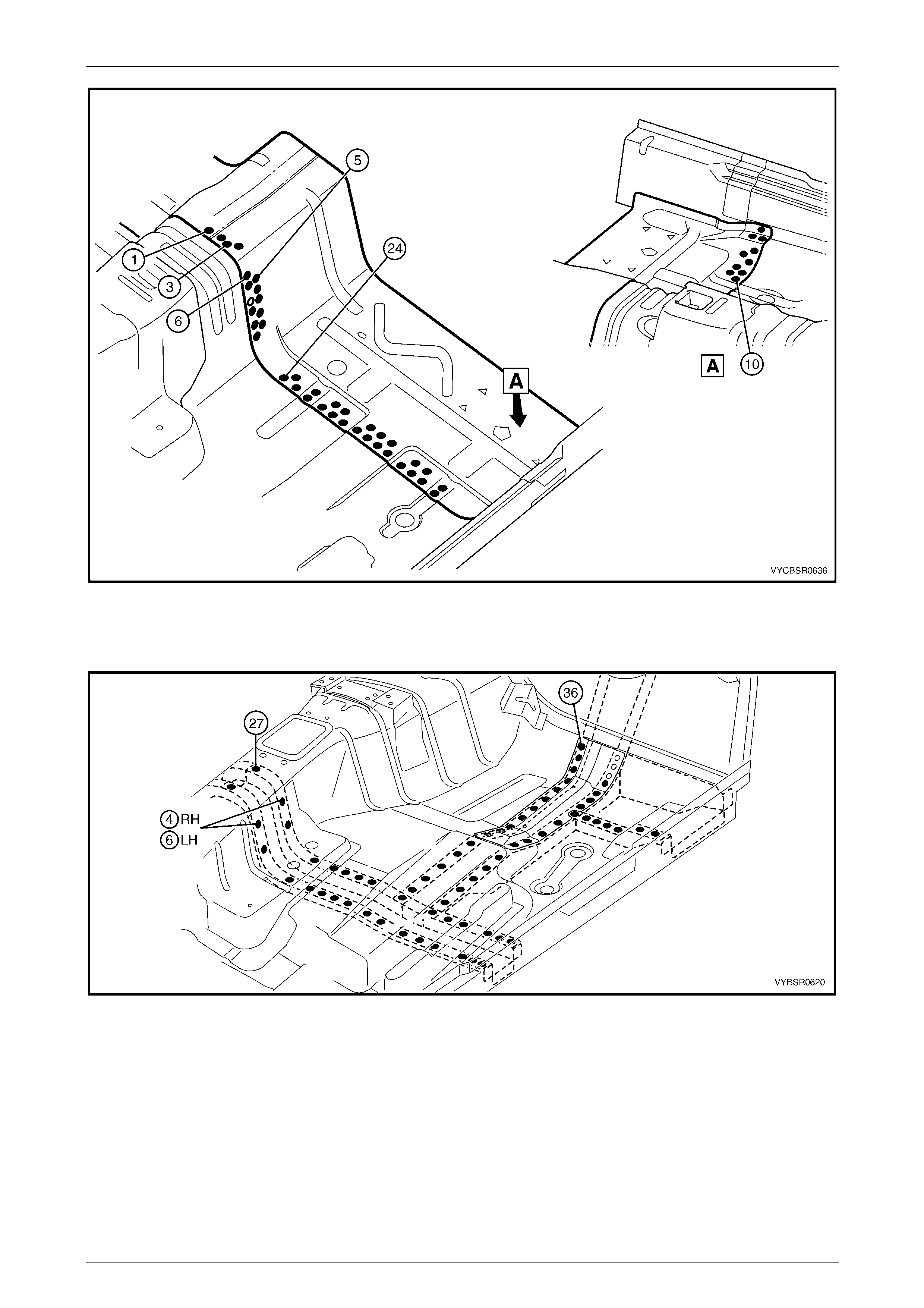
5 Spot or plug weld the inner rocker panel assembly to
the centre crossmember (B) and front floor panel
support (A).
Figure 6E – 8
6 Spot or plug weld the rear body lower panel, the front
floor rear extension and the rear body lower panel
assembly to the inner rocker panel assembly.
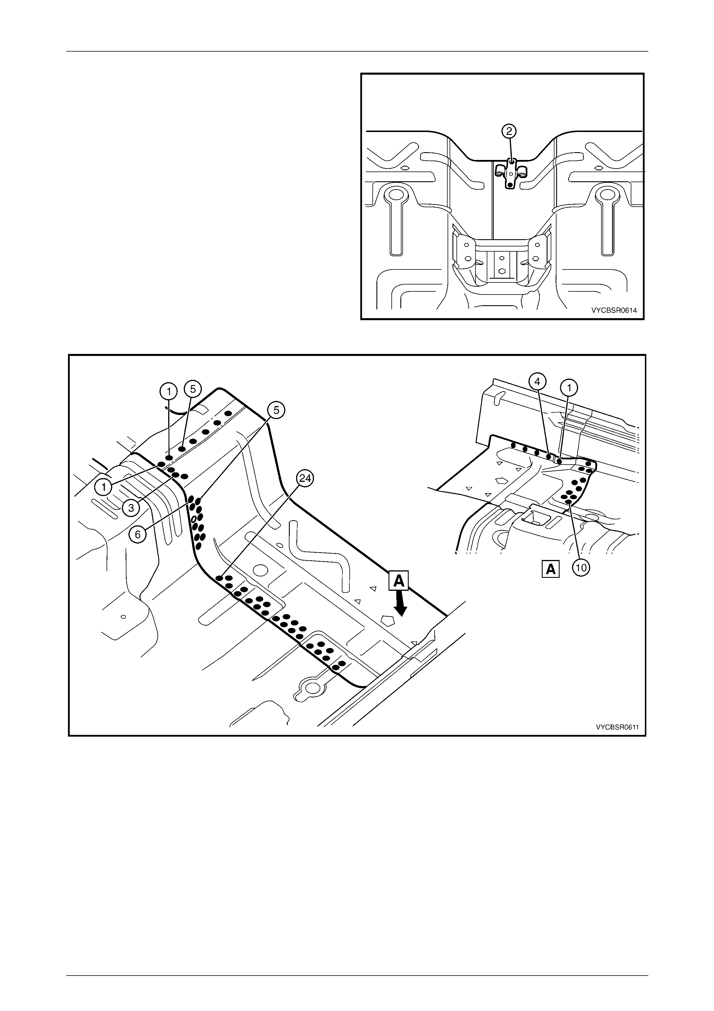
7 From underneath the vehicle, spot or plug weld the
inner rocker panel assembly to the front floor panel
assembly. From inside (A), also spot or plug weld, five
places, refer to Figure 6E – 10.
Figure 6E – 9
6E Cabin Floor – Regular Cab Page 6E–7
Page 6E–7
Figure 6E – 10
8 Make six MIG welds (1) to attach inner rocker panel
assembly to the hinge pillar inner assembly.
9 Replace the adjoining removed panels as required,
refer to the relevant Section in this Supplement.
10 Refinish and paint panels and other components as
required, refer to Section 3 Body Construction.
11 Apply Joint Sealer (Item 3) as required. refer to
Section 3E Body Construction – Regular Ca b .
12 Apply Cavity Wax (Item 8) as required to the inside of
any box sections or areas inaccessible to paint,
refer to Section 3E Body Construction – Regular Cab .
13 Reinstall the remaining bolt-on panels and
components as required, refer to the appropriate
Section of the MY2005 VZ Service Information.
Figure 6E – 11
6E Cabin Floor – Regular Cab Page 6E–8
Page 6E–8
2.2 Rear Body Lower Panel Assembly –
Replace
Remove
1 Remove the adjacent bolt-on panels a nd components
as described in the appropriate Section of the MY2005
VZ Service Information.
2 Secure the vehicle on a suitable fixture. As a
minimum, support the structural sections of the vehicle
on safety stands.
3 Remove other adjacent pane ls as required, refer to the
relevant Section in this Supplement.
Figure 6E – 12
4 Spot cut the welds attaching the rear body lower panel
assembly to the rear body lower panel.
Figure 6E – 13
5 From underneath the vehicle, spot cut the welds
attaching the rear body lower panel assembly to the
front floor rear extension p anel.
Figure 6E – 14

6E Cabin Floor – Regular Cab Page 6E–9
Page 6E–9
6 Spot cut the welds attaching the rear body lower panel
assembly to the inner rocker panel assembly.
7 Spot cut the welds attaching the rear body lower panel
assembly to the rear body lower panel and the front
floor panel rear extension, refer to Figure 6E – 16.
Figure 6E – 15
Figure 6E – 16
8 Remove the rear body lower panel assembly from the vehicle and repair any damage to adjacent panels as
required.
9 Check and rectify the alignme nt of the body as required, ref er to Section 3 E Body Construction – Regular Cab .
6E Cabin Floor – Regular Cab Page 6E–10
Page 6E–10
Replace
NOTE
Spot welding is the preferred method for
attaching of panels and should be used whenever
possible. Where the spot welding equipment
available will not access the required weld
position, a plug weld should be performed.
The same number and position of spot welds (or
plug welds) should be used when replacing the
panel, as was used during manufacture, in order
to maintain the original structural strength of the
vehicle.
1 As required, mark the new panel with drilling locations in preparation for plug welding. Drill holes as required.
2 Prepare all mating surfaces and treat with Weld Through Primer (Item 1) as requir ed,
refer to Section 3E Body Construction – Regular Cab .
3 Apply Acrylic Spot Weld Sealer (Item 2), refer to Section 3E Body Construction – Regular Cab .
4 Spot or plug weld the rear body lower panel assembly to the rear body lower panel and the front floor panel rear
extension, refer to Figure 6E – 17.
Figure 6E – 17

6E Cabin Floor – Regular Cab Page 6E–11
Page 6E–11
5 Spot or plug weld the rear body lower panel assembly
to the inner rocker panel asse mbly.
Figure 6E – 18
6 Spot or plug weld the rear body lower panel assembly
to the front floor panel rear extension.
Figure 6E – 19
7 Spot or plug weld the rear body lower panel assembly
to the rear body lower panel.
8 Replace the adjoining removed panels as required,
refer to the relevant Section in this Supplement.
9 Refinish and paint panels and other components as
required. refer to Section 3 Body Construction.
10 Apply Joint Sealer (Item 3) as required.
refer to Section 3E Body Construction – Regular Cab .
11 Apply Cavity Wax (Item 8) as required to the inside of
any box sections or areas inaccessible to paint,
refer to Section 3E Body Construction – Regular Cab .
12 Reinstall the remaining bolt-on panels and
components as required, refer to the appropriate
Section of the MY2005 VZ Service Information.
Figure 6E – 20
6E Cabin Floor – Regular Cab Page 6E–12
Page 6E–12
2.3 Rear Body Lower Panel – Replace
Remove
1 Remove the adjacent bolt-on panels a nd components
as described in the appropriate Section of the MY2005
VZ Service Information.
2 Secure the vehicle on a suitable fixture. As a
minimum, support the structural sections of the vehicle
on safety stands.
3 Remove the welds attaching the rear body lower
panel, refer to Section 10E Body Rear – Regular Cab.
4 Remove the left-hand and right-hand rear
body lower panel assem blies,
refer to 2.2 Rear Body Lower Panel Assembly –
Replace.
5 Remove other adjacent pane ls as required, refer to the
relevant Section in this Supplement. Figure 6E – 21
6 Spot cut the welds attaching the rear body lower panel
to the quarter panel inner assembly.
7 Spot cut the welds attaching the rear body lower panel
to the front floor panel rear extension and the inner
rocker panel assembly, refer to Figure 6E – 23.
Figure 6E – 22
6E Cabin Floor – Regular Cab Page 6E–13
Page 6E–13
Figure 6E – 23
8 Remove the rear body lower panel from the vehicle and repair any damage to adjacent panels as required.
9 Check and rectify the alignme nt of the body as required, ref er to Section 3 E Body Construction – Regular Cab .
Replace
NOTE
Spot welding is the preferred method for
attaching of panels and should be used whenever
possible. Where the spot welding equipment
available will not access the required weld
position, a plug weld should be performed.
The same number and position of spot welds (or
plug welds) should be used when replacing the
panel, as was used during manufacture, in order
to maintain the original structural strength of the
vehicle.
1 As required, mark the new panel with drilling locations in preparation for plug welding. Drill holes as required.
2 Prepare all mating surfaces and treat with Weld Through Primer (Item 1) as requir ed,
refer to Section 3E Body Construction – Regular Cab .
3 Apply Acrylic Spot Weld Sealer (Item 2), refer to Section 3E Body Construction – Regular Cab .
4 Plug or spot weld the rear body lower panel to the front floor pane l rear extension and the inner rocker panel,
refer to Figure 6E – 24.
6E Cabin Floor – Regular Cab Page 6E–14
Page 6E–14
Figure 6E – 24
5 Plug or spot weld the rear body lower panel to the
quarter panel inner assembly.
6 Replace the adjoining removed panels as required,
refer to the relevant Section in this Supplement.
7 Refinish and paint panels and other components as
required. refer to Section 3 Body Construction.
8 Apply Joint Sealer (Item 3) as required.
refer to Section 3E Body Construction – Regular Cab .
9 Apply Cavity Wax (Item 8) as required to the inside of
any box sections or areas inaccessible to paint,
refer to Section 3E Body Construction – Regular Cab .
10 Reinstall the remaining bolt-on panels and
components as required, refer to the appropriate
Section of the Cab Service Information.
Figure 6E – 25
6E Cabin Floor – Regular Cab Page 6E–15
Page 6E–15
2.4 Jack Stowage Bracket – Replace
Remove
1 Remove the adjacent bolt-on panels a nd components
as described in the appropriate Section of the MY2005
VZ Service Information.
2 Secure the vehicle on a suitable fixture. As a
minimum, support the structural sections of the vehicle
on safety stands.
3 Remove other adjacent pane ls as required, refer to the
relevant Section in this Supplement.
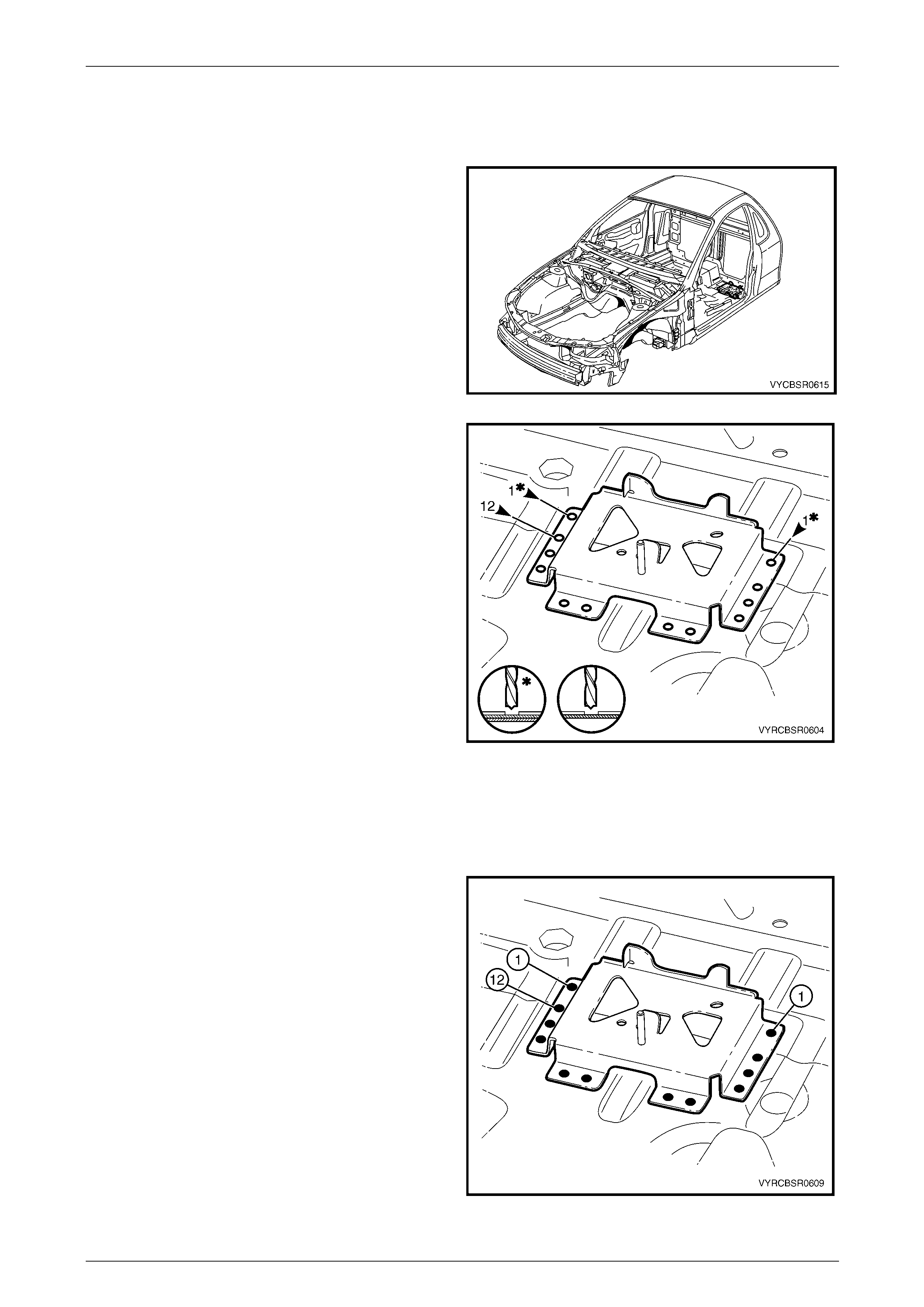
Figure 6E – 26
4 Spot cut the welds attaching the jack stowage bracket
to the front floor panel assembly.
5 Remove the jack stowage bracket from the vehicle
and repair any damage to adjacent panels as required.
Figure 6E – 27
Replace
1 As required, mark the new panel with drilling locations in preparation for plug welding. Drill holes as required.
2 Prepare all mating surfaces and treat with Weld Through Primer (Item 1) as requir ed,
refer to Section 3E Body Construction – Regular Cab .
3 Spot or plug weld the jack stowage bracket to the front
floor panel assembly.
4 Replace the adjoining removed panels as required,
refer to the relevant Section in this Supplement.
5 Refinish and paint panels and other components as
required. refer to Section 3 Body Construction.
6 Apply Joint Sealer (Item 3) as required.
refer to Section 3E Body Construction – Regular Cab.
7 Apply Cavity Wax (Item 8) as required to the inside of
any box sections or areas inaccessible to paint,
refer to Section 3E Body Construction – Regular Cab .
8 Reinstall the remaining b olt-on panels and
components as required, refer to the appropriate
Section of the MY2005 VZ Service Information.
Figure 6E – 28

6E Cabin Floor – Regular Cab Page 6E–16
Page 6E–16
2.5 Front Floor Rear Extension – Replace
Remove
1 Remove the adjacent bolt-on panels a nd components
as described in the appropriate Section of the MY2005
VZ Service Information.
2 Secure the vehicle on a suitable fixture. As a
minimum, support the structural sections of the vehicle
on safety stands.
3 Remove the rear body lower panel,
refer to 2.3 Rear Body Lower Panel – Replace.
4 For the left-hand side, remove the jack stowage
bracket, refer to 2.4 Jack Stowage Bracket – Replace.
5 Remove other adjacent pane ls as required, refer to the
relevant section in this Supplement. Figure 6E – 29
6 If required, from underneath the vehicle, sp ot cut the
welds attaching the pressure hose support to the front
floor panel rear extension.
7 Spot cut the welds attaching the front floor panel rear
extension to the front floor panel assembly and the
inner rocker panel assembly, refer to Figure 6E – 31.
NOTE
If both sides are being replaced it is not
necessary to remove the welds attaching the
left-hand side to the right-hand side extensi on.
Figure 6E – 30
6E Cabin Floor – Regular Cab Page 6E–17
Page 6E–17
Figure 6E – 31
8 Remove the front floor panel rear extension bracket from the vehicle and repa ir any damage to adjacent panels as
required.
9 Check and rectify the alignme nt of the body as required, ref er to Section 3 E Body Construction – Regular Cab .
Replace
NOTE
Spot welding is the preferred method for
attaching of panels and should be used whenever
possible. Where the spot welding equipment
available will not access the required weld
position, a plug weld should be performed.
The same number and position of spot welds (or
plug welds) should be used when replacing the
panel, as was used during manufacture, in order
to maintain the original structural strength of the
vehicle.
1 As required, mark the new panel with drilling locations in preparation for plug welding. Drill holes as required.
2 Prepare all mating surfaces and treat with Weld Through Primer (Item 1) as requir ed,
refer to Section 3E Body Construction – Regular Cab .
3 Apply Acrylic Spot Weld Sealer (Item 2), refer to Section 3E Body Construction – Regular Cab .
6E Cabin Floor – Regular Cab Page 6E–18
Page 6E–18
4 Plug or spot weld the pressure hose support to the
front floor panel rear extension.
5 Secure the front floor panel rear extensio n in position
and make several tack welds around its
circumference. Spot or plug weld to the front floor
panel assembly and the inner rocker panel assembly,
refer to Figure 6E – 33.
NOTE
If only one side of the rear extension is to be
replaced, spot or plug the welds to attach the
left-hand extension to the right-hand extension.
Ensure that the extension on the left hand side is
positioned correctly under the extension on the
right hand side.
Figure 6E – 32
Figure 6E – 33
6 Replace the adjoining removed panels as required, refer to the relevant Section in this Supplement.
7 Refinish and paint panels and other components as required. Refer to Section 3 Body Construction.
8 Apply Joint Sealer (Item 3) as required. Refer to Section 3E Body Construction – Regular Cab .
9 Apply Cavity Wax (Item 8) as required to the inside of any box secti ons or areas inaccessible to paint,
refer to Section 3E Body Construction – Regular Cab .
10 Apply floor deadeners as req uired, refer to Section 3E Body Construction – Regu lar Cab .
11 Apply Spray-On Deade ner (Item 7) as required to the underside of the flo or,
refer to Section 3E Body Construction – Regular Cab .
12 Reinstall the remaining bolt-on panels and components as required, refer to the appropriate Section of the MY2005
VZ Service Information.
6E Cabin Floor – Regular Cab Page 6E–19
Page 6E–19
2.6 Front Floor Panel Assembly – Replace
Remove
Care must be taken to avoid cutting the fuel,
brake or emission control pipes.
1 Remove the adjacent bolt-on panels a nd components
as described in the appropriate section of the MY2005
VZ Service Information.
2 Secure the vehicle on a suitable fixture. As a
minimum, support the structural sections of the vehicle
on safety stands.
3 Using a scraper and heat gun, remove the body sealer
and deadener from the front floor attaching areas as
required.
4 Remove the jack stowage bracket,
refer to 2.4 Jack Stowage Bracket – Replace.
5 Remove other adjoining panels as required, refer to
the relevant Section in this Supplement. Figure 6E – 34
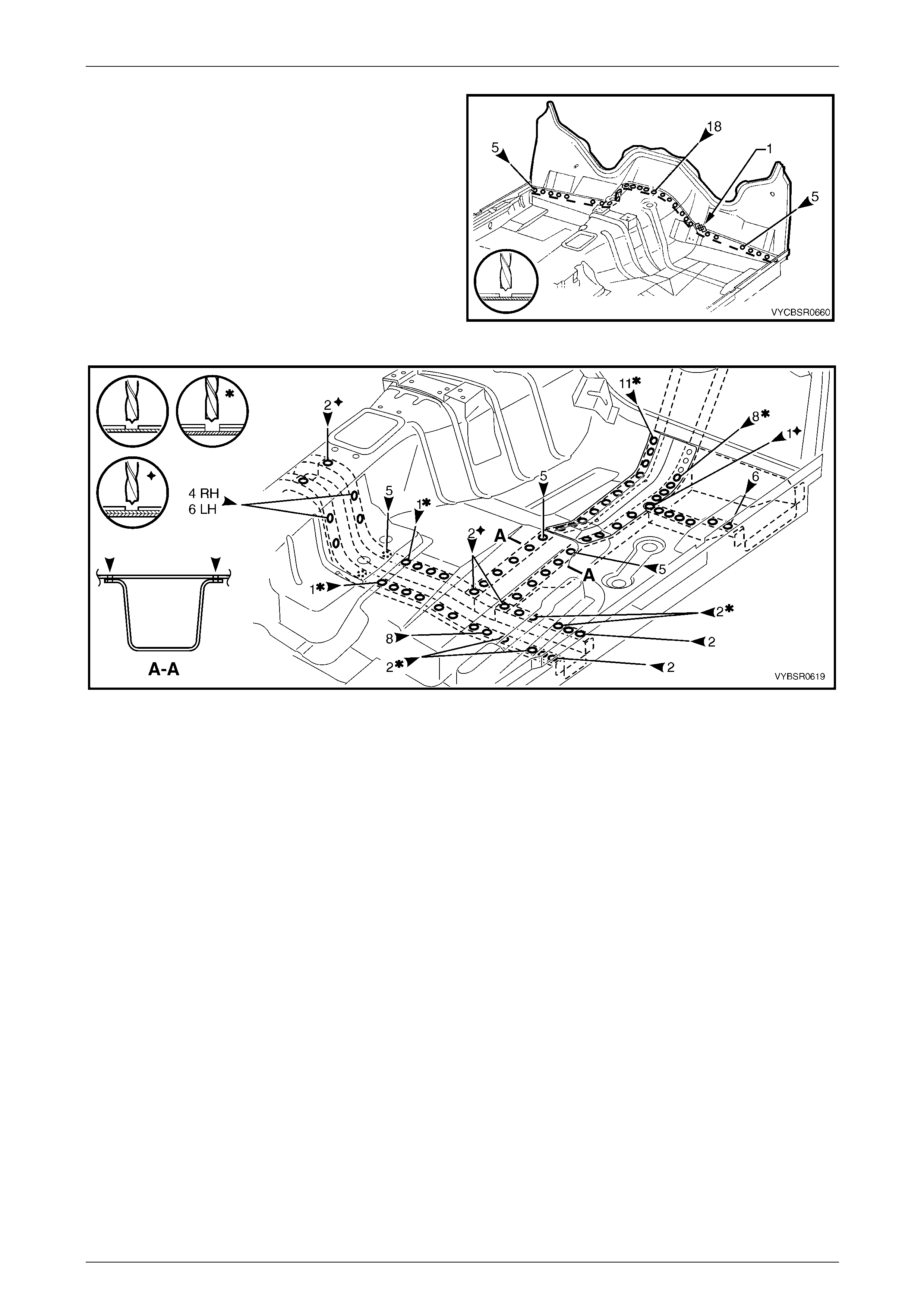
6 From underneath each side of the vehicle, spot cut the welds attaching the front floor pa nel assembly to the inner
rocker panel assembly. From inside (A), also spot cut five welds, refer to Figure 6E – 35.
Figure 6E – 35
6E Cabin Floor – Regular Cab Page 6E–20
Page 6E–20
7 Grind the MIG weld (1) attaching the front floor panel
extension to the front floor panel assembly.
8 Spot cut the welds attaching the front floor panel
extension to the front floor panel assembly.
9 Spot cut the welds attaching the front floor panel
assembly to the front side rail assemblies, each side of
the vehicle, refer to Figure 6E – 37.
Figure 6E – 36
Figure 6E – 37
10 Spot cut the welds attaching the front floor panel rear extension to the front floor panel assembly,
refer to Figure 6E – 38.
6E Cabin Floor – Regular Cab Page 6E–21
Page 6E–21
Figure 6E – 38
11 Remove the front floor assembly from the vehicle and repair any damage to adjacent panels as required.
12 Check and rectify the alignme nt of the body as required, refer to Section 3 E Body Construction – Regular Cab .
Replace
NOTE
Spot welding is the preferred method for
attaching of panels and should be used whenever
possible. Where the spot welding equipment
available will not access the required weld
position, a plug weld should be performed.
The same number and position of spot welds (or
plug welds) should be used when replacing the
panel, as was used during manufacture, in order
to maintain the original structural strength of the
vehicle.
1 As required, mark the new panel with drilling locations in preparation for plug welding. Drill holes as required.
2 Prepare all mating surfaces and treat with Weld Through Primer (Item 1) as requir ed,
refer to Section 3E Body Construction – Regular Cab .
3 Apply Acrylic Spot Weld Sealer (Item 2), refer to Section 3E Body Construction – Regular Cab .
4 Secure the front floor panel assembly in position and mak e severa l tack welds around its circumference.
5 Spot or plug weld the front floor panel assembly to the front floor panel rear extensio n and the inner rocker panel
assembly, refer to Figure 6E – 39.
6E Cabin Floor – Regular Cab Page 6E–22
Page 6E–22
Figure 6E – 39
6 On each side of the vehicle, spot or plug weld the front floor panel assembly to the front side rail assemblies,
refer to Figure 6E – 40.
Figure 6E – 40

6E Cabin Floor – Regular Cab Page 6E–23
Page 6E–23
7 Spot or plug weld the front floor panel extension to the
front floor panel assembly.
8 MIG weld (1) the front floor panel extension to the front
floor panel assembly.
9 From underneath each side of the vehicle, spot or plug
weld the front floor panel assembly to the inner rocker
panel assembly. From inside (A), also spot o r plug
weld, five places, refer to Figure 6E – 42.
Figure 6E – 41
Figure 6E – 42
10 Replace any other remov ed panels as required, refer to the relevant Section in this Supplement.
11 Refinish and paint panels and other components as required. Refer to Section 3 Body Construction.
12 Apply Joint Sealer (Item 3) as required, refer to Section 3E Body Construction – Re gular Cab .
13 Apply Cavity Wax (Item 8) as required to the inside of any box secti ons or areas inaccessible to paint,
refer to Section 3E Body Construction – Regular Cab .
14 Apply floor deadeners as req uired, refer to Section 3E Body Construction – Regu lar Cab .
15 Apply Spray-On Deade ner (Item 7) as required to the underside of the flo or,
refer to Section 3E Body Construction – Regular Cab .
16 Reinstall the remaining bolt-on panels and components as required, refer to the appropriate Section of the MY2005
VZ Service Information.
6E Cabin Floor – Regular Cab Page 6E–24
Page 6E–24
2.7 Transmission Support Bracket, AWD –
Replace
Remove
1 Remove the adjacent bolt-on panels and components as described in the appropriate section of the MY2005 VZ
Service Information.
2 Using a scraper and heat gun, remove the body sealer and deadener from the front floor attaching areas.
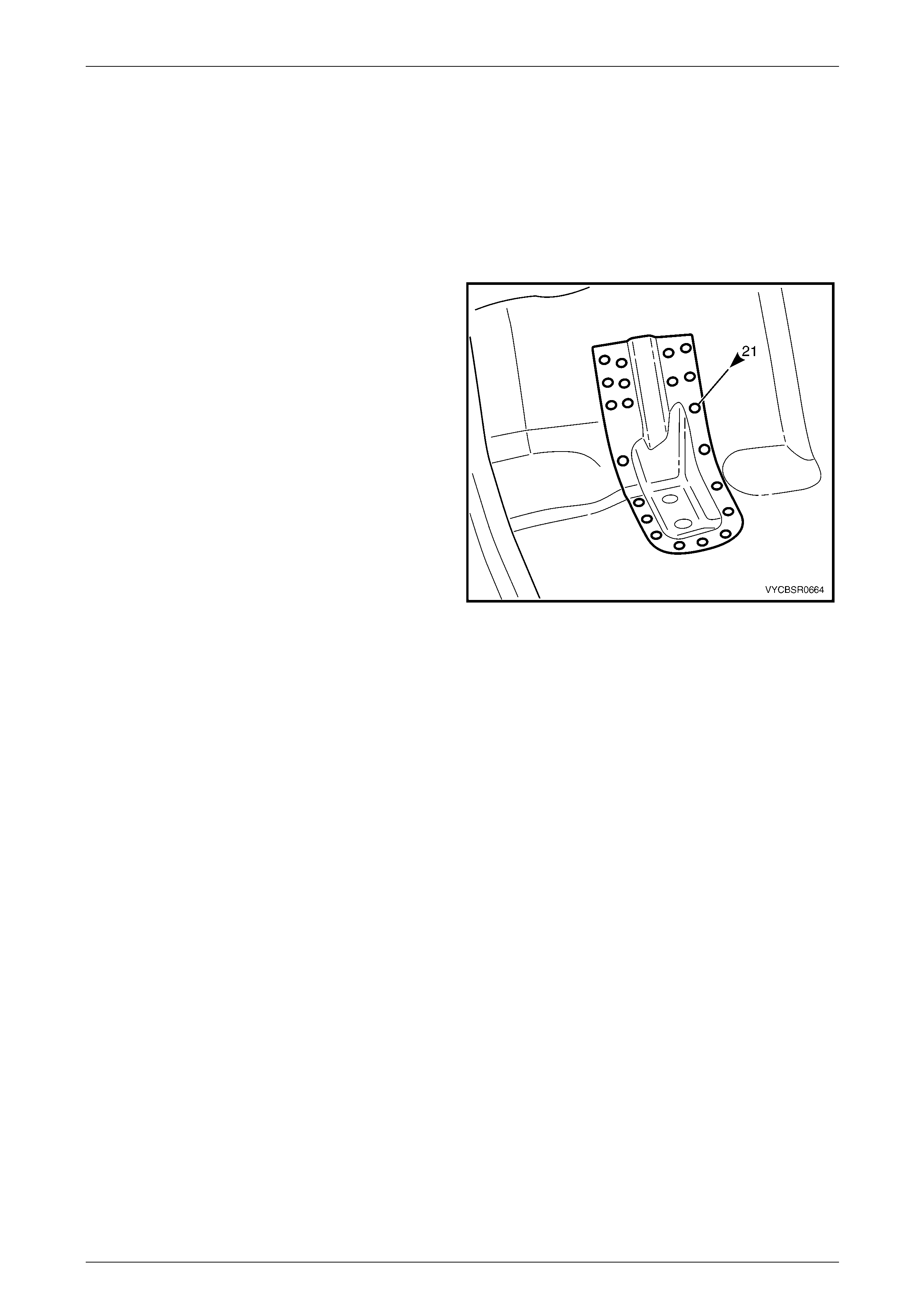
3 Spot cut the welds attaching the transmission support
bracket to the vehicle.
4 Remove the transmission support bracket from the
vehicle and repair any damag e to the adjacent area as
required.
Figure 6F – 43
6E Cabin Floor – Regular Cab Page 6E–25
Page 6E–25
Replace
NOTE
Spot welding is the preferred method for
attaching of panels and should be used whenever
possible. Where the spot welding equipment
available will not access the required weld
position, a plug weld should be performed.
The same number and position of spot welds (or
plug welds) should be used when replacing the
panel, as was used during manufacture, in order
to maintain the original structural strength of the
vehicle.
1 As required, mark the new panel with drilling locations in preparation for plug welding. Drill holes as required.
2 Prepare all mating surfaces and treat with Weld Through Primer (Item 1) as required,
refer to Section 3E Body Construction – Regular Cab .
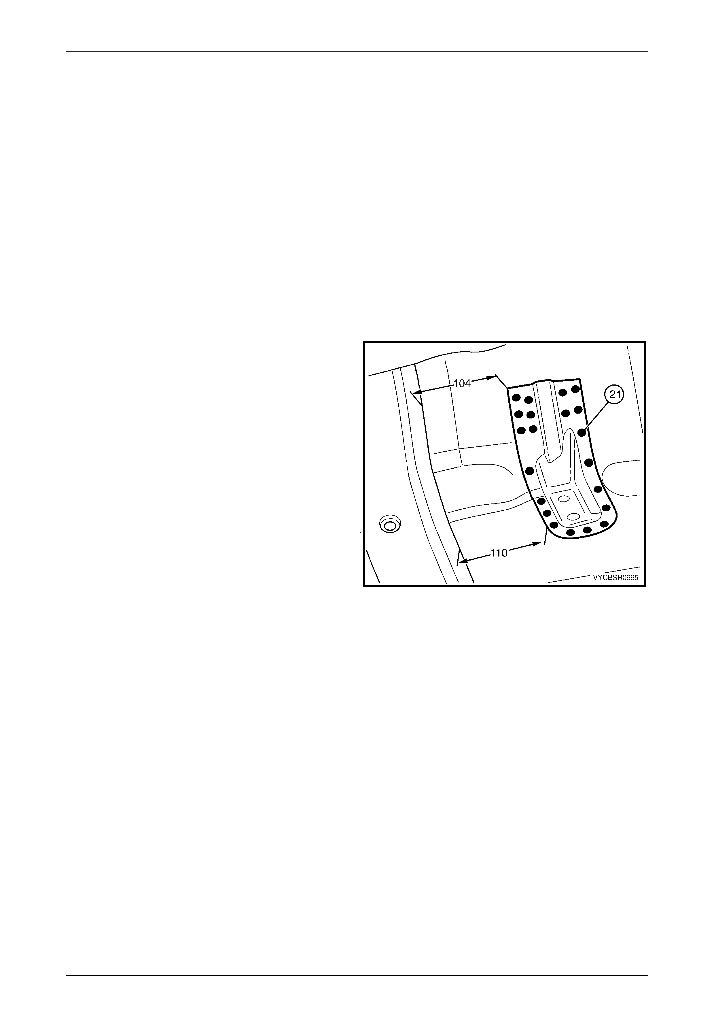
3 Position the transmission support bracket to the
dimensions shown, measuring from the front edge of
the crossmember flange.
NOTE
Positioning of the transmission support bracket is
critical to driveline orientati on.
4 Temporarily bolt the transmission crossmember in
position to help locate the mount.
5 Spot or plug weld the transmission supp ort bracket to
the front floor panel assembly.
6 Refinish and paint panels and other components as
required. Refer to Section 3 Body Construction .
7 Apply Cavity Wax (Item 8) as required to the inside of
any box sections or areas inaccessible to paint,
refer to Section 3E Body Construction – Regular Cab .Figu re 6F – 44
8 Apply floor deadeners as req uired, refer to Section 3E Body Construction – Regu lar Cab .
9 Apply Spray-On Deadener (Item 7) as required to the underside of the floor,
refer to Section 3E Body Construction – Regular Cab .
10 Reinstall the remaining bolt-on panels and components as required, refer to the appropriate Section of the MY2005
VZ Service Information.