7A Body Side – Sedan Page 7A-1
Page 7A-1
Section 7A
Body Side – Sedan
ATTENTION
Before performing any service operation or other procedure described in this Section, refer to Section 2
Precautions in this Supplement and Section 00 Warnings, Cautions and Notes in the MY2005 VZ Service
Information for correct workshop practices with regard to safety and/or property damage.
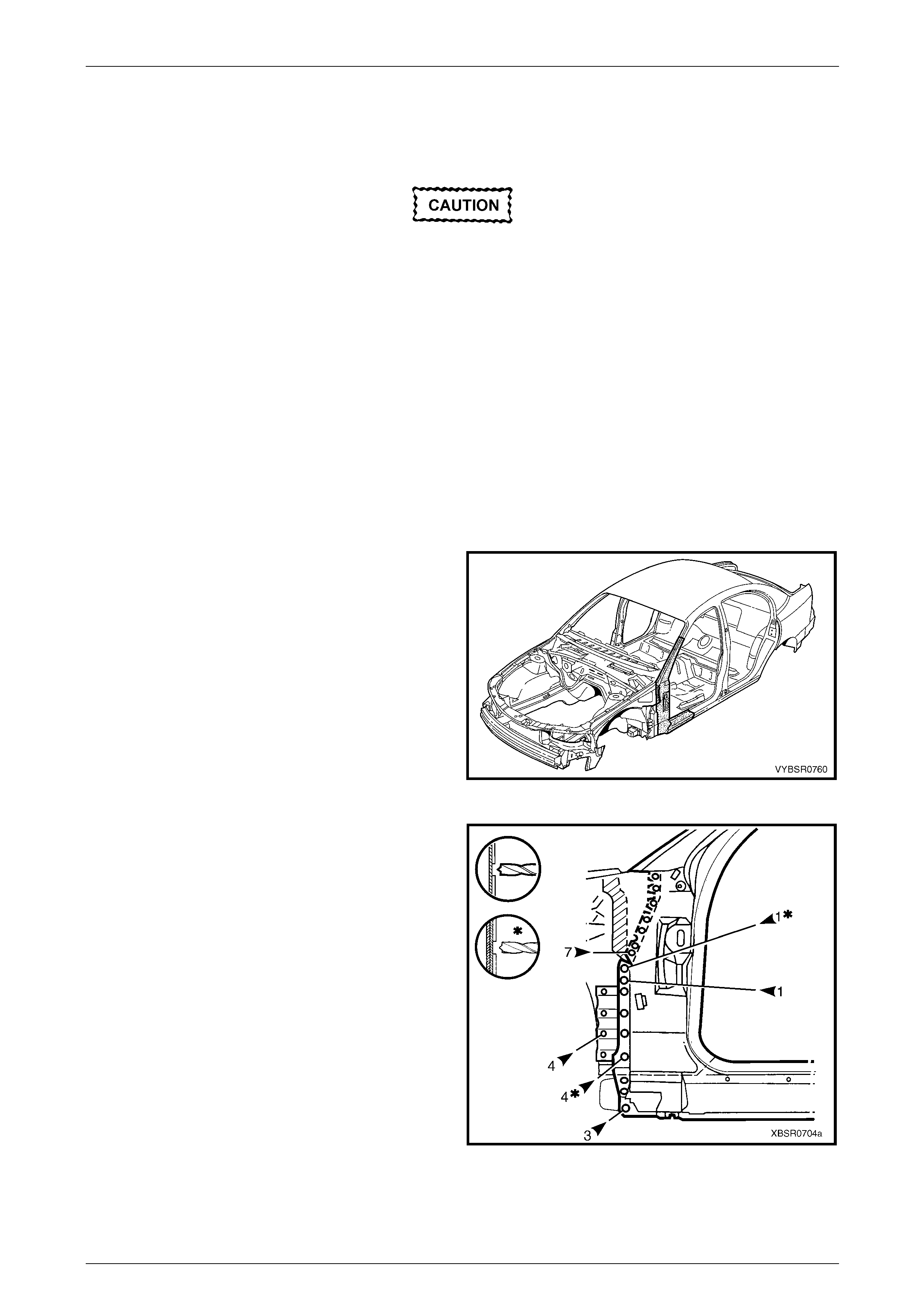
The structure of the body shell has been
developed using complex design and
development techniques. In addition to
meeting all required standards, the vehicle
body is also a critical part of the overall safety
systems. It is therefore imperative the repair
procedures described here are adhered to
during all vehicle body repairs.
1 General Description ...............................................................................................................................3
1.1 Body Side Components ........................................................................................................................................ 3
2 Service Operations.................................................................................................................................5
2.1 Rear Quarter Panel – Replace............................................................................................................................... 5
Remove................................................................................................................................................................... 5
Replace................................................................................................................................................................... 8
2.2 Tail Lamp Housing, Quarter Panel Lower Extension and Quarter Panel Upper Extension – Replace.........11
Remove................................................................................................................................................................. 11
Replace................................................................................................................................................................. 13
2.3 Tail Lamp Housing Brace – Replace.................................................................................................................. 15
Remove................................................................................................................................................................. 15
Replace................................................................................................................................................................. 16
2.4 Door Opening Frame Assembly – Replace........................................................................................................ 17
Remove................................................................................................................................................................. 17
Replace................................................................................................................................................................. 22
2.5 Door Opening Frame Assembly – Partial Replace, Hinge Pillar...................................................................... 27
Remove................................................................................................................................................................. 27
Replace................................................................................................................................................................. 30
2.6 Door Opening Frame Assembly – Partial Replace. Centre Pillar..................................................................... 36
Remove................................................................................................................................................................. 36
Replace................................................................................................................................................................. 39
2.7 Door Opening Frame Assembly – Partial Replace, Lock Pillar........................................................................ 43
Remove................................................................................................................................................................. 43
Replace................................................................................................................................................................. 46

7A Body Side – Sedan Page 7A-2
Page 7A-2
2.8 Door Opening Frame Assembly – Partial Replace, Rocker Panel................................................................... 49
Remove................................................................................................................................................................. 49
Replace................................................................................................................................................................. 52
2.9 Fender Lower Rear Bracket – Replace............................................................................................................... 57
2.10 Hinge Pillar Inner Panel Assembly – Replace ................................................................................................... 58
Remove................................................................................................................................................................. 58
Replace................................................................................................................................................................. 60
2.11 Quarter Panel Inner Assembly – Replace.......................................................................................................... 63
Remove................................................................................................................................................................. 63
Replace................................................................................................................................................................. 65
2.12 Quarter Panel Inner Assembly – Partial Replace.............................................................................................. 68
Remove................................................................................................................................................................. 68
Replace................................................................................................................................................................. 70
7A Body Side – Sedan Page 7A-3
Page 7A-3
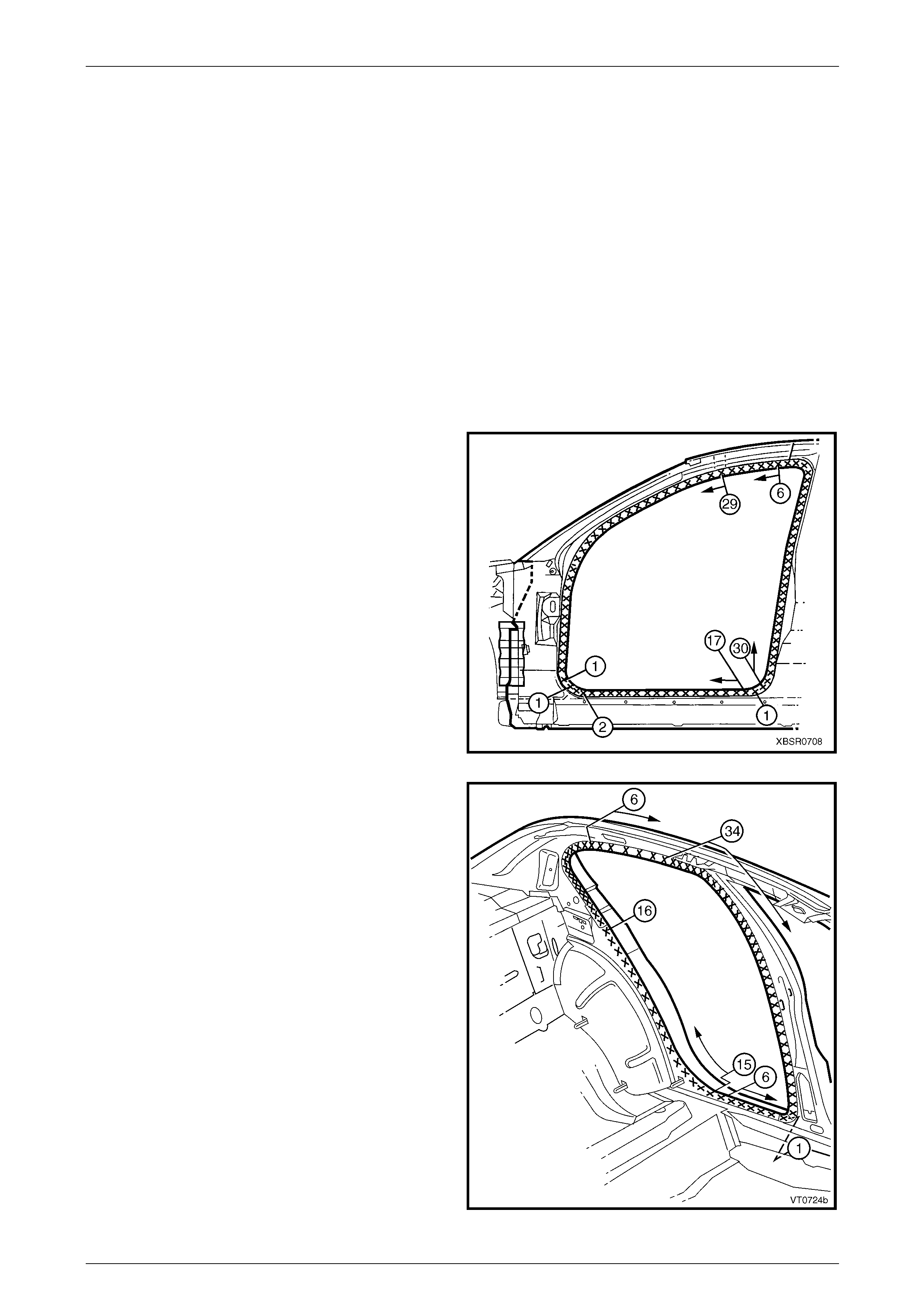
1 General Description
This Section describes the replacement procedures for the body side components of the Sedan body structure. Removal
of bolt-on panels and mechanic al components is not covered.
When repairing the body side of the vehicle, care must be taken to ensure the structure is returned to its original
production configuration. This is especially important to maintain side impact standards and for the veh icle’s occupant
protection system to operate correctly.
This Section includes door opening frame assembly partial r eplacement procedures for the hinge pillar, centre pillar, lock
pillar and rocker panel. These procedures must be followed carefull y, as they regularl y involve hidden reinforceme nt
panels. The cutting locations specified are the only plac es allowable.
NOTE
• A sunroof option is available that is fitted on
the production line. To cater for this option, a
stainless steel front drain tube is also fitted
within the hinge pillar cavity, therefore the
partial replacement procedure for the hinge
pillar must not be performed on these
vehicles.
• It is imperative the correct body adhesives,
sealers, deadeners and cavity waxes are
used when repairing th e body structure. Refer
to Section 3A Body Construction – Sedan.
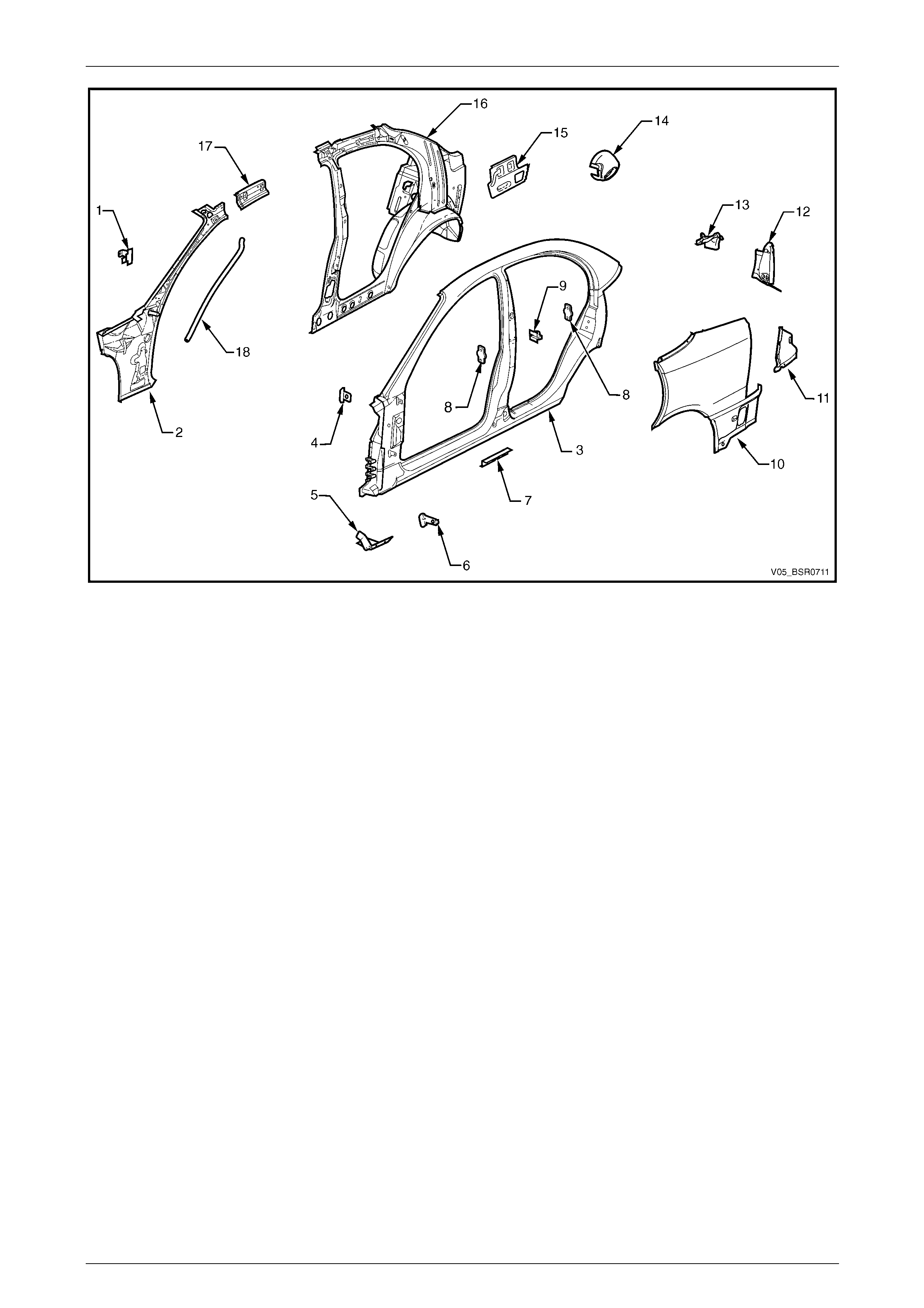
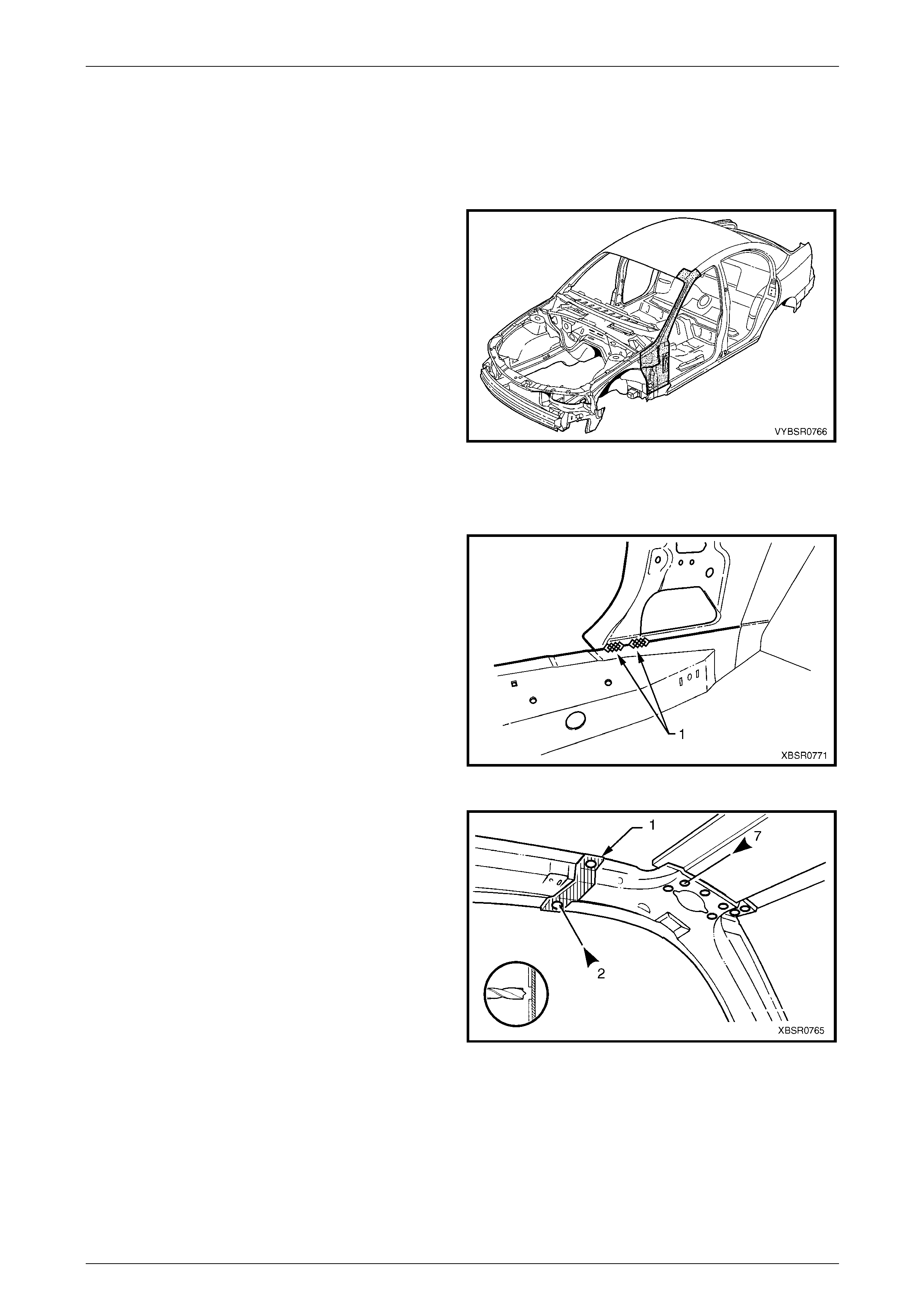
1.1 Body Side Components
The shaded components in Figure 7A – 1 are those dealt
with in this Section.
The components and assemblies shown in
Figure 7A – 2 are the serviceabl e parts that form
the basis of the repair procedures in this Secti on.
For a detailed view of the body components,
refer to Section 3A Body Construction – Sedan .
NOTE
Always refer to an Authorised Retailer for spare
parts availability configurations.
Cavity foam may be used within the hinge,
centre and lock pillars. Care needs to be
taken when repairing the vehicle in these
areas, refer to Section 2 Precautions prior to
beginning any work for further information
regarding the use of cavity foam.
Figure 7A – 1
7A Body Side – Sedan Page 7A-4
Page 7A-4
Figure 7A – 2
Legend
1 Hinge Pillar Trim Panel Bracket, Left-hand / Right-hand
2 Hinge Pillar Inner Panel Assembly, Left-hand / Right-hand
3 Door Opening Frame Assembly, Left-hand / Right-hand
4 Fender Upper Rear Bracket, Left-hand / Right-hand
5 Fender Lower Rear Bracket, Left-hand / Right-hand
6 Fender Rear Bracket, Left-hand / Right-hand
7 Underbody Jacking Locator, Left-hand / Right-hand
8 Front or Rear Door Striker Anchor Plate, Left-hand / Right-
hand
9 Rear Door Check Link Bracket, Left-hand / Right-hand
10 Rear Quarter Panel, Left-hand / Right-hand
11 Quarter Panel Lower Extension, Left-hand / Right-hand
12 Tail Lamp Housing, Left-hand / Right-hand
13 Quarter Panel Upper Extension, Left-hand / Right-hand
14 Fuel Filler Pipe Housing, Right-hand
15 Tail Lamp Housing Brace, Left-hand / Right-hand
16 Quarter Panel Inner Assembly, Left-hand / Right-hand
17 Quarter Panel Inner Extension, Left-hand / Right-hand
18 Sunroof Front Drain Tube, Left-hand / Right-hand
NOTE
• Door opening frame assembly (4) includes
parts No. 4, 5, 6, 7, 8, 9 and 18.
• Quarter panel inner assembly (16) includes
parts 17 and the rear wheelhouse inn er panel
assembly which is also available separately,
refer to Section 10A Body Rear – Sedan.
7A Body Side – Sedan Page 7A-5
Page 7A-5
2 Service Operations
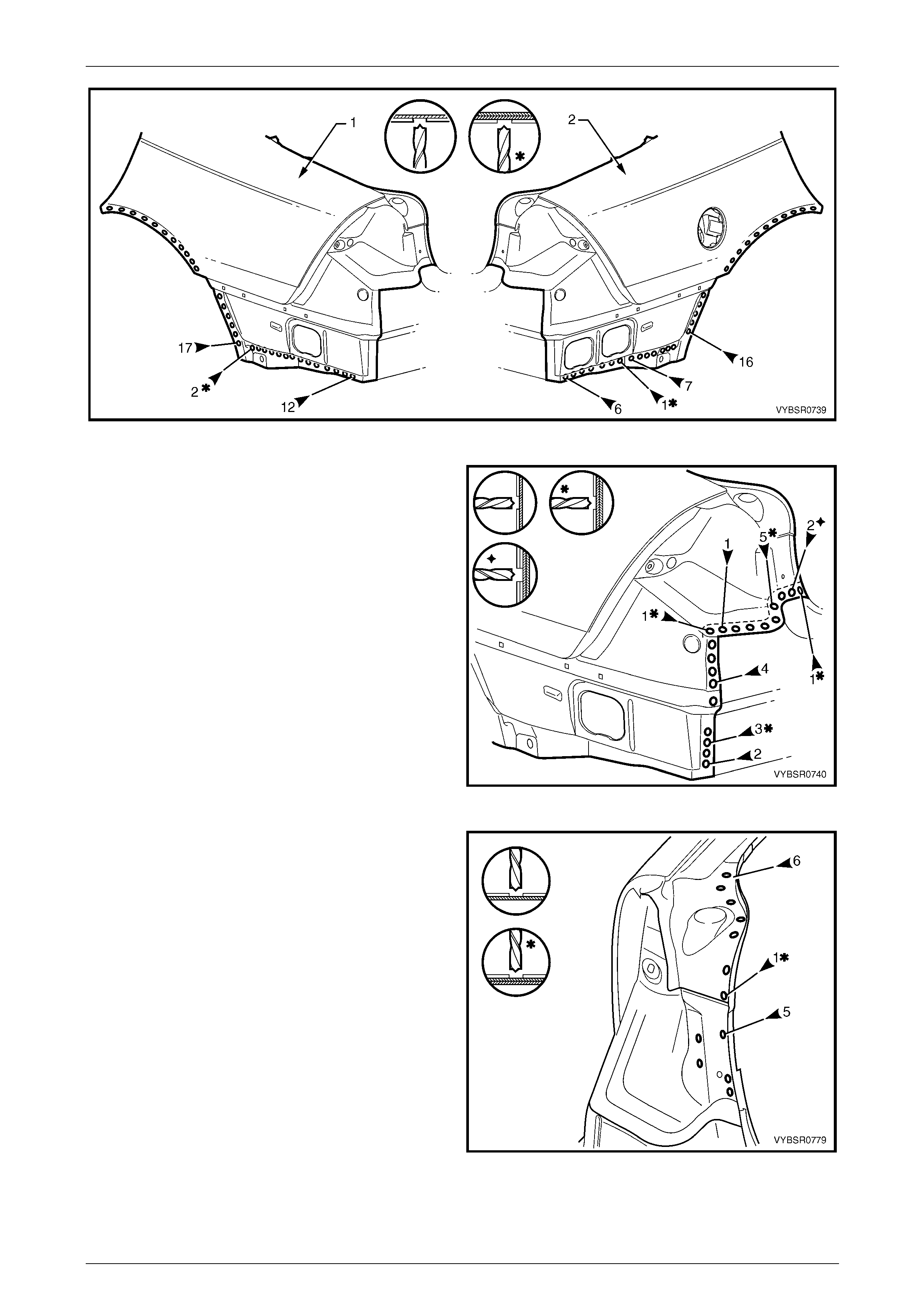
2.1 Rear Quarter Panel – Replace
To avoid the possibility of fire, take particular
care when cuttin g or w elding at the r ear of th e
vehicle. Remove the fuel tank and plug the
fuel lines.
NOTE
This procedure details the removal of the rear
quarter panel as an assembly with the tail lamp
housing, quarter panel upper extension, quarter
panel lower extension and fuel filler pipe housing
(for right-hand side). Ho wever these parts are not
available as an assembly and must be ordered
separately.
Remove
1 Remove the adjacent bolt-on panels a nd components
as described in the appropriate Section of th e MY
2005 VZ Service Information.
2 Remove the rear window, refer to Section 1A6
Stationary Windows in the MY 2005 VZ Service
Information.
3 Remove the rear bumper impact bar,
refer to Section 3 Body Construction.
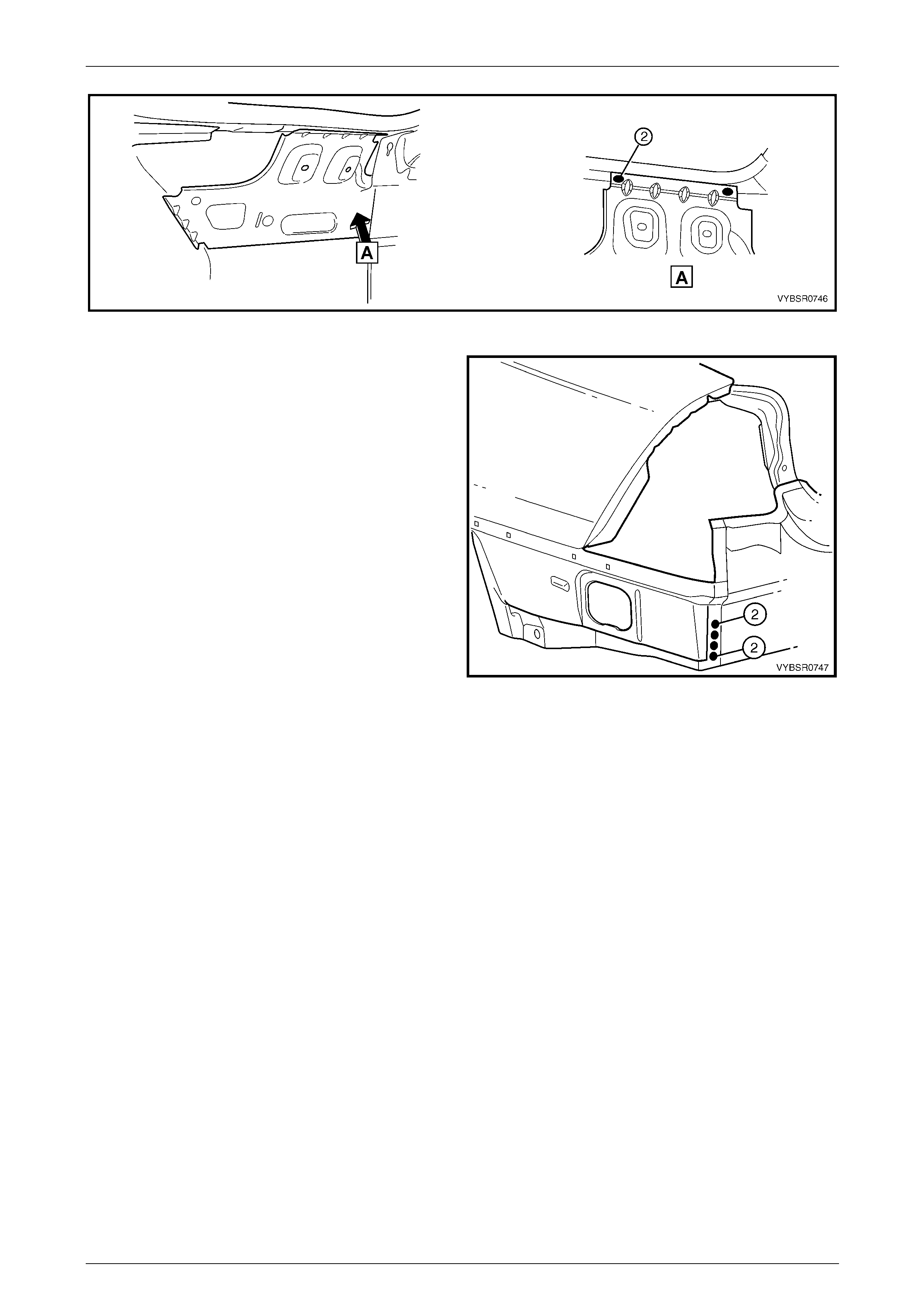
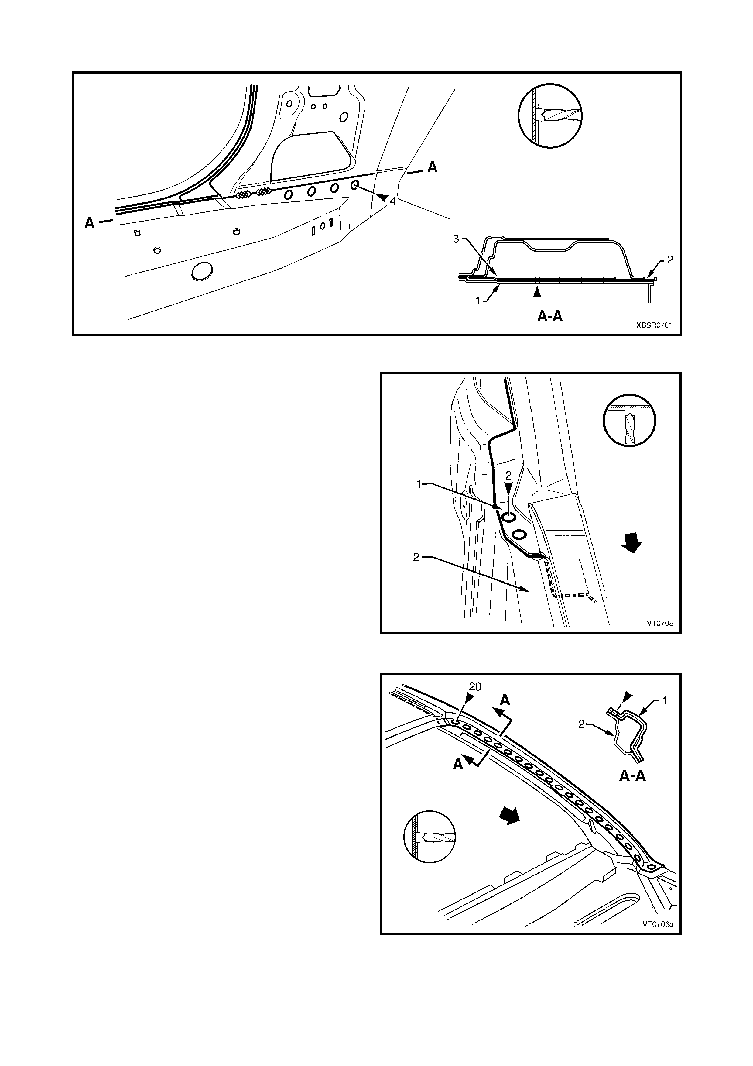
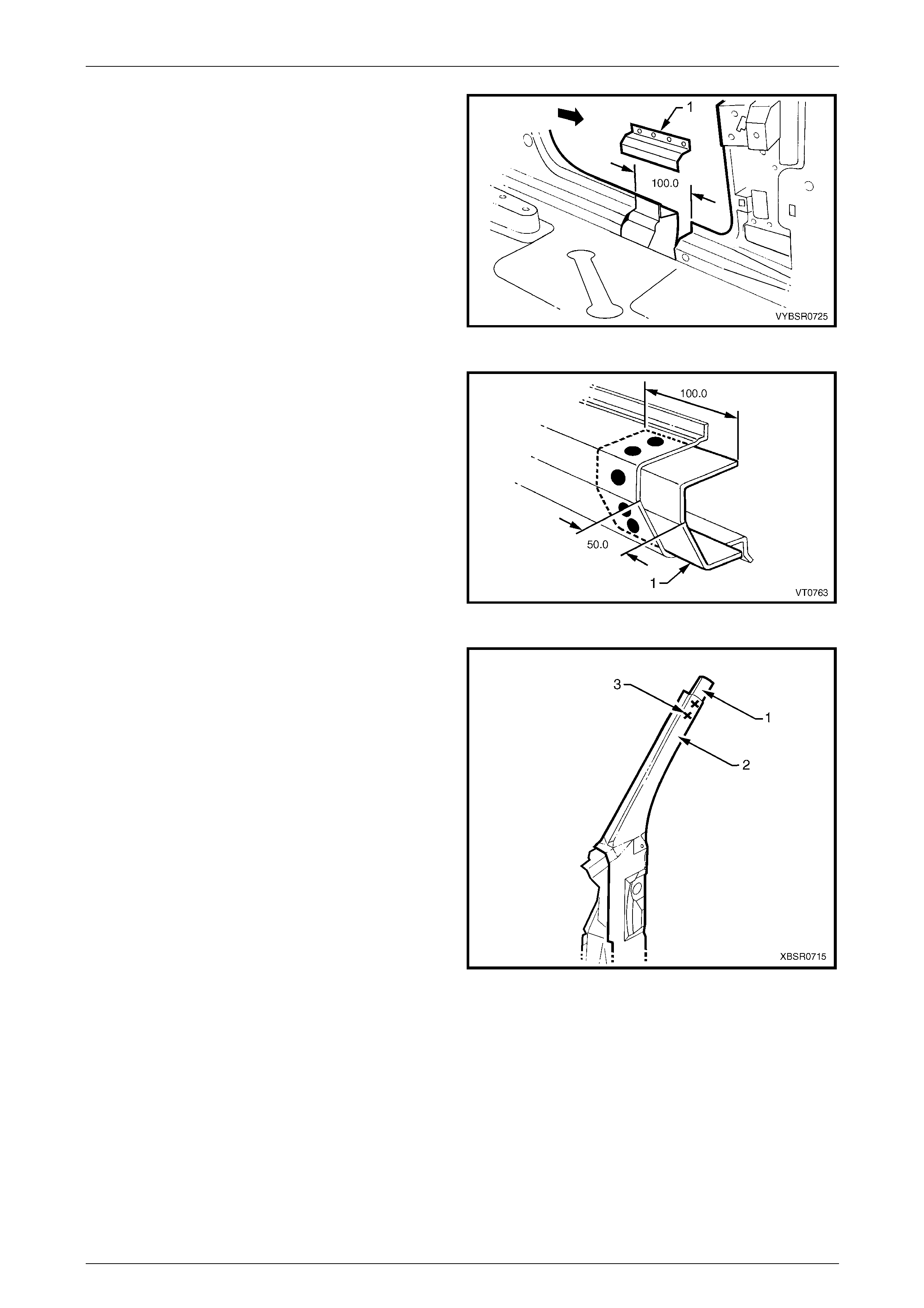
Figure 7A – 3
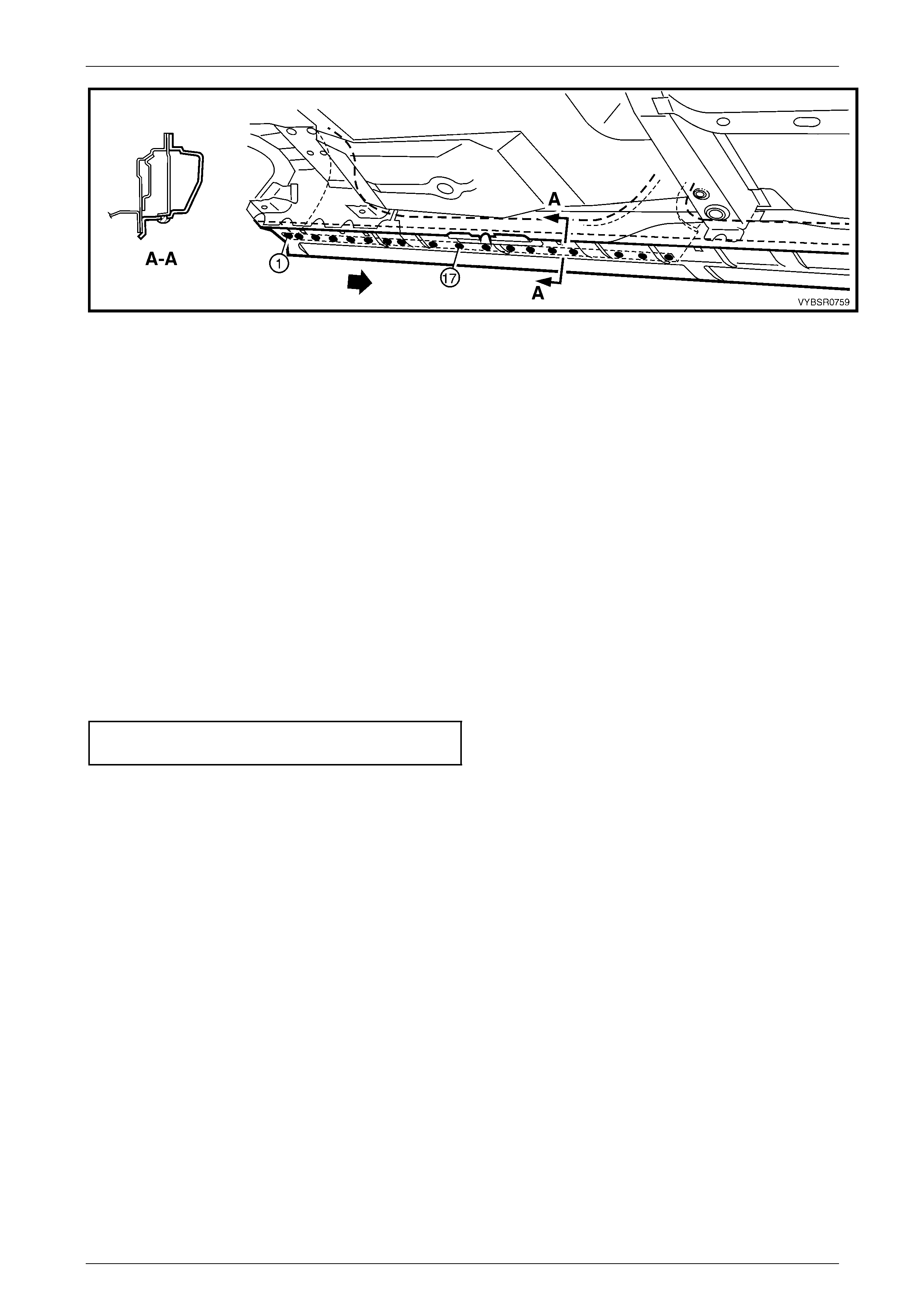
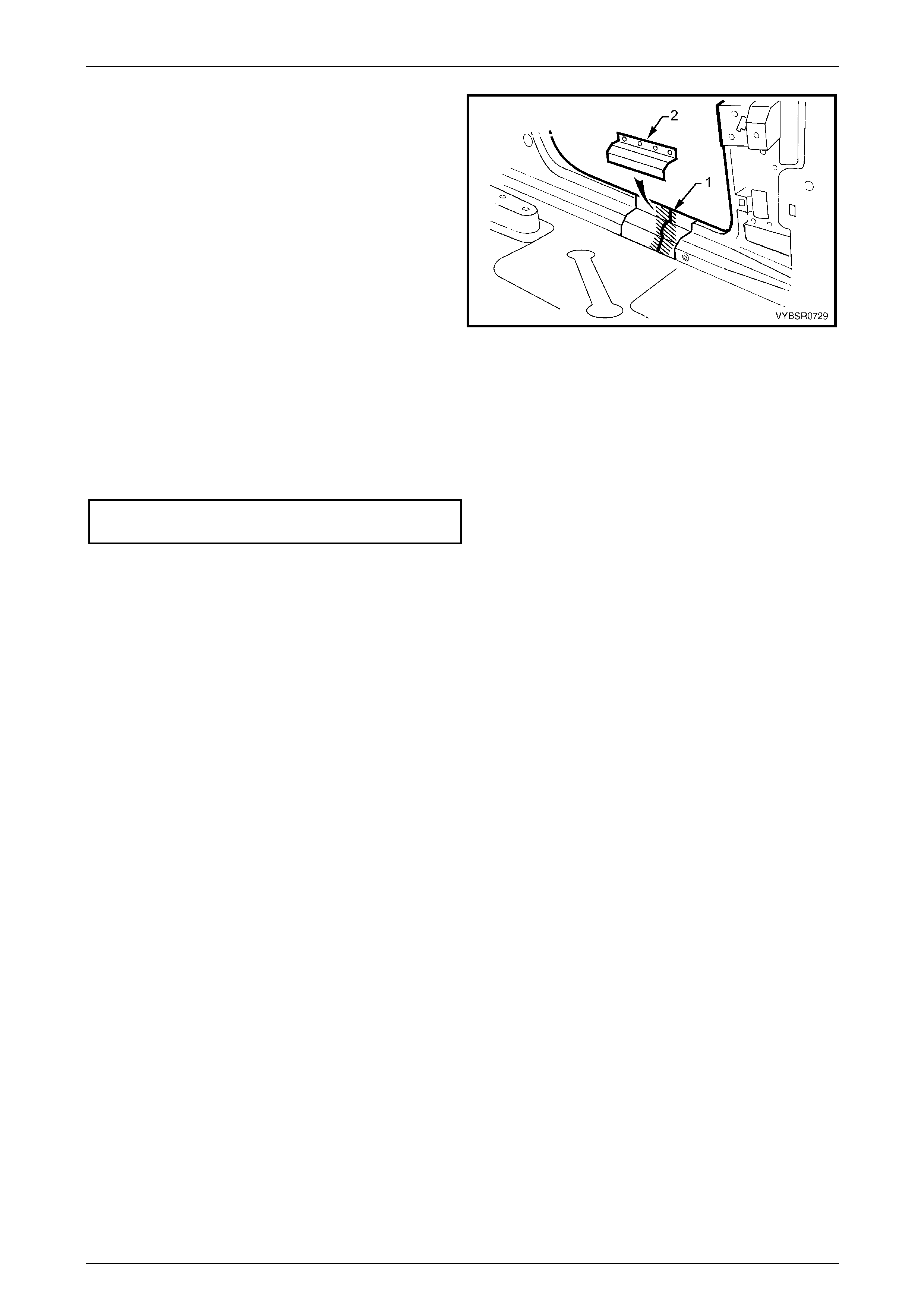
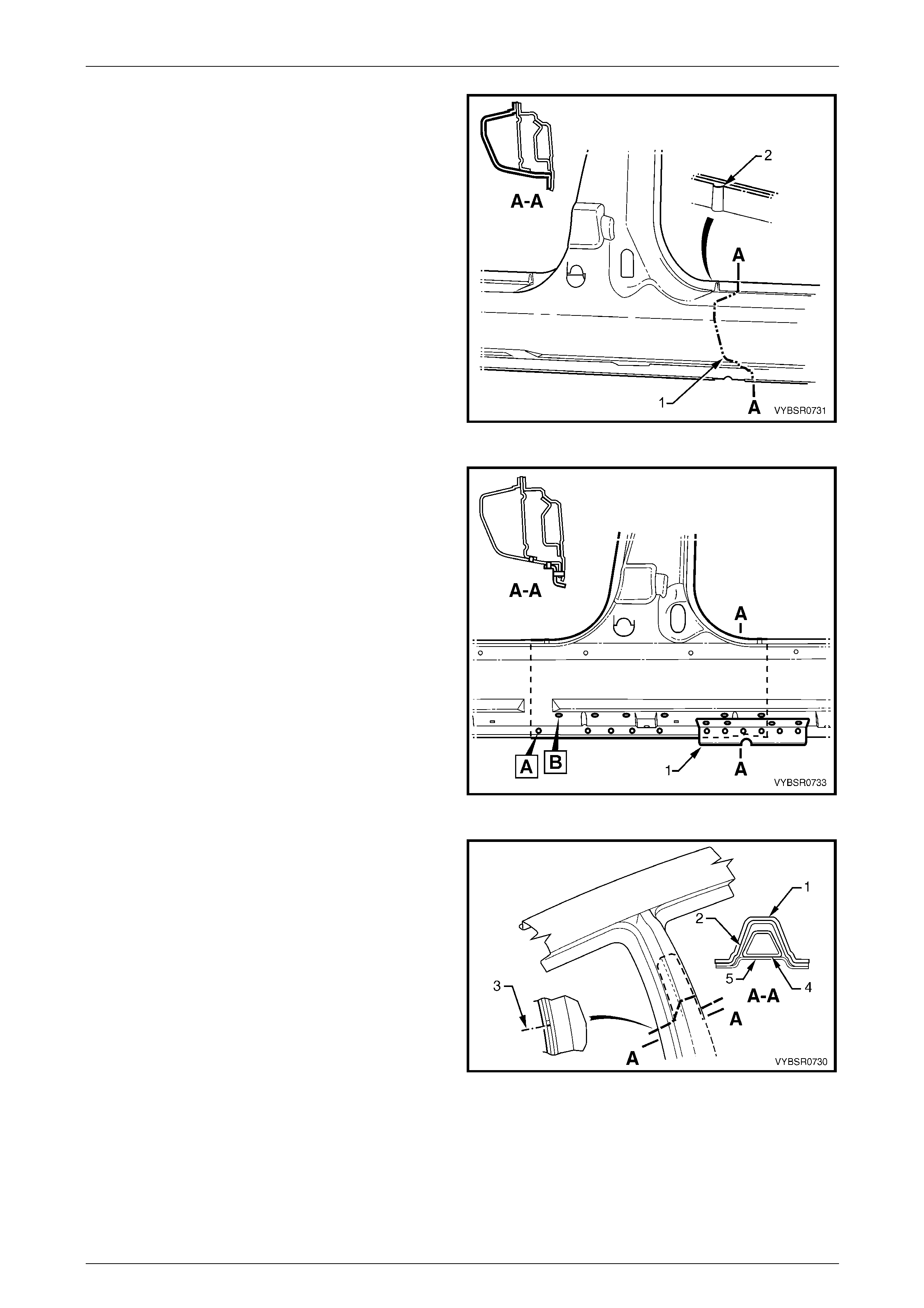
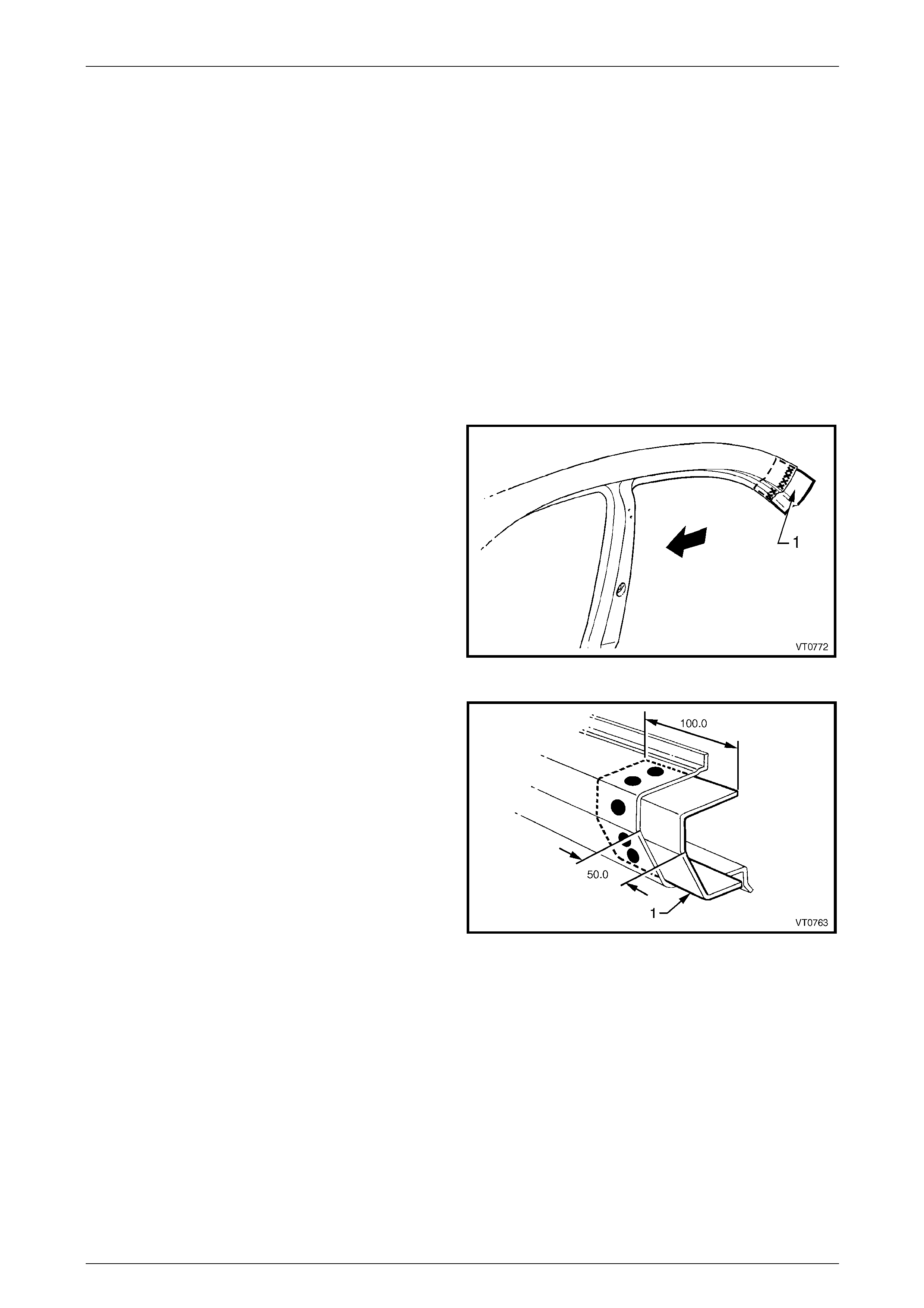
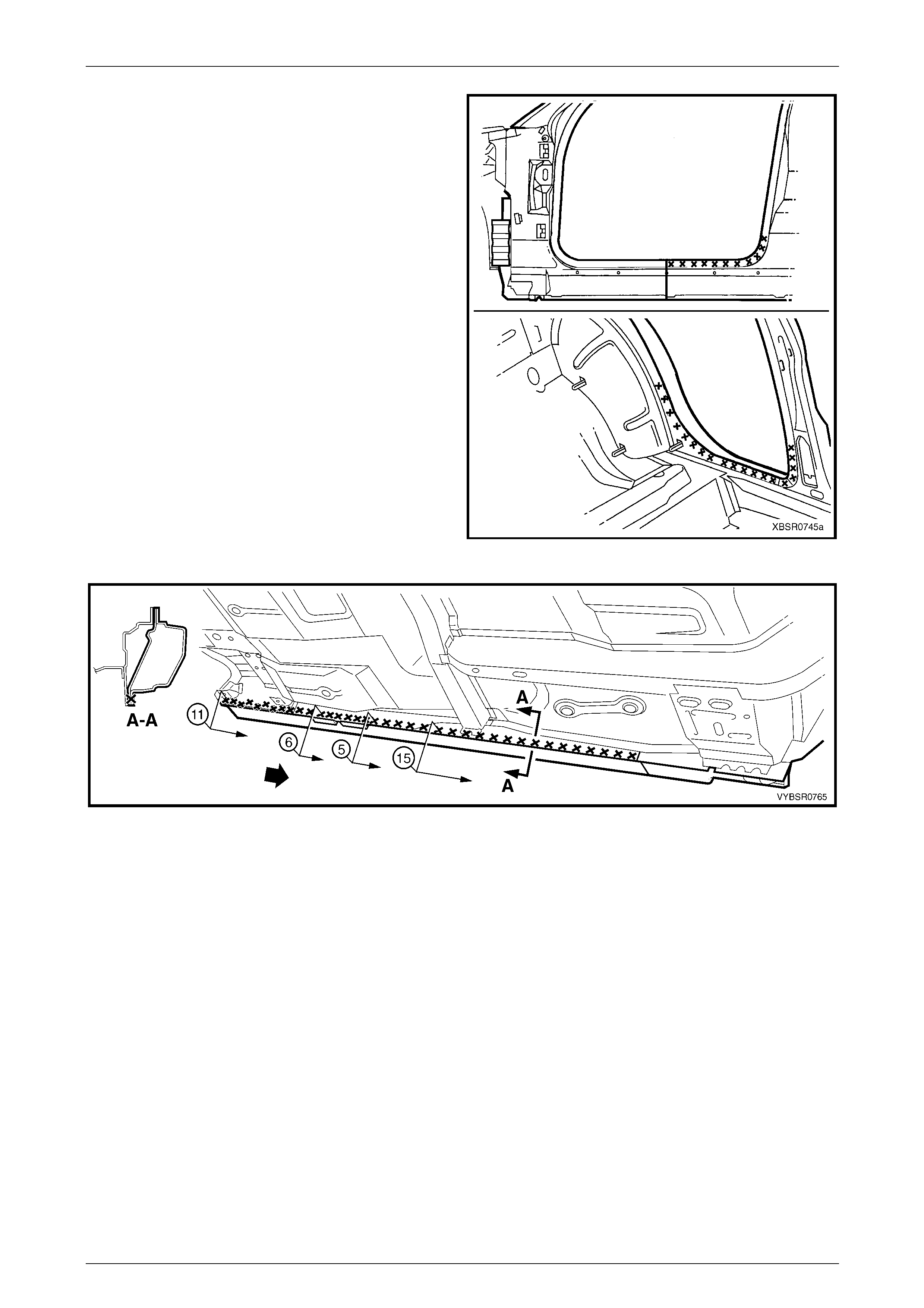
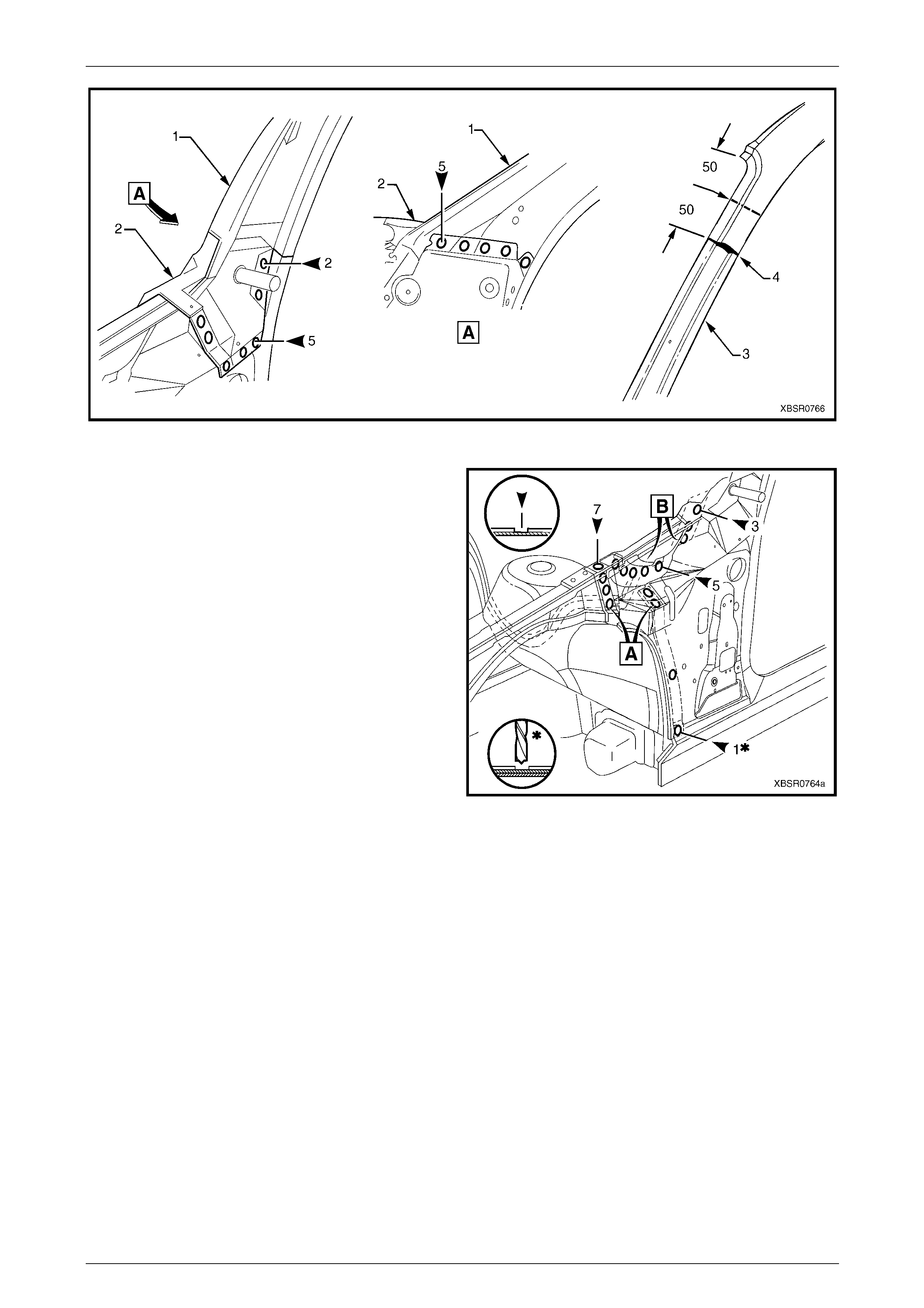
4 Spot cut the welds attaching the rear quarter panel to
the door opening frame assembly.
5 Spot cut the welds attaching the rear quarter panel to
the quarter panel inner assembly and rear
compartment floor panel outer exte nsion. There are a
different number of welds on the left-hand panel (1) to
the right-hand panel (2), refer to Figure 7A – 5.
Figure 7A – 4
7A Body Side – Sedan Page 7A-6
Page 7A-6
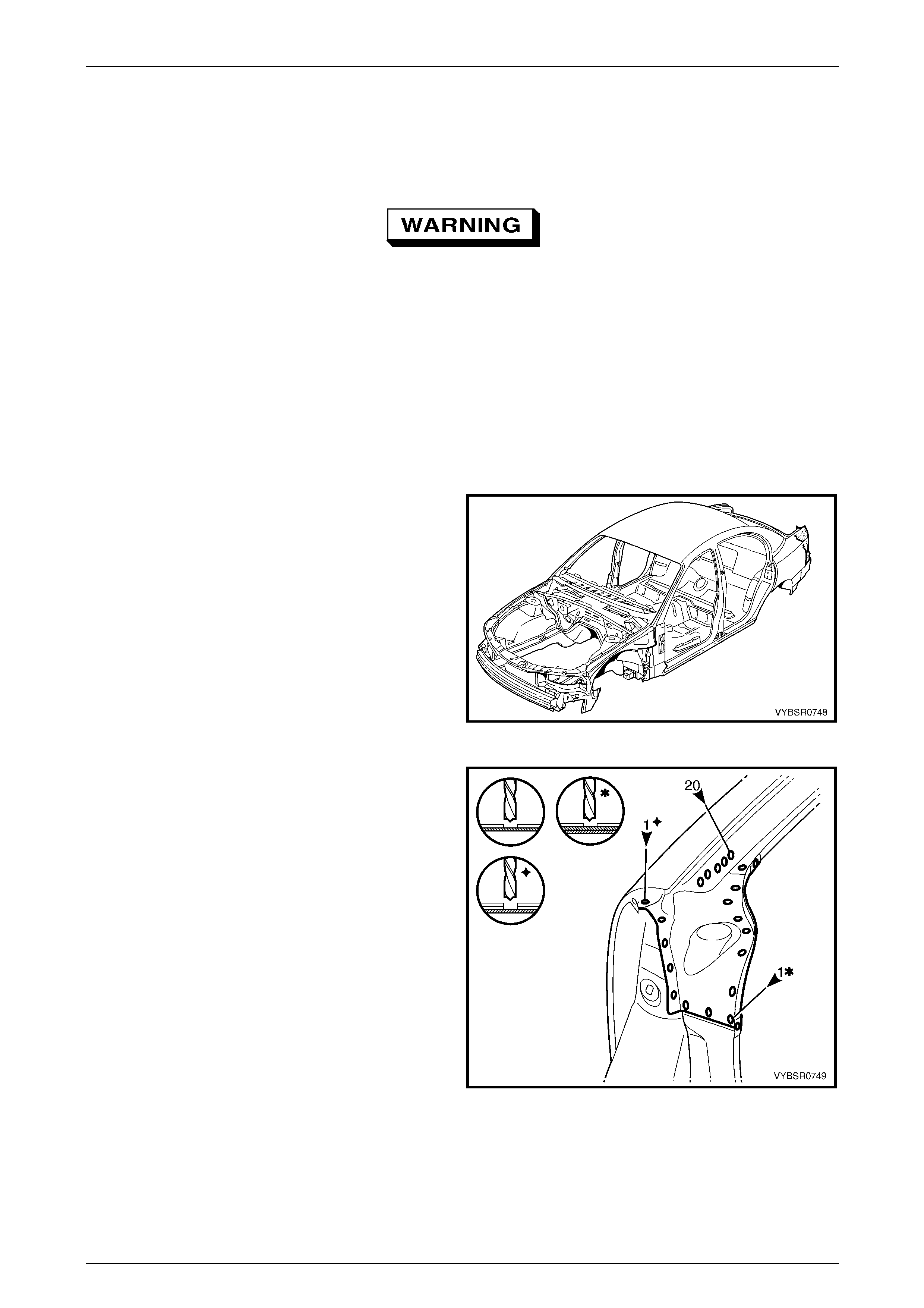
Figure 7A – 5
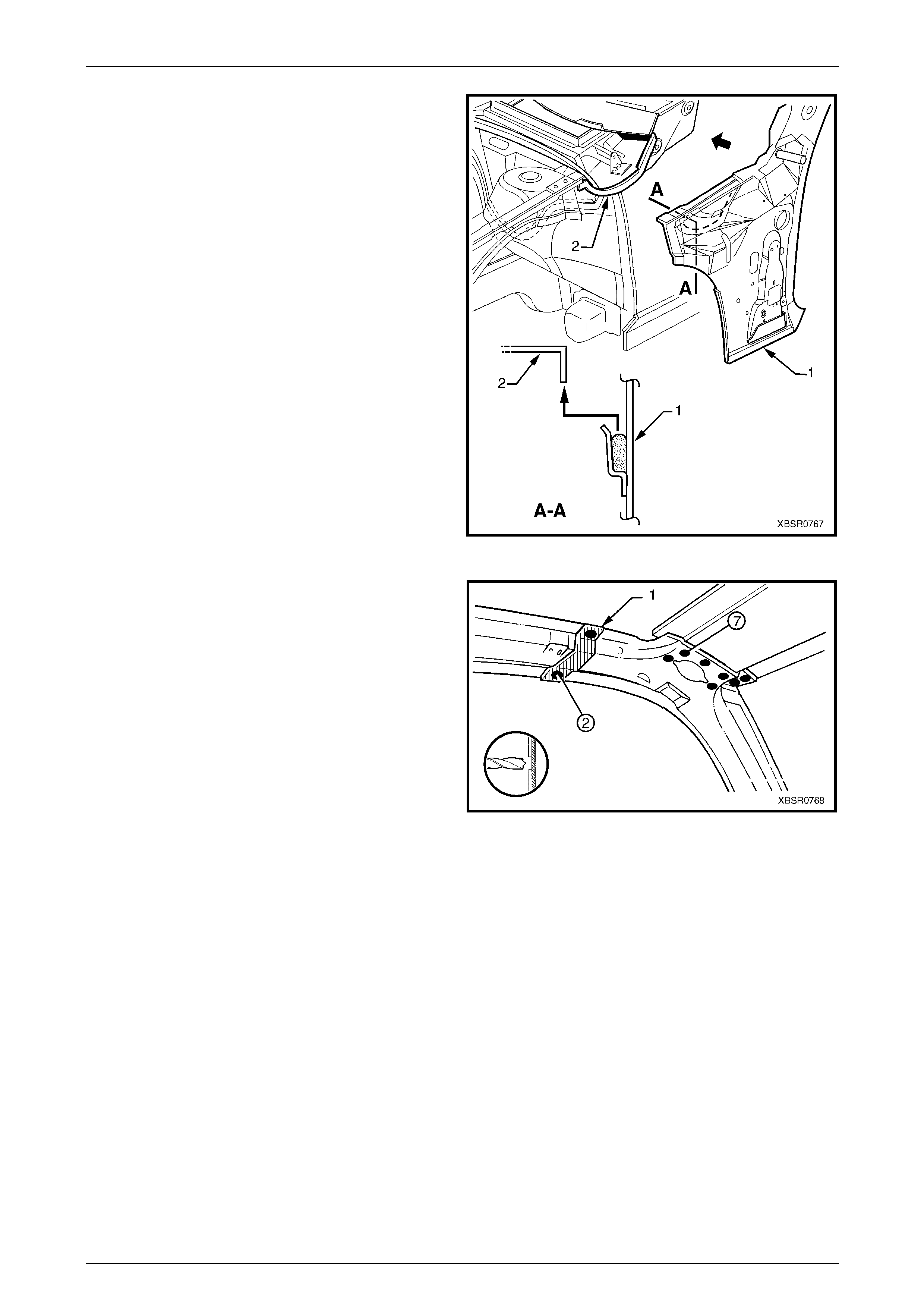
6 Spot cut the rear quarter panel from the rear end lower
panel and web plate.
7 Spot cut the tail lamp housing and q uarter panel lower
extension panel from the rear end lower panel.
NOTE
If the tail lamp housing and quarter panel lower
extension are to remain, modify this procedure
accordingly.
Figure 7A – 6
8 Spot cut the rear quarter panel upper extension and
tail lamp housing from the rear end lower panel
extension.
NOTE
If the tail lamp housing and quarter panel lower
extension and quarter pa nel upper extension are
to remain, this step is not required. Also refer to
2.2 Tail Lamp Housing, Quarter Panel Lower
Extension and Quarter Panel Upper Extension –
Replace
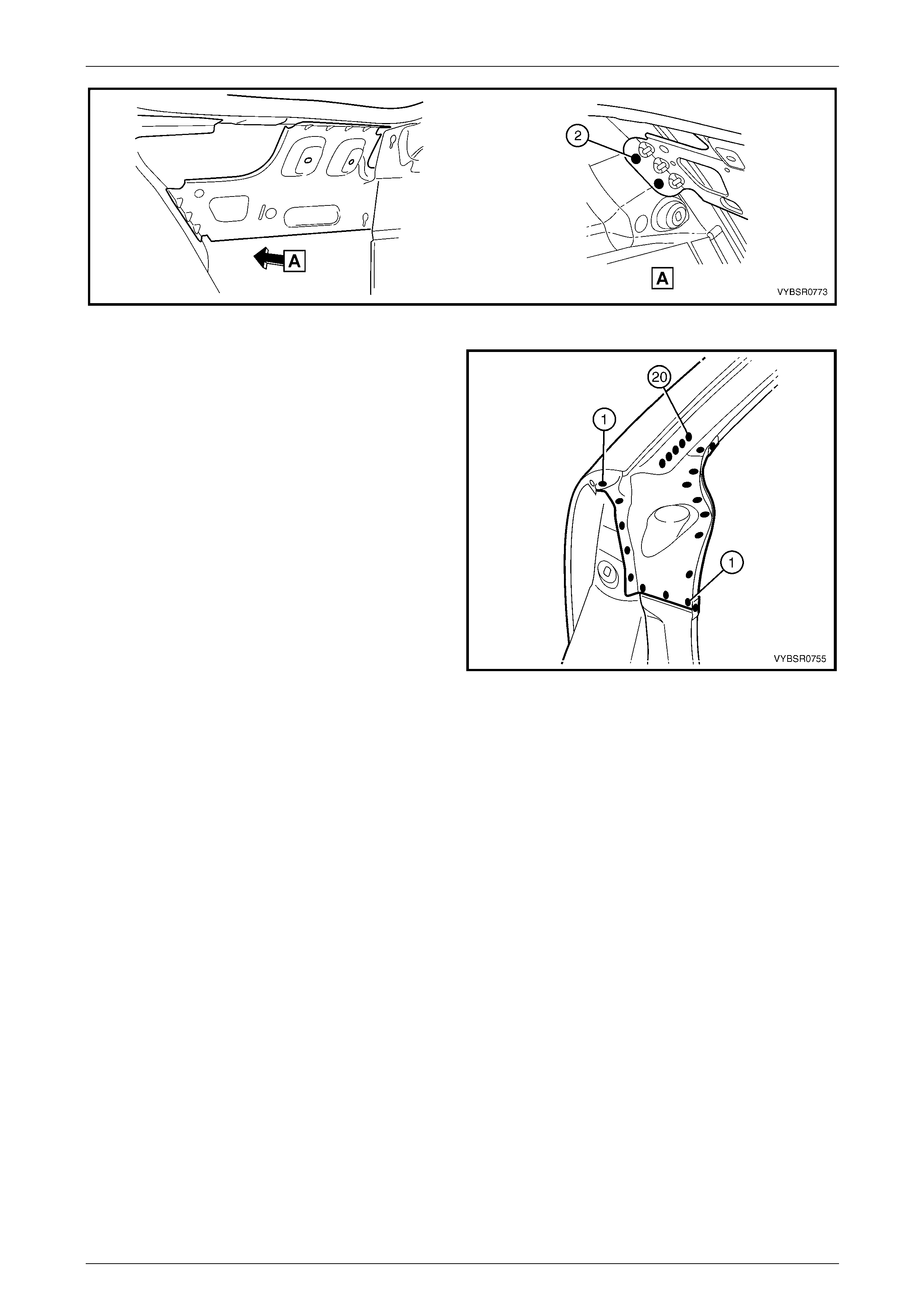
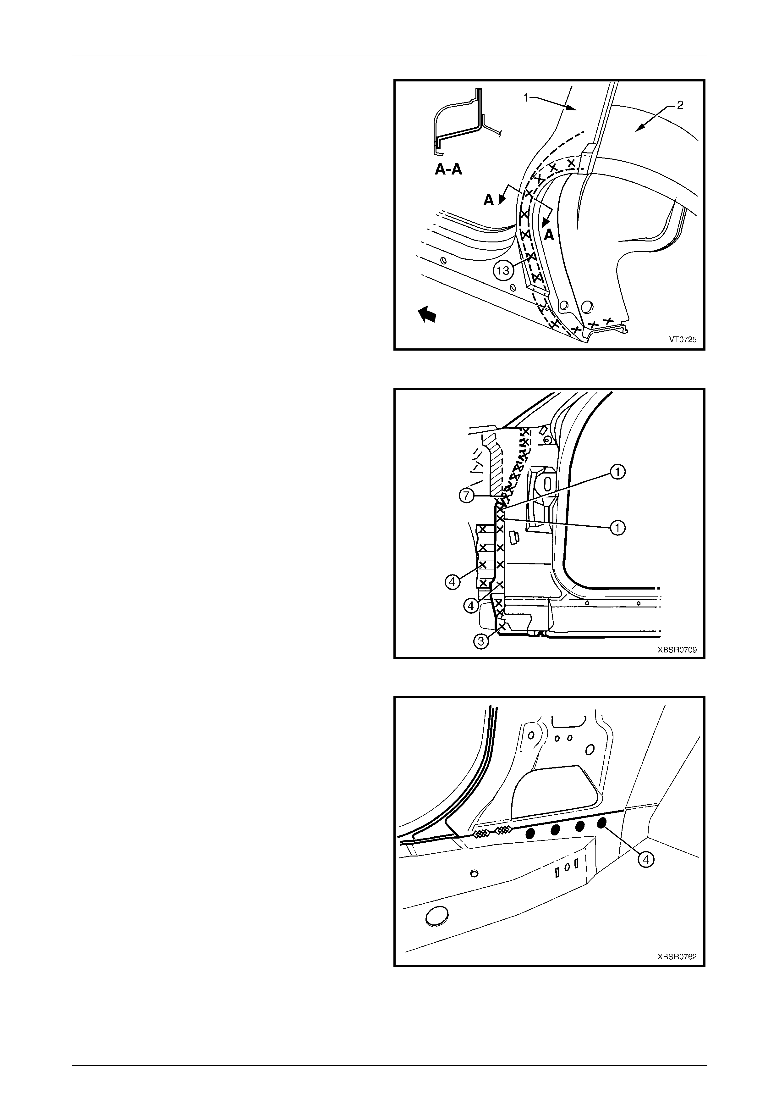
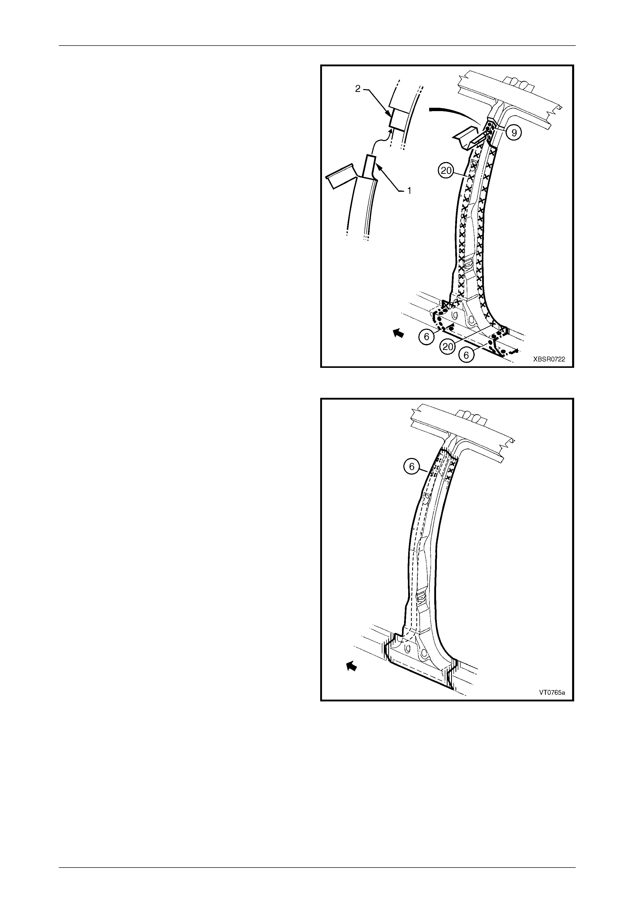
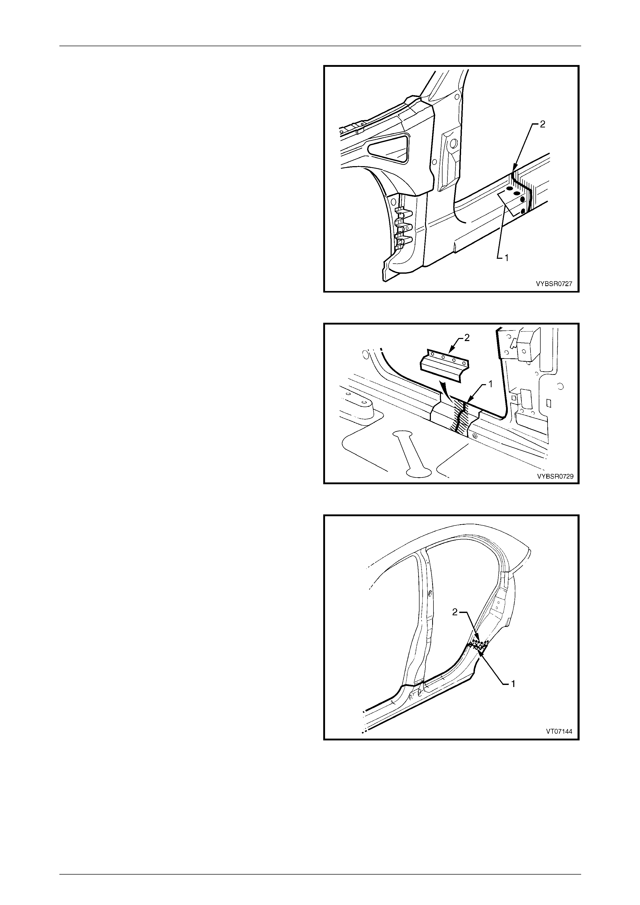
9 Spot cut the tail lamp housing brace from the tail lamp
housing (A) and rear quarter panel (B),
refer to Figure 7A – 8.
Figure 7A – 7
7A Body Side – Sedan Page 7A-7
Page 7A-7
Figure 7A – 8
NOTE
At the point at the base of the lock pillar, the r ear
quarter panel i s sand wiched bet ween t he q uarter
inner panel assembly and rear window panel
assembly. Cutting the panel at this point, as
described below, rather than removing extra
panels, will save considerable time and effort as
structural adhesive is used in this area.
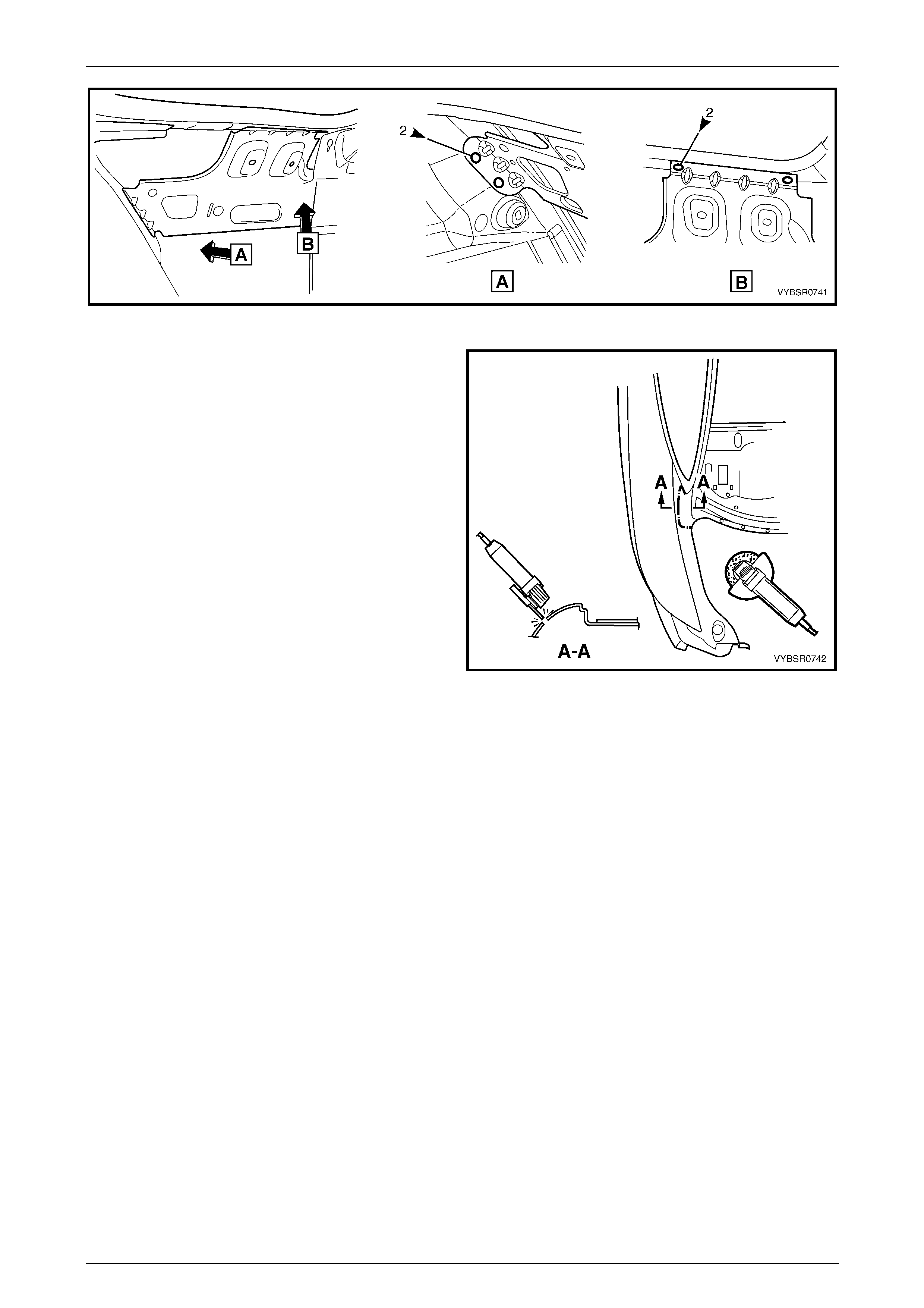
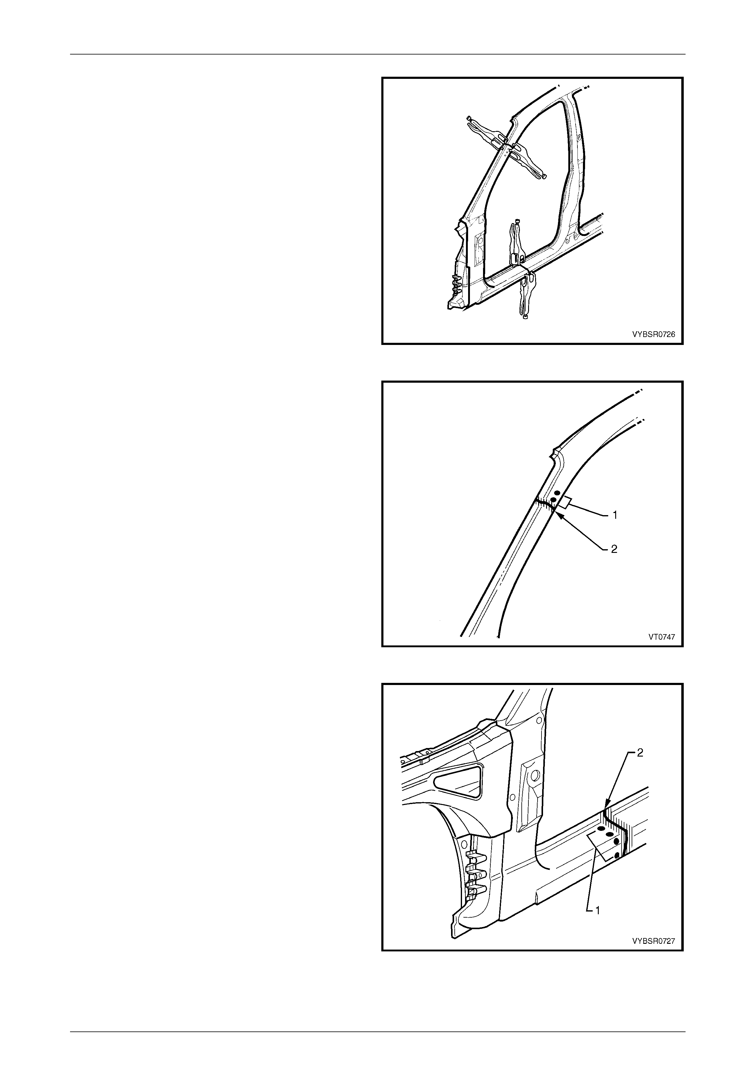
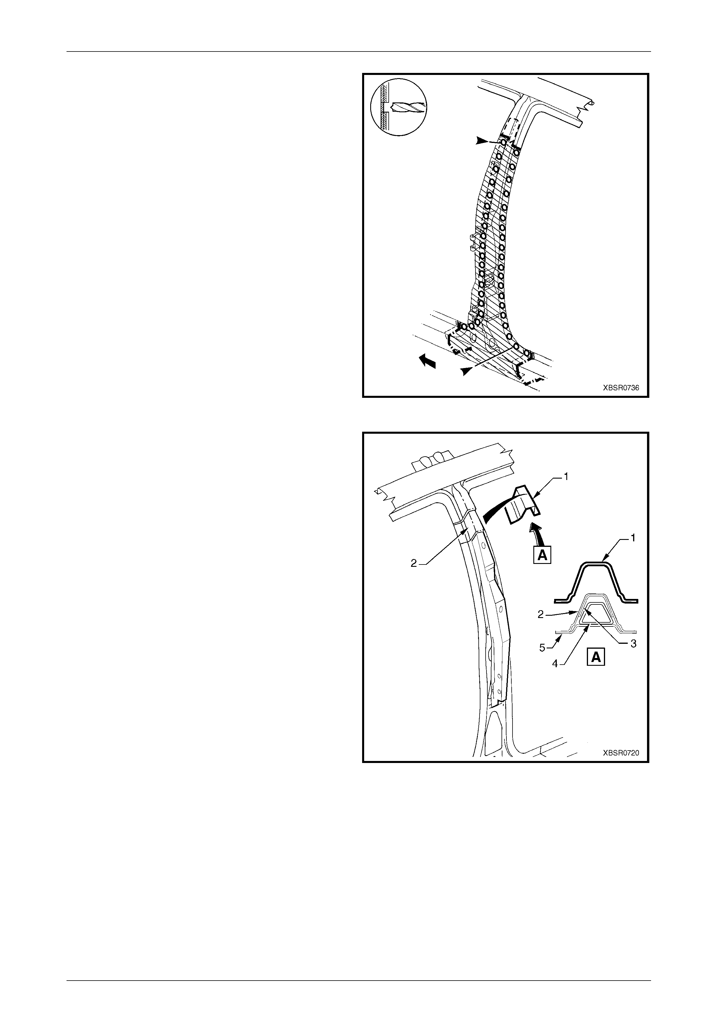
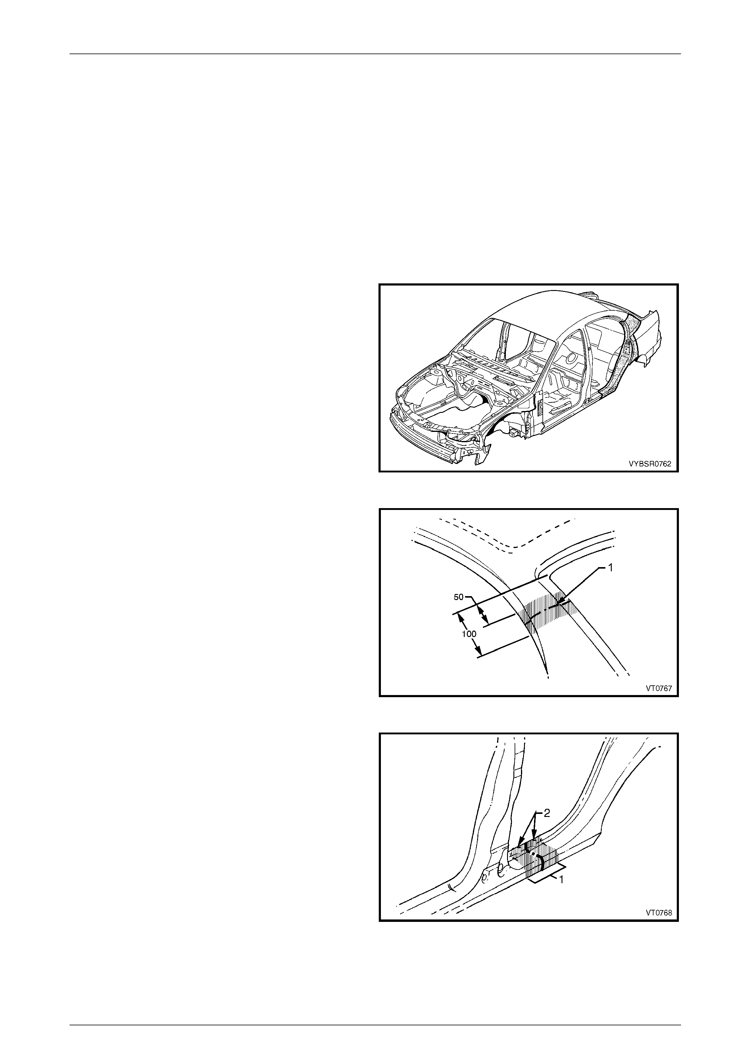
10 Using a saw or other appropr iate equipment, cut
through the rear quarter panel 40 – 50 mm from the
top edge. The cut should pass across the drain
channel, then along the visible face of the quarter
panel as illustrated, until the panel is detached from
the vehicle.
NOTE
It is important to leave enough material to
facilitate a lap joint of the old and new panels.
12 Remove the quarter panel from the vehicl e, then repair
any damage to adjacent parts.
NOTE
For the right-hand side, break or cut the acrylic
spot weld sealer attaching the fuel filler cap
housing.
13 Check and rectify the alignme nt of
the body as requir ed,
refer to Section 3A Body Construction – Sedan .
Figure 7A – 9
7A Body Side – Sedan Page 7A-8
Page 7A-8
Replace
NOTE
• Spot welding is the preferred method for
attaching of panels and should be used
whenever possible. Where the spot welding
equipment available will not access the
required weld position, a plug weld should be
performed.
• The same number and position of spot welds
(or plug welds) should be used when
replacing the panel, as was used during
manufacture, in order to maintain the original
structural strength of the vehicle.
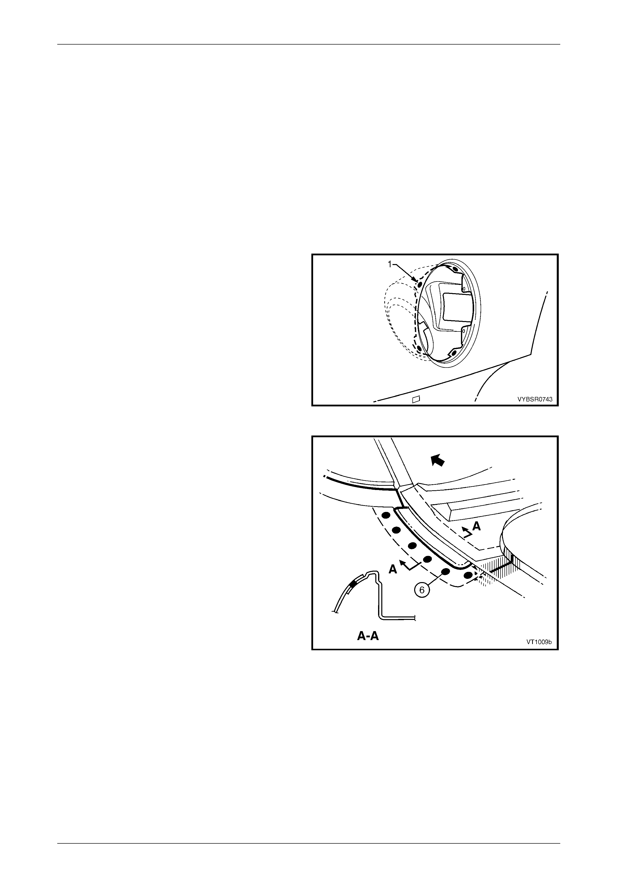
1 For the right-hand side, if required spot or plug weld
(1) the fuel filler pipe housing to the rear quarter panel
in four places.
Figure 7A – 10
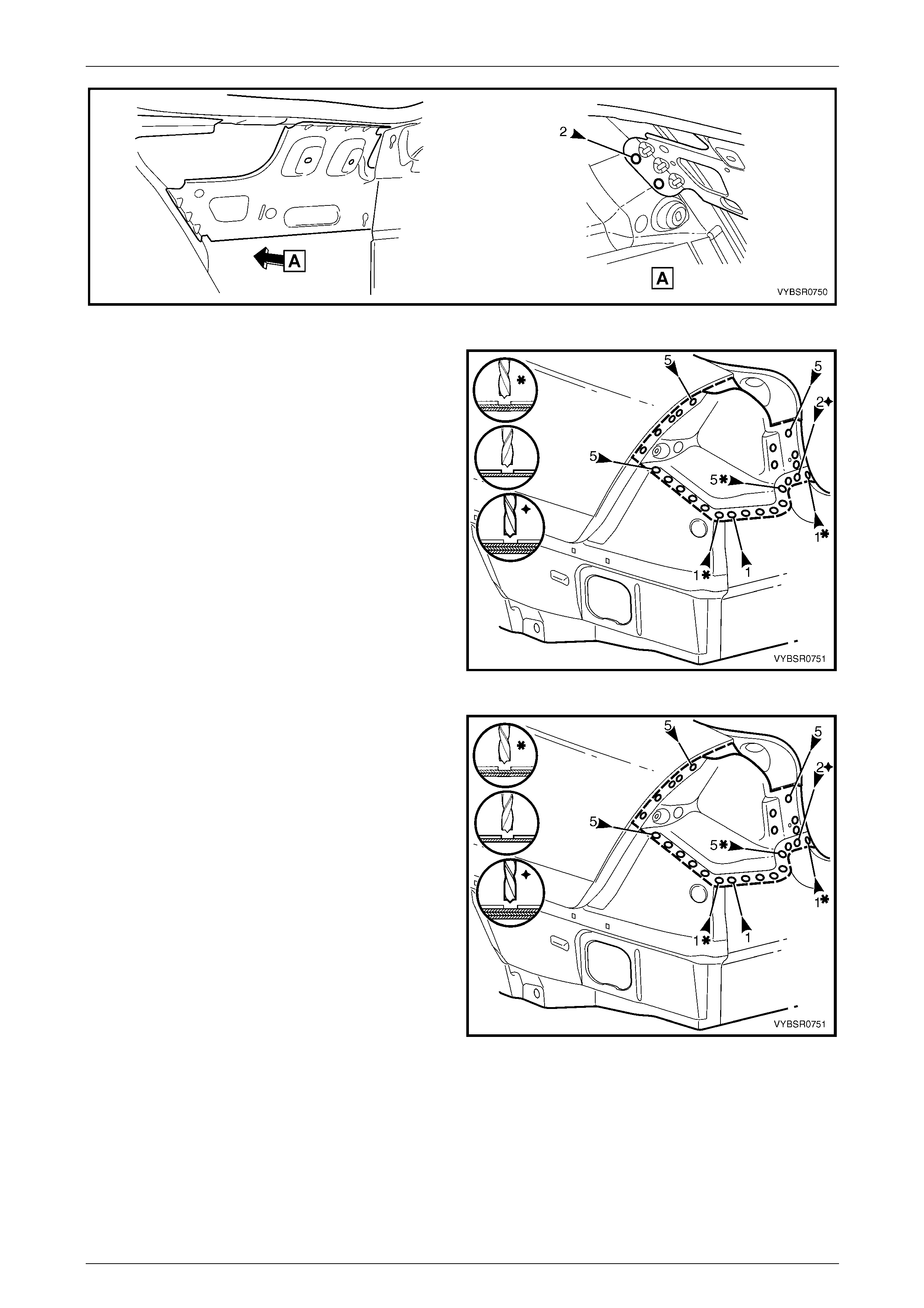
2 Joggle the remaining section of rear quarter panel to
match up to the new panel as shown.
3 Modify the new rear quarter panel to form the joint as
shown. The section of panel in the drain cha nnel is cut
to allow butt welding.
NOTE
Some replacement procedures for surrounding
panels require this section of the rear quarter
panel remain intact.
4 As required, mark the new panel with drilling locations
in preparation for plug welding. Drill holes as required.
5 Prepare all mating surfaces and treat with Weld
Through Primer (Item 1) as required,
refer to Section 3A Body Construction – Sedan .
6 Apply Acrylic Spot Weld Sealer (Item 2),
refer to Section 3A Body Construction – Sedan .
7 Clamp the rear quarter panel i n position and test fit the
alignment with the rear door and rear compartment lid.
8 Spot or plug weld the panels alo ng the lap joint, then
butt weld the joint inside the channel as shown.
Figure 7A – 11
7A Body Side – Sedan Page 7A-9
Page 7A-9
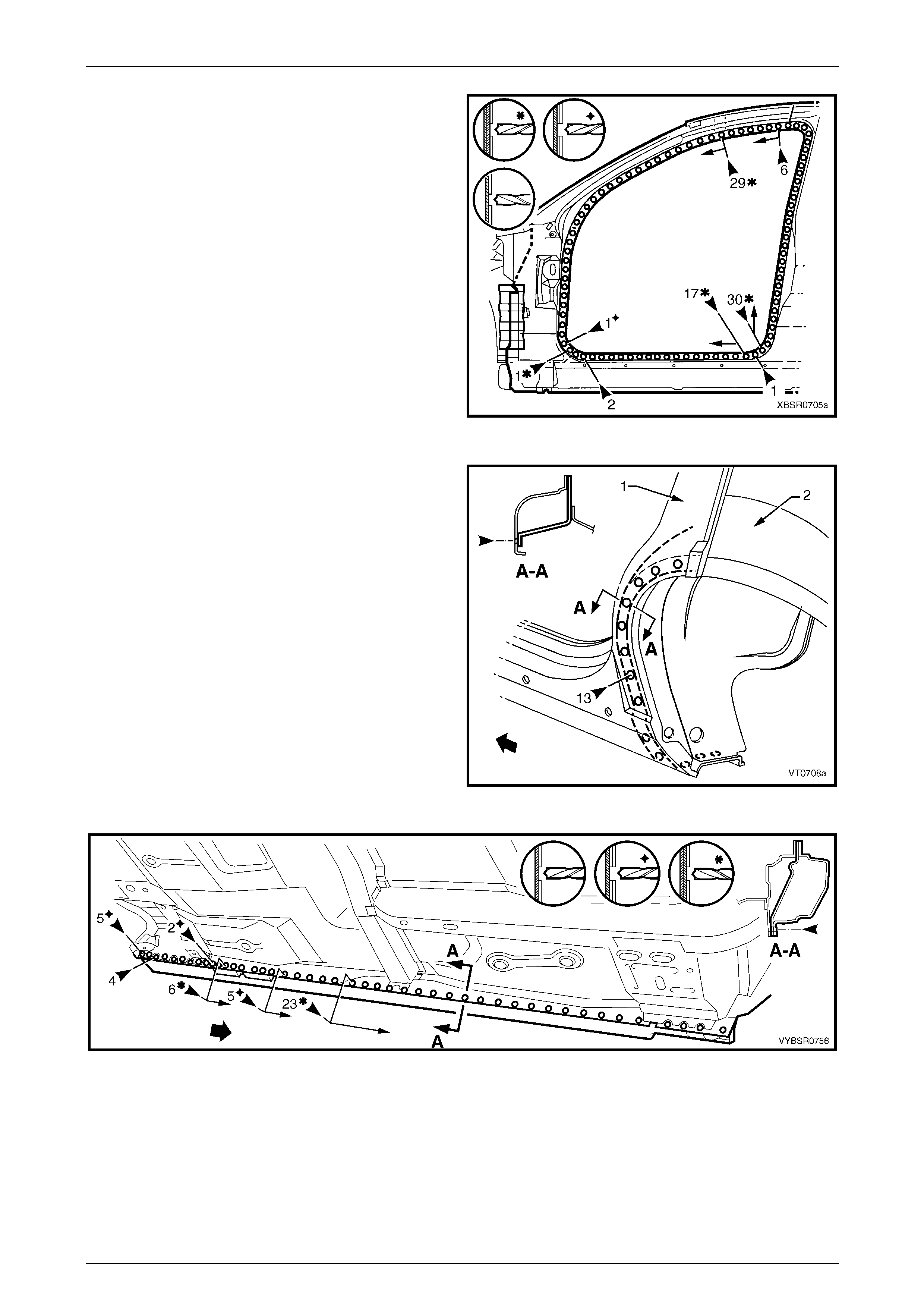
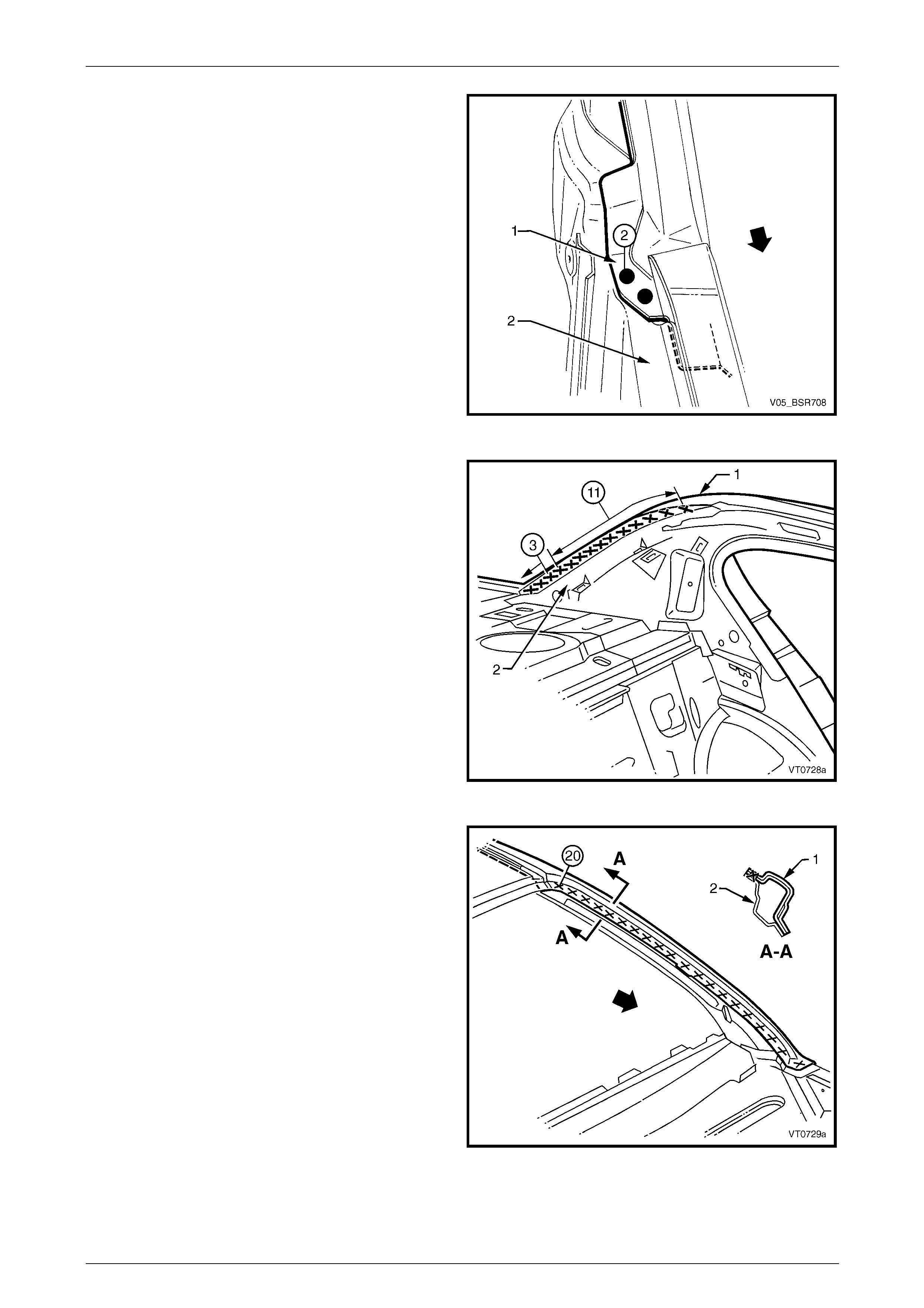
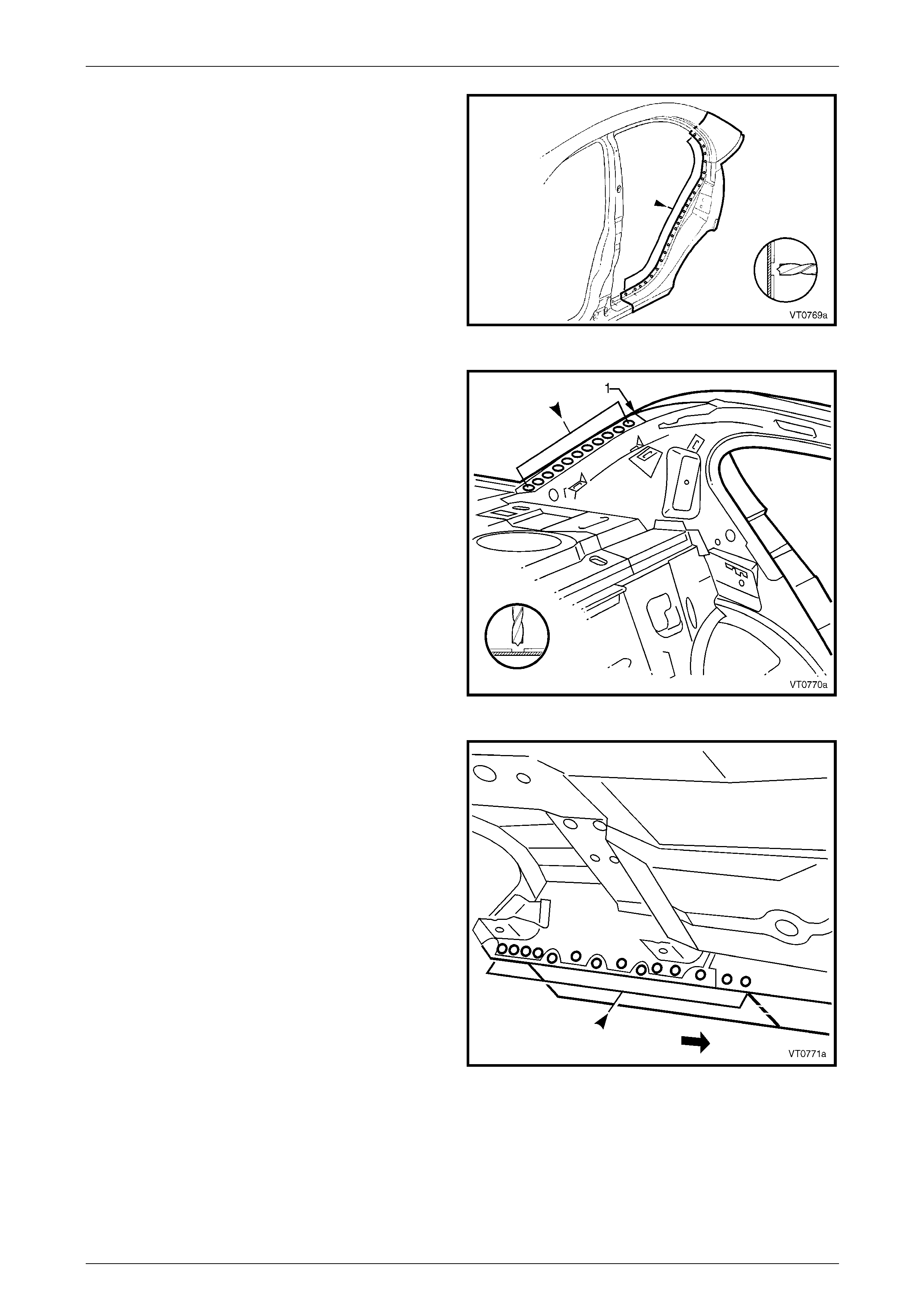
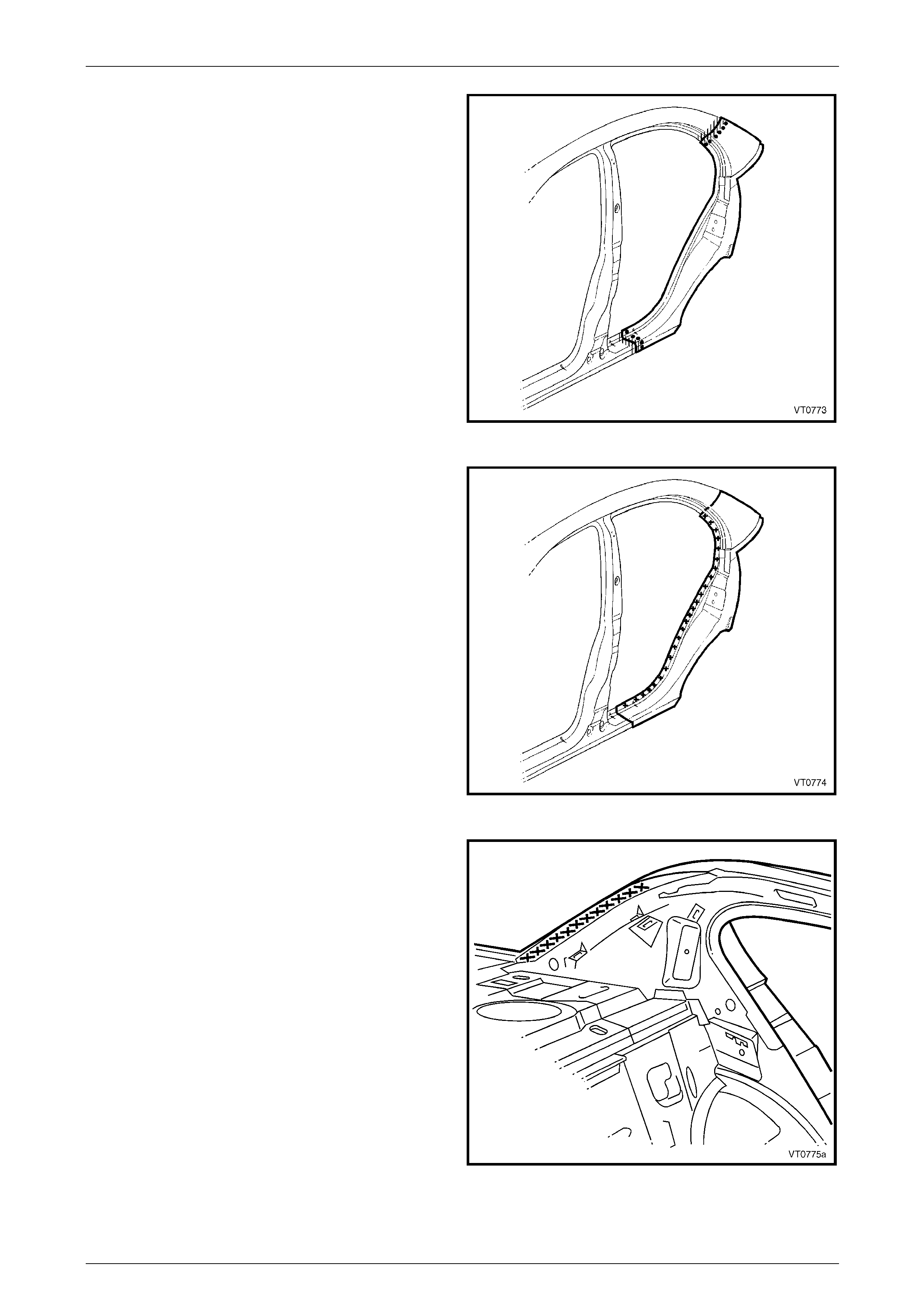
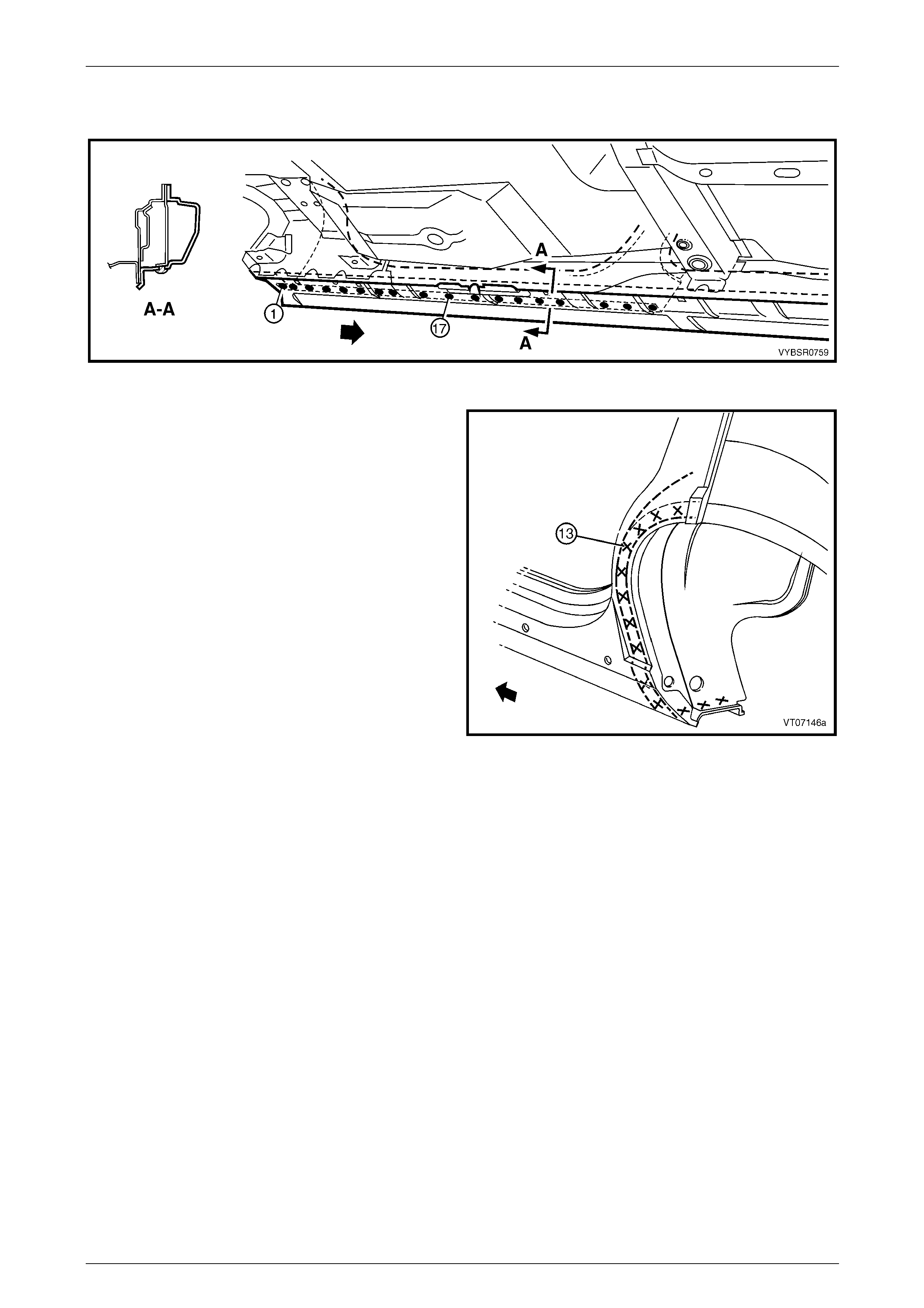
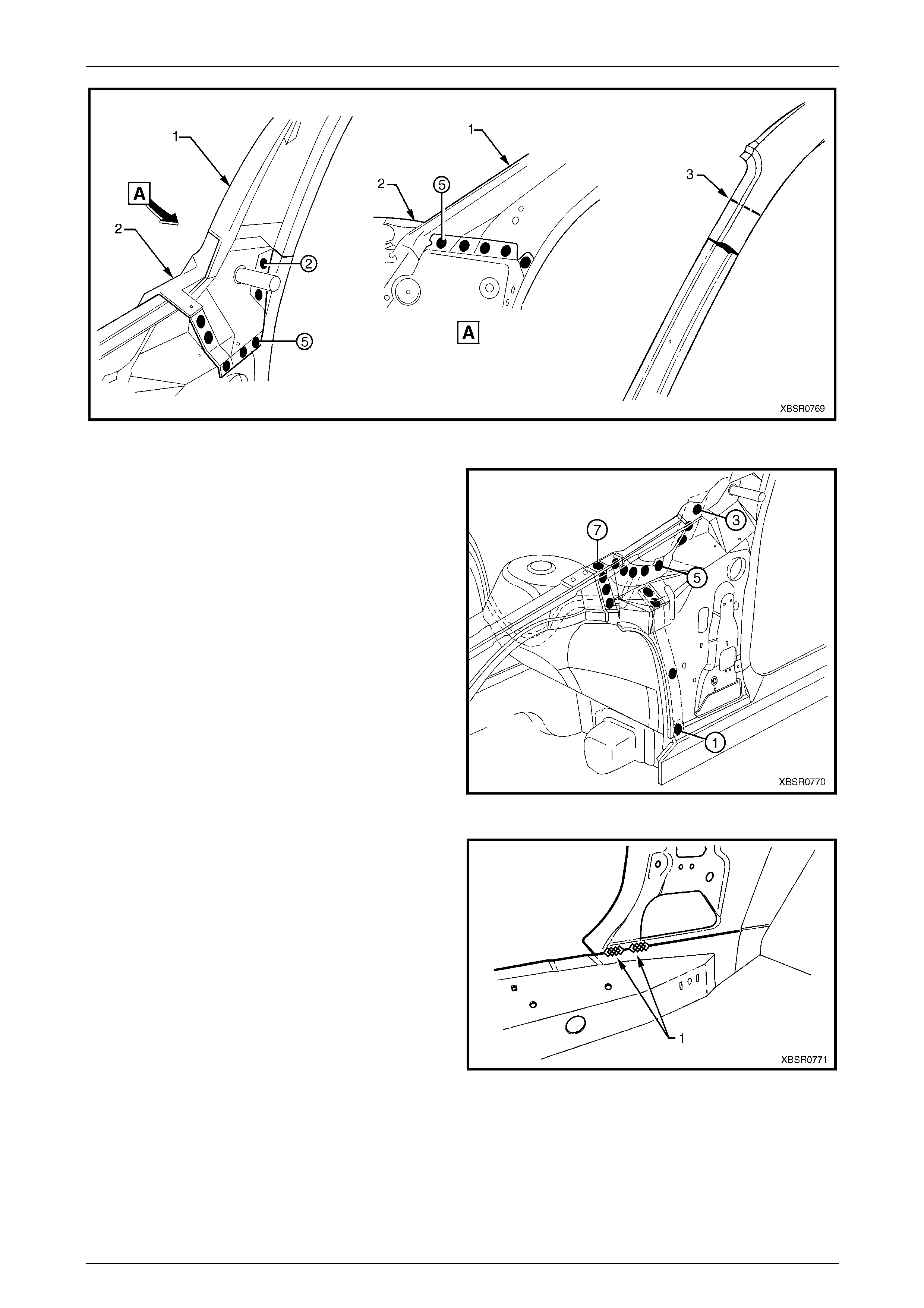
9 Spot or plug weld the rear quarter panel to the door
opening frame assembly.
10 Spot or plug weld the rear quarter panel to the quarter
inner panel assembly. There are a different n umber of
welds on the left-hand panel (1) to the right-hand
panel (2), refer to Figure 7A – 13.
Figure 7A – 12
Figure 7A – 13
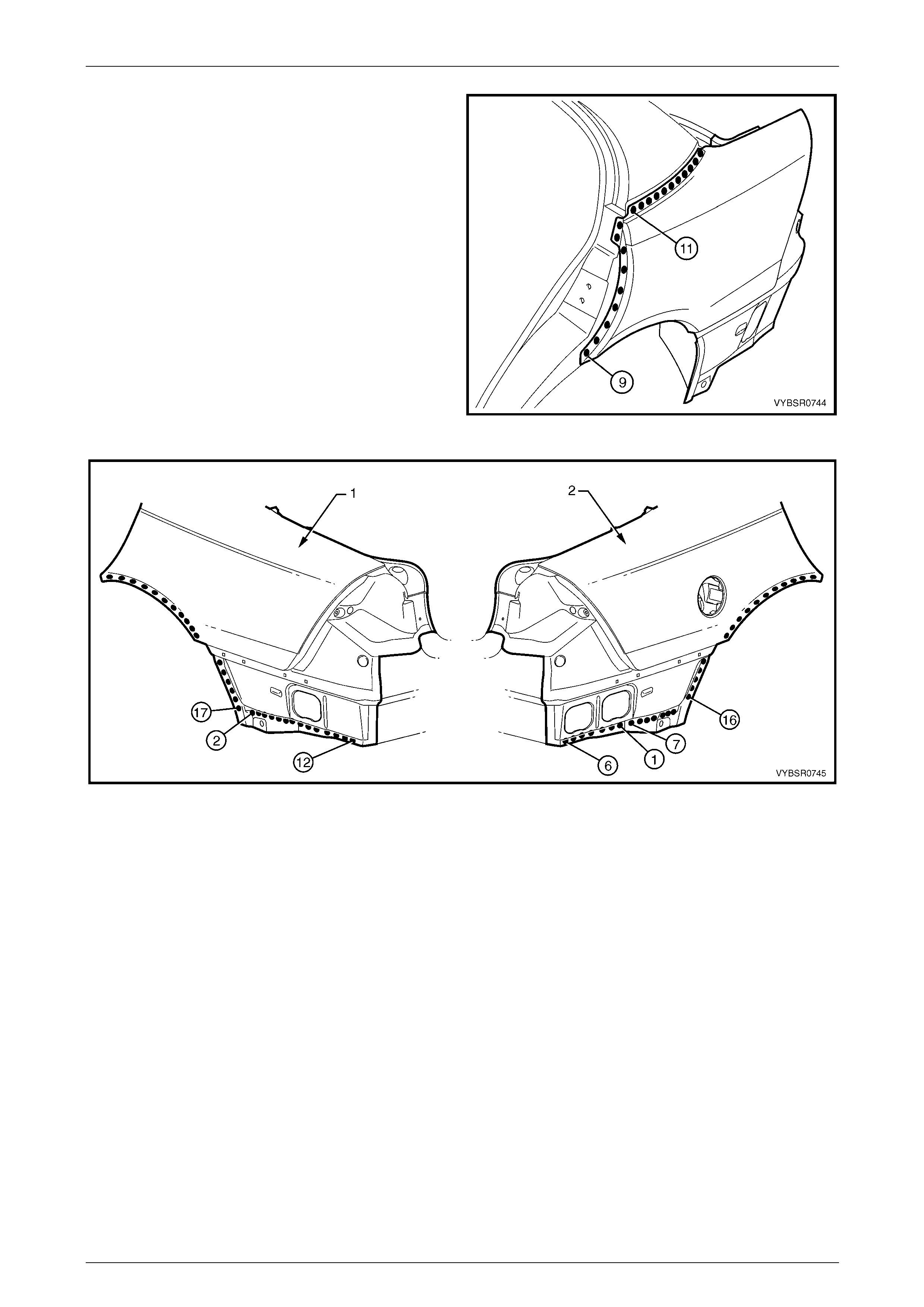
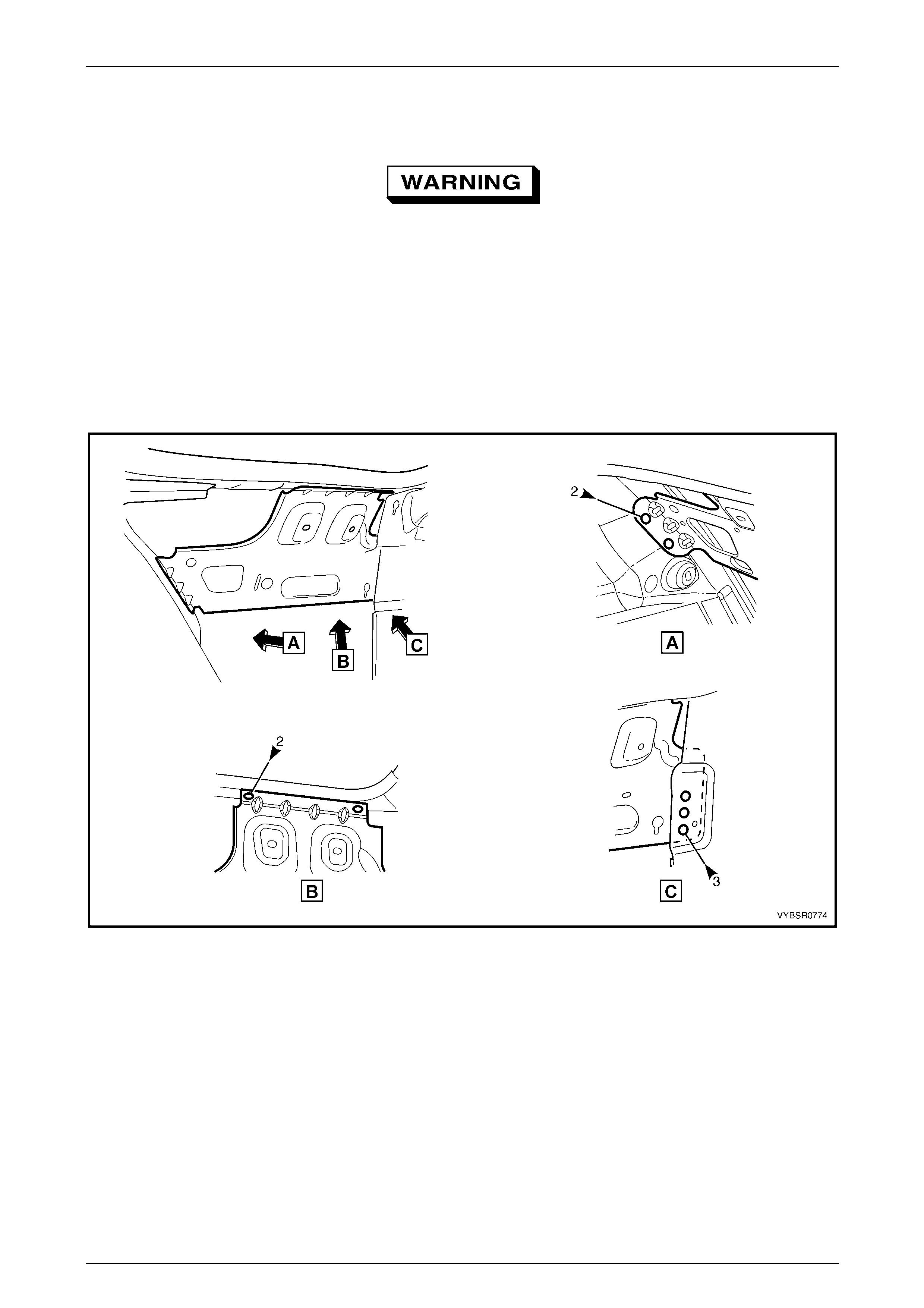
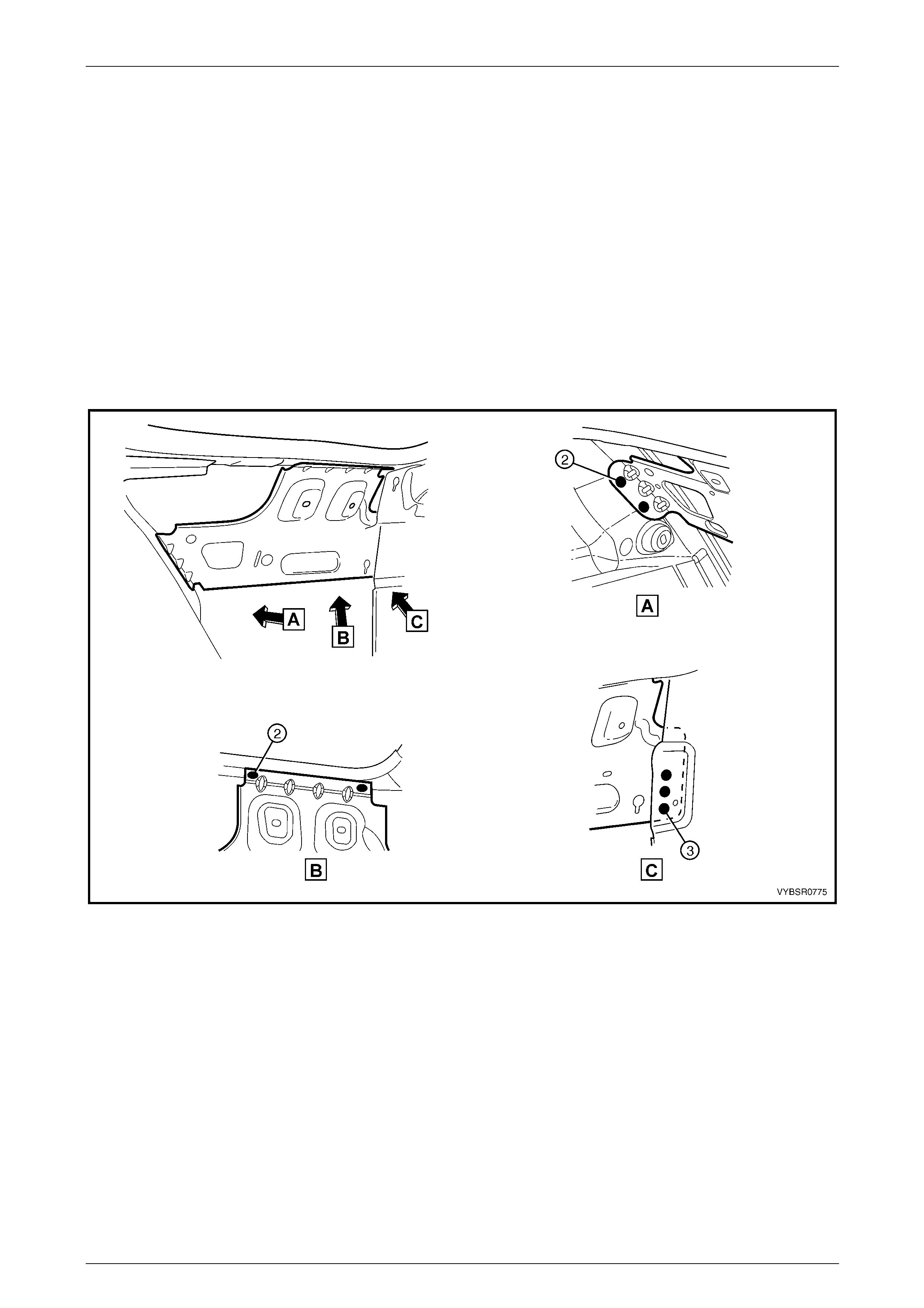
11 Spot or plug weld the tail lamp housing brace to the rear quarter panel.
NOTE
Complete the welds to the tail lamp housing once
it is installed in the following pr ocedure.
7A Body Side – Sedan Page 7A-10
Page 7A-10
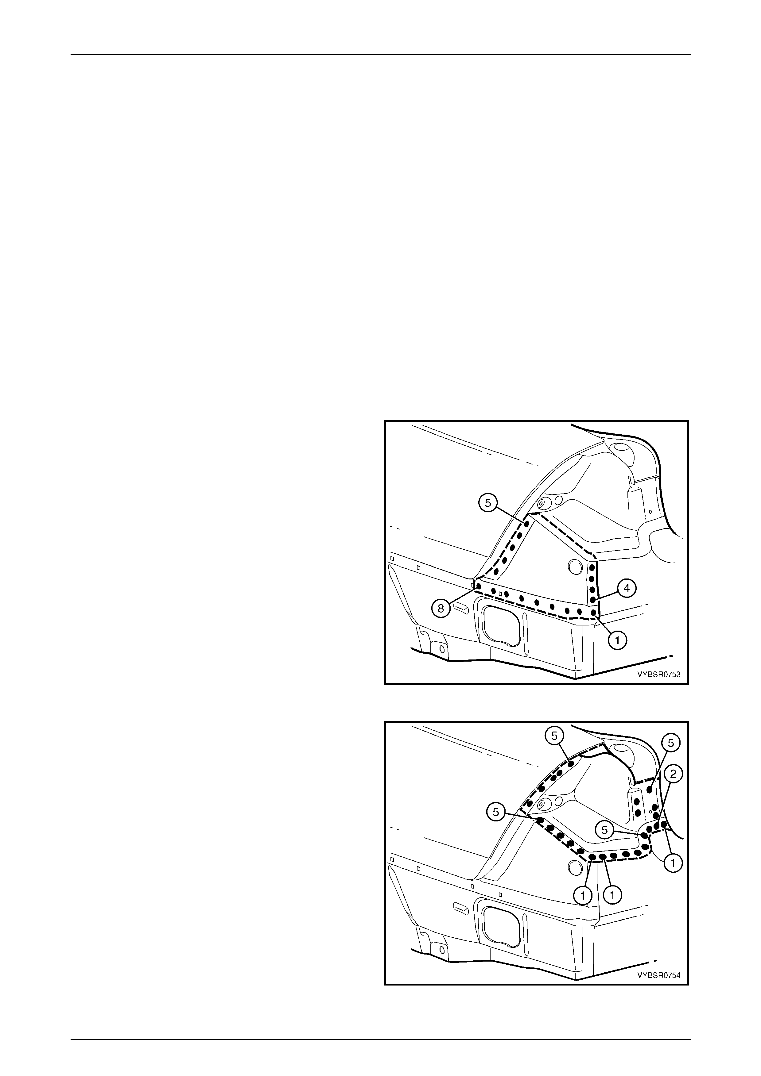
Figure 7A – 14
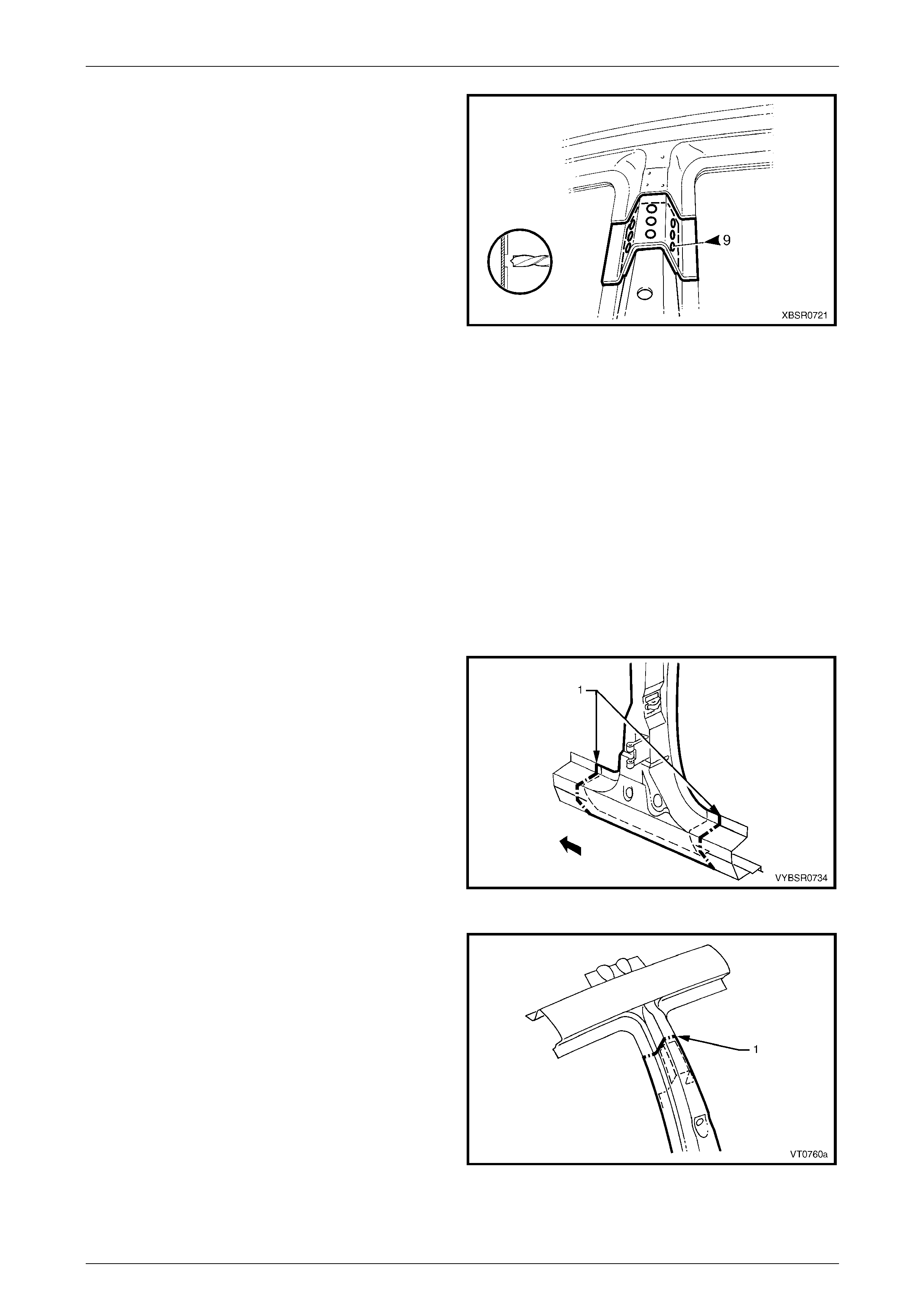
12 Spot or plug weld the rear quarter panel (1) to the rear
end lower panel (2).
13 Install the tail lamp housing, quarter panel upper and
lower extensions. Refer to the following procedur e.
14 Refinish and paint panels and other components as
required. Refer to Section 3 Body Construction .
15 Apply Joint Sealer (Item 3) as required.
Refer to Section 3A Body Construction – Sedan.
16 Apply Cavity Wax (Item 8) as required to the inside of
any box sections or areas inaccessible to paint,
refer to Section 3A Body Construction – Sedan .
17 Install rear bumper impact bar,
refer to Section 3 Body Construction.
18 Install the remaining components as described in the
MY 2005 VZ Service Information.
Figure 7A – 15
7A Body Side – Sedan Page 7A-11
Page 7A-11
2.2 Tail Lamp Housing, Quarter Panel Lower
Extension and Quarter Panel Upper
Extension – Replace
To avoid the possibility of fire, take particular
care when cuttin g or w elding at the r ear of th e
vehicle. Remove the fuel tank and plug the
fuel lines.
Remove
NOTE
The components descri bed in this pr ocedure may
be replaced as an assembly or individually as
required.
1 Remove the adjacent bolt-on panels a nd components
as described in the appropriate Section of th e MY
2005 VZ Service Information.
Figure 7A – 16
2 Spot cut the welds attaching the quarter panel upper
extension as required.
3 Spot cut the welds attaching the tail lamp housing
brace to the tail lamp housing, refer to Figure 7A-18.
Figure 7A – 17
7A Body Side – Sedan Page 7A-12
Page 7A-12
Figure 7A – 18
4 Spot cut the welds attaching the tail lamp housing to
the surrounding panels as requir ed.
Figure 7A – 19
5 Spot cut the welds attaching the quarter panel lower
extension to the surrounding panels as required.
6 Repair any damage to adjacent parts as required.
Figure 7A – 20
7A Body Side – Sedan Page 7A-13
Page 7A-13
Replace
NOTE
• Spot welding is the preferred method for
attaching of panels and should be used
whenever possible. Where the spot welding
equipment available will not access the
required weld position, a plug weld should be
performed.
• The same number and position of spot welds
(or plug welds) should be used when
replacing the panel, as was used during
manufacture, in order to maintain the original
structural strength of the vehicle.
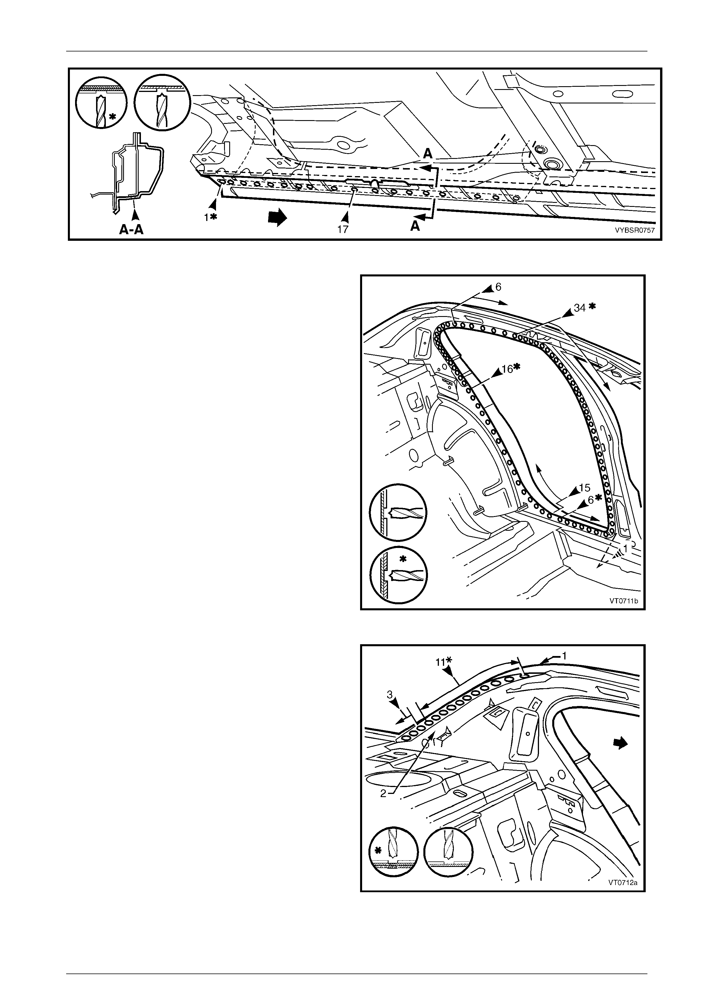
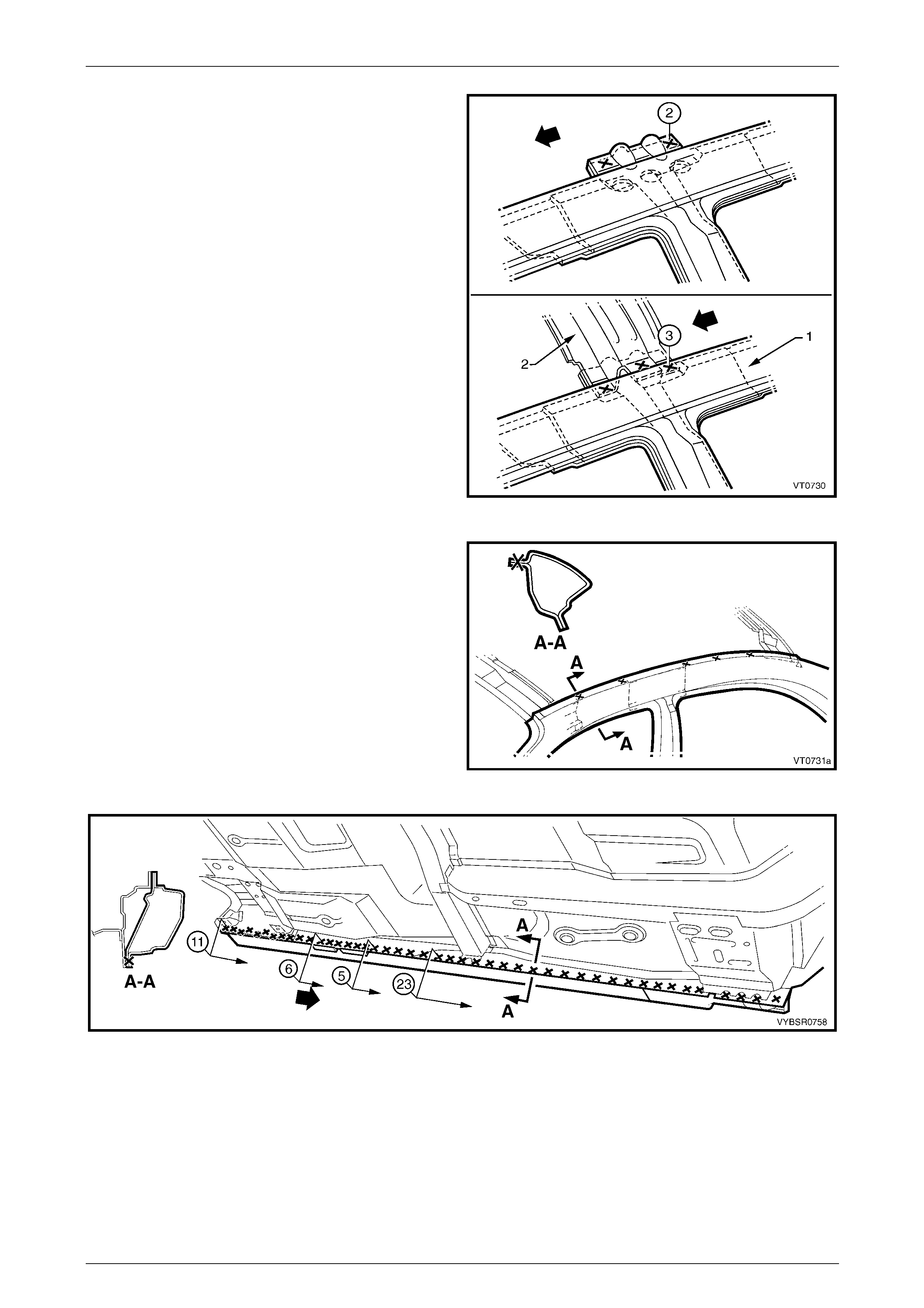
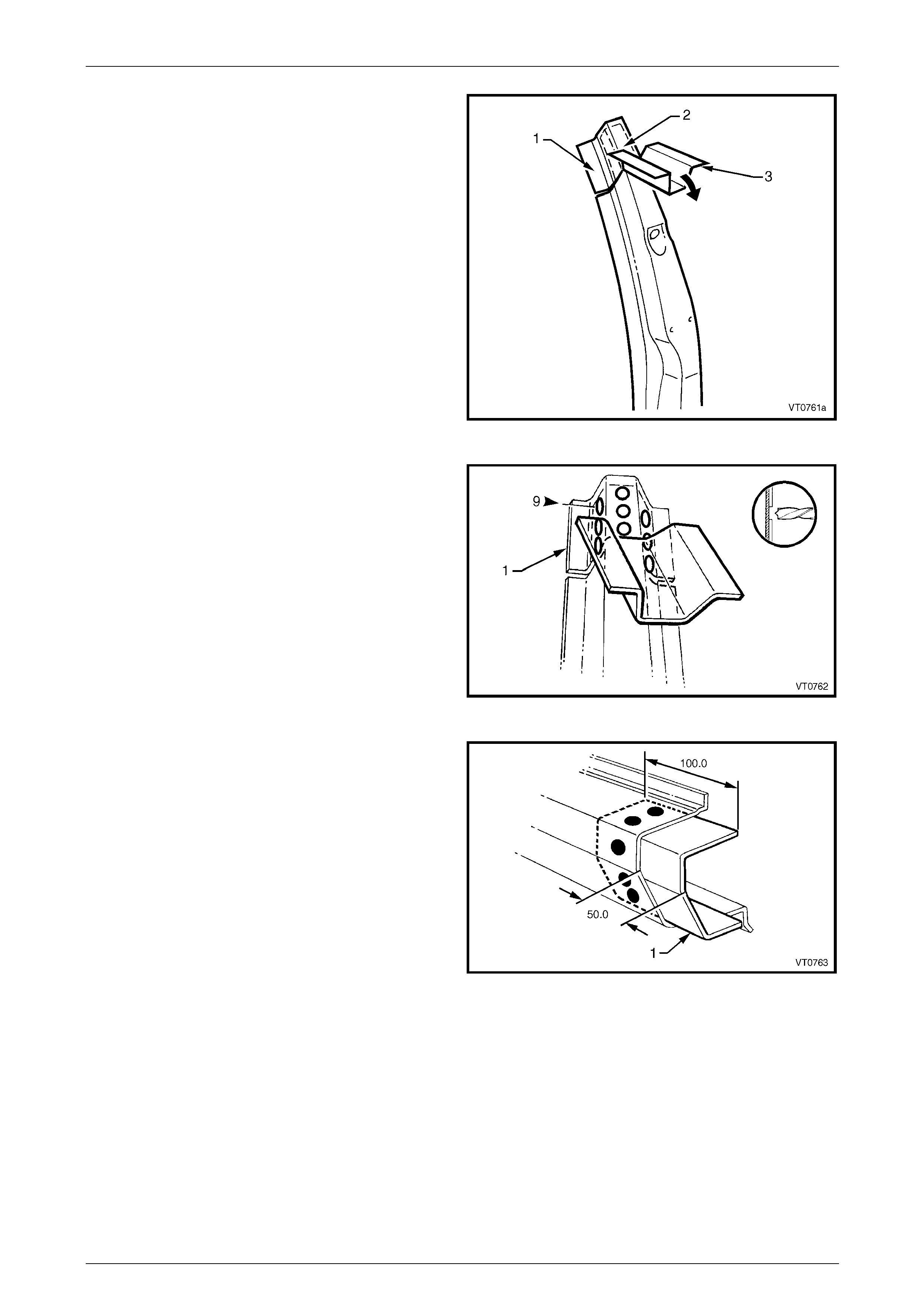
1 As required, mark the new panel with drilling locations in preparation for plug welding. Drill holes as required.
2 Prepare all mating surfaces and treat with Weld Through Primer (Item 1) as requir ed,
refer to Section 3A Body Construction – Sedan .
3 Apply Acrylic Spot Weld Sealer (Item 2), refer to Section 3A Body Construction – Sedan.
4 Clamp the removed parts in position and if required, temporarily install the tail lamp to check for correct fit with the
surrounding panels.
5 Spot or plug weld the quarter panel lower extension to
the surrounding panels as requir ed.
Figure 7A – 21
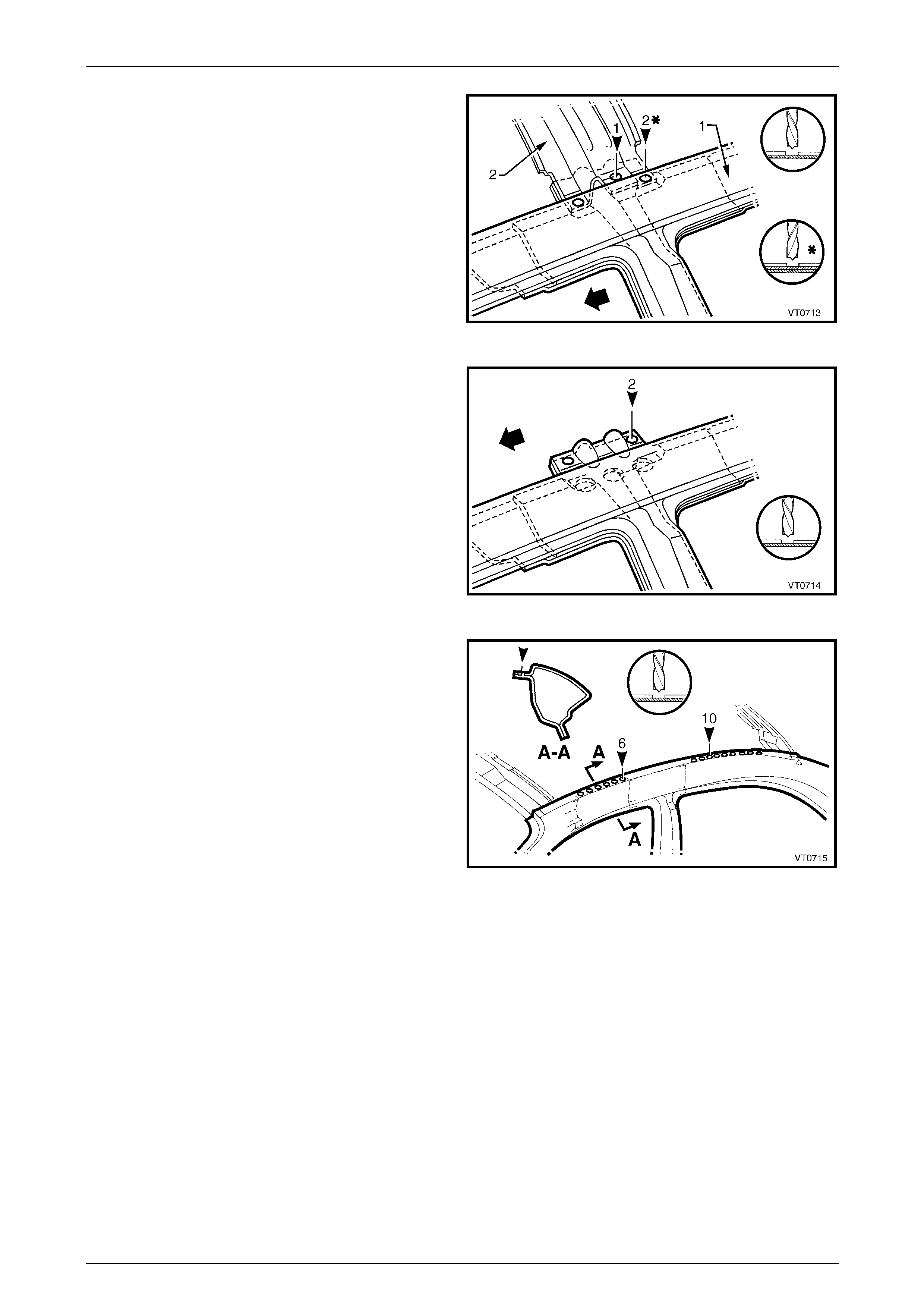
6 Spot or plug weld the tail lamp housing to the
surrounding panels as required.
7 Spot or plug weld the tail lamp hous ing brace to the
tail lamp housing, refer to Figure 7A – 23.
Figure 7A – 22
7A Body Side – Sedan Page 7A-14
Page 7A-14
Figure 7A – 23
8 Spot or plug weld the quarter panel u pper extension to
the surrounding panels as requir ed.
9 Refinish and paint panels and other components as
required. Refer to Section 3 Body Construction .
10 Apply Joint Sealer (Item 3) before the
top paint coats as required,
refer to Section 3A Body Construction – Sedan .
11 Apply Cavity Wax (Item 8) as required to the inside of
any box sections or areas inaccessible to paint,
refer to Section 3A Body Construction – Sedan .
12 Install the remaining components as described in the
appropriate Section of the MY 2005 VZ Servic e
Information.
Figure 7A – 24
7A Body Side – Sedan Page 7A-15
Page 7A-15
2.3 Tail Lamp Housing Brace – Replace
To avoid the possibility of fire, take particular
care when cuttin g or w elding at the r ear of th e
vehicle. Remove the fuel tank and plug the
fuel lines.
Remove
1 Remove the adjacent trim and components as described in the appropriate Section of the MY 2005 VZ Service
Information.
2 Spot cut the tail lamp housing brace from the tail lamp housing (A), rear quarter panel (B) and q uarter panel inner
assembly (C) as required, refer to Figure 7A – 25.
Figure 7A – 25
3 Remove the panel from the vehicle, and then repair an y damage to adjacent parts.
7A Body Side – Sedan Page 7A-16
Page 7A-16
Replace
NOTE
• Spot welding is the preferred method for
attaching of panels and should be used
whenever possible. Where the spot welding
equipment available will not access the
required weld position, a plug weld should be
performed.
• The same number and position of spot welds
(or plug welds) should be used when
replacing the panel, as was used during
manufacture, in order to maintain the original
structural strength of the vehicle.
1 Spot or plug weld the tail lamp housing brace to the tail lamp housing (A), rear quarter panel (B) an d quarter panel
inner assembly (C) as required, refer to Figure 7A – 26.
Figure 7A – 26
2 Refinish and paint panels and other components as required. Refer to Section 3 Body Construction.
3 Apply Joint Sealer (Item 3) as required. Refer to Section 3A Body Construction – Sedan.
4 Apply Cavity Wax (Item 8) as required to the inside of any box secti ons or areas inaccessible to paint,
refer to Section 3A Body Construction – Sedan .
5 Install the remaining compon ents as described in the MY 2005 VZ Servic e Information.
7A Body Side – Sedan Page 7A-17
Page 7A-17
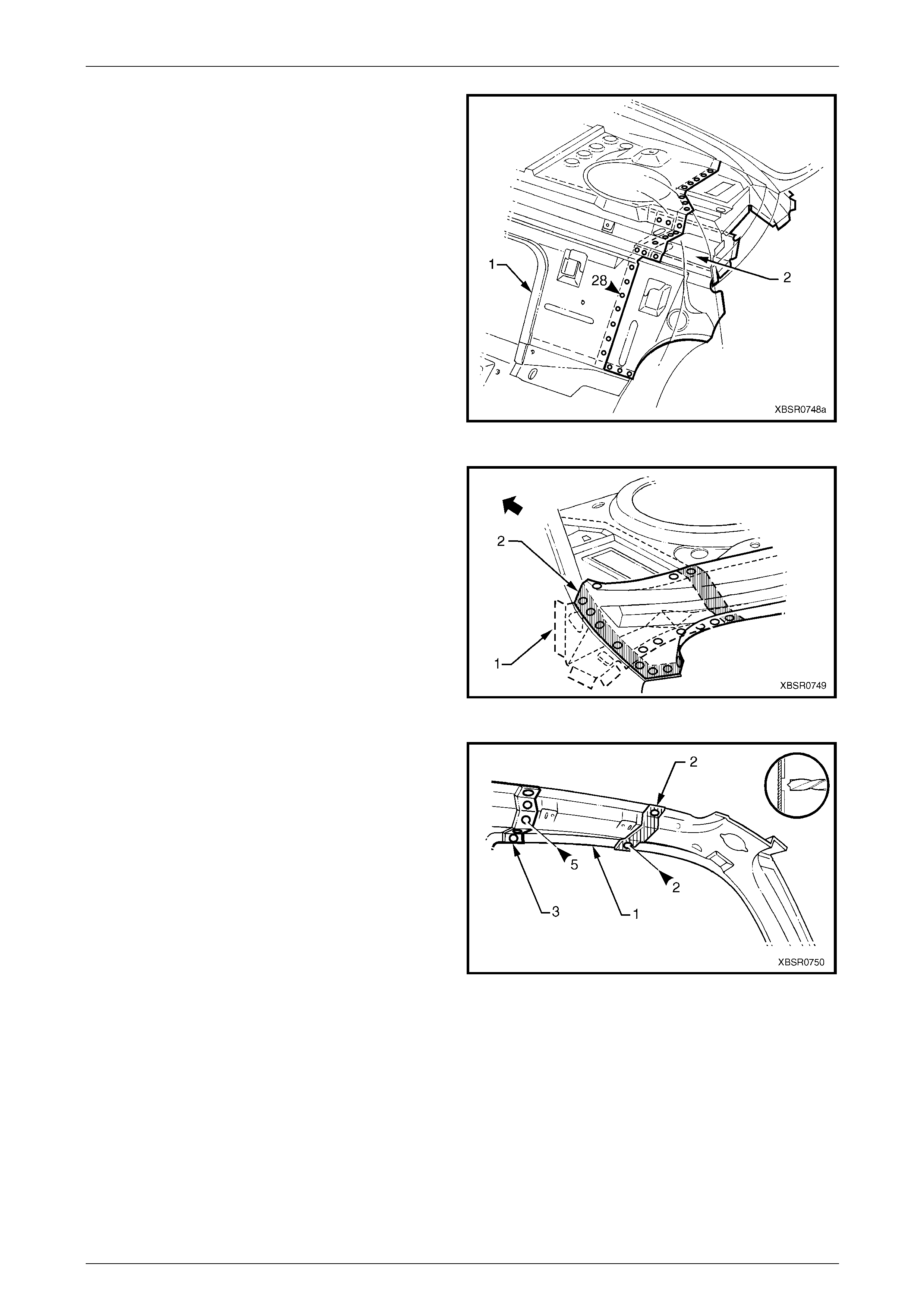
2.4 Door Opening Frame Assembly –
Replace
Remove
NOTE
• This procedure requires the removal of the
roof panel. As an alternative, the door
opening frame assembly can be cut at the
upper pillar sections by following the
procedures in 2.5 Door Opening Frame
Assembly – Partial Replace, Hinge Pillar,
2.6 Door Opening Frame Assembly – Partial
Replace. Centre Pillar and
2.7 Door Opening Frame Assembly – Partial
Replace, Lock Pillar.
• Cavity Foam is used within the hinge, centre
and lock pillar cavities. Care is required when
repairing the vehicle in these areas, refer to
Section 2 Precautions prior to beginning any
work for further information.
1 Remove the adjacent bolt-on panels a nd components
as described in the appropriate Service Information.
2 Remove the windshield and the rear window
assemblies, refer to Section 1A6 Stationary Windows
in the MY 2005 VZ Service Information.
3 Remove the dash panel retaining bolt from the hinge
pillar.
4 Remove the roof panel, refer to Section 9A Roof.
5 Remove the rear quarter panel,
refer to 2.1 Rear Quarter Panel – Replace.
6 Remove the front wheelhouse pan el upper side rail,
refer to Section 4 Front End. Figure 7A – 27
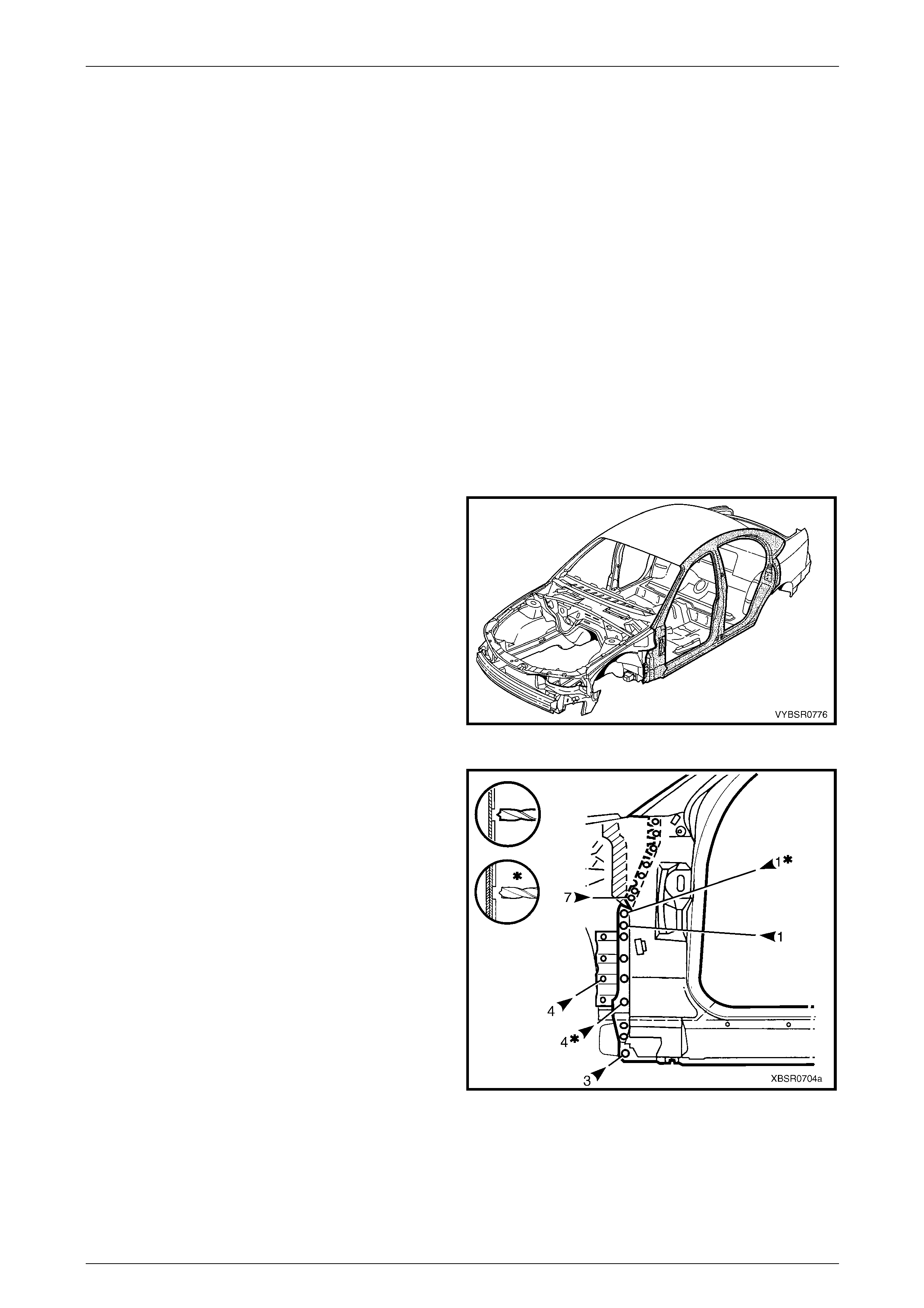
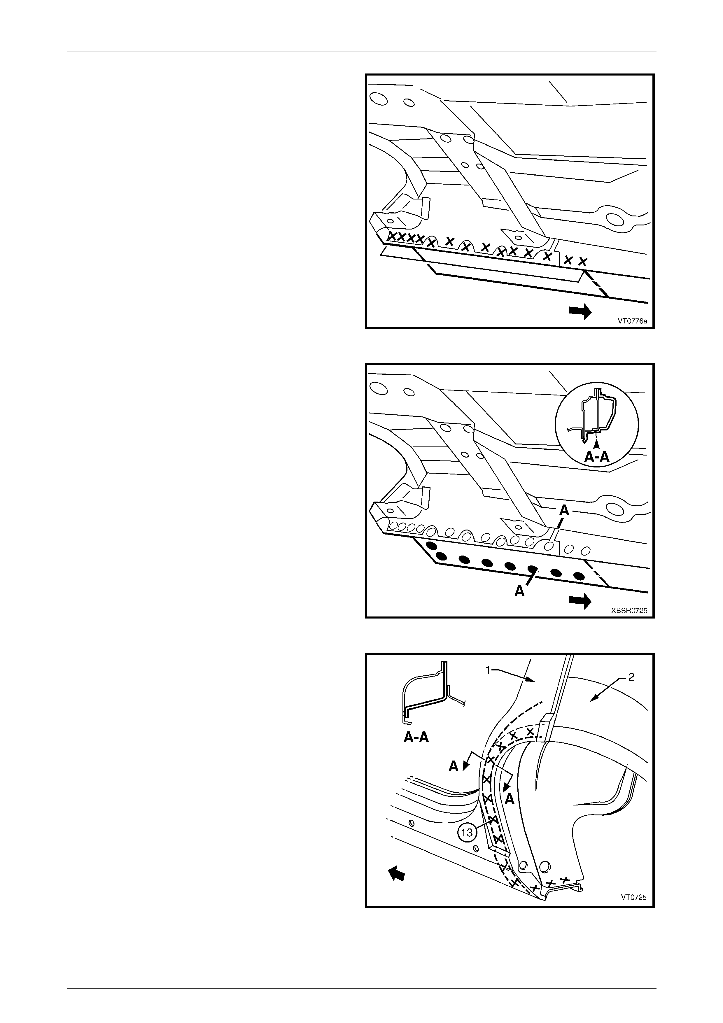
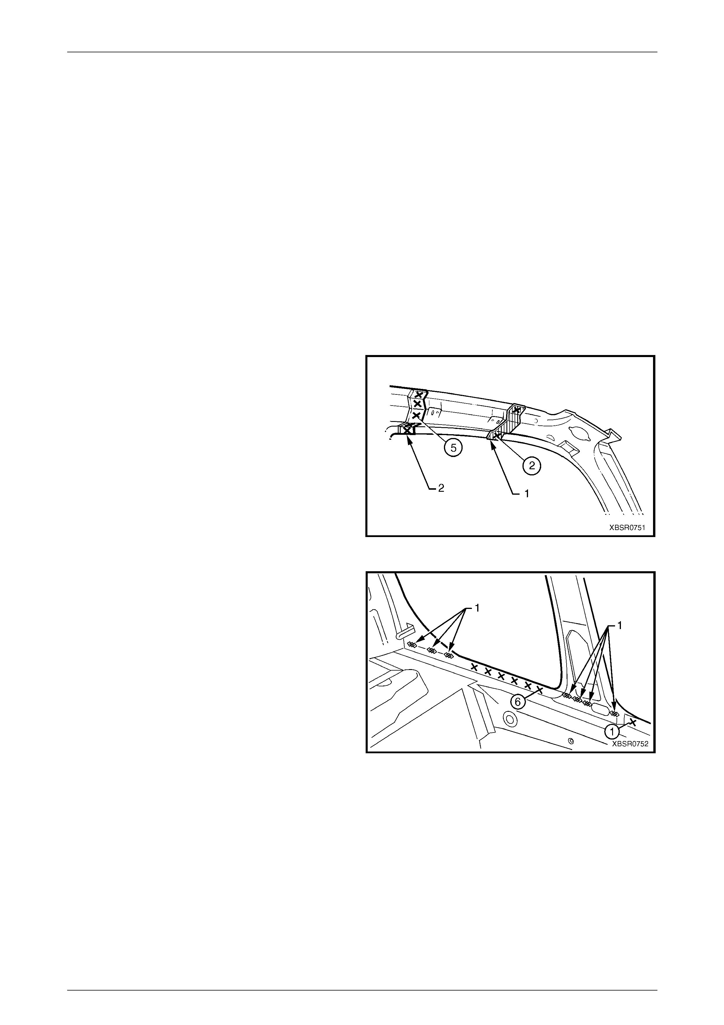
7 Spot cut the welds attaching the door openin g frame
assembly to the inner rocker panel and to the hin ge
pillar inner panel assembly.
NOTE
In order to spot cut the uppermost of these welds
it may be necessary to cut and peel back the
section of hinge reinforcement panel covering
the welds, to gain the required access.
8 Spot cut the welds attaching the inner rocker panel (1)
and hinge pillar inner p an el assembly (2) to the rocker
panel reinforcement (3). Refer to Figure 7A – 29.
NOTE
It is not required to cut the MIG welds.
Figure 7A – 28
7A Body Side – Sedan Page 7A-18
Page 7A-18
Figure 7A – 29
9 Spot cut the two welds at the base of the hinge pillar,
attaching the door opening frame assembly (1) to the
hinge pillar inner panel assembly (2).
Figure 7A – 30
10 Spot cut the welds on the windshield side flange,
attaching the door opening frame assembly (1) to the
hinge pillar inner panel assembly (2).
Figure 7A – 31
7A Body Side – Sedan Page 7A-19
Page 7A-19
11 Spot cut the welds on the flange surrounding the front
door opening, attaching the door op ening frame
assembly to the hinge pillar inner pa nel assembly,
inner rocker panel and quarter panel inner assembly.
Figure 7A – 32
12 Spot cut the welds around the rear wheel arch joining
the door opening frame assembly (1) to the quarter
panel inner assembly (2).
13 Spot cut along the vertical flange below the rocker
panel to separate the door opening frame assembly
from the inner rocker panel and rear floor p an el outer
extension. Refer to F igure 7A – 34.
Figure 7A – 33
Figure 7A – 34
14 Spot cut from below, up into the rocker panel, the welds attaching the door opening frame assembly to the quarter
panel inner assembly, refer to Figure 7A – 35.
7A Body Side – Sedan Page 7A-20
Page 7A-20
Figure 7A – 35
15 Spot cut the welds around the rear door opening
flange.
Figure 7A – 36
16 Spot cut the welds along the rear window flange
attaching the door opening frame assembly (1) to the
quarter panel inner assembly (2).
Figure 7A – 37
7A Body Side – Sedan Page 7A-21
Page 7A-21
17 Spot cut the two welds attaching the roof bow panel
(2) to the centre pillar upper reinforcement, and the
single weld attaching the roof bow panel to the door
opening frame assembly (1).
Figure 7A – 38
18 Carefully lifting the roof bow panel out of the way, spot
cut the two welds attaching the centre pillar upper
reinforcement to the quarter panel inn er asse mbly.
The centre pillar upper reinforcement is removed as
part of the door opening frame assembl y.
Figure 7A – 39
19 Spot cut the welds along the roof flange, attaching the
door opening frame assembly to the quarter p anel
inner assembly.
NOTE
Many welds may have been removed with the
roof panel.
20 Remove the complete door opening frame assembly
and repair any dama ge to adjacent parts.
21 Check and rectify the alignme nt of
the body as requir ed,
refer to Section 3A Body Construction – Sedan . Figure 7A – 40
7A Body Side – Sedan Page 7A-22
Page 7A-22
Replace
NOTE
• Spot welding is the preferred method for
attaching of panels and should be used
whenever possible. Where the spot welding
equipment available will not access the
required weld position, a plug weld should be
performed.
• The same number and position of spot welds
(or plug welds) should be used when
replacing the panel, as was used during
manufacture, in order to maintain the original
structural strength of the vehicle.
1 As required, mark the new panel with drilling locations in preparation for plug welding. Drill holes as required.
2 Prepare all mating surfaces and treat with Weld Through Primer (Item 1) as requir ed,
refer to Section 3A Body Construction – Sedan .
3 Apply Acrylic Spot Weld Sealer (Item 2), refer to Section 3A Body Construction – Sedan.
4 Securely clamp the door openin g frame assembly in
position on the vehicle body.
5 Begin attaching the door opening frame assembly by
spot welding around the front door opening flange.
Figure 7A – 41
6 Spot weld around the flange of the rear door opening.
Figure 7A – 42
7A Body Side – Sedan Page 7A-23
Page 7A-23
7 Spot or plug weld around the rear wheel arch,
attaching the door opening fram e assembly to the
quarter panel inner assembly.
Figure 7A – 43
8 Spot or plug weld the door opening frame assembly to
the inner rocker panel and to the hinge pillar inner
panel assembly. If the sheetmetal was modified to
allow access to these welds, it should be repaired to
its original configuration.
Figure 7A – 44
9 Plug weld the inner rocker pa nel and hinge pillar inner
panel assembly to the rocker panel reinforcement.
Figure 7A – 45
7A Body Side – Sedan Page 7A-24
Page 7A-24
10 Spot or plug weld the door opening frame assembly
(1) to the hinge pillar inner panel assembly (2) at the
base of the hinge pillar.
Figure 7A – 46
11 Spot or plug weld the rear windo w flange to the door
opening frame assembly (1) and qu arter panel inner
assembly (2).
Figure 7A – 47
12 Spot or plug weld along the windshield flange,
attaching the door opening frame assembly (1) to the
hinge pillar inner panel assembly (2).
Figure 7A – 48
7A Body Side – Sedan Page 7A-25
Page 7A-25
13 Spot or plug weld the door opening frame assembly
(1) to the quarter inner panel assemb ly, then spot or
plug weld the roof bow panel (2) to the door opening
frame assembly as shown.
Figure 7A – 49
14 Spot or plug weld the door opening frame assembly to
the quarter inner panel assembly along the roof panel
flange. Complete this flange when installing the roof
panel.
15 Spot or plug weld the door openi ng frame assembly
along the vertical flange below the rocker panel,
refer to Figure 7A – 51.
Figure 7A – 50
Figure 7A – 51
16 Plug weld up through the rocker panel to attach the door opening frame assembly to the quarter p anel inner
assembly. Refer to Figure 7A – 52.
7A Body Side – Sedan Page 7A-26
Page 7A-26
Figure 7A – 52
17 Replace front wheelhous e panel upper side rail, refer to Section 4 Front End.
NOTE
Refinish and prime any bare metal as required
prior to replacing these panel s.
18 Replace the rear quarter panel, refer to 2.1 Rear Quarter Pane l – Replace.
19 Replace the roof panel, refer to Section 9A Roof.
20 Install the door hinges, refer to Section 8 Do ors, Liftgate and Endgate.
21 Refinish and paint panels and other components as required. Refer to Section 3 Body Construction.
22 Apply Joint Sealer (Item 3) as required. Refer to Section 3A Body Construction – Sedan.
23 Apply Cavity Wax (Item 8) as required to the inside of any box secti ons or areas inaccessible to paint,
refer to Section 3A Body Construction – Sedan .
24 Apply Spray-on Dea dener (Item 7) where applicab le, refer to Section 3A Body Construc tion – Sedan.
25 Install the dash panel retaining bolt throu gh the hinge pil lar and tighten to the specified torque.
Dash Panel Retaining Bolt
Torque Specification ...............................35.0 – 45.0 Nm
26 Replace the windshield and the rear window assembly, refer to Section 1A 6 Stationary Windows in the MY 2005
VZ Service Information.
27 Insert Cavity Foam into the hinge and centre pillars as required, refer to Section 2 Precautions.
28 Install the remaining components as described in the appropriate Section of the MY 2005 VZ Service Information.
7A Body Side – Sedan Page 7A-27
Page 7A-27
2.5 Door Opening Frame Assembly – Partial
Replace, Hinge Pillar
A sunroof option is available that is fitted on
the production line. To cater for this option, a
stainless steel front drain tube is also fitted
within the hinge pillar cavity, therefore the
partial replacement procedure for the hinge
pillar must not be performed on these
vehicles.
NOTE
Cavity Foam is used within the hinge, centre and
lock pillar cavities. Care is required when
repairing the vehicle in these areas, refer to
Section 2 Precautions prior to beginning any work
for further information.
Remove
1 Remove the adjacent bolt-on panels a nd components
as described in the appropriate Section of th e MY
2005 VZ Service Information.
2 Secure an appropriate tool between the front door
opening flanges to maintain correct bod y alignment.
3 Remove the windshield, refer to Section 1A6
Stationary Windows in the MY 2005 VZ Service
Information.
4 Remove the dash panel retaining bolt from the hinge
pillar.
5 Remove the front wheelhouse pan el upper side rail,
refer to Section 4 Front End. Figure 7A – 53
6 Spot cut the welds attaching the door openin g frame
assembly to the inner rocker panel and to the hin ge
pillar inner panel assembly.
NOTE
In order to spot cut the uppermost of these welds
it may be necessary to cut and peel back the
section of hinge reinforcement panel covering
the welds, to gain the required access.
7 Spot cut the welds attaching the inner rocker panel (1)
and hinge pillar inner p an el assembly (2) to the rocker
panel reinforcement (3). Refer to Figure 7A – 55.
NOTE
It is not required to cut the MIG welds.
Figure 7A – 54
7A Body Side – Sedan Page 7A-28
Page 7A-28
Figure 7A – 55
8 Spot cut the two welds at the base of the hinge pillar,
attaching the door opening frame assembly (1) to the
hinge pillar inner panel assembly (2).
Figure 7A – 56
9 Select a cutting point on the hinge pillar. This cut point
should be within the region specified.
Figure 7A – 57

7A Body Side – Sedan Page 7A-29
Page 7A-29
10 At the selected point (1), cut through the outer and
reinforcement panels, leaving the inner panel intact.
11 Mark the inner panel at points 50 mm either side of the
cut line on the outer panel and cut the inner panel at
these two points (2). Spot cut the welds and remove
the 100 mm section of inner panel (3).
Figure 7A – 58
12 Spot cut the welds on the windshield side flange, up to
the point of the cut.
Figure 7A – 59
13 Cut through the rocker panel section of the door
opening frame assembly. The cut point (1) sh ould be
through the third rocker panel moulding attaching hole
(2). Cut through both the outer panel and the
reinforcement.
Figure 7A – 60
7A Body Side – Sedan Page 7A-30
Page 7A-30
14 Spot cut the welds on the flange along the front door
opening, from the cut near the top of the hinge pill ar
(1) to the cut in the rocker panel (2).
15 Spot cut the welds along the flange (3) below the
rocker panel to the point of the cut.
16 Remove the partial hinge p illar from the vehicle, then
repair any damage to adjacent parts.
17 Check and rectify the alignme nt of
the body as requir ed,
refer to Section 3A Body Construction – Sedan .
Figure 7A – 61
Replace
NOTE
• Spot welding is the preferred method for
attaching of panels and should be used
whenever possible. Where the spot welding
equipment available will not access the
required weld position, a plug weld should be
performed.
• The same number and position of spot welds
(or plug welds) should be used when
replacing the panel, as was used during
manufacture, in order to maintain the original
structural strength of the vehicle.
1 Cut a replacement panel section (1), accurately
measuring the position of cuts to match the section
removed.
Figure 7A – 62
7A Body Side – Sedan Page 7A-31
Page 7A-31
2 Remove a section of inner rocker panel (1). Cut
50 mm each side of the cut in the rocker panel. T his
allows access for welding the rocker panel
reinforcement.
Figure 7A – 63
3 Either manufacture a new section or cut an existing
length of surplus rocker panel section, to form a
reinforcement (1), approximately 100 mm in length.
4 Prepare all mating surfaces and treat with Weld
Through Primer (Item 1) as required,
refer to Section 3A Body Construction – Sedan .
5 Clamp this reinforcement firmly behind the cut section
of rocker panel on the vehicle and spot or plug weld in
place. Position welds at a maximum spacing of 35 mm
apart.
Figure 7A – 64
6 Using a similar technique, ma nufacture or cut a
section of reinforcement panel (1) appro ximat ely
60 mm long, to fit on the inside the outer panel of the
replacement hinge pillar (2) at the point of th e cut.
NOTE
Remove the flanges from this reinforcement
panel.
7 Prepare all mating surfaces and treat with Weld
Through Primer (Item 1) as required,
refer to Section 3A Body Construction – Sedan .
8 Clamp the reinforcement panel firmly behind the outer
panel of the cut section of the hinge pillar and spot
weld (3) in place.
9 Mark the new hinge pillar with drilling locations in
preparation for plug welding where required. Drill holes
as marked.
10 Prepare all mating surfaces and treat with Weld
Through Primer (Item 1) as required,
refer to Section 3A Body Construction – Sedan .
11 Apply Acrylic Spot Weld Sealer (Item 2),
refer to Section 3A Body Construction – Sedan .
Figure 7A – 65
7A Body Side – Sedan Page 7A-32
Page 7A-32
12 Clamp the replacement panel (1) in position on the
vehicle and check the door opening dimensions.
Refer to Section 3A Body Construction – Sedan.
Adjust position as required.
Figure 7A – 66
13 Plug weld (1) the top of the pillar to the manufactured
reinforcement, then MIG butt weld (2) the two sections
together.
Figure 7A – 67
14 Plug weld (1) the new panel in the rocker panel region,
then MIG butt weld (2) the two sections together.
Figure 7A – 68

7A Body Side – Sedan Page 7A-33
Page 7A-33
15 Gaining access through the removed sectio n of inner
panel, MIG butt weld (1) the reinforcement panel
together.
16 Butt weld the removed access panel (2) in position.
Replace the spot welds with the same number that
was removed.
Figure 7A – 69
17 Spot weld (1) the hinge pillar section along the door
opening flange.
18 Spot weld (2) the flange beneath the rocker pan el,
attaching the new panel to the inner rocker panel.
Figure 7A – 70
19 Spot weld (1) the pillar along the windshield opening
flange.
Figure 7A – 71
7A Body Side – Sedan Page 7A-34
Page 7A-34
20 Spot or plug weld the door opening frame assembly
(1) to the hinge pillar inner panel assembly (2) at the
base of the hinge pillar.
Figure 7A – 72
21 Spot or plug weld the door opening frame assembly to
the inner rocker panel and to the hinge pillar inner
panel assembly. If the sheetmetal was modified to
allow access to these welds, it should be repaired to
its original configuration.
Figure 7A – 73
22 Plug weld the inner rocker pa nel and hinge pillar inner
panel assembly to the rocker panel reinforcement.
Figure 7A – 74
7A Body Side – Sedan Page 7A-35
Page 7A-35
23 Gaining access through the section of removed in ner
rocker panel, MIG butt weld (1) the new section of
rocker panel reinforcement to the existing section.
24 Replace the removed section of inner rocker panel (2)
by MIG butt welding it in place and spot welding it
along the door opening flange. Replace the spot welds
with the same number of as were cut out.
25 Dress the butt welds by grinding or sanding, ensuring
sufficient material remains to guarantee the strength of
the weld.
26 Install the door hinges,
refer to Section 8 Doors, Liftgate and Endgat e.
27 Refinish and paint panels and other components as
required. Refer to Section 3 Body Construction .
28 Apply Joint Sealer (Item 3) as required.
Refer to Section 3A Body Construction – Sedan.
Figure 7A – 75
29 Apply Cavity Wax (Item 8) as required to the inside of any box secti ons or areas inaccessible to paint,
refer to Section 3A Body Construction – Sedan .
30 Install the dash panel bolt through the hinge pillar and tighten to the specified torque.
Dash Panel Retaining Bolt
Torque Specification ...............................35.0 – 45.0 Nm
31 Replace the windshield, refer to Section 1A6 Stationary Windows in the MY 2005 VZ Service Information.
32 Insert Cavity Foam into the hinge pillar as required, refer to Section 2 Precautions.
33 Install the remaining components as described in the appropriate Section of the MY 2005 VZ Service Informatio n.

7A Body Side – Sedan Page 7A-36
Page 7A-36
2.6 Door Opening Frame Assembly – Partial
Replace. Centre Pillar
NOTE
Cavity Foam is used within the hinge, centre and
lock pillar cavities. Care is required when
repairing the vehicle in these areas, refer to
Section 2 Precautions prior to beginning any work
for further information.
Remove
1 Remove the adjacent bolt-on panels a nd components
as described in the appropriate Section of th e MY
2005 VZ Service Information.
2 Install the vehicle on a suitab le fixture. As a minimum,
support the appropriate structural sections of the
vehicle on safety stands. Secure a suitable tool
between the front door openi ng flanges to maintain
alignment.
Figure 7A – 76
3 Cut through the door opening frame assembly (1) at
the join of the rocker panel reinforcement and centre
pillar reinforcement (2).
NOTE
Make the cut carefully as the rocker panel
reinforcement must not be cut. The centre pillar
reinforcement is removed with the centre pillar
section.
Figure 7A – 77
7A Body Side – Sedan Page 7A-37
Page 7A-37
4 Cut through the door opening frame assembly (1)
rearward of the dimple (2) in the flange.
NOTE
Make the cut carefully as the quarter panel inner
assembly must not be cut.
Figure 7A – 78
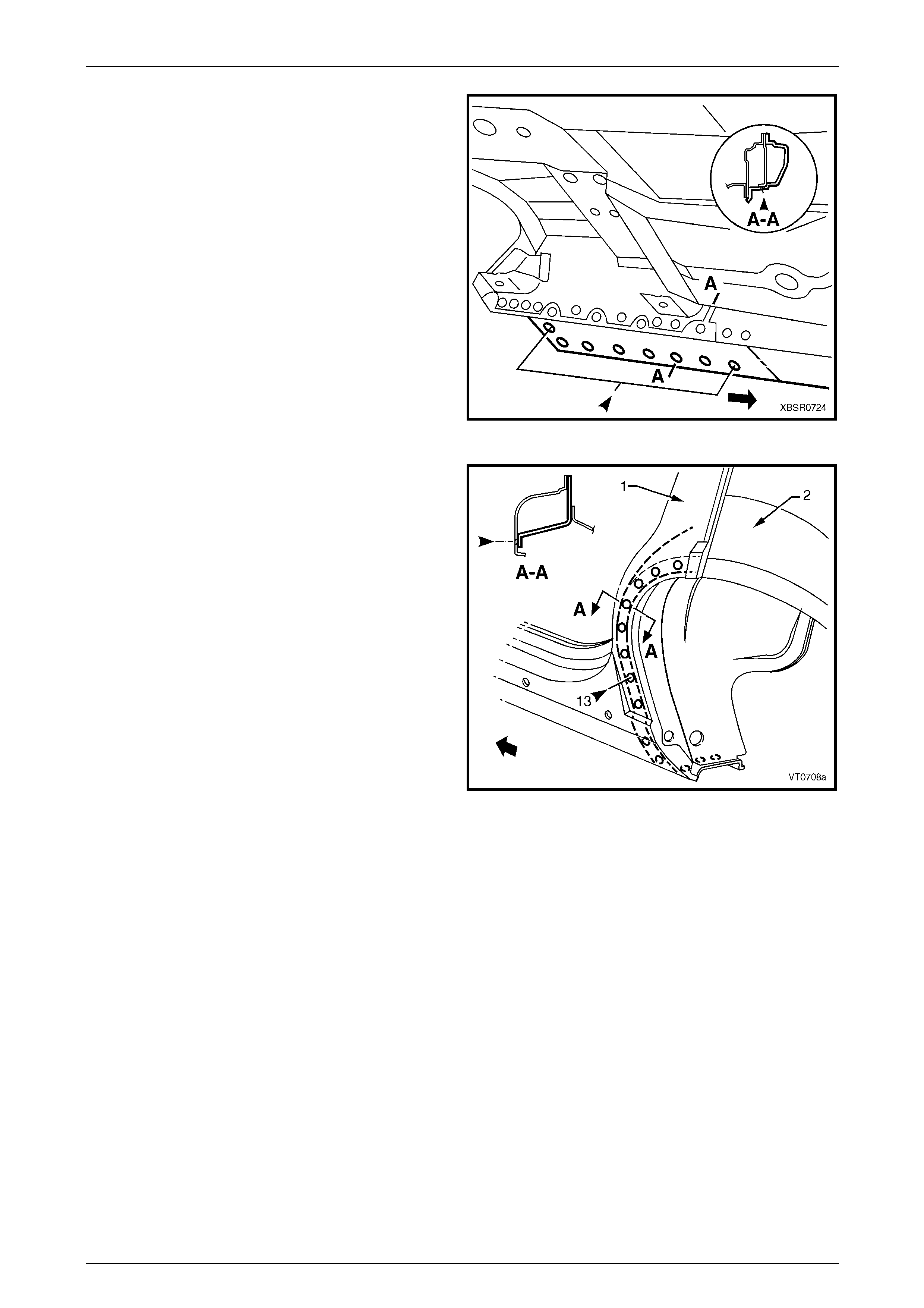
5 Spot cut the welds attaching the underbod y jacking
locator (1) and remove.
6 Spot cut the welds on the flange attaching the centre
pillar section to the inner rocker panel (6).
Refer to weld group A.
7 Spot cut the welds on the underside of the rocker
panel attaching the centre pillar section to the quarter
panel inner assembly (7). Refer to weld group B.
Figure 7A – 79
8 Cut the door opening frame a ssembly (1) and centre
pillar reinforcement (2) at the intersection point of the
centre pillar upper reinforcement (3). T he intersection
point can be seen by looking at the side of the flange.
NOTE
Do not cut through the centre pillar inner
reinforcement assembly (4) or quarter panel
inner assembly (5).
Figure 7A – 80
7A Body Side – Sedan Page 7A-38
Page 7A-38
9 Spot cut the welds on the door opening flanges on
both sides of the centre pillar and remove the centre
pillar section from the vehicle.
Figure 7A – 81
10 From the remaining section of centre pillar, carefully
remove enough of the outer skin (1) to expose the
spot welds joining the overlap pin g sections of centre
pillar upper reinforcement (2) and centre pillar
reinforcement (3).
NOTE
Do not cut the centre pillar inner reinforcement
assembly (4) and quarter panel inner assembly
(5).
Figure 7A – 82
7A Body Side – Sedan Page 7A-39
Page 7A-39
11 Spot cut as shown, to remove the remaining tongue
(1) of the centre pillar reinforcement. Leave the holes
drilled in reinforcement to facilitate plug welding the
replacement section.
Figure 7A – 83
Replace
NOTE
• Spot welding is the preferred method for
attaching of panels and should be used
whenever possible. Where the spot welding
equipment available will not access the
required weld position, a plug weld should be
performed.
• The same number and position of spot welds
(or plug welds) should be used when
replacing the panel, as was used during
manufacture, in order to maintain the original
structural strength of the vehicle.
1 Cut the replacement panel through rocker section as
shown. Accurately measure the positio n of cuts to
match the removed panel section.
Figure 7A – 84
2 Cut the replacement panel at the top of the centre
pillar (1).
NOTE
Position the cut above the tongue on the centre
pillar reinforcement, which is visible from the
back of the panel.
3 Adjust the cut on the vehicle side of the outer panel so
that it matches the cut on the replacement section.
Figure 7A – 85
7A Body Side – Sedan Page 7A-40
Page 7A-40
4 On the replacement panel, cut along each side and
bend back the outer panel (3). This will expose the
spot welds attaching the remaining piece of upper
reinforcement (1) to the tongue (2) of the centre pillar
reinforcement.
Figure 7A – 86
5 Spot cut the nine welds and remove the remaining
section of centre pillar upper reinforc ement (1) from
the replacement panel.
Figure 7A – 87
6 Cut two sections from surplus rocker panel pieces, or
manufacture new sections (1), each ap proximately
100 mm in length.
7 Prepare the mating surfaces and treat with Weld
Through Primer (Item 1) as required,
refer to Section 3A Body Construction – Sedan .
8 Clamp these sections firmly behi nd both the cut faces
of rocker panel on the vehicle and spot or plug weld in
place. Perform the welds at a maximum spacing of
35 mm.
9 Mark the new panel with drilling locations in
preparation for plug welding where required. Drill holes
as marked.
10 Prepare all mating surfaces and treat with Weld
Through Primer (Item 1) as required,
refer to Section 3A Body Construction – Sedan .
Figure 7A – 88
7A Body Side – Sedan Page 7A-41
Page 7A-41
11 Install the replacement panel i n position, sliding the
tongue of the centre pillar reinforcement (1) behind the
centre pillar upper reinforcement (2).
NOTE
Manipulate the rocker panel section in position,
inserting the front first, then the rear.
12 Clamp the assembly in place and p lug weld the centre
pillar upper reinforcement to the centre pill ar
reinforcement at the upper join.
13 Plug weld the rocker panel section to the
reinforcement sections.
14 Spot weld along the door openin g flanges on both
sides of the centre pillar.
Figure 7A – 89
15 Fold the outer panel back in position at the top of the
centre pillar. Spot weld along the door flange section
and MIG butt weld the sections together as shown.
16 MIG butt weld the joins in the rocker panel.
Figure 7A – 90

7A Body Side – Sedan Page 7A-42
Page 7A-42
17 Plug weld the flange attaching the centre pil lar section
(1) to the inner rocker panel (2).
Refer to weld group A.
18 Plug weld on the underside of the rocker panel the
centre pillar section to the quarter panel inner
assembly (3). Refer to weld group B.
19 Plug weld the underbody jacking locator (4) in place.
20 Install the door hinges,
refer to Section 8 Doors, Liftgate and Endgat e.
21 Dress the welds by grinding or sanding, ensuring
sufficient material remains to guarantee the strength of
the weld. Finish the area using an appropriate
technique.
22 Refinish and paint panels and other components as
required. Refer to Section 3 Body Construction .
23 Apply Joint Sealer (Item 3) as required.
Refer to Section 3A Body Construction – Sedan.
24 Apply Cavity Wax (Item 8) as required to the inside of
any box sections or areas inaccessible to paint,
refer to Section 3A Body Construction – Sedan .
25 Insert Cavity Foam into the centre pillar as r equired,
refer to Section 2 Precautions.
26 Install the remaining components as described in the
appropriate Section of the MY 2005 VZ Servic e
Information.
Figure 7A – 91
7A Body Side – Sedan Page 7A-43
Page 7A-43
2.7 Door Opening Frame Assembly – Partial
Replace, Lock Pillar
NOTE
Cavity Foam is used within the hinge, centre and
lock pillar cavities. Care is required when
repairing the vehicle in these areas, refer to
Section 2 Precautions prior to beginning any work
for further information.
Remove
1 Remove the adjacent bolt-on panels a nd components
as described in the appropriate Section of th e MY
2005 VZ Service Information.
2 Install the vehicle on a suitab le fixture. As a minimum,
support the appropriate structural sections of the
vehicle on safety stands.
3 Remove the rear window assembly, refer to
Section 1A6 Stationary Windows in the MY 2 005 VZ
Service Information.
4 Remove rear quarter panel,
refer to 2.1 Rear Quarter Panel – Replace.
Figure 7A – 92
5 Select a cut line (1) on the upper region of the lock
pillar within the region specified.
6 Carefully cut through the outer panel of the door
opening frame assembly only.
NOTE
In this area, the lock pillar reinforcement is
attached to the quarter panel inner assembly.
Thus, the outer panel of the door opening frame
assembly can be removed without affecting the
reinforcement.
Figure 7A – 93
7 Select a cutting position on the rocker panel section of
the door opening frame assembly within the region
specified (1). The cut region is between the two
dimples (2). Cut through the outer panel only.
Figure 7A – 94
7A Body Side – Sedan Page 7A-44
Page 7A-44
8 Spot cut the welds on the flange around the rear door
opening, attaching the door open ing frame assembly
to the quarter panel inner assembly. Begin at the cut
through the top of the pillar and continue to the cut
through the rocker panel section.
Figure 7A – 95
9 Spot cut the welds down the side of the rear window
opening, beginning at the point of the cut through the
lock pillar (1).
Figure 7A – 96
10 Spot cut enough of the welds on the flange below the
rocker panel, to detach the door opening frame
assembly from the inner rocker panel.
Figure 7A – 97
7A Body Side – Sedan Page 7A-45
Page 7A-45
11 Spot cut enough of the welds below the rocker panel,
to detach the door opening frame assembly from the
quarter panel inner assembly.
Figure 7A – 98
12 Spot cut the welds around the wheelhouse attaching
the lock pillar section (1) to the quarter panel inner
assembly (2).
13 Remove the partial door openi ng frame assembly from
the vehicle, then repair any damage to adjacent parts
as required.
14 Check and rectify the alignme nt of
the body as requir ed,
refer to Section 3A Body Construction – Sedan .
Figure 7A – 99
7A Body Side – Sedan Page 7A-46
Page 7A-46
Replace
NOTE
• Spot welding is the preferred method for
attaching of panels and should be used
whenever possible. Where the spot welding
equipment available will not access the
required weld position, a plug weld should be
performed.
• The same number and position of spot welds
(or plug welds) should be used when
replacing the panel, as was used during
manufacture, in order to maintain the original
structural strength of the vehicle.
1 Cut a replacement section from a new door opening frame assembly, accurately measuring the position of cuts to
match the removed section.
2 Manufacture a reinforcement ( 1), appro x. 100 mm in
length to match the inside of the lock pillar section at
the cut.
3 Prepare the mating surfaces and treat with Weld
Through Primer (Item 1) as required,
refer to Section 3A Body Construction – Sedan .
4 Clamp the section firmly behind the cut face of the lock
pillar on the vehicle and spot or plug weld at a
maximum spacing of 35 mm.
Figure 7A – 100
5 Using the same technique, manufactur e or cut a
section of reinforcement panel (1), approx. 100 mm
long, to fit the inside of the existing rocker panel at the
point of the cut.
6 Prepare the mating surfaces and treat with Weld
Through Primer (Item 1) as required,
refer to Section 3A Body Construction – Sedan .
7 Clamp the manufactured reinforcement panel firmly to
the inside of the rocker panel on the ve hicle and plug
weld in position. Position welds at a maximum spacing
of 35 mm.
8 Mark the new lock pillar panel with drilling locations in
preparation for plug welding. Drill holes as required.
9 Prepare all mating surfaces and treat with Weld
Through Primer (Item 1) as required,
refer to Section 3A Body Construction – Sedan .
Figure 7A – 101
7A Body Side – Sedan Page 7A-47
Page 7A-47
10 Clamp the new lock pillar section in place on the
vehicle and check the door opening dimensions,
refer to Section 3A Body Construction – Sedan .
11 Plug weld the replacement panel to the ma nufactured
reinforcement sections in the rocker panel area and at
the top of the pillar.
12 MIG butt weld the joins in both these areas.
Figure 7A – 102
13 Spot weld along the flange around the rear door
opening, attaching the replacement section to the
quarter panel inner assembly.
Figure 7A – 103
14 Spot weld down the side of the rear window opening,
attaching the replacement section to the quarter panel
inner assembly.
Figure 7A – 104
7A Body Side – Sedan Page 7A-48
Page 7A-48
15 Spot weld the flange below the rocker panel, attaching
the replacement section to the inner rocker pan el.
Figure 7A – 105
16 Spot weld below the rocker panel, attaching the
replacement section to the quater panel inn er
assembly.
Figure 7A – 106
17 Spot weld around the wheelhouse to attach the
replacement section to the (1) to the quarter panel
inner assembly (2).
18 Replace rear quarter panel,
refer to 2.1 Rear Quarter Panel – Replace.
19 Refinish and paint panels and other components as
required. Refer to Section 3 Body Construction .
20 Apply Joint Sealer (Item 3) as required.
Refer to Section 3A Body Construction – Sedan.
21 Apply Cavity Wax (Item 8) as required to the inside of
any box sections or areas inaccessible to paint,
refer to Section 3A Body Construction – Sedan .
22 Insert Cavity Foam into the lock pillar as required,
refer to Section 2 Precautions.
23 Install the remaining components as described in the
appropriate Section of the MY 2005 VZ Servic e
Information. Figure 7A – 107
7A Body Side – Sedan Page 7A-49
Page 7A-49
2.8 Door Opening Frame Assembly – Partial
Replace, Rocker Panel
This procedure details the replacement of the
rocker panel section of the door opening
frame assembly.
As there are several critical reinforcements in
the lower hinge pillar area, the rocker panel
section must not be cut forward of the area
shown. If the rocker panel is damaged
forward of this area, replace the rocker panel
and partial hinge pillar as one section. Modify
this procedure accordingly, also referring to
2.5 Door Opening Frame Assembly – Partial
Replace, Hinge Pillar.
Remove
1 Remove the adjacent bolt-on panels a nd components
as described in the appropriate Section of th e MY
2005 VZ Service Information.
2 Remove the rear quarter panel,
refer to 2.1 Rear Quarter Panel – Replace.
3 Secure the vehicle on a suitable fixture. As a
minimum, support the appropriate structural s ections
of the vehicle on safety stands. Install suitable bracing
in the vehicle to ensure that the correct body
alignment is maintained when the rocker panel section
is removed.
Figure 7A – 108
4 Cut through the rocker panel section of the door
opening frame assembly. The cut point (1) must not be
further forward than the third rocker panel m oulding
attaching hole (2). Cut through both the outer panel
and the reinforcement.
Figure 7A – 109
7A Body Side – Sedan Page 7A-50
Page 7A-50
5 Using a suitable cutting tool, cut through the centre
pillar at a position 30 mm below the lower edge of the
door hinge. Cut through both the door opening frame
assembly (1) and centre pillar reinforcement (2).
Figure 7A – 110
6 Cut through the lock pillar at a poi nt between 120 –
220 mm above the top of the rocker panel.
NOTE
There is no reinforcement panel in this area of
the vehicle.
Figure 7A – 111
7 Spot cut the required number of welds, depending on
where the cut is made, to detach the rocker panel
section of the door opening frame assembly (1) from
the quarter panel inner assembl y (2).
8 Spot cut along the flange below the rocker panel as
required, to separate the rocker panel section from the
inner rocker panel and quarter panel inner assembly.
Refer to Figure 7A – 113.
Figure 7A – 112
7A Body Side – Sedan Page 7A-51
Page 7A-51
Figure 7A – 113
9 Spot cut the welds attaching the rocker panel section to the quarter p an el inner assembly as required.
Refer to Figure 7A – 114.
Figure 7A – 114
10 Spot cut the welds along the lower edge of the front
and rear door openings as required, to complete the
detachment of the rocker panel section.
11 Remove the panel from the vehicle, then repair any
damage to adjacent parts.
12 Check and rectify the alignme nt of
the body as requir ed,
refer to Section 3A Body Construction – Sedan .
Figure 7A – 115
7A Body Side – Sedan Page 7A-52
Page 7A-52
Replace
NOTE
• Spot welding is the preferred method for
attaching of panels and should be used
whenever possible. Where the spot welding
equipment available will not access the
required weld position, a plug weld should be
performed.
• The same number and position of spot welds
(or plug welds) should be used when
replacing the panel, as was used during
manufacture, in order to maintain the original
structural strength of the vehicle.
• Cut a new replacement rocker panel section.
Accurately measure the position of the cuts
on the removed section.
1 Remove a section of inner rocker panel (1), cut 50 mm
each side of the cut in the rocker panel. This allows
access for welding the rocker panel reinf orcement.
Figure 7A – 116
2 Manufacture or cut a reinforcement (1) (appr oximately
100 mm long) to fit on the inside of the existing rocker
panel at the point of the cut.
3 Prepare the mating surfaces and treat with Weld
Through Primer (Item 1) as required,
refer to Section 3A Body Construction – Sedan .
4 Clamp the manufactured reinforcement firmly to the
inside of the rocker panel section of the d oor opening
frame assembly on the vehicle and plug weld in
position. Position welds at a maximum sp acing of
35 mm.
Figure 7A – 117
7A Body Side – Sedan Page 7A-53
Page 7A-53
5 Manufacture or cut a reinforcement (1) (appr oximately
100 mm long) to fit inside of the existing centre pillar
section at the point of the cut.
6 Prepare the mating surfaces and treat with Weld
Through Primer (Item 1) as required,
refer to Section 3A Body Construction – Sedan .
7 Clamp the manufactured reinforcement panel firmly to
the inside of the outer panel of the door opening frame
assembly on the vehicle and p lug weld in position.
Position welds at a maximum spacing of 35 mm.
8 Repeat steps 6, 7 and 8 and install a reinforcement at
the rear rocker panel / lock pillar lower cut as required.
9 Mark the replacement rocker panel section with drilling
positions in preparation for plug welding as required.
Figure 7A – 118
NOTE
The outer panel will be plug welded from the
outer side of the vehicle, while the rocker panel
and centre pillar reinforcements will be butt
welded from the inner side of the vehicle.
10 Prepare all mating surfaces and treat with Weld Through Primer (Item 1) as required,
refer to Section 3A Body Construction – Sedan .
11 Install the replacement section onto the vehicle by sliding the front and centre pillar sections onto the
reinforcements, while lifting the rear into posi tion.
12 Clamp the panel in position.
13 Weld the new section to the centre pillar by plug
welding (1).
14 MIG butt weld the centre pillar reinforcement from
inside the centre pillar, through the large ho le in the
inner panel immediately behind the weld.
15 Finish the centre pillar attachment by MIG welding (2)
along the join of the outer panel.
Figure 7A – 119
7A Body Side – Sedan Page 7A-54
Page 7A-54
16 Plug weld (1) the replacement section at the front join,
then MIG butt weld (2) the two sections together.
Figure 7A – 120
17 Gaining access through the section of removed floor
side panel, MIG butt weld (1) the new section of rocker
panel reinforcement to the existing section.
18 Replace the removed section of floor side panel (2) by
MIG butt welding it in place and spot welding it along
the door opening flange. Repl ace the spot welds with
the same number as were removed.
Figure 7A – 121
19 Plug weld the rear join as required.
20 MIG butt weld the joint line between the panels.
Figure 7A – 122
7A Body Side – Sedan Page 7A-55
Page 7A-55
21 Spot or plug weld the flanges of the front and rear door
openings as required.
NOTE
Use the same number and position of welds as
removed during removal.
22 Spot or plug weld the door opening frame al ong the
flange below the rocker panel as required,
refer to Figure 7A – 124.
Figure 7A – 123
Figure 7A – 124
7A Body Side – Sedan Page 7A-56
Page 7A-56
23 Plug weld up through the rocker panel to attach the replacement section to the quarter panel inner assembly.
Refer to Figure 7A – 125.
Figure 7A – 125
24 If required, spot weld the replacement section to the
quarter panel inner assembly around the rear wheel
arch as shown.
25 Refinish and paint panels and other components as
required. Refer to Section 3 Body Construction .
26 Apply Joint Sealer (Item 3) as required.
Refer to Section 3A Body Construction – Sedan.
27 Apply Cavity Wax (Item 8) as required to the inside of
any box sections or areas inaccessible to paint,
refer to Section 3A Body Construction – Sedan .
28 Install the remaining components as described in the
appropriate Section of the MY 2005 VZ Servic e
Information.
Figure 7A – 126
7A Body Side – Sedan Page 7A-57
Page 7A-57
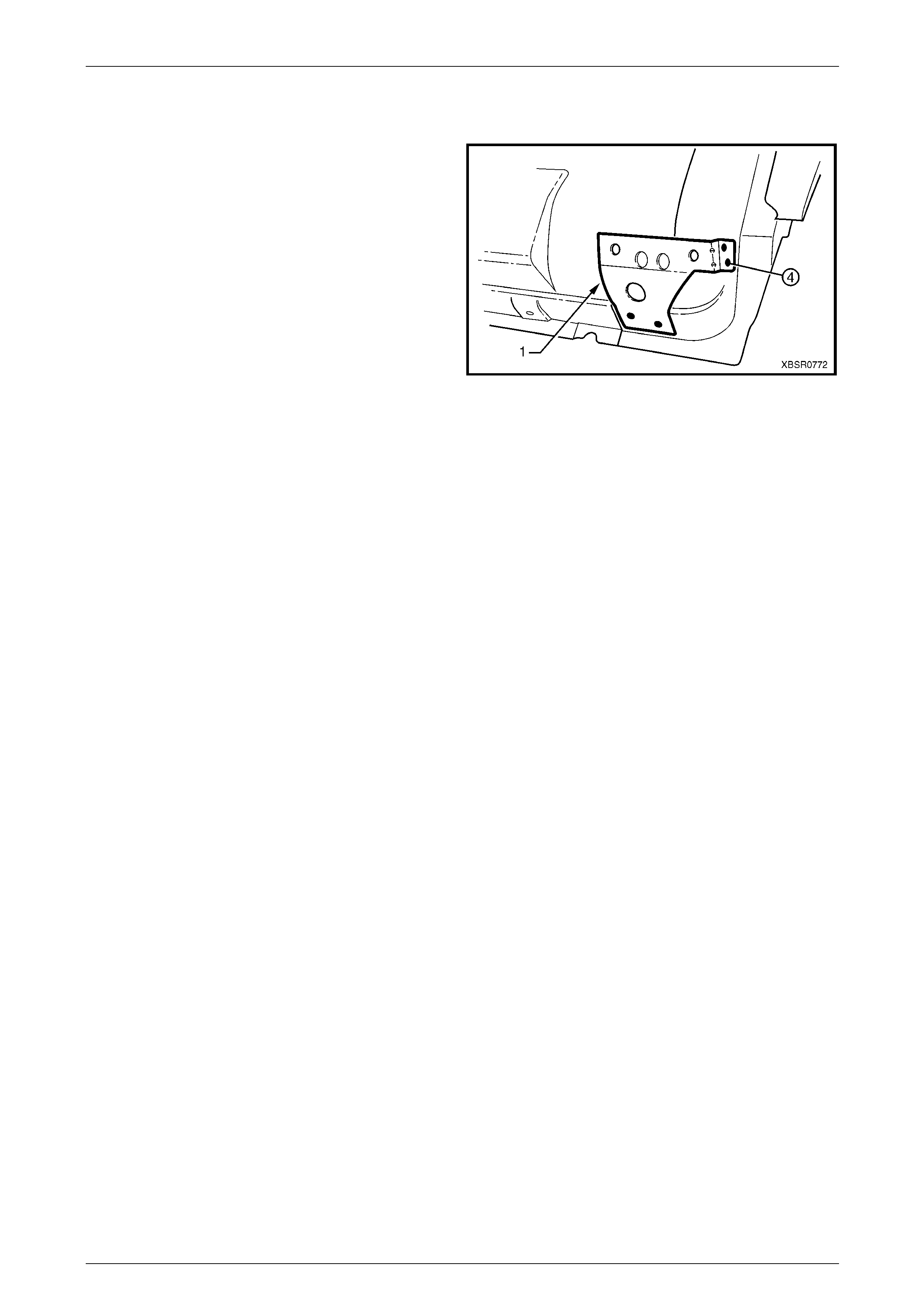
2.9 Fender Lower Rear Bracket – Replace
The fender lower rear bracket (1) is spot welded at four
places to the door opening fra m e assembly.
Clamp the fender lower rear bracket positi on as shown prior
to plug welding and check the alig nment of the fender to the
body and front door.
Refinish and paint panels and other components as
required. Refer to Section 3 Body Construction .
Apply Cavity Wax (Item 8) as r equired to the inside of any
box sections or areas inaccessible to paint,
refer to Section 3A Body Construction – Sedan .
Figure 7A – 127
7A Body Side – Sedan Page 7A-58
Page 7A-58
2.10 Hinge Pillar Inner Panel Assembly –
Replace
Remove
1 Remove the adjacent bolt-on panels a nd components
as described in the appropriate Section of th e MY
2005 VZ Service Information.
2 Remove the door opening frame assembly, refer to
2.4 Door Opening Frame Assembly – Repl ace, or
remove the hinge pillar section of the door opening
frame assembly, refer to 2.5 Door Opening Frame
Assembly – Partial Replace, Hinge Pil lar .
3 If required, remove the dash panel assembl y,
refer to Section 5 Cockpit Module in this Supplement.
NOTE
If the cockpit module is not damaged an
alternative is provided in this p rocedure.
4 Add bracing as requir ed to maintain the alignment of
the vehicle structure.
Figure 7A – 128
5 Grind the MIG welds (1) attaching the hinge pill ar inner
panel assembly to the inner rocker panel.
Figure 7A – 129
6 Spot cut the welds attaching the hinge pillar i nner
panel assembly to the roof front header and quarter
panel inner extension.
NOTE
Structural adhesive is applied to join (1). If the
roof panel has not been removed, it will be very
difficult to remove the panel. As an alternative:
• If only the lower section is damaged, detach
the hinge pillar inner upper panel (1) from the
hinge pillar inner lo wer panel (2) and replac e
the lower panel, or
• Cut the hinge pillar inner panel assembly (3)
approximately 50 mm from the top
of the windscreen aperture. If a partial
replacement of the door opening frame
assembly is being performed, this point is
50 mm above the cut in the outer panels (4).
Refer to Figure 7A – 131.
Figure 7A – 130
7A Body Side – Sedan Page 7A-59
Page 7A-59
Figure 7A – 131
7 Spot cut the welds attaching the hinge pillar i nner
panel assembly to the front wheelhouse panel and
front floor panel extension, refer to weld group A.
8 If the dash panel assembly was not removed, spot cut
the eight welds attaching the adhesive channels to the
hinge pillar inner panel assembly, refer to weld group
B.
9 If required, remove any remainin g spot welds where
the wheelhouse panel upper side rail attached the
front wheelhouse panel a nd hinge pillar inner panel
assembly.
10 Cut the adhesive between the dash panel assembl y
and hinge pillar inner panel assembly.
11 Remove the hinge pillar in ner panel assembly from the
vehicle and as required, cle an off any remaining
adhesive and ensure the adhesive channels are
removed.
12 Repair any damage to adjacent parts as required. Figure 7A – 132

7A Body Side – Sedan Page 7A-60
Page 7A-60
Replace
NOTE
• Spot welding is the preferred method for
attaching of panels and should be used
whenever possible. Where the spot welding
equipment available will not access the
required weld position, a plug weld should be
performed.
• The same number and position of spot welds
(or plug welds) should be used when
replacing the panel, as was used during
manufacture, in order to maintain the original
structural strength of the vehicle.
1 If an alternate removal method was used, referring to Figure 7A – 131, either:
• Cut the replacement section to match the cut at the top of the hinge pill ar, or
• Spot cut the welds attaching the hinge pillar i nner upper panel to the hinge pillar inner lower panel.
2 Mark the new panel and drill holes in preparation for plug welding where required.
3 Prepare all mating surfaces and treat with Weld Through Primer (Item 1) as required,
refer to Section 3A Body Construction – Sedan .
4 If the dash panel assembly was removed, it will be installed later, proceed to Step 7.
5 If the dash panel assembly was not removed, prepare the adh esive channels on the replacement section and the
dash panel assembly, refer to Section 5 Cockpit Modu le .
6 Mix the dash panel silic one adhesive refer to Section 5 Cockpit Module . Apply the a dh esive to fill the adhesive
channels on the replaceme nt section.
NOTE
Only the correct material described in
Section 5 Cockpit Module is to be used.
7 If the full hinge pillar inner panel assembly is being replaced, apply structural adhesive (Item 6) to the mating
surfaces of the hinge pillar inner panel as sembly and quarter panel inner extension,
refer to Section 3A Body Construction – Sedan .
7A Body Side – Sedan Page 7A-61
Page 7A-61
8 Install and clamp the new panel in position on the
vehicle.
NOTE
If the dash panel assembly was not removed,
place the hinge pillar inner panel assembly (1)
slightly lower and slide it upwards ensuring the
dash panel flange (2) seats into the adhesive
channel.
9 Temporarily install the dash p anel attaching bolts
through the hinge pillar i nn er panel assembly and
within the plenum chamber.
10 Finish the application of the dash panel adhesive,
refer to Section 5 Cockpit Module .
Figure 7A – 133
11 If the full hinge pillar inner panel assembly was
removed, spot or plug weld the hinge pillar inner panel
assembly to the roof front header and quarter pane l
inner extension.
NOTE
Ensure the structural adhesive Item 6, is applie d
to the join (1) refer to Section 3A Body
Construction – Sedan
12 If only the lower section was removed, spot or plug
weld the hinge pillar inner upper panel (1) to the hinge
pillar inner lower panel (2), refer to Figure 7A – 135.
13 If the pillar was cut near the top of the windscreen
aperture, either MIG butt weld the join (3) if the full
door opening frame assembly was remov ed, or make
two tack welds to secure it until the door opening
frame assembly hinge pillar s ection is installed, also
refer to Figure 7A – 135.
Figure 7A – 134
NOTE
This join forms the top access cut point for joining
of the reinforcement as described in 2.5 Door
Opening Frame Assembly – Partial Replace,
Hinge Pillar.
7A Body Side – Sedan Page 7A-62
Page 7A-62
Figure 7A – 135
14 Spot or plug weld the hinge pillar in ner panel assembly
to the front wheelhouse panel and front floor
extension.
Figure 7A – 136
15 MIG weld two places (1) across the inner rocker panel
and hinge pillar inner panel assembly.
16 Replace the door opening fra me assembly, refer to
2.4 Door Opening Frame Assembly – Repl ace or the
hinge pillar section of the door opening frame
assembly, refer to 2.5 Door Opening Frame Assembly
– Partial Replace, Hinge Pill ar.
17 Refinish and paint panels and other components as
required. Refer to Section 3 Body Construction .
18 Apply Joint Sealer (Item 3) as required.
Refer to Section 3A Body Construction – Sedan.
19 Apply Cavity Wax (Item 8) as required to the inside of
any box sections or areas inaccessible to paint,
refer to Section 3A Body Construction – Sedan .
20 Install the remaining components as described in the
appropriate Section of the MY 2005 VZ Servic e
Information.
Figure 7A – 137
7A Body Side – Sedan Page 7A-63
Page 7A-63
2.11 Quarter Panel Inner Assembly – Replace
Remove
1 Remove the adjacent bolt-on panels a nd components
as described in the appropriate Section of th e MY
2005 VZ Service Information.
2 Mount the vehicle on a suitable jig to mai ntai n correct
body alignment when the quarter panel inner
assembly is removed.
3 Remove rear quarter panel,
refer to 2.1 Rear Quarter Panel – Replace.
4 Remove the roof panel, and partially remove the
roof bow panel and roof rear panel,
refer to Section 9A Roof.
5 Remove the door opening frame assembly, refer to
2.4 Door Opening Frame Assembly – Repl ace.
6 Add further bracing tools as required, to maintain the
alignment of the vehicle structure.
Figure 7A – 138
7 Cut any remaining spot welds and grind the MIG welds
(1), attaching the quarter panel in ner assembly to the
inner rocker panel.
8 Spot cut the welds attaching the rear wheelhouse
inner to the rear floor panel assembly,
refer to Figure 7A – 140.
Figure 7A – 139
Figure 7A – 140
7A Body Side – Sedan Page 7A-64
Page 7A-64
9 Spot cut the welds attaching the rear windo w panel
assembly (1) to the rear seat back extension assembly
(2).
Figure 7A – 141
10 As required, spot cut the welds attaching the rear seat
back extension assembly (1) t o the rear window panel
assembly (2).
NOTE
• Structural adhesive (Item 6) is applied in the
areas shown shaded. As this material is
extremely strong, the rear seat back
extension assembly may require removing
with a grinder.
• Remove the remaining flange of the rear
quarter panel, leaving only the rear window
panel assembly.
Figure 7A – 142
11 The quarter panel inner extension (1) is attached to
the hinge pillar inner panel assembly with spot welds
and structural adhesive (2) (Item 6, refer to
Section 3A Body Construction – Sedan). As the
adhesive is extremely strong, cut through the quarter
panel inner extension just behind the join and remove
the remaining joint piece with a grinder.
NOTE
As an alternative, remove the spot welds from
the join (3), leaving the quarter panel inner
extension intac t.
12 Remove the quarter panel inner assembly from the
vehicle, then repair any damage to adjacent parts as
required.
13 Check and rectify the alignme nt of
the body as requir ed,
refer to Section 3A Body Construction – Sedan .
Figure 7A – 143
7A Body Side – Sedan Page 7A-65
Page 7A-65
Replace
NOTE
• Spot welding is the preferred method for
attaching of panels and should be used
whenever possible. Where the spot welding
equipment available will not access the
required weld position, a plug weld should be
performed.
• The same number and position of spot welds
(or plug welds) should be used when
replacing the panel, as was used during
manufacture, in order to maintain the original
structural strength of the vehicle.
1 Mark the new panel and drill holes in preparation for plug welding where required.
2 Prepare all mating surfaces and treat with Weld Through Primer (Item 1) as required,
refer to Section 3A Body Construction – Sedan .
3 Either, apply structural adhesive (Item 6,
refer to Section 3A Body Construction – Sedan ) to the
mating surfaces of the quarter panel inner extension
and hinge pillar inner p an el assembly (1), if this joint
was cut or, remove the quarter panel inner extension
from the replacement section.
4 Clamp the new panel in position on the vehicle.
5 Depending on removal method either:
• Spot weld the quarter panel inner extension and
hinge pillar inner panel assembly join (1), or
• Spot weld the quarter panel inner ass embl y to
the quarter panel inner extension (2). Figure 7A – 144
6 Spot weld the quarter panel inner ass embl y to the
inner rocker panel.
NOTE
Only make several spot welds in the door
opening flanges as they will be fully welded
when the door opening frame assembly is fitted.
7 MIG weld the base of the centre pillar (1) and the
series of three MIG welds at the base of the lock pillar.
NOTE
Each MIG weld to be 25 mm long.
Figure 7A – 145

7A Body Side – Sedan Page 7A-66
Page 7A-66
8 Plug weld the rear window panel assembly (1) to the
rear seat back extension assembly (2).
9 Spot weld the rear wheelhouse inner (1) to the rear
floor panel assembly, refer to Figure 7A – 14 7.
Figure 7A – 146
Figure 7A – 147
10 Clean up welds as required and prime any bare metal.
11 Install the door opening frame assembly, refer to 2.4 Door Opening Frame Assembly – Replace.
12 Replace the roof and roof support panels, as described in Section 9A Roof in this Supplement.
13 Prepare the rear quarter panel for installatio n, refer to 2.1 Rear Quarter Panel – Replace.
Do not modify the rear quarter panel flange at
the base of the lock pillar as stated in the rear
quarter panel replacement procedure, as the
flange is required for this procedure.

7A Body Side – Sedan Page 7A-67
Page 7A-67
14 Using a lever, gently prise d own the rear seat back
extension asse mbly sufficiently to allo w structural
adhesive (Item 6, refer to Section 3A Body
Construction – Sedan) to be inserted into th e mating
flange as shown (2).
Figure 7A – 148
15 Apply structural adhesive (Item 6, refer to
Section 3A Body Construction – Sedan) to the rear
quarter panel flange as shown (1).
16 Fit and clamp the rear quarter panel into position,
refer to 2.1 Rear Quarter Panel – Replace.
NOTE
Ensure the rear quarter panel flange (1) is fitted
between the quarter panel inner assembly and
rear window panel ass embly. If required pr ise up
the rear window panel to provide clearance.
Figure 7A – 149
17 Spot or plug weld through the rear window panel
assembly (1), rear seat back extension assembly (2)
and rear quarter panel (3) as shown.
18 Finish installing the rear quar ter panel,
refer to 2.1 Rear Quarter Panel – Replace.
19 Refinish and paint panels and other components as
required. Refer to Section 3 Body Construction .
20 Apply Joint Sealer (Item 3) as required.
Refer to Section 3A Body Construction – Sedan.
21 Apply Cavity Wax (Item 8) as required to the inside of
any box sections or areas inaccessible to paint,
refer to Section 3A Body Construction – Sedan .
22 Apply spray-on deadener to the
wheel side of the wheelhouse,
refer to Section 3A Body Construction – Sedan .
23 Install the remaining components as described in the
appropriate Section of the MY 2005 VZ Servic e
Information.
Figure 7A – 150
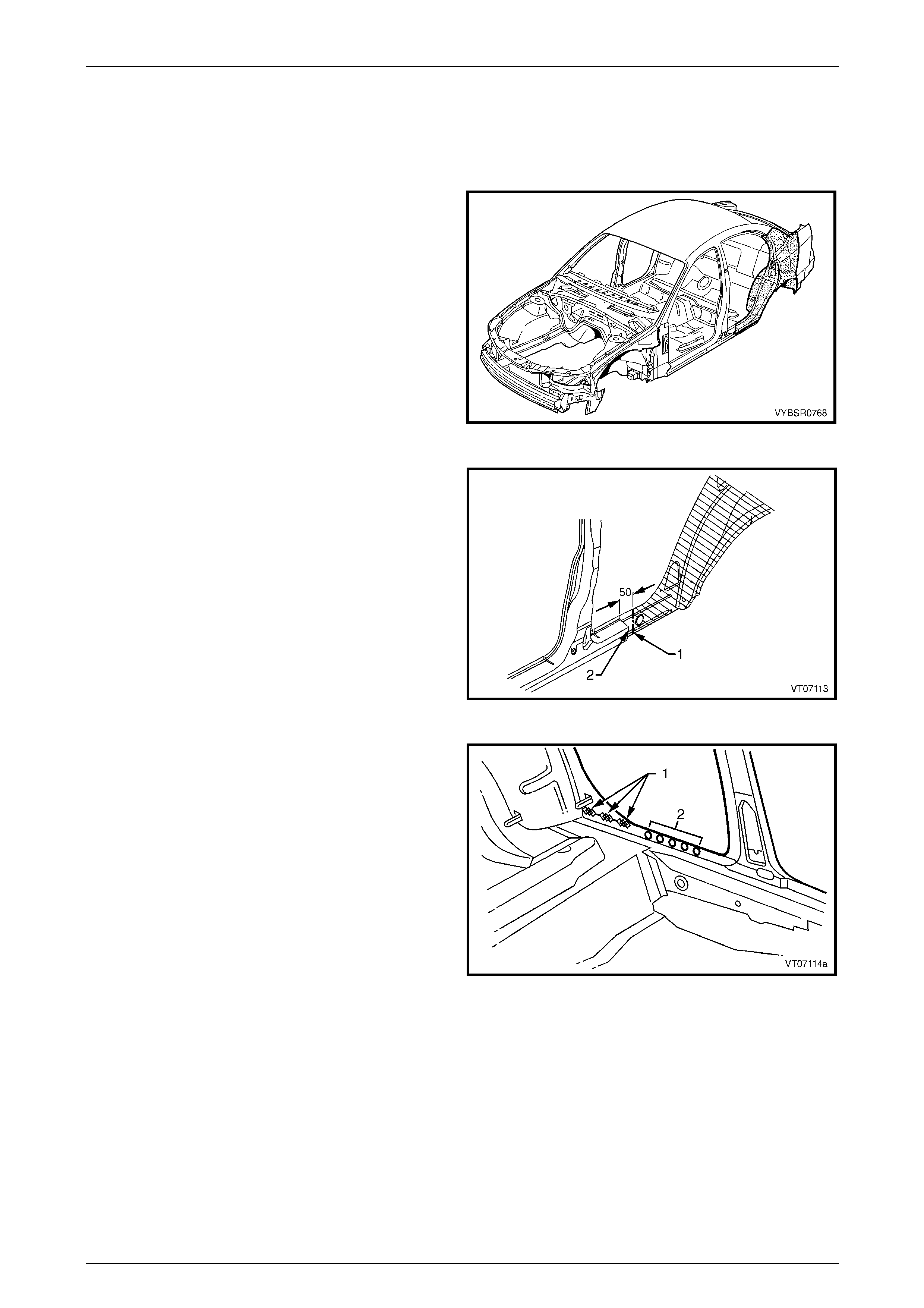
7A Body Side – Sedan Page 7A-68
Page 7A-68
2.12 Quarter Panel Inner Assembly – Partial
Replace
Remove
1 Remove the adjacent bolt-on panels a nd components
as described in the appropriate Section of th e MY
2005 VZ Service Information.
2 If required, mount the vehicle on a suitable fixture.
Secure a suitable tool bet ween the rear door opening
flanges to maintain alignment once the sections are
removed.
3 Remove rear quarter panel,
refer to 2.1 Rear Quarter Panel – Replace.
4 Remove lock pillar section of the door opening frame
assembly, refer to 2.7 Door Opening Frame Assembly
– Partial Replace, Lock Pillar.
Figure 7A – 151
5 Carefully cut through the quarter panel inner assembly
at the rocker panel region.
NOTE
The position of the cut (1) should be a minimum
of 50 mm short er than that of the outer panel (2)
to allow sufficient access for rejoining.
Figure 7A – 152
6 Grind off the MIG welds (1) and cut enough spot welds
(2) to detach the quarter panel inner assembly section
from the inner rocker panel.
7 Spot cut the welds attaching the rear wheelhouse
inner (1) to the rear floor panel assembly,
refer to Figure 7A – 154.
Figure 7A – 153
7A Body Side – Sedan Page 7A-69
Page 7A-69
Figure 7A – 154
8 Spot cut the welds attaching the rear windo w panel
assembly (1) to the rear seat back extension assembly
(2).
Figure 7A – 155
9 As required, spot cut the welds attaching the rear seat
back extension assembly (1) t o the rear window panel
assembly (2).
NOTE
• Structural adhesive (Item 6) is applied in the
areas shown shaded. As this material is
extremely strong, the rear seat back
extension assembly may require removing
with a grinder.
• Remove the remaining flange of the rear
quarter panel, leaving only the rear window
panel assembly.
Figure 7A – 156

7A Body Side – Sedan Page 7A-70
Page 7A-70
10 Cut through the lock pillar reinforcement panel (1) and
quarter panel inner assembly at a point 5 0 mm below
the cut through the lock pillar section of the door
opening frame assembly (2).
11 Remove the partial quarter panel inner assembly from
the vehicle, then repair any damage to adjacent parts.
12 Check and rectify the alignme nt of
the body as requir ed,
refer to Section 3A Body Construction – Sedan .
Figure 7A – 157
Replace
NOTE
• Spot welding is the preferred method for
attaching of panels and should be used
whenever possible. Where the spot welding
equipment available will not access the
required weld position, a plug weld should be
performed.
• The same number and position of spot welds
(or plug welds) should be used when
replacing the panel, as was used during
manufacture, in order to maintain the original
structural strength of the vehicle.
1 Accurately cut a replacement inner lock pillar section from a new panel assembly. The new panel should be cut
40 mm longer at the mating faces to allo w for overlap.
2 Remove the flange from the overlap section and form
a joggle (1) at the top end of the ne w panel to facilitate
a lap joint. Both the inner pan el an d reinforcement
panel should be joggle d.
NOTE
Accurately measure the requ ired length of joggle
to match the overlap. This should be slightly in
excess of 40 mm.
Figure 7A – 158
7A Body Side – Sedan Page 7A-71
Page 7A-71
3 Remove the flange from the overlap area and form a
joggle (1) in the rocker panel area of the ne w pan el to
allow for a lap joint in this area.
NOTE
Accurately measure the requ ired length of joggle
to match the overlap. This should be slightly in
excess of 40 mm.
4 Mark the new panel and the existing panels with
drilling locations in preparation for plug welding where
required. Drill holes as marked.
5 Prepare all mating surfaces and treat with Weld
Through Primer (Item 1) as required,
refer to Section 3A Body Construction – Sedan .
6 Position the new panel on the vehicle and clamp in
place.
Figure 7A – 159
7 Plug weld the lap joints at the top of the lock pillar (1)
and in the rocker panel area (2).
8 Finish the joints by MIG welding (3).
Figure 7A – 160
9 MIG weld (1) in three places (each 25 mm long) and
spot weld (2) as required to attach the qu arter panel
inner assembly to the inner rocker panel.
Figure 7A – 161
7A Body Side – Sedan Page 7A-72
Page 7A-72
10 Plug weld the rear window panel assembly (1) to the
rear seat back extension assembly (2).
11 Spot weld the rear wheelhouse inner (1) to the rear
floor panel assembly, refer to Figure 7A – 16 3.
Figure 7A – 162
Figure 7A – 163
12 Clean up welds as required and prime any bare metal.
13 Replace the partial lock pillar secti on of the door opening frame assembly.
Refer to 2.7 Door Opening Frame Assembly – Partial Replace, Lock Pillar.
14 Prepare the rear quarter panel for installatio n, refer to 2.1 Rear Quarter Panel – Replace.
Do not modify the rear quarter panel flange at
the base of the lock pillar as stated in the rear
quarter panel replacement procedure, as the
flange is required for this procedure.
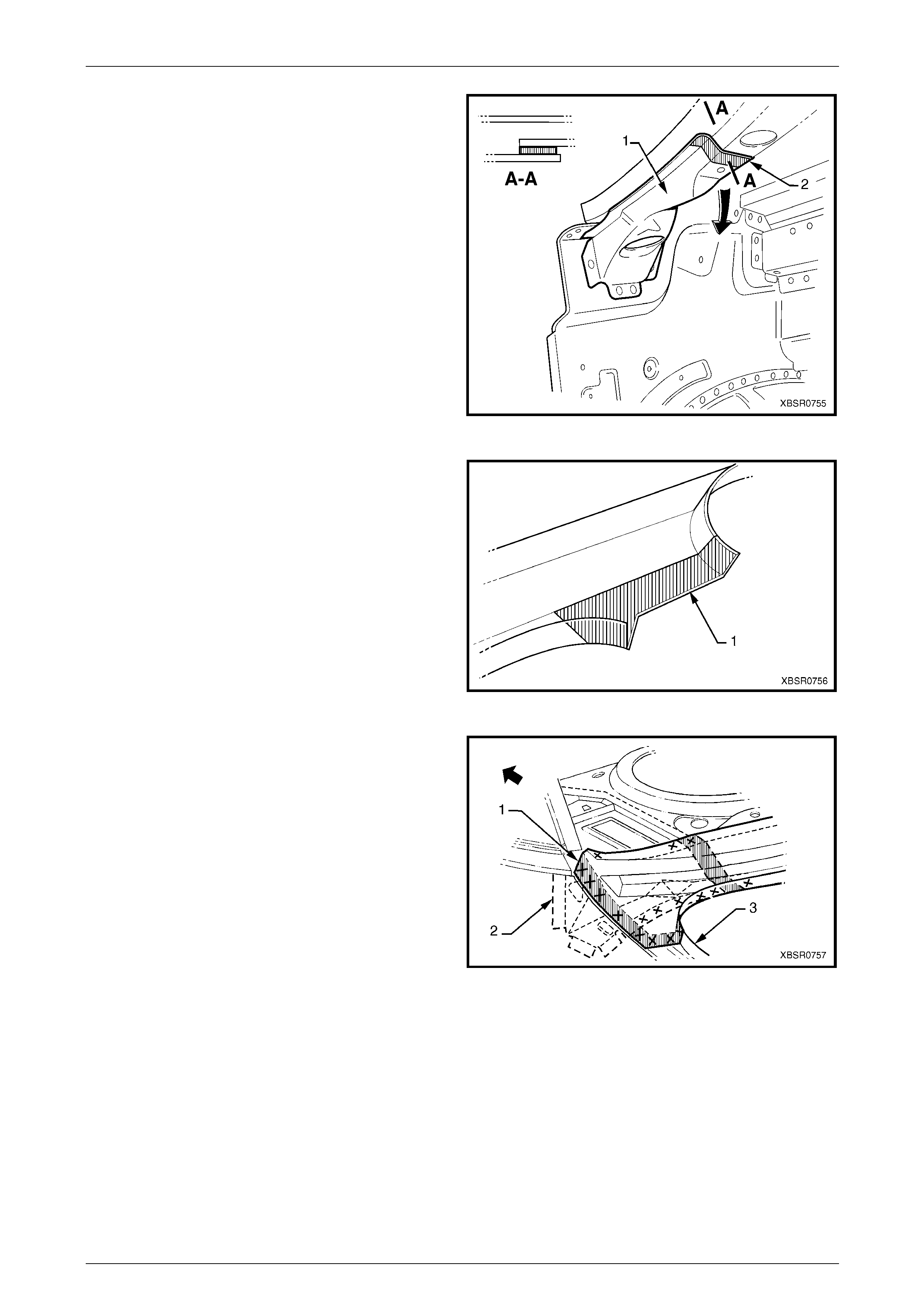
7A Body Side – Sedan Page 7A-73
Page 7A-73
15 Using a lever, gently prise d own the rear seat back
extension asse mbly sufficiently to allo w structural
adhesive (Item 6, refer to Section 3A Body
Construction – Sedan) to be inserted into th e mating
flange as shown (2).
Figure 7A – 164
16 Apply structural adhesive (Item 6, refer to
Section 3A Body Construction – Sedan) to the rear
quarter panel flange as shown (1).
17 Fit and clamp the rear quarter panel into position,
refer to 2.1 Rear Quarter Panel – Replace.
NOTE
Ensure the rear quarter panel flange (1) is fitted
between the quarter panel inner assembly and
rear window panel ass embly. If required pr ise up
the rear window panel to provide clearance.
Figure 7A – 165
18 Spot or plug weld through the rear window panel
assembly (1), rear seat back extension assembly (2)
and rear quarter panel (3) as shown.
19 Finish installing the rear quar ter panel,
refer to 2.1 Rear Quarter Panel – Replace.
20 Refinish and paint panels and other components as
required. Refer to Section 3 Body Construction .
21 Apply Joint Sealer (Item 3) as required.
Refer to Section 3A Body Construction – Sedan.
22 Apply Cavity Wax (Item 8) as required to the inside of
any box sections or areas inaccessible to paint,
refer to Section 3A Body Construction – Sedan .
23 Install the remaining components as described in the
appropriate Section of the MY 2005 VZ Servic e
Information.
Figure 7A – 166