7B Body Side – Wagon Page 7B-1
Page 7B-1
Section 7B
Body Side – Wagon
ATTENTION
Before performing any service operation or other procedure described in this Section, refer to Section 2
Precautions in this Supplement and Section 00 Warnings, Cautions and Notes in the MY2005 VZ Service
Information for correct workshop practices with regard to safety and/or property damage.
The structure of the body shell has been
developed using complex design and
development techniques. In addition to
meeting all required standards, the vehicle
body is also a critical part of the overall safety
systems. It is therefore imperative the repair
procedures described here are adhered to
during all vehicle body repairs.
1 General Description ...............................................................................................................................3
1.1 Body Side Components ........................................................................................................................................ 3
2 Service Operations.................................................................................................................................5
2.1 Rear Quarter Panel – Replace............................................................................................................................... 5
Remove................................................................................................................................................................... 5
Replace................................................................................................................................................................... 7
2.2 Quarter Panel Extension – Replace.................................................................................................................... 10
Remove................................................................................................................................................................. 10
Replace................................................................................................................................................................. 11
2.3 Quarter Panel Inner Lower Rear Extension – Replace ..................................................................................... 12
Remove................................................................................................................................................................. 12
Replace................................................................................................................................................................. 13
2.4 Quarter Outer Lower Rear Panel – Replace....................................................................................................... 14
Remove................................................................................................................................................................. 14
Replace................................................................................................................................................................. 15
2.5 Door Opening Frame Assembly – Replace........................................................................................................ 16
Remove................................................................................................................................................................. 16
Replace................................................................................................................................................................. 21
2.6 Door Opening Frame Assembly – Partial Replace, Hinge Pillar...................................................................... 26
Remove................................................................................................................................................................. 26
Replace................................................................................................................................................................. 29
2.7 Door Opening Frame Assembly – Partial Replace. Centre Pillar..................................................................... 34
Remove................................................................................................................................................................. 34
Replace................................................................................................................................................................. 37

7B Body Side – Wagon Page 7B-2
Page 7B-2
2.8 Door Opening Frame Assembly – Partial Replace, Lock Pillar........................................................................ 41
Remove................................................................................................................................................................. 41
Replace................................................................................................................................................................. 43
2.9 Door Opening Frame Assembly – Partial Replace, Rocker Panel................................................................... 46
Remove................................................................................................................................................................. 46
Replace................................................................................................................................................................. 49
2.10 Fender Lower Rear Bracket – Replace............................................................................................................... 54
2.11 Hinge Pillar Inner Panel Assembly – Replace ................................................................................................... 55
Remove................................................................................................................................................................. 55
Replace................................................................................................................................................................. 56
2.12 Quarter Panel Inner Assembly – Replace.......................................................................................................... 59
Remove................................................................................................................................................................. 59
Replace................................................................................................................................................................. 61
2.13 Quarter Panel Inner Assembly – Partial Replace.............................................................................................. 64
Remove................................................................................................................................................................. 64
Replace................................................................................................................................................................. 67
3 Torque Wrench Specifications............................................................................................................70
7B Body Side – Wagon Page 7B-3
Page 7B-3
1 General Description
This Section describes the replacement procedures for the body side components of the Wagon body structure. Removal
of bolt-on panels and mechanic al components is not covered.
When repairing the body side of the vehicle, care must be taken to ensure the structure is returned to its original
production configuration. This is especially important to maintain side impact standards and for the veh icle’s occupant
protection system to operate correctly.
This Section includes door opening frame assembly partial r eplacement procedures for the hinge pillar, centre pillar, lock
pillar and rocker panel. These procedures must be followed carefull y, as they regularl y involve hidden reinforceme nt
panels. The cutting locations specified are the only plac es allowable.
NOTE
It is imperative the correct body adhesives,
sealers, deadeners and cavity waxes are used
when repairing the body structure. Refer to
Section 3B Body Construction – Wagon.
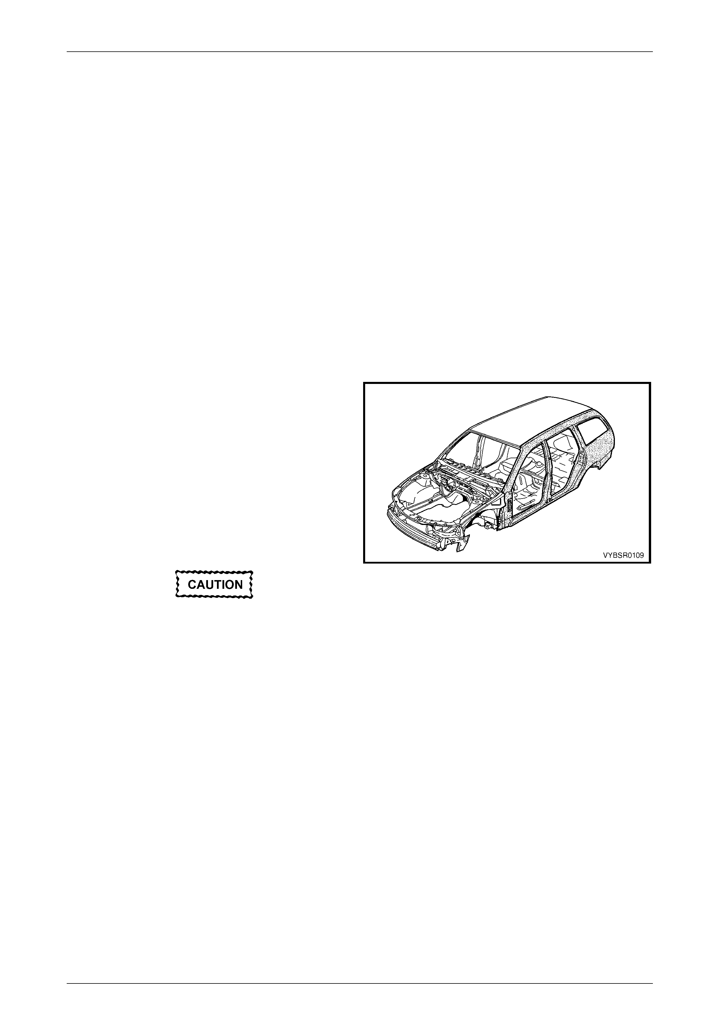
1.1 Body Side Components
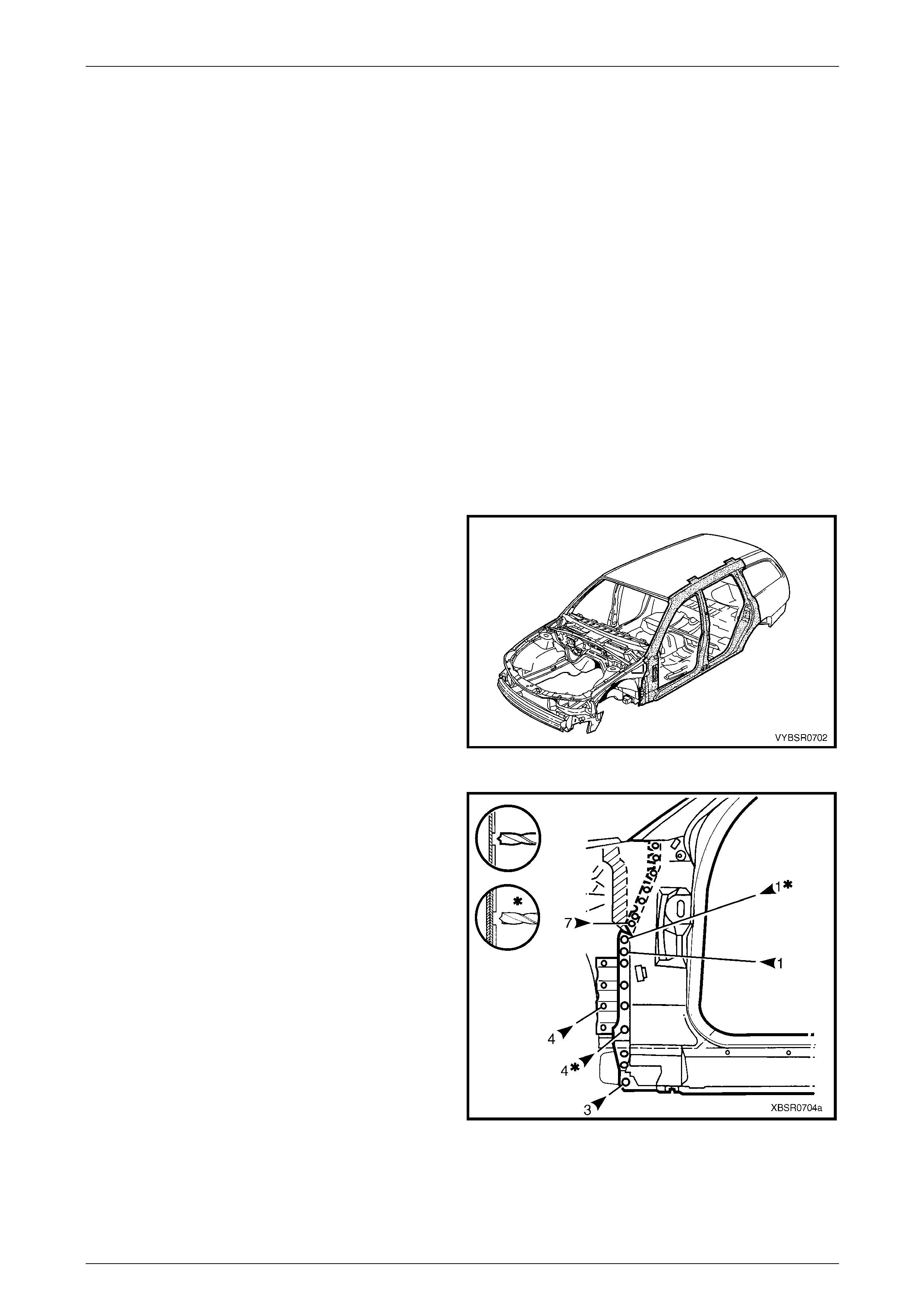
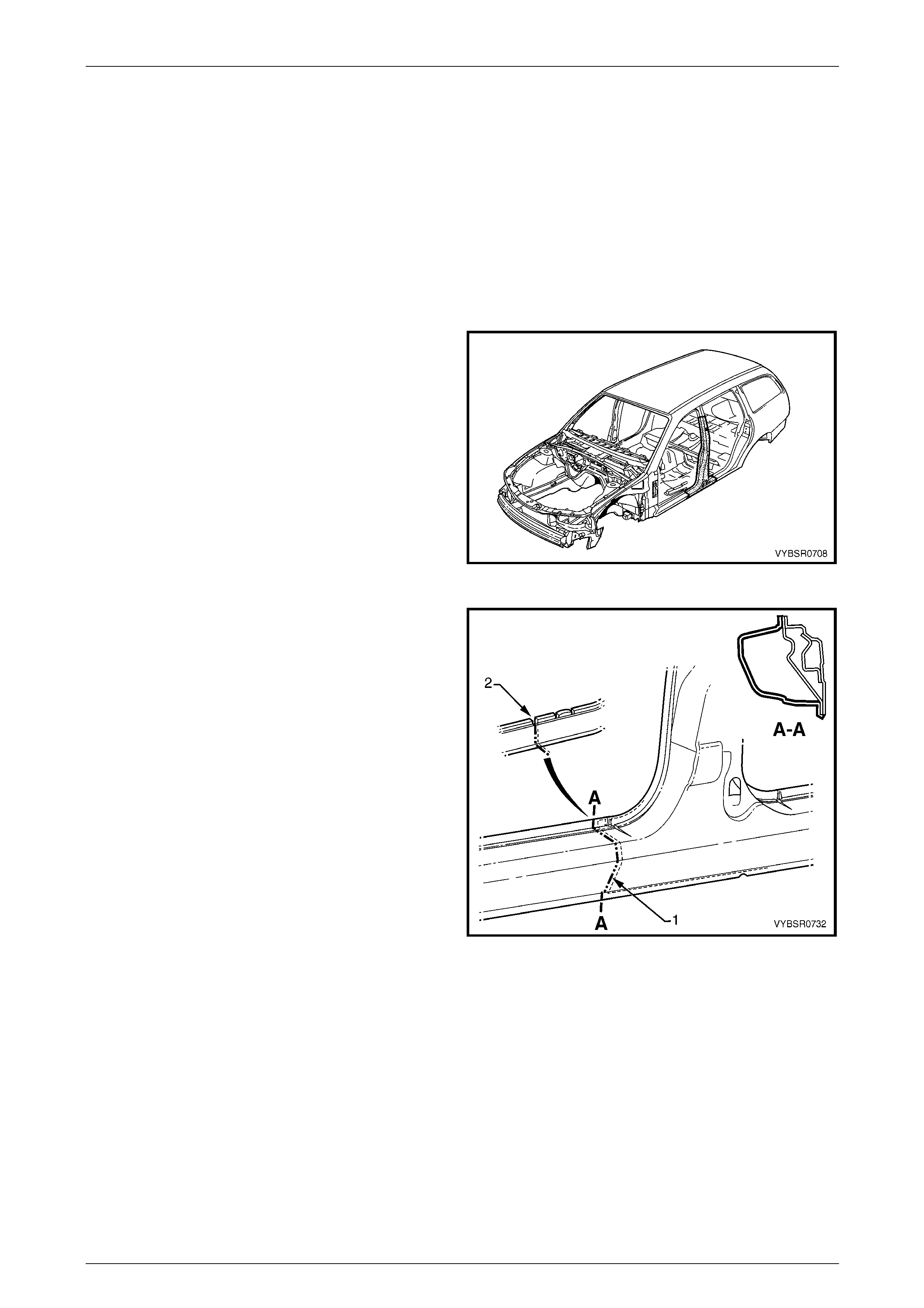
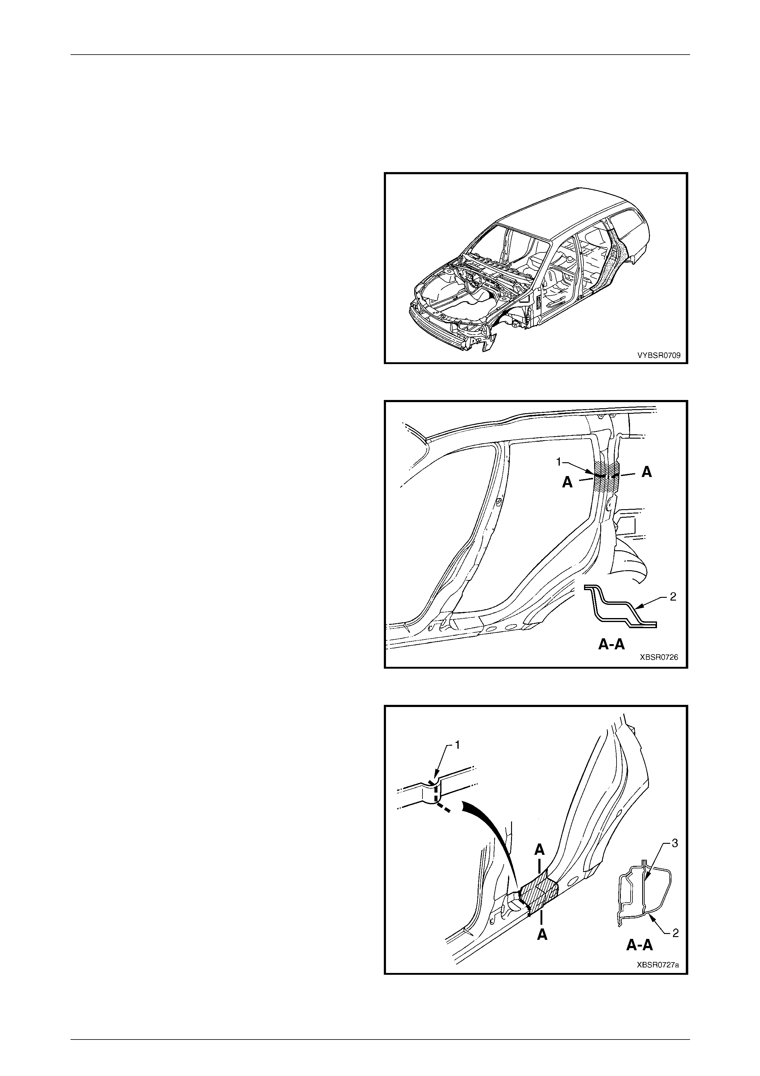
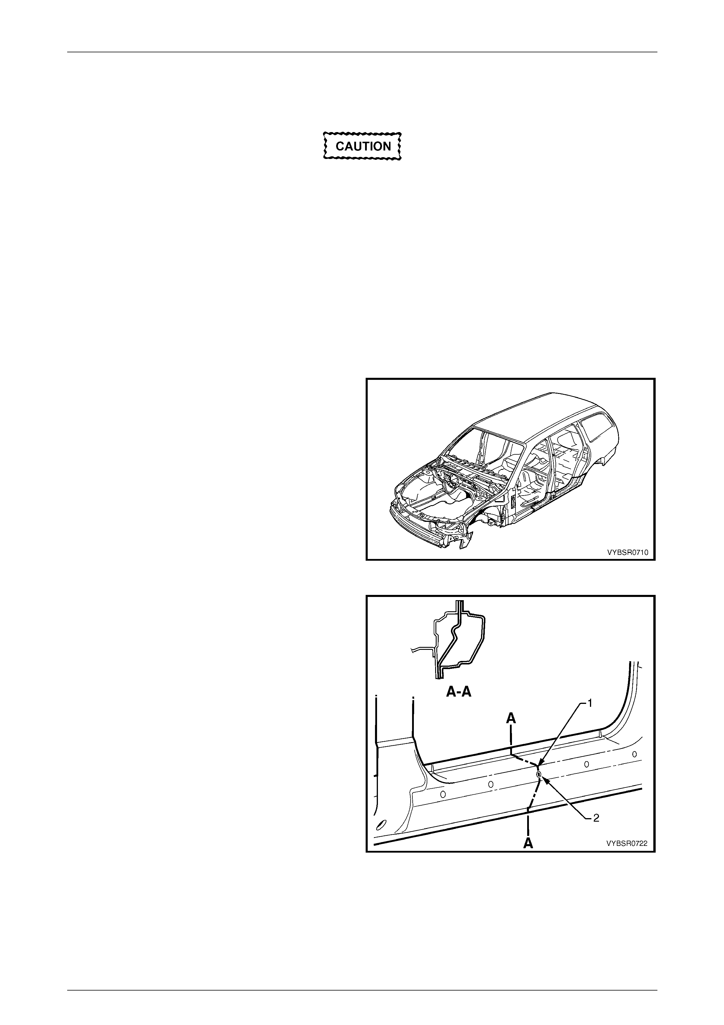
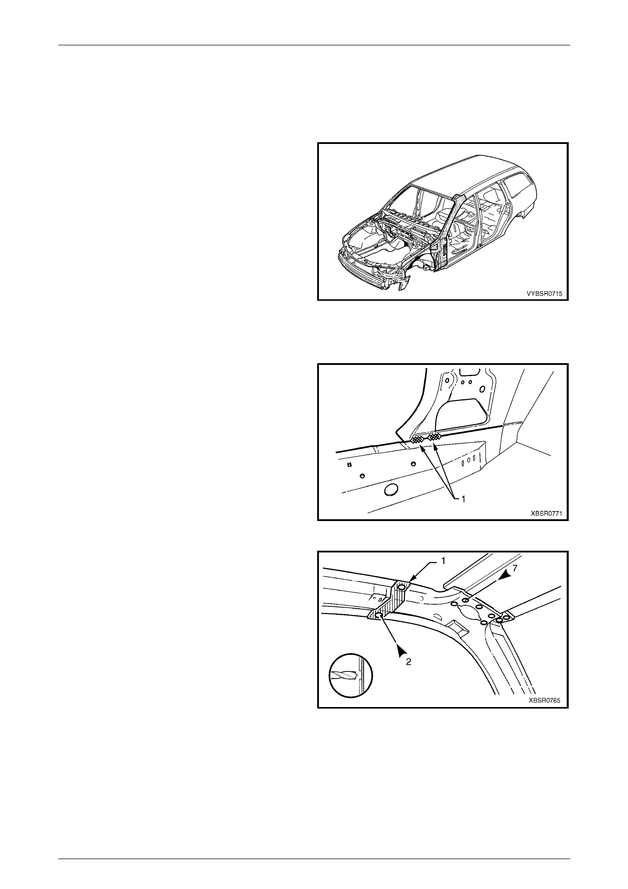
The shaded components in Figure 7B – 1 are those dealt
with in this Section.
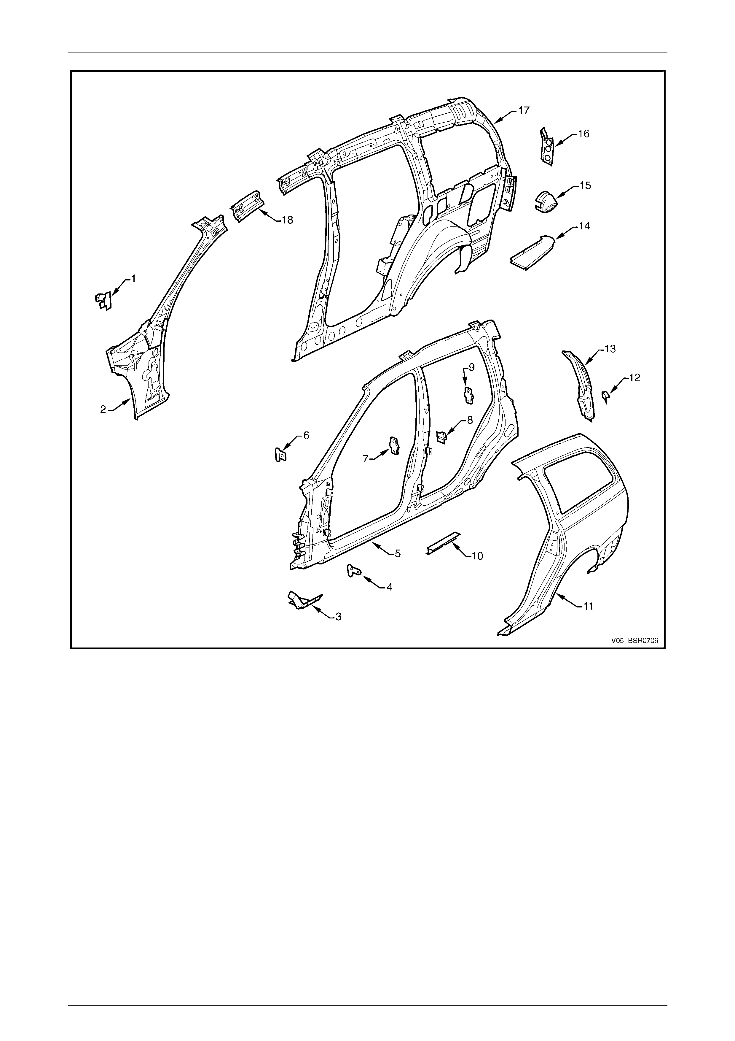
The components and assemblies shown in
Figure 7B – 2 are the serviceabl e parts that form
the basis of the repair procedures in this Secti on.
For a detailed view of the body components,
refer to Section 3B Body Construction – Wagon.
NOTE
Always refer to an Authorised Retailer for spare
parts availability configurations.
Cavity foam may be used within the hinge,
centre and lock pillars. Care needs to be
taken when repairing the vehicle in these
areas, refer to Section 2 Precautions prior to
beginning any work for further information
regarding the use of cavity foam.
Figure 7B – 1
7B Body Side – Wagon Page 7B-4
Page 7B-4
Figure 7B – 2
Legend
1 Hinge Pillar Trim Panel Bracket, Left-hand / Right-hand
2 Hinge Pillar Inner Panel Assembly, Left-hand / Right-hand
3 Fender Lower Rear Bracket, Left-hand / Right-hand
4 Fender Rear Bracket, Left-hand / Right-hand
5 Door Opening Frame Assembly, Left-hand / Right-hand
6 Fender Upper Rear Bracket, Left-hand / Right-hand
7 Front Door Striker Anchor Plate, Left-hand / Right-hand
8 Rear Door Check Link Bracket, Left-hand / Right-hand
9 Rear Door Striker Anchor Plate, Left-hand / Right-hand
10 Underbody Jacking Locator, Left-hand / Right-hand
11 Rear Quarter Panel, Left-hand / Right-hand
12 Rear Bumper Fascia Side bracket, Left-hand / Right-hand
13 Quarter Panel Extension, Left-hand / Right-hand
14 Quarter Outer Lower Rear Panel, Left-hand / Right-hand
15 Fuel Filler Pipe Housing, Right-hand
16 Quarter Inner Lower Rear Extension, Left-hand / Right-hand
17 Quarter Panel Inner Assembly, Left-hand / Right-hand
18 Quarter Panel Inner Extension, Left-hand / Right-hand
NOTE
• Door opening frame assembly (4) includes
parts 5, 6, 7, 8, 9 and 10.
• Quarter panel inner assembly (16) includes
parts 16 and the rear wheelhouse inn er panel
assembly which is also available separately,
refer to Section 10B Body Rear – Wagon.
7B Body Side – Wagon Page 7B-5
Page 7B-5
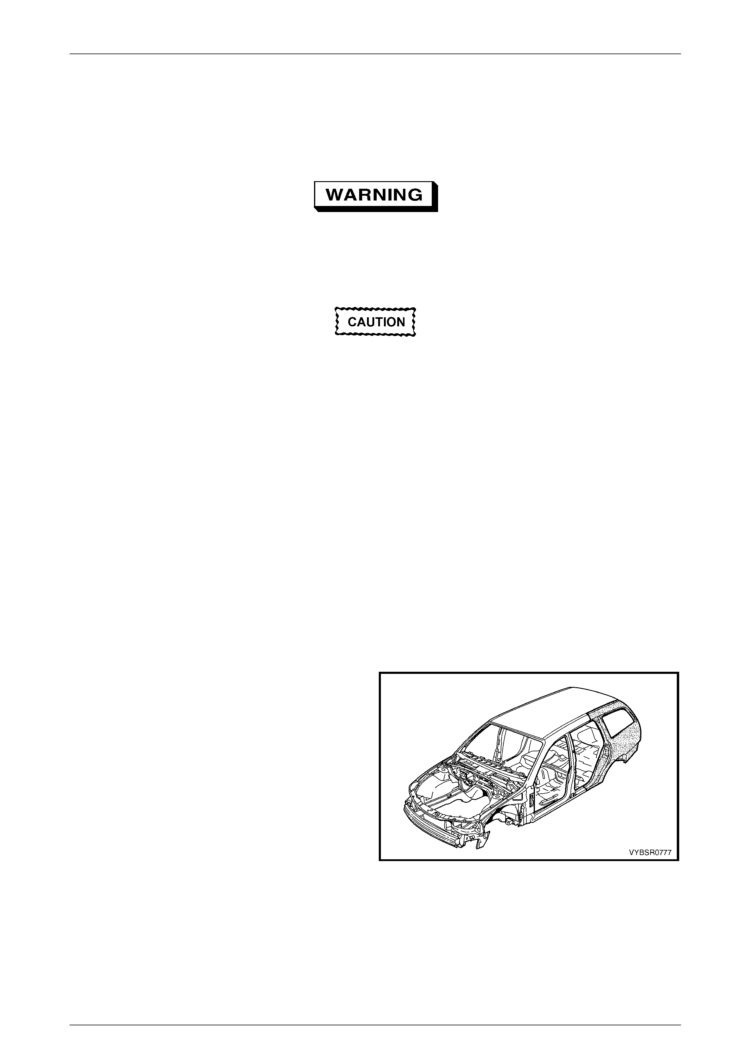
2 Service Operations
2.1 Rear Quarter Panel – Replace
To avoid the possibility of fire, take particular
care when cuttin g or w elding at the r ear of th e
vehicle. Remove the fuel tank and plug the
fuel lines.
Before performing any operations on
the rear quarter panel, remove the
Stuffer Block from within the rear
quarter panel inner cavity. Refer to
Section 3B Body Construction – Wagon.
NOTE
• This procedure detai ls the removal of the rear
quarter panel as an assembly with the tail
lamp housing, quarter panel upper extension,
quarter panel lower extension and fuel filler
pipe housing (for right-hand side). However
these parts are not available as an assembly
and must be ordered separately.
• Full replacement of the rear quarter panel
requires removal of the roof panel. This
procedure includes both full panel
replacement and partial replacement that
avoids removal of the roof panel.
Remove
1 Remove the adjacent bolt-on panels a nd components
as described in the appropriate Section of the MY2005
VZ Service Information.
2 Remove the rear window, refer to
Section 1A6 Stationary Windows in the MY2005 VZ
Service Information.
3 If full panel replacement is to be performed,
remove the roof joint moulding ,
refer to Section 3B Body Construction – Wagon, and
remove the roof panel, refer to Section 9B Roof.
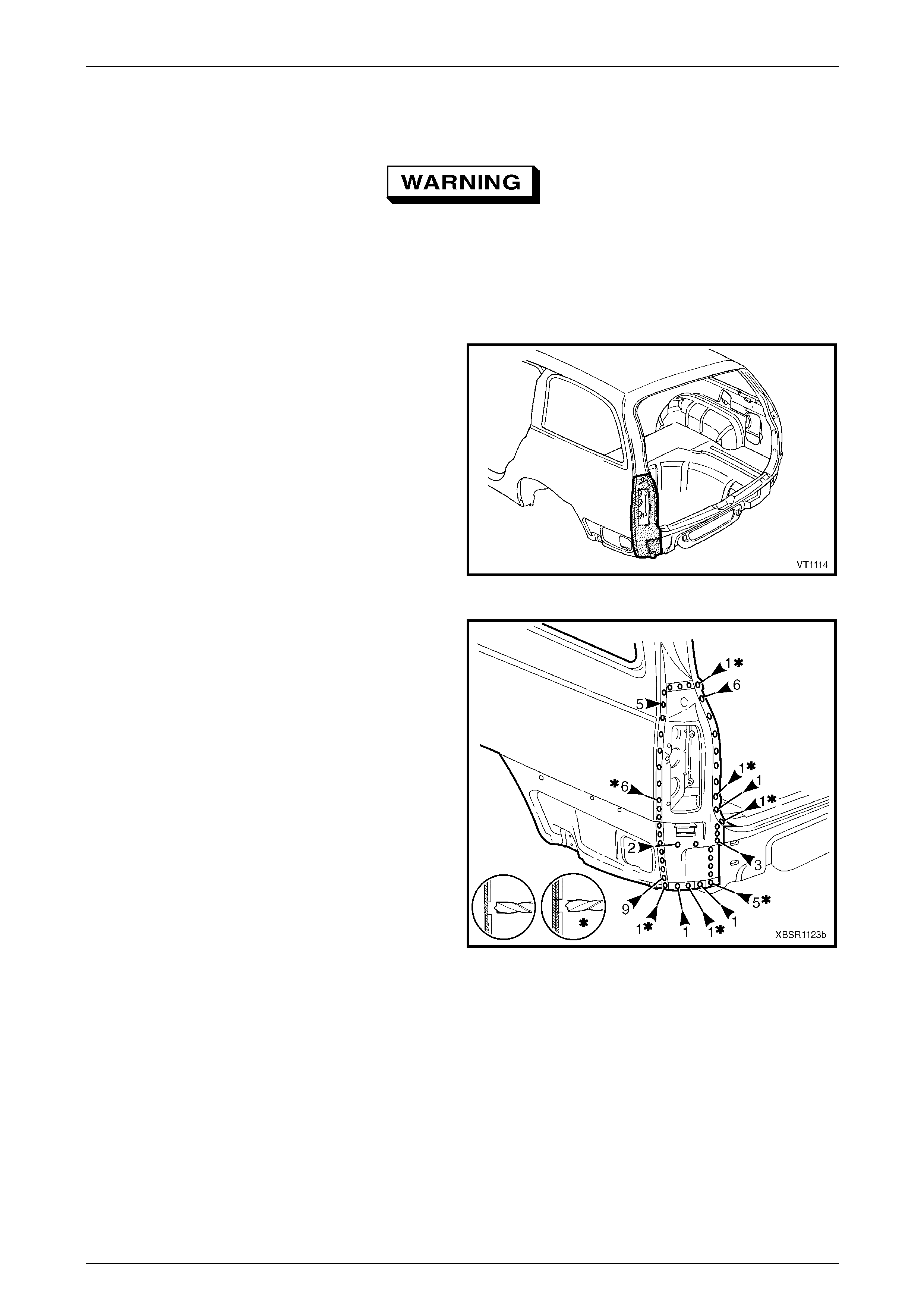
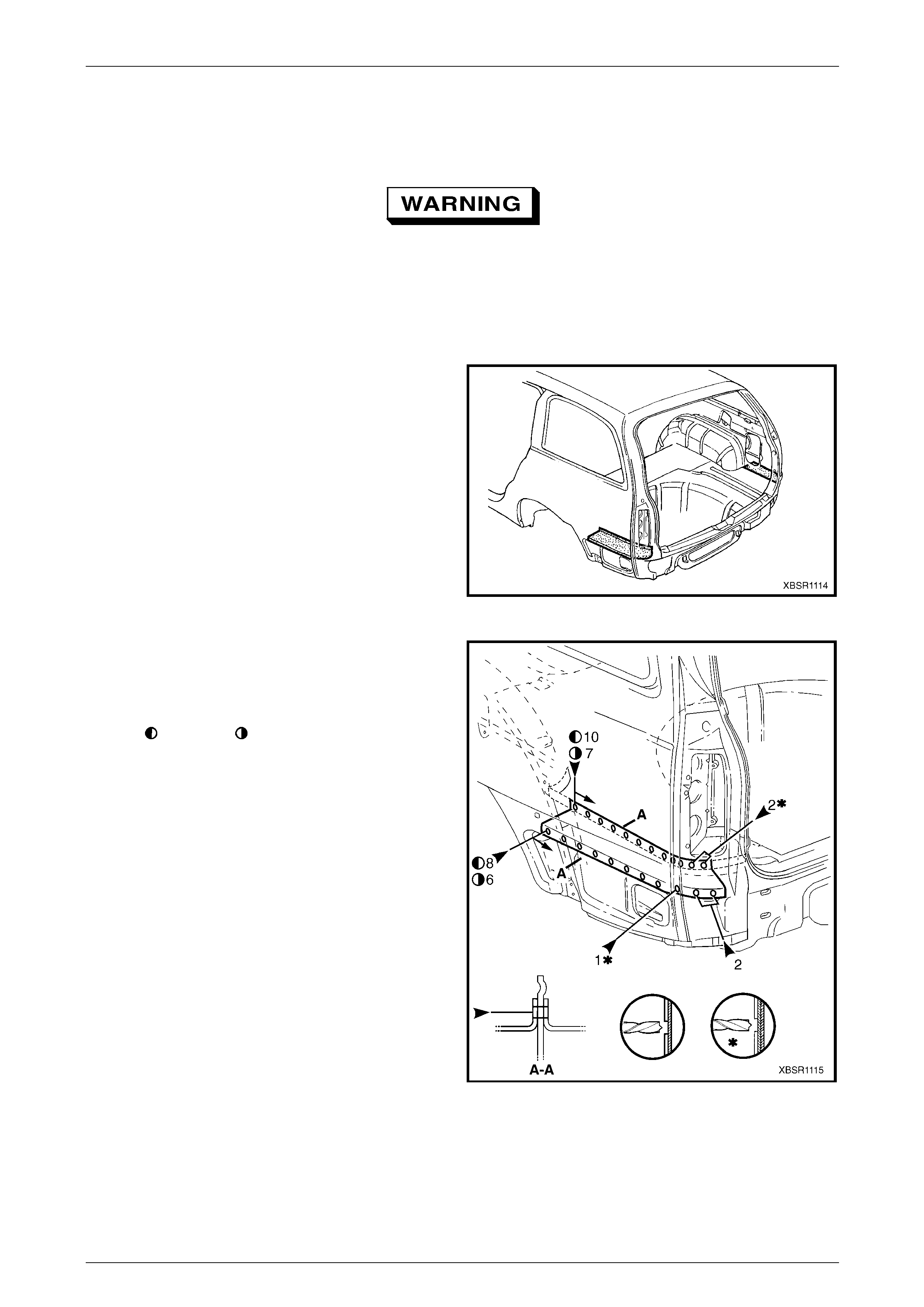
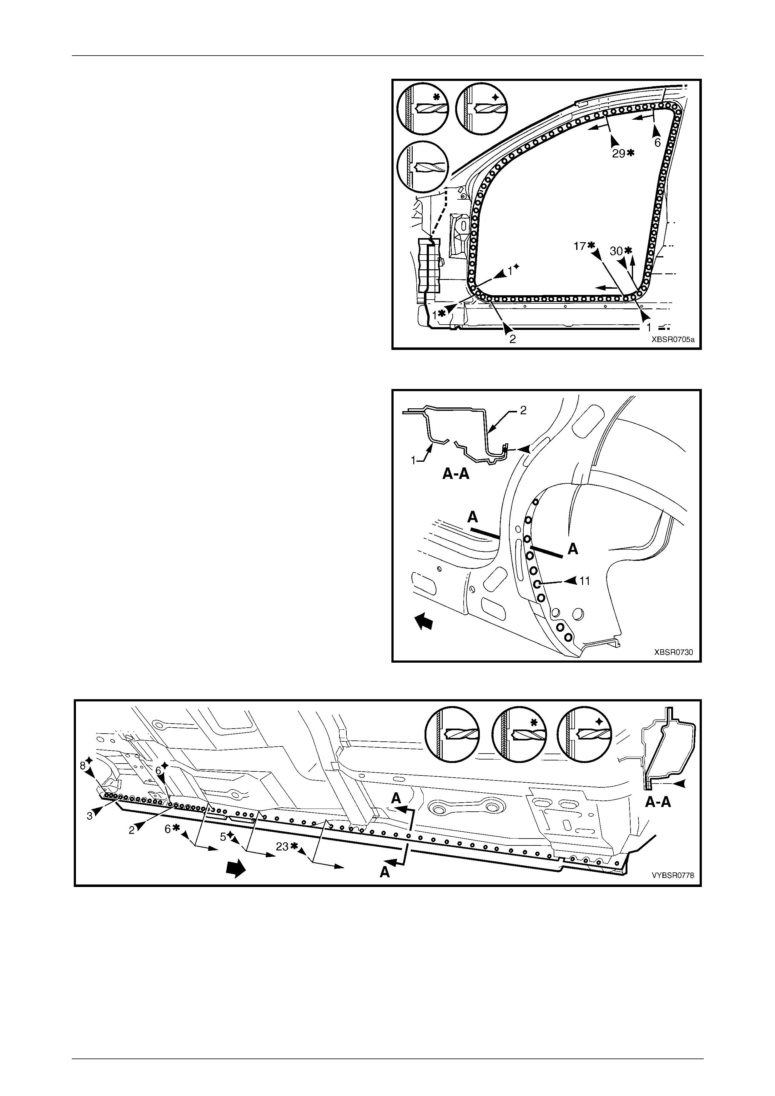
Figure 7B – 3
7B Body Side – Wagon Page 7B-6
Page 7B-6
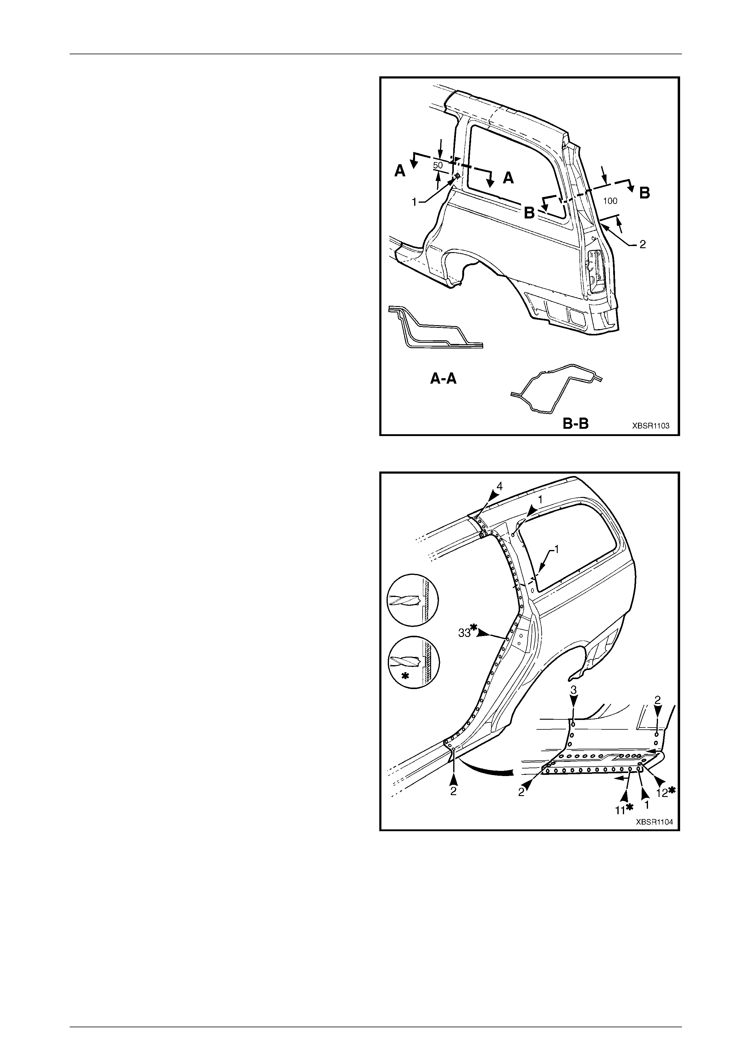
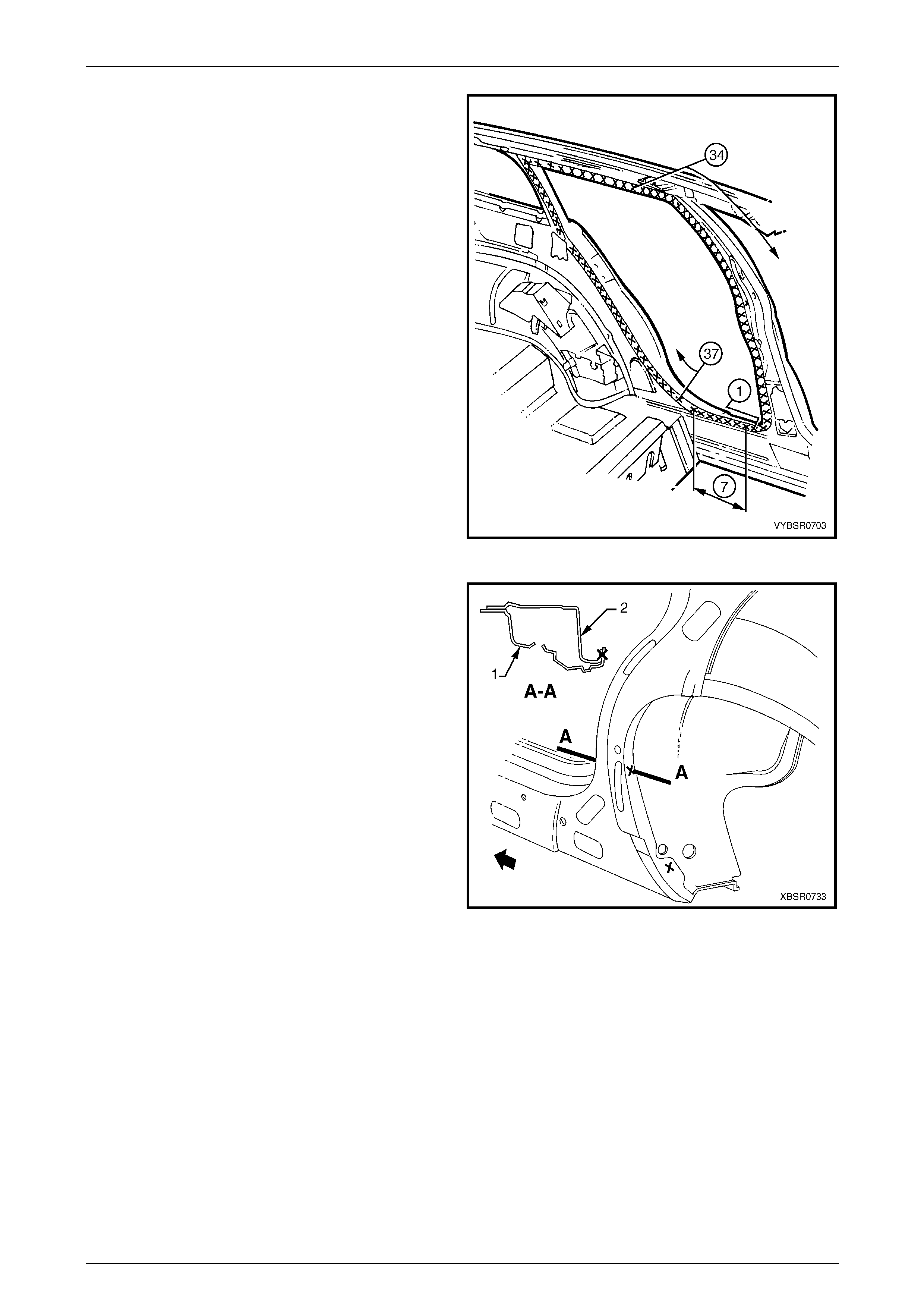
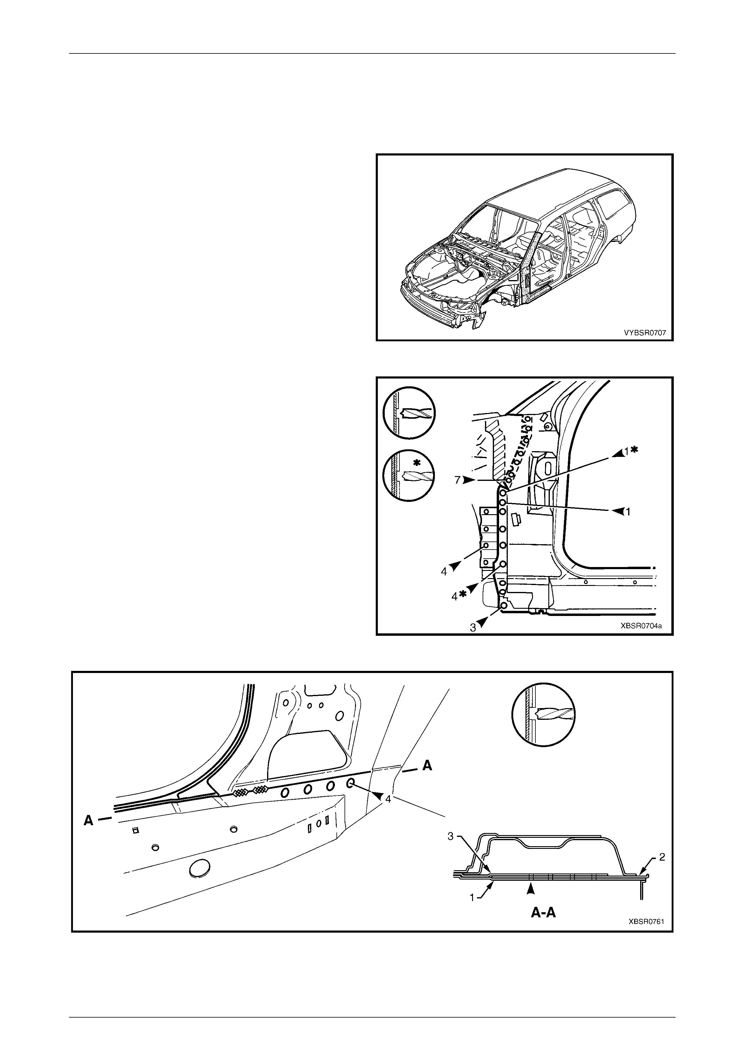
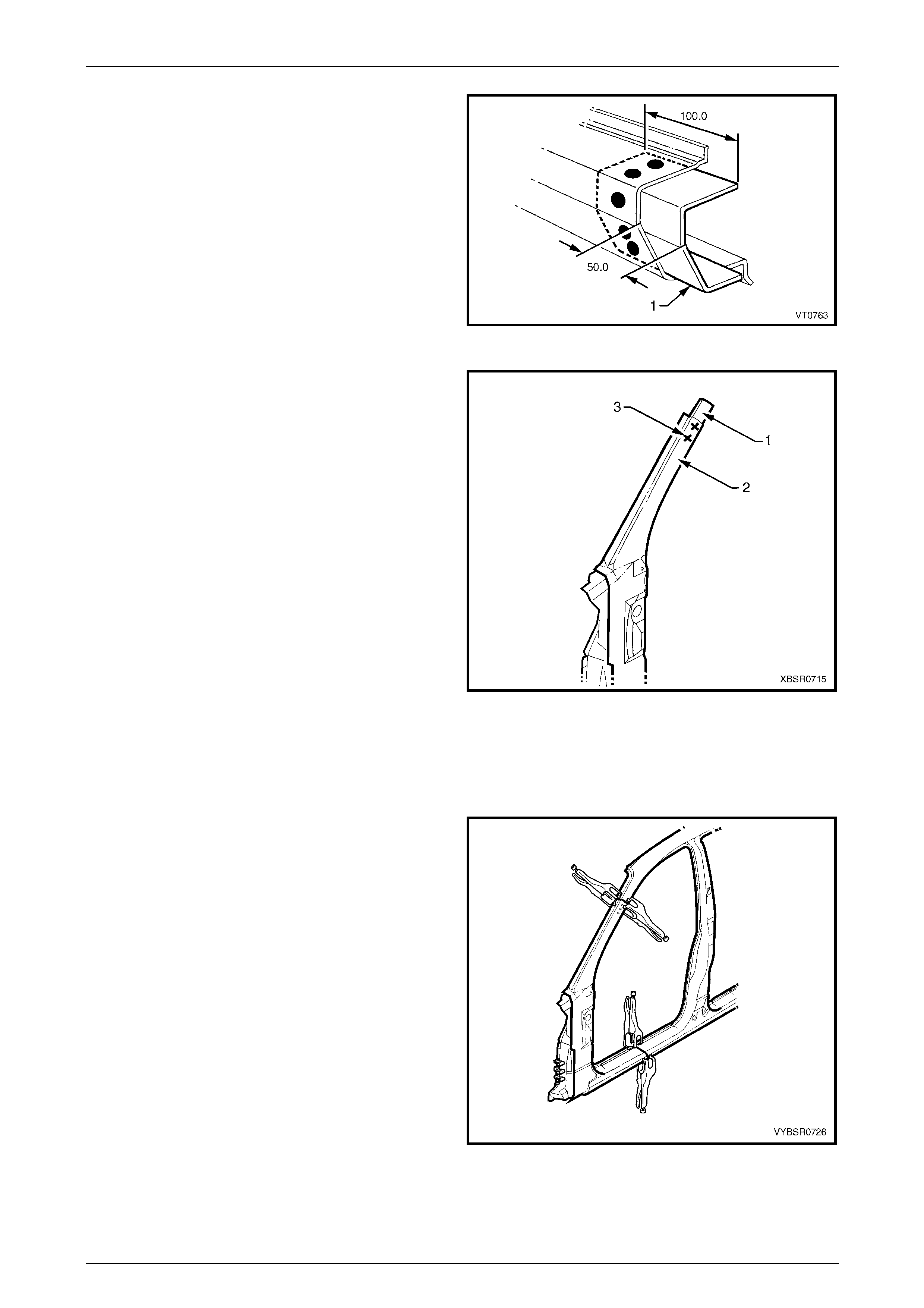
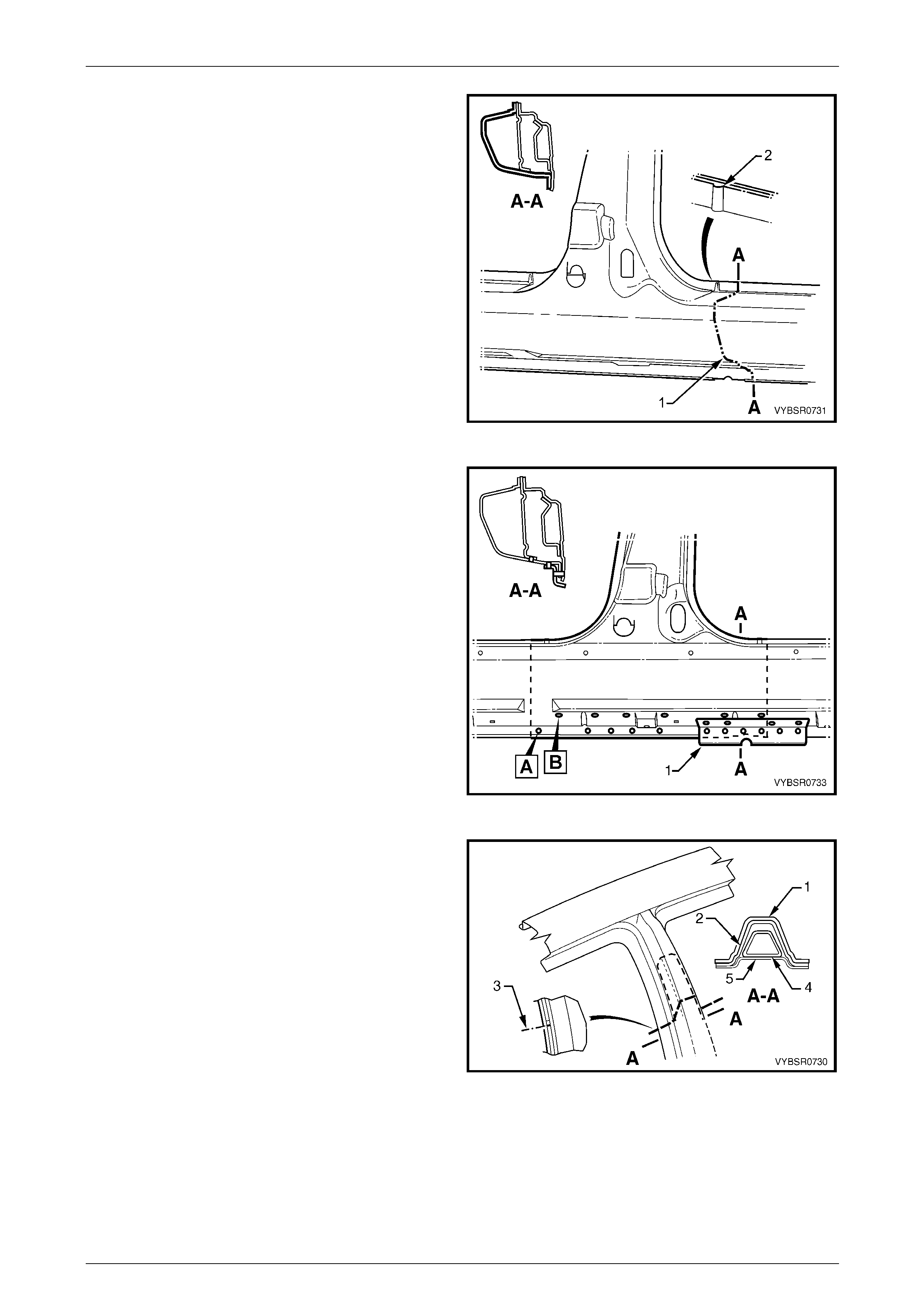
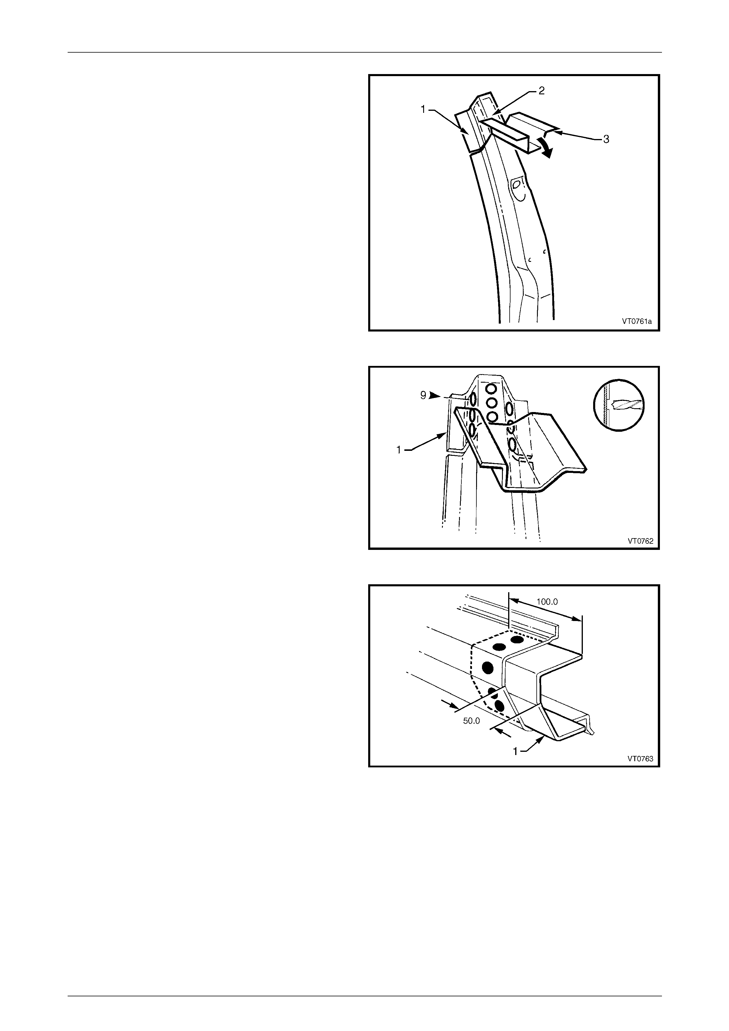
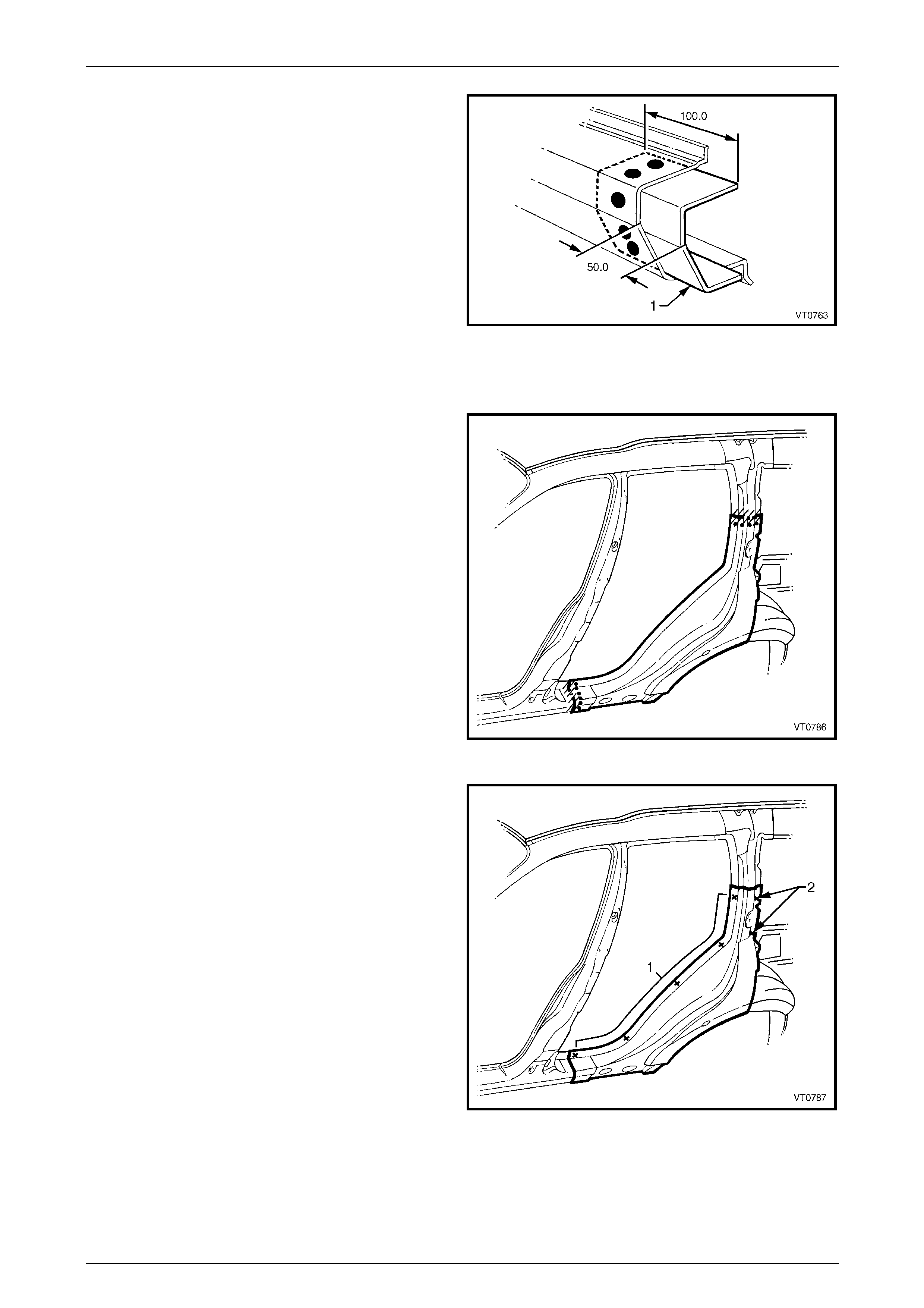
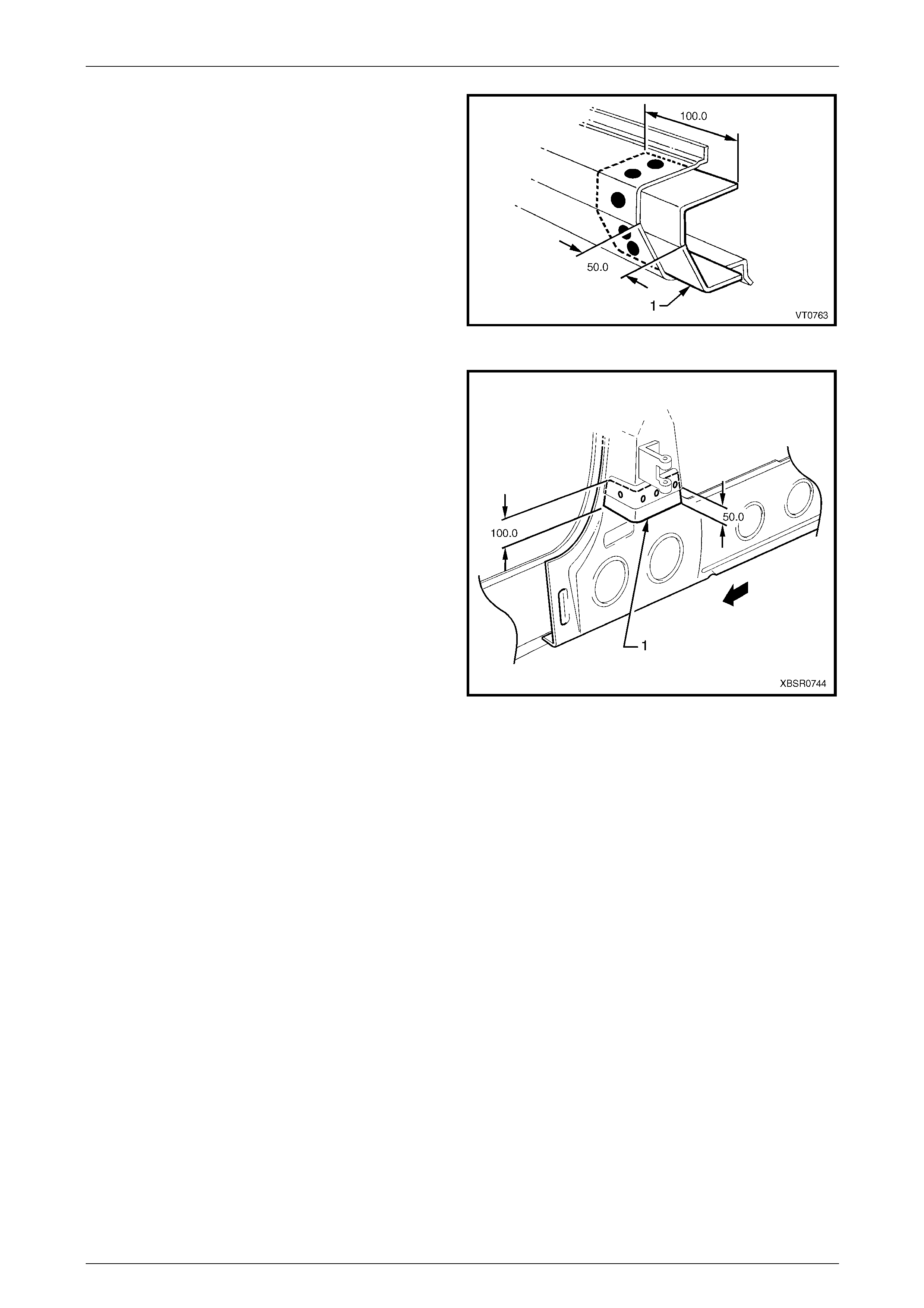
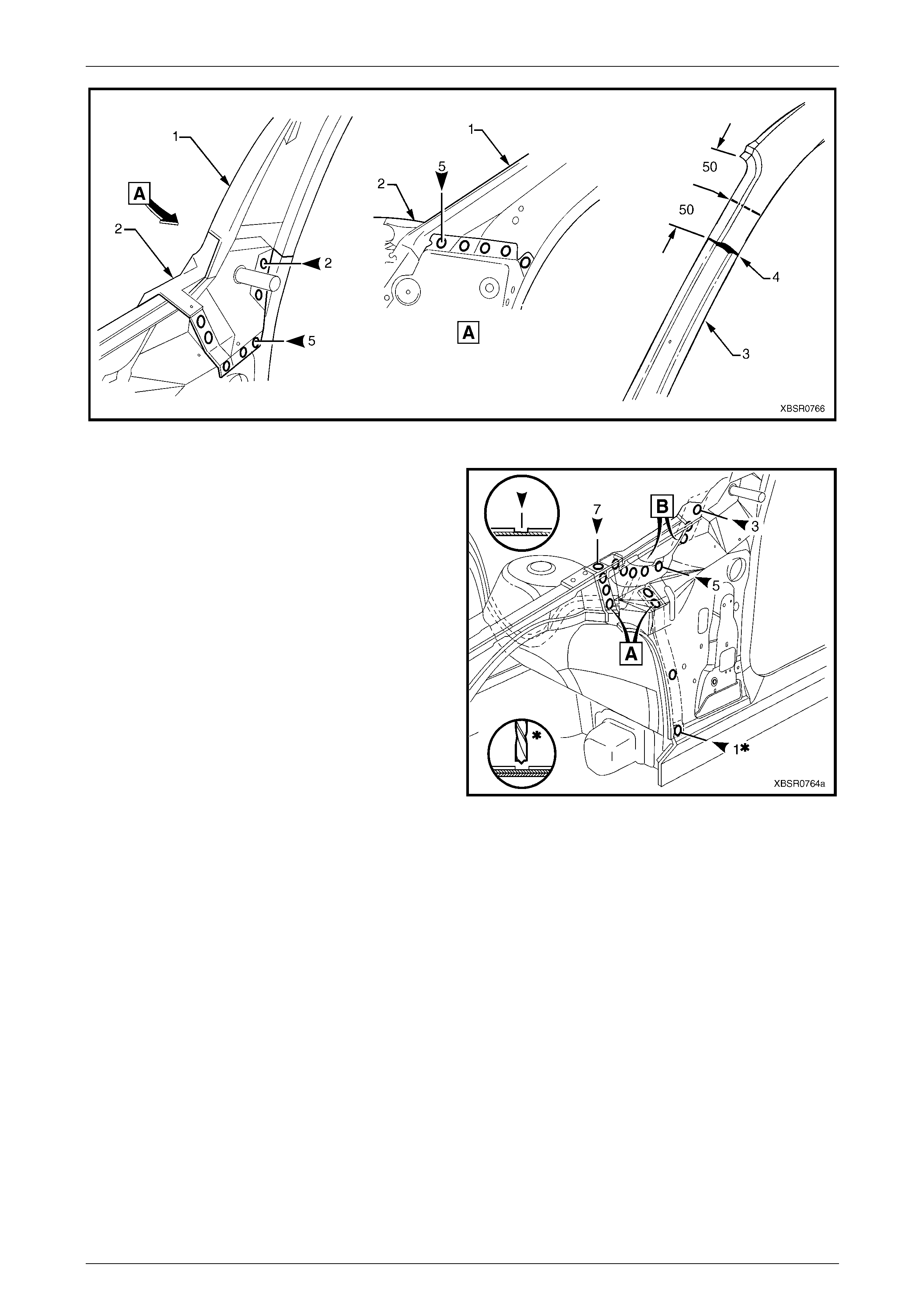
4 Partial replacement of the rear quarter panel is
possible by cutting the panel through the lock pillar,
50 mm above the datum hole (1) and the back pillar,
100 mm above the quarter panel extension (2). Ensure
that only the outer panel is cut.
Figure 7B – 4
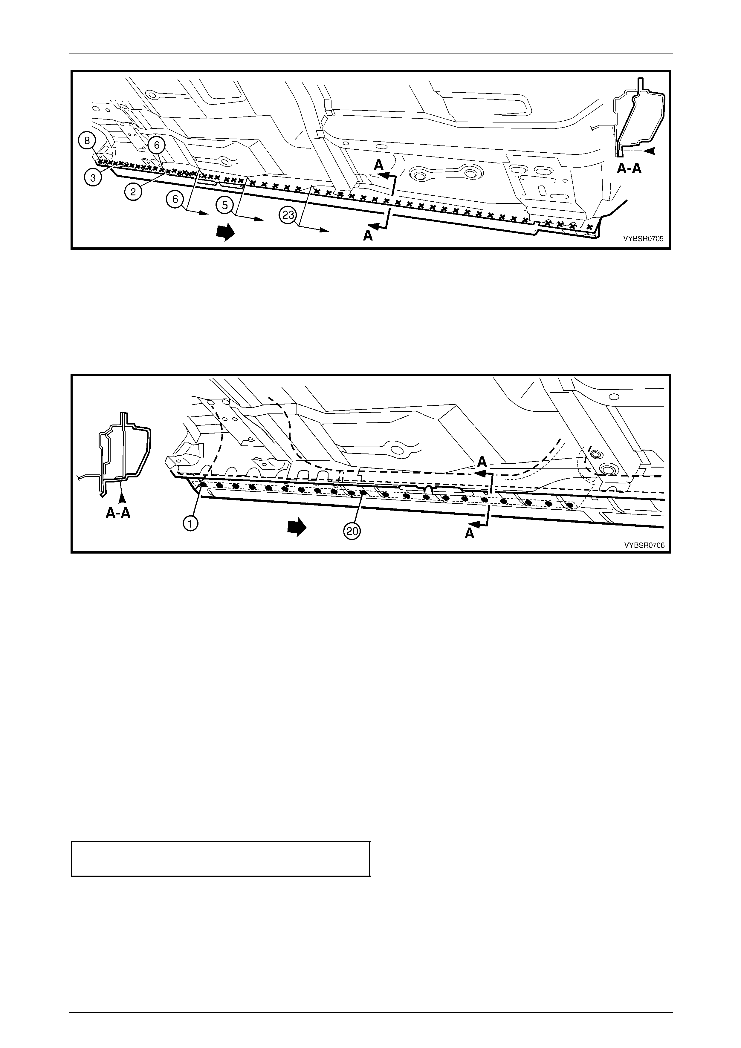
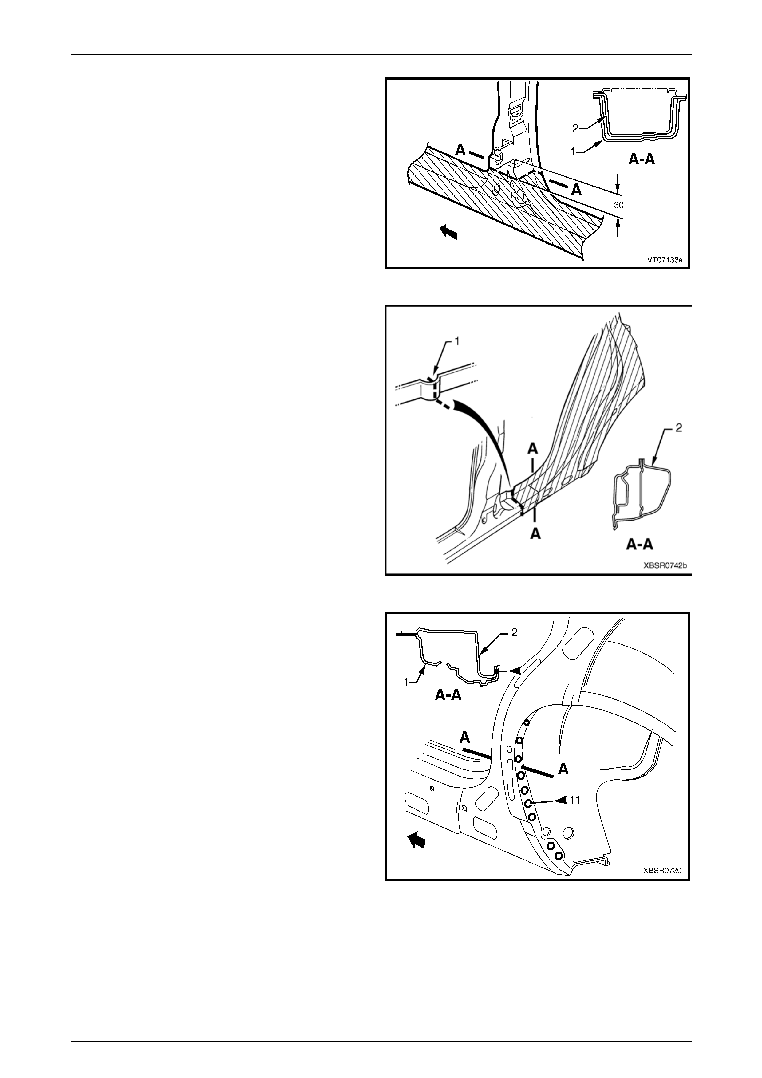
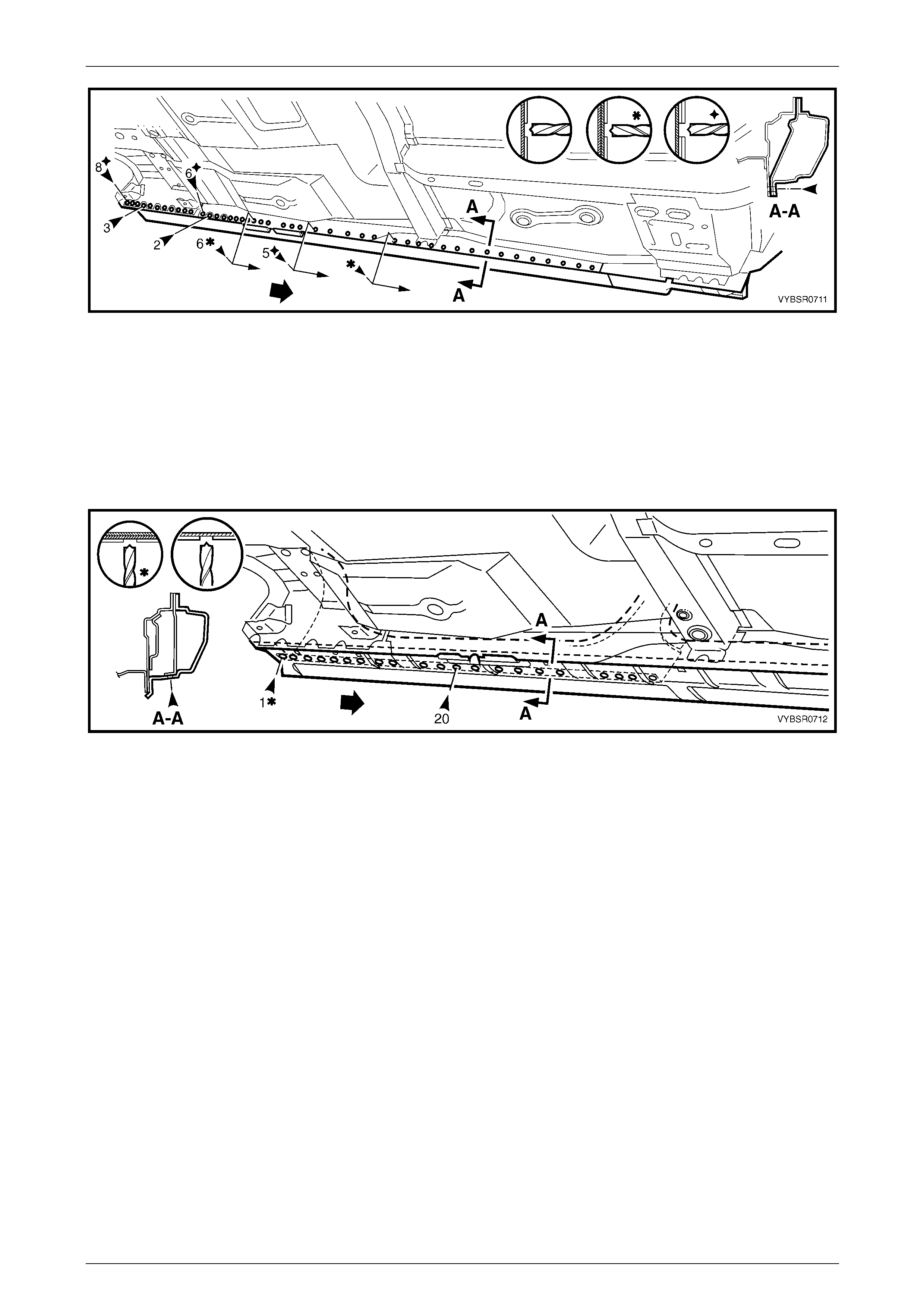
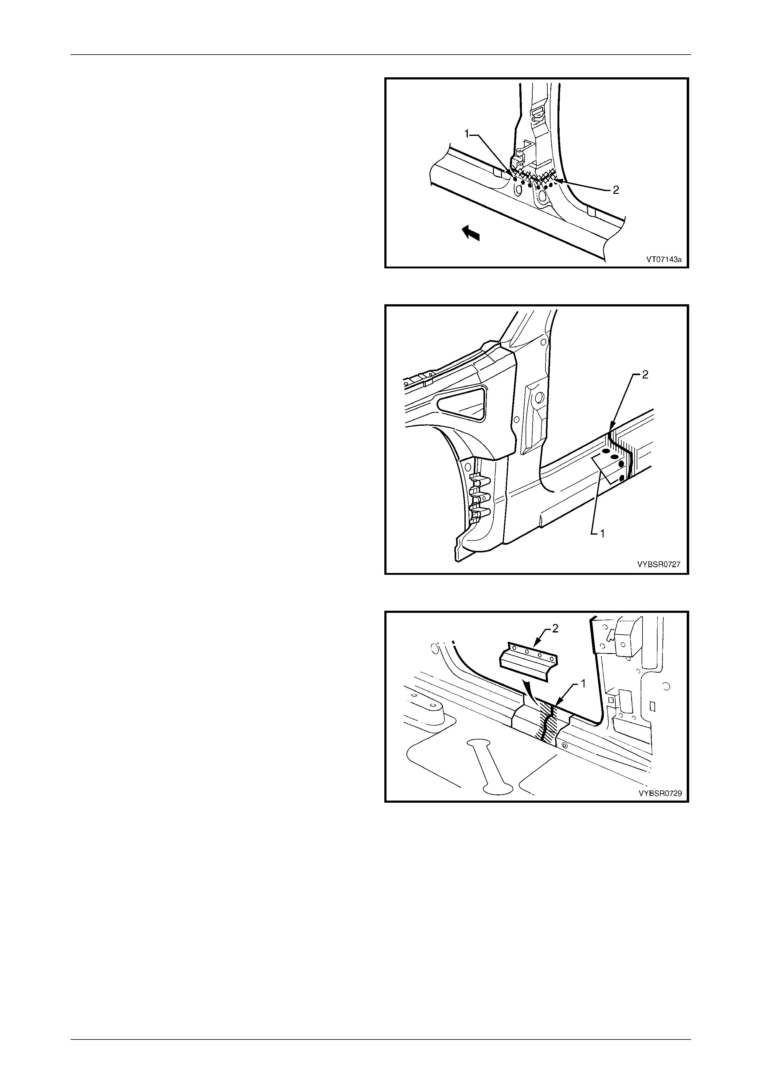
5 Spot cut the welds attaching the rear quarter panel
around the rear door opening and under the rocker
panel area. If a partial replacement is being
performed, remove the welds only to the cut point (1).
Figure 7B – 5
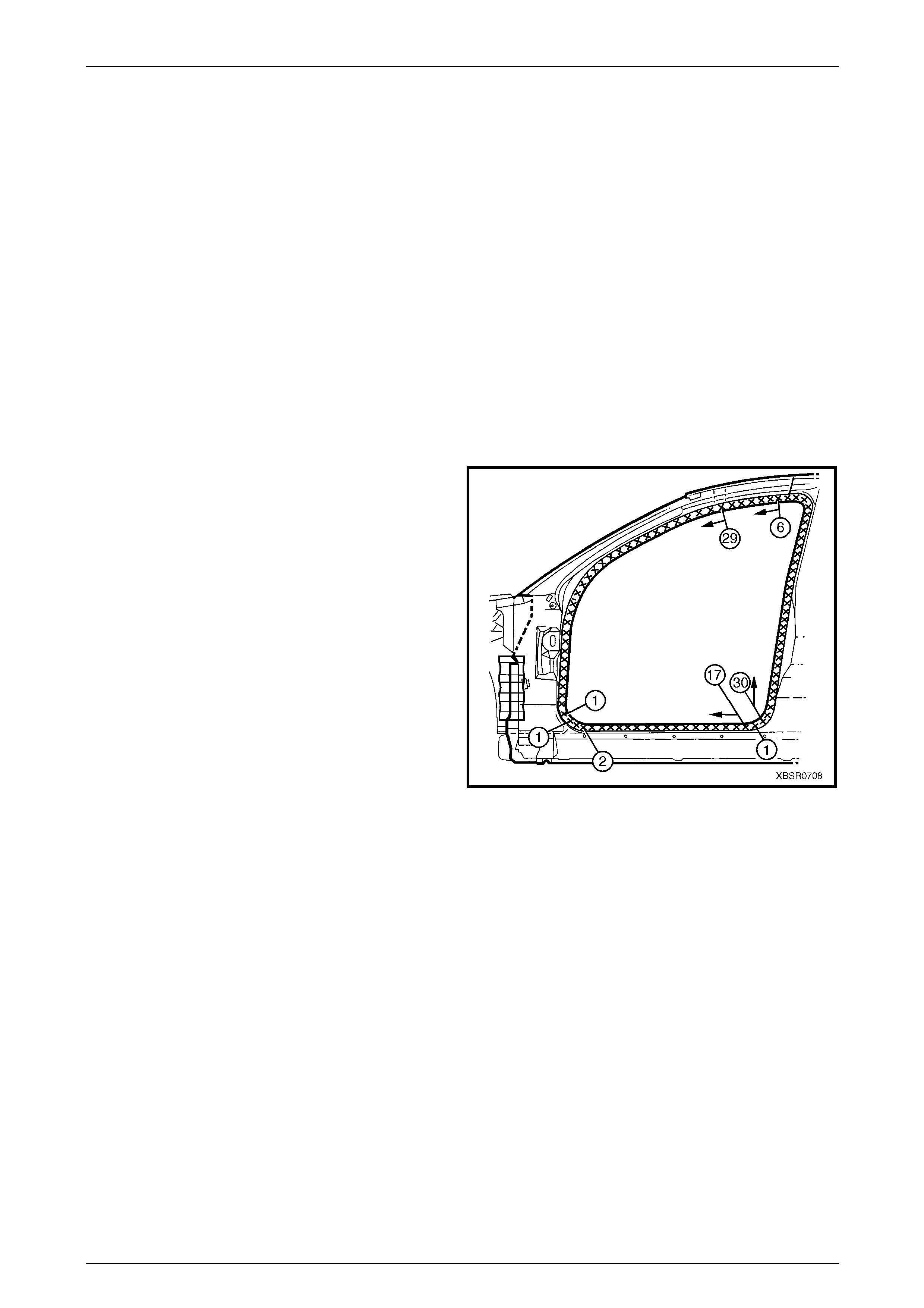
7B Body Side – Wagon Page 7B-7
Page 7B-7
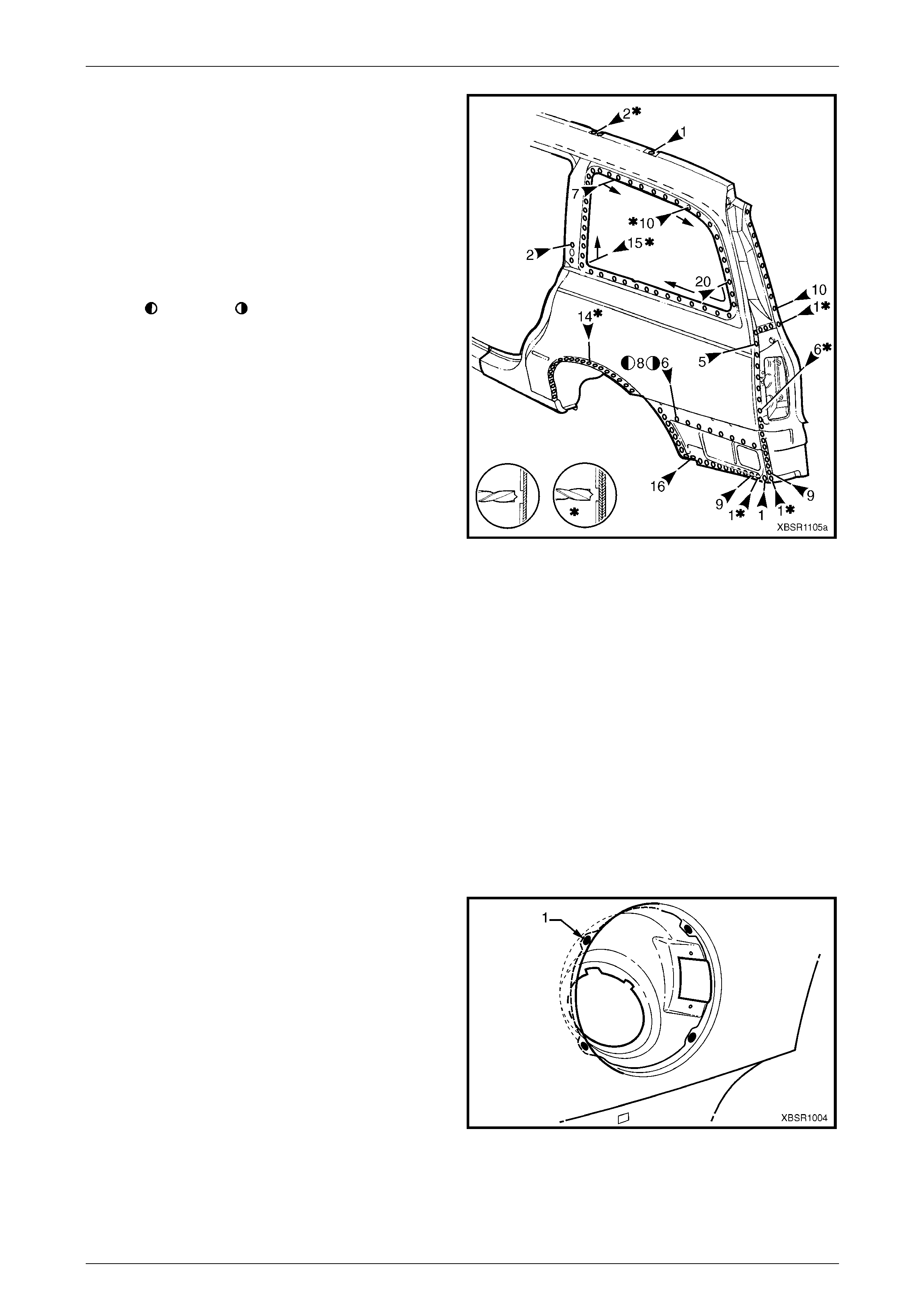
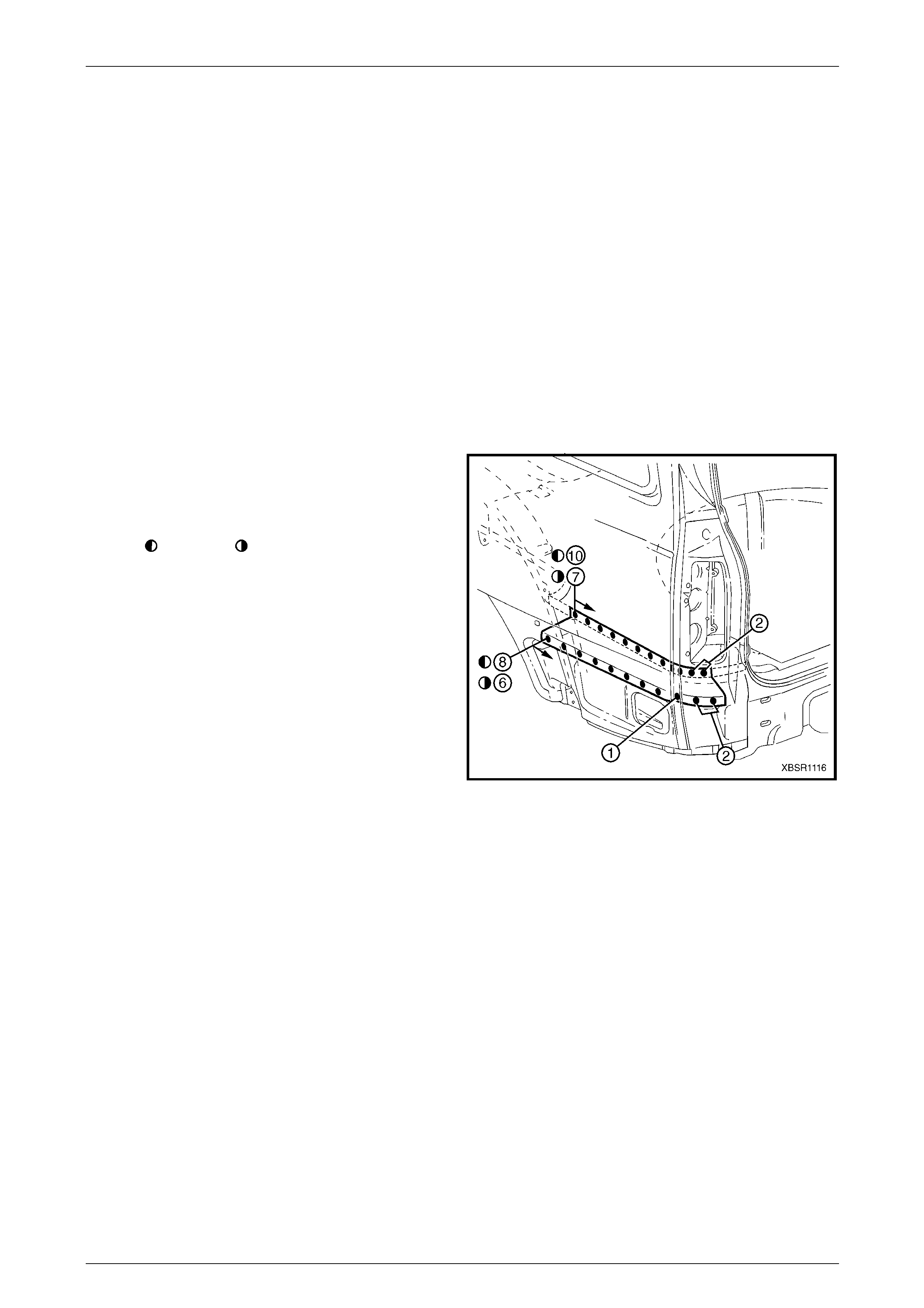
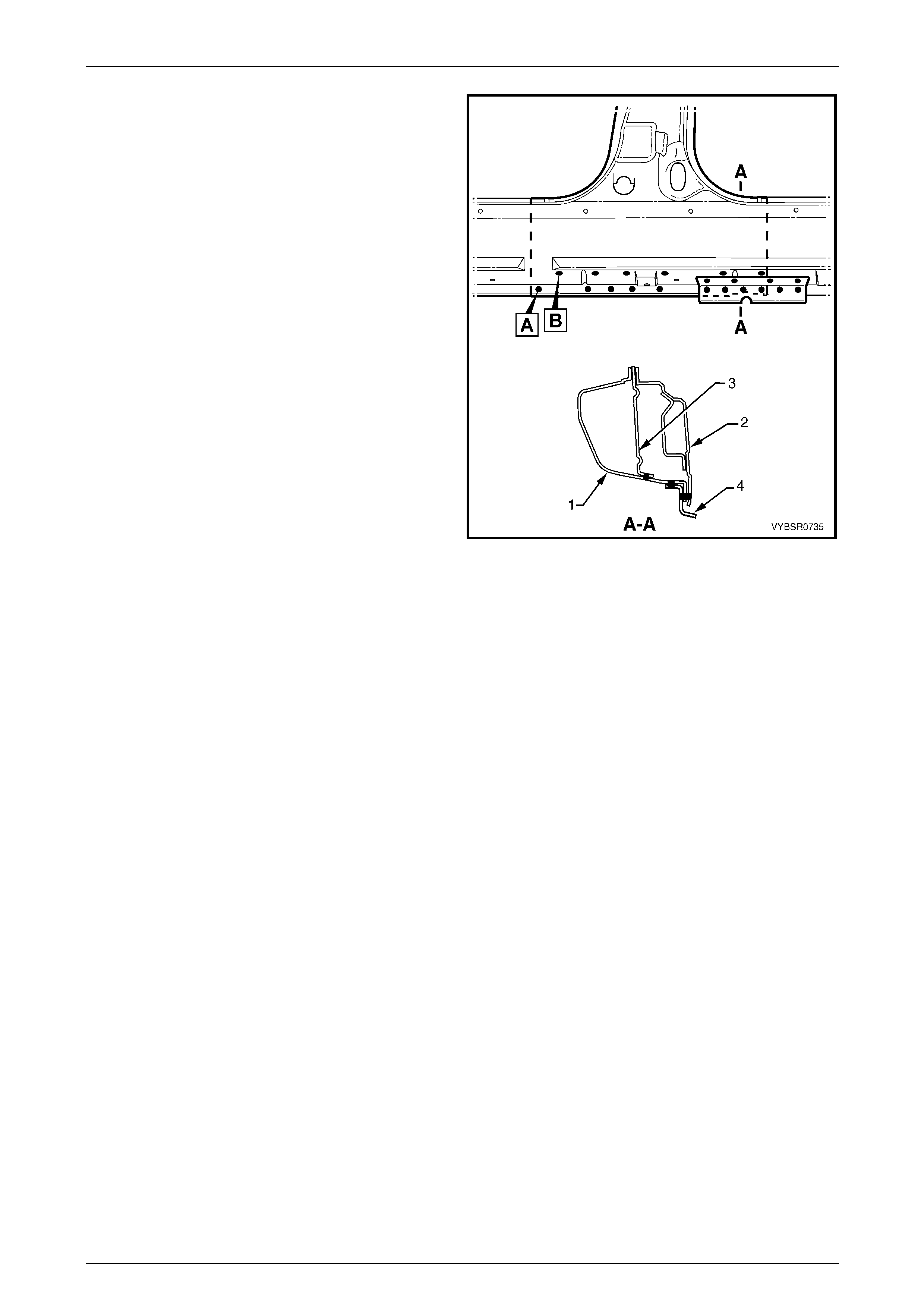
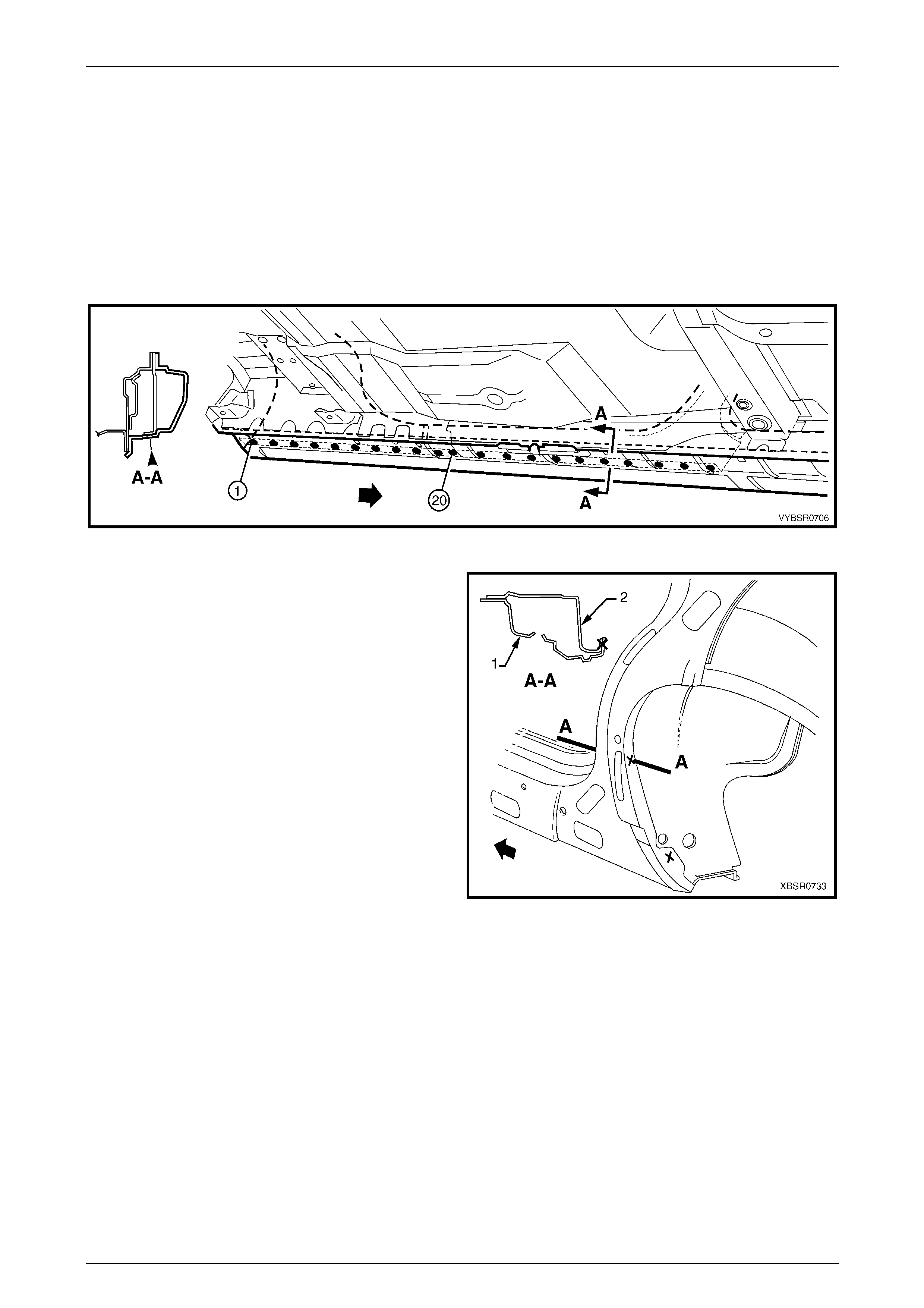
6 Spot cut the welds attaching the rear quarter panel to
the quarter panel inner assembly and quarter outer
lower rear panel and quarter panel extension. If a
partial replacement is being performed, remove the
welds only to the cut points.
NOTE
The quarter panel extension can be removed
with the rear quarter panel if required.
Refer to 2.2 Quarter Panel Extension –
Replace.
• = left-hand, = right-hand
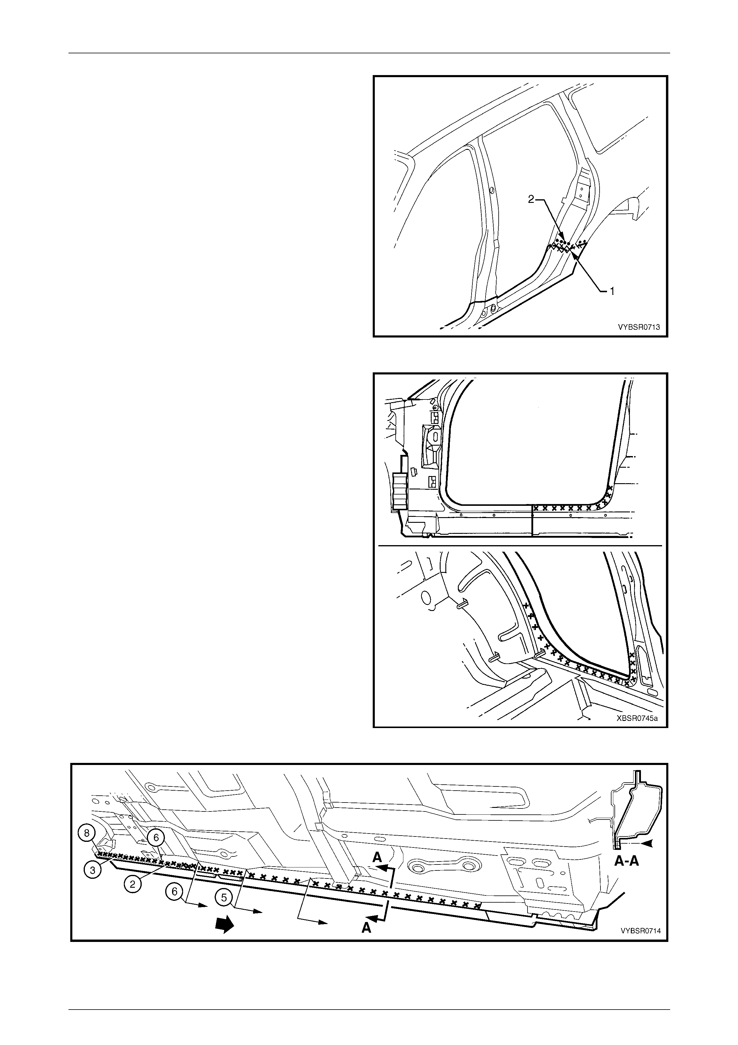
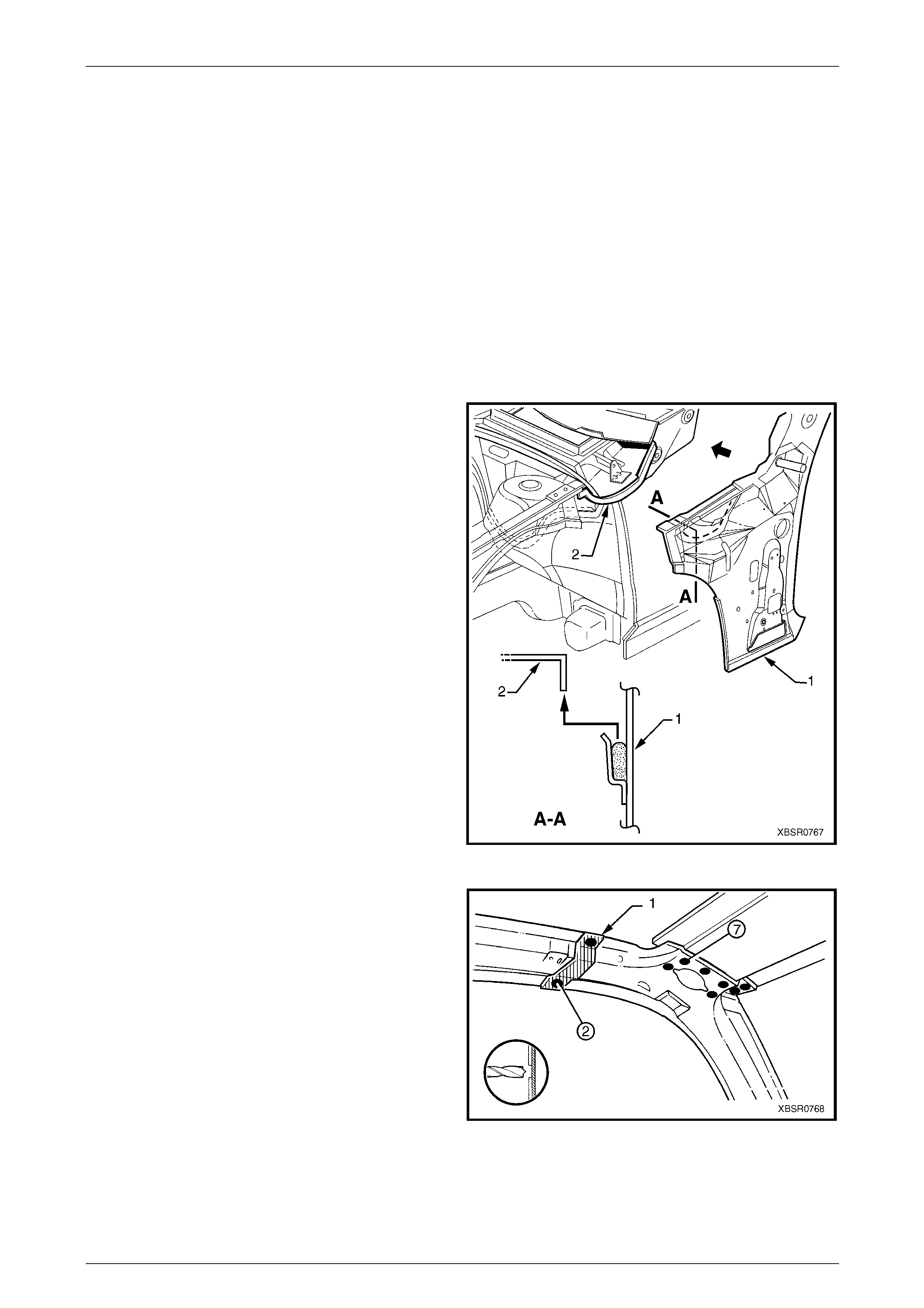
7 Remove the rear quarter panel from the vehicle, then
repair any damage to adjacent parts as required.
8 Check and rectify the alignme nt of the bod y as
required, refer to Section 3B Body Construc tion –
Wagon.
Figure 7B – 6
Replace
NOTE
• Spot welding is the preferred method for
attaching of panels and should be used
whenever possible. Where the spot welding
equipment available will not access the
required weld position, a plug weld should be
performed.
• The same number and position of spot welds
(or plug welds) should be used when
replacing the panel, as was used during
manufacture, in order to maintain the original
structural strength of the vehicle.
1 If performing a partial panel replac ement, cut the new panel at the lock and back pillars to match the vehi cle.
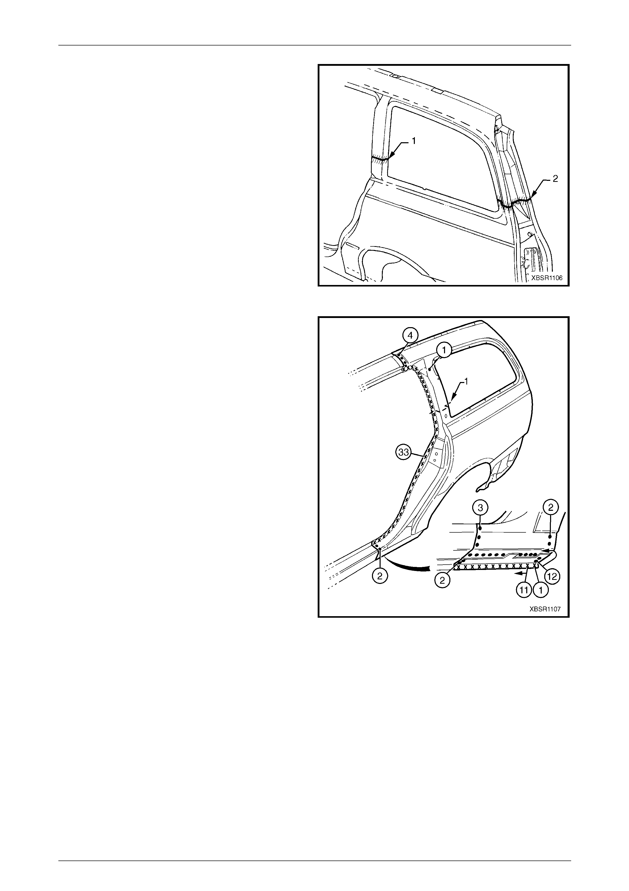
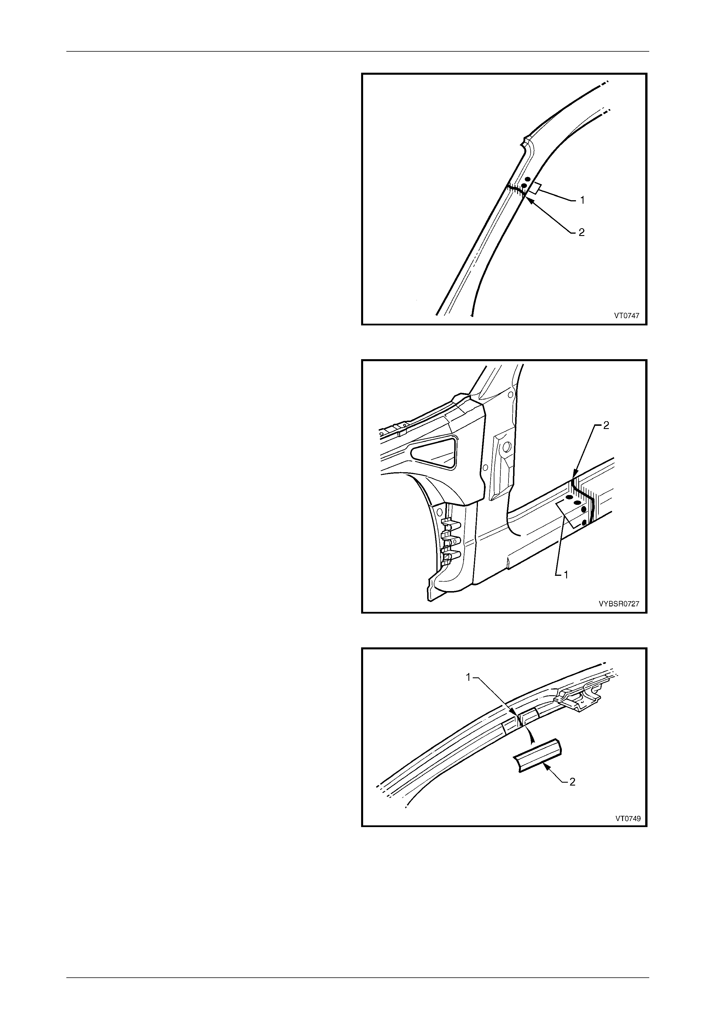
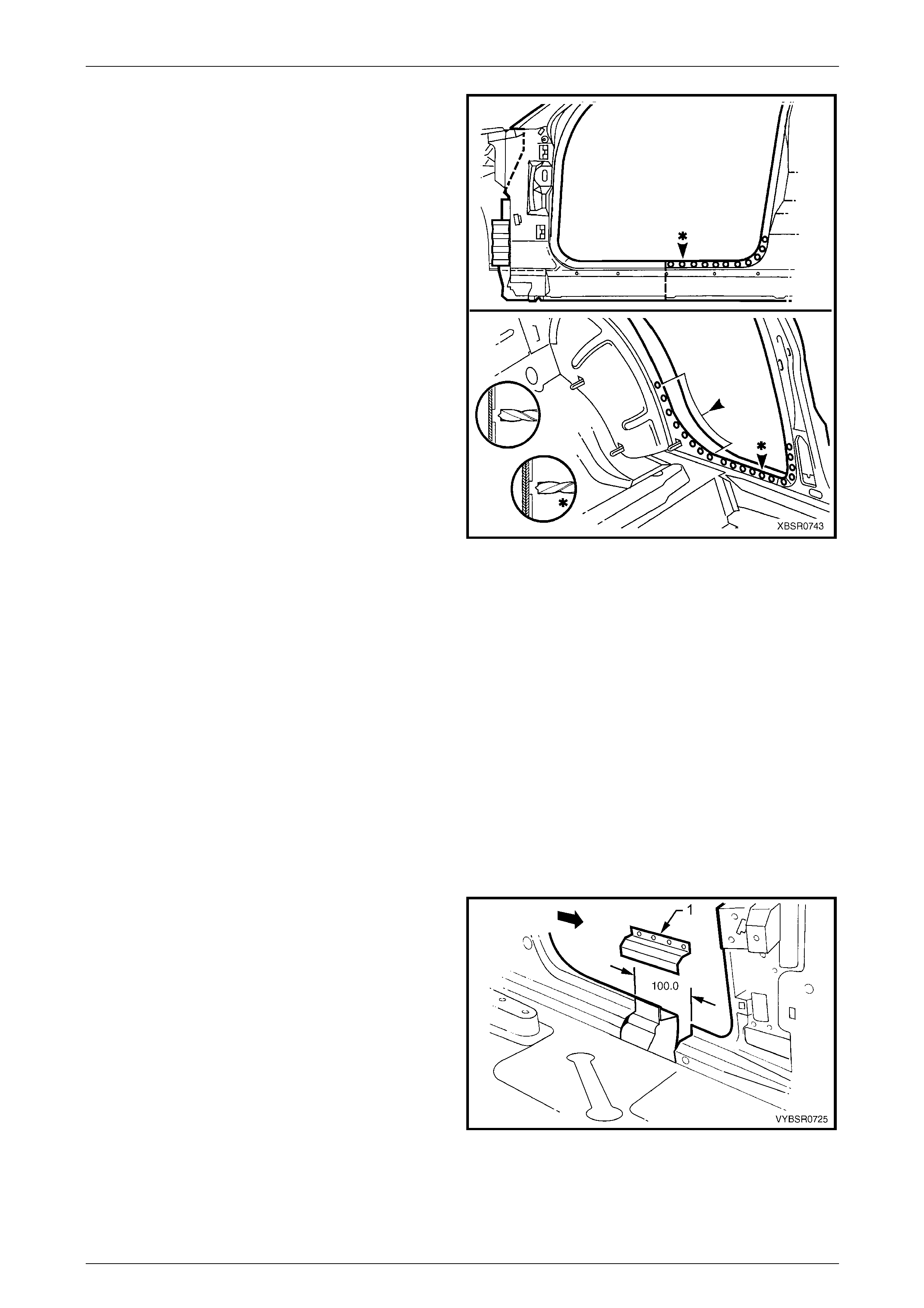
2 For the right-hand side, if required spot or plug weld
(1) the fuel filler pipe housing to the rear quarter panel
in four places.
3 As required, mark the new panel with drilling locations
in preparation for plug welding. Drill holes as required.
4 Prepare all mating surfaces and treat with Weld
Through Primer (Item 1) as required,
refer to Section 3B Body Construction – Wagon.
5 Apply Acrylic Spot Weld Sealer (Item 2),
refer to Section 3B Body Construction – Wagon.
6 Clamp the new panel in position on the vehicle and
test fit the alignment with the rear door and liftgate. Figure 7B – 7
7B Body Side – Wagon Page 7B-8
Page 7B-8
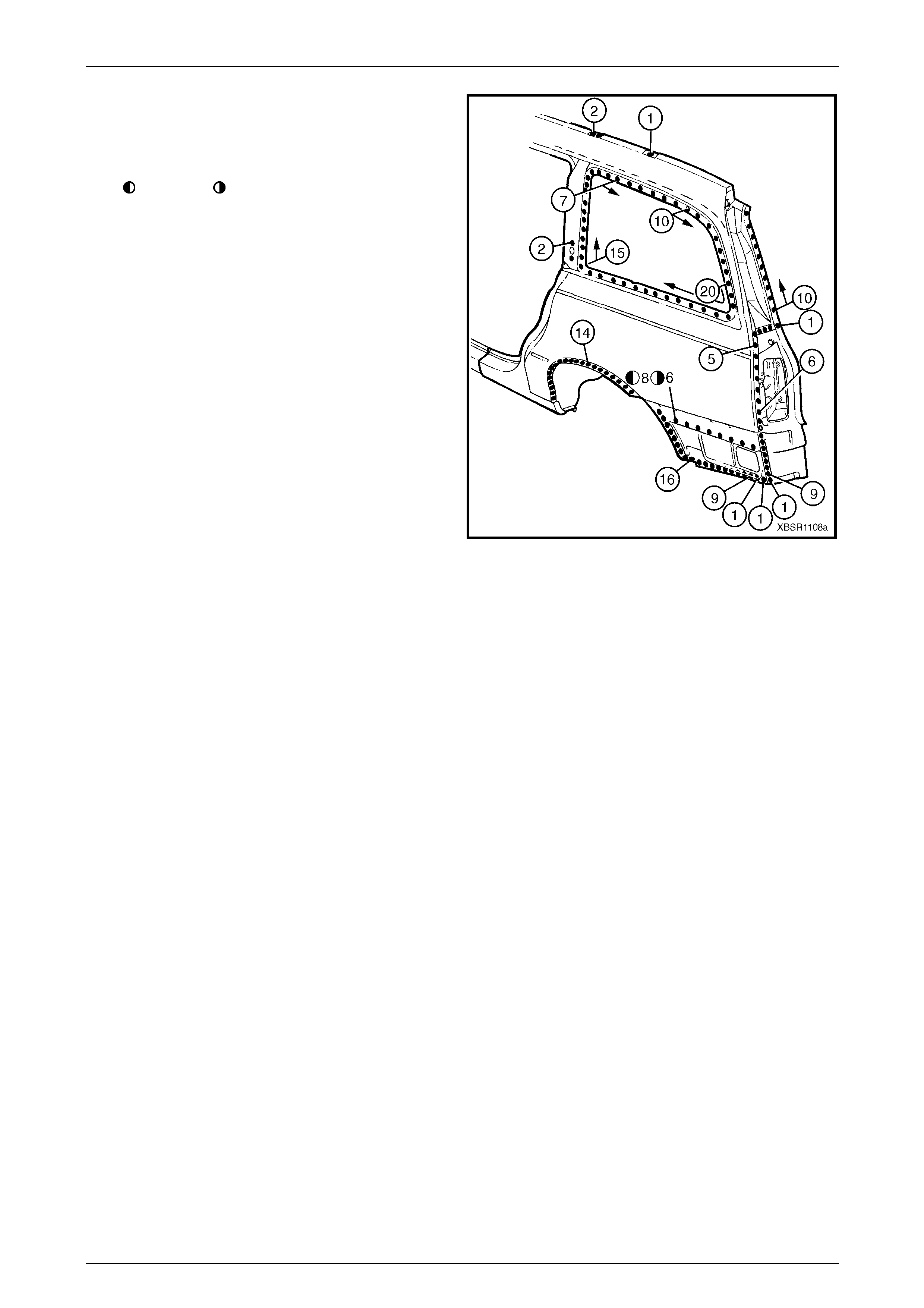
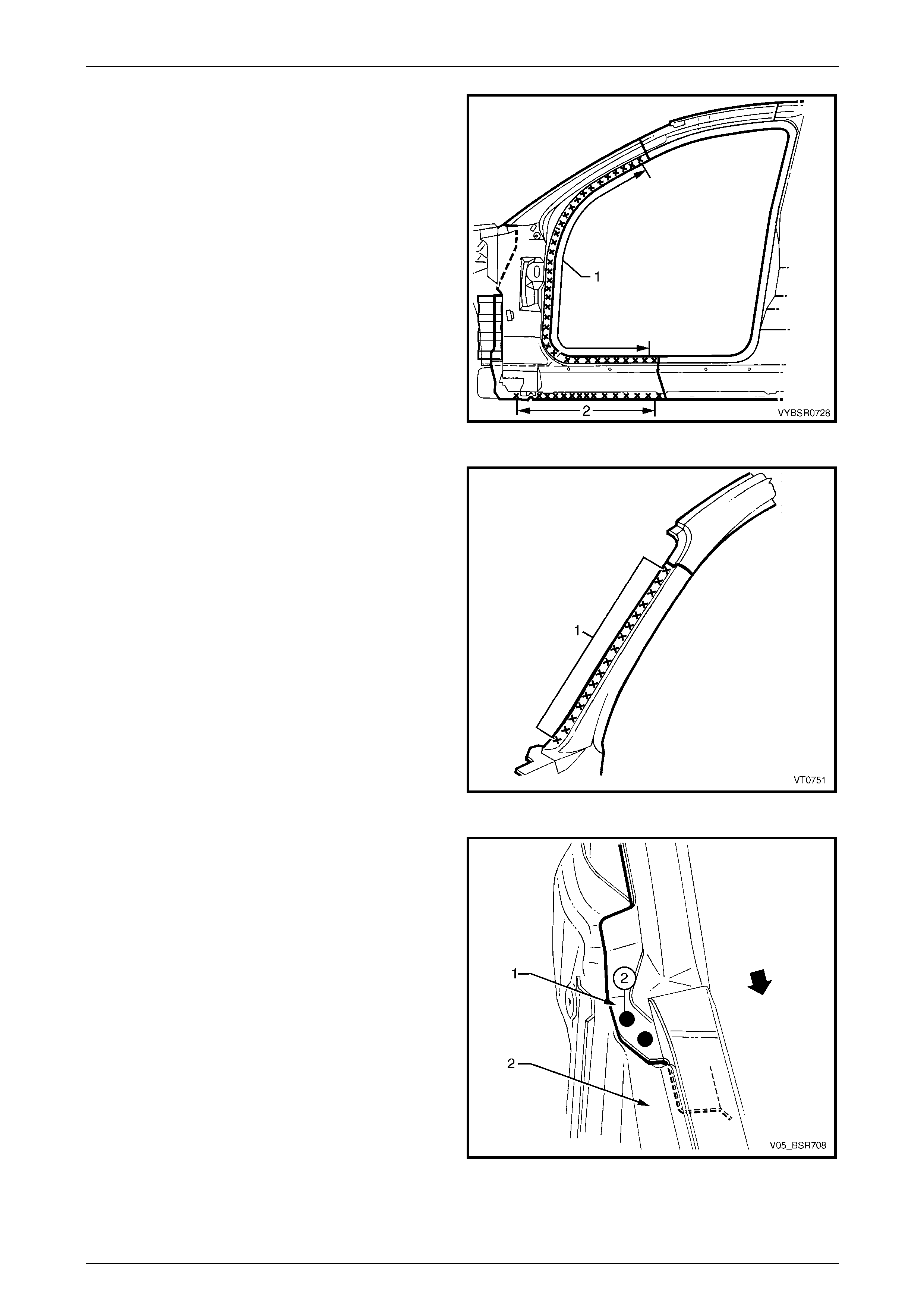
7 MIG butt weld across the panel joins if a partial pane l
replacement was performed.
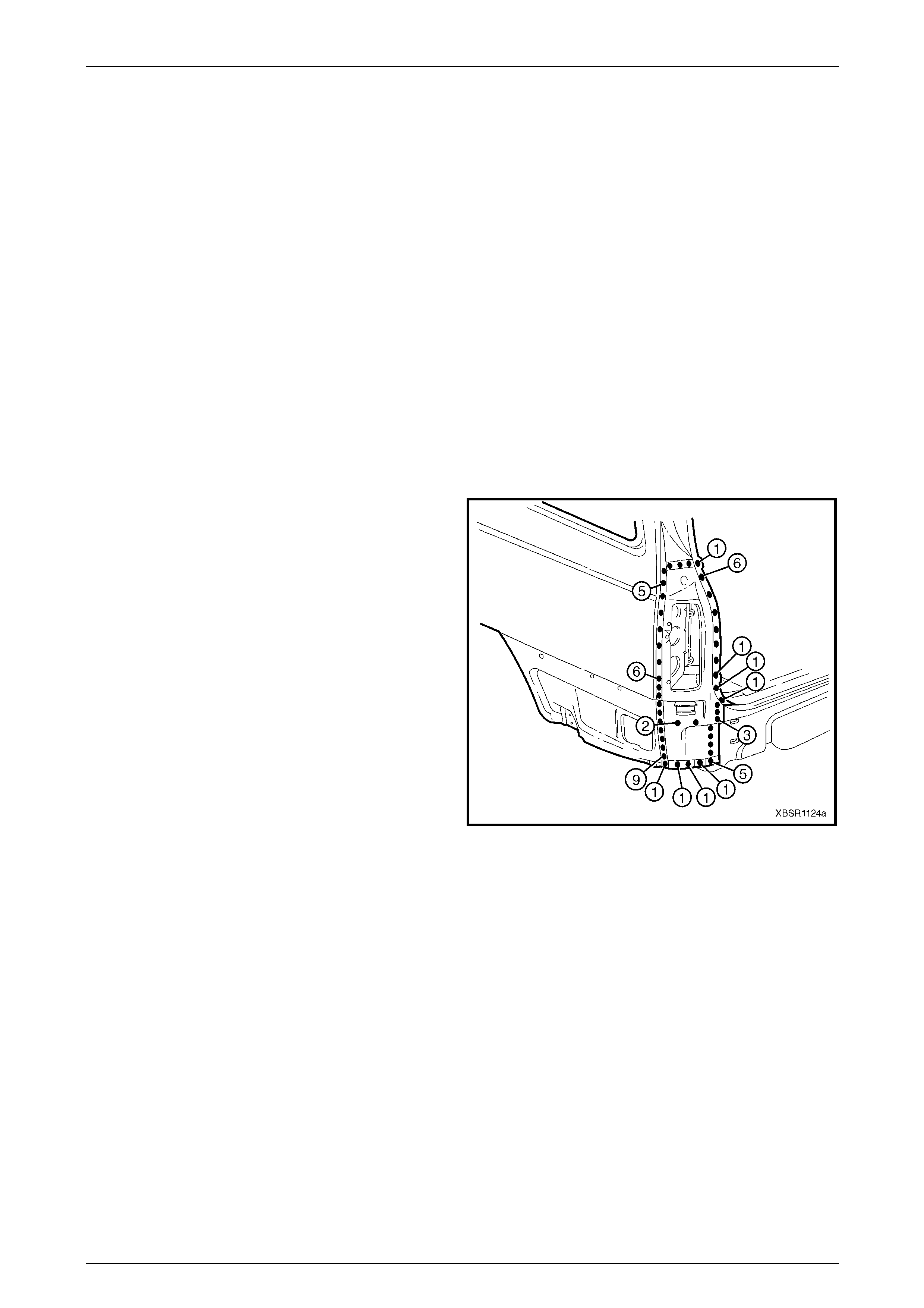
Figure 7B – 8
8 Spot or plug weld the rear quarter panel ar ound the
door opening and rocker pane l.
Figure 7B – 9
7B Body Side – Wagon Page 7B-9
Page 7B-9
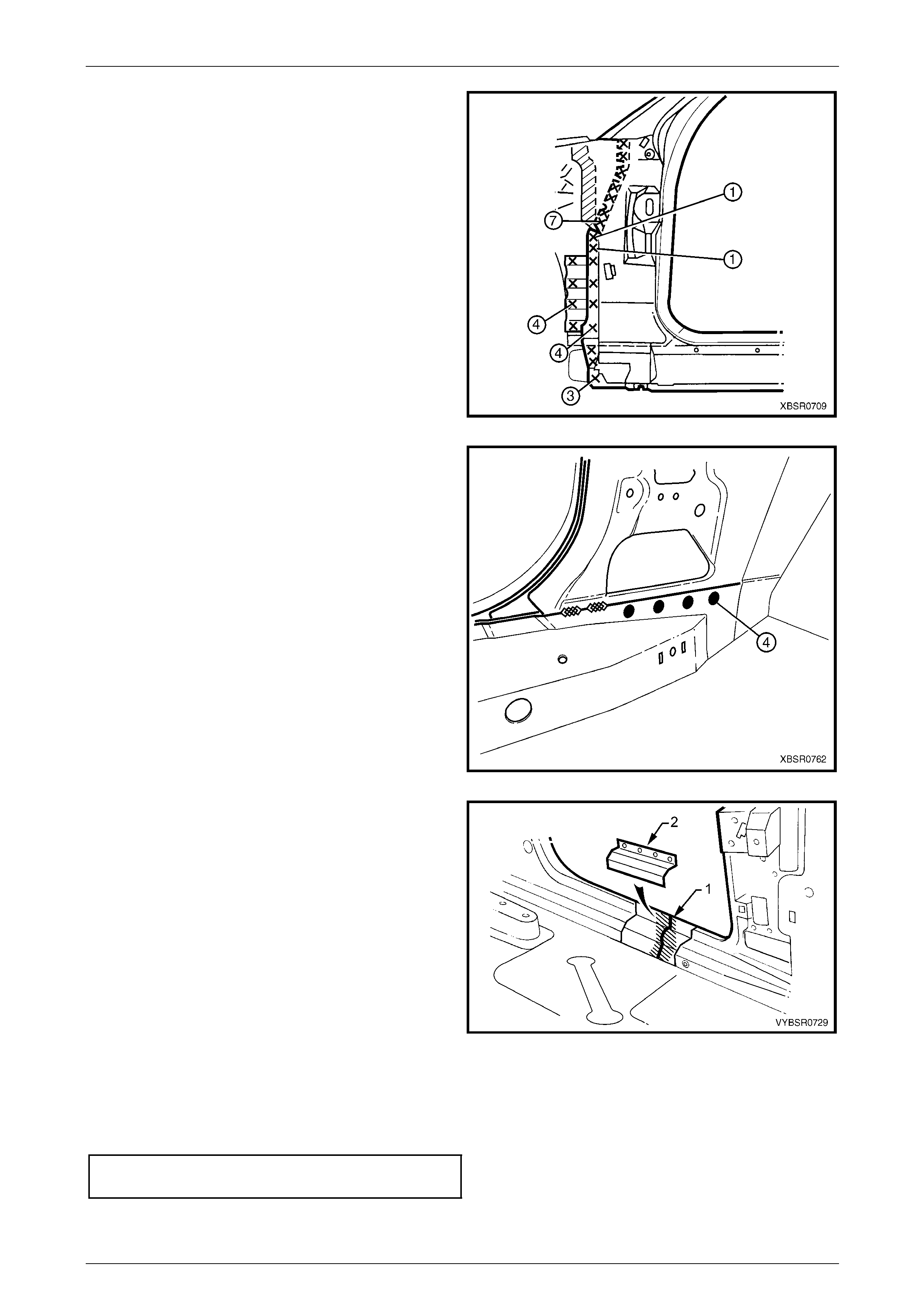
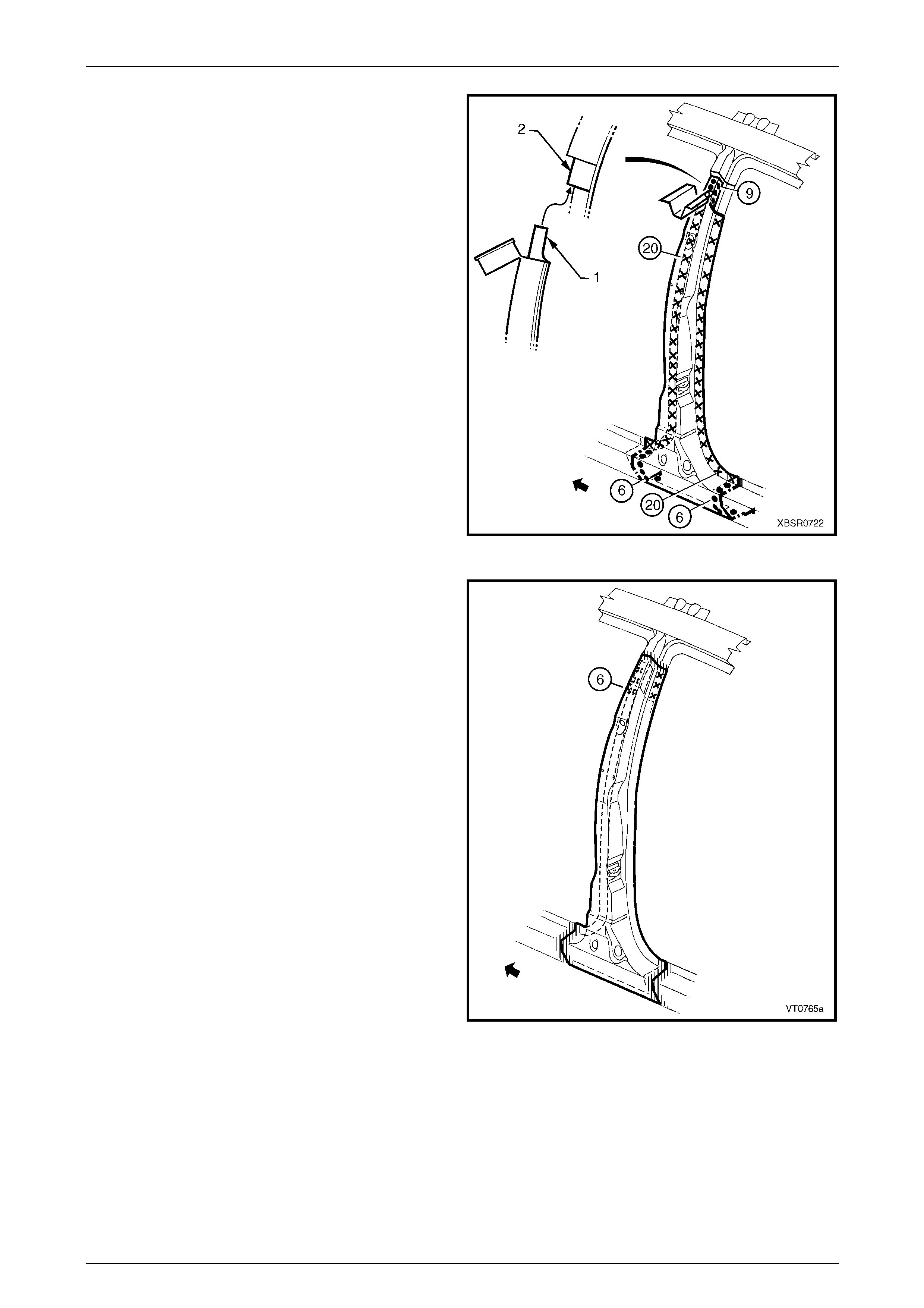
9 Spot or plug weld the rear quarter panel to the quarter
panel inner assembly, quarter outer lower rear panel
and the quarter panel e xtens ion if still installed.
NOTE
= left-hand, = right-hand
10 If removed, install the quarter pan el extension,
refer to 2.2 Quarter Panel Extension – Replace.
11 If a partial replacement was performed, grind or sand
the lock and back pillar butt welds to achieve a smooth
finish ensuring that too much material is not removed.
12 Refinish and paint panels and other components as
required. Refer to Section 3 Body Construction .
13 Apply Joint Sealer (Item 3) as required.
Refer to Section 3B Body Construction – Wagon.
14 Apply Cavity Wax (Item 8) as required to the inside of
any box sections or areas inaccessible to paint,
refer to Section 3B Body Construction – Wagon.
15 Replace the Stuffer Block between the side pan el -
inner and the rear quarter panel.
Refer to Section 3B Body Construction – Wagon.
16 Install the quarter window assembly, refer to
Section 1A6 Stationary Windows in the MY2005 VZ
Service Information
17 Install the remaining components as described in the
MY2005 VZ Service Information.
Figure 7B – 10
7B Body Side – Wagon Page 7B-10
Page 7B-10
2.2 Quarter Panel Extension – Replace
To avoid the possibility of fire, take particular
care when cuttin g or w elding at the r ear of th e
vehicle. Remove the fuel tank and plug the
fuel lines.
Remove
1 Remove the adjacent bolt-on panels a nd components
as described in the appropriate Section of the MY2005
VZ Service Information.
2 Remove the rear bumper impact bar,
refer to Section 3 Body Construction.
Figure 7B – 11
3 Spot cut the welds attaching the quarter panel
extension to the rear quarter panel, the quarter outer
lower rear panel and the quar ter panel inner assembly.
4 Remove the panel from the vehicle, then repair any
damage to adjacent parts as required.
5 Check and rectify the alignme nt of
the body as requir ed,
refer to Section 3B Body Construction – Wagon.
Figure 7B – 12
7B Body Side – Wagon Page 7B-11
Page 7B-11
Replace
NOTE
• Spot welding is the preferred method for
attaching of panels and should be used
whenever possible. Where the spot welding
equipment available will not access the
required weld position, a plug weld should be
performed.
• The same number and position of spot welds
(or plug welds) should be used when
replacing the panel, as was used during
manufacture, in order to maintain the original
structural strength of the vehicle.
1 As required, mark the new panel with drilling locations in preparation for plug welding. Drill holes as required.
2 Prepare all mating surfaces and treat with Weld Through Primer (Item 1) as requir ed,
refer to Section 3B Body Construction – Wagon.
3 Tack weld the quarter panel extension in position and install the tail lamp to check for correct location and
alignment. Adjust the position of the quarter panel e xtension as required.
4 Spot or plug weld the quarter panel e xtension in place.
5 Refinish and paint panels and other components as
required. Refer to Section 3 Body Construction .
6 Apply Joint Sealer (Item 3) as required.
Refer to Section 3B Body Construction – Wagon.
7 Apply Cavity Wax (Item 8) as required to the inside of
any box sections or areas inaccessible to paint,
refer to Section 3B Body Construction – Wagon.
8 Install the rear bumper impact bar,
refer to Section 3 Body Construction.
9 Install the remaining components as described in the
MY2005 VZ Service Information.
Figure 7B – 13
7B Body Side – Wagon Page 7B-12
Page 7B-12
2.3 Quarter Panel Inner Lower Rear
Extension – Replace
Remove
1 Remove the adjacent bolt-on panels a nd components
as described in the appropriate Section of the MY2005
VZ Service Information.
2 Remove the quarter panel extension and any other
adjoining panel s as required, refer to the appropriate
procedure in this Section.
Figure 7B – 14
3 Spot cut the welds attaching the quarter panel inner
lower rear extension to the quarter panel inner, rear
quarter panel and rear end pa nel extension as
required.
4 Remove the panel from the vehicle, and then repa ir
any damage to adjacent parts as required.
Figure 7B – 15
7B Body Side – Wagon Page 7B-13
Page 7B-13
Replace
NOTE
• Spot welding is the preferred method for
attaching of panels and should be used
whenever possible. Where the spot welding
equipment available will not access the
required weld position, a plug weld should be
performed.
• The same number and position of spot welds
(or plug welds) should be used when
replacing the panel, as was used during
manufacture, in order to maintain the original
structural strength of the vehicle.
1 As required, mark the new panel with drilling locations in preparation for plug welding. Drill holes as required.
2 Prepare all mating surfaces and treat with Weld Through Primer (Item 1) as requir ed,
refer to Section 3B Body Construction – Wagon.
3 Clamp the quarter panel inner lower rear extension in
position on the vehicle and spot or plug weld to the
quarter panel inner assembly, rear quarter and rear
end panel extension as required.
4 Replace any removed panels as required, refer to the
appropriate procedure in this Section.
5 Refinish and paint panels and other components as
required. Refer to Section 3 Body Construction .
6 Apply Joint Sealer (Item 3) as required.
Refer to Section 3B Body Construction – Wagon.
7 Apply Cavity Wax (Item 8) as required to the inside of
any box sections or areas inaccessible to paint,
refer to Section 3B Body Construction – Wagon.
8 Install the remaining components as described in the
MY2005 VZ Service Information.
Figure 7B – 16
7B Body Side – Wagon Page 7B-14
Page 7B-14
2.4 Quarter Outer Lower Rear Panel –
Replace
To avoid the possibility of fire, take particular
care when cuttin g or w elding at the r ear of th e
vehicle. Remove the fuel tank and plug the
fuel lines.
Remove
1 Remove the adjacent bolt-on panels a nd components
as described in the appropriate Section of the MY2005
VZ Service Information.
Figure 7B – 17
2 Spot cut the welds attaching the quarter panel outer
lower rear panel to the rear quarter panel an d quarter
panel inner assembly as required.
NOTE
• = left-hand, = right-hand
3 Remove the panel from the vehicle, and then repa ir
any damage to adjacent parts as required.
Figure 7B – 18
7B Body Side – Wagon Page 7B-15
Page 7B-15
Replace
NOTE
• Spot welding is the preferred method for
attaching of panels and should be used
whenever possible. Where the spot welding
equipment available will not access the
required weld position, a plug weld should be
performed.
• The same number and position of spot welds
(or plug welds) should be used when
replacing the panel, as was used during
manufacture, in order to maintain the original
structural strength of the vehicle.
1 As required, mark the new panel with drilling locations in preparation for plug welding. Drill holes as required.
2 Prepare all mating surfaces and treat with Weld Through Primer (Item 1) as requir ed,
refer to Section 3B Body Construction – Wagon.
3 Spot or plug weld the quarter panel o uter lower rear
panel to the rear quarter panel and quarter panel inner
assembly as required.
NOTE
• = left-hand, = right-hand
4 Replace any removed panels as required, refer to the
appropriate procedure in this Section.
5 Refinish and paint panels and other components as
required. Refer to Section 3 Body Construction .
6 Apply Joint Sealer (Item 3) as required.
Refer to Section 3B Body Construction – Wagon.
7 Apply Cavity Wax (Item 8) as required to the inside of
any box sections or areas inaccessible to paint,
refer to Section 3B Body Construction – Wagon.
8 Install the remaining components as described in the
MY2005 VZ Service Information. Figure 7B – 19
7B Body Side – Wagon Page 7B-16
Page 7B-16
2.5 Door Opening Frame Assembly –
Replace
Remove
NOTE
• This procedure requires the removal of the
roof panel. As an alternative, the door
opening frame assembly can be cut at the
upper pillar sections by following the
procedures in 2.6 Door Opening Frame
Assembly – Partial Replace, Hinge Pillar,
2.7 Door Opening Frame Assembly – Partial
Replace. Centre Pillar and
2.8 Door Opening Frame Assembly – Partial
Replace, Lock Pillar.
• Cavity Foam is used within the hinge, centre
and lock pillar cavities. Care is required when
repairing the vehicle in these areas, refer to
Section 2 Precautions prior to beginning any
work for further information.
1 Remove the adjacent bolt-on panels a nd components
as described in the appropriate Service Information.
2 Remove the windshield and the rear window
assemblies, refer to Section 1A6 Stationary Windows
in the MY2005 VZ Service Information.
3 Remove the dash panel retaining bolt from the hinge
pillar.
4 Remove the roof panel, refer to Section 9B Roof.
5 Remove the rear quarter panel,
refer to 2.1 Rear Quarter Panel – Replace.
6 Remove the front wheelhouse pan el upper side rail,
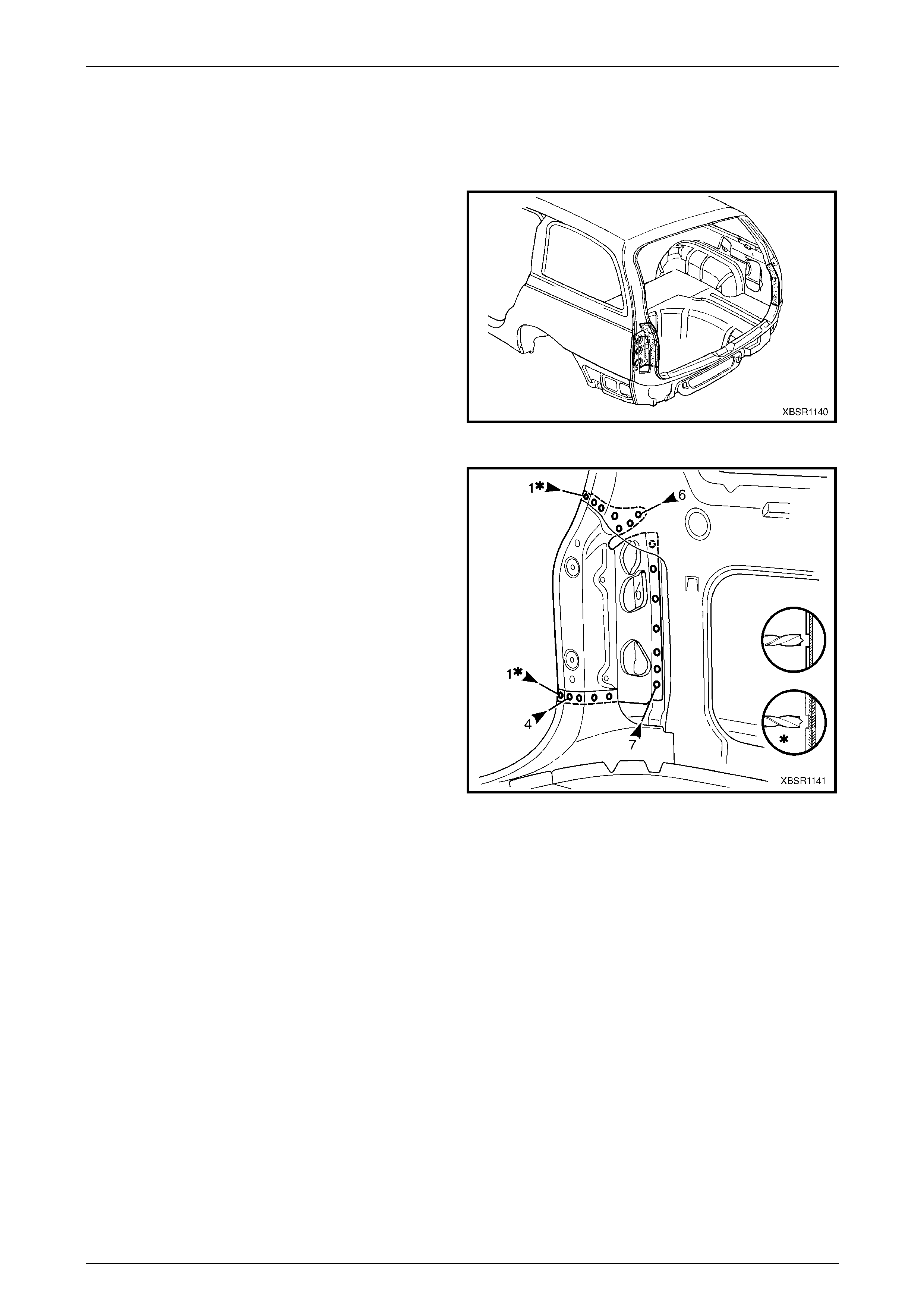
refer to Section 4 Front End. Figure 7B – 20
7 Spot cut the welds attaching the door openin g frame
assembly to the inner rocker panel and to the hin ge
pillar inner panel assembly.
NOTE
In order to spot cut the uppermost of these welds
it may be necessary to cut and peel back the
section of hinge reinforcement panel covering
the welds, to gain the required access.
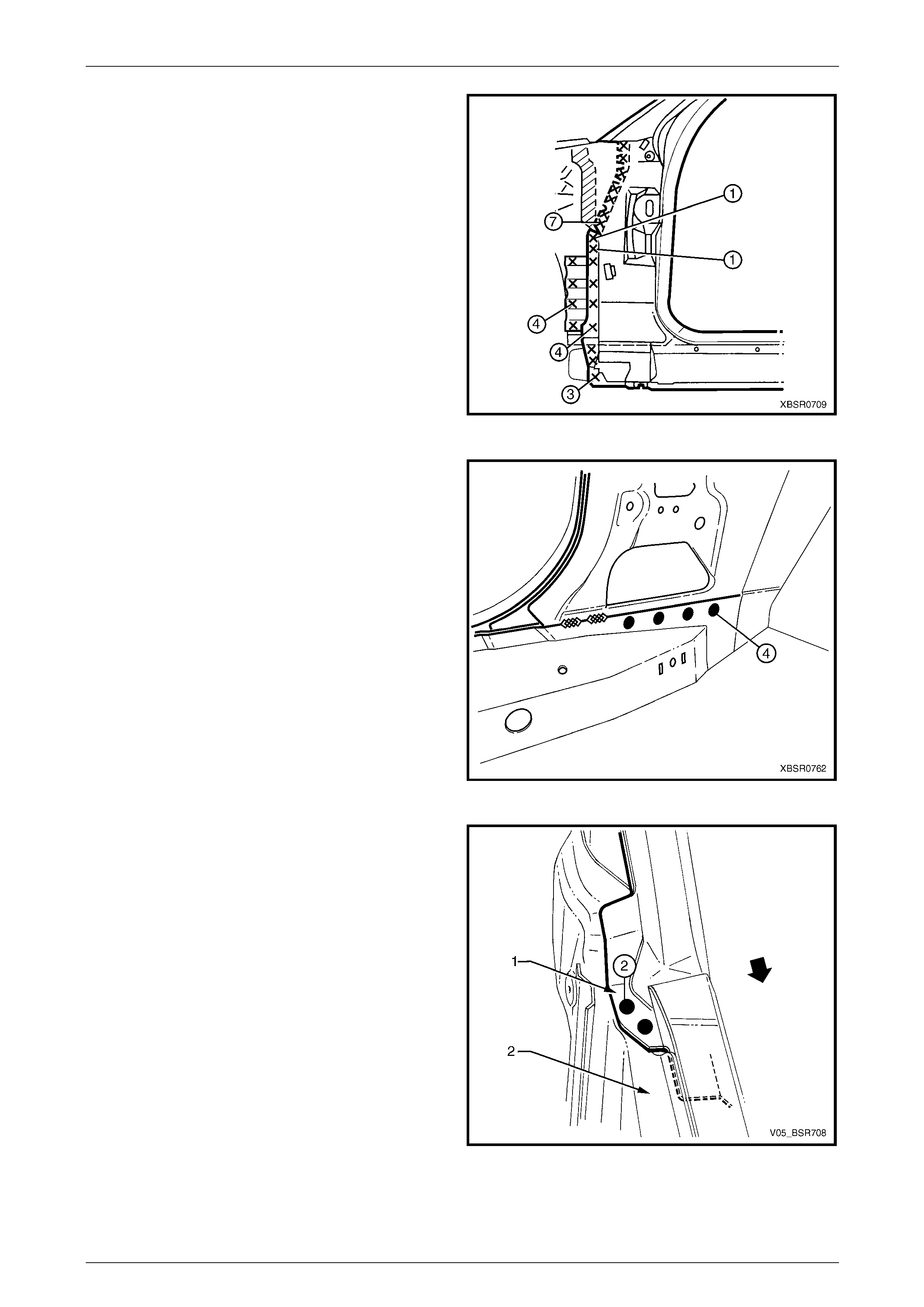
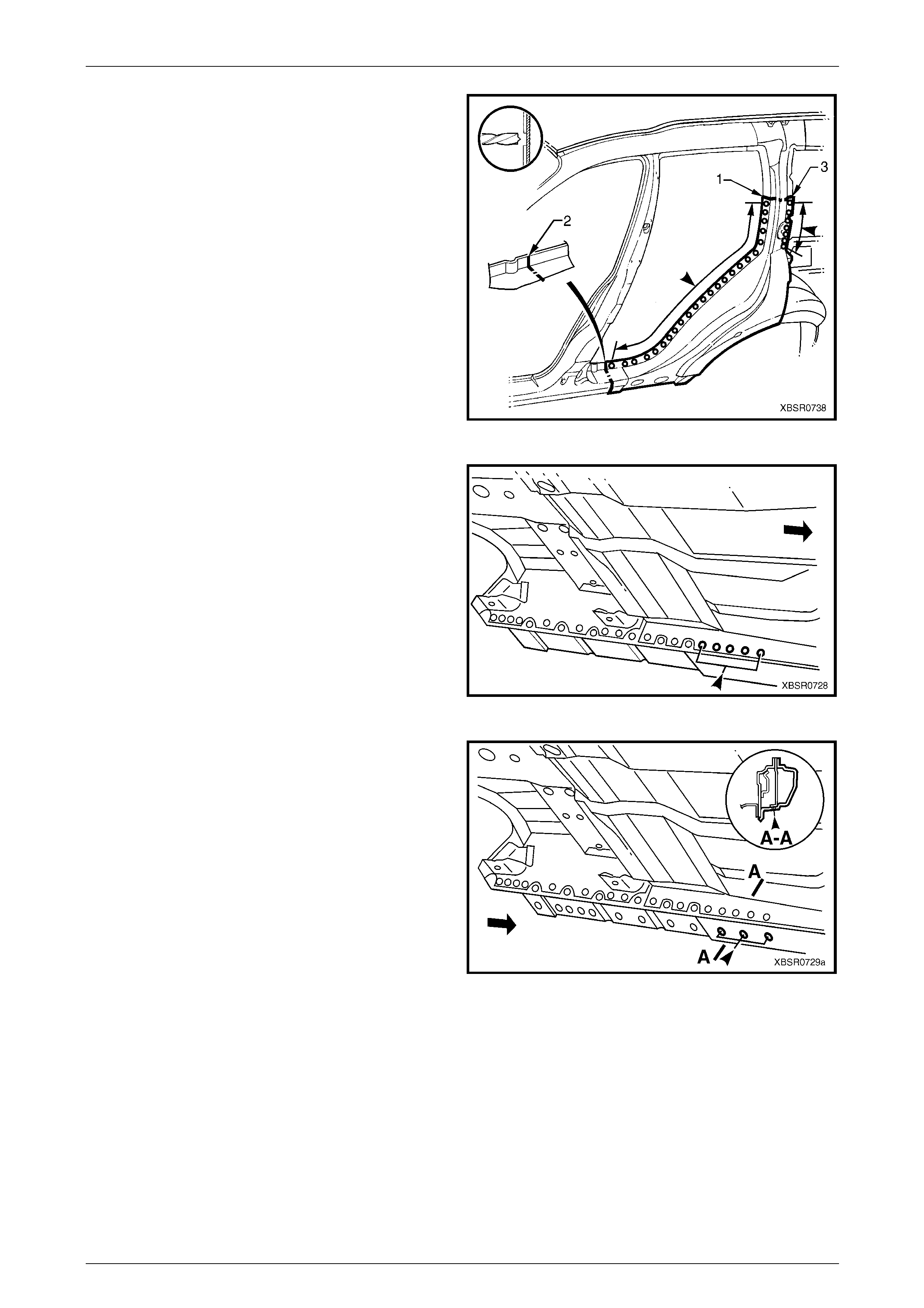
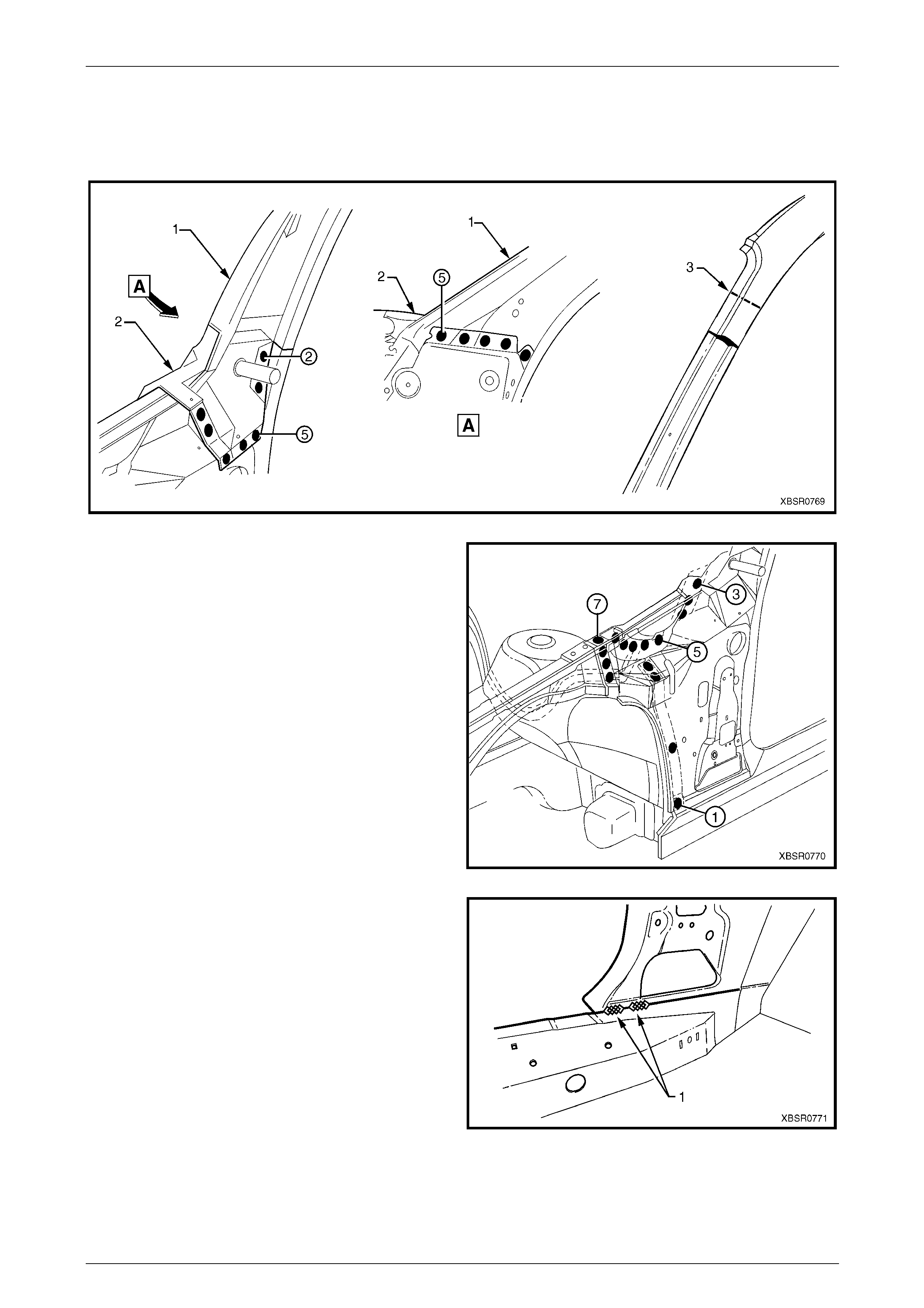
8 Spot cut the welds attaching the inner rocker panel (1)
and hinge pillar inner p an el assembly (2) to the rocker
panel reinforcement (3). Refer to Figure 7B – 22.
NOTE
It is not required to cut the MIG welds.
Figure 7B – 21
7B Body Side – Wagon Page 7B-17
Page 7B-17
Figure 7B – 22
9 Spot cut the two welds at the base of the hinge pillar,
attaching the door opening frame assembly (1) to the
hinge pillar inner panel assembly (2).
Figure 7B – 23
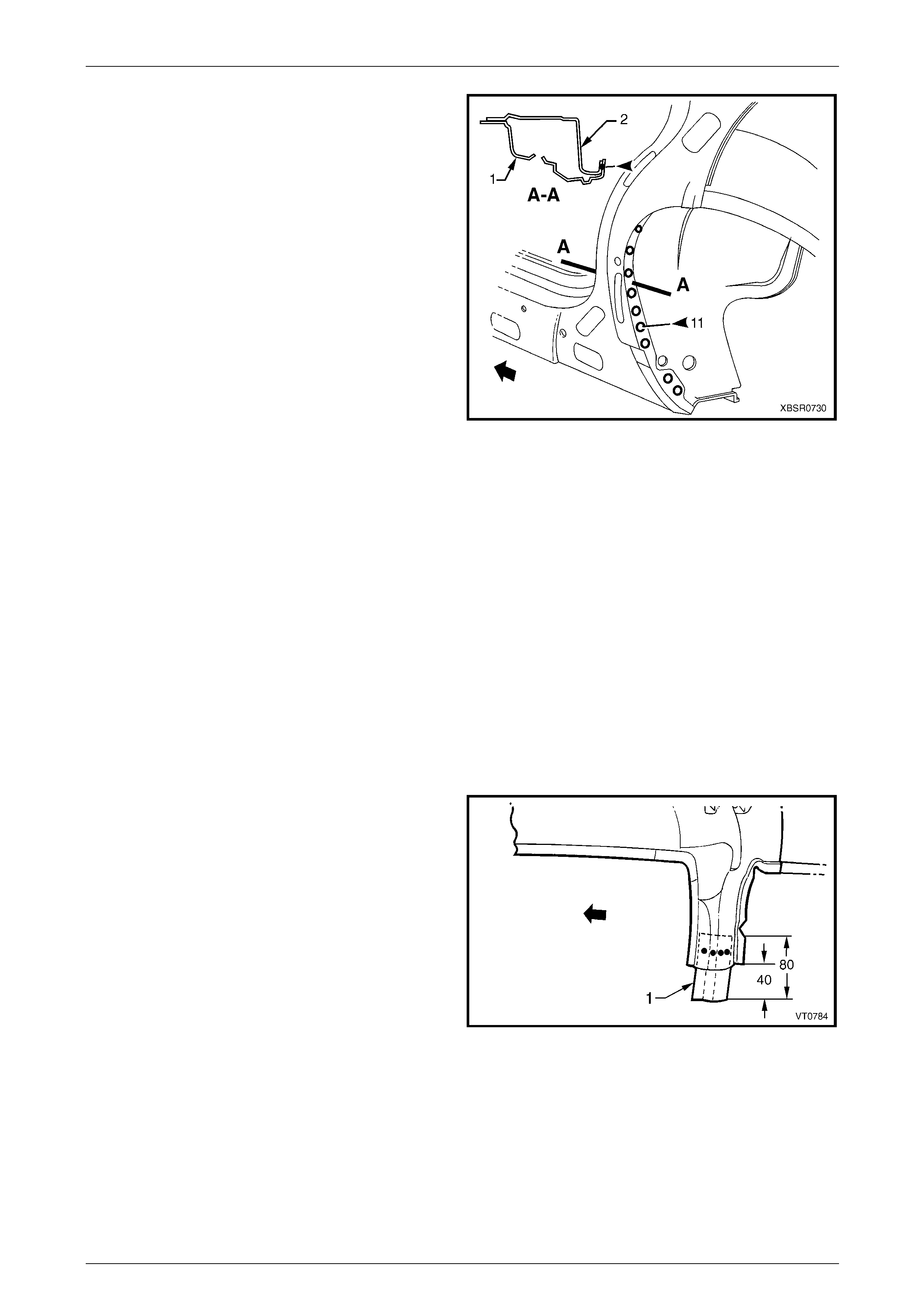
10 Spot cut the welds on the windshield side flange,
attaching the door opening frame assembly (1) to the
hinge pillar inner panel assembly (2).
Figure 7B – 24
7B Body Side – Wagon Page 7B-18
Page 7B-18
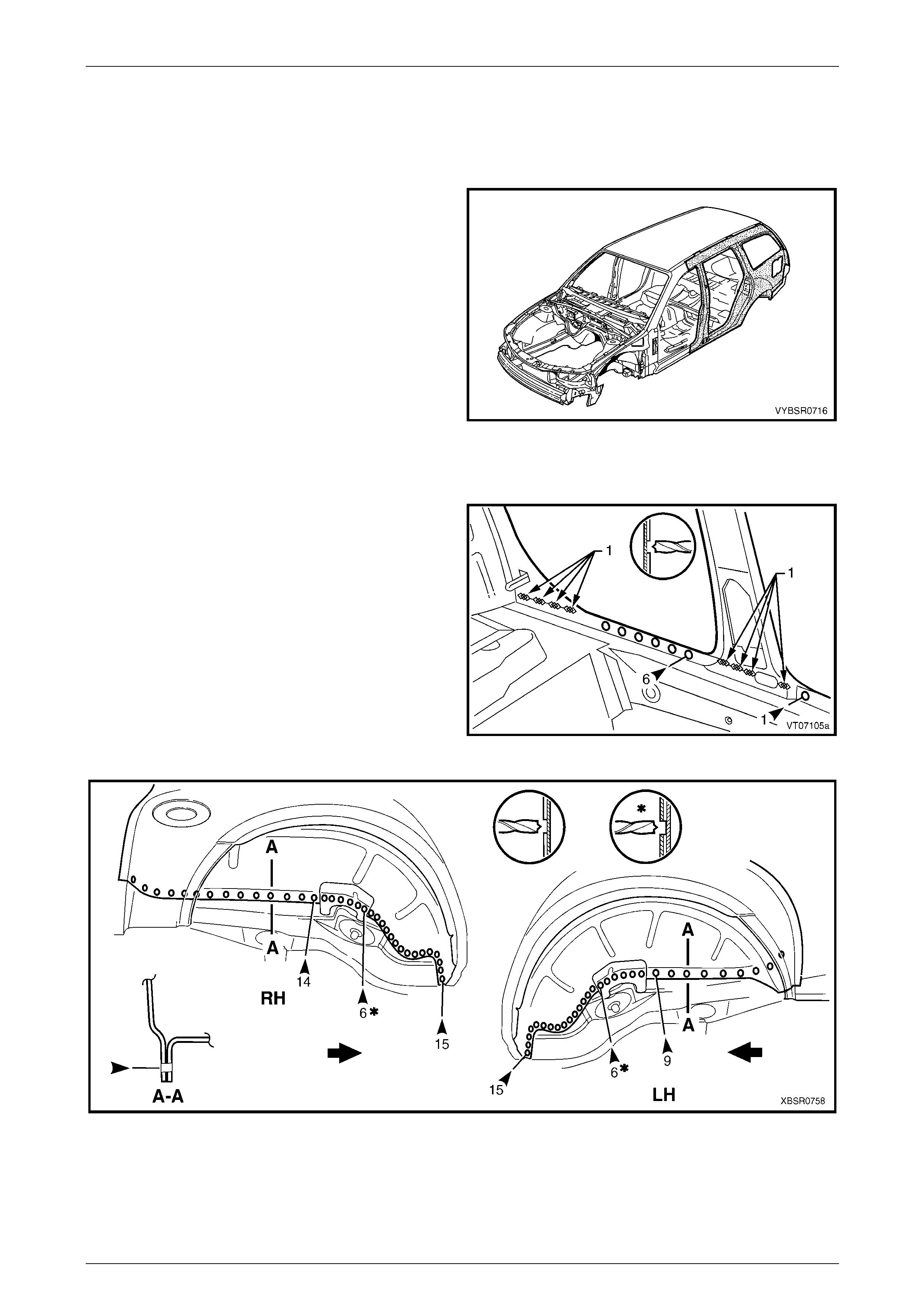
11 Spot cut the welds on the flange surrounding the front
door opening, attaching the door op ening frame
assembly to the hinge pillar inner pa nel assembly,
inner rocker panel and quarter panel inner assembly.
Figure 7B – 25
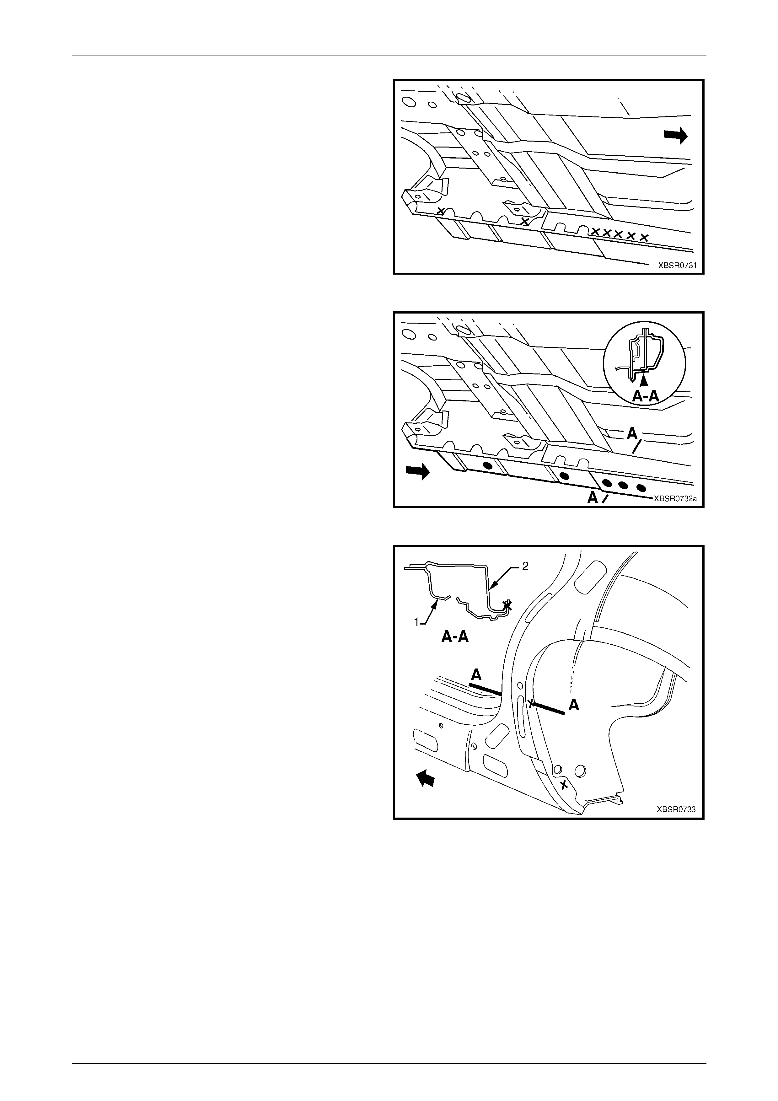
12 Spot cut the welds around the rear wheel arch joining
the door opening frame assembly (1) to the quarter
panel inner assembly (2).
NOTE
Many welds may have been removed with the
rear quarter panel.
13 Spot cut along the vertical flange below the rocker
panel to separate the door opening frame assembly
from the inner rocker panel and rear floor p an el outer
extension. Refer to F igure 7B – 27.
Figure 7B – 26
Figure 7B – 27
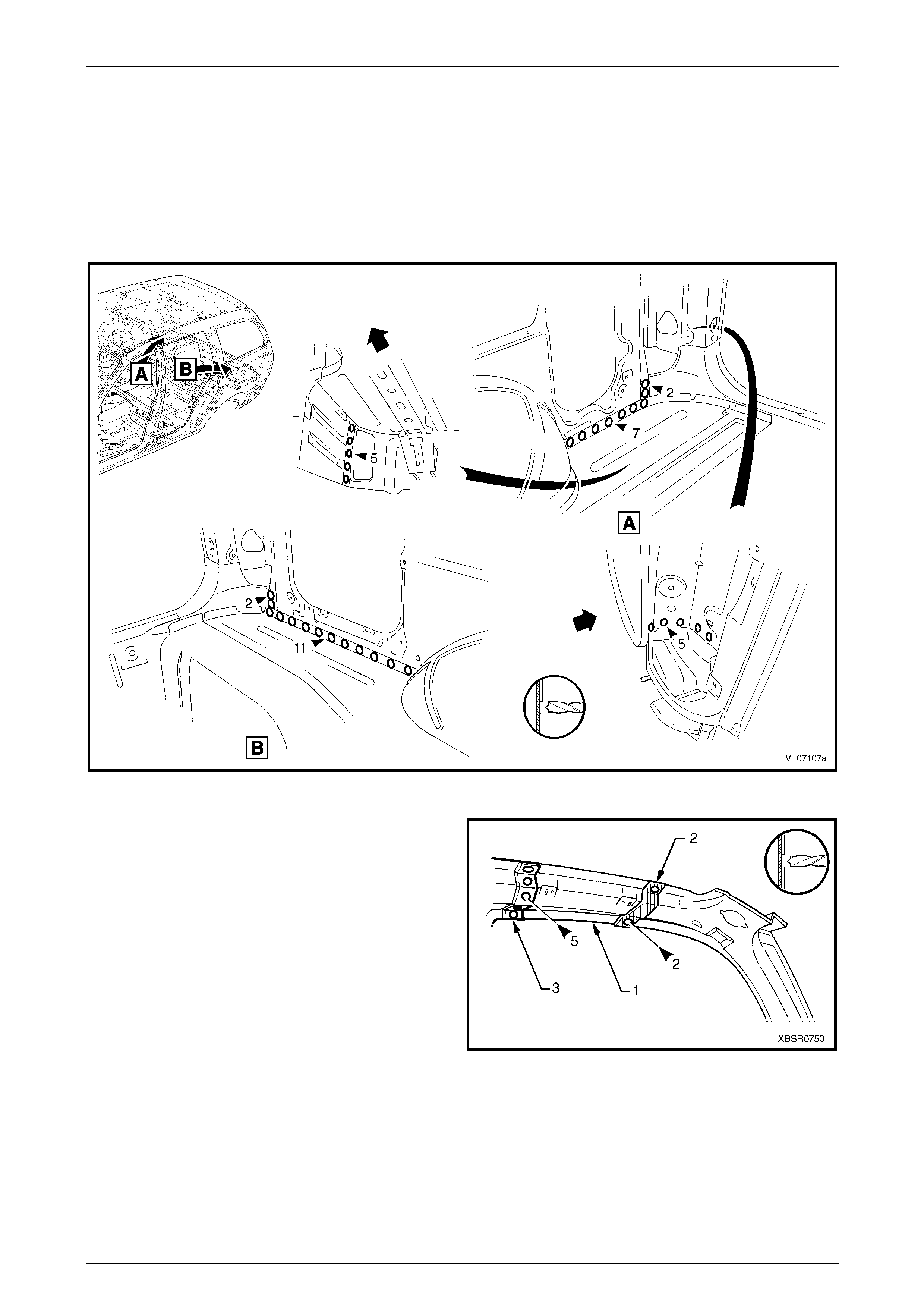
14 Spot cut from below, up into the rocker panel, the welds attaching the door opening frame assembly to the quarter
panel inner assembly, refer to Figure 7B – 28.
7B Body Side – Wagon Page 7B-19
Page 7B-19
Figure 7B – 28
15 Spot cut the welds on the rear door opening flang e,
attaching the door opening fram e assembly to the
quarter panel inner assembly.
NOTE
Some welds may have been removed with the
quarter panel.
Figure 7B – 29
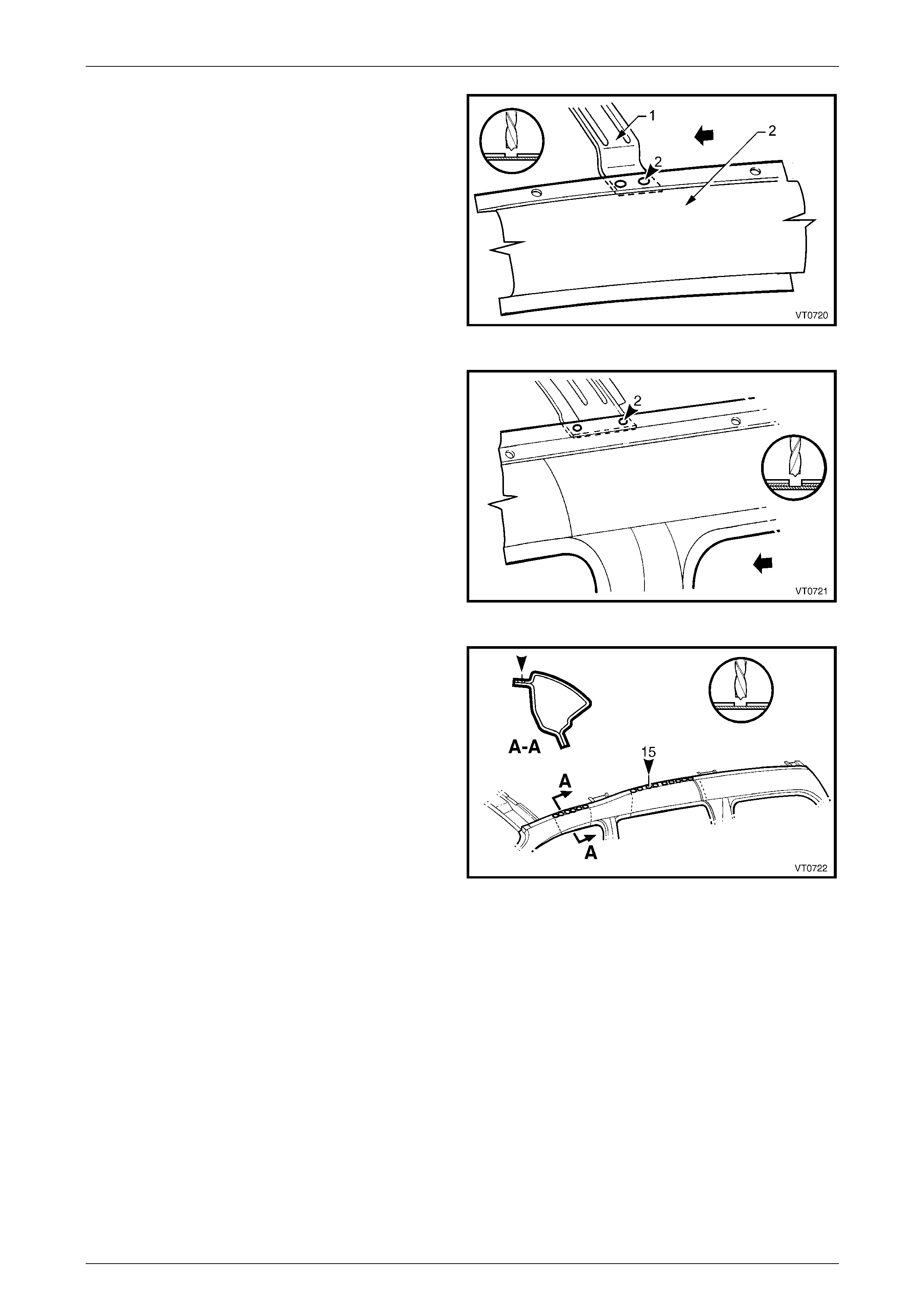
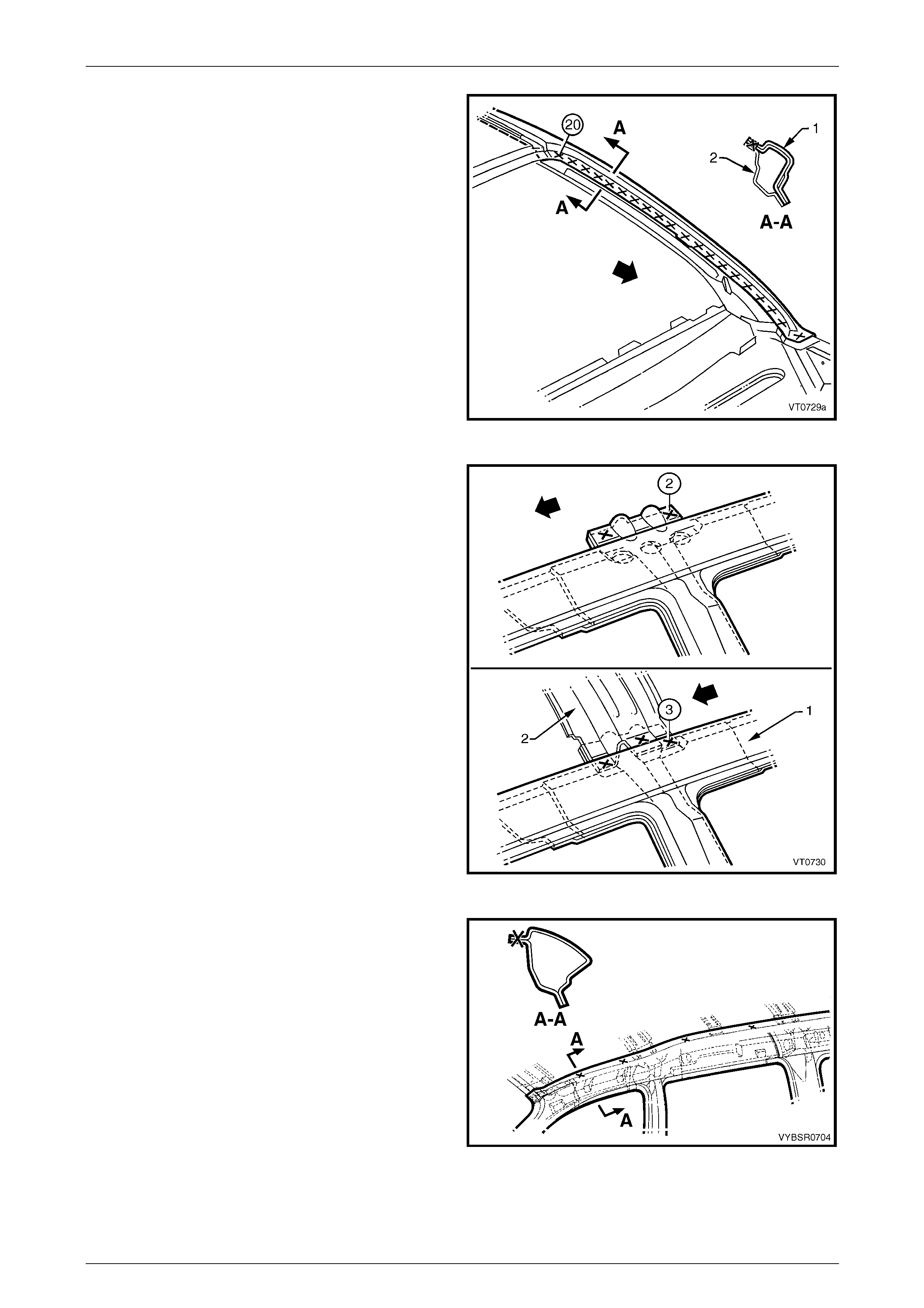
16 Spot cut the two welds attaching the roof bow panel
(2) to the centre pillar upper reinforcement, and the
single weld attaching the roof bow panel to the door
opening frame assembly (1).
Figure 7B – 30
7B Body Side – Wagon Page 7B-20
Page 7B-20
17 Spot cut the two welds attaching roof bow panel No. 2
(1) to the door opening frame assembly (2).
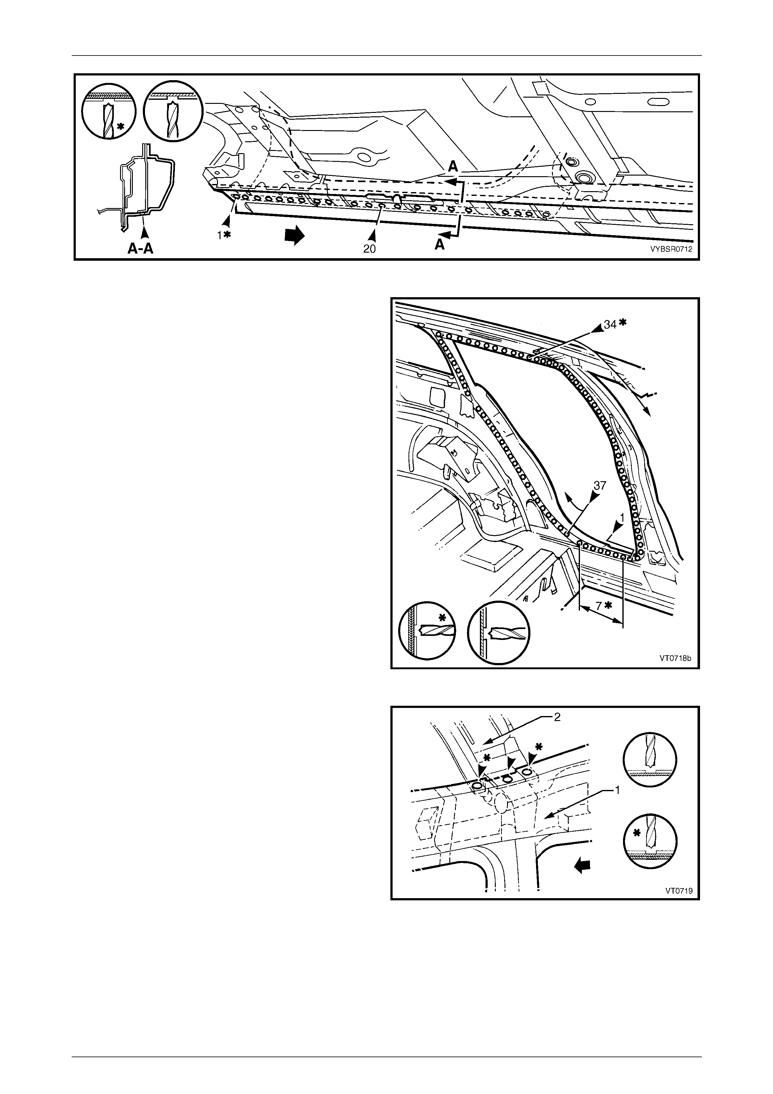
Figure 7B – 31
18 Spot cut the two welds attaching the roof bow panel
No. 3 to the door opening frame assembly and the
quarter panel inner assembly.
Figure 7B – 32
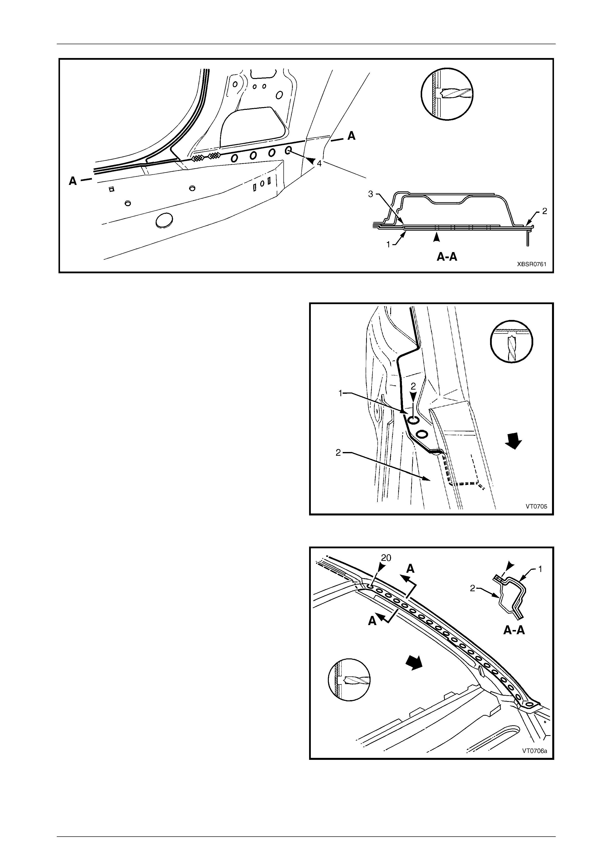
19 Spot cut the welds along the roof attachment flange.
NOTE
Many welds may have been removed with the
roof panel.
20 Remove the complete door opening frame assembly
and repair any dama ge to adjacent parts.
21 Check and rectify the alignme nt of
the body shell as required,
refer to Section 3B Body Construction – Wagon.
Figure 7B – 33
7B Body Side – Wagon Page 7B-21
Page 7B-21
Replace
NOTE
• Spot welding is the preferred method for
attaching of panels and should be used
whenever possible. Where the spot welding
equipment available will not access the
required weld position, a plug weld should be
performed.
• The same number and position of spot welds
(or plug welds) should be used when
replacing the panel, as was used during
manufacture, in order to maintain the original
structural strength of the vehicle.
1 As required, mark the new panel with drilling locations in preparation for plug welding. Drill holes as required.
2 Prepare all mating surfaces and treat with Weld Through Primer (Item 1) as requir ed,
refer to Section 3B Body Construction – Wagon.
3 Apply Acrylic Spot Weld Sealer (Item 2), refer to Section 3B Body Construction – Wagon.
4 Securely clamp the door openin g frame assembly in
position on the vehicle body.
5 Begin attaching the door opening frame assembly by
spot welding around the front door opening flange.
Figure 7B – 34
7B Body Side – Wagon Page 7B-22
Page 7B-22
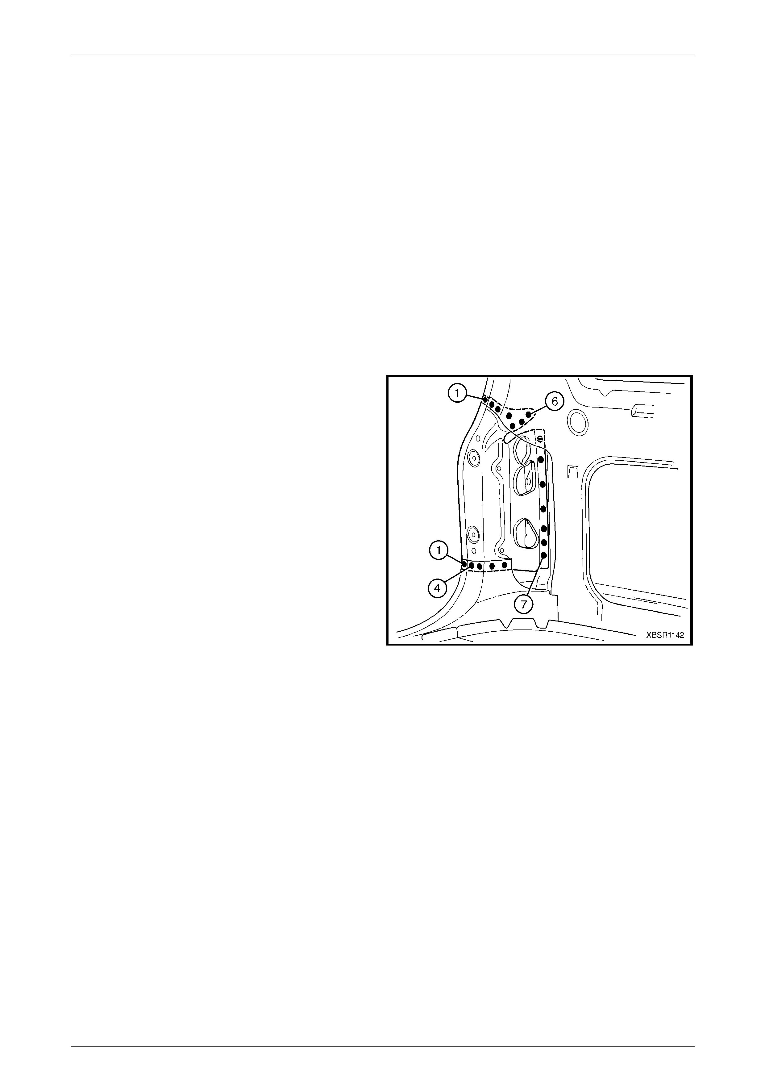
6 Spot weld around the flange of the rear door opening.
Figure 7B – 35
7 Spot or plug weld in two places arou nd the rear wheel
arch, attaching the door opening frame assembly to
the quarter panel inner assembl y.
NOTE
These welds will be completed when the rear
quarter panel is replaced.
Figure 7B – 36
7B Body Side – Wagon Page 7B-23
Page 7B-23
8 Spot or plug weld the door opening frame assembly to
the inner rocker panel and to the hinge pillar inner
panel assembly. If the sheetmetal was modified to
allow access to these welds, it should be repaired to
its original configuration.
Figure 7B – 37
9 Plug weld the inner rocker pa nel and hinge pillar inner
panel assembly to the rocker panel reinforcement.
Figure 7B – 38
10 Spot or plug weld the door opening frame assembly
(1) to the hinge pillar inner panel assembly (2) at the
base of the hinge pillar.
Figure 7B – 39
7B Body Side – Wagon Page 7B-24
Page 7B-24
11 Spot or plug weld the rear windo w flange to the door
opening frame assembly (1) and qu arter panel inner
assembly (2).
Figure 7B – 40
12 Spot or plug weld the door opening frame assembly
(1) to the quarter inner panel assemb ly, then spot or
plug weld the roof bow panel (2) to the door opening
frame assembly as shown.
Figure 7B – 41
13 Spot or plug weld the door opening frame assembly to
the quarter inner panel assembly along the roof panel
flange. Complete this flange when installing the roof
panel.
14 Spot or plug weld the door opening frame al ong the
vertical flange below the rocker panel,
refer to Figure 7B – 43.
Figure 7B – 42
7B Body Side – Wagon Page 7B-25
Page 7B-25
Figure 7B – 43
15 Plug weld up through the rocker panel to attach the door opening frame assembly to the quarter p anel inner
assembly. Refer to Figure 7B – 44.
NOTE
Leave some welds to until the rear quarter panel
is installed.
Figure 7B – 44
16 Replace front wheelhous e panel upper side rail, refer to Section 4 Front End.
17 Replace the rear quarter panel, refer to 2.1 Rear Quarter Pane l – Replace.
18 Replace the roof panel, refer to Section 9B Roof.
NOTE
Refinish and prime any bare metal as required
prior to replacing these panel s.
19 Install the door hinges, refer to Section 8 Do ors, Liftgate and Endgate.
20 Refinish and paint panels and other components as required. Refer to Section 3 Body Construction.
21 Apply Joint Sealer (Item 3) as required. Refer to Section 3B Body Construction – Wagon.
22 Apply Cavity Wax (Item 8) as required to the inside of any box secti ons or areas inaccessible to paint,
refer to Section 3B Body Construction – Wagon.
23 Apply Spray-on Dea dener (Item 7) where applicab le, refer to Section 3B Body Construc tion – Wagon.
24 Install the dash panel retaining bolt throu gh the hinge pil lar and tighten to the specified torque.
Dash Panel Retaining Bolt
Torque Specification ...............................35.0 – 45.0 Nm
25 Replace the windshield and the rear window assembly, refer to Section 1A 6 Stationary Windows in the MY2005 VZ
Service Information.
26 Insert Cavity Foam into the hinge and centre pillars as required, refer to Section 2 Precautions.
27 Install the remaining components as described in the appr opriate Section of the MY2005 VZ Service Information.
7B Body Side – Wagon Page 7B-26
Page 7B-26
2.6 Door Opening Frame Assembly – Partial
Replace, Hinge Pillar
Remove
1 Remove the adjacent bolt-on panels a nd components
as described in the appropriate Section of the MY2005
VZ Service Information.
2 Secure an appropriate tool between the front door
opening flanges to maintain correct bod y alignment.
3 Remove the windshield,
refer to Section 1A6 Stationary Windo ws in the
MY2005 VZ Service Information.
4 Remove the dash panel retaining bolt from the hinge
pillar.
5 Remove the front wheelhouse pan el upper side rail,
refer to Section 4 Front End. Figure 7B – 45
6 Spot cut the welds attaching the door openin g frame
assembly to the inner rocker panel and to the hin ge
pillar inner panel assembly.
NOTE
In order to spot cut the uppermost of these welds
it may be necessary to cut and peel back the
section of hinge reinforcement panel covering
the welds, to gain the required access.
7 Spot cut the welds attaching the inner rocker panel (1)
and hinge pillar inner p an el assembly (2) to the rocker
panel reinforcement (3). Refer to Figure 7B – 47.
NOTE
It is not required to cut the MIG welds.
Figure 7B – 46
Figure 7B – 47
7B Body Side – Wagon Page 7B-27
Page 7B-27
8 Spot cut the two welds at the base of the hinge pillar,
attaching the door opening frame assembly (1) to the
hinge pillar inner panel assembly (2).
Figure 7B – 48
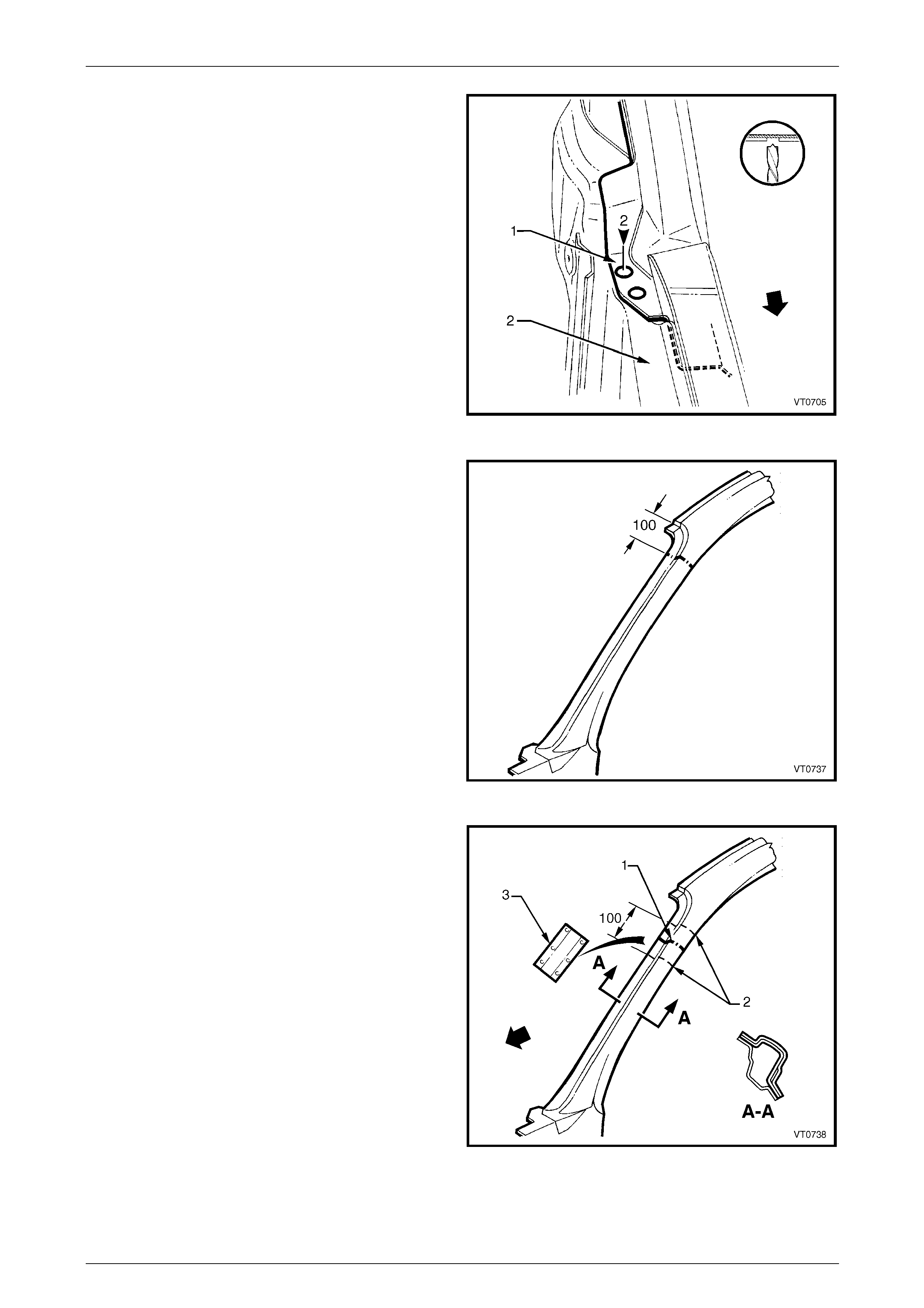
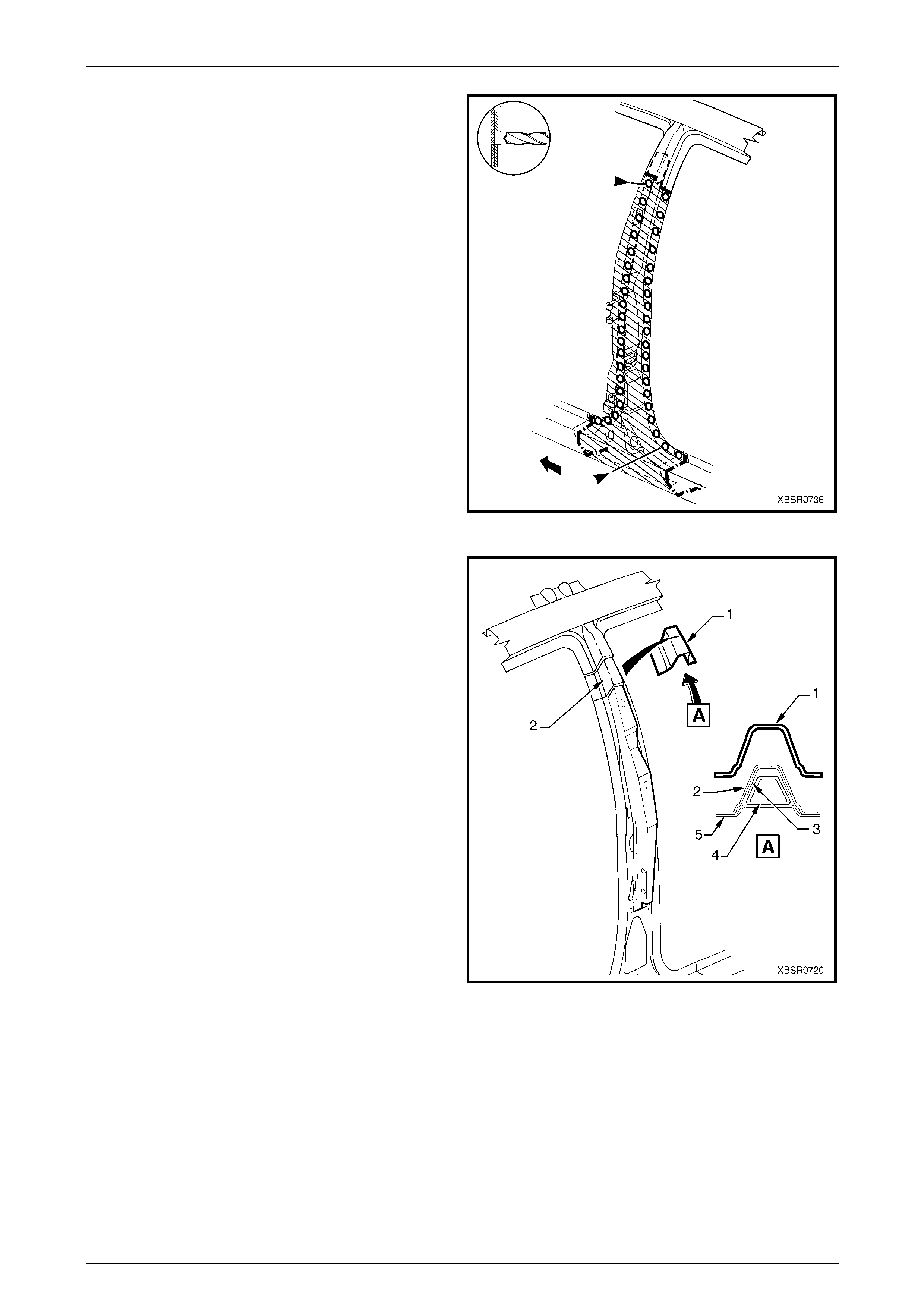
9 Select a cutting point on the hinge pillar. This cut point
should be within the region specified.
Figure 7B – 49
10 At the selected point (1), cut through the outer and
reinforcement panels, leaving the inner panel intact.
11 Mark the inner panel at points 50 mm either side of the
cut line on the outer panel and cut the inner panel at
these two points (2). Spot cut the welds and remove
the 100 mm section of inner panel (3).
Figure 7B – 50
7B Body Side – Wagon Page 7B-28
Page 7B-28
12 Spot cut the welds on the windshield side flange, up to
the point of the cut.
Figure 7B – 51
13 Cut through the rocker panel section of the door
opening frame assembly. The cut point (1) sh ould be
through the third rocker panel moulding attaching hole
(2). Cut through both the outer panel and the
reinforcement.
Figure 7B – 52
14 Spot cut the welds on the flange along the front door
opening, from the cut near the top of the hinge pill ar
(1) to the cut in the rocker panel (2).
15 Spot cut the welds along the flange (3) below the
rocker panel to the point of the cut.
16 Remove the partial hinge p illar from the vehicle, then
repair any damage to adjacent parts.
17 Check and rectify the alignme nt of
the body as requir ed,
refer to Section 3B Body Construction – Wagon.
Figure 7B – 53
7B Body Side – Wagon Page 7B-29
Page 7B-29
Replace
NOTE
• Spot welding is the preferred method for
attaching of panels and should be used
whenever possible. Where the spot welding
equipment available will not access the
required weld position, a plug weld should be
performed.
• The same number and position of spot welds
(or plug welds) should be used when
replacing the panel, as was used during
manufacture, in order to maintain the original
structural strength of the vehicle.
1 Cut a replacement panel section (1), accurately
measuring the position of cuts to match the section
removed.
Figure 7B – 54
2 Remove a section of inner rocker panel (1). Cut
50 mm each side of the cut in the rocker panel. T his
allows access for welding the rocker panel
reinforcement.
Figure 7B – 55
7B Body Side – Wagon Page 7B-30
Page 7B-30
3 Either manufacture a new section or cut an existing
length of surplus rocker panel section, to form a
reinforcement (1), approximately 100 mm in length.
4 Prepare all mating surfaces and treat with Weld
Through Primer (Item 1) as required,
refer to Section 3B Body Construction – Wagon.
5 Clamp this reinforcement firmly behind the cut section
of rocker panel on the vehicle and spot or plug weld in
place. Position welds at a maximum spacing of 35 mm
apart.
Figure 7B – 56
6 Using a similar technique, ma nufacture or cut a
section of reinforcement panel (1) appro ximat ely
60 mm long, to fit on the inside the outer panel of the
replacement hinge pillar (2) at the point of th e cut.
NOTE
Remove the flanges from this reinforcement
panel.
7 Prepare all mating surfaces and treat with Weld
Through Primer (Item 1) as required,
refer to Section 3B Body Construction – Wagon.
8 Clamp the reinforcement panel firmly behind the outer
panel of the cut section of the hinge pillar and spot
weld (3) in place.
9 Mark the new hinge pillar with drilling locations in
preparation for plug welding where required. Drill holes
as marked.
10 Prepare all mating surfaces and treat with Weld
Through Primer (Item 1) as required,
refer to Section 3B Body Construction – Wagon.
11 Apply Acrylic Spot Weld Sealer (Item 2),
refer to Section 3B Body Construction – Wagon.
Figure 7B – 57
12 Clamp the replacement panel (1) in position on the
vehicle and check the door opening dimensions.
Refer to Section 3B Body Construction – Wagon.
Adjust position as required.
Figure 7B – 58
7B Body Side – Wagon Page 7B-31
Page 7B-31
13 Plug weld (1) the top of the pillar to the manufactured
reinforcement, then MIG butt weld (2) the two sections
together.
Figure 7B – 59
14 Plug weld (1) the new panel in the rocker panel region,
then MIG butt weld (2) the two sections together.
Figure 7B – 60
15 Gaining access through the removed sectio n of inner
panel, MIG butt weld (1) the reinforcement panel
together.
16 Butt weld the removed access panel (2) in position.
Replace the spot welds with the same number that
was removed.
Figure 7B – 61
7B Body Side – Wagon Page 7B-32
Page 7B-32
17 Spot weld (1) the hinge pillar section along the door
opening flange.
18 Spot weld (2) the flange beneath the rocker pan el,
attaching the new panel to the inner rocker panel.
Figure 7B – 62
19 Spot weld (1) the pillar along the windshield opening
flange.
Figure 7B – 63
20 Spot or plug weld the door opening frame assembly
(1) to the hinge pillar inner panel assembly (2) at the
base of the hinge pillar.
Figure 7B – 64
7B Body Side – Wagon Page 7B-33
Page 7B-33
21 Spot or plug weld the door opening frame assembly to
the inner rocker panel and to the hinge pillar inner
panel assembly. If the sheetmetal was modified to
allow access to these welds, it should be repaired to
its original configuration.
Figure 7B – 65
22 Plug weld the inner rocker pa nel and hinge pillar inner
panel assembly to the rocker panel reinforcement.
Figure 7B – 66
23 Gaining access through the section of removed in ner
rocker panel, MIG butt weld (1) the new section of
rocker panel reinforcement to the existing section.
24 Replace the removed section of inner rocker panel (2)
by MIG butt welding it in place and spot welding it
along the door opening flange. Replace the spot welds
with the same number of as were cut out.
25 Dress the butt welds by grinding or sanding, ensuring
sufficient material remains to guarantee the strength of
the weld.
26 Install the door hinges,
refer to Section 8 Doors, Liftgate and Endgat e.
27 Refinish and paint panels and other components as
required. Refer to Section 3 Body Construction .
28 Apply Joint Sealer (Item 3) as required.
Refer to Section 3B Body Construction – Wagon.
Figure 7B – 67
29 Apply Cavity Wax (Item 8) as required to the inside of any box secti ons or areas inaccessible to paint,
refer to Section 3B Body Construction – Wagon.
30 Install the dash panel bolt through the hinge pillar and tighten to the specified torque.
Dash Panel Retaining Bolt
Torque Specification ...............................35.0 – 45.0 Nm
31 Replace the windshield, refer to Section 1A6 Stationary Windows in the MY2005 VZ Service Information.
32 Install the remaining components as described in the appr opriate Section of the MY2005 VZ Service Information.
7B Body Side – Wagon Page 7B-34
Page 7B-34
2.7 Door Opening Frame Assembly – Partial
Replace. Centre Pillar
NOTE
Cavity Foam is used within the hinge, centre and
lock pillar cavities. Care is required when
repairing the vehicle in these areas, refer to
Section 2 Precautions prior to beginning any work
for further information.
Remove
1 Remove the adjacent bolt-on panels a nd components
as described in the appropriate Section of the MY2005
VZ Service Information.
2 Install the vehicle on a suitab le fixture. As a minimum,
support the appropriate structural sections of the
vehicle on safety stands. Secure a suitable tool
between the front door openi ng flanges to maintain
alignment.
Figure 7B – 68
3 Cut through the door opening frame assembly (1) at
the join of the rocker panel reinforcement and centre
pillar reinforcement (2).
NOTE
Make the cut carefully as the rocker panel
reinforcement must not be cut. The centre pillar
reinforcement is removed with the centre pillar
section.
Figure 7B – 69
7B Body Side – Wagon Page 7B-35
Page 7B-35
4 Cut through the door opening frame assembly (1)
rearward of the dimple (2) in the flange.
NOTE
Make the cut carefully as the quarter panel inner
assembly must not be cut.
Figure 7B – 70
5 Spot cut the welds attaching the underbod y jacking
locator (1) and remove.
6 Spot cut the welds on the flange attaching the centre
pillar section to the inner rocker panel (6).
Refer to weld group A.
7 Spot cut the welds on the underside of the rocker
panel attaching the centre pillar section to the quarter
panel inner assembly (7). Refer to weld group B.
Figure 7B – 71
8 Cut the door opening frame a ssembly (1) and centre
pillar reinforcement (2) at the intersection point of the
centre pillar upper reinforcement (3). T he intersection
point can be seen by looking at the side of the flange.
NOTE
Do not cut through the centre pillar inner
reinforcement assembly (4) or quarter panel
inner assembly (5).
Figure 7B – 72
7B Body Side – Wagon Page 7B-36
Page 7B-36
9 Spot cut the welds on the door opening flanges on
both sides of the centre pillar and remove the centre
pillar section from the vehicle.
Figure 7B – 73
10 From the remaining section of centre pillar, carefully
remove enough of the outer skin (1) to expose the
spot welds joining the overlap pin g sections of centre
pillar upper reinforcement (2) and centre pillar
reinforcement (3).
NOTE
Do not cut the centre pillar inner reinforcement
assembly (4) and quarter panel inner assembly
(5).
Figure 7B – 74
7B Body Side – Wagon Page 7B-37
Page 7B-37
11 Spot cut as shown, to remove the remaining tongue
(1) of the centre pillar reinforcement. Leave the holes
drilled in reinforcement to facilitate plug welding the
replacement section.
Figure 7B – 75
Replace
NOTE
• Spot welding is the preferred method for
attaching of panels and should be used
whenever possible. Where the spot welding
equipment available will not access the
required weld position, a plug weld should be
performed.
• The same number and position of spot welds
(or plug welds) should be used when
replacing the panel, as was used during
manufacture, in order to maintain the original
structural strength of the vehicle.
1 Cut the replacement panel through rocker section as
shown. Accurately measure the positio n of cuts to
match the removed panel section.
Figure 7B – 76
2 Cut the replacement panel at the top of the centre
pillar (1).
NOTE
Position the cut above the tongue on the centre
pillar reinforcement, which is visible from the
back of the panel.
3 Adjust the cut on the vehicle side of the outer panel so
that it matches the cut on the replacement section.
Figure 7B – 77
7B Body Side – Wagon Page 7B-38
Page 7B-38
4 On the replacement panel, cut along each side and
bend back the outer panel (3). This will expose the
spot welds attaching the remaining piece of upper
reinforcement (1) to the tongue (2) of the centre pillar
reinforcement.
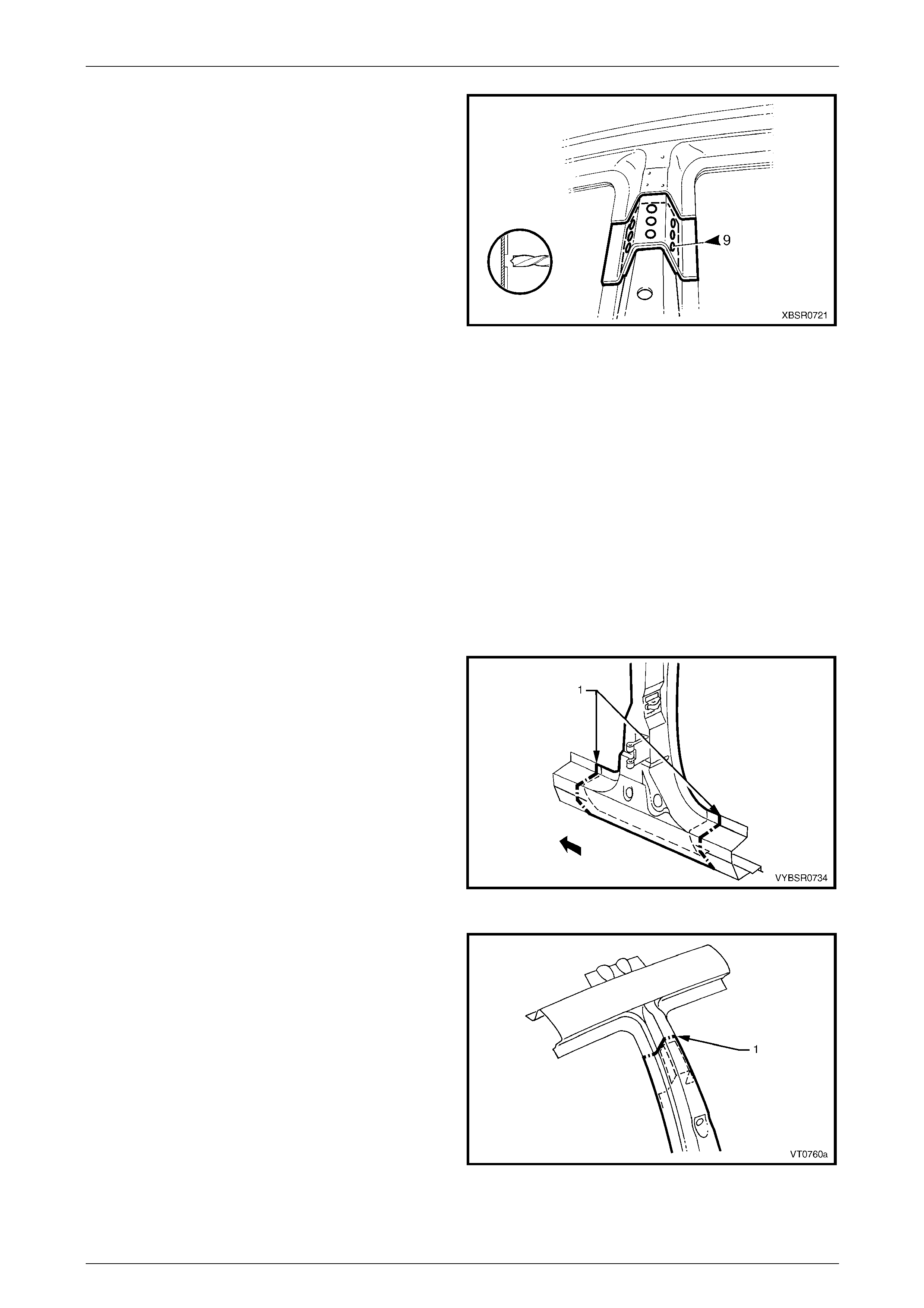
Figure 7B – 78
5 Spot cut the nine welds and remove the remaining
section of centre pillar upper reinforc ement (1) from
the replacement panel.
Figure 7B – 79
6 Cut two sections from surplus rocker panel pieces, or
manufacture new sections (1), each ap proximately
100 mm in length.
7 Prepare the mating surfaces and treat with Weld
Through Primer (Item 1) as required,
refer to Section 3B Body Construction – Wagon.
8 Clamp these sections firmly behi nd both the cut faces
of rocker panel on the vehicle and spot or plug weld in
place. Perform the welds at a maximum spacing of
35 mm.
9 Mark the new panel with drilling locations in
preparation for plug welding where required. Drill holes
as marked.
10 Prepare all mating surfaces and treat with Weld
Through Primer (Item 1) as required,
refer to Section 3B Body Construction – Wagon.
Figure 7B – 80
7B Body Side – Wagon Page 7B-39
Page 7B-39
11 Install the replacement panel i n position, sliding the
tongue of the centre pillar reinforcement (1) behind the
centre pillar upper reinforcement (2).
NOTE
Manipulate the rocker panel section in position,
inserting the front first, then the rear.
12 Clamp the assembly in place and p lug weld the centre
pillar upper reinforcement to the centre pill ar
reinforcement at the upper join.
13 Plug weld the rocker panel section to the
reinforcement sections.
14 Spot weld along the door openin g flanges on both
sides of the centre pillar.
Figure 7B – 81
15 Fold the outer panel back in position at the top of the
centre pillar. Spot weld along the door flange section
and MIG butt weld the sections together as shown.
16 MIG butt weld the joins in the rocker panel.
Figure 7B – 82
7B Body Side – Wagon Page 7B-40
Page 7B-40
17 Plug weld the flange attaching the centre pil lar section
(1) to the inner rocker panel (2).
Refer to weld group A.
18 Plug weld on the underside of the rocker panel the
centre pillar section to the quarter panel inner
assembly (3). Refer to weld group B.
19 Plug weld the underbody jacking locator (4) in place.
20 Install the door hinges,
refer to Section 8 Doors, Liftgate and Endgat e.
21 Dress the welds by grinding or sanding, ensuring
sufficient material remains to guarantee the strength of
the weld. Finish the area using an appropriate
technique.
22 Refinish and paint panels and other components as
required. Refer to Section 3 Body Construction .
23 Apply Joint Sealer (Item 3) as required.
Refer to Section 3B Body Construction – Wagon.
24 Apply Cavity Wax (Item 8) as required to the inside of
any box sections or areas inaccessible to paint,
refer to Section 3B Body Construction – Wagon.
25 Insert Cavity Foam into the centre pillar as r equired,
refer to Section 2 Precautions.
26 Install the remaining components as described in the
appropriate Section of the MY2005 VZ Service
Information.
Figure 7B – 83
7B Body Side – Wagon Page 7B-41
Page 7B-41
2.8 Door Opening Frame Assembly – Partial
Replace, Lock Pillar
Remove
1 Remove the adjacent bolt-on panels a nd components
as described in the appropriate Section of the MY2005
VZ Service Information.
2 Install the vehicle on a suitab le fixture. As a minimum,
support the appropriate structural sections of the
vehicle on safety stands.
3 Remove the rear window assembly, refer to
Section 1A6 Stationary Windows in the MY2005 VZ
Service Information.
4 Remove rear quarter panel,
refer to 2.1 Rear Quarter Panel – Replace.
Figure 7B – 84
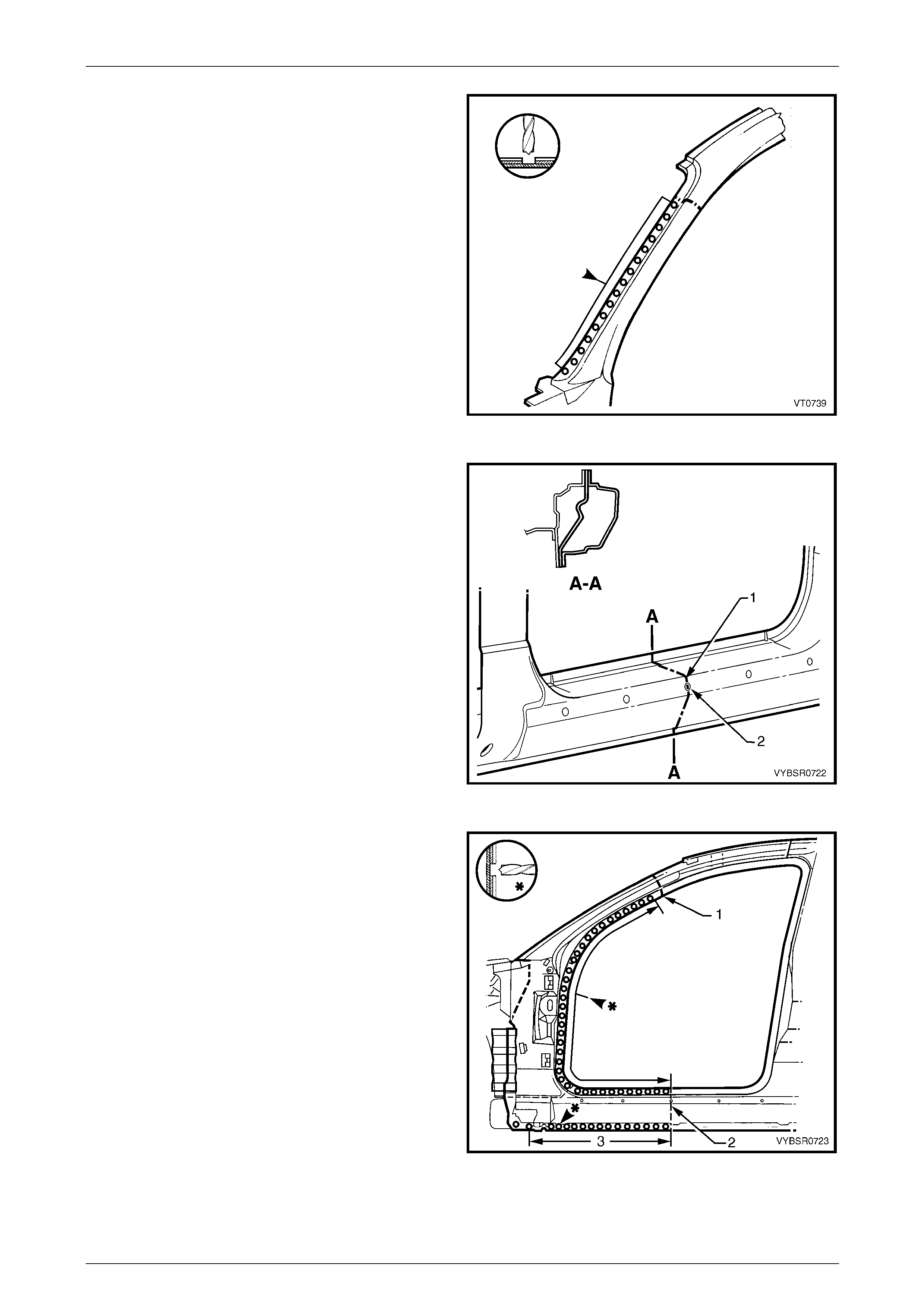
5 Select a cut line (1) on the upper region of the lock
pillar within the region specified.
6 Carefully cut through the outer panel, leaving the
quarter panel inner assembly (2) intact.
NOTE
There is no reinforcement panel in this area of
the vehicle.
Figure 7B – 85
7 Select a cutting position on the rocker panel section of
the door opening frame assembly, rear of the dimple in
the flange (1). If possible, make the cut in the area that
will be covered by the rear quarter panel. Cut through
the outer panel (2), leaving the quarter pan el inner
assembly (3) intact.
Figure 7B – 86
7B Body Side – Wagon Page 7B-42
Page 7B-42
8 Spot cut the welds on the flange around the rear door
opening attaching the section of the door opening
frame assembly to the quarter panel in ner assembly.
Begin from the cut through the top of the pilla r (1) and
continue to the cut through the rocker panel section (2)
as required.
NOTE
Some of the welds shown may have been
removed with the rear quarter panel.
9 Spot cut the welds down the flange of the rear side
glass opening (3), beginning a t the point of the cut
through the lock pillar.
Figure 7B – 87
10 Spot cut the welds on the flange below the rocker
panel as required, attaching the do or opening frame
assembly to the inner rocker panel.
NOTE
Spots rear of those shown may have been
removed with the rear quarter panel, if not
remove any remaining.
Figure 7B – 88
11 Spot cut the welds below the rocker panel as required,
attaching the door opening fram e assembly to the
quarter panel inner assembly.
NOTE
Spots rear of those shown may have been
removed with the rear quarter panel, if not
remove any remaining.
Figure 7B – 89
7B Body Side – Wagon Page 7B-43
Page 7B-43
12 Spot cut any welds remaining around the wheel house
as required (most would have been removed with the
rear quarter panel), attaching the door o pe ning frame
assembly (1) to the quarter panel inner assembly (2).
13 Remove the replacement sect ion from the vehicle,
then repair any damage to adjacent parts as required.
14 Check and rectify the alignme nt of
the body as requir ed,
refer to Section 3B Body Construction – Wagon.
Figure 7B – 90
Replace
NOTE
• Spot welding is the preferred method for
attaching of panels and should be used
whenever possible. Where the spot welding
equipment available will not access the
required weld position, a plug weld should be
performed.
• The same number and position of spot welds
(or plug welds) should be used when
replacing the panel, as was used during
manufacture, in order to maintain the original
structural strength of the vehicle.
1 Cut a replacement section from a new door opening frame assembly, accurately measuring the position of cuts to
match the removed section.
2 Manufacture a reinforcement ( 1), appro x. 100 mm in
length to match the inside of the lock pillar section at
the cut.
3 Prepare the mating surfaces and treat with Weld
Through Primer (Item 1) as required,
refer to Section 3B Body Construction – Wagon.
4 Clamp the reinforcement firmly behind the cut face of
the lock pillar section of the door openi ng frame
assembly on the vehicle and spot or plug weld in
place.
Figure 7B – 91
7B Body Side – Wagon Page 7B-44
Page 7B-44
5 Using the same technique, manufactur e or cut a
section of reinforcement panel (1), approx. 100 mm
long, to fit the inside of the existing rocker panel at the
point of the cut.
6 Prepare the mating surfaces and treat with Weld
Through Primer (Item 1) as required,
refer to Section 3B Body Construction – Wagon.
7 Clamp the manufactured reinforcement panel firmly to
the inside of the rocker panel on the ve hicle and plug
weld in position. Position welds at a maximum spacing
of 35 mm.
8 Mark the new lock pillar panel with drilling locations in
preparation for plug welding. Drill holes as required.
9 Prepare all mating surfaces and treat with Weld
Through Primer (Item 1) as required,
refer to Section 3B Body Construction – Wagon.
Figure 7B – 92
10 Clamp the new lock pillar section in place on the
vehicle and check the door opening dimensions,
refer to Section 3B Body Construction – Wagon.
11 Plug weld the replacement panel to the ma nufactured
reinforcement sections in the rocker panel area and at
the top of the pillar.
12 MIG butt weld the joins in both these areas.
Figure 7B – 93
13 Spot weld several places alon g the flange around the
rear door opening (1) to retain new section in position.
NOTE
Fully spot weld this flan ge when the r ear quarter
panel is installed, welding through all three
panels, refer to 2.1 Rear Quarter Panel –
Replace.
14 The flange of the rear side glass ope ning (2) may be
spot welded in one or t wo places to hold i n position.
NOTE
Final weld this flange when the rear quarter
panel is installed, refer to 2.1 Rear Quarter
Panel – Replace.
Figure 7B – 94
7B Body Side – Wagon Page 7B-45
Page 7B-45
15 Spot weld the flange below the rocker panel as
required, attaching the replac ement section to the
inner rocker panel.
NOTE
Where the rear quarter panel locates, place two
welds to secure the replacement section. Final
weld this flange when the rear quarter panel is
installed, refer to 2.1 Rear Quarter Panel –
Replace.
Figure 7B – 95
16 Plug weld below the rocker panel as required,
attaching the replacement section to the quarter panel
inner assembly.
NOTE
Where the rear quarter panel locates, place two
welds to secure the replacement section. Final
weld this flange when the rear quarter panel is
installed, refer to 2.1 Rear Quarter Panel –
Replace.
Figure 7B – 96
17 Spot weld several places around the wheelhouse to
retain new section in position.
NOTE
Fully spot weld this flan ge when the r ear quarter
panel is installed, refer to 2.1 Rear Quarter
Panel – Replace.
18 Clean up the welds made where the rear quarter panel
is located and prime all bare metal.
19 Replace rear quarter panel,
refer to 2.1 Rear Quarter Panel – Replace.
20 Refinish and paint panels and other components as
required. Refer to Section 3 Body Construction .
21 Apply Joint Sealer (Item 3) as required.
Refer to Section 3B Body Construction – Wagon.
22 Apply Cavity Wax (Item 8) as required to the inside of
any box sections or areas inaccessible to paint,
refer to Section 3B Body Construction – Wagon.
23 Install the quarter window assembly, refer to
Section 1A6 Stationary Windows in the MY2005 VZ
Service Information.
24 Install the remaining components as described in the
appropriate Section of the MY2005 VZ Service
Information.
Figure 7B – 97
7B Body Side – Wagon Page 7B-46
Page 7B-46
2.9 Door Opening Frame Assembly – Partial
Replace, Rocker Panel
This procedure details the replacement of the
rocker panel section of the door opening
frame assembly.
As there are several critical reinforcements in
the lower hinge pillar area, the rocker panel
section must not be cut forward of the area
shown. If the rocker panel is damaged
forward of this area, replace the rocker panel
and partial hinge pillar as one section. Modify
this procedure accordingly, also referring to
2.6 Door Opening Frame Assembly – Partial
Replace, Hinge Pillar.
Remove
1 Remove the adjacent bolt-on panels a nd components
as described in the appropriate Section of the MY2005
VZ Service Information.
2 Remove the rear quarter panel,
refer to 2.1 Rear Quarter Panel – Replace.
3 Secure the vehicle on a suitable fixture. As a
minimum, support the appropriate structural s ections
of the vehicle on safety stands. Install suitable bracing
in the vehicle to ensure the correct body alignment is
maintained when the rocker pane l section is removed.
Figure 7B – 98
4 Cut through the rocker panel section of the door
opening frame assembly. The cut point (1) must not be
further forward than the third rocker panel m oulding
attaching hole (2). Cut through both the outer panel
and the reinforcement.
Figure 7B – 99
7B Body Side – Wagon Page 7B-47
Page 7B-47
5 Using a suitable cutting tool, cut through the centre
pillar at a position 30 mm below the lower edge of the
door hinge. Cut through both the door opening frame
assembly (1) and centre pillar reinforcement (2).
Figure 7B – 100
6 Select a cutting point through the rocker pan el,
rearward of the dimple (1) in the flange. Cut through
the door opening frame assembly (2) only.
NOTE
The cutting point can be anywhere rearward of
point 1, however if it is rear of point 3 the rear
quarter panel will require removal,
refer to 2.1 Rear Quarter Panel – Replace
Figure 7B – 101
7 Depending on the cut location, spot cut any welds
remaining around the wheelhouse as required (most
would have been removed with the rear quarter
panel), attaching the door opening frame assembly (1)
to the quarter panel inner assembly (2).
8 Spot cut along the vertical flange below the rocker
panel to separate the door opening frame assembly
from the inner rocker panel and the rear flo or pan el
outer extension. Refer to Figure 7B – 103.
NOTE
Depending on the cut line position, many of
these welds may have been previously removed
if the rear quarter panel has been remove d.
Figure 7B – 102
7B Body Side – Wagon Page 7B-48
Page 7B-48
Figure 7B – 103
9 Spot cut the welds attaching the rocker panel section to the quarter p an el inner assembly as required.
Refer to Figure 7B – 104.
NOTE
Depending on t he cut line position, ma ny of these
welds may have been previously removed if the
rear quarter panel has been remove d.
Figure 7B – 104
7B Body Side – Wagon Page 7B-49
Page 7B-49
10 Spot cut the welds along the lower edge of the front
and rear door openings as required, to complete the
detachment of the rocker panel section.
11 Remove the panel from the vehicle, then repair any
damage to adjacent parts.
12 Check and rectify the alignme nt of
the body as requir ed,
refer to Section 3B Body Construction – Wagon.
Figure 7B – 105
Replace
NOTE
• Spot welding is the preferred method for
attaching of panels and should be used
whenever possible. Where the spot welding
equipment available will not access the
required weld position, a plug weld should be
performed.
• The same number and position of spot welds
(or plug welds) should be used when
replacing the panel, as was used during
manufacture, in order to maintain the original
structural strength of the vehicle.
1 Cut a new replacement rocker panel section. Accuratel y measure the p ositi on of the cuts on the removed section.
2 Remove a section of inner rocker panel (1), cut 50 mm
each side of the cut in the rocker panel. This allows
access for welding the rocker panel reinf orcement.
Figure 7B – 106
7B Body Side – Wagon Page 7B-50
Page 7B-50
3 Manufacture or cut a reinforcement (1) (appr oximately
100 mm long) to fit on the inside of the existing rocker
panel at the point of the cut.
4 Prepare the mating surfaces and treat with Weld
Through Primer (Item 1) as required,
refer to Section 3B Body Construction – Wagon.
5 Clamp the manufactured reinforcement firmly to the
inside of the rocker panel section of the d oor opening
frame assembly on the vehicle and plug weld in
position. Position welds at a maximum sp acing of
35 mm.
Figure 7B – 107
6 Manufacture or cut a reinforcement (1) (appr oximately
100 mm long) to fit inside of the existing centre pillar
section at the point of the cut.
7 Prepare the mating surfaces and treat with Weld
Through Primer (Item 1) as required,
refer to Section 3B Body Construction – Wagon.
8 Clamp the manufactured reinforcement panel firmly to
the inside of the outer panel of the door opening frame
assembly on the vehicle and p lug weld in position.
Position welds at a maximum spacing of 35 mm.
9 Repeat steps 6, 7 and 8 and install a reinforcement at
the rear rocker panel / lock pillar lower cut as required.
10 Mark the replacement rocker panel section with drilling
positions in preparation for plug welding as required.
Figure 7B – 108
NOTE
The outer panel will be plug welded from the
outer side of the vehicle, while the rocker panel
and centre pillar reinforcements will be butt
welded from the inner side of the vehicle.
11 Prepare all mating surfaces and treat with Weld Through Primer (Item 1) as required,
refer to Section 3B Body Construction – Wagon.
12 Install the replacement section onto the vehicle by sliding the front and centre pillar sections onto the
reinforcements, while lifting the rear into posi tion.
13 Clamp the panel in position.
7B Body Side – Wagon Page 7B-51
Page 7B-51
14 Weld the new section to the centre pillar by plug
welding (1).
15 MIG butt weld the centre pillar reinforcement from
inside the centre pillar, through the large ho le in the
inner panel immediately behind the weld.
16 Finish the centre pillar attachment by MIG welding (2)
along the join of the outer panel.
Figure 7B – 109
17 Plug weld (1) the replacement section at the front join,
then MIG butt weld (2) the two sections together.
Figure 7B – 110
18 Gaining access through the section of removed floor
side panel, MIG butt weld (1) the new section of rocker
panel reinforcement to the existing section.
19 Replace the removed section of floor side panel (2) by
MIG butt welding it in place and spot welding it along
the door opening flange. Repl ace the spot welds with
the same number as were removed.
Figure 7B – 111
7B Body Side – Wagon Page 7B-52
Page 7B-52
20 Plug weld the rear join as required.
21 MIG butt weld the joint line between the panels.
Figure 7B – 112
22 Spot or plug weld the flanges of the front and rear door
openings as required.
NOTE
Use the same number and position of welds as
removed during removal.
23 Spot or plug weld the door opening frame al ong the
flange below the rocker panel as required,
refer to Figure 7B – 114.
NOTE
If the rear quarter panel was removed, plac e two
welds where the rear quarter panel will overlap
the flange to hold the replacement section in
position. Fully spot weld this flange when the
rear quarter panel is being attached, welding
through all panels, refer to 2.1 Rear Quarter
Panel – Replace.
Figure 7B – 113
Figure 7B – 114
7B Body Side – Wagon Page 7B-53
Page 7B-53
24 Plug weld up through the rocker panel to attach the replacement section to the quarter panel inner assembly.
Refer to Figure 7B – 115.
NOTE
If the rear quarter panel was removed, place two
welds where the rear quarter panel will overlap
the panel to hold the replacement section in
position. Fully spot weld this area when the rear
quarter panel is being attached, welding through
all panels. Refer to 2.1 Rear Quarter Panel –
Replace.
Figure 7B – 115
25 If required, spot weld the replacement section to the
quarter panel inner assembly around the rear wheel
arch at several places to retain new section in position
NOTE
Fully spot weld this flan ge when the r ear quarter
panel is installed, welding through all three
panels. Refer to 2.1 Rear Quarter Panel –
Replace.
26 Clean up the welds made where the rear quarter panel
is located and prime all bare metal.
27 Install the rear quarter panel,
refer to 2.1 Rear Quarter Panel – Replace.
28 Refinish and paint panels and other components as
required. Refer to Section 3 Body Construction .
29 Apply Joint Sealer (Item 3) as required.
Refer to Section 3B Body Construction – Wagon.
30 Apply Cavity Wax (Item 8) as required to the inside of
any box sections or areas inaccessible to paint,
refer to Section 3B Body Construction – Wagon.
31 Install the remaining components as described in the
appropriate Section of the MY2005 VZ Service
Information.
Figure 7B – 116
7B Body Side – Wagon Page 7B-54
Page 7B-54
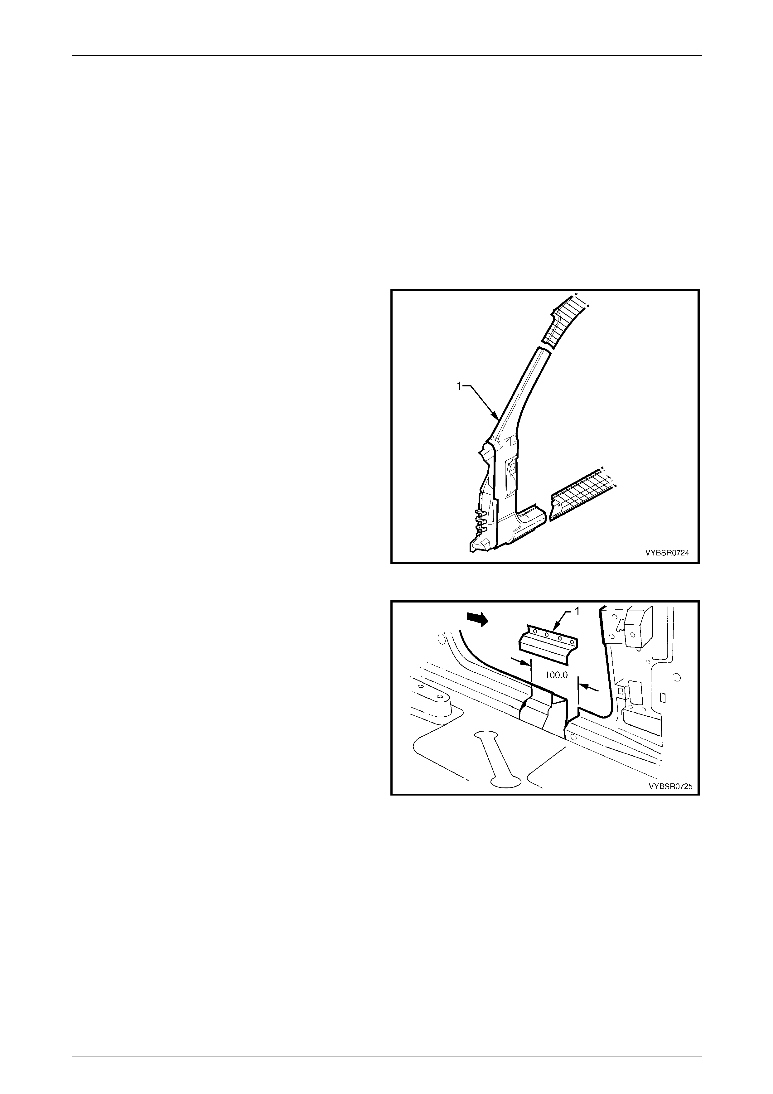
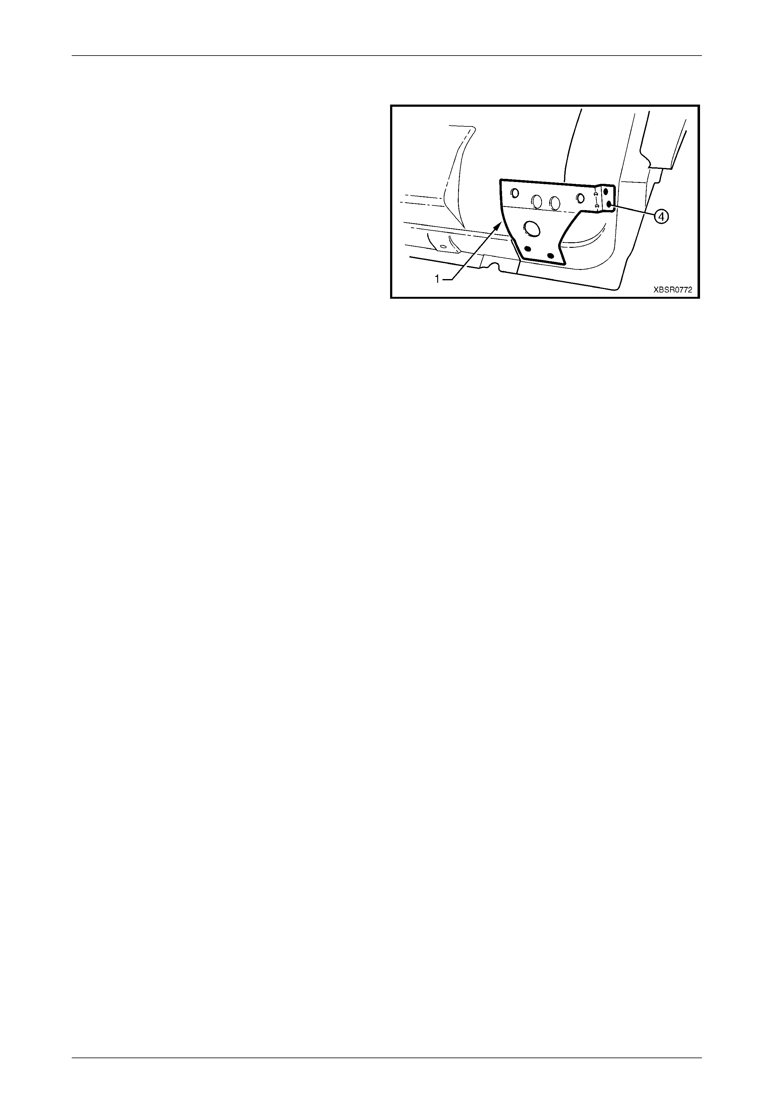
2.10 Fender Lower Rear Bracket – Replace
The fender lower rear bracket (1) is spot welded at four
places to the door opening fra m e assembly.
Clamp the fender lower rear bracket positi on as shown prior
to plug welding and check the alig nment of the fender to the
body and front door.
Refinish and paint panels and other components as
required. Refer to Section 3 Body Construction .
Apply Cavity Wax (Item 8) as r equired to the inside of any
box sections or areas inaccessible to paint,
refer to Section 3B Body Construction – Wagon.
Figure 7B – 117
7B Body Side – Wagon Page 7B-55
Page 7B-55
2.11 Hinge Pillar Inner Panel Assembly –
Replace
Remove
1 Remove the adjacent bolt-on panels a nd components
as described in the appropriate Section of the MY2005
VZ Service Information.
2 Remove the door opening frame assembly, refer to
2.5 Door Opening Frame Assembly – Repl ace, or
remove the hinge pillar section of the door opening
frame assembly, refer to 2.6 Door Opening Frame
Assembly – Partial Replace, Hinge Pil lar .
3 If required, remove the dash panel assembl y,
refer to Section 5 Cockpit Module in this Supplement.
NOTE
If the cockpit module is not damaged an
alternative is provided in this p rocedure.
4 Add bracing as requir ed to maintain the alignment of
the vehicle structure.
Figure 7B – 118
5 Grind the MIG welds (1) attaching the hinge pill ar inner
panel assembly to the inner rocker panel.
Figure 7B – 119
6 Spot cut the welds attaching the hinge pillar i nner
panel assembly to the roof front header and quarter
panel inner extension.
NOTE
Structural adhesive is applied to join (1). If the
roof panel has not been removed, it will be very
difficult to remove the panel. As an alternative:
• If only the lower section is damaged, detach
the hinge pillar inner upper panel (1) from the
hinge pillar inner lo wer panel (2) and replac e
the lower panel, or
• Cut the hinge pillar inner panel assembly (3)
approximately 50 mm from the top of the
windscreen aperture. If a partial replacement
of the door opening frame assembly is being
performed, this point is 50 mm above the cut
in the outer panels (4).
Refer to Figure 7B – 121.
Figure 7B – 120
7B Body Side – Wagon Page 7B-56
Page 7B-56
Figure 7B – 121
7 Spot cut the welds attaching the hinge pillar i nner
panel assembly to the front wheelhouse panel and
front floor panel extension, refer to weld group A.
8 If the dash panel assembly was not removed, spot cut
the eight welds attaching the adhesive channels to the
hinge pillar inner panel assembly,
refer to weld group B.
9 If required, remove any remainin g spot welds where
the wheelhouse panel upper side rail attached the
front wheelhouse panel a nd hinge pillar inner panel
assembly.
10 Cut the adhesive between the dash panel assembl y
and hinge pillar inner panel assembly.
11 Remove the hinge pillar in ner panel assembly from the
vehicle and as required, cle an off any remaining
adhesive and ensure the adhesive channels are
removed.
12 Repair any damage to adjacent parts as required. Figure 7B – 122
Replace
NOTE
• Spot welding is the preferred method for
attaching of panels and should be used
whenever possible. Where the spot welding
equipment available will not access the
required weld position, a plug weld should be
performed.
• The same number and position of spot welds
(or plug welds) should be used when
replacing the panel, as was used during
manufacture, in order to maintain the original
structural strength of the vehicle.
1 If an alternate removal method was used, referring to Figure 7B – 121, either:
• Cut the replacement section to match the cut at the top of the hinge pill ar, or
• Spot cut the welds attaching the hinge pillar i nner upper panel to the hinge pillar inner lower panel.
2 Mark the new panel and drill holes in preparation for plug welding where required.
7B Body Side – Wagon Page 7B-57
Page 7B-57
3 Prepare all mating surfaces and treat with Weld Through Primer (Item 1) as required,
refer to Section 3B Body Construction – Wagon.
4 If the dash panel assembly was removed, it will be installed later, proceed to Step 7.
5 If the dash panel assembly was not removed, prepare the adh esive channels on the replacement section and the
dash panel assembly, refer to Section 5 Cockpit Modu le .
6 Mix the dash panel silic one adhesive refer to Section 5 Cockpit Module . Apply the a dh esive to fill the adhesive
channels on the replaceme nt section.
NOTE
Only the correct material described in
Section 5 Cockpit Module is to be used.
7 If the full hinge pillar inner panel assembly is being replac ed, apply structural adhesive (Item 6) to
the mating surfaces of the hinge pillar inner panel assembly and quarter panel inner extension,
refer to Section 3B Body Construction – Wagon.
8 Install and clamp the new panel in position on the
vehicle.
NOTE
If the dash panel assembly was not removed,
place the hinge pillar inner panel assembly (1)
slightly lower and slide it upwards ensuring the
dash panel flange (2) seats into the adhesive
channel.
9 Temporarily install the dash p anel attaching bolts
through the hinge pillar i nn er panel assembly and
within the plenum chamber.
10 Finish the application of the dash panel adhesive,
refer to Section 5 Cockpit Module .
Figure 7B – 123
11 If the full hinge pillar inner panel assembly was
removed, spot or plug weld the hinge pillar inner panel
assembly to the roof front header and quarter pane l
inner extension.
NOTE
Ensure the structural adhesive (Item 6), is
applied to the join (1) refer to Section 3B Body
Construction – Wagon
12 If only the lower section was removed, spot or plug
weld the hinge pillar inner upper panel (1) to the hinge
pillar inner lower panel (2), refer to Figure 7B – 125.
13 If the pillar was cut near the top of the windscreen
aperture, either MIG butt weld the join (3) if the full
door opening frame assembly was remov ed, or make
two tack welds to secure it until the door opening
frame assembly hinge pillar s ection is installed, also
refer to Figure 7B – 125.
Figure 7B – 124
7B Body Side – Wagon Page 7B-58
Page 7B-58
NOTE
This join forms the top access cut point for joining
of the reinforcement as described in
2.6 Door Opening Frame Assembly – Partial
Replace, Hinge Pillar .
Figure 7B – 125
14 Spot or plug weld the hinge pillar in ner panel assembly
to the front wheelhouse panel and front floor
extension.
Figure 7B – 126
15 MIG weld two places (1) across the inner rocker panel
and hinge pillar inner panel assembly.
16 Replace the door opening fra me assembly, refer to
2.5 Door Opening Frame Assembly – Repl ace or the
hinge pillar section of the door opening frame
assembly, refer to 2.6 Door Opening Frame Assembly
– Partial Replace, Hinge Pill ar.
17 Refinish and paint panels and other components as
required. Refer to Section 3 Body Construction .
18 Apply Joint Sealer (Item 3) as required.
Refer to Section 3B Body Construction – Wagon.
19 Apply Cavity Wax (Item 8) as required to the inside of
any box sections or areas inaccessible to paint,
refer to Section 3B Body Construction – Wagon.
20 Install the remaining components as described in the
appropriate Section of the MY2005 VZ Service
Information.
Figure 7B – 127
7B Body Side – Wagon Page 7B-59
Page 7B-59
2.12 Quarter Panel Inner Assembly – Replace
Remove
1 Remove the adjacent bolt-on panels a nd components
as described in the appropriate Section of the MY2005
VZ Service Information.
2 Mount the vehicle on a suitable jig to mai ntai n correct
body alignment when the quarter panel inner
assembly is removed.
3 Remove rear quarter panel and quarter panel
extension, refer to 2.1 Rear Quarter Panel – Replace
and 2.2 Quarter Panel Exten s ion – Replace.
4 Remove the roof panel, and partially remove the roof
bow panel and roof rear panel, refer to Section 9 Roof.
5 Remove the door opening frame assembly, refer to
2.5 Door Opening Frame Assembly – Repl ace.
6 Add further bracing tools as required, to maintain the
alignment of the vehicle structure.
Figure 7B – 128
7 Cut any remaining spot welds and grind the MIG welds
(1), attaching the quarter panel in ner assembly to the
inner rocker panel.
8 Spot cut the welds attaching the rear wheelhouse
inner to the rear floor panel assembly,
refer to Figure 7B – 130.
Figure 7B – 129
Figure 7B – 130
7B Body Side – Wagon Page 7B-60
Page 7B-60
9 Spot cut the welds attaching the quarter panel inner assem bly to the rear compartment floor assembly.
Refer to Figure 7B – 131.
NOTE
Some of the welds rear of the rear wheelhouse
inner, also attach the quarter outer lower rear
panel which will be removed with the quarter
panel inner assembly but is replaced separately.
Figure 7B – 131
10 The quarter panel inner extension (1) is attached
to the hinge pillar inner panel assembly with
spot welds and structural adhesive (2) (Item 6,
refer to Section 3B Body Construction – Wagon). As
the adhesive is extremely strong, cut through the
quarter panel inner extension just behind the join and
remove the remaining joint piece with a grinder.
NOTE
As an alternative, remove the spot welds from
the join (3), leaving the quarter panel inner
extension intac t.
11 Remove the quarter panel inner assembly from the
vehicle, then repair any damage to adjacent parts as
required.
12 Check and rectify the alignme nt of
the body as requir ed,
refer to Section 3B Body Construction – Wagon.
Figure 7B – 132
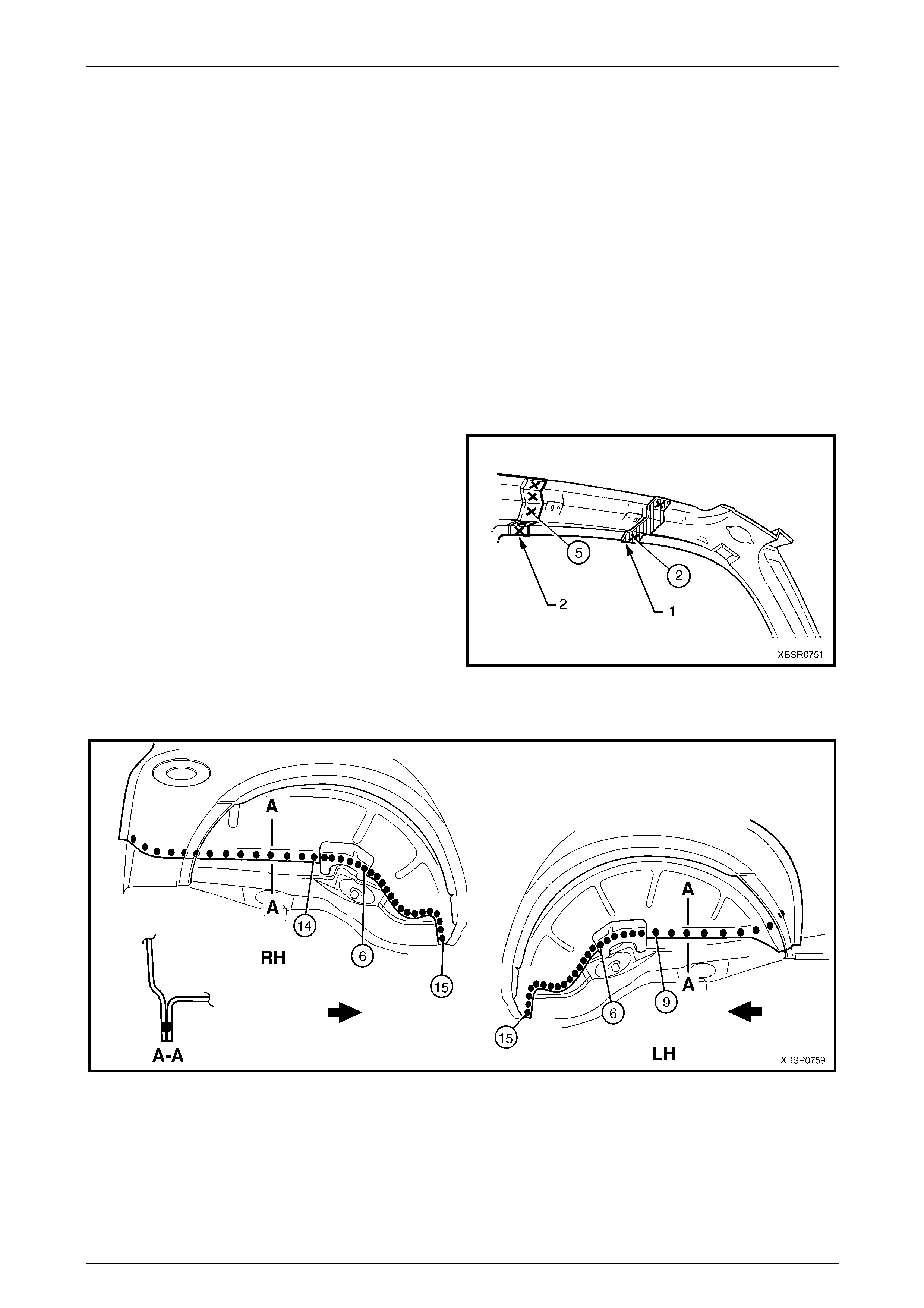
7B Body Side – Wagon Page 7B-61
Page 7B-61
Replace
NOTE
• Spot welding is the preferred method for
attaching of panels and should be used
whenever possible. Where the spot welding
equipment available will not access the
required weld position, a plug weld should be
performed.
• The same number and position of spot welds
(or plug welds) should be used when
replacing the panel, as was used during
manufacture, in order to maintain the original
structural strength of the vehicle.
1 Mark the new panel and drill holes in preparation for plug welding where required.
2 Prepare all mating surfaces and treat with Weld Through Primer (Item 1) as required,
refer to Section 3B Body Construction – Wagon.
3 Either, apply structural adhesive (Item 6, refer to
Section 3B Body Construction – Wagon) to the mating
surfaces of the quarter panel inner extensi on and
hinge pillar inner panel ass embly (1), if this joint was
cut or, remove the quarter panel inner extension from
the replacement section.
4 Clamp the new panel in position on the vehicle.
5 Depending on removal method either:
• Spot weld the quarter panel inner extension and
hinge pillar inner panel assembly join (1), or
• Spot weld the quarter panel inner ass embl y to
the quarter panel inner extension (2). Figure 7B – 133
6 Spot or plug weld the rear wheelhouse inner to the rear compartment floor assembly, refer Figure 7B – 134.
Figure 7B – 134
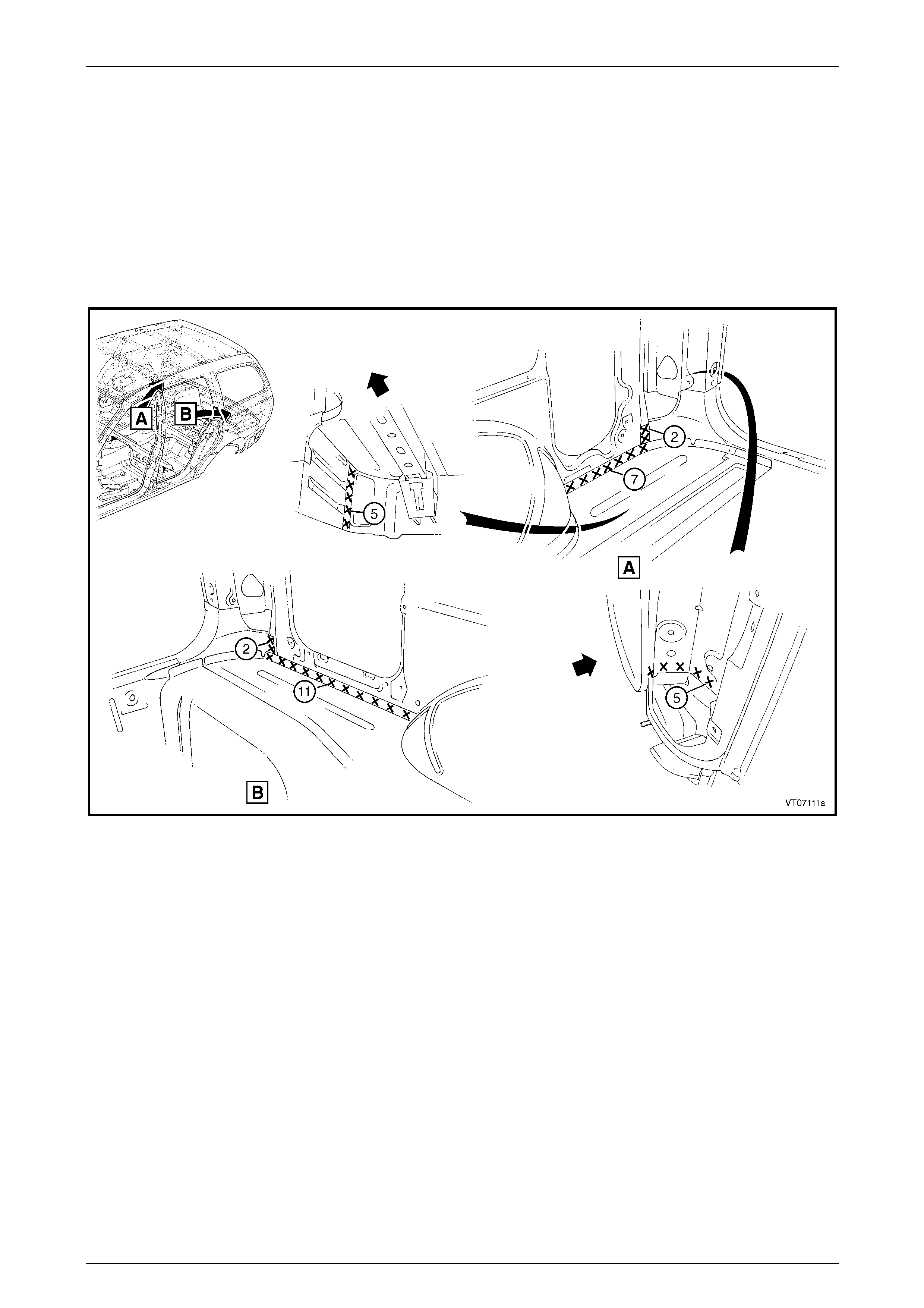
7B Body Side – Wagon Page 7B-62
Page 7B-62
7 Spot or plug weld the quarter panel in ner assembly to the rear compartment floor assembly,
refer to Figure 7B – 135.
NOTE
The welds along the rear compartment floor
assembly rear of the wheelhouse also attach the
quarter outer lower rear panel, which can be
replaced now, also refer to 2.4 Quarter Outer
Lower Rear Panel – Replace.
8 Weld the quarter panel inner lower extension to the rear end panel extension.
Figure 7B – 135
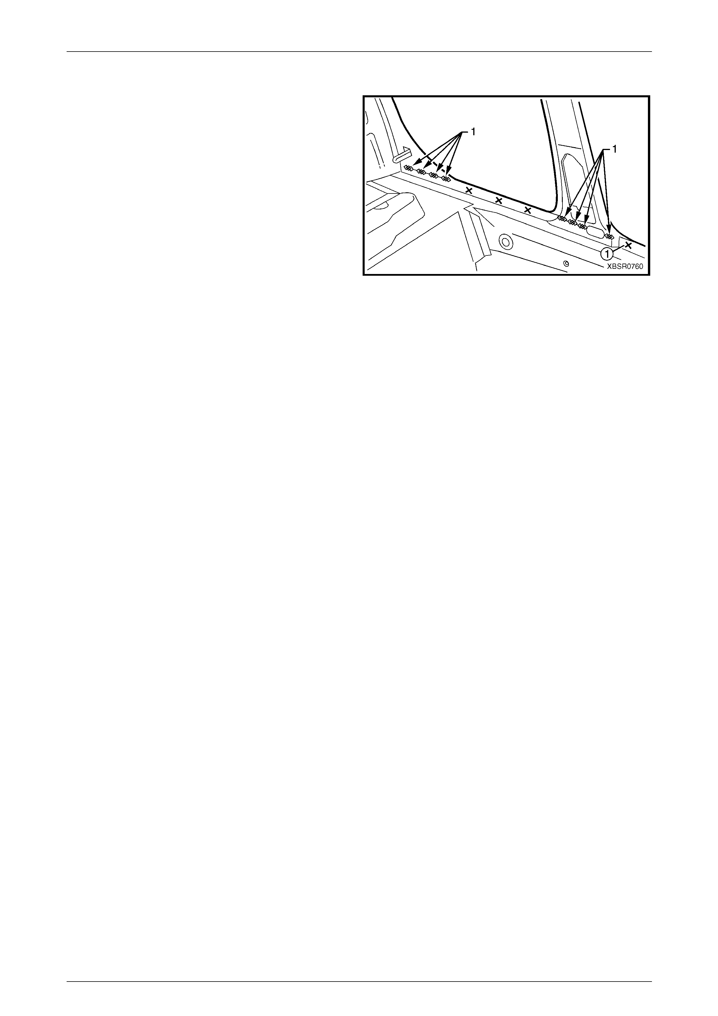
7B Body Side – Wagon Page 7B-63
Page 7B-63
9 Spot or plug weld the quarter panel in ner assembly to
the inner rocker panel.
NOTE
Only make several welds in the door opening
flanges as they will be fully welded when the
door opening frame assembly is installed.
10 Perform a series of four MIG welds (1) at the base of
the centre pillar and the lock pillar.
NOTE
Each MIG weld is to be 25 mm long.
11 Clean up the welds and prim e any bare metal.
12 Replace the door opening fra me assembly, refer to
2.5 Door Opening Frame Assembly – Repl ace.
13 Replace the roof panel, and partially remove
the roof bow panel and roof rear panel, refer to
Section 9B Roof.
Figure 7B – 136
14 Replace the rear quarter panel and quarter panel extension, refer to 2.1 Rear Quarter Panel – Replace and
2.2 Quarter Panel Extension – Replace.
15 Refinish and paint panels and other components as required. Refer to Section 3 Body Construction.
16 Apply Joint Sealer (Item 3) as required. Refer to Section 3B Body Construction – Wagon.
17 Apply Cavity Wax (Item 8) as required to the inside of any box secti ons or areas inaccessible to paint,
refer to Section 3B Body Construction – Wagon.
18 Apply spray-on deadener to the wheel side of the wheelhouse, refer to Section 3B Body Construction – Wagon.
19 Install the remaining components as described in the appr opriate Section of the MY2005 VZ Service Information.
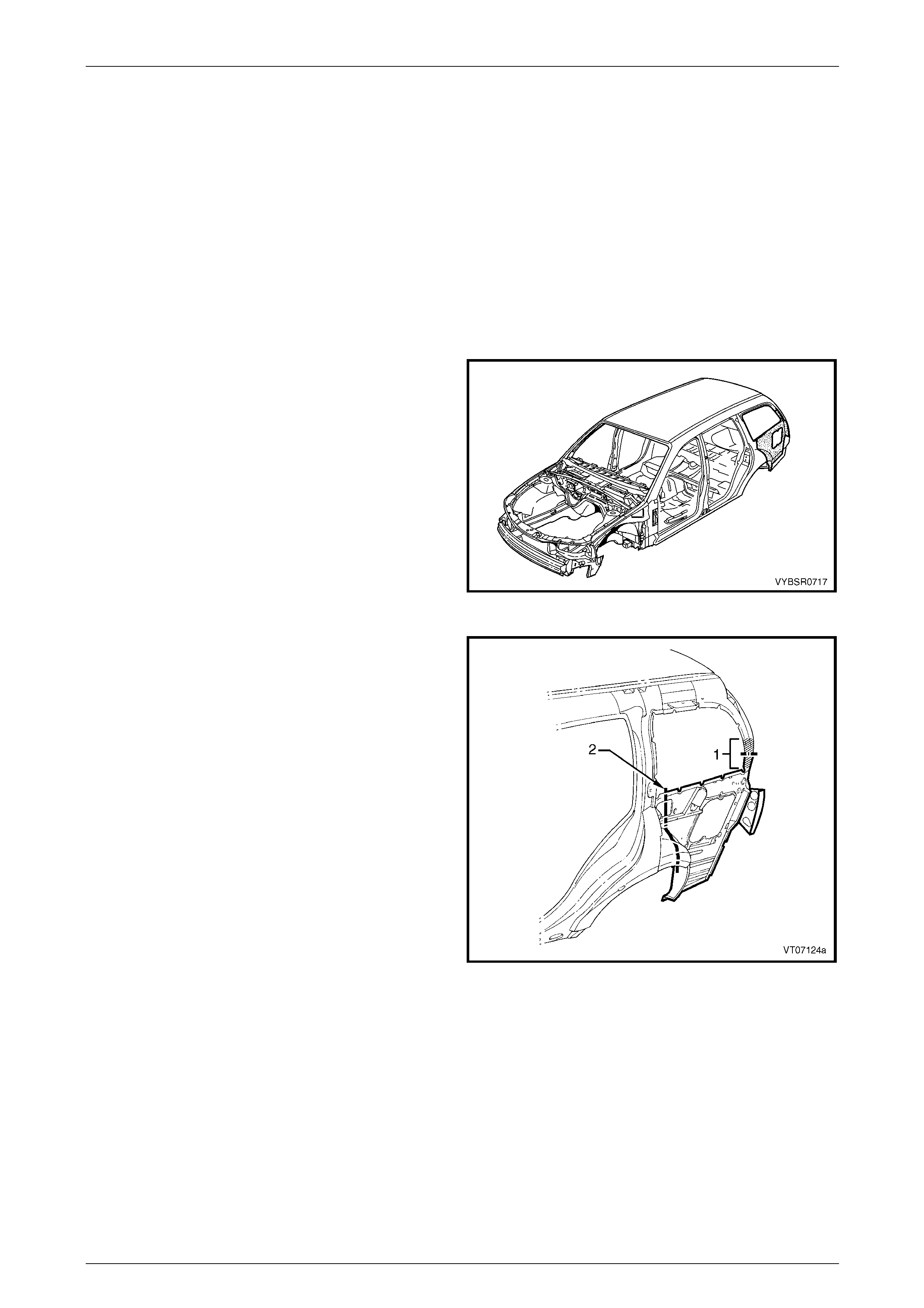
7B Body Side – Wagon Page 7B-64
Page 7B-64
2.13 Quarter Panel Inner Assembly – Partial
Replace
The following procedure allows partial replacement of a rear corner of the wagon without the need to replace the roof
panel or door opening fram e assembly.
If a larger section of the quarter panel inner assembly requires replacing, this can be ach ieved by firstly removing the
partial lock pillar section of the door opening frame assembly.
Refer to 2.8 Door Opening Frame Assembly – Partial Replace, Lock Pillar.
The required partial quarter panel inner assembly replacement can then be performe d using similar techniques to those
in the following operation.
Remove
1 Remove the adjacent bolt-on panels a nd components
as described in the appropriate Section of the MY2005
VZ Service Information.
2 If required, mount the vehicle on a suitable fixture.
Secure a suitable tool bet ween the rear door opening
flanges to maintain alignment once the sections are
removed.
3 Remove rear quarter panel and quarter panel
extension, refer to 2.1 Rear Quarter Panel – Replace
and 2.2 Quarter Panel Exten s ion – Replace.
Figure 7B – 137
4 Cut through the quarter panel inner ass embl y in the
specified region (1) on the back pillar. It is preferable
to cut below the gusset plate where onl y a single
thickness is encountered.
5 Cut through the quarter panel inner assembly
approximately 50 mm behind the door opening frame
(2). This will allow sufficient area for joining of the new
panel section.
Figure 7B – 138
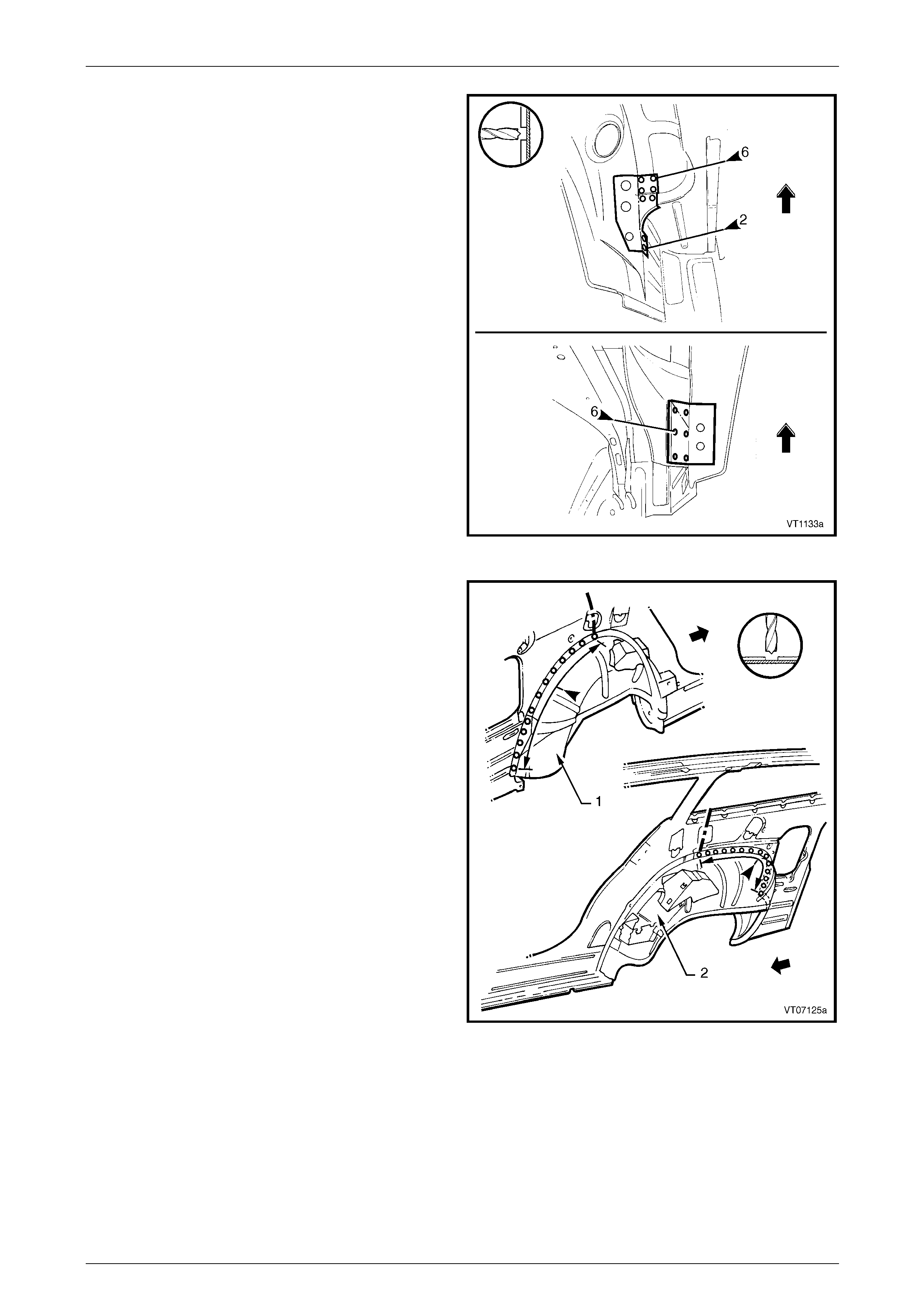
7B Body Side – Wagon Page 7B-65
Page 7B-65
6 Spot cut the welds attaching the rear wheelhouse
reinforcement to the quarter panel inn er asse mbly on
the relevant side.
Figure 7B – 139
7 Spot cut the welds attaching the quarter panel inner
assembly to the rear wheelhouse inner left-h and (1) or
right-hand (2). The spot cutting is onl y required on the
section of the quarter panel inner assem bl y being
removed.
8 Spot cut the welds attaching the rear compartment
floor assembly to the quarter panel inn er asse mbly on
the side being removed. Refer to Figure 7B – 141.
9 Spot cut the welds attaching the quarter inner lower
rear extension to the rear end panel e xtension.
Figure 7B – 140
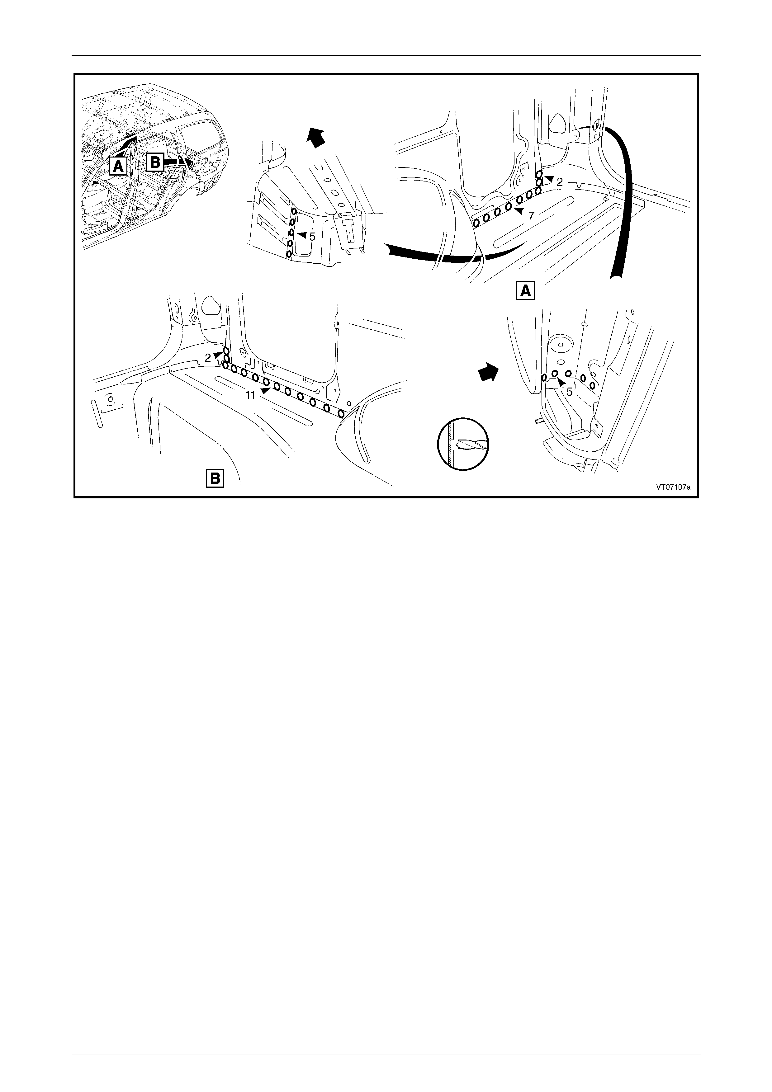
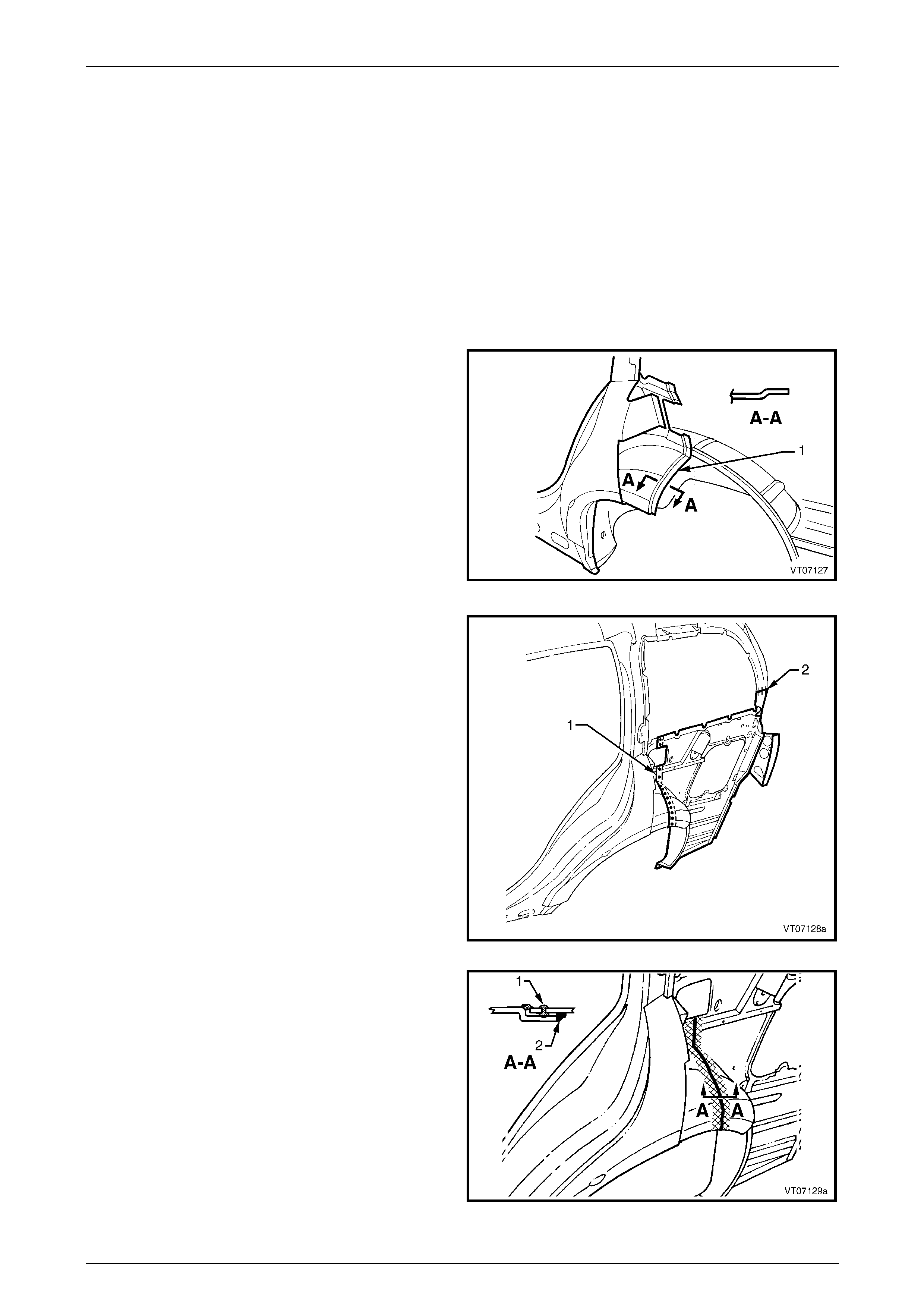
7B Body Side – Wagon Page 7B-67
Page 7B-67
Replace
NOTE
• Spot welding is the preferred method for
attaching of panels and should be used
whenever possible. Where the spot welding
equipment available will not access the
required weld position, a plug weld should be
performed.
• The same number and position of spot welds
(or plug welds) should be used when
replacing the panel, as was used during
manufacture, in order to maintain the original
structural strength of the vehicle.
1 Joggle the edge of the remaining q uarter panel inner
assembly and outer wheelho use (1) towards the inside
of the vehicle. Size the joggle for an overlap of
approximately 30 mm.
2 Cut a replacement quarter panel inner section from a
new panel assembly. T he new pan el should be
measured and cut accurately to overlap the joggled
panel in the wheelhous e area and to line up for a butt
weld in the back pillar area.
3 Mark the new panel with drilling locations where
required, in preparation for pl ug welding. Drill holes as
marked.
4 Prepare all mating surfaces and treat with Weld
Through Primer (Item 1) as required, refer to
Section 3B Body Construction – Wagon. Figure 7B – 142
5 Spot or plug weld the replacement section al ong the
join (1). Perform welds at a maximum spacing of
35 mm along the length of the join.
6 Butt weld the new panel section to the vehicle across
the back pillar join (2).
Figure 7B – 143
7 Complete the joint around the wheelhouse by MIG
welding (1) on the outer side of the pan el.
Figure 7B – 144
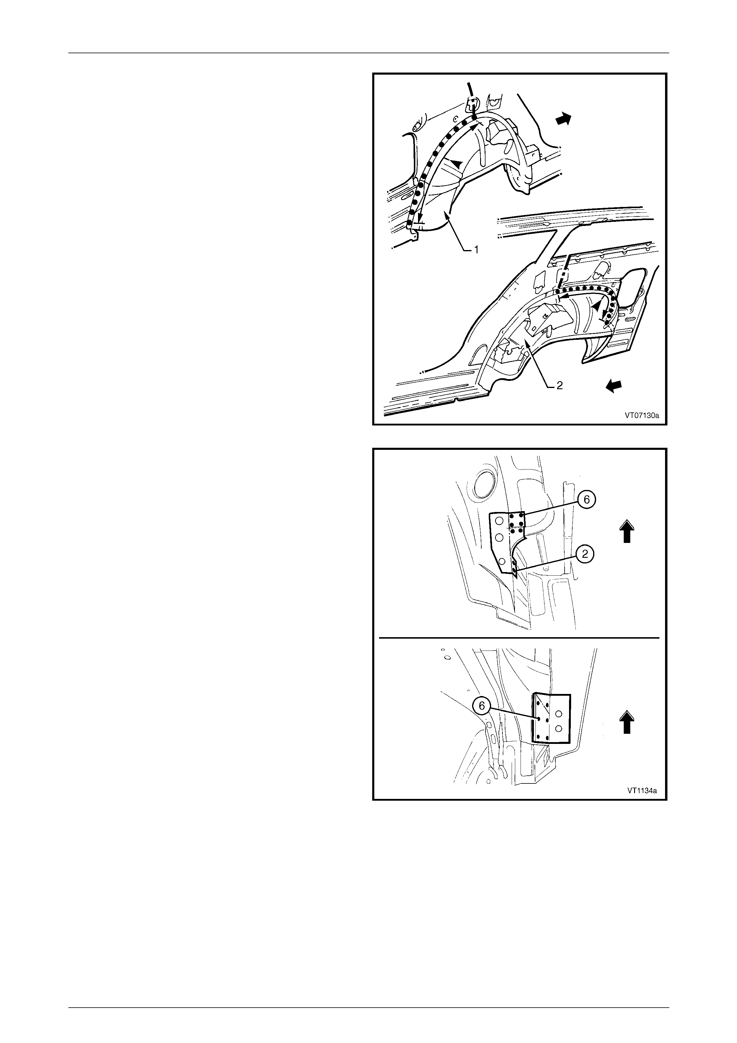
7B Body Side – Wagon Page 7B-68
Page 7B-68
8 Weld the quarter panel inner t o the rear wheelhouse
inner, either left-hand (1) or right-hand (2).
Figure 7B – 145
9 Spot or plug weld the rear wheelhous e reinforcement
to quarter panel inner.
10 Spot or plug weld the quarter panel in ner to the rear
compartment floor assembly, refer to Figure 7B – 147.
NOTE
The welds along the rear compartment floor
assembly rear of the wheelhouse also attach the
quarter outer lower rear panel, which can be
replaced now, also refer to 2.4 Quarter Outer
Lower Rear Panel – Replace.
11 Weld the quarter panel inner lower extension to the
rear end panel extension.
Figure 7B – 146
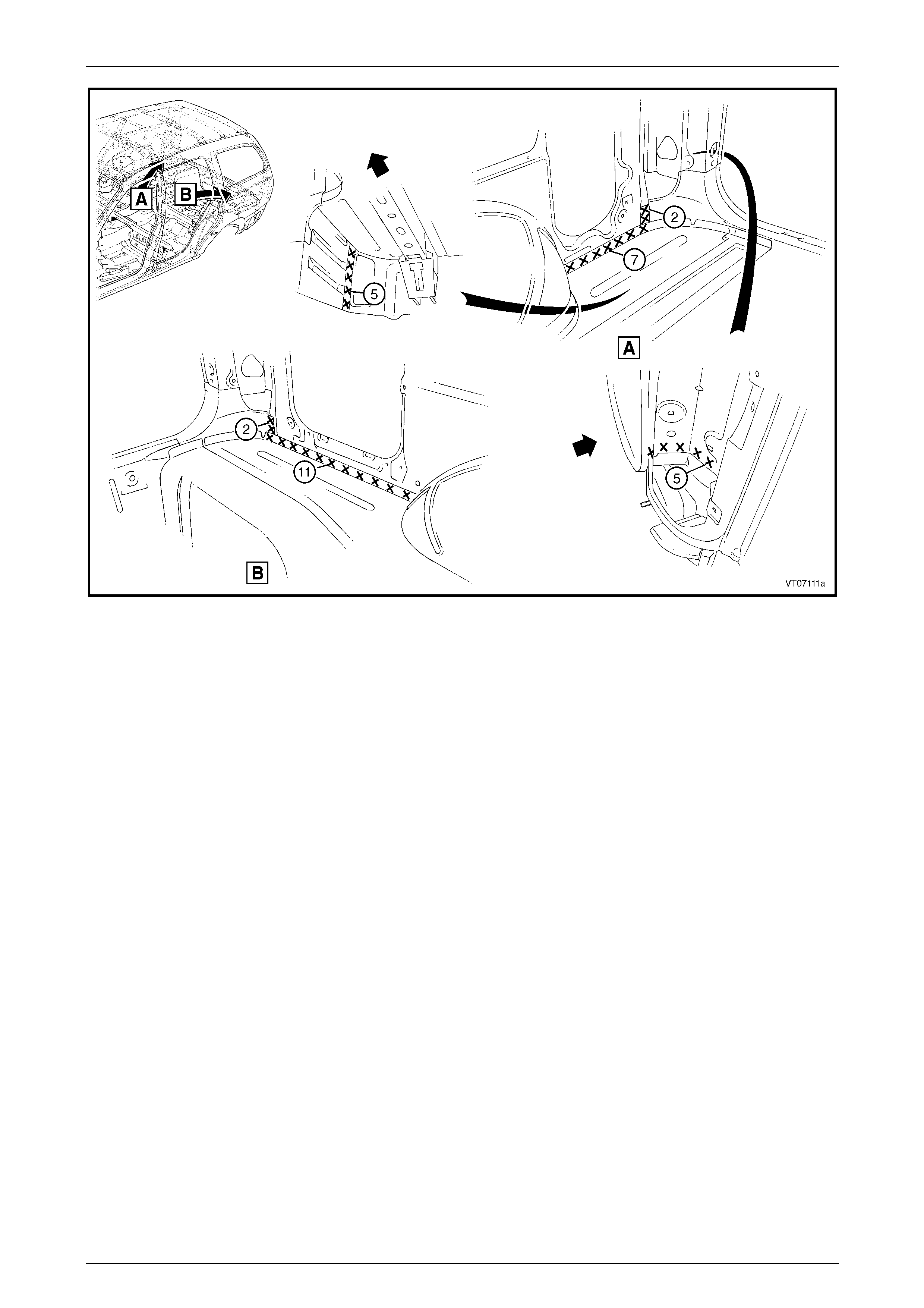
7B Body Side – Wagon Page 7B-69
Page 7B-69
Figure 7B – 147
12 Replace the rear quarter panel and quarter panel extension, refer to 2.1 Rear Quarter Panel – Replace and
2.2 Quarter Panel Extension – Replace.
13 Refinish and paint panels and other components as required. Refer to Section 3 Body Construction.
14 Apply Joint Sealer (Item 3) as required. Refer to Section 3B Body Construction – Wagon.
15 Apply Cavity Wax (Item 8) as required to the inside of any box secti ons or areas inaccessible to paint,
refer to Section 3B Body Construction – Wagon.
16 Apply spray-on deadener to the wheel side of the wheelhouse, refer to Section 3B Body Construction – Wagon.
17 Install the remaining components as described in the appr opriate Section of the MY2005 VZ Service Information.

7B Body Side – Wagon Page 7B-70
Page 7B-70
3 Torque Wrench Specifications
Dash Panel Retaining Bolt.........................................................35.0 – 45.0 Nm