
7C Body Side – Utility Page 7C-1
Page 7C-1
Section 7C
Body Side – Utility
ATTENTION
Before performing any service operation or other procedure described in this Section, refer to Section 2
Precautions in this Supplement and Section 00 Warnings, Cautions and Notes in the MY2005 VZ Service
Information for correct workshop practices with regard to safety and/or property damage.
The structure of the body shell has been
developed using complex design and
development techniques. In addition to
meeting all required standards, the vehicle
body is also a critical part of the overall safety
systems. It is therefore imperative the repair
procedures described here are adhered to
during all vehicle body repairs.
1 General Description ...............................................................................................................................3
1.1 Body Side Components ........................................................................................................................................ 3
2 Service Operations.................................................................................................................................5
2.1 Rear Quarter Panel – Replace............................................................................................................................... 5
Remove................................................................................................................................................................... 5
Replace................................................................................................................................................................... 8
2.2 Quarter Panel Extension – Replace.................................................................................................................... 11
Remove................................................................................................................................................................. 11
Replace................................................................................................................................................................. 13
2.3 Quarter Panel Inner Lower Rear Extension – Replace ..................................................................................... 15
Remove................................................................................................................................................................. 15
Replace................................................................................................................................................................. 16
2.4 Quarter Outer Lower Rear Panel – Replace....................................................................................................... 17
Remove................................................................................................................................................................. 17
Replace................................................................................................................................................................. 18
2.5 Quarter Lower Rear Panel – Replace ................................................................................................................. 20
Replace................................................................................................................................................................. 21
2.6 Door Opening Frame Assembly – Replace........................................................................................................ 22
Remove................................................................................................................................................................. 22
Replace................................................................................................................................................................. 26
2.7 Door Opening Frame Assembly – Partial Replace, Hinge Pillar...................................................................... 32
Remove................................................................................................................................................................. 32
Replace................................................................................................................................................................. 35
2.8 Door Opening Frame Assembly – Partial Replace, Centre Pillar..................................................................... 40
Remove................................................................................................................................................................. 40
Replace................................................................................................................................................................. 42
2.9 Door Opening Frame Assembly – Partial Replace, Rocker Panel................................................................... 46
Remove................................................................................................................................................................. 46
Replace................................................................................................................................................................. 49

7C Body Side – Utility Page 7C-2
Page 7C-2
2.10 Fender Lower Rear Bracket – Replace............................................................................................................... 53
2.11 Hinge Pillar Inner Panel Assembly – Replace ................................................................................................... 54
Remove................................................................................................................................................................. 54
Replace................................................................................................................................................................. 56
2.12 Quarter Inner and Rear Wheelhouse Brace – Replace ..................................................................................... 59
Replace................................................................................................................................................................. 59
2.13 Quarter Panel Inner Assembly – Replace.......................................................................................................... 61
Remove................................................................................................................................................................. 61
Replace................................................................................................................................................................. 64
2.14 Side Inner Upper Panel – Replace...................................................................................................................... 67
Remove................................................................................................................................................................. 67
Replace................................................................................................................................................................. 70
2.15 Side Inner Upper Panel – Partial Replace.......................................................................................................... 73
Remove................................................................................................................................................................. 73
Replace................................................................................................................................................................. 74
2.16 Side Inner Upper Front Panel – Replace............................................................................................................ 76
Remove................................................................................................................................................................. 76
Replace................................................................................................................................................................. 77
2.17 Load Floor Panel Outer Extension and Load Floor Panel Outer Reinforcement – Replace.......................... 79
Replace................................................................................................................................................................. 80
2.18 Rear Wheelhouse Inner Panel – Replace........................................................................................................... 82
Remove................................................................................................................................................................. 82
Replace................................................................................................................................................................. 84
3 Torque Wrench Specifications............................................................................................................87
7C Body Side – Utility Page 7C-3
Page 7C-3
1 General Description
This Section describes the replacement procedures for the body side components of the Utility body structure. Removal
of bolt-on panels and mechanic al components is not covered.
When repairing the body side of the vehicle, care must be taken to ensure the structure is returned to its original
production configuration. This is especially important to maintain side impact standards and for the veh icle’s occupant
protection system to operate correctly.
This Section includes door opening frame assembly partial r eplacement procedures for the hinge pillar, centre pillar, and
rocker panel. These procedures must be followed carefully, as they regula rly involve hidden reinforcement pane ls. The
cutting locations specified are the only places allowable.
NOTE
• It is imperative the correct body adhesives,
sealers, deadeners and cavity waxes are
used when repairing th e body structure. Refer
to Section 3C Body Construction – Util ity.
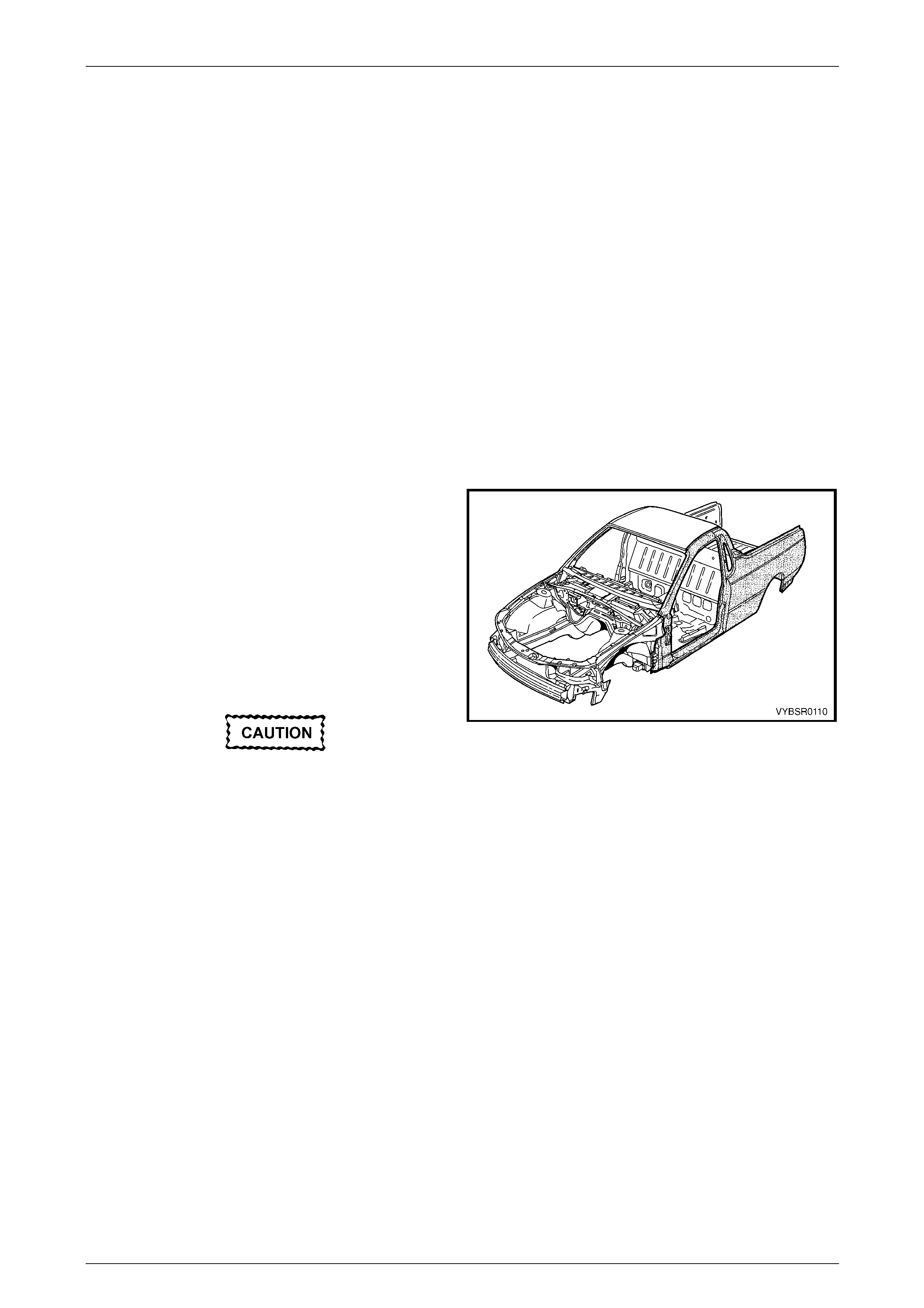
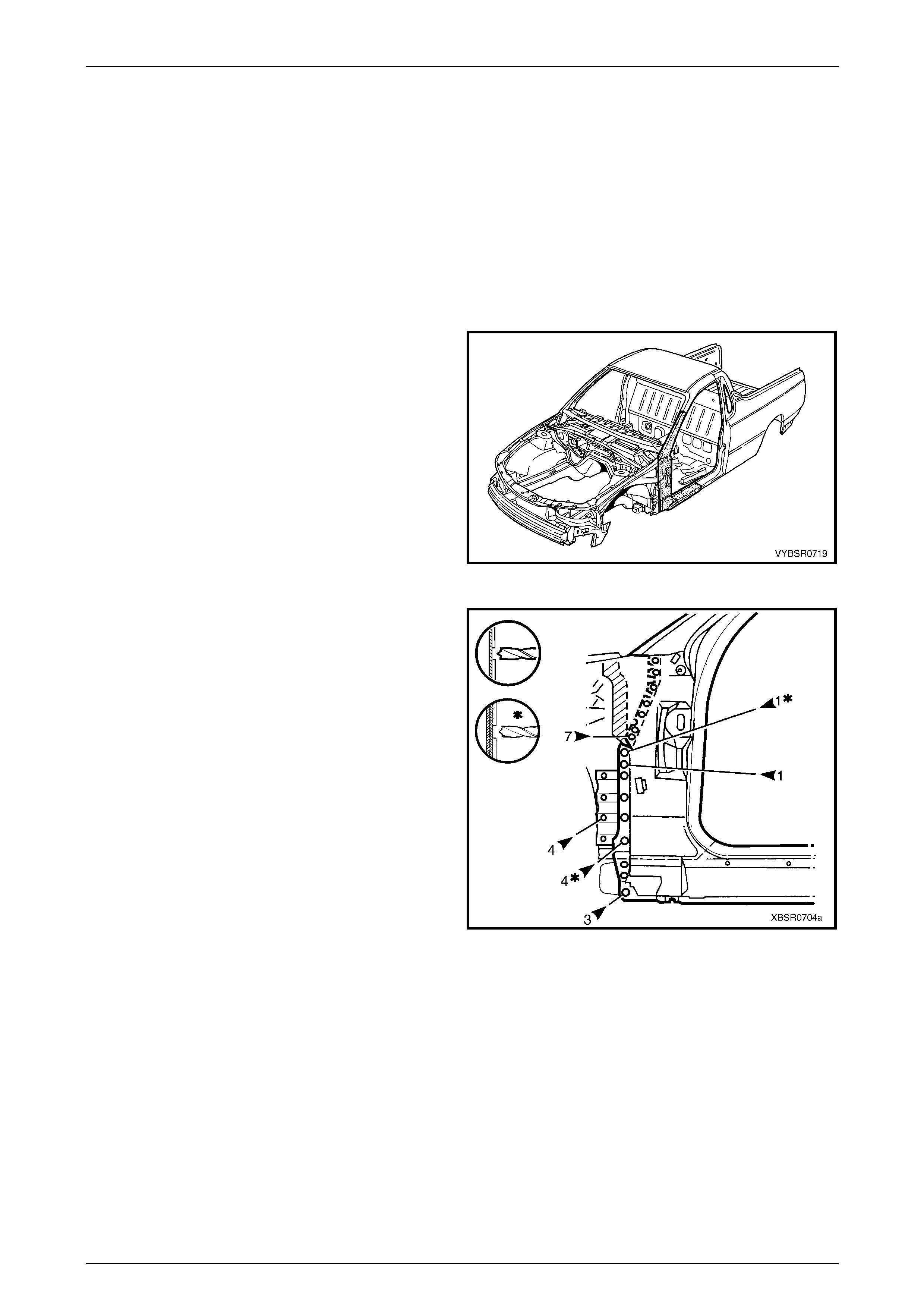
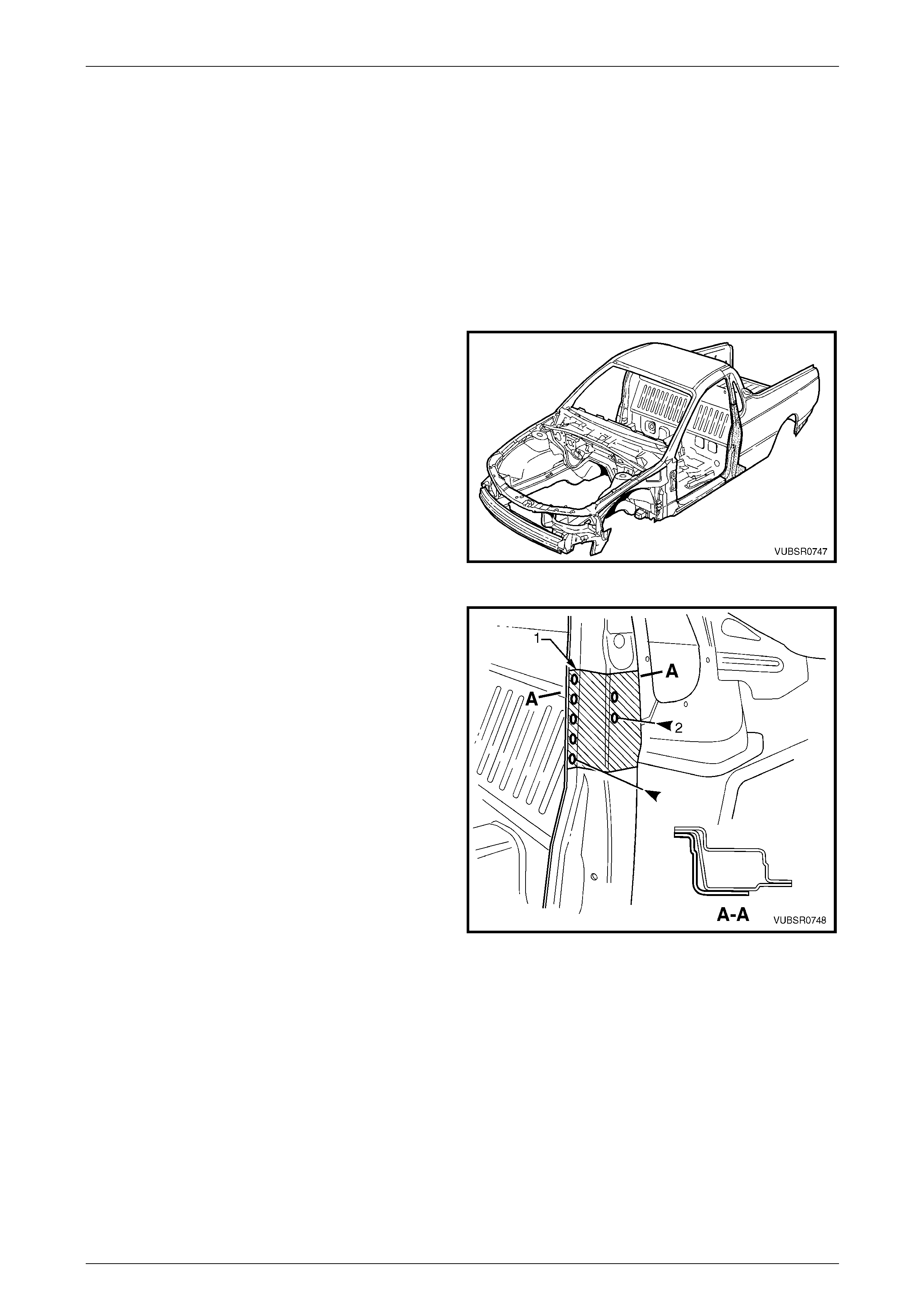
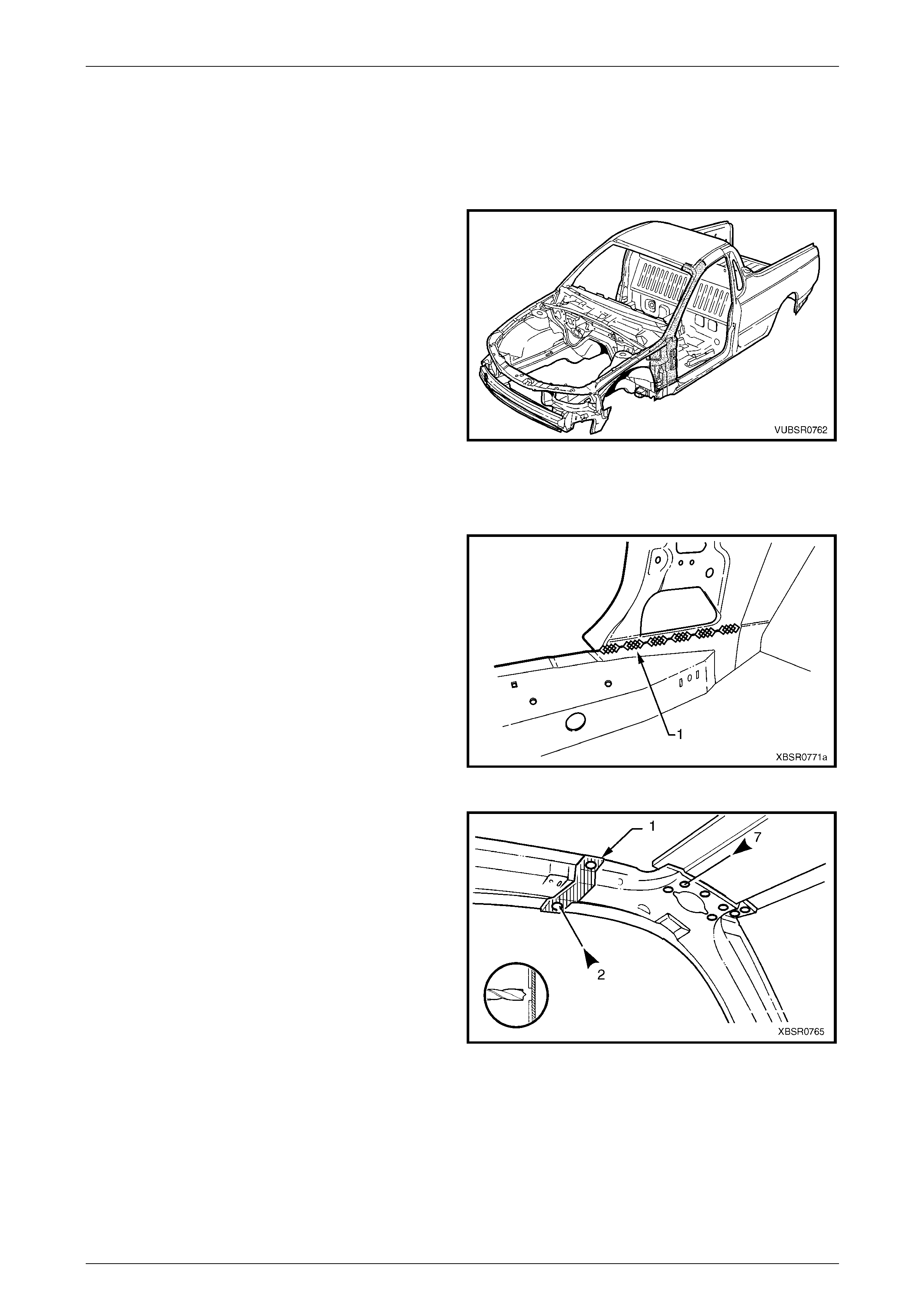
1.1 Body Side Components
The shaded components in Figure 7C – 1 are those dealt
with in this Section.
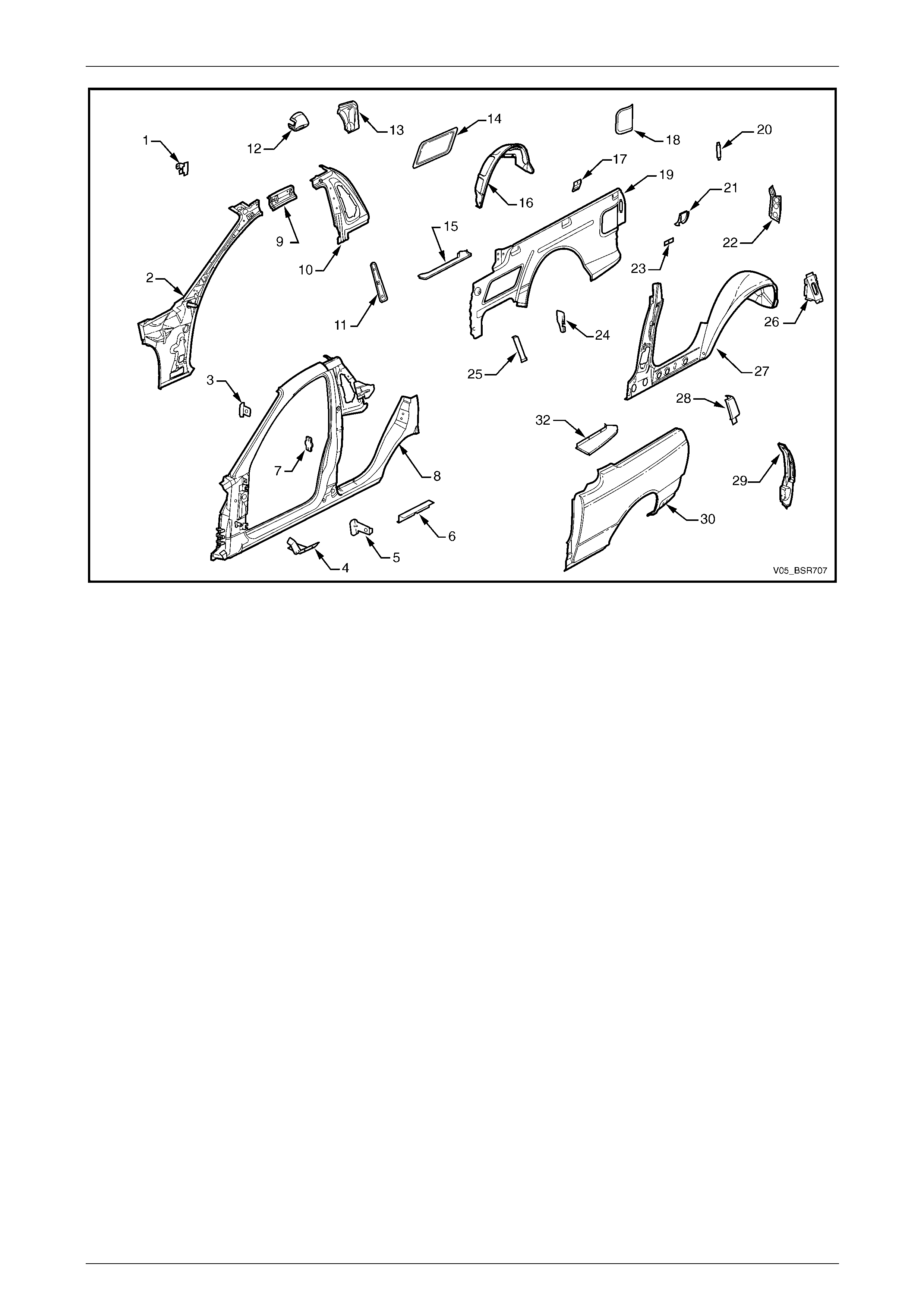
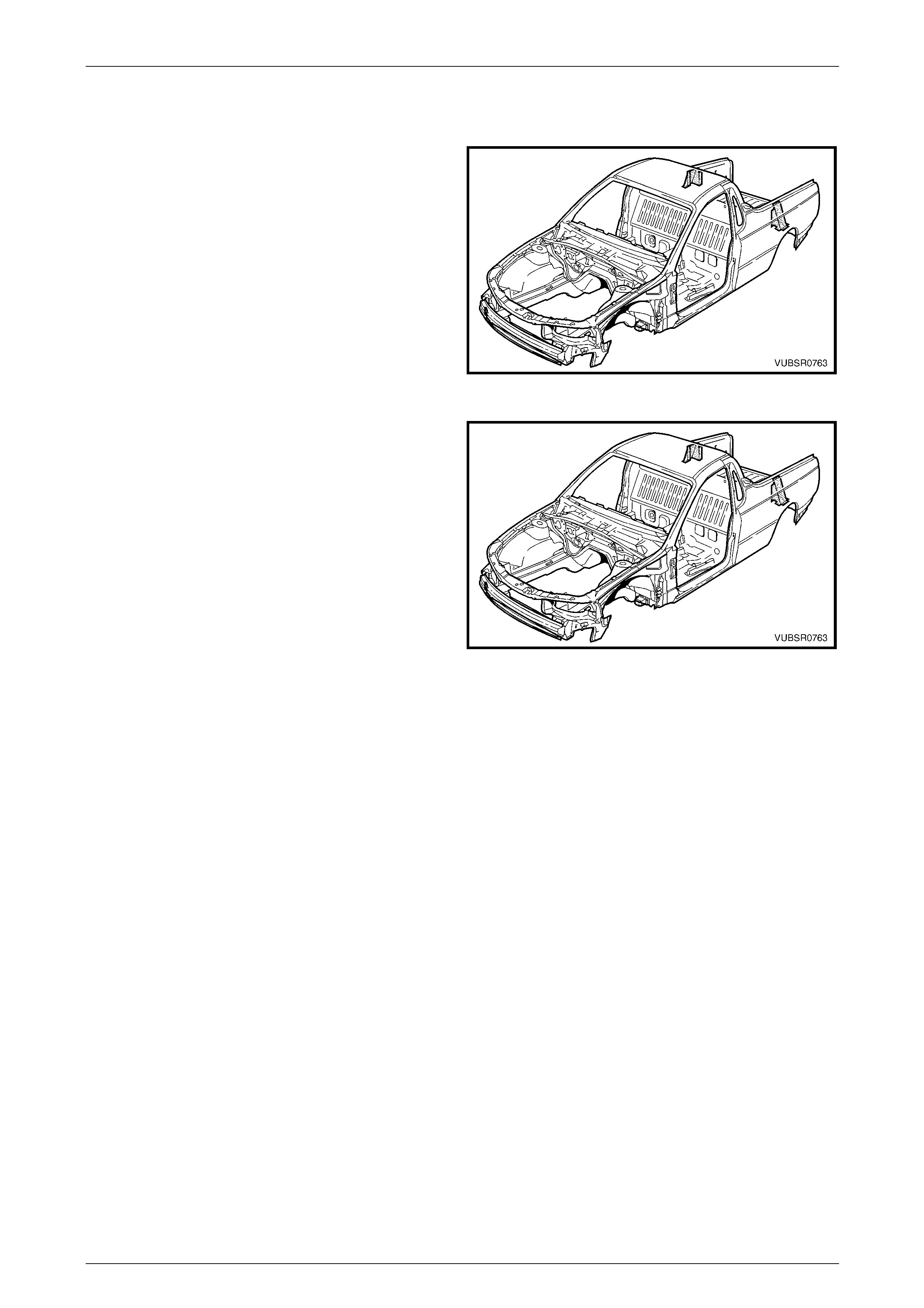
The components and assemblies shown in Figure 7C – 2
are the serviceable parts that form the basis of the repair
procedures in this Section. For a detailed view of the body
components, refer to Section 3C Body Construction – Utility.
NOTE
Always refer to an Authorised Retailer for spare
parts availability configurations.
Cavity foam may be used within the hinge
and centre. Care needs to be taken when
repairing the vehicle in these areas, refer to
Section 2 Precautions prior to beginning any
work for further information regarding the
use of cavity foam.
Figure 7C – 1
7C Body Side – Utility Page 7C-4
Page 7C-4
Figure 7C – 2
Legend
1 Hinge Pillar Trim Panel Bracket, Left-hand / Right-hand
2 Hinge Pillar Inner Panel Assembly, Left-hand / Right-hand
3 Fender Upper Rear Bracket, Left-hand / Right-hand
4 Fender Lower Rear Bracket, Left-hand / Right-hand
5 Fender Rear Bracket, Left-hand / Right-hand
6 Underbody Jacking Locator, Left-hand / Right-hand
7 Front Door Striker Anchor Plate, Left-hand / Right-hand
8 Door Opening Frame Assembly, Left-hand / Right-hand
9 Quarter Panel Inner Extension, Left-hand / Right-hand
10 Side Inner Upper Front Panel, Left-hand / Right-hand
11 Seatbelt Guide Anchor Plate Assembly, Left-hand / Right-
hand
12 Fuel Filler Pipe Housing, Right-hand
13 Rear Wheelhouse Outer Extension, Right-hand
14 Front Inner Side Panel Cover, Left-hand / Right-hand
15 Load Floor Panel Outer Extension, Left-hand / Right-hand
16 Rear Wheelhouse Inner Panel, Left-hand / Right-hand
17 Cargo Tie-down Bracket, (three places), Left-hand / Right-
hand
18 Rear Inner Side Panel Cover, Left-hand / Right-hand
19 Side Inner Upper Panel, Left-hand / Right-hand
20 Endgate Striker Anchor Plate Retainer, Left-hand / Right-
hand
21 Quarter Lower Rear Panel, Left-hand / Right-hand
22 Quarter Inner Lower Rear Extension, Left-hand / Right-hand
23 Cargo Tie-down Bracket Anchor Plate Assembly, (three
places), Left-hand / Right-hand
24 Rear Wheelhouse Bracket, Left-hand / Right-hand
25 Load Floor Panel Outer Reinforcement, Left-hand / Right-
hand
26 Quarter Inner and Rear Wheelhouse Brace, Left-hand /
Right-hand
27 Quarter Panel Inner Assembly, Left-hand / Right-hand
28 Quarter Panel Upper Extension, Left-hand / Right-hand
29 Quarter Panel Extension, Left-hand / Right-hand
30 Rear Quarter Panel, Left-hand / Right-hand
31 Quarter Outer Lower Rear Panel, Left-hand / Right-hand
NOTE
• The door opening frame assembly (8)
includes parts 3, 4, 5, 6 and 7.
7C Body Side – Utility Page 7C-5
Page 7C-5
2 Service Operations
2.1 Rear Quarter Panel – Replace
The fuel tank is located under the load floor
front panel. To avoid the possibility of fire,
remove the fuel tank and plug all lines when
grinding, cutting or welding.
NOTE
The rear body wirin g harness is routed behind the
right-hand quarter pa nel; take care not to damage
or burn the harness.
Remove
1 Remove the adjacent bolt-on panels a nd components
as described in the appropriate Section of the MY2005
VZ Service Information.
2 Remove the rear and quarter window, refer to
Section 1A6 Stationary Windows in the MY2005 VZ
Service Information.
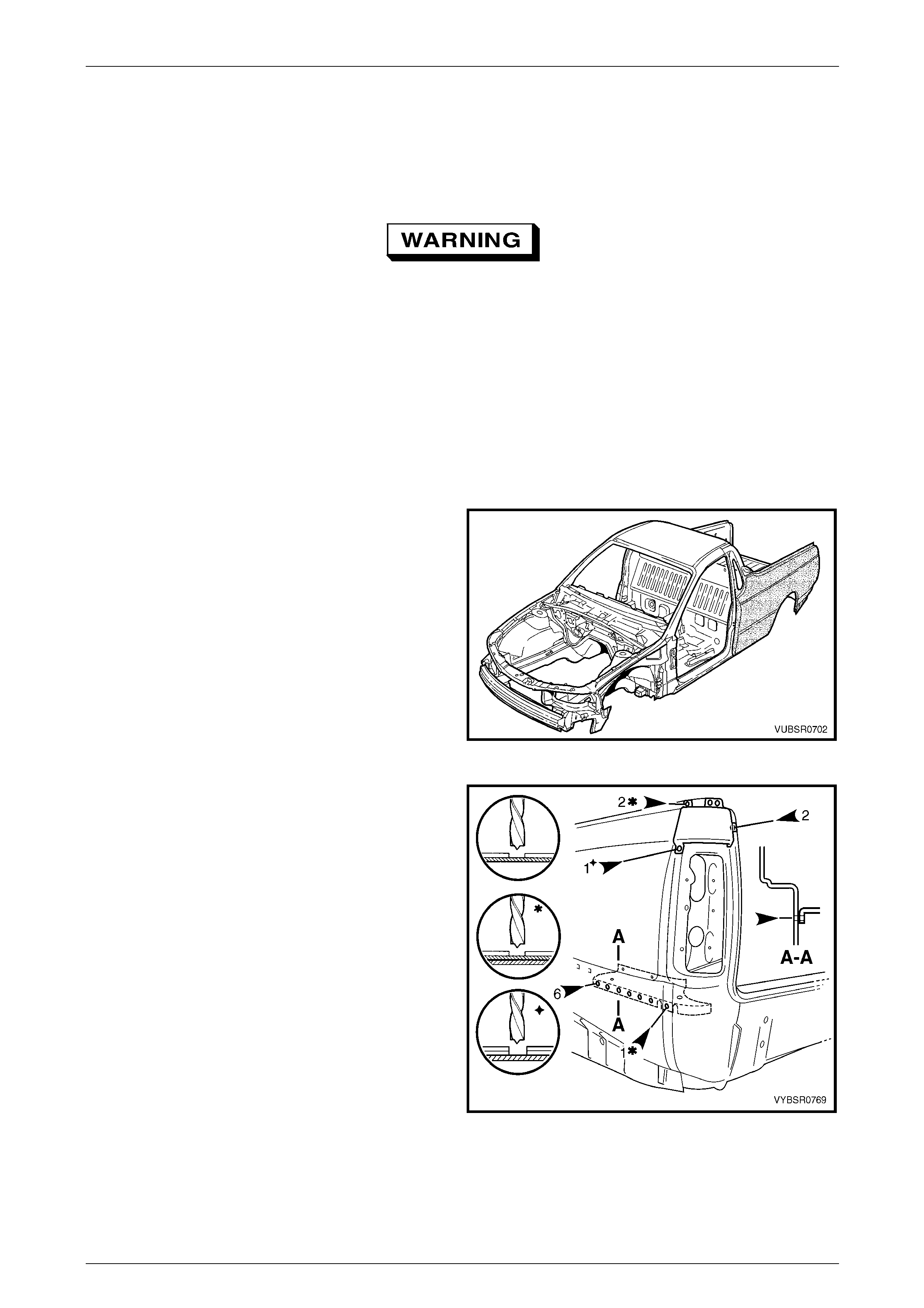
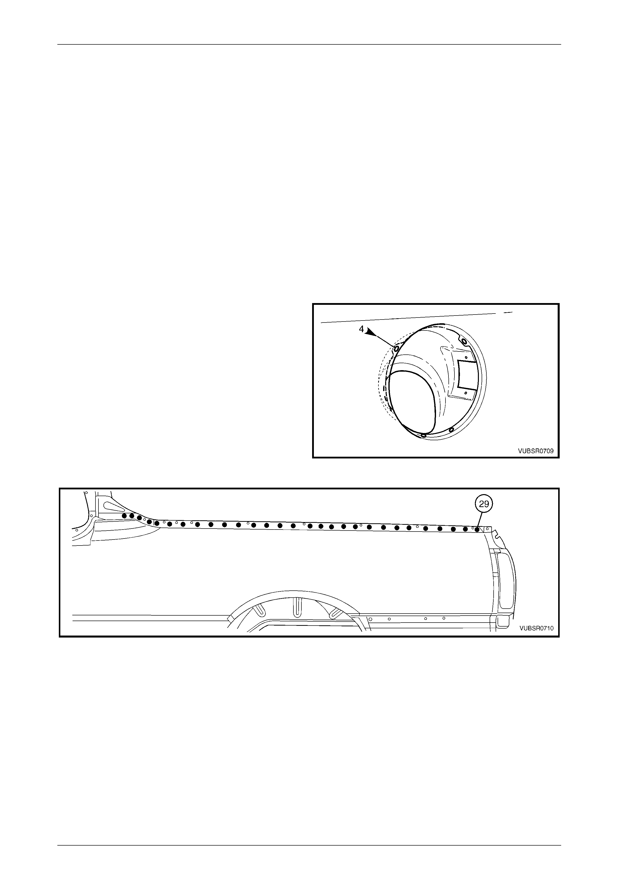
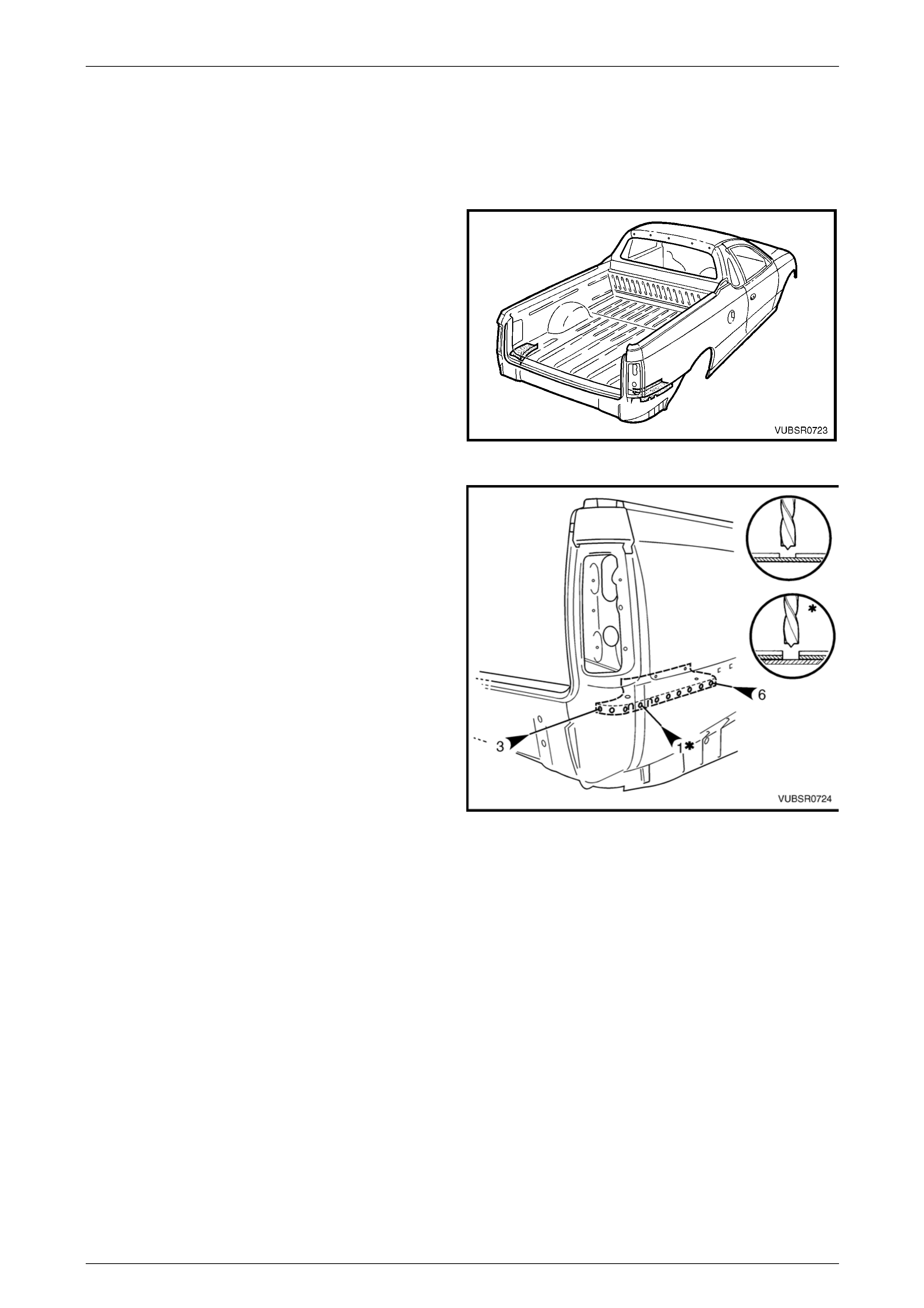
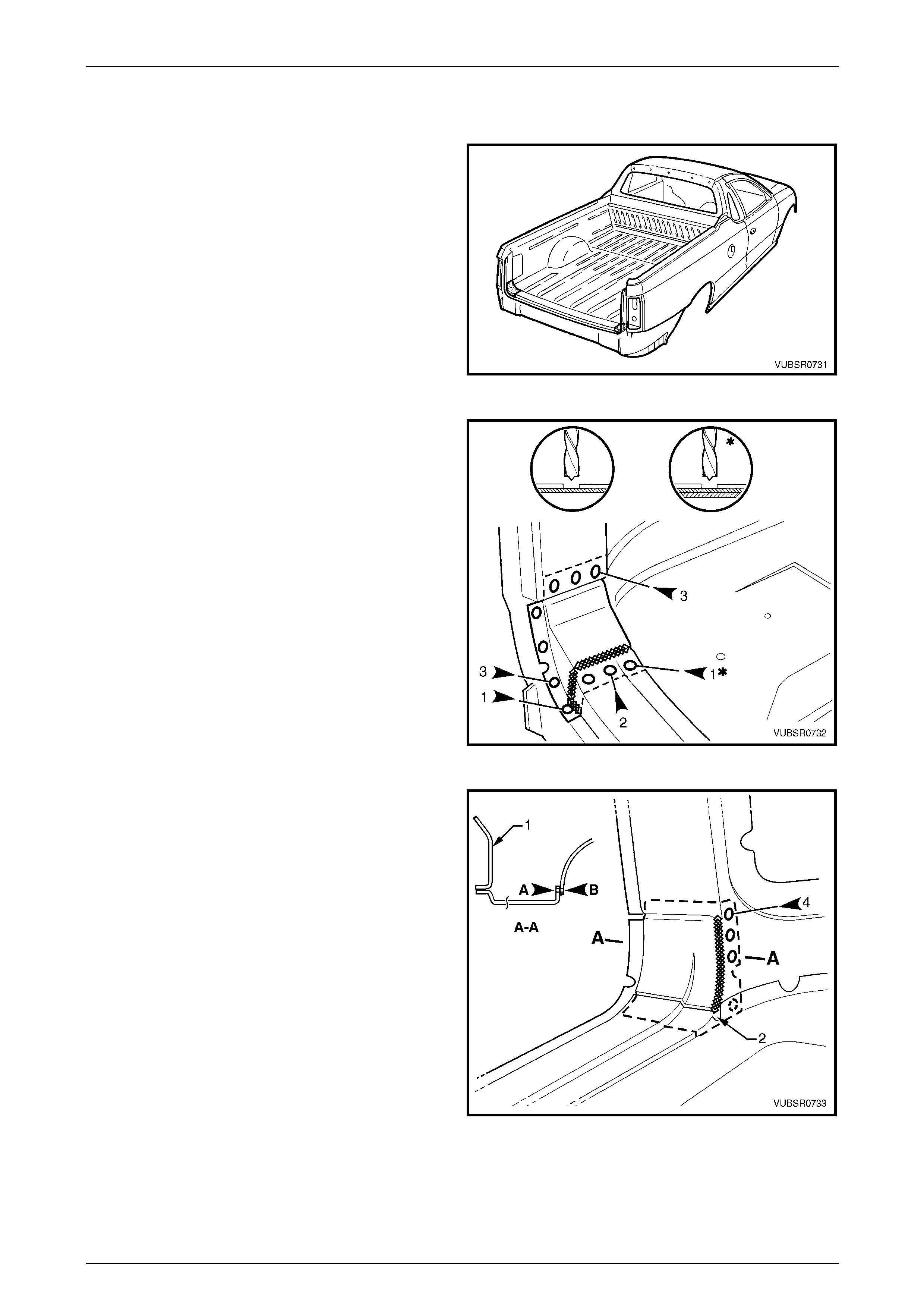
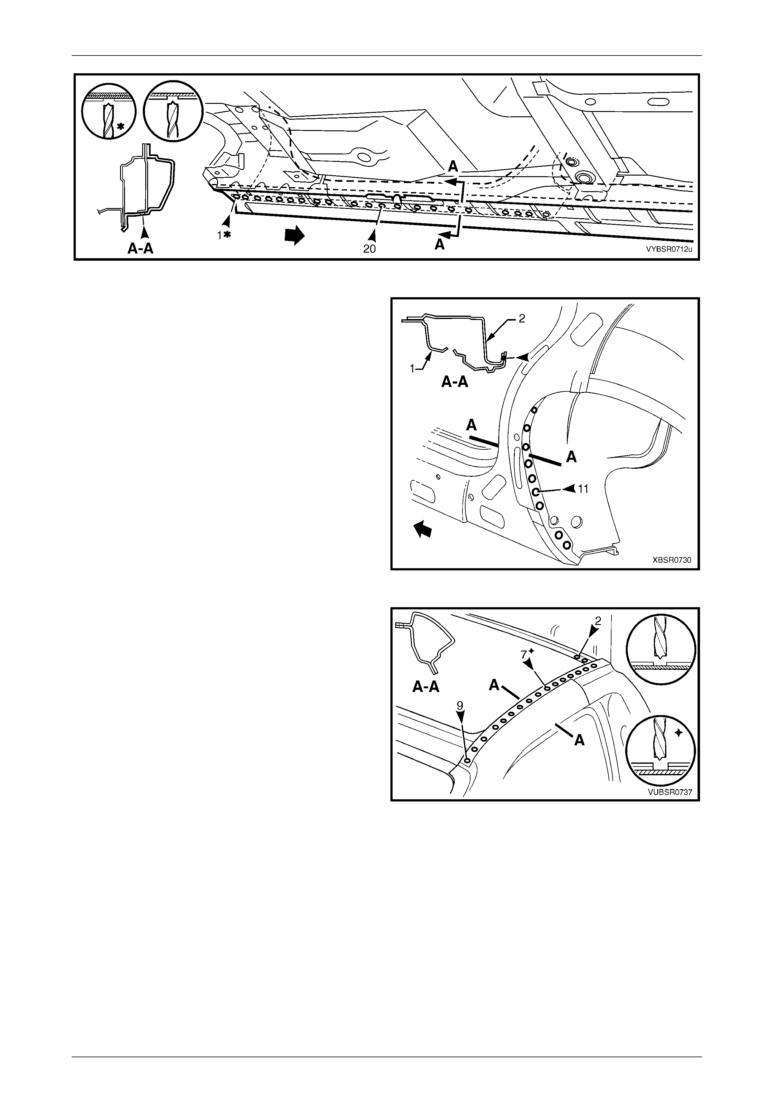
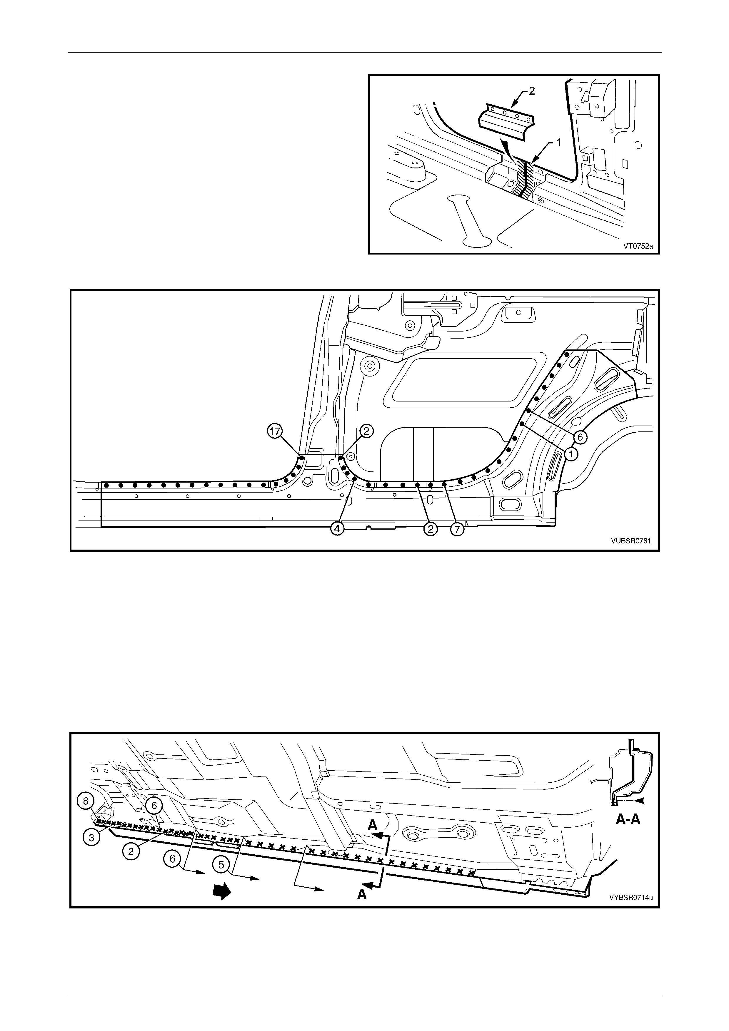
Figure 7C – 3
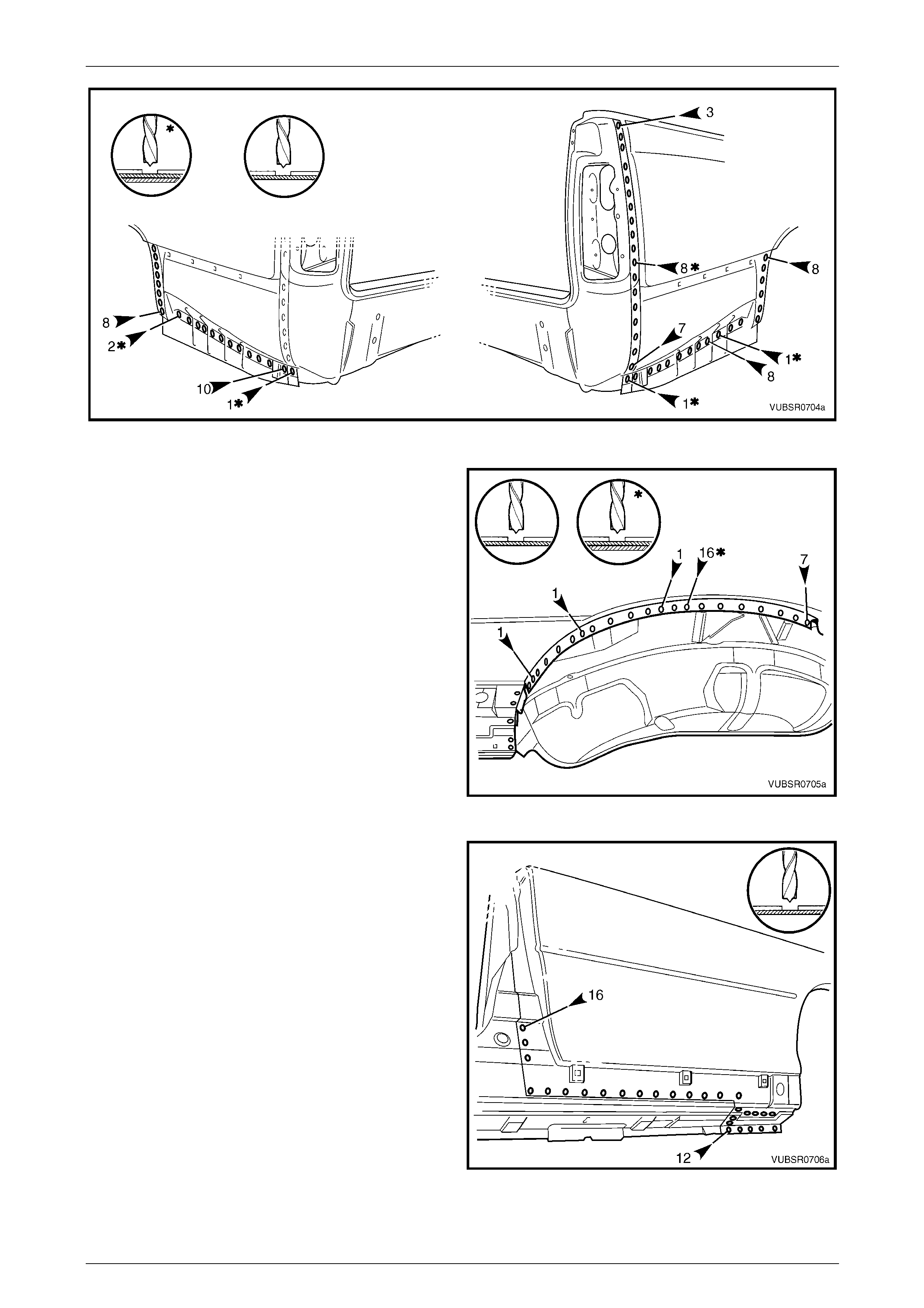
3 To access the spot welds underneath, the quarter
panel upper extension will require removal. Spot cut:
• two welds attaching it to the quarter panel
extension,
• two welds attaching it to the quarter panel
extension and side inner upper panel,
• one weld attaching it and the rear qu arter panel
to the quarter panel extension.
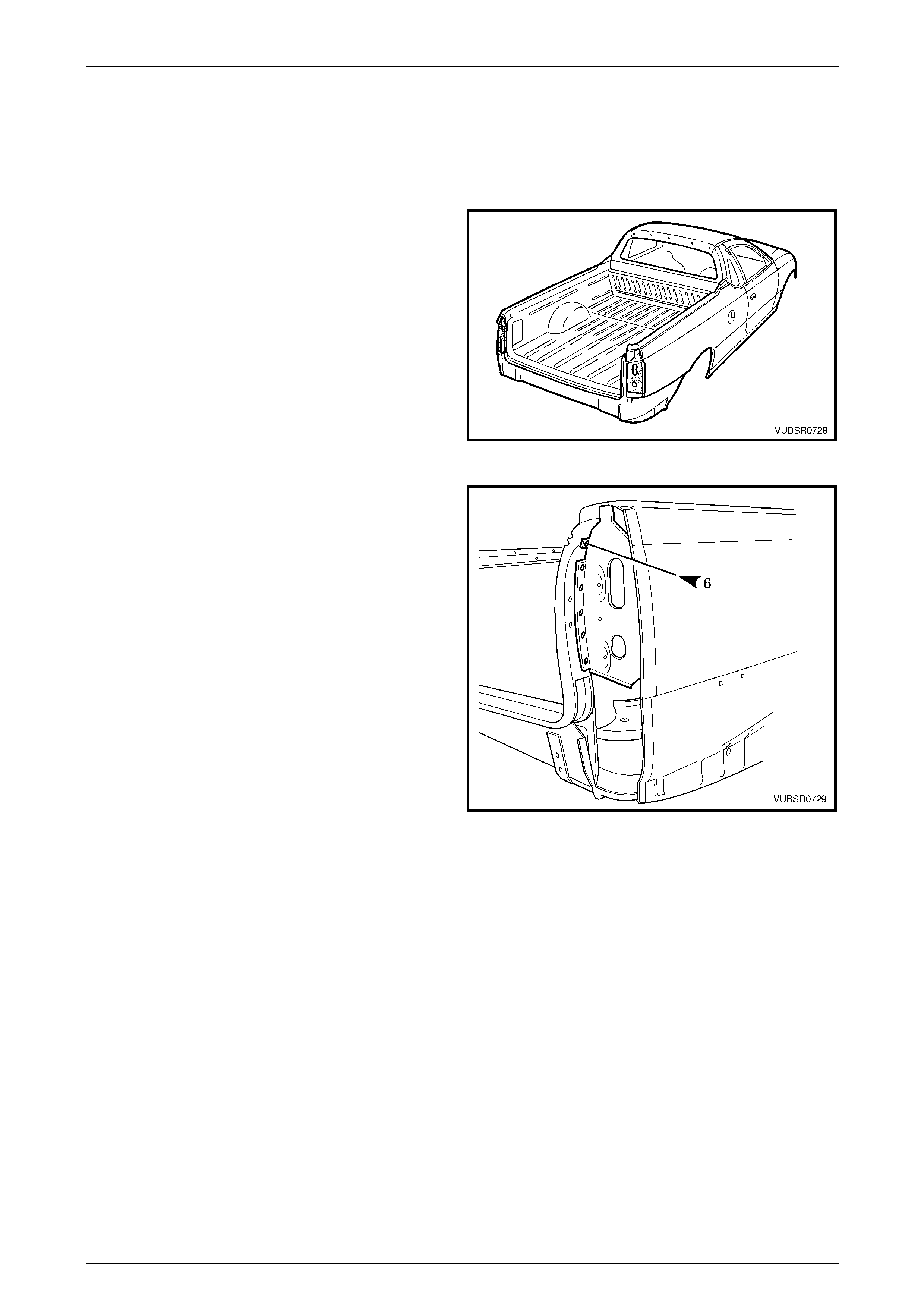
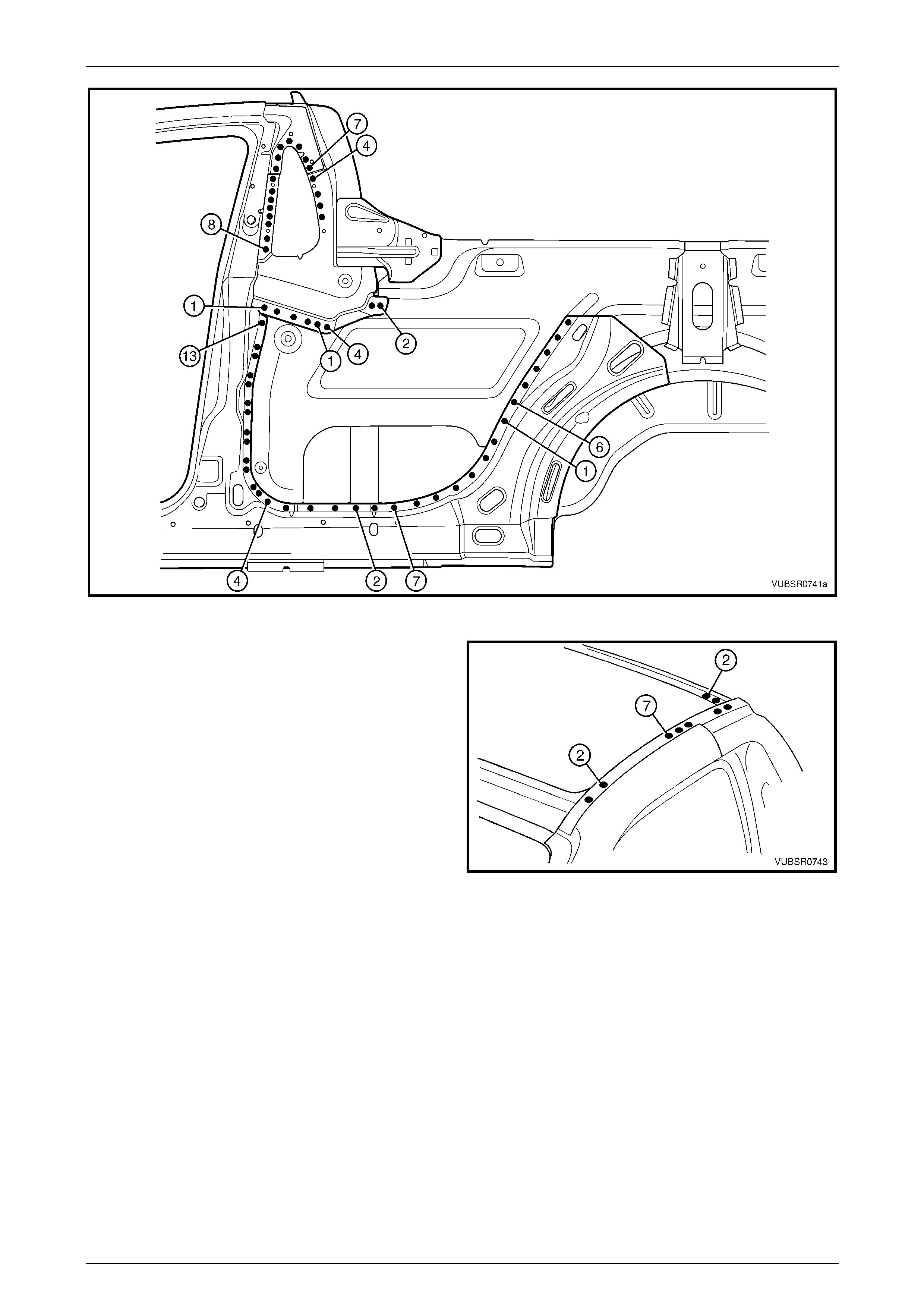
4 Spot cut the six welds attaching the rear quarter pane l
to the quarter outer lower rear panel.
5 Spot cut the weld attaching the rear quarter panel and
quarter panel extension to the quarter outer lower rear
panel.
6 Spot cut the welds attaching the rear quarter panel as
shown in Figure 7C – 5. Note differences between left-
hand and right-hand sides. Figure 7C – 4
7C Body Side – Utility Page 7C-6
Page 7C-6
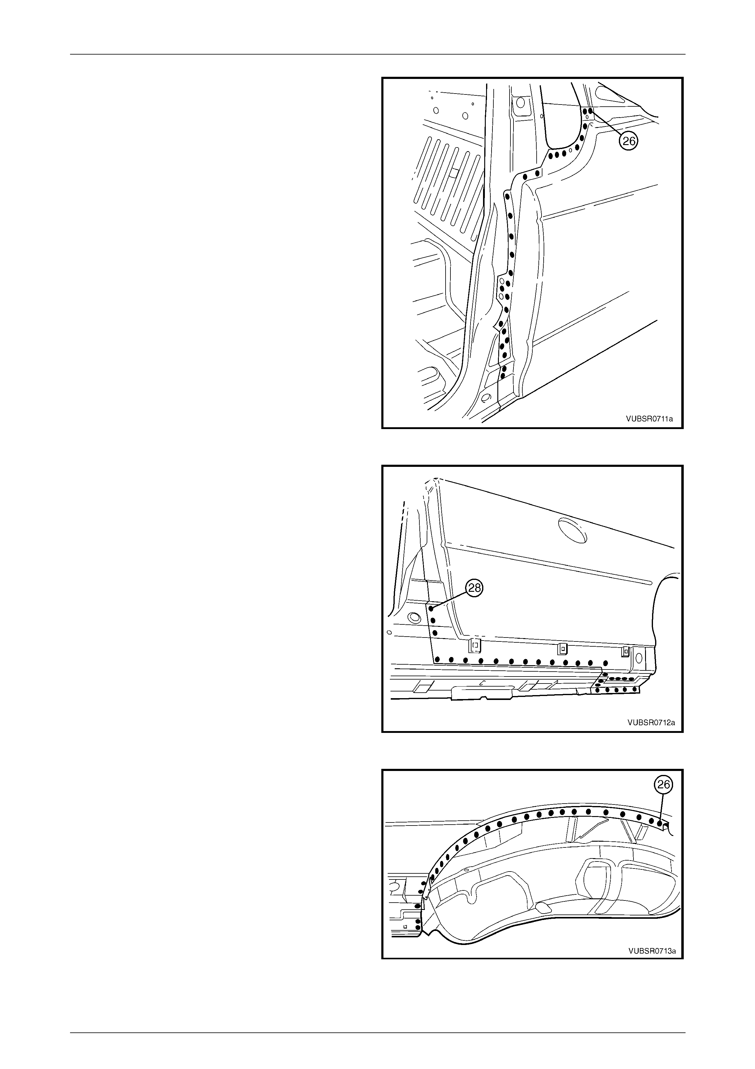
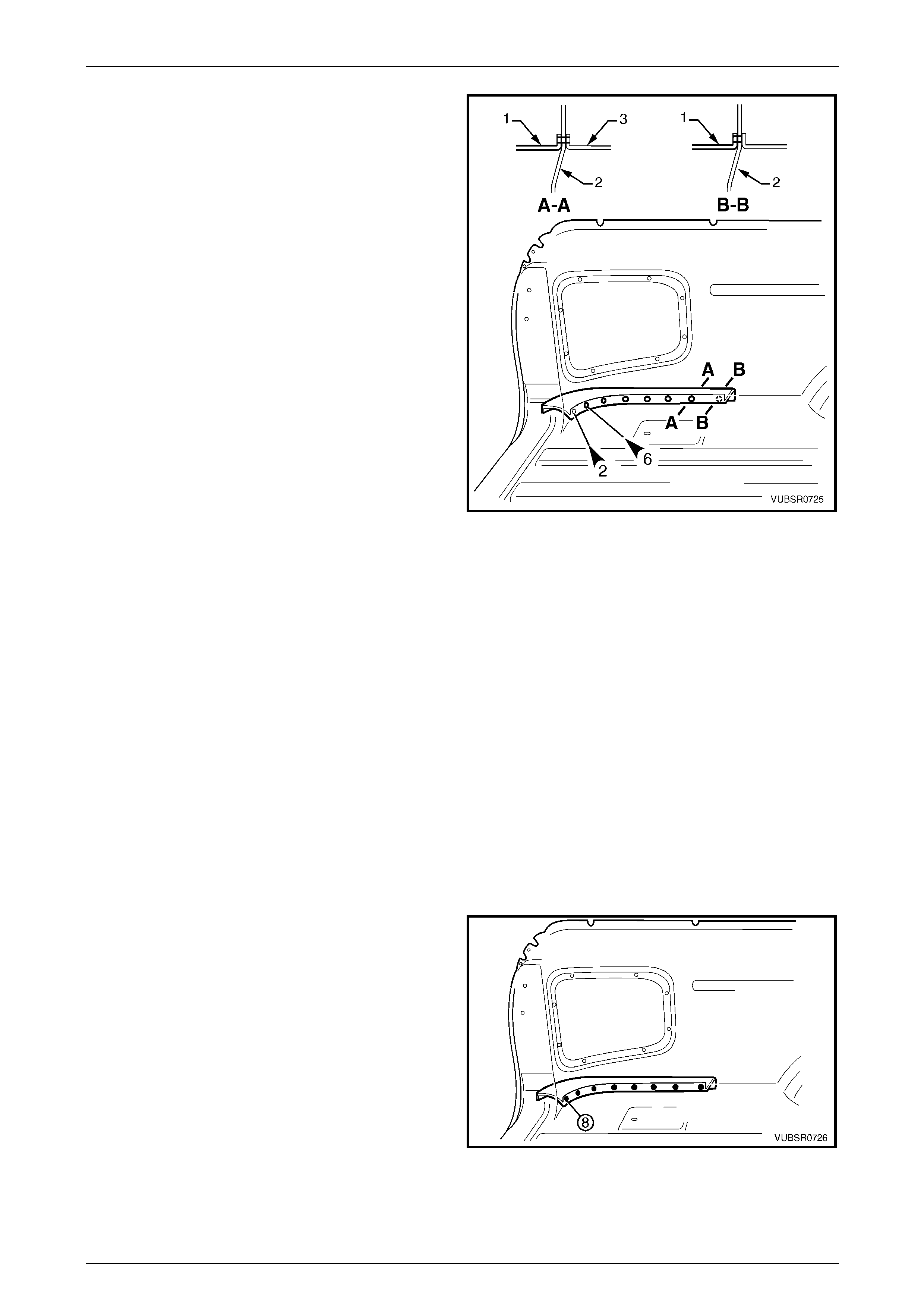
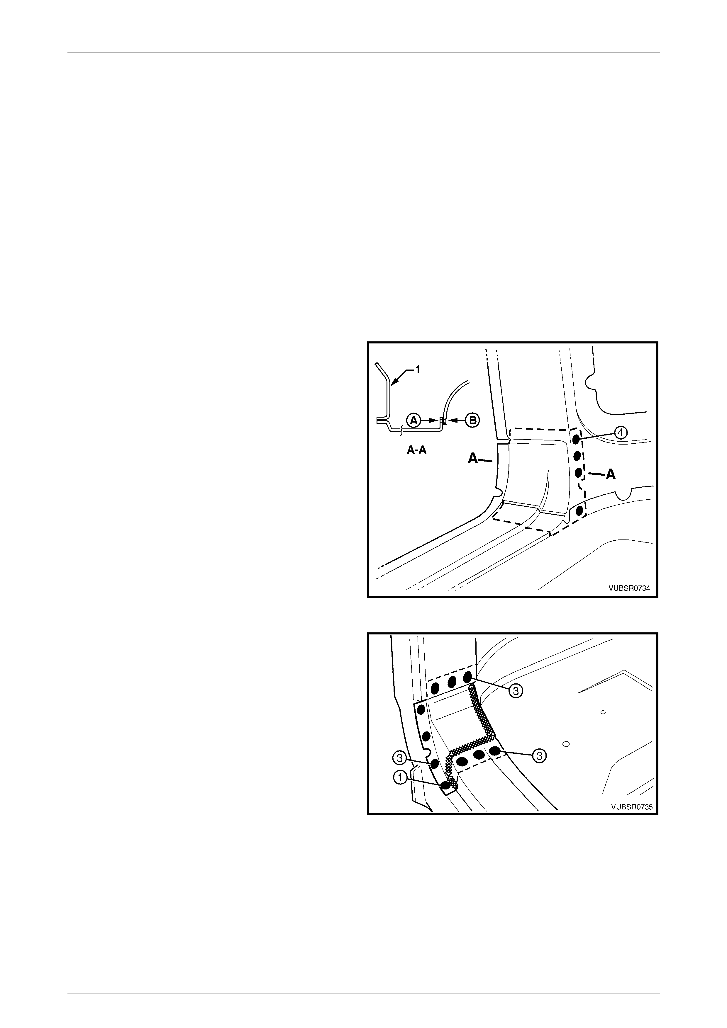
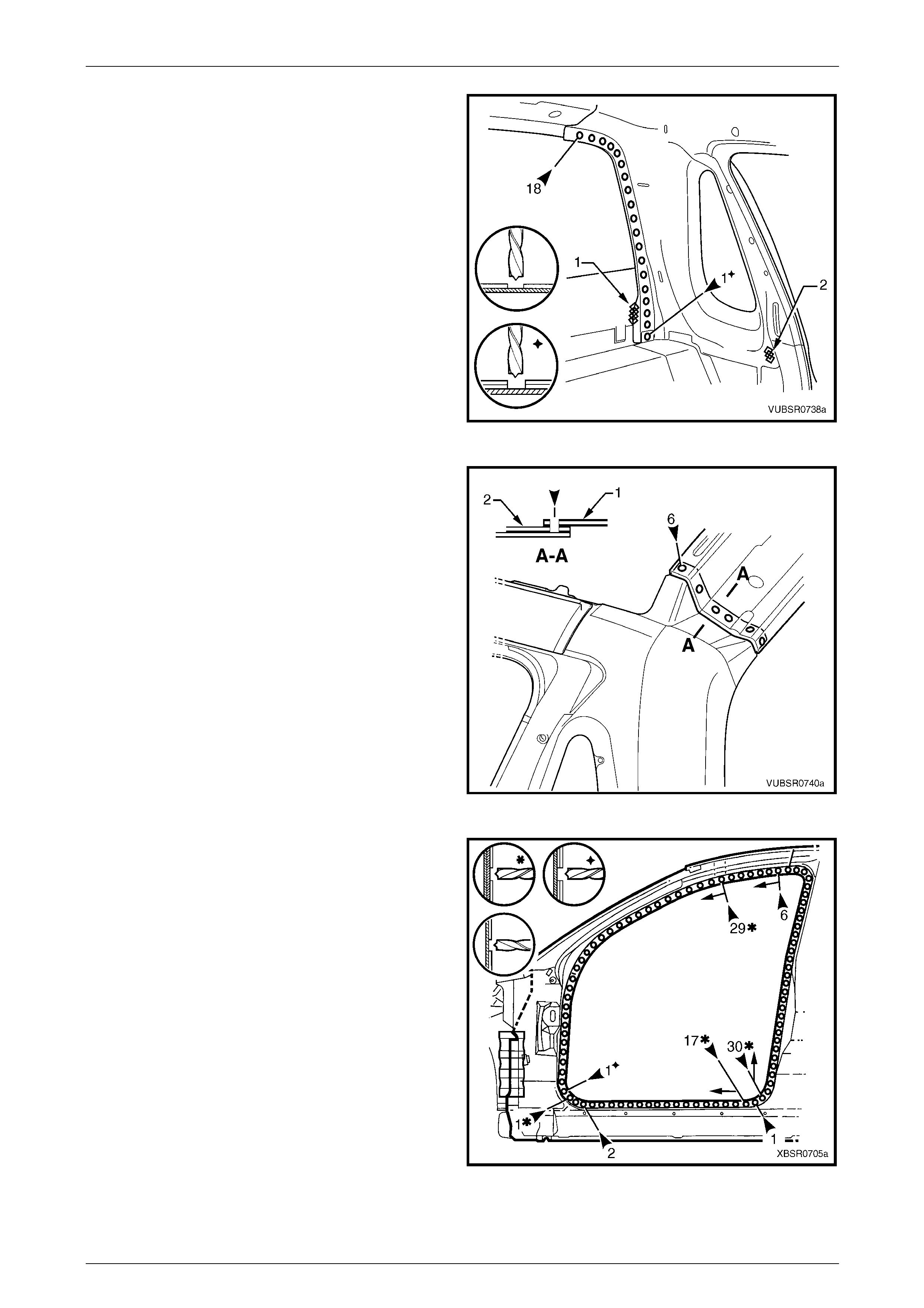
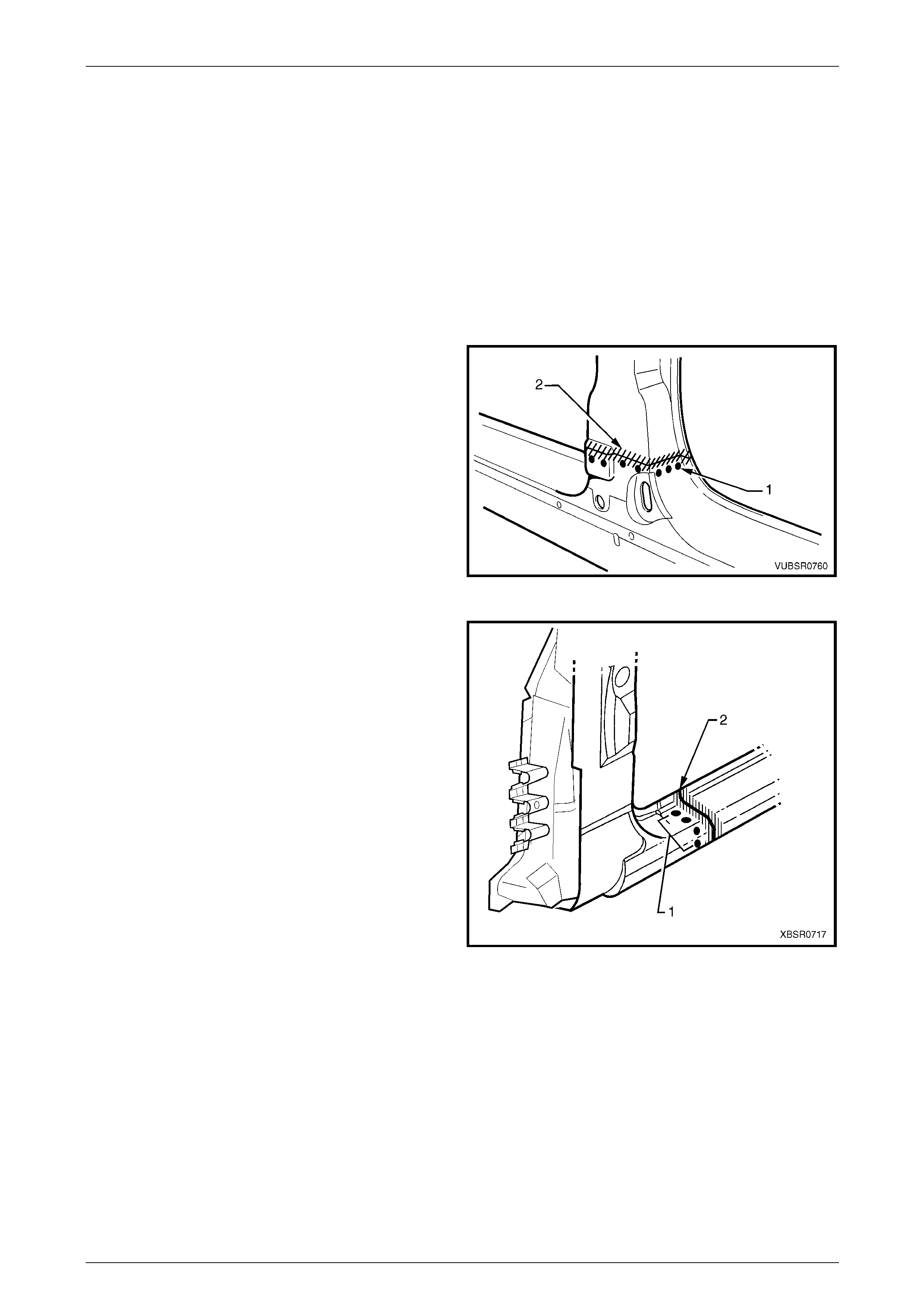
Figure 7C – 5
7 Spot cut the welds around the wheel arch opening
attaching the rear quarter panel to the d oor opening
frame assembly and quarter panel inn er asse mbly.
Figure 7C – 6
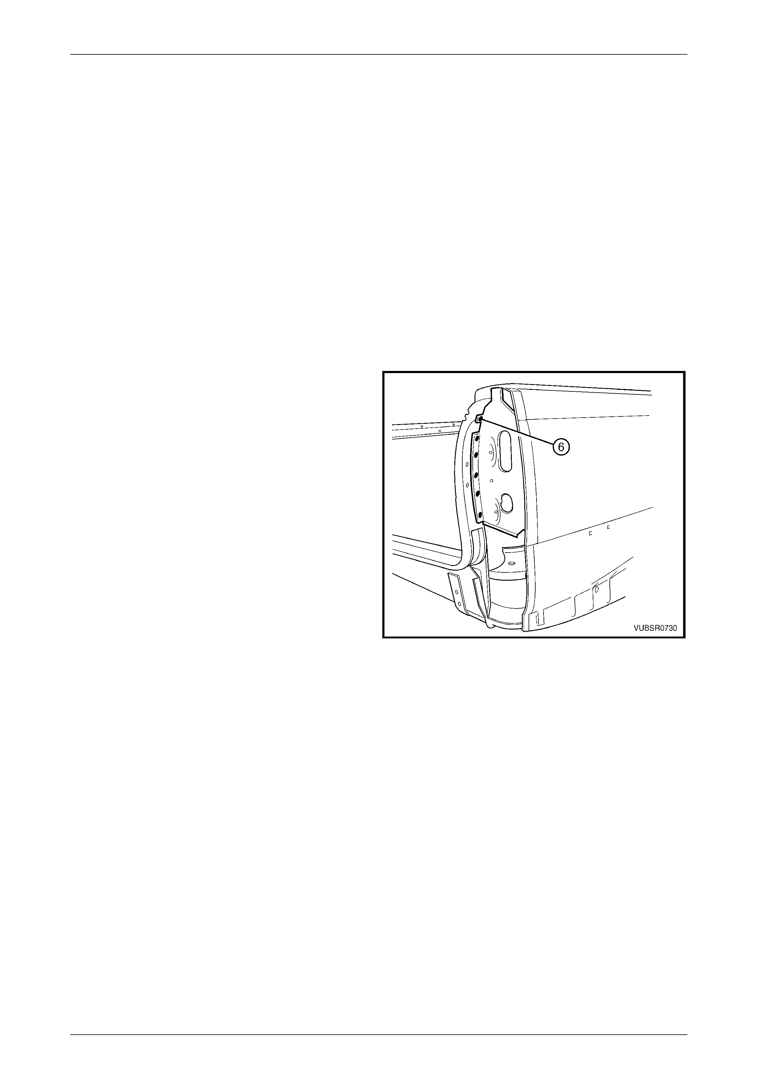
8 Spot cut the welds attaching the rear quarter panel to
the door opening frame assembly.
Figure 7C – 7

7C Body Side – Utility Page 7C-7
Page 7C-7
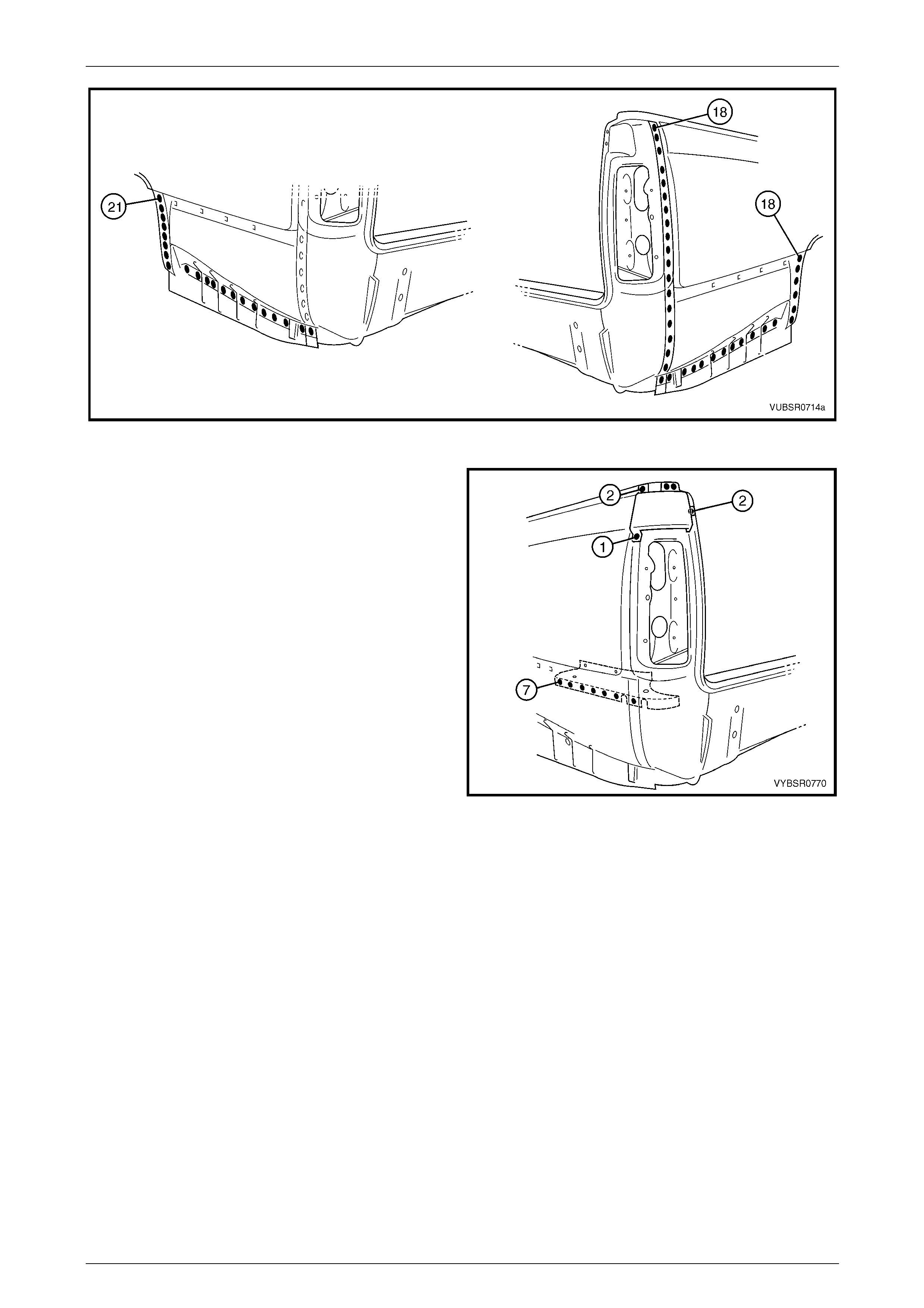
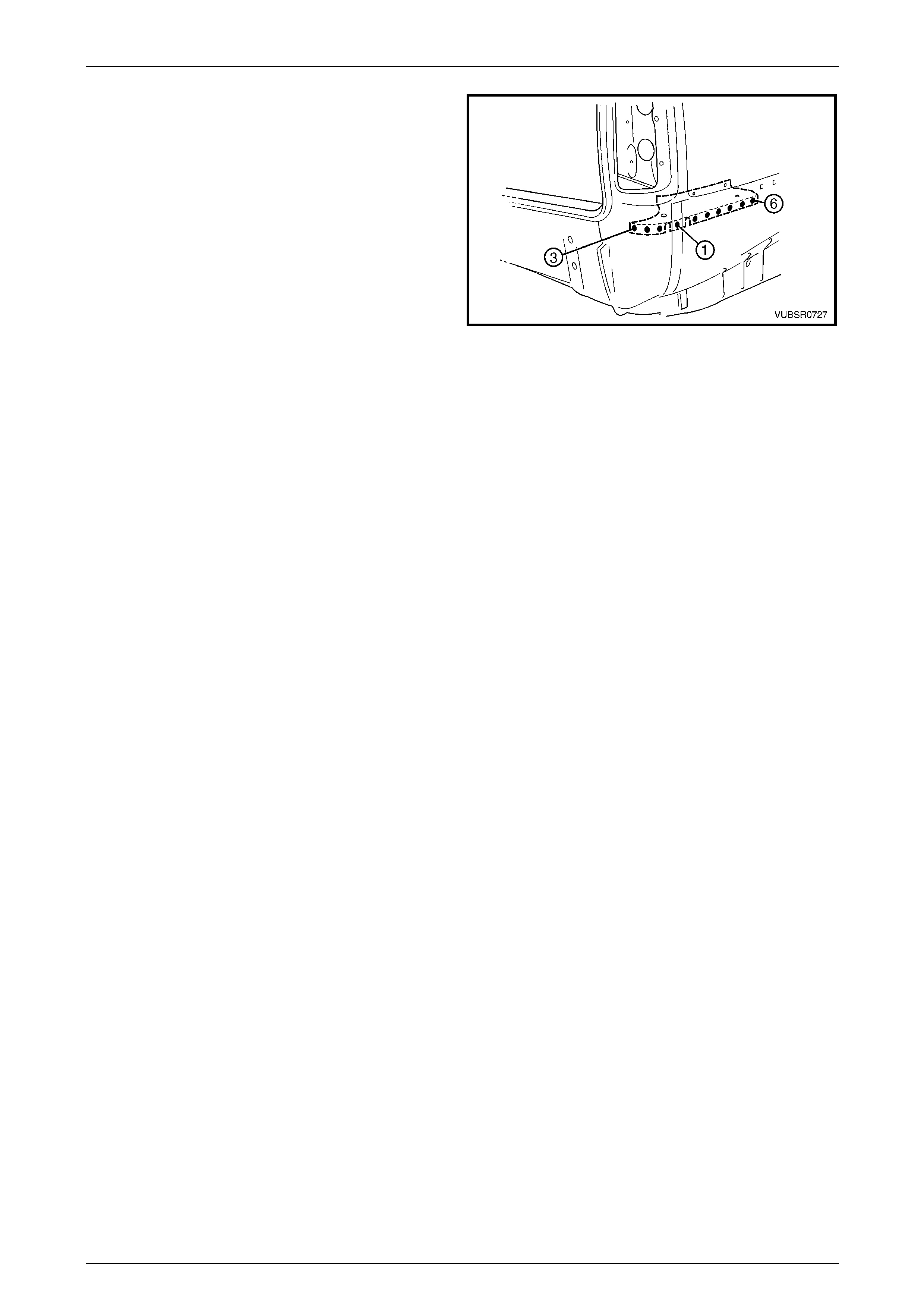
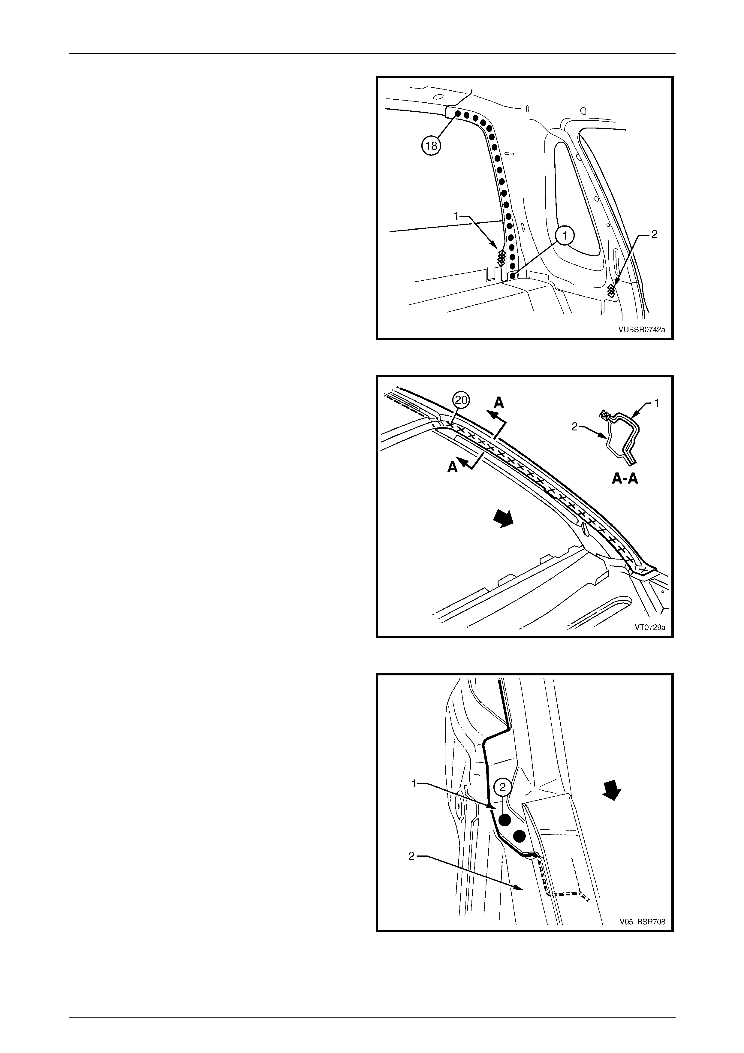
9 Spot cut the welds attaching the rear quarter panel to
the door opening frame assembly.
10 Spot cut the welds attaching the rear quarter panel to
the side inner upper panel assembly and lock pillar
outer panel brace, refer to Figure 7C – 9.
11 Remove the rear quarter panel and repair any damage
to adjacent parts as required.
NOTE
Acrylic spot weld sealer is used in many of the
joints which may require prisi ng apart.
12 Check and rectify the alignme nt of
the body as requir ed,
refer to Section 3C Body Construction – Utility.
Figure 7C – 8
Figure 7C – 9
7C Body Side – Utility Page 7C-8
Page 7C-8
Replace
NOTE
• Spot welding is the preferred method for
attaching of panels and should be used
whenever possible. Where the spot welding
equipment available will not access the
required weld position, a plug weld should be
performed.
• The same number and position of spot welds
(or plug welds) should be used when
replacing the panel, as was used during
manufacture, in order to maintain the original
structural strength of the vehicle.
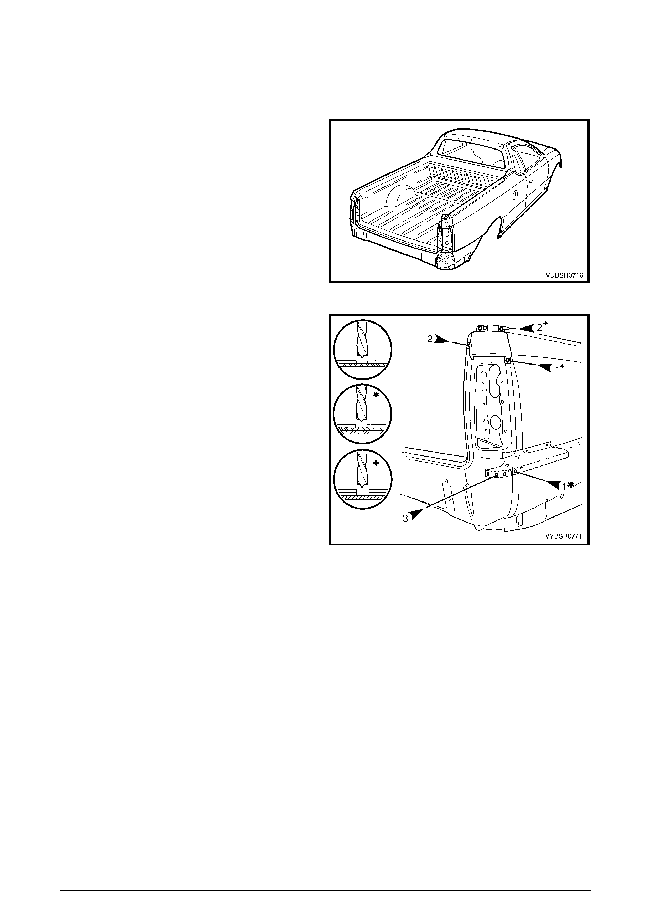
1 As required, mark the new panel with drilling locations in preparation for plug welding. Drill holes as required.
2 Prepare all mating surfaces and treat with Weld Through Primer (Item 1) as requir ed,
refer to Section 3C Body Construction – Utility
3 For the right-hand side, if required spot or plug weld
the fuel filler pipe housing to the rear q uarter panel in
four places.
4 Apply Acrylic Spot Weld Sealer (Item 2),
refer to Section 3C Body Construction – Utility.
5 Clamp the panel into position ensuring correct
alignment with the door and the body structure.
6 Spot or plug weld the rear quarter panel to the side
inner upper panel and lock pil lar outer p anel brace,
refer to Figure 7C – 11.
Figure 7C – 10
Figure 7C – 11
7C Body Side – Utility Page 7C-9
Page 7C-9
7 Spot or plug weld the rear quarter panel to the door
opening frame assembly.
Figure 7C – 12
8 Spot or plug weld the rear quarter panel to the door
opening frame assembly.
Figure 7C – 13
9 Spot or plug weld the rear quarter panel to the door
opening frame assembly and quarter panel inner
assembly around the wheel arch opening.
10 Spot or plug weld the rear quarter panel as shown in
Figure 7C – 15. Note differences between the left-
hand and right-hand sides.
Figure 7C – 14
7C Body Side – Utility Page 7C-10
Page 7C-10
Figure 7C – 15
11 Spot or plug weld the rear quarter panel to the quarter
outer lower rear panel, seven plac es.
12 Install and spot or plug weld the quarter panel upper
extension:
• to the quarter panel extension, two places,
• to the quarter panel extension and side inner
upper panel, two places,
• to the rear quarter panel and quarter panel
extension, one place.
13 Refinish and paint panels and other components as
required. Refer to Section 3 Body Construction .
14 Apply Joint Sealer (Item 3) as required.
Refer to Section 3C Body Construction – Utility.
15 Apply Cavity Wax (Item 8) as required to the inside of
any box sections or areas inaccessible to paint,
refer to Section 3C Body Construction – Utility.
16 Apply Spray-on Dea dener (Item 7) where applicab le,
refer to Section 3C Body Construction – Utility.
17 Replace the rear and quarter wind ows, refer to
Section 1A6 Stationary Windows in the MY2005 VZ
Service Information.
18 Install the remaining components as described in the
appropriate Section of the MY2005 VZ Service
Information.
Figure 7C – 16
7C Body Side – Utility Page 7C-11
Page 7C-11
2.2 Quarter Panel Extension – Replace
Remove
1 Remove the adjacent bolt-on panels a nd components
as described in the appropriate Section of the MY2005
VZ Service Information.
Figure 7C – 17
2 To access the spot welds underneath, the quarter
panel upper extension piece will require removal. Spot
cut:
• two welds attaching it and the quarter panel
extension to the side inner upper panel,
• one weld attaching it and the rear qu arter panel
to the quarter panel extension,
• two welds attaching it to the quarter panel
extension.
3 Spot cut the three welds attaching the quarter panel
extension to the quarter outer lower rear panel.
4 Spot cut the weld attaching the rear quarter panel and
quarter panel extension to the quarter outer lower rear
panel.
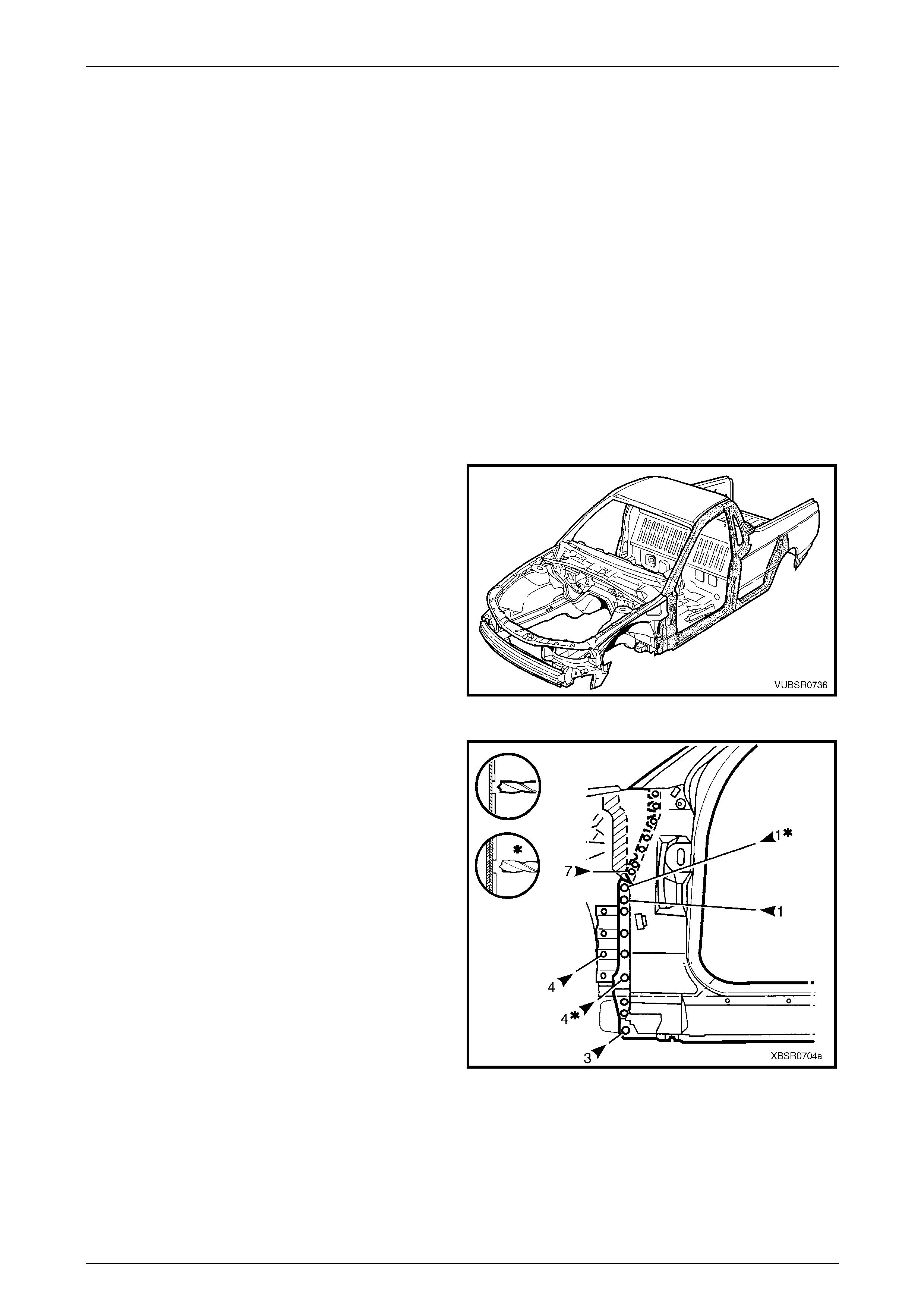
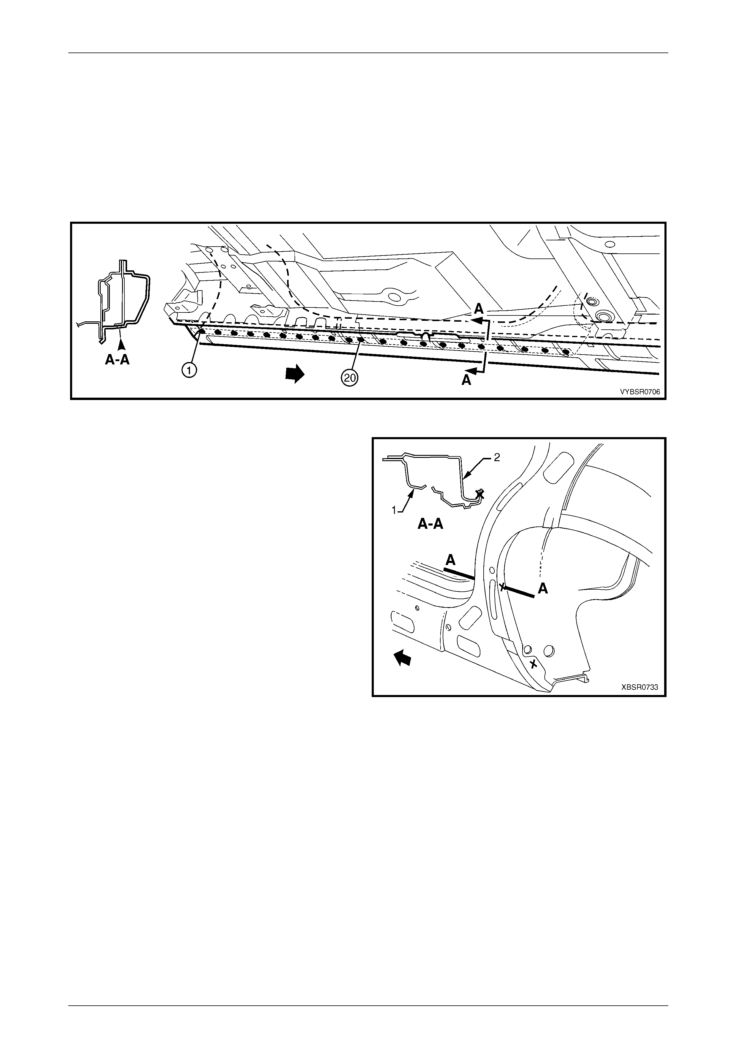
Figure 7C – 18
7C Body Side – Utility Page 7C-12
Page 7C-12
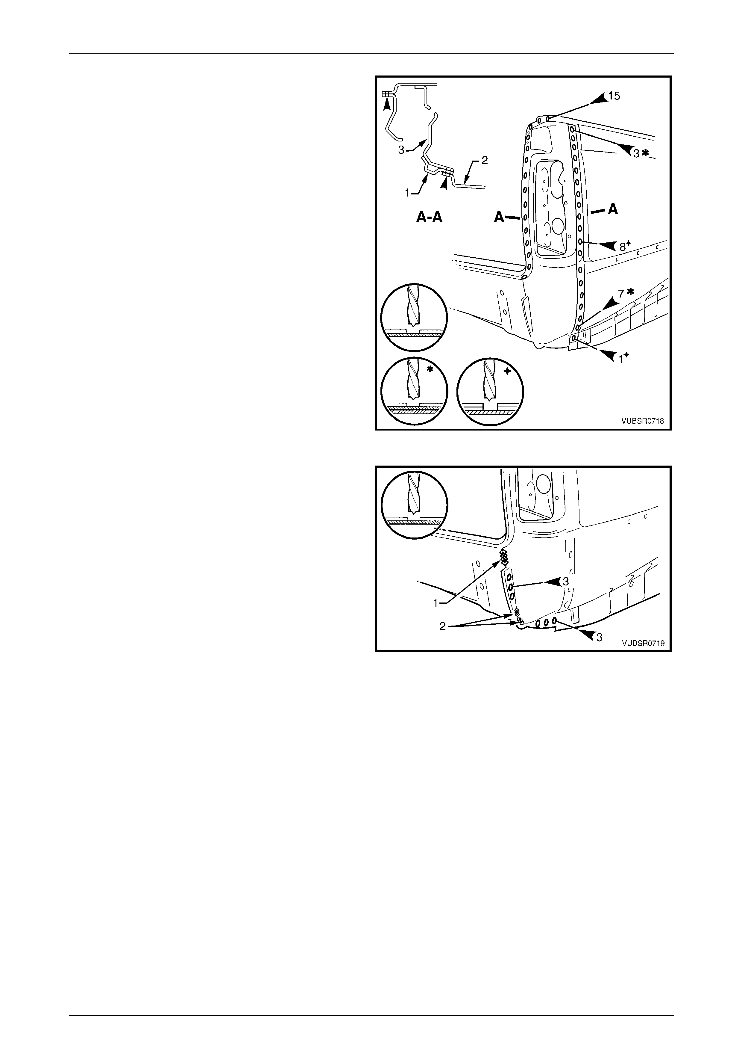
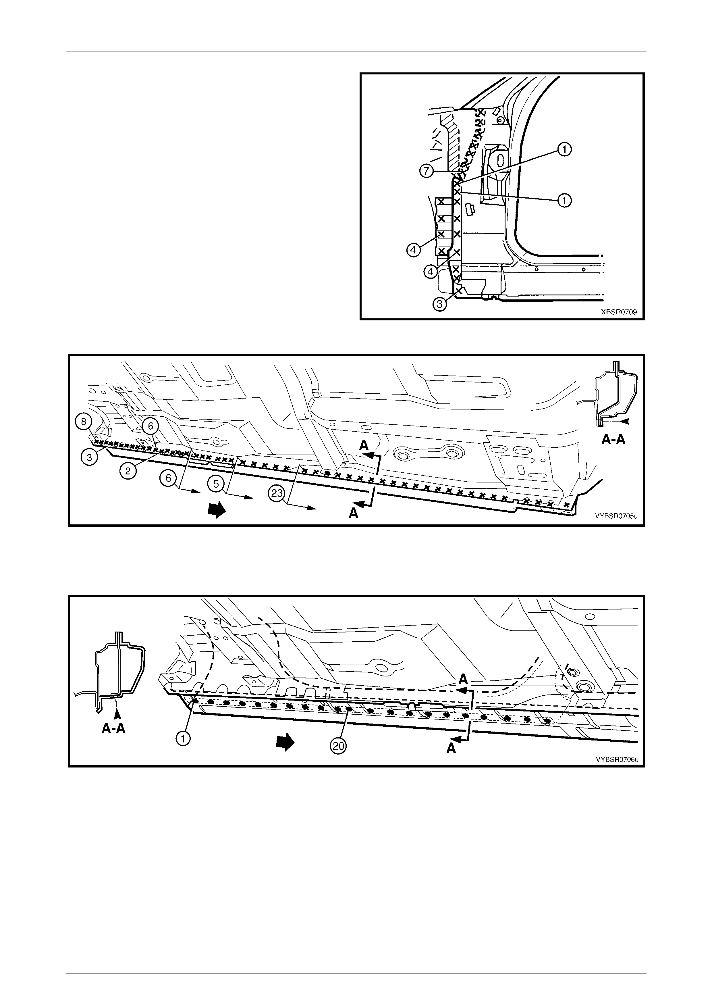
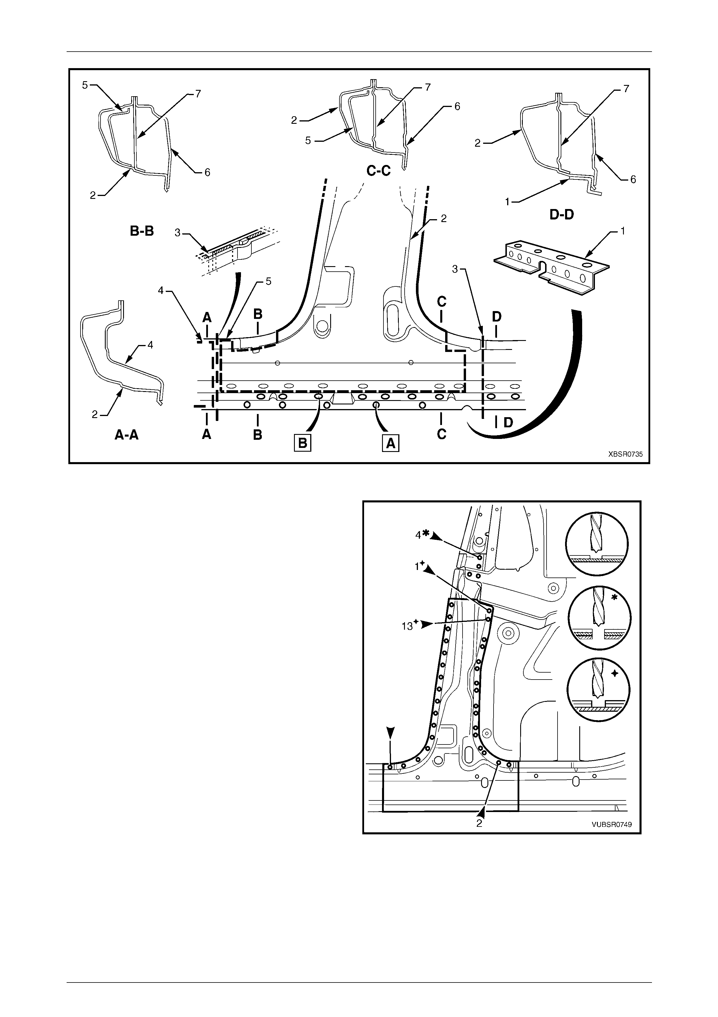
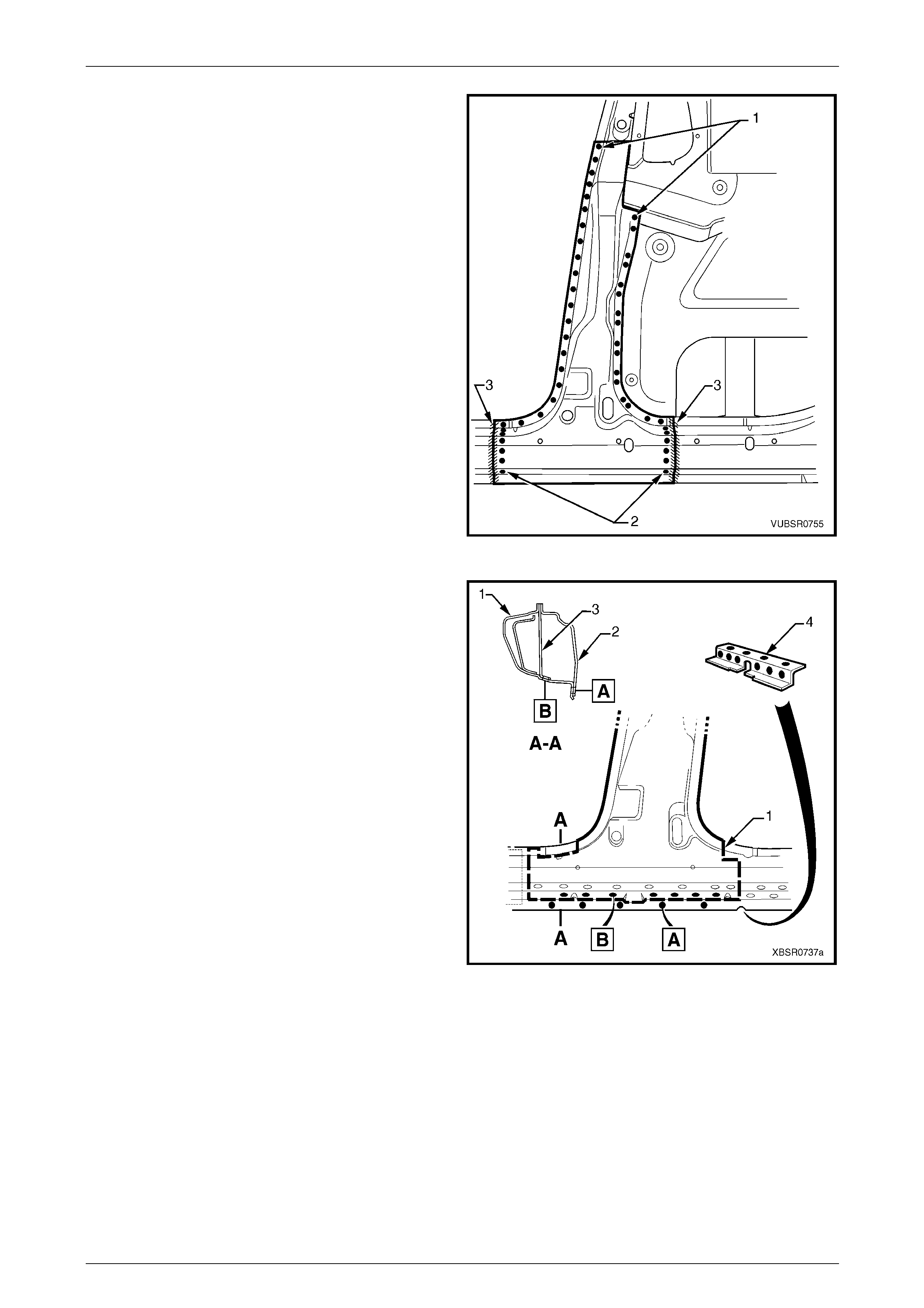
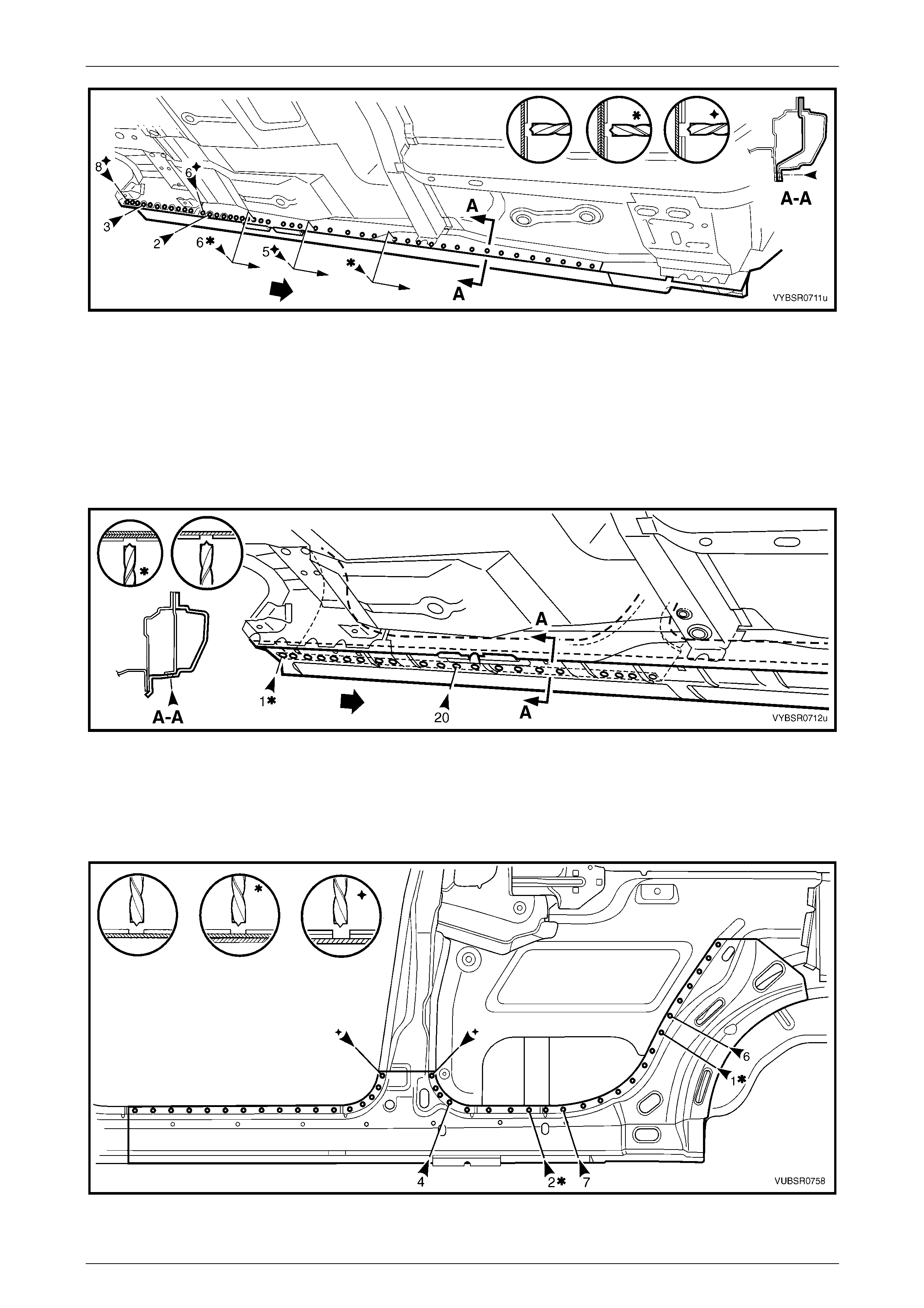
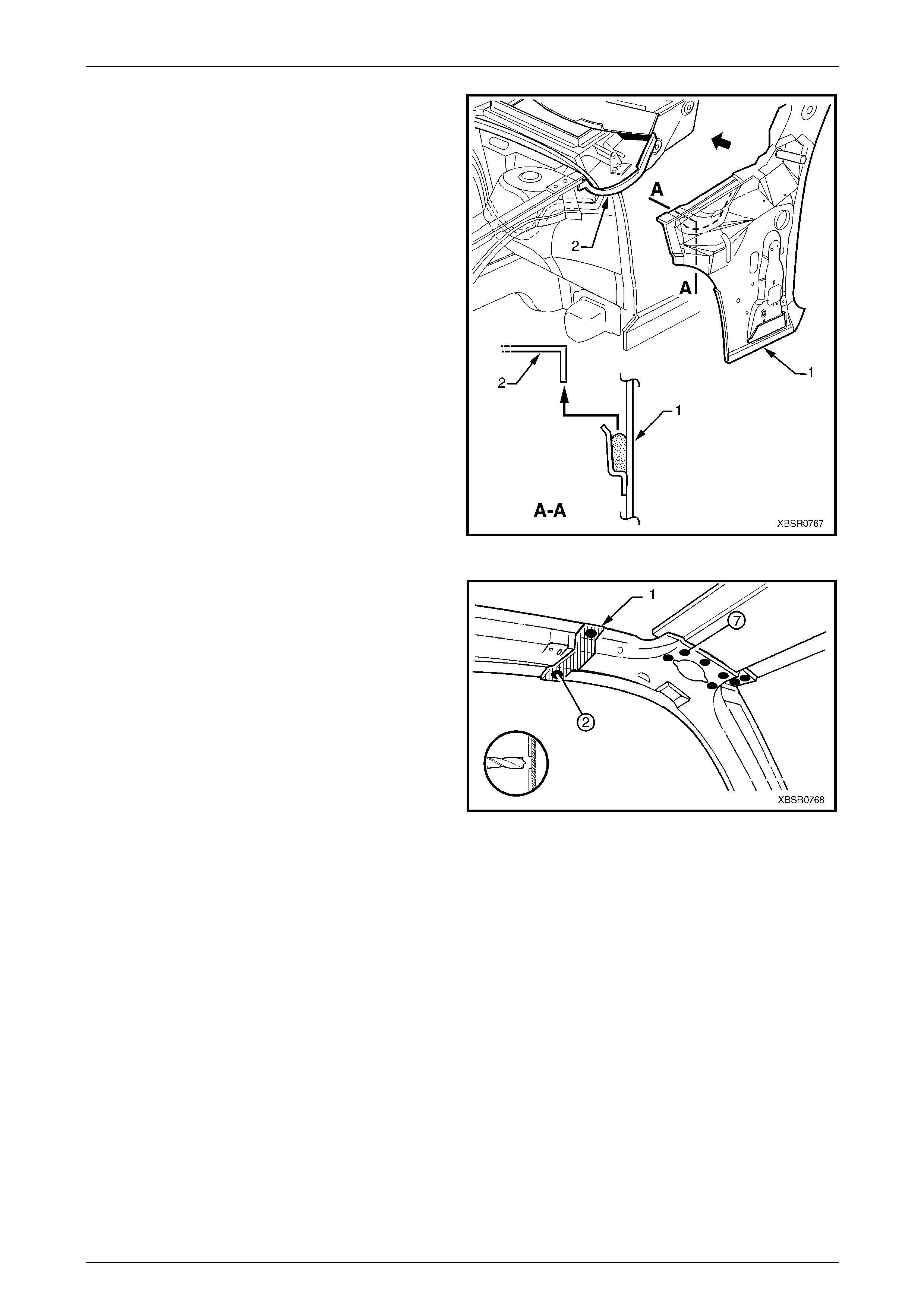
5 Spot cut the 8 welds attaching the quarter panel
extension (1) between the rear quarter panel (2) and
quarter inner lower rear extension (3),
refer to Section A-A.
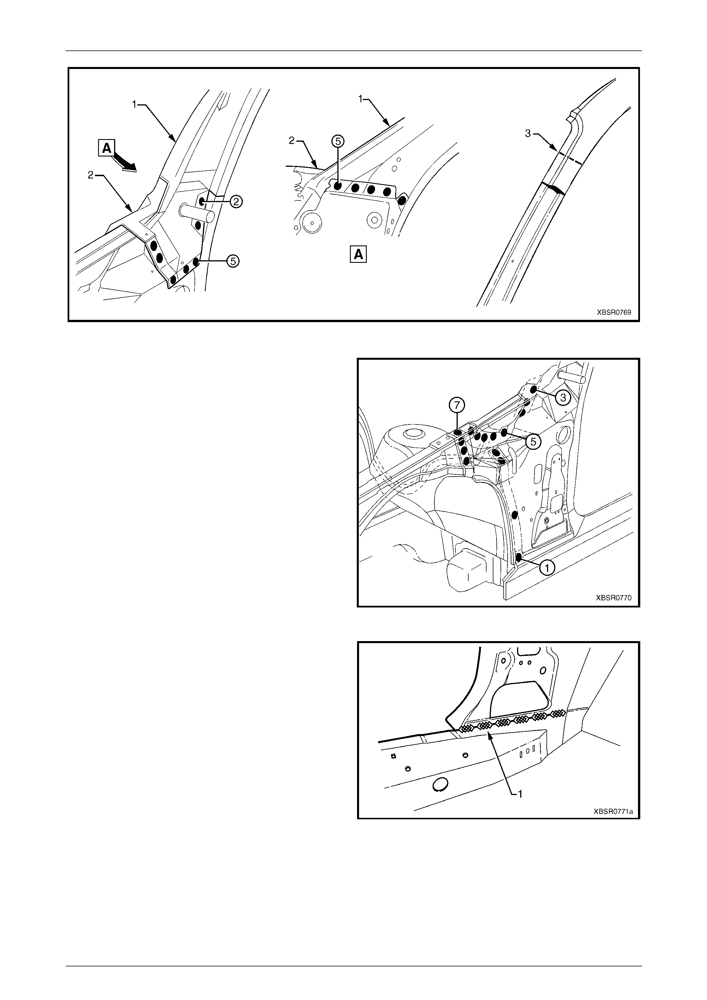
6 Spot cut the 10 welds attaching the quarter pane l
extension to the rear quarter panel.
7 Spot cut the weld attaching the rear quarter panel and
quarter panel extension to the side inner upp er pan el.
8 Spot cut the 15 welds attaching the quarter pane l
extension to the side inner upper panel.
Figure 7C – 19
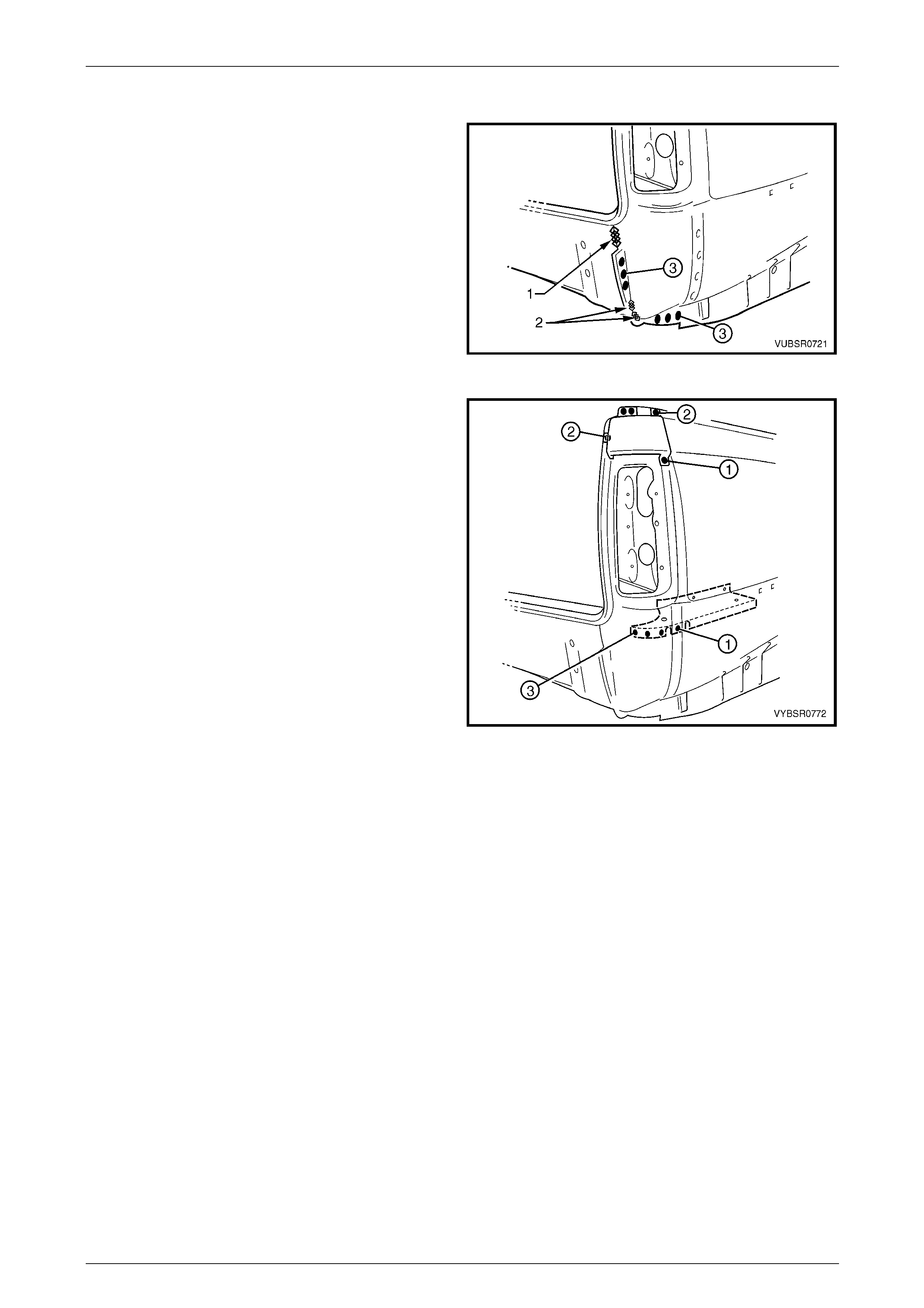
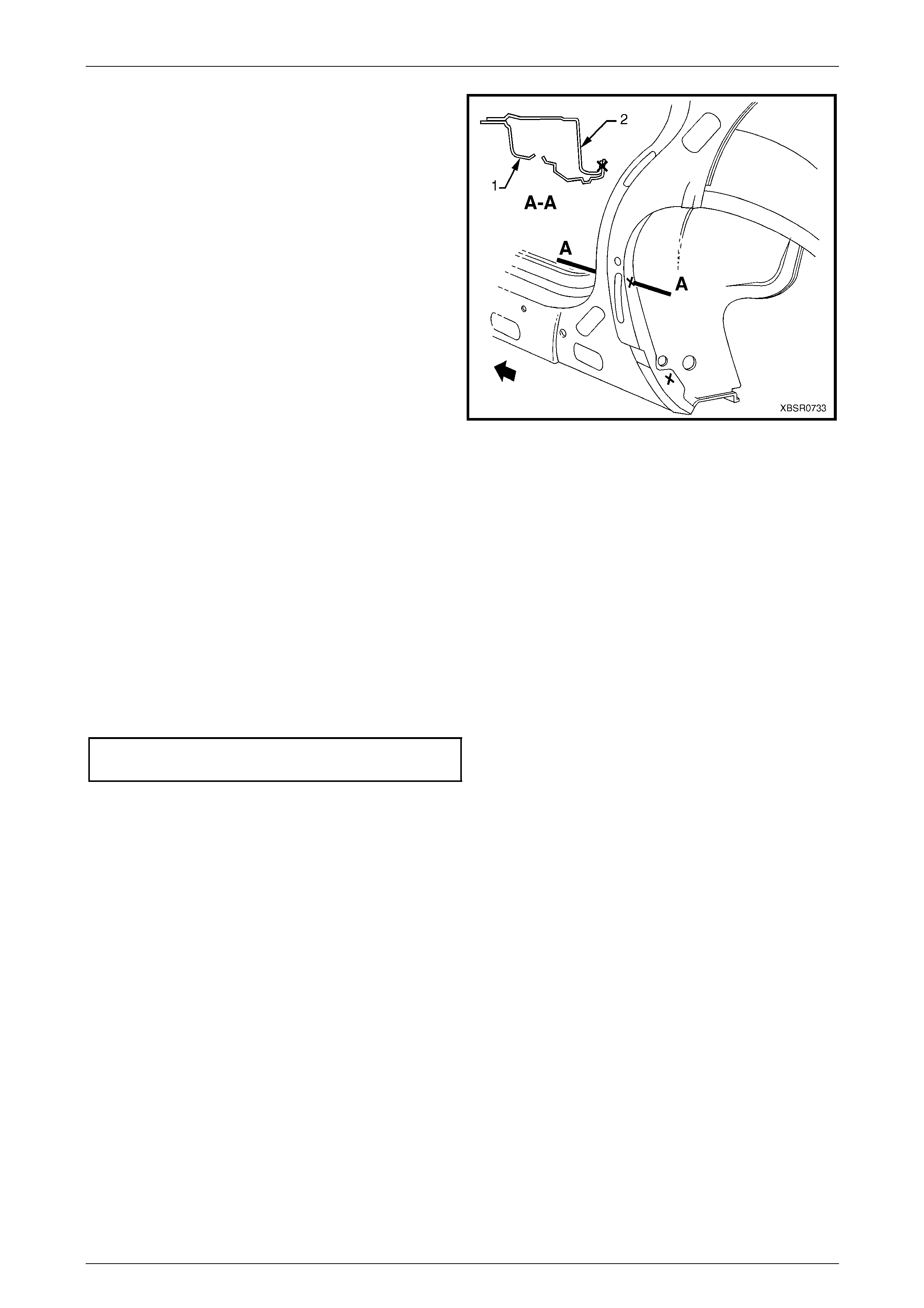
9 Spot cut the 3 welds attaching the quarter panel
extension to the side inner upper panel.
10 Spot cut the 3 welds attaching the quarter panel
extension to the rear end lower panel.
11 Grind off the MIG weld (1) and two MIG welds (2)
attaching the quarter panel extension to the rear end
lower panel.
12 Remove the quarter panel extension and repair an y
damage to adjacent parts as required.
NOTE
Acrylic spot weld sealer is used between the rear
quarter panel and quarter panel extension which
may require prising apart.
13 Check and rectify the alignme nt of
the body as requir ed,
refer to Section 3C Body Construction – Utility
Figure 7C – 20
7C Body Side – Utility Page 7C-13
Page 7C-13
Replace
NOTE
• Spot welding is the preferred method for
attaching of panels and should be used
whenever possible. Where the spot welding
equipment available will not access the
required weld position, a plug weld should be
performed.
• The same number and position of spot welds
(or plug welds) should be used when
replacing the panel, as was used during
manufacture, in order to maintain the original
structural strength of the vehicle.
1 As required, mark the new panel with drilling locations in preparation for plug welding. Drill holes as required.
2 Prepare all mating surfaces and treat with Weld Through Primer (Item 1) as requir ed,
refer to Section 3C Body Construction – Utility.
3 Apply Acrylic Spot Weld Sealer (Item 2), refer to Section 3C Body Construction – Utility.
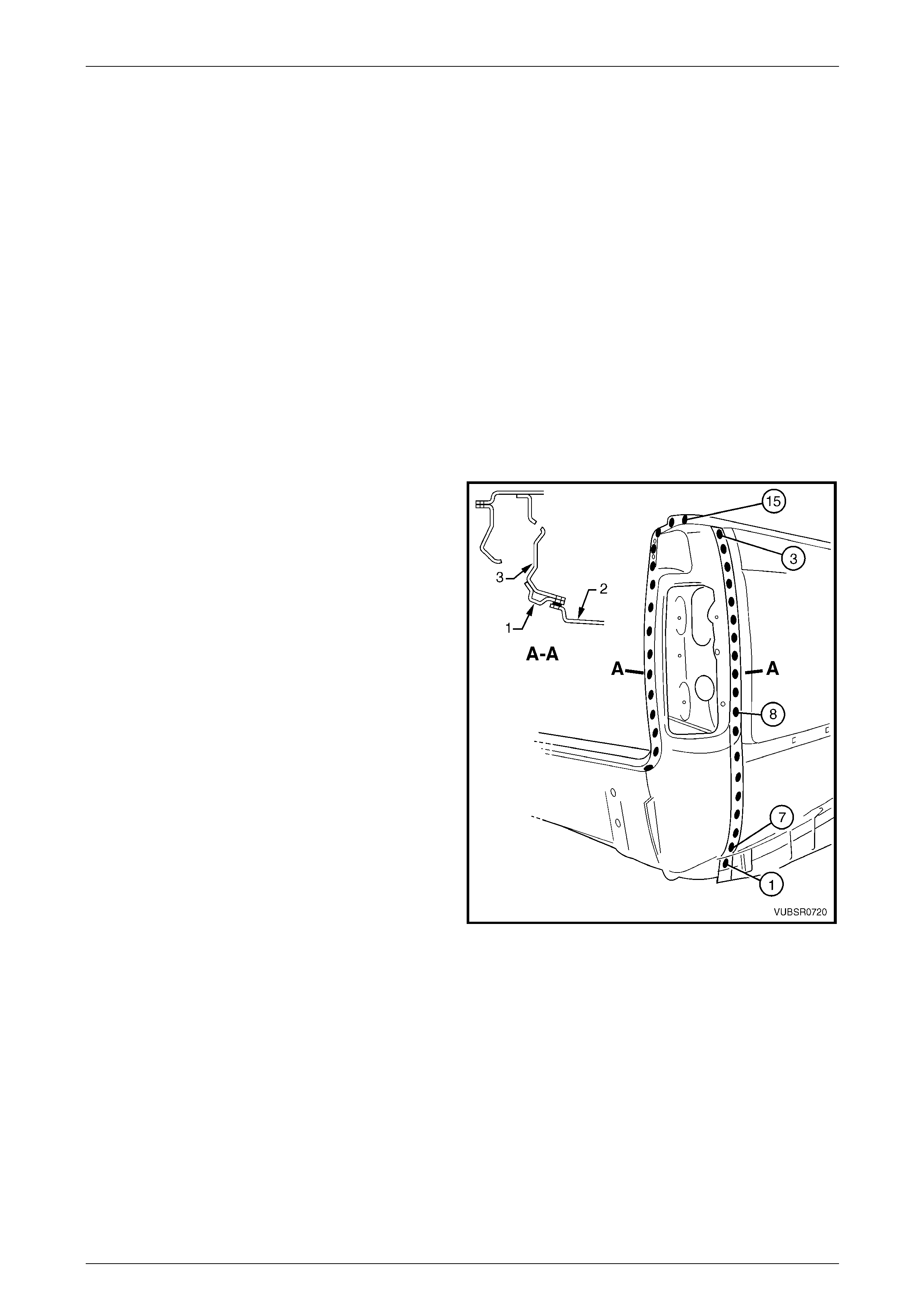
4 Clamp the panel into position, fitting the quarter panel
extension flange (1) between the rear quarter panel (2)
and quarter inner lower rear extension (3), refer to
Section A-A.
5 Test fit the tail lamp and check for correct alignment
with the endgate and the body structure.
6 Spot or plug weld eight places, the quarter panel
extension (1), rear quarter panel (2) and quarter inner
lower rear extension (3), refer to Section A-A.
NOTE
Take care when welding the rear quarter panel
to avoid heat distortion.
7 Spot or plug weld 10 places, the rear quarter panel to
the quarter panel extension.
8 Spot or plug weld one place, the rear quarter panel
and quarter panel extension to the side inner upper
panel.
9 Spot or plug weld the quarter panel e xtensio n to the
side inner upper panel, 15 pl aces.
Figure 7C – 21
7C Body Side – Utility Page 7C-14
Page 7C-14
10 Spot or plug weld three places, the quarter p anel
extension to the side inner upper panel.
11 Spot or plug weld three places, the quarter p anel
extension to the rear end lower panel.
12 MIG weld one place 55 mm (1) and two places 30 mm
(2), the quarter panel extension to the rear end lower
panel.
Figure 7C – 22
13 Spot or plug weld three places, the quarter p anel
extension to the quarter outer lower rear panel.
14 Spot or plug weld one place, the rear quarter panel
and quarter panel extension to the qu arter outer lower
rear panel.
15 Install and spot or plug weld the quarter panel upper
extension:
• and the quarter panel e xtens ion to the side inner
upper panel two plac es,
• and the rear quarter panel to the quarter panel
extension one place,
• to the quarter panel extension two places.
16 Refinish and paint panels and other components as
required. Refer to Section 3 Body Construction .
17 Apply Joint Sealer (Item 3) as required.
Refer to Section 3C Body Construction – Utility.
18 Apply Cavity Wax (Item 8) as required to the inside of
any box sections or areas inaccessible to paint,
refer to Section 3C Body Construction – Utility.
19 Install the remaining components as described in the
appropriate Section of the MY2005 VZ Service
Information.
Figure 7C – 23
7C Body Side – Utility Page 7C-15
Page 7C-15
2.3 Quarter Panel Inner Lower Rear
Extension – Replace
Remove
1 Remove the adjacent bolt-on panels a nd components
as described in the appropriate Section of the MY2005
VZ Service Information.
2 Remove the quarter panel extension as previously
described.
Figure 7C – 24
3 Spot cut the welds attaching the quarter inner lower
rear extension to the side inner upper panel.
4 Remove the quarter inner lo wer rear extension and
repair any damage to adjacent parts as required.
Figure 7C – 25
7C Body Side – Utility Page 7C-16
Page 7C-16
Replace
NOTE
• Spot welding is the preferred method for
attaching of panels and should be used
whenever possible. Where the spot welding
equipment available will not access the
required weld position, a plug weld should be
performed.
• The same number and position of spot welds
(or plug welds) should be used when
replacing the panel, as was used during
manufacture, in order to maintain the original
structural strength of the vehicle.
1 As required, mark the new panel with drilling locations in preparation for plug welding. Drill holes as required.
2 Prepare all mating surfaces and treat with Weld Through Primer (Item 1) as requir ed,
refer to Section 3C Body Construction – Utility.
3 Clamp in position and spot or plug weld the quarter
inner lower rear extension to the side inner upper
panel.
4 Replace the quarter panel extension as previously
described.
5 Replace any other remov ed panels as required.
6 Refinish and paint panels and other components as
required. Refer to Section 3 Body Construction .
7 Apply Joint Sealer (Item 3) as required.
Refer to Section 3C Body Construction – Utility.
8 Apply Cavity Wax (Item 8) as required to the inside of
any box sections or areas inaccessible to paint,
refer to Section 3C Body Construction – Utility.
9 Install the remaining components as described in the
MY2005 VZ Service Information.
Figure 7C – 26
7C Body Side – Utility Page 7C-17
Page 7C-17
2.4 Quarter Outer Lower Rear Panel –
Replace
Remove
1 Remove the adjacent bolt-on panels a nd components
as described in the appropriate Section of the MY2005
VZ Service Information.
2 Remove the adjacent panels as required, refer to the
appropriate procedure in this Section.
Figure 7C – 27
3 Spot cut the welds attaching the rear quarter panel
and quarter panel extension to the qu arter outer lower
rear panel.
Figure 7C – 28
7C Body Side – Utility Page 7C-18
Page 7C-18
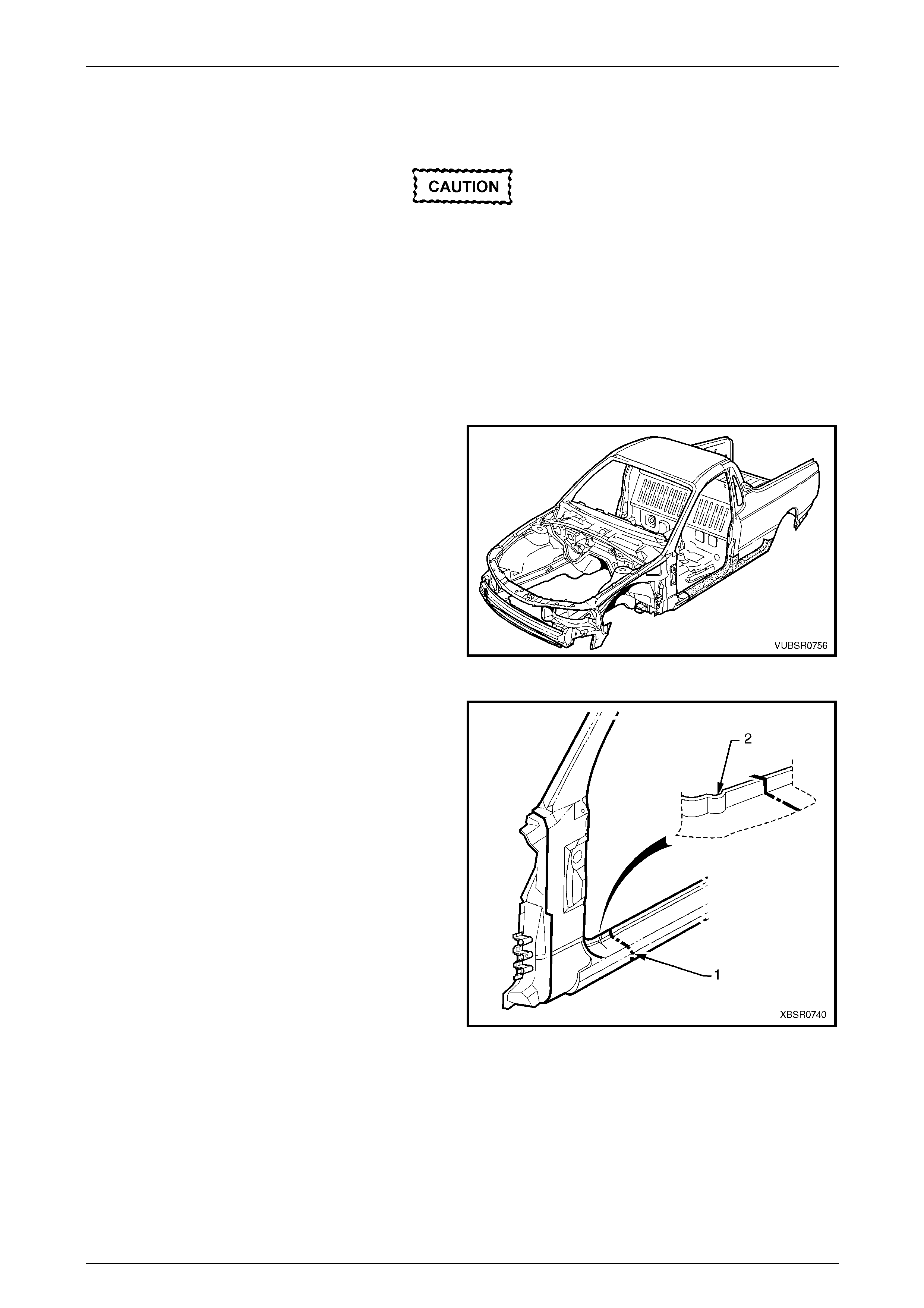
4 Spot cut the welds attaching the quarter outer lo wer
rear panel (1) to the side inner upper panel (2) and
load floor panel (3), refer to View A-A.
NOTE
If the rear quarter panel was removed, cut these
welds from the outer side.
5 Spot cut the two welds attaching the quarter outer
lower rear panel (1) to the side inner upper pane l (2),
refer to View B-B.
NOTE
These two welds are hidden behind the load
floor flange. If the rear quarter panel has been
removed cut them from the outer side. If it wasn’t
removed, locate the spots through the inner
panel opening and drill through the flange and
side inner upper panel.
6 Remove the quarter outer lower rear pa nel from the
vehicle, then repair any damage to adjacent parts as
required.
Figure 7C – 29
Replace
NOTE
• Spot welding is the preferred method for
attaching of panels and should be used
whenever possible. Where the spot welding
equipment available will not access the
required weld position, a plug weld should be
performed.
• The same number and position of spot welds
(or plug welds) should be used when
replacing the panel, as was used during
manufacture, in order to maintain the original
structural strength of the vehicle.
1 As required, mark the new panel with drilling locations in preparation for plug welding. Drill holes as required.
2 Prepare all mating surfaces and treat with Weld Through Primer (Item 1) as requir ed,
refer to Section 3C Body Construction – Utility.
3 Spot or plug weld the quarter outer lower rear panel to
the side inner upper panel and load floor flange.
Figure 7C – 30
7C Body Side – Utility Page 7C-19
Page 7C-19
4 Spot or plug weld the quarter outer lower rear panel to
the rear quarter panel and quarter panel extension.
5 Replace any removed panels as required, refer to the
appropriate procedure in this Section.
6 Refinish and paint panels and other components as
required. Refer to Section 3 Body Construction .
7 Apply Joint Sealer (Item 3) as required.
Refer to Section 3C Body Construction – Utility.
8 Apply Cavity Wax (Item 8) as required to the inside of
any box sections or areas inaccessible to paint,
refer to Section 3C Body Construction – Utility.
9 Install the remaining components as described in the
MY2005 VZ Service Information. Figure 7C – 31
7C Body Side – Utility Page 7C-20
Page 7C-20
2.5 Quarter Lower Rear Panel – Replace
1 Remove the adjacent bolt-on panels a nd components
as described in the appropriate Section of the MY2005
VZ Service Information.
2 Remove the adjacent panels as required, refer to the
appropriate procedure in this Section.
Figure 7C – 32
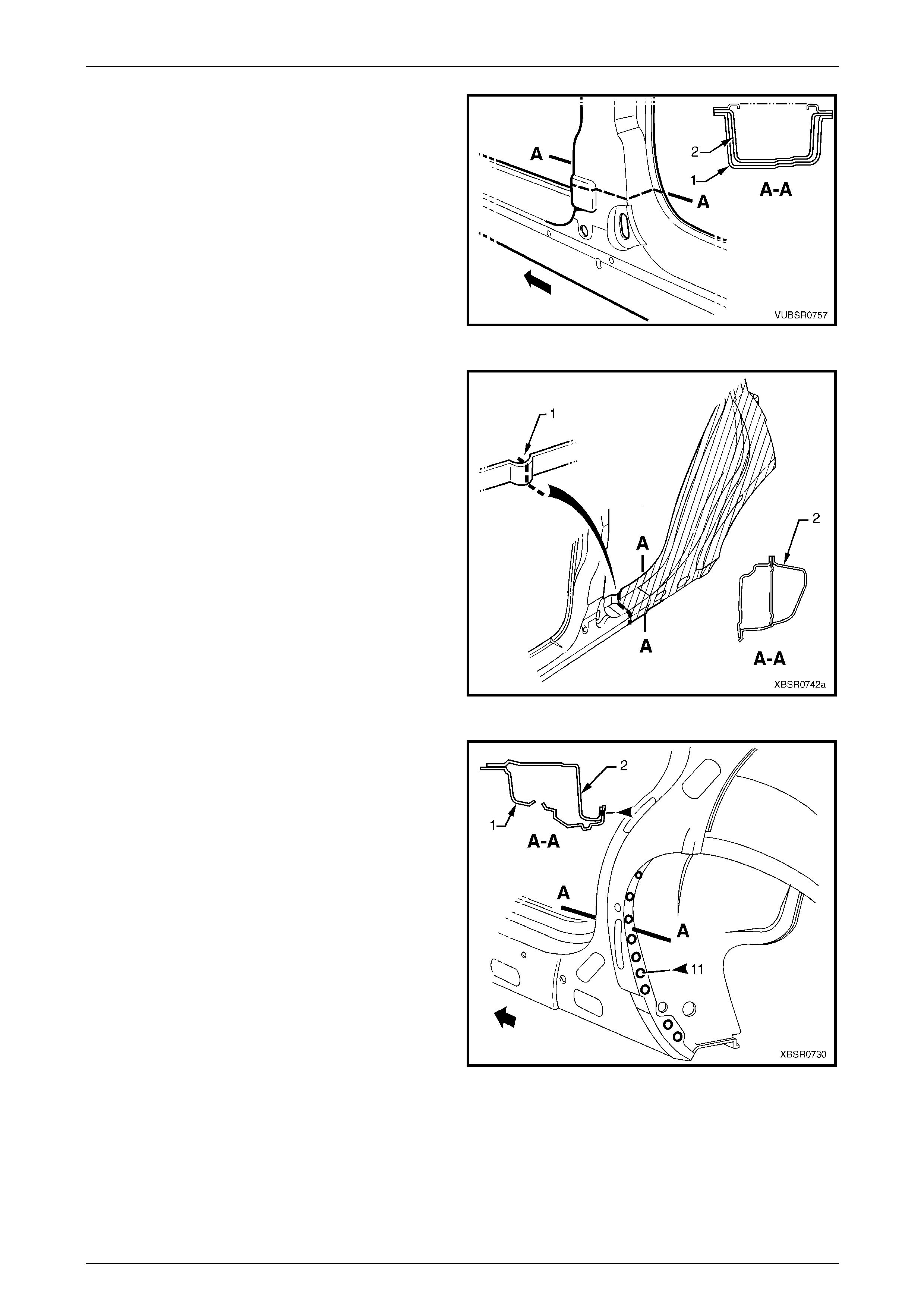
3 Spot cut the welds attaching the quarter lower rear
panel to the:
• side inner upper panel, three places,
• quarter panel extension, three places,
• rear end lower panel, one place,
• rear end panel, three plac es.
4 Carefully grind the MIG weld along the quarter lower
rear panel and rear end lower panel join.
Figure 7C – 33
5 If the quarter panel extension (1) was removed, spot
cut the four welds attaching the quarter lower rear
panel to the side inner upper panel (A).
NOTE
If the quarter panel extension was not removed,
spot cut through the side inner upper panel and
load floor panel, the four welds attaching the
quarter lower rear panel to the side inner upper
panel (B).
6 Carefully grind the MIG weld (2) along the quarter
lower rear panel and side inner upp er panel join.
7 Remove the panel from the vehicle, then repair any
damage to adjacent parts as required.
Figure 7C – 34
7C Body Side – Utility Page 7C-21
Page 7C-21
Replace
NOTE
• Spot welding is the preferred method for
attaching of panels and should be used
whenever possible. Where the spot welding
equipment available will not access the
required weld position, a plug weld should be
performed.
• The same number and position of spot welds
(or plug welds) should be used when
replacing the panel, as was used during
manufacture, in order to maintain the original
structural strength of the vehicle.
1 As required, mark the new panel with drilling locations in preparation for plug welding. Drill holes as required.
2 Prepare all mating surfaces and treat with Weld Through Primer (Item 1) as requir ed,
refer to Section 3C Body Construction – Utility.
3 If the quarter panel extension (1) was removed, spot
or plug weld four places, the quarter lower rear panel
to the side inner upper panel (A).
NOTE
If the quarter panel extension was not removed,
spot or plug weld the quarter lower rear panel
through the side inner upper p anel and load floo r
panel, four places (B).
Figure 7C – 35
4 Spot or plug weld the quarter lo wer rear panel to the:
• side inner upper panel, three places,
• quarter panel extension, three places,
• rear end lower panel, one place,
• rear end panel, three plac es.
5 MIG weld along the quarter lower rear panel, side
inner upper panel and rear en d panel join.
6 Replace any other remov ed panels as required.
7 Refinish and paint panels and other components as
required. Refer to Section 3 Body Construction .
8 Apply Joint Sealer (Item 3) as required.
Refer to Section 3C Body Construction – Utility.
9 Apply Cavity Wax (Item 8) as required to the inside of
any box sections or areas inaccessible to paint,
refer to Section 3C Body Construction – Utility.
10 Install the remaining components as described in the
appropriate Section of the MY2005 VZ Service
Information.
Figure 7C – 36
7C Body Side – Utility Page 7C-22
Page 7C-22
2.6 Door Opening Frame Assembly –
Replace
Remove
NOTE
• This procedure requires the removal of the
roof panel. As an alternative, the door
opening frame assembly can be cut at the
upper pillar sections by following the
procedures in 2.7 Door Opening Frame
Assembly – Partial Replace, Hinge Pillar and
2.8 Door Opening Frame Assembly – Partial
Replace, Centre Pillar.
• Cavity Foam is used within the hinge and
centre pillar cavities. Care is required when
repairing the vehicle in these areas, refer to
Section 2 Precautions prior to beginning any
work for further information.
1 Remove the adjacent bolt-on panels a nd components
as described in the appropriate Service Information.
2 Remove the windshield and the rear window
assemblies, refer to Section 1A6 Stationary Windows
in the MY2005 VZ Service Information.
3 Remove the dash panel retaining bolt from the hinge
pillar.
4 Remove the roof panel, refer to Section 9C Roof.
5 Remove the rear quarter panel,
refer to 2.1 Rear Quarter Panel – Replace.
6 Remove the front wheelhouse pan el upper side rail,
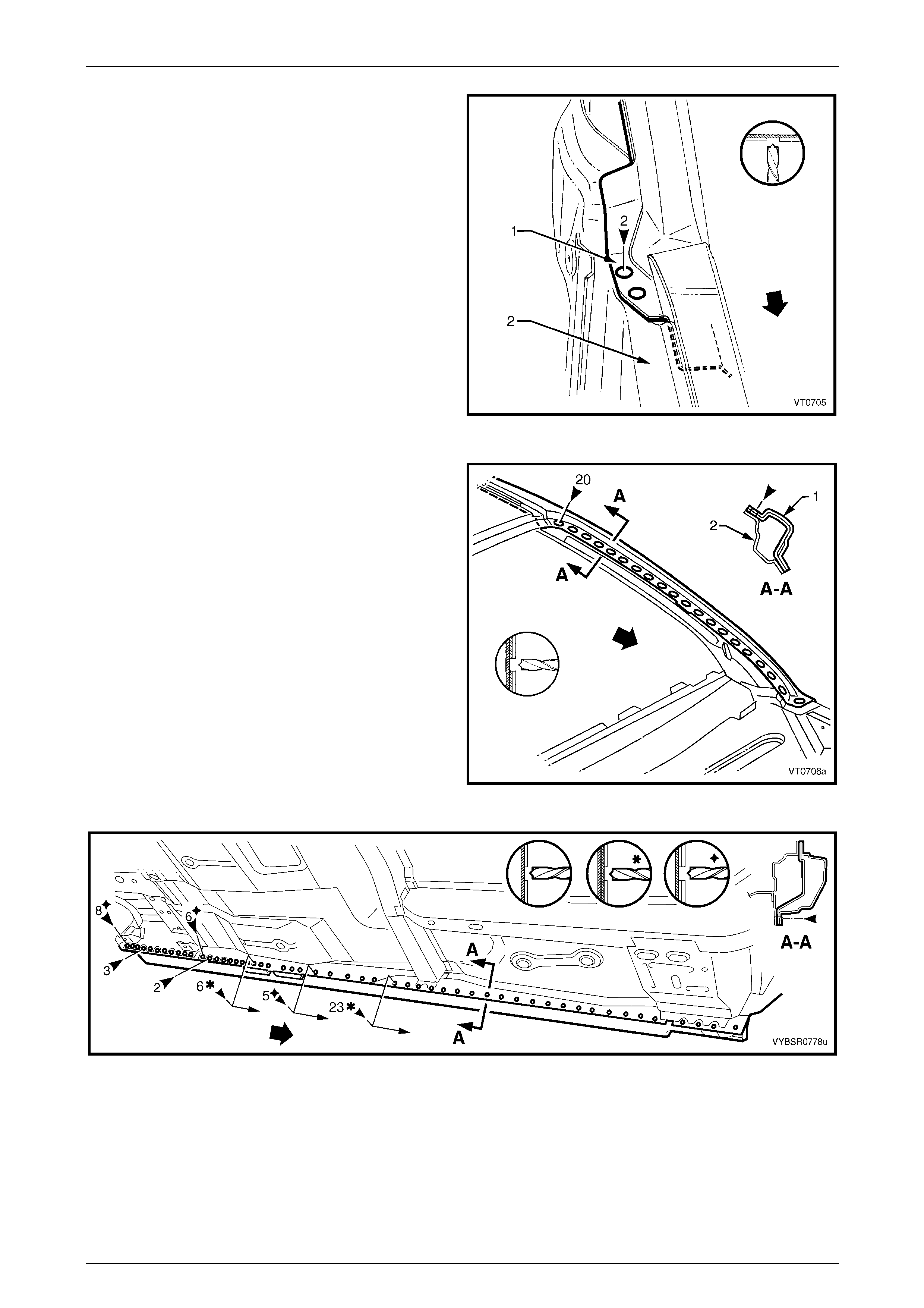
refer to Section 4 Front End. Figure 7C – 37
7 Spot cut the welds attaching the door openin g frame
assembly to the inner rocker panel and to the hin ge
pillar inner panel assembly.
NOTE
In order to spot cut the uppermost of these welds
it may be necessary to cut and peel back the
section of hinge reinforcement panel covering
the welds, to gain the required access.
Figure 7C – 38
7C Body Side – Utility Page 7C-23
Page 7C-23
8 Spot cut the two welds at the base of the hinge pillar,
attaching the door opening frame assembly (1) to the
hinge pillar inner panel assembly (2).
Figure 7C – 39
9 Spot cut the welds on the windshield side flange,
attaching the door opening frame assembly (1) to the
hinge pillar inner panel assembly (2).
10 Spot cut along the vertical flange below the rocker
panel to separate the door opening frame assembly
from the inner rocker panel, refer to Figure 7C – 41.
Figure 7C – 40
Figure 7C – 41
11 Spot cut from below, up into the rocker panel, the welds attaching the door opening frame assembly to the quarter
panel inner assembly, refer to Figure 7C – 42.
7C Body Side – Utility Page 7C-24
Page 7C-24
Figure 7C – 42
12 Spot cut the welds around the rear wheel arch, joining
the door opening frame assembly (1) to the quarter
panel inner assembly (2).
NOTE
Some welds may have been removed with the
quarter panel.
Figure 7C – 43
13 Spot cut the welds along the roof flange.
NOTE
Many of these welds may have been removed
with the roof panel.
Figure 7C – 44
7C Body Side – Utility Page 7C-25
Page 7C-25
14 Spot cut the welds attaching the door openin g frame
assembly to the side inner upper front panel.
15 Grind off the MIG weld (1) attaching the door opening
frame assembly to the front seatback panel.
16 Grind off the MIG weld (2) attaching the door opening
frame assembly to the side inner upper front panel.
Figure 7C – 45
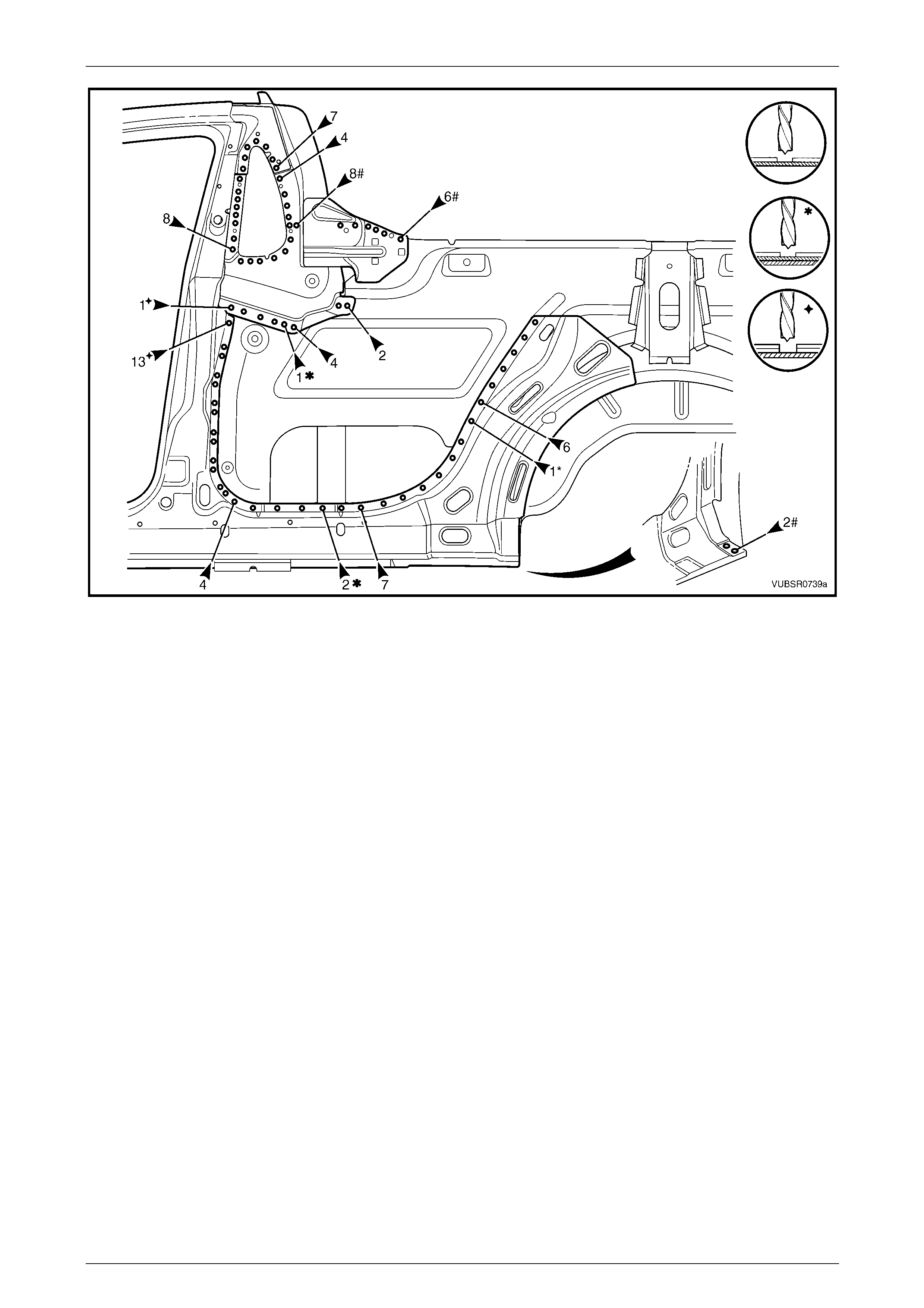
17 Spot cut the welds attaching the door openin g frame
assembly to the roof rear panel.
Figure 7C – 46
18 Spot cut the welds on the flange surrounding the front
door opening, attaching the door op ening frame
assembly to the hinge pillar inner assembly, inner
rocker panel and quarter panel in ner assembly.
19 Spot cut the welds attaching the door openin g frame
assembly to the side inner upper front panel, side
inner upper panel and quarter panel inner assembl y,
refer to Figure 7C – 48.
NOTE
Welds marked # may have been removed with
the rear quarter panel.
20 Remove the complete door opening frame assembly
and repair any dama ge to adjacent parts.
21 Check and rectify the alignme nt of
the body shell as required,
refer to Section 3C Body Construction – Utility. Figure 7C – 47
7C Body Side – Utility Page 7C-26
Page 7C-26
Figure 7C – 48
Replace
NOTE
• Spot welding is the preferred method for
attaching of panels and should be used
whenever possible. Where the spot welding
equipment available will not access the
required weld position, a plug weld should be
performed.
• The same number and position of spot welds
(or plug welds) should be used when
replacing the panel, as was used during
manufacture, in order to maintain the original
structural strength of the vehicle.
1 As required, mark the new panel with drilling locations in preparation for plug welding. Drill holes as required.
2 Prepare all mating surfaces and treat with Weld Through Primer (Item 1) as required,
refer to Section 3C Body Construction – Utility.
3 Apply Acrylic Spot Weld Sealer (Item 2), refer to Section 3C Body Construction – Utility.
7C Body Side – Utility Page 7C-27
Page 7C-27
4 Securely clamp the door openin g frame assembly in
position on the vehicle body.
5 Begin attaching the door opening frame assembly by
spot welding around the front door opening flange.
Figure 7C – 49
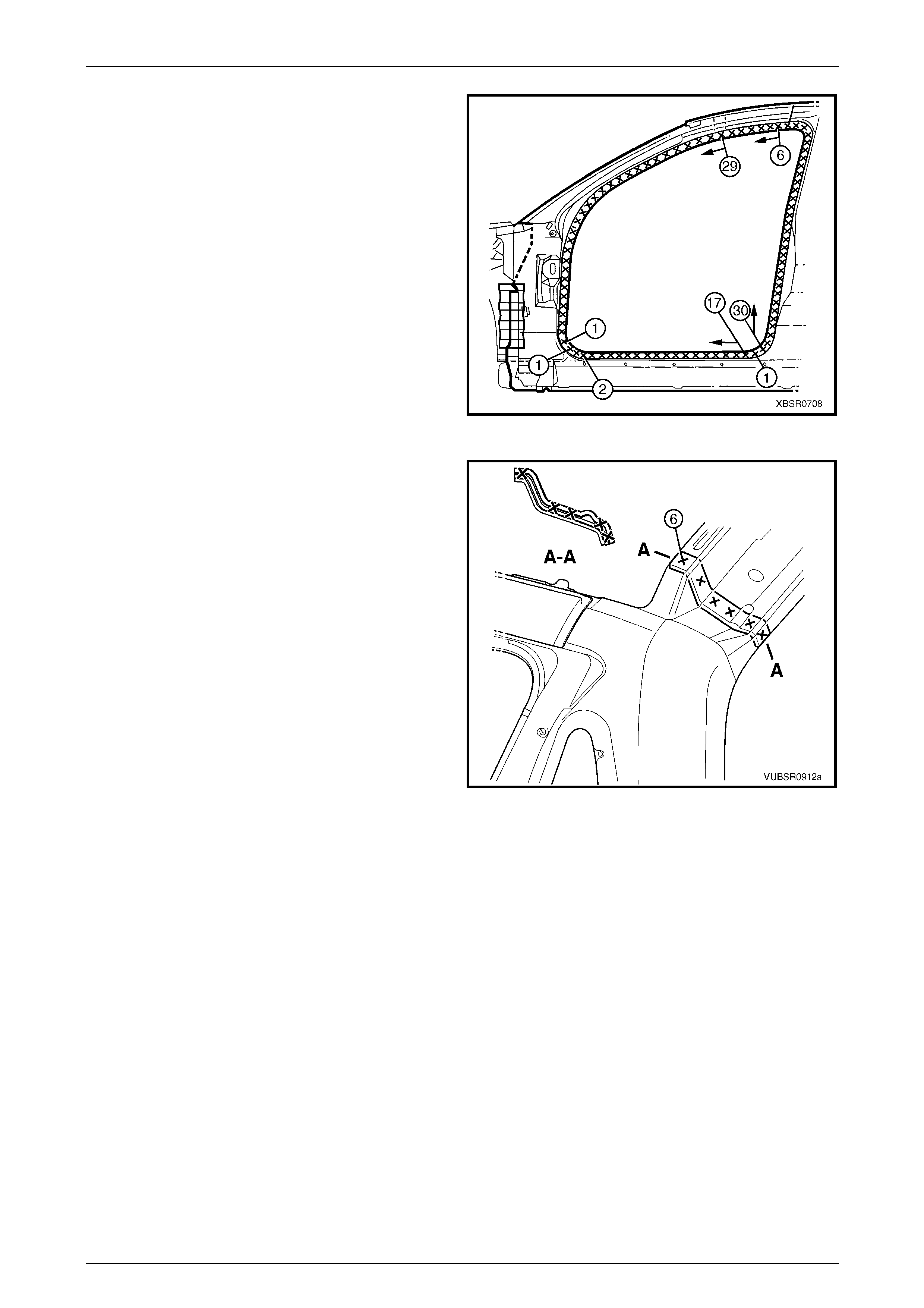
6 Spot weld the door opening frame assembly to the
roof rear panel.
7 Spot or plug weld the door opening frame assembly to
the side inner upper front panel, side inner u pper
panel and quarter pane l inner assembly,
refer to Figure 7C – 51.
Figure 7C – 50
7C Body Side – Utility Page 7C-28
Page 7C-28
Figure 7C – 51
8 Spot or plug weld the door opening frame assembly
along the roof flange.
NOTE
The remaining welds are made when the roof
panel is installed.
Figure 7C – 52
7C Body Side – Utility Page 7C-29
Page 7C-29
9 Spot or plug weld the door opening frame assembly to
the side inner upper front panel.
10 MIG weld 50 mm (1) the door opening frame assembly
to the front seatback panel.
11 MIG weld 20 mm (2) the side inner upper front panel
to the door opening frame assembly.
Figure 7C – 53
12 Spot weld along the windshield flange, attaching the
door opening frame assembly to the hinge pillar inner
panel assembly.
Figure 7C – 54
13 Spot weld in two places at the base of the hinge pillar,
attaching the door opening frame assembly (1) to the
hinge pillar inner panel assembly (2).
Figure 7C – 55
7C Body Side – Utility Page 7C-30
Page 7C-30
14 Spot or plug weld the door opening frame assembly to
the inner rocker panel and to the hinge pillar inner
panel assembly.
NOTE
If the sheet metal was modified to allow access
to these welds, it should be repaired to its
original configuration.
15 Spot weld the door opening frame assembly along the
vertical flange below the rocker panel,
refer to Figure 7C – 57.
Figure 7C – 56
Figure 7C – 57
16 Plug weld up through the rocker panel to attach the door opening frame assembly to the quarter p anel inner
assembly, refer to Figure 7C – 58.
Figure 7C – 58
7C Body Side – Utility Page 7C-31
Page 7C-31
17 Spot or plug weld in two places arou nd the rear wheel
arch, attaching the door opening frame assembly to
the quarter panel inner assembl y.
NOTE
These welds will be completed when the rear
quarter panel is replaced.
Figure 7C – 59
18 Replace front wheelhous e panel upper side rail, refer to Section 4 Front End.
19 Replace the roof panel, refer to Section 9 Roof.
20 Replace the rear quarter panel, refer to 2.1 Rear Quarter Pane l – Replace.
21 Install the door hinges, refer to Section 8 Do ors, Liftgate and Endgate.
22 Refinish and paint panels and other components as required. Refer to Section 3 Body Construction.
23 Apply Joint Sealer (Item 3) as required. Refer to Section 3C Body Construction – Utility.
24 Apply Cavity Wax (Item 8) as required to the inside of any box secti ons or areas inaccessible to paint,
refer to Section 3C Body Construction – Utility.
25 Apply Spray-on Dea dener (Item 7) where applicab le, refer to Section 3C Body Construc tion – Utility.
26 Install the dash panel retaining bolt throu gh the hinge pil lar and tighten to the specified torque.
Dash panel retaining b olt
torque specification.................................35.0 – 45.0 Nm
27 Replace the windshield and the rear window assembly, refer to Section 1A 6 Stationary Windows in the MY2005 VZ
Service Information.
28 Insert Cavity Foam into the hinge and centre pillars as required, refer to Section 2 Precautions.
29 Install the remaining components as described in the appr opriate Section of the MY2005 VZ Service Information.
7C Body Side – Utility Page 7C-32
Page 7C-32
2.7 Door Opening Frame Assembly – Partial
Replace, Hinge Pillar
Remove
NOTE
Cavity Foam is used within the hinge and
centre pillar cavities. Care is required when
repairing the vehicle in these areas, refer to
Section 2 Precautions prior to beginning work for
further information.
1 Remove the adjacent bolt-on panels a nd components
as described in the appropriate Section of the MY2005
VZ Service Information.
2 Secure an appropriate tool between the front door
opening flanges to maintain correct bod y alignment.
3 Remove the windshield, refer to
Section 1A6 Stationary Windows in the MY2005 VZ
Service Information.
4 Remove the dash panel retaining bolt from the hinge
pillar.
5 Remove the front wheelhouse pan el upper side rail,
refer to Section 4 Front End. Figure 7C – 60
6 Spot cut the welds attaching the door openin g frame
assembly to the inner rocker panel and to the hin ge
pillar inner panel assembly.
NOTE
In order to spot cut the uppermost of these welds
it may be necessary to cut and peel back the
section of hinge reinforcement panel covering
the welds, to gain the required access.
Figure 7C – 61
7C Body Side – Utility Page 7C-33
Page 7C-33
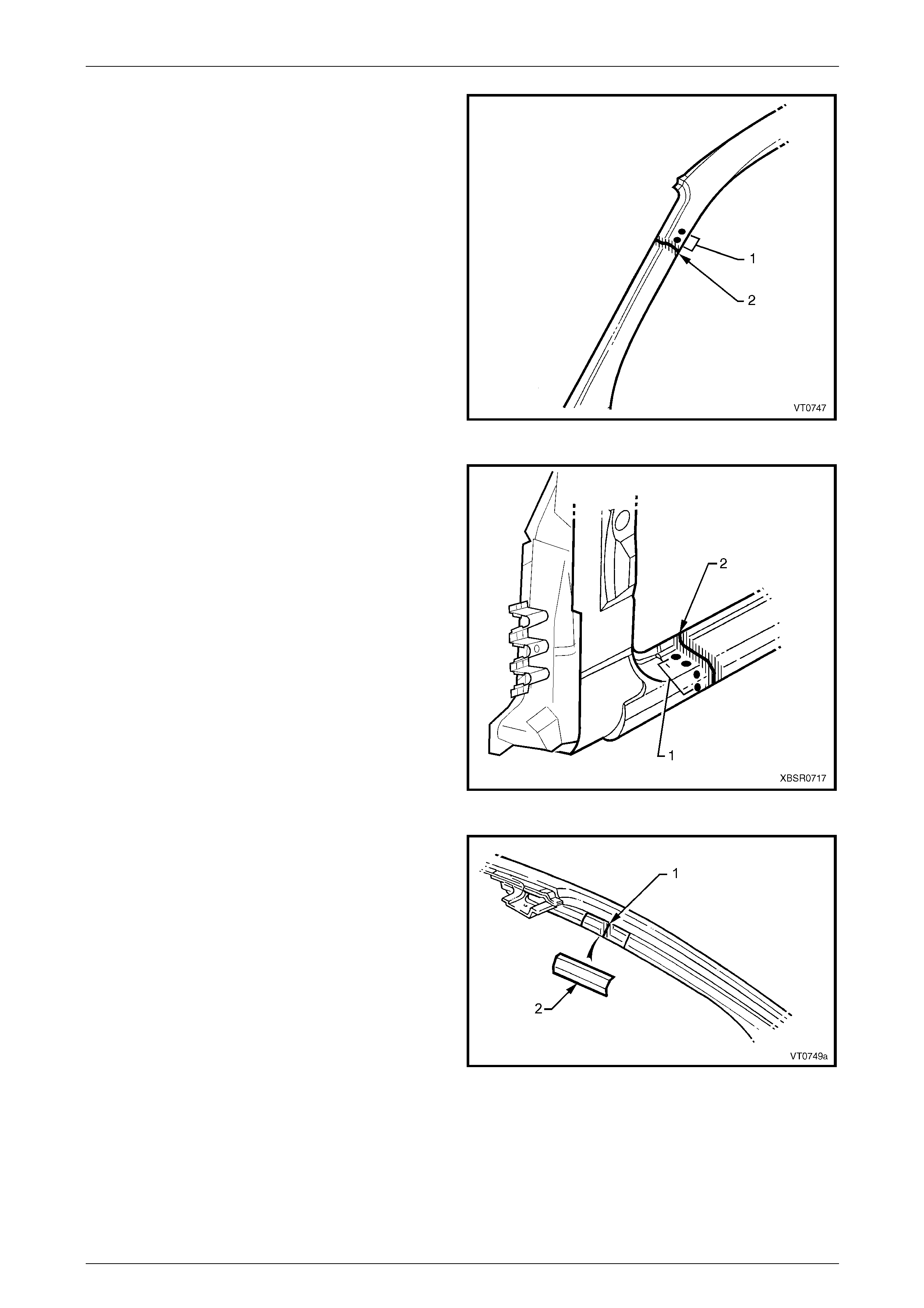
7 Spot cut the two welds at the base of the hinge pillar,
attaching the door opening frame assembly (1) to the
hinge pillar inner panel assembly (2).
Figure 7C – 62
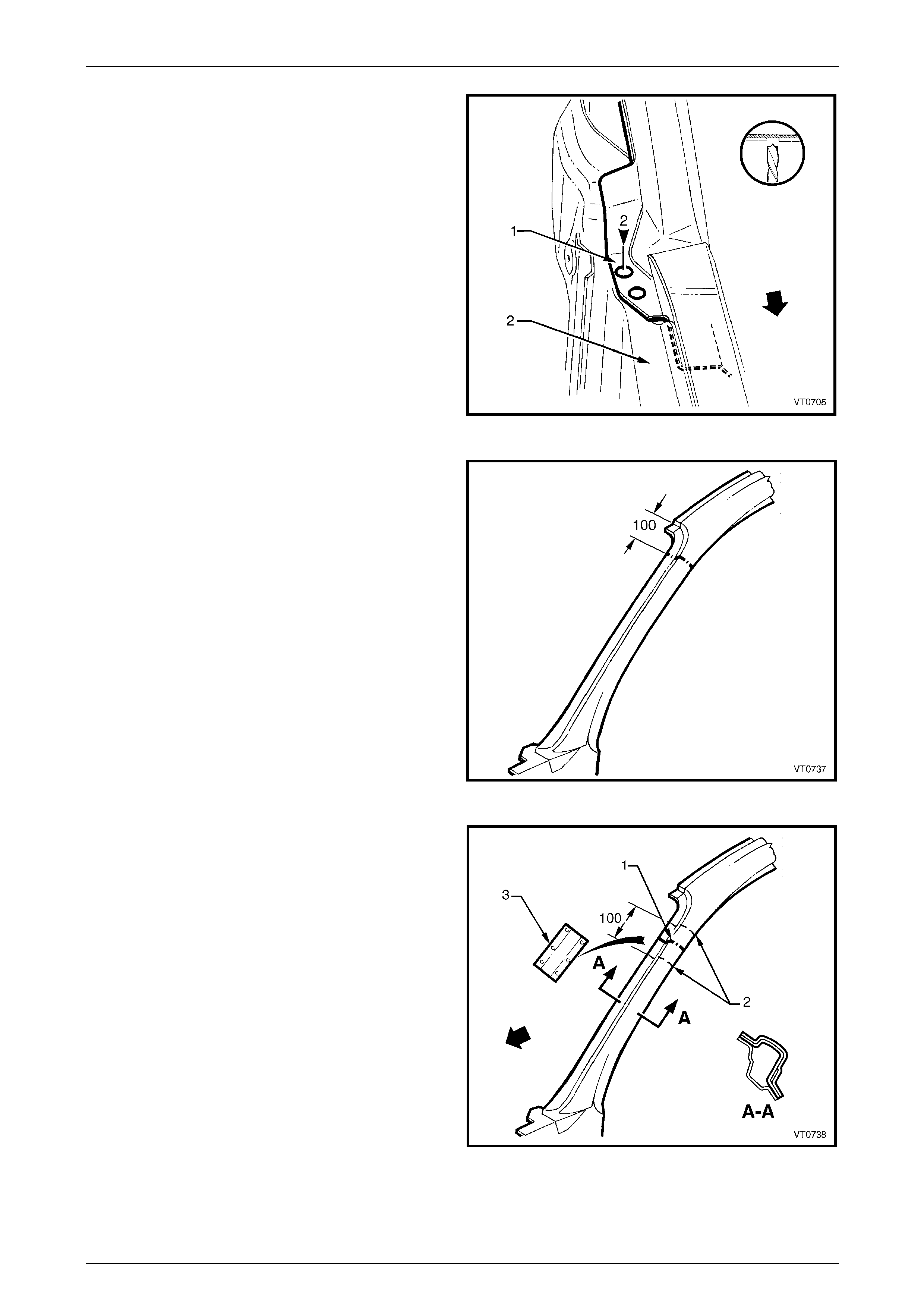
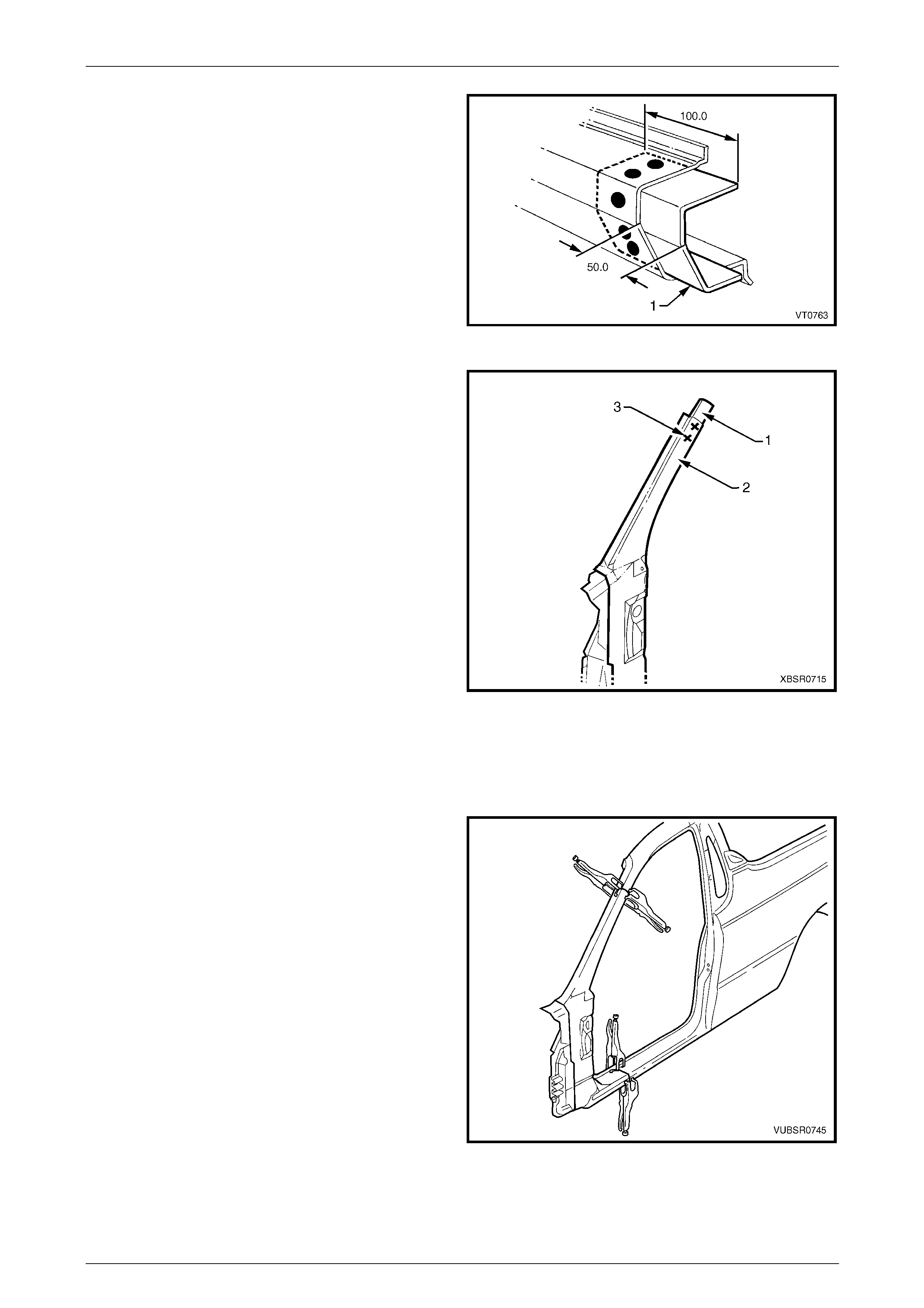
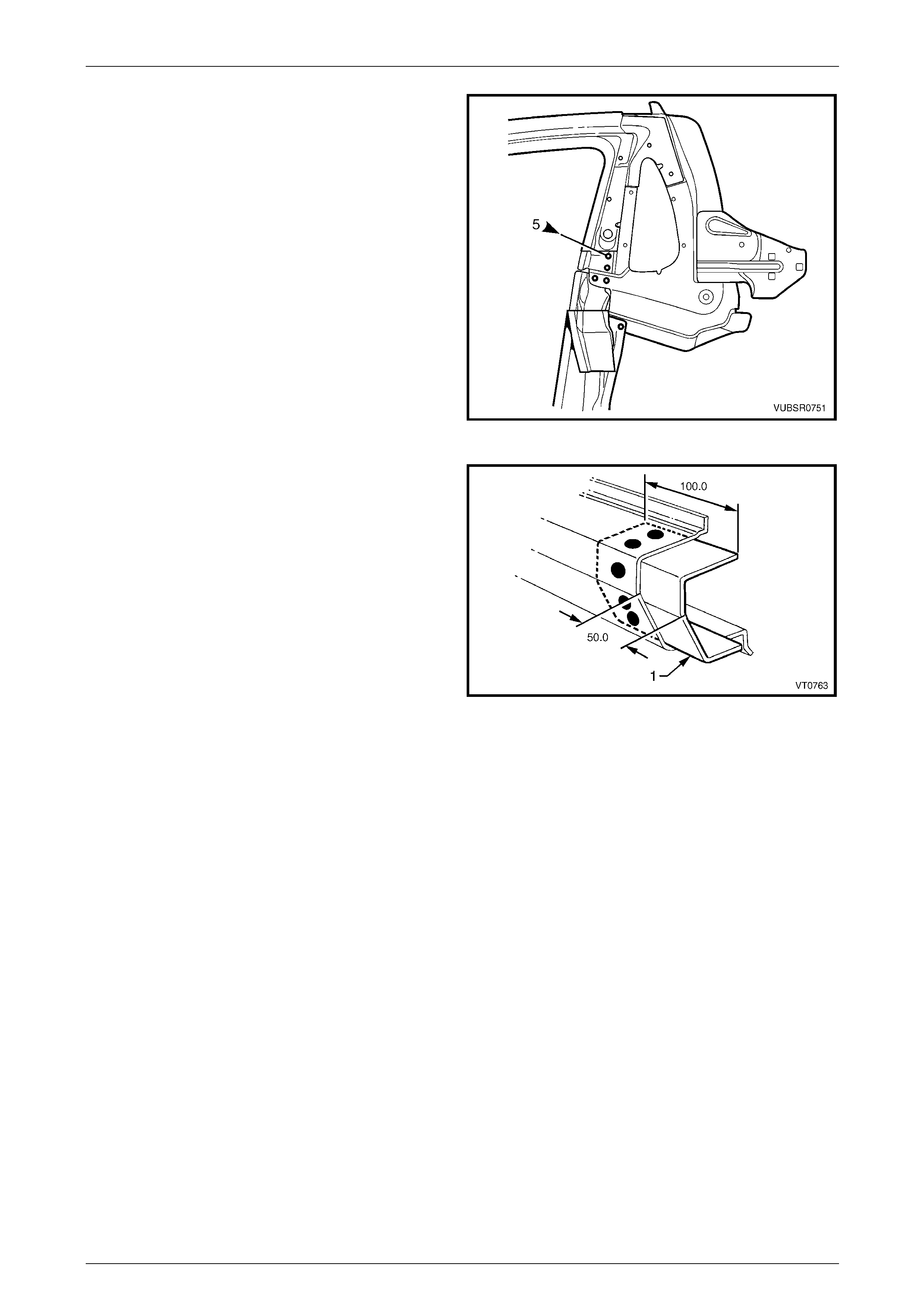
8 Select a cutting point on the hinge pillar. This cut point
should be within the region specified.
Figure 7C – 63
9 At the selected point (1), cut through the outer and
reinforcement panels, leaving the inner panel intact.
10 Mark the inner panel at points 50 mm either side of the
cut line on the outer panel and cut the inner panel at
these two points (2). Spot cut the welds and remove
the 100 mm section of inner panel (3).
Figure 7C – 64
7C Body Side – Utility Page 7C-34
Page 7C-34
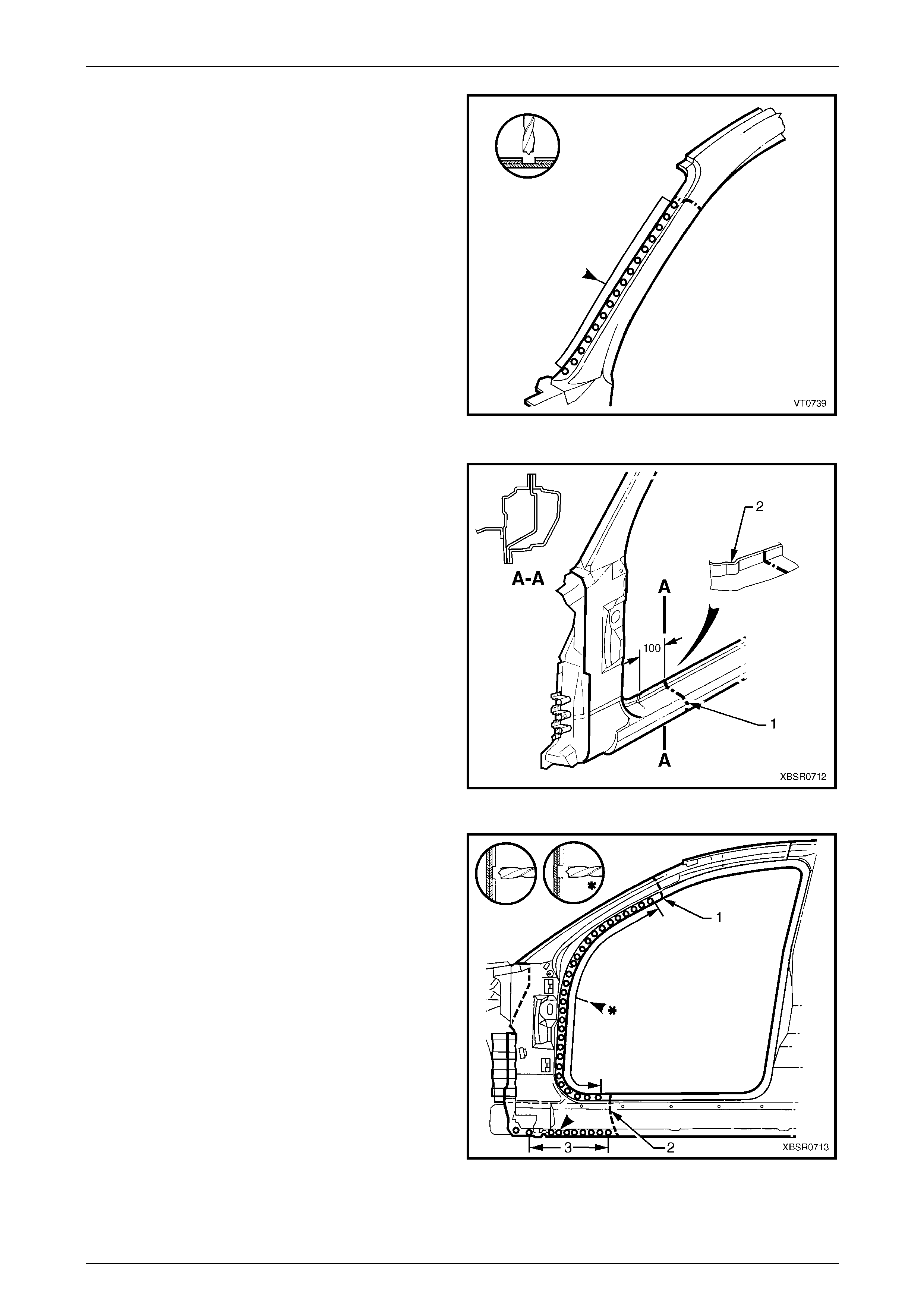
11 Spot cut the welds on the windshield side flange, up to
the point of the cut.
Figure 7C – 65
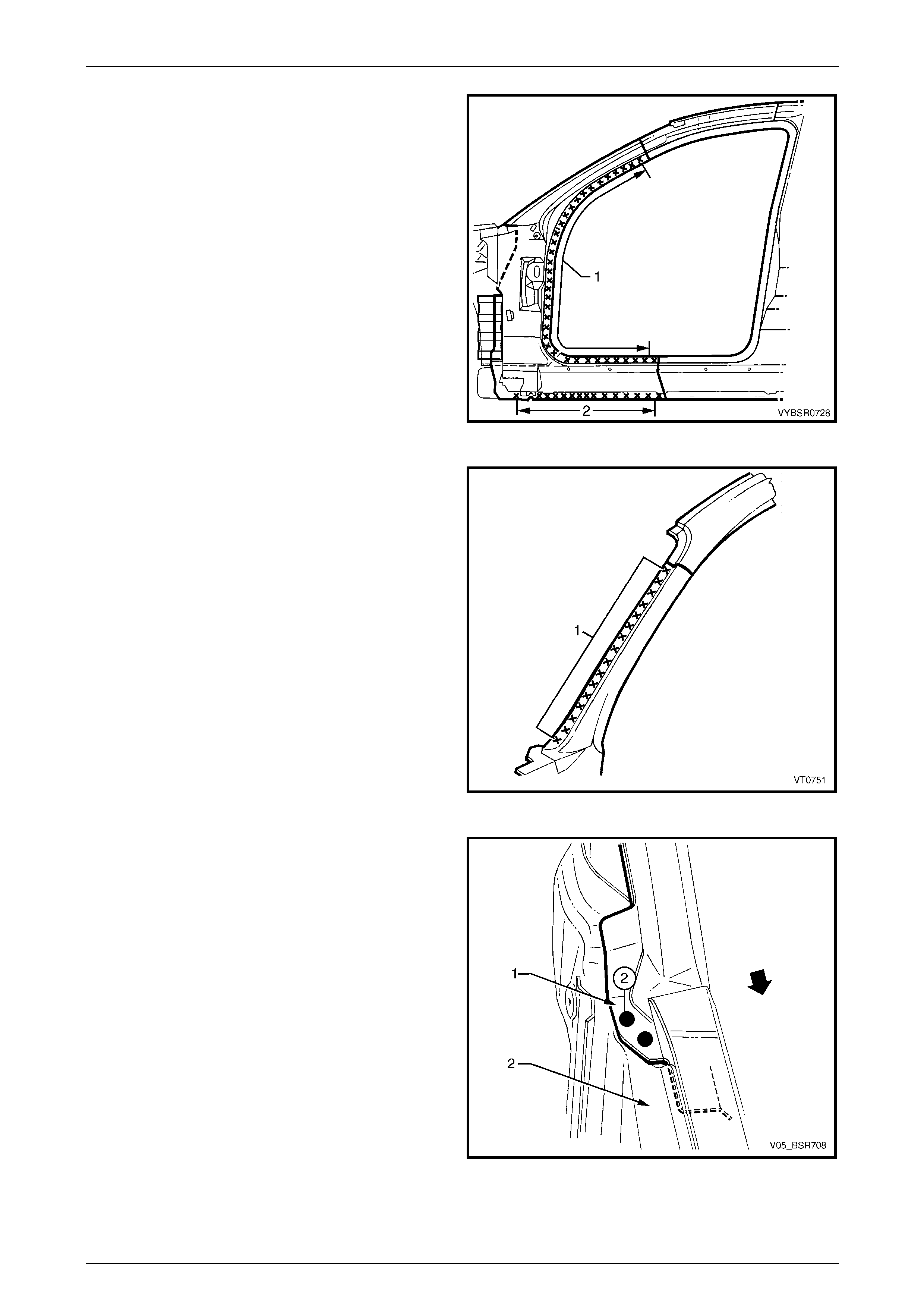
12 Cut through the rocker panel section of the frame door
opening assembly. The cut point (1) should be
approximately 100 mm from the dimple (2) on the
flange. Cut through both the outer pane l and the
reinforcement panel.
Figure 7C – 66
13 Spot cut the welds on the flange along the front door
opening, from the cut near the top of the hinge pill ar
(1) to the cut in the rocker panel (2).
14 Spot cut the welds along the flange (3) below the
rocker panel (to the point of the cut), separ ating the
door opening frame assembly from the inner rocker
panel.
15 Remove the partial hinge p illar from the vehicle, then
repair any damage to adjacent parts.
16 Check and rectify the alignme nt of
the body as requir ed,
refer to Section 3C Body Construction – Utility.
Figure 7C – 67
7C Body Side – Utility Page 7C-35
Page 7C-35
Replace
NOTE
• Spot welding is the preferred method for
attaching of panels and should be used
whenever possible. Where the spot welding
equipment available will not access the
required weld position, a plug weld should be
performed.
• The same number and position of spot welds
(or plug welds) should be used when
replacing the panel, as was used during
manufacture, in order to maintain the original
structural strength of the vehicle.
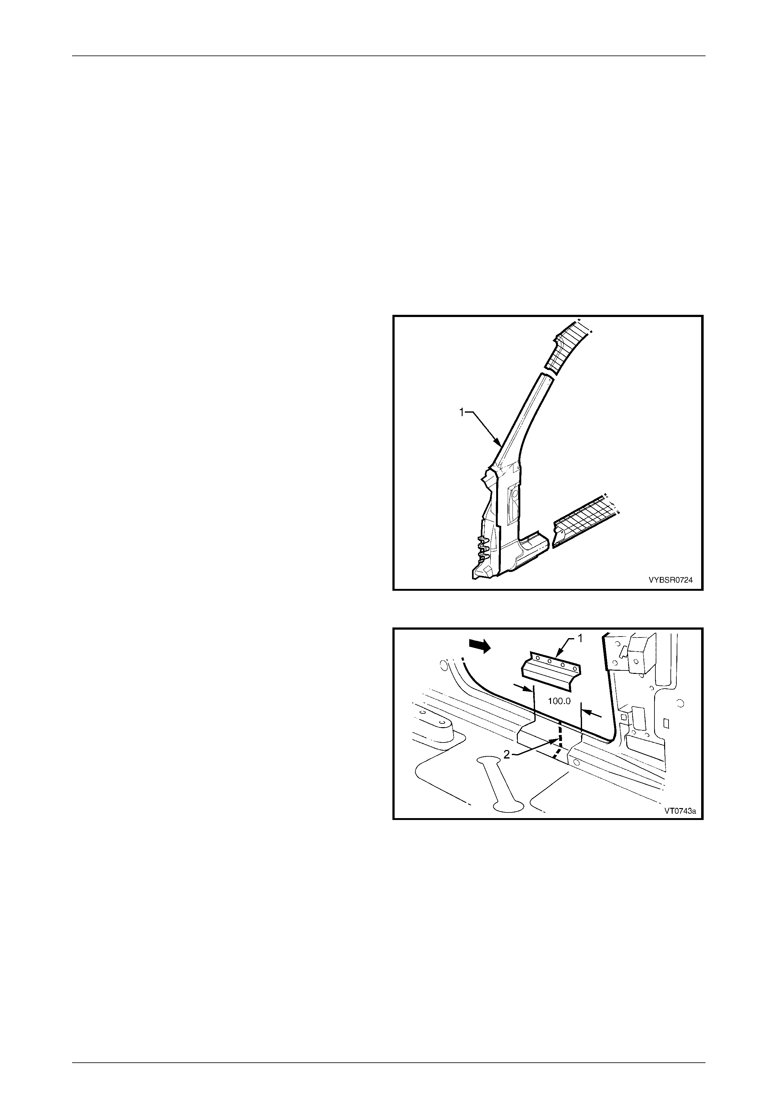
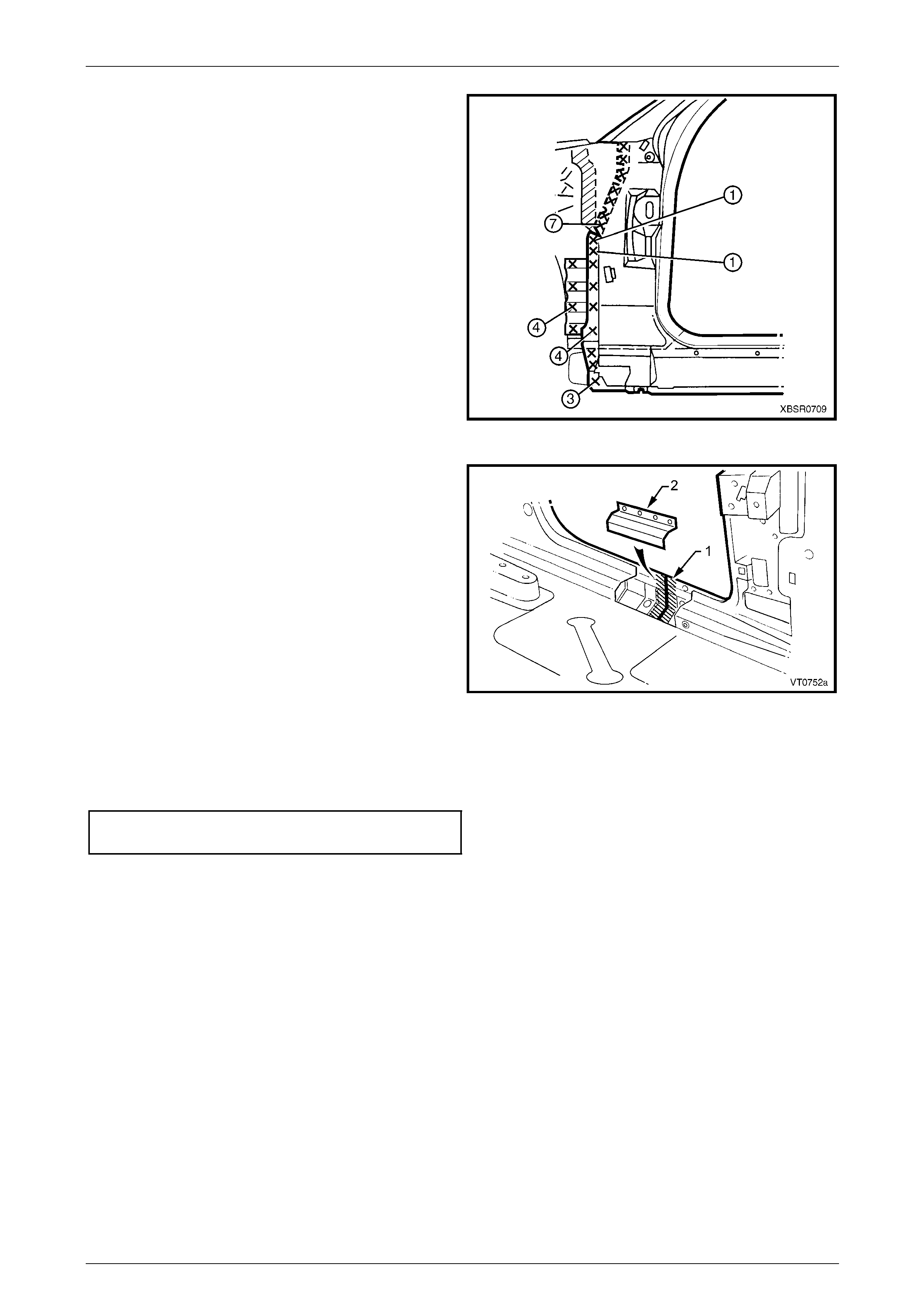
1 Cut a replacement panel section (1), accurately
measuring the position of cuts to match the section
removed.
Figure 7C – 68
2 Remove a section of inner rocker panel (1), cut 50 mm
each side of the cut in the rocker panel (2). This all ows
access for welding the rocker panel reinf orcement.
Figure 7C – 69
7C Body Side – Utility Page 7C-36
Page 7C-36
3 Either manufacture a new section or cut an existing
length of surplus rocker panel section, to form a
reinforcement (1), approximately 100 mm in length.
4 Prepare all mating surfaces and treat with Weld
Through Primer (Item 1) as required,
refer to Section 3C Body Construction – Utility.
5 Clamp this reinforcement firmly behind the cut section
of rocker panel on the vehicle and spot or plug weld in
place. Position welds at a maximum spacing of 35 mm
apart.
Figure 7C – 70
6 Using a similar technique, ma nufacture or cut a
section of reinforcement panel (1) appro ximat ely
60 mm long, to fit on the inside the outer panel of the
replacement hinge pillar (2) at the point of th e cut.
NOTE
Remove the flanges from this reinforcement
panel.
7 Prepare all mating surfaces and treat with Weld
Through Primer (Item 1) as required,
refer to Section 3C Body Construction – Utility.
8 Clamp the reinforcement panel firmly behind the outer
panel of the cut section of the hinge pillar and spot
weld (3) in place.
9 Mark the new hinge pillar with drilling locations in
preparation for plug welding where required. Drill holes
as marked.
10 Prepare all mating surfaces and treat with Weld
Through Primer (Item 1) as required,
refer to Section 3C Body Construction – Utility.
11 Apply Acrylic Spot Weld Sealer (Item 2),
refer to Section 3C Body Construction – Utility.
Figure 7C – 71
12 Clamp the replacement panel in position on the
vehicle and check the door opening dimensions.
Refer to Section 3C Body Construction – Utility. Adjust
position as required.
Figure 7C – 72
7C Body Side – Utility Page 7C-37
Page 7C-37
13 Plug weld (1) the top of the pillar to the manufactured
reinforcement, then MIG butt weld (2) the two sections
together.
Figure 7C – 73
14 Plug weld (1) the new panel in the rocker panel region,
then MIG butt weld (2) the two sections together.
Figure 7C – 74
15 Gaining access through the removed sectio n of inner
panel, MIG butt weld (1) the reinforcement panel
together.
16 Butt weld the removed access panel (2) in position.
Replace the spot welds with the same number that
was removed.
Figure 7C – 75
7C Body Side – Utility Page 7C-38
Page 7C-38
17 Spot weld (1) the hinge pillar section along the door
opening flange.
18 Spot weld (2) the flange beneath the rocker pan el,
attaching the new panel to the inner rocker panel.
Figure 7C – 76
19 Spot weld (1) the pillar along the windshield opening
flange.
Figure 7C – 77
20 Spot weld in two places at the base of the hinge pillar,
attaching the door opening frame assembly (1) to the
hinge pillar inner panel assembly (2).
Figure 7C – 78
7C Body Side – Utility Page 7C-39
Page 7C-39
21 Spot or plug weld the door opening frame assembly to
the inner rocker panel and to the hinge pillar inner
panel assembly. If the sheetmetal was modified to
allow access to these welds, it should be repaired to
its original configuration.
Figure 7C – 79
22 Gaining access through the section of removed in ner
rocker panel, MIG butt weld (1) the new section of
rocker panel reinforcement to the existing section.
23 Replace the removed section of inner rocker panel (2)
by MIG butt welding it in place and spot welding it
along the door opening flange. Replace the spot welds
with the same number of as were cut out.
24 Install the door hinges,
refer to Section 8 Doors, Liftgate and Endgat e.
25 Refinish and paint panels and other components as
required. Refer to Section 3 Body Construction .
26 Apply Joint Sealer (Item 3) as required.
Refer to Section 3C Body Construction – Utility. Figure 7C – 80
27 Apply Cavity Wax (Item 8) as required to the inside of any box secti ons or areas inaccessible to paint,
refer to Section 3C Body Construction – Utility.
28 Install the dash panel bolt through the hinge pillar and tighten to the specified torque.
Dash Panel Retaining Bolt
Torque Specification ...............................35.0 – 45.0 Nm
29 Replace the windshield, refer to Section 1A6 Stationary Windows in the MY2005 VZ Service Information.
30 Insert Cavity Foam into the hinge pillar as required, refer to Section 2 Precautions.
31 Install the remaining components as described in the appr opriate Section of the MY2005 VZ Service Information.
7C Body Side – Utility Page 7C-40
Page 7C-40
2.8 Door Opening Frame Assembly – Partial
Replace, Centre Pillar
NOTE
Cavity Foam is used within the hinge, centre and
lock pillar cavities. Care is required when
repairing the vehicle in these areas, refer to
Section 2 Precautions prior to beginning any work
for further information.
Remove
1 Remove the adjacent bolt-on panels a nd components
as described in the appropriate Section of the MY2005
VZ Service Information.
2 Install the vehicle on a suitab le fixture. As a minimum,
support the appropriate structural sections of the
vehicle on safety stands. Secure a suitable tool
between the front door openi ng flanges to maintain
alignment.
3 Remove the rear quarter panel,
refer to 2.1 Rear Quarter Panel – Replace.
Figure 7C – 81
4 Cut the door opening frame a ssembly (1) as shown.
NOTE
The upper cut is just below the recess and the
lower cut is approximately level with the centre
pillar upper reinforcement.
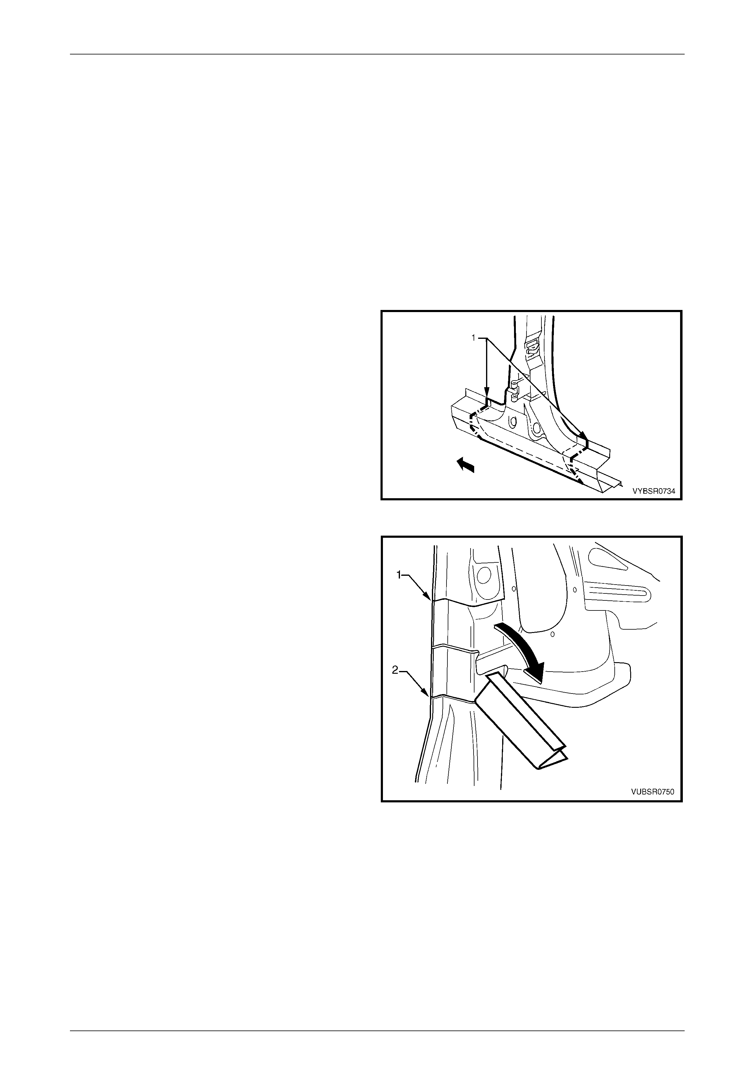
5 Spot cut the two welds attaching door opening frame
assembly to the centre pillar reinforcement.
6 Spot cut the welds attaching the door openin g frame
assembly to the quarter panel inner assembly.
7 Referring to Figure 7C – 83, spot cut the welds
attaching the underbody jacking locator (1) and
remove.
8 Referring to Figure 7C – 83, cut through the door
opening frame assembly (2) in two places shown (3):
• At the join of the rocker panel reinforcement (4)
and centre pillar lower reinforcement (5) for the
front cut, and
• At the dimple in the flange for the rear cut.
Figure 7C – 82
NOTE
Make the front cut carefully as the rocker panel
reinforcement (4) must not be cut. The centre
pillar lower reinforcement (5) is removed with the
centre pillar section.
9 Spot cut the welds on the flange attaching the centre pillar section to the inner rocker panel (6).
Refer to weld group A.
10 Spot cut the welds on the underside of the rocker panel attachi ng the centre pillar section to the quarter panel inner
assembly (7). Refer to weld group B.
7C Body Side – Utility Page 7C-41
Page 7C-41
Figure 7C – 83
11 Spot cut the welds attaching the front and rear sides of
the door opening frame assembly to the quarter panel
inner assembly.
NOTE
The number of welds will vary depending on the
cut locations.
12 Spot cut the four welds attaching the centre pillar
upper reinforcement to the centre pillar reinforcement.
13 Remove the centre pillar section from the vehicle.
14 Repair any damage to adjacent parts as required.
Figure 7C – 84
7C Body Side – Utility Page 7C-42
Page 7C-42
Replace
NOTE
• Spot welding is the preferred method for
attaching of panels and should be used
whenever possible. Where the spot welding
equipment available will not access the
required weld position, a plug weld should be
performed.
• The same number and position of spot welds
(or plug welds) should be used when
replacing the panel, as was used during
manufacture, in order to maintain the original
structural strength of the vehicle.
1 Cut the replacement door opening frame assembly
through rocker section as shown. Accurately measure
the position of cuts to match the removed panel
section.
Figure 7C – 85
2 Cut the replacement door opening frame assembly
below the recess to match the removed section from
the vehicle (1).
NOTE
Cut through the outer panel onl y.
3 Make a second cut approximately level with the centre
pillar upper reinforcement (2).
NOTE
Cut through the flange and front side onl y.
4 Cut the required spot welds and carefull y bend the
outer panel down to expose the spot welds attaching
the centre pillar upper reinforc ement to the centre
pillar reinforcement.
Figure 7C – 86
7C Body Side – Utility Page 7C-43
Page 7C-43
5 On the replacement panel, spot cut the five welds
attaching the centre pillar lower section to the centre
pillar upper reinforcement and remove the s ection.
Figure 7C – 87
6 Cut two sections from surplus rocker panel pieces, or
manufacture new sections (1), each ap proximately
100 mm in length.
7 Prepare the mating surfaces and treat with Weld
Through Primer (Item 1) as required,
refer to Section 3C Body Construction – Utility.
8 Clamp these sections firmly behi nd both the cut faces
of rocker panel on the vehicle and spot or plug weld in
place. Perform the welds at a maximum spacing of
35 mm.
9 Mark the new panel with drilling locations in
preparation for plug welding where required. Drill holes
as marked.
10 Prepare the mating surfaces and treat with Weld
Through Primer (Item 1) as required,
refer to Section 3C Body Construction – Utility.
Figure 7C – 88

7C Body Side – Utility Page 7C-44
Page 7C-44
11 Install the replacement panel i n position, sliding the
centre pillar reinforcement (1) and the centre pillar
lower reinforcement (2) behind the centre pillar upper
reinforcement (3), until the front edge of the lo wer
reinforcement butts against the front edge of the upper
reinforcement.
12 Manipulate the rocker panel section in position,
inserting the front first, then the rear and clamp the
assembly in place.
Figure 7C – 89
13 Plug weld the centre pillar upper reinforcement to the
centre pillar lower reinforcement, two places and the
centre pillar reinforcement two places.
Figure 7C – 90
14 Bend the outer panel back in position and MIG butt
weld the sections together as shown (1) and (2).
15 Plug weld the outer panel, centre pillar up per
reinforcement and centre pillar reinforcement two
places.
Figure 7C – 91
7C Body Side – Utility Page 7C-45
Page 7C-45
16 Plug weld (1) the front and rear sides of the door
opening frame assembly to the quarter panel inner
assembly.
NOTE
The number of welds will vary depending on the
cut locations.
17 Plug weld (2) the front and rear sides of the door
opening frame assembly to the rocker panel
reinforcements.
18 MIG butt weld (3) each join across the rocker panel.
Figure 7C – 92
19 Plug weld the flange attaching the centre pil lar section
(1) to the inner rocker panel (2).
Refer to weld group A.
20 Plug weld on the underside of the rocker panel the
centre pillar section to the quarter panel inner
assembly (3). Refer to weld group B.
21 Install the door hinges,
refer to Section 8 Doors, Liftgate and Endgat e.
22 Dress the welds by grinding or sanding, ensuring
sufficient material remains to guarantee the strength of
the weld. Finish the area using an appropriate
technique.
23 Refinish and paint panels and other components as
required. Refer to Section 3 Body Construction .
24 Apply Joint Sealer (Item 3) as required.
Refer to Section 3C Body Construction – Utility.
25 Apply Cavity Wax (Item 8) as required to the inside of
any box sections or areas inaccessible to paint,
refer to Section 3C Body Construction – Utility.
26 Insert Cavity Foam into the centre pillar as r equired,
refer to Section 2 Precautions.
27 Install the remaining components as described in the
appropriate Section of the MY2005 VZ Service
Information.
Figure 7C – 93
7C Body Side – Utility Page 7C-46
Page 7C-46
2.9 Door Opening Frame Assembly – Partial
Replace, Rocker Panel
As there are several critical reinforcements in
the lower hinge pillar area, the rocker panel
section must not be cut forward of the area
shown. If the rocker panel is damaged
forward of this area, replace the rocker panel
and partial hinge pillar as one section. Modify
this procedure accordingly, also referring to
2.7 Door Opening Frame Assembly – Partial
Replace, Hinge Pillar.
Remove
1 Remove the adjacent bolt-on panels a nd components
as described in the appropriate Section of the MY2005
VZ Service Information.
2 Remove the rear quarter panel,
refer to 2.1 Rear Quarter Panel – Replace.
3 Secure the vehicle on a suitable fixture. As a
minimum, support the appropriate structural s ections
of the vehicle on safety stands. Install suitable bracing
in the vehicle to ensure the correct body alignment is
maintained when the rocker pane l section is removed.
4 Remove the rear quarter panel,
refer to 2.1 Rear Quarter Panel – Replace.
Figure 7C – 94
5 Cut through the door opening frame assembly (1) and
the rocker panel reinforcement, no further forward than
the dimple in the flange (2).
Figure 7C – 95
7C Body Side – Utility Page 7C-47
Page 7C-47
6 Using a suitable cutting tool, cut through the centre
pillar. Cut through both the door opening frame (1) and
centre pillar lower reinforcement (2).
Figure 7C – 96
7 If required, select a cutting point through the rocker
panel, anywhere rearward of the dimple (1) i n the
flange. Cut through the door opening frame assembly
(2) only.
NOTE
If required, it may be preferable to remove the
complete rear section.
Figure 7C – 97
8 Depending on the cut location, spot cut any welds
remaining around the wheelhouse as required (most
would have been removed with the rear quarter
panel), attaching the door opening frame assembly (1)
to the quarter panel inner assembly (2).
9 Spot cut along the flange below the rocker panel as
required, to separate the rocker pan el section
(including the underbody jacking locator) from the
inner rocker panel and quarter panel inner assembly.
Refer to Figure 7C – 99.
NOTE
Some of these welds may have been previously
removed with the rear quarter panel.
Figure 7C – 98
7C Body Side – Utility Page 7C-48
Page 7C-48
Figure 7C – 99
10 Spot cut the welds attaching the rocker panel section to the quarter p an el inner assembly as required.
Refer to Figure 7C – 100.
NOTE
Depending on t he cut line position, ma ny of these
welds may have been previously removed if the
rear quarter panel has been remove d.
Figure 7C – 100
11 As required, spot cut the welds along the edge of the door ope ning frame assembly, refer to Figure 7C – 101.
12 Remove the panel from the vehicle, then repair any damage to adjac ent parts.
13 Check and rectify the alignme nt of the body as required, refer to Section 3 C Body Construction – Utility.
Figure 7C – 101

7C Body Side – Utility Page 7C-49
Page 7C-49
Replace
NOTE
• Spot welding is the preferred method for
attaching of panels and should be used
whenever possible. Where the spot welding
equipment available will not access the
required weld position, a plug weld should be
performed.
• The same number and position of spot welds
(or plug welds) should be used when
replacing the panel, as was used during
manufacture, in order to maintain the original
structural strength of the vehicle.
1 Cut a new replacement rocker panel section. Accuratel y measure the p ositi on of the cuts on the removed section.
2 Remove a section of inner rocker panel (1), cut 50 mm
each side of the cut in the rocker panel. This allows
access for welding the rocker panel reinf orcement.
Figure 7C – 102
3 Manufacture or cut a reinforcement (1) (appr oximately
100 mm long) to fit on the inside of the existing rocker
panel at the point of the cut.
4 Prepare the mating surfaces and treat with Weld
Through Primer (Item 1) as required,
refer to Section 3C Body Construction – Utility.
5 Clamp the manufactured reinforcement firmly to the
inside of the rocker panel section of the d oor opening
frame assembly on the vehicle and plug weld in
position. Position welds at a maximum sp acing of
35 mm.
6 If the rear section has been cut, repeat the above
steps for the rear join. Figure 7C – 103
7 Manufacture or cut a reinforcement (1) (appr oximately
100 mm long) to fit inside of the existing centre pillar
section at the point of the cut.
8 Prepare the mating surfaces and treat with Weld
Through Primer (Item 1) as required,
refer to Section 3C Body Construction – Utility.
9 Clamp the manufactured reinforcement panel firmly to
the inside of the outer panel of the door opening frame
assembly on the vehicle and p lug weld in position.
Position welds at a maximum spacing of 35 mm.
10 Mark the replacement rocker panel section with drilling
positions in preparation for plug welding as required.
Figure 7C – 104
7C Body Side – Utility Page 7C-50
Page 7C-50
NOTE
The outer panel will be plug welded from the
outer side of the vehicle, while the rocker panel
and centre pillar reinforcements will be butt
welded from the inner side of the vehicle.
11 Prepare all mating surfaces and treat with Weld Through Primer (Item 1) as required,
refer to Section 3C Body Construction – Utility.
12 Apply Acrylic Spot Weld Sealer (Item 2), refer to Section 3C Body Construction – Utility.
13 Install the replacement section onto the vehicle by sliding the front and centre pillar sections onto the
reinforcements, while lifting the rear into posi tion.
14 Clamp the panel in position.
15 Weld the new section to the centre pillar by plug
welding (1).
16 MIG butt weld the centre pillar reinforcement from
inside the centre pillar, through the large ho le in the
inner panel immediately behind the weld.
17 Finish the centre pillar attachment by MIG welding (2)
along the join of the outer panel.
Figure 7C – 105
18 Plug weld (1) the replacement section at the front join,
then MIG butt weld (2) the two sections together.
19 Repeat for the rear join if required.
Figure 7C – 106
7C Body Side – Utility Page 7C-51
Page 7C-51
20 Gaining access through the section of removed floor
side panel, MIG butt weld (1) the new section of rocker
panel reinforcement to the existing section.
21 Replace the removed section of floor side panel (2) by
MIG butt welding it in place and spot welding it along
the door opening flange. Repl ace the spot welds with
the same number as were removed.
22 Spot or plug weld the flanges of the door opening
frame assembly as required, refer to Figure 7C – 108.
NOTE
Use the same number and position of welds as
removed during removal. Figure 7C – 107
Figure 7C – 108
23 Spot or plug weld the door opening frame along the flange below the rocker panel as required,
refer to Figure 7C – 109.
NOTE
Place several welds only where the rear quarter
panel will overlap the flange to hold the
replacement section in position. Fully spot weld
this flange when the rear quarter panel is being
attached, welding through all panels.
Figure 7C – 109
7C Body Side – Utility Page 7C-52
Page 7C-52
24 Plug weld up through the rocker panel to attach the replacement section to the quarter panel inner assembly.
Refer to Figure 7C – 110.
NOTE
Place several welds only where the rear quarter
panel will overlap the flange to hold the
replacement section in position. Fully spot weld
this flange when the rear quarter panel is being
attached, welding through all panels.
Figure 7C – 110
25 If required, spot weld the replacement section to the
quarter panel inner assembly around the rear wheel
arch at several places to retain new section in position
NOTE
Fully spot weld this flan ge when the r ear quarter
panel is installed, welding through all three
panels.
26 Clean up the welds made where the rear quarter panel
is located and prime all bare metal.
27 Install the rear quarter panel,
refer to 2.1 Rear Quarter Panel – Replace.
28 Refinish and paint panels and other components as
required. Refer to Section 3 Body Construction .
29 Apply Joint Sealer (Item 3) as required.
Refer to Section 3C Body Construction – Utility.
30 Apply Cavity Wax (Item 8) as required to the inside of
any box sections or areas inaccessible to paint,
refer to Section 3C Body Construction – Utility.
31 Install the remaining components as described in the
appropriate Section of the MY2005 VZ Service
Information.
Figure 7C – 111
7C Body Side – Utility Page 7C-53
Page 7C-53
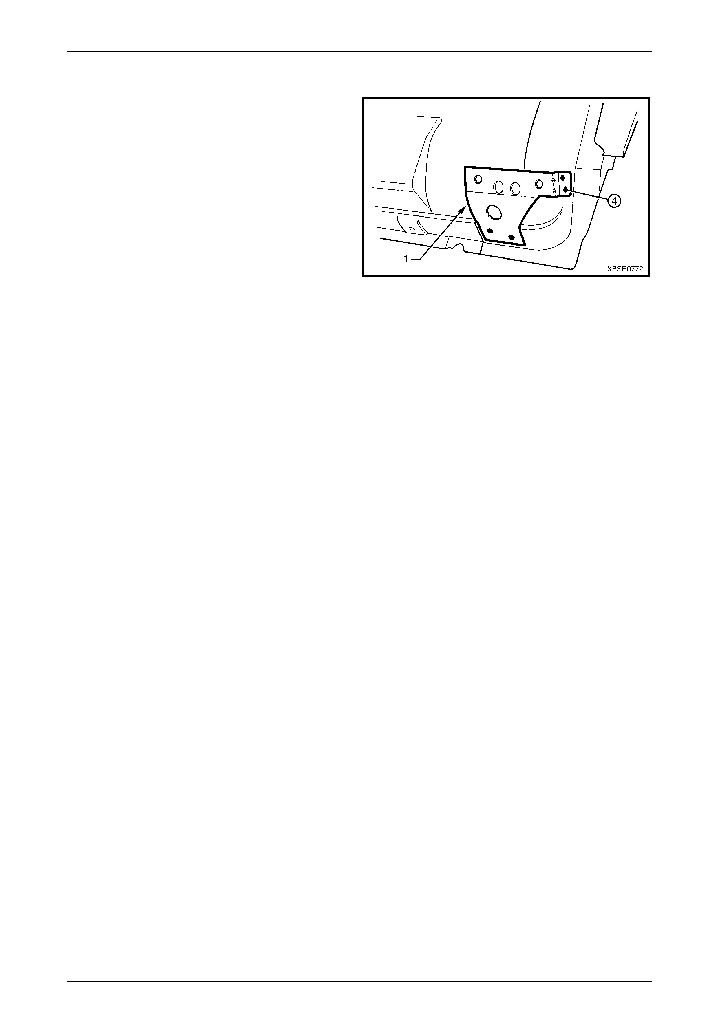
2.10 Fender Lower Rear Bracket – Replace
The fender lower rear bracket (1) is spot welded at four
places to the door opening fra m e assembly.
Clamp the fender lower rear bracket positi on as shown prior
to plug welding and check the alig nment of the fender to the
body and front door.
Refinish and paint panels and other components as
required. Refer to Section 3 Body Construction .
Apply Cavity Wax (Item 8) as r equired to the inside of any
box sections or areas inaccessible to paint,
refer to Section 3C Body Construction – Utility.
Figure 7C – 112
7C Body Side – Utility Page 7C-54
Page 7C-54
2.11 Hinge Pillar Inner Panel Assembly –
Replace
Remove
1 Remove the adjacent bolt-on panels a nd components
as described in the appropriate Section of the MY2005
VZ Service Information.
2 Remove the door opening frame assembly, refer to
2.6 Door Opening Frame Assembly – Repl ace, or
remove the hinge pillar section of the door opening
frame assembly, refer to 2.7 Door Opening Frame
Assembly – Partial Replace, Hinge Pil lar .
3 If required, remove the dash panel assembl y, refer to
Section 5 Cockpit Module in this Supplement.
NOTE
If the cockpit module is not damaged an
alternative is provided in this p rocedure.
4 Add bracing as requir ed to maintain the alignment of
the vehicle structure.
Figure 7C – 113
5 Grind the MIG welds (1) attaching the hinge pill ar inner
panel assembly to the inner rocker panel.
Figure 7C – 114
6 Spot cut the welds attaching the hinge pillar i nner
panel assembly to the roof front header and quarter
panel inner extension.
NOTE
Structural adhesive is applied to join (1). If the
roof panel has not been removed, it will be very
difficult to remove the panel. As an alternative:
• If only the lower section is damaged, detach
the hinge pillar inner upper panel (1) from the
hinge pillar inner lo wer panel (2) and replac e
the lower panel, or
• Cut the hinge pillar inner panel assembly (3)
approximately 50 mm from the top
of the windscreen aperture. If a partial
replacement of the door opening frame
assembly is being performed, this point is
50 mm above the cut in the outer panels (4).
Refer to Figure 7C – 116.
Figure 7C – 115

7C Body Side – Utility Page 7C-55
Page 7C-55
Figure 7C – 116
7 Spot cut the welds attaching the hinge pillar i nner
panel assembly to the front wheelhouse panel and
front floor panel extension, refer to weld group A.
8 If the dash panel assembly was not removed, spot cut
the eight welds attaching the adhesive channels to the
hinge pillar inner panel assembly,
refer to weld group B.
9 If required, remove any remainin g spot welds where
the wheelhouse panel upper side rail attached the
front wheelhouse panel a nd hinge pillar inner panel
assembly.
10 Cut the adhesive between the dash panel assembl y
and hinge pillar inner panel assembly.
11 Remove the hinge pillar in ner panel assembly from the
vehicle and as required, cle an off any remaining
adhesive and ensure the adhesive channels are
removed.
12 Repair any damage to adjacent parts as required. Figure 7C – 117

7C Body Side – Utility Page 7C-56
Page 7C-56
Replace
NOTE
• Spot welding is the preferred method for
attaching of panels and should be used
whenever possible. Where the spot welding
equipment available will not access the
required weld position, a plug weld should be
performed.
• The same number and position of spot welds
(or plug welds) should be used when
replacing the panel, as was used during
manufacture, in order to maintain the original
structural strength of the vehicle.
1 If an alternate removal method was used, referring to Figure 7C – 116, either:
• Cut the replacement section to match the cut at the top of the hinge pill ar, or
• Spot cut the welds attaching the hinge pillar i nner upper panel to the hinge pillar inner lower panel.
2 Mark the new panel and drill holes in preparation for plug welding where required.
3 Prepare all mating surfaces and treat with Weld Through Primer (Item 1) as required,
refer to Section 3C Body Construction – Utility.
4 If the dash panel assembly was removed, it will be installed later, proceed to Step 7.
5 If the dash panel assembly was not removed, prepare the adh esive channels on the replacement section and the
dash panel assembly, refer to Section 5 Cockpit Modu le .
6 Mix the dash panel silic one adhesive refer to Section 5 Cockpit Module . Apply the a dh esive to fill the adhesive
channels on the replaceme nt section.
NOTE
Only the correct material described in
Section 5 Cockpit Module is to be used.
7 If the full hinge pillar inner panel assembly is being replaced, apply structural adhesive (Item 6) to the mating
surfaces of the hinge pillar inner panel as sembly and quarter panel inner extension,
refer to Section 3C Body Construction – Utility.
7C Body Side – Utility Page 7C-57
Page 7C-57
8 Install and clamp the new panel in position on the
vehicle.
NOTE
If the dash panel assembly was not removed,
place the hinge pillar inner panel assembly (1)
slightly lower and slide it upwards ensuring the
dash panel flange (2) seats into the adhesive
channel.
9 Temporarily install the dash p anel attaching bolts
through the hinge pillar i nn er panel assembly and
within the plenum chamber.
10 Finish the application of the dash panel adhesive,
refer to Section 5 Cockpit Module .
Figure 7C – 118
11 If the full hinge pillar inner panel assembly was
removed, spot or plug weld the hinge pillar inner panel
assembly to the roof front header and quarter pane l
inner extension.
NOTE
Ensure the structural adhesive Item 6,
is applied to the join (1)
refer to Section 3C Body Construction – Utility
12 If only the lower section was removed, spot or plug
weld the hinge pillar inner upper panel (1) to the hinge
pillar inner lower panel (2), refer to Figure 7C – 120.
13 If the pillar was cut near the top of the windscreen
aperture, either MIG butt weld the join (3) if the full
door opening frame assembly was remov ed, or make
two tack welds to secure it until the door opening
frame assembly hinge pillar s ection is installed, also
refer to Figure 7C – 120.
Figure 7C – 119
NOTE
This join forms the top access cut point for
joining of the reinforcement as described in
2.7 Door Opening Frame Assembly – Partial
Replace, Hinge Pillar .
7C Body Side – Utility Page 7C-58
Page 7C-58
Figure 7C – 120
14 Spot or plug weld the hinge pillar in ner panel assembly
to the front wheelhouse panel and front floor
extension.
Figure 7C – 121
15 MIG weld two places (1) across the inner rocker panel
and hinge pillar inner panel assembly.
16 Replace the door opening fra me assembly, refer to
2.6 Door Opening Frame Assembly – Repl ace or the
hinge pillar section of the door opening frame
assembly, refer to 2.7 Door Opening Frame Assembly
– Partial Replace, Hinge Pill ar.
17 Refinish and paint panels and other components as
required. Refer to Section 3 Body Construction .
18 Apply Joint Sealer (Item 3) as required.
Refer to Section 3C Body Construction – Utility.
19 Apply Cavity Wax (Item 8) as required to the inside of
any box sections or areas inaccessible to paint,
refer to Section 3C Body Construction – Utility.
20 Install the remaining components as described in the
appropriate Section of the MY2005 VZ Service
Information.
Figure 7C – 122
7C Body Side – Utility Page 7C-59
Page 7C-59
2.12 Quarter Inner and Rear Wheelhouse
Brace – Replace
1 Remove the adjacent bolt-on panels a nd components
as described in the appropriate Section of the MY2005
VZ Service Information.
2 Remove the rear quarter panel,
refer to 2.1 Rear Quarter Panel – Replace.
Figure 7C – 123
3 Spot cut the welds attaching the quarter inner and rear
wheelhouse brace to the qu arter panel inner assemb ly
and side inner upper pa nel, 18 places.
4 If not previously done, spot cut the welds attaching the
quarter inner and rear wheelhouse brace to the side
inner upper panel, two places.
5 Remove the brace and rep air any adjacent damage as
required.
Figure 7C – 124
Replace
NOTE
• Spot welding is the preferred method for
attaching of panels and should be used
whenever possible. Where the spot welding
equipment available will not access the
required weld position, a plug weld should be
performed.
• The same number and position of spot welds
(or plug welds) should be used when
replacing the panel, as was used during
manufacture, in order to maintain the original
structural strength of the vehicle.
1 Mark the new panel with drilling locations in prep aration for plug welding. Drill holes as required.
2 Prepare all mating surfaces and treat with Weld Through Primer (Item 1) as required,
refer to Section 3C Body Construction – Utility.
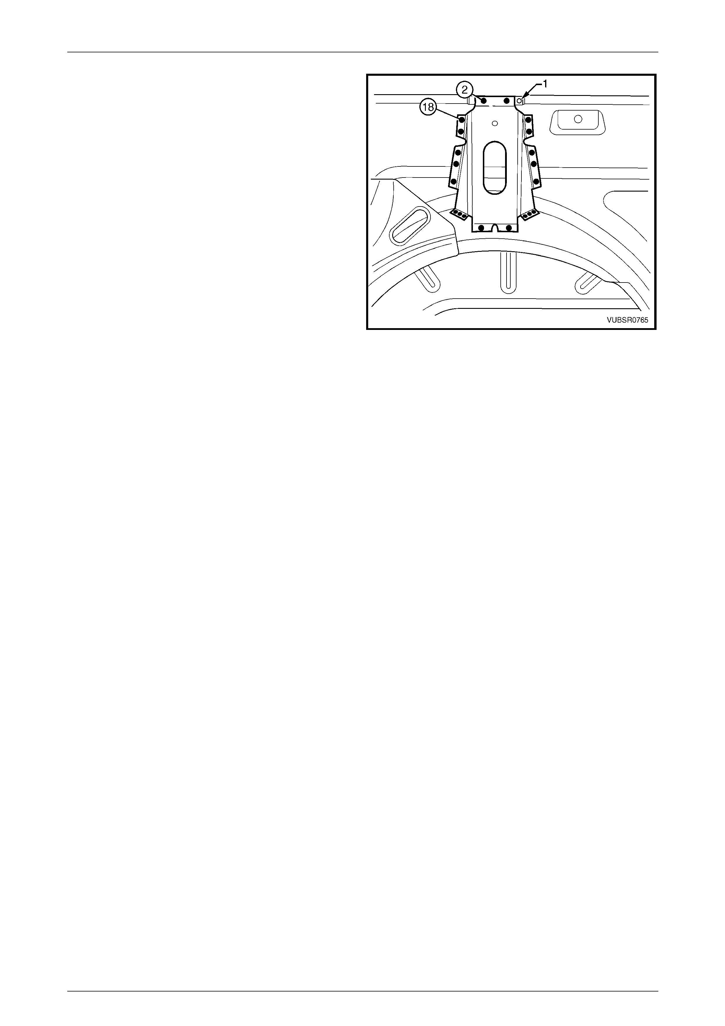
7C Body Side – Utility Page 7C-60
Page 7C-60
3 Install and clamp the brace in position ensuring it is
located forward of the side inner upper panel hole (1).
4 Spot or plug weld the brace to the side inner upper
panel and quarter, 18 places.
5 Clean up the welds and apply a coat of primer.
6 Install the rear quarter panel,
refer to 2.1 Rear Quarter Panel – Replace.
7 Refinish and paint panels and other components as
required. Refer to Section 3 Body Construction .
8 Apply Joint Sealer (Item 3) as required.
Refer to Section 3C Body Construction – Utility.
9 Apply Cavity Wax (Item 8) as required to the inside of
any box sections or areas inaccessible to paint,
refer to Section 3C Body Construction – Utility.
10 Apply Spray-on Dea dener (Item 7) where applicab le,
refer to Section 3C Body Construction – Utility.
11 Install the remaining components as described in the
appropriate Section of the MY2005 VZ Service
Information.
Figure 7C – 125
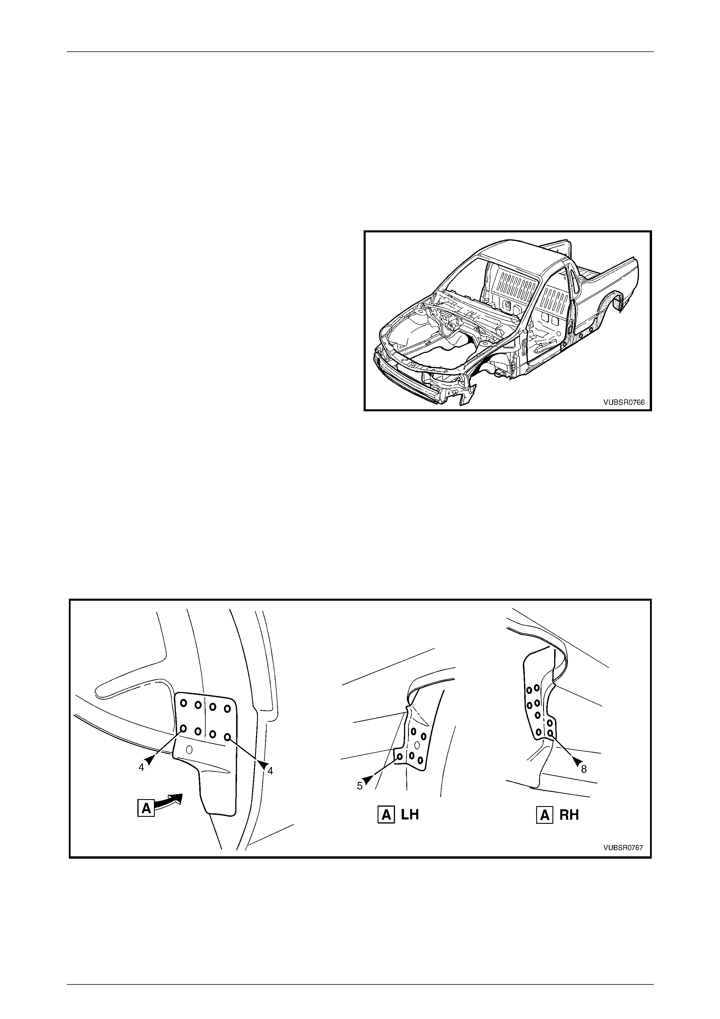
7C Body Side – Utility Page 7C-61
Page 7C-61
2.13 Quarter Panel Inner Assembly – Replace
NOTE
This procedure also includes the rear
wheelhouse bracket and rear wheelhouse outer
extension (righ t-hand side only).
Remove
1 Remove the adjacent bolt-on panels a nd components
as described in the appropriate Section of the MY2005
VZ Service Information.
2 Remove rear quarter panel,
refer to 2.1 Rear Quarter Panel – Replace.
3 Remove the door opening frame assembly, refer to
2.6 Door Opening Frame Assembly – Repl ace.
Figure 7C – 126
NOTE
If the damage is to the lower portion of the body,
the partial door opening frame assembly, hinge
pillar and rocker panel sections can be removed.
4 Remove the welds attaching the quarter inner and rear wheelhouse brace to the quarter panel inner asse mbly,
refer to 2.12 Quarter Inner and Rear Wheelhouse Brace – Replace.
5 Spot cut the welds attaching the rear wheelhouse bracket to the quarter panel inner assembly as required,
refer to Figure 7C – 127.
Figure 7C – 127
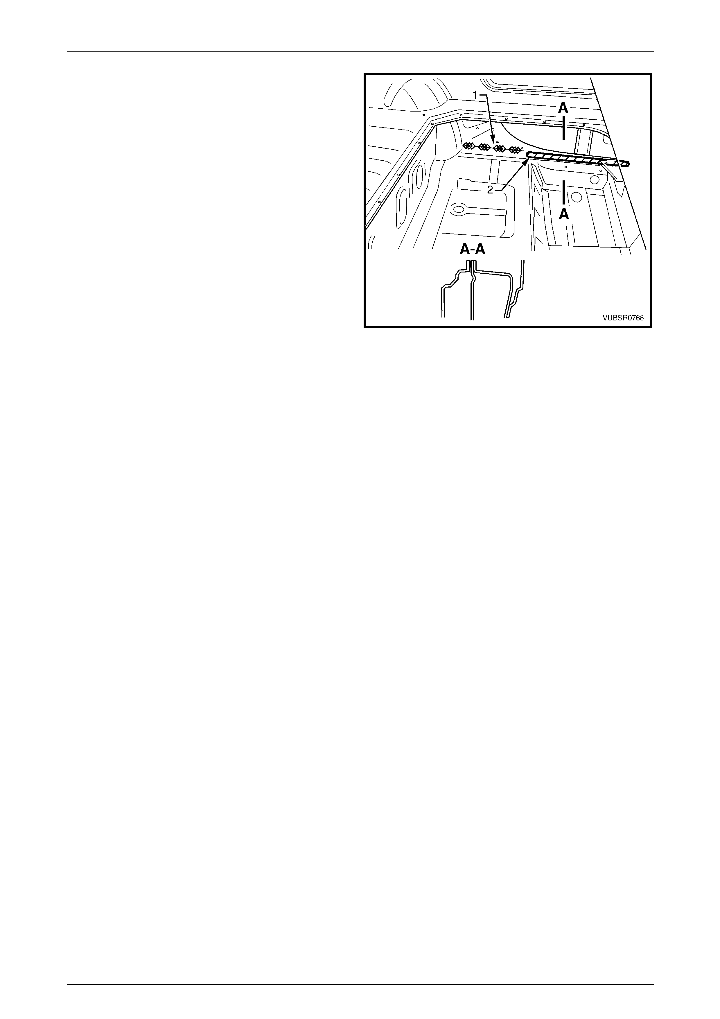
7C Body Side – Utility Page 7C-62
Page 7C-62
6 Grind the four MIG welds (1) from the inside of the
quarter panel inner assembly, joining the inner rocker
panel.
7 Structural adhesive (2) is applied along the flange
between the quarter panel in ner assembly and inner
rocker panel. Either cut the flange or cut arou nd the
adhesive and grind off the flange once the panel is
removed.
8 Spot cut the welds attaching the quarter panel inner
assembly to the side inner upper panel and side inner
upper front panel, refer to Figure 7C – 129.
NOTE
• If the partial door opening frame assembly
hinge pillar sect ion was removed, remov e the
welds attaching the hinge pillar upper
reinforcement to the quarter panel inner
assembly. Refer to 2.6 Door Opening Frame
Assembly – Replace and cut the welds
attaching the quarter panel inner assemb ly to
the side inner upper front panel from inside
the vehicle.
• For the right-hand side, either remove the
rear wheelhouse outer extension or spot cut
the 10 welds attaching it to the quarter panel
inner assembly.
Figure 7C – 128
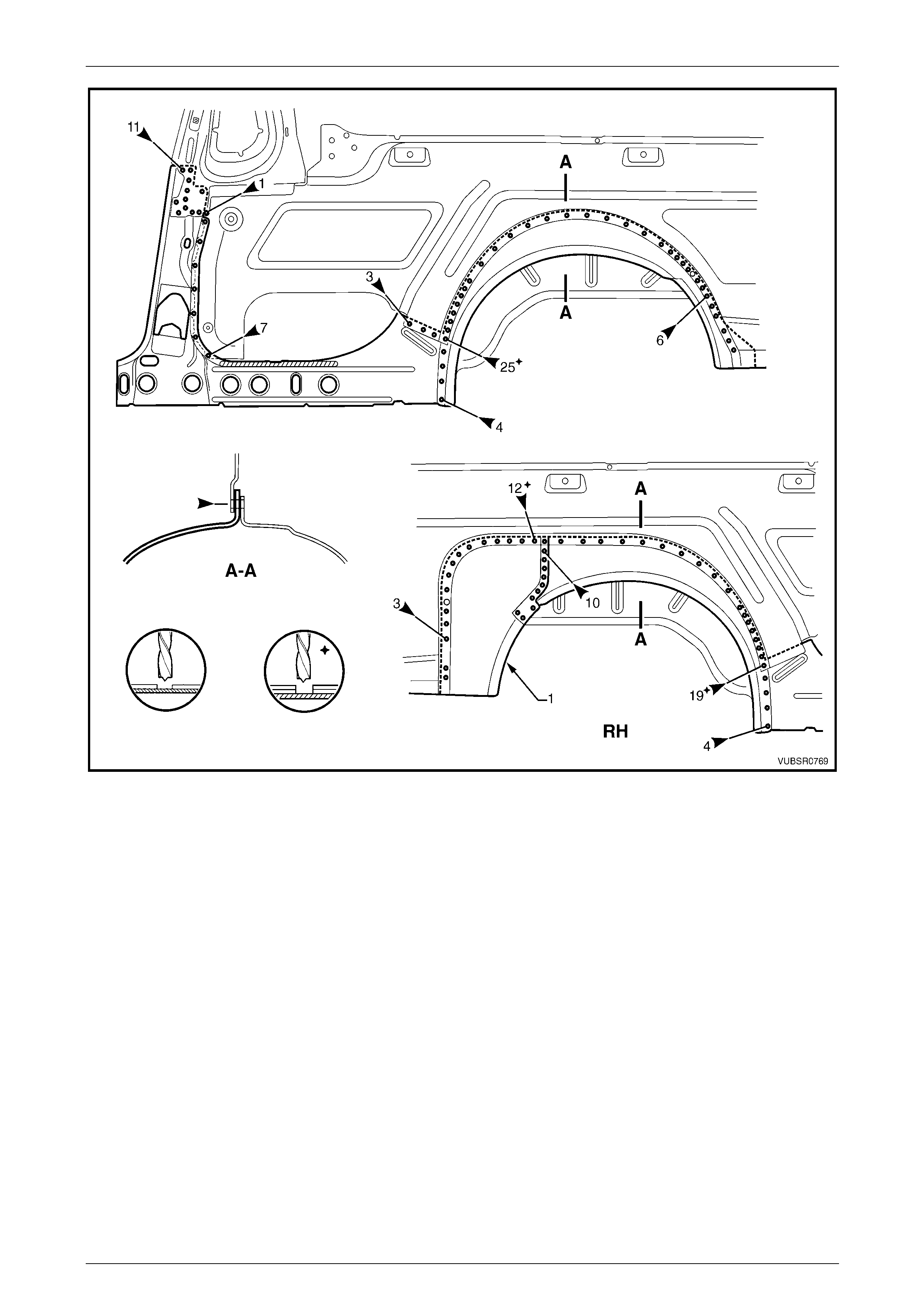
7C Body Side – Utility Page 7C-63
Page 7C-63
Figure 7C – 129
9 As required, spot cut any remaining welds from where the door opening frame assembly and re ar quarter panel
attached.
10 Remove the quarter panel inner assembly from the vehicle and repair any damage to adjacent parts as required.

7C Body Side – Utility Page 7C-64
Page 7C-64
Replace
NOTE
• Spot welding is the preferred method for
attaching of panels and should be used
whenever possible. Where the spot welding
equipment available will not access the
required weld position, a plug weld should be
performed.
• The same number and position of spot welds
(or plug welds) should be used when
replacing the panel, as was used during
manufacture, in order to maintain the original
structural strength of the vehicle.
1 Mark the new panel and drill holes in preparation for plug welding where required.
2 Prepare all mating surfaces and treat with Weld Through Primer (Item 1) as required,
refer to Section 3C Body Construction – Utility.
3 Apply structural adhesive (Item 6) to the mating surfac es of the quarter panel inner assembl y and inner rocker
panel, refer to Section 3C Body Construction – Utility.
4 Clamp the new panel in position on the vehicle.
5 Spot or plug weld the quarter panel in ner assembly, to the side inner upper panel and sid e inn er upper front panel,
refer to Figure 7C – 130.
NOTE
For the right-hand side, install the wheelhouse
outer extension (1) if removed, and weld to the
side inner upper panel.
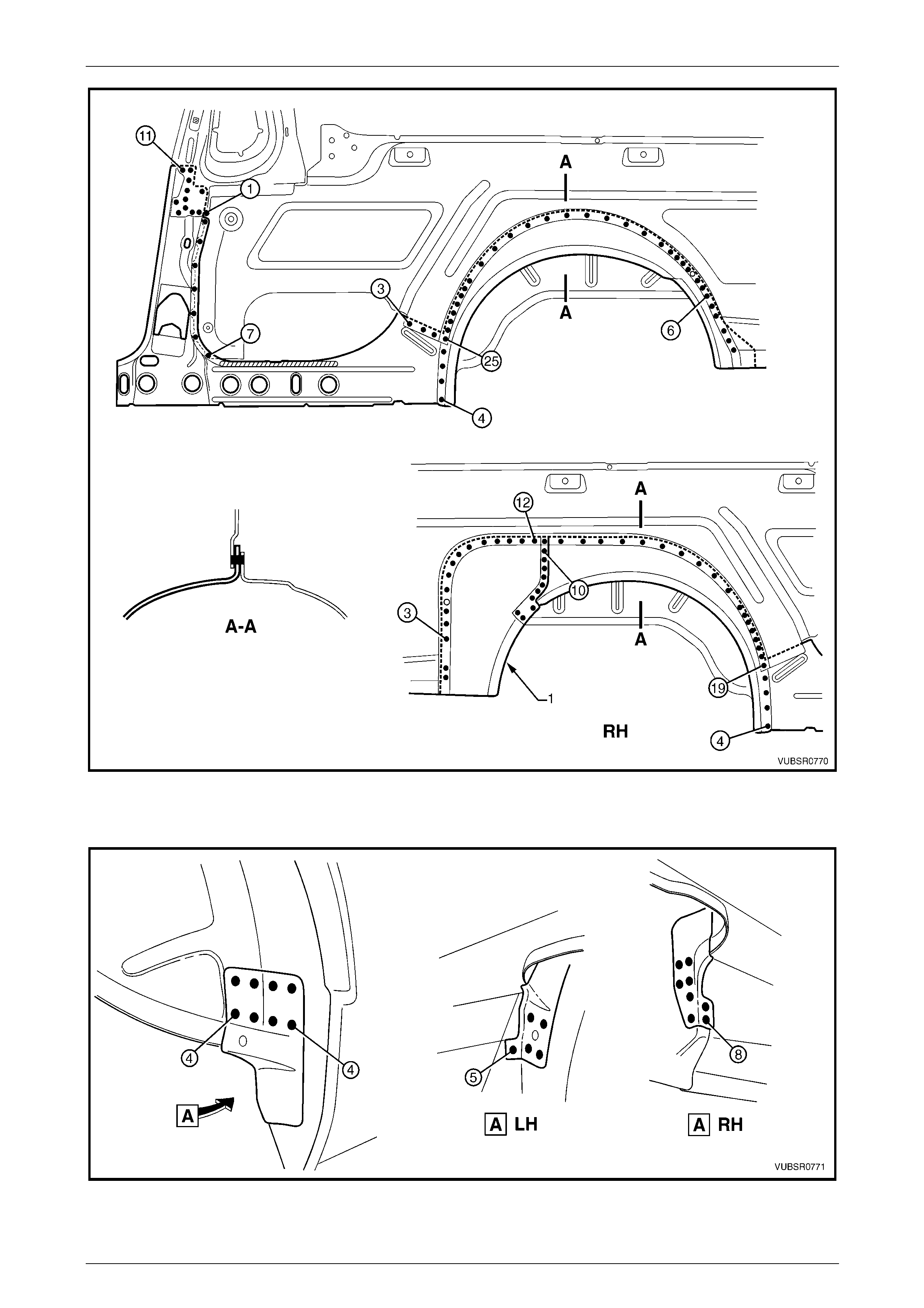
7C Body Side – Utility Page 7C-65
Page 7C-65
Figure 7C – 130
6 Spot or plug weld the rear wheelhous e bracket to quarter panel inner asse mbly, refer to Figure 7C – 131.
Figure 7C – 131
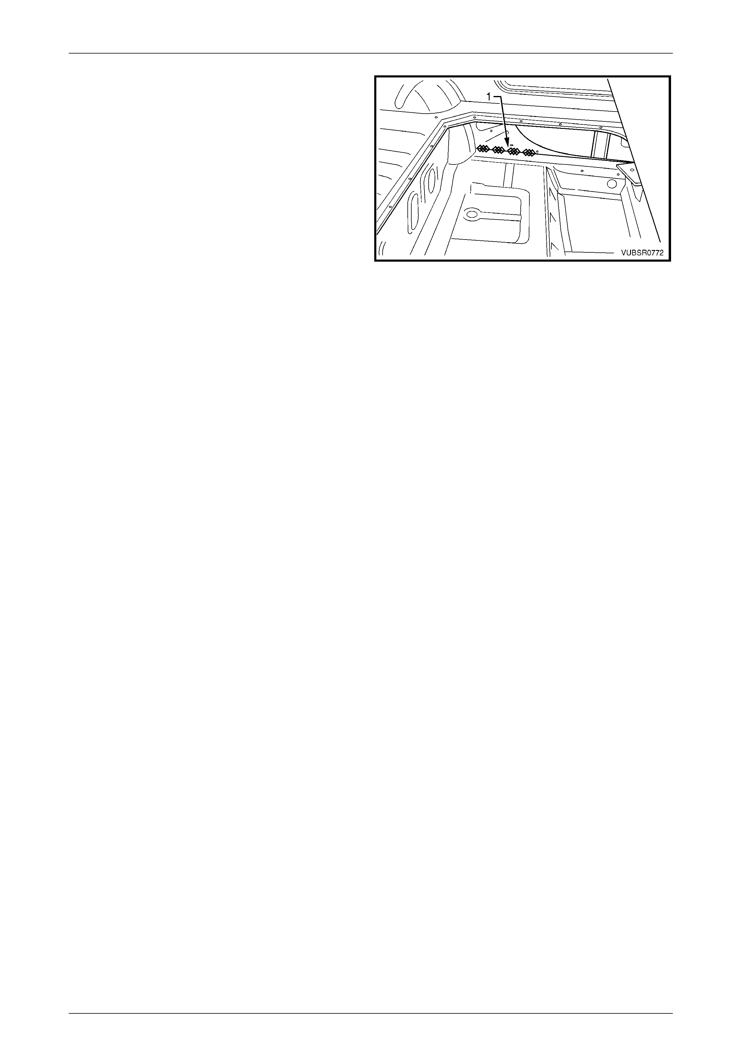
7C Body Side – Utility Page 7C-66
Page 7C-66
7 MIG weld four places 25 – 50 mm each, the quarter
panel inner assembly to the inner rocker pan el (1).
8 Spot or plug the quarter inner and rear wheelhouse
brace to the quarter panel inner assembly, refer to
2.12 Quarter Inner and Rear Wheel house Brace –
Replace.
9 If the centre pillar upper reinforcement was not
removed, spot or plug weld it to the quarter panel inner
assembly, refer to 2.6 Door Opening Frame Assembly
– Replace.
10 Clean up welds and prime any bare metal.
11 Replace the door opening fra me assembly, refer to
2.6 Door Opening Frame Assembly – Repl ace.
12 Replace rear quarter panel,
refer to 2.1 Rear Quarter Panel – Replace.
Figure 7C – 132
13 Refinish and paint panels and other components as required. Refer to Section 3 Body Construction.
14 Apply Joint Sealer (Item 3) as required. Refer to Section 3C Body Construction – Utility.
15 Apply Cavity Wax (Item 8) as required to the inside of any box secti ons or areas inaccessible to paint,
refer to Section 3C Body Construction – Utility.
16 Apply Spray-on Deadener (Item 7) to the wheel side of the rear wheelhouse,
refer to Section 3C Body Construction – Utility.
17 Install the remaining components as described in the appr opriate Section of the MY2005 VZ Service Information.
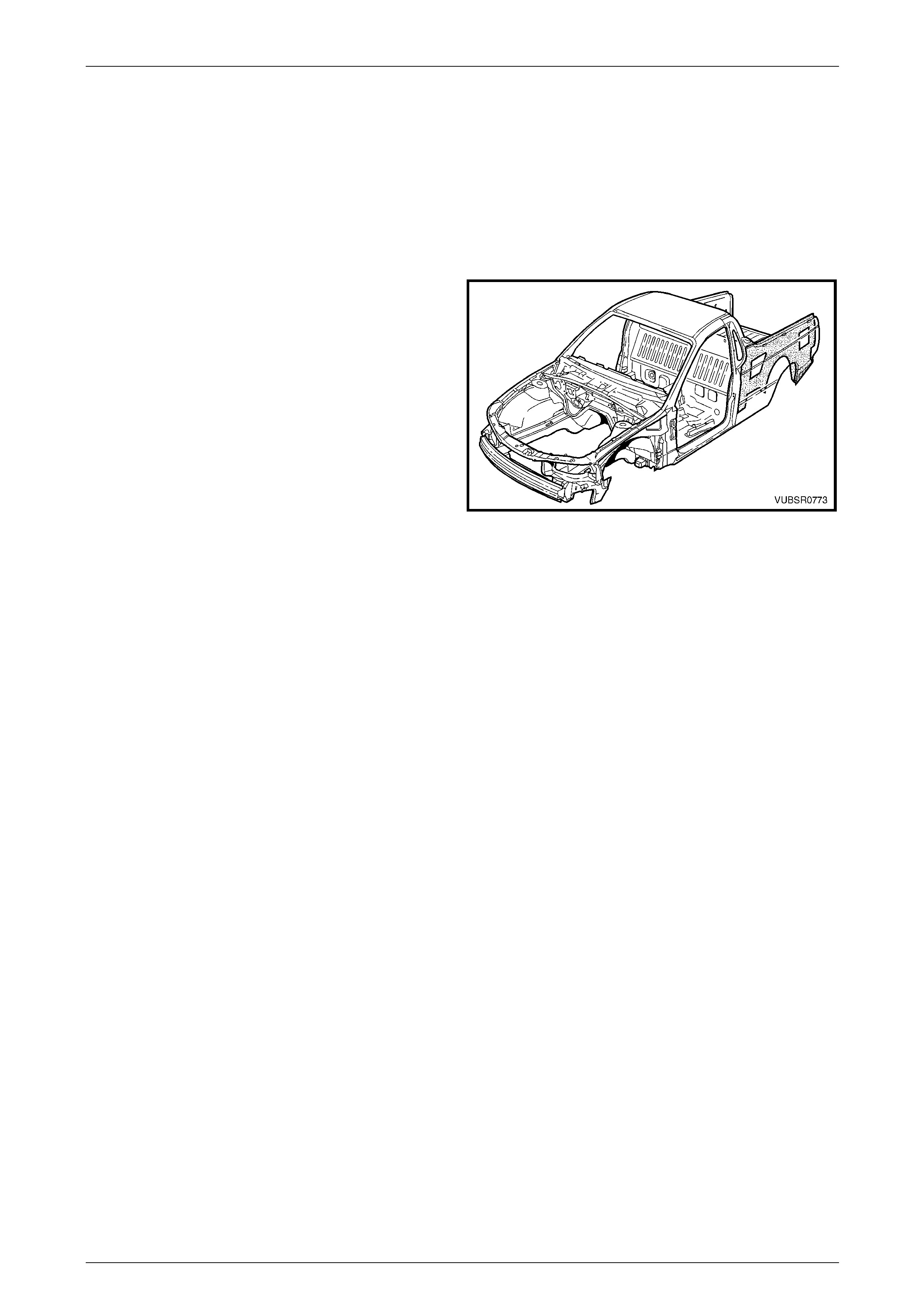
7C Body Side – Utility Page 7C-67
Page 7C-67
2.14 Side Inner Upper Panel – Replace
NOTE
This procedure also includes the cargo tie-down
brackets.
Remove
1 Remove the adjacent bolt-on panels a nd components
as described in the appropriate Section of the MY2005
VZ Service Information.
2 Mount the vehicle on a suitable jig to mai ntai n correct
body alignment when the side inner upper panel is
removed.
3 Remove the rear quarter panel,
refer to 2.1 Rear Quarter Panel – Replace.
4 Remove the quarter outer lower rear panel, refer to
2.4 Quarter Outer Lower Rear Panel – Replace.
Figure 7C – 133
5 Remove the quarter inner lower rear extension, refer to 2.3 Quarter Panel Inner Lower Rear Extension – Replace.
6 Remove the door opening frame assembly, refer to 2.6 Door Opening Frame Assembly – Rep lace.
NOTE
If required, the partial door opening frame
assembly centre pillar and rocker panel
sections can be removed. Spot cut the welds
attaching the remaining door opening frame
assembly to the side inner upper panel, refer to
2.6 Door Opening Frame Assembly – Repl ace.
7 Remove the quarter inner and rear wheelhouse brace,
refer to 2.12 Quarter Inner and Rear Wheelhouse Brace – Replace.
8 Remove the welds attaching the side inner upper panel to the quarter lower rear panel,
refer to 2.5 Quarter Lower Rear Panel – Replace.
9 Remove the welds attaching the side inner upper panel to the rear end panel,
refer to Section 10C Body Rear – Utility.
10 Spot cut the welds and grind off the MIG welds attaching the side inner upper panel to the load floor panel,
refer to Figure 7C – 134.
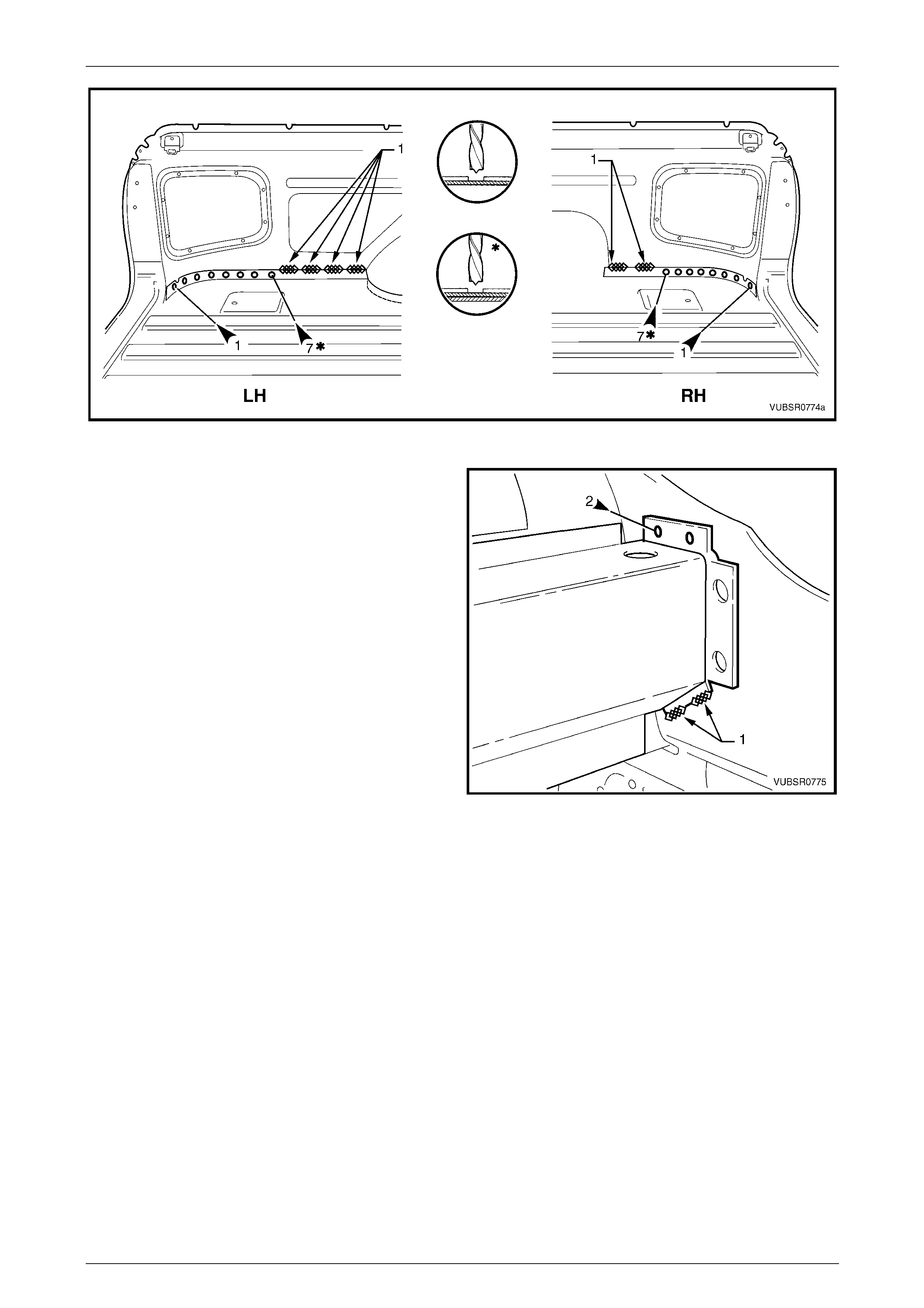
7C Body Side – Utility Page 7C-68
Page 7C-68
Figure 7C – 134
11 Spot cut the welds (if not already removed) and grind
off the MIG welds (1) attaching the inner upper side
panel to the load compartment extensio n panel.
12 Spot cut the welds attaching the side inner upper
panel to the quarter panel inner assembly, side inner
upper front panel, rear wheelhouse inner panel, load
floor panel outer extension and front seatback panel
outer, refer to Figure 7C – 136.
13 Remove the side inner upper panel from the vehicle
and repair any dama ge to adjacent parts as required.
Figure 7C – 135
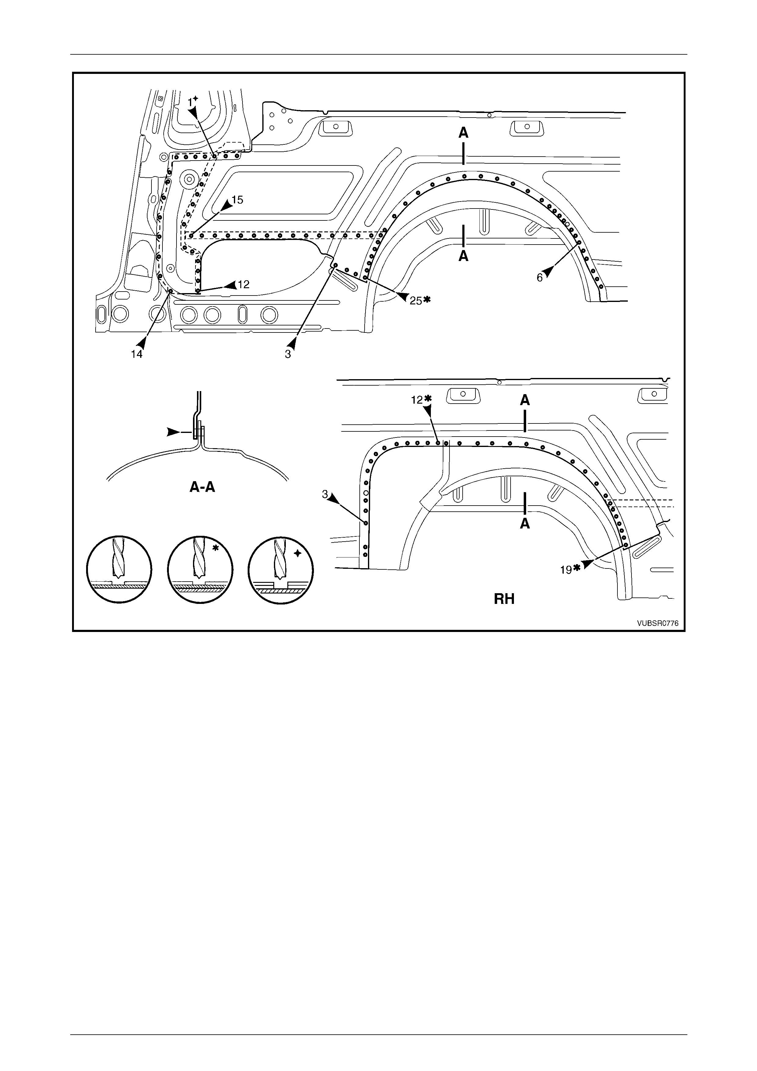
7C Body Side – Utility Page 7C-69
Page 7C-69
Figure 7C – 136
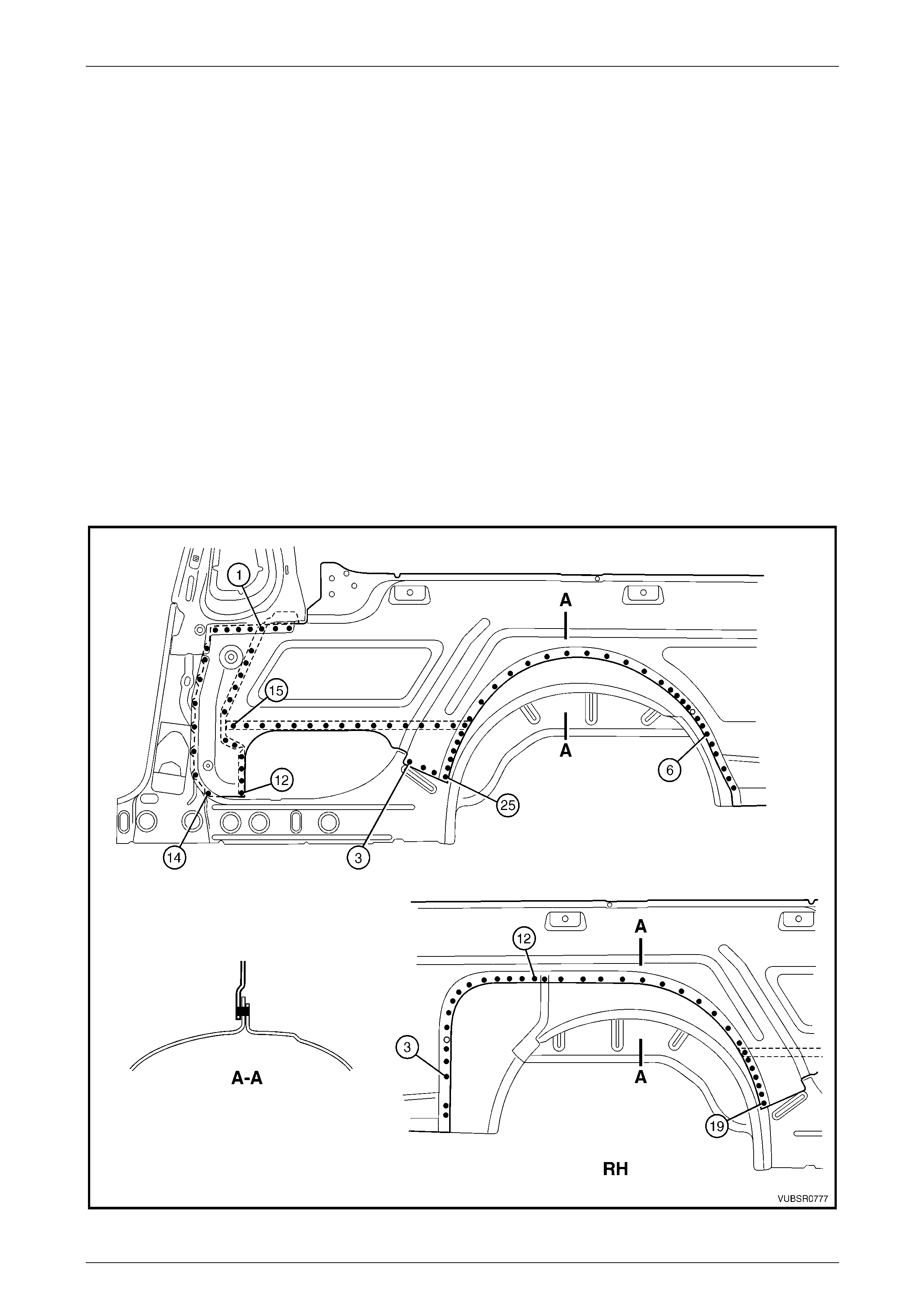
7C Body Side – Utility Page 7C-70
Page 7C-70
Replace
NOTE
• Spot welding is the preferred method for
attaching of panels and should be used
whenever possible. Where the spot welding
equipment available will not access the
required weld position, a plug weld should be
performed.
• The same number and position of spot welds
(or plug welds) should be used when
replacing the panel, as was used during
manufacture, in order to maintain the original
structural strength of the vehicle.
1 Mark the new panel with drilling locations in prep aration for plug welding. Drill holes as required.
2 Prepare all mating surfaces and treat with Weld Through Primer (Item 1) as required,
refer to Section 3C Body Construction – Utility.
3 Clamp the new panel in position on the vehicle.
4 Spot or plug weld the side inner upp er panel to the quarter panel inner assembly, side inne r upper front panel, rear
wheelhouse inner panel, load floor panel outer extension and front seatback panel outer, refer to F igure 7C – 137.
Figure 7C – 137
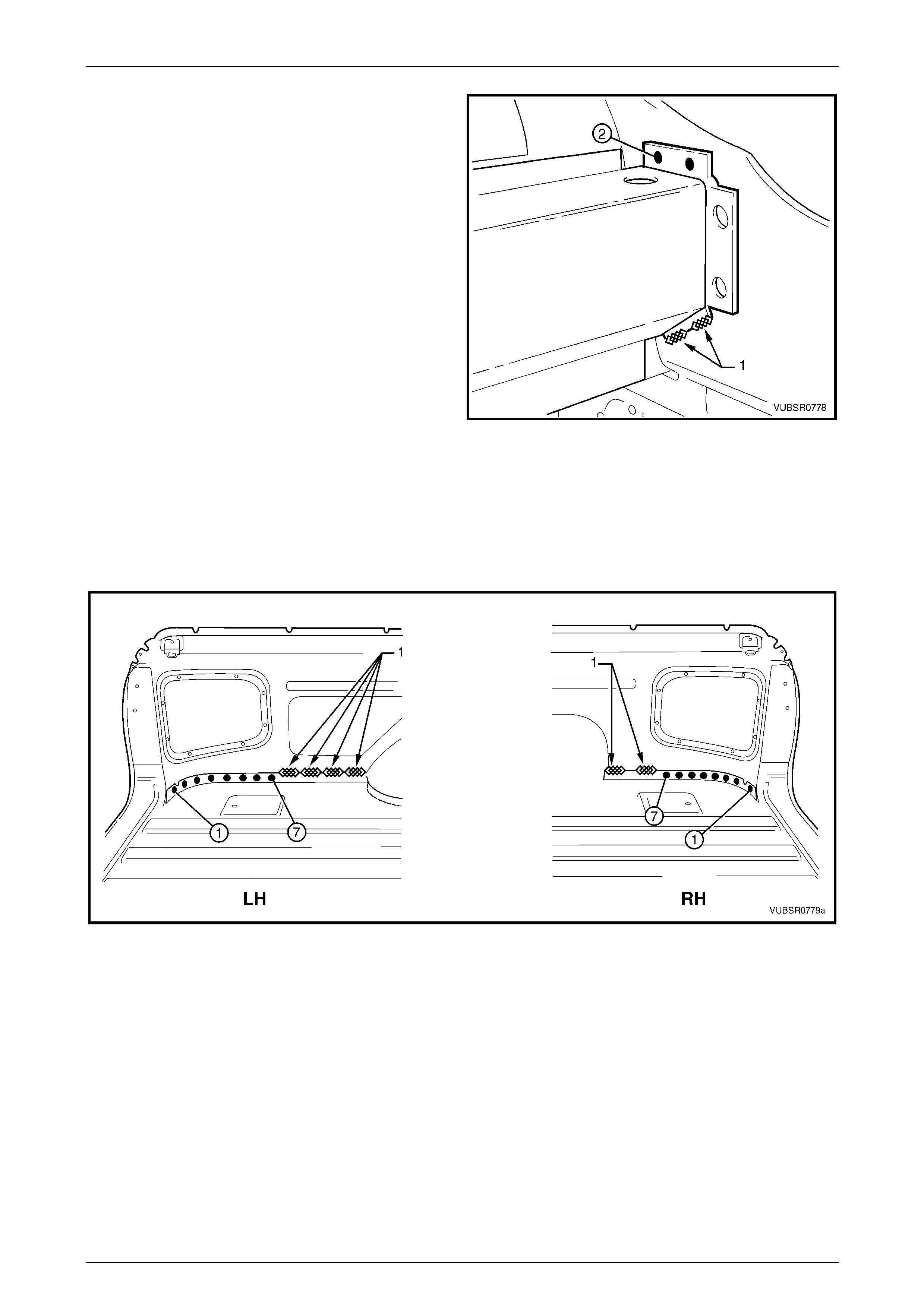
7C Body Side – Utility Page 7C-71
Page 7C-71
5 MIG weld (1) two places 15 – 20 mm each, the side
inner upper panel to the load compartment extension
panel.
NOTE
Make the two spot welds (2) once the door
opening frame assembly and rear quarter panel
have been installed.
6 MIG weld the right-hand side inner upper panel (1)
four places 25 – 50 mm each, or the left-hand side
inner upper panel (2) two places 25 – 50 mm each, to
the load floor panel, refer to Figure 7C – 139.
7 Install the quarter outer lower rear panel and spot or
plug to the side inner upper panel and l oad floor panel,
refer to Figure 7C – 139.
Figure 7C – 138
NOTE
Also refer to 2.4 Quarter Outer Lower Rear
Panel – Replace.
8 Spot or plug weld the side inner upper panel to the quarter lower rear panel,
refer to 2.5 Quarter Lower Rear Panel – Replace.
Figure 7C – 139
9 Spot or plug weld the side inner upper pa nel to the rear end panel, refer to Section 10C Body Rear – Util ity.
10 Install the quarter inner lower rear extension, refer to 2.3 Quarter Panel Inner Lower Rea r Extension – Replace.
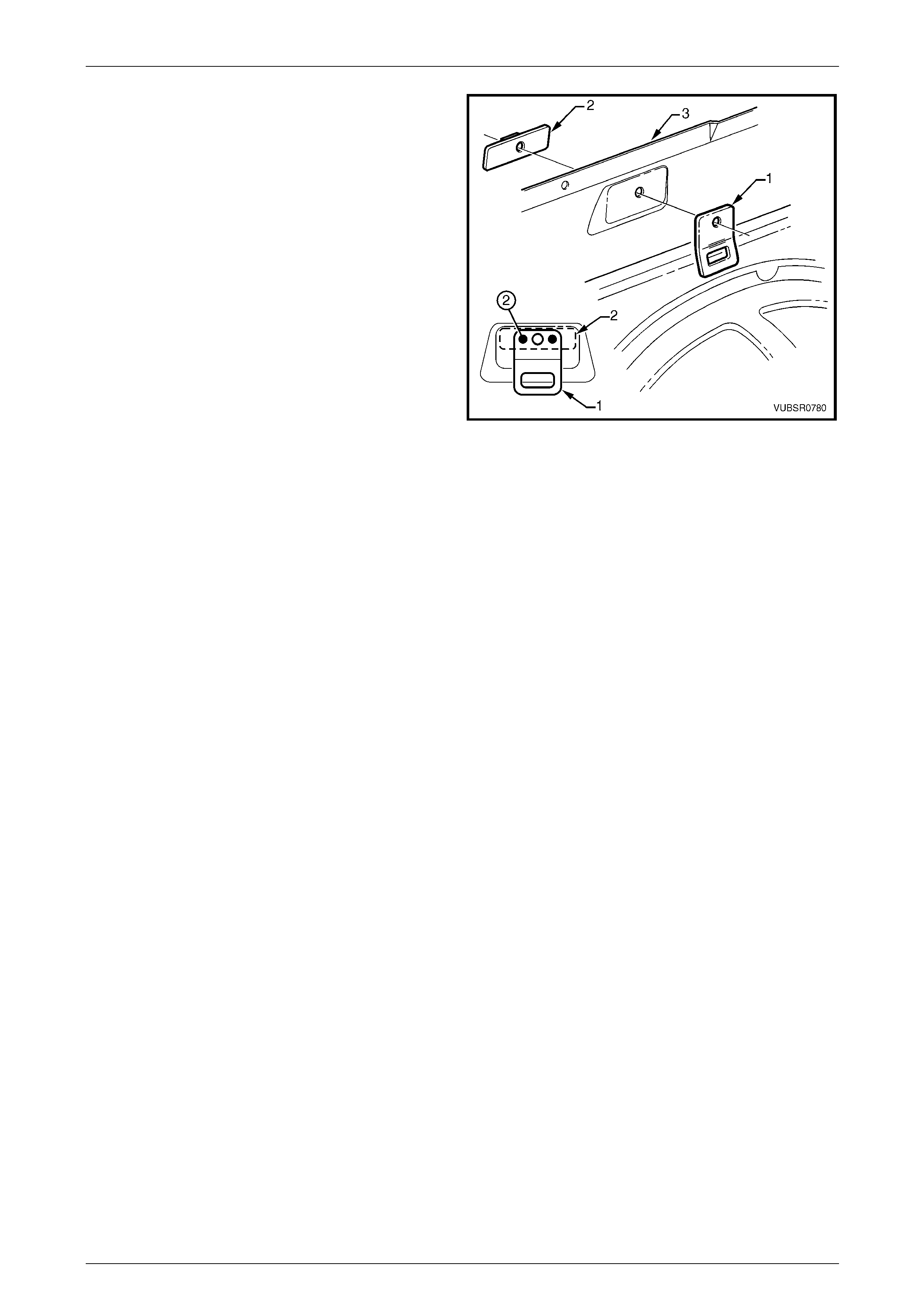
7C Body Side – Utility Page 7C-72
Page 7C-72
11 Clamp the cargo tie-down bracket (1) and the cargo
tie-down bracket anchor plate (2) to the side inner
upper panel (3).
12 Spot or plug the three parts, two places.
13 Repeat for each of the two other brackets.
14 Clean up and prime the areas that will be covered by
the quarter inner and rear wheelhouse brace.
15 Install the quarter inner and rear wheelhouse brace,
refer to 2.12 Quarter Inner and Rear Wheelhouse
Brace – Replace.
16 Clean up and prime areas that will be covered by the
following panels.
17 Install the door opening frame assembly, refer to
2.6 Door Opening Frame Assembly – Repl ace, or the
centre pillar and rocker sections.
18 Install the rear quarter panel,
refer to 2.1 Rear Quarter Panel – Replace.
19 Refinish and paint panels and other components as
required. Refer to Section 3 Body Construction .
Figure 7C – 140
20 Apply Joint Sealer (Item 3) as required. Refer to Section 3C Body Construction – Utility.
21 Apply Cavity Wax (Item 8) as required to the inside of any box secti ons or areas inaccessible to paint,
refer to Section 3C Body Construction – Utility.
22 Apply Spray-on Deadener (Item 7) to the wheel side of the rear wheelhouse as required,
refer to Section 3C Body Construction – Utility.
23 Install the remaining components as described in the appr opriate Section of the MY2005 VZ Service Information.
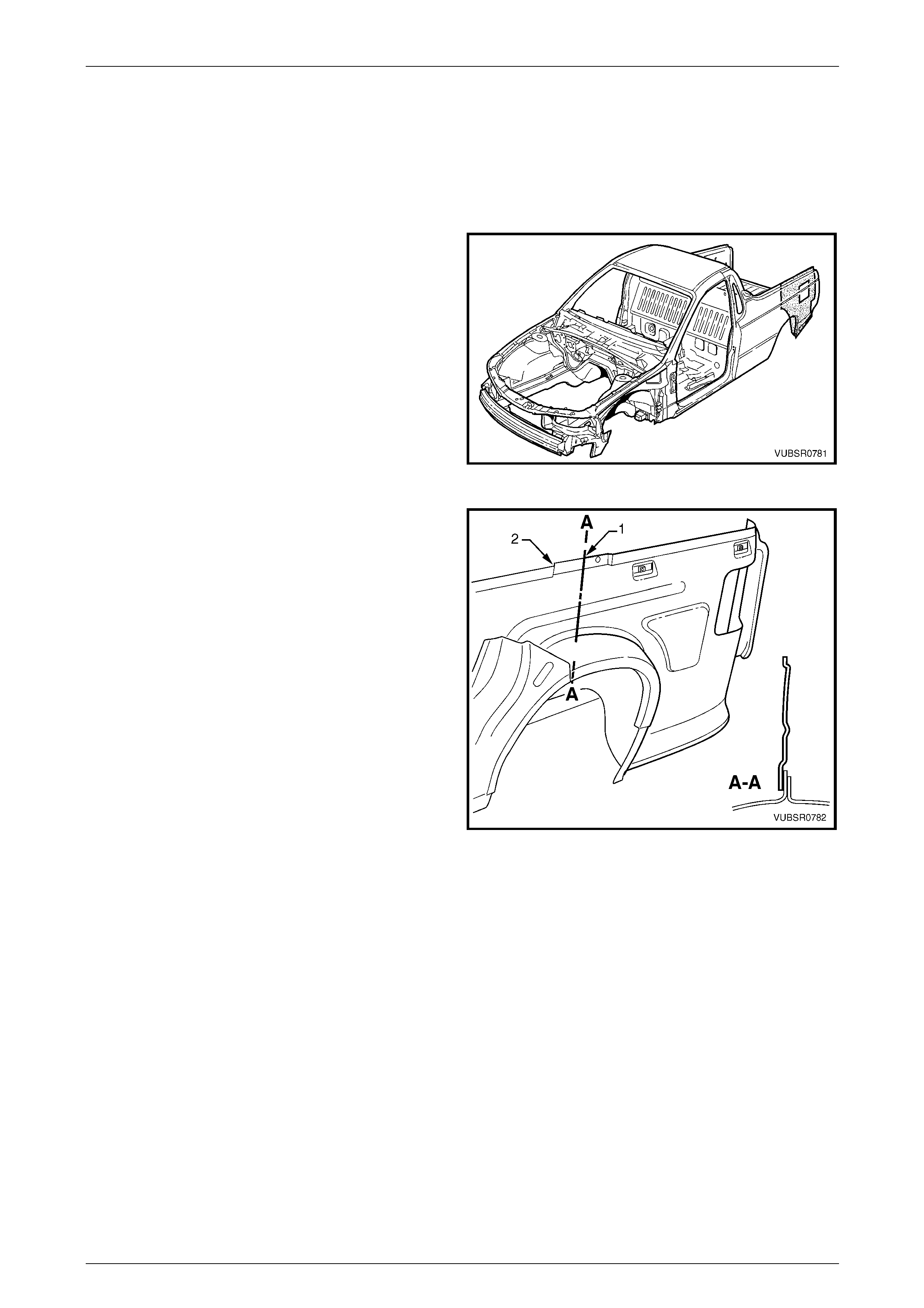
7C Body Side – Utility Page 7C-73
Page 7C-73
2.15 Side Inner Upper Panel – Partial Replace
The following procedure al lows partial replacement of a rear section of the side inner upper panel without the need to
replace the door opening fram e assembly.
Remove
1 Remove the adjacent bolt-on panels a nd components
as described in the appropriate Section of the MY2005
VZ Service Information.
2 Remove the rear quarter panel,
refer to 2.1 Rear Quarter Panel – Replace.
3 Remove the quarter outer lower rear panel, refer to
2.4 Quarter Outer Lower Rear Panel – Replace.
4 Remove the quarter inner lower rear extensi on,
refer to 2.3 Quarter Panel Inner Lower Rear
Extension – Replace.
5 Remove the quarter inner and rear wheelhouse brace,
refer to 2.12 Quarter Inner and Rear Wheelhouse
Brace – Replace. Figure 7C – 141
6 Cut through the side inner upper panel (1)
approximately central within the joggle (2) for the
quarter inner and rear wheelhouse brace.
7 Remove the welds attaching the rear section of the
side inner upper panel by referring to
2.14 Side Inner Upper Panel – Replace.
8 Remove the partial panel and repair any damage to
the surrounding area as required.
Figure 7C – 142
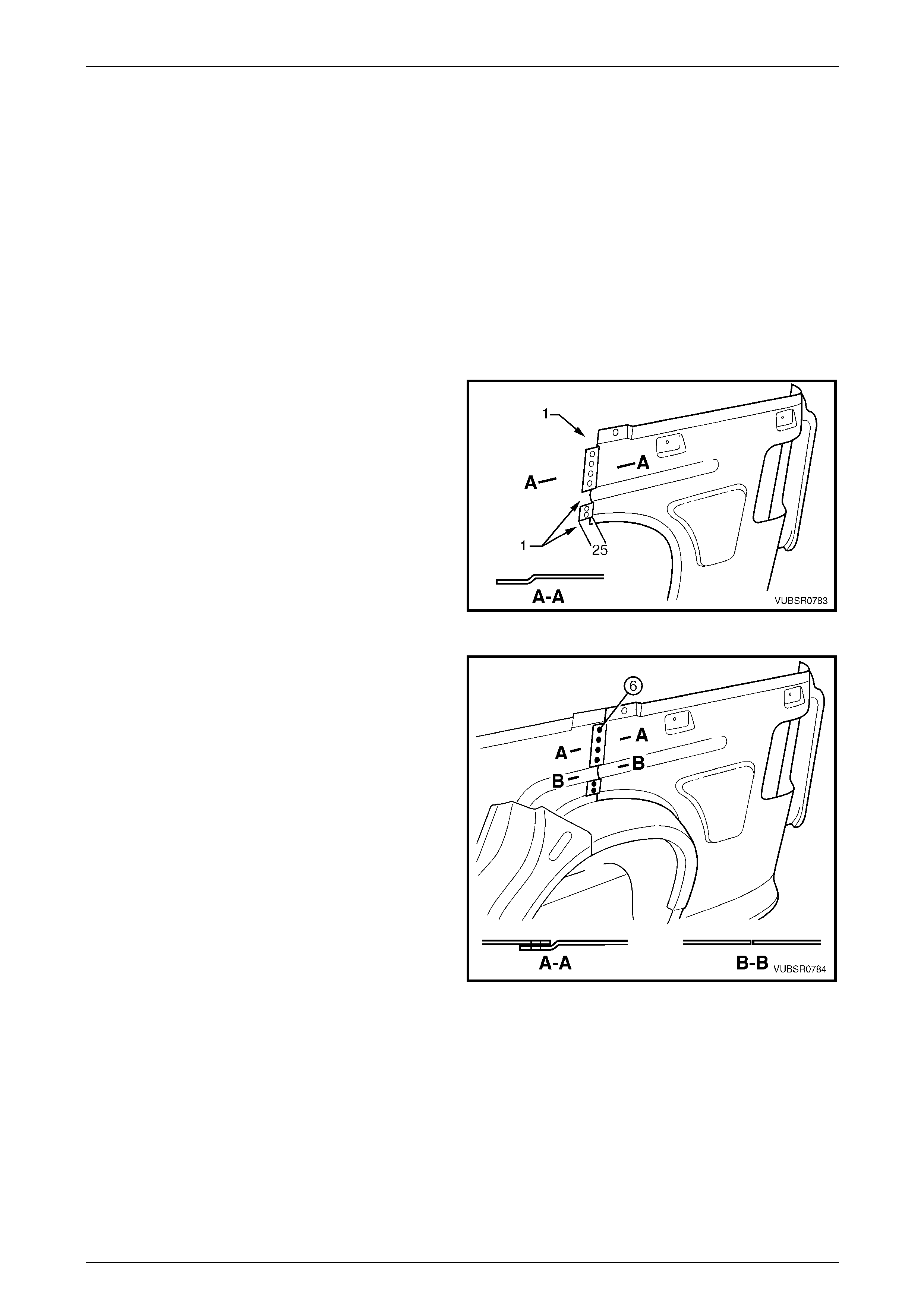
7C Body Side – Utility Page 7C-74
Page 7C-74
Replace
NOTE
• Spot welding is the preferred method for
attaching of panels and should be used
whenever possible. Where the spot welding
equipment available will not access the
required weld position, a plug weld should be
performed.
• The same number and position of spot welds
(or plug welds) should be used when
replacing the panel, as was used during
manufacture, in order to maintain the original
structural strength of the vehicle.
1 Accurately measure and cut the replacement side
inner upper panel section from a new panel. Allow a
further 25mm for a joggle.
2 Remove the areas (1) and joggle the remaining area
towards the outer side of the vehicle.
3 Mark the new panel and the jogg le with drilling
locations in preparation for plug welding as required.
Mark the holes at a maximum spacing of 35 mm. Drill
holes as marked.
4 Prepare all mating surfaces and treat with Weld
Through Primer (Item 1) as required,
refer to Section 3C Body Construction – Utility.
Figure 7C – 143
5 Fit and clamp the replacement section in position on
the vehicle ensuring the jo ggle is located on the outer
side of the side inner upper panel and the notched out
areas butt to the original section.
6 Spot or plug weld the replacement section al ong the
joggle.
7 Weld the replacement section to the vehicle using the
appropriate procedur es in 2.13 Quarter Panel Inner
Assembly – Replace.
Figure 7C – 144
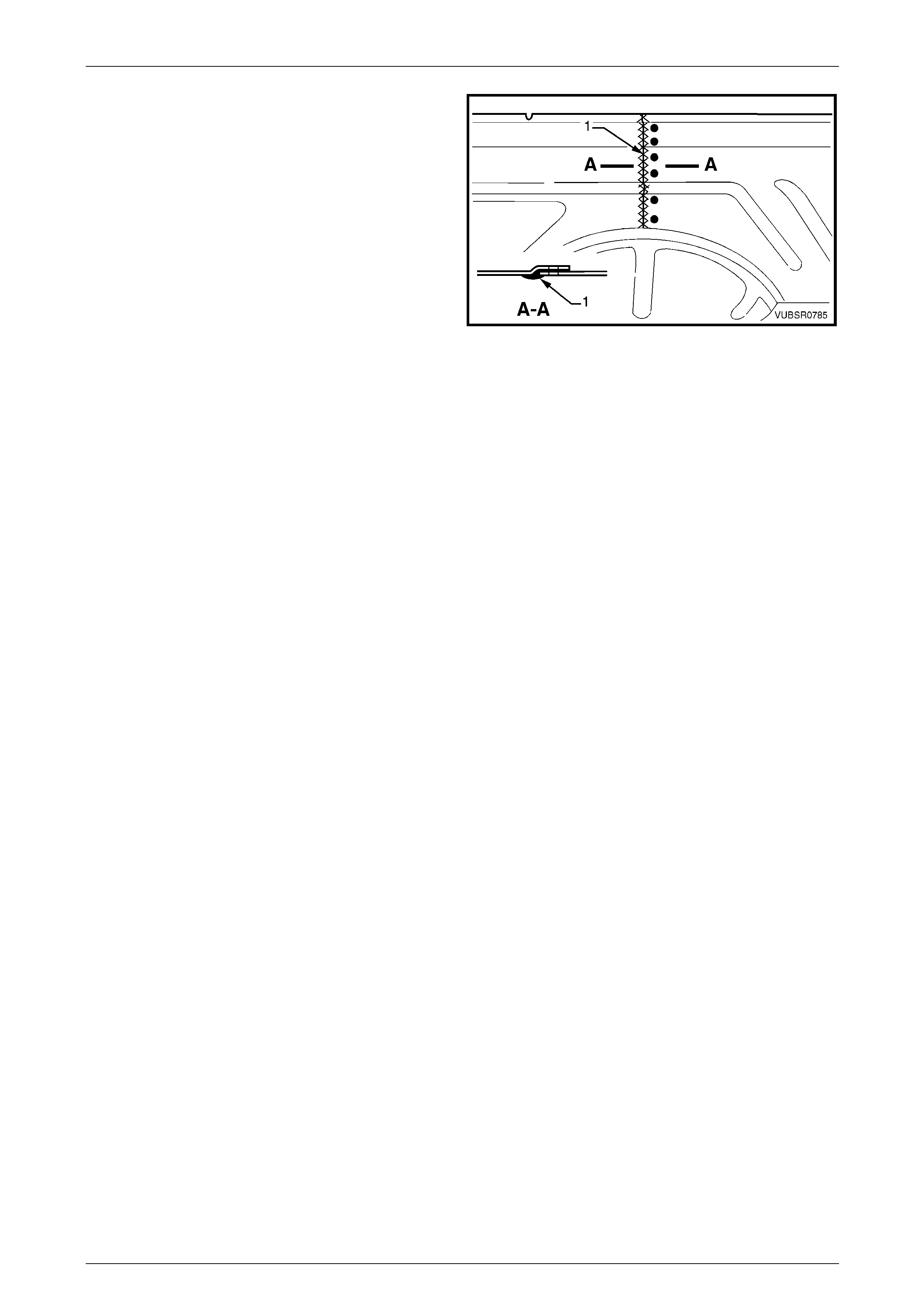
7C Body Side – Utility Page 7C-75
Page 7C-75
8 Complete the joint by MIG welding (1) on the inner
side of the side inner upper panel.
9 Grind the weld to achieve a sm ooth finish. Do not
remove the surrounding metal. F inish as req uired.
10 Clean up and prime areas that will be covered by the
quarter inner and rear wheelhouse brace.
11 Install the quarter inner and rear wheelhouse brace,
refer to 2.12 Quarter Inner and Rear Wheelhouse
Brace – Replace
12 Install the quarter inner lower rear extension, refer to
2.3 Quarter Panel Inner Lower Rear Extension –
Replace.
13 Install the cargo tie-down bracket (1) and cargo tie-
down bracket anchor plate as required, refer to
2.14 Side Inner Upper Panel – Replace.
Figure 7C – 145
14 Clean up and prime areas that will be covered by the rear quarter panel.
15 Install the rear quarter panel, refer to 2.1 Rear Quarter Panel – Replac e.
16 Refinish and paint panels and other components as required. Refer to Section 3 Body Construction.
17 Apply Joint Sealer (Item 3) as required. Refer to Section 3C Body Construction – Utility.
18 Apply Cavity Wax (Item 8) as required to the inside of any box secti ons or areas inaccessible to paint,
refer to Section 3C Body Construction – Utility.
19 Apply Spray-on Deadener (Item 7) to the wheel side of the rear wheelhouse as required,
refer to Section 3C Body Construction – Utility.
20 Install the remaining compon ents, refer to the appropriate Section of the MY2005 VZ Service Information.
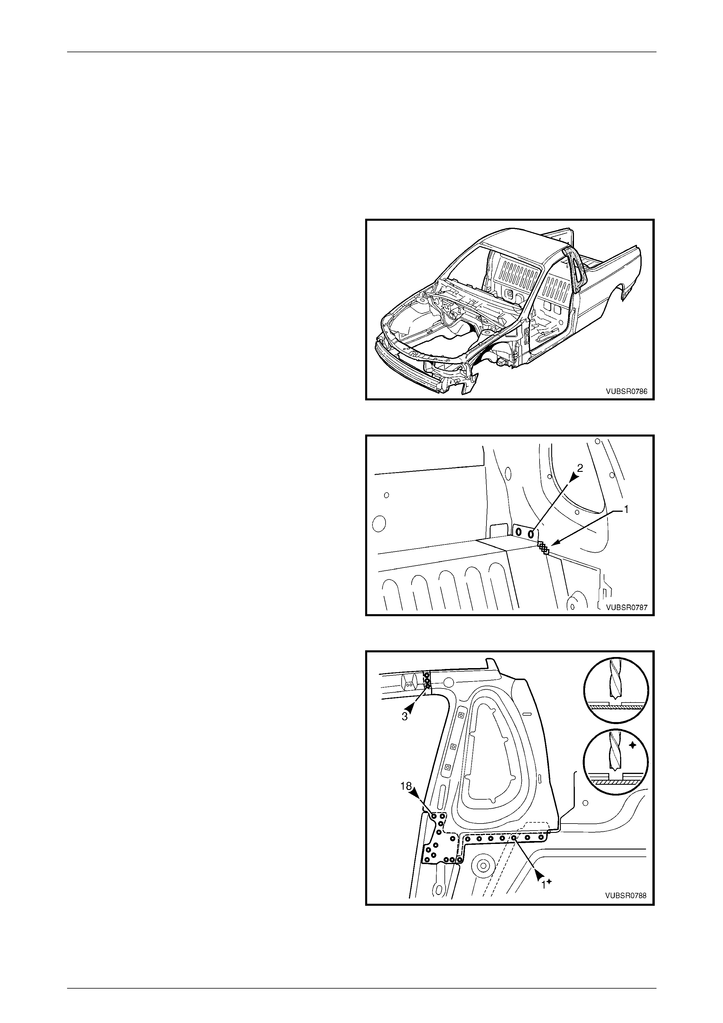
7C Body Side – Utility Page 7C-76
Page 7C-76
2.16 Side Inner Upper Front Panel – Replace
NOTE
This procedure includes the seatbelt guide
anchor plate assembly.
Remove
1 Remove the adjacent bolt-on panels a nd components
as described in the appropriate Section of the MY2005
VZ Service Information.
2 Mount the vehicle on a suitable jig to mai ntai n correct
body alignment when the panels are removed.
3 Remove the roof panel, refer to Section 9C Roof.
4 Remove the rear quarter panel,
refer to 2.1 Rear Quarter Panel – Replace.
5 Remove the door opening frame assembly, refer to
2.6 Door Opening Frame Assembly – Repl ace.
Figure 7C – 146
6 Spot cut the welds and grind off the MIG weld (1)
attaching the side inner upper front panel to the front
seatback panel outer.
Figure 7C – 147
7 Spot cut the welds attaching the side inner upper front
panel to the:
• Quarter panel inner extension roof three places,
• Quarter panel inner assembly and side inner
upper panel 17 places,
• Front seatback panel outer an d side inner upper
panel one plac e.
8 As required, remove any rem aining welds attaching
the side inner upper front panel that may not have
been completely cut through during removal of
adjacent panels.
9 Remove the side inner upper front panel and repair
any damage to the surroundi ng areas as required.
Figure 7C – 148
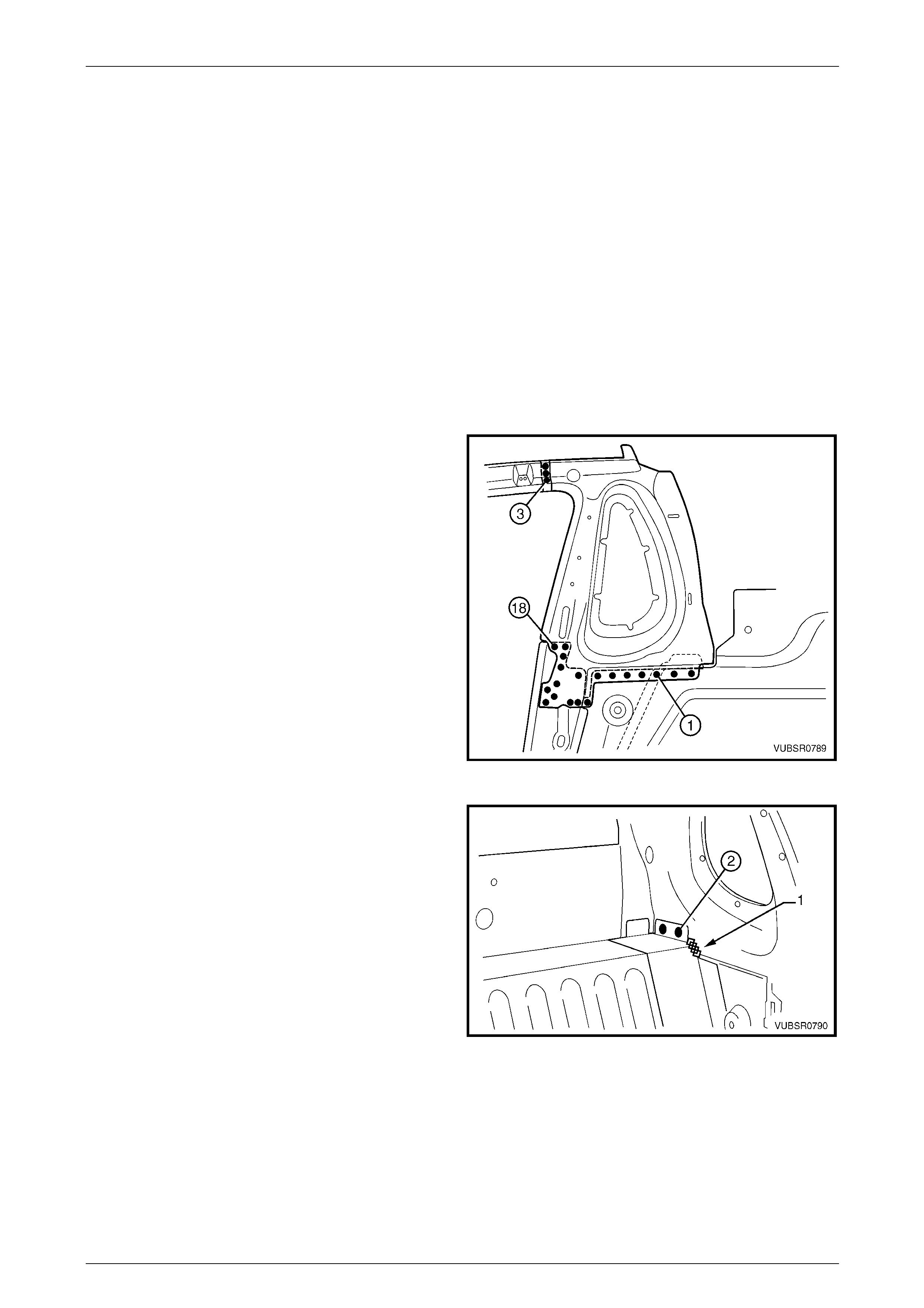
7C Body Side – Utility Page 7C-77
Page 7C-77
Replace
NOTE
• Spot welding is the preferred method for
attaching of panels and should be used
whenever possible. Where the spot welding
equipment available will not access the
required weld position, a plug weld should be
performed.
• The same number and position of spot welds
(or plug welds) should be used when
replacing the panel, as was used during
manufacture, in order to maintain the original
structural strength of the vehicle.
1 Mark the new panel and drill holes in preparation for plug welding where required.
2 Prepare all mating surfaces and treat with Weld Through Primer (Item 1) as required,
refer to Section 3C Body Construction – Utility.
3 Spot or plug weld the side inner upper front pan el to
the:
• Quarter panel inner extension three places,
• Quarter panel inner assembly and side inner
upper panel 17 places,
• Front seatback panel outer an d side inner upper
panel one plac e.
Figure 7C – 149
4 Spot or plug weld the front seatback panel outer to the
side inner upper front panel.
5 MIG weld (1) 25 mm the front seatback panel outer to
the side inner upper front panel.
Figure 7C – 150
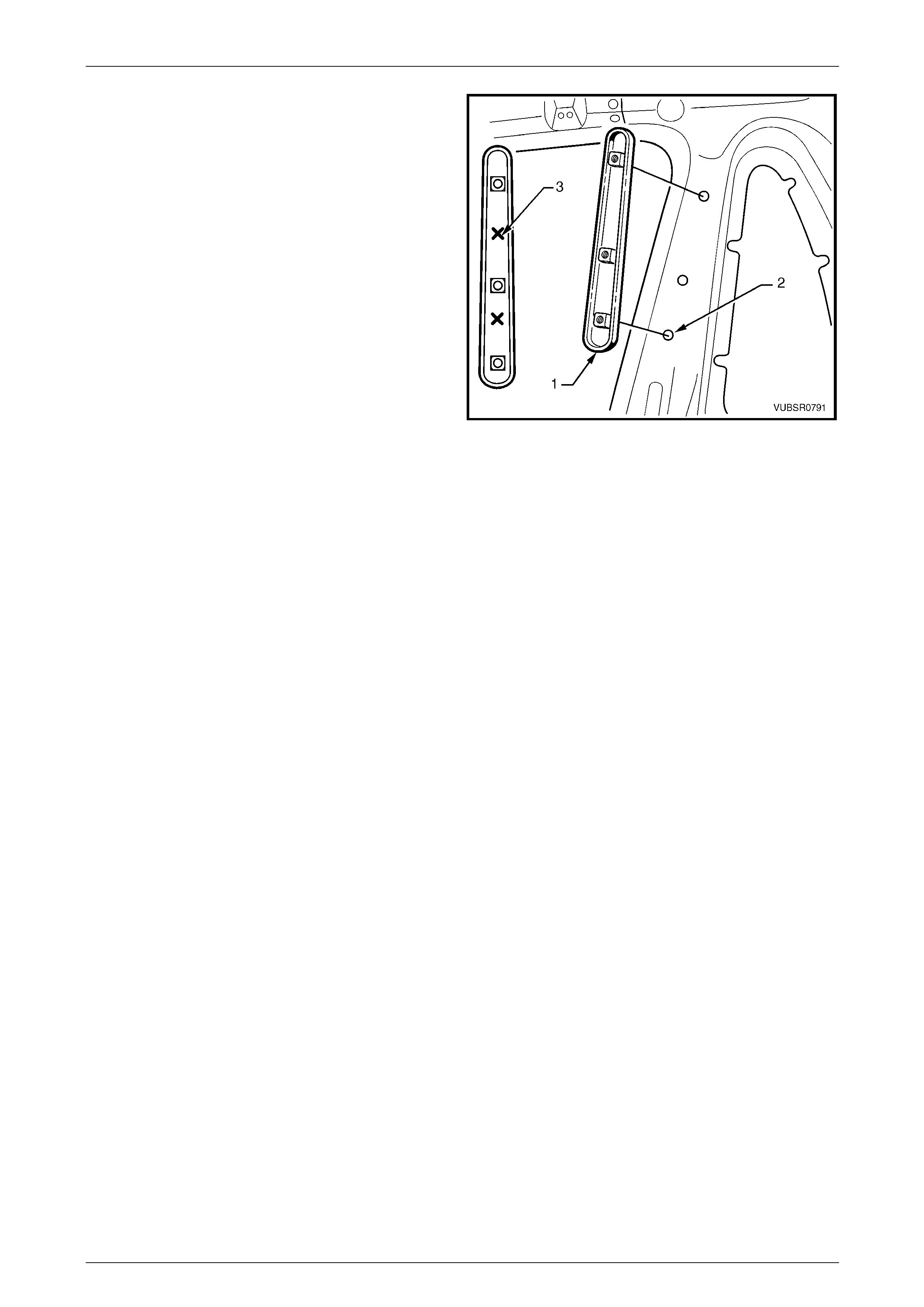
7C Body Side – Utility Page 7C-78
Page 7C-78
6 Locate the seatbelt guide anchor plate assembly (1)
over the seatbelt mounting bolt holes (2) as shown.
7 Spot or plug weld the seatbelt guide anchor plate
assembly to the side inner upper front panel, two
places (3).
8 Clean up and prime areas that will be covered by the
following panels.
9 Install the door opening frame assembly refer to
2.6 Door Opening Frame Assembly – Repl ace.
10 Install the roof panel, refer to Section 9 Roof
11 Install the rear quarter panel,
refer to 2.1 Rear Quarter Panel – Replace.
12 Refinish and paint panels and other components as
required. Refer to Section 3 Body Construction .
13 Apply Joint Sealer (Item 3) as required.
Refer to Section 3C Body Construction – Utility.
14 Apply Cavity Wax (Item 8) as required to the inside of
any box sections or areas inaccessible to paint,
refer to Section 3C Body Construction – Utility.
Figure 7C – 151
15 Install the remaining components as described in the appr opriate Section of the MY2005 VZ Service Information.
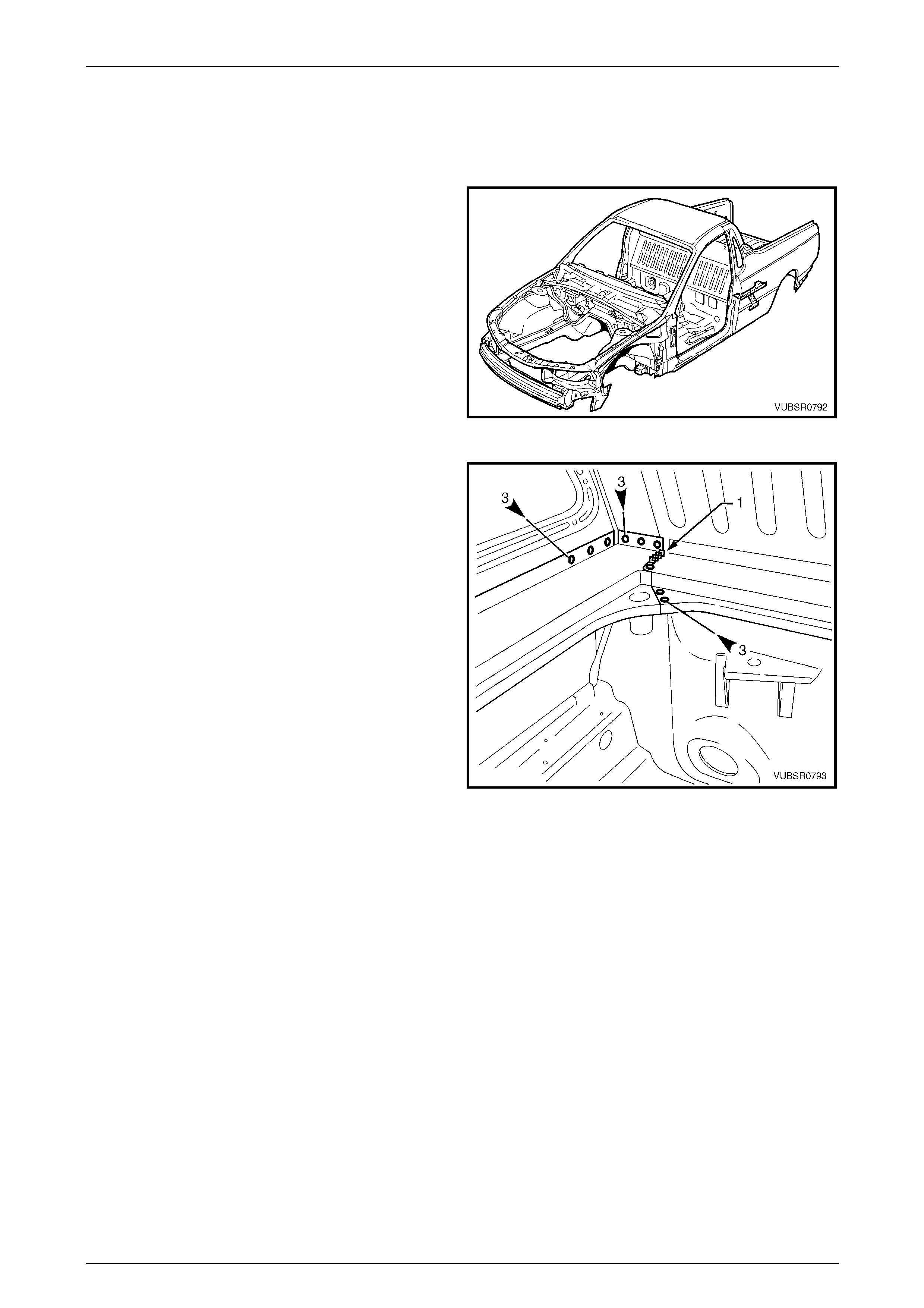
7C Body Side – Utility Page 7C-79
Page 7C-79
2.17 Load Floor Panel Outer Extension and
Load Floor Panel Outer Reinforcement –
Replace
1 Remove the adjacent bolt-on panels a nd components
as described in the appropriate Section of the MY2005
VZ Service Information.
2 Remove the adjacent panels as required, refer to the
relevant Section in this Supplement.
Figure 7C – 152
3 Spot cut the welds attaching the load floor panel outer
extension to the side inner upper panel three places,
the front seatback panel outer three places and the
front seatback panel three places.
4 Grind off the MIG weld (1) attaching the load floor
panel outer extension to the front seatback panel.
Figure 7C – 153
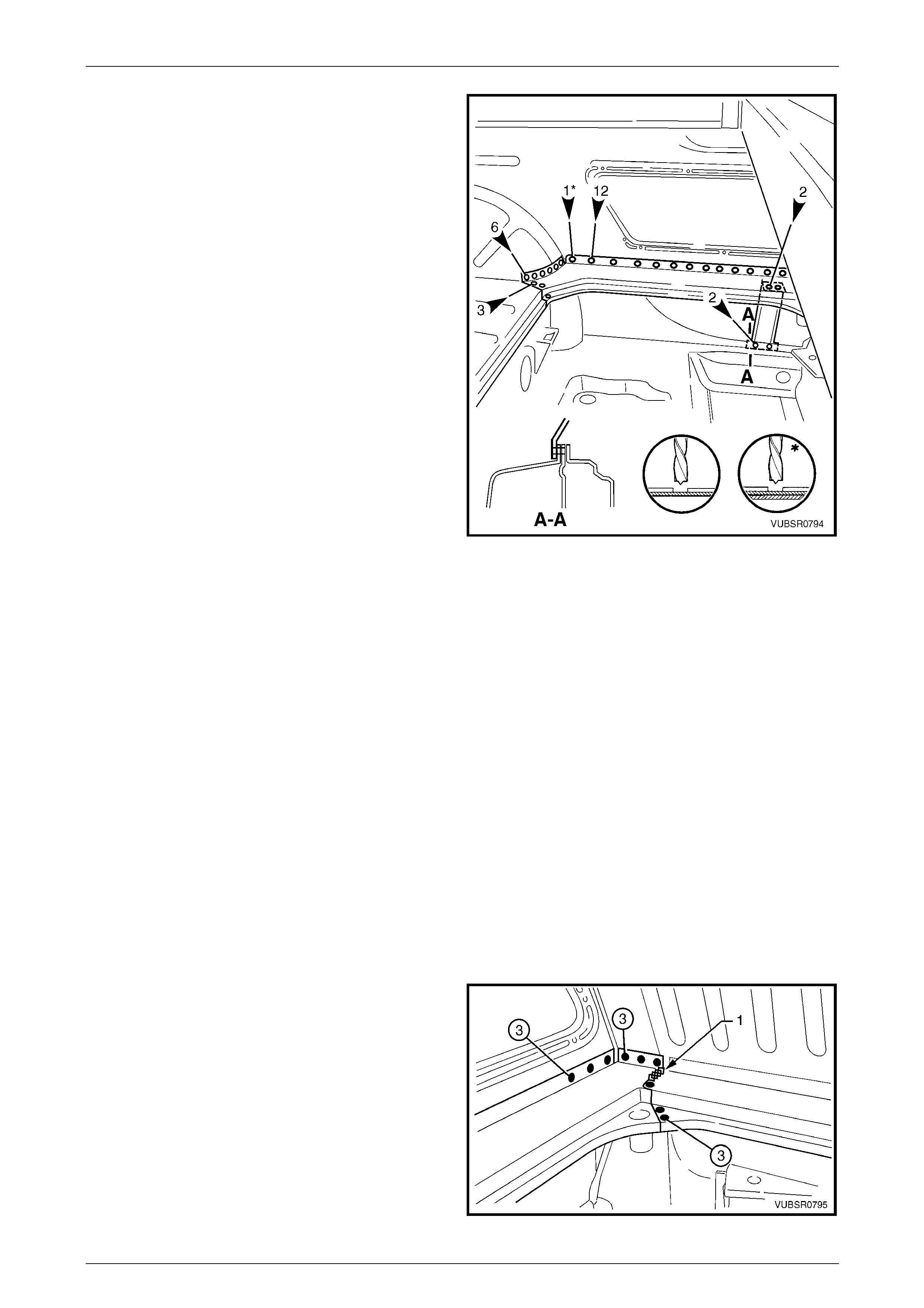
7C Body Side – Utility Page 7C-80
Page 7C-80
5 Spot cut the welds attaching the load floor panel outer
extension to the load floor p anel outer reinforcement
two places.
6 Spot cut the welds attaching the load floor panel outer
extension to the side inner upper panel t welve places,
the rear wheelhouse inner panel and side inner up per
panel one place, the rear wheelhouse inner panel six
places and the load floor panel three places.
7 Remove the load floor panel outer extension from the
vehicle.
8 If required, spot cut the welds attaching the load floor
panel outer reinforcement to the door opening frame
assembly two places and remove the rei nforceme nt.
NOTE
The spot welds are not visible from the inside of
the vehicle. If the rear quarter panel is not
removed cut the welds with a saw or chisel.
Figure 7C – 154
Replace
NOTE
• Spot welding is the preferred method for
attaching of panels and should be used
whenever possible. Where the spot welding
equipment available will not access the
required weld position, a plug weld should be
performed.
• The same number and position of spot welds
(or plug welds) should be used when
replacing the panel, as was used during
manufacture, in order to maintain the original
structural strength of the vehicle.
1 Mark the new panel and drill holes in preparation for plug welding where required.
2 Prepare all mating surfaces and treat with Weld Through Primer (Item 1) as required,
refer to Section 3C Body Construction – Utility.
3 Apply Structural Adhesive (Item 6) to the load floor p an el mating surface (1, refer to Figure 7C – 156),
refer to Section 3C Body Construction – Utility.
4 Clamp the load floor panel outer extension in position
and spot or plug weld to the front seatback panel outer
three places and the front seatback panel three
places.
5 MIG weld (1) 25 mm the to the front seatback panel.
6 Spot or plug weld side the load floor pane l outer
extension to the side inner upper panel three places.
Figure 7C – 155
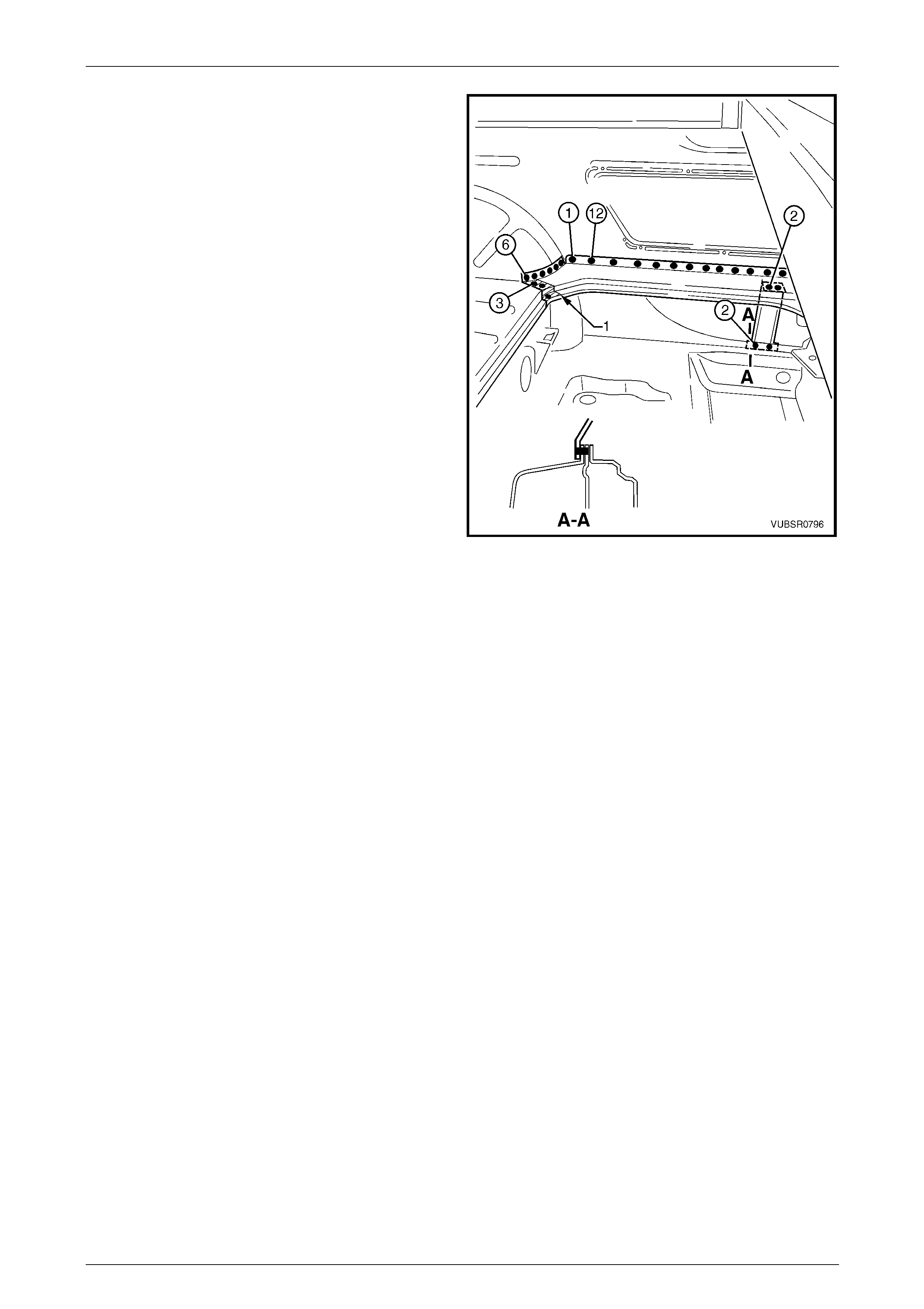
7C Body Side – Utility Page 7C-81
Page 7C-81
7 Spot or plug weld the load floor panel outer extension
to the side inner upper panel twelve plac es.
8 Spot or plug weld the extension to the rear
wheelhouse inner panel and side inner u pper panel
one place.
9 Spot or plug weld the extension to the rear
wheelhouse inner panel six places an d the load floor
panel three places.
10 If removed, spot or plug weld the load floor panel outer
reinforcement to the lower flange two places.
NOTE
If the rear quarter panel was not removed, drill
through the flange from the inside and plug weld
through the flange.
11 Spot or plug weld the reinforcement to the extensio n
two places.
12 Install any other removed pan els as req uire d, refer to
the appropriate Section of this Supplement.
13 Refinish and paint panels and other components as
required. Refer to Section 3 Body Construction .
14 Apply Joint Sealer (Item 3) as required.
Refer to Section 3C Body Construction – Utility.
15 Apply Cavity Wax (Item 8) as required to the inside of
any box sections or areas inaccessible to paint,
refer to Section 3C Body Construction – Utility.
16 Install the remaining components as described in the
appropriate Section of the MY2005 VZ Service
Information.
Figure 7C – 156

7C Body Side – Utility Page 7C-82
Page 7C-82
2.18 Rear Wheelhouse Inner Panel – Replace
Remove
1 Remove the adjacent bolt-on panels a nd components
as described in the appropriate Section of the MY2005
VZ Service Information.
2 Remove the adjacent panels as required, refer to the
relevant Section in this Supplement.
Figure 7C – 157
3 Grind off the MIG welds (1) attaching the rear floor
panel assembly to the rear wheelhouse inner panel.
4 Spot cut the welds attaching the rear wheelhouse
inner panel to the quarter panel in ner assembly and
side inner upper panel six places.
5 Spot cut the weld attaching the load floor outer
extension to the rear wheelhouse inner panel and side
inner upper panel one place.
6 Spot cut the welds attaching the load floor outer
extension to the rear wheelhouse inner panel six
places.
7 Spot cut the welds attaching the load floor panel to the
rear wheelhouse inner panel five places.
8 Grind off the MIG weld (1) attaching the load floor
panel to the rear wheelhouse inner panel and side
inner upper panel, refer to Figure 7C – 159.
9 For the left-hand side, spot cut the welds attaching
rear wheelhouse inner panel to the side inner upper
panel and quarter pane l inner assembly, 18 places,
refer to Figure 7C – 159.
10 For the right-hand side, spot cut the welds attaching
rear wheelhouse inner panel to the side inner upper
panel and quarter pane l inner assembly, 12 places
and the side inner upper panel and rear wheelhouse
outer extension 12 places, refer to Figure 7C – 159.
Figure 7C – 158

7C Body Side – Utility Page 7C-83
Page 7C-83
Figure 7C – 159
11 Spot cut the welds attaching the rear wheelhouse
inner panel to the load floor panel, five places on the
left-hand side or 10 places on the right-hand side.
12 As required, spot cut the welds attaching the rear
wheelhouse bracket to the rear wheelhouse inner
panel and quarter pane l inner assembly.
13 If the rear quarter panel and door op ening frame
assembly have been removed, spot cut the three
welds (1) attaching the quarter panel inn er a ssembly
to the wheelhouse inner, refer to Figure 7C – 161.
NOTE
If the panels have not been removed, cut along
the line (2) and across th e flan ge on the i nsid e of
the vehicle to detach this piece.
14 Spot cut the welds attaching the quarter panel inner
assembly and door opening frame assembly to the
rear wheelhouse inner panel, two places,
refer to Figure 7C – 161.
15 Spot cut the welds attaching the rear wheelhouse
inner panel to the inner rocker panel, three places,
refer to Figure 7C – 161.
Figure 7C – 160
16 Spot cut the welds attaching the rear wheelhouse inn er panel to the load floor panel and rear floor panel assembl y,
23 places, refer to Figure 7C – 161.
17 Remove the rear wheelhouse inner panel and repair any damage to the surrounding are as as required.
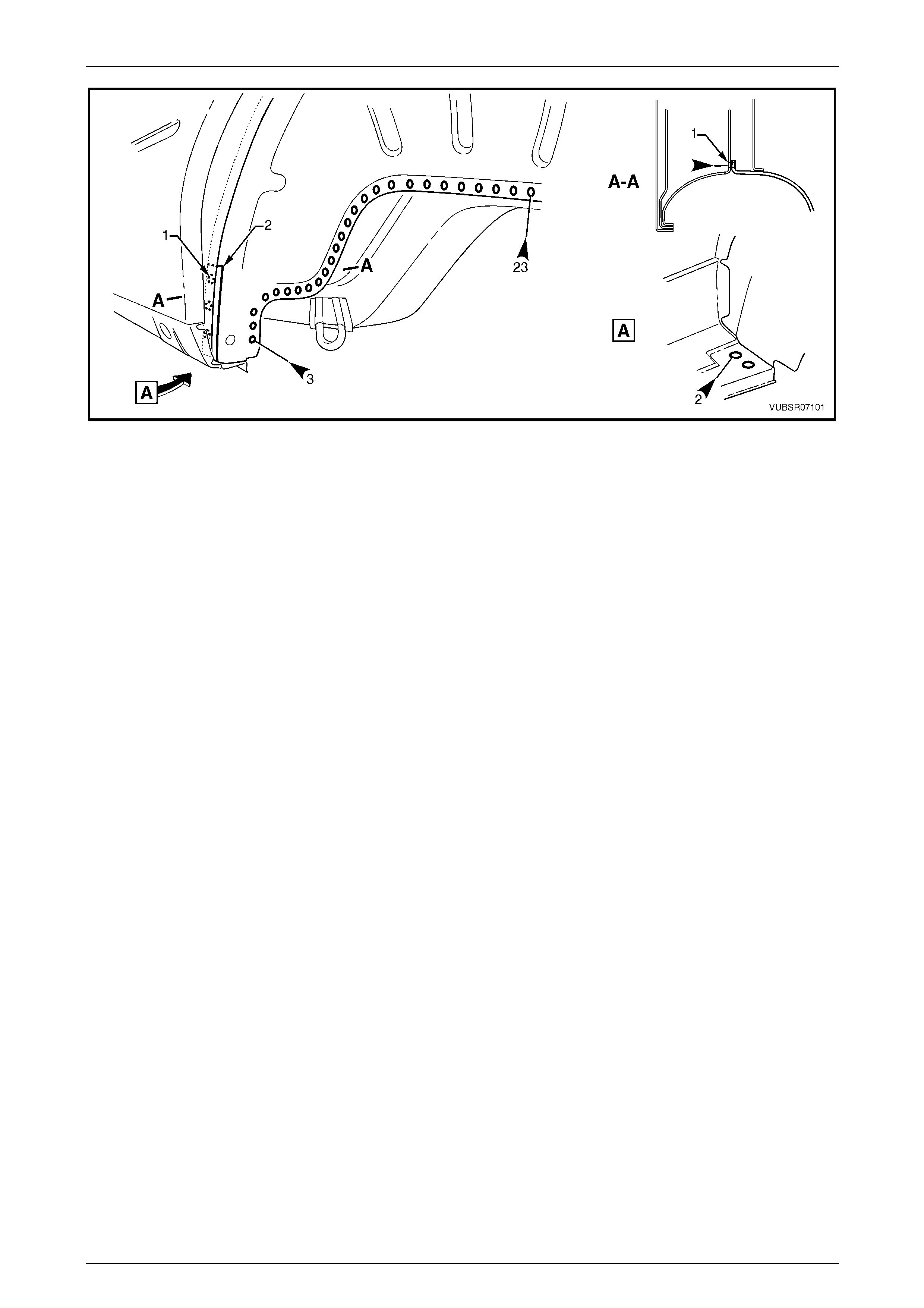
7C Body Side – Utility Page 7C-84
Page 7C-84
Figure 7C – 161
Replace
NOTE
• Spot welding is the preferred method for
attaching of panels and should be used
whenever possible. Where the spot welding
equipment available will not access the
required weld position, a plug weld should be
performed.
• The same number and position of spot welds
(or plug welds) should be used when
replacing the panel, as was used during
manufacture, in order to maintain the original
structural strength of the vehicle.
1 Mark the new panel and drill holes in preparation for plug welding where required.
2 Prepare all mating surfaces and treat with Weld Through Primer (Item 1) as required,
refer to Section 3C Body Construction – Utility.
3 If the front piece of the rear wheelhouse was cut off, remove a corresponding piece from the replacement panel.
4 Apply Structural Adhesive (Item 6) to the rear wheelhouse inner panel (3, refer to Figure 7C – 16 4),
refer to Section 3C Body Construction – Utility.
5 Clamp the rear wheelhouse inner panel in position on the vehicle.
6 For the left-hand side, spot or plug weld the rear wheelhouse inner panel to the quarter panel inner assembly and
side inner upper panel, 18 pl aces, refer to F igure 7C – 162.
7 For the right-hand side, spot or plug weld the rear wheelhouse inner panel to the quarter panel inner assembly and
side inner upper panel, 12 pl aces and the side inner upper panel and rear wheelhouse outer extension 12 places,
refer to Figure 7C – 162.
8 MIG weld 25 - 50 mm (1) the load floor panel to the rear wheelhouse inner pane l and side inner upper panel,
refer to Figure 7C – 162.
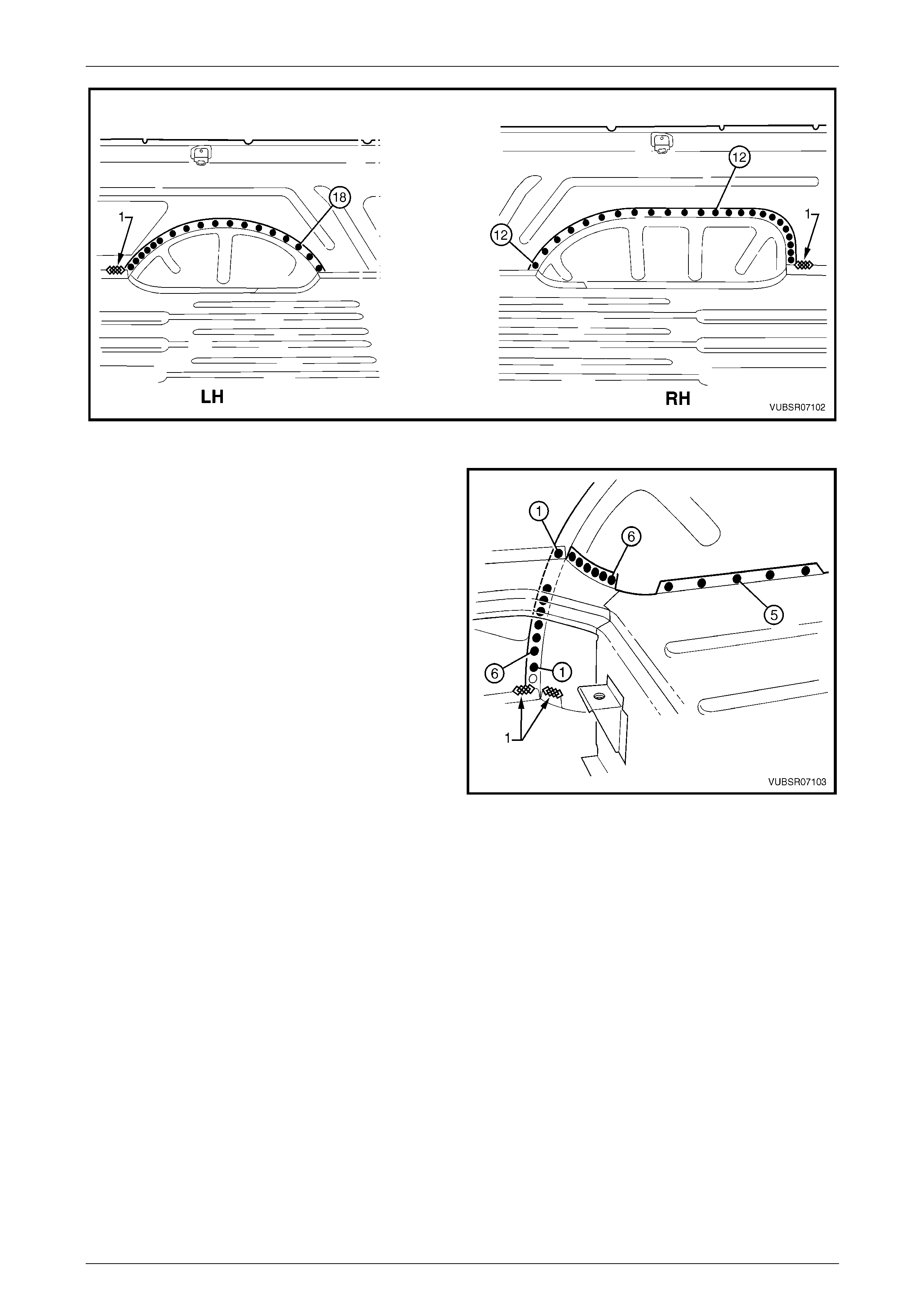
7C Body Side – Utility Page 7C-85
Page 7C-85
Figure 7C – 162
9 Spot or plug weld the load floor panel to the rear
wheelhouse inner panel five places.
10 Spot or plug weld the load floor outer extension to the
rear wheelhouse inner panel six places.
11 Spot or plug weld the load floor outer extension to the
rear wheelhouse inner panel and side inner upper
panel one plac e.
12 Spot or plug weld the rear wheelhouse inner panel to
the side inner upper panel an d quarter panel inner
assembly six places.
13 MIG weld 25 mm (1) two places, the rear floor panel
assembly to the rear wheelhouse inner p anel.
Figure 7C – 163
14 If the rear quarter panel and door op ening frame assembly were removed, spot or plug weld (1) three places the
quarter panel inner assembly to the rear wheelhouse inner panel, refer to Figure 7 C – 164.
NOTE
If the panels were not removed, MIG weld along
the cut (2) and across the flange on the inside of
the vehicle.
15 Spot or plug weld the rear quarter panel and door open ing frame assembly to the rear wheelhouse inner panel, two
places, refer to Figure 7C – 164.
16 Spot or plug weld the rear wheelhouse inner panel to the inner rocker panel, three places, refer to Figure 7C – 164.
17 Spot or plug weld the rear wheelhouse inner panel to the load floor p an el and rear floor panel assembly, 23 places,
refer to Figure 7C – 164.
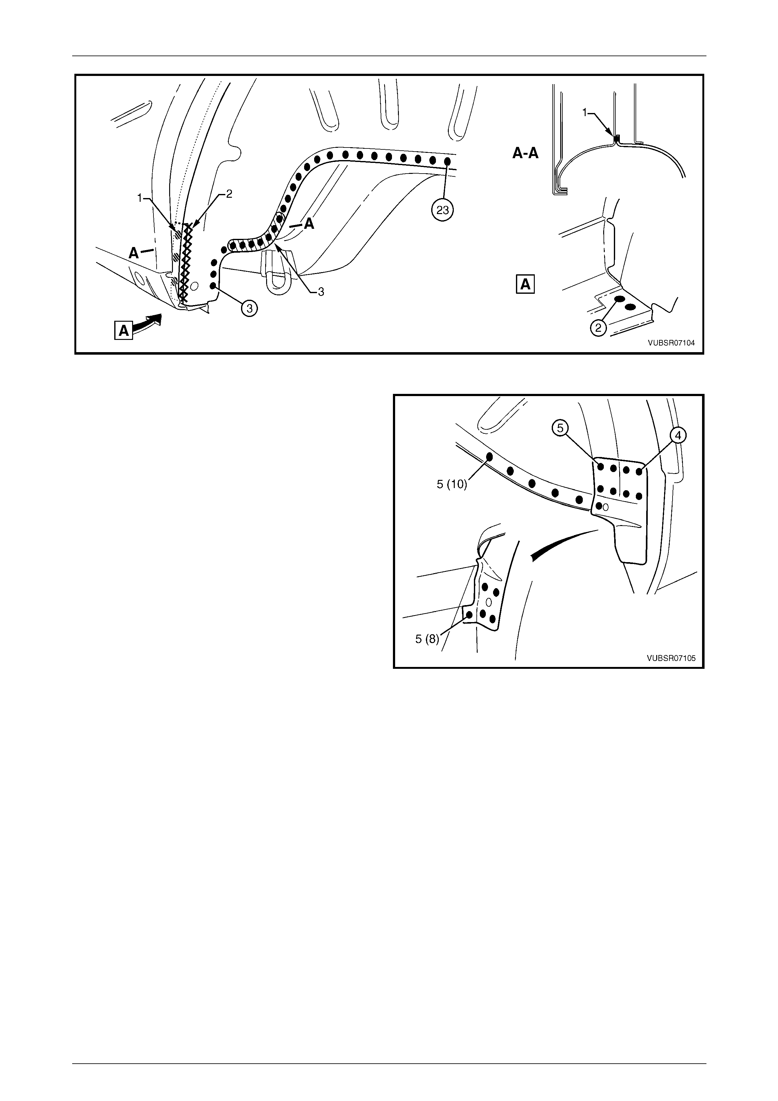
7C Body Side – Utility Page 7C-86
Page 7C-86
Figure 7C – 164
18 Spot or plug weld the rear wheelhouse inner panel to
the load floor panel, five places on the left-hand side
or 10 places on the right-hand side.
19 As required, spot or plug weld the rear wheelhouse
bracket to the rear wheelhouse inn er pa nel and
quarter panel inner assembly.
20 Install any other removed pan els as req uire d, refer to
the appropriate Section of this Supplement.
21 Refinish and paint panels and other components as
required. Refer to Section 3 Body Construction .
22 Apply Joint Sealer (Item 3) as required.
Refer to Section 3C Body Construction – Utility.
Figure 7C – 165
23 Apply Cavity Wax (Item 8) as required to the inside of any box secti ons or areas inaccessible to paint,
refer to Section 3C Body Construction – Utility.
24 Apply Spray-o n deadener to the wheel side of the rear wheelhouse panel,
refer to Section 3C Body Construction – Utility.
25 Install the remaining components as described in the appr opriate Section of the MY2005 VZ Service Information.

7C Body Side – Utility Page 7C-87
Page 7C-87
3 Torque Wrench Specifications
Dash Panel Retaining Bolt.........................................................35.0 – 45.0 Nm