
7F Body Side – Crew Cab Page 7F–1
Page 7F–1
Section 7F
Body Side – Crew Cab
ATTENTION
Before performing any service operation or other procedure described in this Section, refer to Section 2
Precautions in this Supplement and Section 00 Warnings, Cautions and Notes in the MY2005 VZ Service
Information for correct workshop practices with regard to safety and/or property damage.
The structure of the body shell has been
developed using complex design and
development techniques. In addition to
meeting all required standards, the vehicle
body is also a critical part of the overall safety
systems. It is therefore imperative the repair
procedures described here are adhered to
during all vehicle body repairs.
1 General Information ...............................................................................................................................2
1.1 Body Side Components ........................................................................................................................................ 2
2 Service Operations.................................................................................................................................4
2.1 Rear Quarter Panel – Replace............................................................................................................................... 4
Remove................................................................................................................................................................... 4
Replace................................................................................................................................................................... 5
2.2 Door Opening Frame Assembly – Replace.......................................................................................................... 6
Remove................................................................................................................................................................... 6
Replace................................................................................................................................................................. 10
2.3 Door Opening Frame Assembly – Partial Replace, Hinge Pillar...................................................................... 15
Remove................................................................................................................................................................. 15
Replace................................................................................................................................................................. 18
2.4 Door Opening Frame Assembly – Partial Replace, Centre Pillar..................................................................... 23
Remove................................................................................................................................................................. 23
Replace................................................................................................................................................................. 26
2.5 Door Opening Frame Assembly – Partial Replace, Lock Pillar........................................................................ 30
Remove................................................................................................................................................................. 30
Replace................................................................................................................................................................. 31
2.6 Door Opening Frame Assembly – Partial Replace, Rocker Panel................................................................... 33
Remove................................................................................................................................................................. 33
Replace................................................................................................................................................................. 35
2.7 Quarter Panel Inner Assembly – Replace.......................................................................................................... 39
Remove................................................................................................................................................................. 39
Replace................................................................................................................................................................. 41

7F Body Side – Crew Cab Page 7F–2
Page 7F–2
1 General Information
This Section describes the replacement procedures for the body side com ponents of the Crew Cab body structure.
Removal of bolt-on panels and mecha nica l components is not covered. For information on the removal of these parts,
reference must be made to the appropriate Section in the MY 2005 VZ Service Information.
With the following exceptions, Cre w Cab body side inform ation carries over from Utility body side,
refer to Section 7C Body Side – Utility.
• Body side components
• Rear quarter panel
• Door opening frame assembl y
• Quarter panel inner assembly
This Section includes door opening frame assembly partial r eplacement procedures for the hinge p illar, centre pillar and
rocker panel. These procedures must be followed carefully, as they can involve hidden reinforcement panels. The cutting
locations specified are the only places allowable.
NOTE
• When repairing the body side of the vehicle,
care must be taken to ensure the structure is
returned to its original production
configuration. This is especially important to
maintain side impact standards.
• It is imperative the correct body adhesives,
sealers, deadeners and cavity waxes are
used when repairing th e body structure. Refer
to Section 3F Body Construction – Crew Cab.
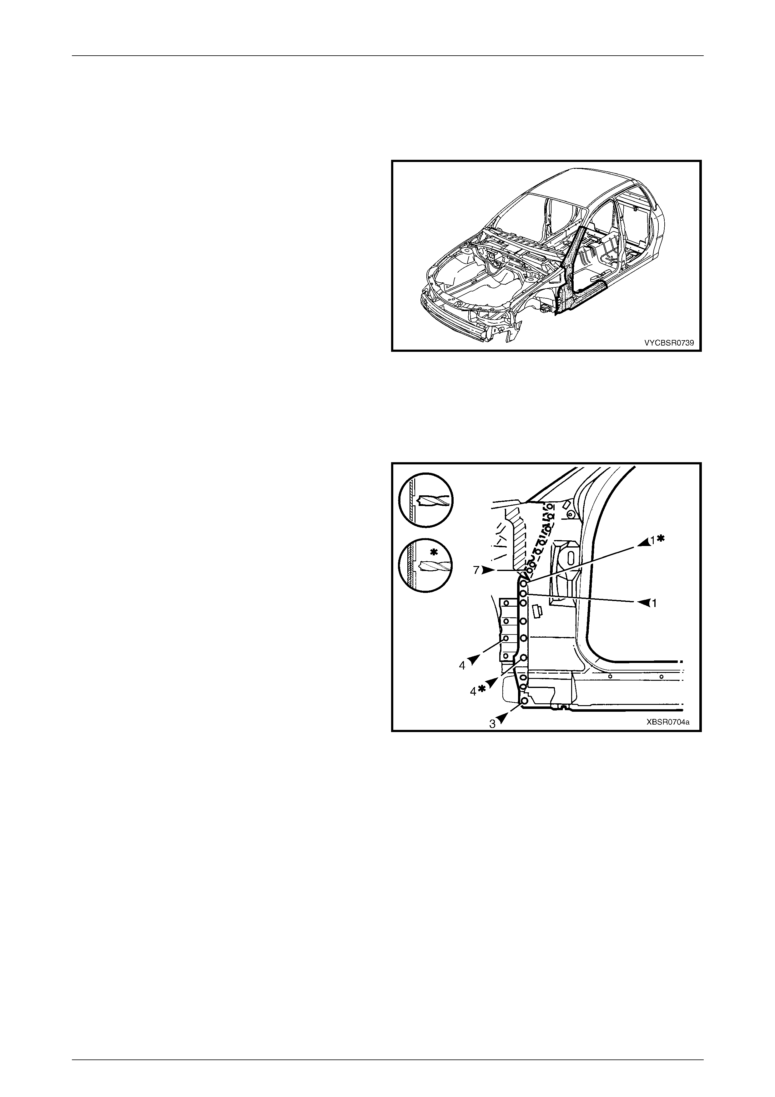
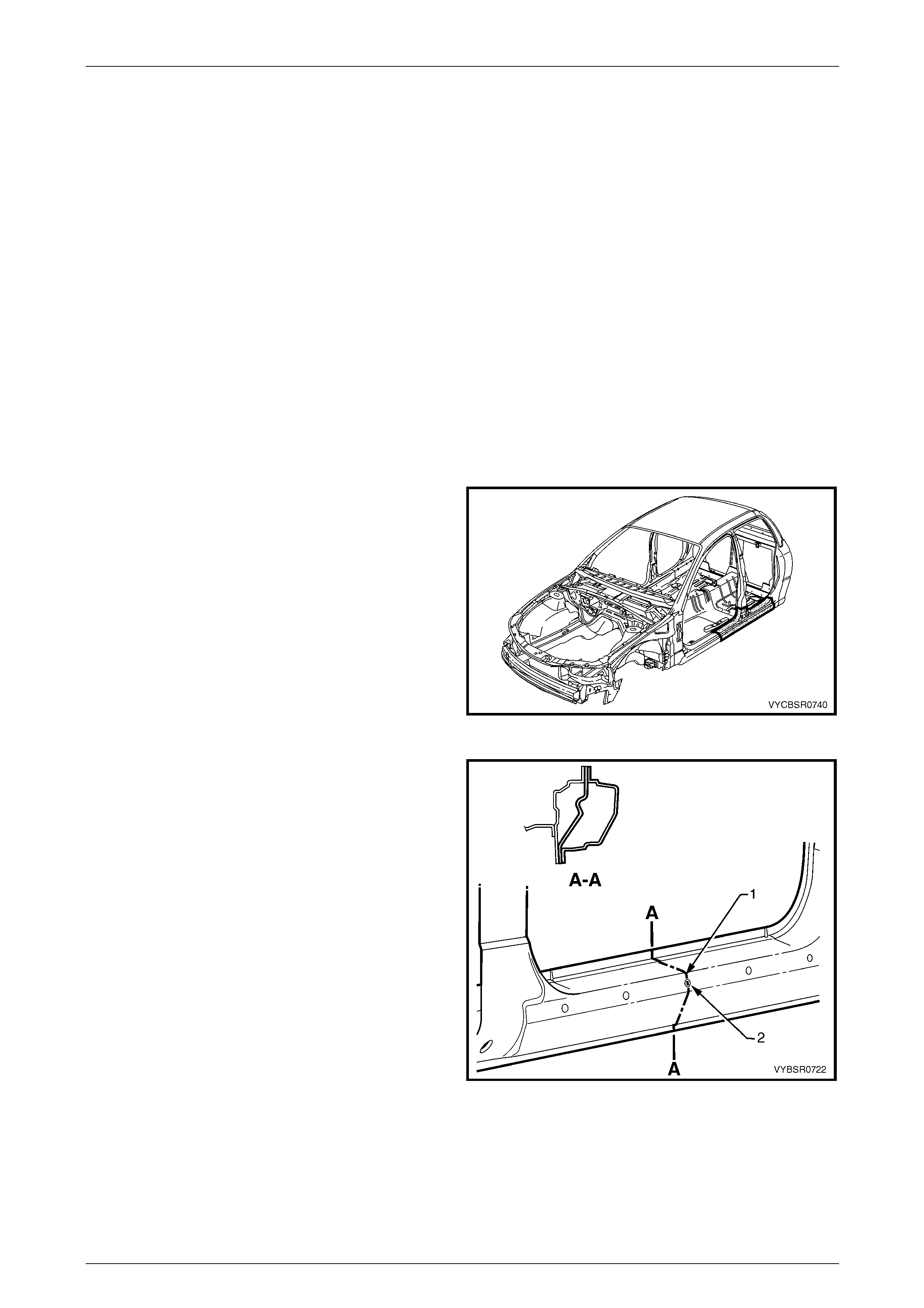
1.1 Body Side Components
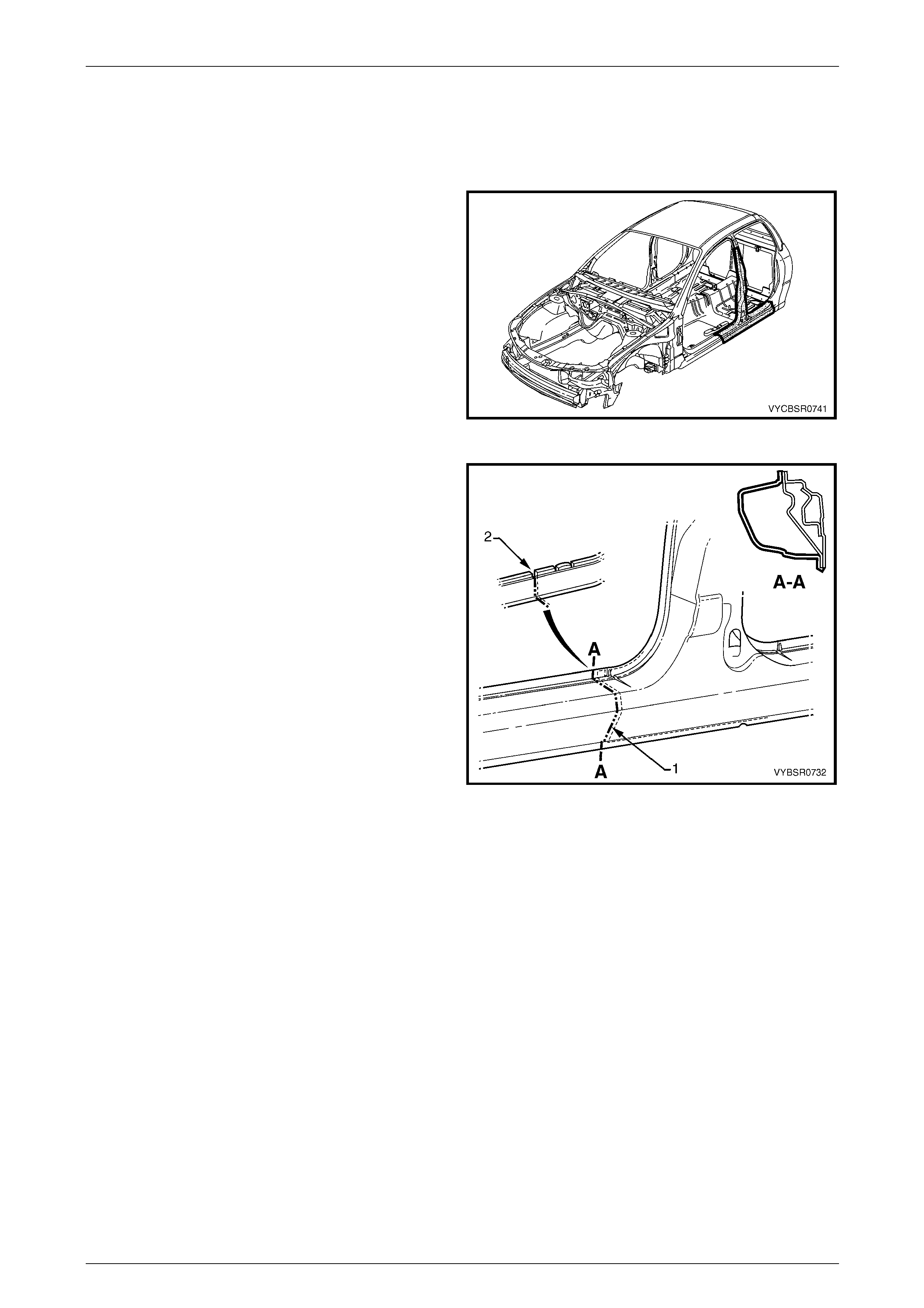
The shaded components shown are those dealt with in this
Section.
The components and assemblies shown in Figure 7F – 2
are the parts serviced for Crew Cab vehicles which
form the basis of the repair procedures in this Section. F or a
detailed view of the body components,
refer to Section 3F Body Construction – Crew Cab.
NOTE
Always refer to an Authorised Dealer for spare
parts availability configurations.
Cavity foam may be used within the hinge,
centre and lock pillars. Care needs to be
taken when repairing the vehicle in these
areas, refer to Section 2 Precautions prior to
beginning any work for further information
regarding the use of cavity foam.
Figure 7F – 1
7F Body Side – Crew Cab Page 7F–3
Page 7F–3
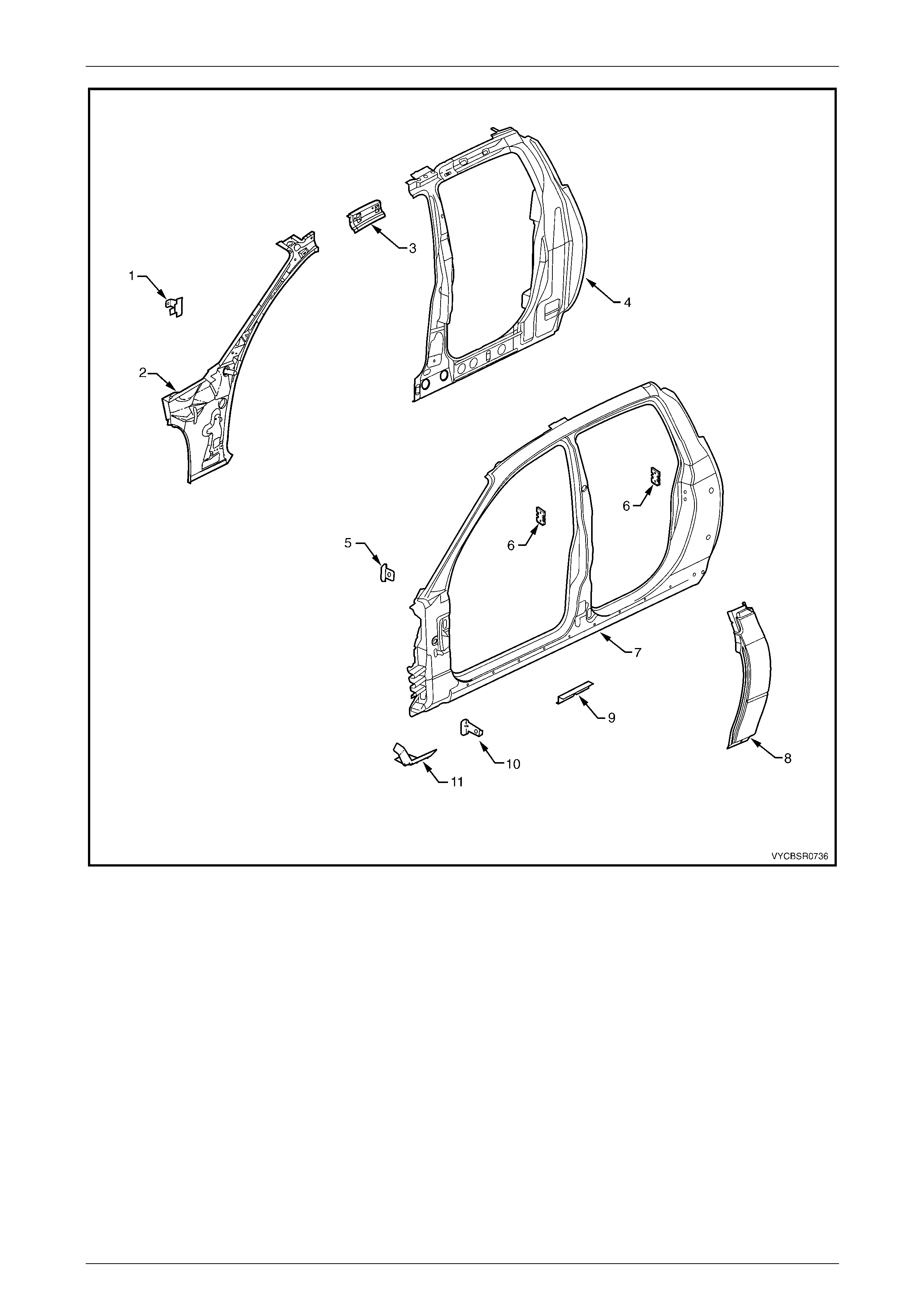
Figure 7F – 2
Legend
1 Hinge Pillar Trim Panel Bracket *, Left-hand / Right-hand
2 Hinge Pillar Inner Panel Assembly *, Left-hand / Right-hand
3 Quarter Panel Inner Extension *, Left-hand / Right-hand
4 Quarter Panel Inner Assembly, Left-hand / Right-hand
5 Fender Upper Rear Bracket, Left-hand / Right-hand
6 Door Striker Anchor Plate, Left-hand / Right-hand
7 Door Opening Frame Assembly, Left-hand / Right-hand
8 Rear Quarter Panel, Left-hand / Right-hand
9 Underbody Jacking Locator, Left-hand / Right-hand
10 Fender Rear Bracket, Left-hand / Right-hand
11 Fender Lower Rear Bracket, Left-hand / Right-hand
NOTE
• The door opening frame assembly (7)
includes parts 5, 6, 7, 9, 10 and 11.
• * For replacement procedures refer to
Section 7C Body Side – Utility.
7F Body Side – Crew Cab Page 7F–4
Page 7F–4
2 Service Operations
2.1 Rear Quarter Panel – Replace
Remove
1 Remove the adjacent bolt-on panels a nd components
as described in the appropriate Section Service
Information.
2 Remove the rear window, refer to Section 1A6
Stationary Windows in the MY 2005 VZ Service
Information.
3 Remove other adjacent pane ls as required, refer to the
relevant Section in this Supplement.
4 Spot cut the welds attaching the rear quarter panel to
the door opening frame assembly
refer to Figure 7F – 4.
Figure 7F – 3
Figure 7F – 4
5 Remove the rear quarter panel from the vehicle and rep air any damage to adjacent parts as required.
6 Check and rectify the alignme nt of the body as required, refer to Section 3F Body Construction – Crew Cab.
7F Body Side – Crew Cab Page 7F–5
Page 7F–5
Replace
NOTE
• Spot welding is the preferred method for
attaching of panels and should be used
whenever possible. Where the spot welding
equipment will not access the required weld
position, a plug weld should be performed.
• The same number and position of spot welds
(or plug welds) should be used when
replacing the panel, as was used during
manufacture, in order to maintain the original
structural strength of the vehicle.
1 As required, mark the new panel with drilling locations in preparation for plug welding. Drill holes as required.
2 Prepare all mating surfaces and treat with Weld Through Primer (Item 1) as required,
refer to Section 3F Body Construction – Crew Cab.
3 Clamp the rear quarter panel i n position.
4 Spot or plug weld the rear quarter panel to the door opening frame assembly, refer to Figure 7F – 5.
Figure 7F – 5
5 Refinish and paint panels and other components as required. Refer to Section 3 Body Construction.
6 Apply Joint Sealer (Item 3) as required, refer to Section 3F Body Construction – Crew Cab.
7 Apply Cavity Wax (Item 8) as required to the inside of any box secti ons or areas inaccessible to paint,
refer to Section 3F Body Construction – Crew Cab.
8 Apply Spray-on Dea dener (Item 7) where applicab le, refer to Section 3F Body Construction – Crew Cab.
9 Replace the rear window, refer to Section 1A6 Stationary Windows in the MY 2005 VZ Service Information.
10 Reinstall the remaining com ponents as described in the appr opriate Section in the MY 2005 VZ Service
Information.
7F Body Side – Crew Cab Page 7F–6
Page 7F–6
2.2 Door Opening Frame Assembly –
Replace
NOTE
This procedure requires the removal of the roof
panel. As an alternative, the door opening frame
assembly can be separated at the upper pillar
sections by following the procedures in Door
Opening Frame Assembly – Partial Replace,
Hinge Pillar, Centre Pillar and Lock Pillar in this
Section.
Remove
1 Remove the adjacent bolt-on panels a nd components
as described in the appropriate Section of th e MY
2005 VZ Service Information.
2 Remove the front and rear door assemblies, refer to
Section 8 Doors, Liftgate and Endgate.
3 Remove the windshield and rear window, refer to
Section 1A6 Stationary Windows in the MY 2 005 VZ
Service Information.
4 Remove the dash panel retaining bolt from the hinge
pillar.
5 Remove the roof panel, refer to Section 9F Roof.
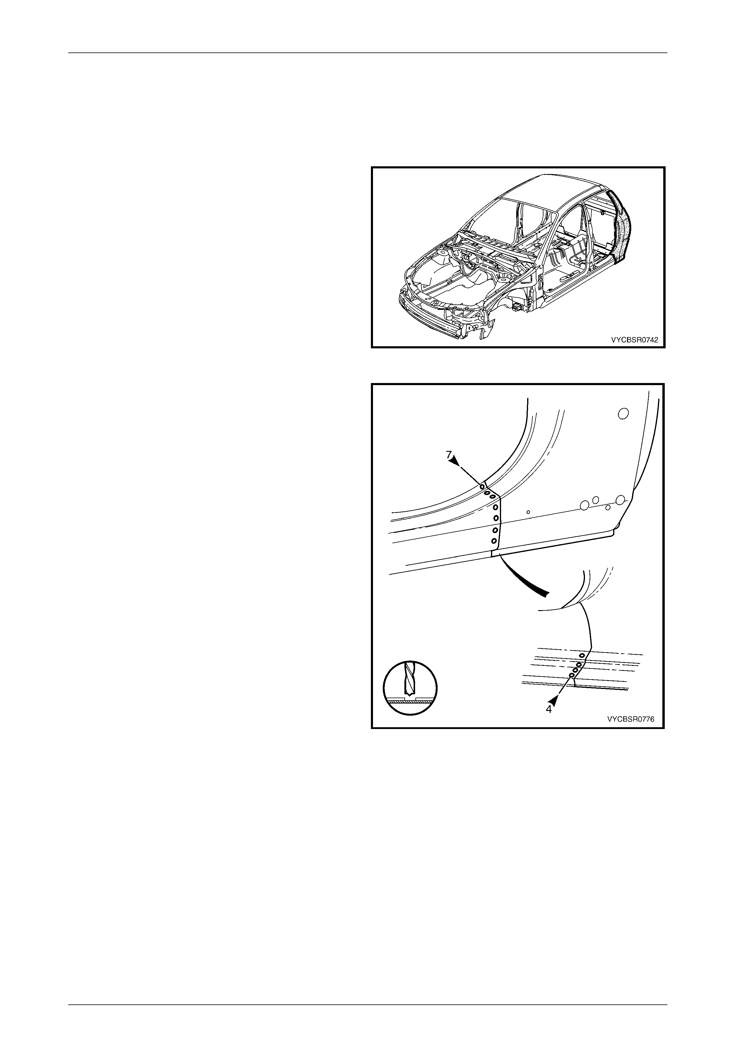
Figure 7F – 6
6 Remove the rear quarter panel, refer to 2.1 Rear Quarter Panel – Replace.
7 Remove the front wheelhouse panel upper side rail, refer to Section 4 Front End.
8 Remove other adjacent pane ls as required, refer to the relevant Section in this Supplement.
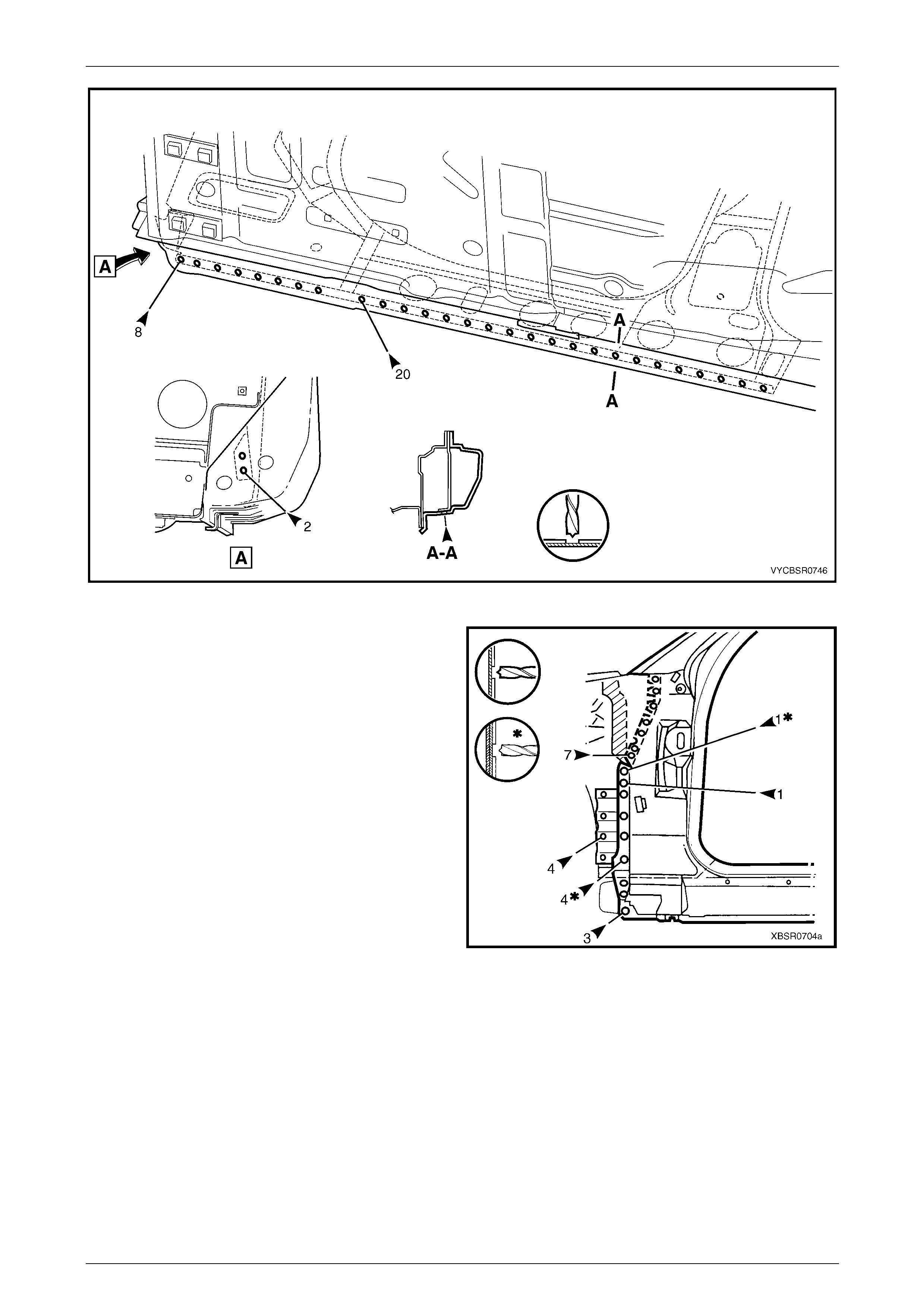
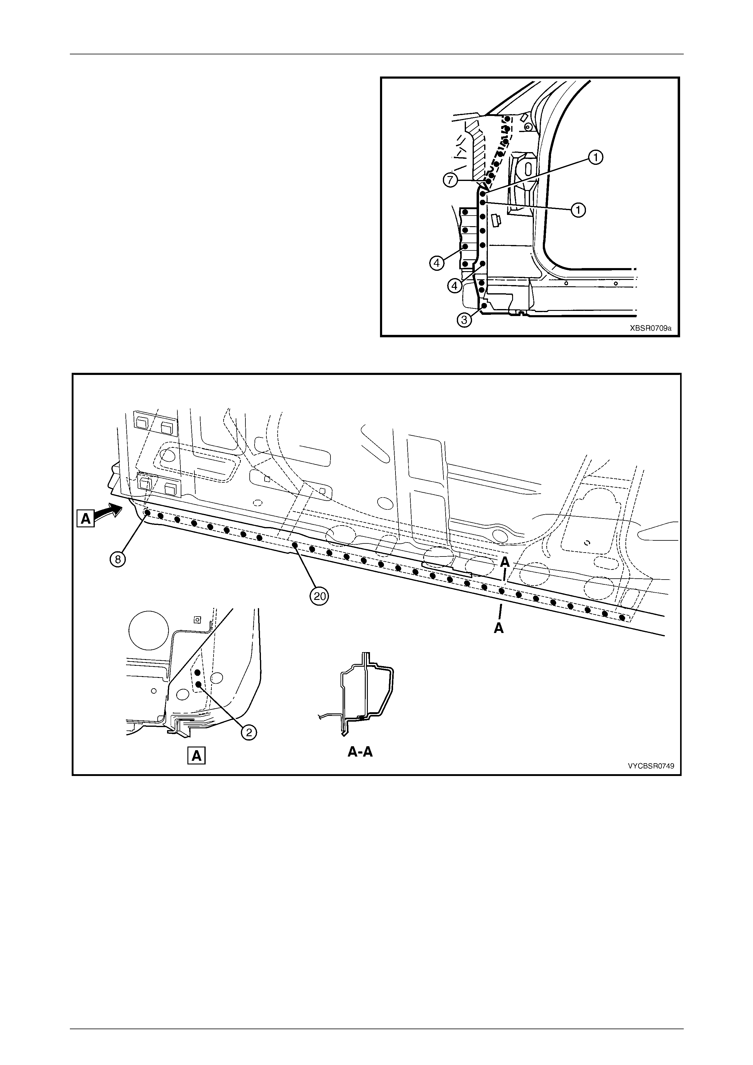
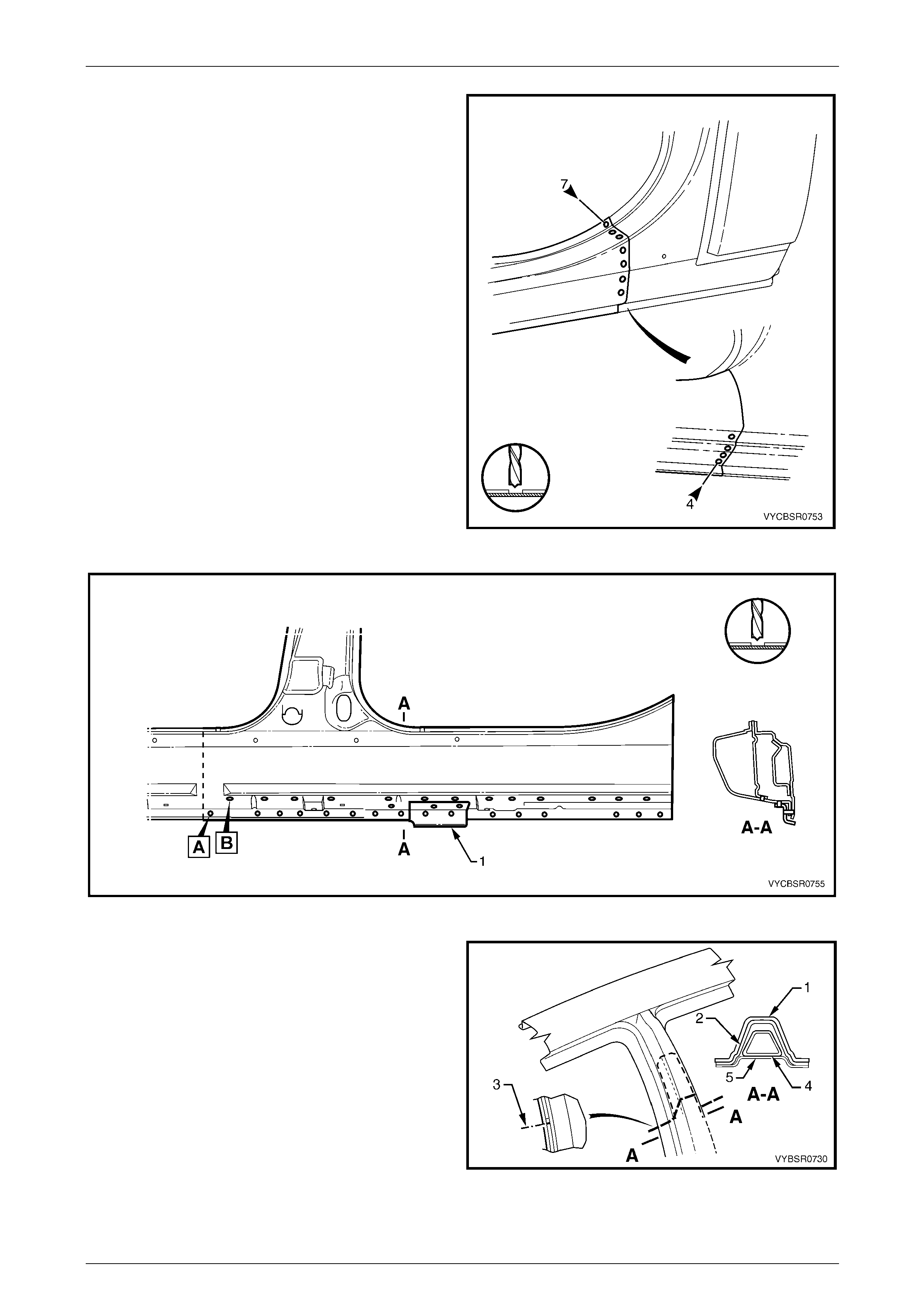
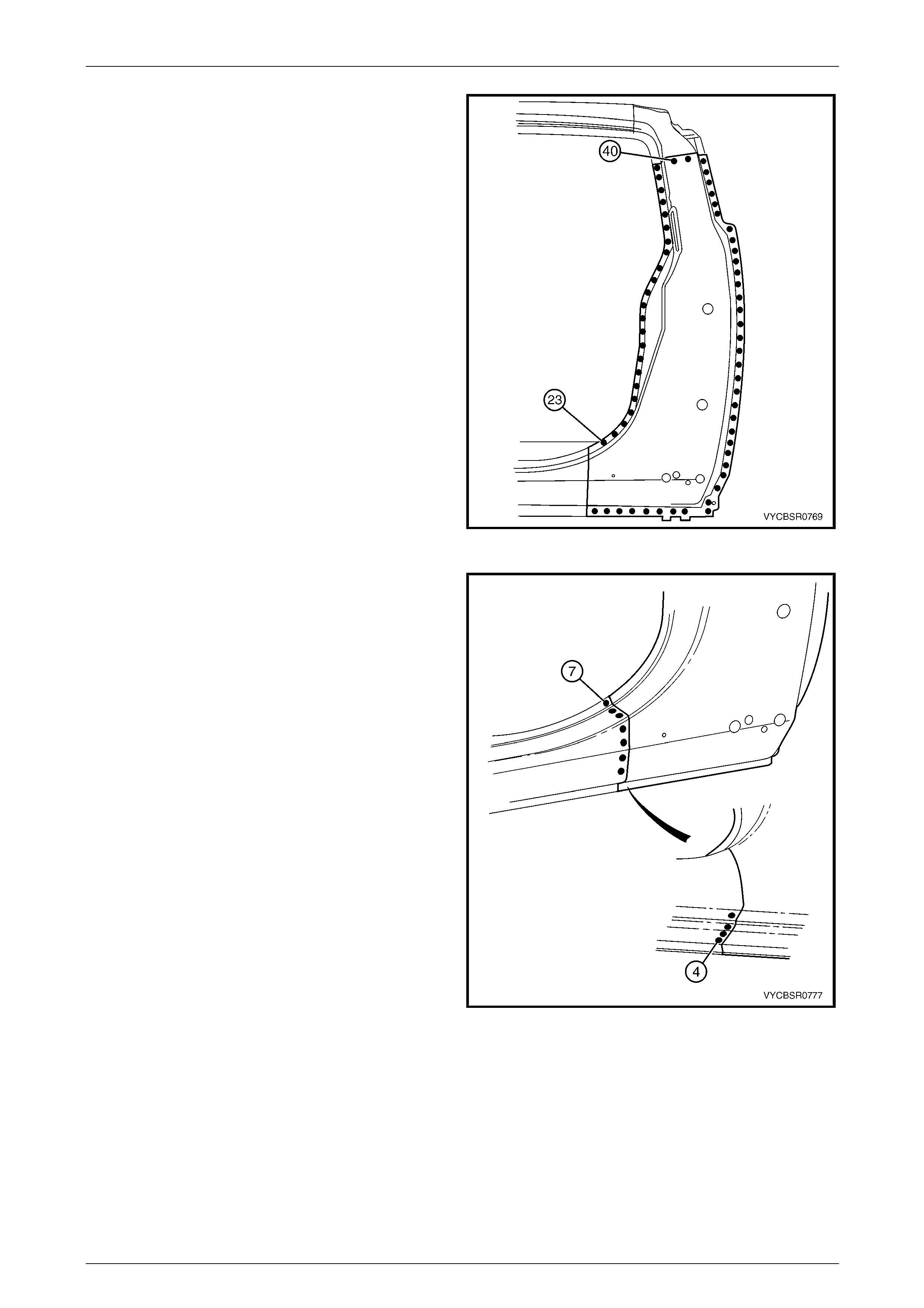
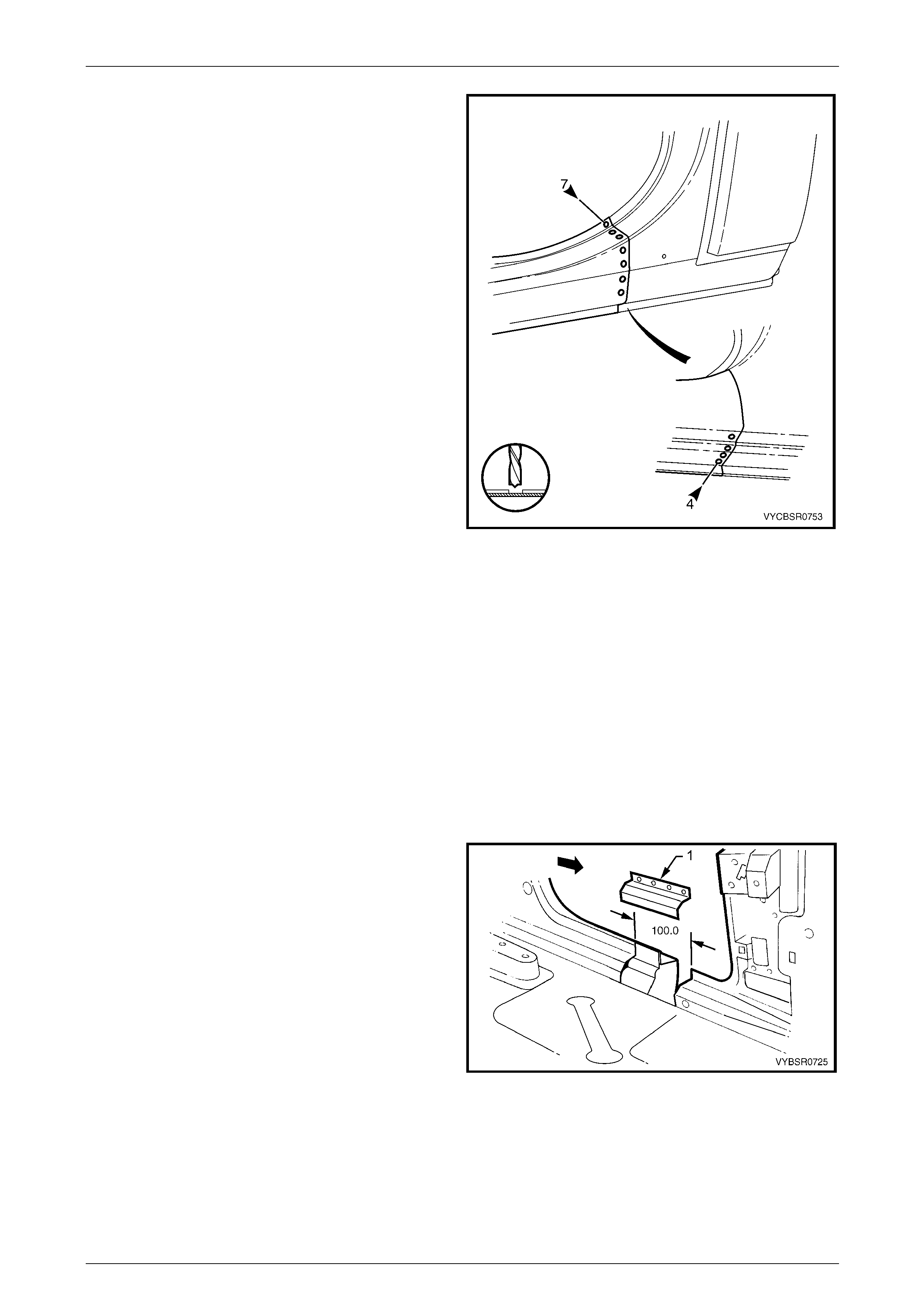
9 Spot cut along the vertical flange below the rocker panel to separate the door opening frame assembly from the
inner rocker panel and front floor panel extension assembly, refer to Figure 7F – 7.
Figure 7F – 7
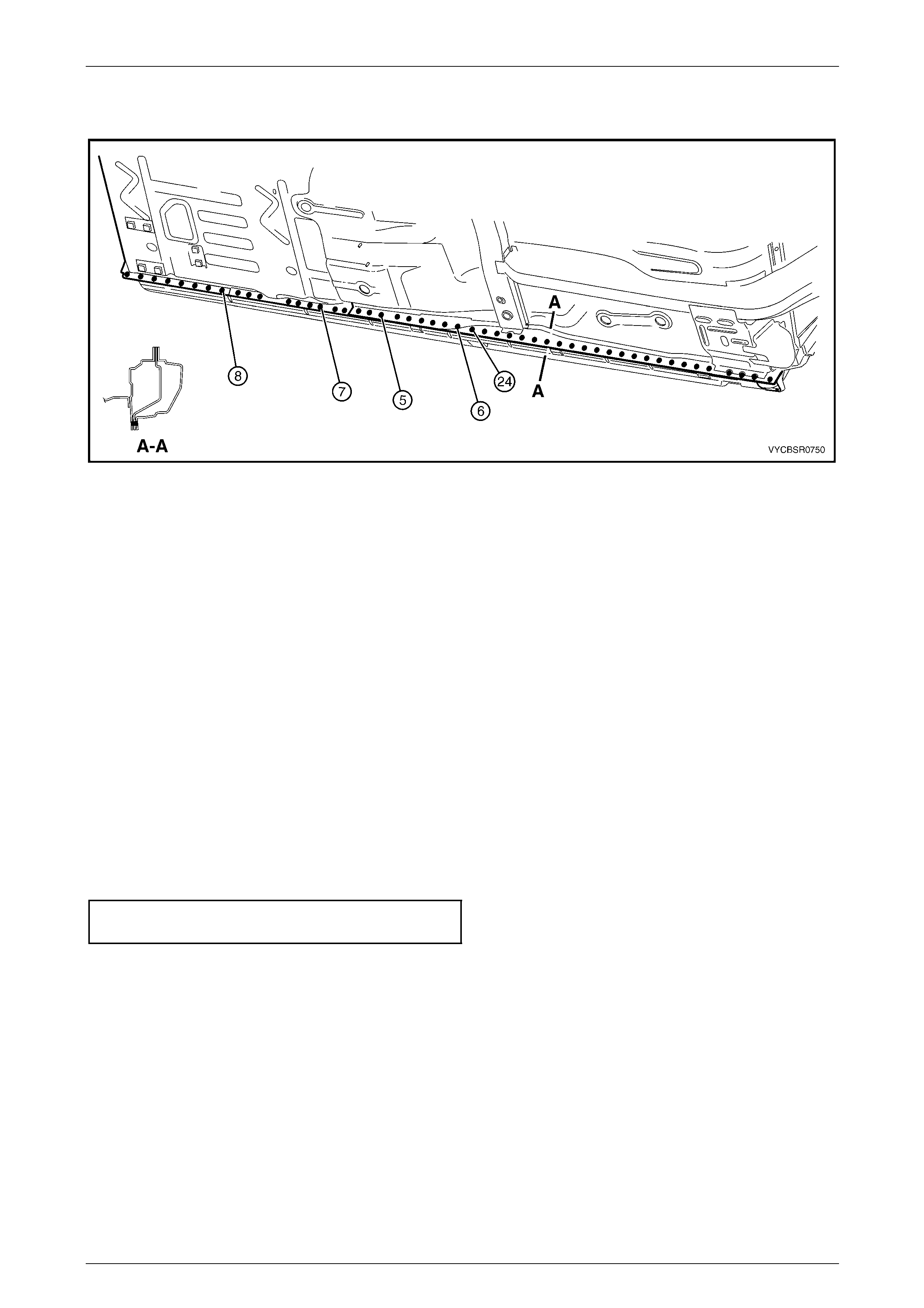
10 Spot cut from below, up into the rocker panel, the welds attaching the door opening frame assembly to the quarter
panel inner assembly, refer to Figure 7F – 8.
7F Body Side – Crew Cab Page 7F–7
Page 7F–7
Figure 7F – 8
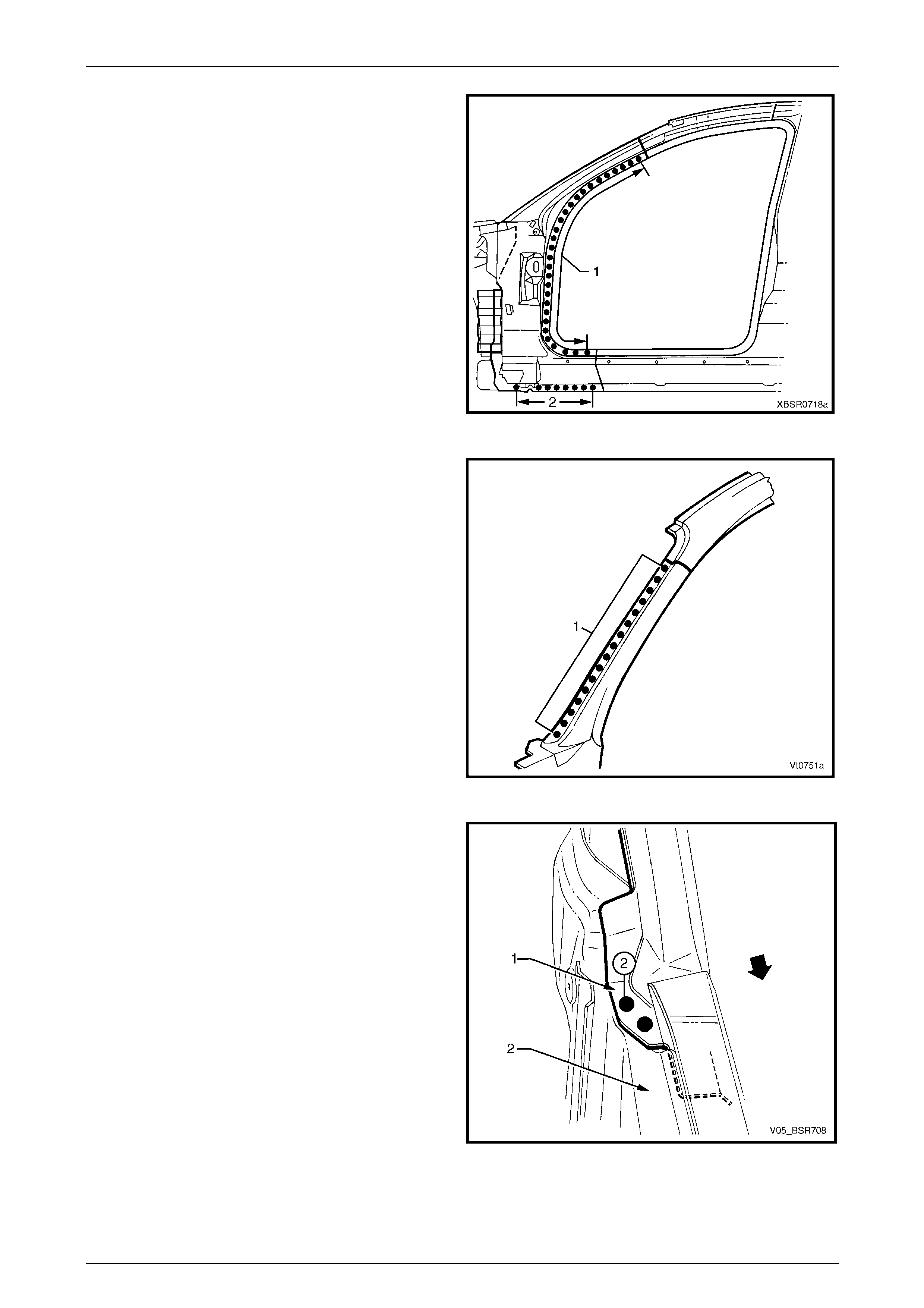
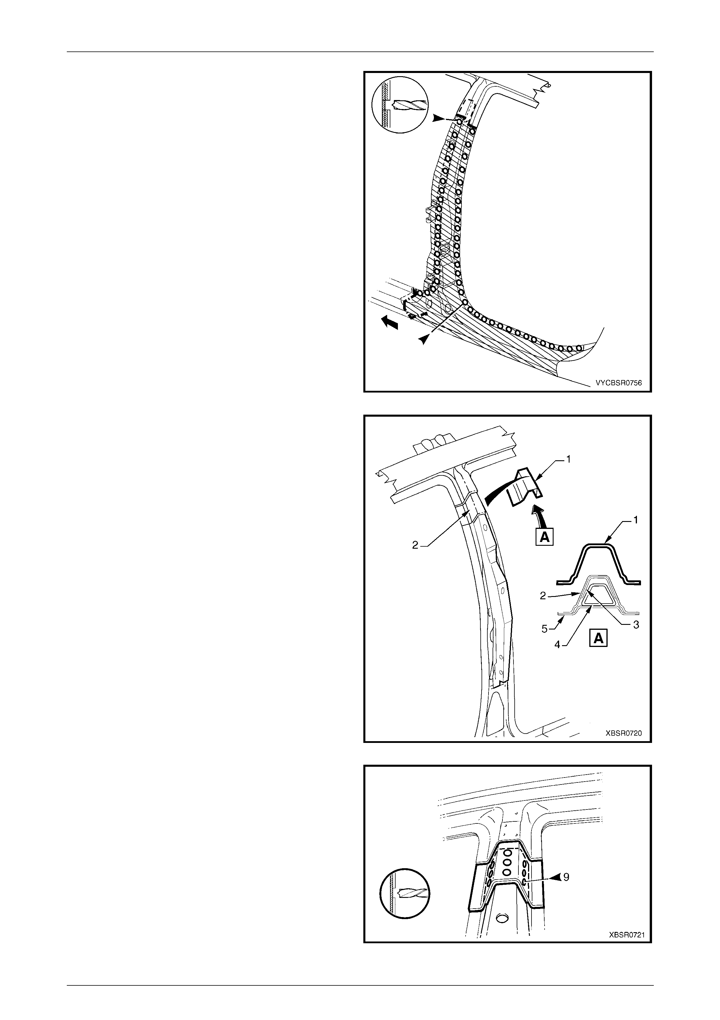
11 Spot cut the welds attaching the door openin g frame
assembly to the inner rocker panel and to the hin ge
pillar inner panel assembly.
NOTE
In order to spot cut the uppermost of these welds
it may be necessary to cut and peel back the
section of hinge reinforcement panel covering
the welds, to gain the required access.
Figure 7F – 9
7F Body Side – Crew Cab Page 7F–8
Page 7F–8
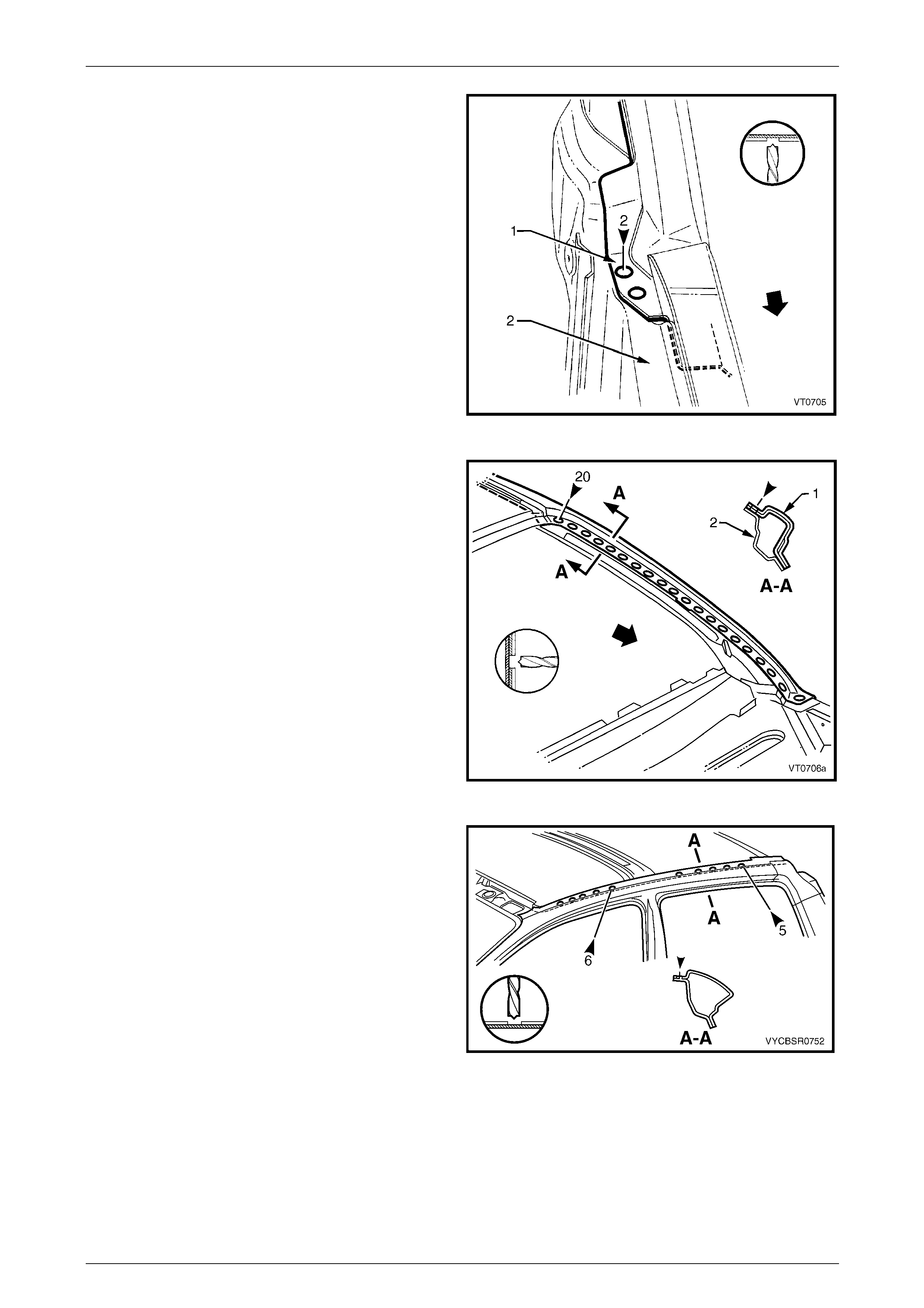
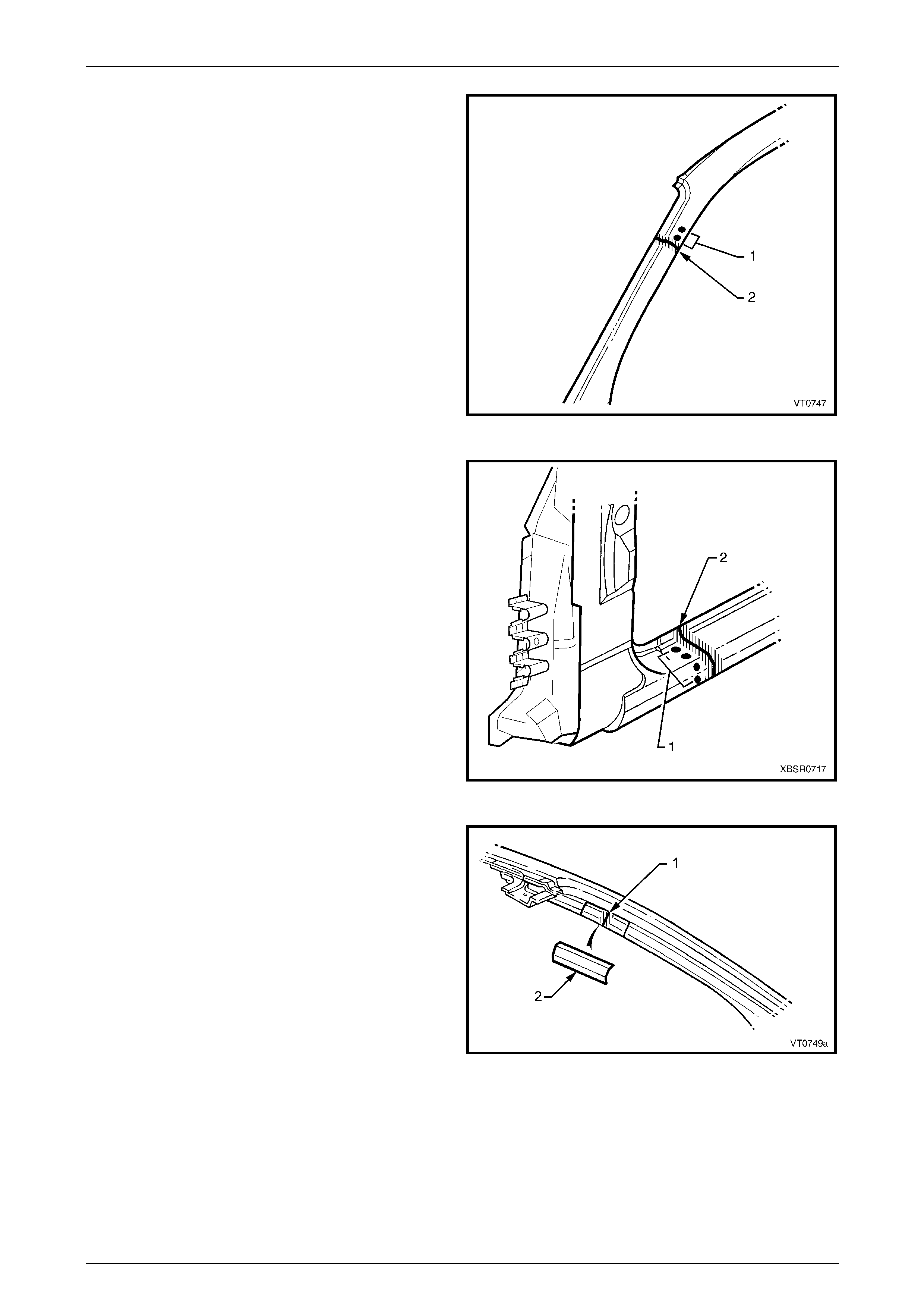
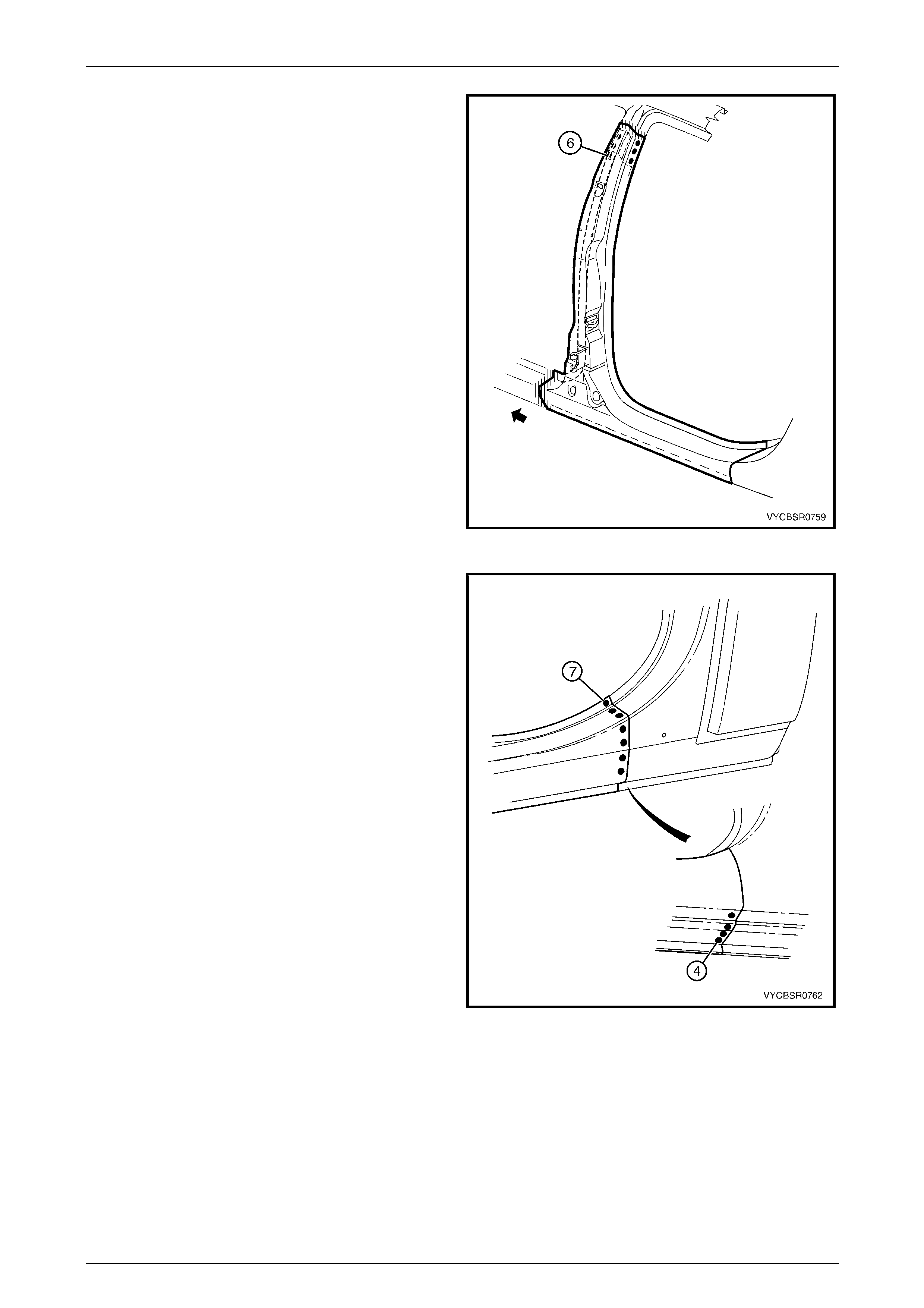
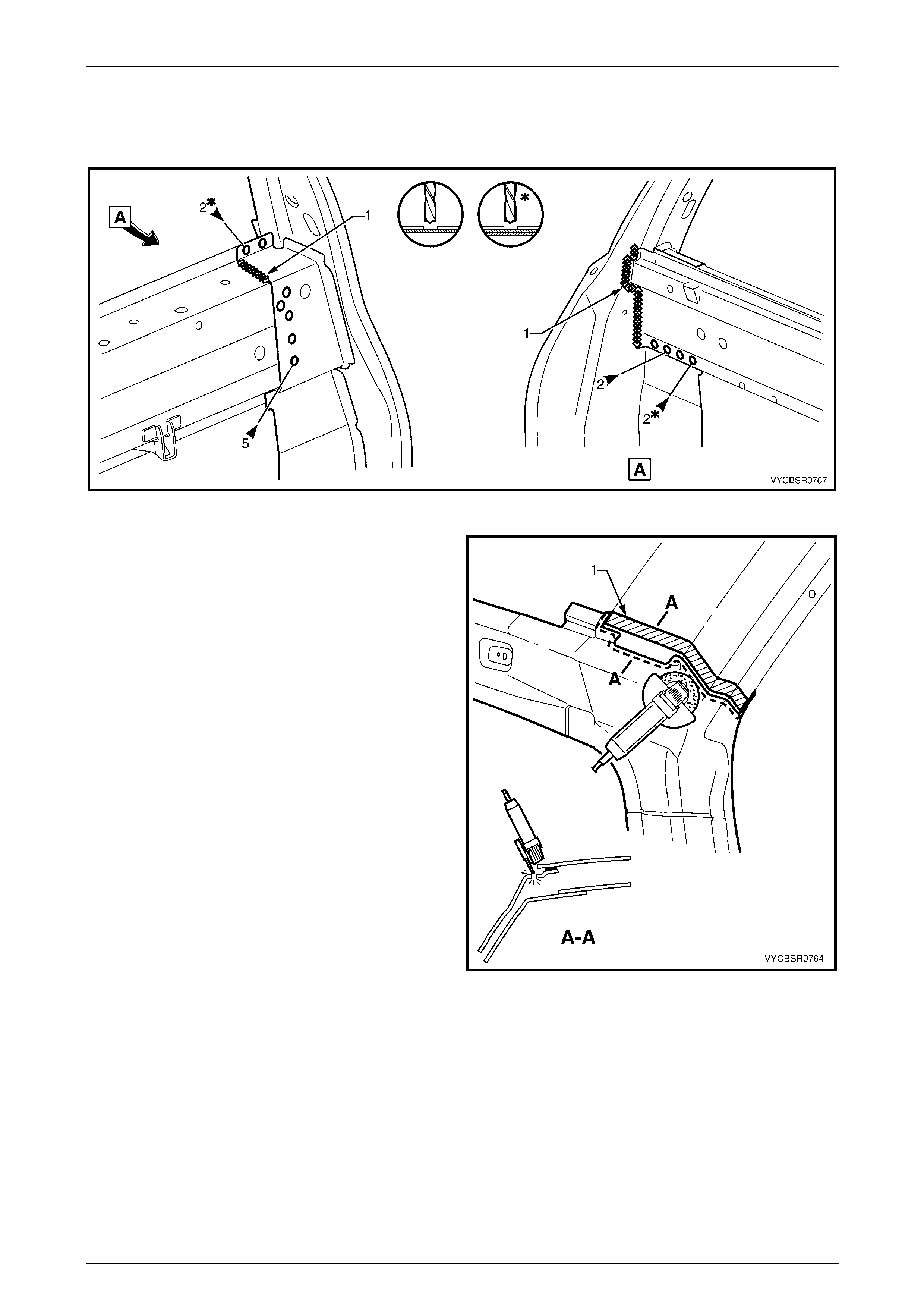
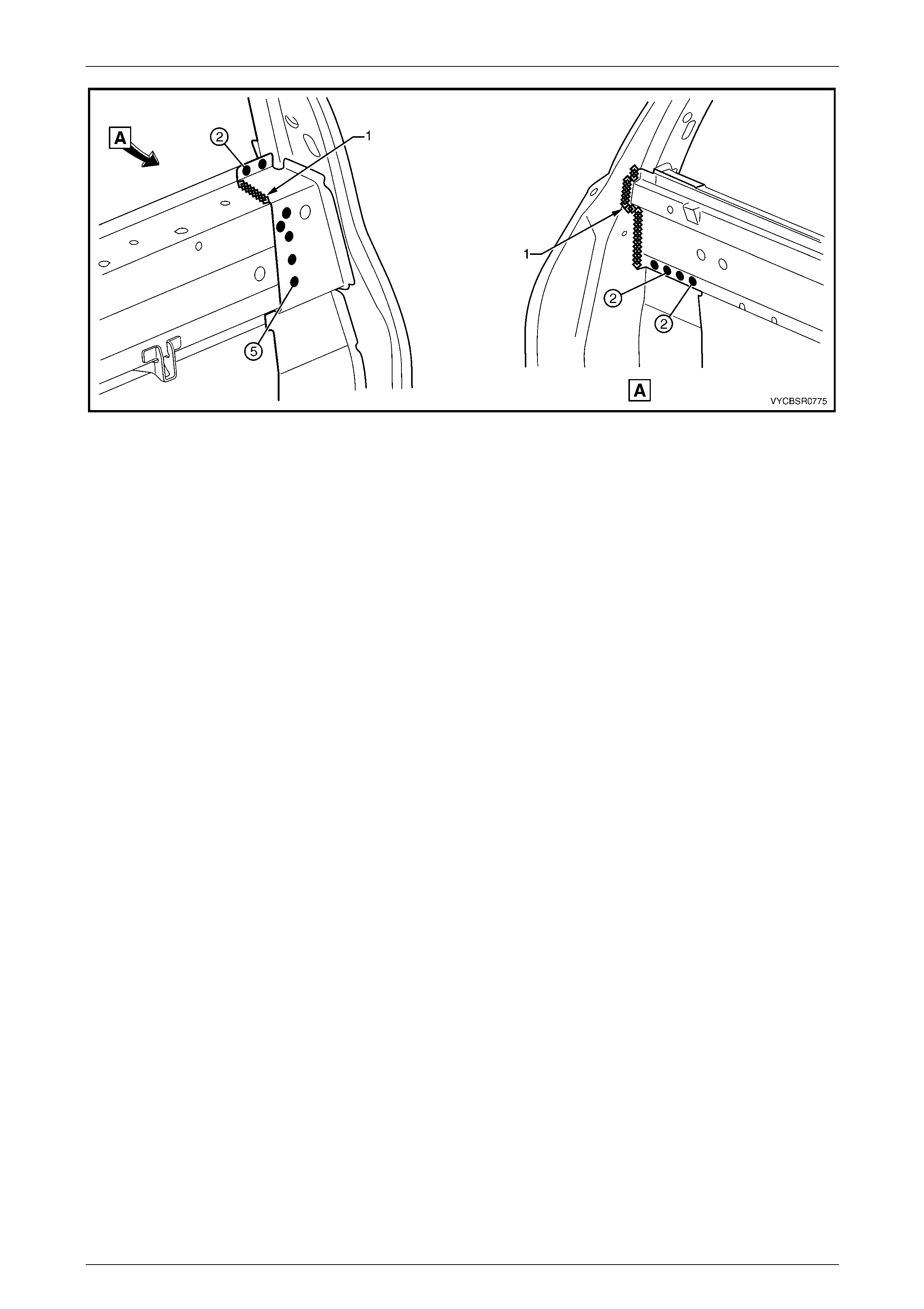
12 Spot cut the two welds at the base of the hinge pillar,
attaching the door opening frame assembly (1) to the
hinge pillar inner panel assembly (2).
Figure 7F – 10
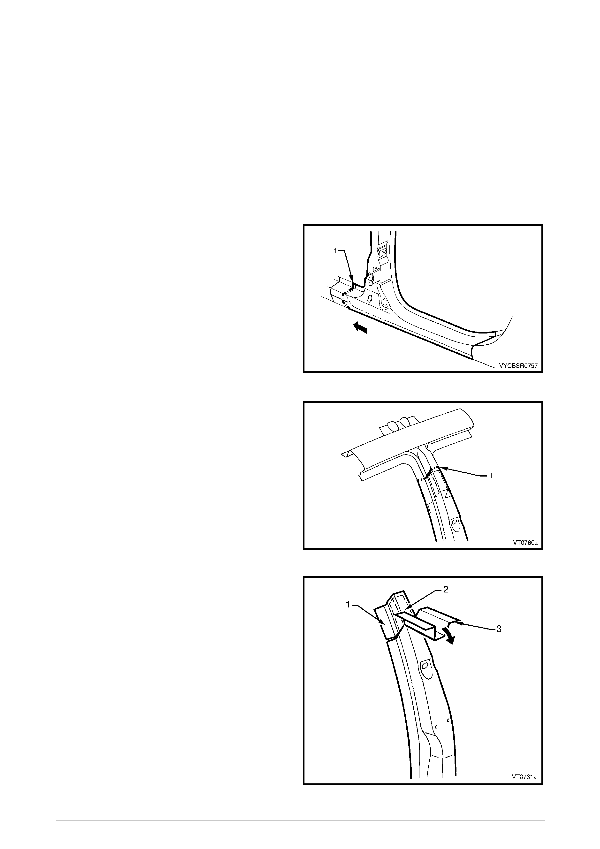
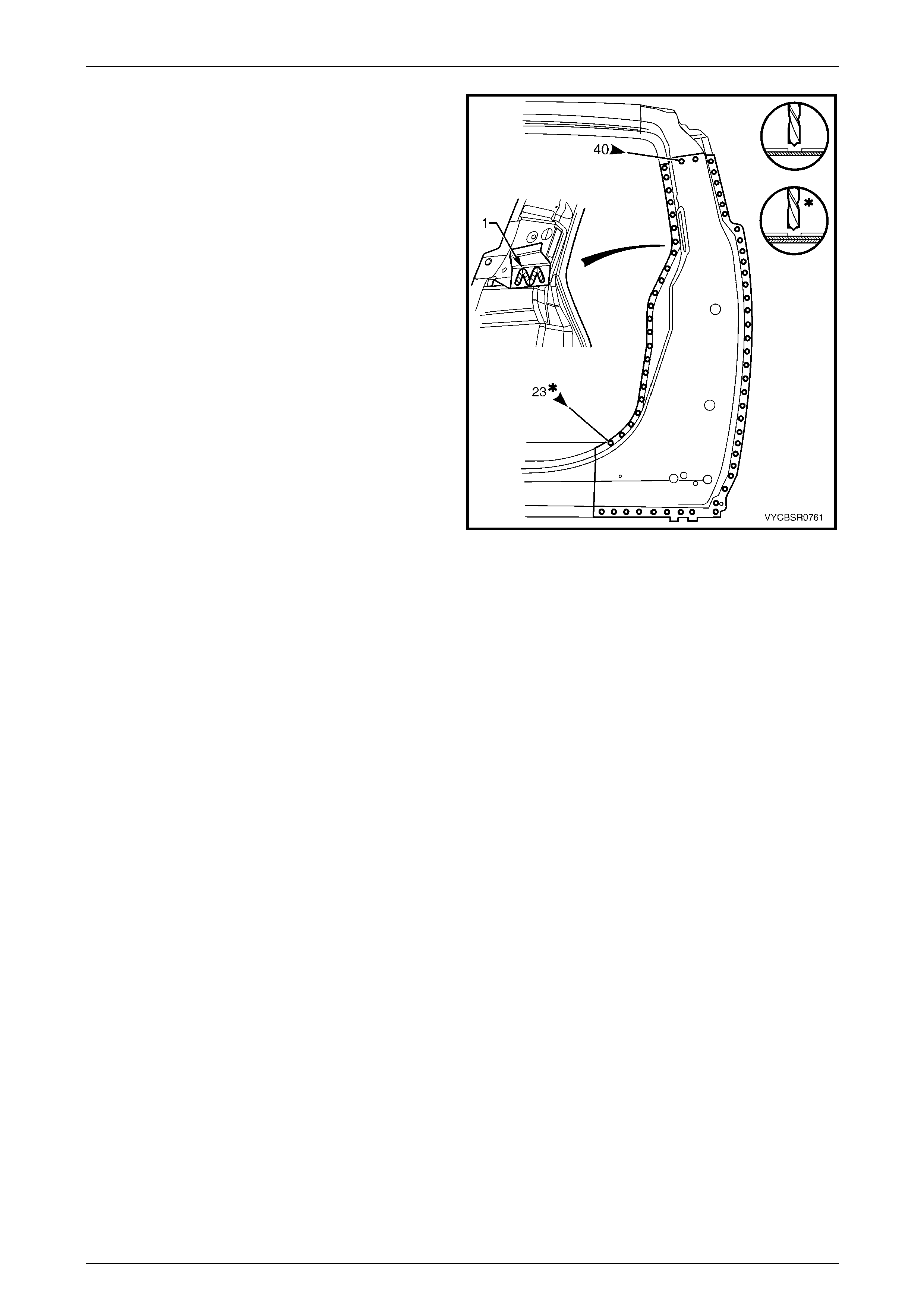
13 Spot cut the welds on the windshield side flange,
attaching the door opening frame assembly (1) to the
hinge pillar inner panel assembly (2).
Figure 7F – 11
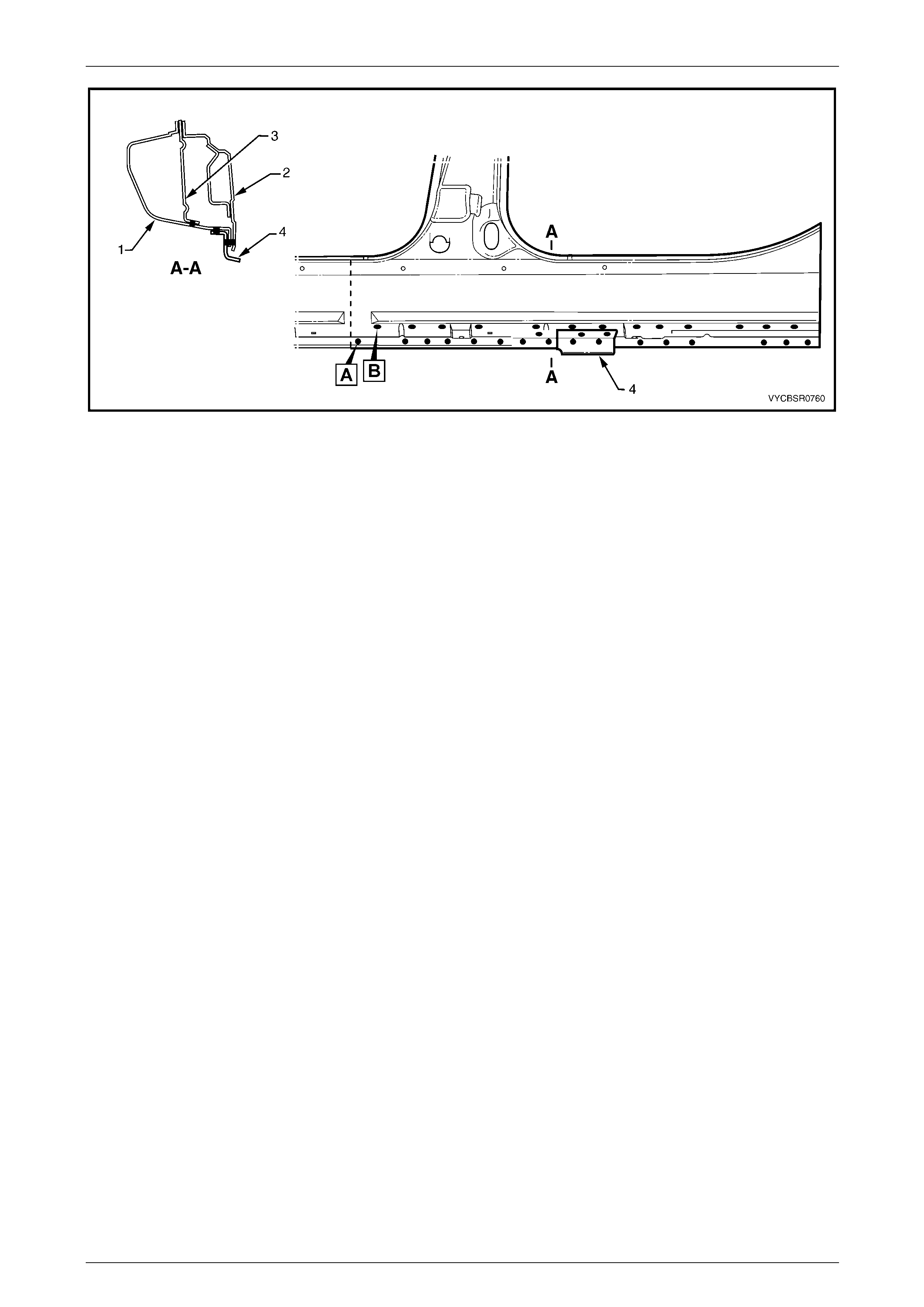
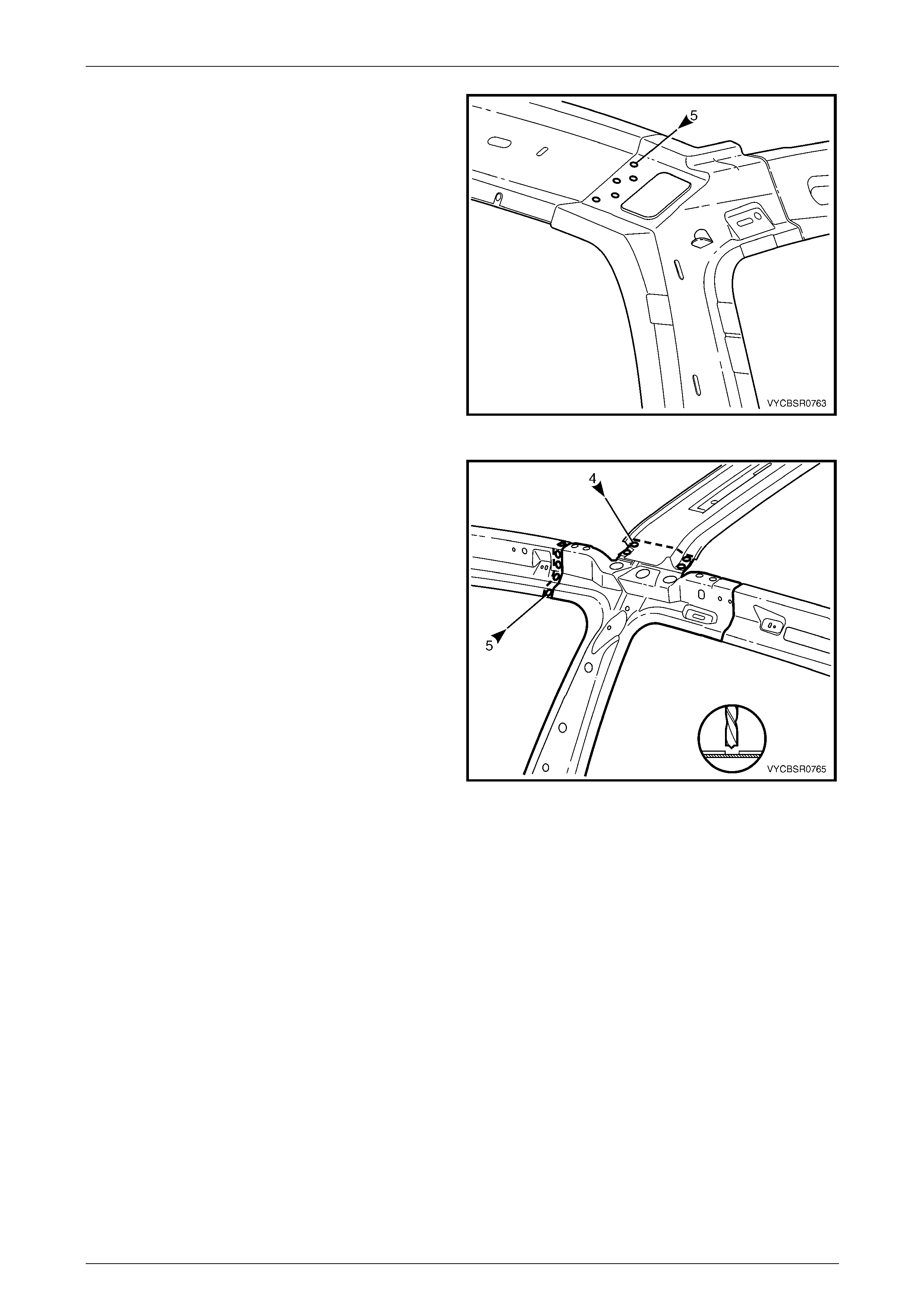
14 Spot cut the welds along the roof flange, attaching the
door opening frame assembly to the quarter p anel
inner assembly.
NOTE
Many of these welds may have been removed
with the roof panel.
Figure 7F – 12
7F Body Side – Crew Cab Page 7F–9
Page 7F–9
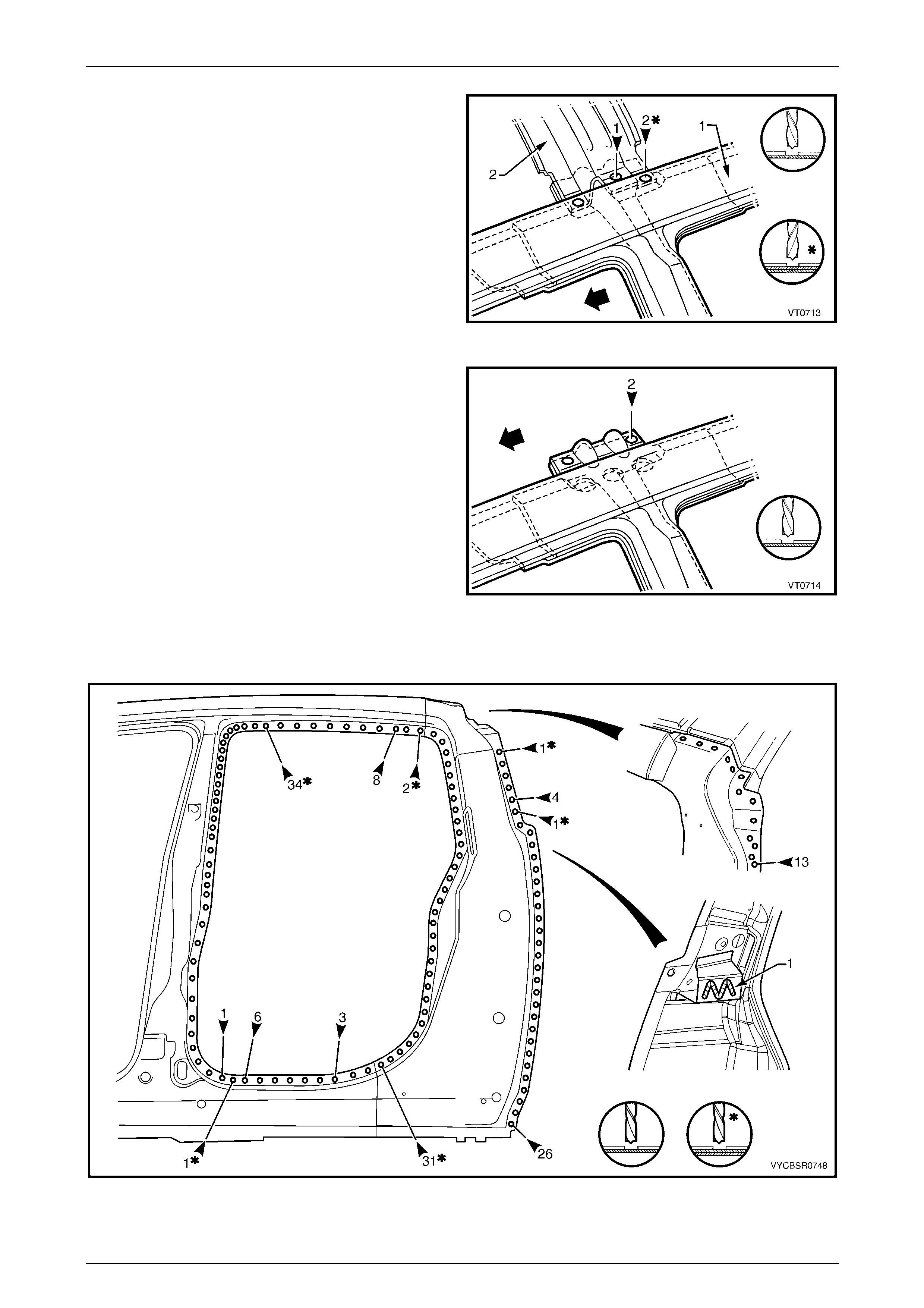
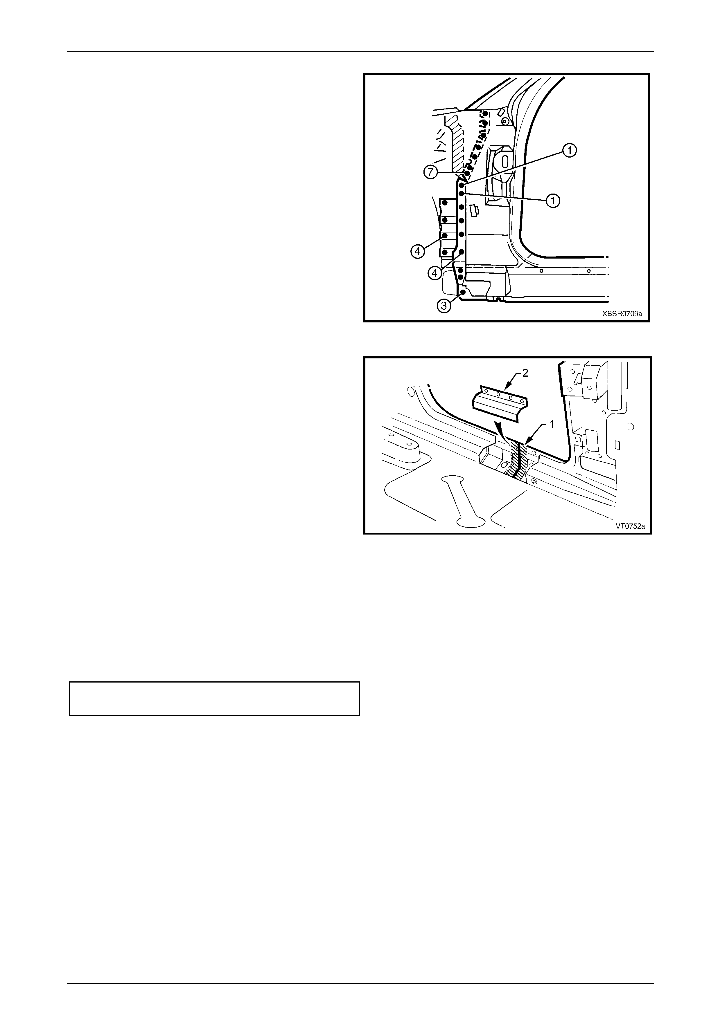
15 Spot cut the two welds attaching the roof bow panel
(2) to the centre pillar upper reinforcement, and the
single weld attaching the roof bow panel to the door
opening frame assembly (1).
Figure 7F – 13
16 Carefully lifting the roof bow panel out of the way, spot
cut the two welds attaching the centre pillar upper
reinforcement to the quarter panel inn er asse mbly.
The centre pillar upper reinforcement is removed as
part of the door opening frame assembl y.
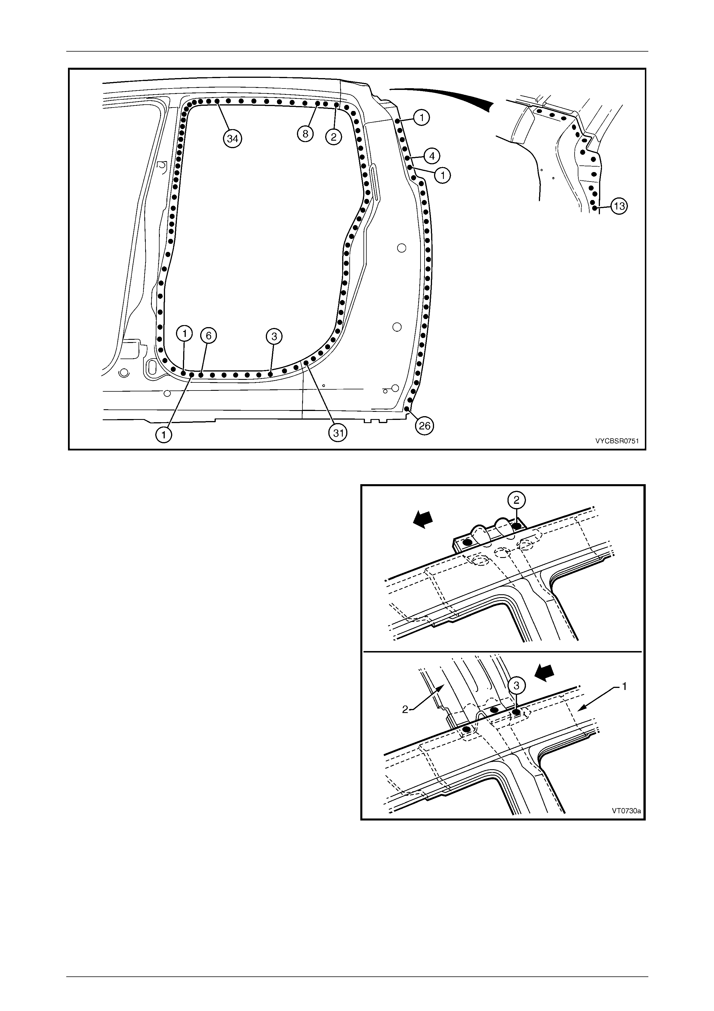
17 Spot cut the welds around the rear door opening frame
rear flange and rear door opening flan ge, refer to
Figure 7F – 15.
NOTE
Structural adhesive is applied to the C-pillar
reinforcement (1), adhering it to the quarter
panel inner, which will require cutting. Prise the
door opening frame panel and rough-cut the
reinforcement, then grind off the remaining part
once the door opening frame assemb l y has been
removed.
Figure 7F – 14
Figure 7F – 15
7F Body Side – Crew Cab Page 7F–10
Page 7F–10
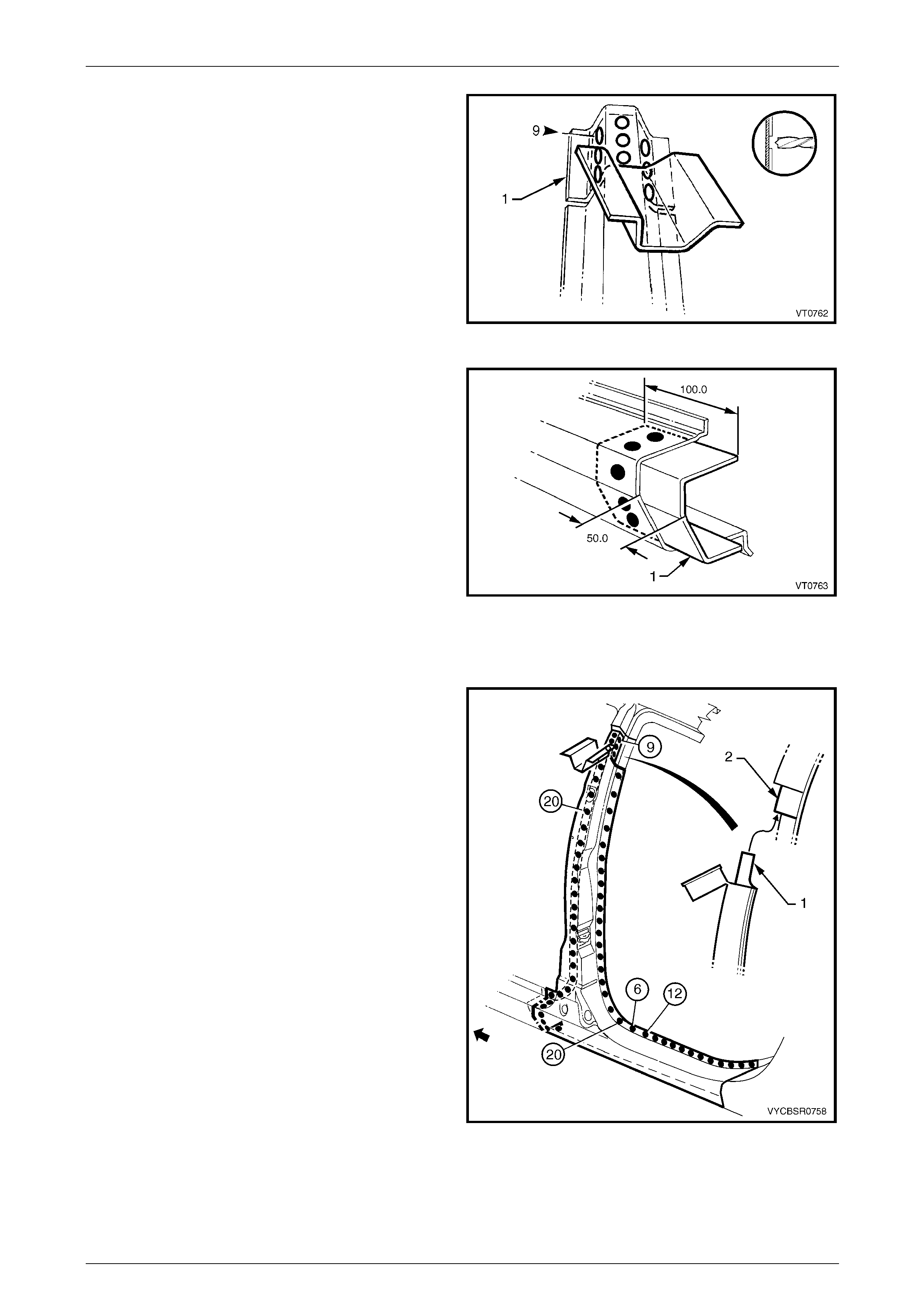
18 Spot cut the welds on the flange surrounding the front
door opening, attaching the door op ening frame
assembly to the hinge pillar inner pa nel assembly,
inner rocker panel and quarter panel inner assembly.
19 Remove the complete door opening frame assembly
and repair any dama ge to adjacent parts as required.
20 Check and rectify the alignme nt of
the body as required, refer to
Section 3F Body Construction – Crew Cab.
Figure 7F – 16
Replace
NOTE
• Spot welding is the preferred method for
attaching of panels and should be used
whenever possible. Where the spot welding
equipment will not access the required weld
position, a plug weld should be performed.
• The same number and position of spot welds
(or plug welds) should be used when
replacing the panel, as was used during
manufacture, in order to maintain the original
structural strength of the vehicle.
1 As required, mark the new panel with drilling locations in preparation for plug welding. Drill holes as required.
2 Prepare all mating surfaces and treat with Weld Through Primer (Item 1) as requir ed,
refer to Section 3F Body Construction – Crew Cab.
3 Apply Acrylic Spot Weld Sealer (Item 2), refer to Section 3F Body Construction – Crew Cab.
4 Apply Structural Adhesive (Item 6), refer to Section 3F Body Constructio n – Crew Cab.
5 Securely clamp the door openin g frame assembly in
position on the vehicle body.
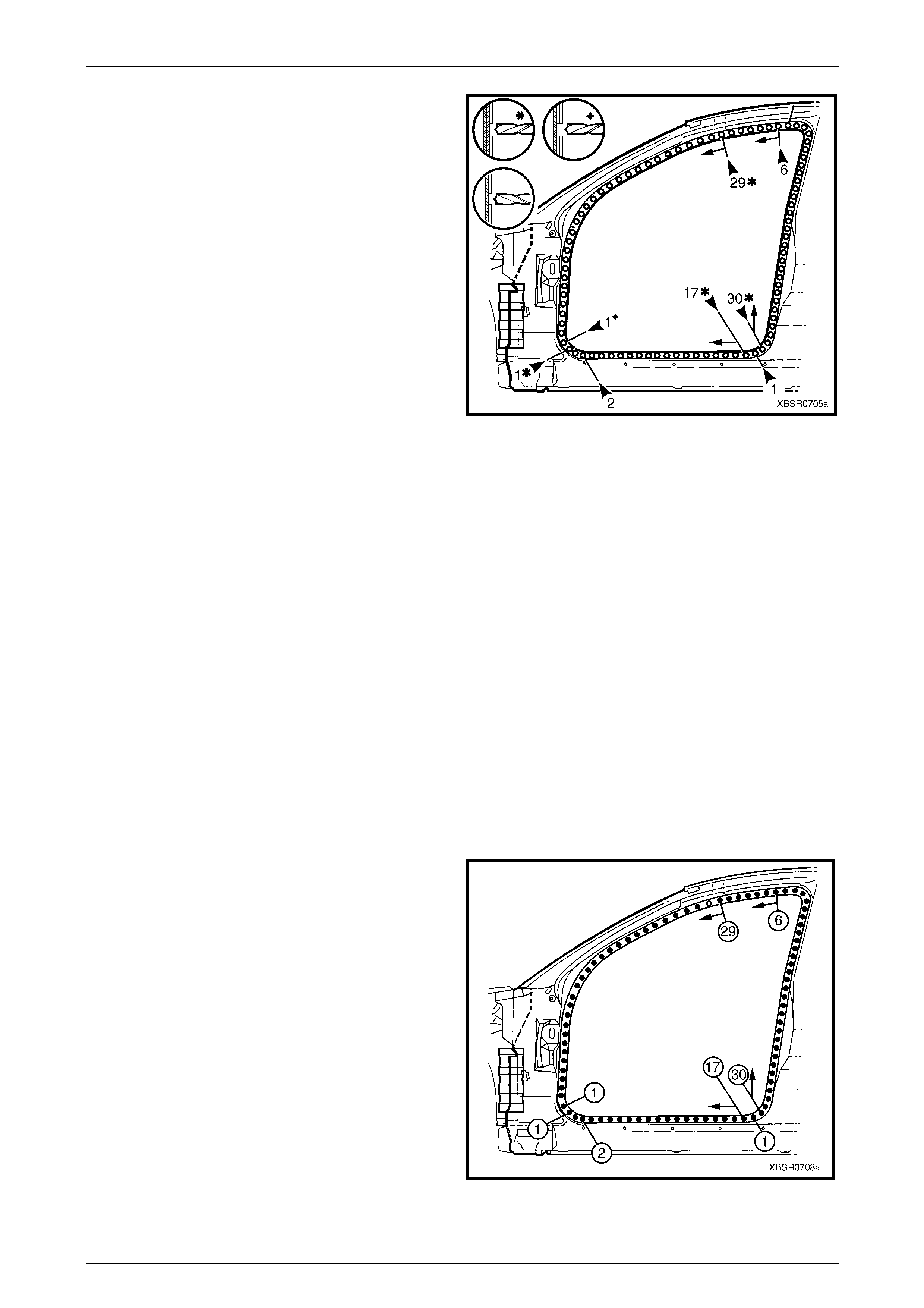
6 Spot or plug weld around the front door opening
flange.
7 Spot or plug weld the door openi ng frame assembly
around the rear door opening flange and rear flange,
refer to Figure 7F – 18.
Figure 7F – 17
7F Body Side – Crew Cab Page 7F–11
Page 7F–11
Figure 7F – 18
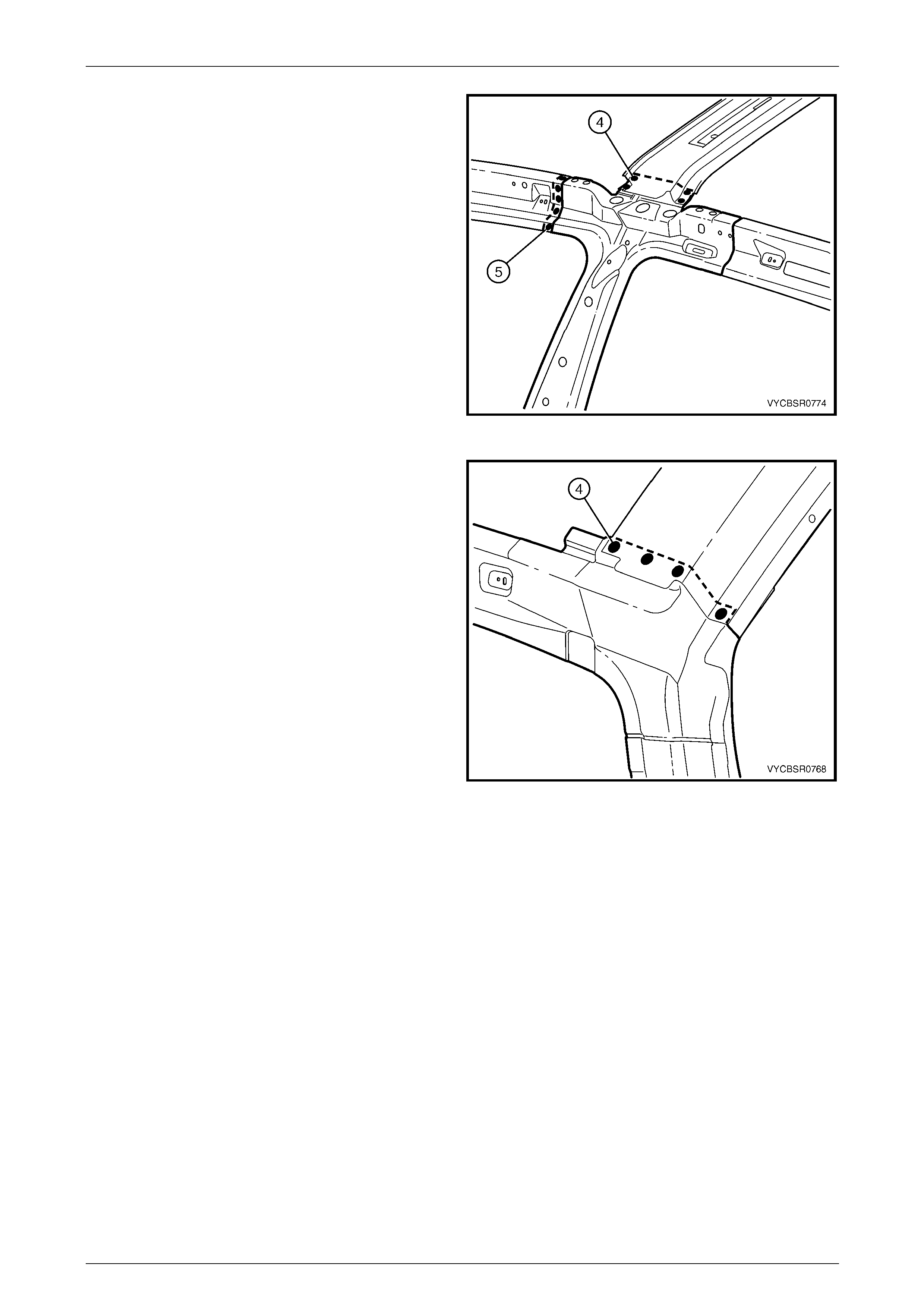
8 Spot or plug weld the door opening frame assembly
(1) to the quarter panel inner assembly, then spot or
plug weld the roof bow panel (2) to the door opening
frame assembly as shown.
Figure 7F – 19

7F Body Side – Crew Cab Page 7F–12
Page 7F–12
9 Spot or plug weld the door opening frame assembly
along the roof flange several places.
NOTE
The remaining welds are made when the roof
panel is installed.
Figure 7F – 20
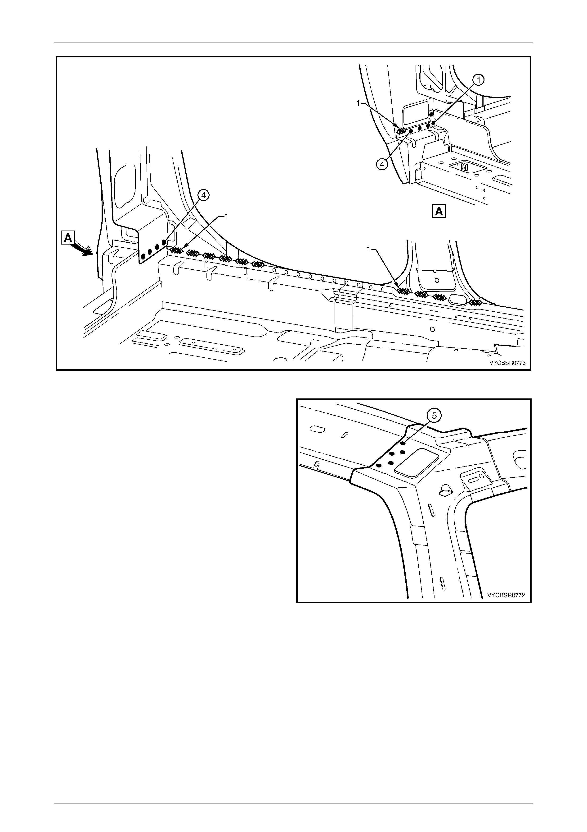
10 Spot weld along the windshield flange, attaching the
door opening frame assembly to the hinge pillar inner
panel assembly.
Figure 7F – 21
11 Spot or plug weld the door opening frame assembly
(1) to the hinge pillar inner panel assembly (2) at the
base of the hinge pillar.
Figure 7F – 22
7F Body Side – Crew Cab Page 7F–13
Page 7F–13
12 Spot or plug weld the door opening frame assembly to
the inner rocker panel and to the hinge pillar inner
panel assembly.
NOTE
If the sheetmetal was modified to allow access to
these welds, it should be repaired to its original
configuration.
13 Plug weld up through the rocker panel to attach the
door opening frame assembly to the quarter p anel
inner assembly. Refer to Figure 7F – 24.
Figure 7F – 23
Figure 7F – 24
7F Body Side – Crew Cab Page 7F–14
Page 7F–14
14 Spot or plug weld the door opening frame assembly along the vertical flange below the rocker panel,
refer to Figure 7F – 25.
Figure 7F – 25
15 Replace the front wheelhouse panel upper side rail, refer to Section 4 Front End.
16 Replace the rear quarter panel, refer to 2.1 Rear Quarter Pane l – Replace.
17 Replace the roof panel, refer to Section 9F’ Roof.
NOTE
Refinish and prime any bare metal as required
prior to replacing these panel s.
18 Install the door hinges, refer to Section 8 Do ors, Liftgate and Endgate.
19 Replace other adjoining removed pa nels as required, refer to the relevant Section in this Supp lement.
20 Refinish and paint panels and other components as required. Refer to Section 3 Body Construction.
21 Apply Joint Sealer (Item 3) as required. Refer to Section 3F Body Construction – Crew Cab.
22 Apply Cavity Wax (Item 8) as required to the inside of any box secti ons or areas inaccessible to paint,
refer to Section 3F Body Construction – Crew Cab.
23 Apply Spray-on Dea dener (Item 7) where applicab le, refer to Section 3F Body Construction – Crew Cab.
24 Install the dash panel retaining bolt throu gh the hinge pil lar and tighten to the specified torque.
Dash panel retaining b olt
torque specification.........................................35.0 – 45.0 Nm
25 Replace the windshield and rear window, refer to Section 1 A 6 Stationary Windows in the MY 2005 VZ Service
Information.
26 Insert Cavity Foam into the hinge and centre pillars as required, refer to Section 2 Precautions.
27 Reinstall the front and rear do or assemblies, refer to Section 8 Doors, Liftgate and Endgate.
28 Install the remaining components as described in the appropriate Section in the MY 2005 VZ Service Information.
7F Body Side – Crew Cab Page 7F–15
Page 7F–15
2.3 Door Opening Frame Assembly – Partial
Replace, Hinge Pillar
Remove
1 Remove the adjacent bolt-on panels a nd components
as described in the appropriate Section of th e MY
2005 VZ Service Information.
2 Remove the front door assembly, refer to
Section 8 Doors, Liftgate and Endgate.
3 Remove the windshield, refer to
Section 1A6 Stationary Windows in the MY 2 005 VZ
Service Information.
4 Remove the dash panel retaining bolt from the hinge
pillar.
5 Remove the front wheelhouse pan el upper side rail,
refer to Section 4 Front End.
6 Remove other adjacent bolt-o n panels and
components as described in the appropriate Section of
the MY 2005 VZ Service Information.
7 Secure an appropriate tool between the front door
opening flanges to maintain correct bod y alignment.
Figure 7F – 26
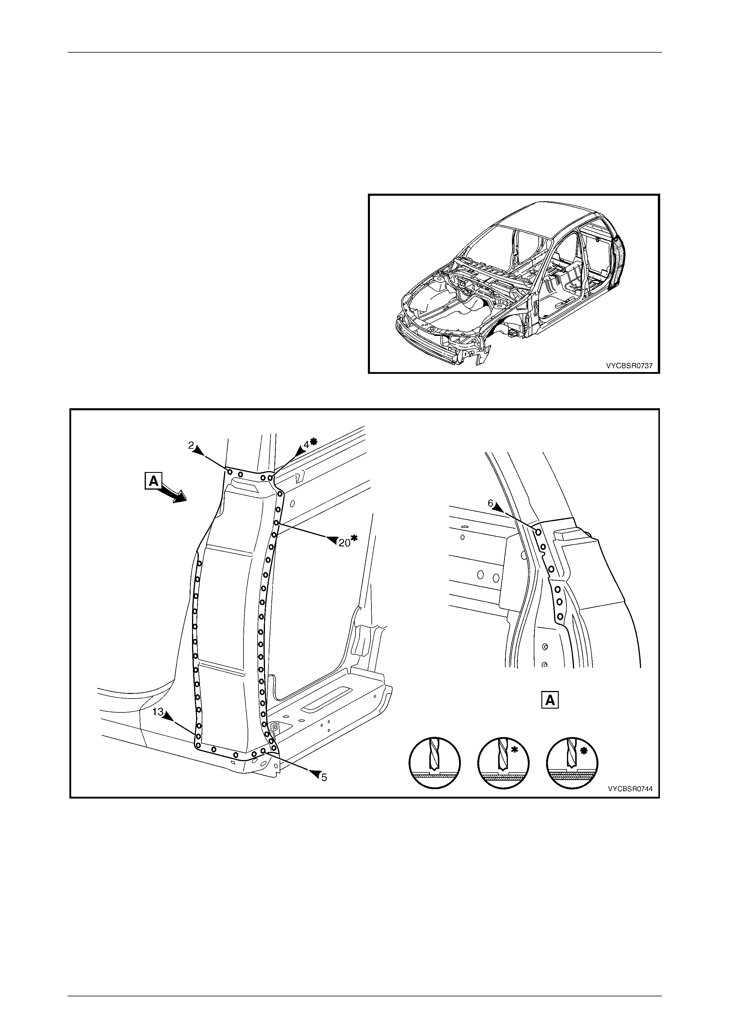
8 Spot cut the welds attaching the door openin g frame
assembly to the inner rocker panel and to the hin ge
pillar inner panel assembly.
NOTE
In order to spot cut the uppermost of these welds
it may be necessary to cut and peel back the
section of hinge reinforcement panel covering
the welds, to gain the required access.
Figure 7F – 27
7F Body Side – Crew Cab Page 7F–16
Page 7F–16
9 Spot cut the two welds at the base of the hinge pillar,
attaching the door opening frame assembly (1) to the
hinge pillar inner panel assembly (2).
Figure 7F – 28
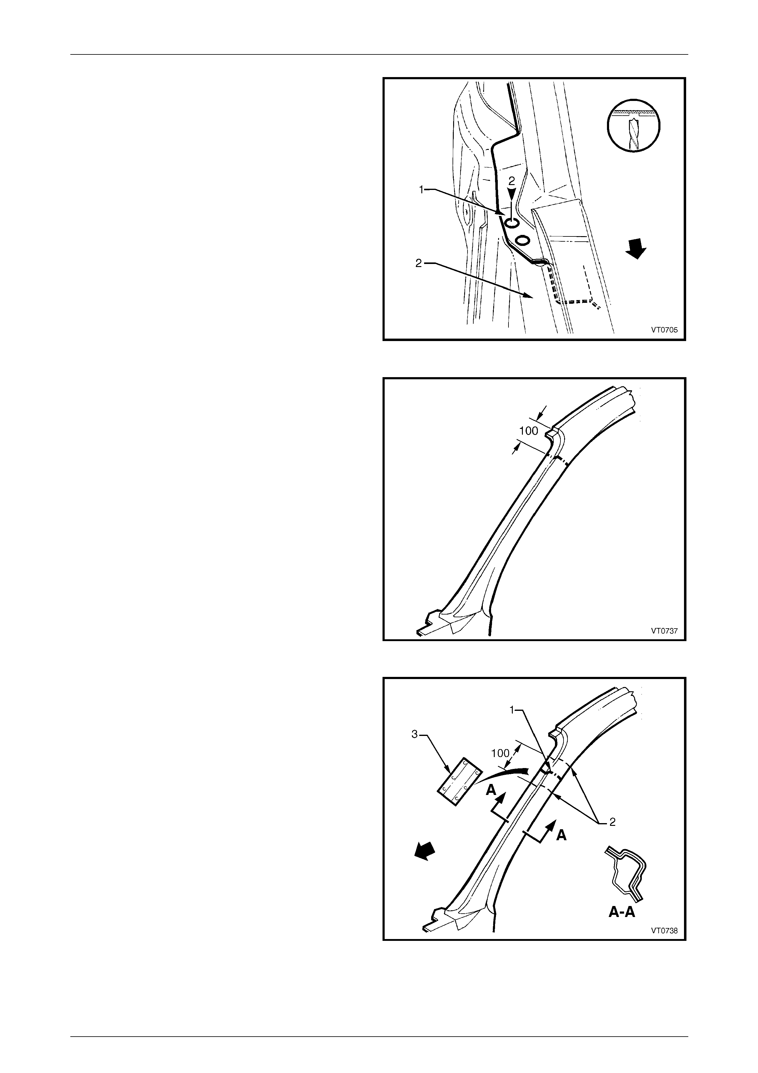
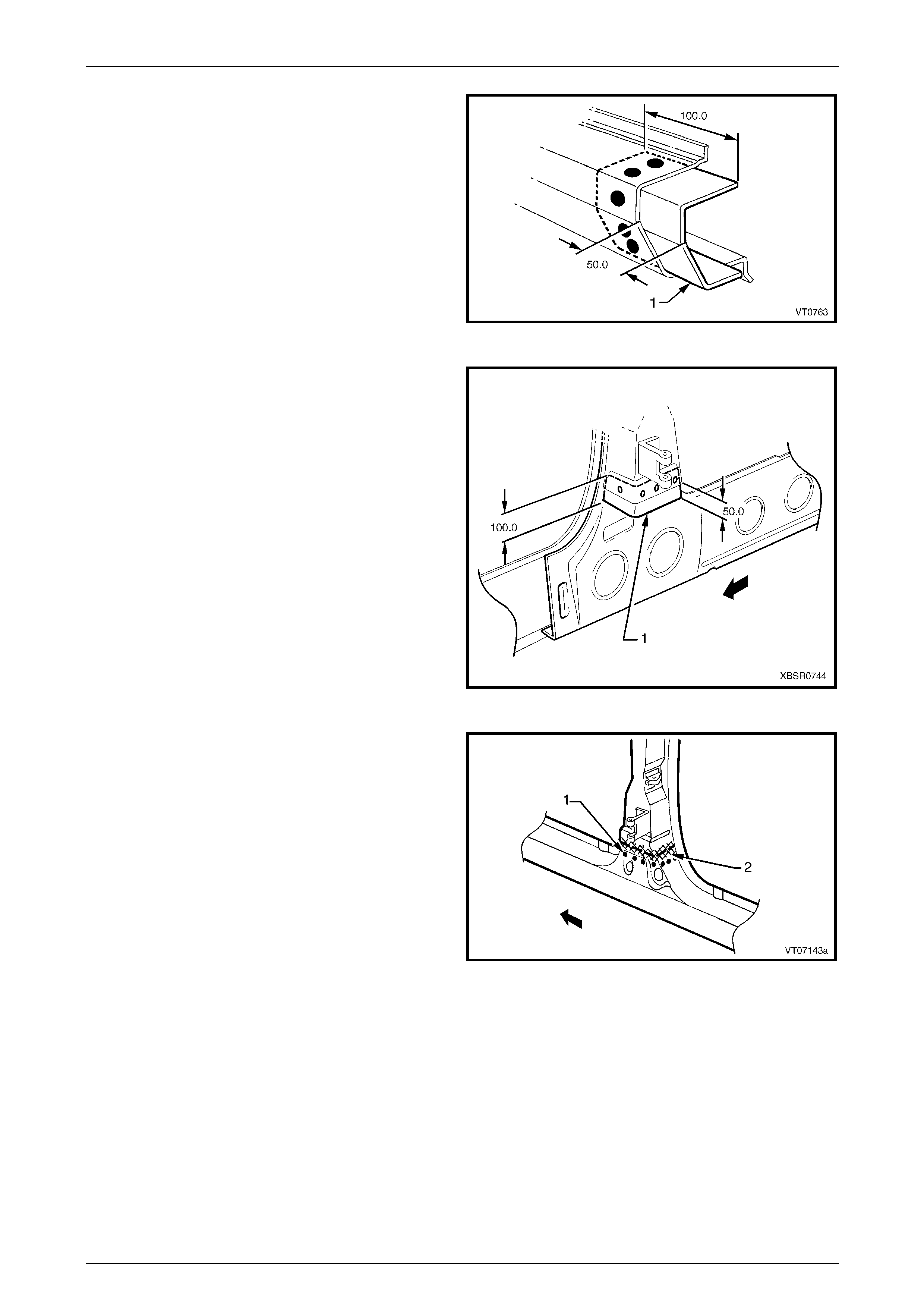
10 Select a cutting point on the hinge pillar. This cut point
should be within the region specified.
Figure 7F – 29
11 At the selected point (1), cut through the outer and
reinforcement panels, leaving the inner panel intact.
12 Mark the inner panel at points 50 mm either side of the
cut line on the outer panel and cut the inner panel at
these two points (2). Spot cut the welds and remove
the 100 mm section of inner panel (3).
Figure 7F – 30
7F Body Side – Crew Cab Page 7F–17
Page 7F–17
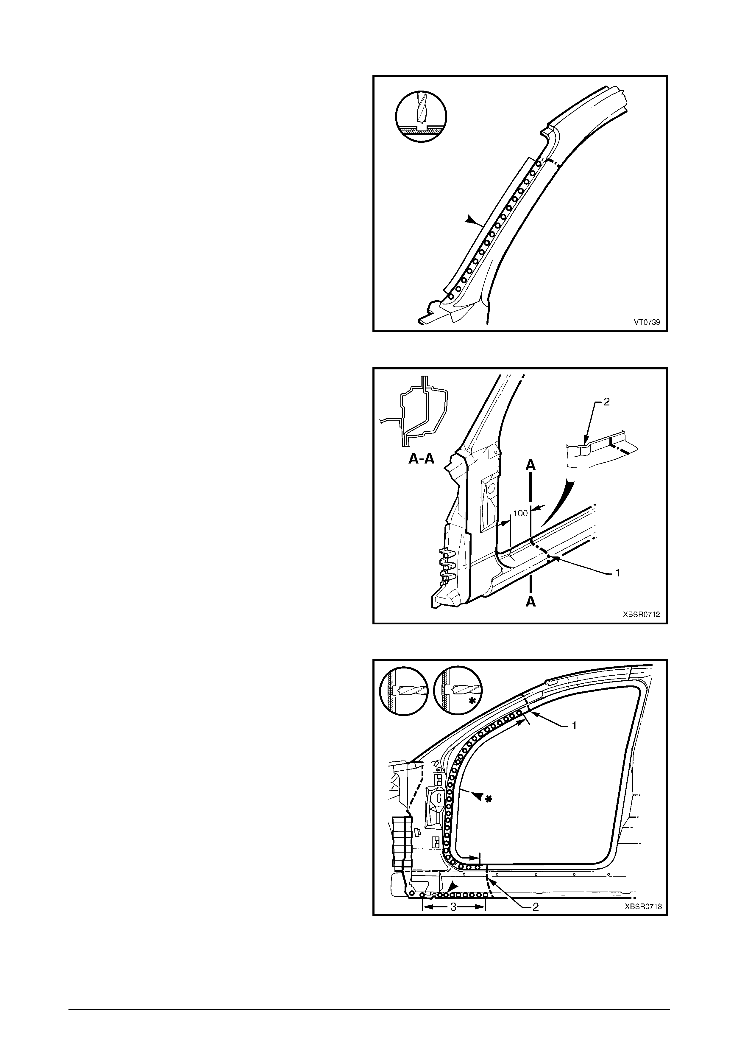
13 Spot cut the welds on the windshield side flange, up to
the point of the cut.
Figure 7F – 31
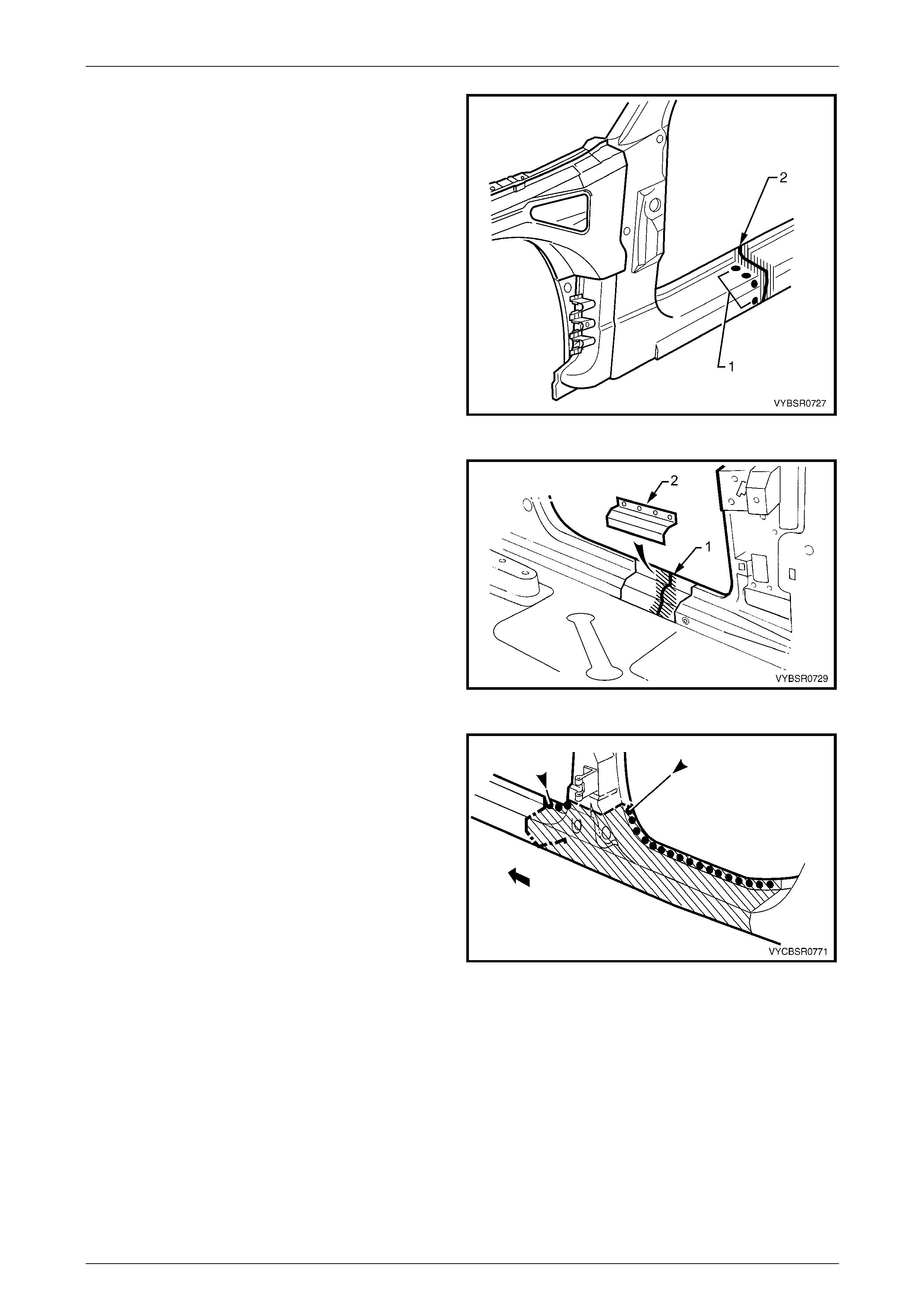
14 Cut through the rocker panel section of the door
opening frame assembly. The cut point (1) sh ould be
approximately 100 mm from the dimple (2) on the
flange. Cut through both the outer pane l and the
reinforcement panel.
Figure 7F – 32
15 Spot cut the welds on the flange along the front door
opening, from the cut near the top of the hinge pill ar
(1) to the cut in the rocker panel (2).
16 Spot cut the welds along the flange (3) below the
rocker panel (to the point of the cut), separ ating the
door opening frame assembly from the inner rocker
panel.
17 Remove the partial hinge p illar from the vehicle, then
repair any damage to adjacent parts.
18 Check and rectify the alignme nt of
the body as required, refer to
Section 3F Body Construction – Crew Cab.
Figure 7F – 33
7F Body Side – Crew Cab Page 7F–18
Page 7F–18
Replace
NOTE
• Spot welding is the preferred method for
attaching of panels and should be used
whenever possible. Where the spot welding
equipment will not access the required weld
position, a plug weld should be performed.
• The same number and position of spot welds
(or plug welds) should be used when
replacing the panel, as was used during
manufacture, in order to maintain the original
structural strength of the vehicle.
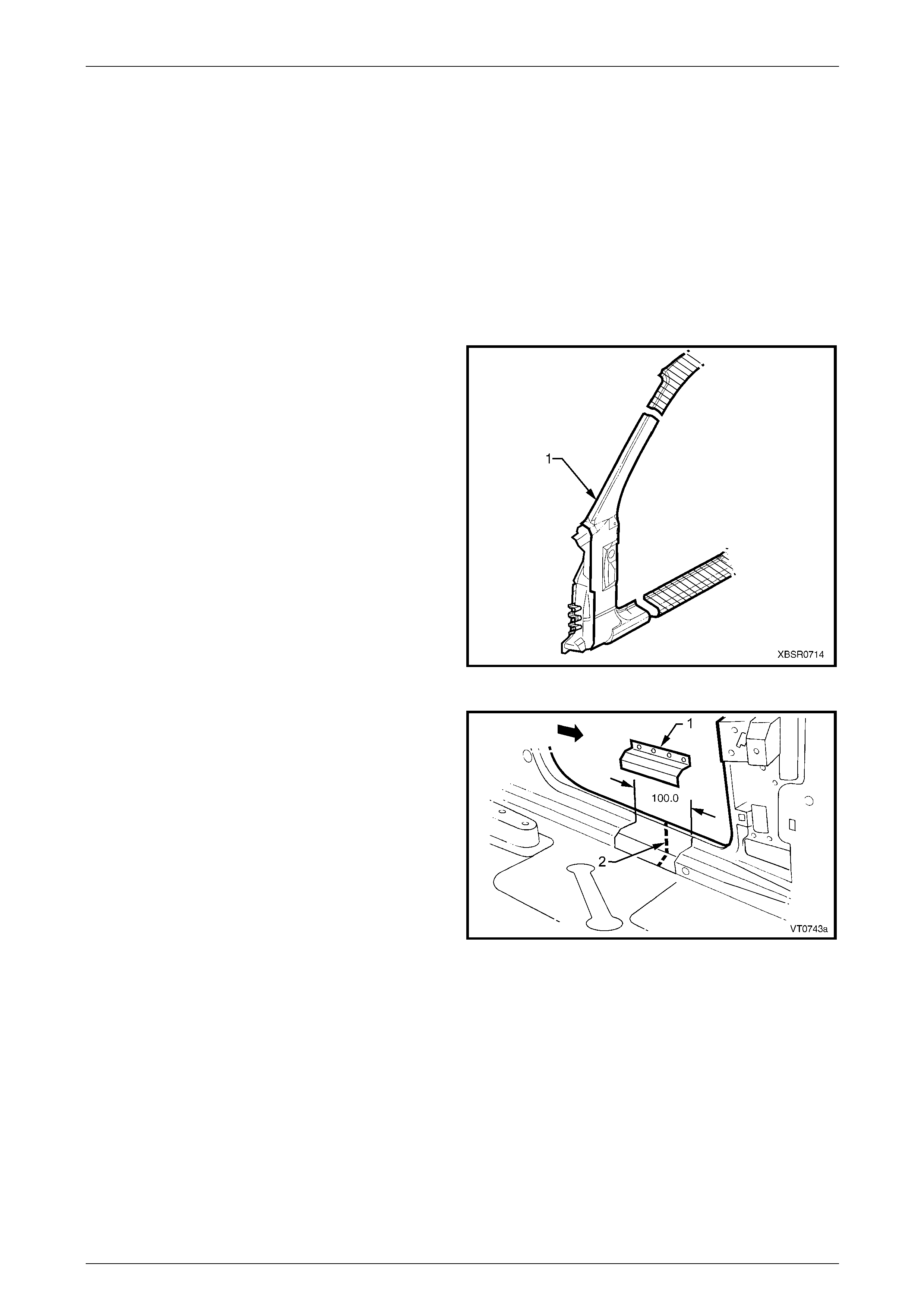
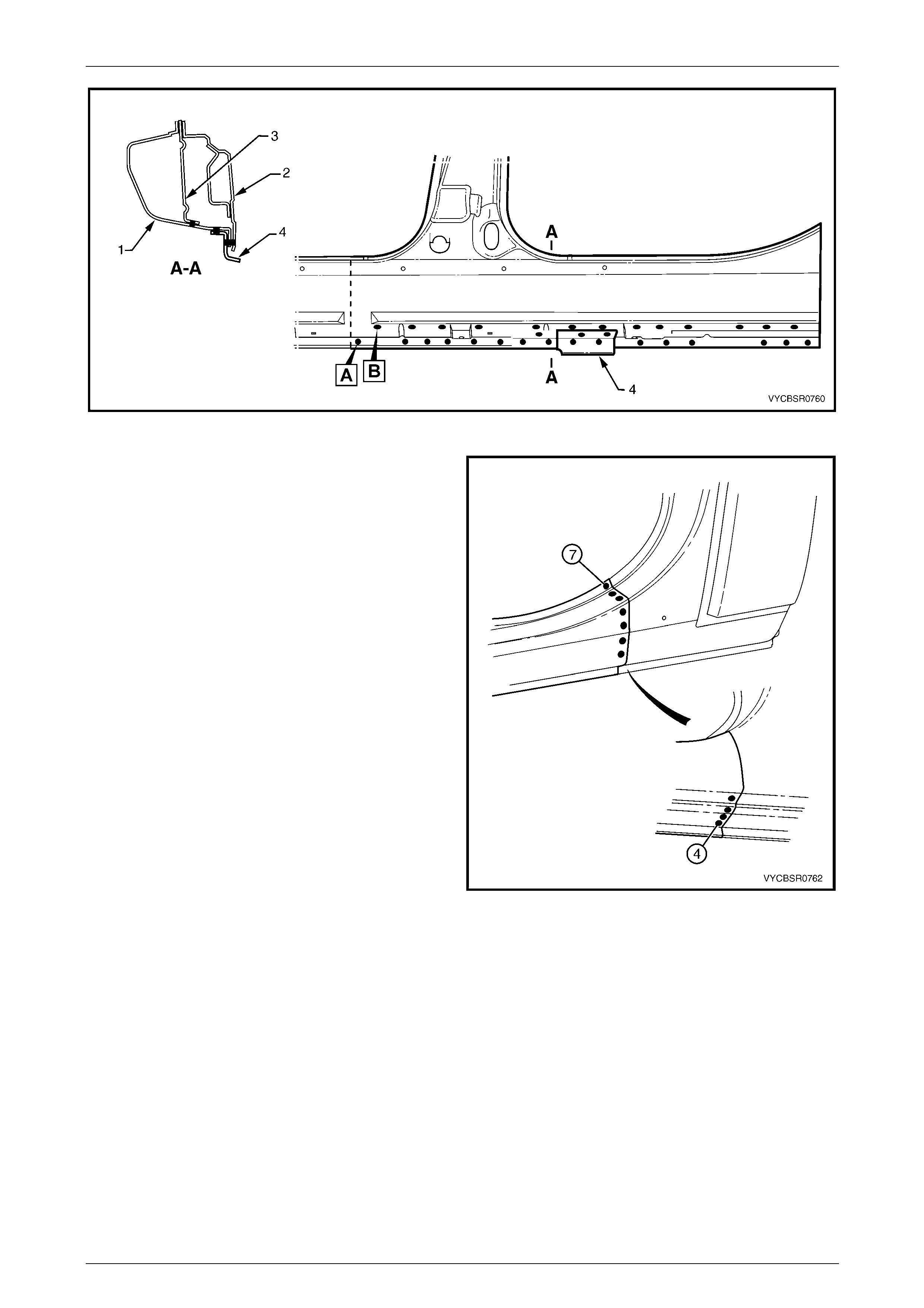
1 Cut a replacement panel section (1), accurately
measuring the position of cuts to match the section
removed.
Figure 7F – 34
2 Remove a section of inner rocker panel (1), cut 50 mm
each side of the cut in the rocker panel (2). This all ows
access for welding the rocker panel reinf orcement.
Figure 7F – 35
7F Body Side – Crew Cab Page 7F–19
Page 7F–19
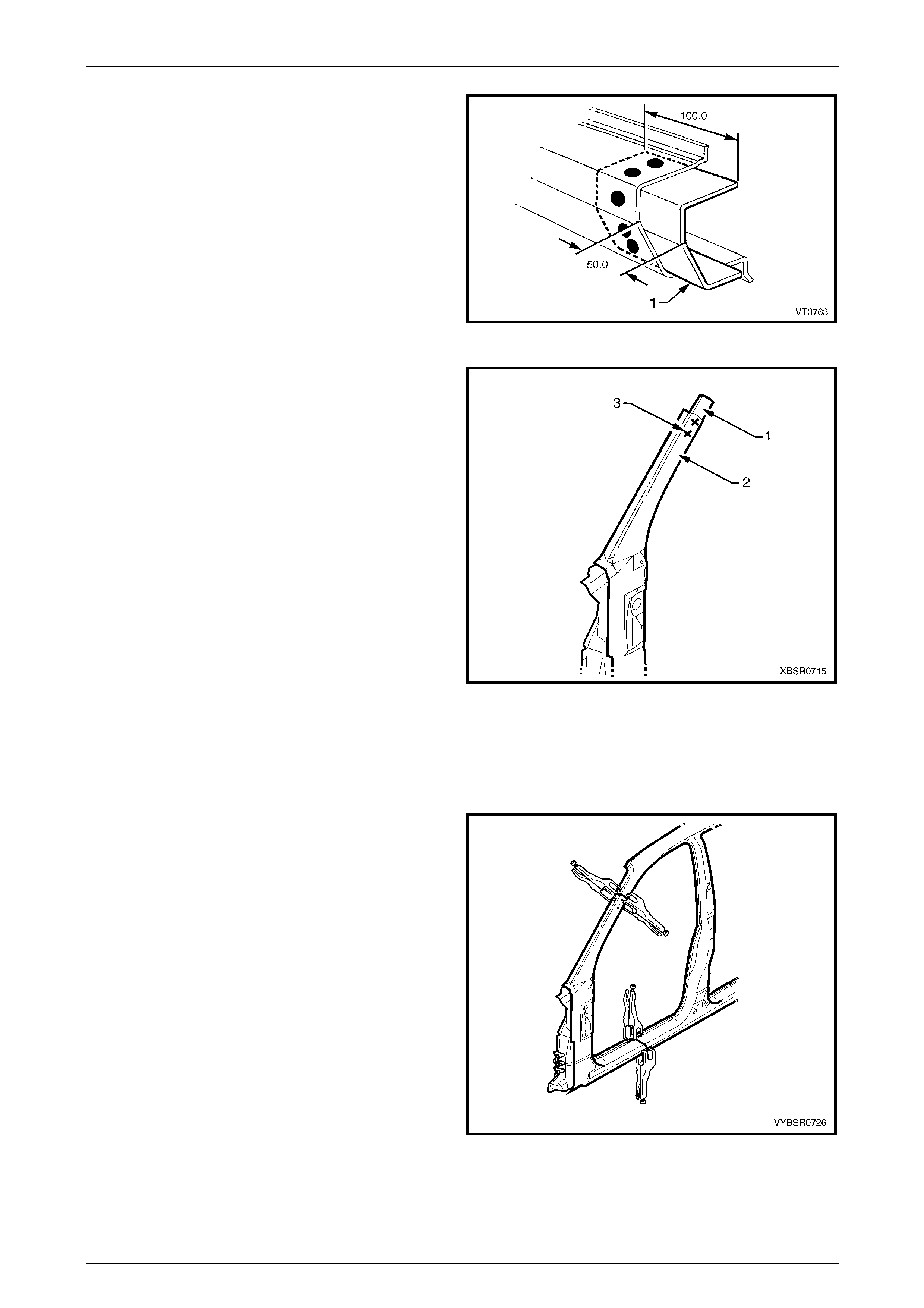
3 Either manufacture a new section or cut an existing
length of surplus rocker panel section, to form a
reinforcement (1), approximately 100 mm in length.
4 Prepare the mating surfaces and treat with Weld
Through Primer (Item 1) as required, refer to
Section 3F Body Construction – Crew Cab.
5 Clamp this reinforcement firmly behind the cut section
of rocker panel on the vehicle and spot or plug weld in
place. Position welds at a maximum spacing of 35 mm
apart.
Figure 7F – 36
6 Using a similar technique, ma nufacture or cut a
section of reinforcement panel (1) (appro xim ately
60 mm long) to fit on the inside of the replacement
hinge pillar out er panel (2) at the point of the cut.
NOTE
Remove the flanges from this reinforcement
panel.
7 Prepare the mating surfaces and treat with Weld
Through Primer (Item 1) as required, refer to
Section 3F Body Construction – Crew Cab.
8 Clamp the reinforcement panel firmly behind the cut
section of the hinge pillar outer and spot weld (3) in
place.
9 Mark the new hinge pillar pan el with drilling locations
in preparation for plug welding where required. Drill
holes as marked.
10 Prepare the mating surfaces and treat with Weld
Through Primer (Item 1) as required, refer to
Section 3F Body Construction – Crew Cab.
11 Apply Acrylic Spot Weld Sealer (Item 2), refer to
Section 3F Body Construction – Crew Cab.
Figure 7F – 37
12 Clamp the replacement panel in position on the
vehicle and check the door opening dimensions,
refer to Section 3F Body Construction – Crew Cab.
Adjust position as required.
Figure 7F – 38
7F Body Side – Crew Cab Page 7F–20
Page 7F–20
13 Plug weld (1) the top of the pillar to the manufactured
reinforcement, then MIG butt weld (2) the two sections
together.
Figure 7F – 39
14 Plug weld (1) the new panel in the rocker panel region,
then MIG butt weld (2) the two sections together.
Figure 7F – 40
15 Gaining access through the removed sectio n of inner
panel, MIG butt weld (1) the reinforcement panel
together.
16 Butt weld the removed access panel (2) in position.
Replace the spot welds with the same number that
was removed.
Figure 7F – 41
7F Body Side – Crew Cab Page 7F–21
Page 7F–21
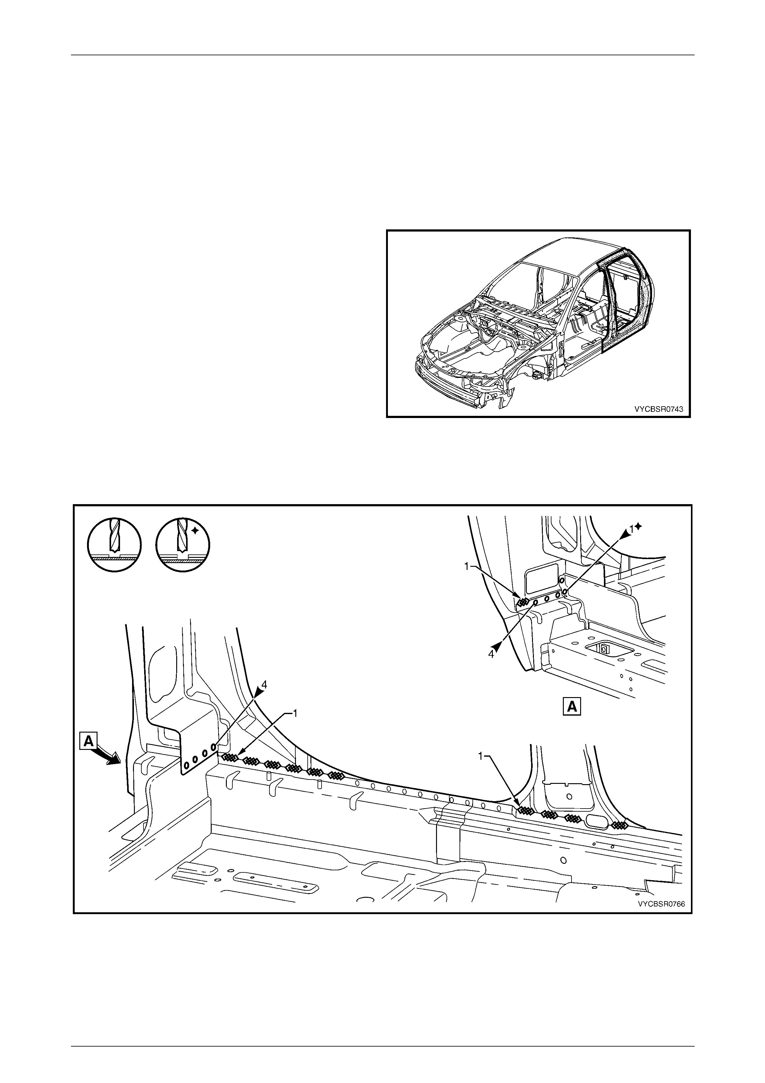
17 Spot weld (1) the pillar along the door op ening flange.
18 Spot weld (2) the flange beneath the rocker pan el,
attaching the new panel to the inner rocker panel.
Figure 7F – 42
19 Spot weld (1) the pillar along the windshield opening
flange.
Figure 7F – 43
20 Spot or plug weld the door opening frame assembly
(1) to the hinge pillar inner panel assembly (2) at the
base of the hinge pillar.
Figure 7F – 44
7F Body Side – Crew Cab Page 7F–22
Page 7F–22
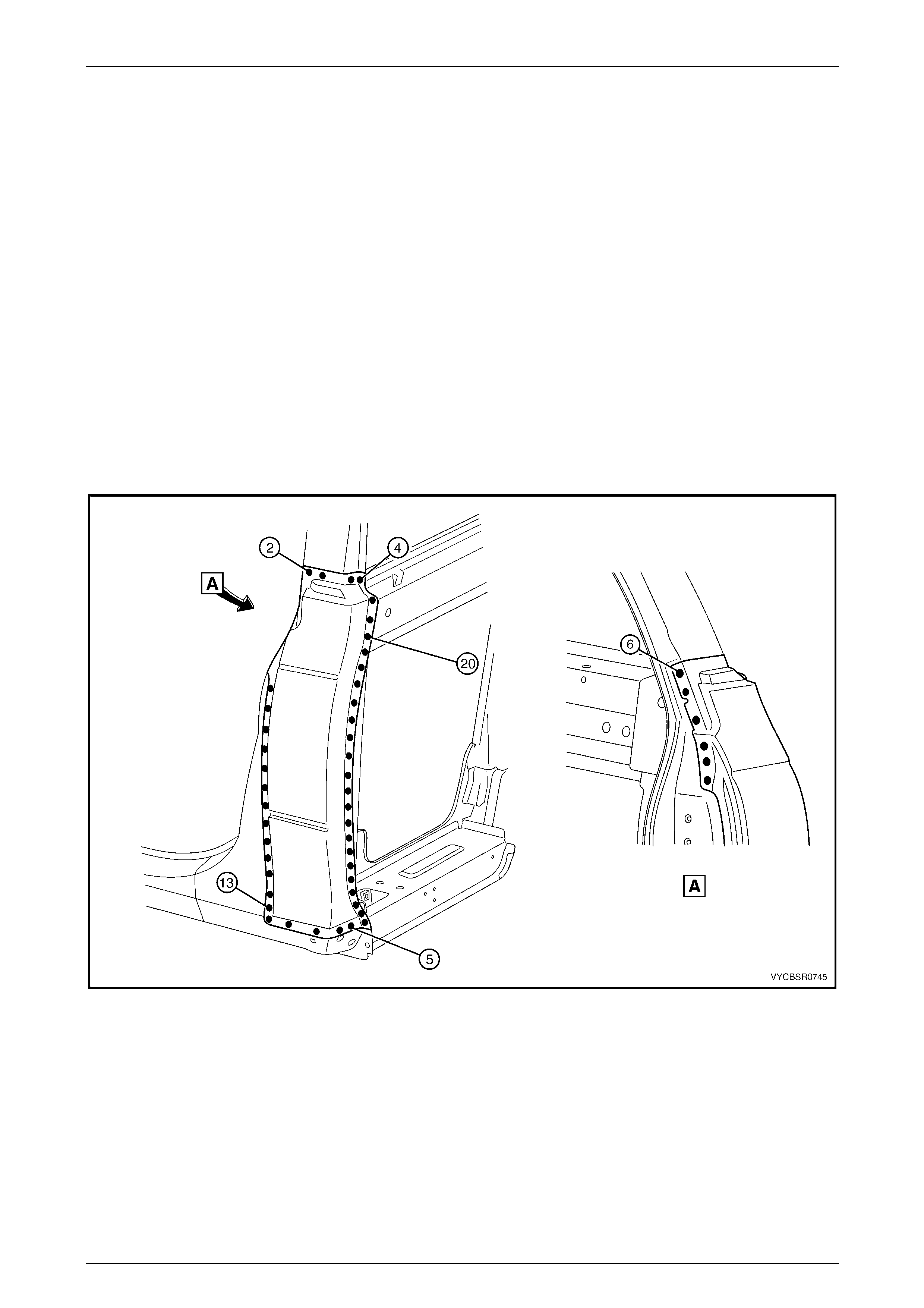
21 Spot or plug weld the door opening frame assembly to
the inner rocker panel and to the hinge pillar inner
panel assembly.
NOTE
If the sheet metal was modified to allow access
to these welds, it should be repaired to its
original configuration.
Figure 7F – 45
22 Gaining access through the section of removed in ner
rocker panel, MIG butt weld (1) the new section of
rocker panel reinforcement to the existing section.
23 Replace the removed section of inner rocker panel (2)
by MIG butt welding it in place and spot welding it
along the door opening flange. Replace the spot welds
with the same number of as were removed.
24 Replace the front wheelhouse panel upper side rail,
refer too Section 4 Front End.
25 Install the front door hinges, refer to
Section 8 Doors, Liftgate and Endgate.
26 Replace the adjoining removed panels as required,
refer to the relevant Section in this Supplement.
27 Refinish and paint panels and other components as
required. Refer to Section 3 Body Construction .
Figure 7F – 46
28 Apply Joint Sealer (Item 3) as required. Refer to Section 3F Body Construction – Crew Cab.
29 Apply Cavity Wax (Item 8) as required to the inside of any box secti ons or areas inaccessible to paint,
refer to Section 3F Body Construction – Crew Cab.
30 Install the dash panel retaining bolt throu gh the hinge pil lar and tighten to the specified torque.
Dash panel retaining b olt
torque specification.........................................35.0 – 45.0 Nm
31 Replace the windshield, refer to Section 1A6 Stationary Windows in the MY 2005 VZ Service Information.
32 Insert Cavity Foam into the hinge pillar as required, refer to Section 2 Precautions.
33 Reinstall the front door assembly, refer to Section 8 Doors, Liftgate and Endgate.
34 Install the remaining components as described in the appropriate Section of the MY 2005 VZ Service Informatio n.
7F Body Side – Crew Cab Page 7F–23
Page 7F–23
2.4 Door Opening Frame Assembly – Partial
Replace, Centre Pillar
Remove
1 Remove the adjacent bolt-on panels a nd components
as described in the appropriate Section of th e MY
2005 VZ Service Information.
2 Remove the rear door assembly, refer to
Section 8 Doors, Liftgate and Endgate.
3 Remove other adjacent pane ls as required, refer to the
relevant Section in this Supplement.
4 Install the vehicle on a suitab le fixture. As a minimum,
support the appropriate structural sections of the
vehicle on safety stands. Secure a suitable tool
between the front door openi ng flanges to maintain
alignment.
Figure 7F – 47
5 Cut through the door opening frame assembly (1) at
the join of the rocker panel reinforcement and centre
pillar reinforcement (2).
NOTE
Make the cut carefully as the rocker panel
reinforcement must not be cut. The centre pillar
reinforcement is removed with the centre pillar
section.
Figure 7F – 48
7F Body Side – Crew Cab Page 7F–24
Page 7F–24
6 Spot cut the welds attaching the lock pillar section to
the centre pillar section of the door op ening frame
assembly.
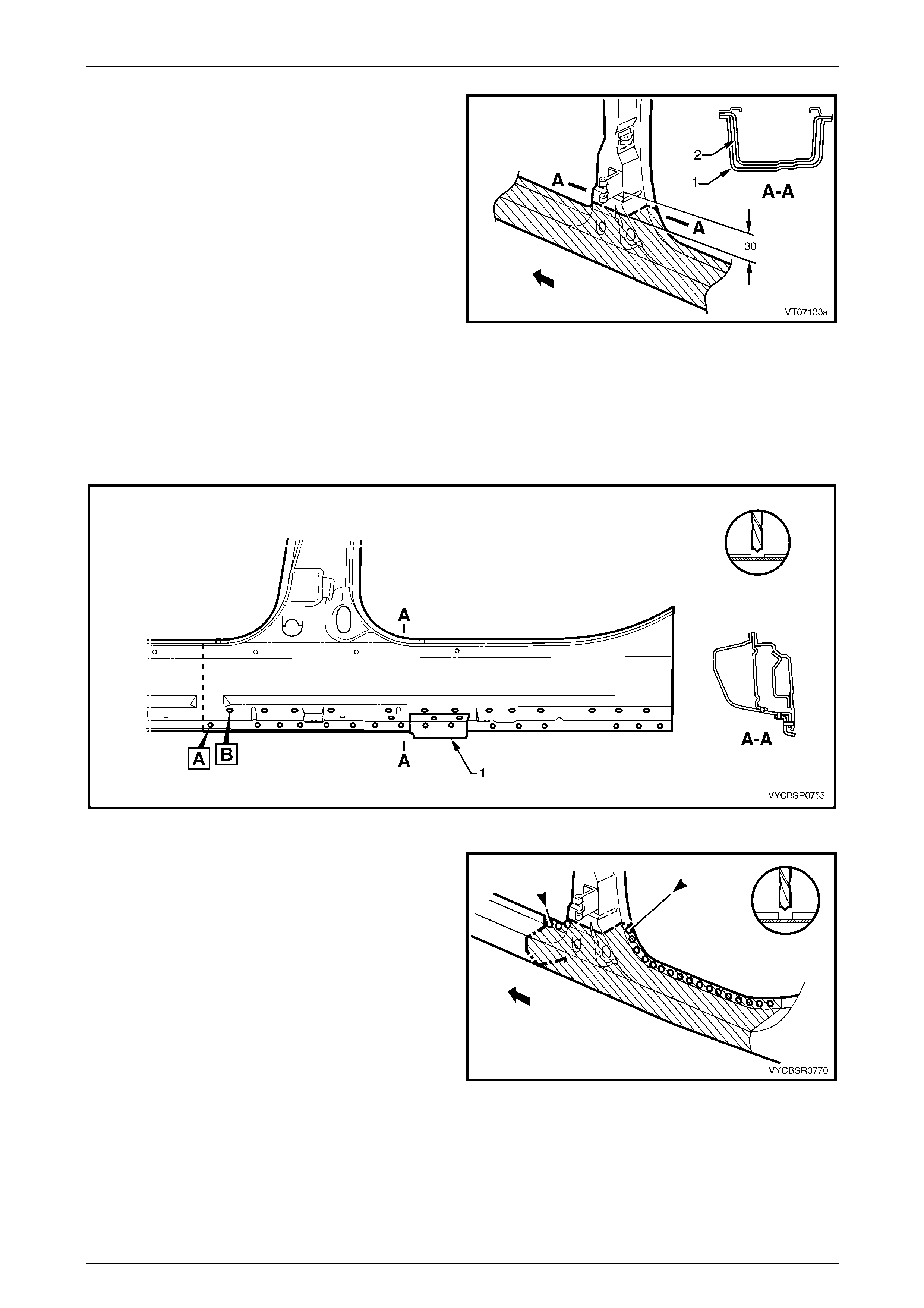
7 Spot cut the welds attaching the underbod y jacking
locator (1) and remove, refer to Figure 7F – 50.
8 Spot cut the welds on the flange attaching the centre
pillar section of the door opening frame assembly to
the inner rocker panel. Refer to weld group A.
9 Spot cut the welds on the underside of the rocker
panel attaching the centre pillar section of the door
opening frame assembly to the quarter panel inner
assembly. Refer to weld group B.
Figure 7F – 49
Figure 7F – 50
10 Cut the door opening frame a ssembly (1) and centre
pillar reinforcement (2) at the intersection point of the
centre pillar upper reinforcement (3). T he intersection
point can be seen by looking at the side of the flange.
NOTE
Do not cut the centre pillar inner reinforcement
assembly (4) and quarter panel inner assembly
(5).
Figure 7F – 51
7F Body Side – Crew Cab Page 7F–25
Page 7F–25
11 Spot cut the welds on the door opening flanges on
both sides of the centre pillar and remove the centre
pillar section from the vehicle.
Figure 7F – 52
12 From the remaining section of centre pillar, carefully
remove enough of the outer skin (1) to expose the
spot welds joining the overlap pin g sections of centre
pillar upper reinforcement (2) and centre pillar
reinforcement (3). NOTE
Do not cut the centre pillar inner reinforcement
assembly (4) and quarter panel inner assembly
(5).
Figure 7F – 53
13 Spot cut as shown, to remove the remaining tongue of
the centre pillar reinforcement. Leave the holes drilled
in reinforcement to facilitate plug welding the
replacement section.
14 Remove the panel from the vehicle, then repair any
damage to adjacent parts.
15 Check and rectify the alignme nt of
the body as required, refer to
Section 3F Body Construction – Crew Cab.
Figure 7F – 54
7F Body Side – Crew Cab Page 7F–26
Page 7F–26
Replace
NOTE
• Spot welding is the preferred method for
attaching of panels and should be used
whenever possible. Where the spot welding
equipment will not access the required weld
position, a plug weld should be performed.
• The same number and position of spot welds
(or plug welds) should be used when
replacing the panel, as was used during
manufacture, in order to maintain the original
structural strength of the vehicle.
1 Cut the replacement panel through rocker section as
shown (1). Accurately measure the position of cuts to
match the removed panel section.
Figure 7F – 55
2 Cut the replacement panel at the top of the centre
pillar (1).
NOTE
Position the cut above the tongue on the centre
pillar reinforcement, which is visible from the
back of the panel.
3 Adjust the cut on the vehicle side of the outer panel so
that it matches the cut on the replacement section.
Figure 7F – 56
4 On the replacement panel, cut along each side and
bend back the outer panel (3). This will expose the
spot welds attaching the remaining piece of upper
reinforcement (1) to the tongue (2) of the centre pillar
reinforcement.
Figure 7F – 57
7F Body Side – Crew Cab Page 7F–27
Page 7F–27
5 Spot cut the nine welds and remove the remaining
section of centre pillar upper reinforc ement (1) from
the replacement panel.
Figure 7F – 58
6 Cut one section from surplus rocker panel, o r
manufacture new a section (1), approximately 100 mm
in length.
7 Prepare the mating surfaces and treat with Weld
Through Primer (Item 1) as required, refer to
Section 3F Body Construction – Crew Cab.
8 Clamp the section firmly behind the cut face of the
rocker panel on the vehicle and spot or plug weld in
place. Perform the welds at a maximum spacing of
35 mm.
9 Mark the new panel with drilling locations in
preparation for plug welding where required. Drill holes
as marked.
10 Prepare all mating surfaces and treat with Weld
Through Primer (Item 1) as required, refer to
Section 3F Body Construction – Crew Cab.
Figure 7F – 59
11 Install the replacement panel i n position, sliding the
tongue of the centre pillar reinforcement (1) behind the
centre pillar upper reinforcement (2).
NOTE
Manipulate the rocker panel section in position,
inserting the front first, then the rear.
12 Clamp the assembly in place and p lug weld the centre
pillar upper reinforcement to the centre pill ar
reinforcement at the upper join.
13 Plug weld the rocker panel section to the
reinforcement section.
14 Spot weld along the door openin g flanges on both
sides of the centre pillar.
Figure 7F – 60
7F Body Side – Crew Cab Page 7F–28
Page 7F–28
15 Fold the outer panel back in position at the top of the
centre pillar. Spot weld along the door flange section
and MIG butt weld the sections together as shown.
16 MIG butt weld the join in the rocker panel.
Figure 7F – 61
17 Plug or spot weld the lock pillar section of the door
opening frame assembly to the centre pillar s ection.
18 Plug weld the flange attaching the centre pil lar section
(1) to the inner rocker panel (2), refer to
Figure 7F – 63. Refer to weld group A.
19 Plug weld on the underside of the rocker panel the
centre pillar section to the quarter panel inner
assembly (3). Refer to weld group B.
20 Plug weld the underbody jacking locator (4) in place.
Figure 7F – 62
7F Body Side – Crew Cab Page 7F–29
Page 7F–29
Figure 7F – 63
21 Install the rear door hinges, refer to Section 8 Doors Liftgate and Endgate.
22 Dress the welds by grinding or sanding, ensuring sufficient material remains to guarantee the strength of the weld.
Finish the area using an appropriate technique.
23 Replace other adjoining removed pa nels as required, refer to the relevant Section in this Supp lement.
24 Refinish and paint panels and other components as required. Refer to Section 3 Body Construction.
25 Apply Joint Sealer (Item 3) as required. Refer to Section 3F Body Construction – Crew Cab.
26 Apply Cavity Wax (Item 8) as required to the inside of any box sections or ar eas inaccessible to paint, refer to
Section 3F Body Construction – Crew Cab.
27 Insert Cavity Foam into the centre pillar as required, refer to Section 2 Precautions.
28 Reinstall the rear door assem bl y, refer to Section 8 Doors Liftgate an d Endgate.
29 Install the remaining components as described in the appropriate Section of the MY 2005 VZ Service Informatio n.
7F Body Side – Crew Cab Page 7F–30
Page 7F–30
2.5 Door Opening Frame Assembly – Partial
Replace, Lock Pillar
Remove
1 Remove the adjacent bolt-on panels a nd components
as described in the appropriate Section of th e MY
2005 VZ Service Information.
2 Remove the rear window assembly, refer to
Section 1A6 Stationary Windows in the MY 2 005 VZ
Service Information.
3 Install the vehicle on a suitab le fixture. As a minimum,
support the appropriate structural sections of the
vehicle on safety stands.
4 Remove rear quarter panel, refer to
2.1 Rear Quarter Panel – Replace.
5 Remove other adjacent pane ls as required, refer to the
relevant Section in this Supplement. Figure 7F – 64
6 Spot cut the welds attaching the lock pillar section of
the door opening frame assembly to the centre pillar
section.
Figure 7F – 65
7F Body Side – Crew Cab Page 7F–31
Page 7F–31
7 Spot cut the welds attaching the lock pillar section of
the door opening frame assembly.
NOTE
Structural adhesive is applied to the C-pillar
reinforcement (1), adhering it to the quarter
panel inner, which will require cutting. Prise the
door opening frame panel and rough-cut the
reinforcement, then grind off the remaining part
once the door opening frame assemb l y has been
removed.
8 Remove the partial door openi ng frame assembly from
the vehicle, then repair any damage to adjacent parts
as required.
9 Check and rectify the alignme nt of
the body as required, refer to
Section 3F Body Construction – Crew Cab.
Figure 7F – 66
Replace
NOTE
• Spot welding is the preferred method for
attaching of panels and should be used
whenever possible. Where the spot welding
equipment will not access the required weld
position, a plug weld should be performed.
• The same number and position of spot welds
(or plug welds) should be used when
replacing the panel, as was used during
manufacture, in order to maintain the original
structural strength of the vehicle.
1 As required, mark the new panel with drilling locations in preparation for plug welding. Drill holes as required.
2 Prepare all mating surfaces and treat with Weld Through Primer (Item 1) as requir ed,
refer to Section 3F Body Construction – Crew Cab.
3 Apply Acrylic Spot Weld Sealer (Item 2), refer to Section 3F Body Construction – Crew Cab.
4 Apply Structural Adhesive (Item 6), refer to Section 3F Body Constructio n – Crew Cab.
7F Body Side – Crew Cab Page 7F–32
Page 7F–32
5 Plug or spot weld the lock pillar section of the door
opening frame assembly to the door openin g frame
assembly.
Figure 7F – 67
6 Plug or spot welds the lock pillar section of the door
opening frame assembly to the centre pillar s ection.
7 Replace the rear quarter panel, refer to
2.1 Rear Quarter Panel – Replace.
8 Replace the adjoining removed panels as required,
refer to the relevant Section in this Supplement.
9 Refinish and paint panels and other components as
required. Refer to Section 3 Body Construction .
10 Apply Joint Sealer (Item 3) as required. Refer to
Section 3F Body Construction – Crew Cab.
11 Apply Cavity Wax (Item 8) as required to the inside of
any box sections or areas inaccessible to paint, refer
Section 3F Body Construction – Crew Cab.
12 Insert Cavity Foam into the lock pillar as required,
refer to Section 2 Precautions.
13 Replace the rear window assembly, refer to
Section 1A6 Stationary Windows in the MY 2 005 VZ
Service Information.
14 Install the remaining components as described in the
appropriate Section of the MY 2005 VZ Servic e
Information.
Figure 7F – 68
7F Body Side – Crew Cab Page 7F–33
Page 7F–33
2.6 Door Opening Frame Assembly – Partial
Replace, Rocker Panel
NOTE
This procedure details the replacement of the
rocker panel section of the door opening frame
assembly.
NOTE
As there are several critical reinforc ements in the
lower hinge pillar area, the rocker panel section
must not be cut forward of the area shown. If the
rocker panel is damaged forward of this area,
replace the rocker panel and partial hinge pillar
as one section. Modify this procedure
accordingly, also referring to 2.5 Door Opening
Frame Assembly – Partial Replace, Lock Pillar.
Remove
1 Remove the adjacent bolt-on panels a nd components
as described in the appropriate Section of th e MY
2005 VZ Service Information.
2 Secure the vehicle on a suitable fixture. As a
minimum, support the appropriate structural s ections
of the vehicle on safety stands. Install suitable bracing
in the vehicle to ensure the correct body alignment is
maintained when the rocker pane l section is removed.
3 Remove other adjacent pane ls as required, refer to the
relevant Section in this Supplement.
Figure 7F – 69
4 Cut through the rocker panel section of the door
opening frame assembly. The cut point (1) must not be
further forward than the third rocker panel m oulding
attaching hole (2). Cut through both the outer panel
and the reinforcement.
Figure 7F – 70
7F Body Side – Crew Cab Page 7F–34
Page 7F–34
5 Using a suitable cutting tool, cut through the centre
pillar at a position 30 mm below the lower edge of the
door hinge. Cut through both the door opening frame
assembly (1) and centre pillar reinforcement (2).
Figure 7F – 71
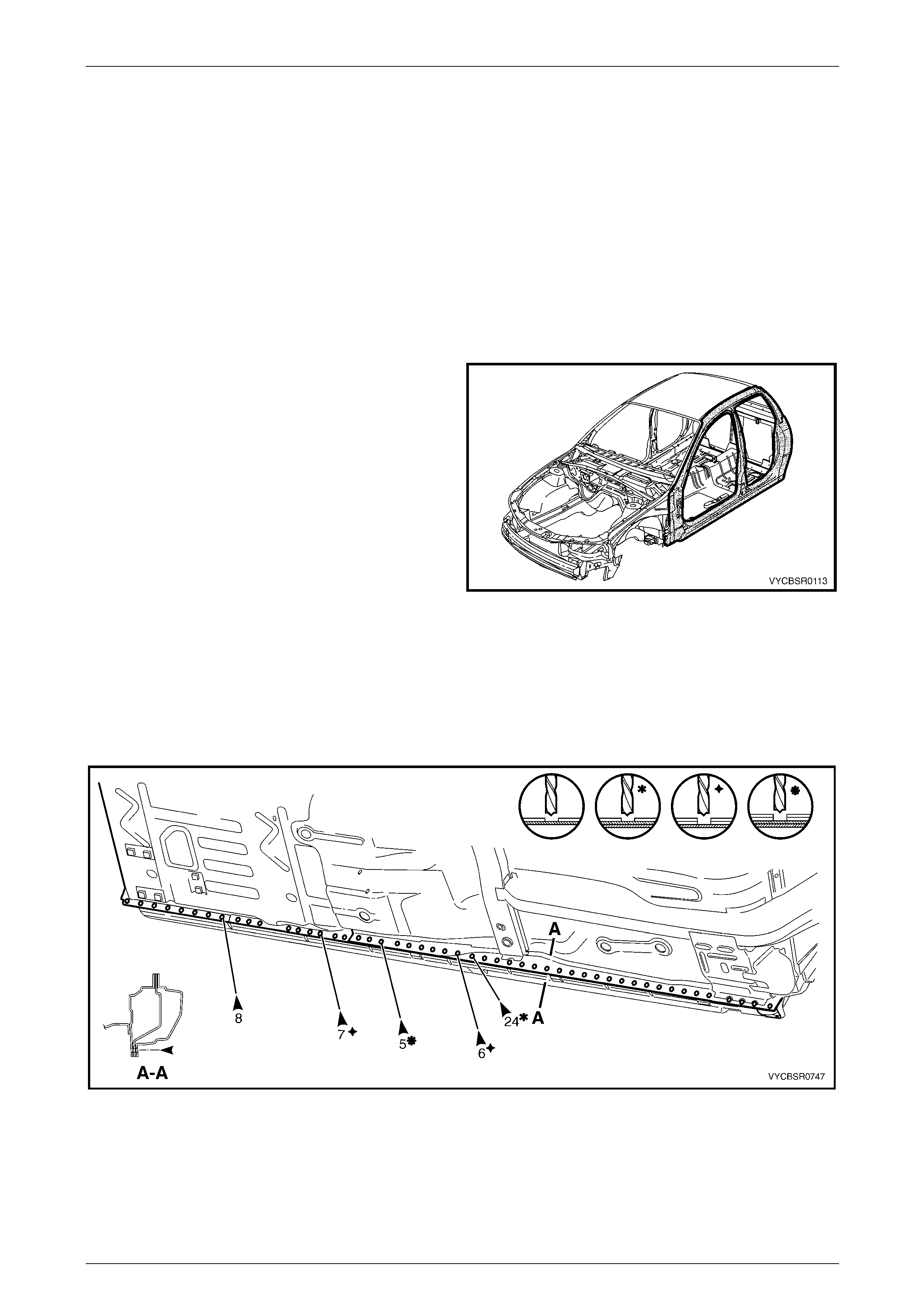
6 Spot cut the welds attaching the underbody jacking locator (1) and remove, refer to F igure 7F – 72.
7 Spot cut the welds on the flange attaching the rocker panel as required, to separate the ro cker panel from the inner
rocker panel. Refer to weld group A.
8 Spot cut the welds on the underside of the rocker panel as required to separate the rocker pane l from the quarter
panel inner assembly. Refer to weld group B.
Figure 7F – 72
9 Spot cut the welds along the lower edge of the front
and rear door openings as required, to complete the
detachment of the rocker panel section.
Figure 7F – 73
7F Body Side – Crew Cab Page 7F–35
Page 7F–35
10 Spot cut the welds attaching the lock pillar section of
the door opening frame assembly to the centre pillar.
NOTE
Structural adhesive is applied to the lock pillar
panel. Care is required when removing the
section of the centre pillar attached to the lock
pillar.
11 Remove the panel from the vehicle, then repair any
damage to adjacent parts.
12 Check and rectify the alignme nt of
the body as required, refer to
Section 3F Body Construction – Crew Cab.
Figure 7F – 74
Replace
NOTE
• Spot welding is the preferred method for
attaching of panels and should be used
whenever possible. Where the spot welding
equipment will not access the required weld
position, a plug weld should be performed.
• The same number and position of spot welds
(or plug welds) should be used when
replacing the panel, as was used during
manufacture, in order to maintain the original
structural strength of the vehicle.
1 Cut a new replacement rocker panel section.
Accurately measure the position of the cuts on the
removed section.
2 Remove a section of inner rocker panel (1), cut 50 mm
each side of the cut in the rocker panel. This allows
access for welding the rocker panel reinf orcement.
Figure 7F – 75
7F Body Side – Crew Cab Page 7F–36
Page 7F–36
3 Manufacture or cut a reinforcement (1) (appr oximately
100 mm long) to fit on the inside of the existing rocker
panel at the point of the cut.
4 Prepare the mating surfaces and treat with Weld
Through Primer (Item 1) as required, refer to
Section 3F Body Construction – Crew Cab.
5 Clamp the manufactured reinforcement firmly to the
inside of the rocker panel section of the d oor opening
frame assembly on the vehicle and plug weld in
position. Position welds at a maximum sp acing of
35 mm.
Figure 7F – 76
6 Manufacture or cut a reinforcement (1) (appr oximately
100 mm long) to fit inside of the existing centre pillar
section at the point of the cut.
7 Prepare the mating surfaces and treat with Weld
Through Primer (Item 1) as required, refer to
Section 3F Body Construction – Crew Cab.
8 Clamp the manufactured reinforcement panel firmly to
the inside of the outer panel of the door opening frame
assembly on the vehicle and p lug weld in position.
Position welds at a maximum spacing of 35 mm.
NOTE
The outer panel will be plug welded from the
outer side of the vehicle, while the rocker panel
and centre pillar reinforcements will be butt
welded from the inner side of the vehicle.
Figure 7F – 77
9 Install the replacement section onto the vehicl e by
sliding the front and centre pillar sections o nto the
reinforcements, while lifting the rear into posi tion.
10 Clamp the panel in position.
11 Weld the new section to the centre pillar by plug
welding (1).
12 MIG butt weld the centre pillar reinforcement from
inside the centre pillar, through the large ho le in the
inner panel immediately behind the weld.
13 Finish the centre pillar attachment by MIG welding (2)
along the join of the outer panel.
Figure 7F – 78
7F Body Side – Crew Cab Page 7F–37
Page 7F–37
14 Plug weld (1) the replacement section at the front join,
then MIG butt weld (2) the two sections together.
Figure 7F – 79
15 Gaining access through the section of removed floor
side panel, MIG butt weld (1) the new section of rocker
panel reinforcement to the existing section.
16 Replace the removed section of floor side panel (2) by
MIG butt welding it in place and spot welding it along
the door opening flange. Repl ace the spot welds with
the same number as were removed.
Figure 7F – 80
17 Spot or plug weld the flanges of the front and rear door
openings as required.
NOTE
Use the same number and position of welds as
removed during removal.
18 Plug weld the flange attaching the centre pil lar section
(1) to the inner rocker panel (2), refer to
Figure 7F – 82. Refer to weld group A.
19 Plug weld on the underside of the rocker panel the
centre pillar section to the quarter panel inner
assembly (3). Refer to weld group B.
20 Plug weld the underbody jacking locator (4) in place. Figure 7F – 81
7F Body Side – Crew Cab Page 7F–38
Page 7F–38
Figure 7F – 82
21 Plug or spot welds the lock pillar section to the centre
pillar section.
22 Replace rear quarter panel, refer to
2.1 Rear Quarter Panel – Replace.
23 Replace other adjoining removed pa nels as required,
refer to the relevant Section in this Supplement.
24 Refinish and paint panels and
other components as required.
Refer to Section 3F Body Construction – Crew Cab.
25 Apply Joint Sealer (Item 3) as required.
Refer to Section 3F Body Construction – Crew Cab.
26 Apply Cavity Wax (Item 8) as required to the inside of
any box sections or areas inaccessible to paint,
refer to Section 3F Body Construction – Crew Cab.
27 Insert Cavity Foam into the lock pillar as required,
refer to Section 2 Precautions.
28 Install the remaining components as described in the
appropriate Section of the MY 2005 VZ Servic e
Information.
Figure 7F – 83
7F Body Side – Crew Cab Page 7F–39
Page 7F–39
2.7 Quarter Panel Inner Assembly – Replace
NOTE
This procedure also includes the rear
wheelhouse bracket and rear wheelhouse outer
extension (righ t-hand side only).
Remove
1 Remove the adjacent bolt-on panels a nd components
as described in the appropriate Section of th e MY
2005 VZ Service Information.
2 Remove the rear quarter panel, refer to
2.1 Rear Quarter Panel – Replace.
3 Remove the door opening frame assembly, refer to
2.2 Door Opening Frame Assembly – Repl ace.
4 Remove the adjacent panels as required, refer to the
relevant Section in this Supplement.
5 As required, spot cut the welds attaching the quarter
panel inner assembly to the rear lower body panel and
the inner rocker panel assembly,
refer to Figure 7F – 85.
6 Grind the MIG welds (1), three places, attaching the
quarter panel inner assembly to the inner rocker panel
assembly.
Figure 7F – 84
Figure 7F – 85
7F Body Side – Crew Cab Page 7F–40
Page 7F–40
7 Spot cut the welds attaching the quarter panel inner assembly to the rear body upper inn er pan el assembly,
refer to Figure 7F – 86.
8 Grind the MIG weld (1) attaching the quarter panel inner assembly to the rear body upp er outer pa nel assembly.
Figure 7F – 86
9 Using a cutting tool such as an air chisel or a ngle
grinder, cut through the rear roof outer head er panel
along the side of the quarter pane l inner assembly.
10 Using an angle grind er, air chisel or other suitable tool,
remove the remaining strip of roof header panel from
the quarter panel inner assembl y, along with the
adhesive beneath the strip.
Figure 7F – 87
7F Body Side – Crew Cab Page 7F–41
Page 7F–41
11 Spot cut the welds attaching the quarter panel inner
assembly to the roof rear inner header panel.
Figure 7F – 88
12 Spot cut the welds attaching the quarter panel inner
assembly to the hinge pillar inner panel and the roof
bow panel.
13 Remove the panel from the vehicle, then repair any
damage to adjacent parts.
14 Check and rectify the alignme nt of
the body as required, refer to
Section 3F Body Construction – Crew Cab.
Figure 7F – 89
Replace
NOTE
• Spot welding is the preferred method for
attaching of panels and should be used
whenever possible. Where the spot welding
equipment will not access the required weld
position, a plug weld should be performed.
• The same number and position of spot welds
(or plug welds) should be used when
replacing the panel, as was used during
manufacture, in order to maintain the original
structural strength of the vehicle.
1 Mark the new panel and drill holes in preparation for plug welding where required.
2 Prepare all mating surfaces and treat with Weld Through Primer (Item 1) as required,
refer to Section 3F Body Construction – Crew Cab.
3 Apply Structural Adhesive (Item 6), refer to Section 3F Body Constructio n – Crew Cab.
4 Clamp the new panel in position on the vehicle.
7F Body Side – Crew Cab Page 7F–42
Page 7F–42
5 Plug or spot weld the quarter panel inner assembly to
the hinge pillar inner panel and the roof bow panel.
Figure 7F – 90
6 Plug or spot weld on each side of the vehicle to attach
the quarter panel inner assembly to the roof rear outer
header panel.
7 Plug or spot weld the quarter panel inner assembly to
the rear lower body pan el and the inner rocker panel
assembly, refer to Figure 7F – 92.
8 MIG weld (1), three places, the quarter panel inner
assembly to the inner rocker panel assembly.
Figure 7F – 91
7F Body Side – Crew Cab Page 7F–43
Page 7F–43
Figure 7F – 92
9 Plug or spot weld the quarter panel inner assembly to
the roof rear header inner panel.
10 Plug or spot weld the quarter panel inner assembly to
the rear body upper outer panel an d the rear body
upper inner panel assembly, refer to Figure 7F – 94.
11 MIG weld two places (1) across the quarter panel
inner assembly to the rear body upper outer panel
assembly.
Figure 7F – 93
7F Body Side – Crew Cab Page 7F–44
Page 7F–44
Figure 7F – 94
12 Clean up welds and prime any bare metal.
13 Replace the door opening fra m e assembly, refer to 2.2 Door Opening Frame Assembly – Replace.
14 Replace rear quarter panel, refer to 2.1 Rear Quarter Panel – Replace.
15 Replace the adjoining removed panels as required, refer to the relevant Section in this Supplement.
16 Refinish and paint panels and other components as required. Refer to Section 3 Body Construction.
17 Apply Joint Sealer (Item 3) as required. Refer to Section 3F Body Construction – Crew Cab.
18 Apply Cavity Wax (Item 8) as required to the inside of any box sections or ar eas inaccessible to paint, refer to
Section 3F Body Construction – Crew Cab.
19 Apply Spray-on Deadener (Item 7) to the wheel side of the rear wheelhouse,
refer to Section 3F Body Construction – Crew Cab.
20 Install the remaining components as described in the appropriate Section of the MY 2005 VZ Service Information.