7G Body Side – AWD Wagon Page 7–1
Page 7–1
Section 7G
Body Side – AWD Wagon
ATTENTION
Before performing any service operation or other procedure described in this Section, refer to Section 2
Precautions in this Supplement and Section 00 Warnings, Cautions and Notes in the MY2005 VZ Service
Information for correct workshop practices with regard to safety and/or property damage.
The structure of the body shell has been
developed using complex design and
development techniques. In addition to
meeting all required standards, the vehicle
body is also a critical part of the overall safety
systems. It is therefore imperative the repair
procedures described here are adhered to
during all vehicle body repairs.
1 General Information ...............................................................................................................................2
1.1 Body Side Components ........................................................................................................................................ 2
2 Service Operations.................................................................................................................................4
2.1 Rear Quarter Panel – Replace............................................................................................................................... 4
Remove................................................................................................................................................................... 5
Replace................................................................................................................................................................... 7
2.2 Door Opening Frame Assembly – Replace.......................................................................................................... 9
Remove................................................................................................................................................................... 9
Replace................................................................................................................................................................. 14
2.3 Door Opening Frame Assembly – Partial Replace, Lock Pillar........................................................................ 19
Remove................................................................................................................................................................. 19
Replace................................................................................................................................................................. 21
7G Body Side – AWD Wagon Page 7–2
Page 7–2
1 General Information
With the following exceptions, AWD Wagon Body Side information carries over from Wagon vehicles. For information not
contained within this Section, refer to Section 7B Body Side – Wagon.
• Body side components
• Rear quarter panel
• Door opening frame assembl y
• Door opening frame assembl y lock pillar partial replacement
The rear wheelhouse has been modified to accommodate a larger wheel clearance and attachment of the wheelhouse
opening flare. As such, this Section describe s the replacement procedures for the unique body side components where
the procedures differ from Wagon vehicl es. Removal of bolt-on panels and mechanical compo nents is not covered.
When repairing the body side of the vehicle, care must be taken to ensure the structure is returned to its original
production configuration. This is especially important to maintain side impact standards and for the veh icle’s occupant
protection system to operate correctly.
NOTE
• A sunroof option is available that is fitted on
the production line. To cater for this option, a
stainless steel front drain tube is also fitted
within the hinge pillar cavity, therefore the
partial replacement procedure for the hinge
pillar must not be performed on these
vehicles.
• It is imperative the correct body adhesives,
sealers, deadeners and cavity waxes are
used when repairing th e body structure. Refer
to Section 3G Body Construction – AWD
Wagon.
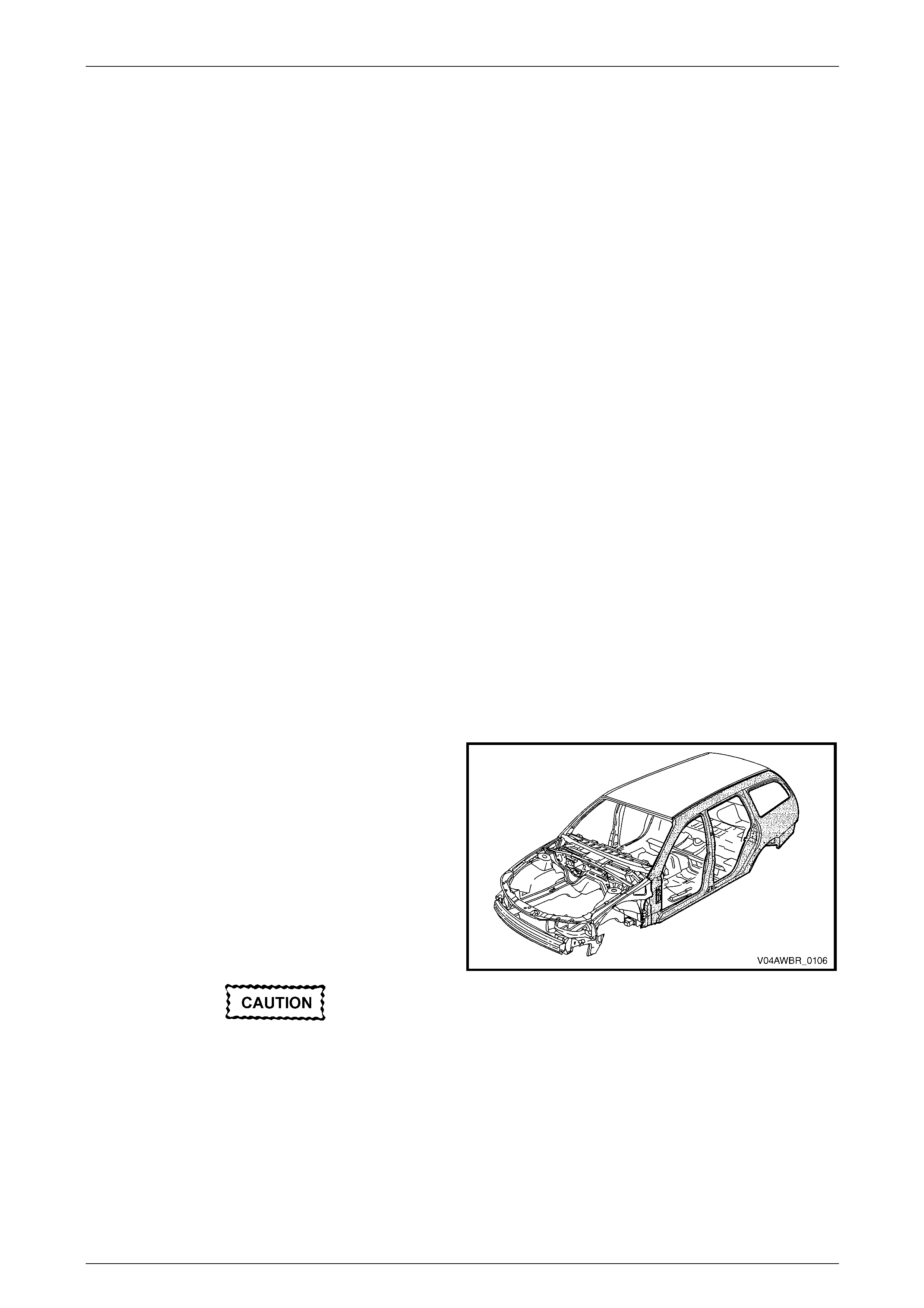
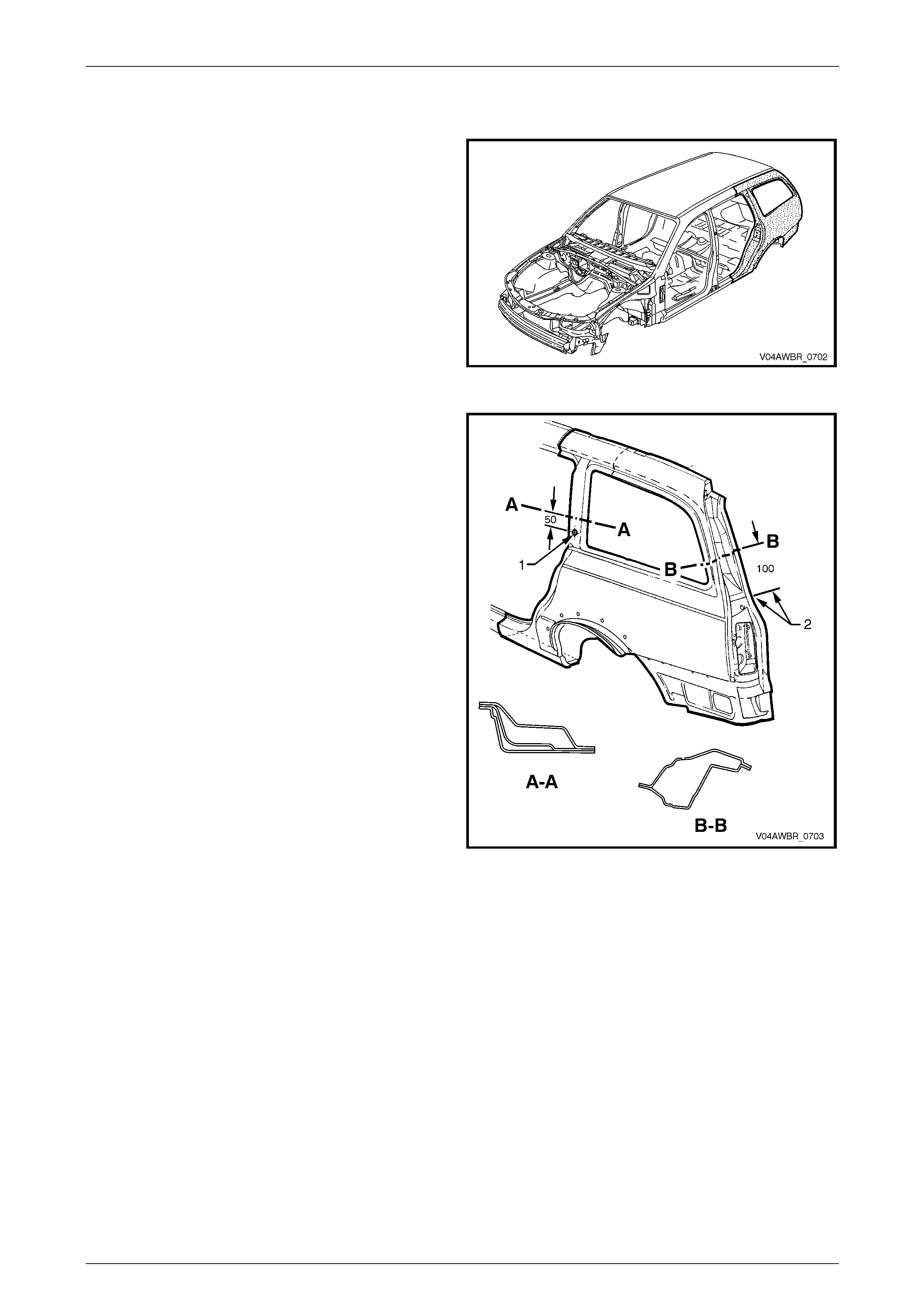
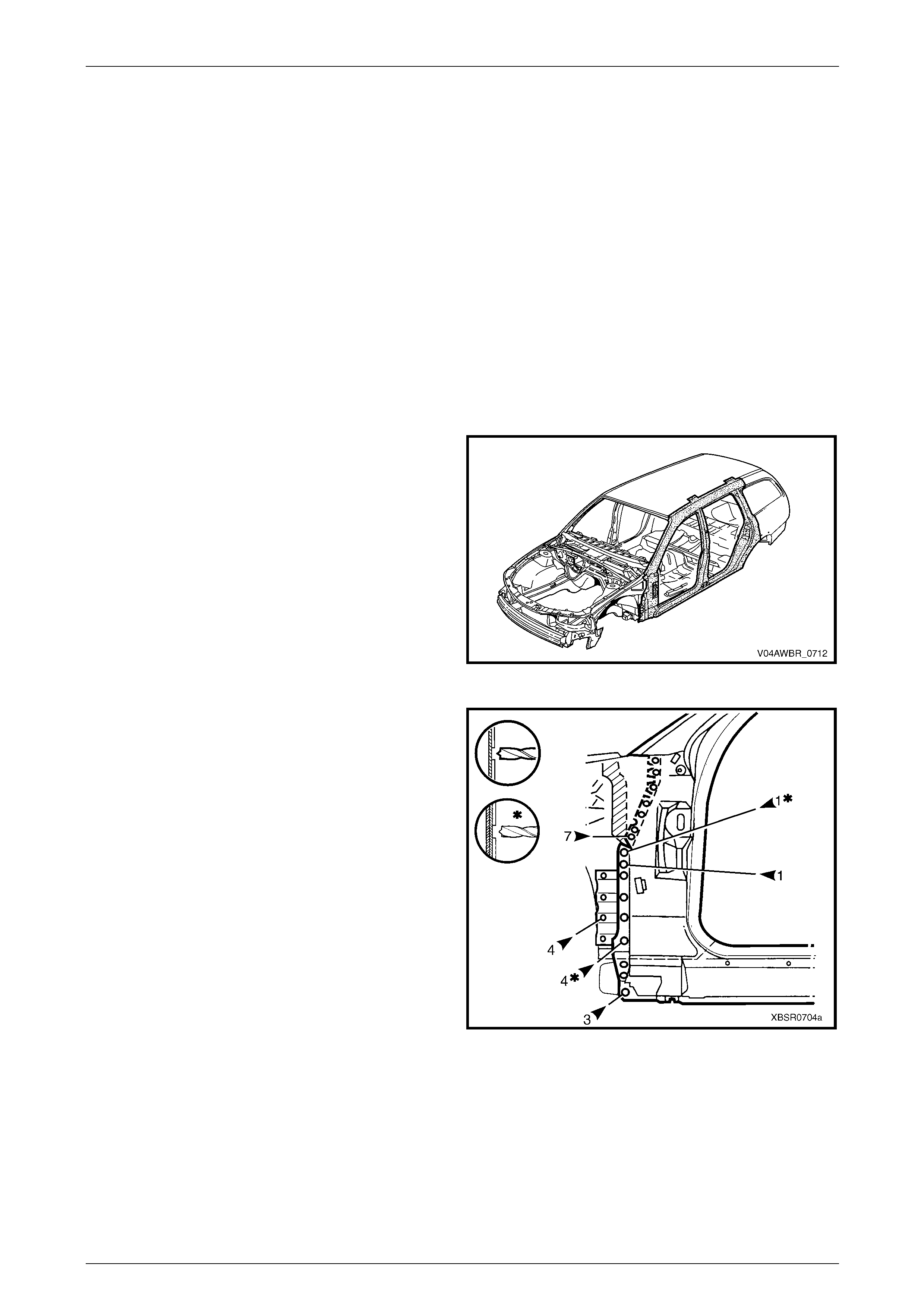
1.1 Body Side Components
The shaded components in Figure 7G – 1 are those dealt
with in this Section.
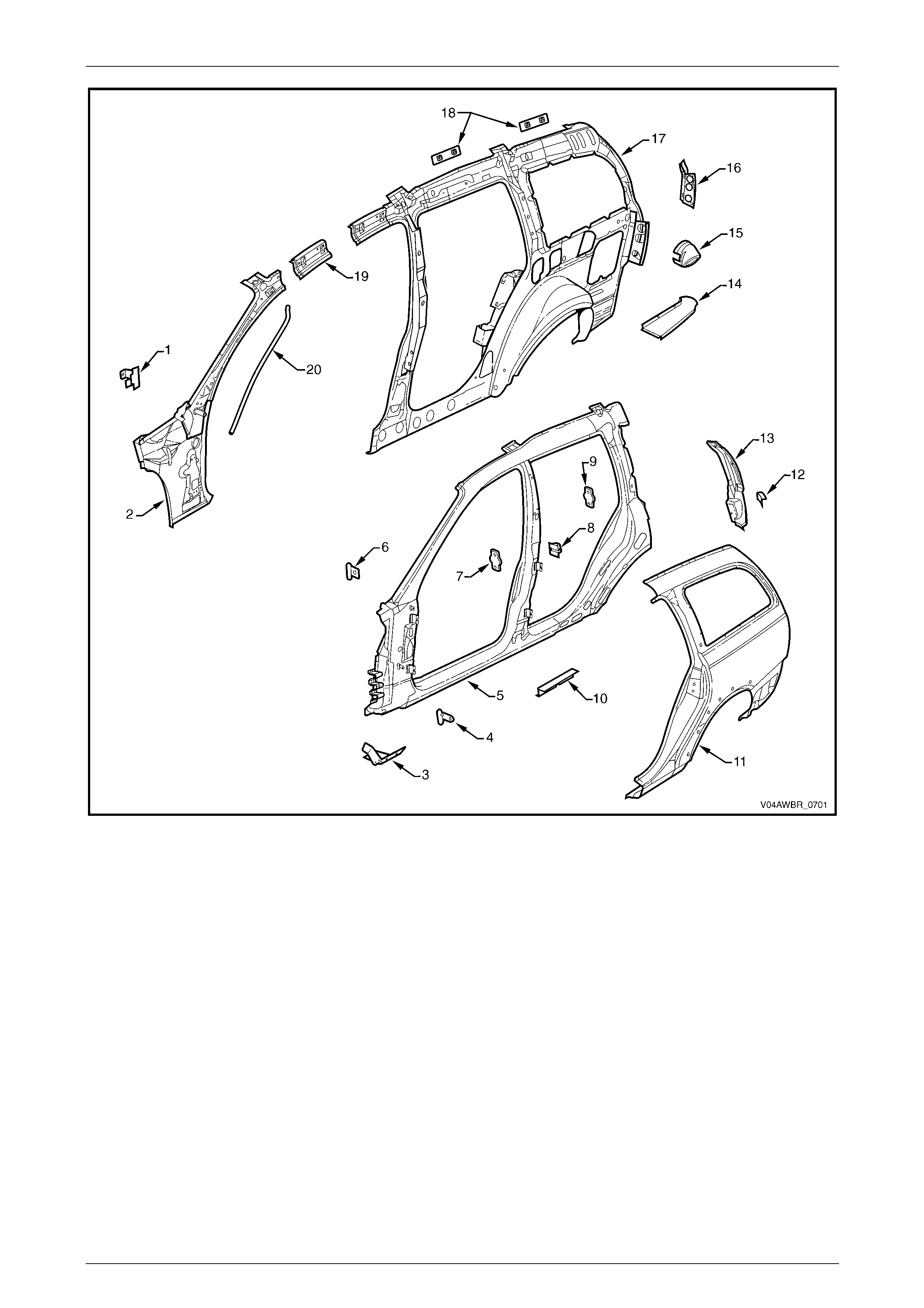
The components and assemblies shown in
Figure 7G – 2 are the serviceable parts that form the basis
of the repair procedures in this Section.
For a detailed view of the body components, refer to
Section 3G Body Construction – AWD Wagon.
NOTE
Always refer to an Authorised Retailer for spare
parts availability configurations.
Cavity foam may be used within the hinge,
centre and lock pillars. Care needs to be
taken when repairing the vehicle in these
areas, refer to Section 2 Precautions prior to
beginning any work for further information
regarding the use of cavity foam.
Figure 7G – 1
7G Body Side – AWD Wagon Page 7–3
Page 7–3
Figure 7G – 2
Legend
1 Hinge Pillar Trim Panel Bracket, Left-hand / Right-hand
2 Hinge Pillar Inner Panel Assembly, Left-hand / Right-hand
3 Fender Lower Rear Bracket, Left-hand / Right-hand
4 Fender Rear Bracket, Left-hand / Right-hand
5 Door Opening Frame Assembly, Left-hand / Right-hand
6 Fender Upper Rear Bracket, Left-hand / Right-hand
7 Front Door Striker Anchor Plate, Left-hand / Right-hand
8 Rear Door Check Link Bracket, Left-hand / Right-hand
9 Rear Door Striker Anchor Plate, Left-hand / Right-hand
10 Underbody Jacking Locator, Left-hand / Right-hand
11 Rear Quarter Panel, Left-hand / Right-hand
12 Rear Bumper Fascia Side bracket, Left-hand / Right-hand
13 Quarter Panel Extension, Left-hand / Right-hand
14 Quarter Outer Lower Rear Panel, Left-hand / Right-hand
15 Fuel Filler Pipe Housing, Right-hand
16 Quarrter Inner Lower Rear Extension, Left-hand / Right-hand
17 Quarter Panel Inner Assembly, Left-hand / Right-hand
18 Cargo Screen Reinforcement Assembly, Left-hand / Right-
hand
19 Quarter Panel Inner Extension, Left-hand / Right-hand
20 Sunroof Drain Tube
NOTE
• Door opening frame assembly (5) includes
parts 3, 4, 6, 7, 8, 9 and 10.
7G Body Side – AWD Wagon Page 7–4
Page 7–4
2 Service Operations
2.1 Rear Quarter Panel – Replace
To avoid the possibility of fire, take particular
care when cuttin g or w elding at the r ear of th e
vehicle. Remove the fuel tank and plug the
fuel lines.
Before performing any operations on the rear
quarter panel, remove the Stuffer Block from
within the rear quarter panel inner cavity.
Refer to Section 3G Body Construction –
AWD Wagon.
NOTE
• The rear quarter panel service part is not
supplied with the quarter panel extension or
for the right-hand side, the fuel filler pipe
housing. This Procedure details the
replacement of the r ear quarter p anel and fuel
filler pipe housing. If required, the quarter
panel extension can be replaced with the rear
quarter panel by including the procedures
from Section 7B Body Side – Wagon.
• Full replacement of the rear quarter panel
requires removal of the roof panel. This
procedure includes both full panel
replacement and partial replacement that
avoids removal of the roof panel.
7G Body Side – AWD Wagon Page 7–5
Page 7–5
Remove
1 Remove the adjacent bolt-on panels a nd components
as described in the appropriate Section of th e MY
2005 VZ Service Information.
2 Remove the rear window, refer to Section 1A6
Stationary Windows in the MY 2005 VZ Service
Information.
3 If full panel replacement is to be performed,
remove the roof joint moulding, refer to
Section 3G Body Construction – AWD Wagon, and
remove the roof panel, refer to Section 9B Roof.
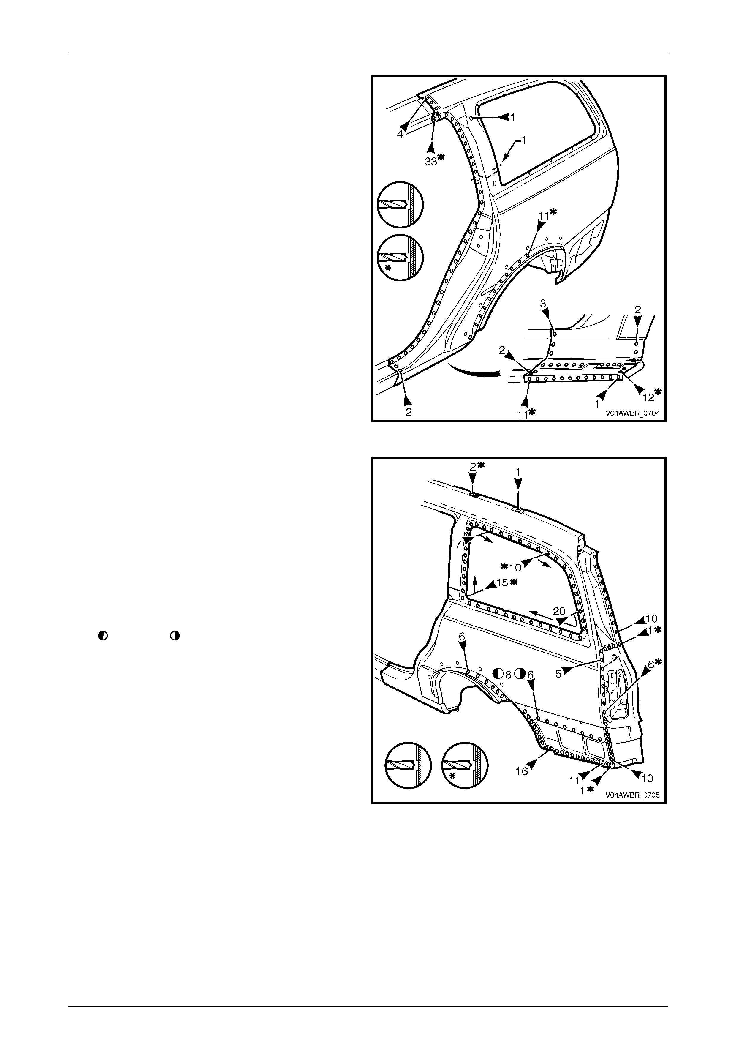
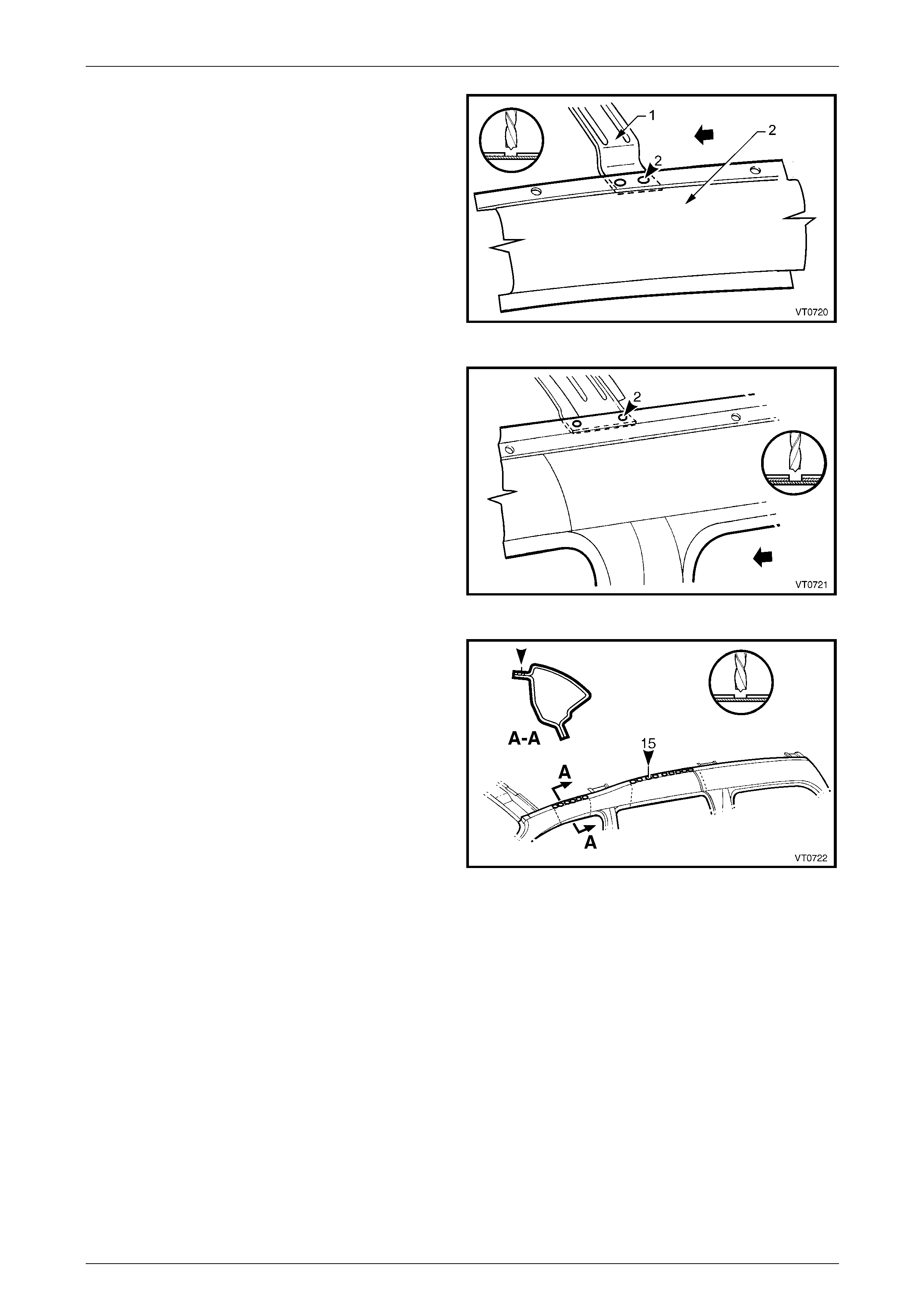
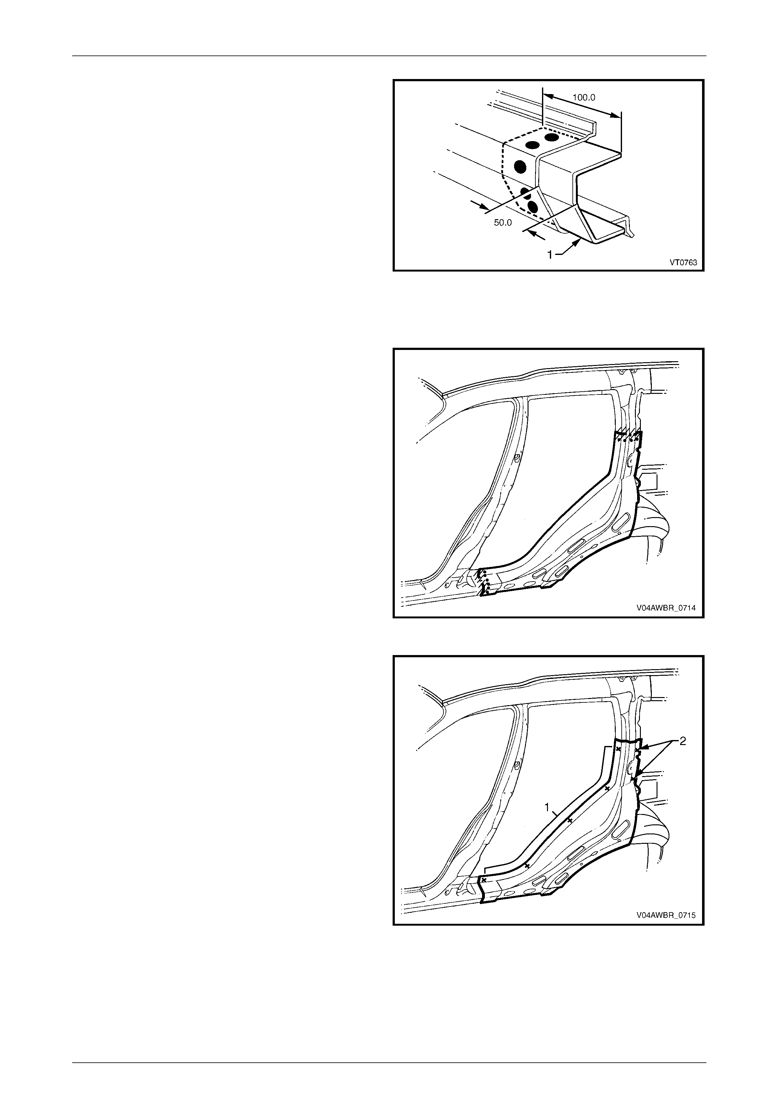
Figure 7G – 3
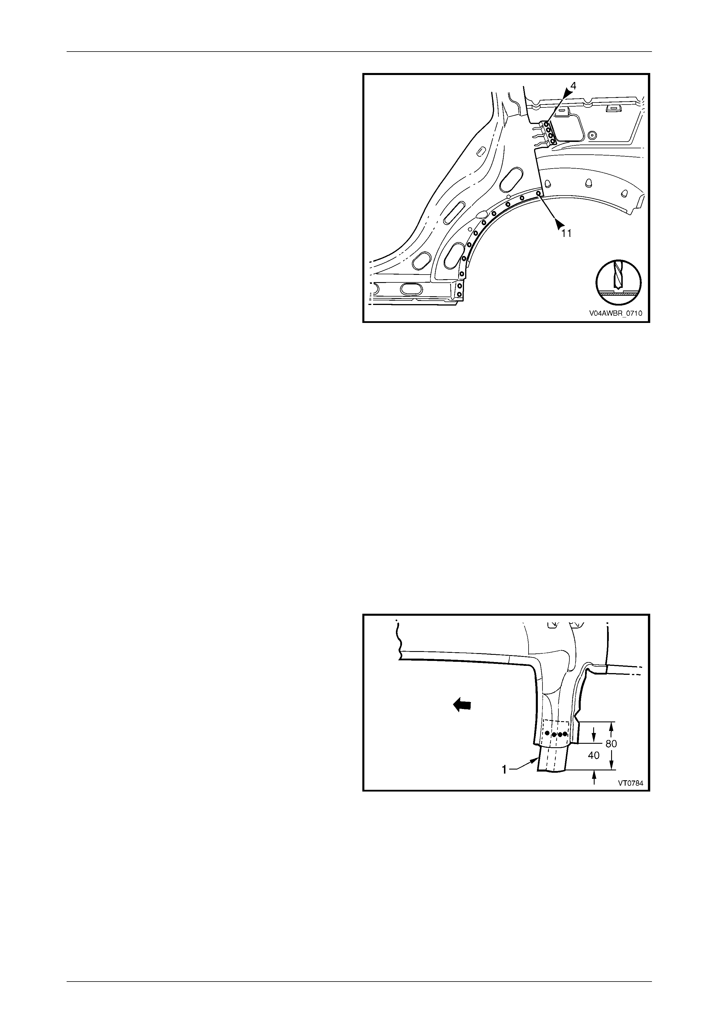
4 Partial replacement of the rear quarter panel is
possible by cutting the panel through the lock pillar,
50 mm above the datum hole (1) and the back pillar,
100 mm above the quarter panel extension (2). Ensure
that only the outer panel is cut.
Figure 7G – 4
7G Body Side – AWD Wagon Page 7–6
Page 7–6
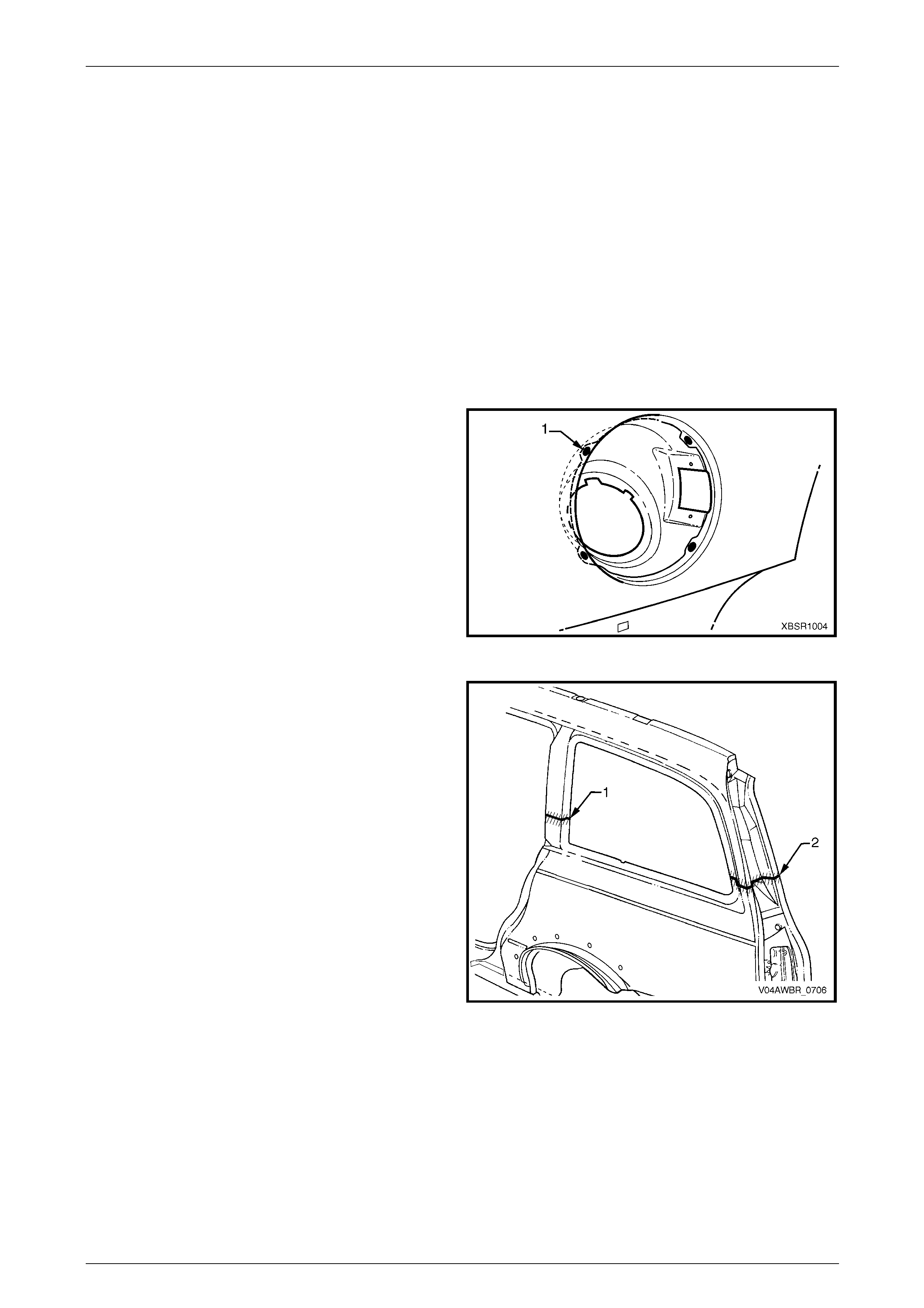
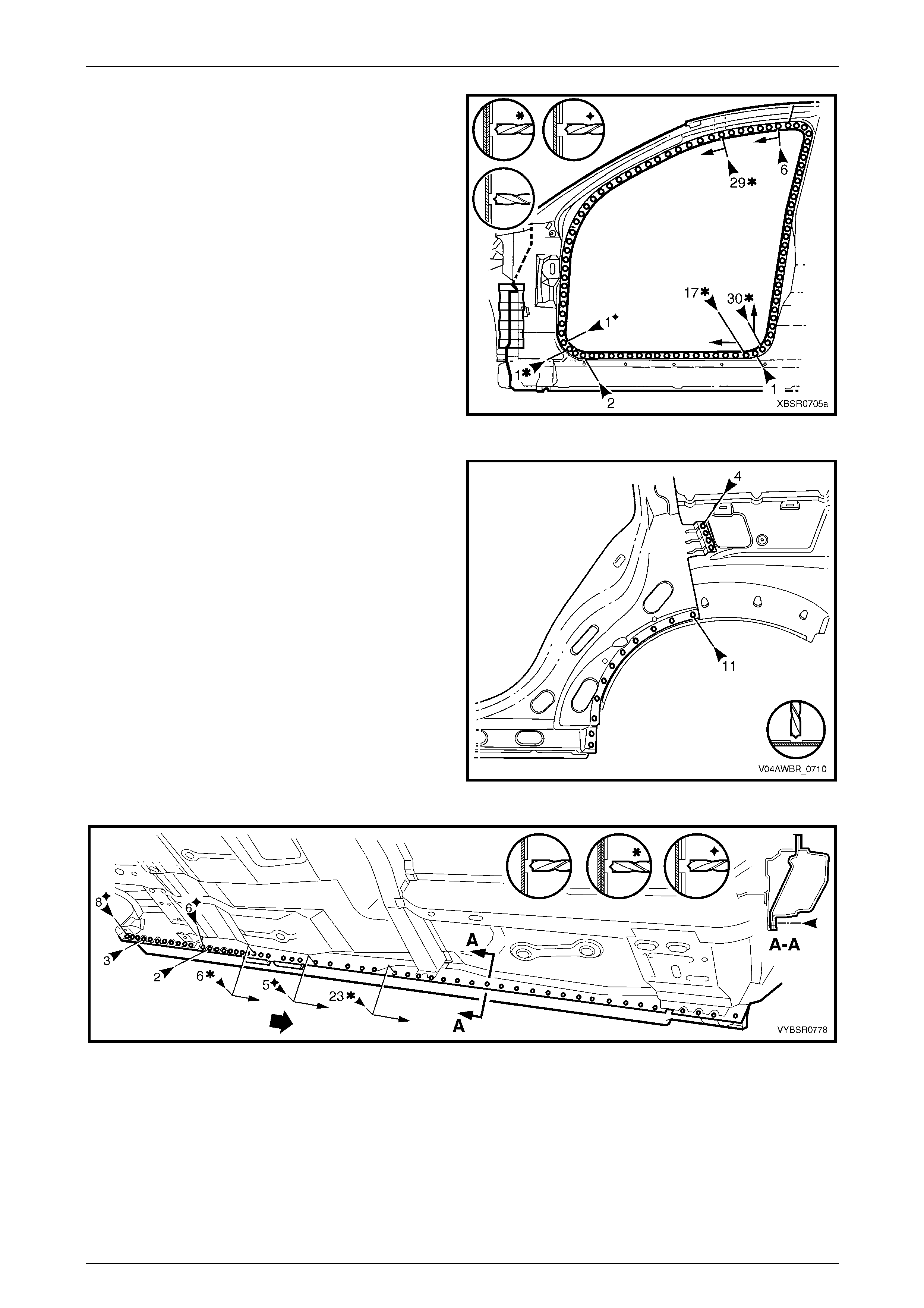
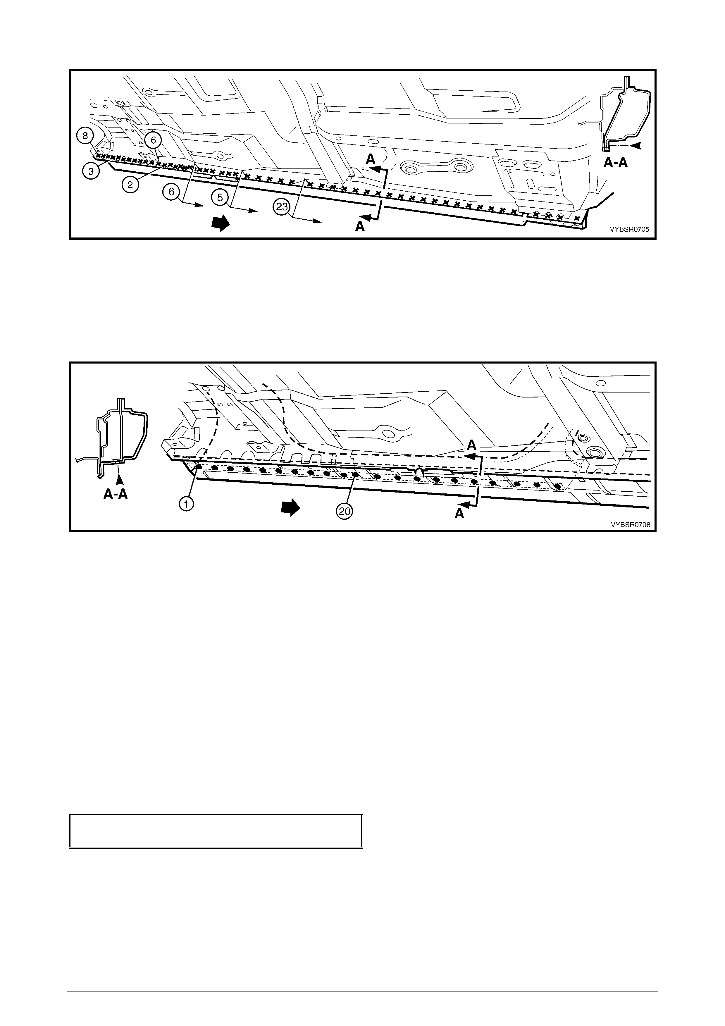
5 Spot cut the welds attaching the rear quarter panel
around the rear door opening and under the rocker
panel area. If a partial replacement is being
performed, remove the welds only to the cut point (1).
Figure 7G – 5
6 Spot cut the welds attaching the rear quarter panel to
the quarter panel inner assembly and quarter outer
lower rear panel and quarter panel extension. If a
partial replacement is being performed, remove the
welds only to the cut points.
NOTE
The quarter panel extension can be removed
with the rear quarter panel if required.
Refer to Section 7B Body Side – Wagon.
NOTE
= left-hand, = right-hand.
7 Remove the rear quarter panel from the vehicle, then
repair any damage to adjacent parts as required.
8 Check and rectify the alignme nt
of the body as required, refer to
Section 3G Body Construction – AWD Wagon.
Figure 7G – 6
7G Body Side – AWD Wagon Page 7–7
Page 7–7
Replace
NOTE
• Spot welding is the preferred method for
attaching of panels and should be used
whenever possible. Where the spot welding
equipment available will not access the
required weld position, a plug weld should be
performed.
• The same number and position of spot welds
(or plug welds) should be used when
replacing the panel, as was used during
manufacture, in order to maintain the original
structural strength of the vehicle.
1 If performing a partial panel replac ement, cut the new panel at the lock and back pillars to match the vehi cle.
2 For the right-hand side, if required spot or plug weld
(1) the fuel filler pipe housing to the rear quarter panel
in four places.
3 As required, mark the new panel with drilling locations
in preparation for plug welding. Drill holes as required.
4 Prepare all mating surfaces and treat with Weld
Through Primer (Item 1) as required, refer to
Section 3G Body Construction – AWD Wagon.
5 Apply Acrylic Spot Weld Sealer (Item 2), refer to
Section 3G Body Construction – AWD Wagon.
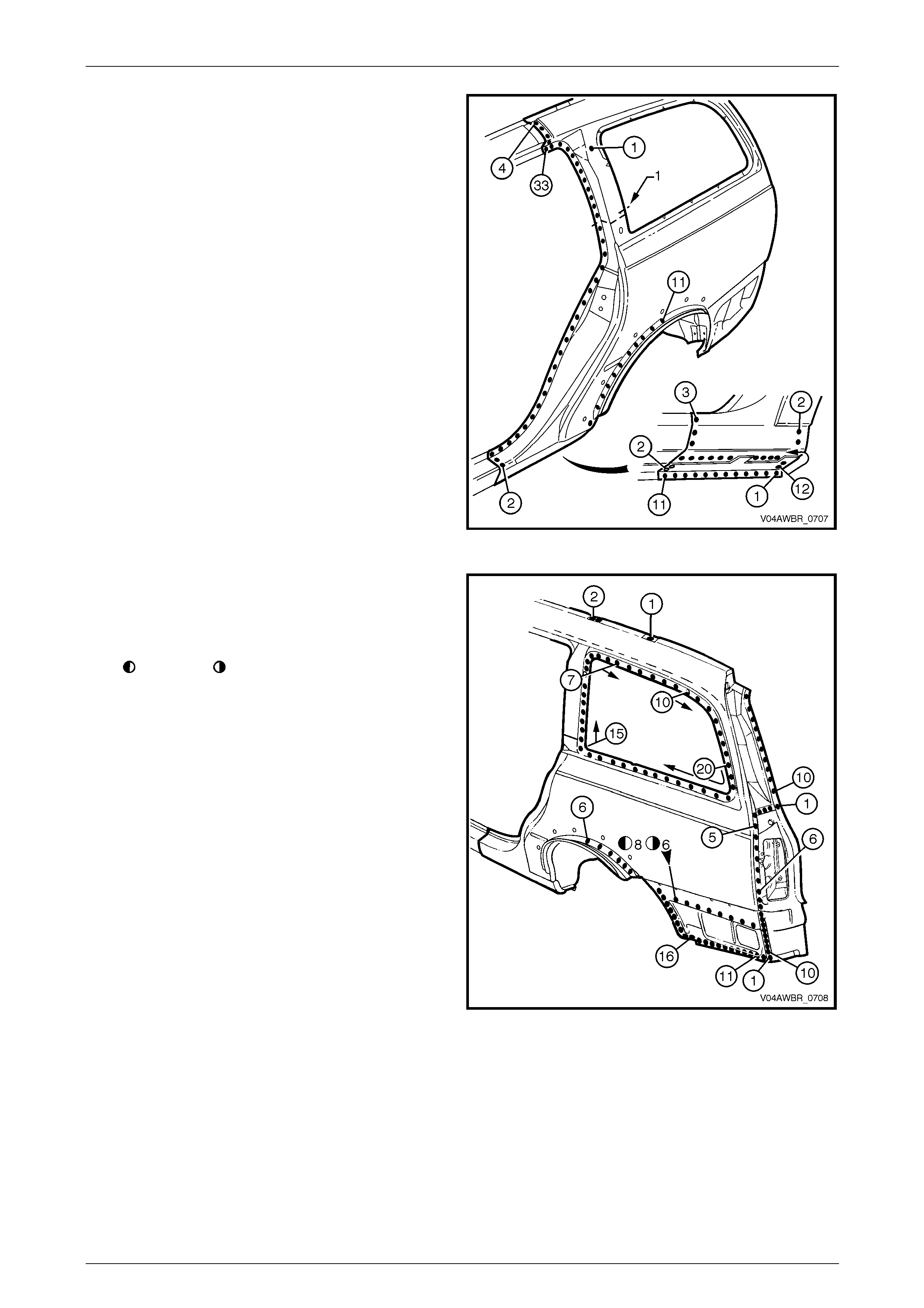
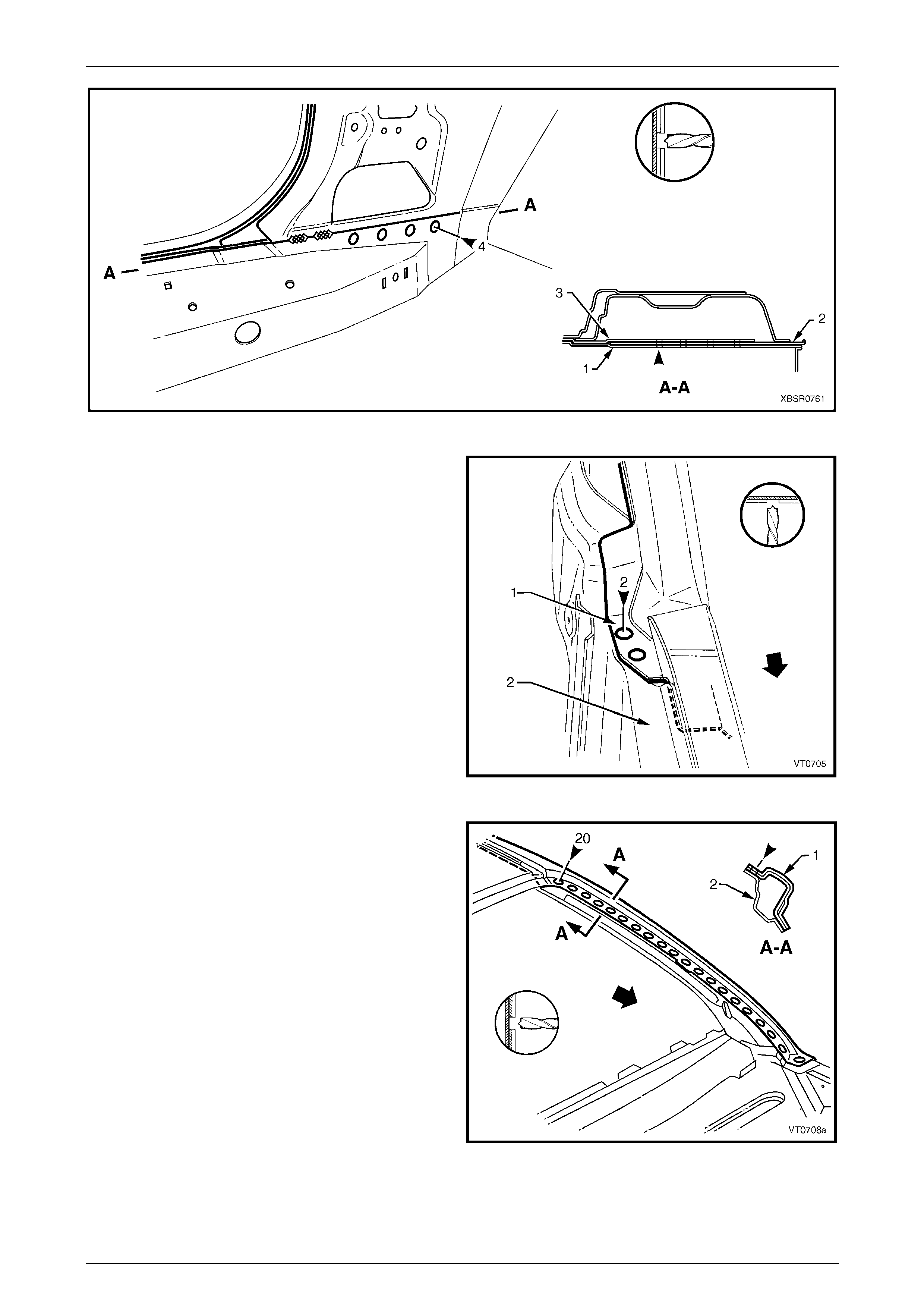
6 Clamp the new panel in position on the vehicle and
test fit the alignment with the rear door and liftgate. Figure 7G – 7
7 MIG butt weld across the panel joins if a partial pane l
replacement was performed.
Figure 7G – 8
7G Body Side – AWD Wagon Page 7–8
Page 7–8
8 Spot or plug weld the rear quarter panel ar ound the
door opening and rocker pane l.
Figure 7G – 9
9 Spot or plug weld the rear quarter panel to the quarter
panel inner assembly, quarter outer lower rear panel
and the quarter panel e xtens ion if still installed.
NOTE
= left-hand, = right-hand.
10 If removed, install the quarter pan el extension, refer to
Section 7B Body Side – Wagon.
11 If a partial replacement was performed, grind or sand
the lock and back pillar butt welds to achieve a smooth
finish ensuring that too much material is not removed.
12 Refinish and paint panels and other components as
required. Refer to Section 3 Body Construction .
13 Apply Joint Sealer (Item 3) as required. Refer to
Section 3G Body Construction – AWD Wagon.
14 Apply Cavity Wax (Item 8) as required to the inside of
any box sections or areas inaccessible to paint,
refer to Section 3 Body Construction.
15 Replace the Stuffer Block, refer to Section 3G Body
Construction – AWD Wagon.
16 Install the quarter window assembly, refer to
Section 1A6 Stationary Windows in the MY 2 005 VZ
Service Information
17 Install the remaining components as described in the
MY 2005 VZ Service Information.
Figure 7G – 10
7G Body Side – AWD Wagon Page 7–9
Page 7–9
2.2 Door Opening Frame Assembly –
Replace
NOTE
• This procedure requires the removal of the
roof panel. As an alternative, the door
opening frame assembly can be cut at the
upper pillar sections by following the
procedures in 3B Body Construction –
Wagon.
• Cavity Foam is used within the hinge, centre
and lock pillar cavities. Care is required when
repairing the vehicle in these areas, refer to
Section 2 Precautions prior to beginning any
work for further information.
Remove
1 Remove the adjacent bolt-on panels a nd components
as described in the appropriate Service Information.
2 Remove the windshield and the rear window
assemblies, refer to Section 1A6 Stationary Windows
in the MY 2005 VZ Service Information.
3 Remove the dash panel retaining bolt from the hinge
pillar.
4 Remove the roof panel, refer to Section 9 Roof .
5 Remove the rear quarter panel, refer to
2.1 Rear Quarter Panel – Replace.
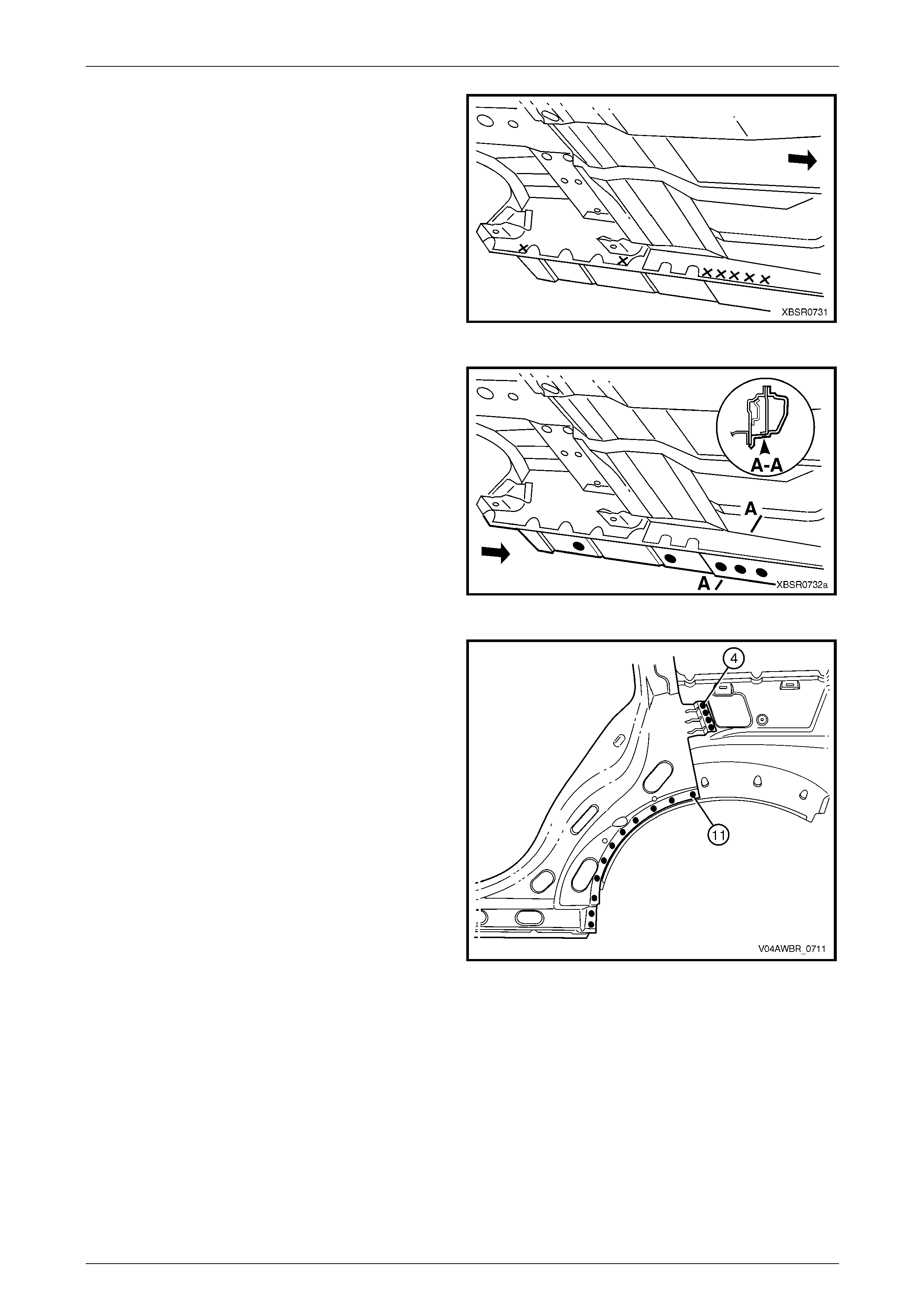
6 Remove the front wheelhouse pan el upper side rail,
refer to Section 4 Front End. Figure 7G – 11
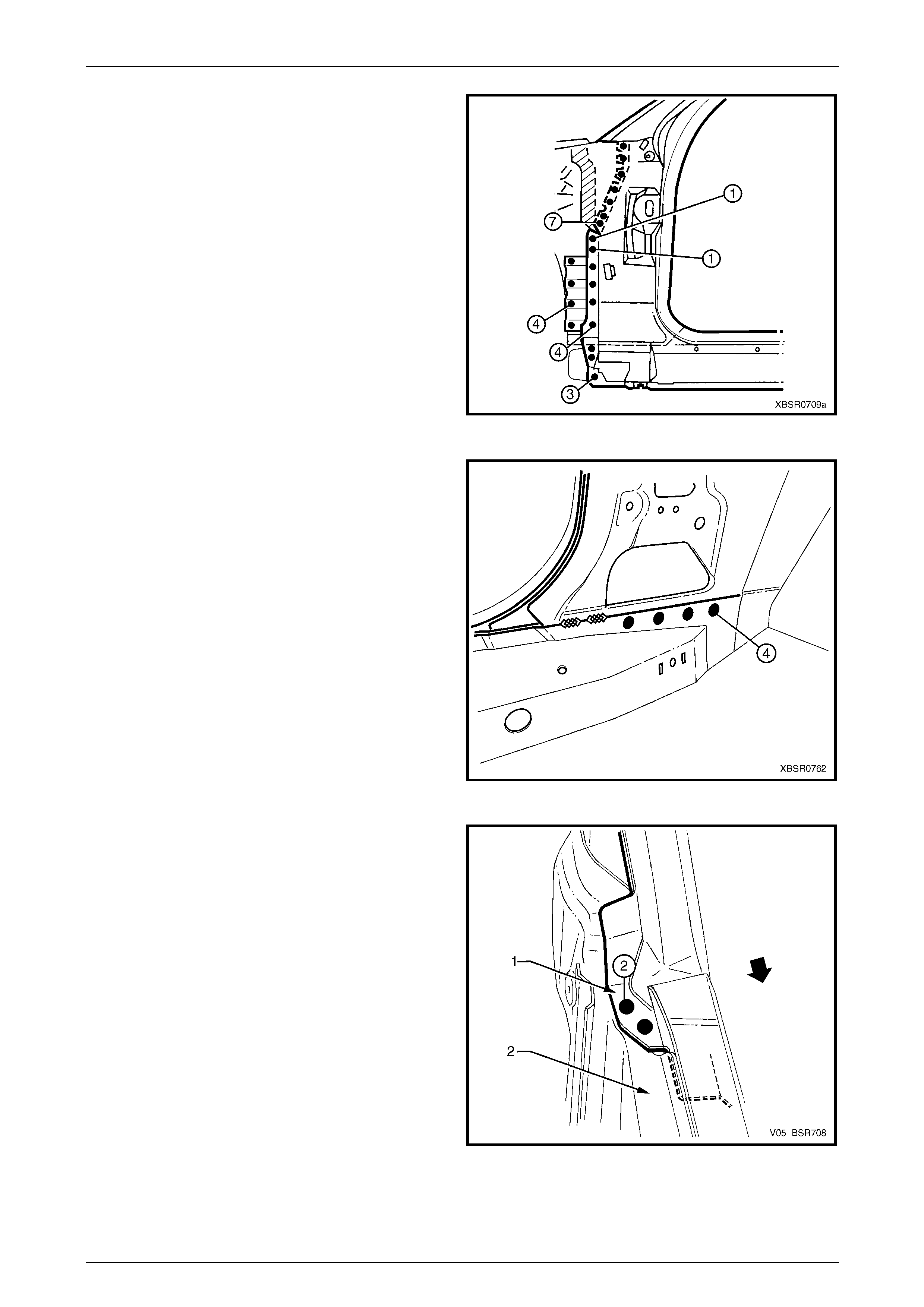
7 Spot cut the welds attaching the door openin g frame
assembly to the inner rocker panel and to the hin ge
pillar inner panel assembly.
NOTE
To spot cut the uppermost of these welds it may
be necessary t o cut and peel back the secti on of
hinge reinforcement pa nel covering the welds, to
gain the required access.
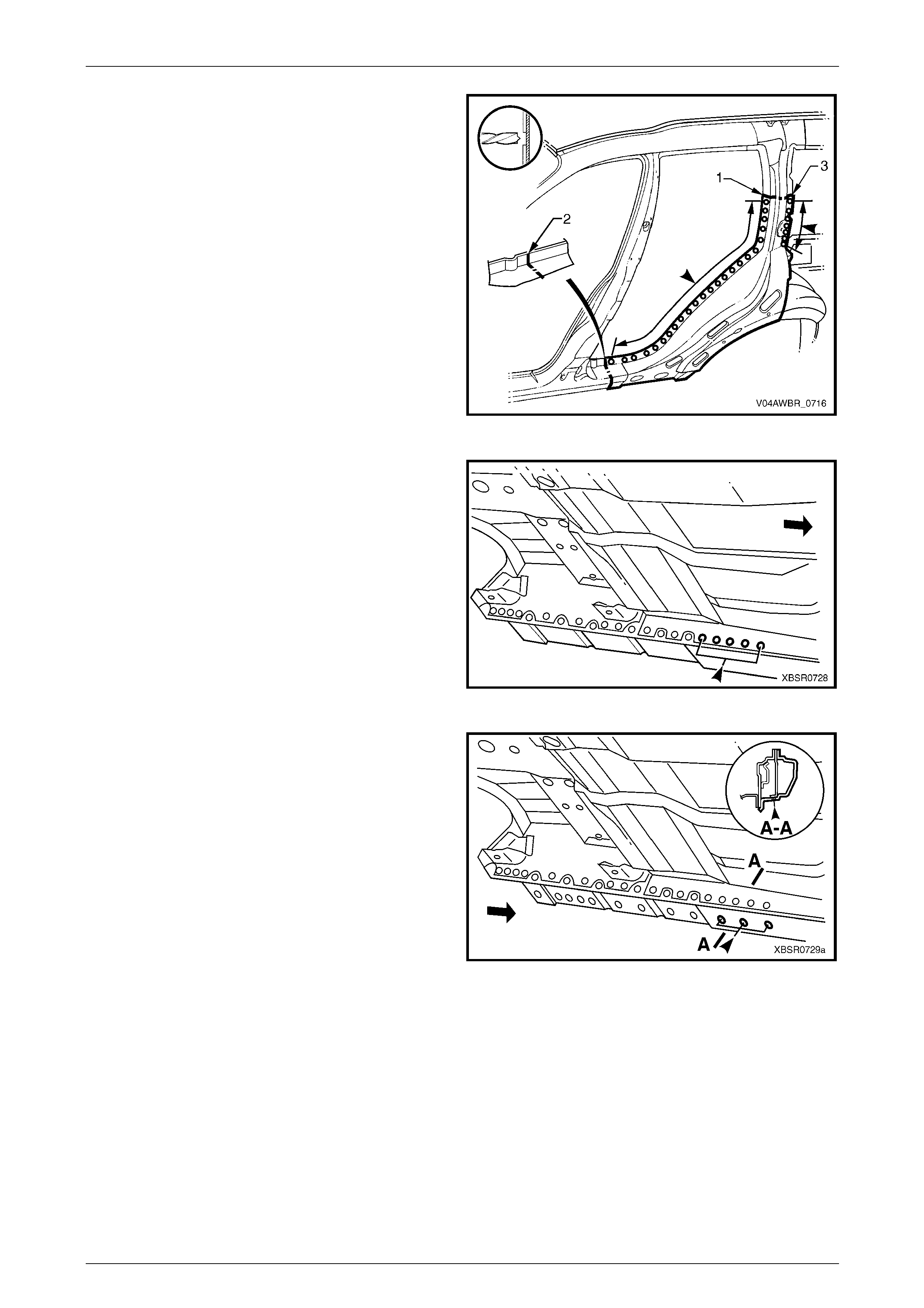
8 Spot cut the welds attaching the inner rocker panel (1)
and hinge pillar inner p an el assembly (2) to the rocker
panel reinforcement (3). Refer to Figure 7G – 13.
NOTE
It is not required to cut the MIG welds.
Figure 7G – 12
7G Body Side – AWD Wagon Page 7–10
Page 7–10
Figure 7G – 13
9 Spot cut the two welds at the base of the hinge pillar,
attaching the door opening frame assembly (1) to the
hinge pillar inner panel assembly (2).
Figure 7G – 14
10 Spot cut the welds on the windshield side flange,
attaching the door opening frame assembly (1) to the
hinge pillar inner panel assembly (2).
Figure 7G – 15
7G Body Side – AWD Wagon Page 7–11
Page 7–11
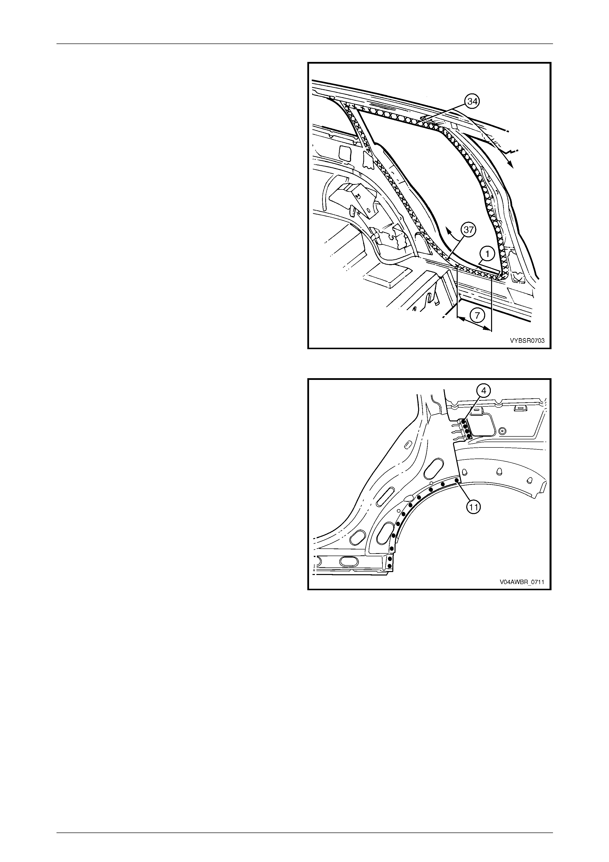
11 Spot cut the welds on the flange surrounding the front
door opening, attaching the door op ening frame
assembly to the hinge pillar inner pa nel assembly,
inner rocker panel and quarter panel inner assembly.
Figure 7G – 16
12 Spot cut the welds around the rear wheel arch, joining
the door opening frame assembly (1) to the quarter
panel inner assembly (2).
NOTE
Many may have been removed with the rear
quarter panel.
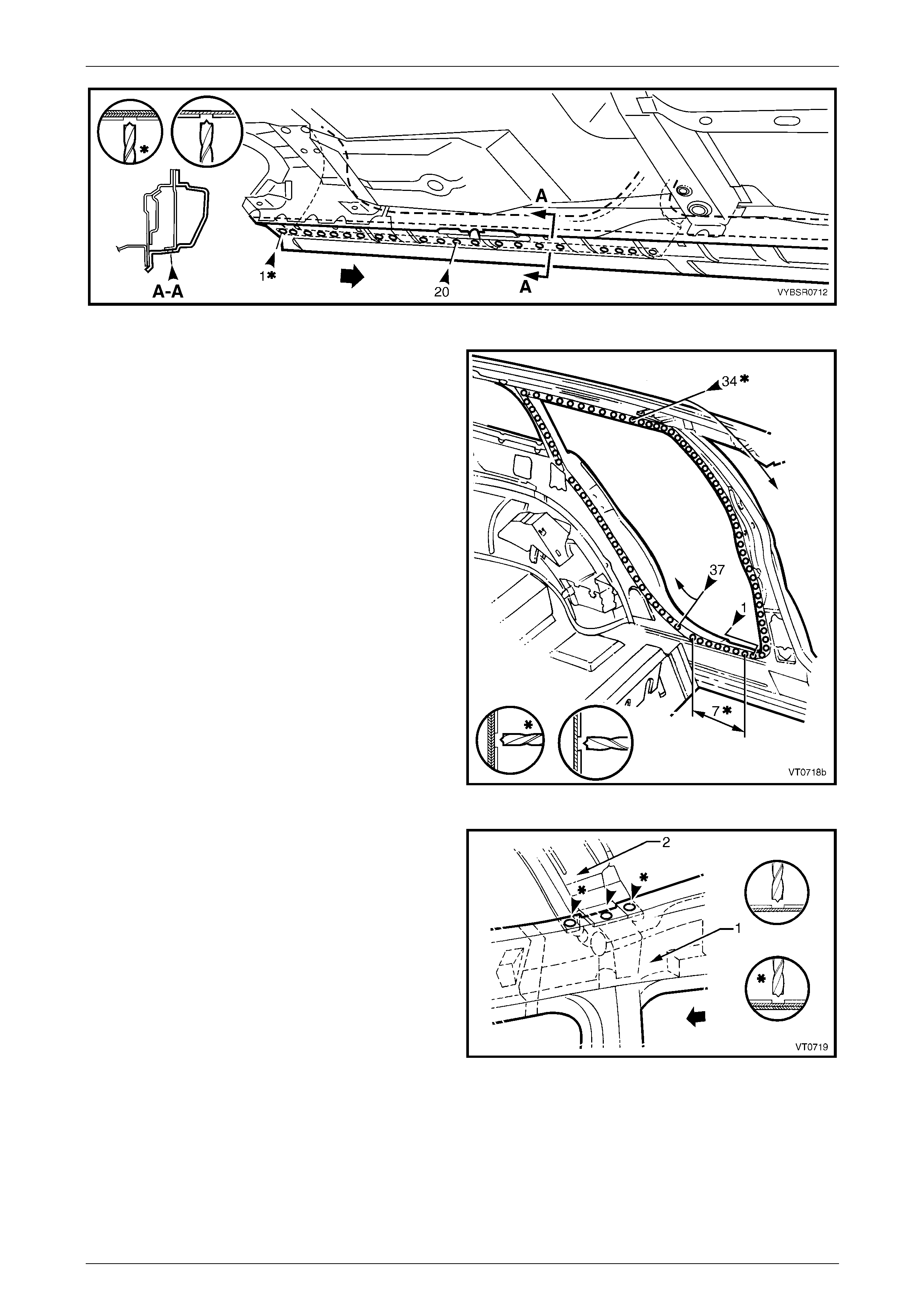
13 Spot cut along the vertical flange below the rocker
panel to separate the door opening frame assembly
from the inner rocker panel and the rear flo or pan el
outer extension. Refer to Figure 7G – 18.
Figure 7G – 17
Figure 7G – 18
14 Spot cut from below, up into the rocker panel, to separate the welds attaching the door opening frame assembly to
the quarter panel inner assembl y. Refer to Figure 7G – 19.
7G Body Side – AWD Wagon Page 7–12
Page 7–12
Figure 7G – 19
15 Spot cut the welds on the rear door opening flang e,
attaching the door opening fram e assembly to the
quarter panel inner assembly.
NOTE
Some welds may have been removed with the
quarter panel.
Figure 7G – 20
16 For vehicles without a sunroof, spot cut the two welds
attaching the roof bow panel (2) to the centre pillar
upper reinforcement, and the single weld attaching the
roof bow panel to the door opening frame assembly
(1).
Figure 7G – 21
7G Body Side – AWD Wagon Page 7–13
Page 7–13
17 For vehicles without a sunroof, spot cut the two welds
attaching roof bow panel No. 2 (1) to the door opening
frame assembly (2).
Figure 7G – 22
18 Spot cut the two welds attaching the roof bow panel
No. 3 to the door opening frame assembly and the
quarter panel inner assembly.
Figure 7G – 23
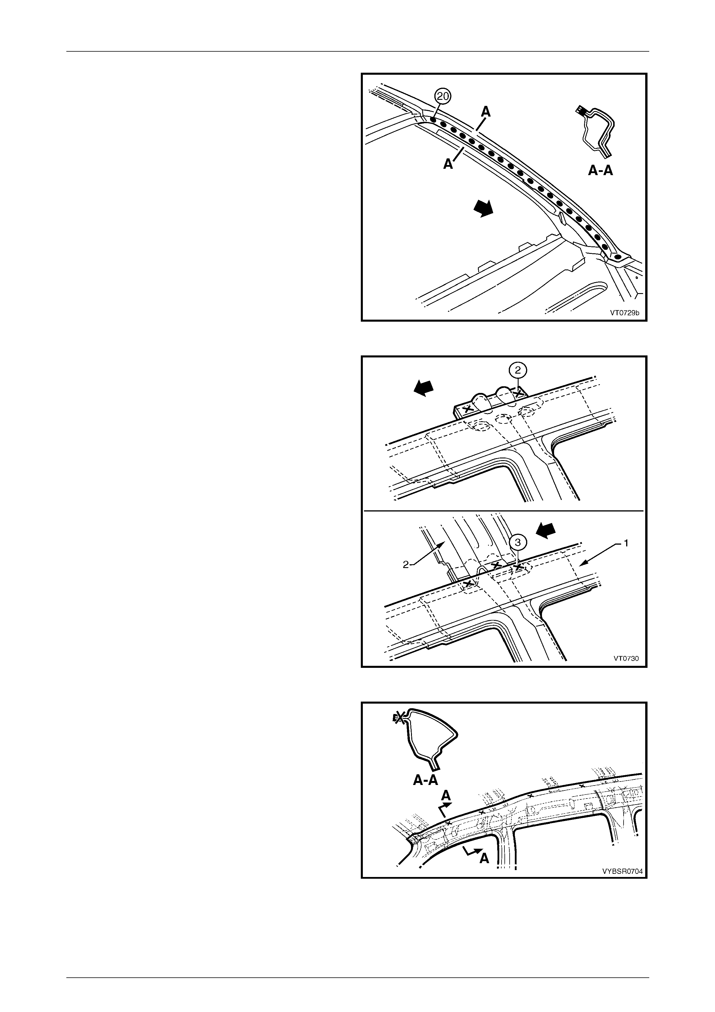
19 Spot cut the welds along the roof attachment flange.
NOTE
Many may have been removed with the roof
panel.
20 Remove the door opening fram e assembly and repair
any damage to adjacent parts as required.
21 Check and rectify the alignme nt
of the body as required, refer to
Section 3G Body Construction – AWD Wagon.
Figure 7G – 24
7G Body Side – AWD Wagon Page 7–14
Page 7–14
Replace
NOTE
• Spot welding is the preferred method for
attaching of panels and should be used
whenever possible. Where the spot welding
equipment available will not access the
required weld position, a plug weld should be
performed.
• The same number and position of spot welds
(or plug welds) should be used when
replacing the panel, as was used during
manufacture, in order to maintain the original
structural strength of the vehicle.
1 As required, mark the new panel with drilling locations in preparation for plug welding. Drill holes as required.
2 Prepare all mating surfaces and treat with Weld Through Primer (Item 1) as requir ed,
refer to Section 3G Body Construction – AWD Wagon.
3 Apply Acrylic Spot Weld Sealer (Item 2), refer to Section 3G Body Construction – AWD Wagon.
4 Securely clamp the door openin g frame assembly in
position on the vehicle body.
5 Begin attaching the door opening frame assembly by
spot welding around the front door opening flange.
Figure 7G – 25
7G Body Side – AWD Wagon Page 7–15
Page 7–15
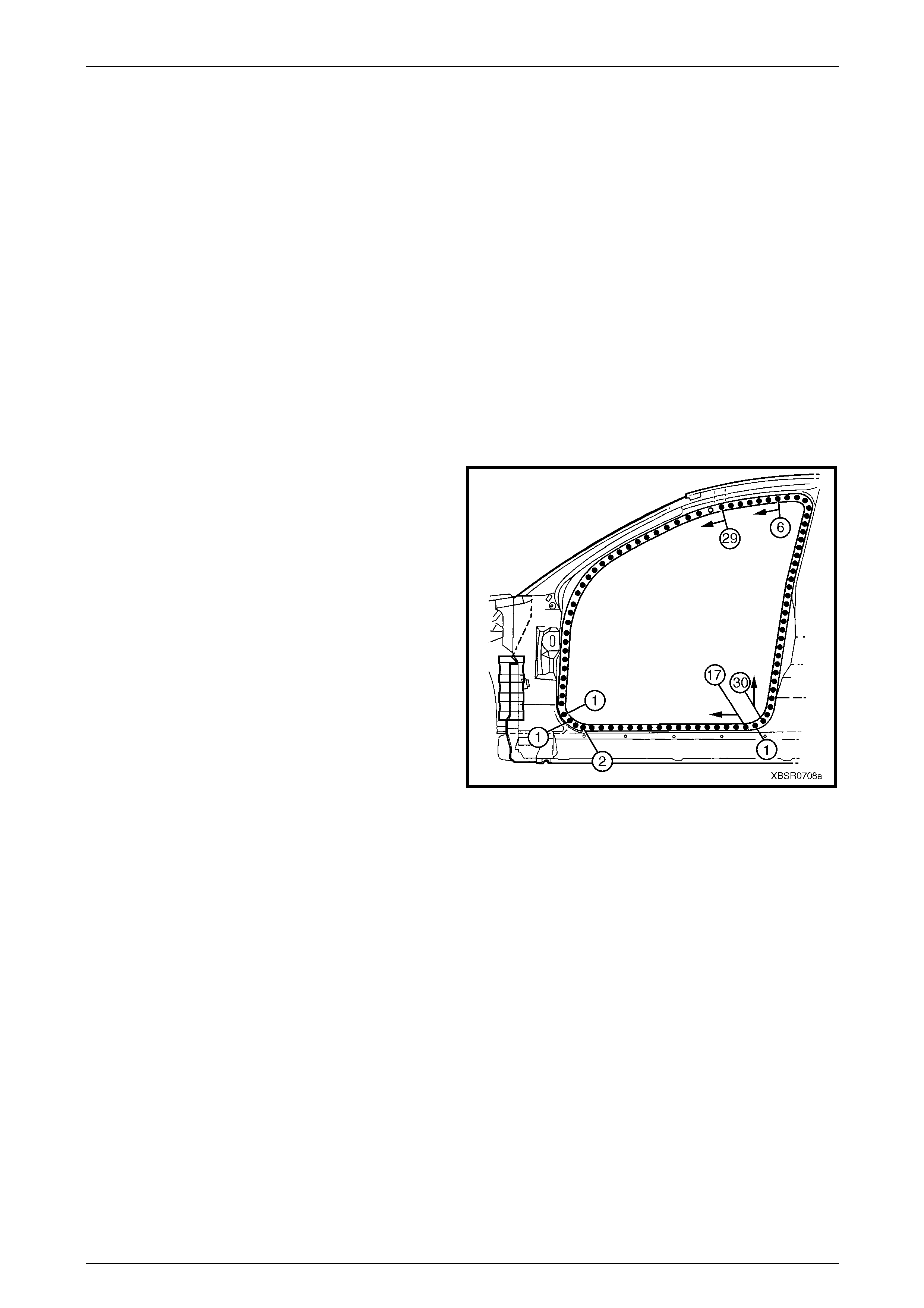
6 Spot weld around the flange of the rear door opening.
Figure 7G – 26
7 Spot or plug weld in two places arou nd the rear wheel
arch, attaching the door opening frame assembly to
the quarter panel inner assembl y.
NOTE
These welds will be completed when the rear
quarter panel is replaced.
Figure 7G – 27
7G Body Side – AWD Wagon Page 7–16
Page 7–16
8 Spot or plug weld the door opening frame assembly to
the inner rocker panel and to the hinge pillar inner
panel assembly. If the sheet metal was modified to
allow access to these welds, it should be repaired to
its original configuration.
Figure 7G – 28
9 Plug weld the inner rocker pa nel and hinge pillar inner
panel assembly to the rocker panel reinforcement.
Figure 7G – 29
10 Spot or plug weld the door opening frame assembly
(1) to the hinge pillar inner panel assembly (2) at the
base of the hinge pillar
Figure 7G – 30
7G Body Side – AWD Wagon Page 7–17
Page 7–17
11 Spot or plug weld along the windshield flange,
attaching the door opening frame assembly (1) to the
hinge pillar inner panel assembly (2).
Figure 7G – 31
12 For vehicles without a sunroof, spot or plug weld the
door opening frame assembly (1) to the quarter inner
panel assembly, then spot or plug weld the roof bow
panel (2) to the door opening frame assembly as
shown.
Figure 7G – 32
13 Spot or plug weld the door opening frame assembly to
the quarter inner panel assembly along the roof panel
flange. Complete this flange when installing the roof
panel.
14 Spot or plug weld the door opening frame al ong the
vertical flange belo w the rocker panel, refer to
Figure 7G – 34.
Figure 7G – 33
7G Body Side – AWD Wagon Page 7–18
Page 7–18
Figure 7G – 34
15 Plug weld up through the rocker panel to attach the door opening frame assembly to the quarter p anel inner
assembly. Refer to Figure 7G – 35.
NOTE
Leave some welds to until the rear quarter panel
is installed.
Figure 7G – 35
16 Replace front wheelhous e panel upper side rail, refer to Section 4 Front End.
17 Replace the rear quarter panel, refer to 2.1 Rear Quarter Pane l – Replace.
18 Replace the roof panel, refer to Section 9D R oof.
NOTE
Refinish and prime any bare metal as required
prior to replacing these panel s.
19 Install the door hinge flaps, refer to Section 8 Doors, Liftgate and Endgate.
20 Refinish and paint panels and other components as required. Refer to Section 3 Body Construction.
21 Apply Joint Sealer (Item 3) as required. Refer to Section 3G Body Construction – AWD Wagon.
22 Apply Cavity Wax (Item 8) as required to the inside of any box secti ons or areas inaccessible to paint,
refer to Section 3G Body Construction – AWD Wagon.
23 Apply Spray-on Dea dener (Item 7) where applicab le, refer to Section 3G Body Construction – AWD Wagon.
24 Install the dash panel retaining bolt throu gh the hinge pil lar and tighten to the specified torque.
Dash panel retaining b olt
torque specification.................................35.0 – 45.0 Nm
25 Replace the windshield and quarter window assembl y, refer to Section 1A 6 Stationary Windows in the MY 2005 VZ
Service Information.
26 Insert Cavity Foam into the centre pillar as required, refer to Section 2 Precautions.
27 Install the remaining components as described in the appropriate Section of the MY 2005 VZ Service Information.

7G Body Side – AWD Wagon Page 7–19
Page 7–19
2.3 Door Opening Frame Assembly – Partial
Replace, Lock Pillar
Remove
1 Remove the adjacent bolt-on panels a nd components
as described in the appropriate Section of th e MY
2005 VZ Service Information.
2 Install the vehicle on a suitab le fixture. As a minimum,
support the appropriate structural sections of the
vehicle on safety stands.
3 Remove the rear window assembly, refer to
Section 1A6 Stationary Windows in the MY 2 005 VZ
Service Information.
4 Remove the rear quarter panel, refer to
2.1 Rear Quarter Panel – Replace.
Figure 7G – 36
5 Select a cut point (1) on the upper region of the lock
pillar within the area specified.
6 Carefully cut through the outer panel, leaving the
quarter panel inner assembly (2) intact.
NOTE
There is no reinforcement panel in this area of
the vehicle.
Figure 7G – 37
7 Select a cutting position on the rocker panel section of
the door opening frame assembly, rear of the dimple in
the flange (1). If possible, make the cut in the area that
will be covered by the rear quarter panel. Cut through
the outer panel (2), leaving the quarter pan el inner
assembly (3) intact.
Figure 7G – 38
7G Body Side – AWD Wagon Page 7–20
Page 7–20
8 Spot cut the welds on the flange around the rear door
opening attaching the section of the door opening
frame assembly to the quarter panel in ner assembly.
Begin from the cut through the top of the pilla r (1) and
continue to the cut through the rocker panel section (2)
as required.
NOTE
Some of the welds shown may have been
removed with the rear quarter panel.
9 Spot cut the welds down the flange of the rear side
glass opening (3), beginning a t the point of the cut
through the lock pillar.
Figure 7G – 39
10 Spot cut the welds on the flange below the rocker
panel as required, attaching the do or opening frame
assembly to the inner rocker panel.
NOTE
Spots rear of those shown may have been
removed with the rear quarter panel, if not
remove any remaining.
Figure 7G – 40
11 Spot cut the welds below the rocker panel as required,
attaching the door opening fram e assembly to the
quarter panel inner assembly.
NOTE
Spots rear of those shown may have been
removed with the rear quarter panel, if not
remove any remaining.
Figure 7G – 41
7G Body Side – AWD Wagon Page 7–21
Page 7–21
12 Spot cut any welds remaining around the wheel house
as required (most would have been removed with the
rear quarter panel), attaching the door o pe ning frame
assembly (1) to the quarter panel inner assembly (2).
13 Remove the replacement sect ion from the vehicle,
then repair any damage to adjacent parts as required.
14 Check and rectify the alignme nt
of the body as required, refer to
Section 3G Body Construction – AWD Wagon.
Figure 7G – 42
Replace
NOTE
• Spot welding is the preferred method for
attaching of panels and should be used
whenever possible. Where the spot welding
equipment available will not access the
required weld position, a plug weld should be
performed.
• The same number and position of spot welds
(or plug welds) should be used when
replacing the panel, as was used during
manufacture, in order to maintain the original
structural strength of the vehicle.
1 Cut a replacement section from a new door opening frame assembly, accurately measuring the position of cuts to
match the removed section.
2 Manufacture a reinforcement ( 1), or cut a pie ce from
excess pillar section, appro ximately 80 mm in length to
match the inside face only of the cut lock pi llar section.
3 Prepare the mating surfaces and treat with Weld
Through Primer (Item 1) as required, refer to
Section 3G Body Construction – AWD Wagon.
4 Clamp the reinforcement firmly behind the cut face of
the lock pillar section of the door openi ng frame
assembly on the vehicle and spot or plug weld in
place.
Figure 7G – 43
7G Body Side – AWD Wagon Page 7–22
Page 7–22
5 Using the same technique, manufactur e or cut a
section of reinforcement panel (1), approx. 100 mm
long, to fit inside the existing rocker panel at the point
of the cut.
6 Prepare the mating surfaces and treat with Weld
Through Primer (Item 1) as required, refer to
Section 3G Body Construction – AWD Wagon.
7 Clamp the manufactured reinforcement pan el inside
the rocker panel section of the door opening frame
assembly on the vehicle and p lug weld in position.
Position welds at a maximum spacing of 35 mm.
8 Mark the replacement section with drillin g locations in
preparation for plug welding. Drill holes as required.
9 Prepare all mating surfaces and treat with Weld
Through Primer (Item 1) as required, refer to
Section 3G Body Construction – AWD Wagon.
Figure 7G – 44
10 Clamp the new lock pillar section in place on the
vehicle and check the door opening dimensions,
refer to Section 3G Body Construction – AWD Wagon.
11 Plug weld the replacement panel to the ma nufactured
reinforcement sections in the rocker panel area and at
the top of the pillar.
12 MIG butt weld the joins in both these areas.
Figure 7G – 45
13 Spot weld several places alon g the flange around the
rear door opening (1) to retain new section in position.
NOTE
Fully spot weld this flange when the
rear quarter panel is installed, welding
through all three panels, refer to
2.1 Rear Quarter Panel – Replace.
14 The flange of the rear side glass ope ning (2) may be
spot welded in one or t wo places to hold i n position.
NOTE
Final weld this flange when the
rear quarter panel is installed, refer to
2.1 Rear Quarter Panel – Replace.
Figure 7G – 46
7G Body Side – AWD Wagon Page 7–23
Page 7–23
15 Spot weld the flange below the rocker panel as
required, attaching the replac ement section to the
inner rocker panel.
NOTE
Where the rear quarter panel locates,
place two welds to secure the replacement
section. Final weld this flange when the
rear quarter panel is installed, refer to
2.1 Rear Quarter Panel – Replace.
Figure 7G – 47
16 Plug weld below the rocker panel as required,
attaching the replacement section to the quarter panel
inner assembly.
NOTE
Where the rear quarter panel locates,
place two welds to secure the replacement
section. Final weld this flange when the
rear quarter panel is installed, refer to
2.1 Rear Quarter Panel – Replace.
Figure 7G – 48
17 Spot weld several places around the wheelhouse to
retain new section in position.
NOTE
Fully spot weld this flange when the
rear quarter panel is installed, refer to
2.1 Rear Quarter Panel – Replace.
18 Clean up the welds made where the rear quarter panel
is located and prime all bare metal.
19 Replace rear quarter panel, refer to
2.1 Rear Quarter Panel – Replace.
20 Refinish and paint panels and other components as
required. Refer to Section 3 Body Construction .
21 Apply Joint Sealer (Item 3) as required. Refer to
Section 3G Body Construction – AWD Wagon.
22 Apply Cavity Wax (Item 8) as required to the inside of
any box sections or areas inaccessible to paint,
refer to Section 3G Body Construction – AWD Wagon.
23 Install the quarter window assembly, refer to
Section 1A6 Stationary Windows in the MY 2 005 VZ
Service Information.
24 Install the remaining components as described in the
appropriate Section of the MY 2005 VZ Servic e
Information.
Figure 7G – 49