
8 Doors, Liftgate and Endgate Page 8-1
Page 8-1
Section 8
Doors, Liftgate and Endgate
ATTENTION
Before performing any service operation or other procedure described in this Section, refer to Section 2
Precautions in this Supplement and Section 00 Warnings, Cautions and Notes in the MY 2005 VZ Service
Information for correct workshop practices with regard to safety and/or property damage.
The structure of the body shell has been
developed using complex design and
development techniques. In addition to
meeting all required standards, the vehicle
body is also a critical part of the overall safety
systems. It is therefore imperative the repair
procedures described here are adhered to
during all vehicle body repairs.
1 General Description ...............................................................................................................................3
1.1 Doors, Liftgate and Endgate Components.......................................................................................................... 3
Front Door, excluding Coupe................................................................................................................................ 3
Front Door, Coupe................................................................................................................................................. 4
Rear Door, Sedan................................................................................................................................................... 4
Rear Door, Wagon and Crew Cab......................................................................................................................... 5
Liftgate, Wagon...................................................................................................................................................... 5
Liftgate, AWD Wagon ............................................................................................................................................ 6
Endgate, Utility and Crew Cab.............................................................................................................................. 6
2 Service Operations.................................................................................................................................7
2.1 Front Door Assembly – Replace........................................................................................................................... 7
Remove................................................................................................................................................................... 7
Reinstall.................................................................................................................................................................. 8
Adjust...................................................................................................................................................................... 9
2.2 Rear Door Assembly – Replace.......................................................................................................................... 10
Remove................................................................................................................................................................. 10
Reinstall................................................................................................................................................................ 11
Adjust.................................................................................................................................................................... 11
2.3 Door Hinge (Body Side) – Replace..................................................................................................................... 12
Remove................................................................................................................................................................. 12
Reinstall................................................................................................................................................................ 12
2.4 Front Door Outer Panel – Replace...................................................................................................................... 14
Remove................................................................................................................................................................. 14
Replace................................................................................................................................................................. 15
2.5 Rear Door Outer Panel – Replace....................................................................................................................... 17
Remove................................................................................................................................................................. 17
Replace................................................................................................................................................................. 18

8 Doors, Liftgate and Endgate Page 8-2
Page 8-2
2.6 Liftgate Assembly – Replace .............................................................................................................................. 20
Remove................................................................................................................................................................. 20
Reinstall................................................................................................................................................................ 21
Adjust.................................................................................................................................................................... 22
2.7 Liftgate Outer Panel, except AWD Wagon – Replace ....................................................................................... 23
Remove................................................................................................................................................................. 23
Replace................................................................................................................................................................. 24
2.8 Liftgate Outer Panel, AWD Wagon – Replace.................................................................................................... 26
Remove................................................................................................................................................................. 26
Replace................................................................................................................................................................. 28
2.9 Endgate Assembly – Replace............................................................................................................................. 29
Remove................................................................................................................................................................. 29
Reinstall................................................................................................................................................................ 29
Adjust.................................................................................................................................................................... 30
2.10 Endgate Outer Panel – Replace.......................................................................................................................... 31
Remove................................................................................................................................................................. 31
Replace................................................................................................................................................................. 32
3 Torque Wrench Specifications............................................................................................................33
4 Special Tools ........................................................................................................................................34
8 Doors, Liftgate and Endgate Page 8-3
Page 8-3
1 General Description
This Section describes the repair and re placement procedures for the door s, Wagon and AWD Wagon liftgate and Utility
and Crew Cab endgate.
The procedures are limited to the replacement the door, liftgate or endgate assembl y or the outer pan el, which is
attached to the inner panel assembly by way of a folded hem flange and structural ad hesive. Removal of bolt-on trim and
hardware components is not covere d in this Supplement. Reference must be made to the appropriate Sections in the MY
2005 VZ Service Information.
The door assemblies are supplie d with the door hinge flaps that are MIG welded to the door opening frame assembly.
The door impact beams must not be heated,
welded or straightened in any way, due to
their critical role in driver/passenger safety.
Damage to the impact beams will necessitate
the replacement of the entire door assembly.
NOTE
It is imperative that the correct body adhesives,
sealers, deadeners and cavity waxes are used
when repairing the body structure. Refer to
Section 3 Body Construction for details of the
correct materials and their commercially available
equivalents.
1.1 Doors, Liftgate and Endgate
Components
The components and assemblies shown in Figure 8 – 1 – Figure 8 – 4 are the serviceable parts that form the basis of the
repair procedures in this Section. For a detailed view of the body components, refer to Section 3 Body Construction.
NOTE
Always refer to an Authorised Retailer for spare
parts availability configurations.
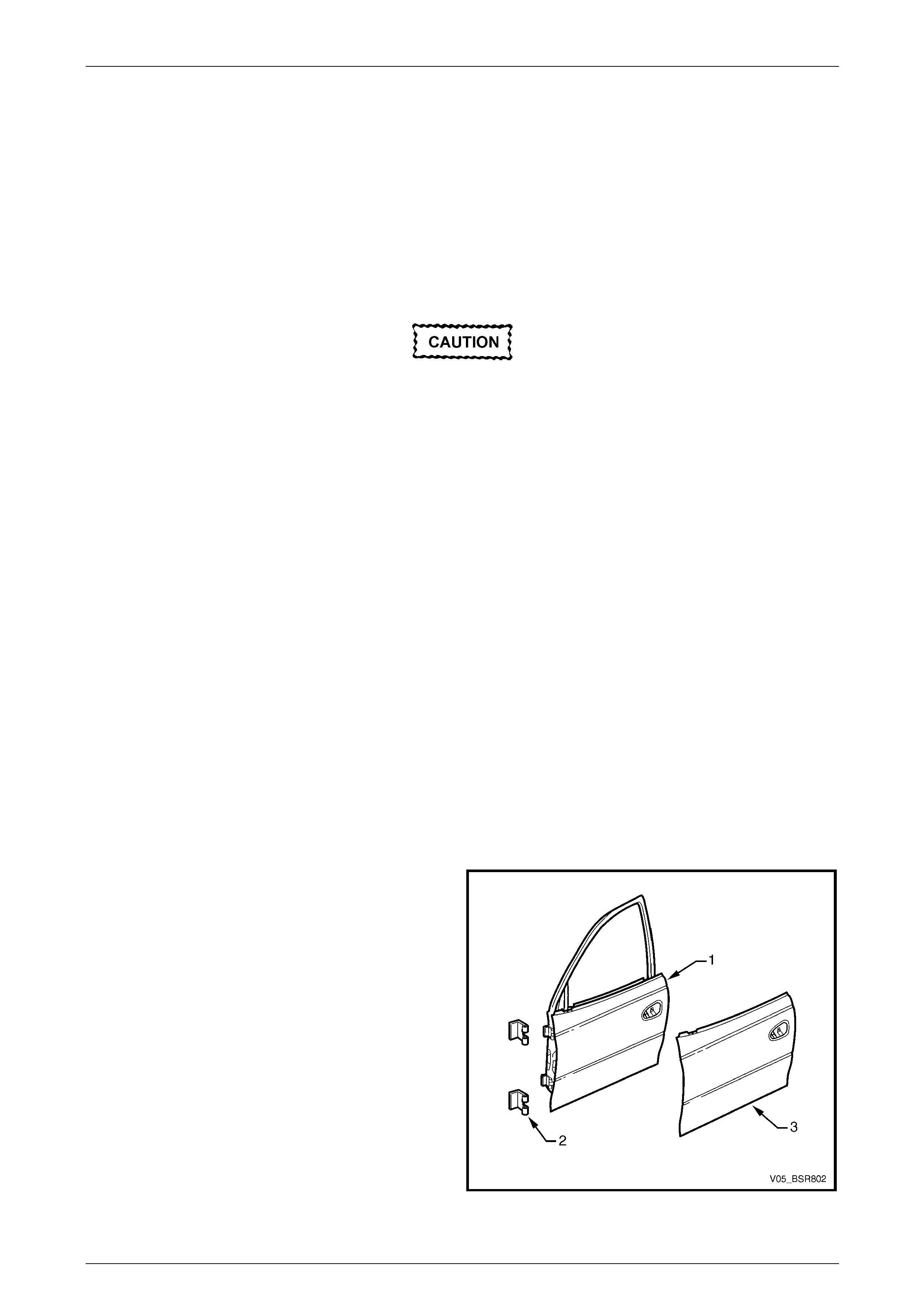
Front Door, excluding Coupe
Legend
1 Front Door Assembly
2 Front Door Hinge (Body Side)
3 Front Door Outer Panel
Figure 8 – 1
8 Doors, Liftgate and Endgate Page 8-4
Page 8-4
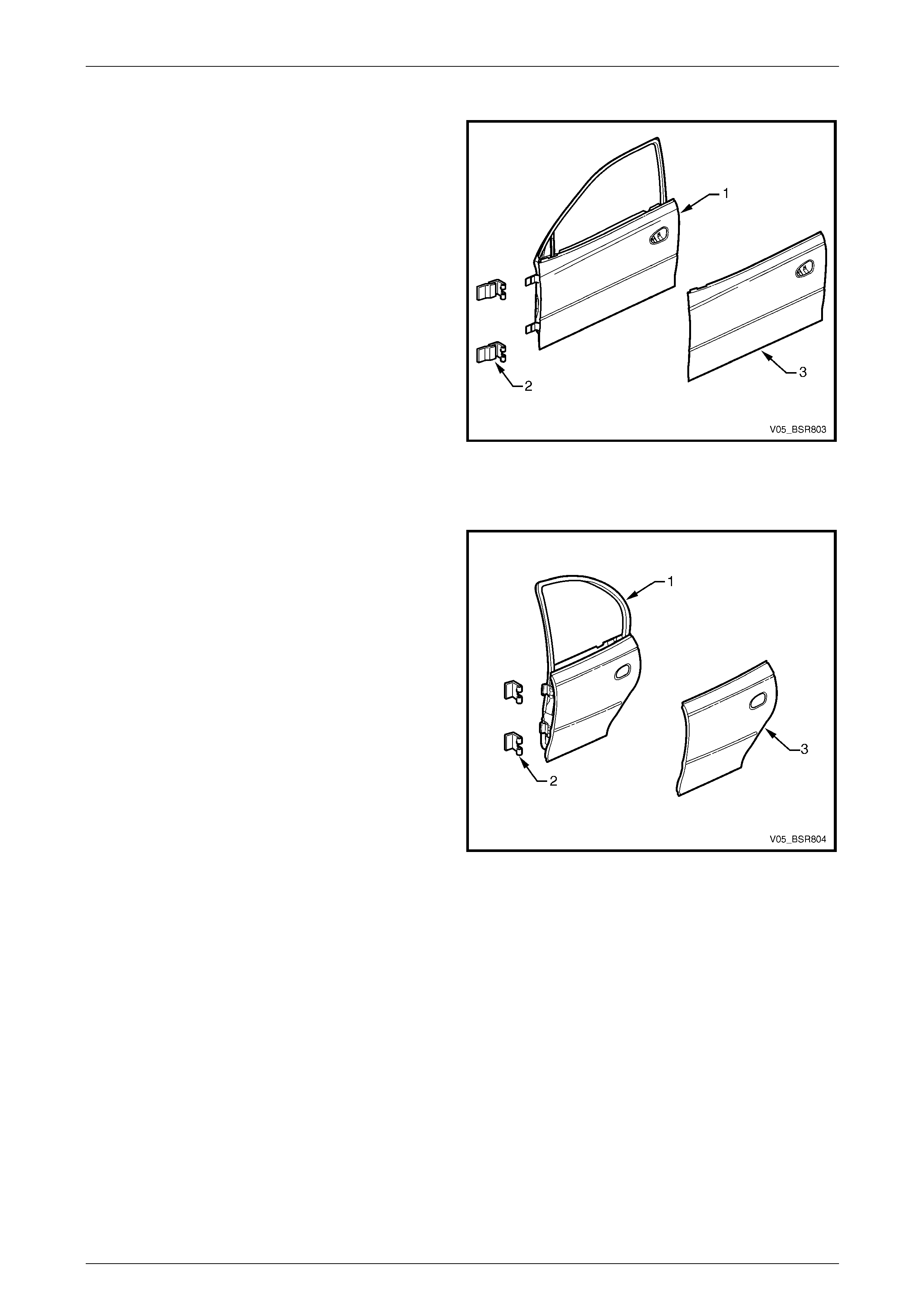
Front Door, Coupe
Legend
1 Front Door Assembly
2 Front Door Hinge (Body Side)
3 Front Door Outer Panel
Figure 8 – 2
Rear Door, Sedan
Legend
1 Rear Door Assembly
2 Rear Door Hinge (Body Side)
3 Rear Door Outer Panel
Figure 8 – 3
8 Doors, Liftgate and Endgate Page 8-5
Page 8-5
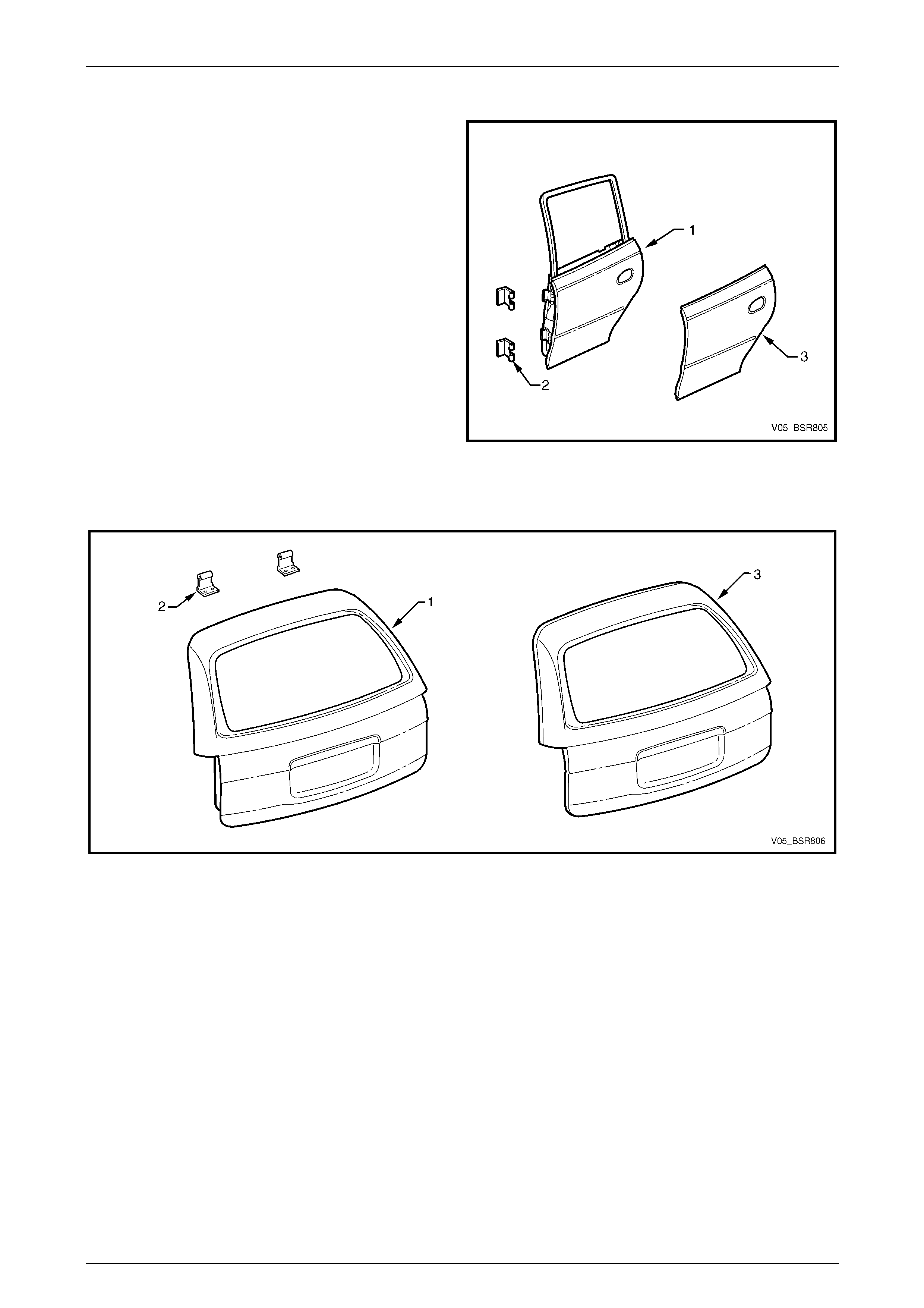
Rear Door, Wagon and Crew Cab
Legend
1 Rear Door Assembly
2 Rear Door Hinge (Body Side)
3 Rear Door Outer Panel
NOTE
The rear door assemblies fitted to Crew Cab
vehicles are unique in shape, however service
procedures are the same as the rear door
assemblies fitted to Wagon vehicles.
Figure 8 – 4
Liftgate, Wagon
Figure 8 – 5
Legend
1 Liftgate Assembly
2 Liftgate Hinge (Body Side) 3 Liftgate Outer Panel
8 Doors, Liftgate and Endgate Page 8-6
Page 8-6
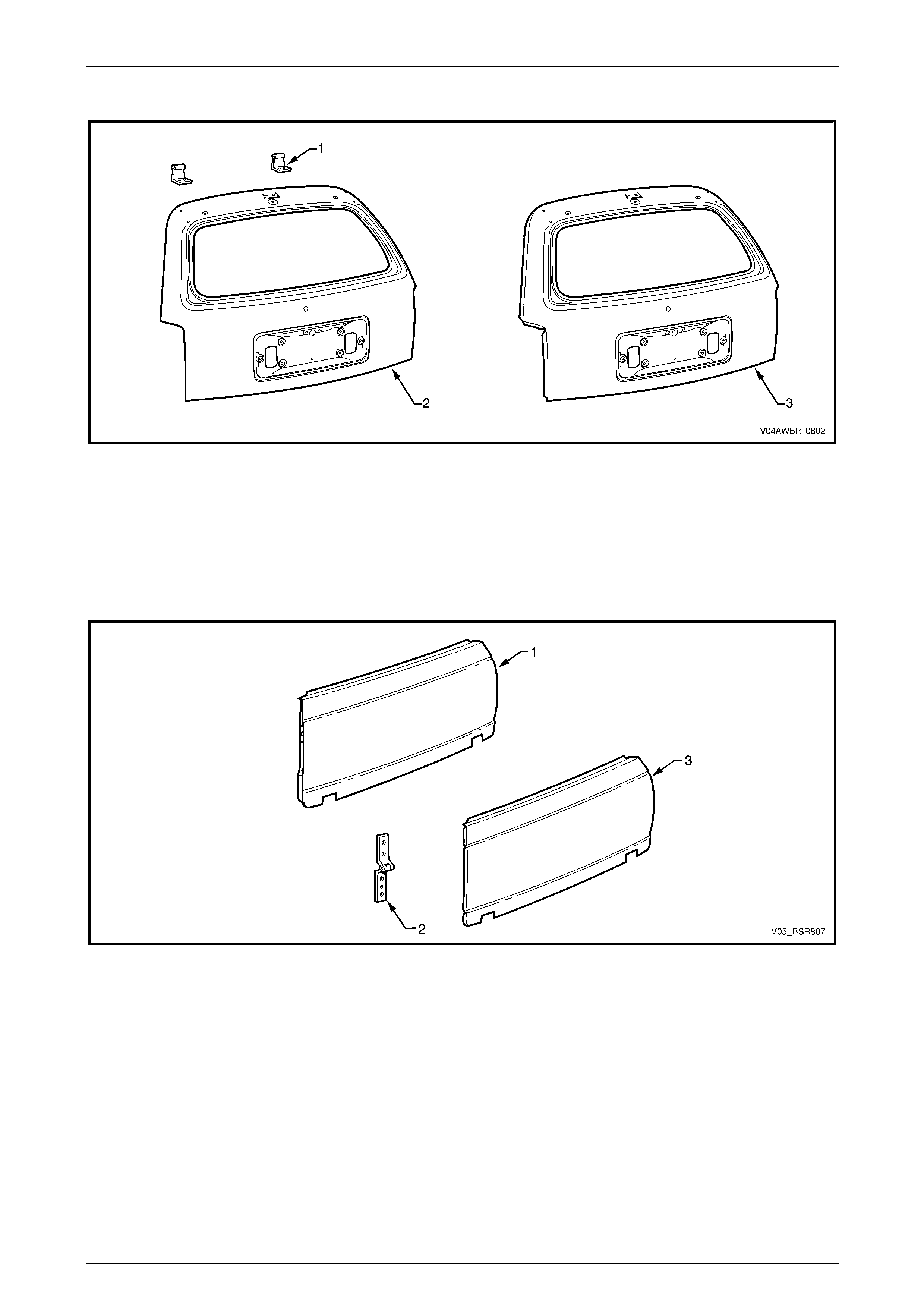
Liftgate, AWD Wagon
Figure 8 – 6
Legend
1 Liftgate Assembly
2 Liftgate Hinge (Body Side) 3 Liftgate Outer Panel
Endgate, Utility and Crew Cab
Figure 8 – 7
Legend
1 Endgate Assembly
2 Endgate Hinge Assembly 3 Endgate Outer Panel
8 Doors, Liftgate and Endgate Page 8-7
Page 8-7
2 Service Operations
2.1 Front Door Assembly – Replace
Remove
NOTE
Disassemble the door trim and hardware as
required. Refer to Section 1A5 Front and Rear
Door Assemblies in the MY 2005 VZ Service
Information.
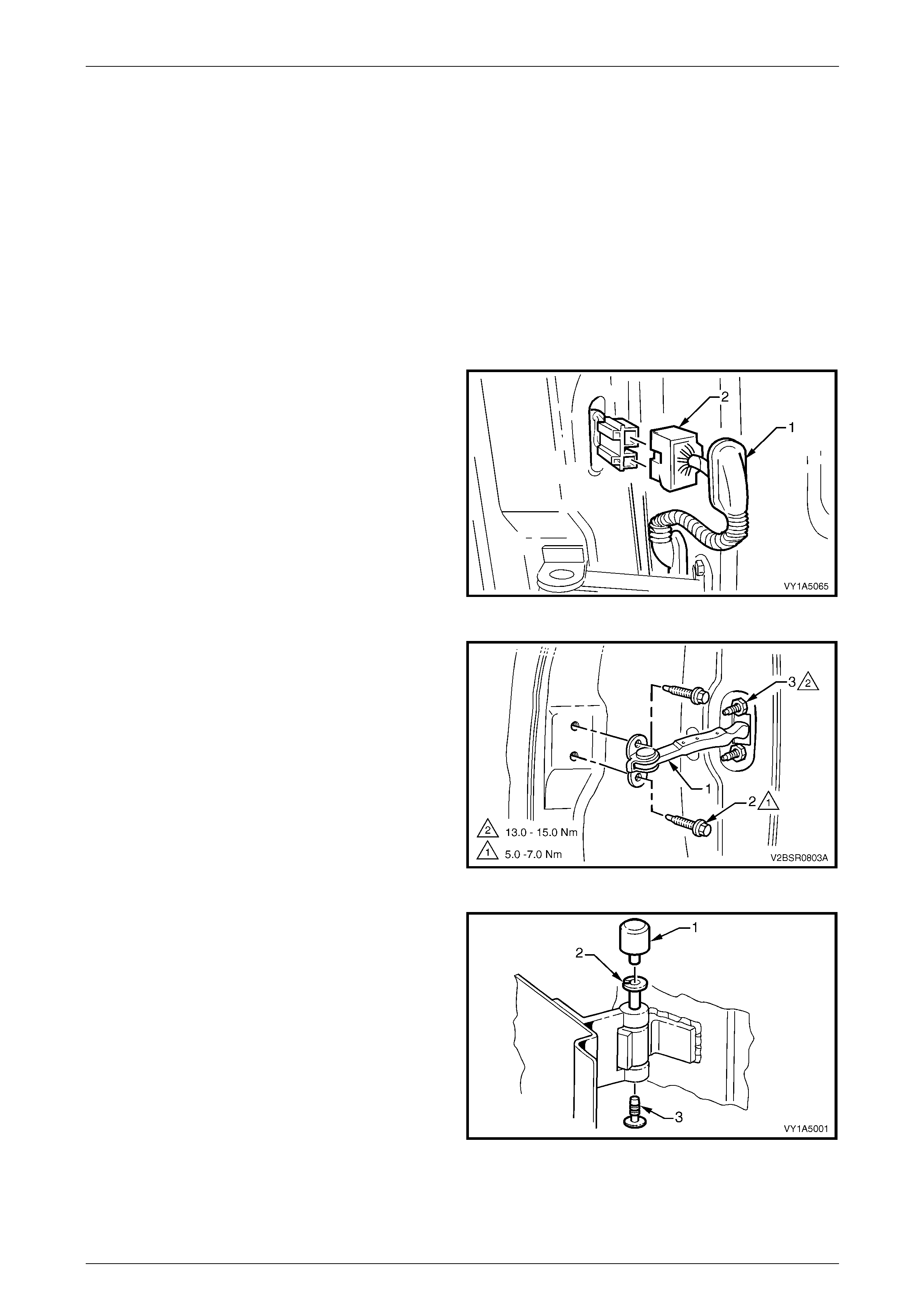
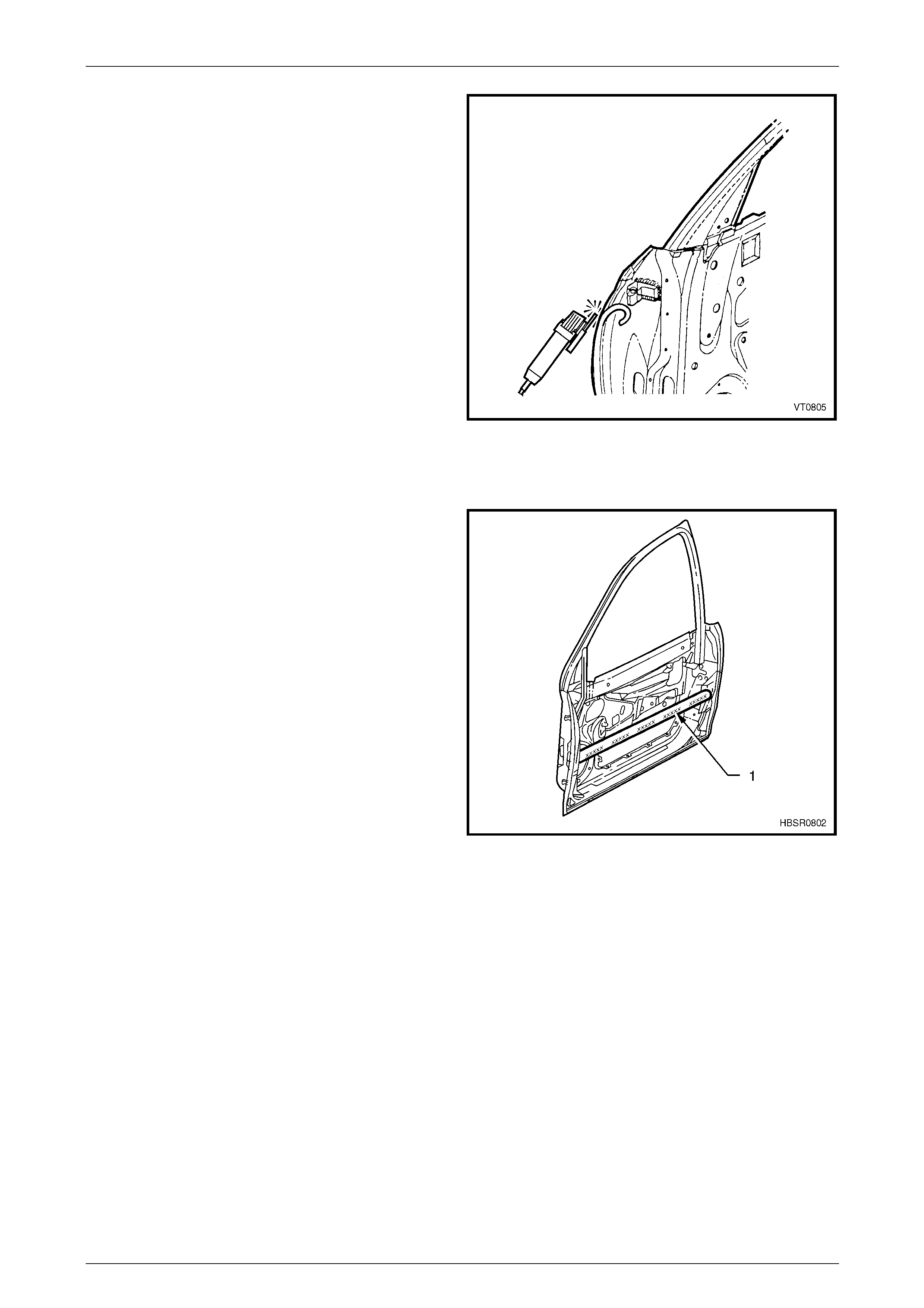
1 Remove the grommet (1) from the door wiring harness
connector plug (2).
2 Remove the connector plug from the pillar b y pushing
the tabs and gently pulling on the wiring harness and
then disconnect.
Figure 8 – 8
3 Disconnect the check assembly (1) from the vehicle by
removing the two screws (2).
NOTE
• If required, remove the two nuts (3),
attaching the check assembly to the door,
allowing access to the hinge pins.
• Ensure the door does not swing freely
causing damage.
Figure 8 – 9
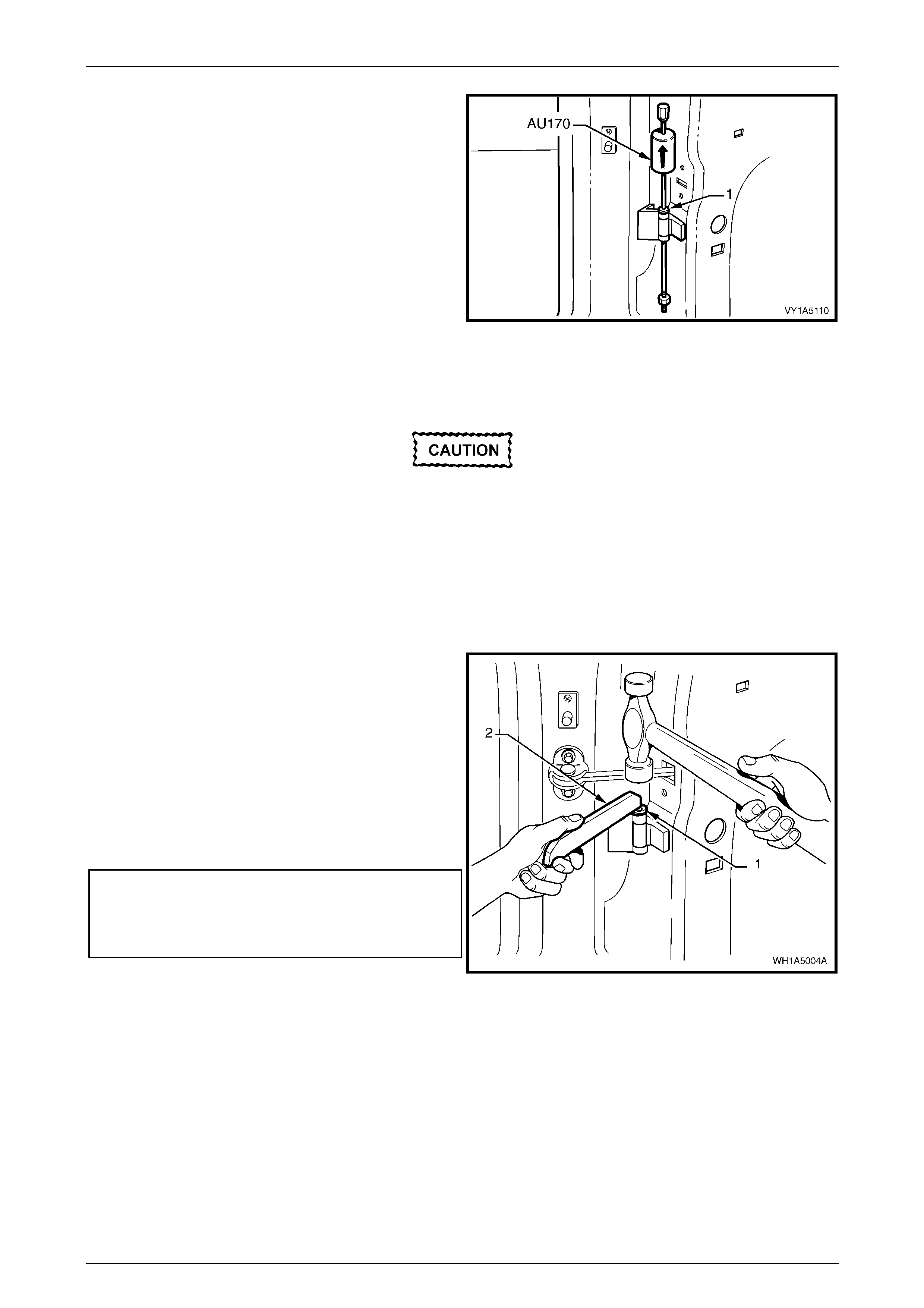
4 Remove the front hinge pin cap (1) an d the front hinge
plug (3) from the front hinge pin (2) on the upper an d
lower hinges.
5 Have an assistant support the door or sup port the
base of the door on a woode n block and a trolley jack.
Figure 8 – 10
8 Doors, Liftgate and Endgate Page 8-8
Page 8-8
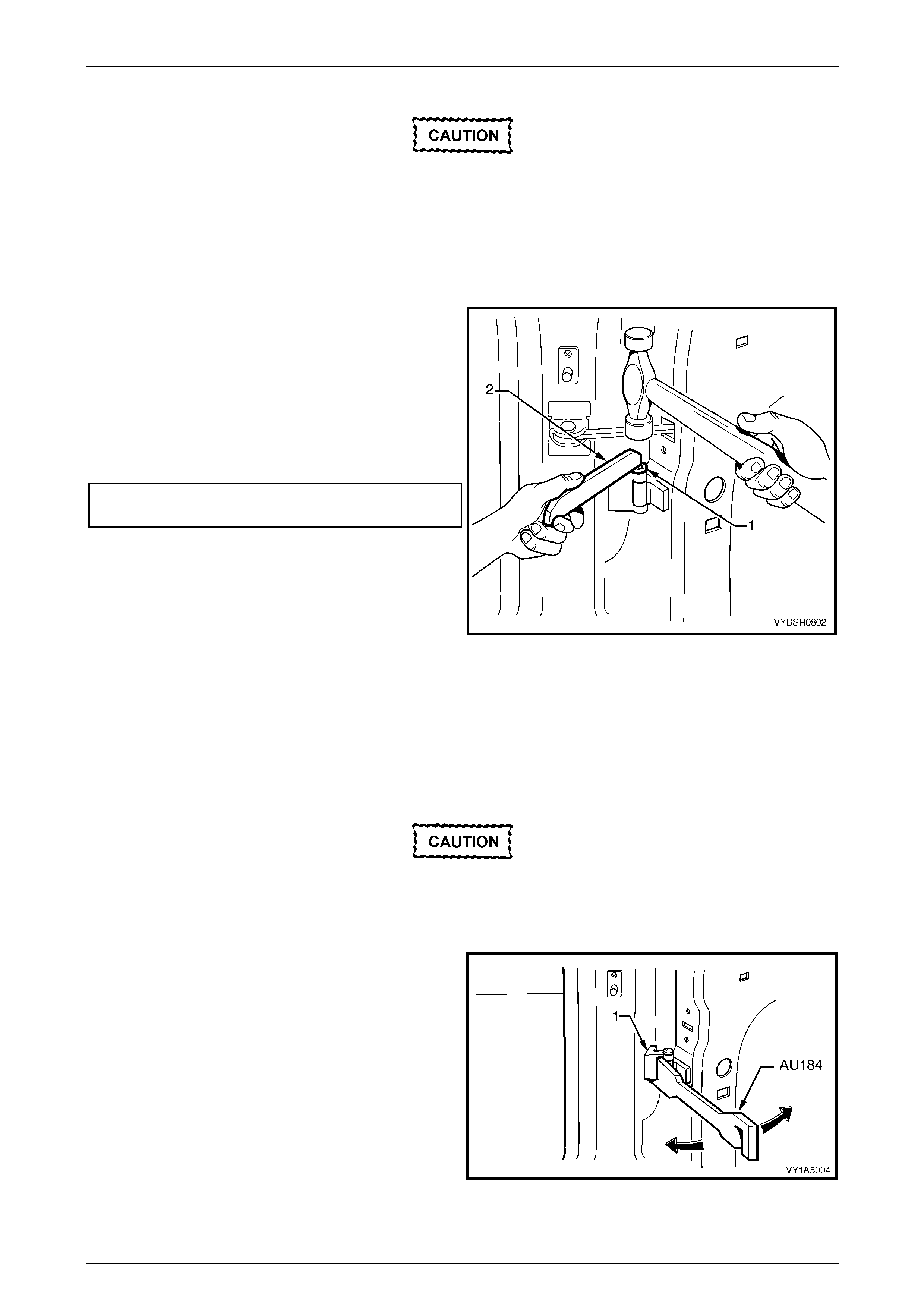
6 Using special tool No. AU170, drive the lower and then
the upper hinge pivot sleeves (1) from the hinges.
7 Remove the door assembly.
Figure 8 – 11
Reinstall
If installing a new door assembly it must be
prepared to maintain original manufacturer
specifications. This includes the application
of joint sealer, hand putty and cavity wax.
Refer to Section 3 Body Construction.
Reinstallation of the front door assembly is the reverse of the removal procedure, noting the following:
1 Apply a Lithium base grease NLGI No. 1 (with 9 % zinc oxide) or equivalent, to the hinge pivot sleeves prior to
installation.
2 Use special tool No. AU303 (2), to install the hinge
pivot sleeves (1).
3 Check the fit of the door and adjust as required,
referring below.
NOTE
Make allowances in the adjustment if the trim
and hardware are not installe d.
4 Tighten all retaining screws to the correct torque
specification.
Check assembly to pillar retaining screw
torque specification.....................................5.0 – 7.0 Nm
Check assembly to door retaining nuts
torque specification....................................... 13.0 – 15.0
5 Reinstall the trim and hardware as required. Figure 8 – 12
6 Connect and install the door wiring harness connector to the body wiring harness and refit the grommet.
7 Refit the hinge pivot sleeve dust caps, refer to Figure 8 – 8.
8 Doors, Liftgate and Endgate Page 8-9
Page 8-9
Adjust
Attention should be given to uniform margi ns and alignment between the door and surrounding parts when door
adjustments are being carried out.
Uniform margins and alignment of the doors in relation to the body opening can be achieved by setting the appropriate
door hinge. Refer to Section 3 Body Construction.
It is sound practice to remove the door lock striker assembly and allow the door to hang free on the hinges. Set the
hinges as necessary to achieve correct alignment and uniform margins, then reinstall and adjust the striker.
Adjust the doors with the striker assembly
removed. The striker assembly should only be
fitted once satisfactory alignment is a chieved.
It must not be used to pull the door into the
correct position.
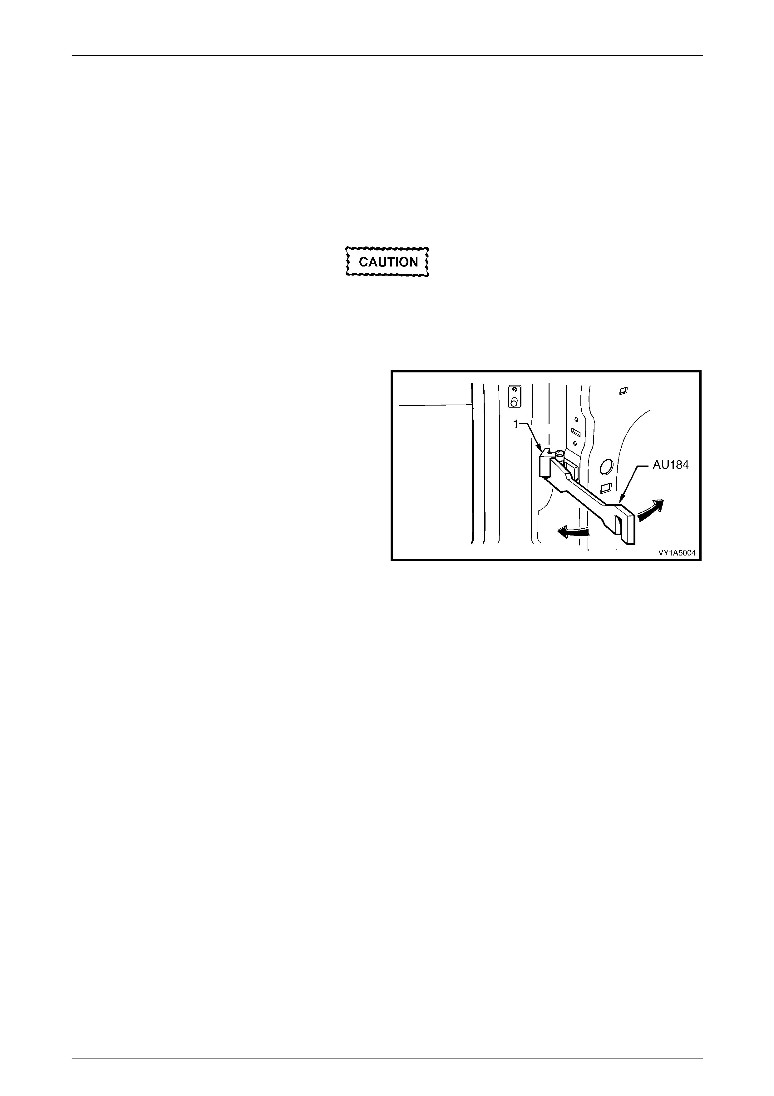
Use special tool No AU184 to set door hin ge s by slightly
bending the front door hinge (1) noting the following:
1 Take care when adjusting the doors not to misalign the
hinge pins. Any signific ant misalignment will cause the
pins to shear when the door is open ed or closed.
2 Excessive bending or lever ing of the window frame will
cause damage.
3 Final adjustment must take place when all the door
components and seals are installed.
Figure 8 – 13
8 Doors, Liftgate and Endgate Page 8-10
Page 8-10
2.2 Rear Door Assembly – Replace
Remove
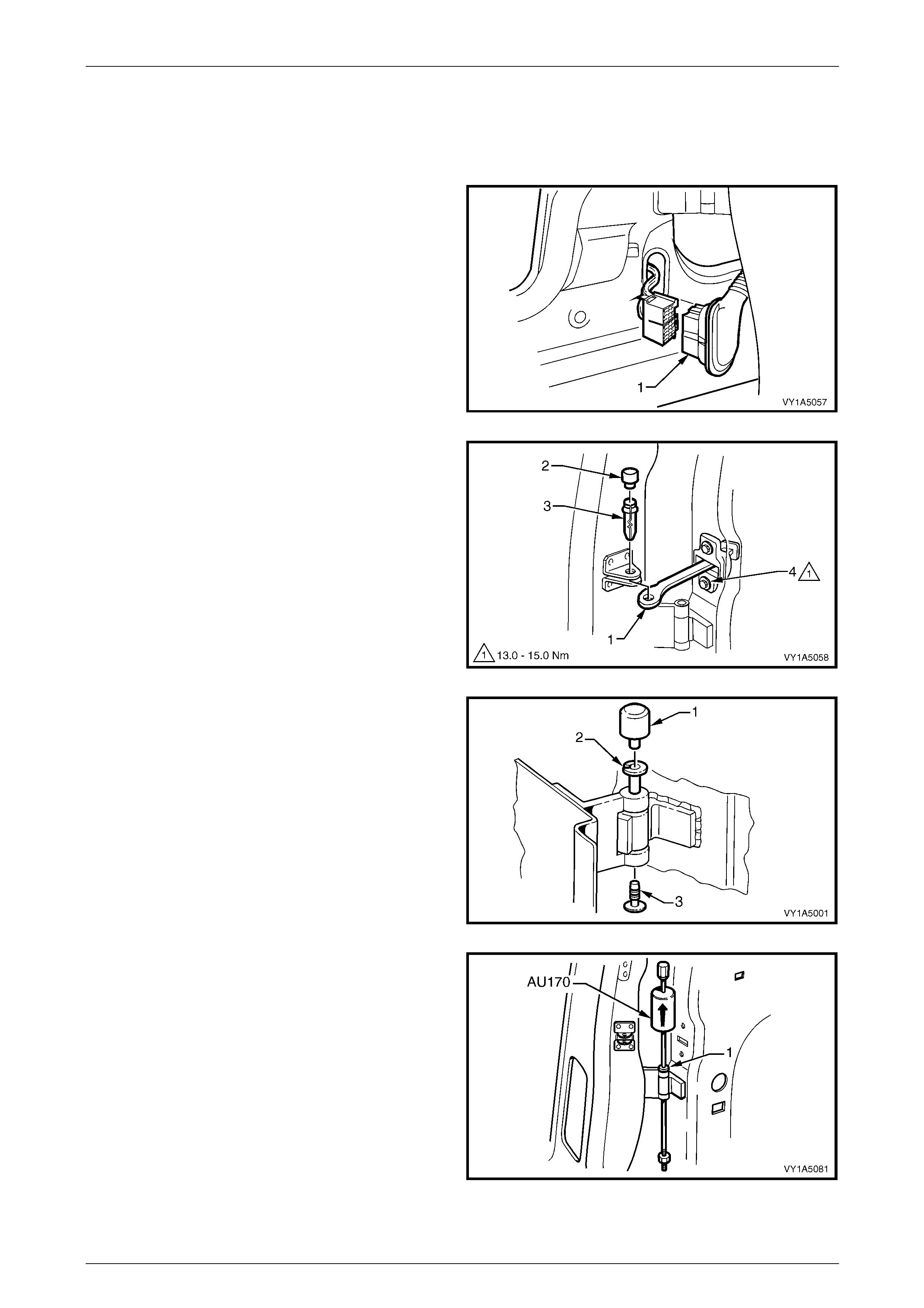
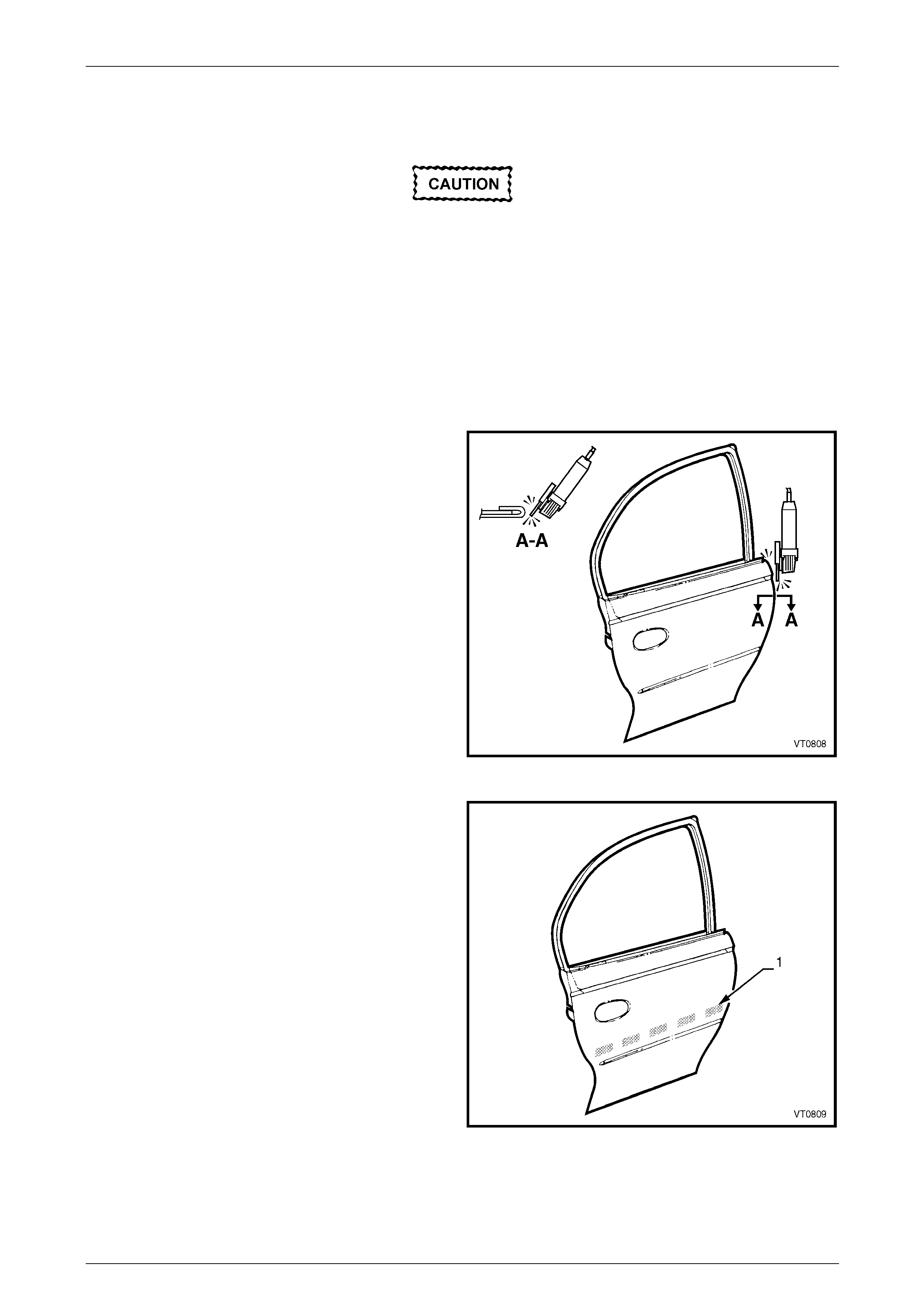
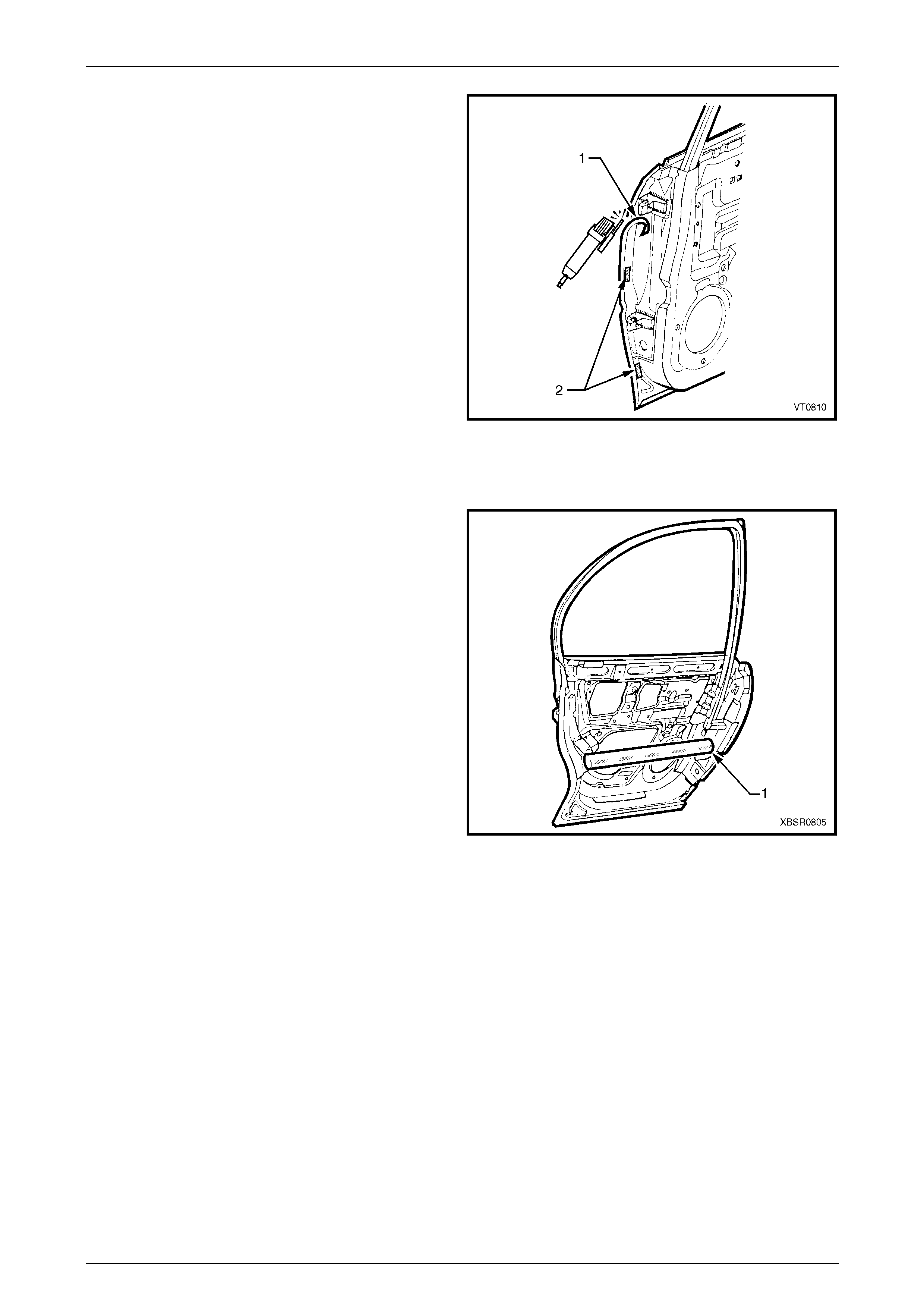
1 Remove the grommet and door wiring har ness
connector plug assembly (1).
2 Remove the connector plug from the pillar by gently
pulling on the wiring harness and then disconnect.
Figure 8 – 14
3 Disconnect the rear door check assembly (1) from the
vehicle, by removing the rear door check link bracket
cover (2) and then the rear door check link pin (3).
NOTE
• If required, remove the two screws (4)
attaching the check-link assembly to the do or
to allow access to the hinge pins.
• Ensure the door does not swing freely
causing damage.
Figure 8 – 15
4 Remove the rear hinge pin ca p (1) and the rear hinge
plug (3) from the rear hinge pin (2) on the upper and
lower hinges.
5 Have an assistant support the door or sup port the
base of the door on a woode n block and a trolley jack.
Figure 8 – 16
6 Using special tool No. AU170, drive the lower and then
the upper hinge pivot sleeves (1) from the hinges.
7 Remove the door assembly.
Figure 8 – 17
8 Doors, Liftgate and Endgate Page 8-11
Page 8-11
Reinstall
If installing a new door assembly it must be
prepared to maintain original manufacturer
specifications. This includes the application
of joint sealer, hand putty and cavity wax,
refer to Section 3 Body Construction.
Reinstallation of the front door assembly is the reverse of the removal procedure, noting the following:
1 Apply a Lithium base grease NLGI No. 1 (with 9 % zinc oxide) or equivalent, to the hinge pivot sleeves prior to
installation.
2 Use special tool No. AU303 (2), to install the hinge
pivot sleeves (1).
3 Check the fit of the door and adjust as required,
referring below. NOTE
Make allowances in the adjustment if the trim
and hardware are not installe d.
4 Tighten all retaining screws to the correct torque
specification.
Check assembly to door retaining screw
torque specification....................................... 13.0 – 15.0
5 Reinstall the trim and hardware as required.
6 Connect and install the door wiring harness connector
to the body wiring harness and refit the grommet.
7 Refit the hinge pivot sleeve dust caps, refer to
Figure 8 – 16.
Figure 8 – 18
Adjust
Attention should be given to uniform margi ns and alignment between the door and surrounding parts when door
adjustments are being carried out.
Uniform margins and alignment of the doors in relation to the body opening can be achieved by setting the appropriate
door hinge. Refer to Section 3 Body Construction.
It is sound practice to remove the door lock striker assembly and allow the door to hang free on the hinges. Set the
hinges as necessary to achieve correct alignment and uniform margins, then reinstall and adjust the striker.
Adjust the doors with the striker assembly
removed. The striker assembly should only be
fitted once satisfactory alignment is a chieved.
It must not be used to pull the door into the
correct position.
Use special tool No AU184 to set door hin ge s by slightly
bending the front door hinge (1) noting the following:
1 Take care when adjusting the doors not to misalign the
hinge pins. Any signific ant misalignment will cause the
pins to shear when the door is open ed or closed.
2 Excessive bending or lever ing of the window frame will
cause damage.
3 Final adjustment must take place when all the door
components and seals are installed.
Figure 8 – 19
8 Doors, Liftgate and Endgate Page 8-12
Page 8-12
2.3 Door Hinge (Body Side) – Replace
Remove
1 Remove the appropriate door from vehicle as previously described.
2 Carefully grind the MIG weld from around the hinge flap.
3 Remove the hinge and gr ind any remaining MIG weld as required.
NOTE
Do not cut into the door opening frame pane l.
Reinstall
1 Remove any trim and components from behind the pillar area as required. Refer to the appropriate Sections in the
MY 2005 VZ Service Information.
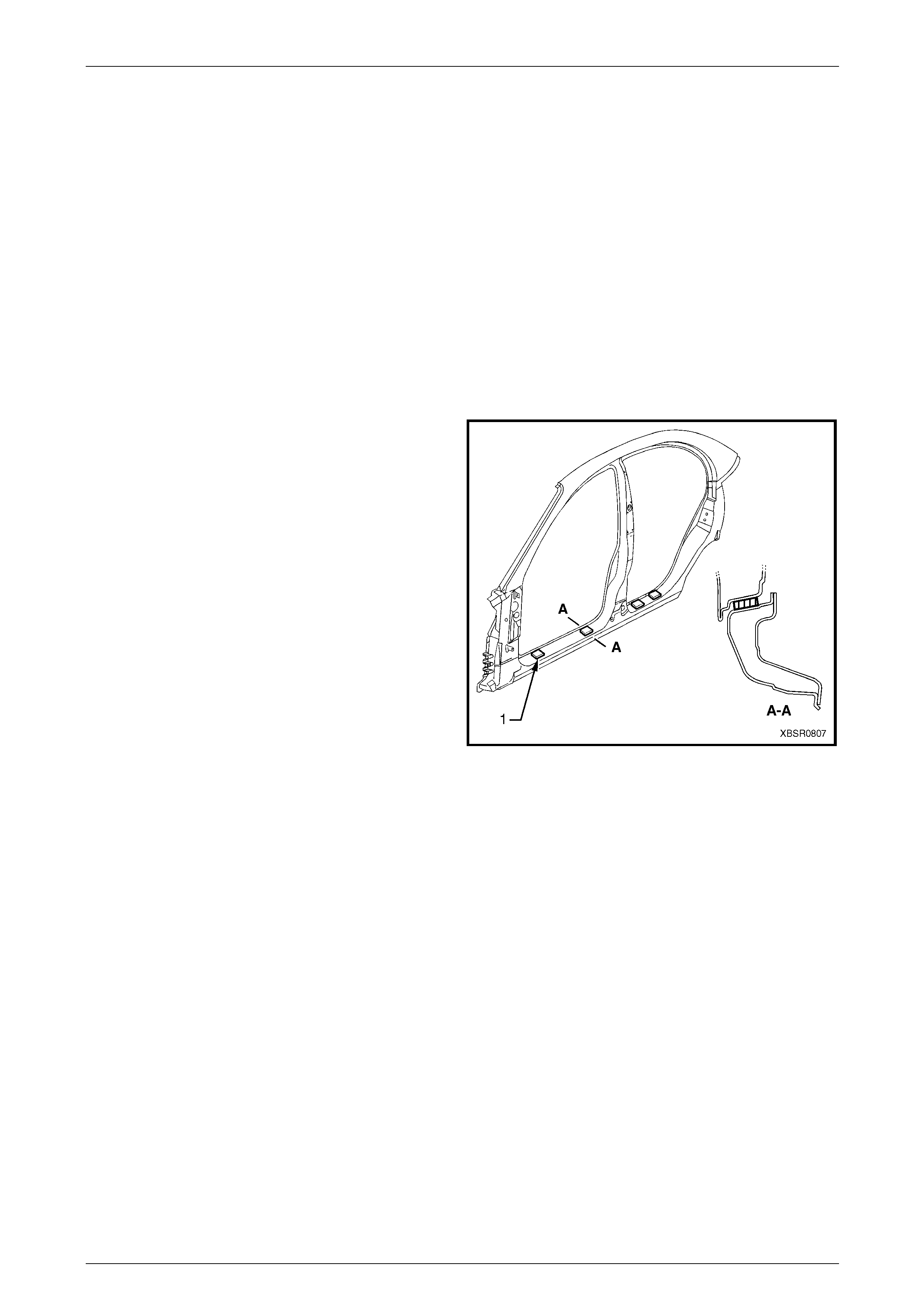
2 Construct two spacers (1) from timber, 10 mm thick.
3 Tape the spacers in the positions shown near the
dimples in the flange of the rocker panel, either for the
front or rear doors.
NOTE
If both front and rear door hinge flaps require
replacing, begin with the rear door.
4 If not already done so, fit the hinge flaps ont o the door
assembly.
5 With the aid of an assistant, place the
door assembly in position on the vehicle and
adjust its position with shims as required.
Refer to Section 3 Body Construction for
specifications.
Figure 8 – 20
NOTE
Position the rear of the door approximately 3 mm
higher than specified to allow for the additional
weight of the door hardware and trim
components.
8 Doors, Liftgate and Endgate Page 8-13
Page 8-13
6 Tack weld the upper and lo wer hinge flaps to the do or opening frame assembly.
7 Remove the spacer blocks and shims and recheck the door alignment. Rectify as required.
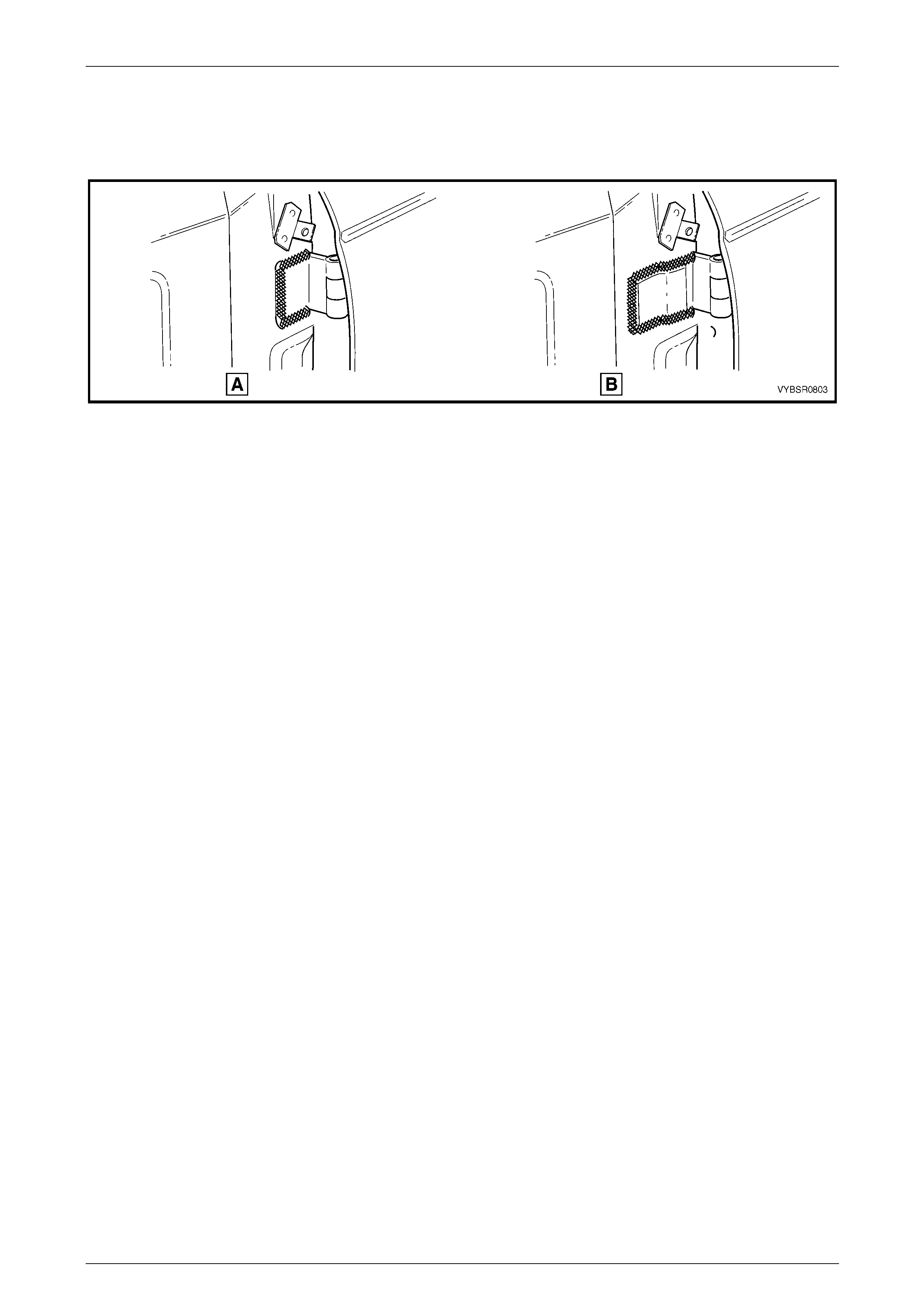
8 Complete welding the hinge fl ap, refer to F igure 8 – 21, A – except Coupe, or B – Coupe.
Figure 8 – 21
9 Remove the door assembly from the hinge as previously described.
10 Grind or sand the weld to provide a smooth finish.
11 Refinish and paint the hinge flaps and surrounding area as required. Refer to Section 3 Body Constructio n.
12 Apply a smooth bead of Joint Sealer (Item 3) around all sides of the flap before the top paint coats to maintain
corrosion protection under the flap, refer to Section 3 Body Constructi on .
13 Apply Cavity Wax (Item 8) as required to the inside of any box secti ons or areas inaccessible to paint,
refer to Section 3 Body Construction.
8 Doors, Liftgate and Endgate Page 8-14
Page 8-14
2.4 Front Door Outer Panel – Replace
The door impact beams must not be heated,
welded or straightened in any way, due to
their critical role in driver/passenger safety.
Damage to the impact beams will necessitate
the replacement of the entire door assembly.
Remove
1 Disassemble the door trim and hardware as required. Refer to Section 1A5 Front and Rear Door Assemblies in the
MY 2005 VZ Service Information.
2 Remove the front door from the vehicle, refer to 2.1 Front Door Assembly – Replace.
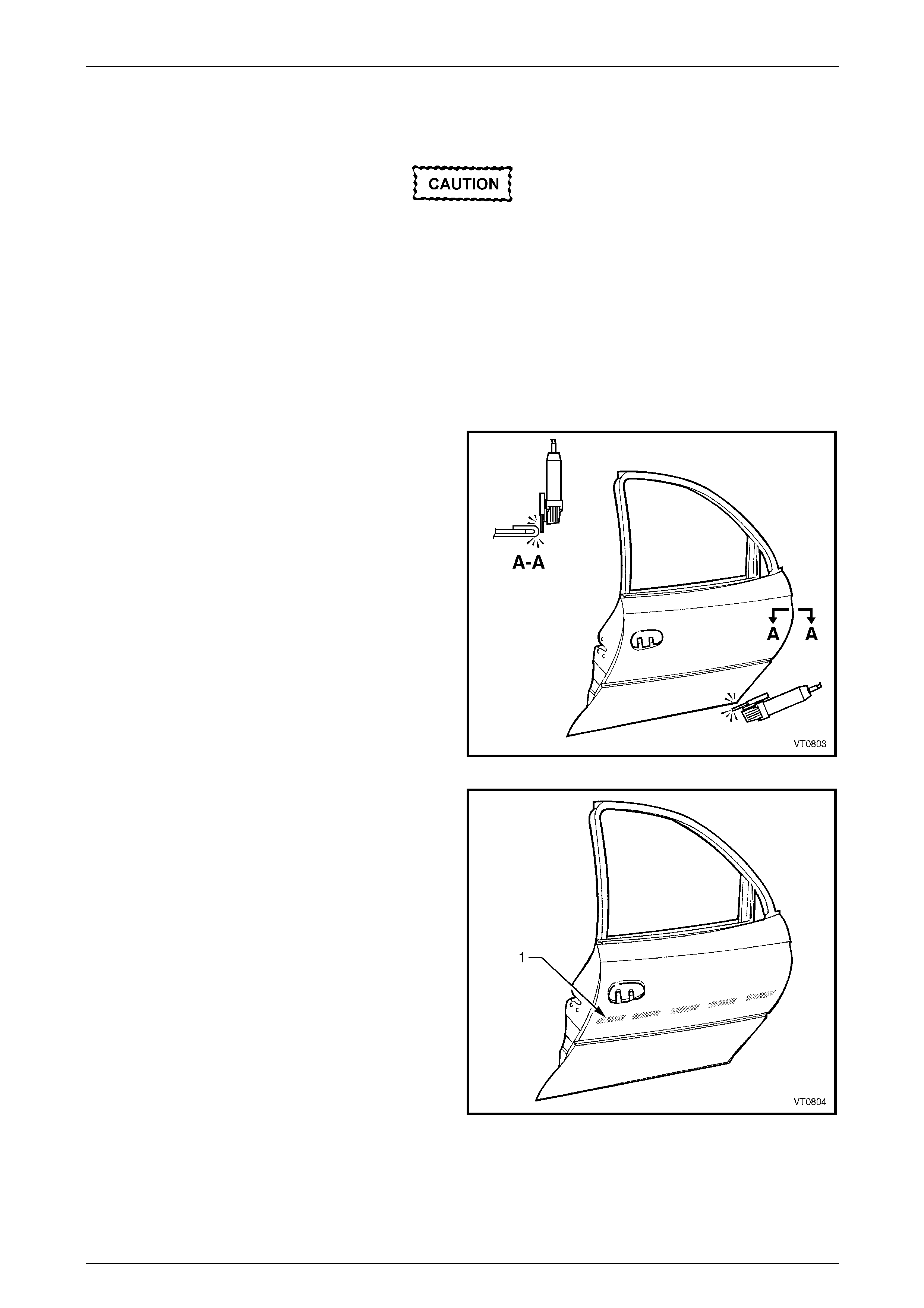
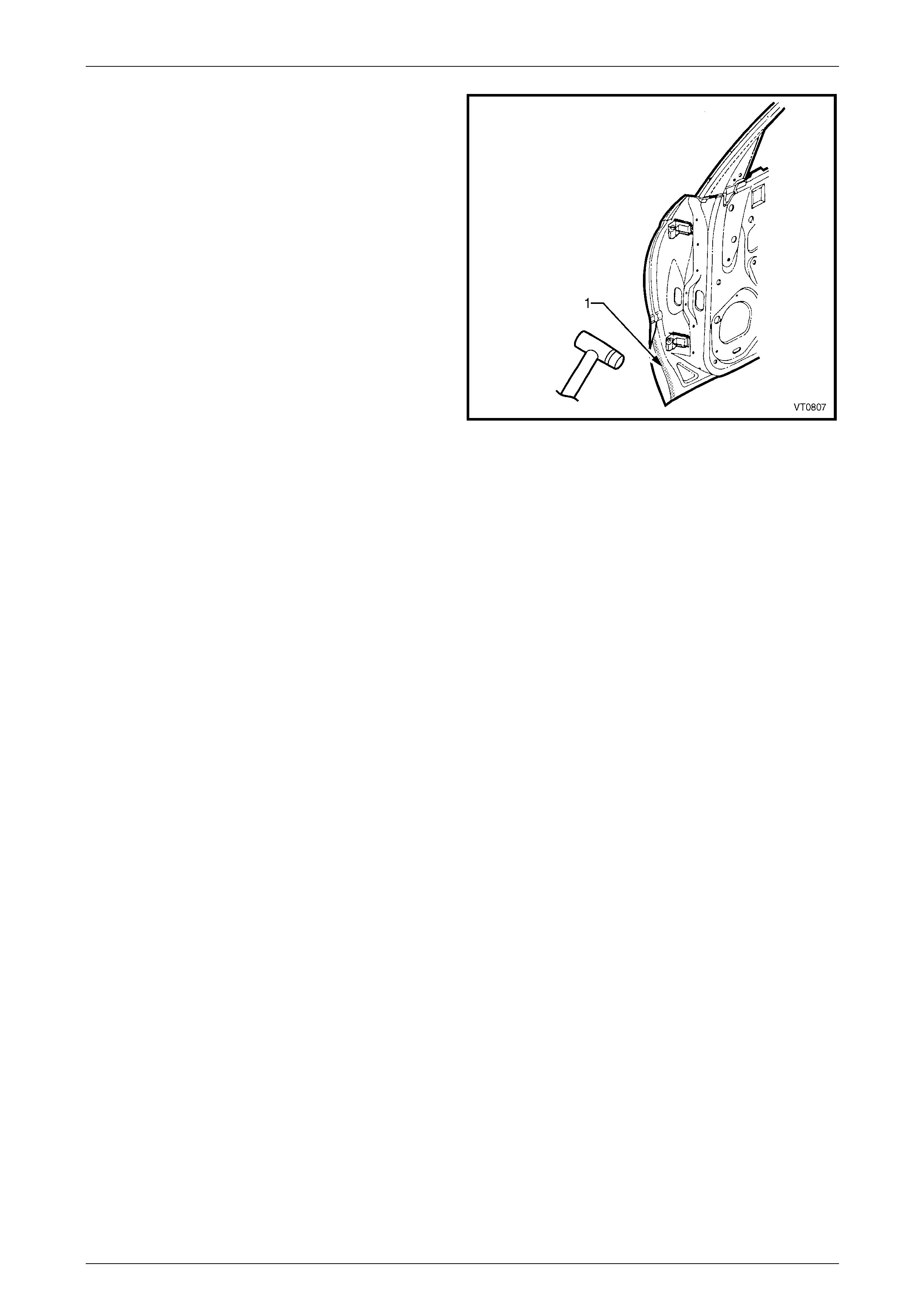
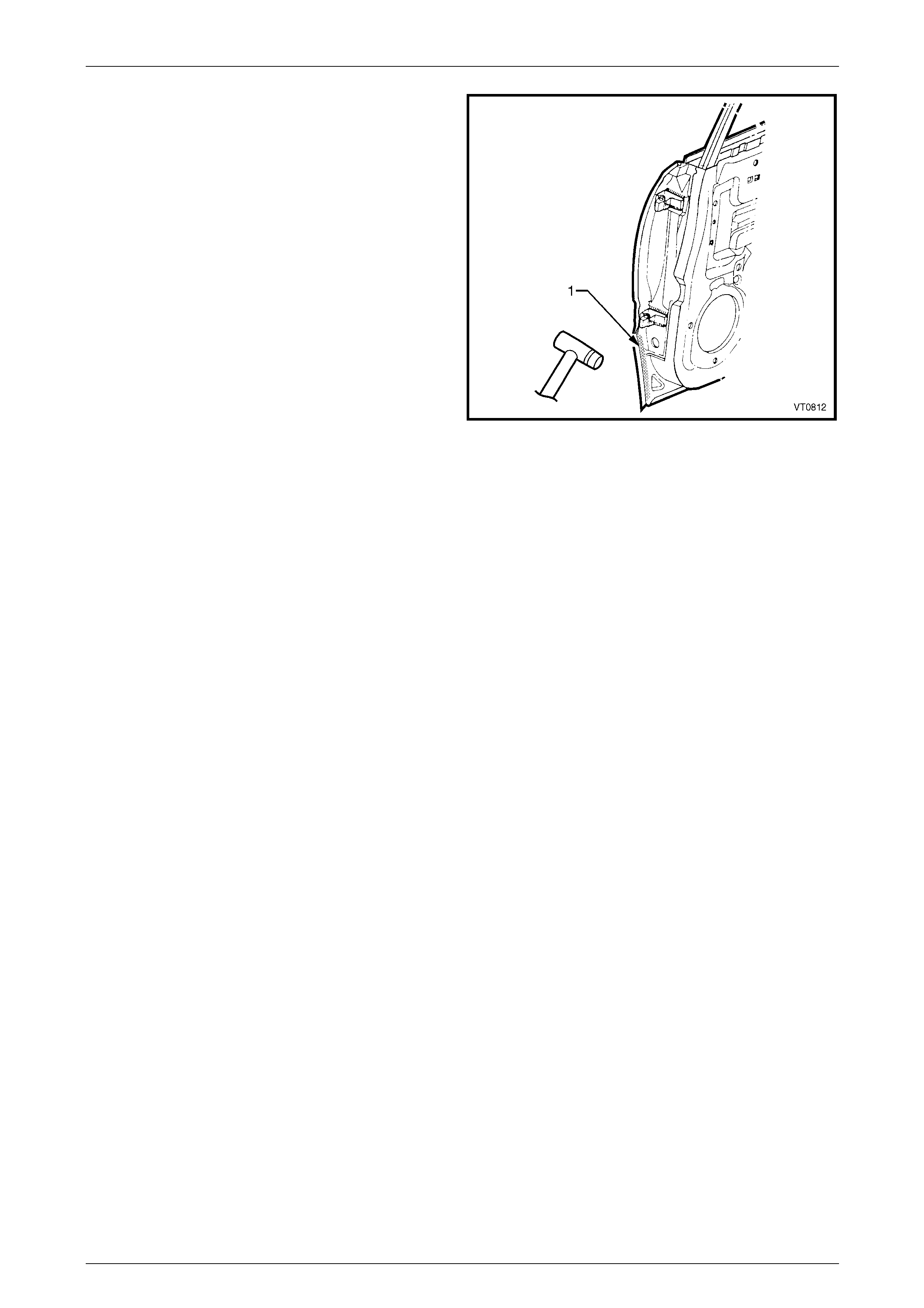
3 Remove the edge of the hem by grindin g or sand ing,
along the front, rear and lower edges of the door.
Figure 8 – 22
4 Soften the adhesive between the door outer panel and
the door impact beam using a heat gun in the areas
(1).
5 Separate the door outer panel from the door inner.
Figure 8 – 23
8 Doors, Liftgate and Endgate Page 8-15
Page 8-15
6 Remove the hemming strip from the door inn er pan el
by grinding or chiselling away the metal and the
adhesive.
7 Repair any damage to the door inner panel as
required. Remove any residual adhesive from the hem
and door impact beam.
8 Prepare and prime and bare metal.
9 Test fit the door inner panel onto the vehicle.
Figure 8 – 24
Replace
1 Apply five equally spaced beads (1) of Anti-flutter
Adhesive (Item 5) to the impact beam, refer to
Section 3 Body Construction.
Figure 8 – 25
8 Doors, Liftgate and Endgate Page 8-16
Page 8-16
2 Apply Structural Adhesive (1) (Item 6) to the mating
surfaces around the hem on the door inner pane l,
refer to Section 3 Body Construction.
3 Clamp the outer panel in position and fold over the
hemming to attach the outer panel firmly to the inner
shell.
NOTE
This procedure must be performed carefully to
avoid damaging the panel surface. The use of
body filler around the outer edges of the door
outer panel to rectify hammering damage is
considered unacceptable.
4 Test fit the door onto the vehicle and ensure
the panel margins are within specification,
refer to Section 3 Body Construction.
5 Remove the door.
6 Refinish and paint the door as required.
Refer to Section 3 Body Construction. Figure 8 – 26
7 Apply Joint Sealer (Item 3) as required. Refer to Section 3 Body Construction.
8 Apply Cavity Wax (Item 8) as required to the inside of any box sections or areas inaccessible to paint,
refer to Section 3 Body Construction.
9 Install the door onto the vehicle and adjust as required, refer to 2.1 Front Door Assembly – Replace.
10 Replace the door trim and hardware as required. Refer to Section 1A5 Front and Rear Door Assemblies in the MY
2005 VZ Service Information.
8 Doors, Liftgate and Endgate Page 8-17
Page 8-17
2.5 Rear Door Outer Panel – Replace
The door impact beams must not be heated,
welded or straightened in any way, due to
their critical role in driver/passenger safety.
Damage to the impact beams will necessitate
the replacement of the entire door assembly.
Remove
1 Disassemble the door trim and hardware as required. Refer to Section 1A5 Front and Rear Door Assemblies in the
MY 2005 VZ Service Information.
2 Remove the rear door from the vehicle, refer to 2.2 Rear Door Assembly – Replace.
3 Remove the edge of the hem by grindin g or sand ing,
along the front, rear and lower edges of the door.
Figure 8 – 27
4 Soften the adhesive between the door outer panel and
the door impact beam using a heat gun in the areas
(1).
5 Separate the door outer panel from the door inner.
Figure 8 – 28
8 Doors, Liftgate and Endgate Page 8-18
Page 8-18
6 Remove the hemming strip (1) from the door inner
panel by grinding or chiselling away the metal strip
and the adhesive.
NOTE
There are two tack welds (2) attaching the
hemming to the door inner panel on the front
edge of the rear door. These welds must be
ground off to remove the hemming from this
area.
7 Repair any damage to the door inner panel as
required. Remove any residual adhesive from the hem
and door impact beam.
8 Prepare and prime and bare metal.
9 Test fit the door inner panel onto the vehicle.
Figure 8 – 29
Replace
1 Apply five equally spaced beads (1) of Anti-flutter
Adhesive (Item 5) to the impact beam, refer to
Section 3 Body Construction.
Figure 8 – 30
8 Doors, Liftgate and Endgate Page 8-19
Page 8-19
2 Apply Structural Adhesive (1) (Item 6) to the mating
surfaces around the hem on the door inner, refer to
Section 3 Body Construction.
3 Clamp the outer panel in position and fold over the
hem to attach the outer panel firmly to the inner panel.
NOTE
This procedure must be performed carefully to
avoid damaging the panel surface. The use of
body filler around the outer edges of the door
outer panel to rectify hammering damage is
considered unacceptable.
Figure 8 – 31
4 Test fit the door onto the vehicle and ensure the panel margins are within specification,
refer to Section 3 Body Construction.
5 Remove the door.
6 Place two MIG tack welds attaching the front hemming to the door inner panel.
NOTE
Place several wet rags on the surrounding
surface and the outer panel to minimise heat
distortion.
7 Refinish and paint the door as required. Refer to Section 3 Body Construction.
8 Apply Joint Sealer (Item 3) as required. Refer to Section 3 Body Construction.
9 Apply Cavity Wax (Item 8) as required to the inside of any box sections or areas inaccessible to paint,
refer to Section 3 Body Construction.
10 Install the door onto the vehicle and adjust as required, refer to 2.2 Rear Door Assembly – Replace.
11 Install the door trim and hardware as requir ed. Refer to Section 1A5 F r ont and Rear Door Assemblies in the MY
2005 VZ Service Information.
8 Doors, Liftgate and Endgate Page 8-20
Page 8-20
2.6 Liftgate Assembly – Replace
Remove
1 Disassemble the tailgate trim and hardware as required,
refer to Section 1A4 Hood, Rear Compartment Lid, Liftgate and Endgate in the MY 2005 VZ Service Informatio n.
2 Remove the liftgate window, refer to Section 1A6 Stationary Windows in the MY 2005 VZ Service Information.
3 Partially remove the right-han d quarter inner trim
upper refer to Section 1A8 Headlin ing and Interior
Trim in the MY 2005 VZ Service Information.
4 Partially remove the right-hand body rear corner
garnish, refer to Section 1A8 Headlining an d Interior
Trim in the MY 2005 VZ Service Information.
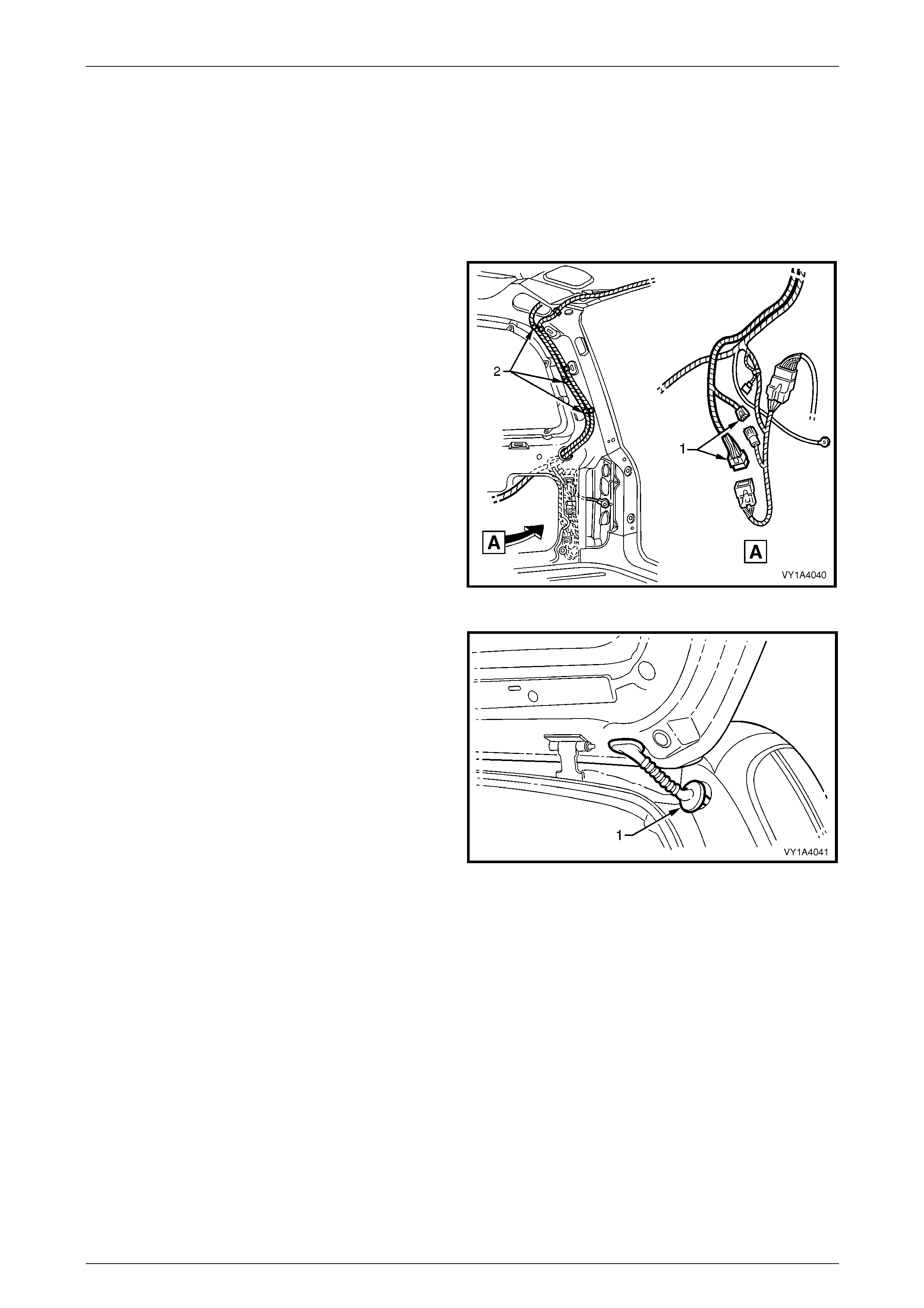
5 Disconnect the two liftgate assembly wiring harness
connectors (1).
6 Unclip the liftgate harness, three places (2).
Figure 8 – 32
7 Remove the right-hand grommet (1) from the vehicle
and withdraw the harness fro m the pillar cavity.
8 Remove the left-hand grommet from the liftgate and
withdraw the washer hose through the liftgate cavity.
Figure 8 – 33
8 Doors, Liftgate and Endgate Page 8-21
Page 8-21
9 Complete either step 10 or 11:
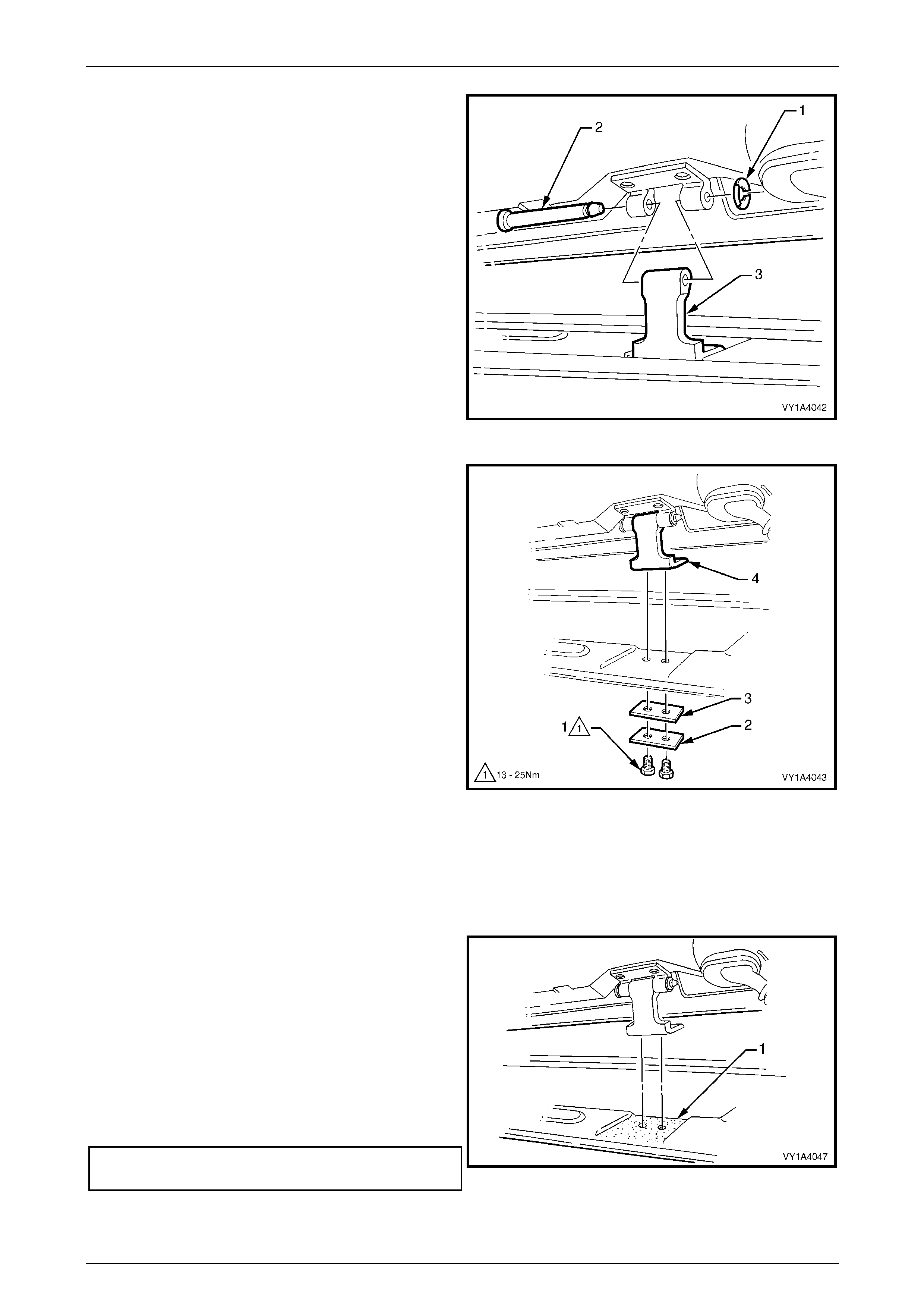
10 Remove the liftgate assembly:
a Remove the liftgate hinge pin retain er (1) from
each side of the vehicle.
b Have an assistant hold the ot her side of the
liftgate and withdraw each liftgate hinge pin (2).
c Remove the liftgate assembly leaving the liftgate
hinge (body side) (3) in position.
Figure 8 – 34
10 Remove the liftgate assembly:
a Remove the rear window upper garnish, refer to
Section 1A8 Headlining and Interior Trim in the
MY 2005 VZ Service Information.
b Remove the two screws (1), plate (2) and seal
(3).
c Remove the liftgate assembly with the liftgat e
hinge (body side) (4).
Figure 8 – 35
Reinstall
Installation is the reverse of removal noting the following.
1 If the liftgate was removed from the liftgate hinge pin, lubricate the pin with lithium based grease prior to installation.
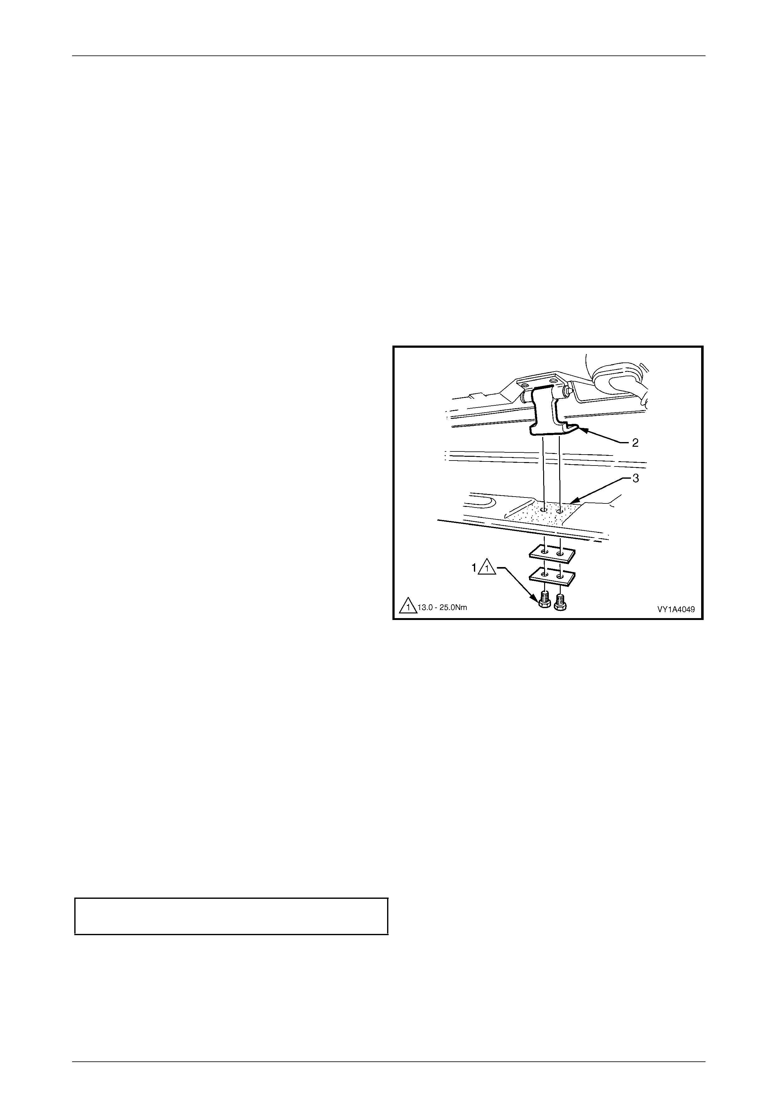
2 If the liftgate was removed with the liftgate hinge (body
side), apply sealer such as Lo rd F usor #800 or #801
or equivalent to the area shown (1).
3 Set the two bumpers to the full-in position then adjust
to achieve the required alignment of the liftgate, refer
to the following adjustment procedure.
4 Test the operation of the wiper, washer, high mount
stop lamp, rear compartment courtesy lamp s witch
and lock mechanism before installing the trim pane ls.
5 Tighten all screws to the specified torque.
Liftgate Hinge (Body Side) Attaching
Screw Torque Specification ....................13.0 – 25.0 Nm Figure 8 – 36
8 Doors, Liftgate and Endgate Page 8-22
Page 8-22
Adjust
Correct alignment of the liftgate is critical to it s operation and to the aesthetics of the vehicle. T he following components
allow adjustment of the liftgate:
• Liftgate bumper: Provides adjustment at the outer area of the liftgate assembly.
• Liftgate hinge (body side) screws: Provide forward, rearward and ske w adjustment of the liftgate assembly.
• Liftgate striker assembly: Provides vertical and sideways adjustment of the liftgate assembly.
Whenever alignment is required, perform adjustment in the following order.
1 If fitted, remove the liftgate striker assembly.
2 Ensure the liftgate weatherstrip assembly is installed and the liftgate bumpers are fitted and set fully in.
3 Carefully close the liftgate, watching the top and each side does n ot contact the vehicle.
4 Check the alignment of the liftgate for width and co nsistency of gap to the roof panel, qu arter panel each side, tail
lamps and rear bumper fascia, refer to Section 3 Body Construction for specifications.
5 If the gap between the liftgate and roof panel is not
within specification an d/or is not parallel to the quarter
panel each side, open the liftgate and ad just the
position of the liftgate hinge(s):
• Remove the rear window upper garnish if not already
done, refer to Section 1A8 Headlin ing and Interior Trim
in the MY 2005 VZ Service Information.
• Loosen the two screws (1) attaching the l iftgate hinge
(2).
• Lift the hinge away from the body and appl y sealer
such as Lord Fusor #800 or #801 or equ ivalent to the
area shown (3).
• Adjust the position of the hinge, tighten the s crews and
recheck the liftgate alignment.
Figure 8 – 37
NOTE
Do not make all adjustments at once. Perform
one adjustment, carefully c lose the liftgate, check
its position and make further adjustments until
correct alignment is achieved .
6 If the gap between the liftgate and roof panel is within specificatio n and the liftgate is parallel to the quarter panel
each side, open the liftgate and adjust the liftgate bumpers to provide a slightly greater gap at the lower edge of the
liftgate above each tail lamp. This allo ws for the striker to pull the liftgate in slightly when closed.
7 Install the liftgate striker assembly.
8 Close the liftgate, watching that the striker does not pull the liftgate to one side, changing the panel gaps. If it does,
move the striker as required.
9 Tighten all screws to their specified torque.
Liftgate Hinge (Body Side)Attaching Screw
Torque Specification ...............................13.0 – 25.0 Nm
8 Doors, Liftgate and Endgate Page 8-23
Page 8-23
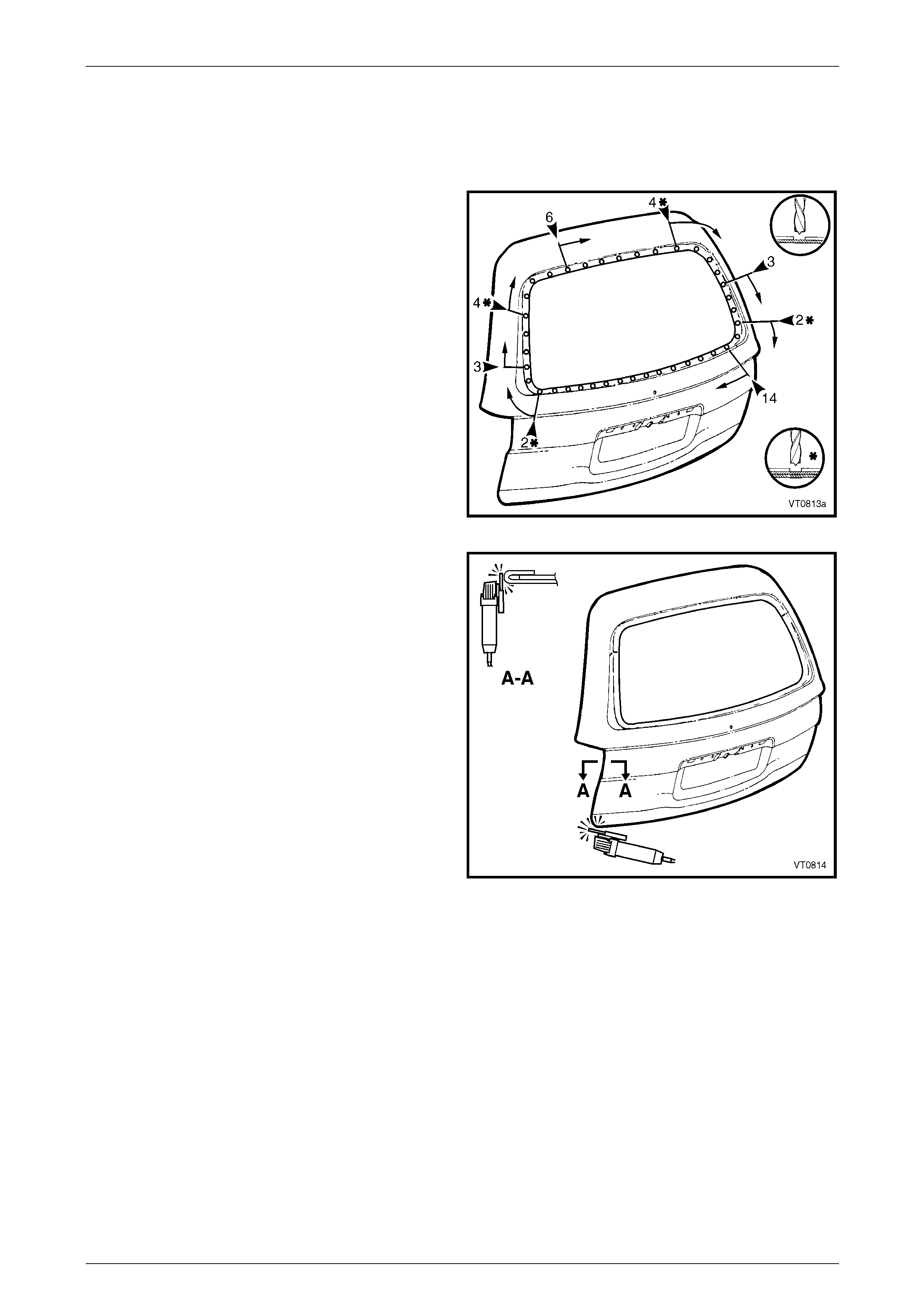
2.7 Liftgate Outer Panel, except AWD Wagon
– Replace
Remove
1 Remove the tailgate from the vehicle as d escribe d in
2.6 Liftgate Assembly – Replace in this Section.
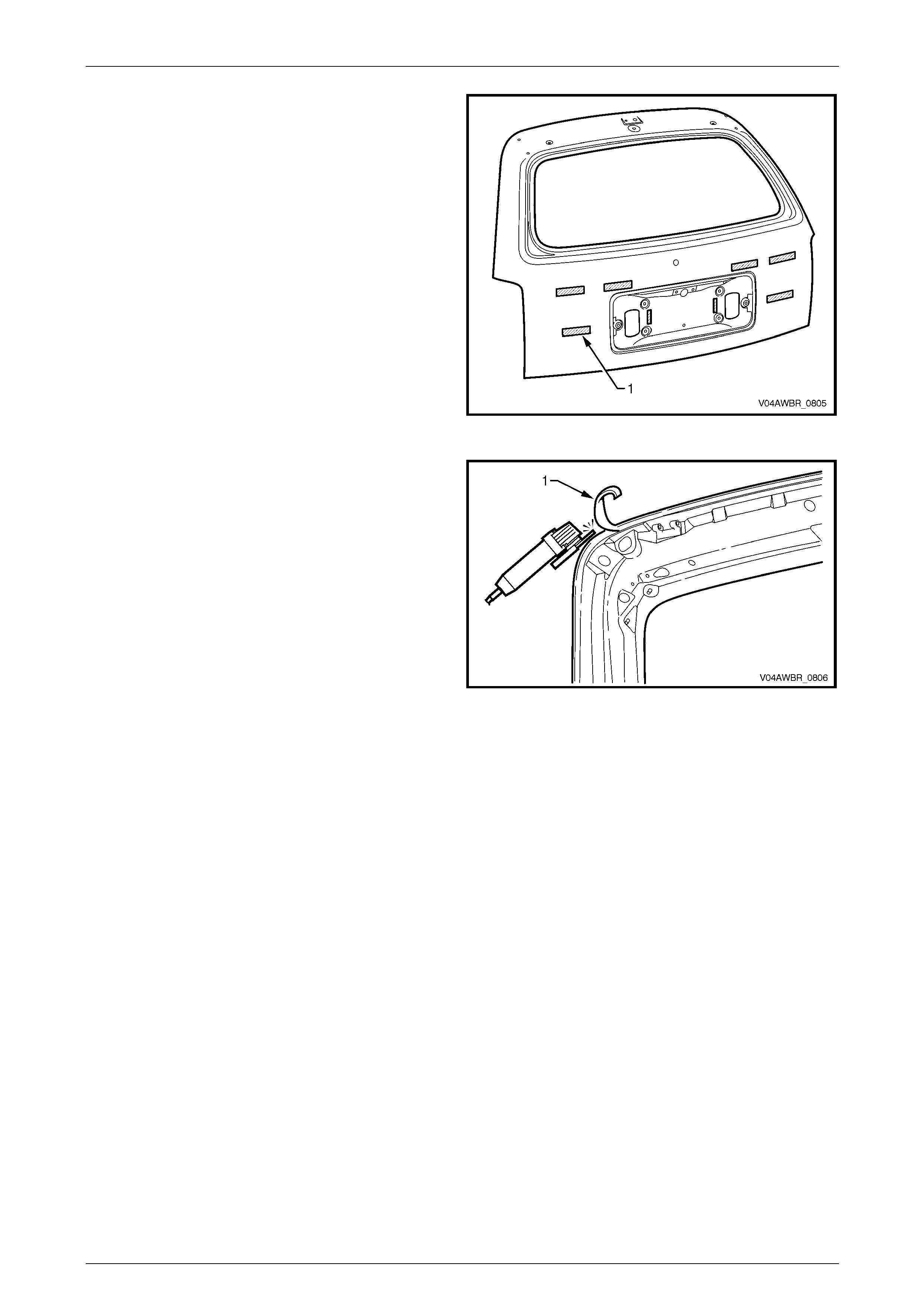
2 Spot cut the welds around the windo w flange attaching
the liftgate outer panel to the inner panel assembly.
Figure 8 – 38
3 Grind or sand the hem from around the edges of the
liftgate.
Figure 8 – 39
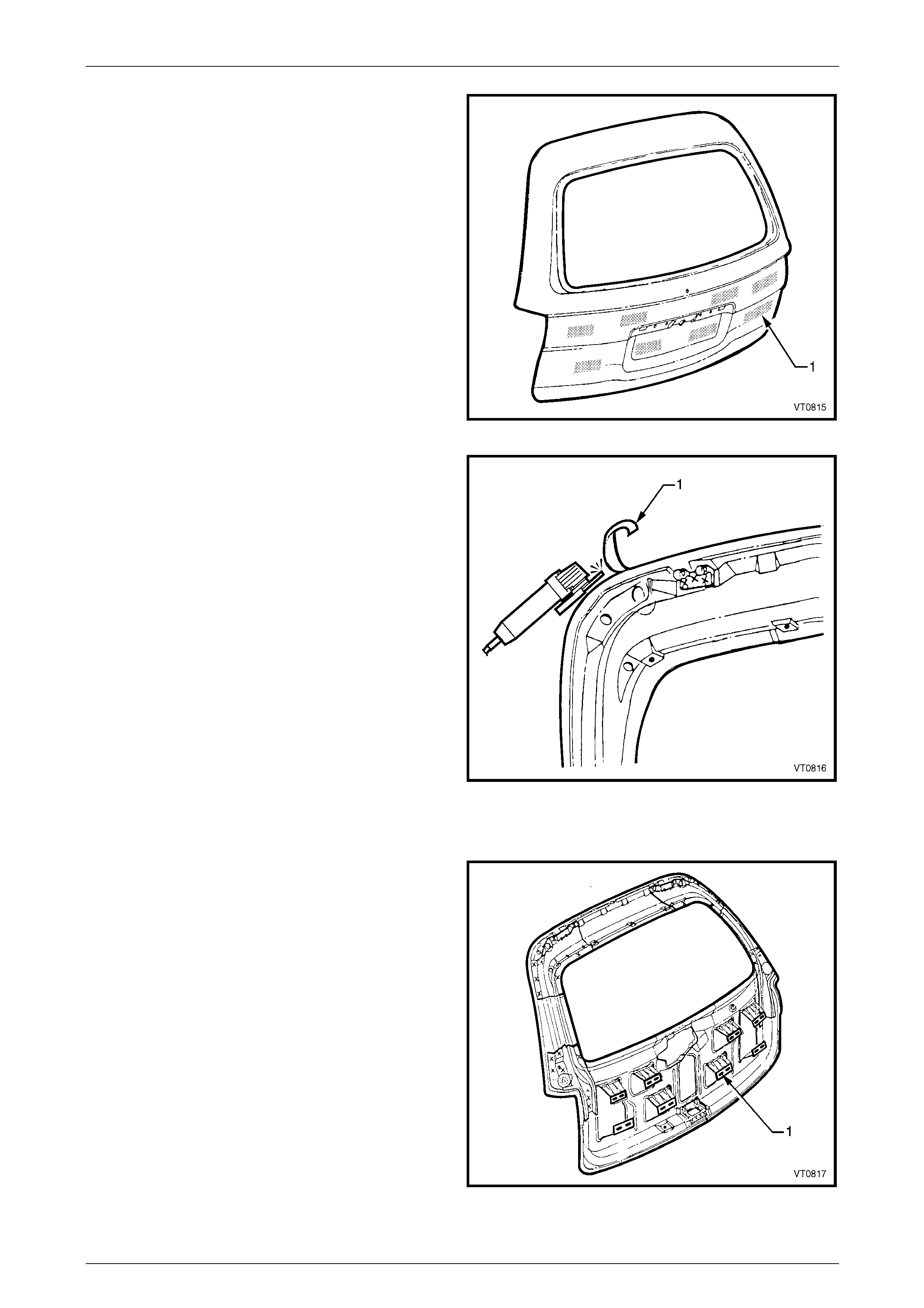
8 Doors, Liftgate and Endgate Page 8-24
Page 8-24
4 Soften the adhesive bet ween the outer panel and the
inner panel support brackets by heating the areas
shaded (1) with a heat gun.
5 Separate the outer panel from the liftgate inner.
Figure 8 – 40
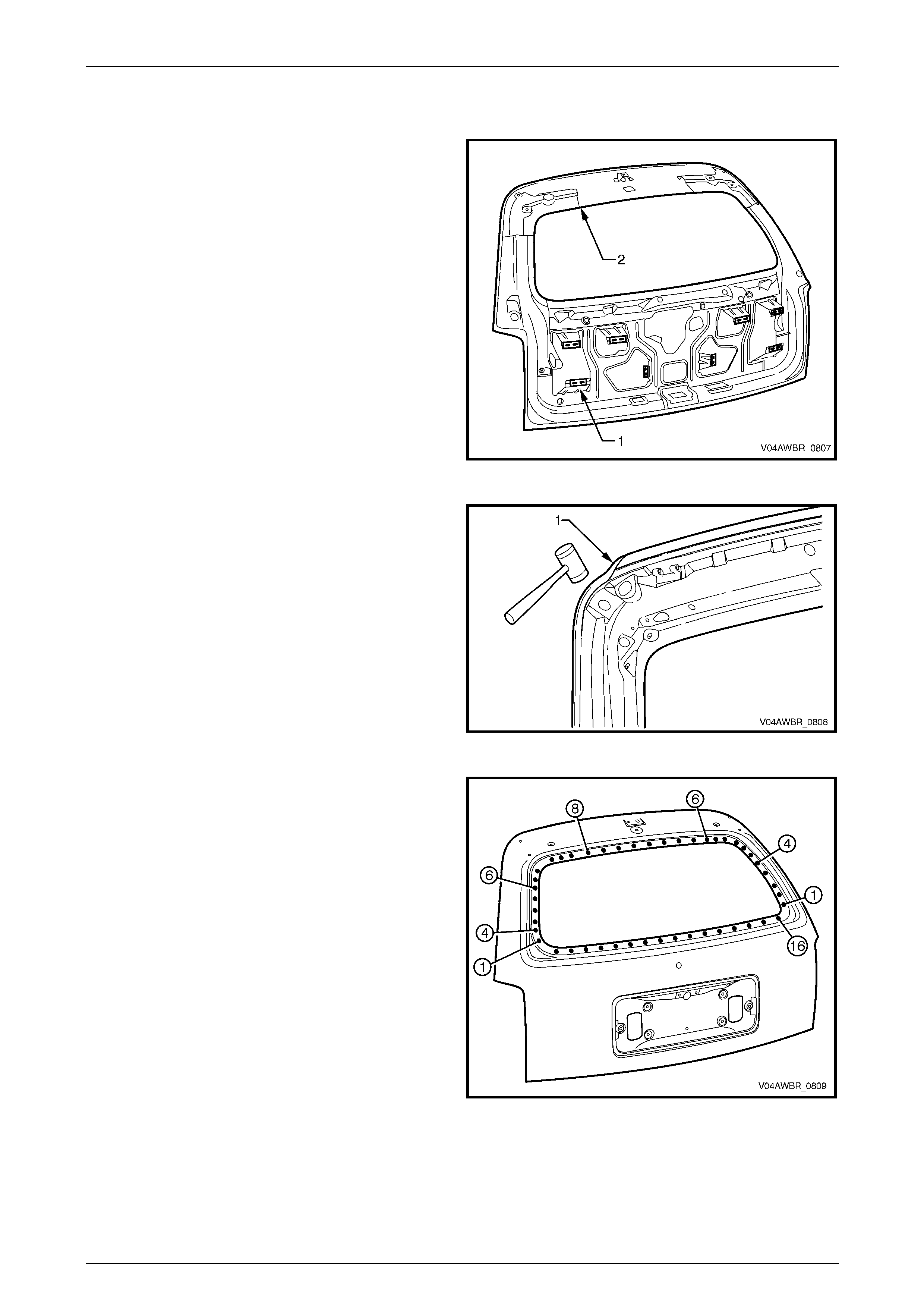
6 Remove the hemming strip from the liftgate inner
panel by chiselling or grinding away the metal strip (1)
and the adhesive.
7 Repair any damage to the liftgate inner panel
assembly.
8 Clean away sealer from the attachin g faces around the
hemming area and clean all remaini ng adhesive from
the outer panel support brackets on the liftgat e inner
panel.
9 Prepare and prime any bare metal as required.
Figure 8 – 41
Replace
1 Apply beads (1) of Anti-flutter Adhesive (Item 5) in 16
places, each 40 mm long, to the support brackets,
refer to Section 3B Body Construction – Wagon.
Figure 8 – 42
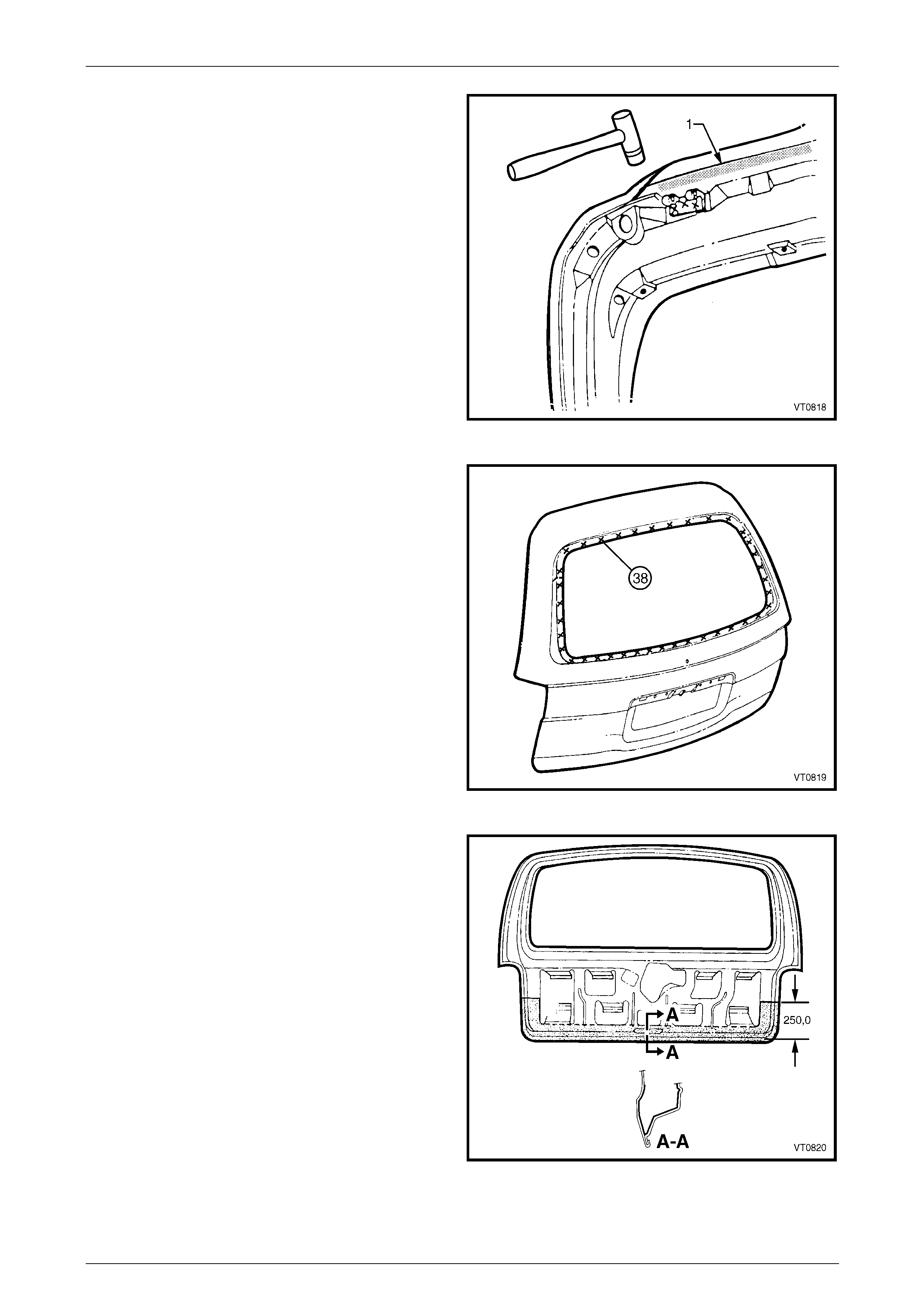
8 Doors, Liftgate and Endgate Page 8-25
Page 8-25
2 Apply structural adhesive (Item 6) to
the mating surfaces of the hem (1), refer to
Section 3B Body Construction – Wagon.
3 Clamp the outer panel in position and fold over the
hem to attach the outer panel firmly to the inner panel
assembly.
NOTE
This procedure must be performed carefully to
avoid damaging the panel surface. The use of
body filler around the outer edges of the outer
panel to rectify hammering damage is
considered unacceptable.
Figure 8 – 43
4 Spot weld the liftgate outer panel to the inner panel
assembly around the window flange.
5 Refinish and paint the liftgate as required.
Refer to Section 3 Body Construction.
6 Apply Joint Sealer (Item 3) as required.
Refer to Section 3B Body Construction – Wagon.
Figure 8 – 44
7 Apply Cavity Wax (Item 8) as required to the inside of
any box sections or areas inaccessible to paint,
refer to Section 3B Body Construction – Wagon.
8 Install the liftgate assembly, refer to
2.6 Liftgate Assembly – Replace.
9 Install the liftgate window, refer to
Section 1A6 Stationary Windows in the MY 2 005 VZ
Service Information.
10 Install the remaining compon ents as required, refer to
Section 1A4 Hood, Rear Compartment Lid, Liftgate
and Endgate in the MY 2005 VZ Service Information.
Figure 8 – 45
8 Doors, Liftgate and Endgate Page 8-26
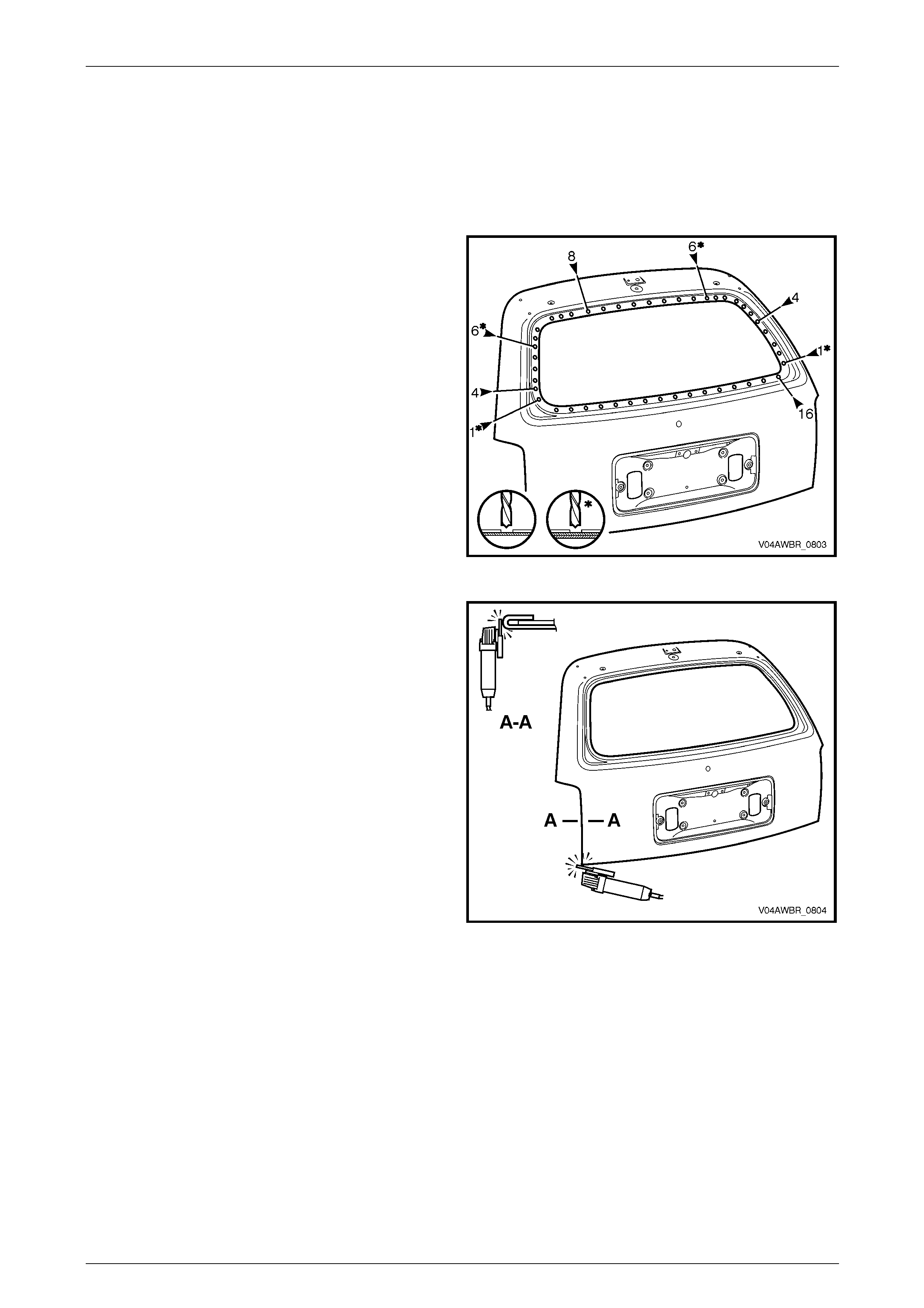
Page 8-26
2.8 Liftgate Outer Panel, AWD Wagon –
Replace
Remove
1 Remove the liftgate from the vehicle, refer to Section 1A4 Hood, Re ar Compartment Lid, Liftgate and Endgate in
the MY 2005 VZ Service Information.
2 Spot cut the welds around the windo w flange attaching
the liftgate outer panel to the inner panel assembly.
Figure 8 – 46
3 Grind or sand the hem from around the outer edge of
the liftgate.
Figure 8 – 47
8 Doors, Liftgate and Endgate Page 8-27
Page 8-27
4 Soften the adhesive bet ween the outer panel and the
inner panel support brackets by heating the areas
shaded (1) with a heat gun.
5 Separate the outer panel from the liftgate inner and
remove.
Figure 8 – 48
6 Remove the remaining hemming strip from the liftgate
inner panel by chiselli ng or grinding away the metal
strip (1) and the adhesive.
7 Repair any damage to the liftgate inner panel
assembly as required.
8 Clean away sealer from the attachin g faces around the
hemming area and clean all remaini ng adhesive from
the outer panel support brackets on the liftgat e inner
panel.
9 Prepare and prime any bare metal as required.
Figure 8 – 49
8 Doors, Liftgate and Endgate Page 8-28
Page 8-28
Replace
1 Apply:
• A 40 mm long bead (1) of Anti-flutter Adhesive
(Item 5) to the support brackets in eight places,
• acrylic spot weld sealer (Item 2) to the window
opening mating surfaces (2), and
refer to Section 3G Body Construction – AWD Wagon.
Figure 8 – 50
2 Apply structural adhesive (Item 6) to
the mating surfaces of the hem (1), refer to
Section 3G Body Construction – AWD Wagon.
3 Clamp the outer panel in position and fold over the
hem to attach the outer panel firmly to the inner panel
assembly.
NOTE
This procedure must be performed carefully to
avoid damaging the panel surface. The use of
body filler around the outer edges of the outer
panel to rectify hammering damage is
considered unacceptable.
Figure 8 – 51
3 Spot weld the liftgate outer panel to the inner panel
assembly around the window flange.
4 Refinish and paint the liftgate as required. R efer to
Section 3G Body Construction – AWD Wagon.
5 Apply Joint Sealer (Item 3) as required. Refer to
Section 3G Body Construction – AWD Wagon.
6 Apply Cavity Wax (Item 8) as r equired to
the inside of the liftgate, any box sections
or areas inaccessible to paint, refer to
Section 3G Body Construction – AWD Wagon.
7 Install the liftgate assembly and other components as
required, refer to Section 1A4 Hood, Rear
Compartment Lid, Liftgate and Endgate in the MY
2005 VZ Service Information.
Figure 8 – 52

8 Doors, Liftgate and Endgate Page 8-29
Page 8-29
2.9 Endgate Assembly – Replace
NOTE
If only the endgate is damaged, it is best to
remove the endgate from the hinges, leaving the
hinges attached to the vehicle. This will avoid
disturbing the joint sealer surrounding the hinges.
Remove
1 Disassemble the endgate hardware as required.
Refer to Section 1A4 Hood, Rear Compartment Lid, Liftgate and Endgate in the MY 2005 VZ Service Information.
2 Mark the position of the endgate screws with a marker
pen as required.
3 With an assistant supporting the endgate, remove the
four screws (1) and washers attaching the endgate
assembly to the hinge assemblies.
4 Remove the endgate assembl y by sliding it rearwards
from the hinge assemblies.
Figure 8 – 53
Reinstall
Installation is the reverse of removal noting the following:
1 Align the endgate screws with the pen marks or adjust the endgate refer to Adjust in this Section.
2 Tighten the screws to the specified torque.
Endgate Assembly Attaching Screw
Torque Specification ...............................15.0 – 25.0 Nm
3 Install the endgate hook label to the left-hand side of
the endgate inner panel as shown.
Figure 8 – 54

8 Doors, Liftgate and Endgate Page 8-30
Page 8-30
Adjust
Correct alignment of the endgate assembl y is critical to its operation and to the aesthetics of the vehicle . The following
components allow adjustment of the endgate:
• Endgate hinge assembl y scre ws (end gate and body side): Provide vertical, horizo ntal and skew adjustment.
• Endgate striker latch: Provides adjustment flushness of the end gate assembly to the vehicle.
Whenever alignment is required, perform adjustment in the following order.
1 Remove the endgate striker.
2 Ensure the endgate weatherstrip assembly is installed.
3 Carefully close the end gate, watching each side does not contact the vehicle.
4 Check the alignment of the endgate for height, flushness, width and consistency of gap to the side panel outer and
tail lamps, refer to Section 3 Body Construction for specifications.
5 As required, loosen the hinge assembly attaching screws and reposition the endgate. If enough adjustment cannot
be obtained, loosen the lower hinge assembly screws.
6 Temporarily tighten the screws.
7 Install the endgate striker, refer to Section 1A4 Hood, Rear Compartment Lid, Liftgate and Endgate in the MY 2005
VZ Service Information.
8 Close the endgate and adj ust the position of the striker to provide flushnes s of the endgate to the side panel outer
and tail lamps.
9 Check that all screws are tightened to their specified torq ue.
Endgate Assembly Upper Attaching
Screw Torque Specification ....................15.0 – 25.0 Nm
Endgate Assembly Lower Attaching
Screw Torque Specification ....................15.0 – 35.0 Nm
8 Doors, Liftgate and Endgate Page 8-31
Page 8-31
2.10 Endgate Outer Panel – Replace
Remove
1 Remove the endgate assembl y from the vehicle as described in 2.9 Endgate Assembly – Replace.
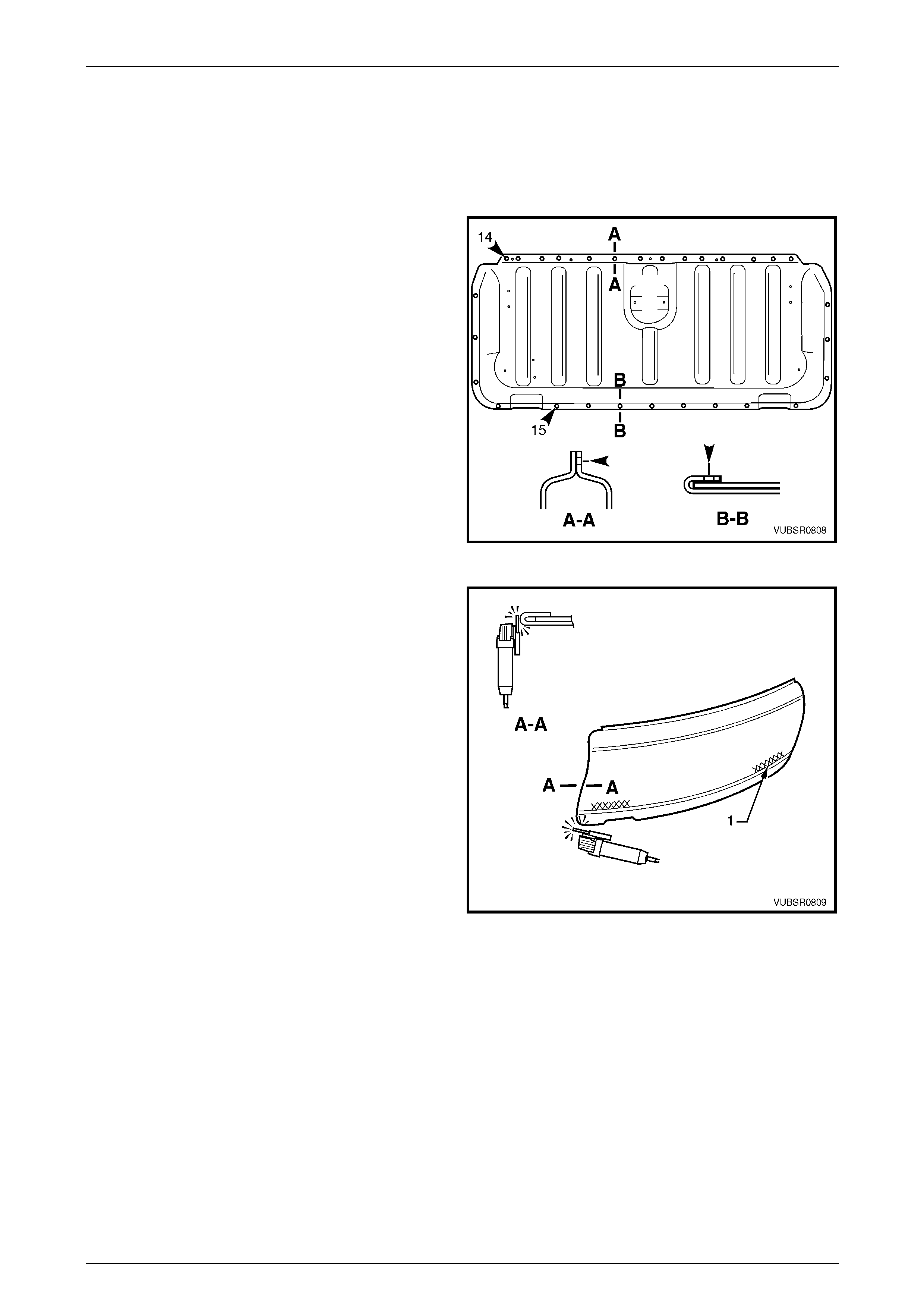
2 From the outer side, spot cut the 14 welds attaching
the upper edge of the endgate outer panel to the inner
panel assembly.
NOTE
Cut through the outer panel only, refer to
Section A-A.
3 From the inner side, spot cut the 15 welds attaching
the endgate outer panel hem to the inner panel
assembly.
NOTE
Cut through the outer panel only, refer to
Section B-B.
Figure 8 – 55
4 Grind or sand the edge of the hem from around the
edges of the endgate.
5 Soften the adhesive between the outer panel and
hinge reinforcement by heating the areas (1) with a
heat gun.
6 Separate the outer panel from the endgate inner.
Figure 8 – 56
8 Doors, Liftgate and Endgate Page 8-32
Page 8-32
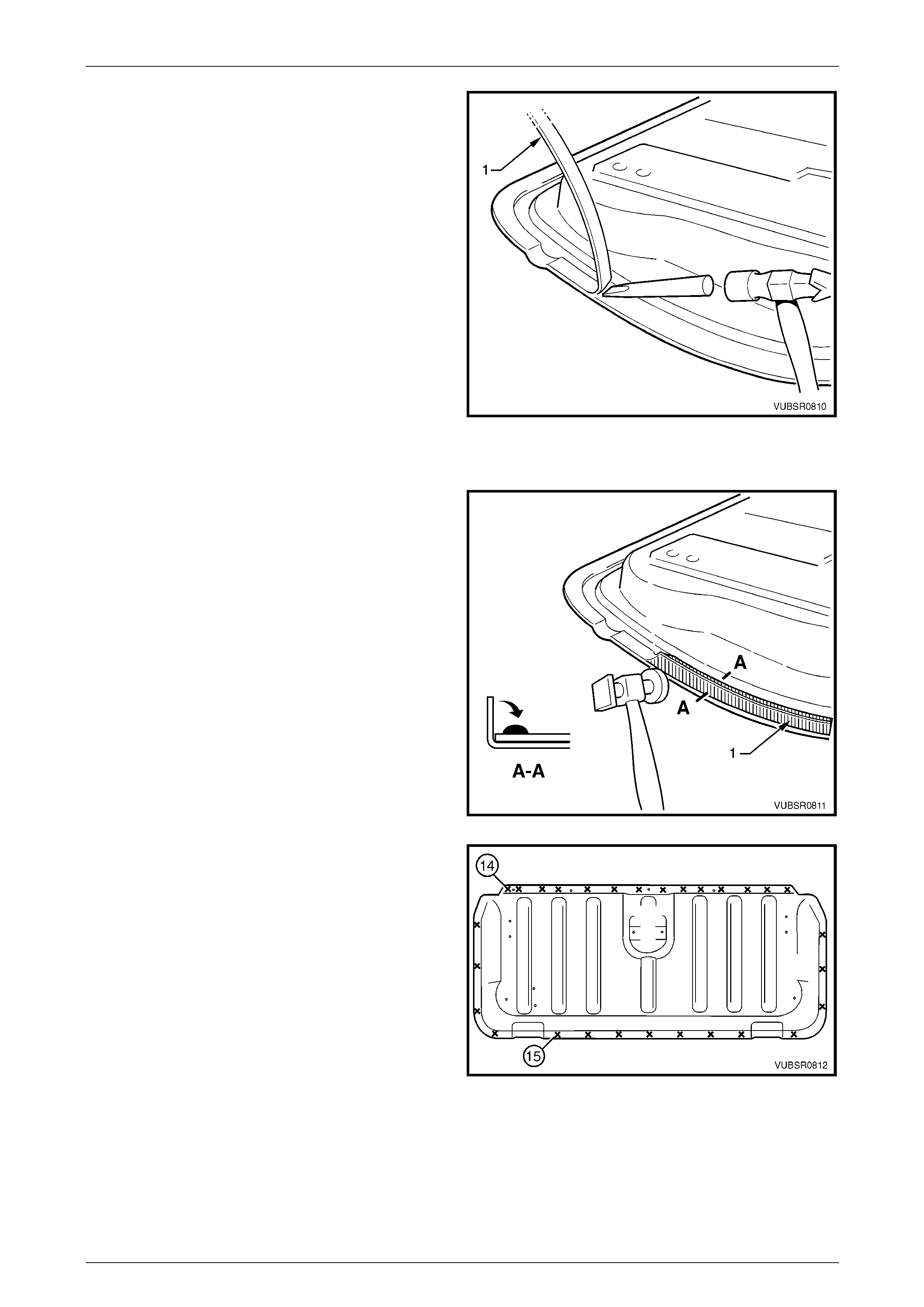
7 Chisel the hemming strip (1) from the endgate inn er
panel.
8 Repair any damage to the endgate inner panel
assembly.
9 Clean away sealer or adhesive from the attachin g
faces around the hemming area and clean all
remaining anti-flutter adhesive from the hinge
reinforcements on the endgate inner panel.
10 Prepare and prime any bare metal as requir ed.
Figure 8 – 57
Replace
1 Apply structural adhesive (Item 6) to
the mating surfaces of the hem (1), refer to
Section 3 Body Construction.
2 Apply anti-flutter adhesive (Item 5) to the
two endgate hinge reinforcements, refer to
Section 3 Body Construction.
3 Clamp the outer panel in position and fold the hem
over to attach the outer panel firmly to the inner panel
assembly. NOTE
This procedure must be performed carefully to
avoid damaging the panel surface. The use of
body filler around the outer edges of the outer
panel to rectify hammering damage is
considered unacceptable.
Figure 8 – 58
4 Spot or plug weld the endgat e outer panel to the inner
panel assembly. NOTE
Place wet rags against the outer panel around
the weld area to minimise heat distortion.
5 Dress the hem and edges of the outer panel as
required.
6 Refinish and paint the endgate as requ ired.
Refer to Section 3 Body Construction.
7 Apply Joint Sealer (Item 3) as required.
Refer to Section 3 Body Construction.
8 Apply Cavity Wax (Item 8) as required to the inside of
any box sections or areas inaccessible to paint,
refer to Section 3 Body Construction.
9 Install the endgate assembly,
refer to 2.9 Endgate Assembly – Replace.
10 Install the endgate hardware as required. Refer to
Section 1A4 Hood, Rear Compartment Lid, Liftgate
and Endgate in the MY 2005 VZ Service Information.
Figure 8 – 59

8 Doors, Liftgate and Endgate Page 8-33
Page 8-33
3 Torque Wrench Specifications
Check assembly to pillar retaining screw.......................................5.0 – 7.0 Nm
Check assembly to door retaining nuts......................................13.0 – 15.0 Nm
Liftgate hinge (body side)attaching screw .................................13.0 – 25.0 Nm
Endgate assembly attaching screw...........................................15.0 – 25.0 Nm
Endgate assembly upper attaching ...........................................15.0 – 25.0 Nm
Endgate assembly lower attaching screw .................................15.0 – 35.0 Nm
8 Doors, Liftgate and Endgate Page 8-34
Page 8-34
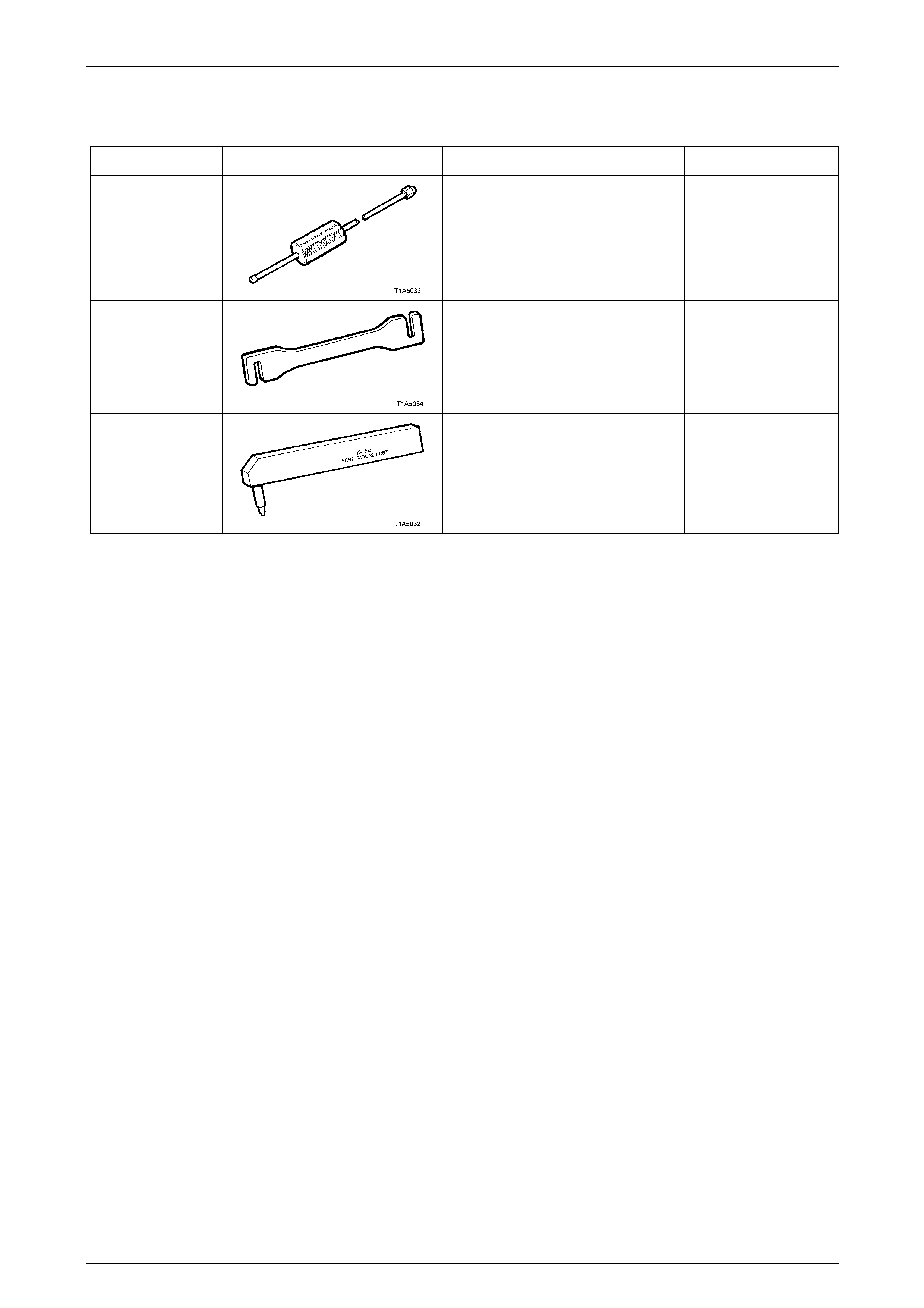
4 Special Tools
Tool Number Illustration Description Tool Classification
AU170
Door Hinge Pin Removal Tool
Used for removing door hinge pivot
sleeves
Available
AU184
Door Hinge Setting Tool
Used to adjust door alignment Desirable
AU303
Door Hinge Sleeve Installer
Used to install door hinge piv ot
sleeves
Available