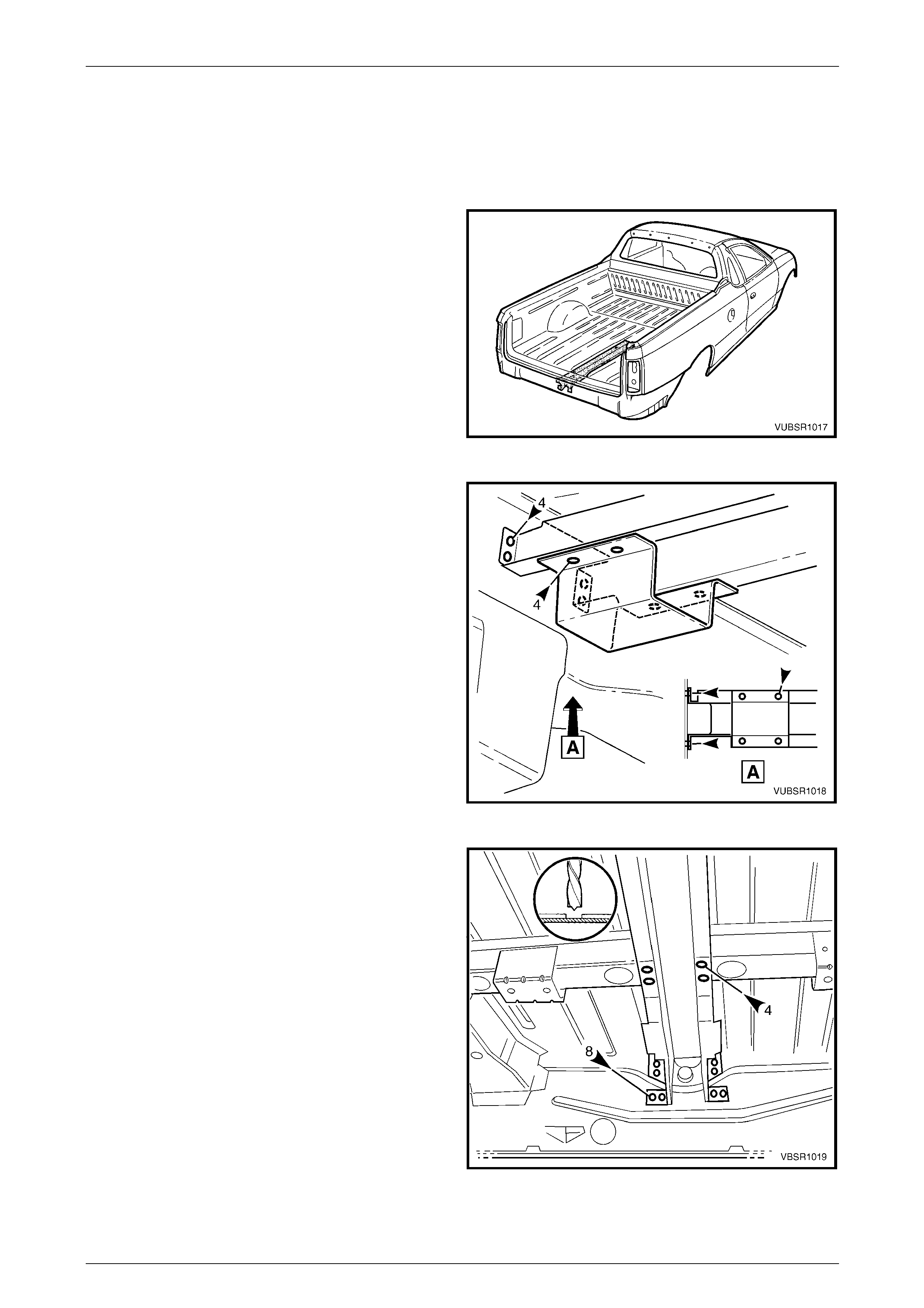
10C Body Rear – Utility Page 10C-1
Page 10C-1
Section 10C
Body Rear – Utility
ATTENTION
Before performing any service operation or other procedure described in this Section, refer to Section 2
Precautions in this Supplement and Section 00 Warnings, Cautions and Notes in the MY2005 VZ Service
Information for correct workshop practices with regard to safety and/or property damage.
The structure of the body shell has been
developed using complex design and
development techniques. In addition to
meeting all required standards, the vehicle
body is also a critical part of the overall safety
systems. It is therefore imperative the repair
procedures described here are adhered to
during all vehicle body repairs.
1 General Description ...............................................................................................................................2
1.1 Body Rear Components........................................................................................................................................ 2
2 Service Operations.................................................................................................................................4
2.1 Rear End Lower Panel – Replace ......................................................................................................................... 4
Remove................................................................................................................................................................... 4
Replace................................................................................................................................................................... 5
2.2 Endgate Hinge Bracket Assembly – Replace...................................................................................................... 7
Remove................................................................................................................................................................... 7
Replace................................................................................................................................................................... 8
2.3 Rear End Panel – Replace..................................................................................................................................... 9
Remove................................................................................................................................................................... 9
Replace................................................................................................................................................................. 11
2.4 Load Floor Centre Rail Assembly – Replace..................................................................................................... 13
Remove................................................................................................................................................................. 13
Replace................................................................................................................................................................. 14
2.5 Load Floor Reinforcement Rail Assembly – Replace ....................................................................................... 16
Remove................................................................................................................................................................. 16
Replace................................................................................................................................................................. 17
2.6 Crossmember Assembly No. 2 – Replace ......................................................................................................... 20
Remove................................................................................................................................................................. 20
Replace................................................................................................................................................................. 21
2.7 Rear Floor Panel Outer Extension – Replace.................................................................................................... 22
Remove................................................................................................................................................................. 22
Replace................................................................................................................................................................. 22
2.8 Rear Tie Down Assembly – Replace .................................................................................................................. 23
Remove................................................................................................................................................................. 23
Replace................................................................................................................................................................. 23
2.9 Rear Side Rail Assembly – Replace................................................................................................................... 24
Remove................................................................................................................................................................. 24
Replace................................................................................................................................................................. 26
2.10 Load Floor Panel Assembly – Replace .............................................................................................................. 29
Remove................................................................................................................................................................. 29
Replace................................................................................................................................................................. 32
2.11 Rear Floor Panel – Replace................................................................................................................................. 35
Remove................................................................................................................................................................. 35
Replace................................................................................................................................................................. 37
10C Body Rear – Utility Page 10C-2
Page 10C-2
1 General Description
This Section describes replac ement procedures for the rear section compo nents of the Uti lity body structure. Removal of
bolt-on and mechanical comp onents is not covered. Reference must be made to the appropriate Sections in the MY
2005 VZ Service Information.
When repairing the rear of the vehicle, care must be taken to ensure the structure is returned to its original production
configuration.
NOTE
It is imperative that the correct body adhesives,
sealers, deadeners and cavity waxes are used
when repairing the body structure. Refer to
Section 3C Bod y Construction – Utility for details
of the correct materials and their commercially
available equivalents.
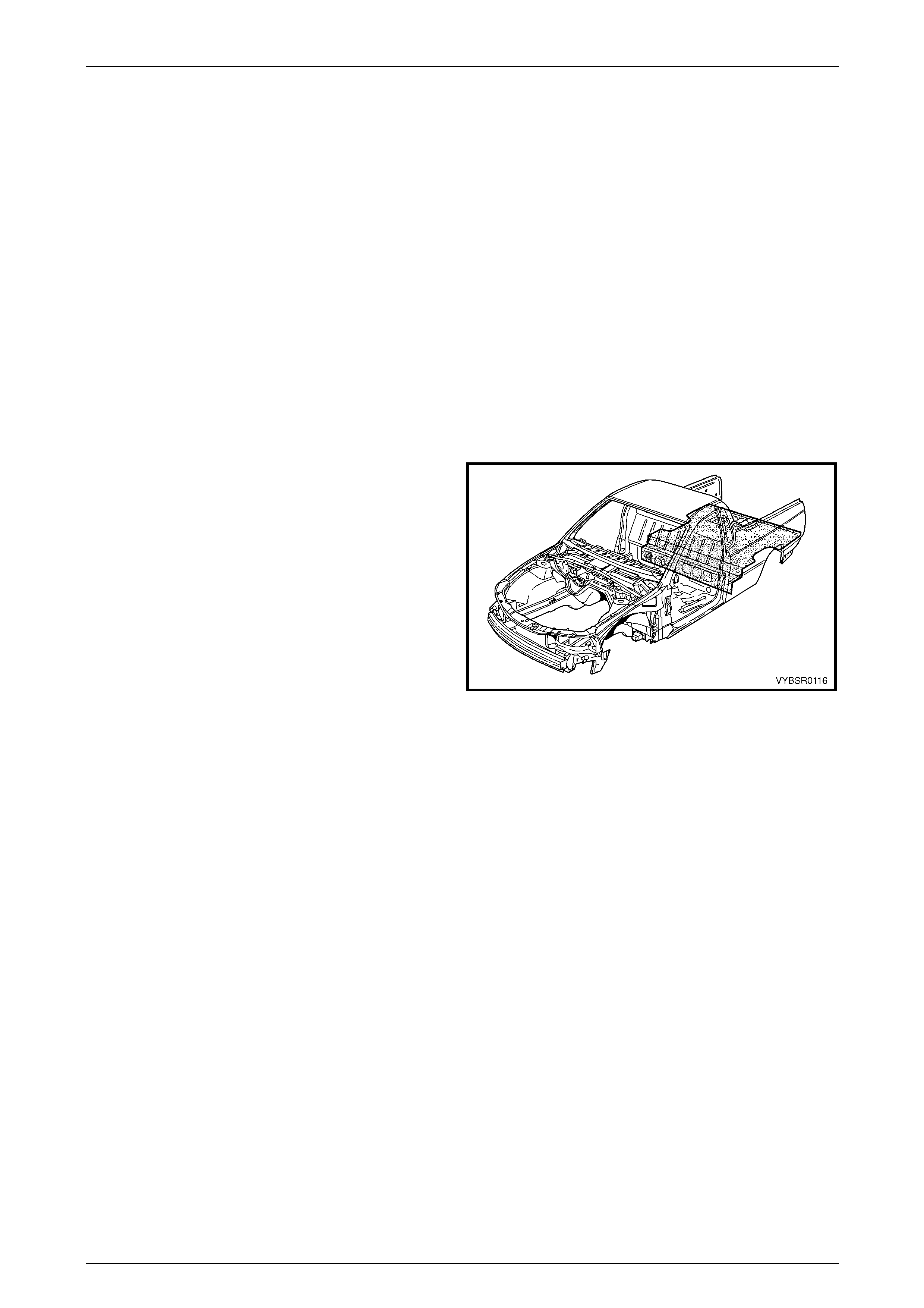
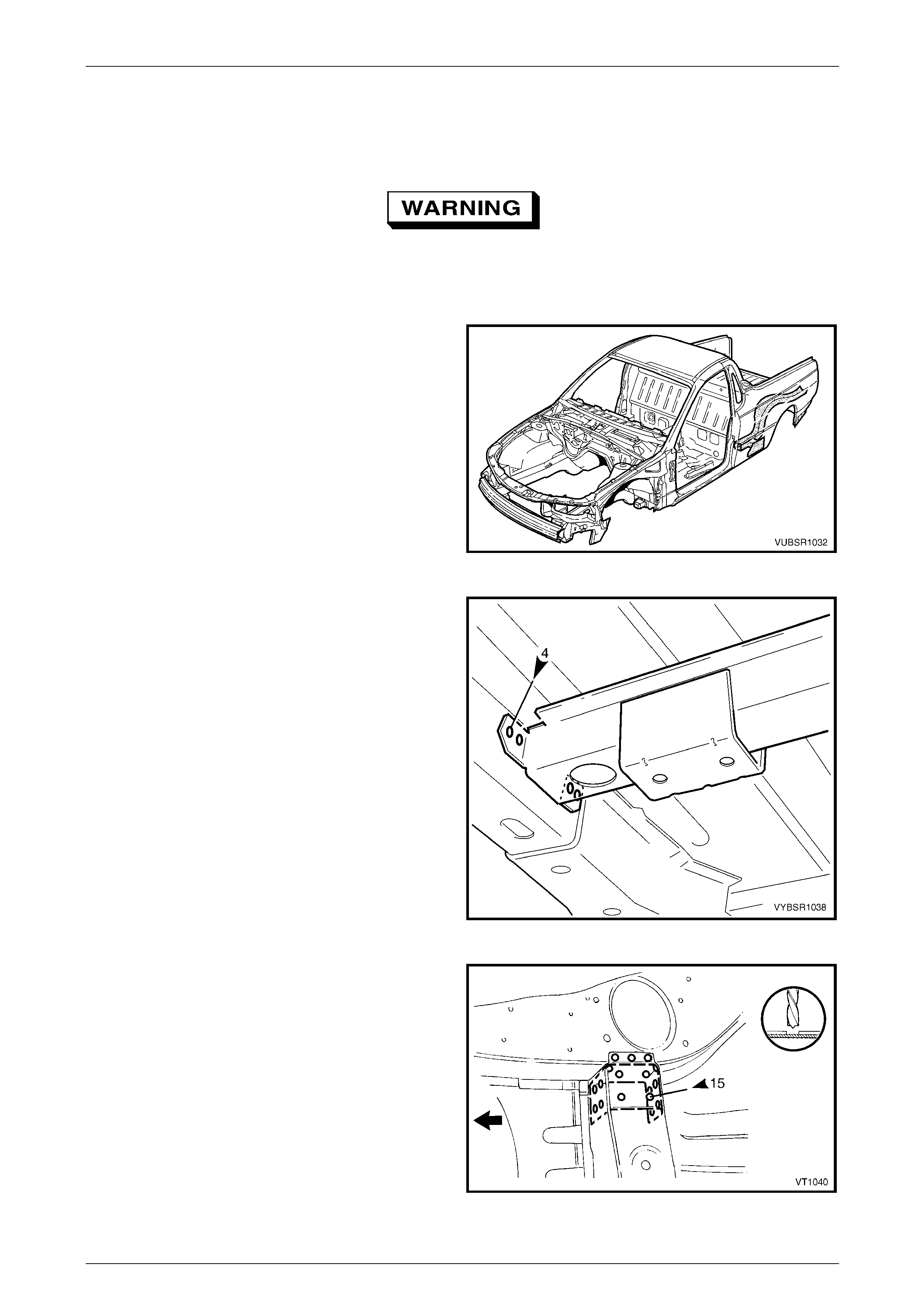
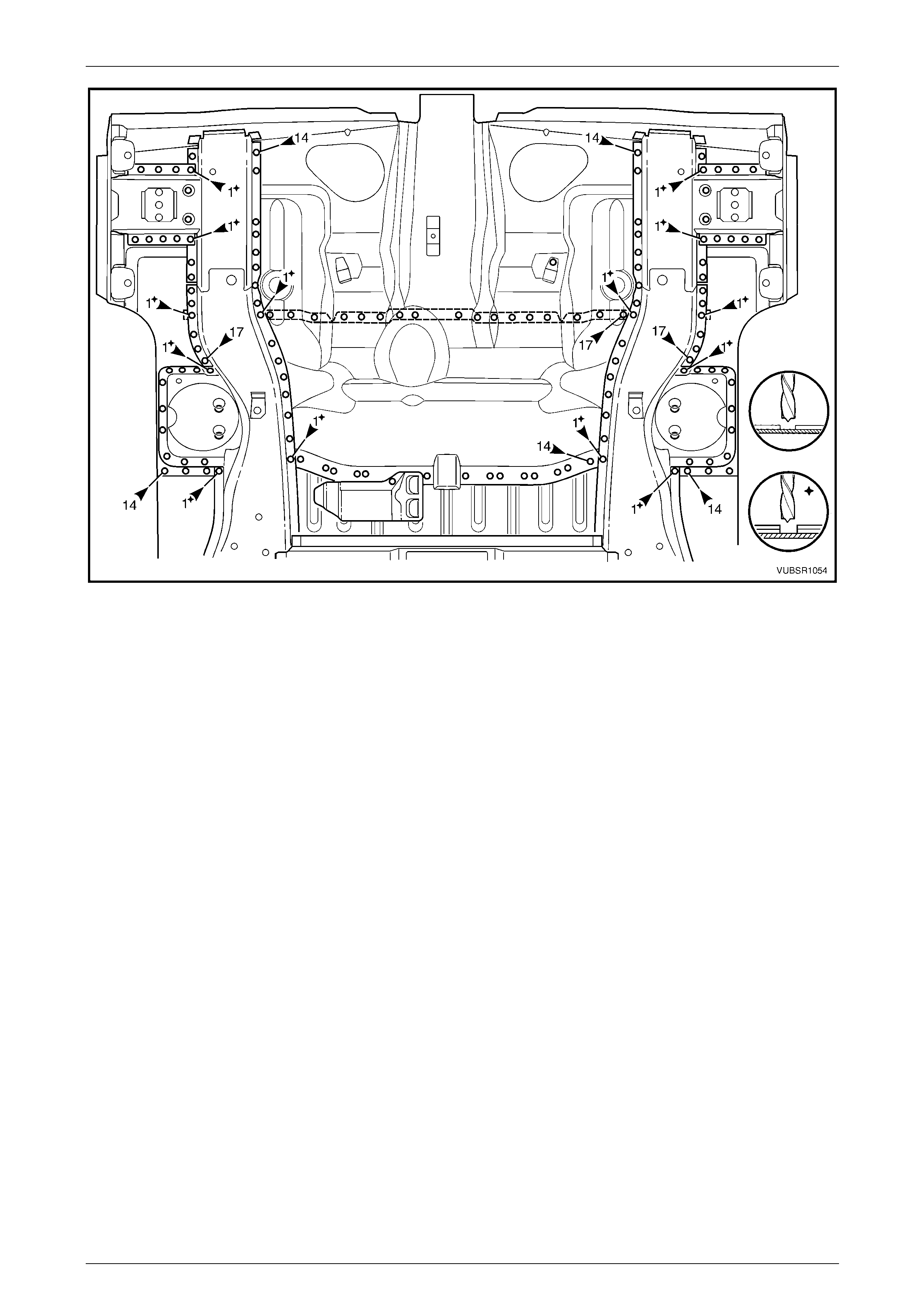
1.1 Body Rear Components
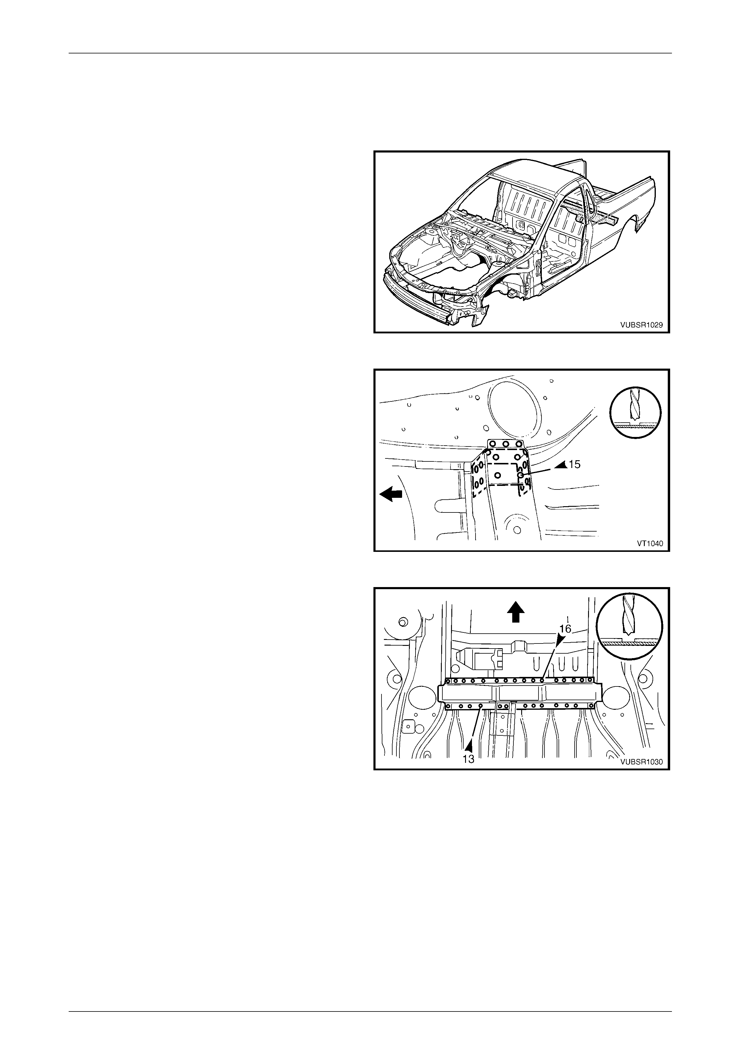
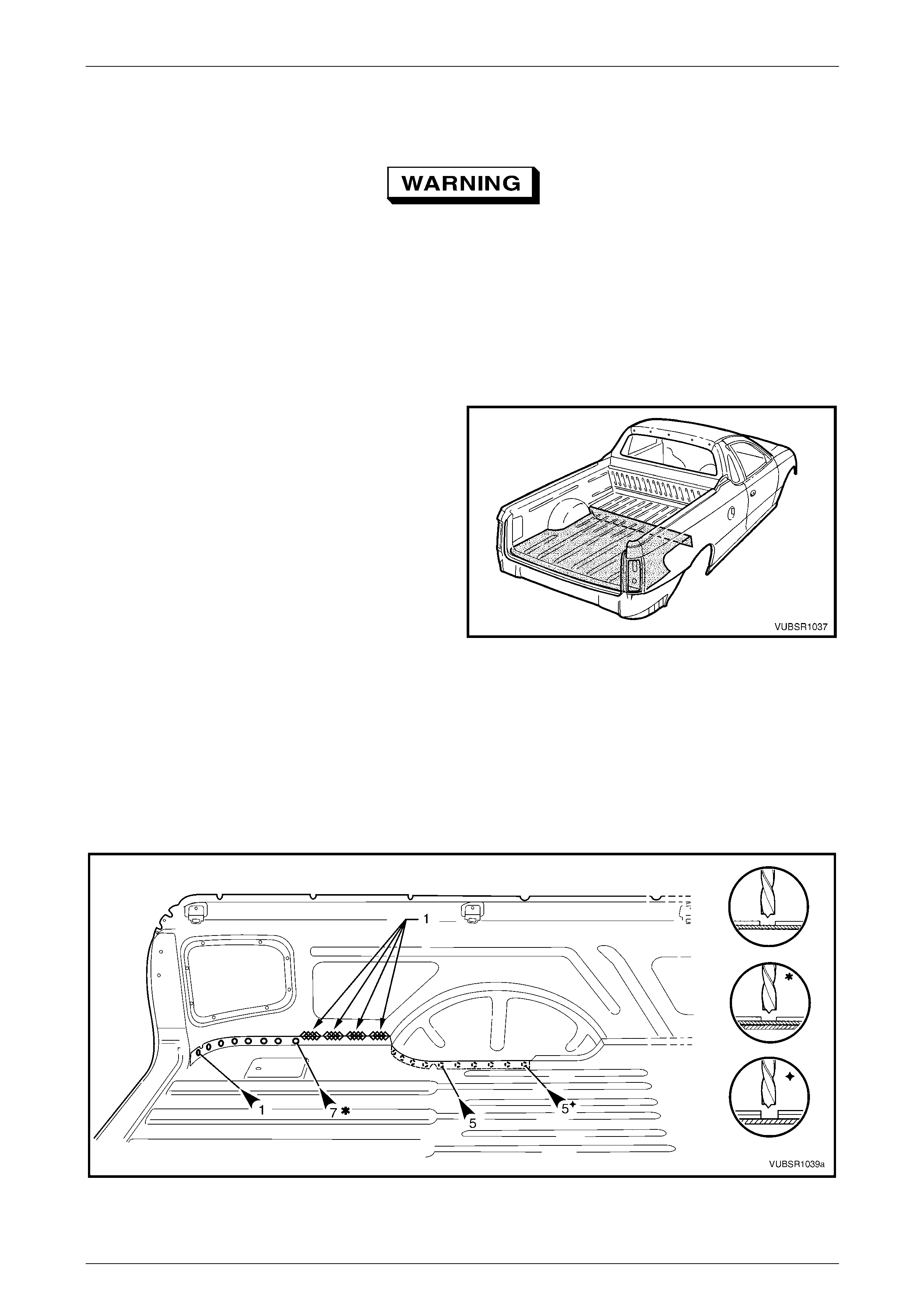
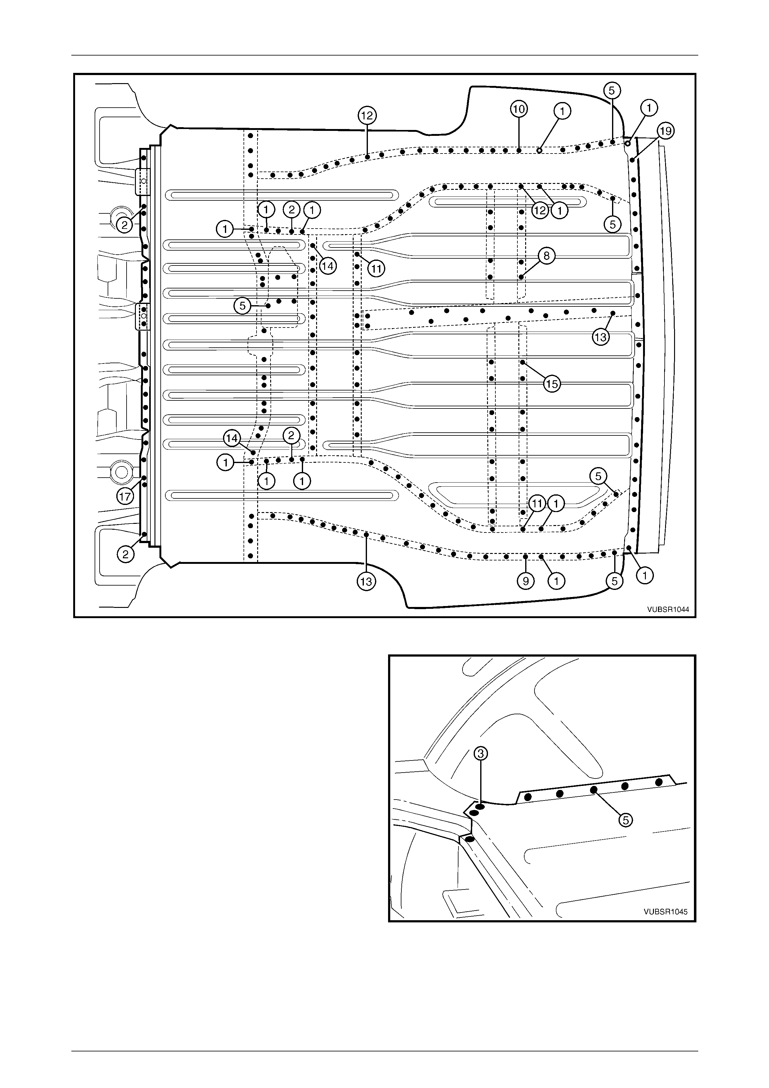
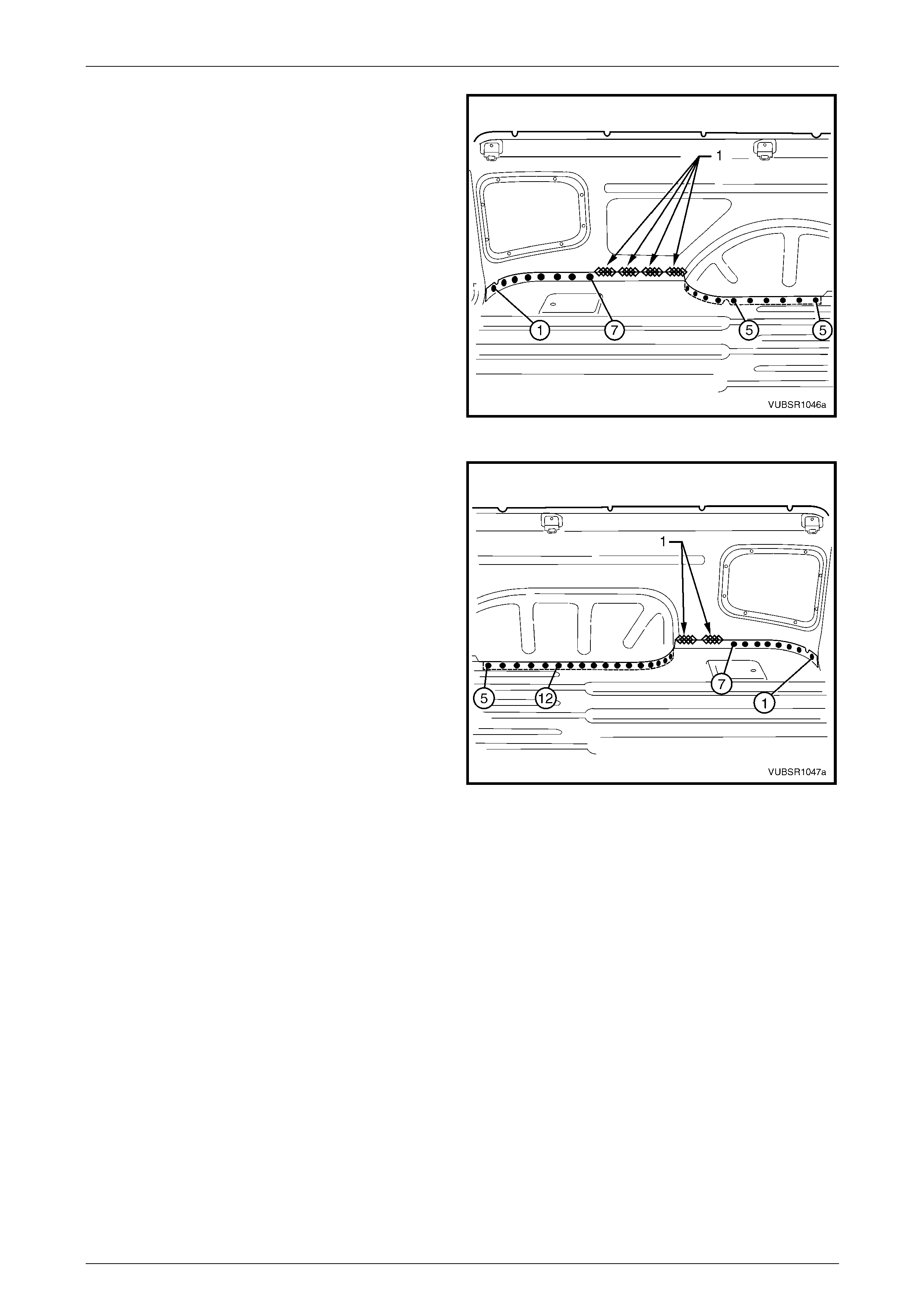
The shaded components in Figure 10C – 1 are those dealt
with in this Section. The components and assemblies shown
in Figure 10C – 2 are the ser v iceable parts that form the
basis of the repair procedures in this Section.
For a detailed view of the body components, refer to
Section 3C Body Construction – Utility.
NOTE
Always refer to an Authorised Retailer for spare
parts availability configurations.
Figure 10C – 1
10C Body Rear – Utility Page 10C-3
Page 10C-3
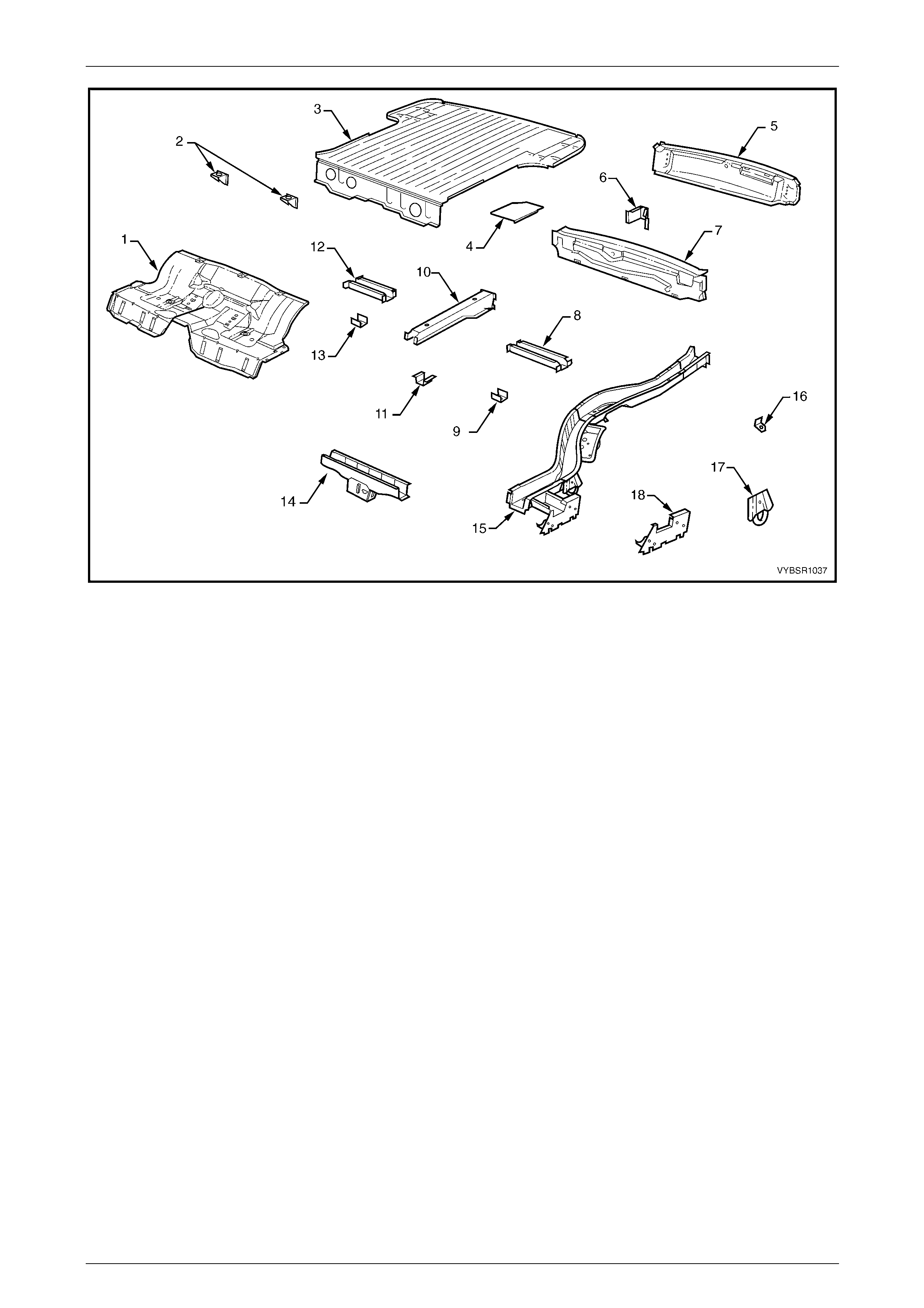
Figure 10C – 2
Legend
1 Rear Floor Panel Assembly
2 Fuel Tank Bracket Assembly
3 Load Floor Panel
4 Load Floor Panel Reinforcement, Left-hand / Right-hand
5 Rear End Lower Panel
6 Endgate Hinge Bracket Assembly, Left-hand / Right-hand
7 Rear End Panel
8 Load Floor Reinforcement Rail, Left-hand
9 Spare Wheel Support, Left-hand
10 Load Floor Centre Rail
11 Spare Wheel Support
12 Load Floor Reinforcement Rail, Right-hand
13 Spare Wheel Support, Right-hand
14 Crossmember Assembly No. 2
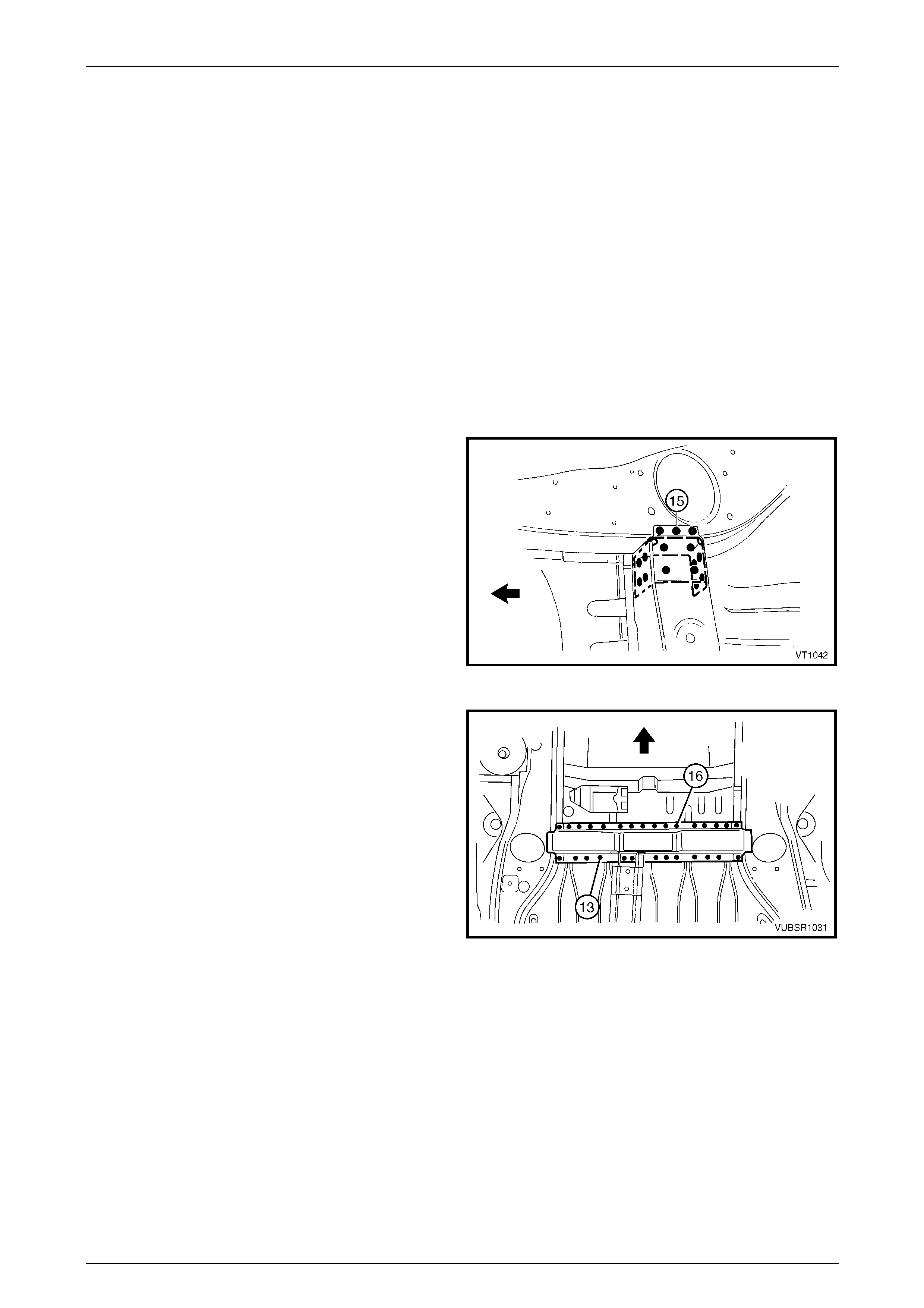
15 Rear Side Rail Assembly, Left-hand / Right-hand
16 Rear Brake Hose Bracket, Left-hand / Right-hand
17 Rear Tie Down Assembly, Left-hand / Right-hand
18 Rear Floor Panel Outer Extension , Left-hand / Right-hand
NOTE
Rear Side Rail Assembly (15) includes parts 16,
17 and 18.
10C Body Rear – Utility Page 10C-4
Page 10C-4
2 Service Operations
2.1 Rear End Lower Panel – Replace
Remove
NOTE
If the rear end panel (inner) is also
to be replaced, remove the rear end
panels as an assembly. Refer to
2.3 Rear End Panel – Replace.
1 Remove the adjacent bolt-on panels and components
as described in the appropriate Section of th e MY
2005 VZ Service Information.
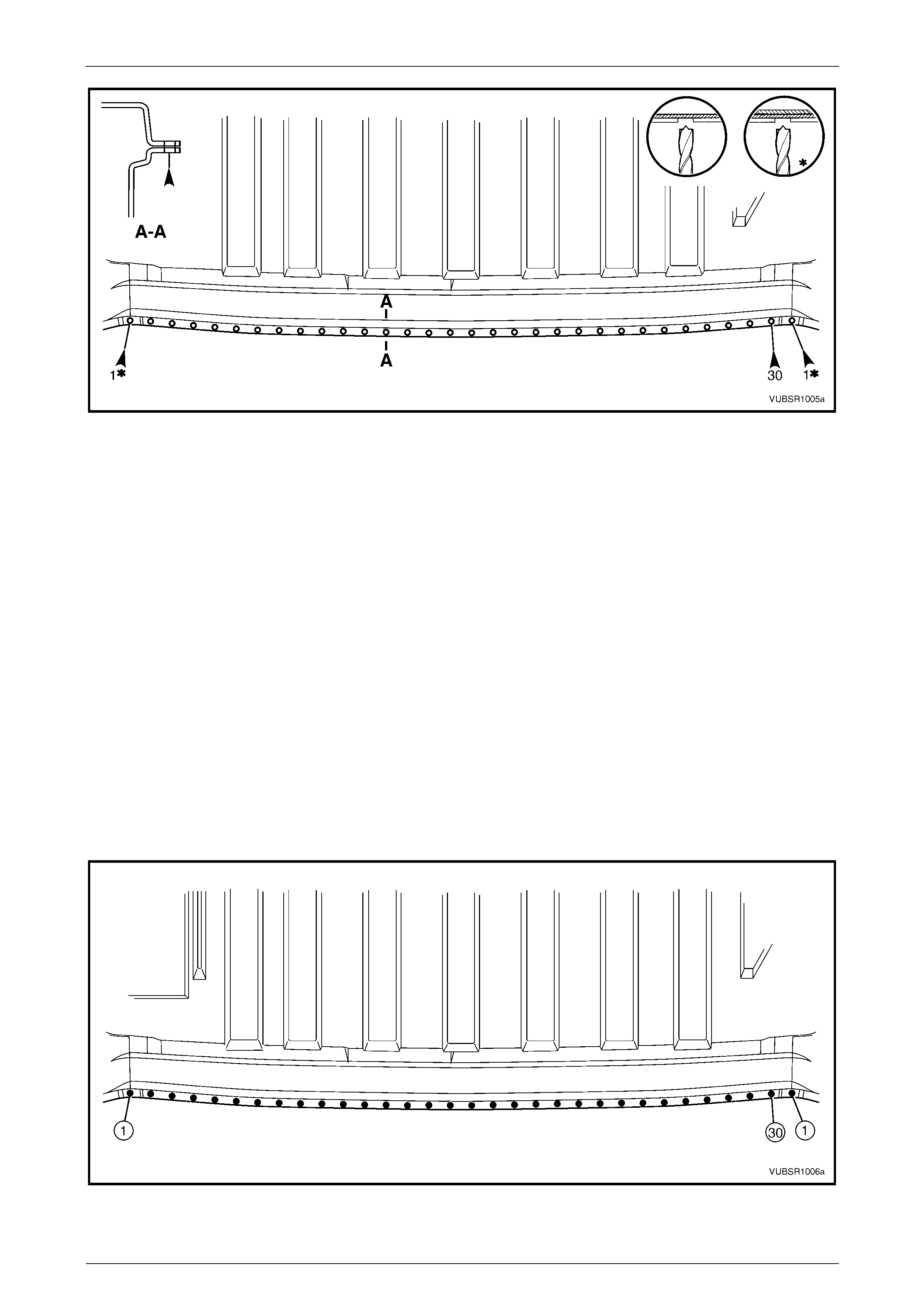
2 Spot cut the welds attaching the rear end lower panel
to the rear end panel and side inner upper panel,
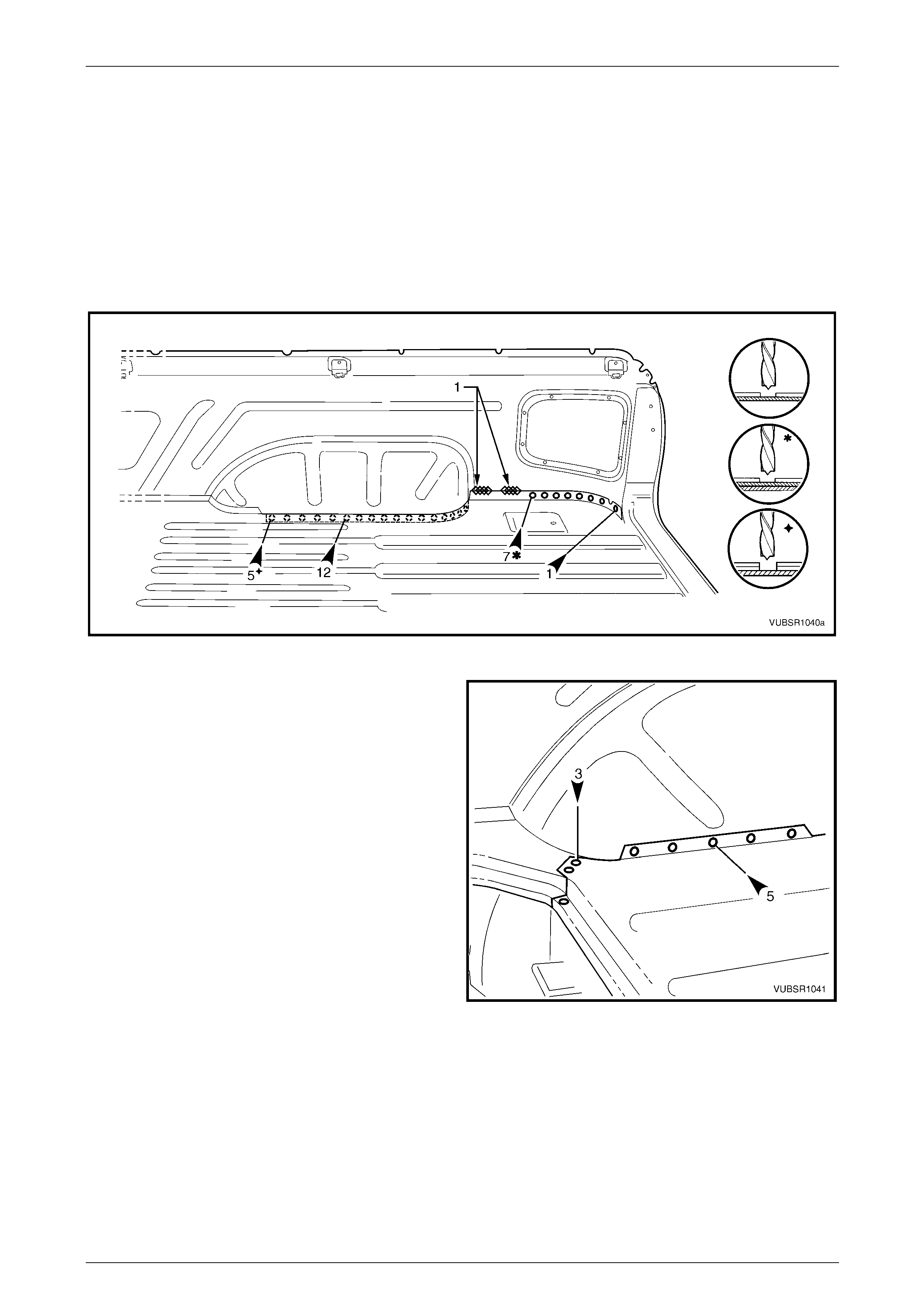
refer to Figure 10C – 4. Figure 10C – 3
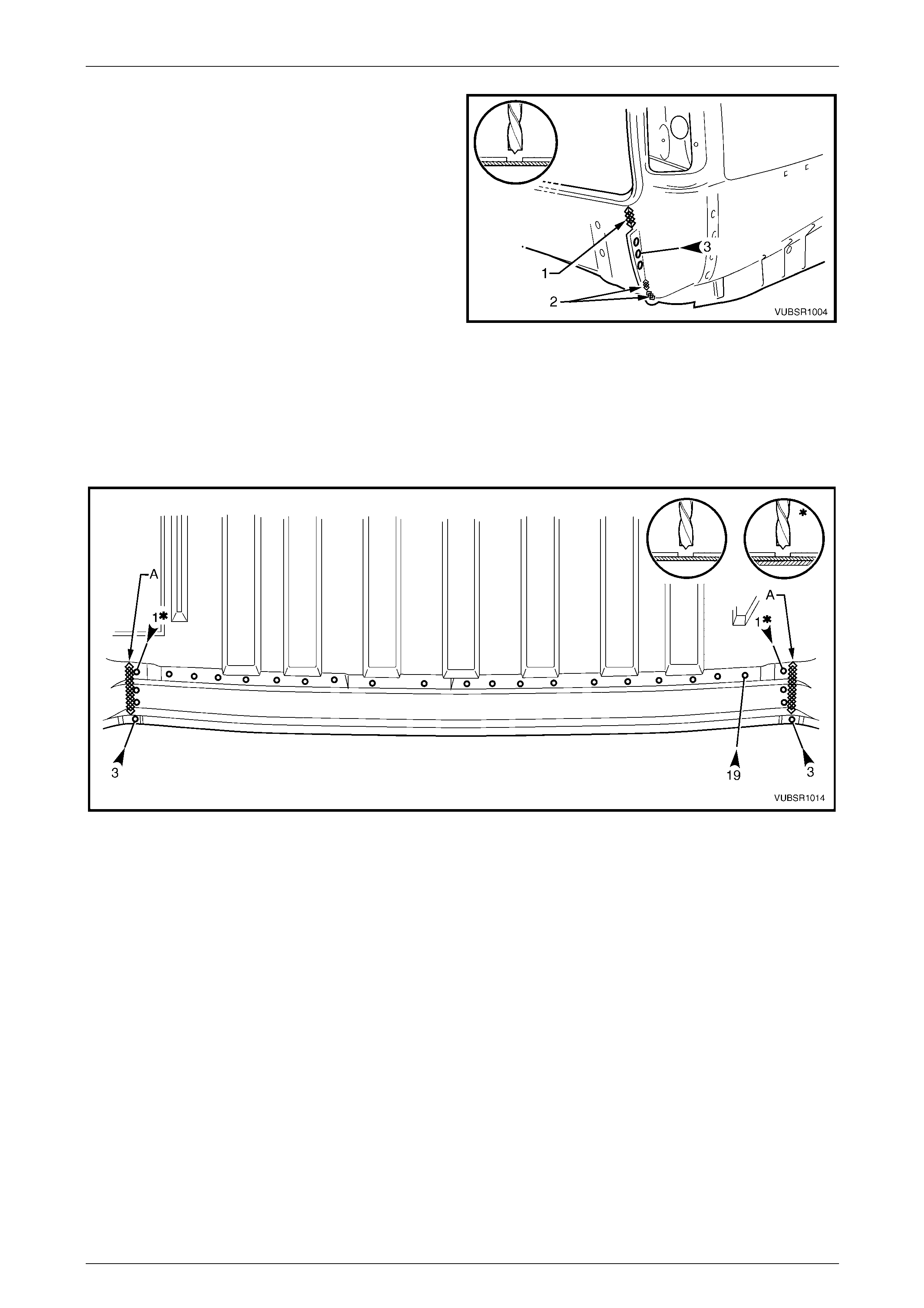
Figure 10C – 4
3 Grind off the three MIG welds (1) and (2) attaching the
rear end lower panel to the quarter panel e xtension.
4 Spot cut the three welds attaching the rear end lower
panel to the quarter panel extension.
5 Spot cut the welds attaching the rear end lower panel
to the rear end panel and quar ter lower rear panel,
refer to Figure 10C – 6.
6 Remove the rear end lo wer panel from the vehicl e and
repair any damage to adjacen t parts as required.
Figure 10C – 5
10C Body Rear – Utility Page 10C-5
Page 10C-5
Figure 10C – 6
Replace
NOTE
• Spot welding is the preferred method for
attaching of panels and should be used
whenever possible. Where the spot welding
equipment available will not access the
required weld position, a plug weld should be
performed.
• The same number and position of spot welds
(or plug welds) should be used when
replacing the panel, as was used during
manufacture, in order to maintain the original
structural strength of the vehicle.
1 As required, mark the new panel with drilling locations in preparation for plug welding. Drill holes as req uired.
2 Prepare all mating surfaces and treat with Weld Through Primer (Item 1) as requir ed,
refer to Section 3C Body Construction – Utility.
3 Clamp the rear end lower panel in p ositio n on the vehicle and spot or plug weld to the rear end p anel and quarter
lower rear panel, refer to Figure 10C – 7.
Figure 10C – 7

10C Body Rear – Utility Page 10C-6
Page 10C-6
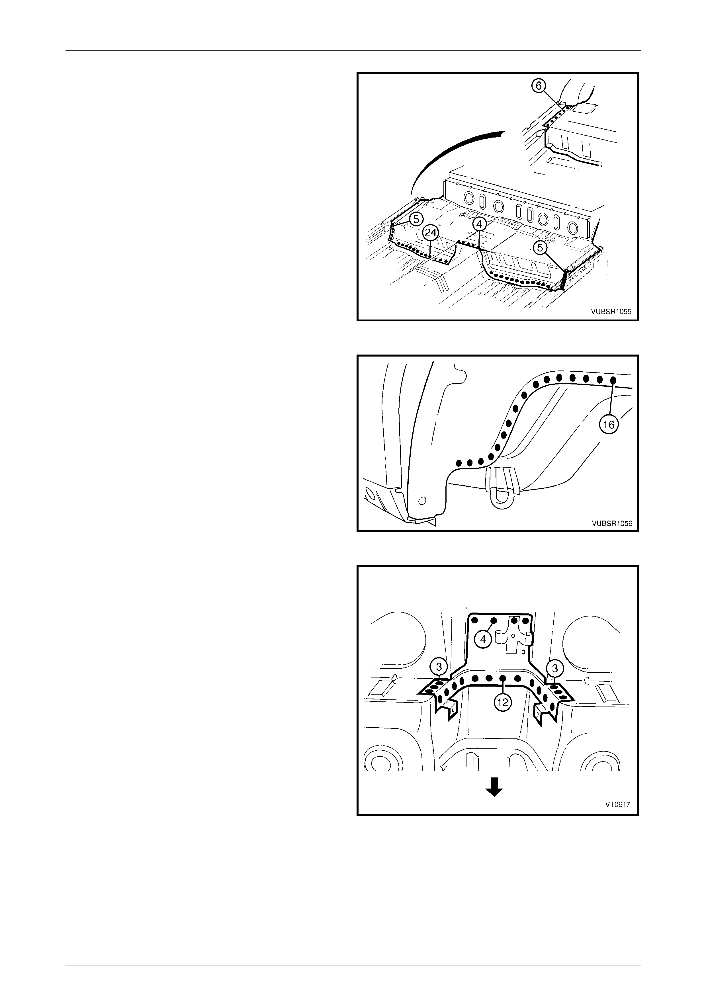
4 Spot or plug weld the rear end lo wer panel to the tail
lamp housing.
5 MIG weld one place 55 mm (1) and two places 30 mm
(2), the rear end lower panel to the quarter panel
extension.
6 Spot or plug weld the rear end lo wer panel to the rear
end panel and the side inn er upper panel, refer to
Figure 10C – 9.
Figure 10C – 8
Figure 10C – 9
7 Refinish and paint panels and other components as required. Refer to Section 3 Body Construction.
8 Apply Joint Sealer (Item 3) as required. Refer to Section 3C Body Construction – Utility.
9 Apply Cavity Wax (Item 8) as required to the inside of any box sections or areas inaccessible to paint,
refer to Section 3C Body Construction – Utility.
10 Install the remaining components as described in the appr opriate Section of the MY 2005 VZ Service Information.
10C Body Rear – Utility Page 10C-7
Page 10C-7
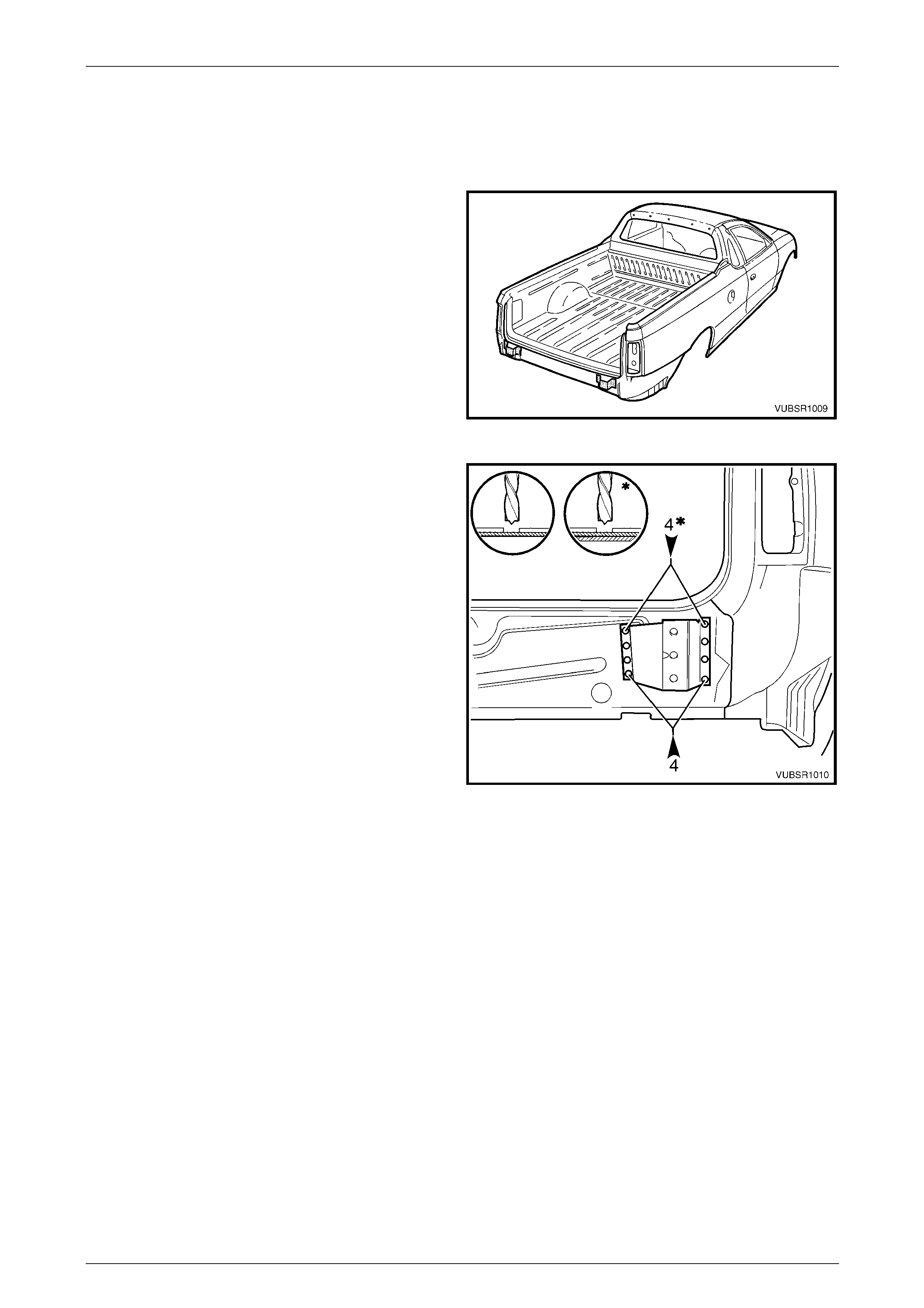
2.2 Endgate Hinge Bracket Assembly –
Replace
Remove
1 Remove the adjacent bolt-on panels and components
as described in the appropriate Section of th e MY
2005 VZ Service Information.
2 Remove the rear end lo wer panel,
refer to 2.1 Rear End Lower Panel – Replac e.
Figure 10C – 10
3 Spot cut the four lower welds attaching the endgate
hinge bracket assembly to the rear end panel.
4 Spot cut the four upper welds attaching the endgate
hinge bracket assembly to the rear end pan el and rear
side rail assembly.
NOTE
Cut through the rear end panel as well if it is to
be removed.
5 Remove the endgate hinge br acket assembly then
repair any damage to adjacen t parts as required.
Figure 10C – 11
10C Body Rear – Utility Page 10C-8
Page 10C-8
Replace
NOTE
• Spot welding is the preferred method for
attaching of panels and should be used
whenever possible. Where the spot welding
equipment available will not access the
required weld position, a plug weld should be
performed.
• The same number and position of spot welds
(or plug welds) should be used when
replacing the panel, as was used during
manufacture, in order to maintain the original
structural strength of the vehicle.
1 As required, mark the new panel with drilling locations in preparation for plug welding. Drill holes as req uired.
2 Prepare all mating surfaces and treat with Weld Through Primer (Item 1) as requir ed,
refer to Section 3C Body Construction – Utility.
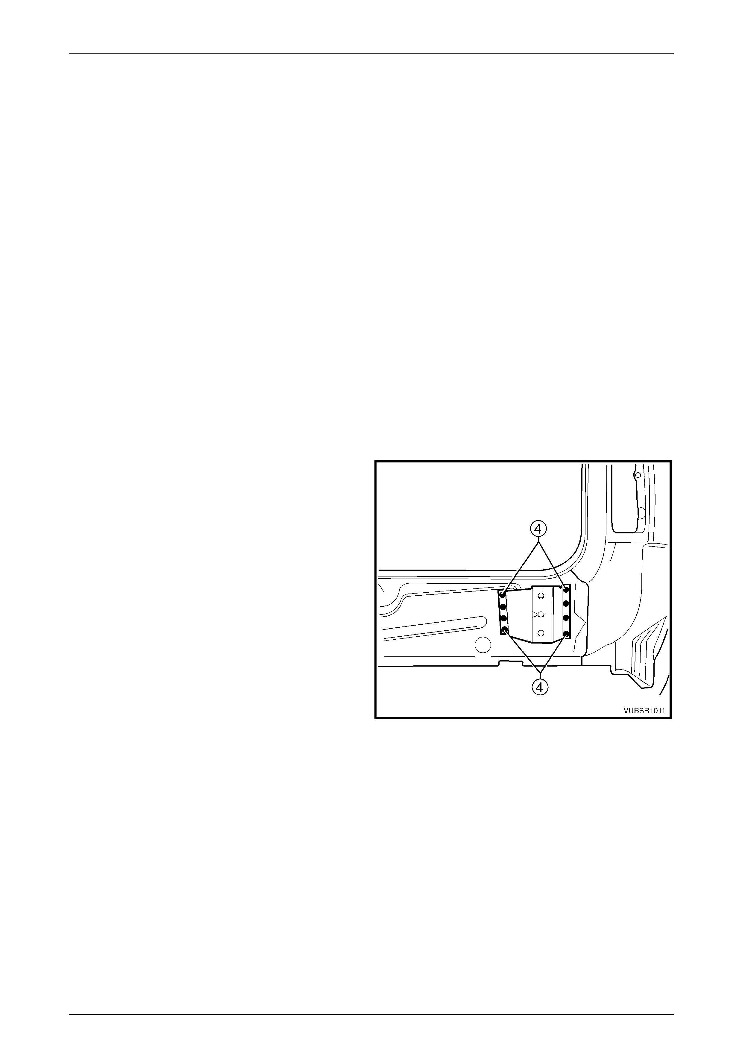
3 Install the endgate hinge bracket assembly in position on the rear end panel.
NOTE
Test fit the rear end lower panel to ensure the
endgate hinge mounting holes align.
4 Spot or plug weld the four upper welds attaching the
endgate hinge bracket assembly to the rear end panel
and rear side rail assembly.
5 Spot or plug weld the four lower welds attaching
endgate hinge bracket assembly to the rear end panel.
6 Install the rear end lower panel,
refer to 2.1 Rear End Lower Panel – Replac e.
7 Refinish and paint panels and other components as
required. Refer to Section 3 Body Construction .
8 Apply Joint Sealer (Item 3) as required.
Refer to Section 3C Body Construction – Utilit y.
9 Apply Cavity Wax (Item 8) as required to the inside of
any box sections or areas i na ccessible to paint,
refer to Section 3C Body Construction – Utility.
10 Install the remaining components as described in the
appropriate Section Service Informatio n. Figure 10C – 12
10C Body Rear – Utility Page 10C-9
Page 10C-9
2.3 Rear End Panel – Replace
Remove
NOTE
This procedure describes the removal of the rear
end lower panel, endgate hinge brack et assembl y
and rear end panel as an assembly. As the
panels are supplied individually, this procedure
contains the replacement of the rear end panel
only. Reference should be then made to
2.2 Endgate Hinge Bracket Assembly – Replace
and 2.1 R ear End Lo wer Panel – Replace f or the
relevant replacement procedures of the
remaining panels.
1 Remove the adjacent bolt-on panels and components
as described in the appropriate Section of th e MY
2005 VZ Service Information.
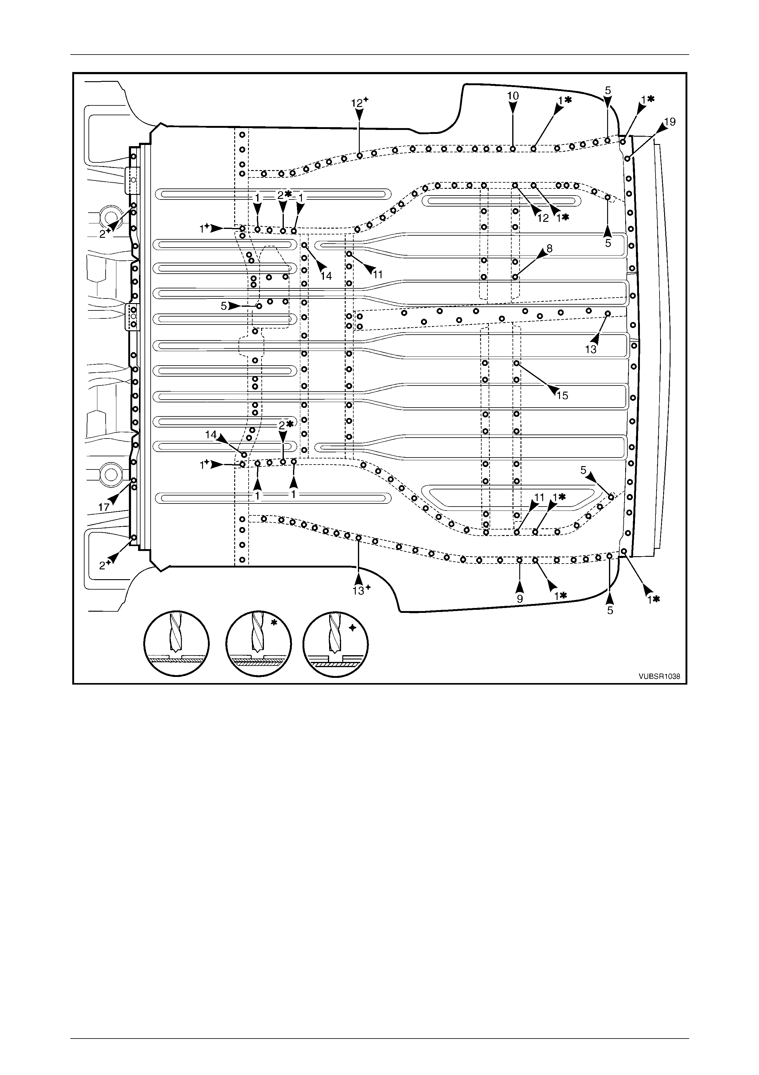
2 From underneath the vehicle, spot cut the welds
attaching the rear end panel assembly to the load floor
centre rail assembly, rear side rail assembl y and side
inner upper panel each side, refer to Figure 10C – 14
Figure 10C – 13
Figure 10C – 14
10C Body Rear – Utility Page 10C-10
Page 10C-10
3 Grind off the three MIG welds (1) and (2) attaching the
rear end lower panel to the quarter panel e xtension.
4 Spot cut the welds attaching the rear end lower panel
to the quarter panel extension.
5 Referring to Figure 10C – 16:
• Spot cut the three welds each side attaching the
rear end lower panel to the quarter lo wer rear
panel,
• Spot cut the weld each side attaching the rear
end panel and load floor p anel to the quarter
lower rear panel,
• Grind off the MIG weld each side (A) attaching
the rear end panel to the quarter lower rear
panel,
• Spot cut the welds attaching the load floor panel
to the rear end panel.
6 Remove the rear end panel assembl y from the vehicle
and repair any dama ge to adjacent parts as required.
Figure 10C – 15
Figure 10C – 16
10C Body Rear – Utility Page 10C-11
Page 10C-11
Replace
NOTE
• Spot welding is the preferred method for
attaching of panels and should be used
whenever possible. Where the spot welding
equipment available will not access the
required weld position, a plug weld should be
performed.
• The same number and position of spot welds
(or plug welds) should be used when
replacing the panel, as was used during
manufacture, in order to maintain the original
structural strength of the vehicle.
1 As required, mark the new panel with drilling locations in preparation for plug welding. Drill holes as req uired.
2 Prepare all mating surfaces and treat with Weld Through Primer (Item 1) as requir ed,
refer to Section 3C Body Construction – Utility.
3 Clamp the rear end panel in position on the vehicle and spot or plug weld to the load floor panel, one place each
side to the load floor panel and quarter l ower rear panel and two places each side to the q uarter lower rear panel,
refer to Figure 10C – 17.
Figure 10C – 17
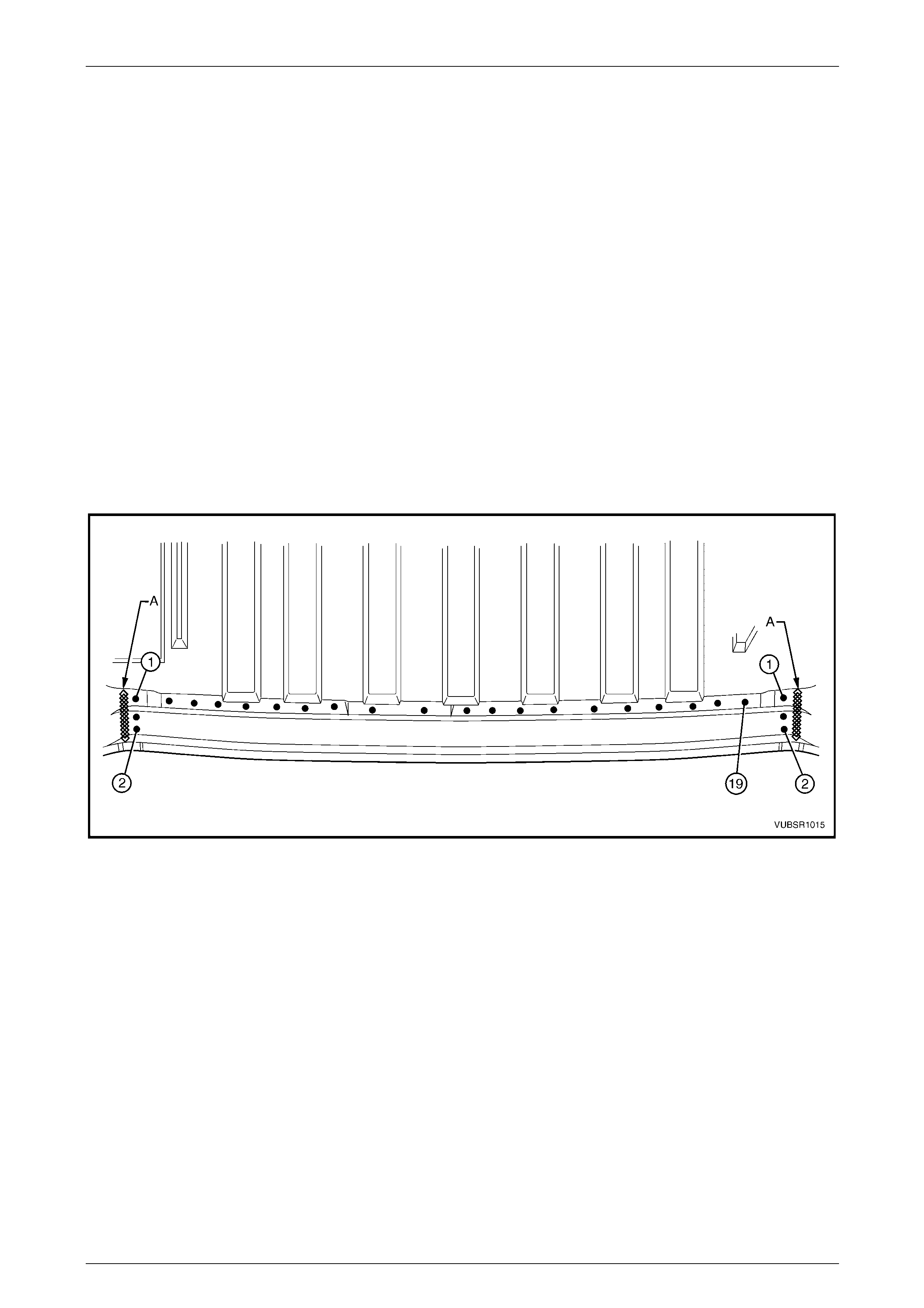
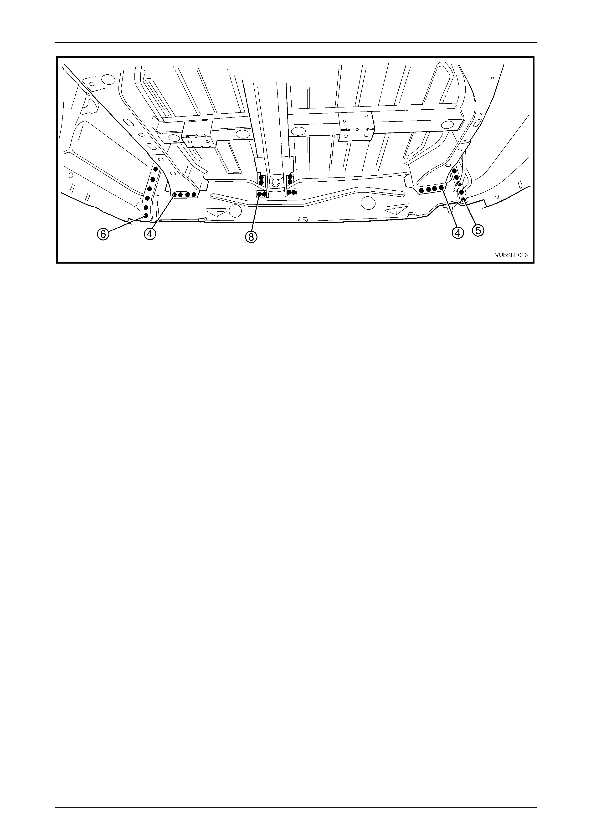
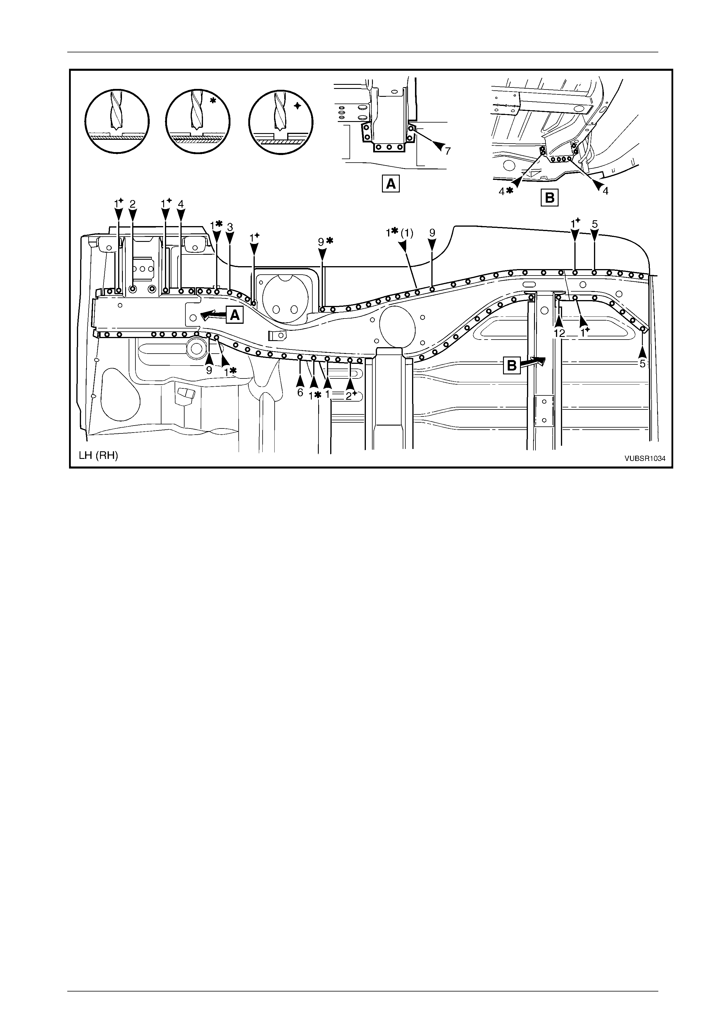
4 Referring to Figure 10C – 18 Spot or plug weld the rear end panel:
• to the side inner upper panel, six places right-hand and five places left-hand,
• to the load floor centre rail assembly, eight places, an d
• to the rear side rail assembly lower flange, four places each side.
NOTE
Do not weld the rear side rail assembly side
flanges until the endgate hinge bracket
assemblies are installed.
10C Body Rear – Utility Page 10C-12
Page 10C-12
Figure 10C – 18
5 Install the endgate hinge bracket assemblies, refer to 2.2 Endgate Hinge Bracket Assembly – Replac e .
6 Clean up the welds and apply primer to any bare metal.
7 Install the rear end lower panel, refer to 2.1 Rear End Lower Panel – Replace.
8 Refinish and paint panels and other components as required. Refer to Section 3 Body Construction.
9 Apply Joint Sealer (Item 3) as required. Refer to Section 3C Body Construction – Utility.
10 Apply Cavity Wax (Item 8) as required to the inside of any box secti ons or areas inaccessible to paint, refer to
Section 3C Body Construction – Utility.
11 Install the remaining components as described in the appr opriate Section of the MY 2005 VZ Service Information.
10C Body Rear – Utility Page 10C-13
Page 10C-13
2.4 Load Floor Centre Rail Assembly –
Replace
Remove
1 Remove the adjacent bolt-on panels and components
as described in the appropriate Section of th e MY
2005 VZ Service Information.
2 Remove adjacent panels as required, refer to the
appropriate Section in this Supplement.
Figure 10C – 19
3 If required, from underneath the vehicle spot cut the
welds attaching the spare wheel support to the load
floor centre rail.
4 Spot cut the welds attaching the load floor centre rail
to the crossmember assembly No. 2.
Figure 10C – 20
5 Spot cut the welds attaching the load floor centre rail
to the left-hand and right-hand load floor reinforcement
rails.
6 If required, spot cut the welds attaching the load floor
centre rail to the rear end panel.
7 Spot cut the welds attaching the load floor centre rail
to the load floor panel, refer to Figure 10C – 22.
8 Remove the load floor centre rail from the ve hicle and
repair any damage to adjacen t parts as required.
Figure 10C – 21
10C Body Rear – Utility Page 10C-14
Page 10C-14
Figure 10C – 22
Replace
NOTE
• Spot welding is the preferred method for
attaching of panels and should be used
whenever possible. Where the spot welding
equipment will not access the required weld
position, a plug weld should b e performed.
• The same number and position of spot welds
(or plug welds) should be used when
replacing the panel, as was used during
manufacture, in order to maintain the original
structural strength of the vehicle.
1 As required, mark the new panel with drilling locations in preparation for plug welding. Drill holes as req uired.
2 Prepare all mating surfaces and treat with Weld Through Primer (Item 1) as required,
refer to Section 3C Body Construction – Utility.
3 Spot or plug weld the load floor centre rail to the load floor panel, refer to Figure 10C – 23.
Figure 10C – 23
10C Body Rear – Utility Page 10C-15
Page 10C-15
4 Spot or plug weld the load floor centre rail to the left-
hand and right-hand load floor reinforcement rails.
5 If required, spot or plug weld the load floor centre rai l
to the rear end panel.
Figure 10C – 24
6 Spot or plug weld the load floor centre rail to the
crossmember assembly No. 2.
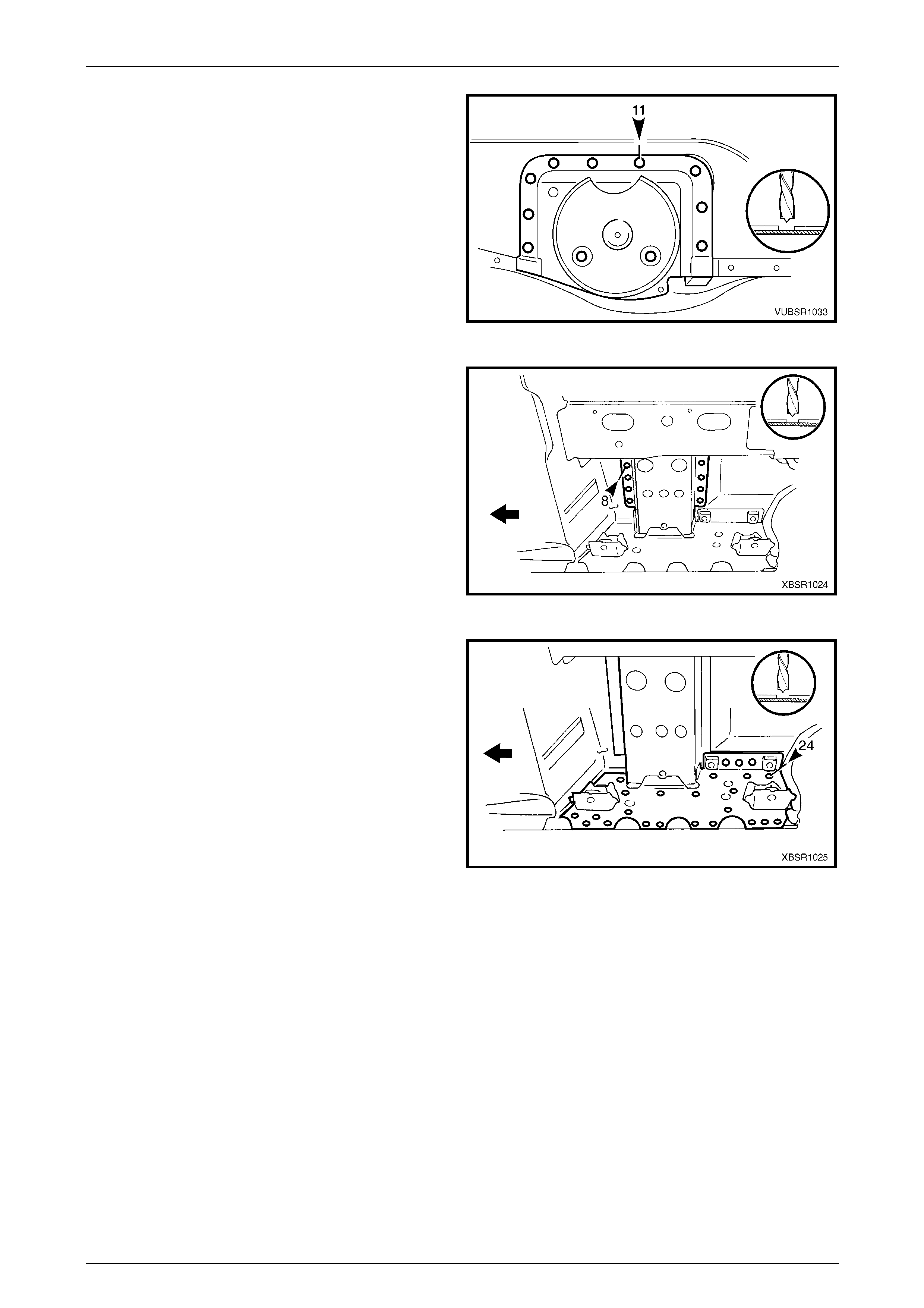
7 Install the spare wheel support, aligning it to the front
of the right-hand flange (1) of the load floor centre rail.
Spot or plug weld four places.
8 Install any removed panels as required, refer to the
appropriate Section in this Supplement.
9 Refinish and paint panels and other components as
required. Refer to Section 3 Body Construction .
10 Apply Joint Sealer (Item 3) as requir ed. Refer to
Section 3C Body Construction – Utility.
11 Apply Cavity Wax (Item 8) as required to the inside of
any box sections or areas inaccessible to paint, refer
to Section 3C Body Construction – Util ity.
12 Install the remaining components as described in the
appropriate Section of the MY 2005 VZ Service
Information. Figure 10C – 25
10C Body Rear – Utility Page 10C-16
Page 10C-16
2.5 Load Floor Reinforcement Rail Assembly
– Replace
Remove
1 Remove the adjacent bolt-on panels and components
as described in the appropriate Section of th e MY
2005 VZ Service Information.
2 Secure the vehicle on a suitable fixture. As a
minimum, support the appropriate structural s ections
of the vehicle on safety stands.
Figure 10C – 26
3 If required, from each side remove the spot welds
attaching the spare wheel sup port to the load floor
reinforcement rail.
4 Spot cut the welds attaching the load floor
reinforcement rail to the rear side rail assembly.
Figure 10C – 27
5 Spot cut the welds attaching the load floor
reinforcement rail to the load floor centre ra il
assembly.
6 Spot cut the two welds attaching the load floor
reinforcement rail to the load floor centre ra il
assembly, refer to Figure 10C – 29.
7 Spot cut the eight welds right-hand or 15 welds left-
hand, attaching each load floor reinforcement rail to
the load floor panel, refer to Figure 10C – 29.
8 Remove the load floor reinforcement rail from the
vehicle and repair any damag e to adjacent parts as
required.
Figure 10C – 28
10C Body Rear – Utility Page 10C-17
Page 10C-17
Figure 10C – 29
Replace
NOTE
• Spot welding is the preferred method for
attaching of panels and should be used
whenever possible. Where the spot welding
equipment available will not access the
required weld position, a plug weld should be
performed.
• The same number and position of spot welds
(or plug welds) should be used when
replacing the panel, as was used during
manufacture, in order to maintain the original
structural strength of the vehicle.
1 As required, mark the new panel with drilling locations in preparation for plug welding. Drill holes as req uired.
2 Prepare all mating surfaces and treat with Weld Through Primer (Item 1) as requir ed,
refer to Section 3C Body Construction – Utility.
3 Install the load floor reinforcement rail no tin g its positio n from the front of the load floor centre rail flange, refer to
Figure 10C – 30.
4 Plug weld two places, the load floor rei nforcement rail to the load floor centre rail, refer to Figure 10C – 30.
5 Plug weld eight places right-hand or 15 pl aces left-hand, the load floor reinforcement rail to the load floor panel,
refer to Figure 10C – 30.
10C Body Rear – Utility Page 10C-18
Page 10C-18
Figure 10C – 30
6 Plug weld the load floor reinforcement rai l to the rear
side rail assembly.
Figure 10C – 31
7 Plug weld the load floor reinforcement rai l to the load
floor centre rail.
8 Install the left-hand or right-hand spar e wheel support
on the load floor reinforcement rail in the position
shown, refer to Figure 10C – 33 and plug weld two
places each side.
Figure 10C – 32
10C Body Rear – Utility Page 10C-19
Page 10C-19
Figure 10C – 33
9 Install any removed panels as required, refer to the appropriate Section i n this Supplement.
10 Refinish and paint panels and other components as required. Refer to Section 3 Body Construction.
11 Apply Joint Sealer (Item 3) as required. Refer to Section 3C Body Construction – Utility.
12 Apply Cavity Wax (Item 8) as required to the inside of any box sections or ar eas inaccessible to paint, refer to
Section 3C Body Construction – Utility.
13 Install the remaining components as described in the appr opriate Section of the MY 2005 VZ Service Information.
10C Body Rear – Utility Page 10C-20
Page 10C-20
2.6 Crossmember Assembly No. 2 – Replace
Remove
1 Remove the adjacent components as described in the
appropriate Section of the MY 2005 VZ Service
Information.
2 Secure the vehicle on a suitable fixture. As a
minimum, support the appropriate structural s ections
of the vehicle on safety stands.
Figure 10C – 34
3 Spot cut the welds attaching the crossmember No.2 to
the crossmember bracket and to the rear side rai l, on
each side of the vehicle.
NOTE
Take care not to damage the crossmember
brackets when removing the crossmember, as
these parts are only serviced as part of the rear
side rail assemblies.
Figure 10C – 35
4 Spot cut the welds attaching the crossmember to the
load floor panel.
5 Remove the crossmember from the vehicle, and then
repair any damage to adjacen t parts as required.
6 Check and rectify the alignme nt of
the body as required, refer to
Section 3C Body Construction – Utility.
Figure 10C – 36
10C Body Rear – Utility Page 10C-21
Page 10C-21
Replace
NOTE
• Spot welding is the preferred method for
attaching of panels and should be used
whenever possible. Where the spot welding
equipment will not access the required weld
position, a plug weld should b e performed.
• The same number and position of spot welds
(or plug welds) should be used when
replacing the panel, as was used during
manufacture, in order to maintain the original
structural strength of the vehicle.
1 As required, mark the new panel with drilling locations in preparation for plug welding. Drill holes as req uired.
2 Prepare all mating surfaces and treat with Weld Through Primer (Item 1) as required,
refer to Section 3C Body Construction – Utility.
3 Plug weld the crossmember to the crossmember
bracket and rear side rail, on each side of the vehicle.
Figure 10C – 37
4 Plug weld the crossmember to the load floor pan el.
5 Refinish and paint panels and other components as
required. Refer to Section 3 Body Construction .
6 Apply Joint Sealer (Item 3) as required.
Refer to Section 3C Body Construction – Utilit y.
7 Apply Cavity Wax (Item 8) as required to the inside of
any box sections or areas i na ccessible to paint,
refer to Section 3C Body Construction – Utility.
8 Apply Spray-on Deadener (Item 7) where applicable,
refer to Section 3C Body Construction – Utility.
9 Install the remaining components as described in the
appropriate Section of the MY 2005 VZ Service
Information. Figure 10C – 38

10C Body Rear – Utility Page 10C-22
Page 10C-22
2.7 Rear Floor Panel Outer Extension –
Replace
Remove
1 Remove the adjacent bolt-on panels and components
as described in the appropriate Section of th e MY
2005 VZ Service Information.
Figure 10C – 39
2 Spot cut the welds attaching the rear floor panel outer
extension to the inner rocker panel and rear side rail
assembly and remove.
Figure 10C – 40
Replace NOTE
• Spot welding is the preferred method for
attaching of panels and should be used
whenever possible. Where the spot welding
equipment will not access the required weld
position, a plug weld should b e performed.
• The same number and position of spot welds
(or plug welds) should be used when
replacing the panel, as was used during
manufacture, in order to maintain the original
structural strength of the vehicle.
1 As required, mark the new panel with drilling locations in preparation for plug welding. Drill holes as req uired.
2 Prepare all mating surfaces and treat with Weld Through Primer (Item 1) as requir ed,
refer to Section 3C Body Construction – Utility.
3 Install and plug weld the rear floor panel outer
extension to the inner rocker panel and rear side rail
assembly.
4 Refinish and paint panels and other components as
required. Refer to Section 3 Body Construction .
5 Apply Cavity Wax (Item 8) as required to the inside of
any box sections or areas i na ccessible to paint,
refer to Section 3C Body Construction – Utility.
6 Install the remaining components as described in the
appropriate Section of the MY 2005 VZ Service
Information.
Figure 10C – 41

10C Body Rear – Utility Page 10C-23
Page 10C-23
2.8 Rear Tie Down Assembly – Replace
Remove
1 Remove the adjacent components as described in the
appropriate Section of the MY 2005 VZ Service
Information.
Figure 10C – 42
2 Spot cut the welds attaching the tie down assembly to
the rear side rail assembly and remove.
Figure 10C – 43
Replace NOTE
• Spot welding is the preferred method for
attaching of panels and should be used
whenever possible. Where the spot welding
equipment will not access the required weld
position, a plug weld should b e performed.
• The same number and position of spot welds
(or plug welds) should be used when
replacing the panel, as was used during
manufacture, in order to maintain the original
structural strength of the vehicle.
1 As required, mark the new panel with drilling locations in preparation for plug welding. Drill holes as req uired.
2 Prepare all mating surfaces and treat with Weld Through Primer (Item 1) as requir ed,
refer to Section 3C Body Construction – Utility.
3 Install the tie down assembly onto the rear side rail
assembly, approximately 9 mm rearward of the join.
4 Plug weld the tie down assembly to the rear side rail
assembly, eight places.
5 Refinish and paint panels and other components as
required. Refer to Section 3 Body Construction .
6 Apply Cavity Wax (Item 8) as required to the inside of
any box sections or areas inaccessible to paint, refer
to Section 3C Body Construction – Util ity.
7 Install the remaining components as described in the
appropriate Section of the MY 2005 VZ Service
Information.
Figure 10C – 44
10C Body Rear – Utility Page 10C-24
Page 10C-24
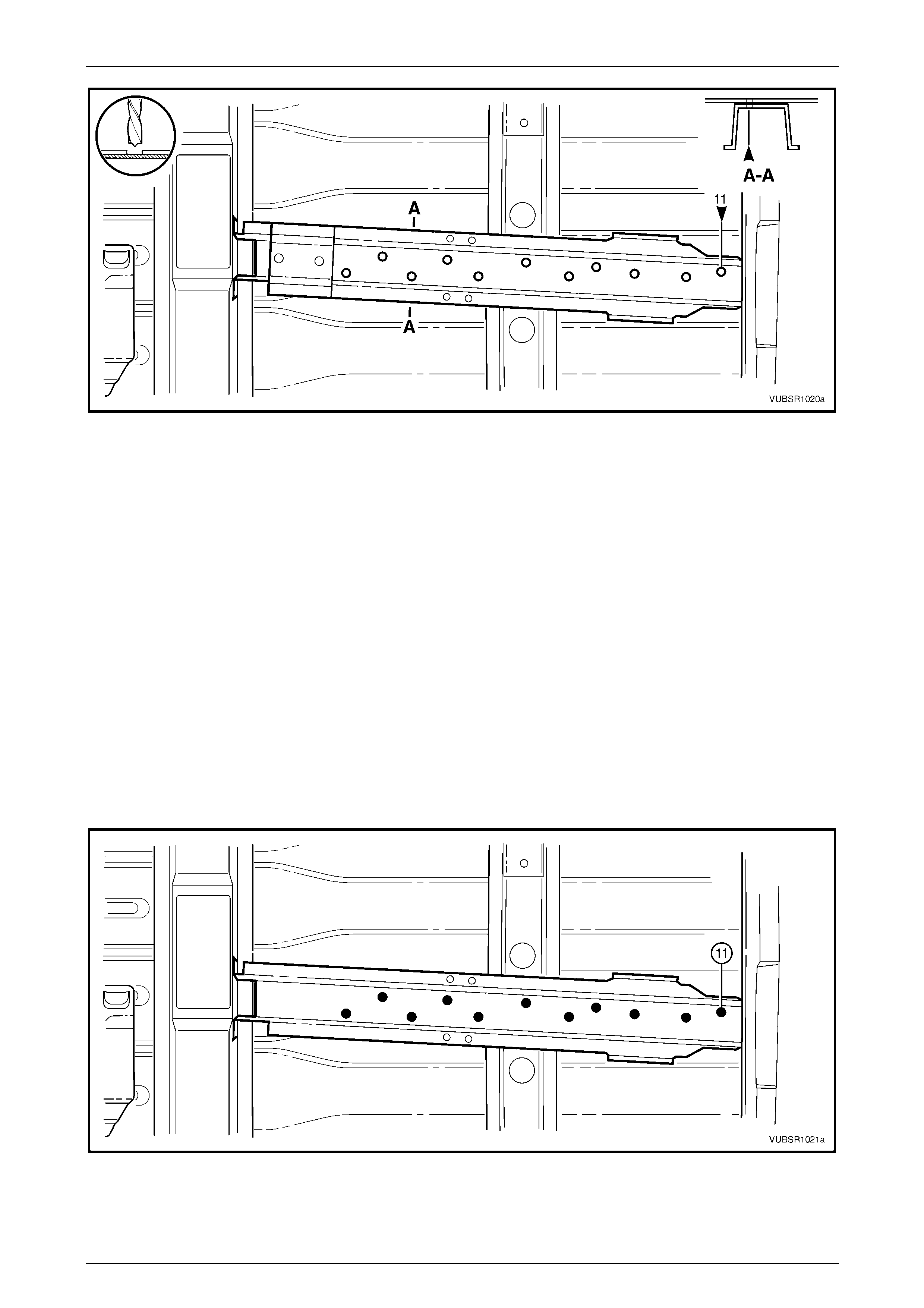
2.9 Rear Side Rail Assembly – Replace
Remove
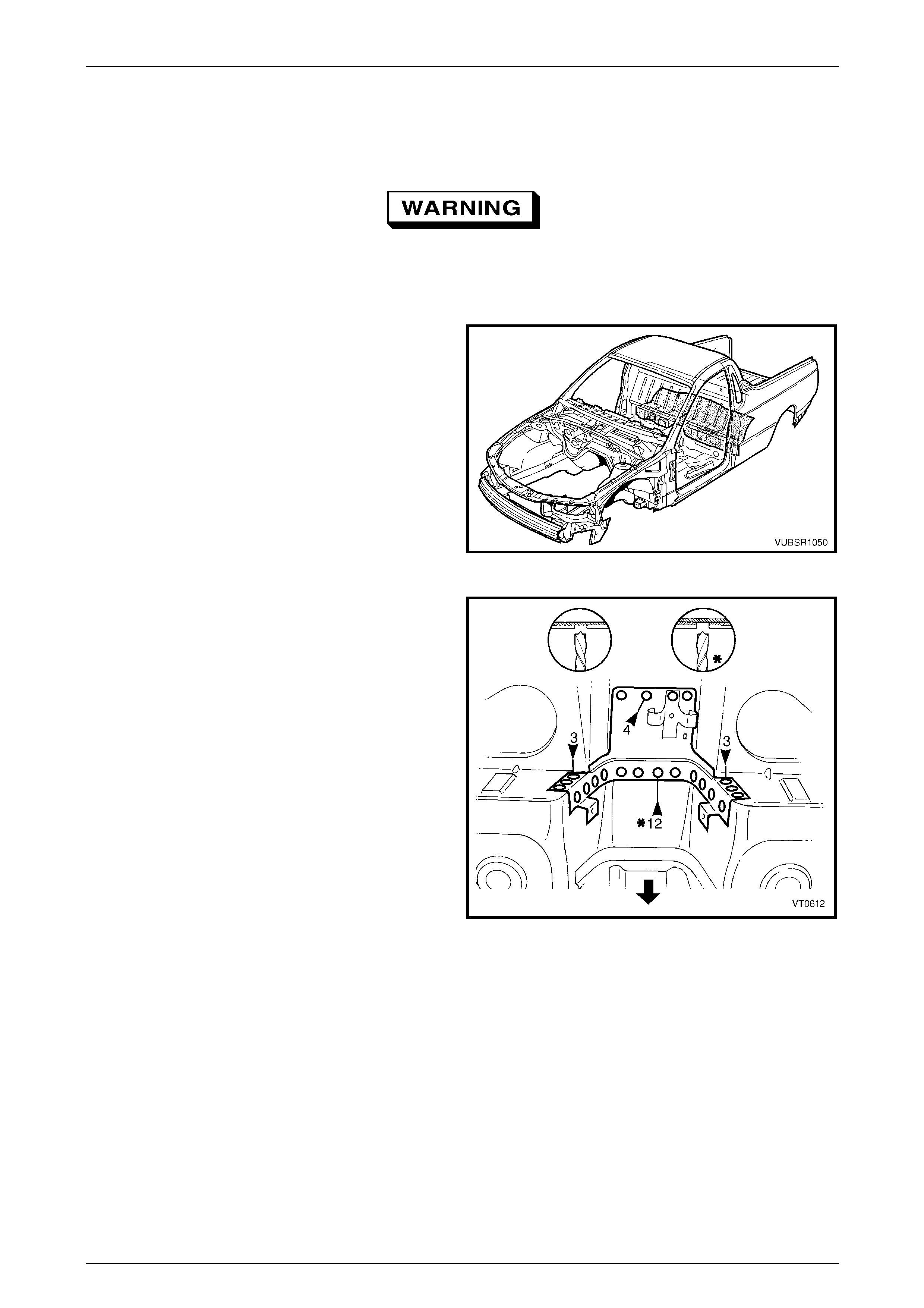
To avoid the possibility of fire, take particular
care when cuttin g or w elding at the rear of the
vehicle. Remove the fuel tank and plug all fuel
lines.
1 Remove the adjacent components as described in the
appropriate Section of the MY 2005 VZ Service
Information.
2 Secure the vehicle on a suitable fixture. As a
minimum, support the appropriate structural s ections
of the vehicle on safety stands. Ensure that the stands
are clear of the rear side rail assembly(s) being
removed.
Figure 10C – 45
3 Spot cut the welds attaching the load floor
reinforcement rail to the rear side rail assembly.
Figure 10C – 46
4 Spot cut the welds attaching the crossmember No.2 to
the crossmember bracket and to the rear side rai l.
Figure 10C – 47
10C Body Rear – Utility Page 10C-25
Page 10C-25
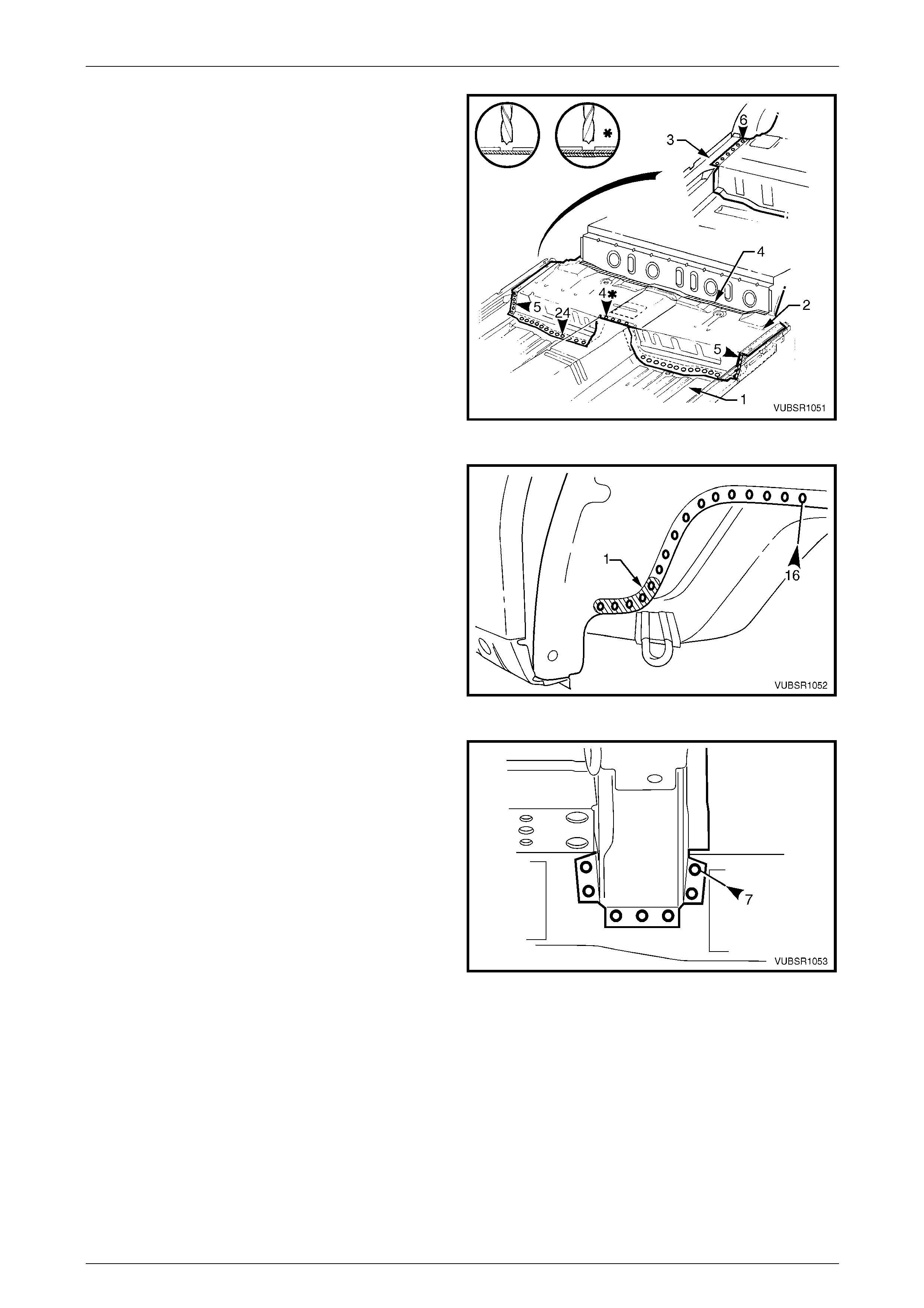
5 Spot cut the welds attaching the rear side rail
assembly to the load floor panel.
Figure 10C – 48
6 Spot cut the welds attaching the rear side rail
assembly to the rear floor panel assembly.
Figure 10C – 49
7 Spot cut the welds attaching the rear floor panel outer
extension to the inner rocker panel assembly.
8 Spot cut the rear side rail assembly from the load floor
panel, rear end panel and rear floor panel assembly,
refer to Figure 10C – 51.
9 Remove the rear side rail assembly from the vehicle
and repair damage to adjacent parts as required.
10 Check and rectify the alignment of
the body as required, refer to
Section 3C Body Construction – Utility.
Figure 10C – 50
10C Body Rear – Utility Page 10C-26
Page 10C-26
Figure 10C – 51
Replace
NOTE
• Spot welding is the preferred method for
attaching of panels and should be used
whenever possible. Where the spot welding
equipment will not access the required weld
position, a plug weld should b e performed.
• The same number and position of spot welds
(or plug welds) should be used when
replacing the panel, as was used during
manufacture, in order to maintain the original
structural strength of the vehicle.
1 As required, mark the new panel with drilling locations in preparation for plug welding. Drill holes as req uired.
2 Prepare all mating surfaces and treat with Weld Through Primer (Item 1) as requir ed,
refer to Section 3C Body Construction – Utility.
3 Locate and clamp the new rear side rail assembly in position.
4 Check and adjust the alignment of the rear side rail assembly as required,
refer to Section 3C Body Construction – Utility.
5 Plug weld the rear side rail assembly to the load floor panel, rear end panel and rear floor panel assembly, refer to
Figure 10C – 52.
10C Body Rear – Utility Page 10C-27
Page 10C-27
Figure 10C – 52
6 Plug weld the rear side rail assembly to the load floor
panel.
Figure 10C – 53
7 Plug weld the rear side rail assembly to the r ear floor
panel assembly and the rear floor panel outer
extension to the inner rocker panel assembly.
Figure 10C – 54

10C Body Rear – Utility Page 10C-28
Page 10C-28
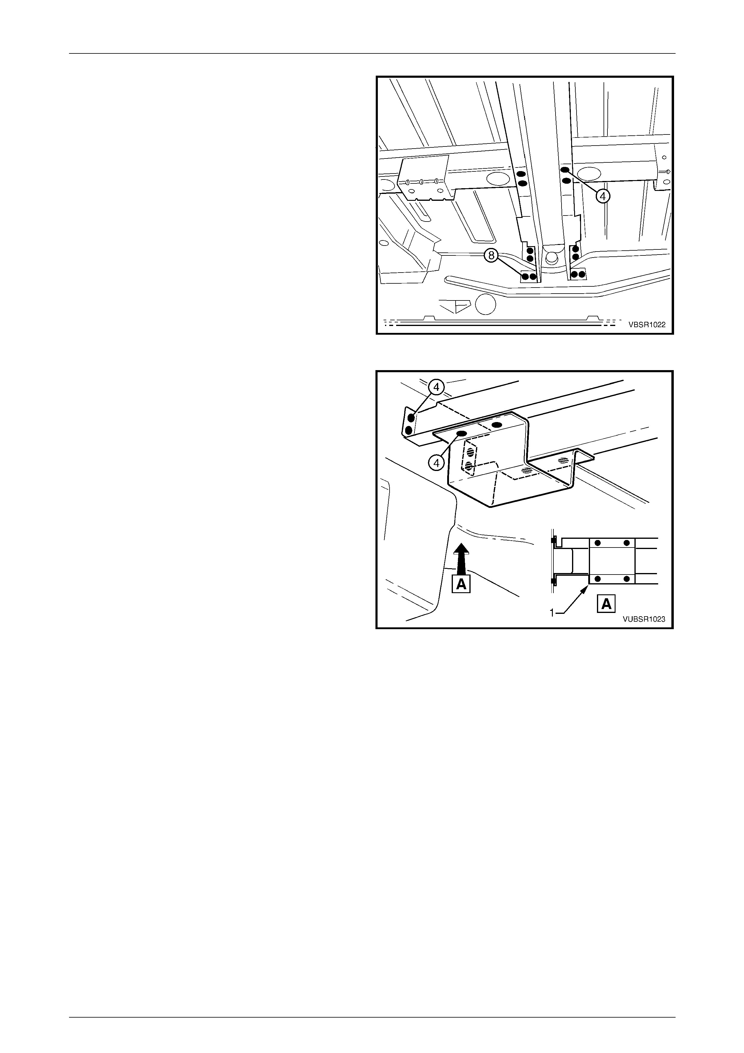
8 Plug weld the crossmember assembly No. 2 to the
crossmember bracket and rear side rail.
Figure 10C – 55
9 Plug weld the load floor reinforcement rai l to the rear
side rail assembly.
10 Refinish and paint panels and other components as
required. Refer to Section 3 Body Construction .
11 Apply Joint Sealer (Item 3) as required.
Refer to Section 3C Body Construction – Utility.
12 Apply Cavity Wax (Item 8) as required to the inside of
any box sections or areas i na ccessible to paint,
refer to Section 3C Body Construction – Utility.
13 Install the remaining components as described in the
appropriate Service Information.
Figure 10C – 56
10C Body Rear – Utility Page 10C-29
Page 10C-29
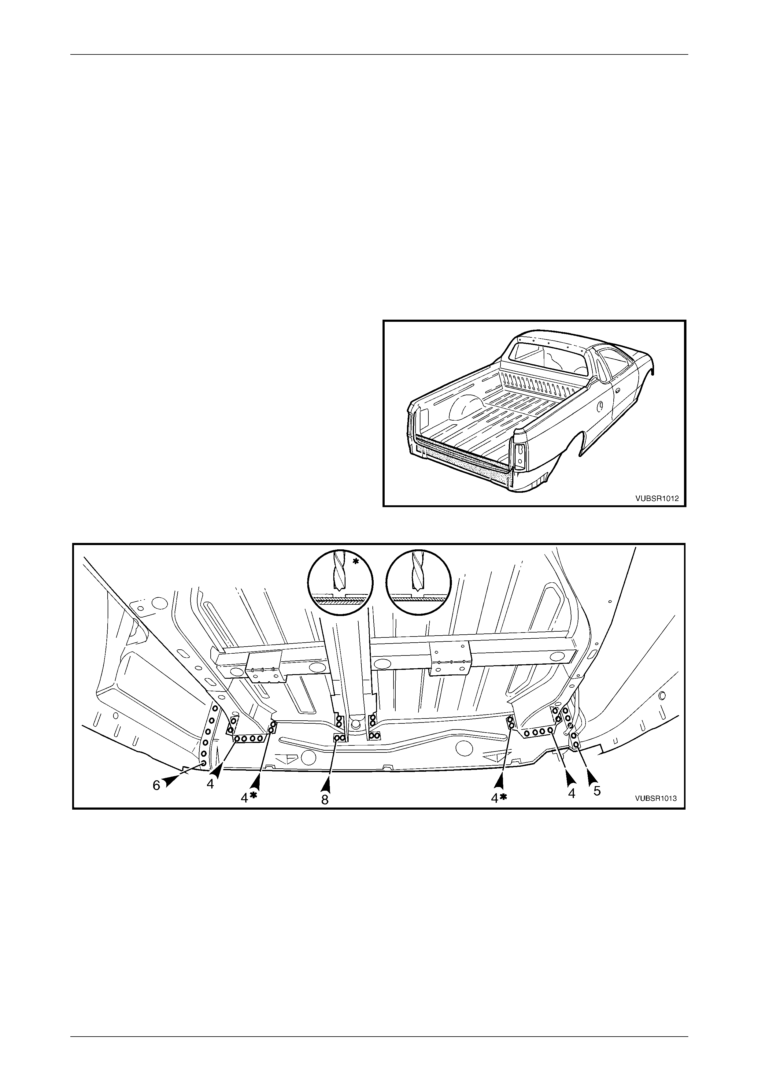
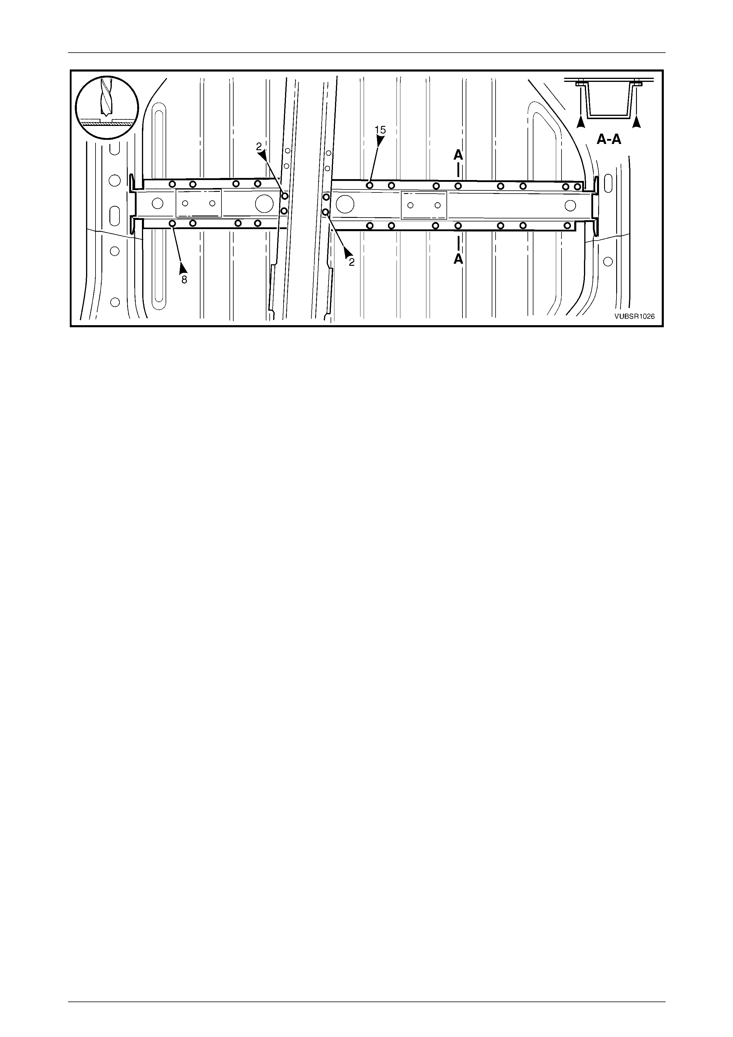
2.10 Load Floor Panel Assembly – Replace
Remove
To avoid the possibility of fire, take particular
care when cuttin g or w elding at the rear of the
vehicle. Remove the fuel tank and plug the
fuel lines.
NOTE
This procedure describes the removal of the load
floor panel, load floor panel reinforcements and
fuel tank brackets as an assembly. As these
components are serviced separately, their
installation is described as they would be
replaced.
1 Remove the adjacent bolt-on panels and components
as described in the appropriate Section of th e MY
2005 VZ Service Information.
2 Secure the vehicle on a suitable fixture. As a
minimum, support the appropriate structural s ections
of the vehicle on safety stands. Ensure that the stands
are clear of the sections being removed.
3 Remove the sealer and floor deadener panels from the
relevant areas using a scrape r and heat gun.
4 Remove the adjoining panels as required, refer to the
appropriate Section of this Supplement.
Figure 10C – 57
5 Referring to Figure 10C – 58:
• Spot cut the weld attaching the load floor panel to the left-hand side i nner upper panel, one place.
• Spot cut the welds attaching the load floor panel to the left-hand side inner upper panel a nd quarter outer
lower rear panel, seven places.
• Grind off the MIG welds (1) attaching the load floor panel to the left-hand side inner upper panel, four places.
• From underneath the vehicle, spot cut the welds attaching the load floor panel to the left-hand rear
wheelhouse inner panel, five places.
• From underneath the vehicle, spot cut the welds attaching the load floor pane l and load floor panel
reinforcement to the left-hand rear wheelhouse inner panel, five places.
Figure 10C – 58
10C Body Rear – Utility Page 10C-30
Page 10C-30
6 Referring to Figure 10C – 59:
• Spot cut the weld attaching the load floor panel to the right-hand sid e inner upper panel, one place.
• Spot cut the welds attaching the load floor panel to the right-hand side inner upper panel and quarter outer
lower rear panel, seven places.
• Grind off the MIG welds (1) attaching the load floor panel to the right-hand side inner upper panel, two places.
• From underneath the vehicle, spot cut the welds attaching the load floor panel to the right-hand rear
wheelhouse inner panel, five places.
• From underneath the vehicle, spot cut the welds attaching the load floor pane l and load floor panel
reinforcement to the right-hand rear wheelhouse inner panel, twelve places.
Figure 10C – 59
7 Spot cut the welds attaching the load floor panel to the
rear wheelhouse inn er panel each side of the vehicle.
8 Spot cut the welds attaching the load floor panel to the
load floor panel outer extension, each side of the
vehicle.
9 Spot cut the welds attaching the load floor panel to the
rear side rail assemblies, rear end panel, load floor
centre rail assembly, left-hand and right-hand load
floor reinforcement rails, crossmember asse mbly No. 2
and rear floor panel assembly, refer to
Figure 10C – 61.
Figure 10C – 60
10C Body Rear – Utility Page 10C-31
Page 10C-31
Figure 10C – 61
10 Remove the load floor panel and repair any damage to ad jacent parts as required.
NOTE
Structural adhesive is applied to the front mating
surface of the load floor panel where it attaches
the rear floor – panel assembly, which may
require cutting.
11 Check and rectify the alignme nt of the body as required, refer to Section 3C Body Construction – Utility.
10C Body Rear – Utility Page 10C-32
Page 10C-32
Replace
NOTE
• Spot welding is the preferred method for
attaching of panels and should be used
whenever possible. Where the spot welding
equipment will not access the required weld
position, a plug weld should b e performed.
• The same number and position of spot welds
(or plug welds) should be used when
replacing the panel, as was used during
manufacture, in order to maintain the original
structural strength of the vehicle.
1 As required, mark the new panel with drilling locations in preparation for plug welding. Drill holes as req uired.
2 Prepare all mating surfaces and treat with Weld Through Primer (Item 1) as requir ed,
refer to Section 3C Body Construction – Utility.
3 Prior to installing the load floor panel, install the fuel tank mounting br ackets and the left-hand and right-hand loa d
floor panel reinforcements as descri bed below.
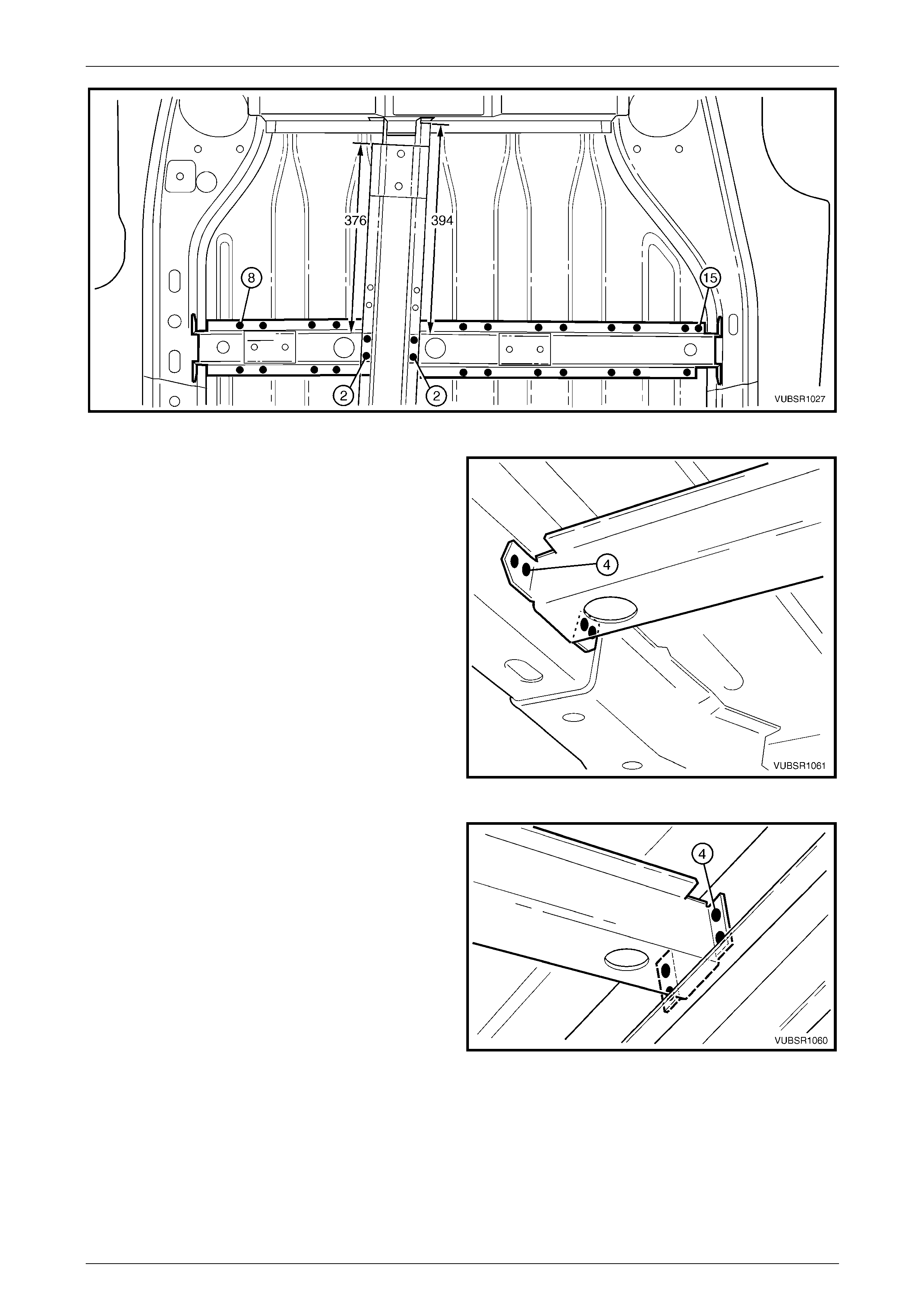
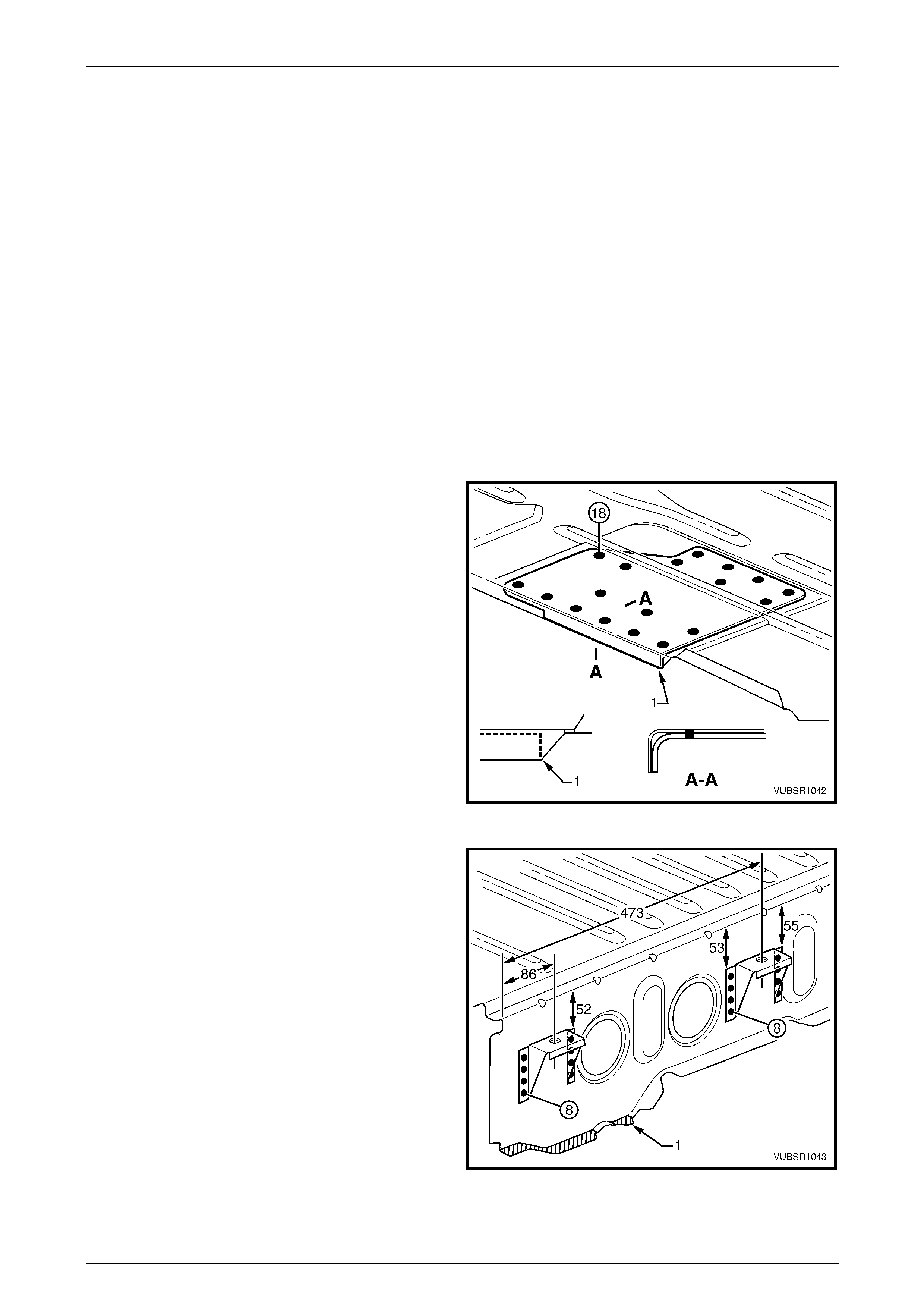
4 Fit the load floor panel reinforcement to the und erside
of the load floor panel, aligning the front corn er as
shown (1).
5 Spot or plug weld the reinforcement to the load floor
panel 18 places.
6 Repeat for the opposite side.
Figure 10C – 62
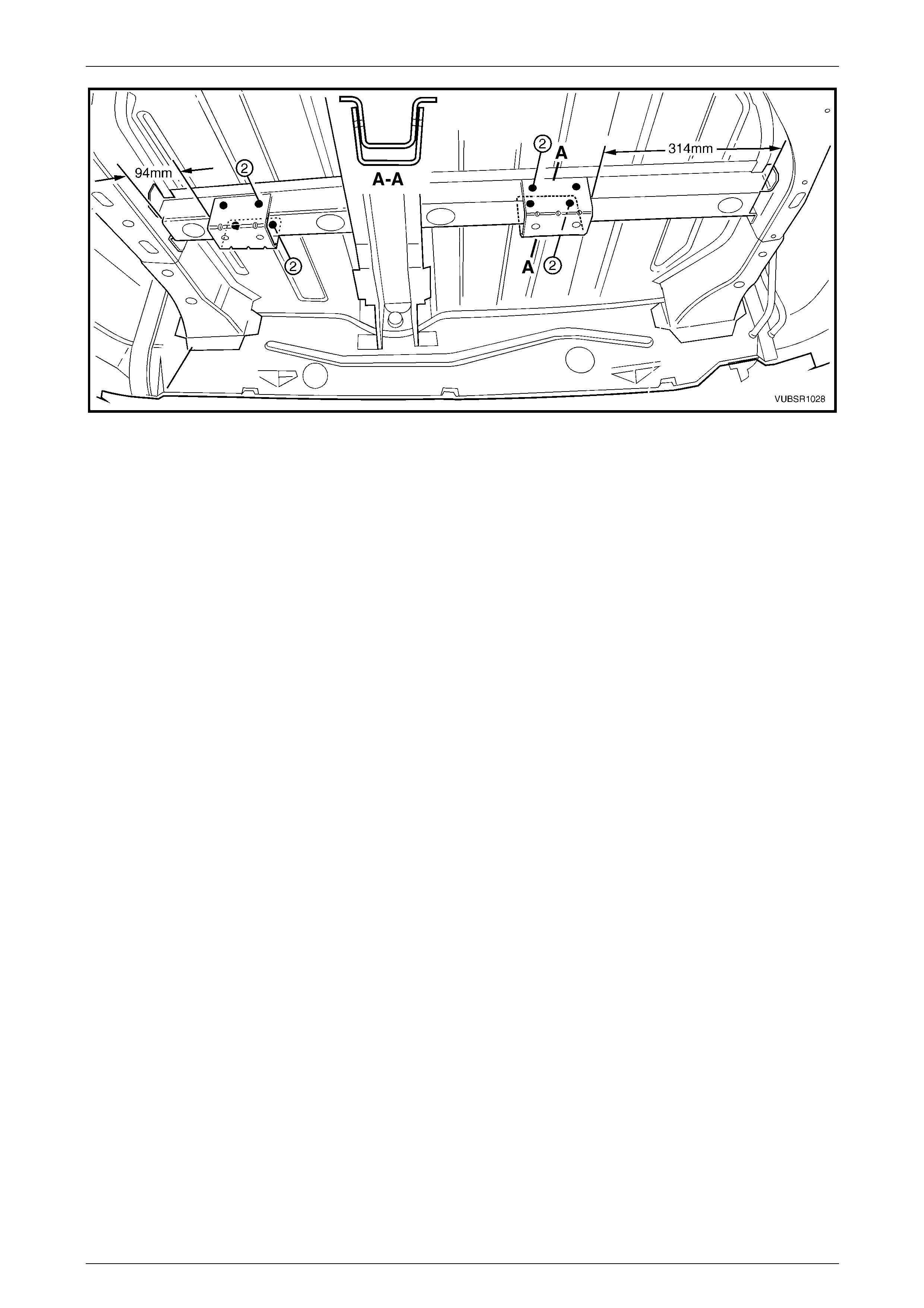
7 Position the fuel tank mounting brackets on to the load
floor panel, ensuring they are aligned to the
dimensions shown.
8 Spot or plug weld the brackets to the load floor panel,
eight places each.
9 Apply Structural Adhesive (Item 6), to the
front mating surface of the load floor panel, refer to
Section 3C Body Construction – Utility.
10 Install the load floor panel and clamp in position.
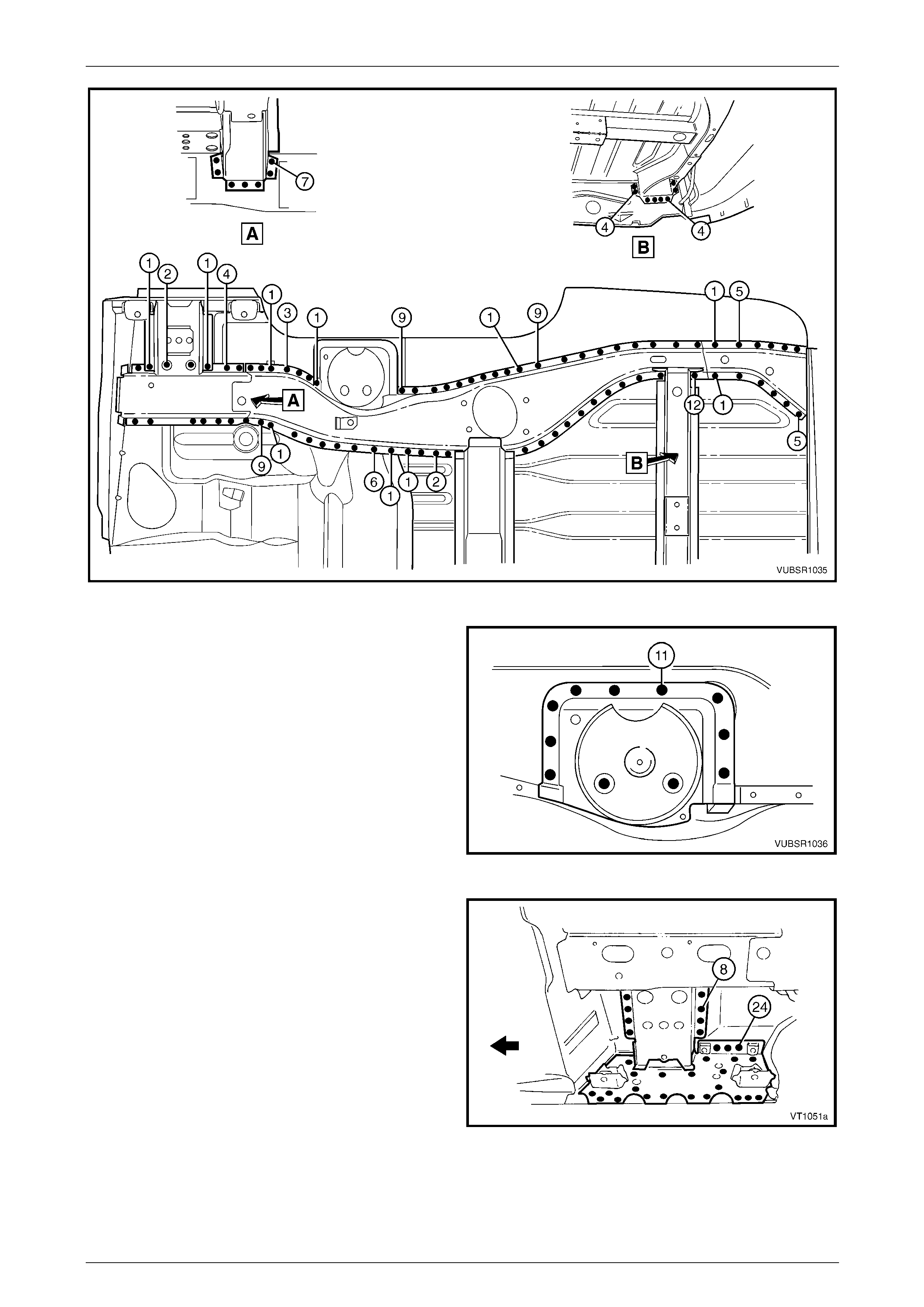
11 Beginning at the front, spot or plug weld the load floor
panel to the rear floor panel assembl y, cross m ember
assembly No. 2, left-hand and right-hand load floor
reinforcement rails, load floor centre rail assembly,
rear end panel and rear side rail assemblies, refer to
Figure 10C – 64.
Figure 10C – 63
10C Body Rear – Utility Page 10C-33
Page 10C-33
Figure 10C – 64
12 Spot or plug weld five places the load floor panel to
the rear wheelhouse inner panel each side of the
vehicle.
13 Spot or plug weld three places the load floor panel to
the load floor panel outer extension each side of the
vehicle.
Figure 10C – 65
10C Body Rear – Utility Page 10C-34
Page 10C-34
14 Spot or plug weld the load floor panel to the left-hand
side inner upper panel, one p lace.
15 Spot or plug weld the load floor panel to the left-hand
side inner upper panel and quarter outer lower rear
panel, seven places.
16 MIG weld (1) the load floor panel to the left-hand sid e
inner upper panel, four places.
17 From underneath the vehicle, spot or plug weld the
load floor panel to the left-hand rear wheelhouse inner
panel, five places.
18 From underneath the vehicle, spot or plug weld the
load floor panel and load floor panel reinforcement to
the left-hand rear wheelhouse inner panel, five places.
Figure 10C – 66
19 Spot or plug weld the load floor panel to the right-hand
side inner upper panel, one p lace.
20 Spot or plug weld the load floor panel to the right-hand
side inner upper panel and quarter outer lower rear
panel, seven places.
21 MIG weld (1) the load floor panel to the right-hand side
inner upper panel, two places.
22 From underneath the vehicle, spot or plug weld the
load floor panel to the right-hand rear wheelhouse
inner panel, five places.
23 From underneath the vehicle, spot or plug weld the
load floor panel and load floor panel reinforcement to
the right-hand rear wheelho use inner panel, 12 pl aces.
24 Install any removed panels as required, refer to the
appropriate Section in this Supplement.
Figure 10C – 67
25 Refinish and paint panels and other components as required. Refer to Section 3 Body Construction.
26 Apply Joint Sealer (Item 3) as required. Refer to Section 3C Body Construction – Utility.
27 Apply Cavity Wax (Item 8) as required to the inside of any box sections or ar eas inaccessible to paint, refer to
Section 3C Body Construction – Utility.
28 Install the remaining components as described in the appr opriate Section of the MY 2005 VZ Service Information.
10C Body Rear – Utility Page 10C-35
Page 10C-35
2.11 Rear Floor Panel – Replace
Remove
To avoid the possibility of fire, take particular
care when cuttin g or w elding at the rear of the
vehicle. Remove the fuel tank and plug the
fuel lines.
1 Remove the adjacent components as described in the
appropriate Section of the MY 2005 VZ Service
Information.
2 Secure the vehicle on a suitable fixture. As a
minimum, support the appropriate structural s ections
of the vehicle on safety stands. Ensure that the stands
are clear of the sections being removed.
3 Remove the adjoining panels as required, refer to the
appropriate Section of this Supplement.
Figure 10C – 68
4 Spot cut the welds attaching the park brake cabl e
bracket to the rear floor panel assembly.
Figure 10C – 69
10C Body Rear – Utility Page 10C-36
Page 10C-36
5 Spot cut the welds joining the front floor panel
assembly (1) and rear floor panel assembly (2).
6 Spot cut the welds attaching the rear floor panel
assembly to the inner rocker panel (3) each side.
NOTE
Structural adhesive is applied in the area
shown (4).
Figure 10C – 70
7 Spot cut the welds attaching the rear floor panel
assembly to the rear wheelhouse inner panel on each
side of the vehicle.
NOTE
Structural adhesive is applied in the area
shown (1).
Figure 10C – 71
8 Spot cut the welds attaching the front of each rear side
rail assembly to the rear floor panel assembly.
9 As required, spot cut the welds attaching the rear floor
panel assembly to the rear side rail assemblies and
load floor panel, refer to Figure 10C – 73.
NOTE
Depending on what other panels are removed,
these welds can be cut from above or
underneath the vehicle as required, underside
shown.
10 Remove the rear floor panel assembly from the vehicle
and then repair any damage t o adjacent parts as
required.
11 Check and rectify the alignment of
the body as required, refer to
Section 3C Body Construction – Utility.
Figure 10C – 72
10C Body Rear – Utility Page 10C-37
Page 10C-37
Figure 10C – 73
Replace
NOTE
• Spot welding is the preferred method for
attaching of panels and should be used
whenever possible. Where the spot welding
equipment will not access the required weld
position, a plug weld should b e performed.
• The same number and position of spot welds
(or plug welds) should be used when
replacing the panel, as was used during
manufacture, in order to maintain the original
structural strength of the vehicle.
1 As required, mark the new panel with drilling locations in preparation for plug welding. Drill holes as req uired.
2 Prepare all mating surfaces and treat with Weld Through Primer (Item 1) as requir ed,
refer to Section 3C Body Construction – Utility.
3 Apply Structural Adhesive (Item 6), refer to Section 3C Bod y Constructio n – Utility.
10C Body Rear – Utility Page 10C-38
Page 10C-38
4 Clamp the new panel in position in the vehicle and
plug weld to the front floor panel assembly and inner
rocker panel each side.
Figure 10C – 74
5 Spot or plug weld the rear floor panel asse mbly to the
rear wheelhouse inner panel on each side of the
vehicle.
Figure 10C – 75
6 Plug weld the park brake cable brack et to the rear
floor panel assembly.
7 As required, spot or plug weld the rear floor pane l
assembly to the rear side rail assemblies and load
floor panel, refer to Figure 10C – 77.
NOTE
Depending on what other panels are removed,
these welds can be made from above or
underneath the vehicle as required, underside
shown.
Figure 10C – 76
10C Body Rear – Utility Page 10C-39
Page 10C-39
Figure 10C – 77
8 Plug weld the front of each rear side rail assembl y to
the rear floor panel assembly.
9 Replace any other remov ed panels, refer to the
appropriate Section of this Supplement.
10 Refinish and paint panels and other components as
required. Refer to Section 3 Body Construction .
11 Apply Joint Sealer (Item 3) as required.
Refer to Section 3C Body Construction – Utility.
12 Apply Cavity Wax (Item 8) as required to the inside of
any box sections or areas i na ccessible to paint,
refer to Section 3C Body Construction – Utility.
13 Apply deadene r panels in accordance with
the original production condition.
Refer to Section 3C Body Construction – Utility.
Figure 10C – 78
14 Apply the fusible reinforcement patch, refer to Section 3C Body Construction – Utility.
15 Apply Spray-on Dea dener (Item 7) where applicab le, refer to Section 3C Body Construction – Utility.
16 Install the remaining components as described in the appr opriate Section of the MY 2005 VZ Service Information.