10E Body Rear – Regular Cab Page 10E–1
Page 10E–1
Section 10E
Body Rear – Regular Cab
ATTENTION
Before performing any service operation or other procedure described in this Section, refer to Section 2
Precautions in this Supplement and Section 00 Warnings, Cautions and Notes in the MY2005 VZ Service
Information for correct workshop practices with regard to safety and/or property damage.
The structure of the body shell has been
developed using complex design and
development techniques. In addition to
meeting all required standards, the vehicle
body is also a critical part of the overall safety
systems. It is therefore imperative the repair
procedures described here are adhered to
during all vehicle body repairs.
1 General Information ...............................................................................................................................2
1.1 Body Rear Components........................................................................................................................................ 2
2 Service Operations.................................................................................................................................3
2.1 Rear Body Lower Panel – Replace....................................................................................................................... 3
Remove................................................................................................................................................................... 3
Replace................................................................................................................................................................... 4
2.2 Rear Body Upper Outer Panel Assembly – Replace........................................................................................... 6
Remove................................................................................................................................................................... 6
Replace................................................................................................................................................................... 7
2.3 Rear Body Upper Inner Panel Assembly – Replace............................................................................................ 9
Remove................................................................................................................................................................... 9
Replace................................................................................................................................................................... 9
10E Body Rear – Regular Cab Page 10E–2
Page 10E–2
1 General Information
This Section describes replacement procedures for the rear compon ents of the Regular Cab body structure. Removal of
bolt-on and mechanical components is not covered. Reference must be made to the appropriate Sections in the MY
2005 VZ Service Information.
For removal of the rear subframe assembly refer to Section 1B Sheetmetal in the MY 2005 VZ Service Information.
NOTE
• When repairing the rear of the vehicle, care
must be taken to ensure the structure is
returned to its original production
configuration.
• It is imperative that the correct body
adhesives, sealers, deadeners and cavity
waxes are used when repairing the body
structure. Refer to Section 3E Body
Construction – Regular Cab for details of the
correct materials and their commercially
available equivalents.
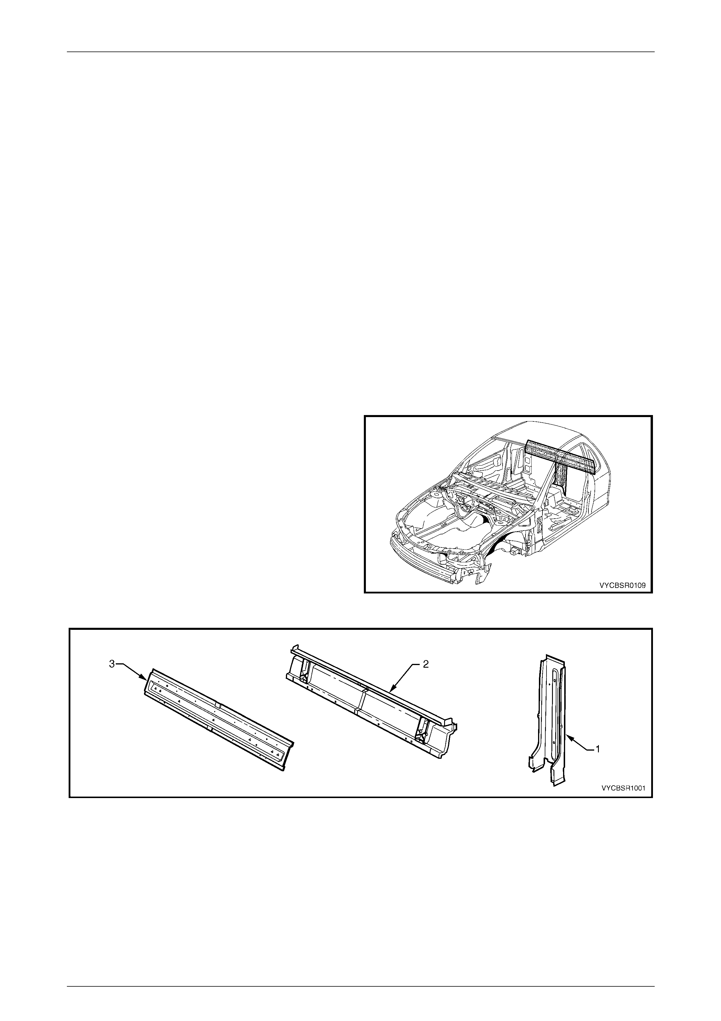
1.1 Body Rear Components
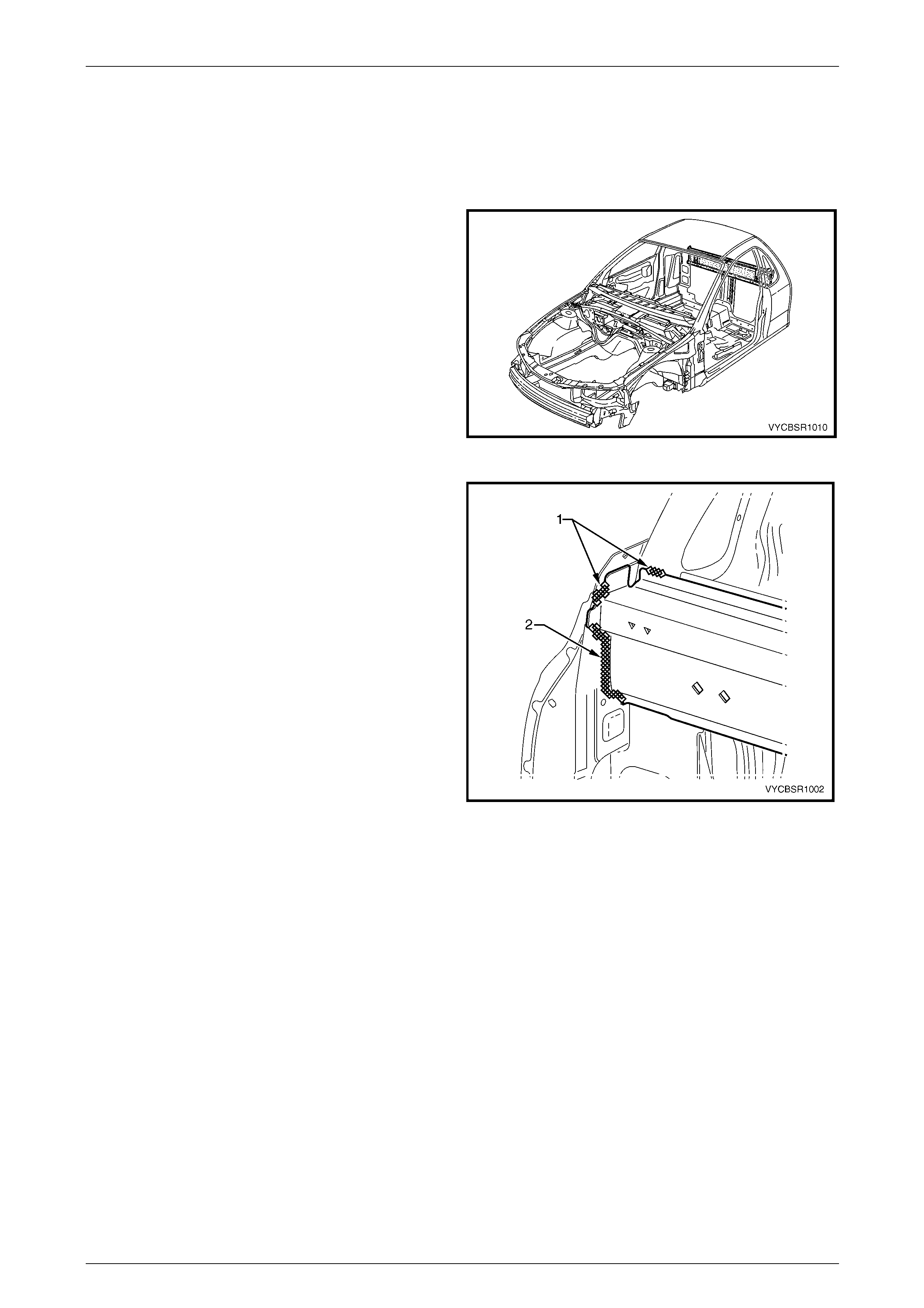
The shaded components in Figure 10E– 1 are those dealt
with in this Section.
The components and assemblies shown in Figure 10E– 2
are the parts serviced for Regular Cab vehicles which form
the basis of the repair procedures in this Secti on.
For a detailed view of the body components, refer to
Section 3E Body Construction – Regular Ca b.
NOTE
Always refer to an Authorised Retailer for spare
parts availability configurations.
Figure 10E– 1
Figure 10E– 2
Legend
1 Rear Body Lower Panel
2 Rear Body Upper Outer Panel Assembly 3 Rear Body Upper Inner Panel Assembly
10E Body Rear – Regular Cab Page 10E–3
Page 10E–3
2 Service Operations
2.1 Rear Body Lower Panel – Replace
Remove
1 Remove the adjacent bolt-on panels a nd components
as described in the appropriate Section of th e MY
2005 VZ Service Information.
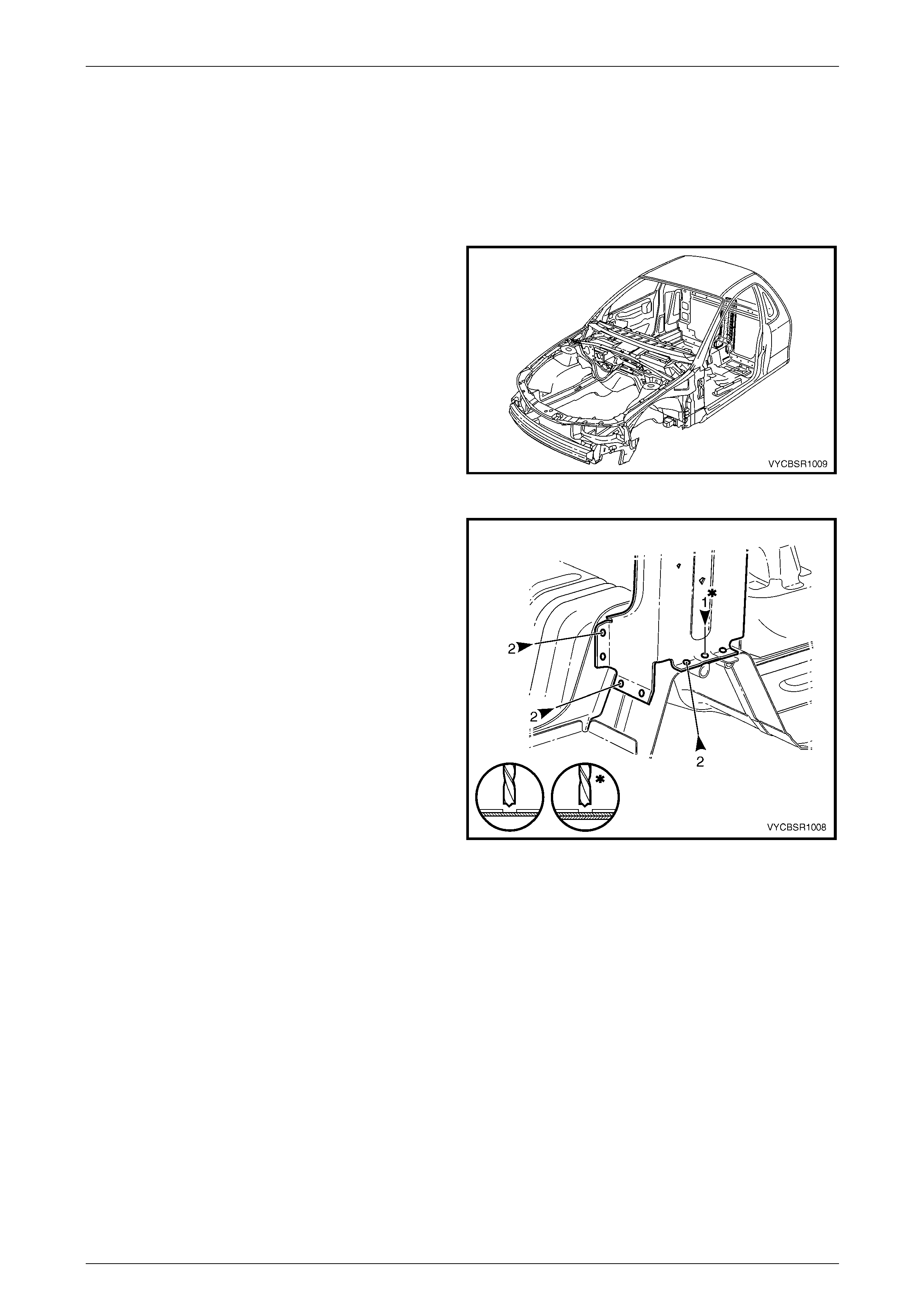
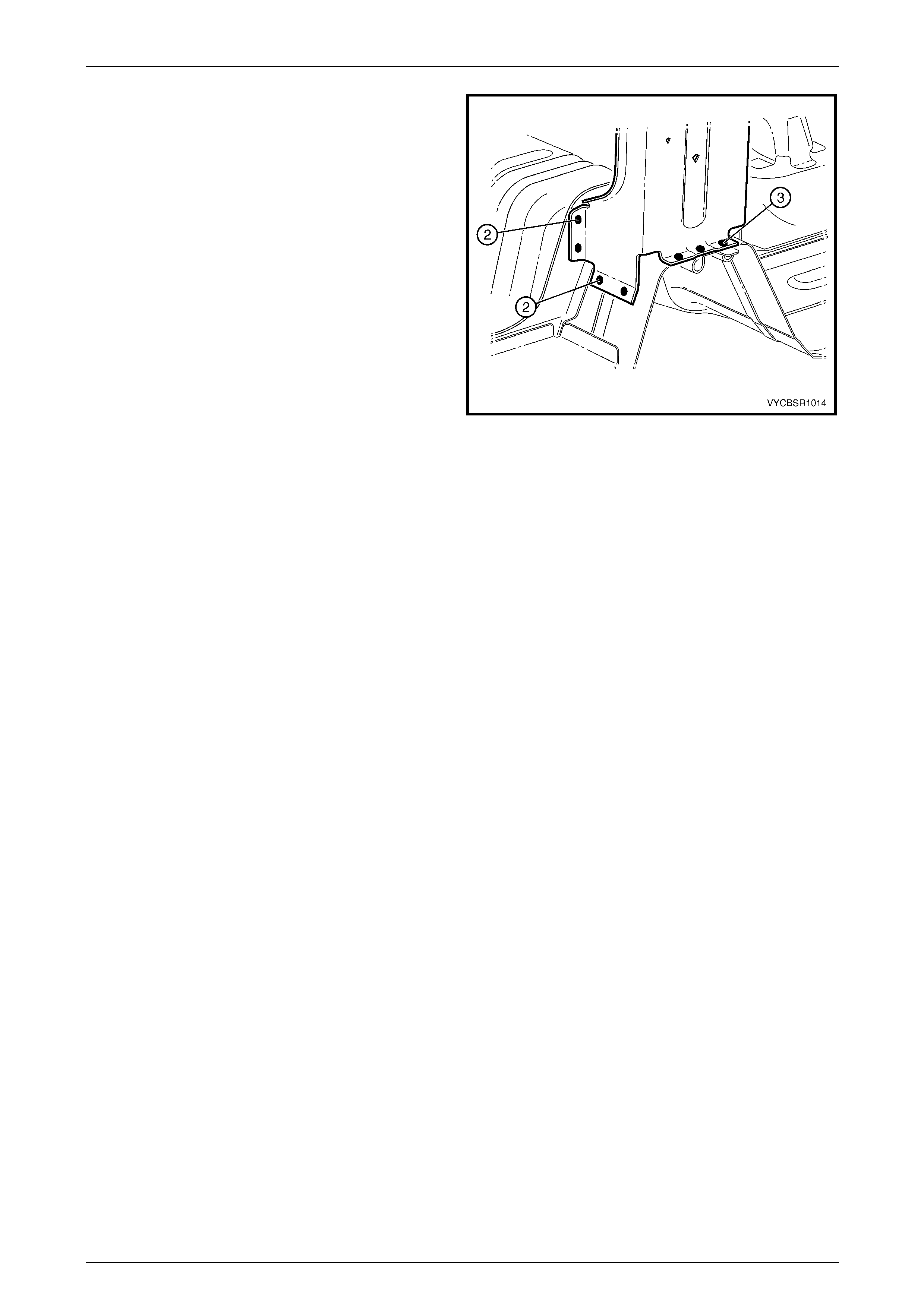
Figure 10E– 3
2 Spot cut the welds, four places on both sides,
attaching the rear body lower panel to the rear end
lower panel and the front floor extension.
3 Spot cut the welds, three places, attaching the body
lower panel to the front floor extension.
Figure 10E – 4
10E Body Rear – Regular Cab Page 10E–4
Page 10E–4
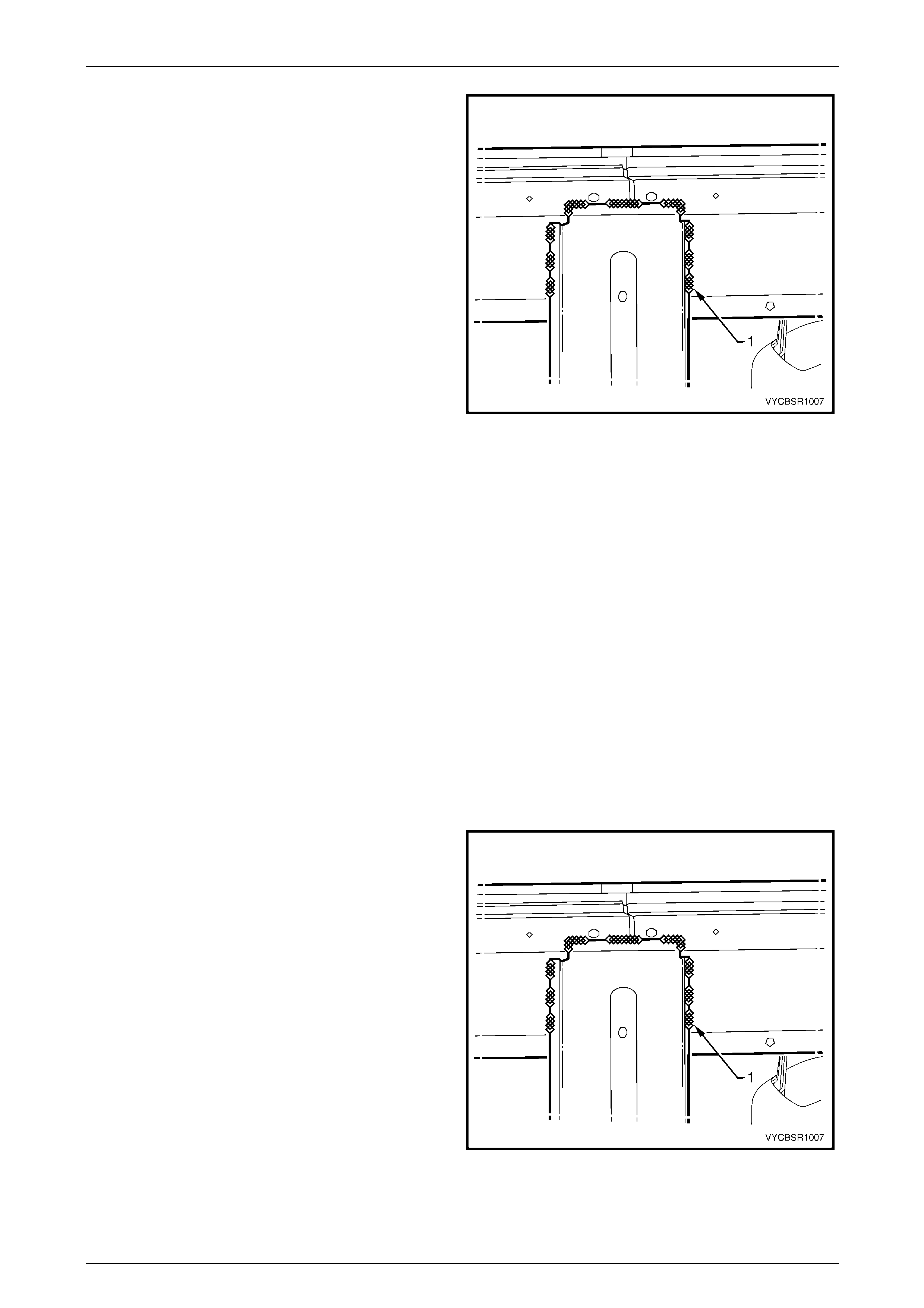
4 Grind off the MIG welds (1), attaching the lower panel
to the rear body upper outer panel assembly.
5 Remove the lower panel from the vehicl e and repair
any damage to adjacent parts as required.
6 Check and rectify the alignme nt of
the body as required, refer to
Section 3E Body Construction – Regular Ca b.
Figure 10E – 5
Replace
NOTE
• Spot welding is the preferred method for
attaching of panels and should be used
whenever possible. Where the spot welding
equipment available will not access the
required weld position, a plug weld should be
performed.
• The same number and position of spot welds
(or plug welds) should be used when
replacing the panel, as was used during
manufacture, in order to maintain the original
structural strength of the vehicle.
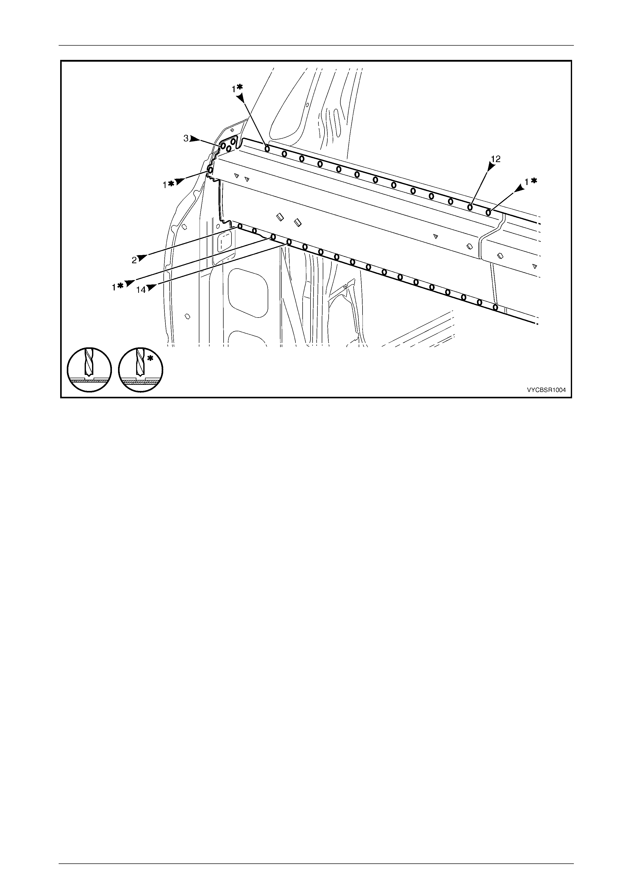
1 As required, mark the new panel with drilling locations in preparation for plug welding. Drill holes as required.
2 Prepare all mating surfaces and treat with Weld Through Primer (Item 1) as required,
refer to Section 3E Body Construction – Regular Cab.
3 Clamp the rear body lower panel in position on the vehicle.
4 MIG weld (1), around the lower panel to the outer
reinforcement.
Figure 10E – 6
10E Body Rear – Regular Cab Page 10E–5
Page 10E–5
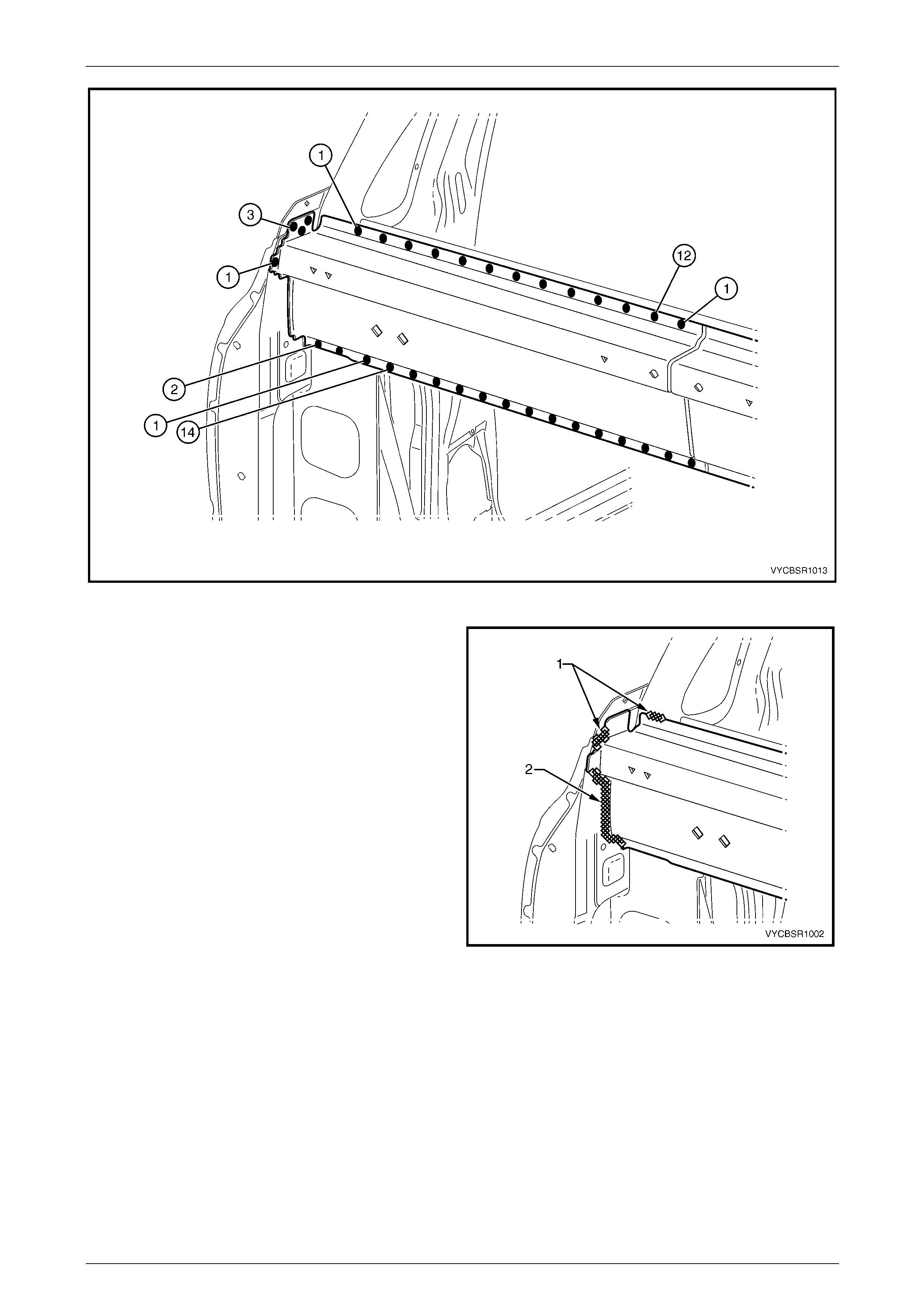
5 Spot or plug weld the body lower panel to the front
floor extension.
6 Spot or plug weld, four places on both sides, the rear
body lower panel to the rear end lower panel and the
front floor extension.
7 Refinish and paint panels and other components as
required. Refer to Section 3 Body Construction .
8 Apply joint sealer (Item 3) as required.
Refer to Section 3E Body Construction – Regular Cab.
9 Apply cavity wax (Item 8) as requ ired to the inside of
any box sections or areas inaccessible to paint,
refer to Section 3E Body Construction – Regular Cab.
10 Install the remaining components as described in the
appropriate Section of the MY 2005 VZ Servic e
Information.
Figure 10E – 7
10E Body Rear – Regular Cab Page 10E–6
Page 10E–6
2.2 Rear Body Upper Outer Panel Assembly
– Replace
Remove
1 Remove the adjacent bolt-on panels a nd components
as described in the appropriate Section of th e MY
2005 VZ Service Information.
2 Remove the rear end lo wer panel,
refer to 2.1 Rear Body Lower Panel – Replace.
Figure 10E – 8
3 Grind off the MIG welds (1) and (2), on each side of
the vehicle, attaching the rear body upper outer pane l
assembly to the side body inner panel.
4 Spot cut the welds on each side of the vehicle,
attaching the rear body upper outer panel assembly to
the rear body upper inner panel and the side body
inner panel, refer to Figure 10E – 10.
NOTE
If the rear body upper inner panel is also to be
removed, spot cut and grind o ff only the relevant
welds.
Figure 10E – 9
10E Body Rear – Regular Cab Page 10E–7
Page 10E–7
Figure 10E – 10
5 Remove the outer reinforcement pane l assembly then repair any damage to adjacent parts as required.
6 Check and rectify the alignme nt of the body as required, ref er to Section 3 E Body Construction – Regular Cab.
Replace
NOTE
• Spot welding is the preferred method for
attaching of panels and should be used
whenever possible. Where the spot welding
equipment available will not access the
required weld position, a plug weld should be
performed.
• The same number and position of spot welds
(or plug welds) should be used when
replacing the panel, as was used during
manufacture, in order to maintain the original
structural strength of the vehicle.
1 As required, mark the new panel with drilling locations in preparation for plug welding. Drill holes as required.
2 Prepare all mating surfaces and treat with Weld Through Primer (Item 1) as requir ed,
refer to Section 3E Body Construction – Regular Cab.
3 Apply Acrylic Spot Weld Sealer (Item 2) as required, refer to Section 3E Body Construction – Reg ul ar Cab.
4 Spot or plug weld on each side of the vehic le , the rear body upper outer reinforcement pa nel assembly to the rear
body upper inner panel and the side body inner panel.
10E Body Rear – Regular Cab Page 10E–8
Page 10E–8
Figure 10E – 11
5 MIG weld (1) and (2), around the outer reinforcement.
6 Install the rear end lower panel, refer to
2.1 Rear Body Lower Panel – Repl ace.
7 Refinish and paint panels and other components as
required. Refer to Section 3 Body Construction .
8 Apply Joint Sealer (Item 3) as required.
Refer to Section 3E Body Construction – Regular Cab.
9 Apply Cavity Wax (Item 8) as required to the inside of
any box sections or areas inaccessible to paint,
refer to Section 3E Body Construction – Regular Cab.
10 Install the remaining components as described in the
appropriate Section of the MY 2005 VZ Servic e
Information.
Figure 10E – 12

10E Body Rear – Regular Cab Page 10E–9
Page 10E–9
2.3 Rear Body Upper Inner Panel Assembly
– Replace
Remove
1 Remove the adjacent bolt-on panels a nd components
as described in the appropriate Section of th e MY
2005 VZ Service Information.
2 Remove the rear end lower panel, refer to
2.1 Rear Body Lower Panel – Repl ace.
3 Remove the rear body outer reinforc ement panel
assembly, refer to 2.2 Rear Body Upper Outer Panel
Assembly – Replace.
Figure 10E – 13
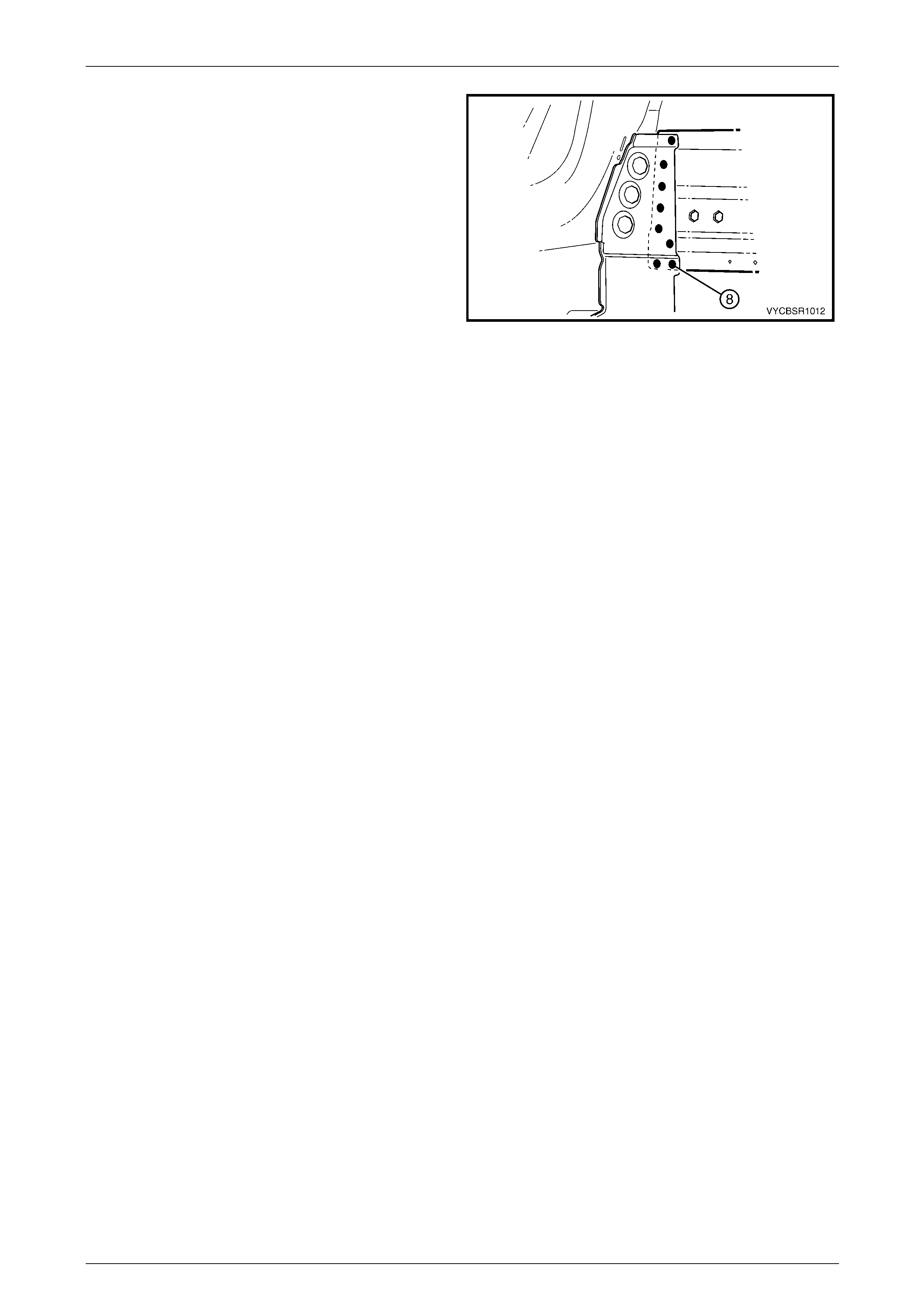
4 From inside the vehicle, spot cut the welds o n each
side of the vehicle, attaching the rear body upper i nner
panel to the side body inner p anel assembly.
NOTE
Some of these welds may have already been
removed with the rear body upper outer panel
assembly.
5 Remove the rear inner panel from the vehicle and
repair any damage to adjacent parts as required.
Figure 10E – 14
Replace
NOTE
• Spot welding is the preferred method for
attaching of panels and should be used
whenever possible. Where the spot welding
equipment available will not access the
required weld position, a plug weld should be
performed.
• The same number and position of spot welds
(or plug welds) should be used when
replacing the panel, as was used during
manufacture, in order to maintain the original
structural strength of the vehicle.
1 As required, mark the new panel with drilling locations in preparation for plug welding. Drill holes as required.
2 Prepare all mating surfaces and treat with Weld Through Primer (Item 1) as requir ed,
refer to Section 3E Body Construction – Regular Cab.
3 Clamp the rear body upper i nner panel in position on the ve hicle.
10E Body Rear – Regular Cab Page 10E–10
Page 10E–10
4 From inside the vehicle, spot or plug weld on each
side of the vehicle, the rear body upper inner panel to
the side body inner panel assembly.
5 Clean up the welds and a pply primer to any bare
metal.
6 Install the rear body upper outer reinforcement panel,
refer to 2.2 Rear Body Upper Outer Panel Assembly –
Replace.
7 Install the rear end lower panel, refer to
2.1 Rear Body Lower Panel – Repl ace.
8 Refinish and paint panels and other components as
required. Refer to Section 3 Body Construction . Figure 10E – 15
9 Apply Joint Sealer (Item 3) as required. Refer to Section 3E Body Construction – Regular Cab.
10 Apply Cavity Wax (Item 8) as required to the inside of any box secti ons or areas inaccessible to paint,
refer to Section 3E Body Construction – Regular Cab.
11 Install the remaining components as described in the appropriate Section of the MY 2005 VZ Service Information.