
3 Body Construction Page 3–1
Page 3–1
Section 3
Body Construction
ATTENTION
Before performing any service operation or other procedure described in this Section, refer to Section 2
Precautions in this Supplement and Section 00 Warnings, Cautions and Notes in the MY2005 WL Service
Information for correct workshop practices with regard to safety and/or property damage.
The structure of the body shell has been
developed using complex design and
development techniques. In addition to
meeting all required standards, the vehicle
body is also a critical part of the overall safety
systems. It is therefore imperative the repair
procedures described here are adhered to
during all vehicle body repairs.
1 General Information ...............................................................................................................................3
1.1 Body Structure Part Refinishing........................................................................................................................... 3
1.2 Anti-Corrosive Treatment...................................................................................................................................... 4
1.3 Paint Refinishing.................................................................................................................................................... 5
Panel Refinishing................................................................................................................................................... 5
Paint Code.............................................................................................................................................................. 5
2 Body Structure Panels...........................................................................................................................6
2.1 Front End and Underbody..................................................................................................................................... 7
2.2 Upperbody Structure – Excluding Roof Structure.............................................................................................. 9
2.3 Roof Structure...................................................................................................................................................... 11
2.4 Body Structure..................................................................................................................................................... 12
3 Body Dimensions.................................................................................................................................14
3.1 Underbody Dimensions – Projected .................................................................................................................. 14
3.2 Upperbody Dimensions – Actual........................................................................................................................ 16
Front...................................................................................................................................................................... 16
Side and Interior................................................................................................................................................... 17
Rear....................................................................................................................................................................... 18
4 Body Margins........................................................................................................................................19
5 Body Sealing, Adhesives And Deadeners.........................................................................................22
5.1 Acrylic Spot Weld Sealer (Item 2)....................................................................................................................... 24
Acrylic Spot Weld Sealer (Item 2) Continued .................................................................................................... 25
5.2 Joint Sealer (Item 3)............................................................................................................................................. 26
Joint Sealer (Item 3) Continued.......................................................................................................................... 27
Joint Sealer (Item 3) Continued.......................................................................................................................... 28
Joint Sealer (Item 3) Continued.......................................................................................................................... 29
Joint Sealer (Item 3) Continued.......................................................................................................................... 30
Joint Sealer (Item 3) Continued and Hand Putty (Item 4) ................................................................................. 31

3 Body Construction Page 3–2
Page 3–2
5.3 Adhesive – Anti-Flutter (Item 5).......................................................................................................................... 32
Adhesive – Anti-Flutter (Item 5) Continued ....................................................................................................... 33
5.4 Adhesive – Structural (Item 6) ............................................................................................................................ 34
5.5 Spray-on Deadener.............................................................................................................................................. 35
5.6 Deadener Panels and Insulators......................................................................................................................... 36
5.7 Fusible Reinforcement Patches.......................................................................................................................... 38
Replace................................................................................................................................................................. 38
6 Cavity Wax ............................................................................................................................................39
Cavity Wax Equivalents.................................................................................................................................... 39
7 Bumper Impact Bar Assemblies.........................................................................................................41
7.1 Front...................................................................................................................................................................... 41
Remove................................................................................................................................................................. 41
Reinstall................................................................................................................................................................ 41
7.2 Rear....................................................................................................................................................................... 42
Remove................................................................................................................................................................. 42
Reinstall................................................................................................................................................................ 42
8 Special Tools ........................................................................................................................................43

3 Body Construction Page 3–3
Page 3–3
1 General Information
This Section describes the body structure as a whole and provides a detailed breakdown of the body structure
components, key body dimension al measurements and body margin tolerances.
The various sealers and adhesives used throughout the body are also described, as it is imperative that only the correct
materials are used for repairs.
The correct cavity wax, deadeners a nd paint refinishing techniques are also imperative if the vehicle is to be returne d to
its original condition.
When replacing or repairin g a part or sub-assembly, care must be taken to ensure that correct alignment and strength of
unit as a whole is maintained. In some instances, major damage to the body or frame can be repaired more effectively
and economically by replacing a part or sub-assembly with a new one, rather than repairing the damaged part.
A sunroof option is available that is fitted on the production line. To cater for this option, a unique roof structure is fitted
which features a housing asse mbly in place of the roof bow panels. A stainless steel front drain tube is also fitted within
the hinge pillar cavity which effects the service procedures for the hinge pillar, refer to Section 7 Body Side and
Section 9 Roof.
1.1 Body Structure Part Refinishing
The vehicle body structure is designed to meet or exceed many regulations, including crash performance and occupant
protection, etc. When replacing or repairin g a part or sub-assembly, care must be taken to ensure that correct alignment
and strength of unit as a whole is maintained.
In some instances, major damage to the body structure can be repaired more effectively and economically by replacing a
part or sub-assembly with a new one, rather than repairing the damaged part.
Spot welding is used extensiv ely for joining panels or assemblies, however special adhesives are playing an ever
increasing role in the joini ng of body structure components, either on their own or together with spot welds. Where
repairs are performed, it is imperative that effective rust proofing techniques, as outlined in the following paragraphs, be
observed.
It is for these reasons that qualified persons with suitable tr aining and qualifications only perform the repair or
replacement of body structure compon ents.

3 Body Construction Page 3–4
Page 3–4
1.2 Anti-Corrosive Treatment
Precoated and galvanised steel is used extensively for various bo dy structure components for increased corrosion
protection. Body panels such as the engin e hoo d, door and rear compartment lids outer panels are precoated on the
inner surface of the metal to improve corrosion protection. Other body structure member s have complete double-sided
galvanised protection.
In addition, a rust preventative material (cavity wax) is sprayed after paint application to areas such as the interior
surfaces of doors, etc.
Any repair or replacement of panels, assemblies, etc. that disturb this anti-corrosive treatment must be resealed and
should be included as part of the repair or replacement operation.
Anti-corrosive compounds used for repairs should be light bodied materials designed to penetrate between metal-to-
metal surfaces such as pinch weld flanges and integral panel attaching points.
All bare metal surfaces must be treated with metal conditioner and primed. T hese operations need to be carried out pri or
to the application of sealers, waxes and sound deadeners. Attaching points of new replacement panels should be
resealed. The hemming flanges of replacement doors and rear compartment lids will require resealing.
Open joins that require bridging of the sealer to close a gap should b e sealed with a heavy-bodied caulking material.
When colour applicatio n is required to restore repaired area s to original appearance, con v entional refinishing
preparation, undercoat build-u p and colour application tech niques should be employed.
When deadeners are disturbed during damage repair, or a panel has bee n replaced, the deadener material must be
replaced with an equivalent material. The location and pattern for replacement material can be determined by observing
the original deadener application outlines.

3 Body Construction Page 3–5
Page 3–5
1.3 Paint Refinishing
Panel Refinishing
Metal service replacement parts (or assemblies) are painted with a black, high bake factor y primer. To ensure sound
adhesion of colour coats in service, the following refinish steps are necessary.
1 Clean part with a wax and grease removing solvent such as Prepsol.
2 Scuff-sand panel lightly with wet and dry number 400 paper and water. Avoid cut throughs. Re-clea n part, and then
apply sealer to entire part.
3 If the factory primer coat has been cut through, apply metal conditioner to the exposed bare metal. Follow the
directions on container label.
4 Apply primer-surfacer to the entire part; allow to dry thoroughly before sanding.
5 Sand primer-surfacer using wet and dry number 400 pa per and water. Do not sand seale r .
6 Re-clean part.
7 Apply colour coats to parts as directed on the container label.
8 Follow directions on cont ainer label for drying time before compounding.
9 Compound part by hand or with power equipment.
10 Non-sealing polish may be applied after rub-out if des ired. Waxes however, should not be applie d until the paint
finish has aged for at least two months. NOTE
Always follow the paint manufacturer’s
recommendations to ensure a high quality
durable finish is achieved.
Paint Code
The Paint Code for the vehicle can be found on the Body
and Option Identification Plate (1).
Figure SectNum – 1
The Paint Code enables a refinish paint to be matched with
the original paint colour. NOTE
The paint on the vehicle may not exactly match
the original colour due to fade, in which case
paint colour matching will be required. As this is
an acquired skill, it is a task that must be
performed by qualified individuals.
Figure SectNum – 2

3 Body Construction Page 3–6
Page 3–6
2 Body Structure Panels
The following tables and illustrations describe the body structure assemblies and panels that are available for service
replacement.
NOTE
Always refer to your authorised Retail er for spare
parts availability configurations.
3 Body Construction Page 3–7
Page 3–7
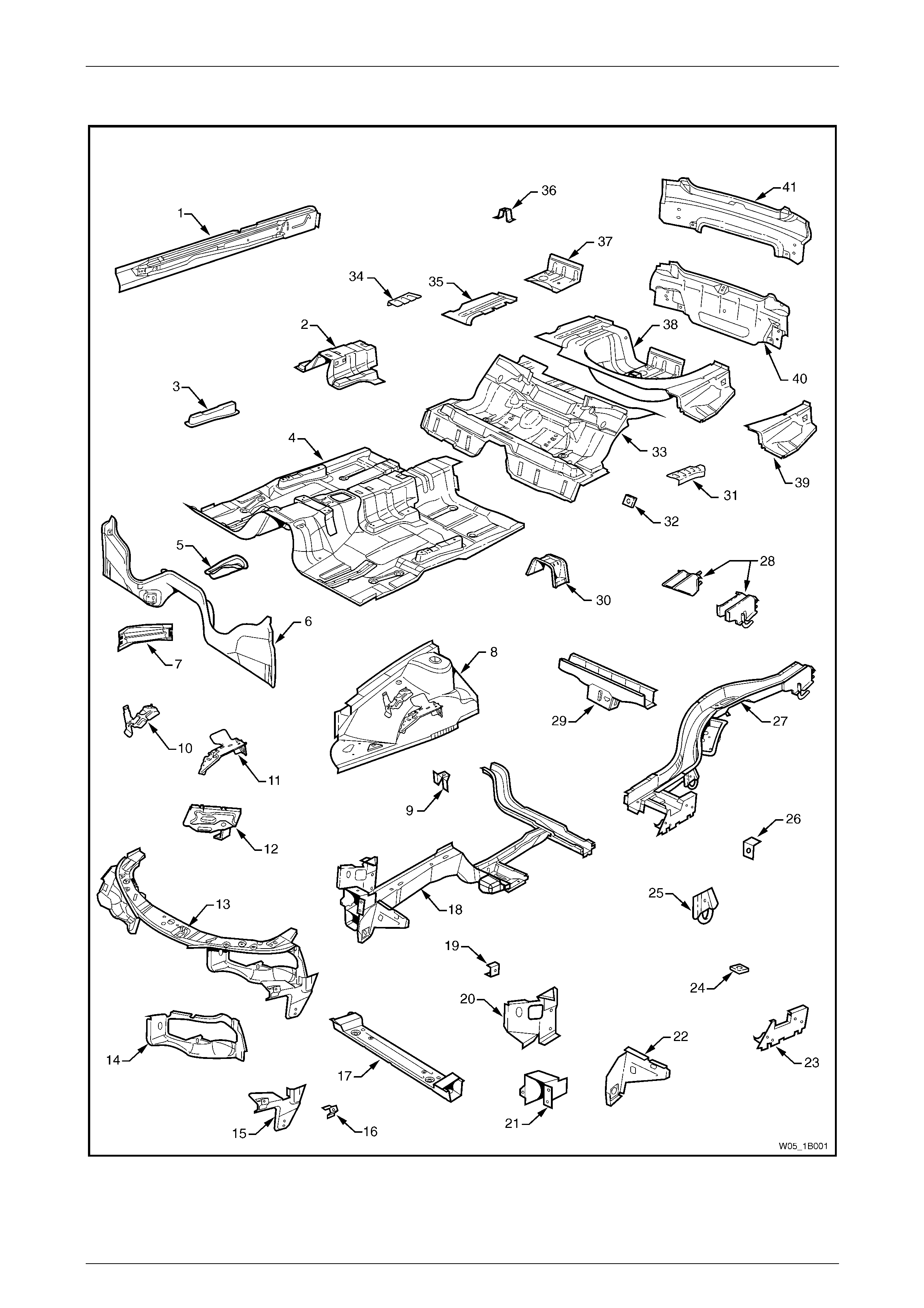
2.1 Front End and Underbody
Figure 3 – 3

3 Body Construction Page 3–8
Page 3–8
Legend
1 Inner Rocker Panel Assembly, Right-hand / Left-hand
2 Seat Inner Bracket Assembly
3 Seat Outer Bracket Assembly, Right-hand / Left-hand
4 Front Floor Panel Assembly
5 Transmission Support Bracket, Right-hand / Left-hand
6 Front Floor Panel Extension
7 Front Side Rail Brace, Right-hand / Left-hand
8 Front Wheelhouse Panel Assembly, Right-hand / Left-hand
9 Horn Bracket Assembly, Left-hand only
10 Relay Housing Bracket, Right-hand only
11 ABS Modulator Bracket Assembly, Right-hand only
12 Battery Tray Assembly, Right-hand only
13 Front End Panel Assembly
14 Headlamp Panel, Left-hand / Right-hand
15 Headlamp and Front Fascia Mount Bracket, Left-hand /
Right-hand
16 Fender Front Lower Bracket, Left-hand / Right-hand
17 Radiator Lower Support Assembly
18 Front Side Rail Assembly, Left-hand / Right-hand
19 Radiator Side Mounting Bracket, Left-hand / Right-hand
20 Front Wheelhouse Bracket Assembly, Left-hand / Right-
hand
21 Front Bumper Impact Bar Bracket, Left-hand / Right-hand
22 Front Wheelhouse Panel Bracket, Left-hand / Right-hand
23 Rear Floor Panel Outer Extension , Left-hand / Right-hand
24 Rear Suspension Support Mount Plate, Left-hand / Right-
hand
25 Rear Tie Down Assembly, Left-hand / Right-hand
26 Rear Brake Hose Bracket, Left-hand / Right-hand
27 Rear Side Rail Assembly, Left-hand / Right-hand
28 Rear Bumper Impact Bar Brace Assembly, Left-hand / Right-
hand
29 Crossmember Assembly No. 2
30 Propeller Shaft Hanger Assembly
31 Rear Floor Panel Reinforcement, Left-hand
32 Rear Seat Belt Anchor Plate Assembly, three places
33 Rear Floor Panel Assembly
34 Rear Floor Panel Reinforcement, Right-hand
35 Rear Compartment Floor Panel Outer Extension, Right-hand
36 Spare Wheel Anchor Plate Assembly
37 Fuel Tank Support Reinforcement Assembly
38 Rear Compartment Floor Panel Assembly
39 Rear Compartment Floor Panel Outer Extension, Left-hand
40 Rear End Panel Assembly
41 Rear End Lower Panel
3 Body Construction Page 3–9
Page 3–9
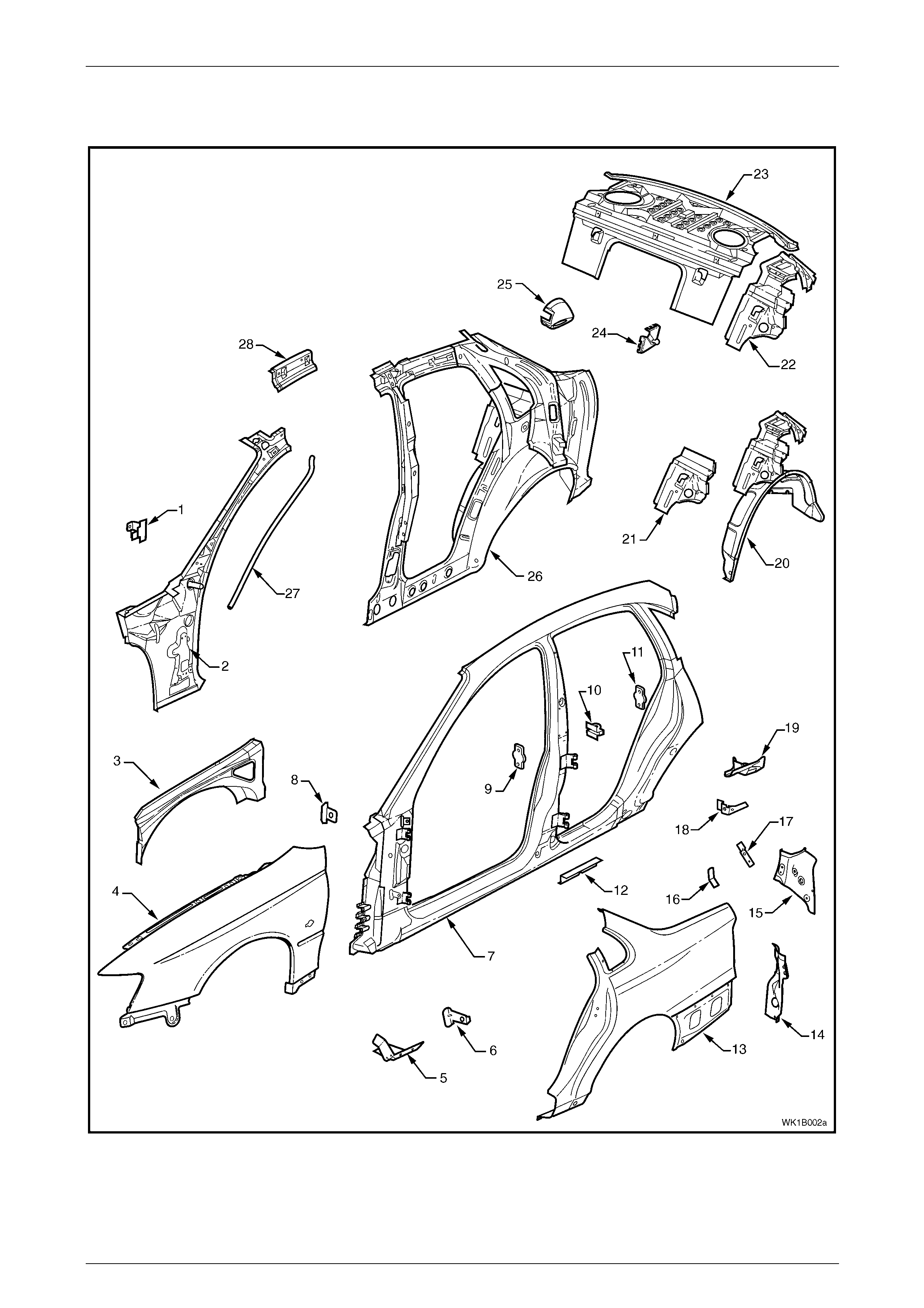
2.2 Upperbody Structure – Excluding Roof
Structure
Figure 3 – 4

3 Body Construction Page 3–10
Page 3–10
Legend
1 Hinge Pillar Trim Panel Bracket
2 Hinge Pillar Inner Panel Assembly
3 Front Wheelhouse Panel Upper Side Rail
4 Front Fender
5 Fender Lower Rear Bracket
6 Fender Rear Bracket
7 Door Opening Frame Assembly
8 Fender Upper Rear Bracket
9 Front Door Striker Anchor Plate
10 Rear Door Check Link Bracket
11 Rear Door Striker Anchor Plate
12 Underbody Jacking Locator
13 Rear Quarter Panel
14 Quarter Panel Lower Extension
15 Tail Lamp Housing
16 Wiring Harness Bracket
17 Tail Lamp Connector Bracket
18 Rear Compartment Trim Attach Bracket
19 Quarter Panel Upper Extension
20 Rear Wheelhouse Inner Panel Assembly
21 Rear Seat Back Panel Extension
22 Rear Seat Back Panel Extension Assembly
23 Rear Window Panel Assembly
24 Rear Compartment Lid Strut Bracket Assembly
25 Fuel Filler Pipe Housing
26 Quarter Panel Inner Assembly
27 Sunroof Front Drain Tube
28 Quarter Panel Inner Extension
3 Body Construction Page 3–11
Page 3–11
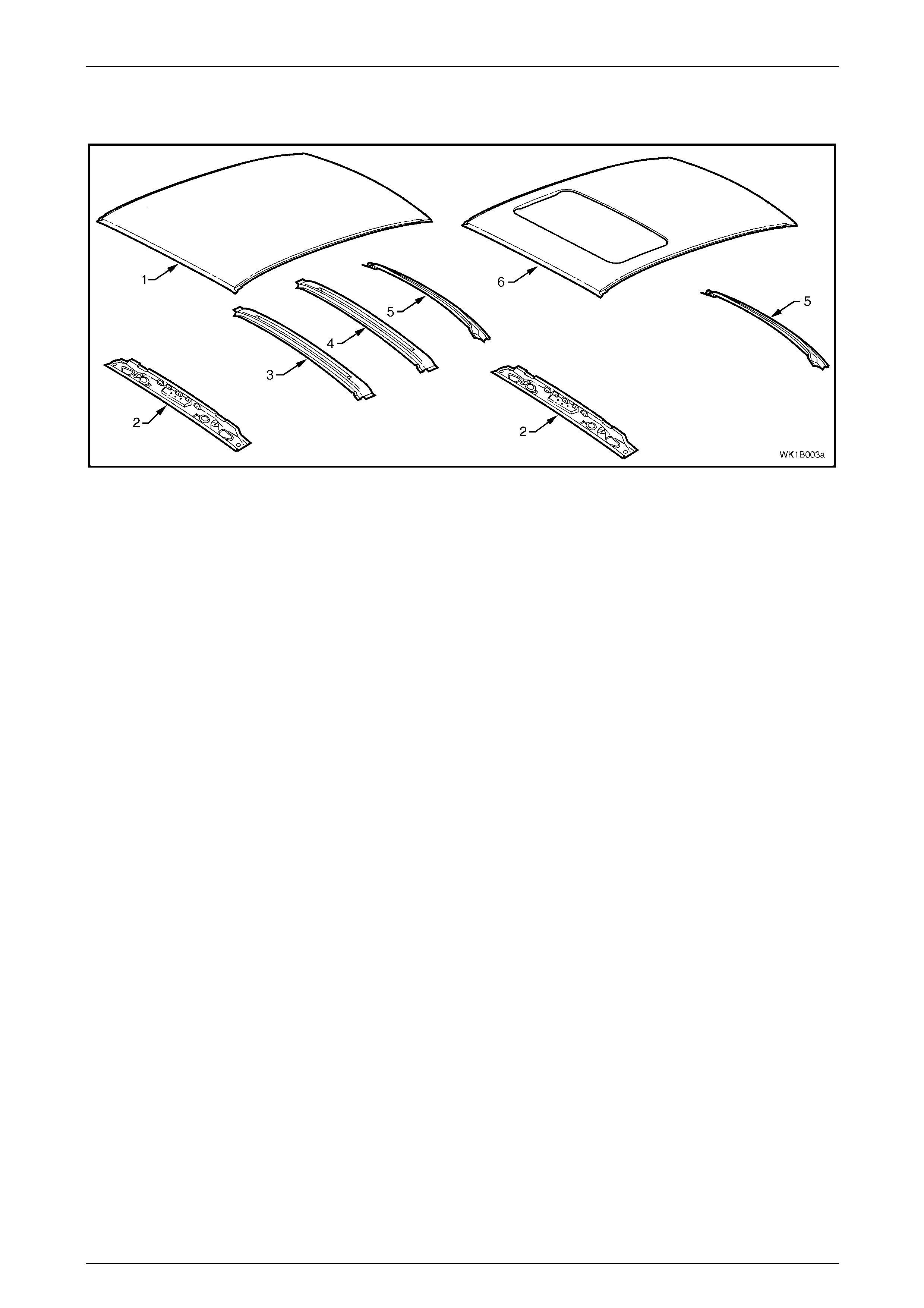
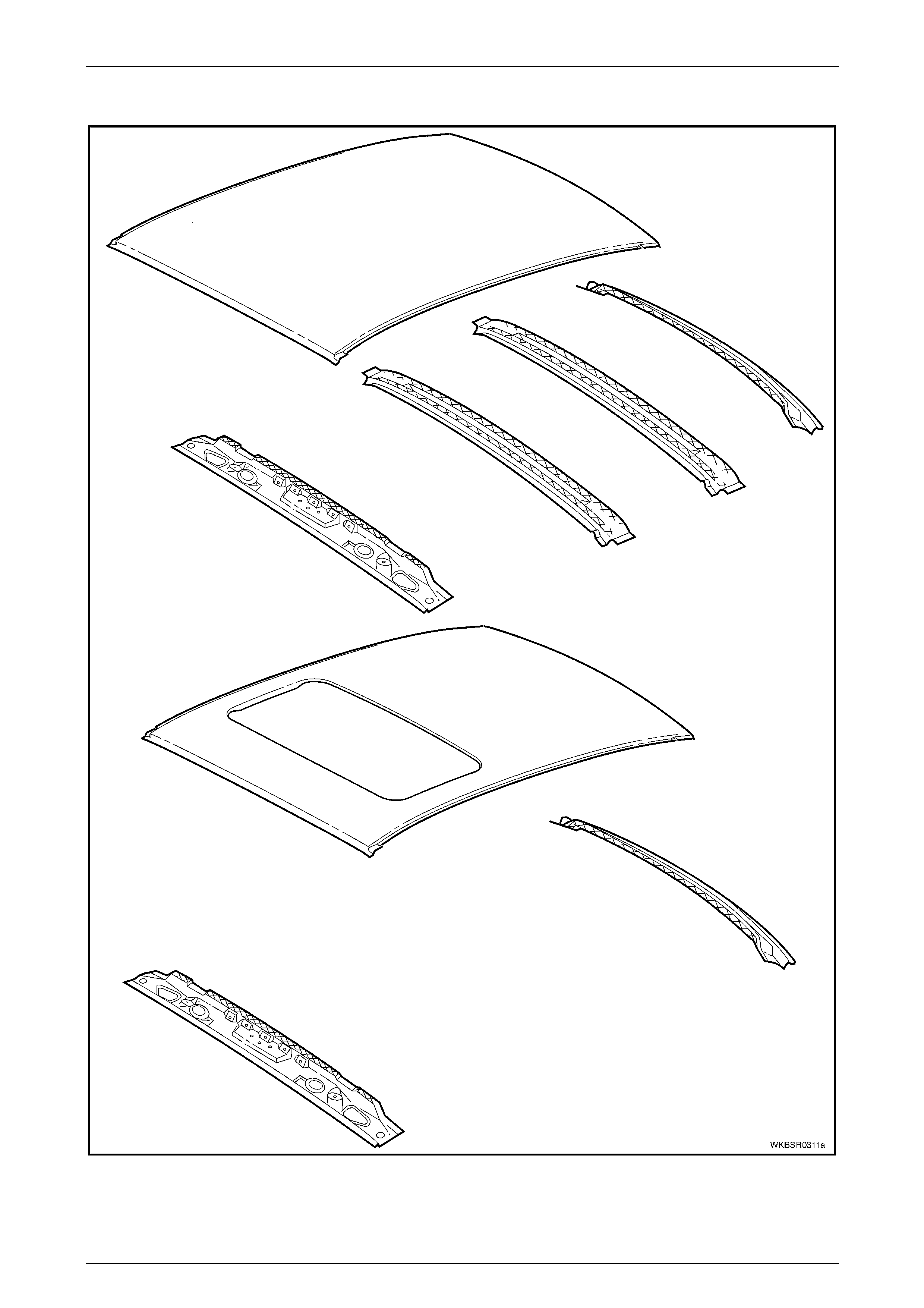
2.3 Roof Structure
Figure 3 – 5
Legend
1 Roof Panel
2 Roof Front Header Panel
3 Roof Bow Panel
4 Roof Bow Panel No. 2
5 Roof Rear Panel
6 Roof Panel Assembly (With Sunroof)

3 Body Construction Page 3–12
Page 3–12
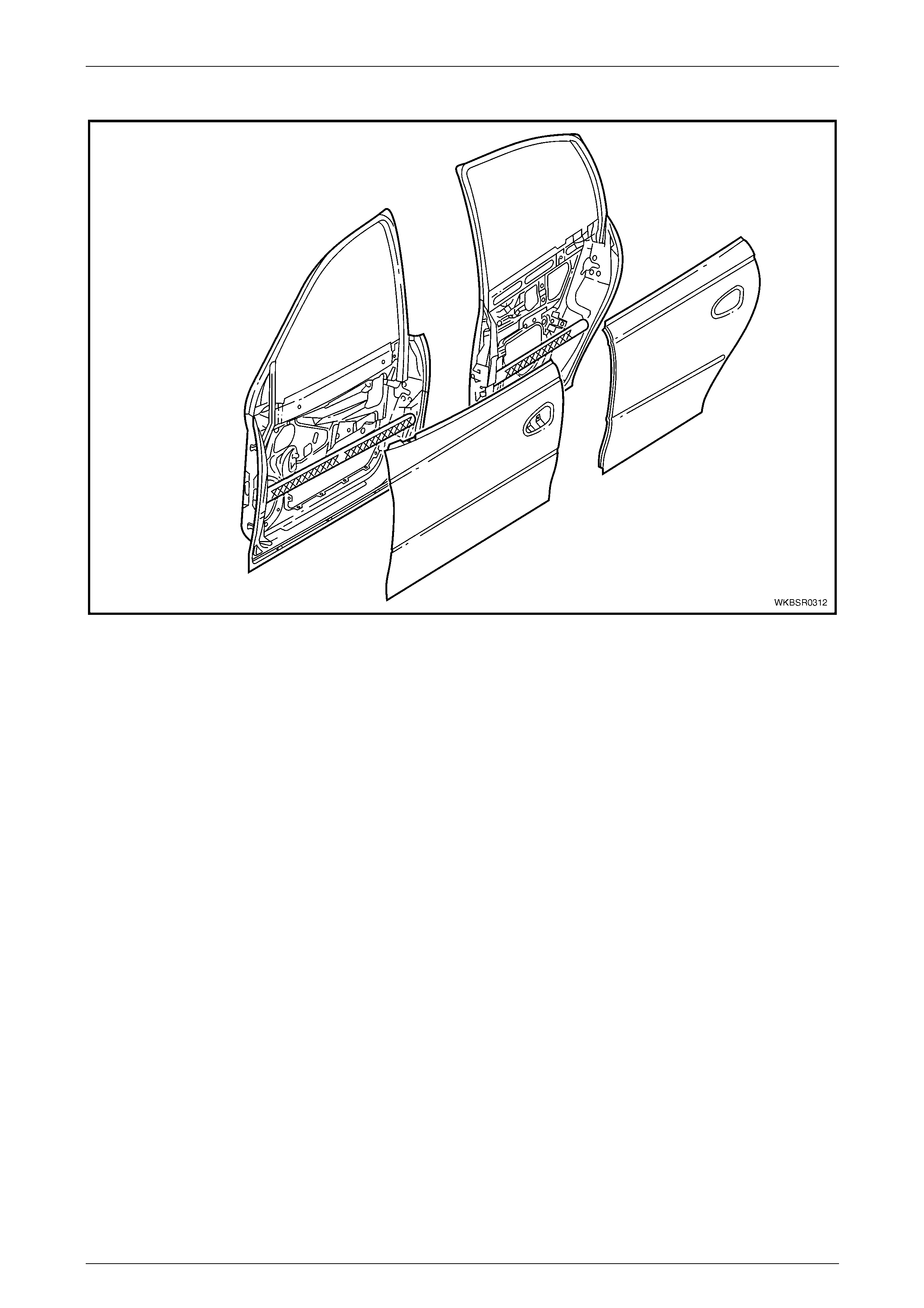
2.4 Body Structure
Figure 3 – 6

3 Body Construction Page 3–13
Page 3–13
Legend
1 Body Assembly
2 Dash Panel Assembly
3 Rear Compartment Lid Hinge Assembly
4 Rear Compartment Lid Assembly
5 Rear Bumper Impact Bar
6 Rear Bumper Impact Bar Bracket Assembly
7 Rear Door Assembly, Left-hand / Right-hand
8 Rear Door Outer Panel, Left-hand / Right-hand
9 Rear Door Hinge (door side), Left-hand / Right-hand
10 Rear Door Hinge (body side), Left-hand / Right-hand
11 Front Door Assembly, Left-hand / Right-hand
12 Front Door Hinge (body side), Left-hand / Right-hand
13 Front Door Hinge (door side), Left-hand / Right-hand
14 Front Door Outer Panel, Left-hand / Right-hand
15 Hood Hinge Assembly, Left-hand / Right-hand
16 Hood Assembly
17 Front Bumper Impact Bar Assembly
3 Body Construction Page 3–14
Page 3–14
3 Body Dimensions
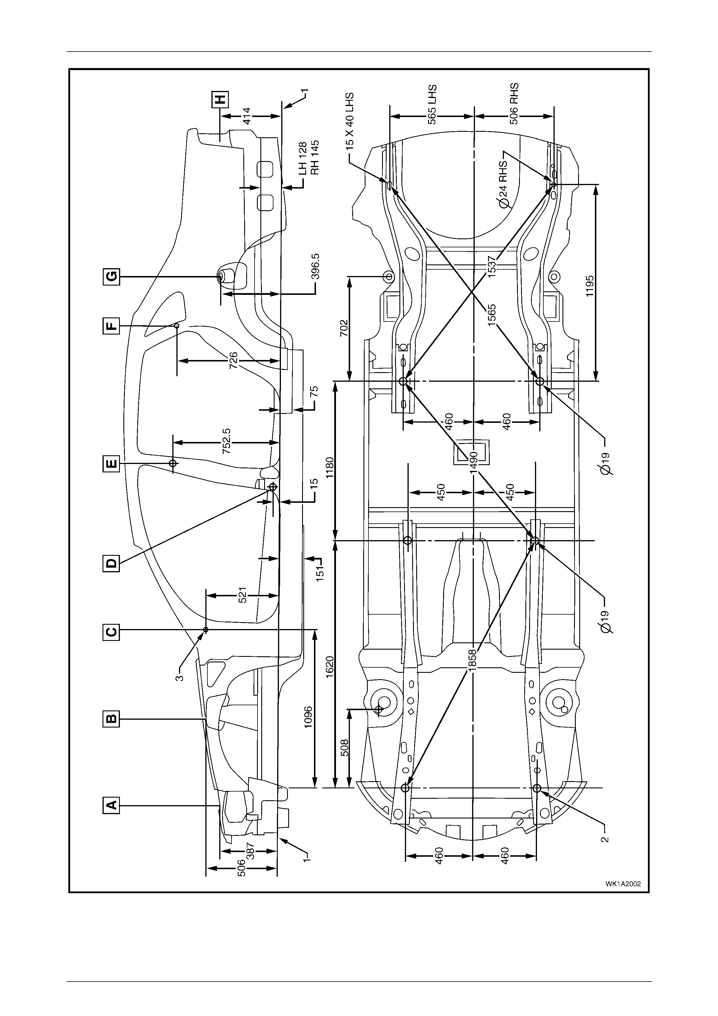
3.1 Underbody Dimensions – Projected
All dimensions are given in mm and are measured from the centre of holes, on the outer side of the metal surface.
The main datum surface (1) is the underside of the front side rail assembly, refer to Figure 3 – 8
The main datum hole (2) is a 19 mm hole on the underside of the front side rail assembly, refer to Figure 3 – 8.
The dash panel assembly attaching hole (3) in Figure 3 – 8 is the datum hole also depicted at View C in Figure 3 – 7.
Figure 3 – 7
3 Body Construction Page 3–15
Page 3–15
Figure 3 – 8
3 Body Construction Page 3–16
Page 3–16
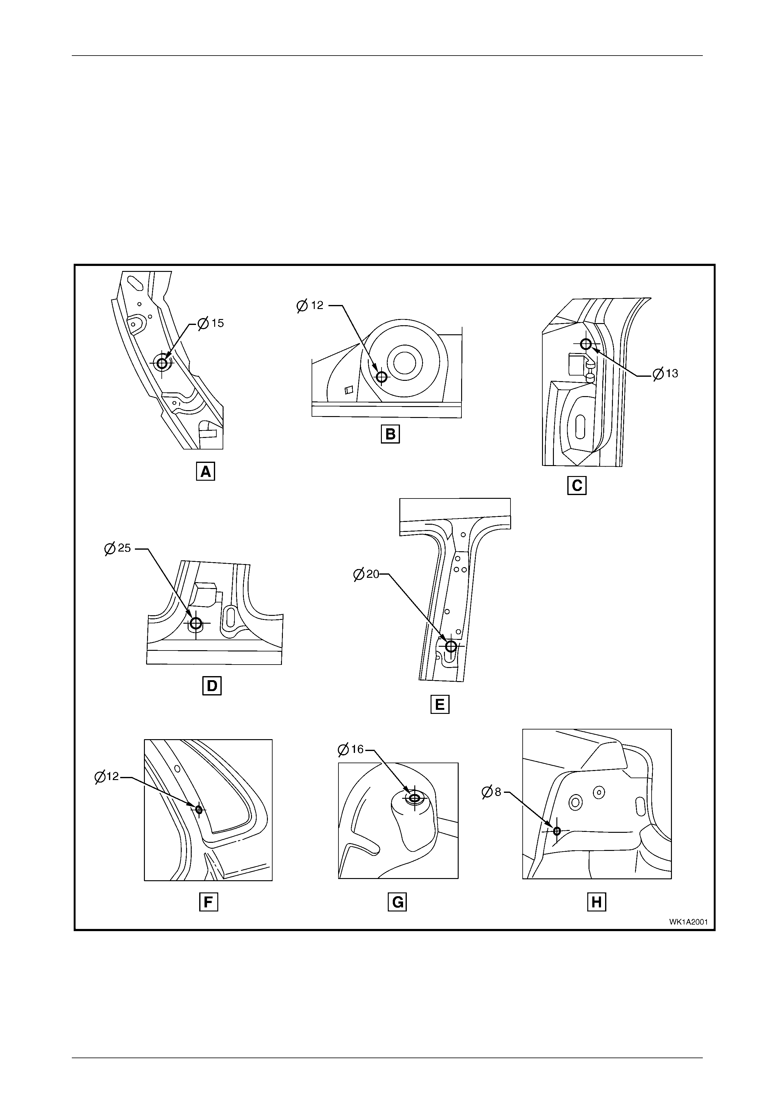
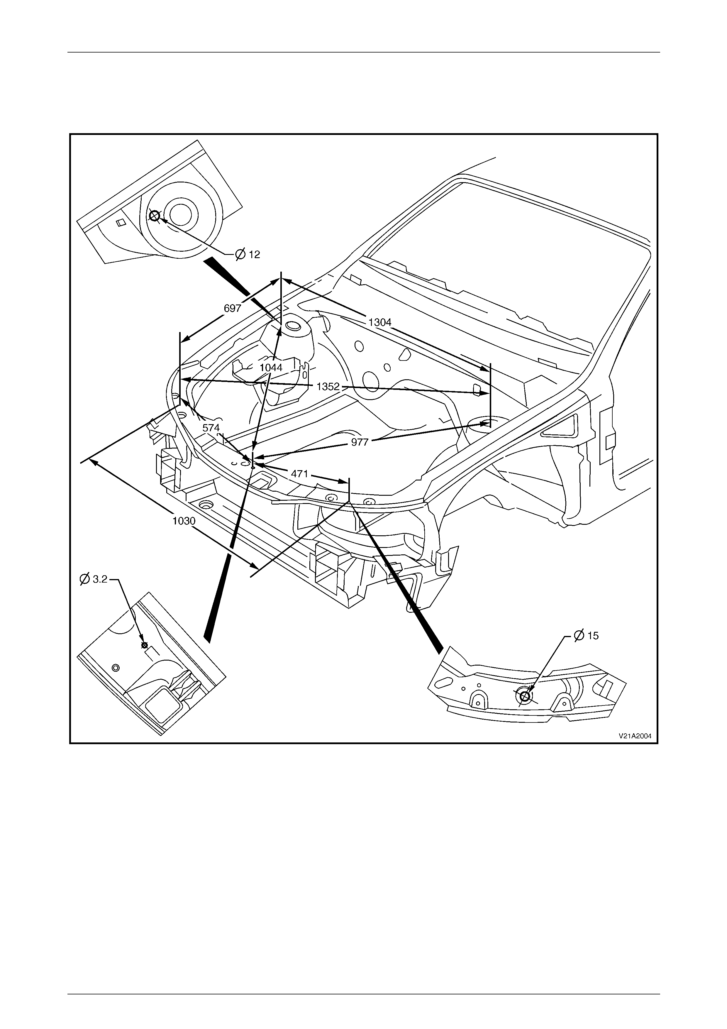
3.2 Upperbody Dimensions – Actual
Front
Figure 3 – 9
3 Body Construction Page 3–17
Page 3–17
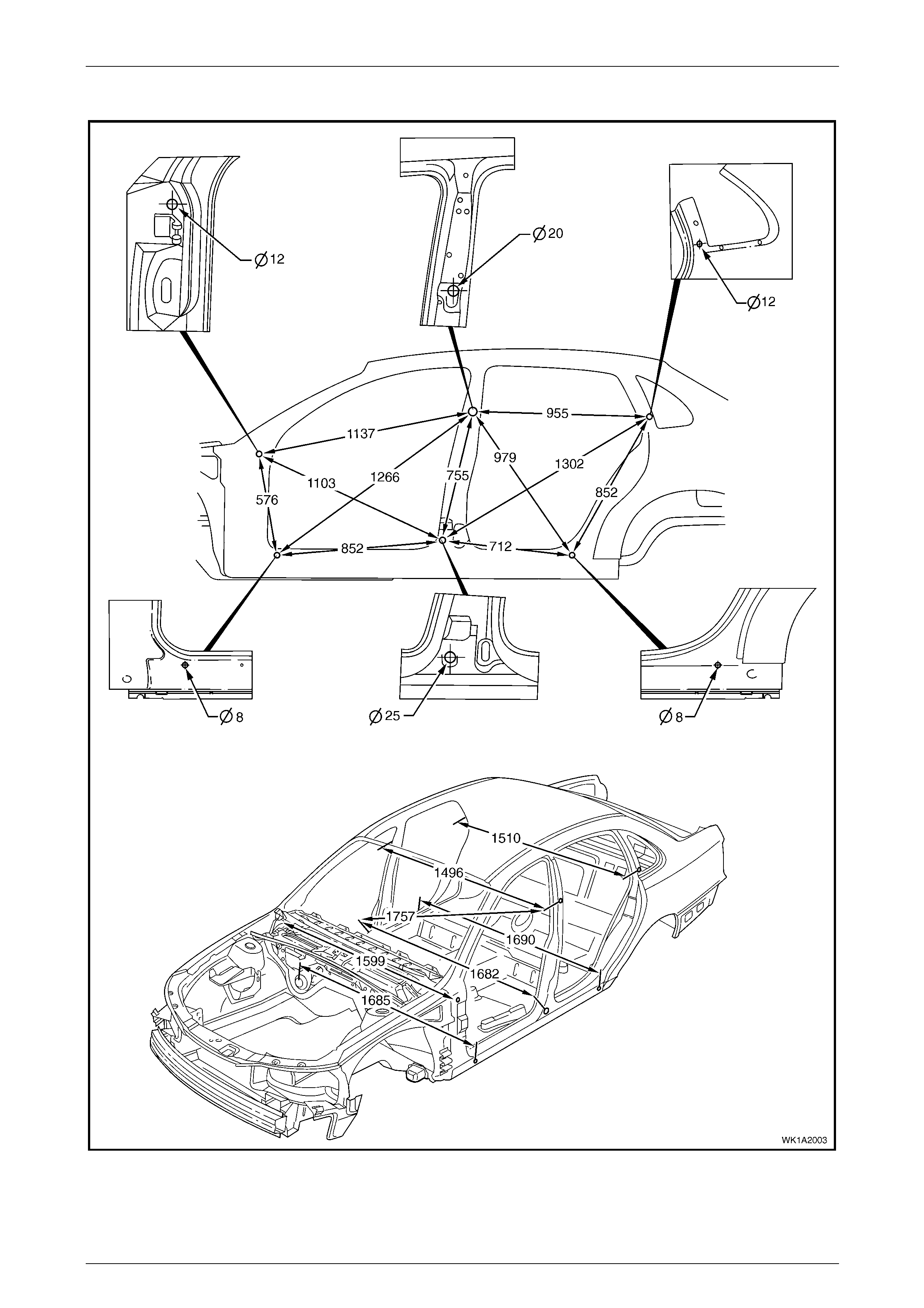
Side and Interior
Figure 3 – 10
3 Body Construction Page 3–18
Page 3–18
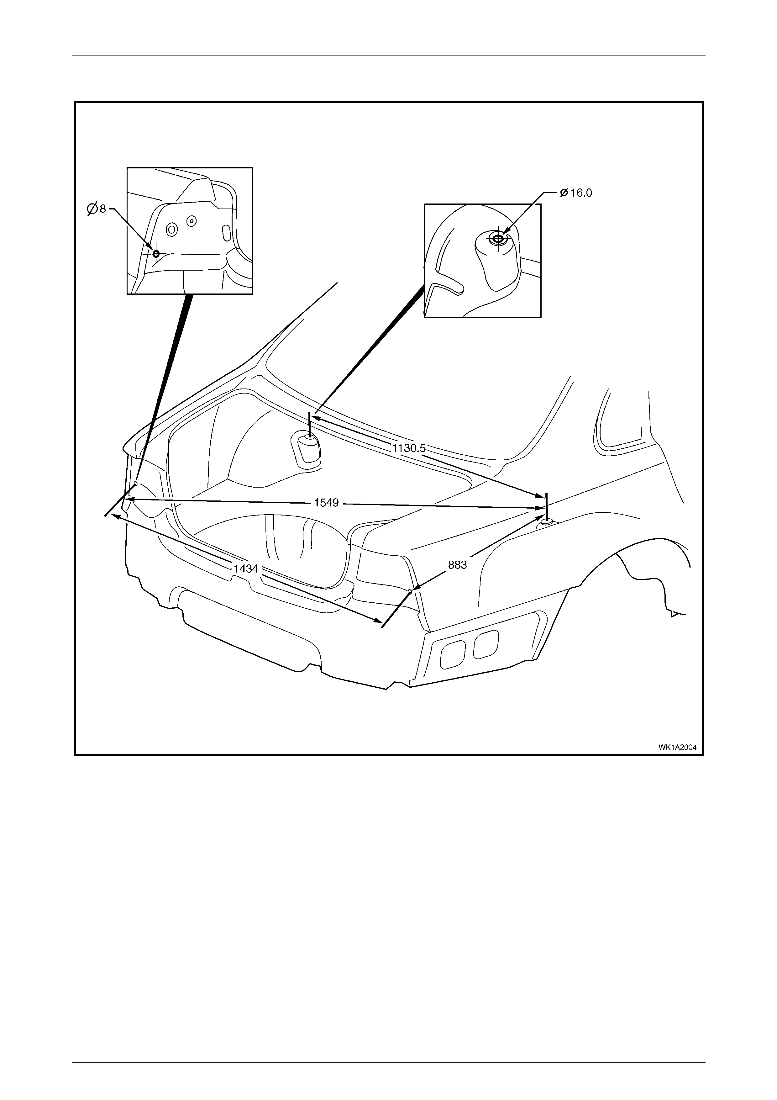
Rear
Figure 3 – 11
3 Body Construction Page 3–19
Page 3–19
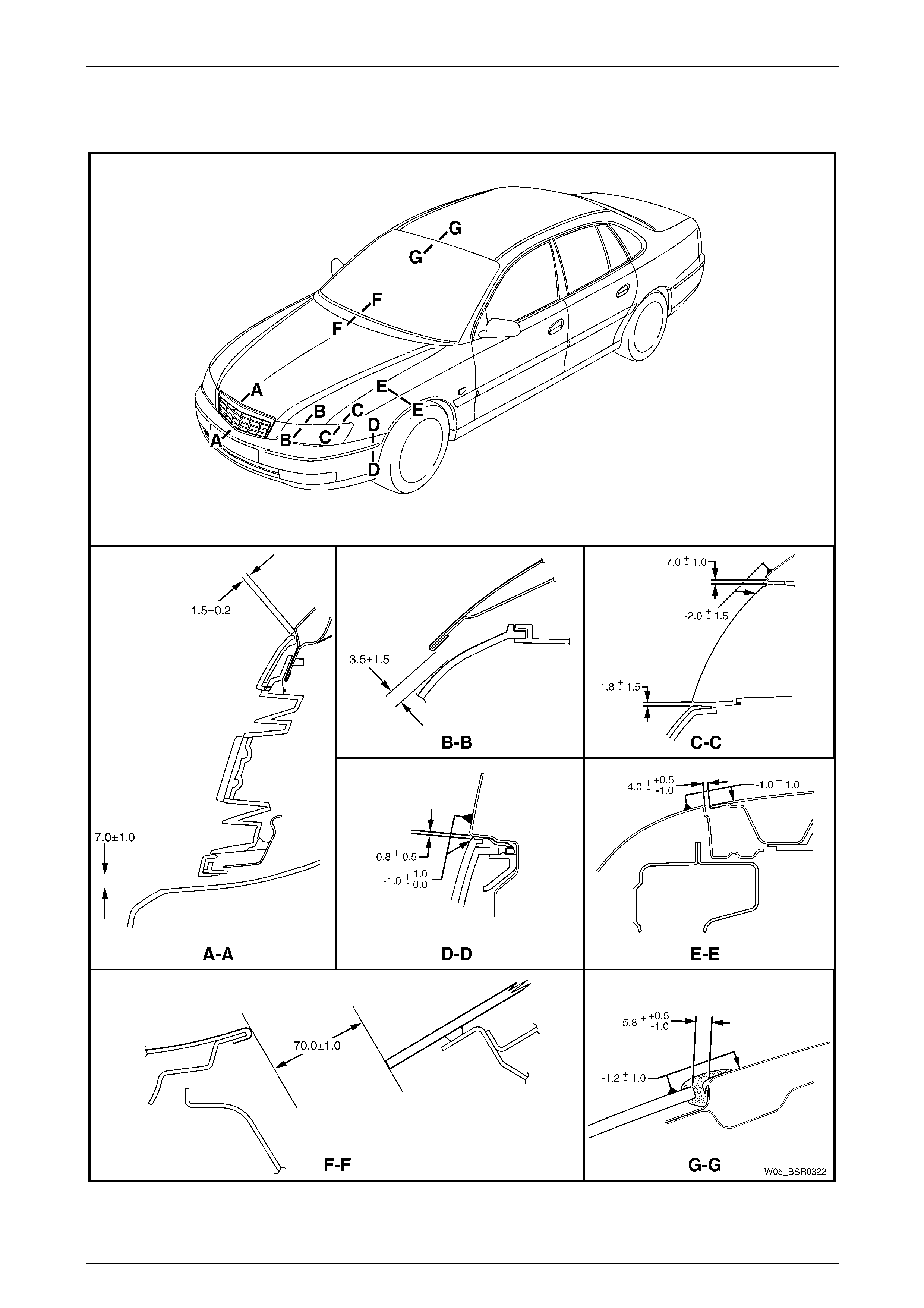
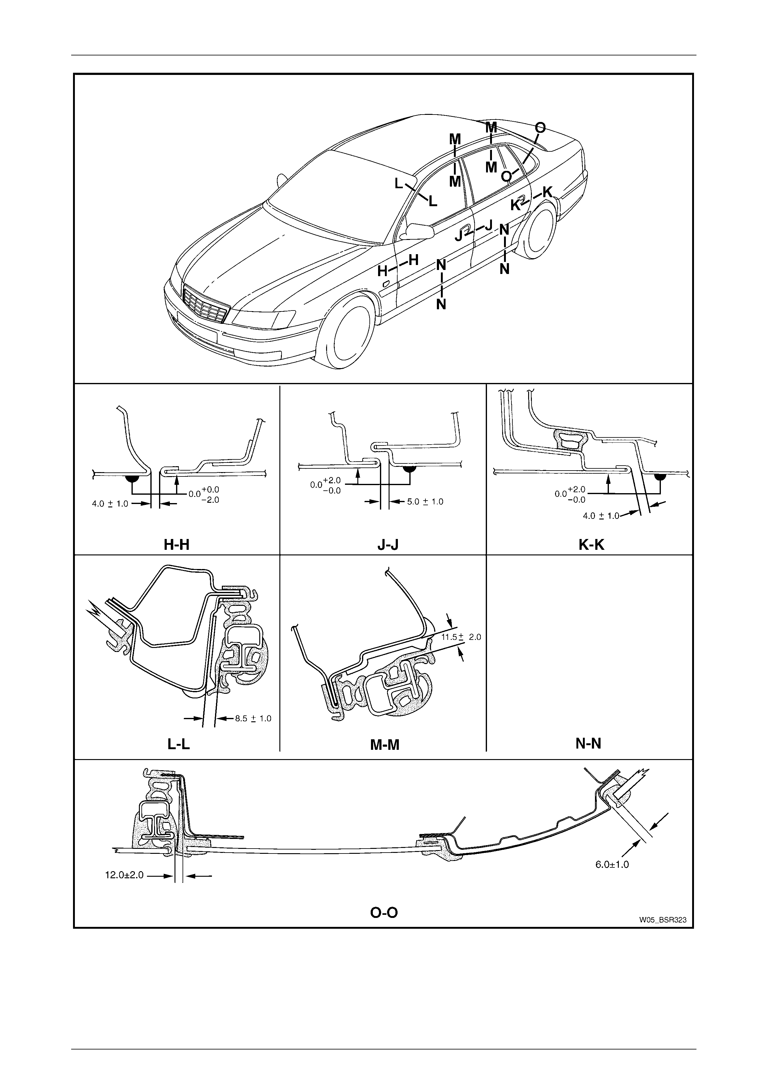
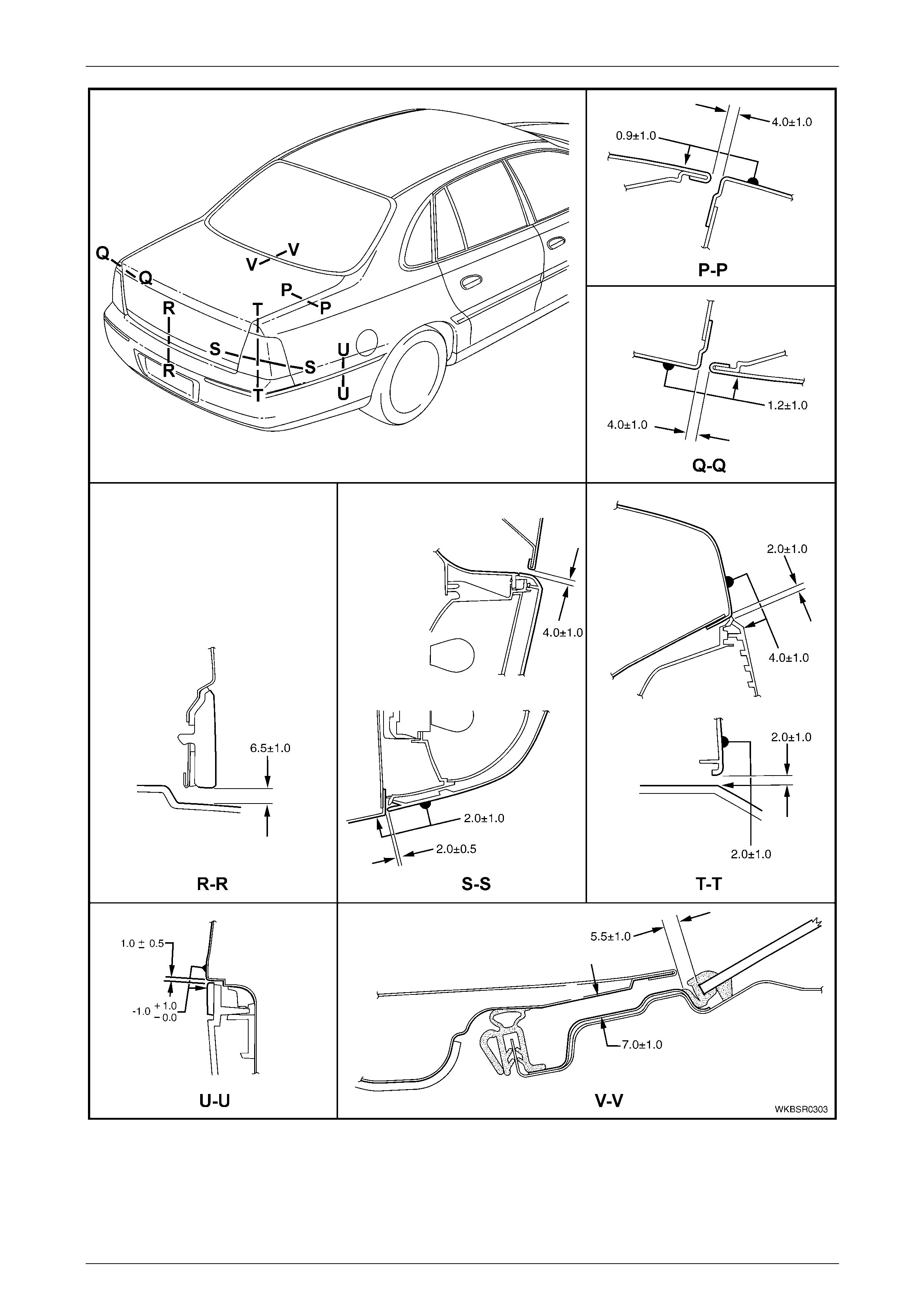
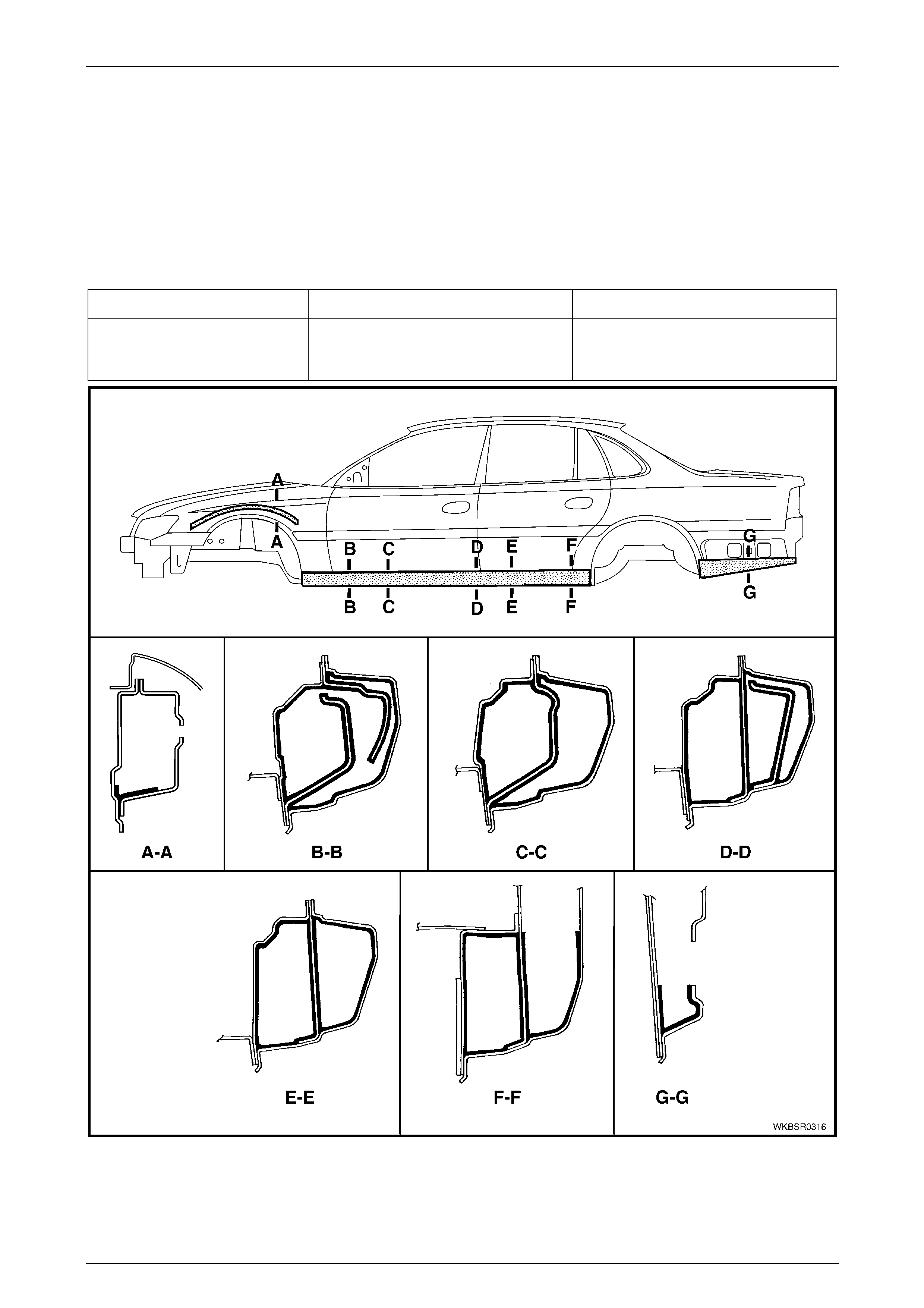
4 Body Margins
Figure 3 – 12
3 Body Construction Page 3–20
Page 3–20
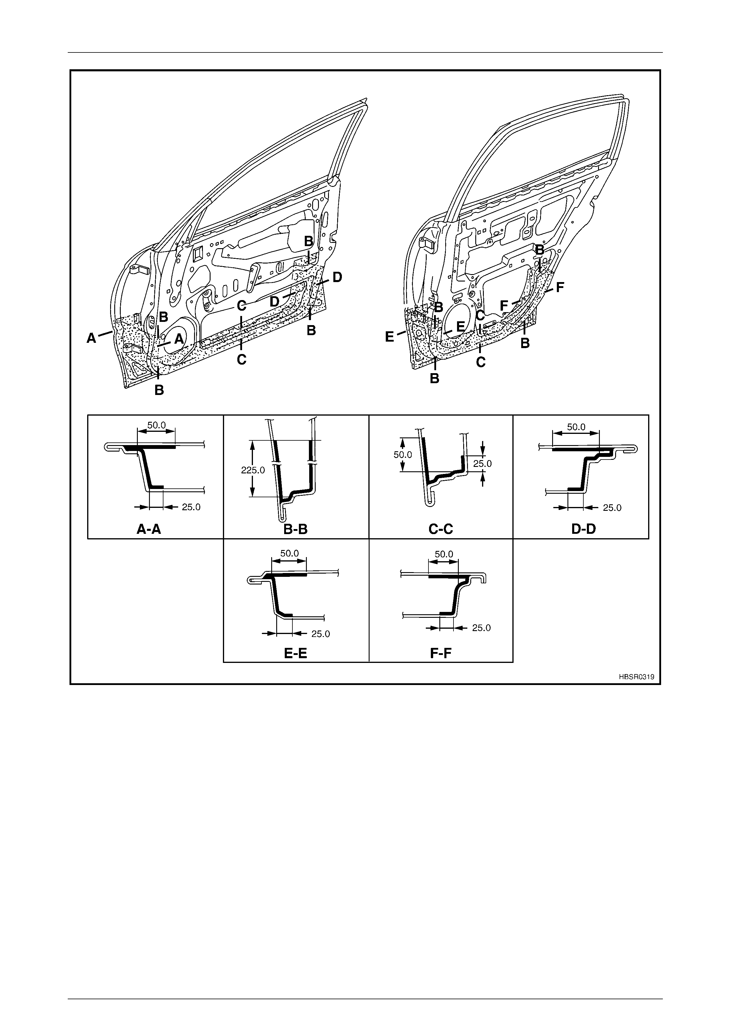
Figure 3 – 13
3 Body Construction Page 3–21
Page 3–21
Figure 3 – 14

3 Body Construction Page 3–22
Page 3–22
5 Body Sealing, Adhesives And
Deadeners
The commercially available products listed
below will meet the required standards. Other
products may be available that meet the
performance characteristics, however before
their use, the product manufacturer should be
contacted to check its suitability.
This Section details the sealers, adhesives and deadeners used i n the body shell. It is imperative that the correct
materials are used and the directions on the product always be followed.
NOTE
When replacing any sealer, adhesive or
deadener, ensure the finish meets that of the
original applica tion.
Weld Through Primer (Item 1)
Although not used in manufacture, Weld Through Primer is recommended for all service repa ir lap and flange joints
where Acrylic Spot Weld Sealer (Item 2) is not used. Weld Through Primer aids in corrosion protection of the joint.
Acrylic Spot Weld Sealer (Item 2)
Used in joints that require sealing additional to Joint Sealer (Item 3). It is applied to the jo int flange prior to the mating of
panels. Refer to Figure 3 – 15 and Figure 3 – 16.
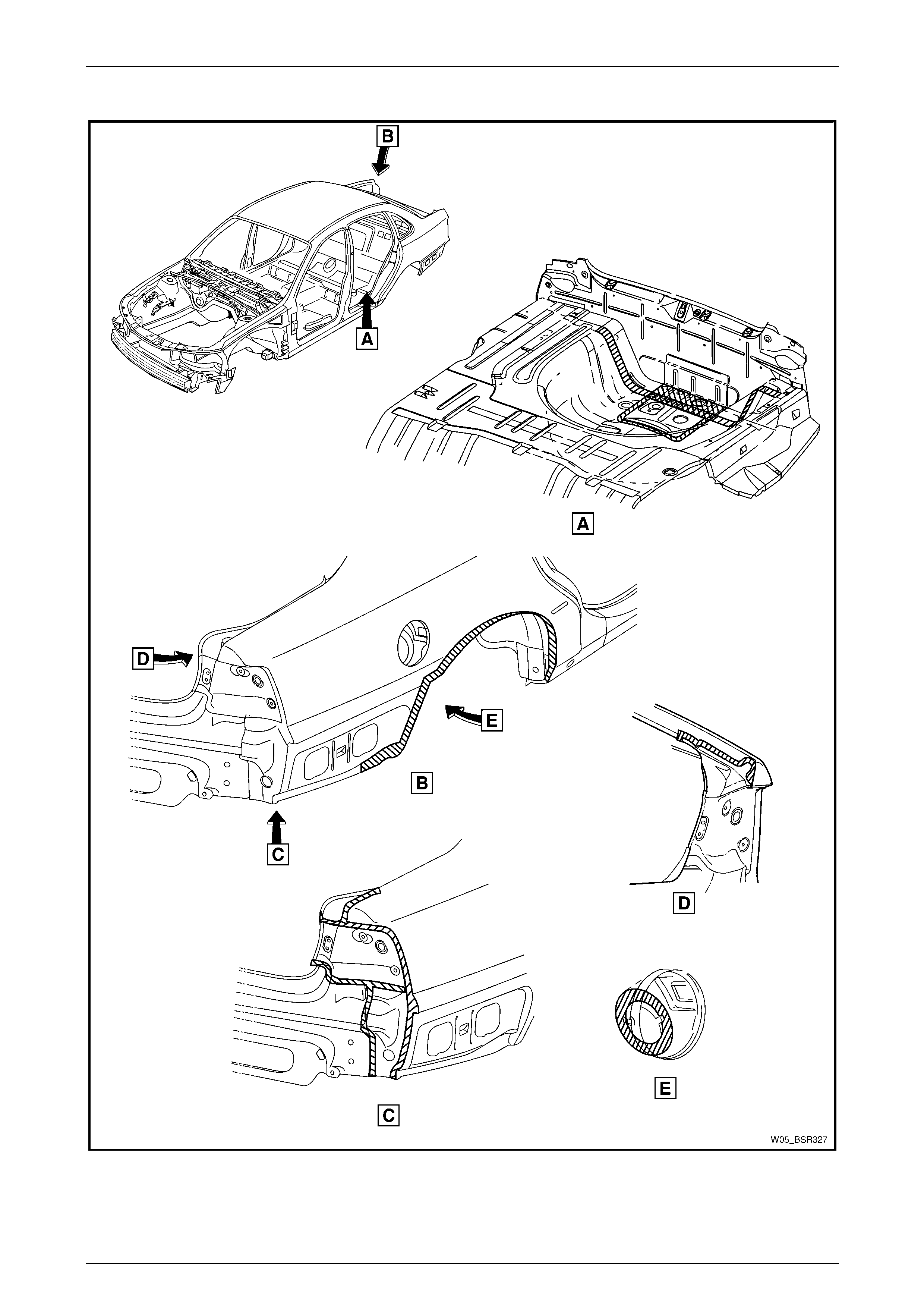
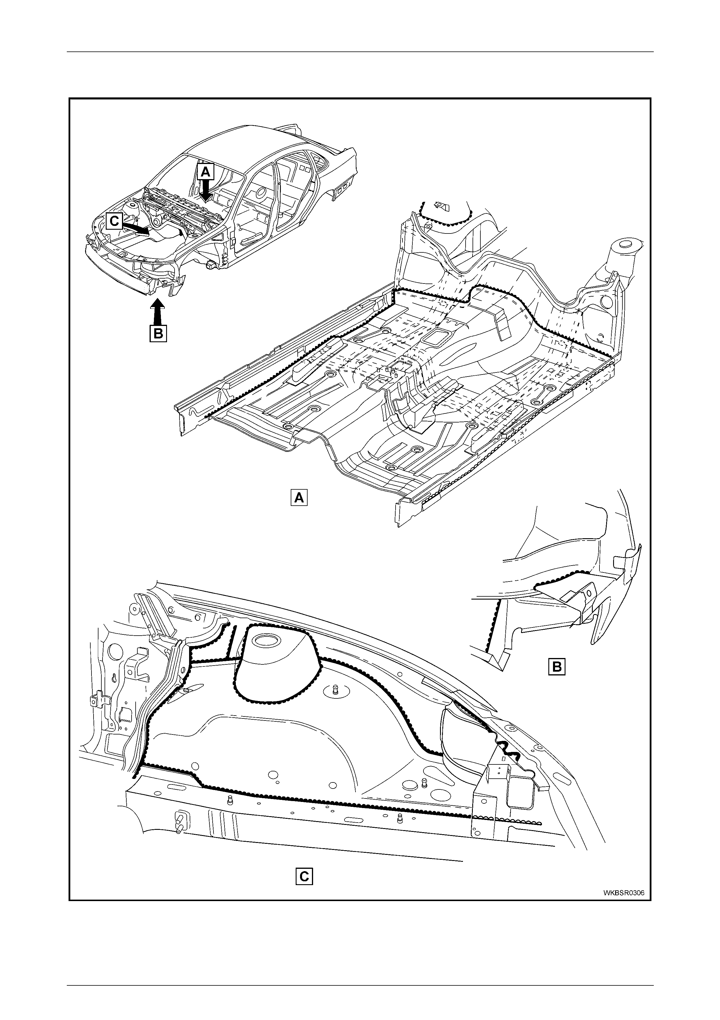
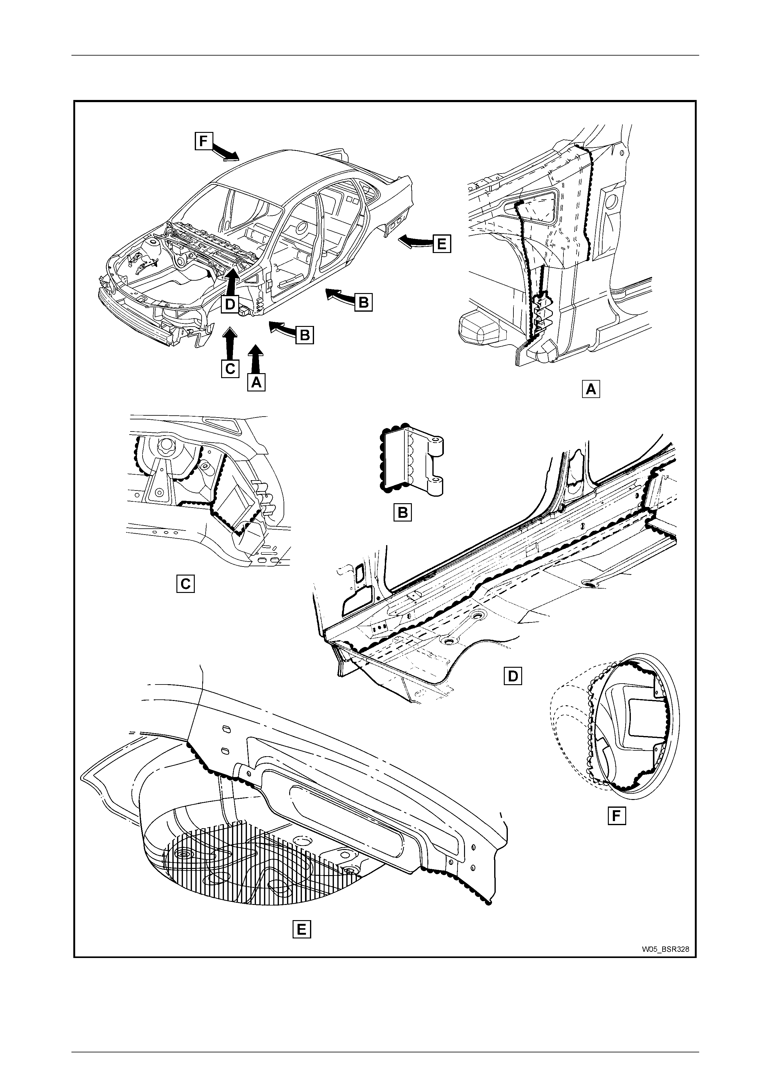
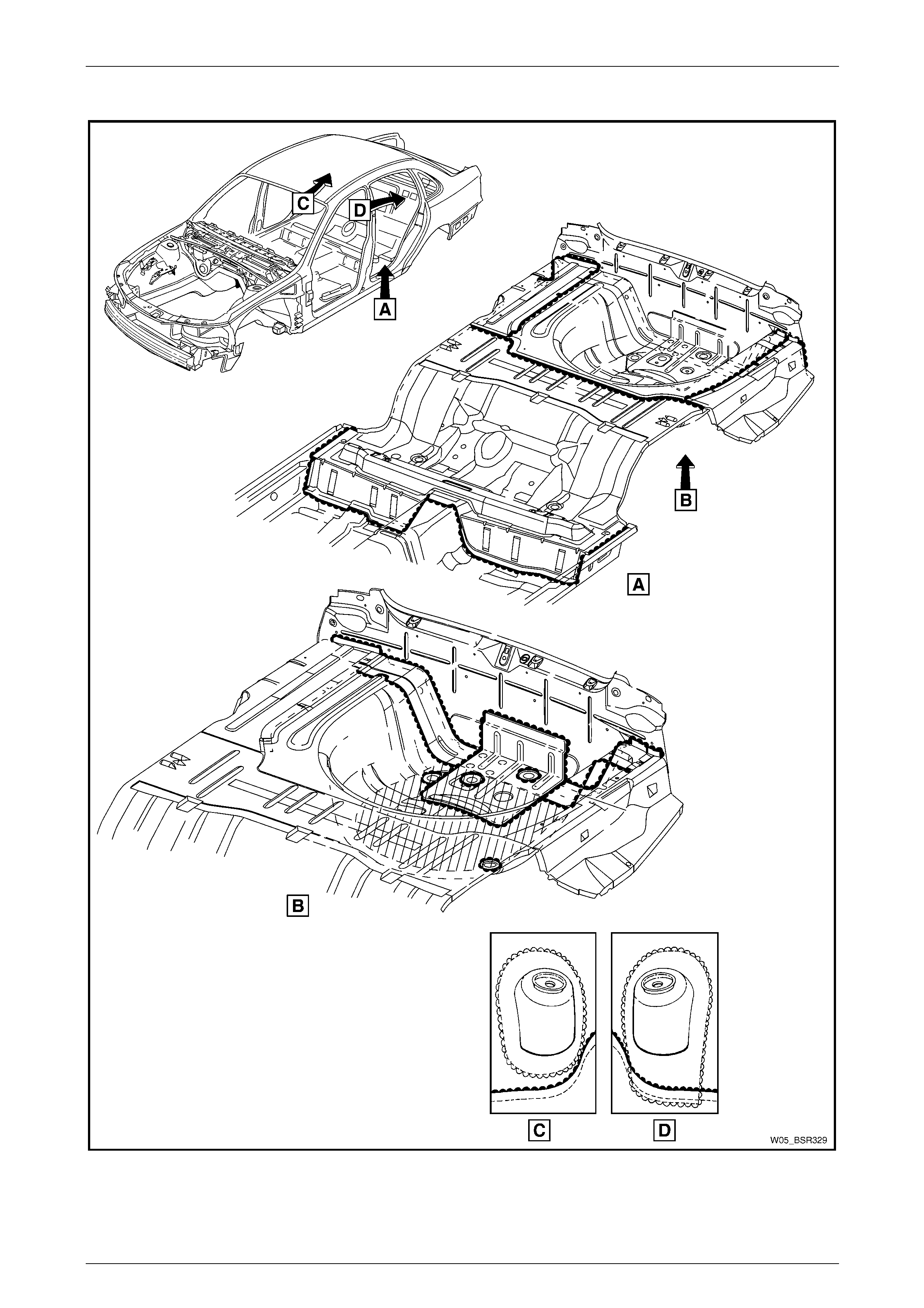
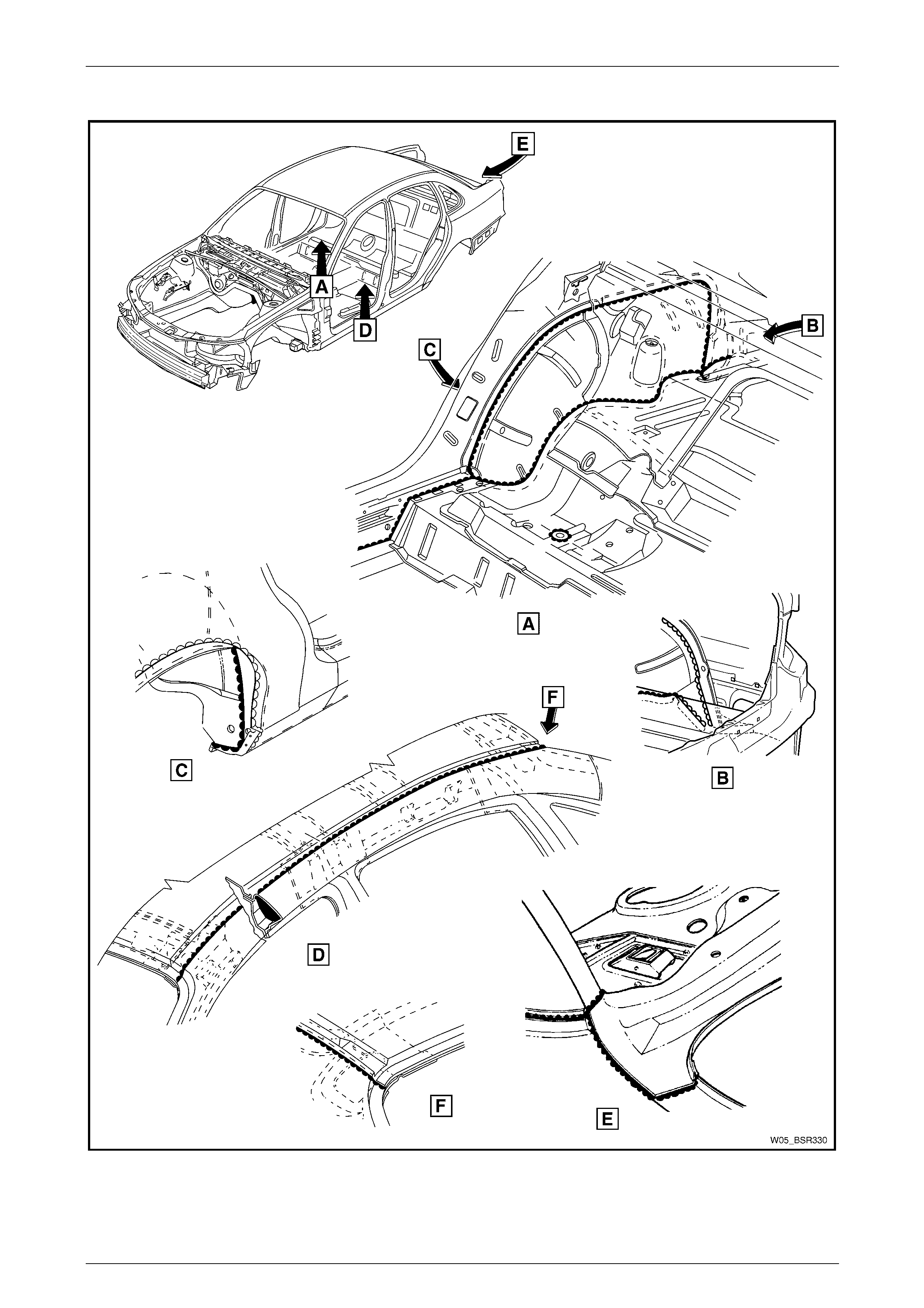
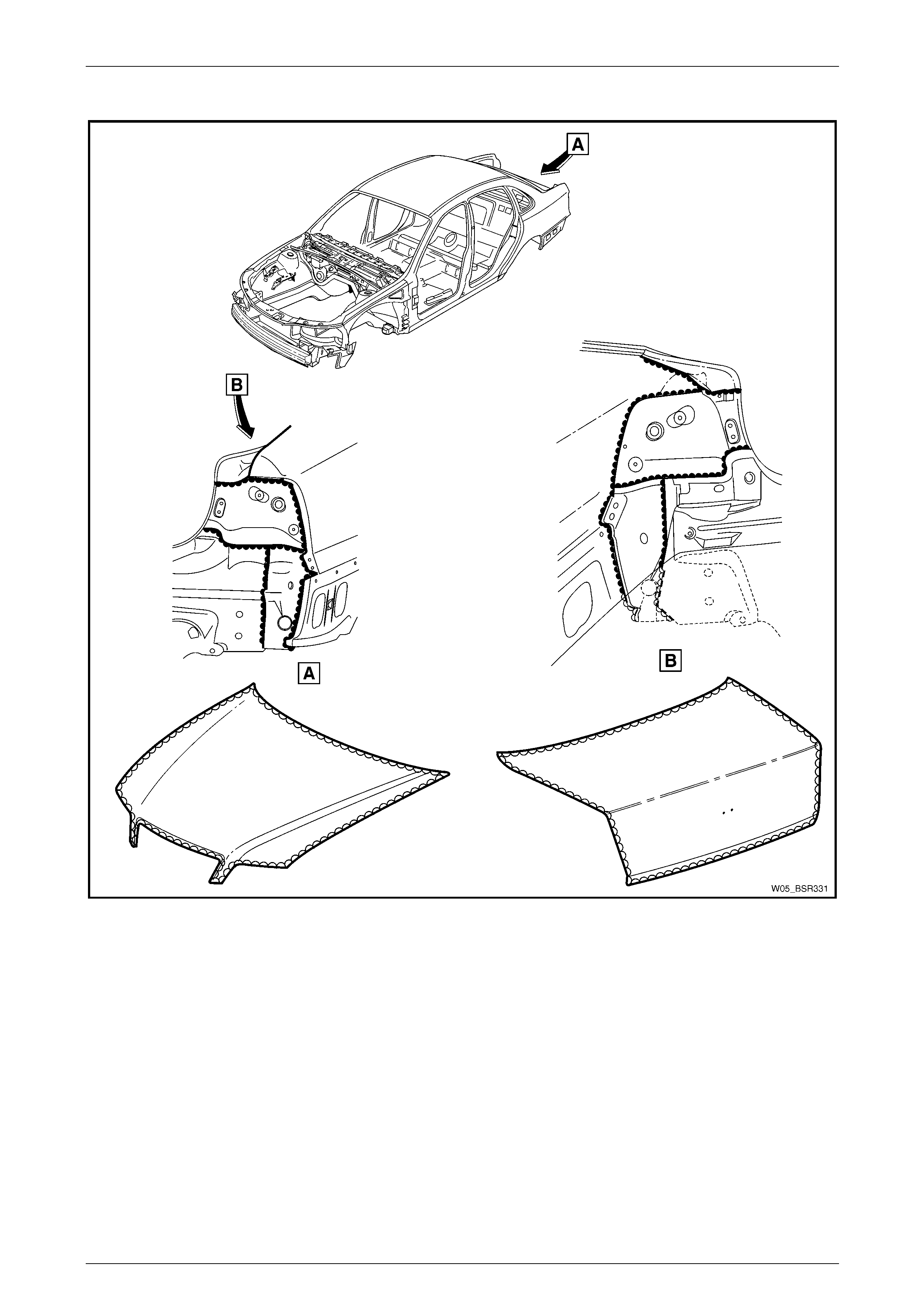
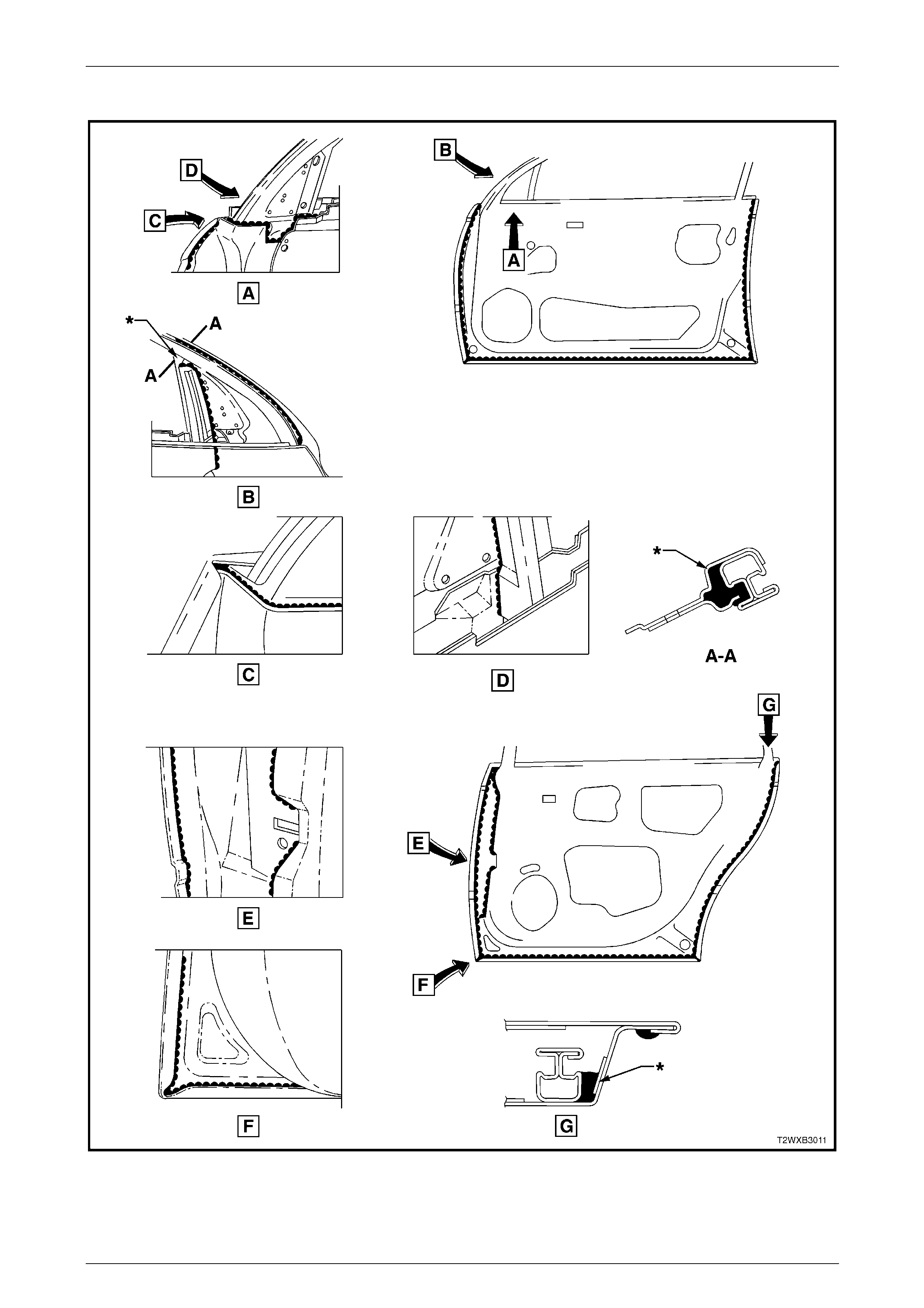
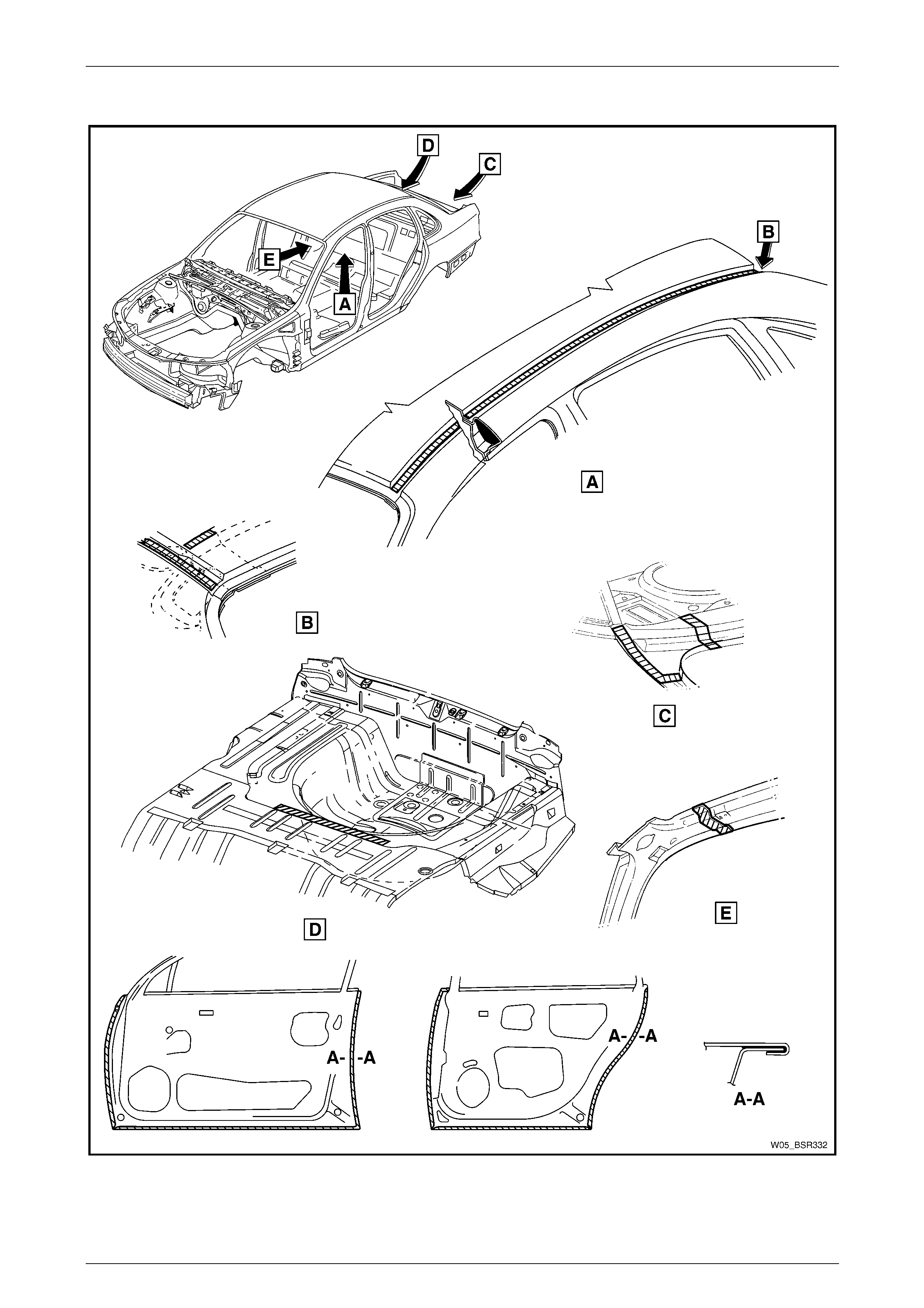
Joint Sealer (Item 3)
Primarily used for sealing joints to achieve a watertight seal. It seals notches, cut-outs and holes. Joint sealer sh ould be
applied after priming, prior to application of the top coat. Refer to Figure 3 – 17 – Figure 3 – 22.
NOTE
• Figure 3 – 18, View E illustrates the underside
of the spare wheel-well. Following priming,
this area is sprayed with sealer (rather than
deadener) to a minimum thickness of 2.5 mm
and has a rough finish. This procedure is
important due to the mou nting of the fuel tank
below it.
• During production a heat fusible patch is
applied along the joint of the back panel –
upper, refer Figure 3 – 20 View E. This patch
is not serviced as the heat required to fuse it
is beyond the capabil ities of the re pairer. Join t
sealer may be applied and finished to produce
a smooth surface.

3 Body Construction Page 3–23
Page 3–23
Hand Putty (Item 4)
Hand putty, also known as caulking compound, is used in the areas marked * in Figure 3 – 22.
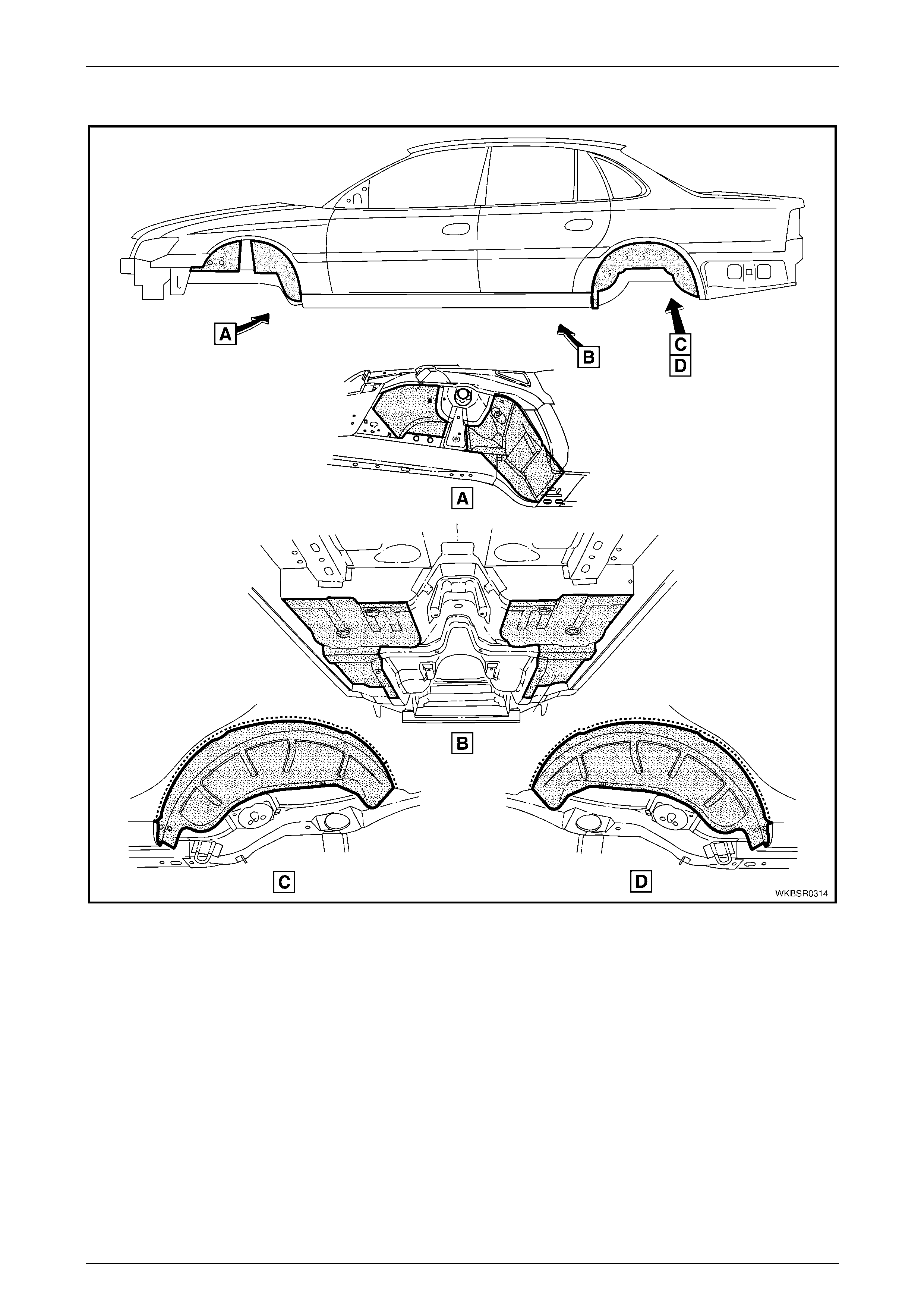
Adhesive – Anti-Flutter (Item 5)
While used as a filler between an inner and outer panel to reduce panel flex, Anti-Flutter adhesive also aids rigidity and
assists in dispersing loads over a larger area. Refer to Figure 3 – 23 and Figure 3 – 24 for locations.
Adhesive – Structural (Item 6)
Critical to the strength and rigidity of the vehicle, the correct adhesive must be used for service repairs. Using an
adhesive that is too weak will reduc e the performance of the joint. Using an adhesive that is too strong can also effect the
performance of the joint, compromising the vehicle’s crash performance and safety system’s operation. This adhesive is
a 2-part system. Refer to Figure 3 – 25 for locations.
Spray-on Deadener (Item 7)
This deadener is spra yed onto the body shell after painting. It is used in the wheel-wells and on the under side of the
floor pan. A minimum thickness of 1.5 mm is required in these app lications. Refer to Figure 3 – 26 for locations.
Deadener Panels
Deadener panels are sold pre-cut as service parts. They are installed with the coloured side up and diamond embossed
side down. The panels are installed prior to painting and some are heat fused to the bod y shell. Refer to Figure 3 – 27 –
Figure 3 – 30 for locations.
Commercially Available Sealer, Adhesive and Deadener Equivalents
Item No. Item Name Manufacturer Product Name
1 Weld Through Primer Refer to supplier –
2 Acrylic Spot Weld Sealer Lord (Fusor) Fusor #800 / #801
3 Joint Sealer Sprayable: Lord (Fusor)
Extruded beads: Lord (Fusor)
3M
Visible Seams
-self levelling: Lord (Fusor)
3M
-non sag: Lord (Fusor)
3M
Fusor #802
Fusor #800 / #801
Automix 8308
Fusor #122 / #125
Automix 8307
Fusor #123 / #126
Automix 8308
4 Hand Putty Lord (Fusor) Fusor #800 / #801
Automix 8307
5 Adhesive – Anti Flutter Lord (Fusor) Fusor #124
6 Adhesive – Structural (Two-Part) Lord (Fusor)
3M Fusor #108 B
Automix 8115
7 Spray-on Deadener Henkel Terophon 2000-13
NOTE
Special tools may be required to apply some
materials, refer to your supplier for further
information.
3 Body Construction Page 3–24
Page 3–24
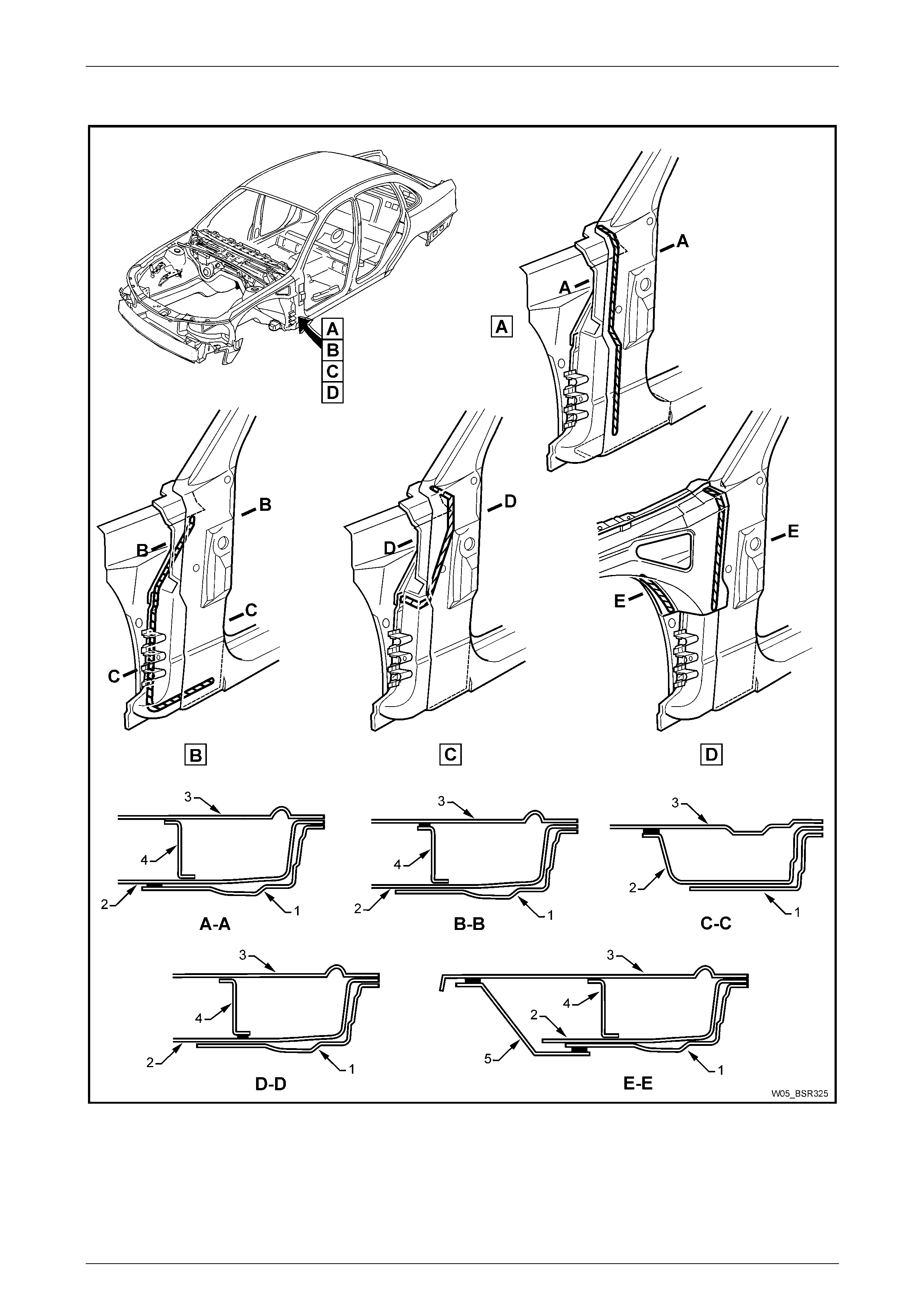
5.1 Acrylic Spot Weld Sealer (Item 2)
Figure 3 – 15
Legend
1 Door opening frame
2 Reinforcement – hinge pillar
3 Hinge pillar inner panel
4 Closing plate – hinge pillar
5 Front wheelhouse panel upper side rail
3 Body Construction Page 3–25
Page 3–25
Acrylic Spot Weld Sealer (Item 2) Continued
Figure 3 – 16
3 Body Construction Page 3–26
Page 3–26
5.2 Joint Sealer (Item 3)
Figure 3 – 17
3 Body Construction Page 3–27
Page 3–27
Joint Sealer (Item 3) Continued
Figure 3 – 18
3 Body Construction Page 3–28
Page 3–28
Joint Sealer (Item 3) Continued
Figure 3 – 19
3 Body Construction Page 3–29
Page 3–29
Joint Sealer (Item 3) Continued
Figure 3 – 20
3 Body Construction Page 3–30
Page 3–30
Joint Sealer (Item 3) Continued
Figure 3 – 21
3 Body Construction Page 3–31
Page 3–31
Joint Sealer (Item 3) Continued and Hand Putty (Item 4)
Figure 3 – 22
3 Body Construction Page 3–32
Page 3–32
5.3 Adhesive – Anti-Flutter (Item 5)
Figure 3 – 23
3 Body Construction Page 3–33
Page 3–33
Adhesive – Anti-Flutter (Item 5) Continued
Figure 3 – 24
3 Body Construction Page 3–34
Page 3–34
5.4 Adhesive – Structural (Item 6)
Figure 3 – 25
3 Body Construction Page 3–35
Page 3–35
5.5 Spray-on Deadener
Figure 3 – 26
3 Body Construction Page 3–36
Page 3–36
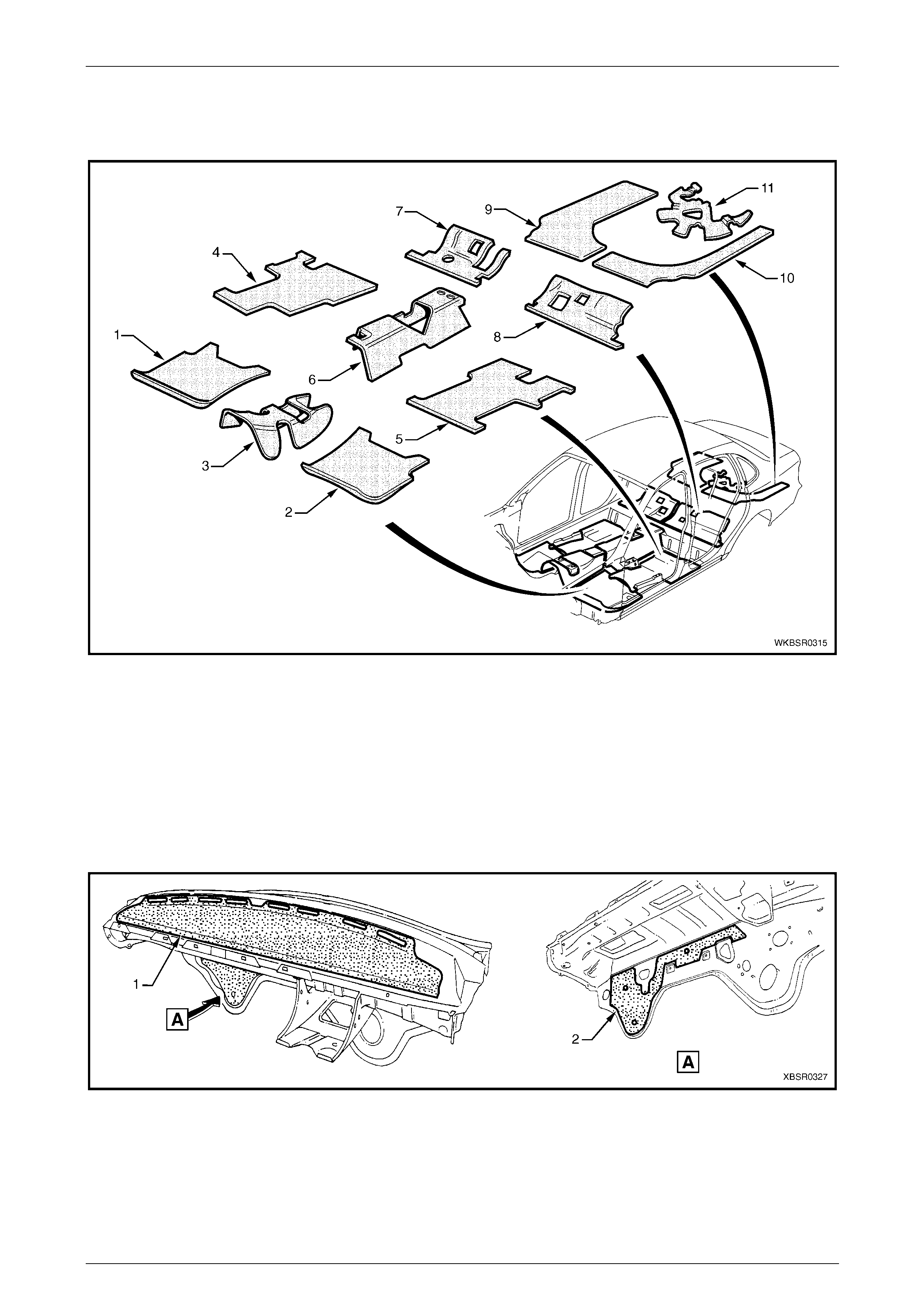
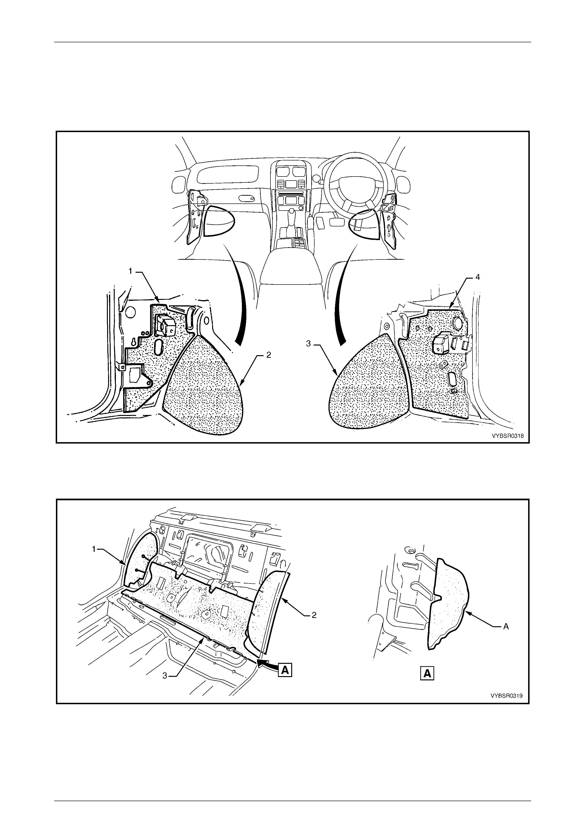
5.6 Deadener Panels and Insulators
The deadener pan els shown are heat fusible t ype. They are to be installed with the diamond embossed side do wn. Use a
heat gun, heat lamps or such to cure each de adener sheet.
Figure 3 – 27
Legend
1 Deadener – Front Floor, Right-hand
2 Deadener – Front Floor, Left-hand
3 Deadener – Front Floor, Centre
4 Deadener – Rear Floor, Right-hand
5 Deadener – Floor Rear, Left-hand
6 Deadener – Rear Floor, Centre
7 Deadener – Rear Seat Floor, Right-hand
8 Deadener – Rear Seat Floor, Left-hand
9 Deadener – Rear Compartment, Right-hand
10 Deadener – Rear Compartment, Left-hand
11 Deadener – Spare Wheel Well
The insulator (1) is self adhes ive, refer to Figure 3 – 28. To install, remove the backing paper and attach the insulator
ensuring any cut-outs align with brackets, etc. Smooth the insulator firmly into positio n. The deadener (2) is a heat cure
type and is attached as previously described.
Figure 3 – 28
Legend
1 Insulator – Dash Panel Upper 2 Deadener – Cockpit Module
3 Body Construction Page 3–37
Page 3–37
The deadeners and insulators in Figure 3 – 29 and F igure 3 – 30 are self adhesive. Remove the backing paper and
attach the insulator ensuring a ny cut-outs align with brackets etc. Smooth the insulator firmly into positi on.
NOTE
Ensure the notch in the rear s eat insulators (3) in
Figure 3 – 30 is aligned with the slot in the rear
seat ramp as shown A.
Figure 3 – 29
Legend
1 Insulator – Cowl Side, Left-hand
2 Deadener – Front Floor Extension, Left-hand 3 Deadener – Front Floor Extension, Right-hand
4 Insulator – Cowl Side, Right-hand
Figure 3 – 30
Legend
1 Insulator – Rear Seat Wheelhouse, Right-hand
2 Insulator – Rear Seat Wheelhouse, Left-hand 3 Insulator – Rear Seat
3 Body Construction Page 3–38
Page 3–38
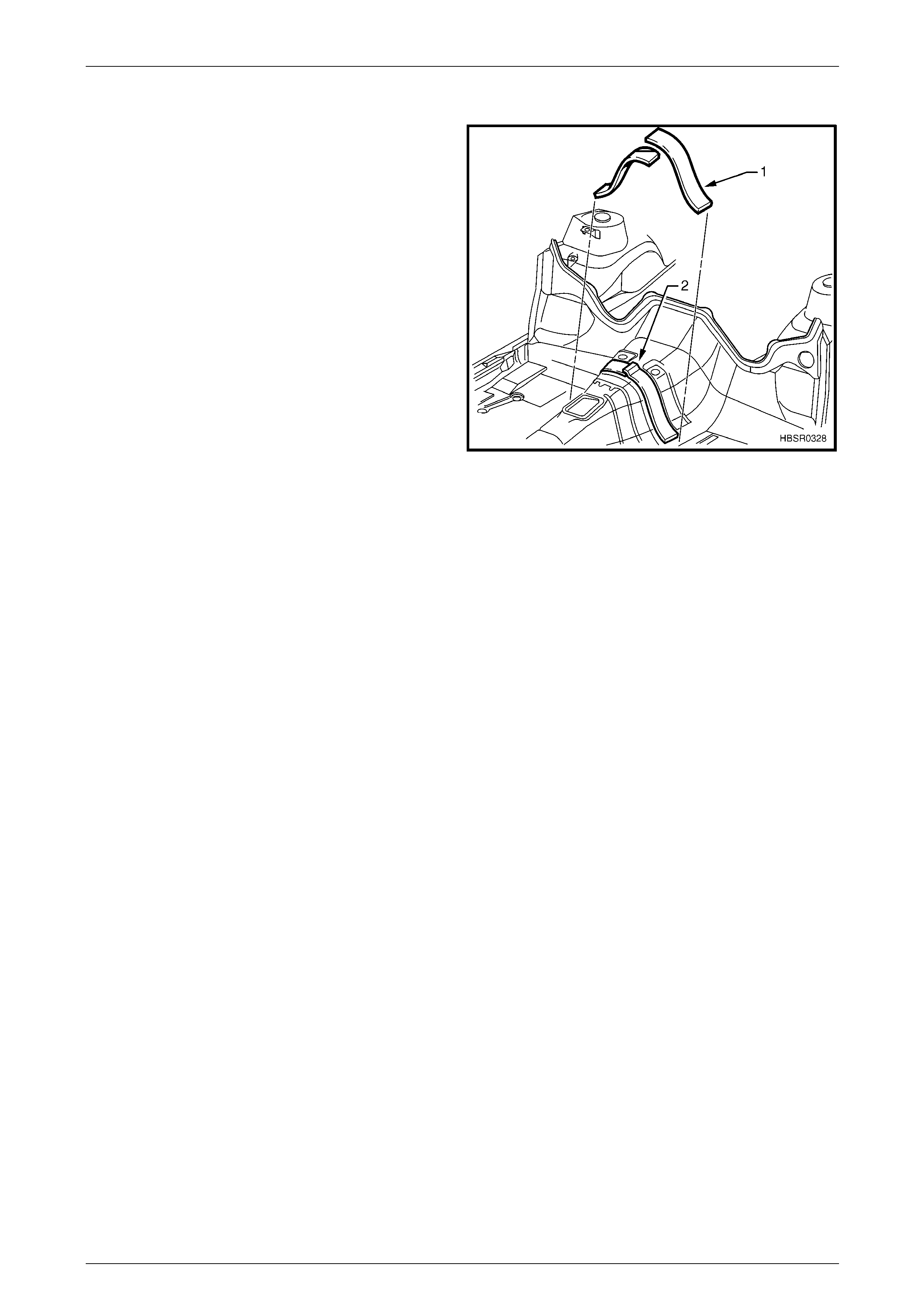
5.7 Fusible Reinforcement Patches
Two heat fusible reinforcing patches (1) are applied to the
front floor tunnel which provide stiffness and aid in the
reduction of Noise, Vibration and Hars hness (NVH).
The sheets are pliable in their uncured state and are applied
to the vehicle prior to paint baking. The heat required to cure
and harden the sheets is approximately 120° C, and once
cured the sheets become a structural part of the vehicle.
Therefore, if the front floor assembly is replaced, the
patches must also be replaced.
Lower curing temperature replacement patches are
available from an Authorised Dealer.
Replace
1 Where possible, apply th e patches to the new floor
prior to painting.
2 Ensure the surface is clean, dry and free from weld
spatter, etc.
3 Apply the patches in the locations shown ensuring an
overlap of 5 – 10 mm (2).
4 Using a heat gun or dryi ng lamps, etc. evenly heat the
material until it smoothes and the edges begin to
‘soften’.
5 Smooth the material down with a roller or like, to
ensure no air bubbles are present and to maximise
adhesion.
6 Once cooled, the material should feel hard.
Figure 3 – 31
3 Body Construction Page 3–39
Page 3–39
6 Cavity Wax
The body and structural panels are constructed from high quality corrosion resistant materials. During manufacture,
cavity wax is applied to the ar eas shown to further increase the vehicle’s anti-corrosive pr operties.
Following repairs, to maintain the anti-corrosive properties of the vehicle, o nce the paint is thoroughly dry apply cavity
wax to the areas shown belo w, a nd within any repaired box secti ons or areas inaccessible to paint. Refer to the table for
equivalent products to those used in man ufacture.
Cavity Wax Equivalents
Item No. Equivalent Manufacturer Equivalent Product Name
8 Henkel
Terotex HV 8377/65
Nox Rust Hi-Wax 100B
Terasol 800113 (Aerosol pack)
Figure 3 – 32
3 Body Construction Page 3–40
Page 3–40
Figure 3 – 33
3 Body Construction Page 3–41
Page 3–41
7 Bumper Impact Bar Assemblies
The bumper impact bar assemblies not only act as a mount and support for the bumper fascias, but are also critical in
the dispersion of crash energy. Hence, they play an integral role in the operation of the vehicle’s safety systems. Repair
of the bar assemblies should be limited to replacement, as straightening and/or heatin g can weaken a bar assembly,
potentially resulting in incorrect airbag and seatbelt pretensioner operation.
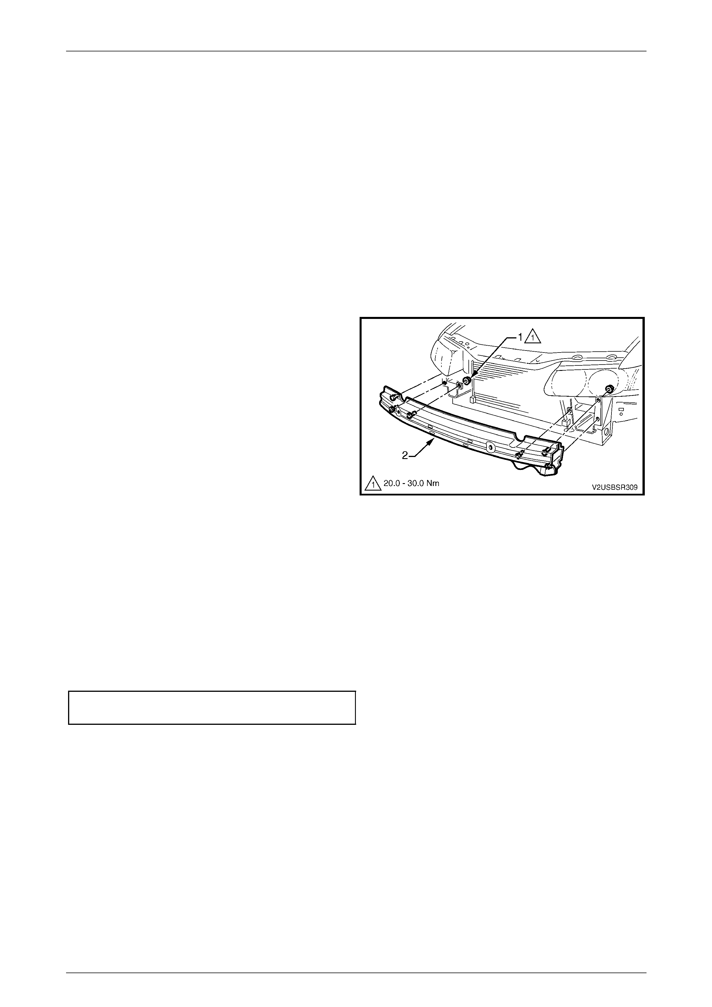
7.1 Front
Remove
1 Remove the front bumper fascia assembly, refer to Section 1D Bumper Bars in the MY2005 WL Service
Information.
2 If fitted, remove the radiator air lower baffle, refer to Section 6B1 Engine Cooling in the MY2005 WL Service
Information.
3 Remove the nuts (1), three places each side, attaching
the bar assembly (2) to the vehicle.
4 Remove the bar assembly.
Figure SectNum – 34
Reinstall
NOTE
Check the vehicle’s front body dimensions as
required to ensure correct alignment, refer to
Section 1A2 Body Dimensions.
1 Fit the bar assembly in position and attach each nut. Do n ot tighten.
2 Ensure the bar assembly is correctly positioned centrally a nd tighten the nuts to the specified torque.
Front Bumper Impact Bar Assembly
Attaching Nut Torque Specification.........20.0 – 30.0 Nm
3 Refit the front bumper fascia assembly, refer to Section 1D Bumper Bars in the MY2005 WL Service Information.
3 Body Construction Page 3–42
Page 3–42
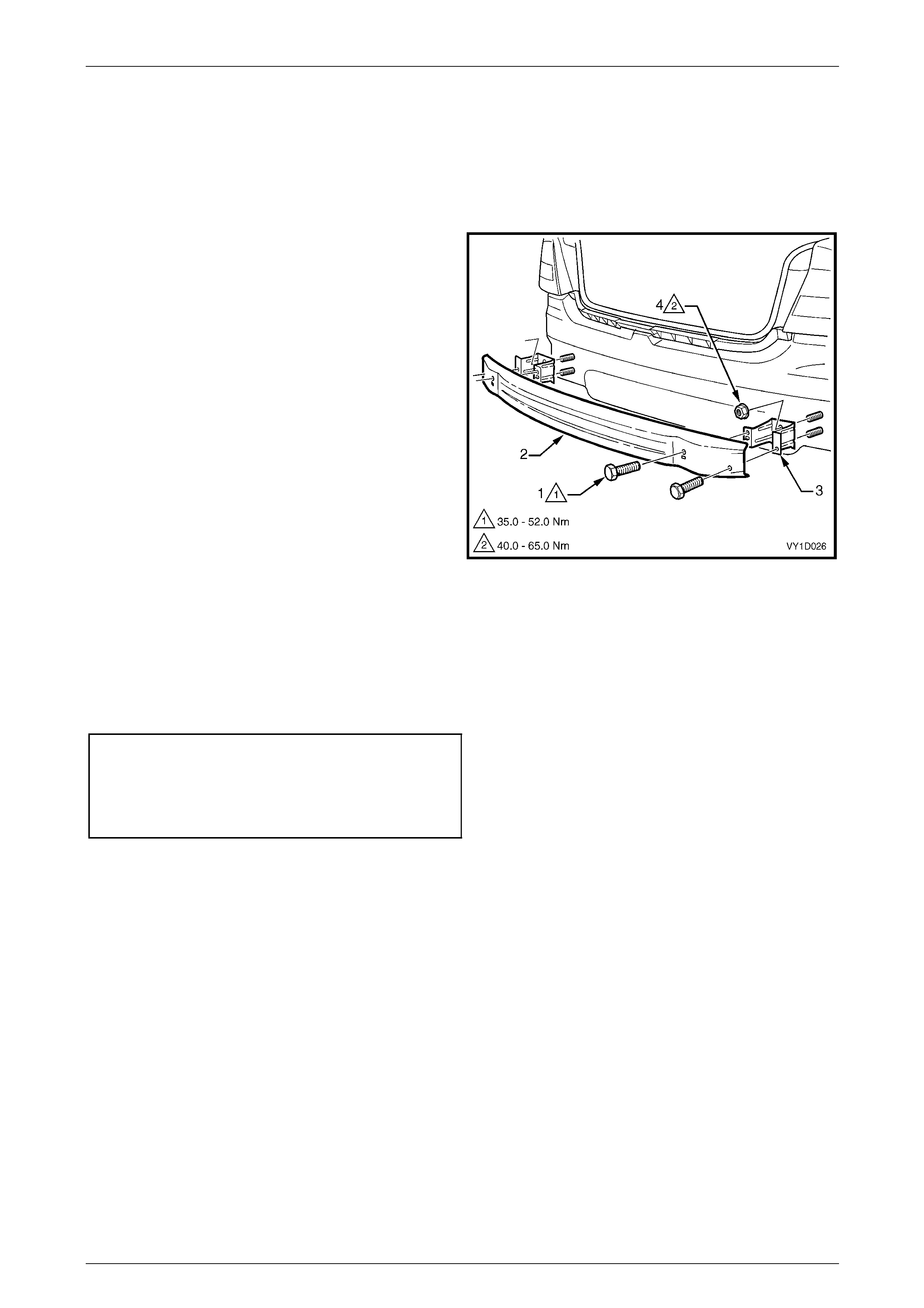
7.2 Rear
Remove
1 Remove the rear bumper fascia assembly, refer to Section 1D Bumper Bars in the MY2005 WL Service
Information.
2 Remove the screws (1), two places each side ,
attaching the rear bumper im pact bar (2) to the rear
bumper impact bar bracket assembly (3).
3 Remove the bar.
4 If required, remove the two nuts (4), attaching the
bracket assembly to the vehicle and remove the
bracket.
Figure SectNum – 35
Reinstall
1 Fit the bracket assemblies in position and attach the nuts. Tighten to the specified torque.
2 Fit the bar to the bracket assemblies and fit each screw. Do not tighten.
3 When all screws are installed, check the bar is centralised. Tighten the bolts to the specified torque.
Rear Bumper Impact Bar Bracket
assembly Attaching Nut
Torque Specification ...............................49.0 – 65.0 Nm
Rear Bumper Impact Bar Attaching
screw Torque Specification.....................35.0 – 52.0 Nm
3 Body Construction Page 3–43
Page 3–43
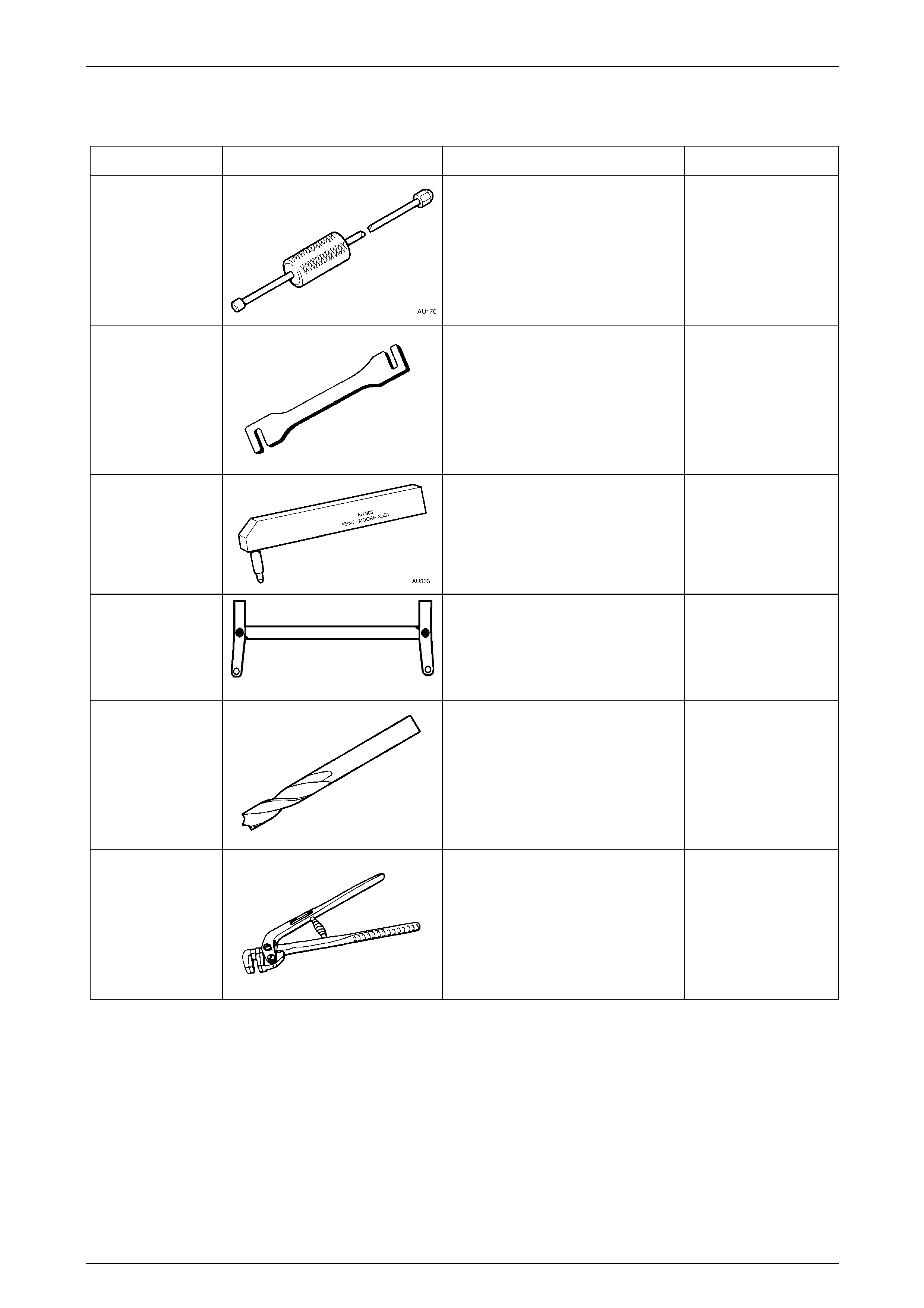
8 Special Tools
Tool Number Illustration Description Tool Classification
AU170 Door Hinge Sleeve Remover
Used for removing door hinge pivot
sleeves
AU184 Door Hinge Setting Tool
Used to adjust door alignment.
AU303
Door Hinge Sleeve Installer
Used to install door hinge piv ot
sleeves
AU458
Rear Crossmember Centring Tool
Used when any servic e operation
requires removal / reinstallation of
rear suspension frame assembly, or
when checking rear end alignment.
N/A Spot Cutting Tool
Commercially available
Used for separating spot welds
N/A Flanging Tool
Commercially available
Used for making a joggle to form a lap
joint on overlapping panels.
3 Body Construction Page 3–44
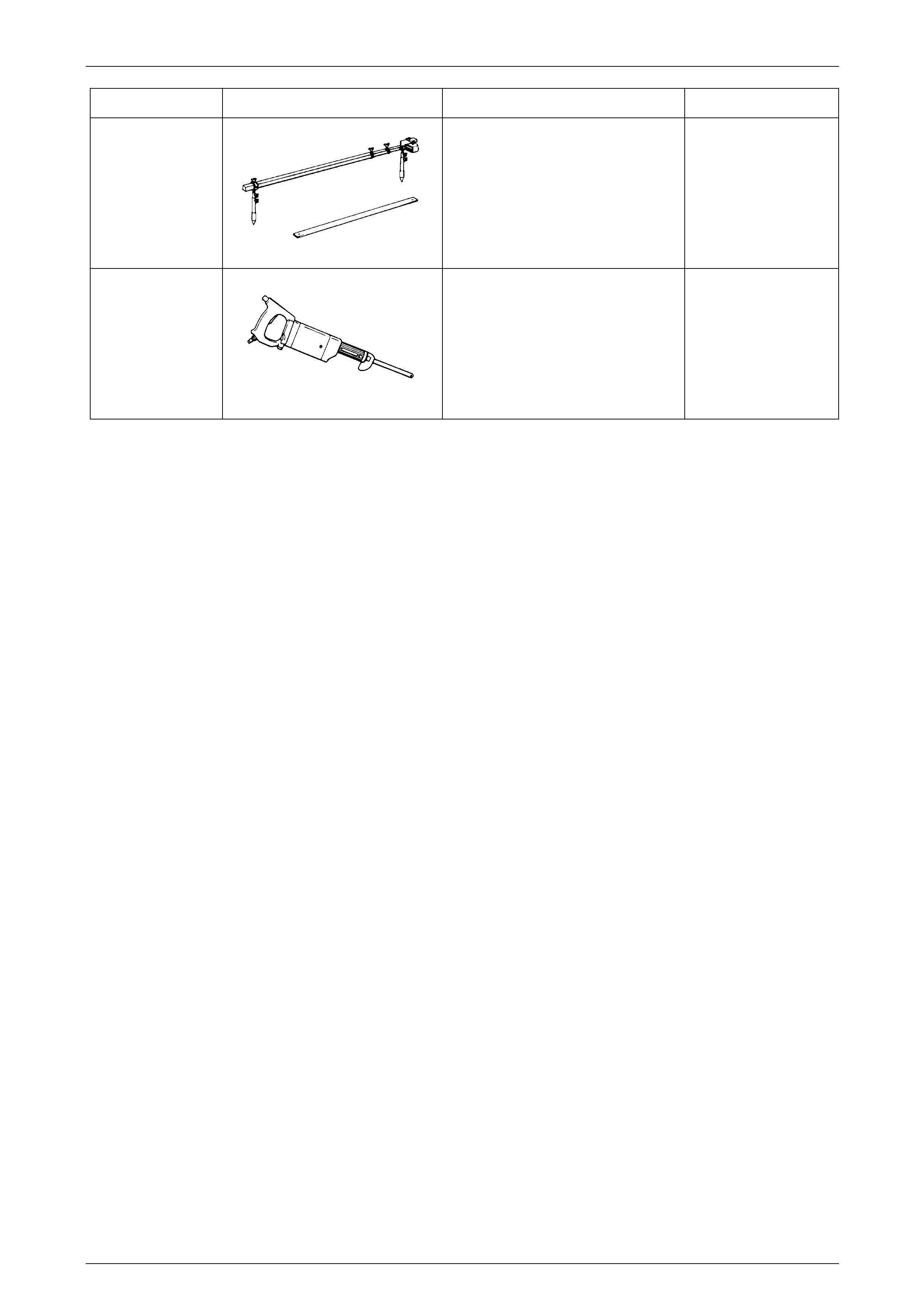
Page 3–44
Tool Number Illustration Description Tool Classification
N/A Tracking Gauge
N/A Power Saw
Commercially available
Used for cutting panels. An angle
grinder may also be used when
deemed more appropri ate for the task