
4 Front End Page 4-1
Page 4-1
Section 4
Front End
ATTENTION
Before performing any service operation or other procedure described in this Section, refer to Section 00
Warnings, Cautions and Notes for correct workshop practices with regard to safety and/or property damage.
The structure of the body shell has been
developed using complex design and
development techniques. In addition to
meeting all required standards, the vehicle
body is also a critical part of the overall safety
systems. It is therefore imperative the repair
procedures described here are adhered to
during all vehicle body repairs.
1 General Description ...............................................................................................................................2
1.1 Front End Components......................................................................................................................................... 2
2 Service Operations.................................................................................................................................4
2.1 Front End Panel Assembly – Replace.................................................................................................................. 4
Remove................................................................................................................................................................... 4
Replace................................................................................................................................................................... 5
2.2 Headlamp Panel – Replace ................................................................................................................................... 8
Remove................................................................................................................................................................... 8
Replace................................................................................................................................................................. 10
2.3 Front Wheelhouse Bracket Assembly, Front Wheelhouse Bracket and Front Bumper Impact Bar Bracket
Assembly – Replace............................................................................................................................................ 12
Remove................................................................................................................................................................. 12
Replace................................................................................................................................................................. 13
2.4 Radiator Lower Support Assembly – Replace................................................................................................... 15
Remove................................................................................................................................................................. 15
Replace................................................................................................................................................................. 16
2.5 Front Wheelhouse Panel Upper Side Rail – Replace........................................................................................ 17
Remove................................................................................................................................................................. 17
Replace................................................................................................................................................................. 18
2.6 Front Wheelhouse Panel Assembly – Replace.................................................................................................. 19
Remove................................................................................................................................................................. 19
Replace................................................................................................................................................................. 20
2.7 Front Wheelhouse Panel and Front Side Rail – Partial Replace...................................................................... 22
Remove................................................................................................................................................................. 22
Replace................................................................................................................................................................. 23
2.8 Front Side Rail Assembly– Replace................................................................................................................... 25
Remove................................................................................................................................................................. 25
Replace................................................................................................................................................................. 27
2.9 Brake Pressure Modulator Bracket Assembly and Multiuse Relay Housing Bracket.................................... 29
Remove................................................................................................................................................................. 29
Replace................................................................................................................................................................. 29
Brake Pressure Modulator Bracket Assembly.................................................................................................. 30
Multiuse Relay Housing Bracket....................................................................................................................... 30
4 Front End Page 4-2
Page 4-2
1 General Description
This Section describes the replacement procedures for the front-end components of the bod y structure. Removal of bolt-
on panels and mechanical co mponents is not covered. Reference must be made to the appropriate Secti on of the
MY2005 WL Service Information.
When repairing the front end of the vehicle, care must be taken to ensure the structure is returned to its original
production configuration for th e occupant protection system to operate correctly. This is especially im portant with repairs
to the front side rails.
Incorrect repair of the front side rails could cause the seatbelt pretensioners and airbag(s) to oper ate incorrectly, affecting
the timing of deployment during a collision.
The following strategy must be used when repairing the fro nt side rai ls:
1 If minor damage has occurred to the front section of the front side rail, which does not inv olve significant creasing
or crumple of the rail, it may be straightened.
2 If significant creasing or crumple of the rail has occurred, but is restricted to the area forward of the front
suspension crossmember, the front side rail may be cut at a point between the two crossmember mounting bolts
and a partial section welded in place as described in this Section.
3 If significant creasing or crumple of the rail has occurred and continues rear ward of the front suspension
crossmember, the full front side rail assembly must be replaced.
NOTE
It is imperative the correct body adhesives,
sealers, deadeners and cavity waxes are used
when repairing the body structure of vehicle.
Refer to Section 3 Body Construction for details
of the correct materials and their commercially
available equivalents.
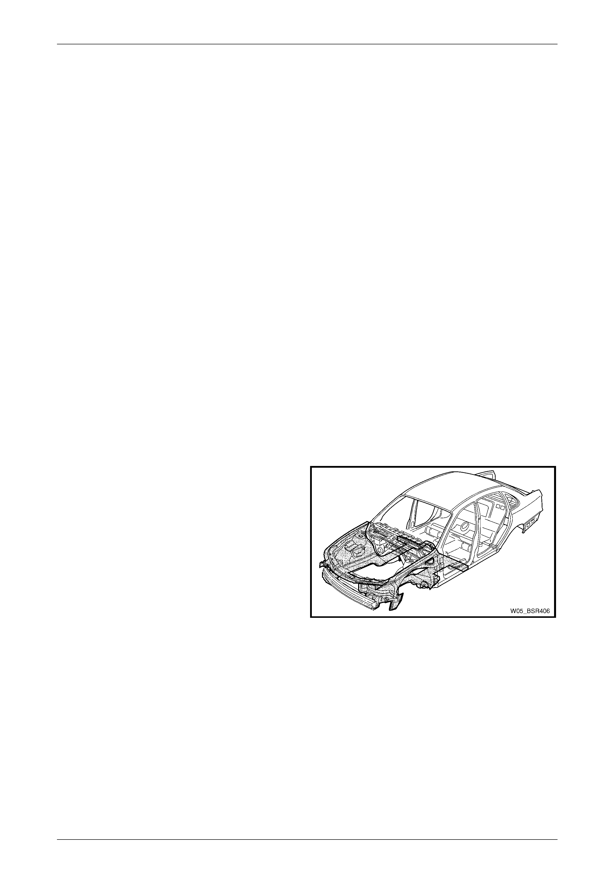
1.1 Front End Components
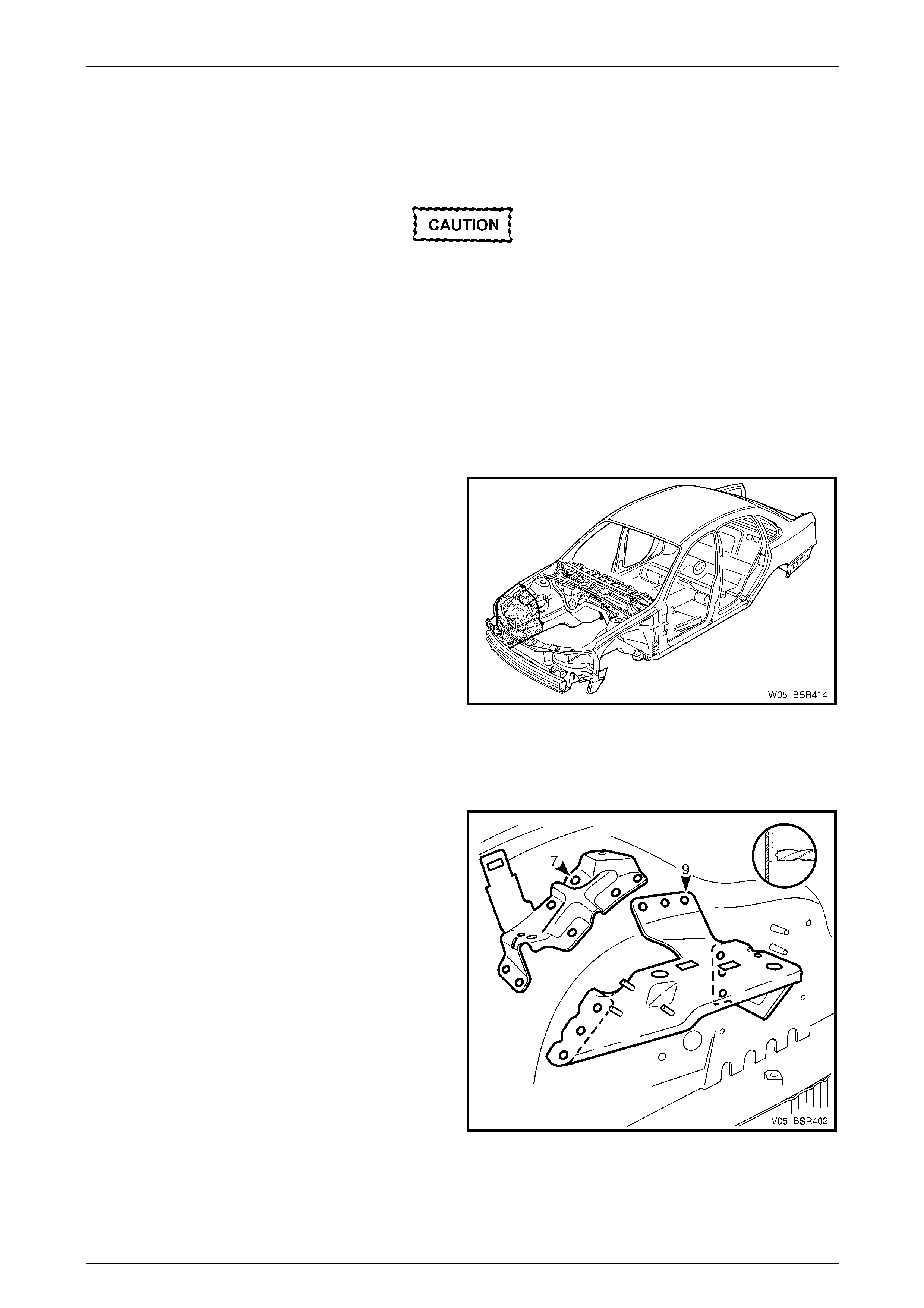
The shaded components in Figure 4 – 1 are those dealt with
in this Section.
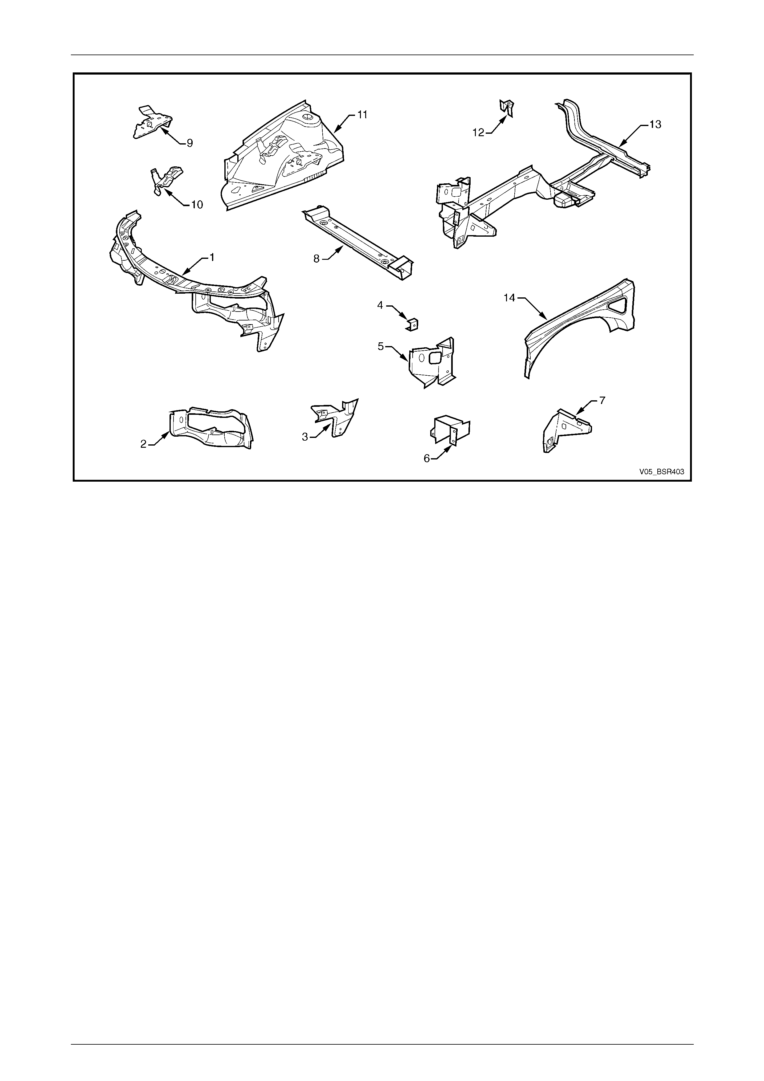
The components and assemblies shown in Figure 4 – 2 are
the serviceable parts that form the basis of the repair
procedures in this Section. For a detailed view of the body
components, refer to Section 3 Body Construction.
NOTE
Always refer to an Authorised Retailer for spare parts
availability configurations.
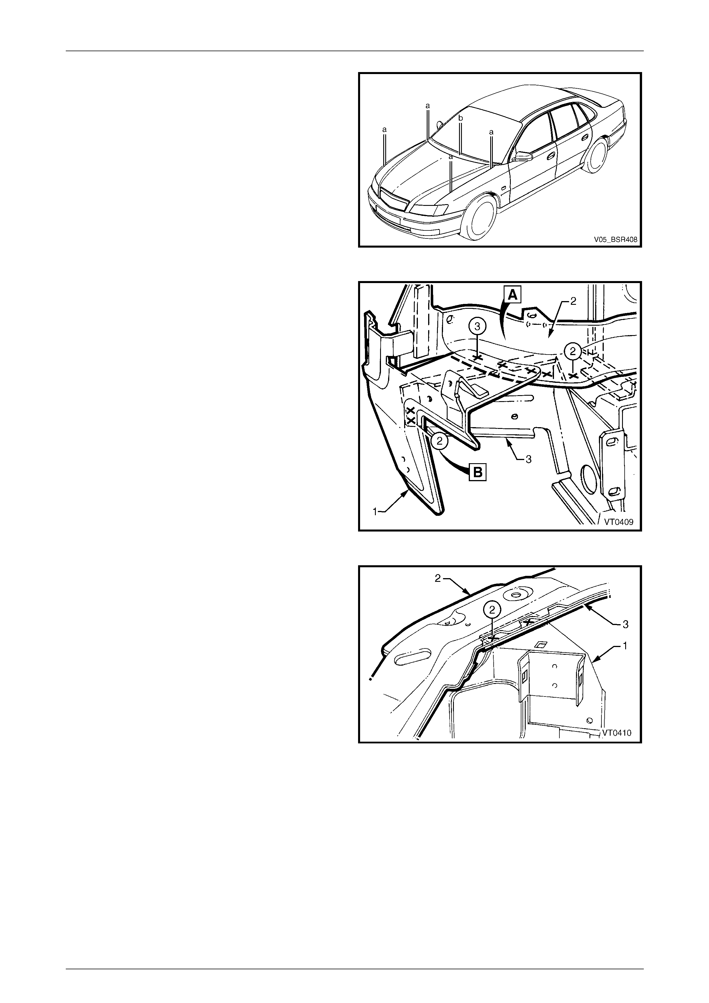
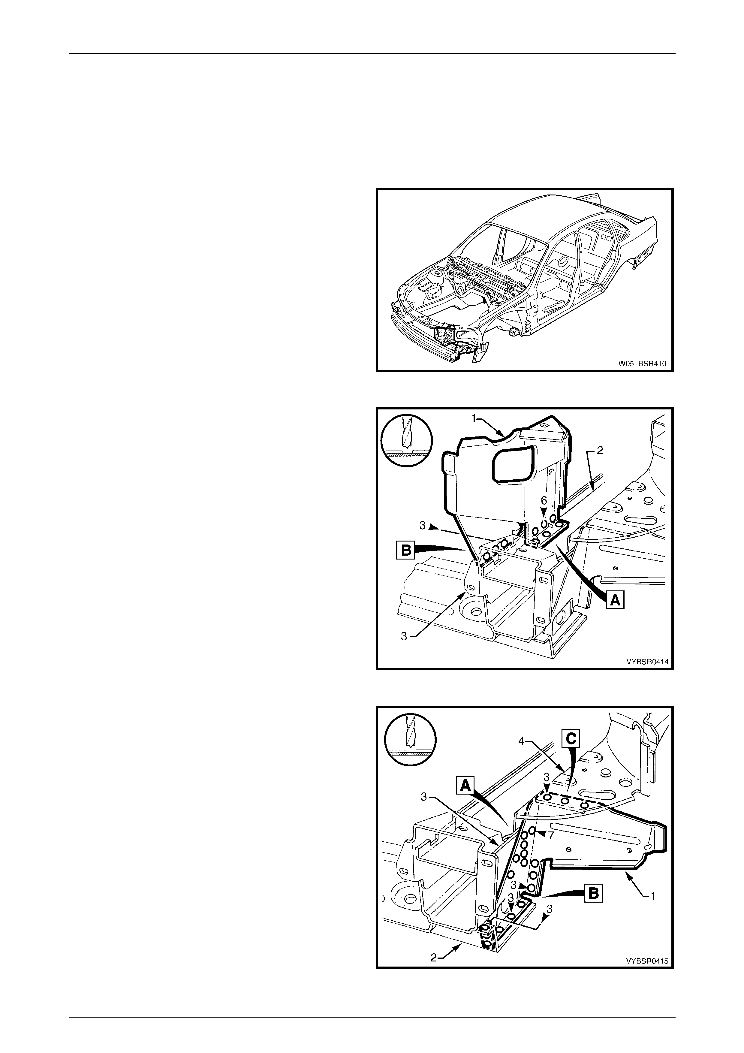
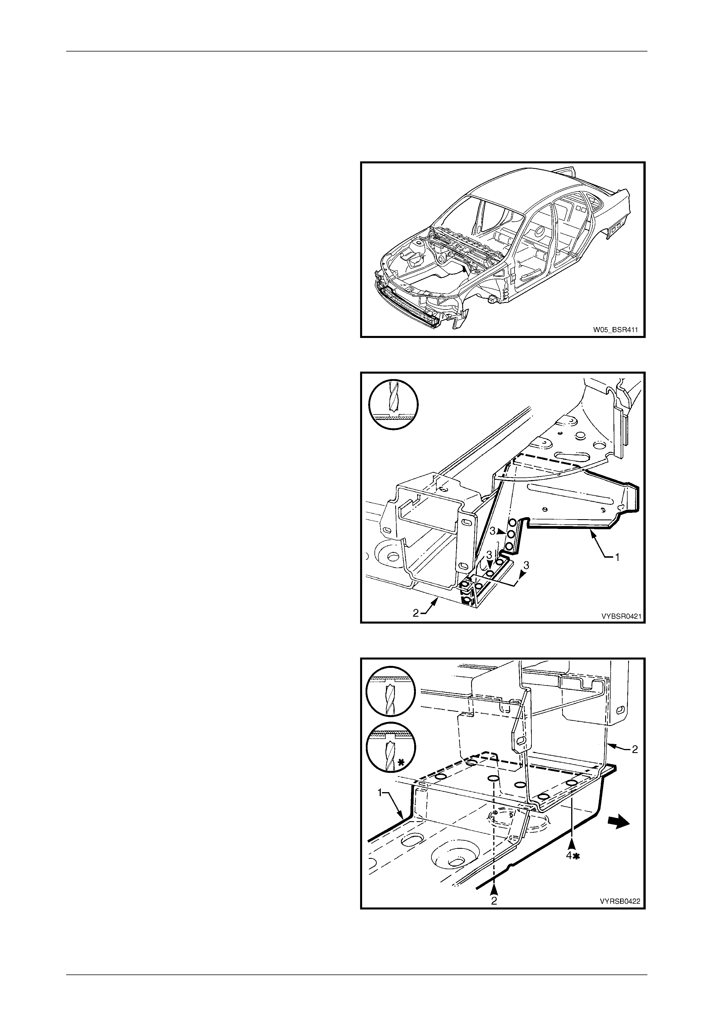
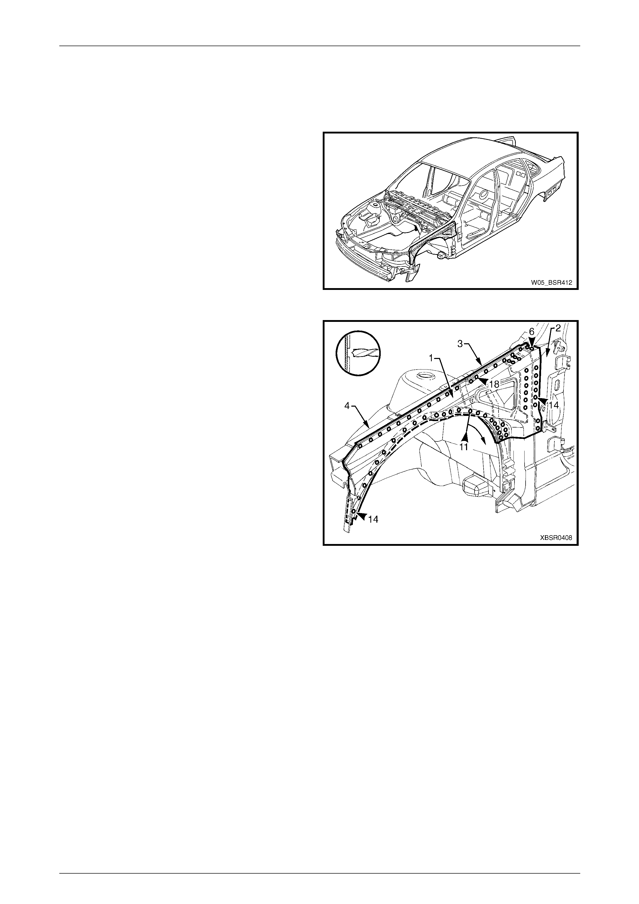
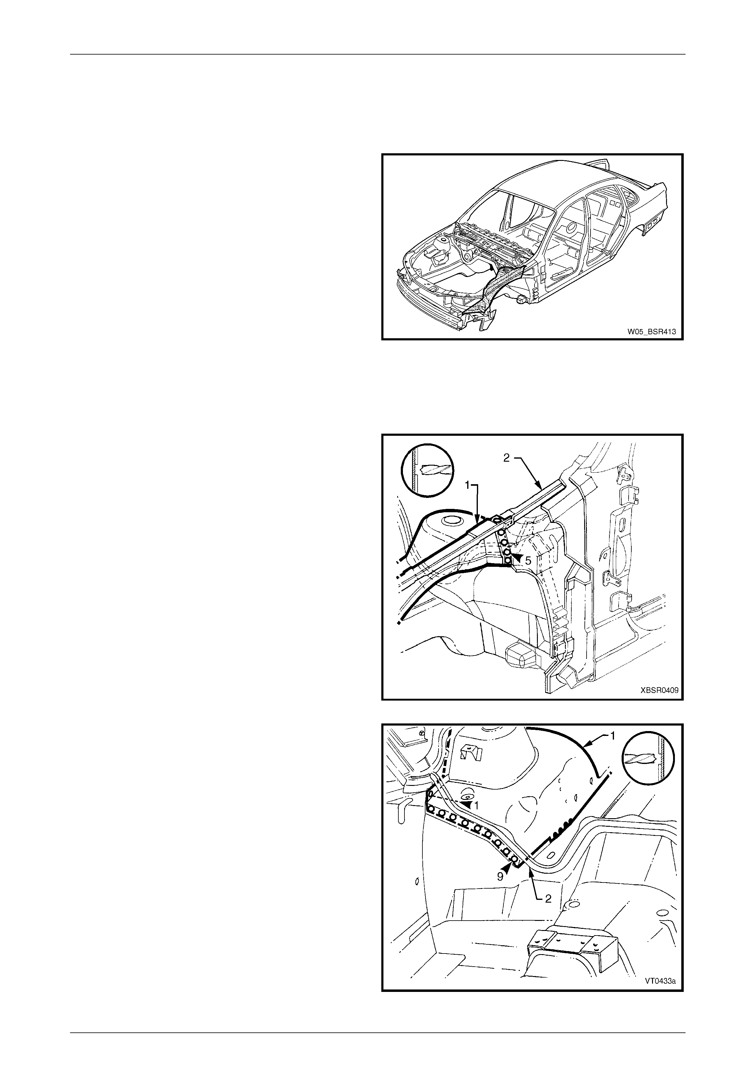
Figure 4 – 1
4 Front End Page 4-3
Page 4-3
Figure 4 – 2
Legend
1 Front End Panel Assembly
2 Headlamp Panel, Right-hand / Left-hand
3 Headlamp and Front Fascia Mount Bracket, Right-hand /
Left-hand
4 Radiator Side Mounting Bracket, Right-hand / Left-hand
5 Front Wheelhouse Bracket Assembly, Right-hand / Left-
hand
6 Front Bumper Impact Bar Bracket, Right-hand / Left-hand
7 Front Wheelhouse Panel Bracket, Right-hand / Left-hand
8 Radiator Lower Support Assembly
9 Brake Pressure Modulator Bracket Assembly
10 Multiuse Relay Housing Bracket
11 Front Wheelhouse Panel Assembly, Right-hand / Left-hand
12 Horn Bracket Assembly
13 Front Side Rail Assembly, Right-hand / Left-hand
14 Front Wheelhouse Panel Upper Side Rail, Right-hand / Left-
hand
NOTE
• Front end panel assembl y (1) includes parts 2
and 3.
• Front side rail assembly (13) includes parts 4,
5, 6 and 7.
4 Front End Page 4-4
Page 4-4
2 Service Operations
2.1 Front End Panel Assembly – Replace
Remove
1 Remove the adjacent bolt-on panels a nd components
as described in the appropriate Section of the MY2005
WL Service Information.
2 Remove the front bumper impact bar assembly,
refer to Section 3 Body Construction.
3 If required, mount the vehicle on a suitable ji g or
secure an appropriate tool between the two front
wheelhouse panels to maintain correct body alignment
when the front panel is removed.
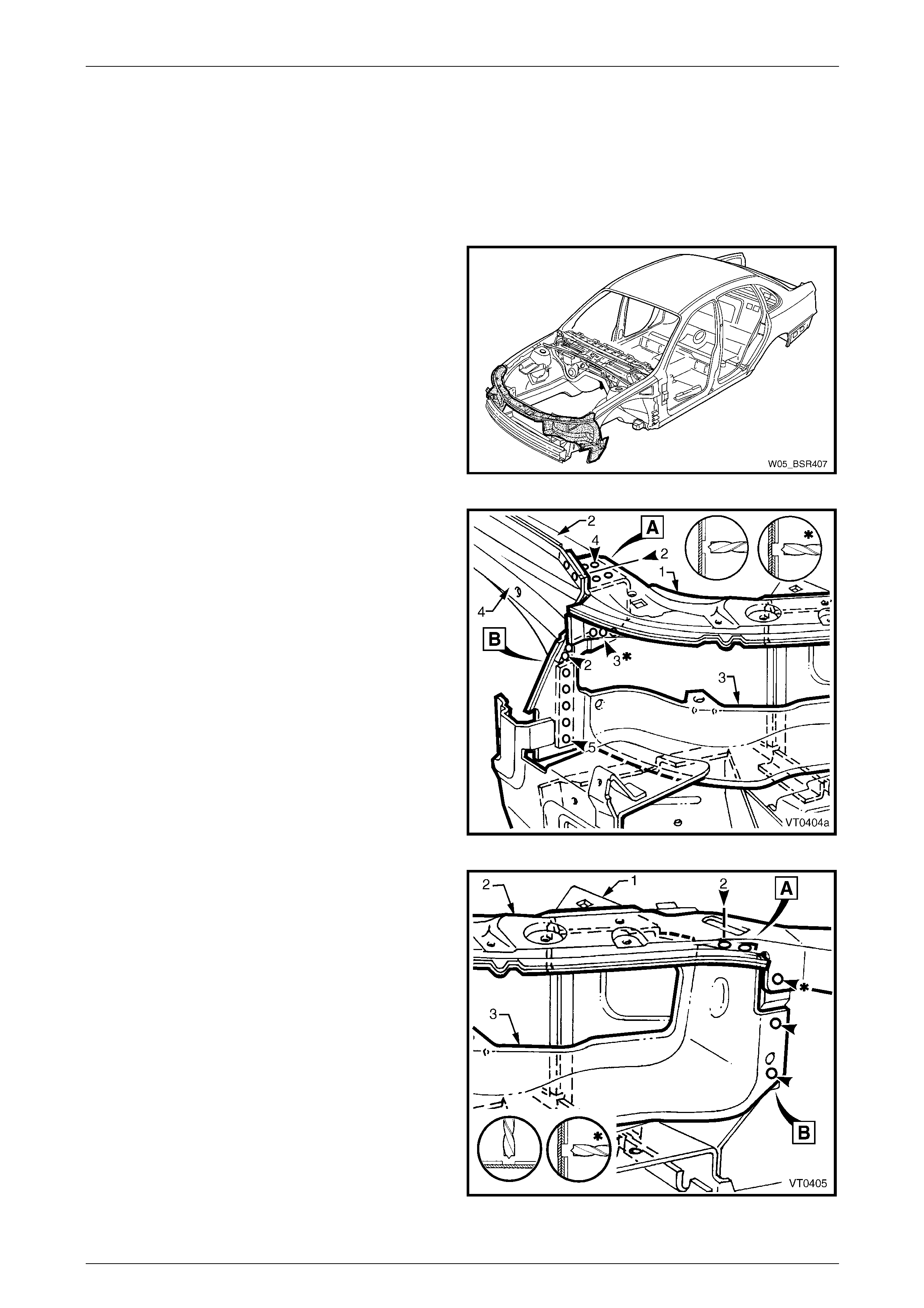
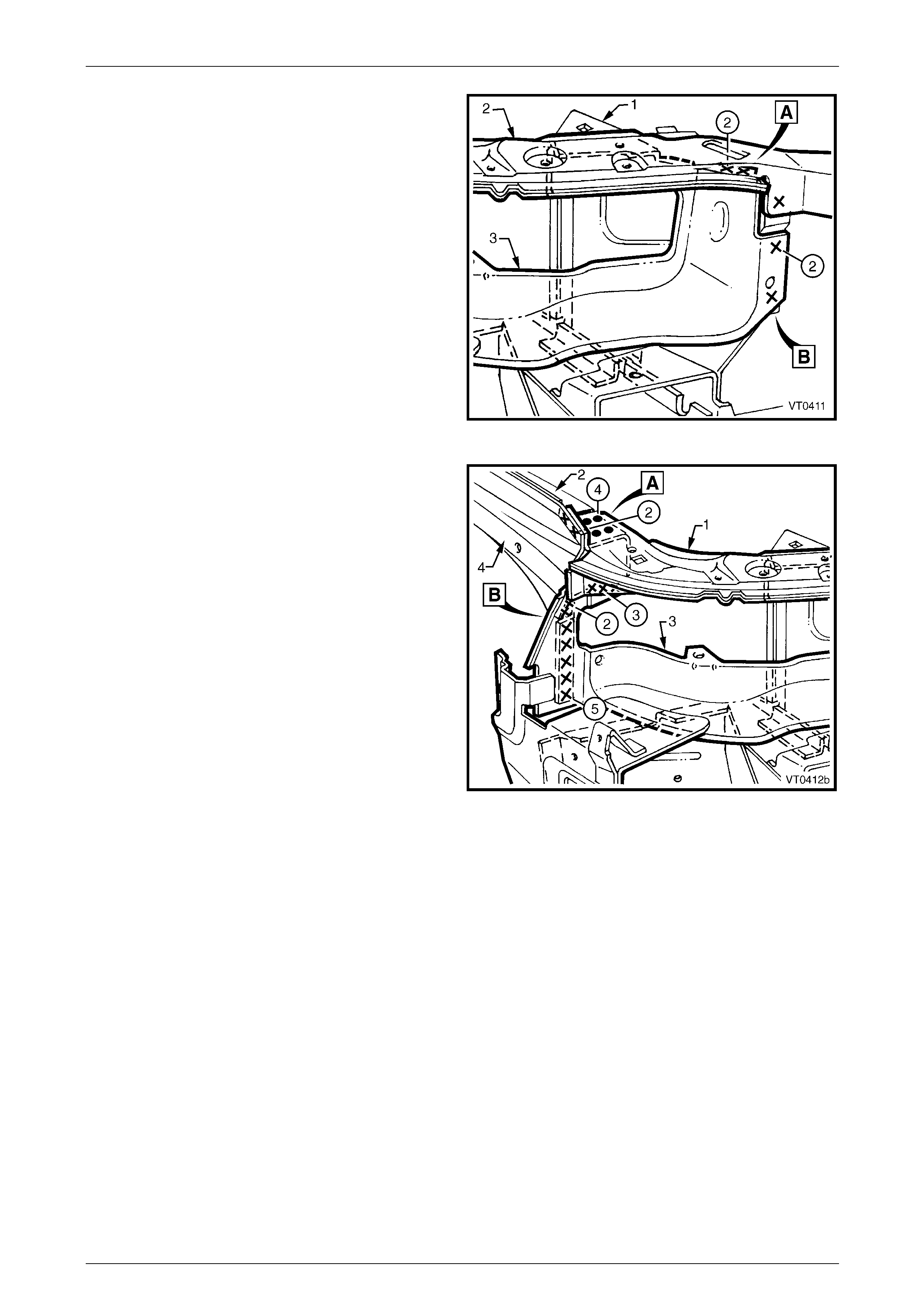
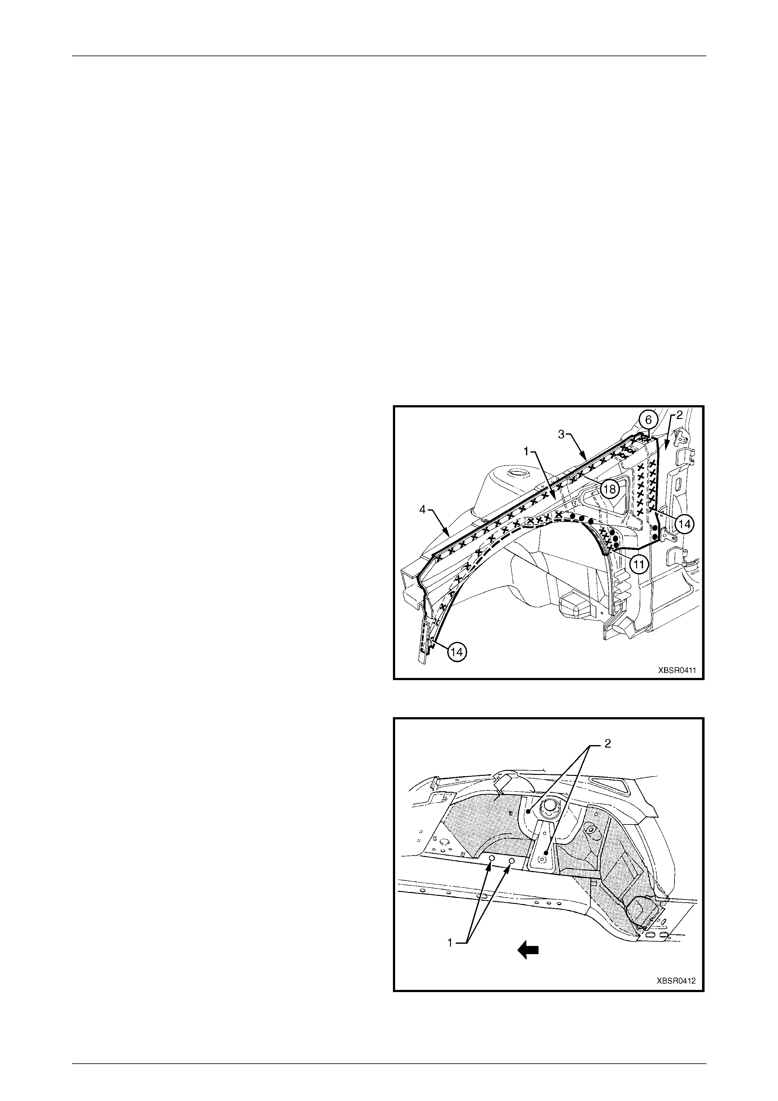
Figure 4 – 3
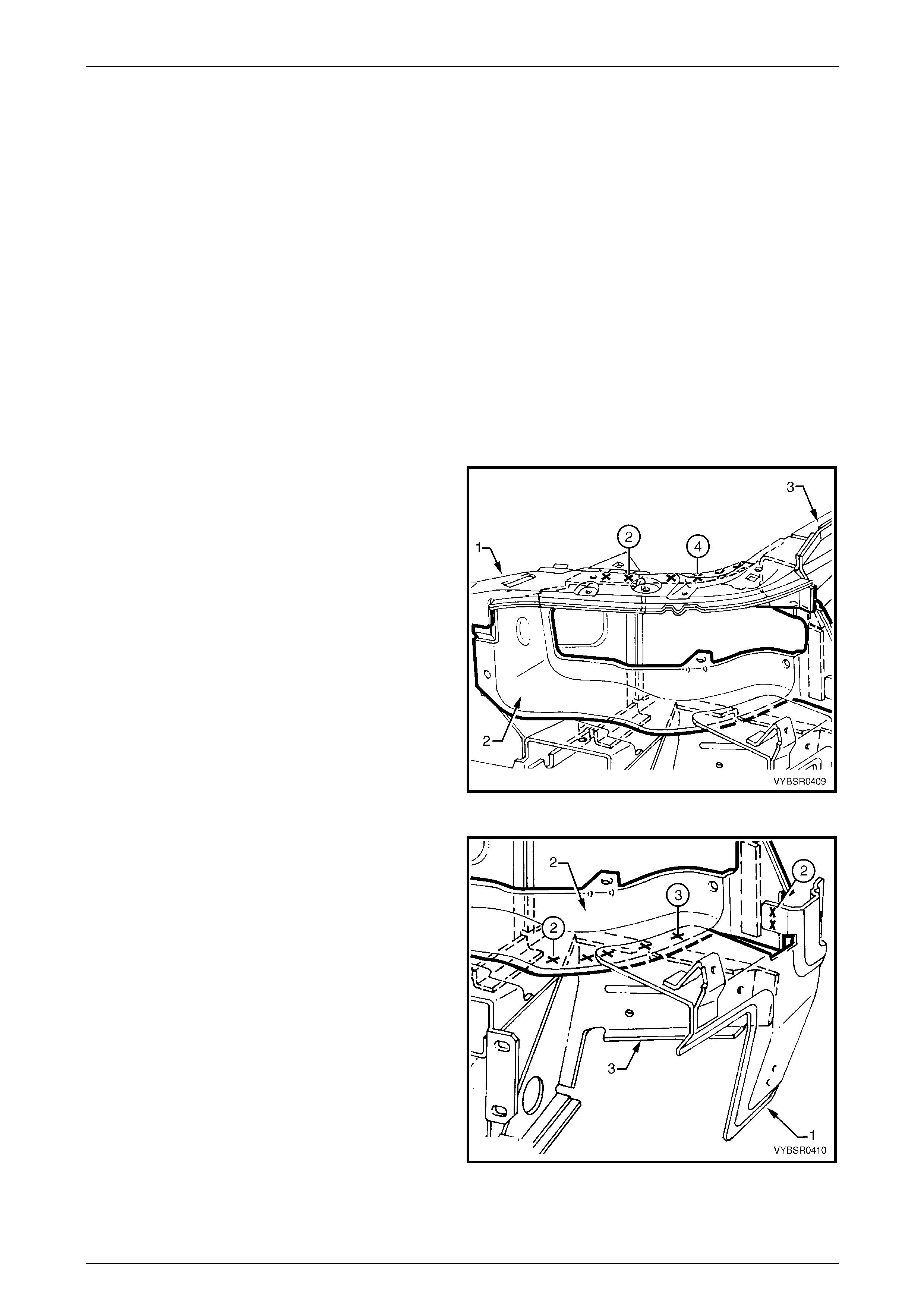
4 On each side of the vehicle, spot cut the welds
attaching the front end panel upp er (1) to the front
wheelhouse panel (2). Four welds are on the
horizontal surface and two on the vertical flange.
Refer to weld group A.
5 Spot cut a total of 10 welds on each side of the
vehicle, attaching the headlamp panel (3) to the front
wheelhouse panel (2) and to the wheelhouse upper
side rail (4). Refer to weld group B.
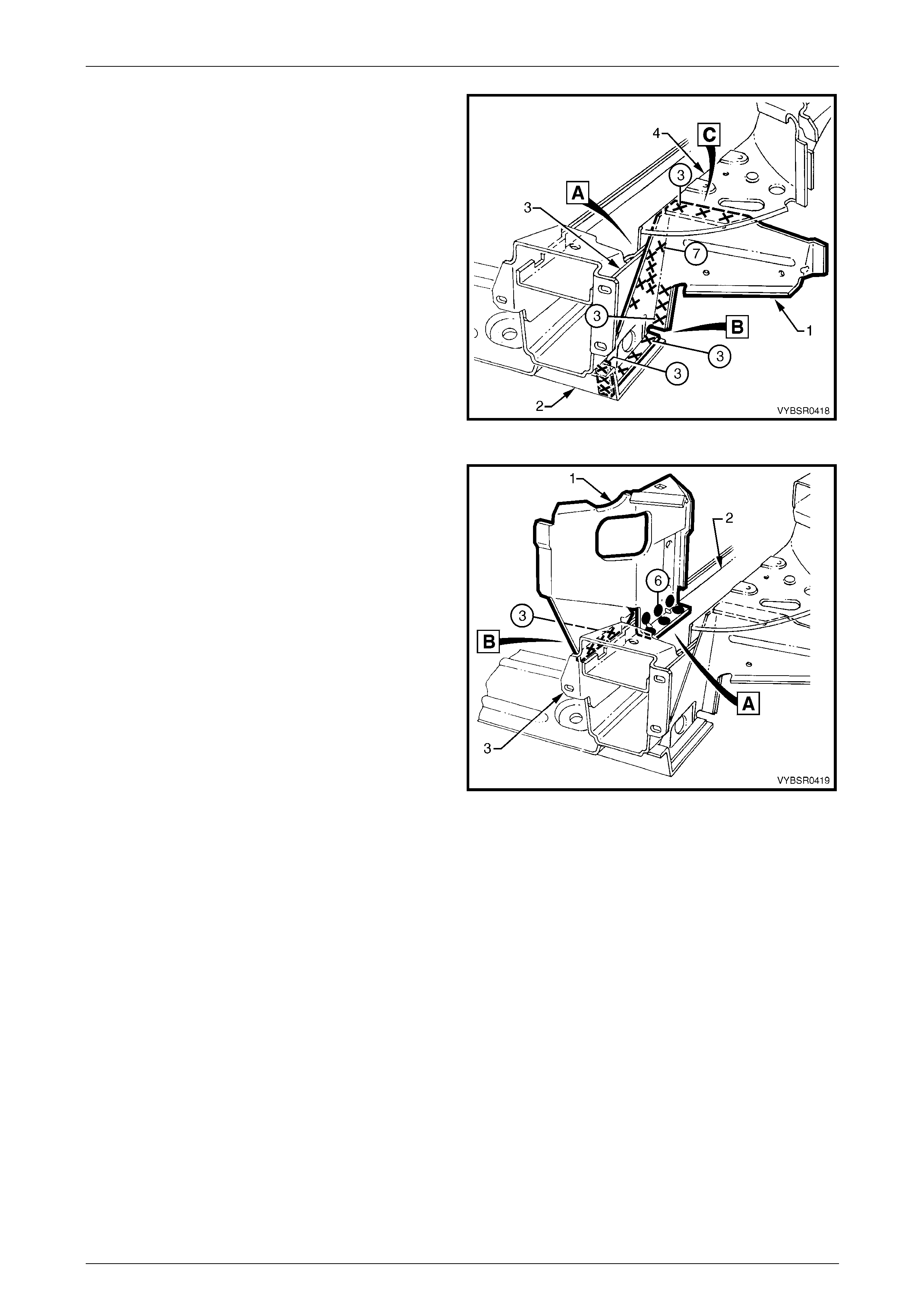
Figure 4 – 4
6 On each side of the vehicle, spot cut the welds
attaching the front wheelhouse bracket assembly (1)
to the front end panel upper (2) and headlamp panel
(3). Refer to weld group A.
7 On each side of the vehicle, spot cut the three welds
on the vertical flange attaching the headlamp panel
and front end panel upper to the front wheelhouse
bracket assembly. Refer to weld group B.
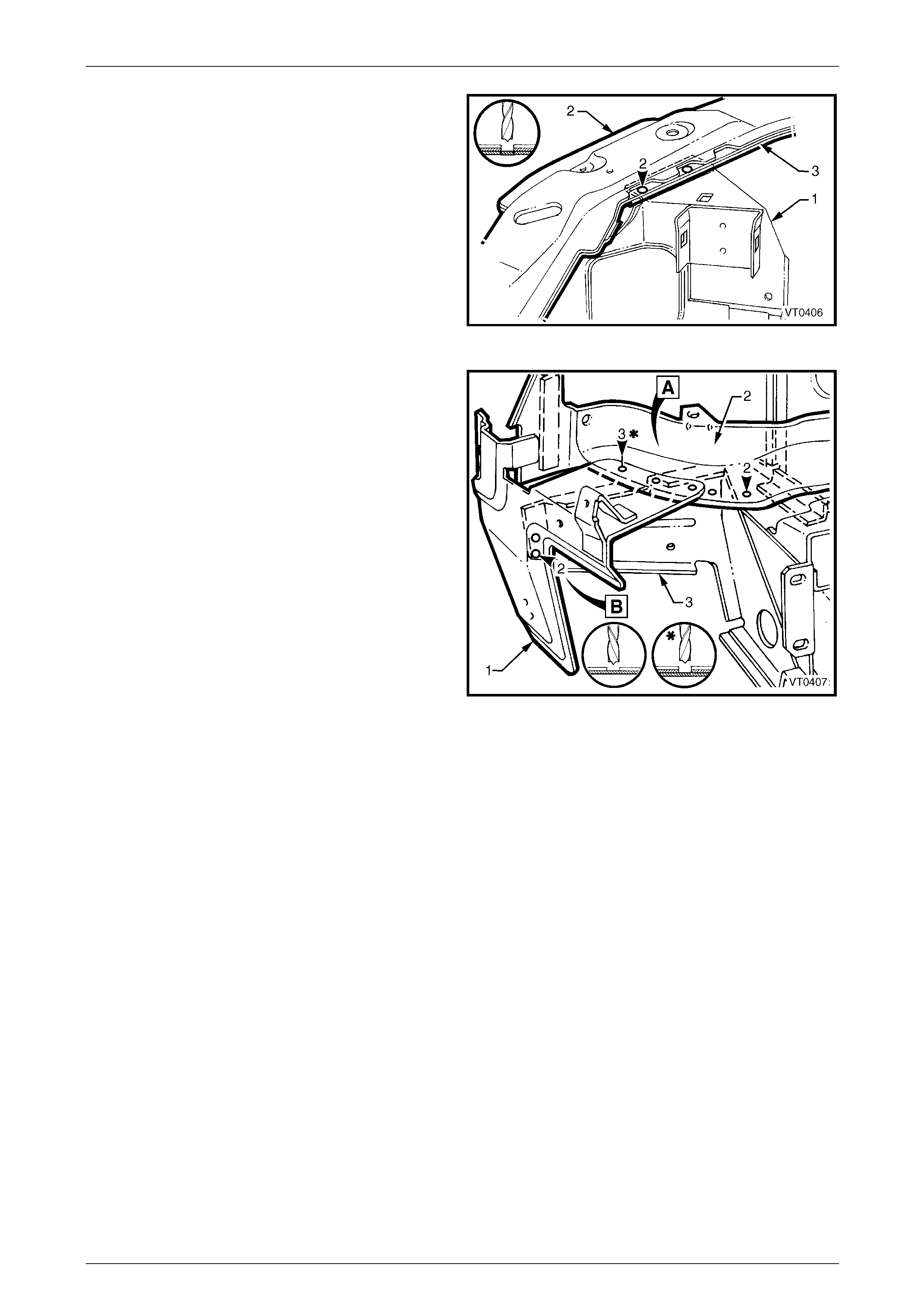
Figure 4 – 5
4 Front End Page 4-5
Page 4-5
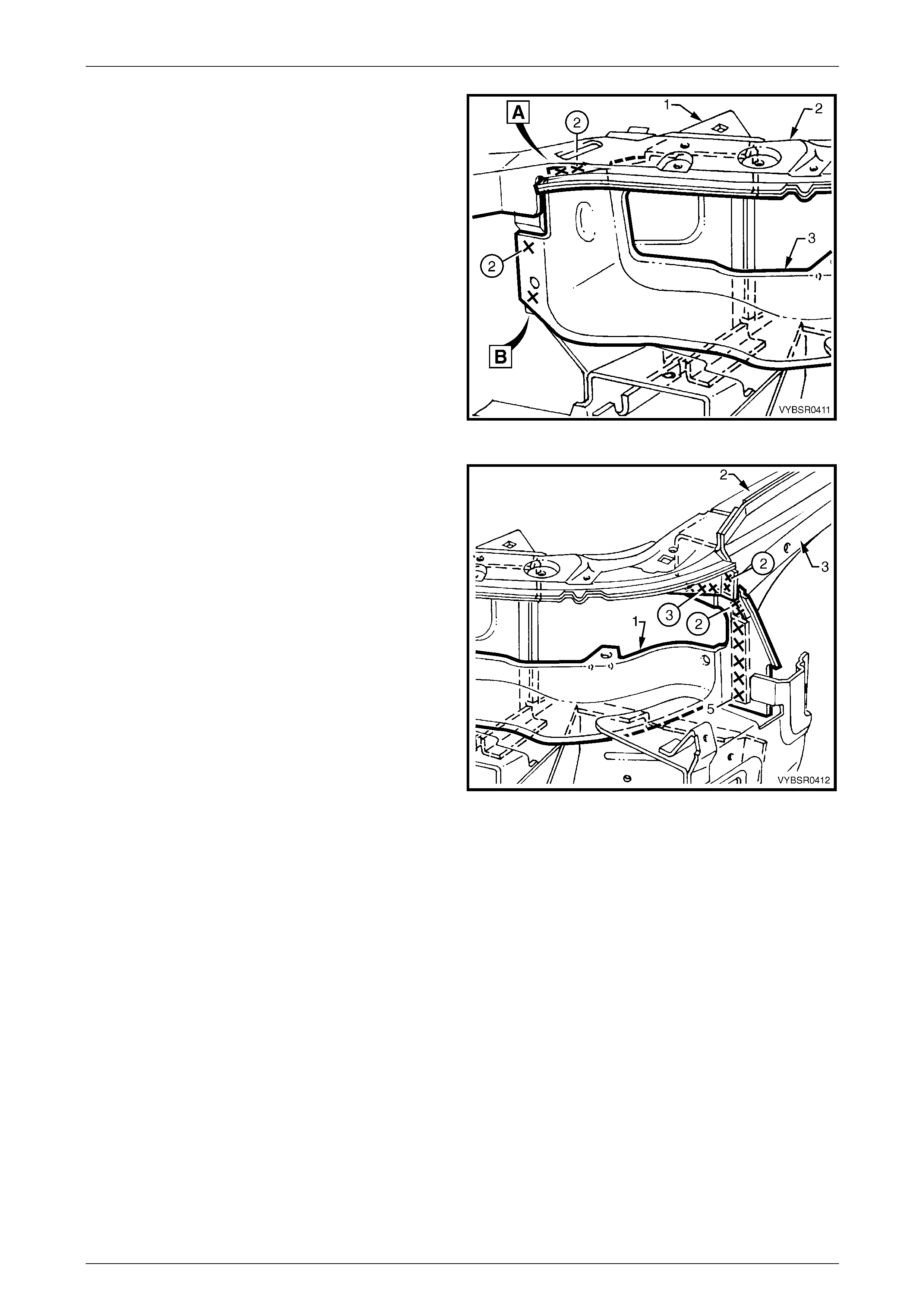
8 On each side of the vehicle, spot cut the welds
attaching the front wheelhouse bracket assembly (1)
to the front end panel upper (2) and headlamp panel
(3).
Figure 4 – 6
9 On each side of the vehicle, spot cut the welds
attaching the headlamp and fr ont fascia mount bracket
(1) and headlamp panel (2) to the front wheelhouse
panel. Refer to weld group A.
10 Spot cut the two welds on each side of the vehicle
attaching the headlamp and fr ont fascia mount bracket
to the front wheelhouse panel bracket (3).
Refer to weld group B.
11 Remove the complete front end panel assembly from
the vehicle and then repair any damage to the
adjacent parts as required.
12 Check and rectify the alignme nt of the bod y as
required, refer to Section 3 Body Construction.
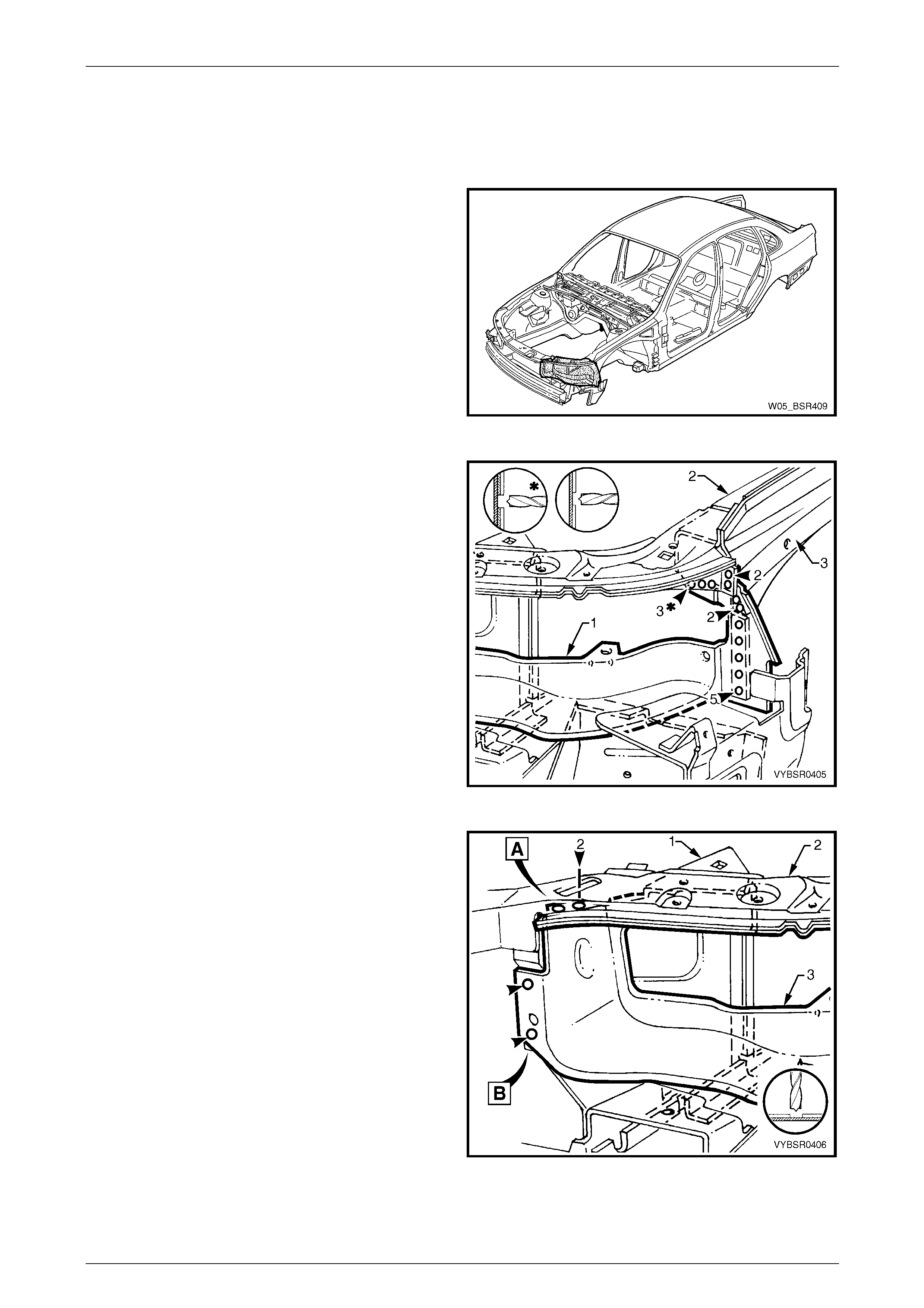
Figure 4 – 7
Replace
NOTE
• Spot welding is the preferred method for
attaching of panels and should be used
whenever possible. Where the spot welding
equipment available will not access the
required weld position, a plug weld should be
performed.
• The same number and position of spot welds
(or plug welds) should be used when
replacing the panel, as was used during
manufacture, in order to maintain the original
structural strength of the vehicle.
1 As required, mark the new panel with drilling locations in preparation for plug welding. Drill holes as req uired.
2 Prepare all mating surfaces and treat with Weld Through Primer (Item 1) as requir ed,
refer to Section 3 Body Construction.
3 Install the panel in position and secure with clamps.
4 Front End Page 4-6
Page 4-6
4 Temporarily install the fenders and hood and check
the alignment and margins.
Refer to Section 3 Body Construction. Adjust where
necessary, and then remove fenders and hood.
Figure 4 – 8
5 Spot weld the headlamp an d front fascia mount
bracket (1) and headlamp panel (2) to the front
wheelhouse panel. Refer to weld group A.
6 Spot weld the headlamp an d front fascia mount
bracket to the front wheelhouse panel bracket (3).
Refer to weld group B.
Figure 4 – 9
7 On each side of the vehicle, spot weld the front
wheelhouse bracket assembly (1) to the front end
panel upper (2) and head lamp panel (3).
Figure 4 – 10
4 Front End Page 4-7
Page 4-7
8 Spot weld in two places on each side of vehicle, the
front wheelhouse bracket assembly (1) to the front end
panel upper (2) and head lamp panel (3).
Refer to weld group A.
9 On each side of the vehicle, spot weld the headlamp
panel and the front end panel upp er to the front
wheelhouse bracket assembly. Refer to weld group B.
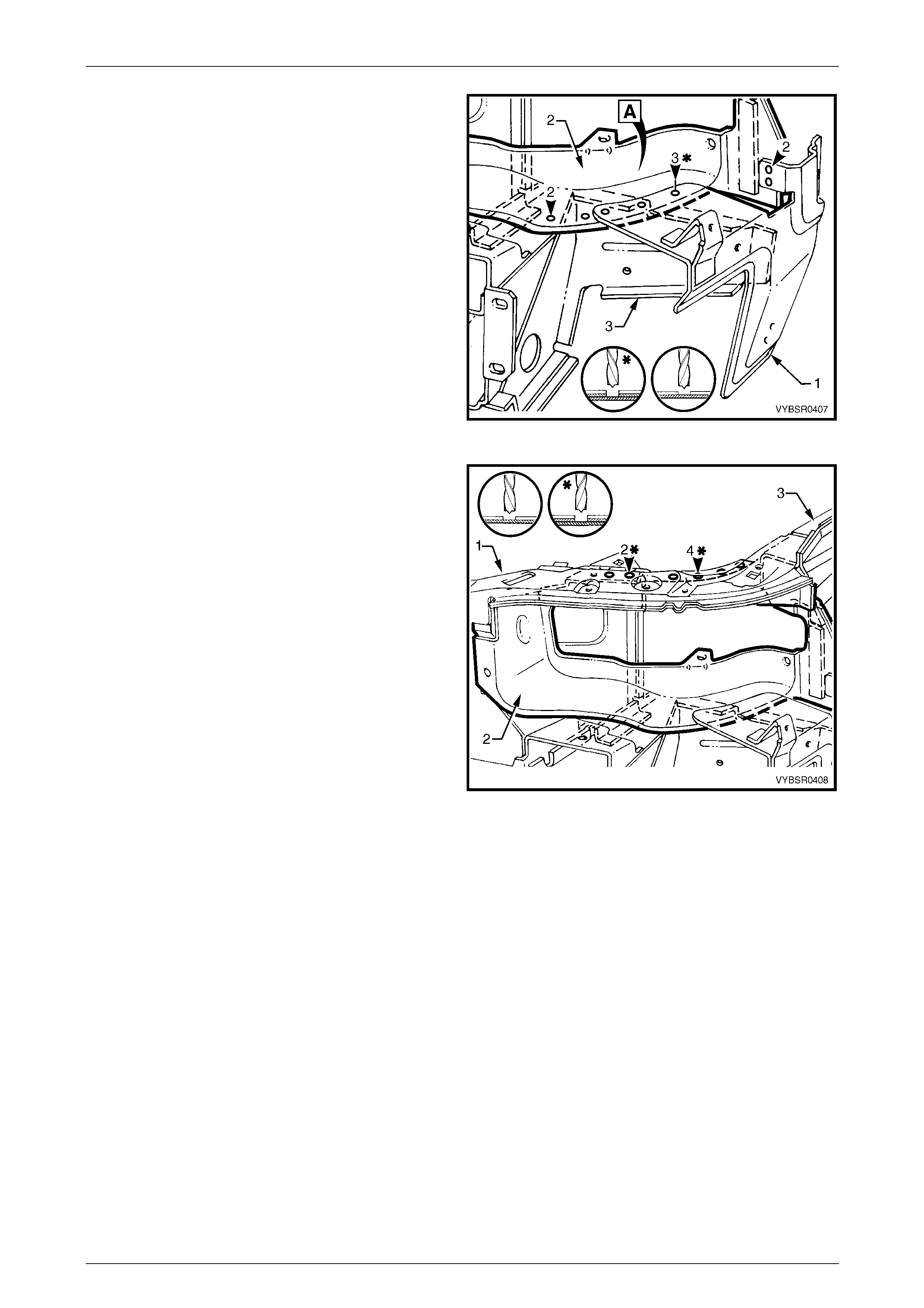
Figure 4 – 11
10 On each side of the vehicle, spot or plug weld the front
end panel upper (1) to the front wheelhouse panel (2).
Four welds are on the horizontal surface and two on
the vertical flange. Refer to weld group A.
11 Weld a total of 10 places on each side of vehicle, the
headlamp panel (3) to the front wheelhouse panel and
the front wheelhouse upper side rail (4).
Refer to weld group B.
12 Refinish and paint panels and other components as
required. Refer to Section 3 Body Construction .
13 Apply Joint Sealer (Item 3) as required.
Refer to Section 3 Body Construction.
14 Apply Cavity Wax (Item 8) as required to the inside of
any box sections or areas inaccessible to paint,
refer to Section 3 Body Construction.
15 Install the front bumper impact bar assembly,
refer to Section 3 Body Construction.
16 Install the remaining components as described in the
appropriate Section of the MY2005 WL Service
Information.
Figure 4 – 12
4 Front End Page 4-8
Page 4-8
2.2 Headlamp Panel – Replace
Remove
1 Remove the adjacent bolt-on panels a nd components
as described in the appropriate Section of the MY2005
WL Service Information.
2 Remove the front bumper impact bar assembly,
refer to Section 3 Body Construction.
Figure 4 – 13
3 Spot cut a total of 12 welds attaching the headlamp
panel (1) to the front wheelhouse pane l (2) and to the
wheelhouse upper side rail (3).
Figure 4 – 14
4 Spot cut the welds attaching the front wheelhouse
bracket assembly (1) to the front end panel upp er (2)
and headlamp panel (3). Refer to weld group A.
5 Spot cut the two welds on the vertical flange attachin g
the headlamp panel to the fro nt end p anel upper and
front wheelhouse bracket assembly.
Refer to weld group B.
Figure 4 – 15
4 Front End Page 4-9
Page 4-9
6 Spot cut the welds attaching the headlamp and front
fascia mount bracket (1) and headlamp pa nel (2) to
the front wheelhouse panel.
Figure 4 – 16
7 Spot cut the welds attaching the front end panel upper
(1) to the headlamp panel (2).
8 Remove the headlamp panel from the vehicle and
then repair any damage to the adjacent parts as
required.
9 Check and rectify the alignme nt of the bod y as
required, refer to Section 3 Body Construction. Repair
any damage to adjacent panels.
Figure 4 – 17
4 Front End Page 4-10
Page 4-10
Replace
NOTE
• Spot welding is the preferred method for
attaching of panels and should be used
whenever possible. Where the spot welding
equipment available will not access the
required weld position, a plug weld should be
performed.
• The same number and position of spot welds
(or plug welds) should be used when
replacing the panel, as was used during
manufacture, in order to maintain the original
structural strength of the vehicle.
1 As required, mark the new panels with drilling locations in preparation for plug welding. Drill holes as req uire d.
2 Prepare all mating surfaces and treat with Weld Through Primer (Item 1) as required,
refer to Section 3 Body Construction.
3 Clamp the headlamp panel in position.
4 Spot or plug weld the front panel upper (1) to the
headlamp panel (2) and to the front fender skirt (3).
Figure 4 – 18
5 Spot weld the headlamp an d front fascia mount
bracket (1) and headlamp panel (2) to the front
wheelhouse panel.
Figure 4 – 19
4 Front End Page 4-11
Page 4-11
6 Spot weld in two places, the front wheelhouse bracket
assembly (1) to the front end panel upper (2) and
headlamp panel (3). Refer to weld group A.
7 Spot weld the headlamp panel and the front end panel
upper to the front wheelhouse bracket assembly.
Refer to weld group B.
Figure 4 – 20
8 Spot weld a total of 12 places, the headlamp panel (1)
to the front wheelhouse panel (2) and the front
wheelhouse upper side rail (3).
9 Refinish and paint panels and other components as
required. Refer to Section 3 Body Construction .
10 Apply Joint Sealer (Item 3) as required.
Refer to Section 3 Body Construction.
11 Apply Cavity Wax (Item 8) as required to the inside of
any box sections or areas inaccessible to paint,
refer to Section 3 Body Construction.
12 Install the front bumper impact bar assembly,
refer to Section 3 Body Construction.
13 Install the remaining components as described in the
appropriate Section of the MY2005 WL Service
Information.
Figure 4 – 21
4 Front End Page 4-12
Page 4-12
2.3 Front Wheelhouse Bracket Assembly,
Front Wheelhouse Bracket and Front
Bumper Impact Bar Bracket Assembly –
Replace
Remove
1 Remove the adjacent bolt-on panels a nd components
as described in the appropriate Section of the MY2005
WL Service Information.
2 Remove the front bumper impact bar assembly,
refer to Section 3 Body Construction.
3 Remove the adjoining panels as required.
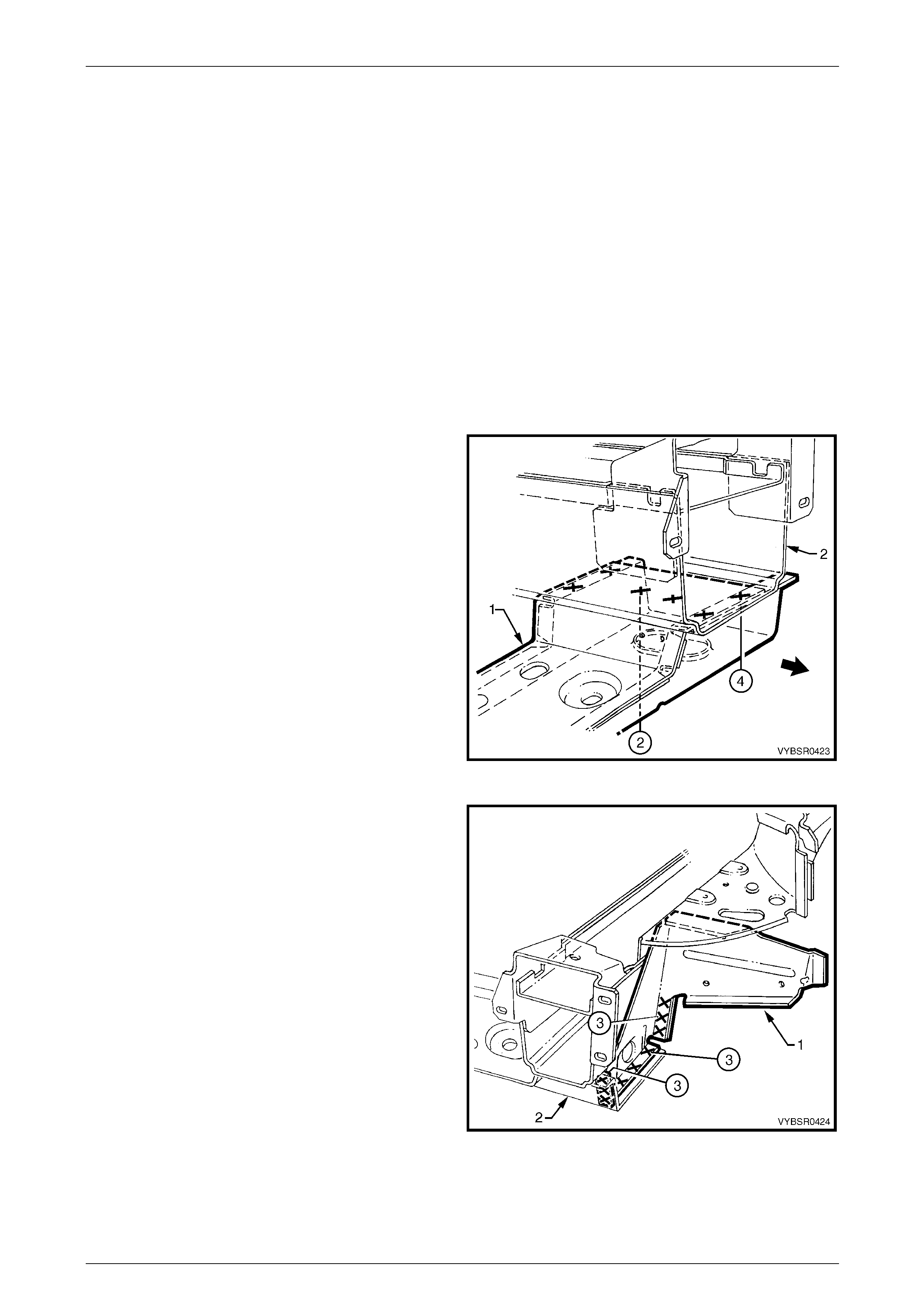
Figure 4 – 22
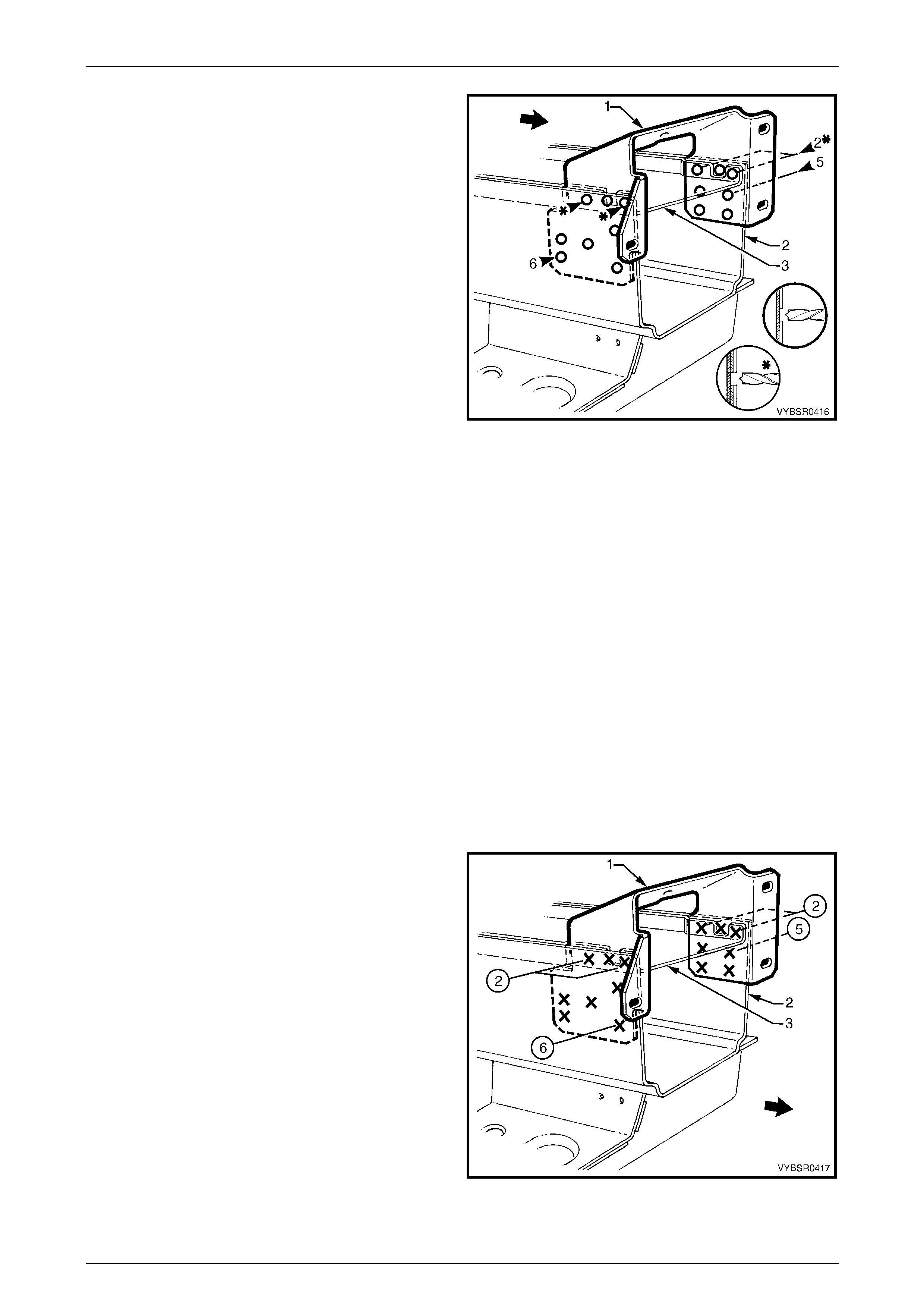
4 Spot cut the six welds attaching the front wheelhouse
bracket assembly (1) to the front side rail (2).
Refer to weld group A.
5 Spot cut the three welds attaching the front
wheelhouse bracket assembly (1) to the front bumper
impact bar bracket (3). Refer to weld group B.
6 Remove the front wheelhouse bracket assembl y.
Figure 4 – 23
7 Spot cut the welds attaching the front wheelhouse
panel bracket (1) to the front side rail (3).
Refer to weld group A.
8 Spot cut the welds attaching the front wheelhouse
panel bracket to the radiator lower support assembly
(2). Refer to weld group B.
9 Spot cut the three welds attaching the front
wheelhouse panel br acket to the front wheelhouse
panel (4). Refer to weld group C.
10 Remove the front wheelhouse panel bracket.
Figure 4 – 24
4 Front End Page 4-13
Page 4-13
11 Spot cut the welds attaching each side of the front
bumper impact bar bracket (1) to the front side rail (2).
12 Prise front bumper impact bar bracket out from
between the front side rail and the front side rail
closing plate (3).
13 Repair any damage to adjacent panels.
14 Check and rectify the alignme nt of the bod y as
required, refer to Section 3 Body Construction.
Figure 4 – 25
Replace
NOTE
• Spot welding is the preferred method for
attaching of panels and should be used
whenever possible. Where the spot welding
equipment available will not access the
required weld position, a plug weld should be
performed.
• The same number and position of spot welds
(or plug welds) should be used when
replacing the panel, as was used during
manufacture, in order to maintain the original
structural strength of the vehicle.
1 As required, mark the new panel with drilling locations in preparation for plug welding. Drill holes as req uired.
2 Prepare all mating surfaces and treat with Weld Through Primer (Item 1) as requir ed,
refer to Section 3 Body Construction.
3 Clamp the panels in position and test fit the front bumper impact bar.
4 Spot weld each side of the front bumper impact bar
mounting bracket (1) to front side rail (2).
Figure 4 – 26
4 Front End Page 4-14
Page 4-14
5 Spot weld the front wheelhouse panel br acket (1) to
the front side rail (3). Refer to weld group A.
6 Spot weld the front wheelhouse panel br acket to the
radiator lower support assembly (2).
Refer to weld group B.
7 Spot weld the front wheelhouse panel br acket to the
front wheelhouse panel (4). Refer to weld group C.
Figure 4 – 27
8 Plug weld the front wheelhouse bracket asse mbly (1)
to the front side rail (2). Refer to weld group A.
9 Spot weld the front wheelhouse bracket assembly to
the front bumper impact bar bracket (3).
Refer to weld group B.
10 Replace the any removed panels as required.
11 Refinish and paint panels and other components as
required. Refer to Section 3 Body Construction .
12 Apply Joint Sealer (Item 3) as required.
Refer to Section 3 Body Construction.
13 Apply Cavity Wax (Item 8) as required to the inside of
any box sections or areas inaccessible to paint,
refer to Section 3 Body Construction.
14 Install the front bumper impact bar assembly,
refer to Section 3 Body Construction.
15 Install the remaining components as described in the
appropriate Section of the MY2005 WL Service
Information. Figure 4 – 28
4 Front End Page 4-15
Page 4-15
2.4 Radiator Lower Support Assembly –
Replace
Remove
1 Remove the adjacent bolt-on panels a nd components
as described in the appropriate Section of the MY2005
WL Service Information.
2 Remove the front bumper impact bar assembly,
refer to Section 3 Body Construction
3 If required, mount the vehicle on a suitable ji g or
secure an appropriate tool between the two front side
rails to maintain correct body alignment when the
radiator lower support assembly is remov ed.
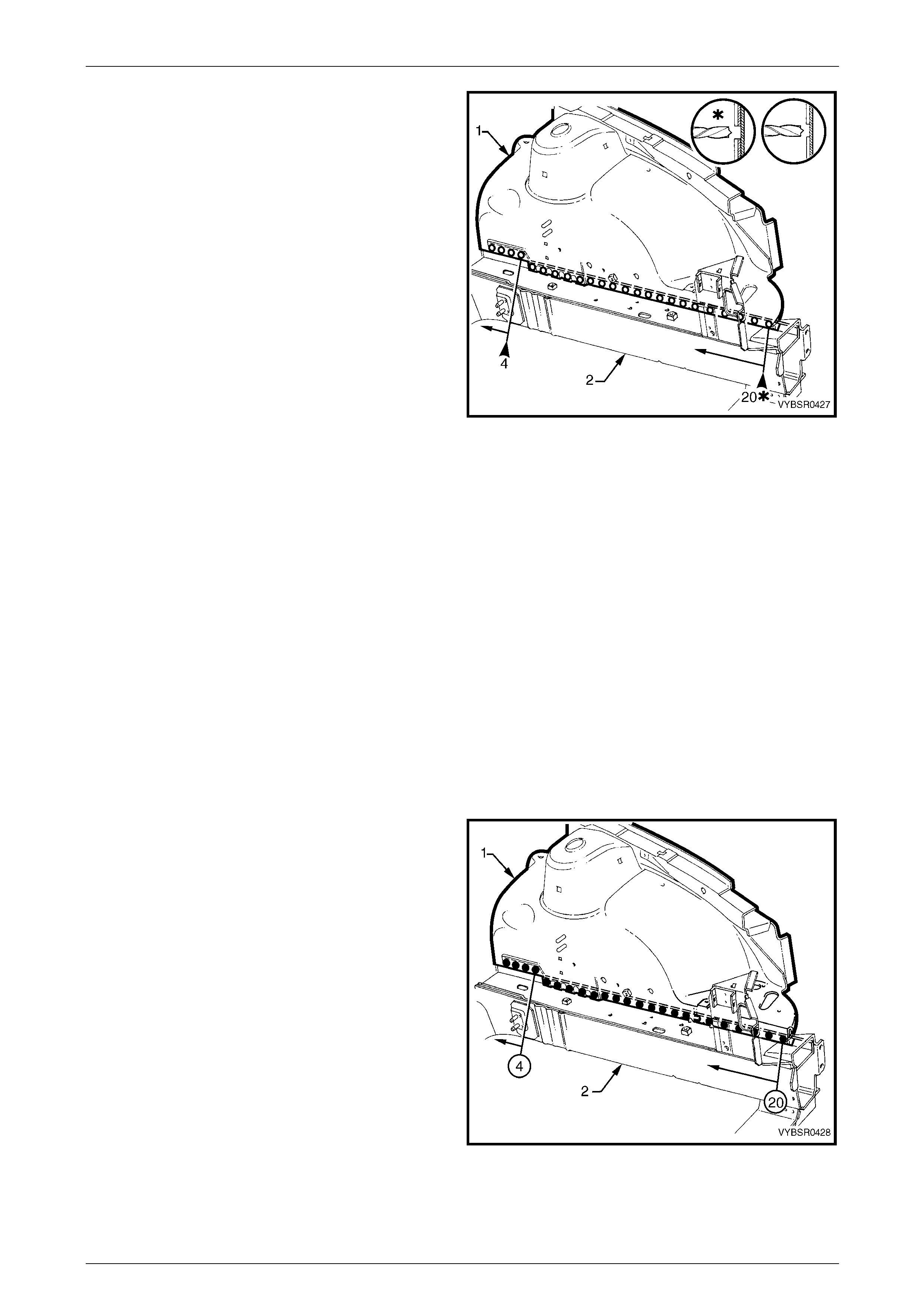
Figure 4 – 29
4 On both sides of the vehicle, spot cut nine welds
attaching the front wheelhouse panel bracket (1) to the
radiator lower support assembly (2).
Figure 4 – 30
5 From underneath the vehicle, spot cut the six welds
attaching the radiator lo wer support assembly (1) to
each front side rail (2).
NOTE
Access is available to the two centre spot welds
through the hole on the under side of the support.
6 Remove the radiator lower support assembly from the
vehicle.
Figure 4 – 31
4 Front End Page 4-16
Page 4-16
Replace
NOTE
• Spot welding is the preferred method for
attaching of panels and should be used
whenever possible. Where the spot welding
equipment available will not access the
required weld position, a plug weld should be
performed.
• The same number and position of spot welds
(or plug welds) should be used when
replacing the panel, as was used during
manufacture, in order to maintain the original
structural strength of the vehicle.
1 As required, mark the new panel with drilling locations in preparation for plug welding. Drill holes as req uired.
2 Prepare all mating surfaces and treat with Weld Through Primer (Item 1) as requir ed,
refer to Section 3 Body Construction.
3 Clamp the radiator lower support assembly (1) in
position on the front side rails (2) and spot or plug
weld in place.
Figure 4 – 32
4 Spot weld nine places, the front wheelhouse panel
bracket (1) to the radiator lower support assembly (2).
5 Refinish and paint panels and other components as
required. Refer to Section 3 Body Construction .
6 Apply Joint Sealer (Item 3) as required.
Refer to Section 3 Body Construction.
7 Apply Cavity Wax (Item 8) as required to the inside of
any box sections or areas inaccessible to paint,
refer to Section 3 Body Construction.
8 Install the front bumper impact bar assembly,
refer to Section 3 Body Construction.
9 Install the remaining components as described in the
appropriate Section of the MY2005 WL Service
Information.
Figure 4 – 33
4 Front End Page 4-17
Page 4-17
2.5 Front Wheelhouse Panel Upper Side Rail
– Replace
Remove
1 Remove the adjacent bolt-on panels a nd components
as described in the appropriate Section of the MY2005
WL Service Information.
2 Remove the front bumper impact bar assembly,
refer to Section 3 Body Construction.
3 As required, remove front end pane l assembly or spot
cut the welds attaching the side rail to the front end
panel assembly,
refer to 2.1 Front End Panel Assembly – Replace.
Figure 4 – 34
4 Spot cut the welds attaching the front wheelhouse
panel upper side rail (1) to the door ope nin g frame
assembly (2), hinge pillar inner panel assembly (3)
and front wheelhouse panel assembly (4) and remove
the upper side rail.
Figure 4 – 35
4 Front End Page 4-18
Page 4-18
Replace
NOTE
• Spot welding is the preferred method for
attaching of panels and should be used
whenever possible. Where the spot welding
equipment available will not access the
required weld position, a plug weld should be
performed.
• The same number and position of spot welds
(or plug welds) should be used when
replacing the panel, as was used during
manufacture, in order to maintain the original
structural strength of the vehicle.
1 As required, mark the new panel with drilling locations in preparation for plug welding. Drill holes as req uired.
2 Prepare all mating surfaces and treat with Weld Through Primer (Item 1) as requir ed,
refer to Section 3 Body Construction.
3 Clamp the front wheelhouse pane l upper side rail in position.
4 Spot or plug weld the front wheelhouse panel upper
side rail (1) to the door opening frame assembly (2),
hinge pillar inner panel assembly (3) and front
wheelhouse panel ass embly (4).
5 As required, replace the front end pan el asse mbly or
spot or plug weld the side rail to the front end panel
assembly,
refer to 2.1 Front End Panel Assembly – Replace.
6 Refinish and paint panels and other components as
required. Refer to Section 3 Body Construction .
7 Apply Joint Sealer (Item 3) as required.
Refer to Section 3 Body Construction
8 Apply Cavity Wax (Item 8) as required to the inside of
any box sections or areas inaccessible to paint,
refer to Section 3 Body Construction).
Figure 4 – 36
9 Apply Spray-on Dea de ner (Item 7) to the wheel side of
front wheelhouse panel assembly.
Refer to Section 3 Body Construction.
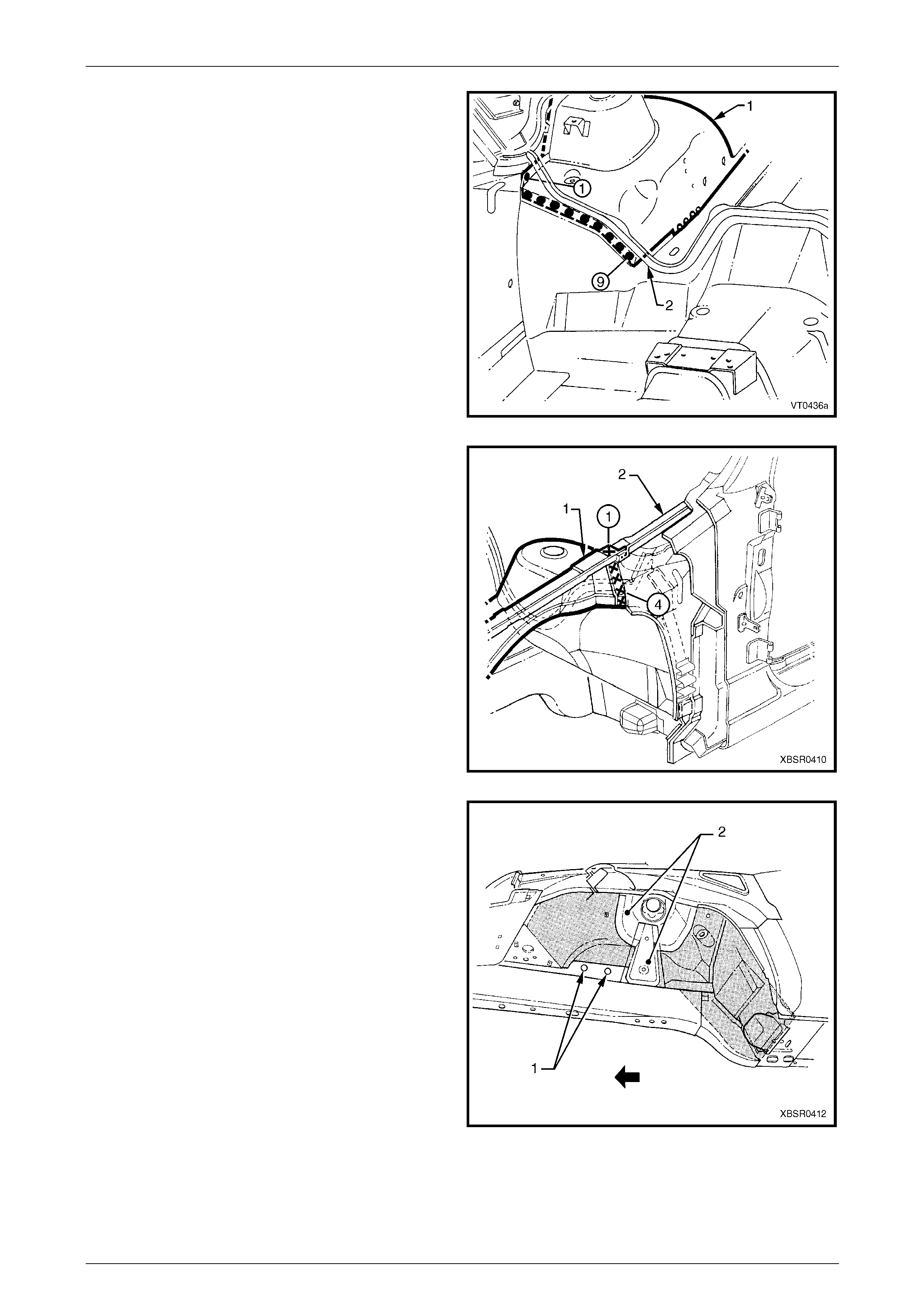
NOTE
Keep the area around brake pipe holes ( 1) clear
of deadener. Overspray of deadener is
permissible on the strut tower reinforcement and
front suspension strut tower (2).
10 Install the front bumper impact bar assembly,
refer to Section 3 Body Construction.
11 Install the remaining components as described in the
appropriate Section of the MY2005 WL Service
Information.
Figure 4 – 37
4 Front End Page 4-19
Page 4-19
2.6 Front Wheelhouse Panel Assembly –
Replace
Remove
1 Remove the adjacent bolt-on panels a nd components
as described in the appropriate Section of the MY2005
WL Service Information.
2 Remove the front bumper impact bar assembly,
refer to Section 3 Body Construction.
3 If required, mount the vehicle on a suitable ji g or
secure an appropriate tool between the front side rails
to maintain correct body alig nment when the front end
panel assembly is removed.
4 Remove front end panel assembly,
refer to 2.1 Front End Panel Assembly – Replace.
5 Remove the welds attaching the front wheelhouse
panel bracket to the front wheelhouse, refer to
2.3 Front Wheelhouse Bracket Assembly, Front
Wheelhouse Bracket and F ront Bumper Impact Bar
Bracket Assembly – Replace.
6 Remove the front wheelhouse pan el upper side rail,
refer to 2.5 Front Wheelhouse Panel Upper Side Rail
– Replace.
Figure 4 – 38
7 Spot cut the welds attaching the front wheelhouse
panel assembly (1) to the hinge pillar inner panel
assembly (2).
Figure 4 – 39
8 Spot cut the welds attaching the front wheelhouse
panel assembly (1) to the front floor panel extension
(2). NOTE
The dash panel assembly is not shown for
clarity.
9 Spot cut the weld attaching the front wheelhouse
panel assembly (1) to the hinge pillar inner panel
assembly.
Figure 4 – 40
4 Front End Page 4-20
Page 4-20
10 Spot cut the welds attaching the front wheelhouse
panel assembly (1) to the front side rail (2).
11 Remove front wheelhouse panel assembly and repair
any adjacent damaged panels as required.
12 Check and rectify the alignme nt of the bod y as
required, refer to Section 3 Body Construction.
Figure 4 – 41
Replace
NOTE
• Spot welding is the preferred method for
attaching of panels and should be used
whenever possible. Where the spot welding
equipment available will not access the
required weld position, a plug weld should be
performed.
• The same number and position of spot welds
(or plug welds) should be used when
replacing the panel, as was used during
manufacture, in order to maintain the original
structural strength of the vehicle.
1 As required, mark the new panel with drilling locations in preparation for plug welding. Drill holes as req uired.
2 Prepare all mating surfaces and treat with Weld Through Primer (Item 1) as requir ed,
refer to Section 3 Body Construction.
3 Clamp the front wheelhouse pane l assembly in position and confirm its location by checking the vehicle body
dimensions, refer to Section 3 Body Construction. Additionally, the front fender and engine hood may be fitted to
confirm margins.
4 Plug weld the front wheelhouse pan el assembly (1) to
the front side rail (2).
Figure 4 – 42
4 Front End Page 4-21
Page 4-21
5 Plug weld the front wheelhouse pan el assembly (1) to
the front floor panel extension (2) and the hinge pillar
inner panel assembly.
Figure 4 – 43
6 Spot weld the front wheelhouse panel ass embly (1) to
the hinge pillar inner panel assembly (2).
7 Replace the front wheelhouse panel upper side rail,
refer to 2.5 Front Wheelhouse Panel Upper Side Rail
– Replace.
8 Replace the front end panel assembly, refer to
2.1 Front End Panel Assembly – Replace.
9 Refinish and paint panels and other components as
required. Refer to Section 3 Body Construction .
10 Apply Joint Sealer (Item 3) as required.
Refer to Section 3 Body Construction.
11 Apply Cavity Wax (Item 8) as required to the inside of
any box sections or areas inaccessible to paint,
refer to Section 3 Body Construction.
Figure 4 – 44
12 Apply Spray-on Dea de ner (Item 7) to the wheel side of
front wheelhouse panel assembly.
Refer to Section 3 Body Construction.
NOTE
Keep the area around brake pipe holes ( 1) clear
of deadener. Overspray of deadener is
permissible on the strut tower reinforcement and
front suspension strut tower (2).
13 Install the front bumper impact bar assembly,
refer to Section 3 Body Construction.
14 Install the remaining components as described in the
appropriate Section of the MY2005 WL Service
Information.
Figure 4 – 45
4 Front End Page 4-22
Page 4-22
2.7 Front Wheelhouse Panel and Front Side
Rail – Partial Replace
Remove
If significant creasing or crumple of the front
side rail has occurred an d continues rearw ard
of the front su spension crossmember, the fu ll
front side rail assembly must be replaced.
Refer to 1 General Description for further
information.
NOTE
The integrity of the front side rails is critical t o the
function of the occupant protection system. If the
rails are incorrectly repaired following damage, it
is possible the occupant protection system will
not function as intended, allowing incorrect
deployment.
1 Remove the adjacent bolt-on panels a nd components
as described in the appropriate Section of the MY2005
WL Service Information.
2 Remove the front bumper impact bar assembly,
refer to Section 3 Body Construction.
3 Either mount the vehicle on a suitable jig or secure a n
appropriate tool between the front side rails to
maintain correct body alignment when the front end
panel assembly is removed.
4 Remove the front end panel assembly,
refer to 2.1 Front End Panel Assembly – Replace.
Figure 4 – 46
5 Remove the front wheelhouse pan el upper side rail on the damaged si de,
refer to 2.5 Front Wheelhouse Panel Upper Side Rail – Replace.
6 Either detach one side, or remove completely, the radiator lower support assembly,
refer to 2.4 Radiator Lower Support Assembly – Replace.
7 If the damage is on the right-hand si de of the vehicle,
the front wheelhouse panel will be cut through the
position of the multiuse relay housing bracket and
brake pressure modulator bracket assembly.
In this case, remove the brackets, refer to
2.9 Brake Pressure Modulator Bracket Assembly and
Multiuse Relay Housing Bracket.
Figure 4 – 47
4 Front End Page 4-23
Page 4-23
8 Rough cut the damaged front wheelh ouse panel and
front side rail, leaving enough material to allow the
final cut lines to be completed.
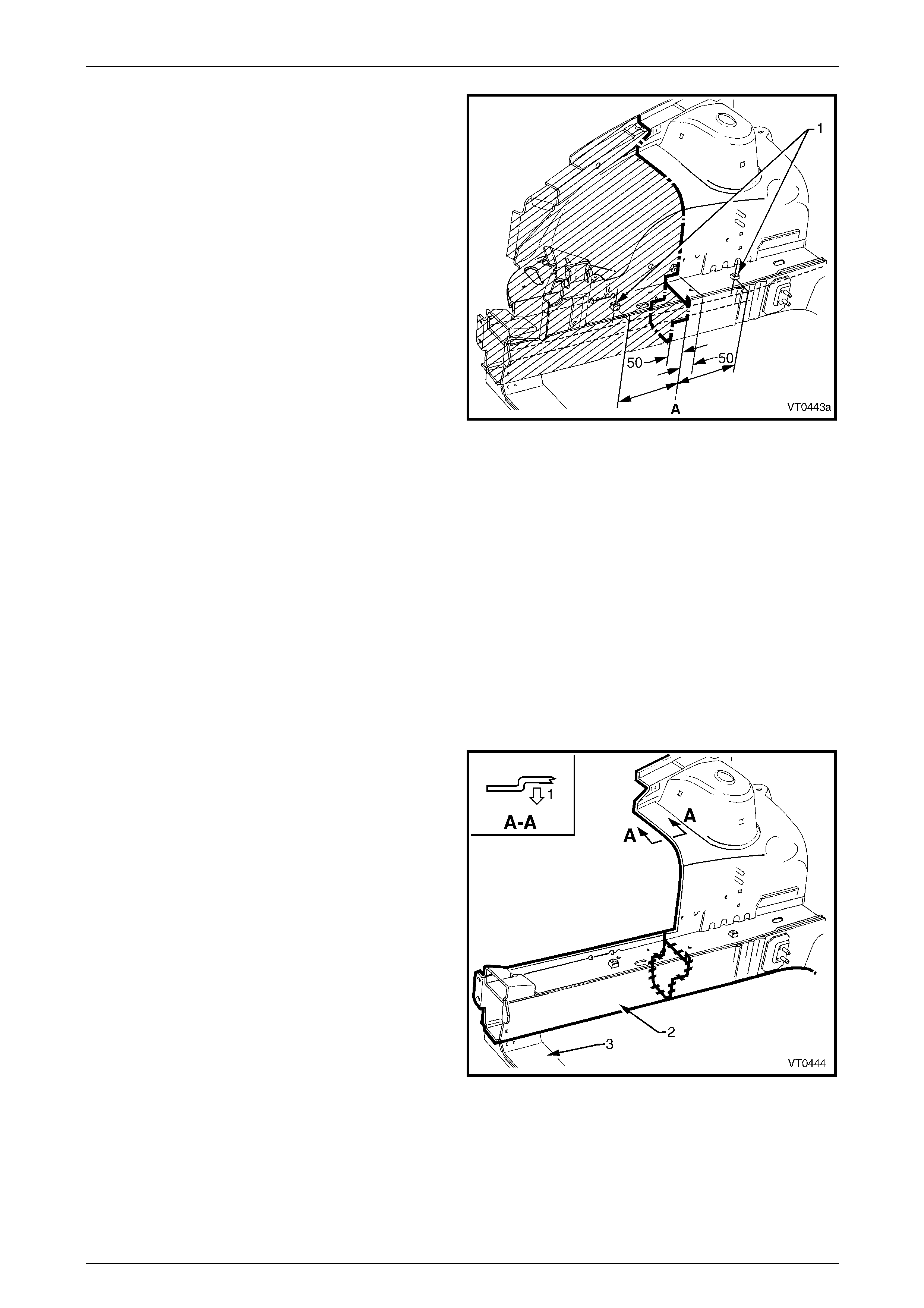
9 Cut the front side rail half way through its depth, mid
way between the two crossmember mounting bolt
holes shown A.
10 Step the cut forward by 50 mm as shown, so that the
load is not concentrated through a singl e lin e.
11 Accurately trim the front wheelhouse panel, 50 mm
rearward of the top front side rail cut.
12 Repair any damage to adjacent areas.
13 Check and rectify the alignme nt of the bod y as
required, refer to Section 3 Body Construction.
Figure 4 – 48
Replace
NOTE
• Spot welding is the preferred method for
attaching of panels and should be used
whenever possible. Where the spot welding
equipment available will not access the
required weld position, a plug weld should be
performed.
• The same number and position of spot welds
(or plug welds) should be used when
replacing the panel, as was used during
manufacture, in order to maintain the original
structural strength of the vehicle.
1 Using a suitable tool, modify the edge of the remaining
section of the front wheelhouse panel to form a joggle,
to facilitate lap jointing. T he joggle should be towards
the outside of the vehicle (1).
2 Accurately step cut the required section (2) from a new
front side rail assembly and clamp or tack weld the
new section in position.
3 Clamp the radiator lower support (3) in position.
Ensure the alignment of the front side rail and lower
support is correct,
refer to Section 3 Body Construction.
4 Butt-weld the stepped longitudinal sections together.
The weld should extend arou nd the entire peripher y of
the cut.
5 Spot or plug weld the radiator lower support (3) in
place. Refer to 2.4 Radiator Lower Support Assembly
– Replace.
Figure 4 – 49
4 Front End Page 4-24
Page 4-24
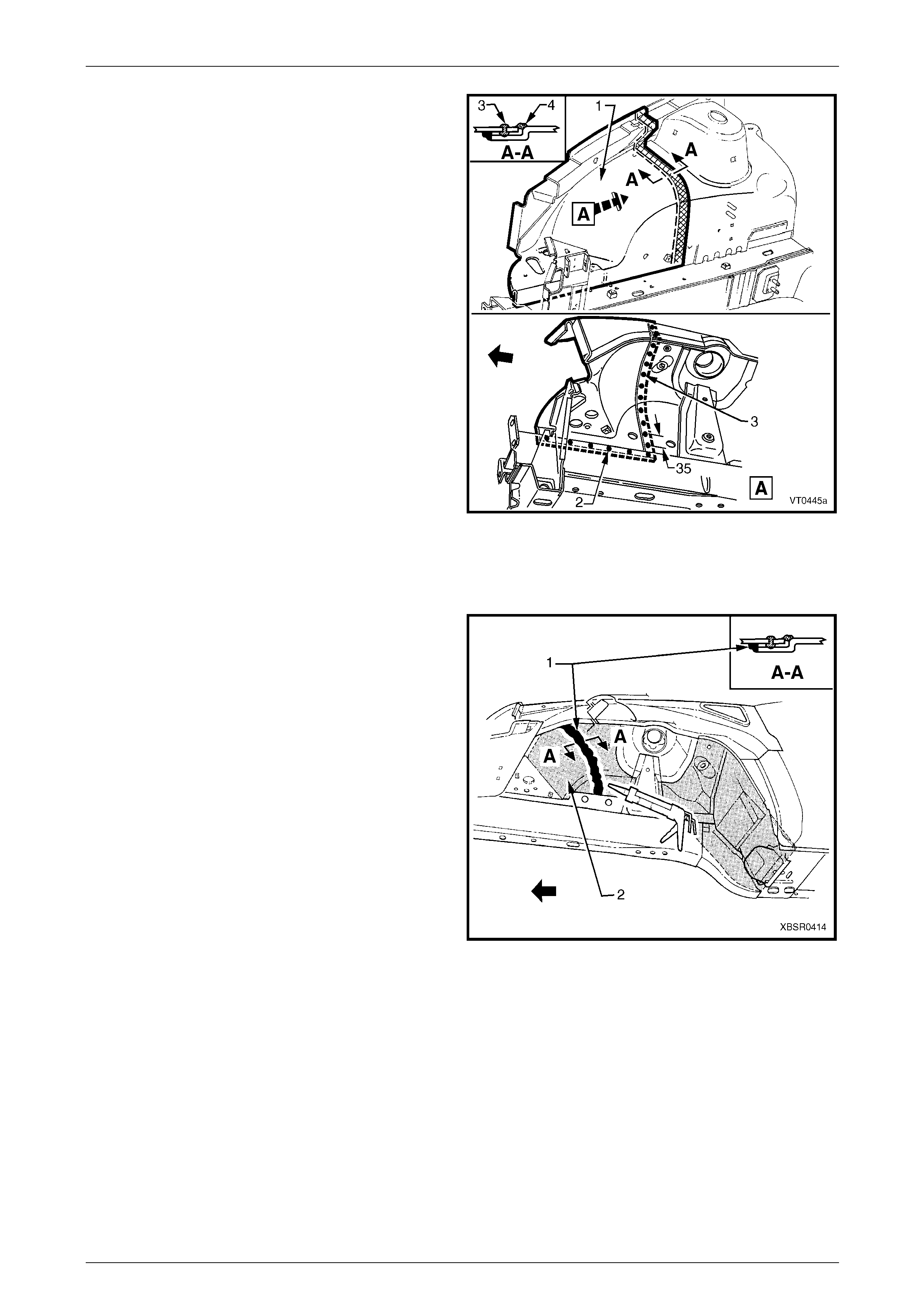
6 Accurately cut the required section (1) from a new
front wheelhouse panel assembly to replace the
removed section.
7 Drill the required holes in the lower edge of the front
wheelhouse panel to perm it plug welding to the front
side rail.
8 Drill holes along the lap j oint approximately every
25 mm, to accommodate plug welding of the joint.
9 Prepare all mating surfaces and treat with Weld
Through Primer (Item 1) as required,
refer to Section 3 Body Construction.
10 Clamp the modified front wheelhouse panel in position
and plug weld (2) to the front side rail.
11 Plug weld along the lap joi nt (3) throug h the previously
drilled holes.
12 Additionally, MIG (fillet) weld the front wheelhouse
panel sections together on the engine compartment
side (4).
13 Dress the welds on the engine compartment side with
a suitable grinder or sander, removing the mi nimum
amount of weld consistent with achieving an
acceptable surface finish. Figure 4 – 50
15 Install the front wheelhouse panel upper side rail, refer to 2.5 Front Wheelho use Panel Upper Side Rail – Replace.
16 Install the front end panel ass embl y, refer to 2.1 F r ont End Panel Assembly – Replace.
17 Seal the wheel side of the seam with Joint Sealer
(Item 3) (1) and apply Spray-on Deadener (Item 7) (2)
to the wheel side of the front wheelhouse panel
assembly, refer to Section 3 Body Construction.
18 Refinish and paint panels and other components as
required. Refer to Section 3 Body Construction .
19 Apply Joint Sealer (Item 3) as required.
Refer to Section 3 Body Construction.
Figure 4 – 51
20 Apply Cavity Wax (Item 8) as required to the inside of any box secti ons or areas inaccessible to paint,
refer to Section 3 Body Construction.
21 Install the front bumper impact bar assembly, refer to Section 3 Body Construction.
22 Install the remaining components as described in the appropriate Section of the MY2005 WL Service Information.
4 Front End Page 4-25
Page 4-25
2.8 Front Side Rail Assembly– Replace
Remove
The integrity of the front side rails is critical to
the function of the occupant protection
system. If the rails are incorrectly repaired
following damage, it is possible the occupant
protection and airbag system will not function
as intended, allowing incorrect deployment.
Refer to 1 General Description for further
information
1 Remove the adjacent bolt-on panels a nd components
as described in the appropriate Section of the MY2005
WL Service Information.
2 Remove the front bumper impact bar assembly,
refer to Section 3 Body Construction.
3 Secure the vehicle on a suitab le fixture ensuring that it
is mounted without relying on support from the front
side rail assembly(s) being replaced.
Figure 4 – 52
4 Remove the front end panel assembly as required, refer to 2.1 Front End Panel Assembly – Replace.
5 Remove the radiator lower support assembly as required,
refer to 2.4 Radiator Lower Support Assembly – Replace.
6 Remove the front wheelhouse pan el assembly as required,
refer to 2.6 Front Wheelhouse Panel Assembly – Replace.
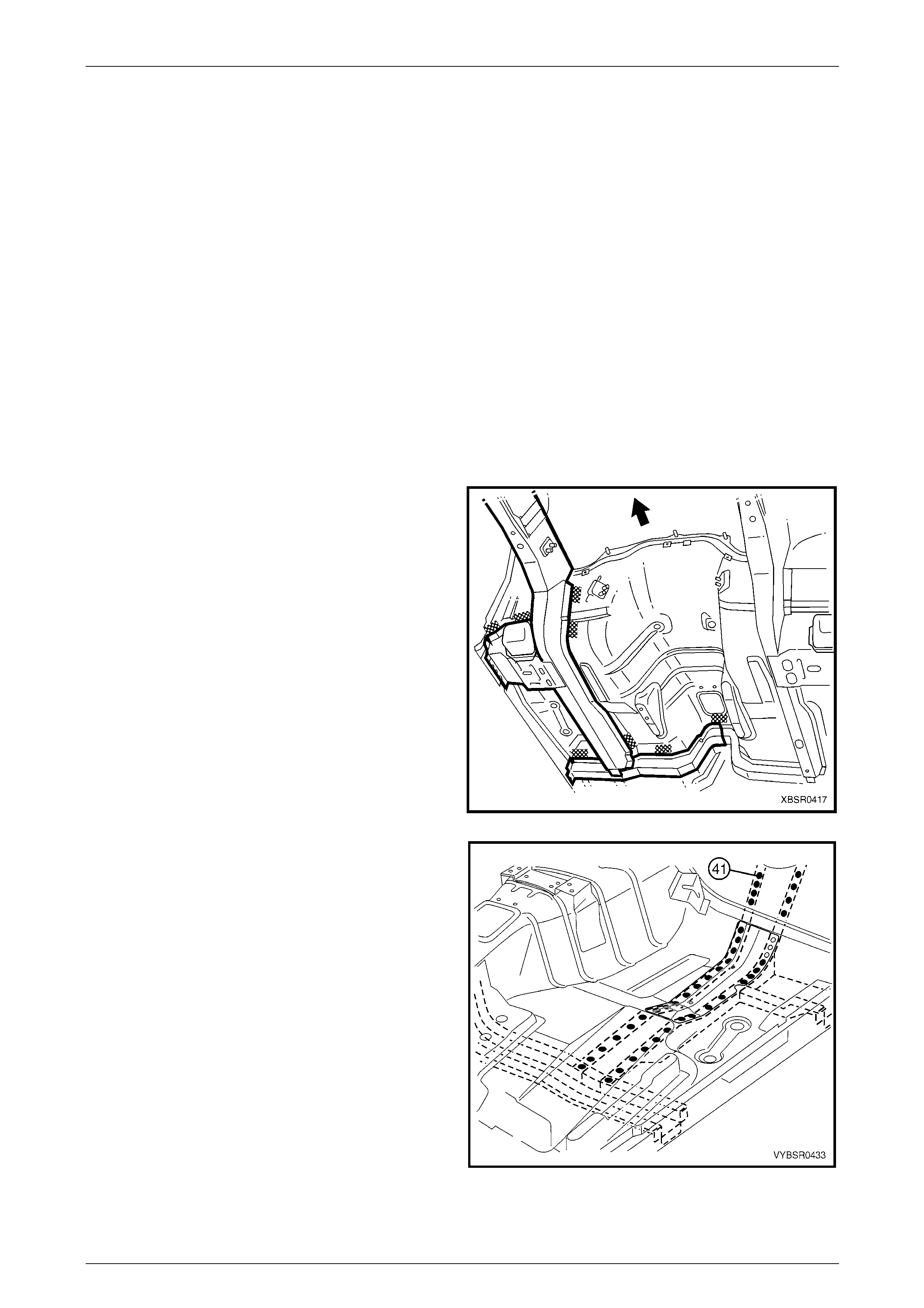
7 Using a scraper and heat gun, remove the body sealer and deadener from the front floor and floor extension in the
front side rail attaching areas.
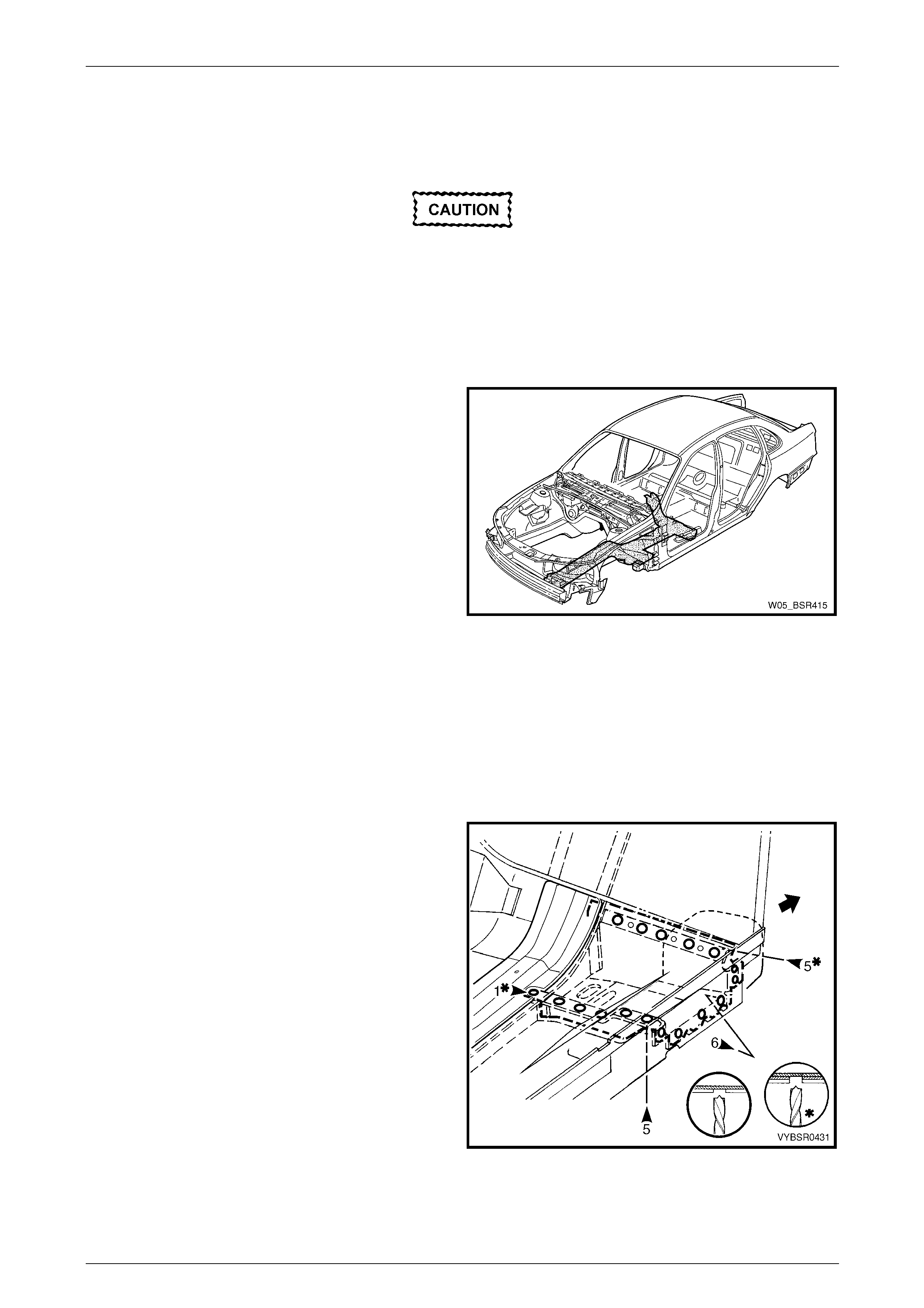
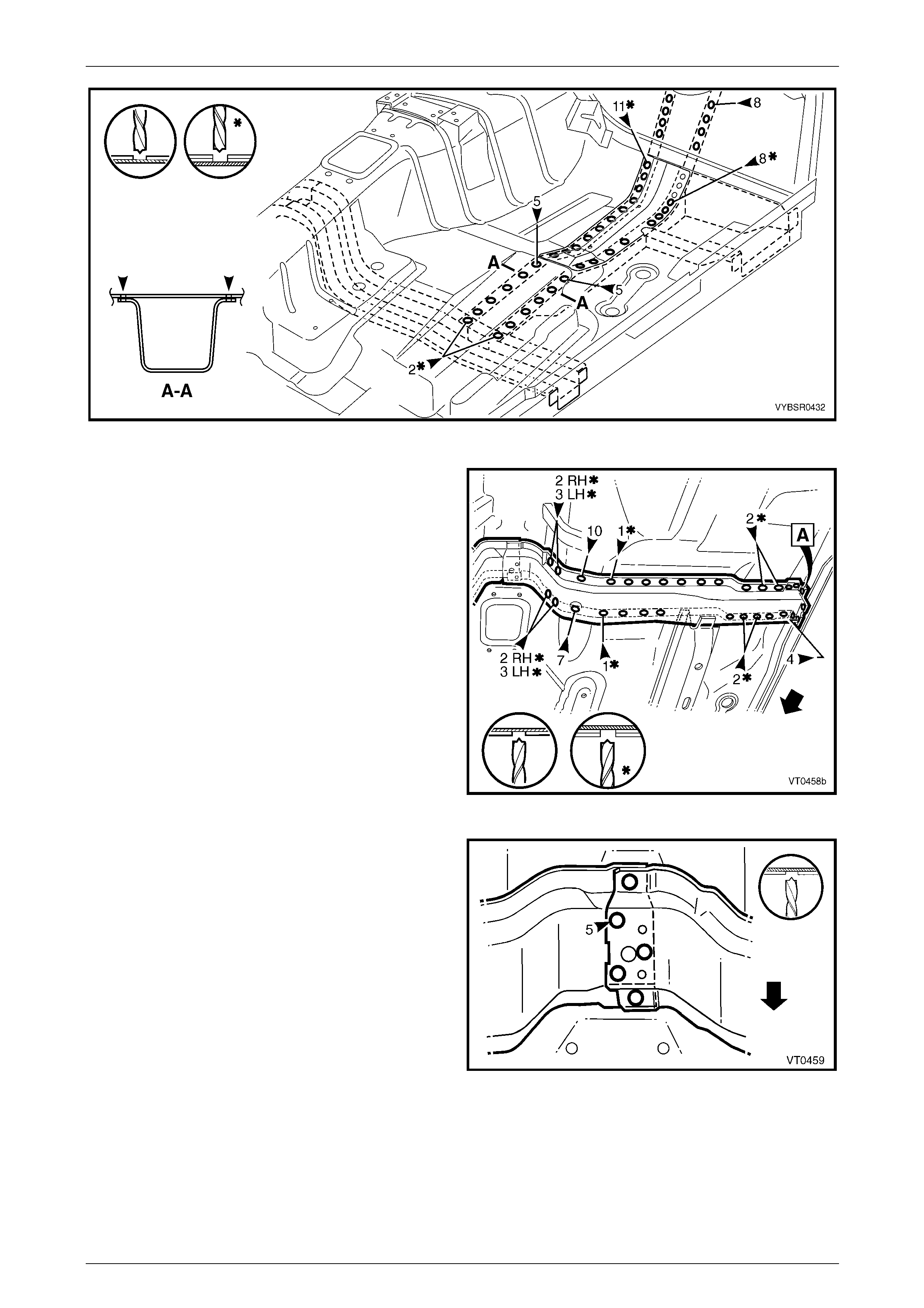
8 Spot cut the welds attaching the front floor panel
support assembly to the front floor panel and inner
rocker panel.
9 Spot cut the welds attaching the front side rail
assembly to the front floor extension panel and front
floor panel, refer to Figure 4 – 54.
Figure 4 – 53
4 Front End Page 4-26
Page 4-26
Figure 4 – 54
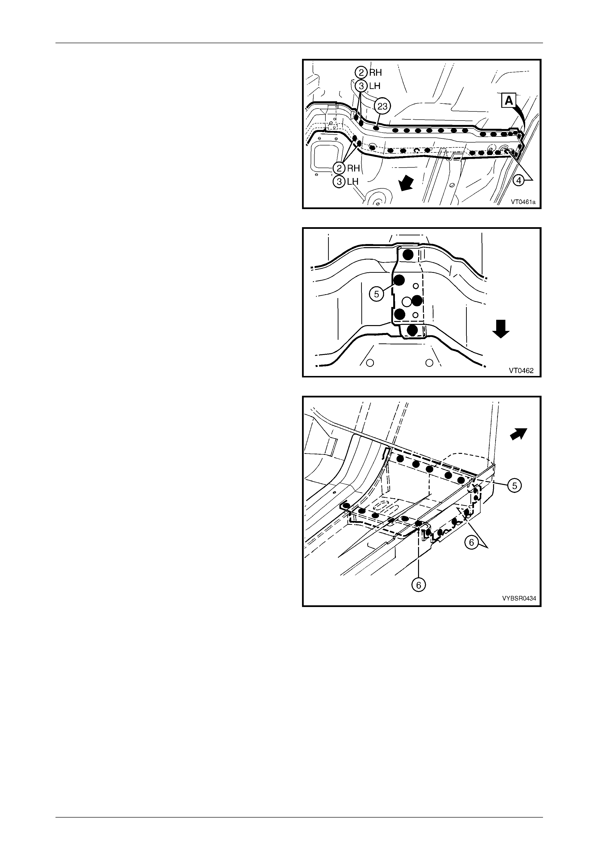
10 Spot cut four welds attaching the centre crossmember
to the inner rocker panel. Refer to weld group A.
11 Spot cut the welds attaching the centre crossmember
to the front floor panel and seat inner br acket
assembly.
Figure 4 – 55
12 Spot cut five welds attaching the right-hand centre
crossmember to the left-hand centre crossmember.
13 Remove the front side rail assembly from the vehicle
and repair any damage to adjoining ar eas.
14 Check and rectify the alignme nt of the bod y as
required, refer to Section 3 Body Construction.
Figure 4 – 56
4 Front End Page 4-27
Page 4-27
Replace
NOTE
• Spot welding is the preferred method for
attaching of panels and should be used
whenever possible. Where the spot welding
equipment available will not access the
required weld position, a plug weld should be
performed.
• The same number and position of spot welds
(or plug welds) should be used when
replacing the panel, as was used during
manufacture, in order to maintain the original
structural strength of the vehicle.
1 Dress the floor in the areas where the front side rail assemb ly will attach and mark the new assembly with drilling
locations in preparation for plug welding. Drill holes as req uired.
2 Prepare all mating surfaces and treat with Weld Through Primer (Item 1) as required,
refer to Section 3 Body Construction.
3 Secure the new front side rail assembly in positio n on the vehicle and clamp the radiator lower support assembly in
place.
4 Check the alignment of the front side rail assembl y, refer to Section 3 Bo dy Construction.
5 Lightly tack weld the front side rail assembly to the
floor in a few places, then recheck the align m ent as
above. Correct as required.
Figure 4 – 57
6 Plug weld the front side rail assembly to the front floor
panel extension and front floor panel.
Figure 4 – 58
4 Front End Page 4-28
Page 4-28
7 Plug weld the centre crossmember to the inner rocker
panel, refer to weld group A and to the front floor
panel.
Figure 4 – 59
8 Plug weld in four places, the right-hand centre
crossmember to the left-hand centre crossmember.
Figure 4 – 60
9 Plug or spot weld the front floor panel support
assembly to the front floor panel and inner rocker
panel.
10 Reinstall the radiator lower support assembly, refer to
2.4 Radiator Lower Support Assembly – Replace.
11 Install the front wheelhouse panel assembly, refer to
2.6 Front Wheelhouse Pane l Assembly – Replace.
12 Install the front end panel ass embl y, refer to
2.1 Front End Panel Assembly – Replace.
13 Refinish and paint panels and other components as
required. Refer to Section 3 Body Construction .
14 Apply Joint Sealer (Item 3) as required.
Refer to Section 3 Body Construction.
15 Apply Cavity Wax (Item 8) as required to the inside of
any box sections or areas inaccessible to paint,
refer to Section 3 Body Construction.
16 Apply Spray-on Deadener (Item 7), after the
application of body colour.
Refer to Section 3 Body Construction. Figure 4 – 61
17 Install the front bumper impact bar assembly, refer to Section 3 Body Construction.
18 Install the remaining components as described in the appropriate Section of the MY2005 WL Service Information.
4 Front End Page 4-29
Page 4-29
2.9 Brake Pressure Modulator Bracket
Assembly and Multiuse Relay Housing
Bracket
Remove
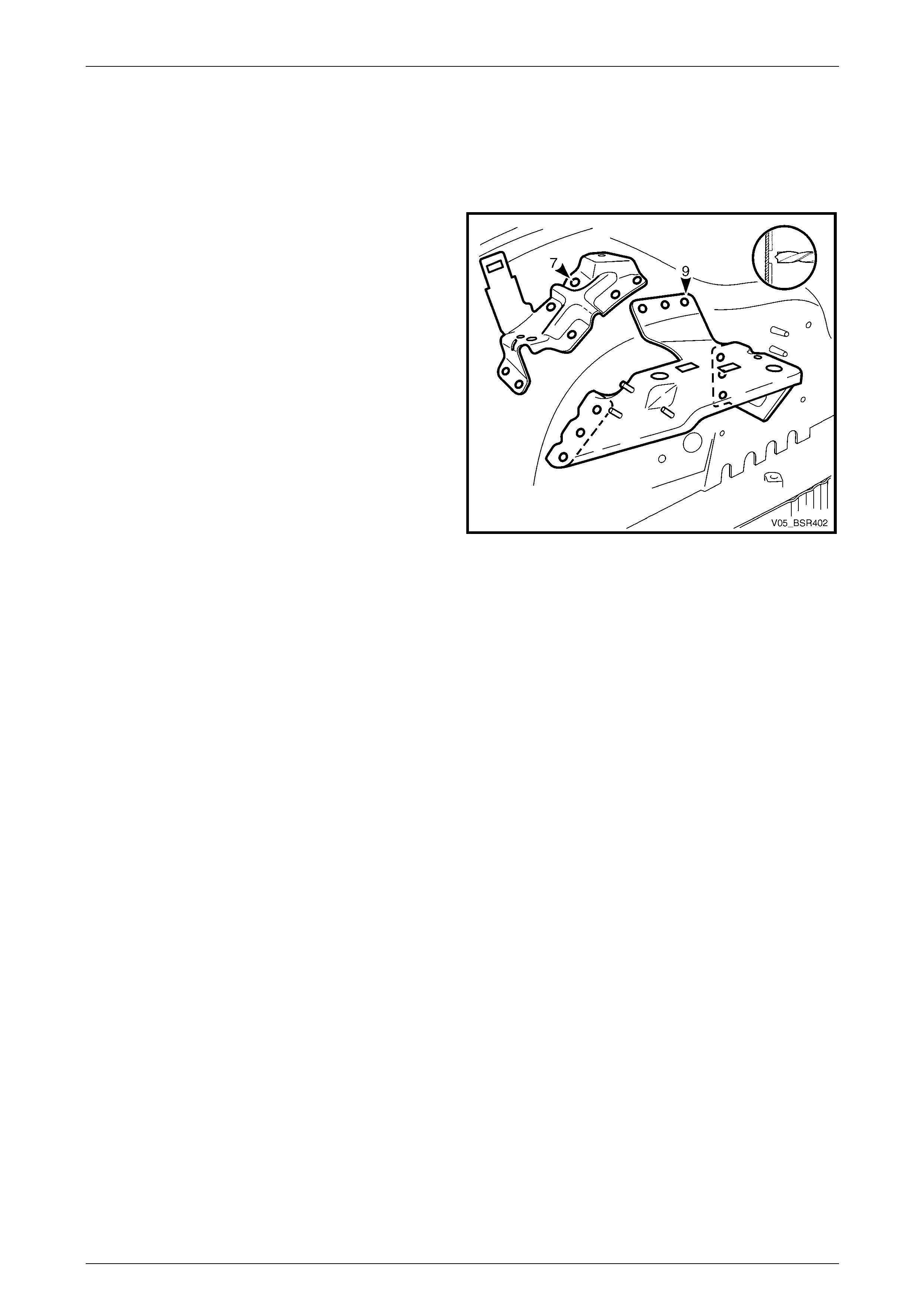
1 Spot cut the nine welds attaching the brake pressure
modulator bracket assembly or the seven welds
attaching the multiuse relay housing bracket to the
front wheelhouse panel.
Figure 4 – 62
Replace
NOTE
• Spot welding is the preferred method for
attaching of panels and should be used
whenever possible. Where the spot welding
equipment available will not access the
required weld position, a plug weld should be
performed.
• The same number and position of spot welds
(or plug welds) should be used when
replacing the panel, as was used during
manufacture, in order to maintain the original
structural strength of the vehicle.
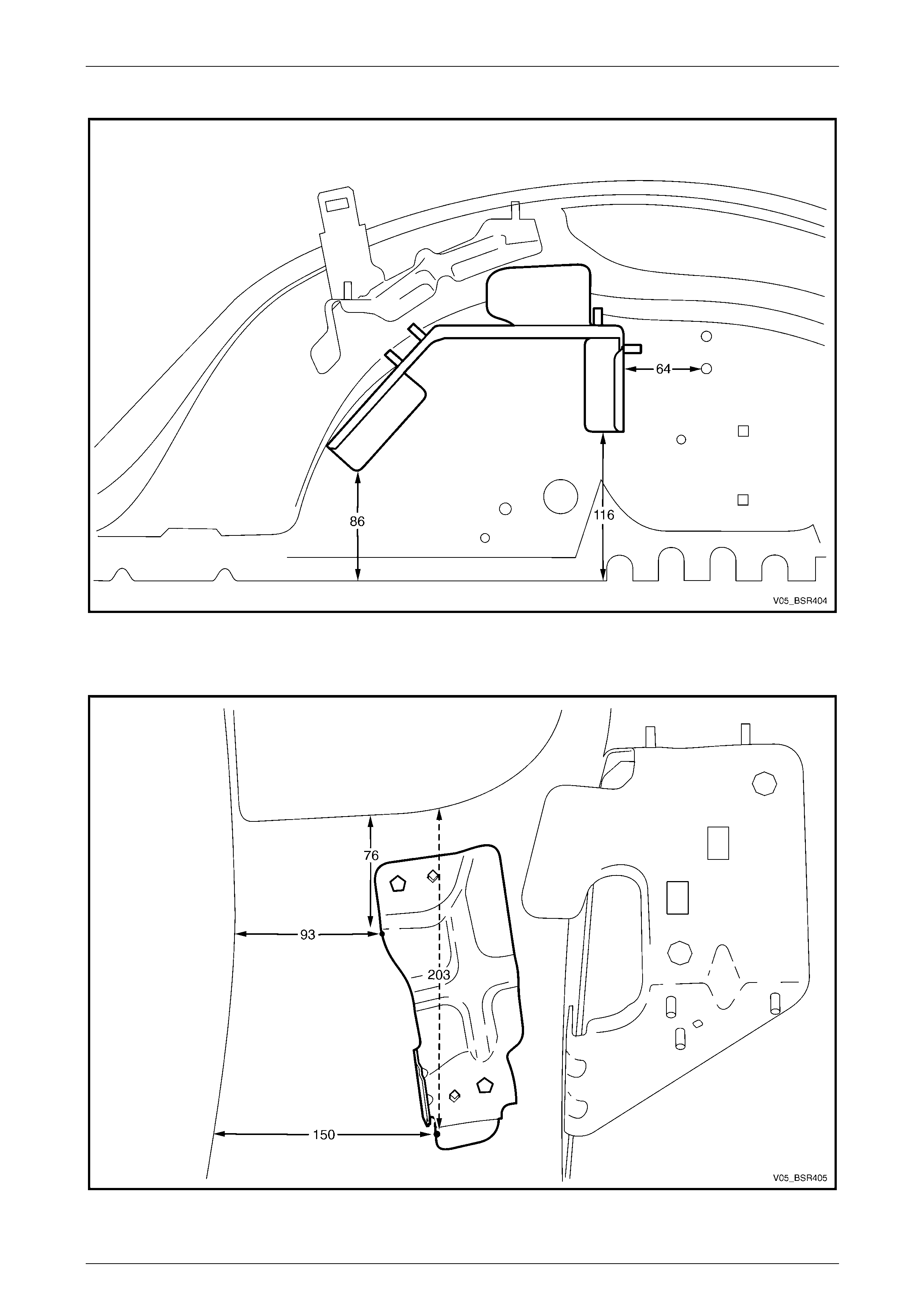
1 Place the bracket in the correct position on the wheelhouse panel, refer to Figure 4 – 6 3 or Figure 4 – 64.
2 Spot or plug weld, nine places for the brake pressure modulator bracket assembly and seven plac es for the
multiuse relay housing bracket in the positions shown, refer to Figure 4 – 62.
4 Front End Page 4-30
Page 4-30
Brake Pressure Modulator Bracket Assembly
Figure 4 – 63
Multiuse Relay Housing Bracket
Figure 4 – 64