7 Body Side Page 7–1
Page 7–1
Section 7
Body Side
ATTENTION
Before performing any service operation or other procedure described in this Section, refer to Section 2
Precautions in this Supplement and Section 00 Warnings, Cautions and Notes in the MY2005 WL Service
Information for correct workshop practices with regard to safety and/or property damage.
The structure of the body shell has been
developed using complex design and
development techniques. In addition to
meeting all required standards, the vehicle
body is also a critical part of the overall safety
systems. It is therefore imperative the repair
procedures described here are adhered to
during all vehicle body repairs.
1 General Information ...............................................................................................................................2
1.1 Body Side Components ........................................................................................................................................ 2
2 Service Operations.................................................................................................................................4
2.1 Rear Quarter Panel – Replace............................................................................................................................... 4
Remove................................................................................................................................................................... 4
Replace................................................................................................................................................................... 7
2.2 Tail Lamp Housing, Quarter Panel Low er Extension and Quarter Panel Upper Extension – Replace......... 11
Remove................................................................................................................................................................. 11
Replace................................................................................................................................................................. 12
2.3 Door Opening Frame Assembly – Replace........................................................................................................ 14
Remove................................................................................................................................................................. 14
Replace................................................................................................................................................................. 19
2.4 Door Opening Frame Assembly – Partial Replace, Hinge Pillar...................................................................... 24
Remove................................................................................................................................................................. 24
Replace................................................................................................................................................................. 27
2.5 Door Opening Frame Assembly – Partial Replace, Centre Pillar..................................................................... 32
Remove................................................................................................................................................................. 32
Replace................................................................................................................................................................. 35
2.6 Door Opening Frame Assembly – Partial Replace, Body Lock Pillar.............................................................. 39
Remove................................................................................................................................................................. 39
Replace................................................................................................................................................................. 40
2.7 Door Opening Frame Assembly – Partial Replace, Rocker Panel................................................................... 43
Remove................................................................................................................................................................. 43
Replace................................................................................................................................................................. 46
2.8 Fender Lower Rear Bracket – Replace............................................................................................................... 50
2.9 Hinge Pillar Inner Panel Assembly – Replace ................................................................................................... 51
Remove................................................................................................................................................................. 51
Replace................................................................................................................................................................. 52
2.10 Quarter Panel Inner Assembly – Replace.......................................................................................................... 56
Remove................................................................................................................................................................. 56
Replace................................................................................................................................................................. 58
2.11 Quarter Panel Inner Assembly – Partial Replace.............................................................................................. 61
Remove................................................................................................................................................................. 61
Replace................................................................................................................................................................. 63
7 Body Side Page 7–2
Page 7–2
1 General Information
This Section describes the replacement procedures for the body side com ponents of the body structure. Removal of bo lt-
on panels and mechanical co mponents is not covered.
When repairing the body side of the vehicle, care must be taken to ensure the structure is returned to its origi nal
production configuration. This is especially important to maintain side impact standards and for the vehicle’s occ upant
protection system to operate correctly.
This Section includes door opening frame assembly partial replacement procedures for the hinge pillar, centre pillar, lock
pillar and rocker panel. These procedures must be followed carefully, as they regularly involve hidden reinforcement
panels. The cutting locations specified are the only places allowable.
NOTE
• A sunroof option is available that is fitted on
the production line. To cater for this option, a
stainless steel front drain tube is also fitted
within the hinge pillar cavity, therefore the
partial replacement procedure for the hinge
pillar must not be performed on these
vehicles.
• It is imperative the correct body adhesives,
sealers, deadeners and cavity waxes are
used when repairing th e body structure. Refer
to Section 3 Body Construction.
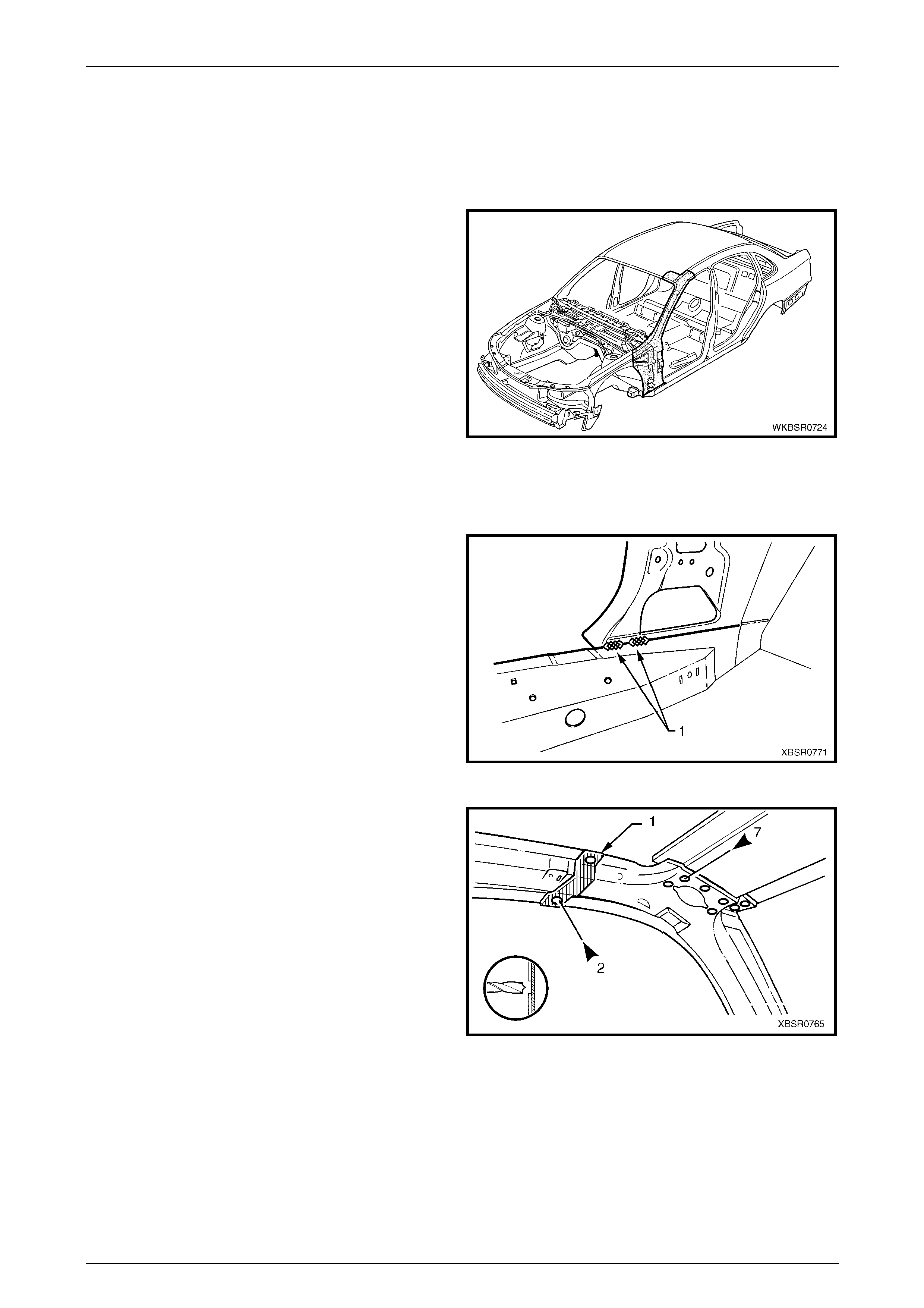
1.1 Body Side Components
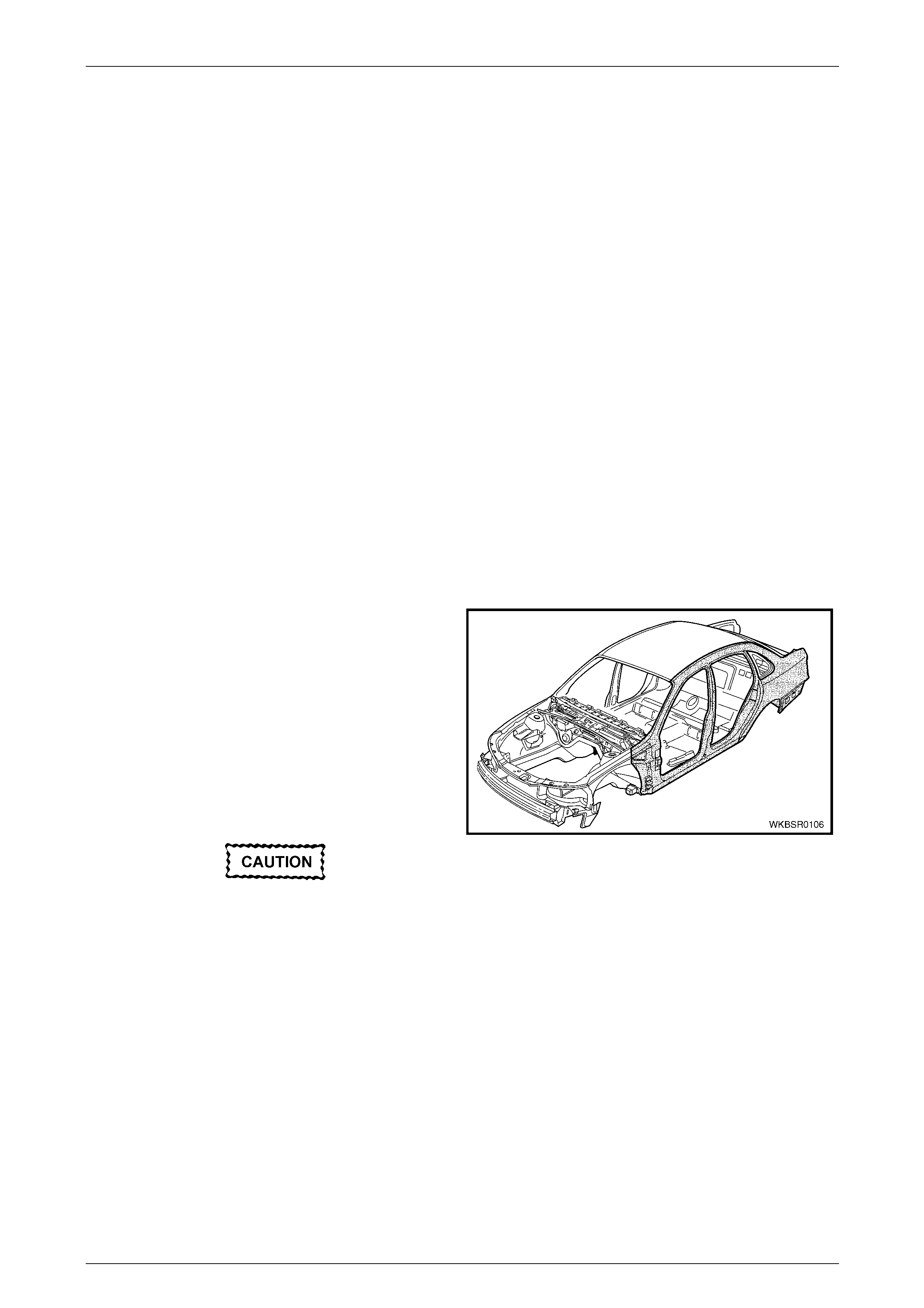
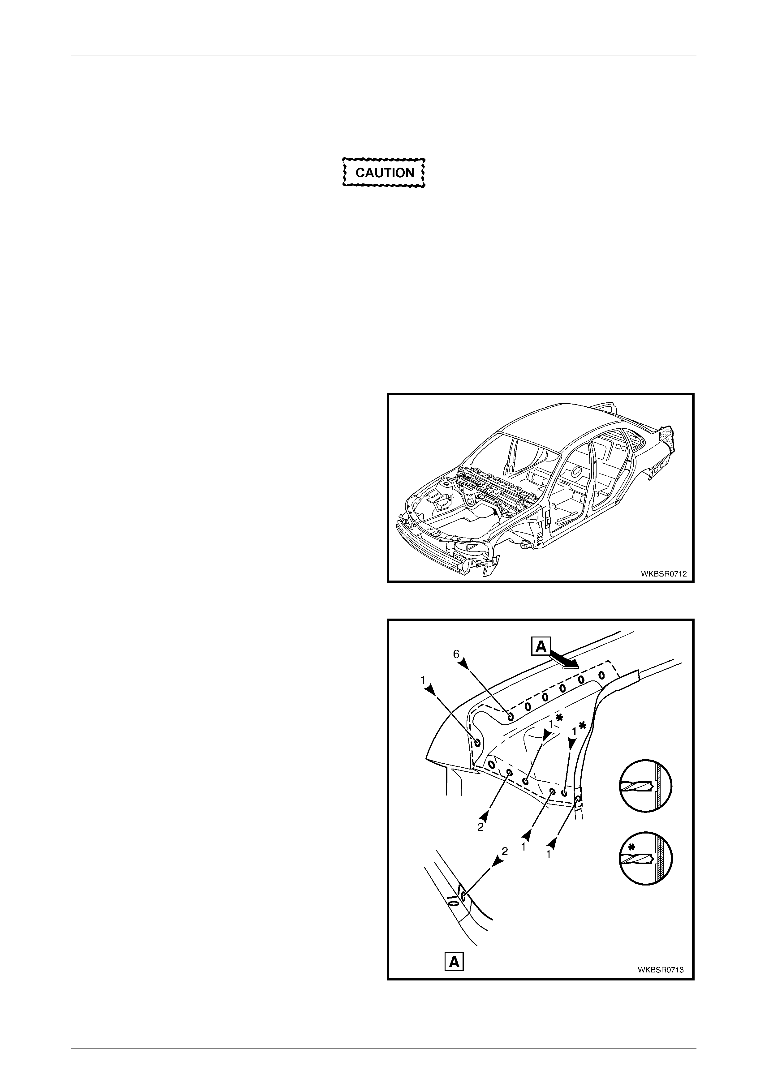
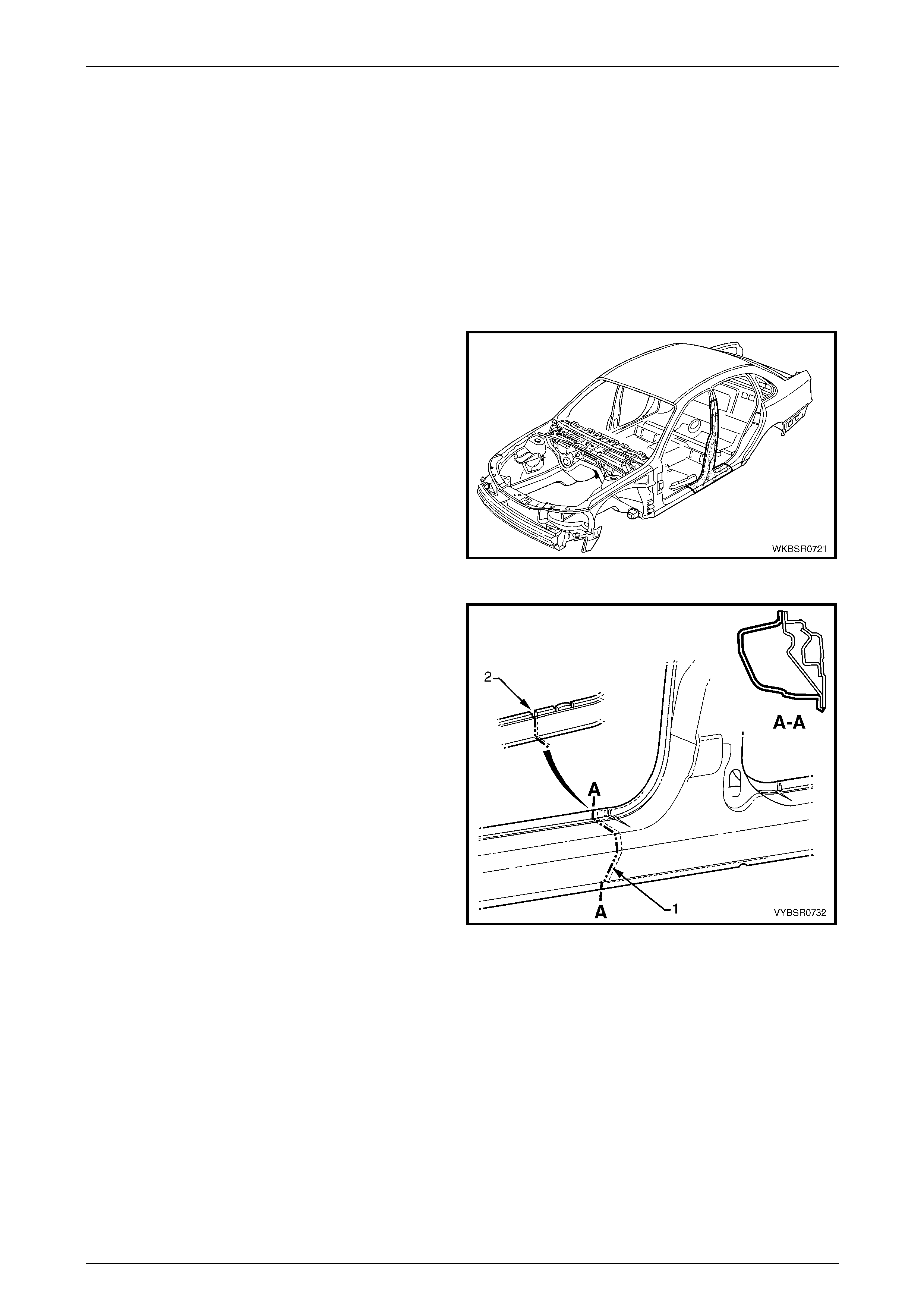
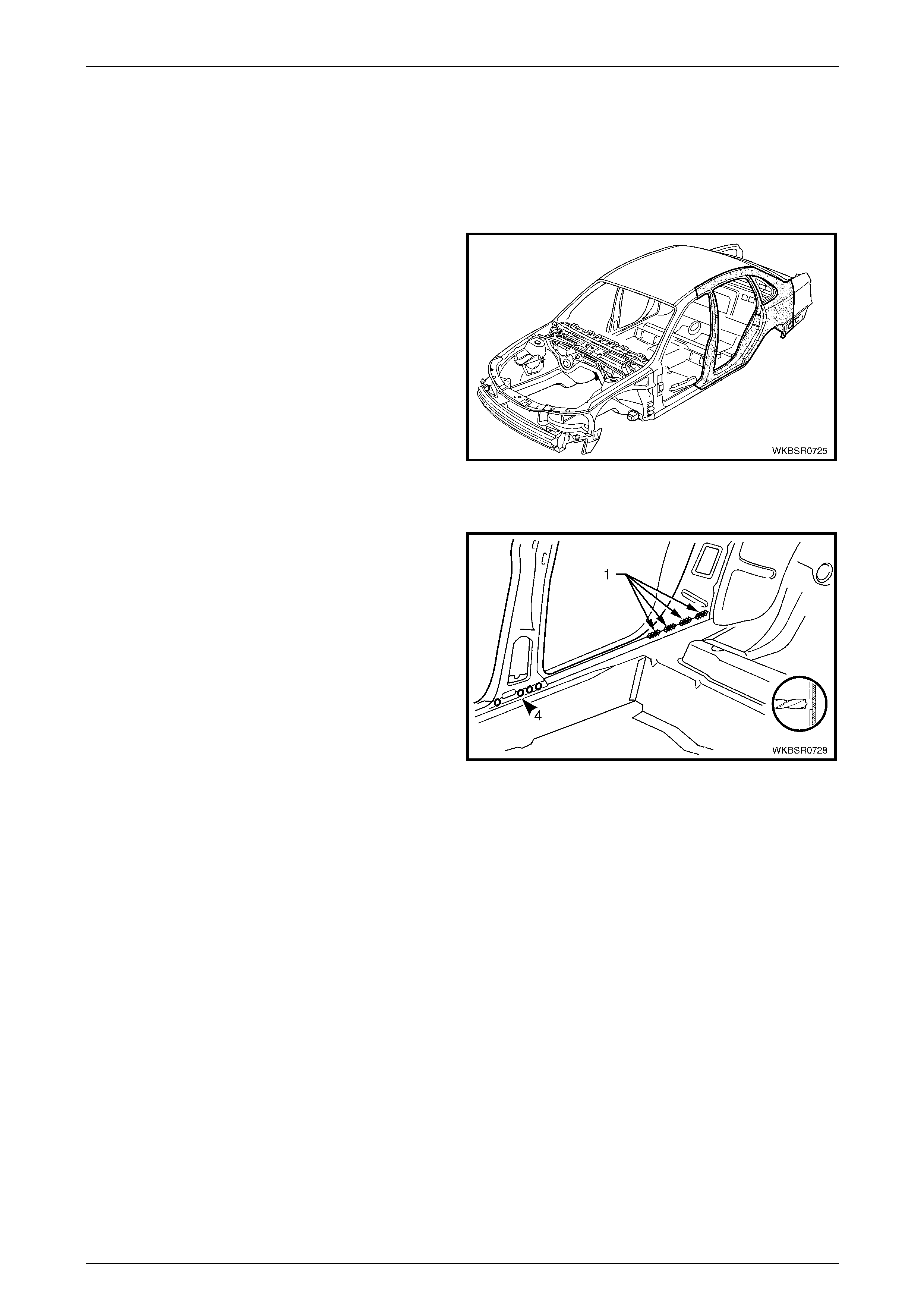
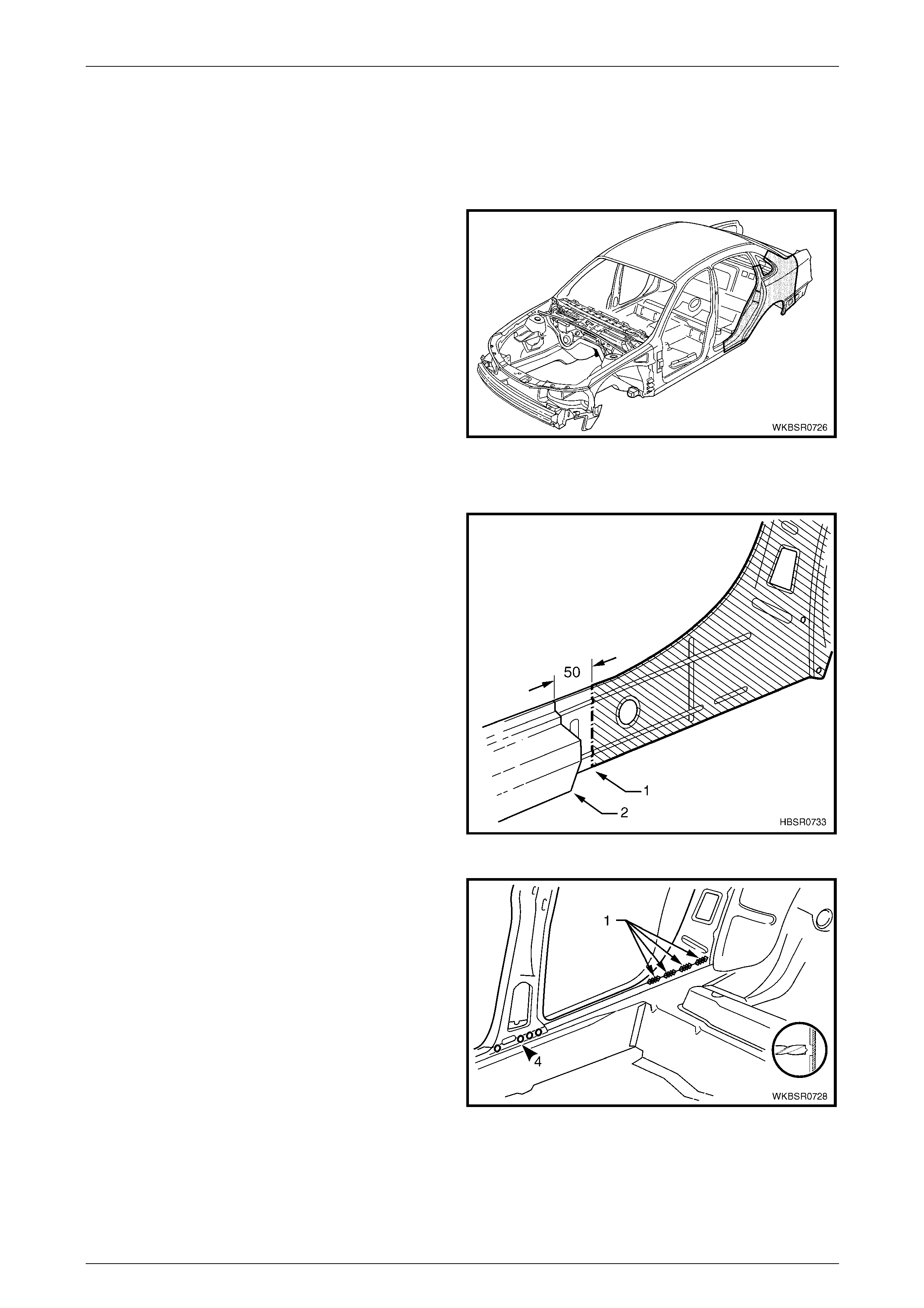
The shaded components in Figure 7 – 1 are those dealt with
in this Section.
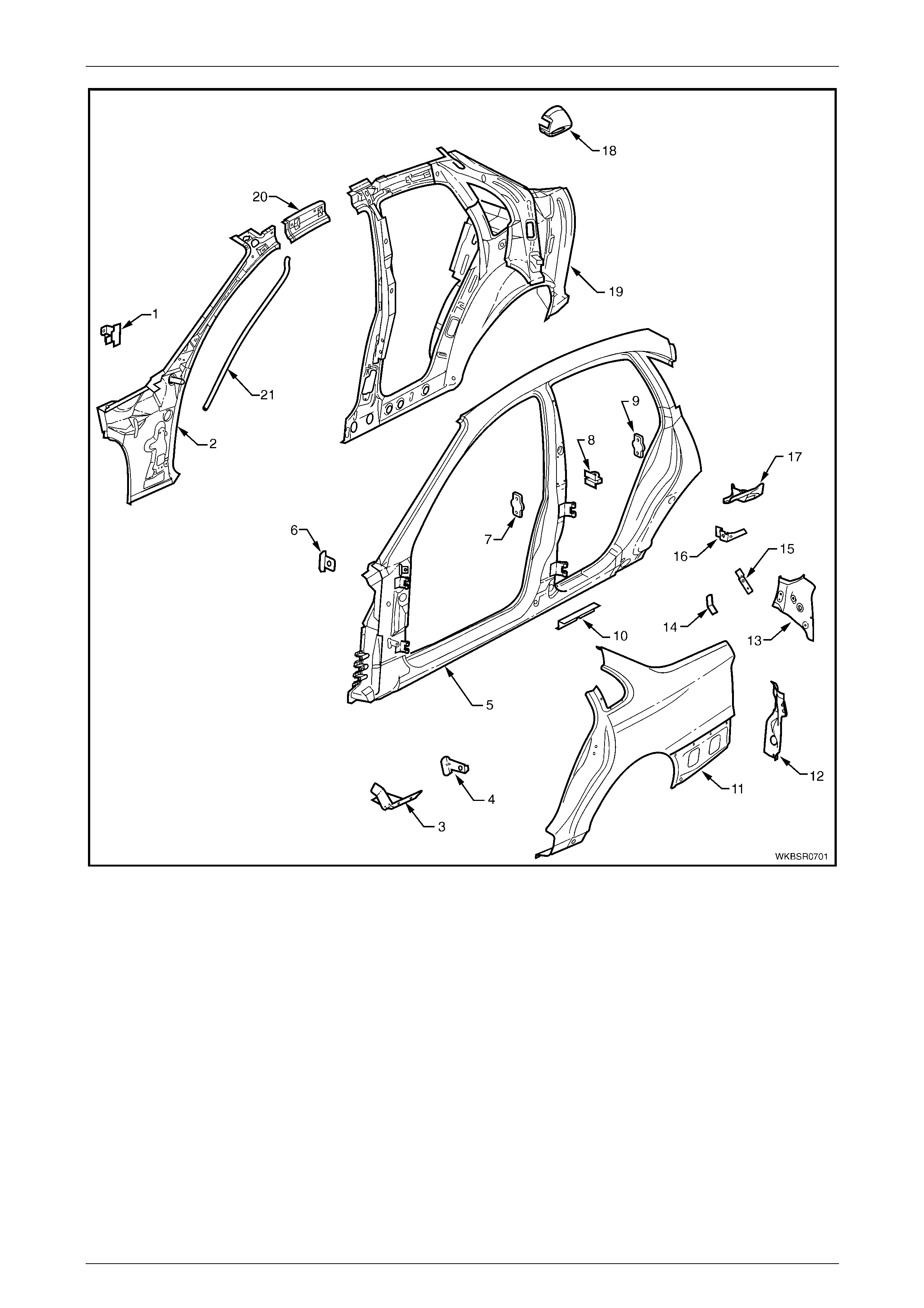
The components and assemblies shown in Figure 7 – 2 are
the serviceable parts that form the basis of the repair
procedures in this Section. For a detailed view of the body
components, refer to Section 3 Body Construction.
NOTE
Always refer to an Authorised Retailer for spare
parts availability configurations.
Cavity foam may be used within the hinge,
centre and lock pillars. Care needs to be
taken when repairing the vehicle in these
areas, refer to Section 2 Precautions prior to
beginning any work for further information
regarding the use of cavity foam.
Figure 7 – 1
7 Body Side Page 7–3
Page 7–3
Figure 7 – 2
Legend
1 Hinge Pillar Trim Panel Bracket, Left-hand / Right-hand
2 Hinge Pillar Inner Panel Assembly, Left-hand / Right-hand
3 Fender Lower Rear Bracket, Left-hand / Right-hand
4 Fender Rear Bracket, Left-hand / Right-hand
5 Door Opening Frame Assembly, Left-hand / Right-hand
6 Fender Upper Rear Bracket, Left-hand / Right-hand
7 Front Door Striker Anchor Plate, Left-hand / Right-hand
8 Rear Door Check Link Bracket, Left-hand / Right-hand
9 Rear Door Striker Anchor Plate, Left-hand / Right-hand
10 Underbody Jacking Locator, Left-hand / Right-hand
11 Rear Quarter Panel, Left-hand / Right-hand
12 Quarter Panel Lower Extension, Left-hand / Right-hand
13 Tail Lamp Housing, Left-hand / Right-hand
14 Wiring Harness Bracket, Left-hand / Right-hand
15 Tail Lamp Connector Bracket, Left-hand / Right-hand
16 Rear Compartment Trim Attach Bracket, Left-hand / Right-
hand
17 Quarter Panel Upper Extension, Left-hand / Right-hand
18 Fuel Filler Pipe Housing
19 Quarter Panel Inner Assembly, Left-hand / Right-hand
20 Quarter Panel Inner Extension, Left-hand / Right-hand
21 Sunroof Front Drain Tube, Left-hand / Right-hand
NOTE
• Door opening frame assembly (5) includes
parts 3, 4, 6, 7, 8, 9 and 10.
• Quarter panel inner assembly (19) includes
parts 20 and the rear wheelhouse inn er panel
assembly which is also available separately,
refer to Section 10 Body Rear.
7 Body Side Page 7–4
Page 7–4
2 Service Operations
2.1 Rear Quarter Panel – Replace
To avoid the possibility of fire, take particular
care when cuttin g or w elding at the rear of the
vehicle. Remove the fuel tank and plug the
fuel lines.
NOTE
This procedure details the removal of the rear
quarter panel as an assembly with the tail lamp
housing, quarter panel upper extension, quarter
panel lower extension and fuel filler pipe housing
(for right-hand side). Ho wever these parts are not
available as an assembly and must be ordered
separately.
Remove
1 Remove the adjacent bolt-on panels and components
as described in the appropriate Section of the MY2005
WL Service Information.
2 Remove the rear window, refer to
Section 1A6 Stationary Windows in the MY2005 WL
Service Information.
3 Remove the rear bumper impact bar, refer to
Section 3 Body Construction.
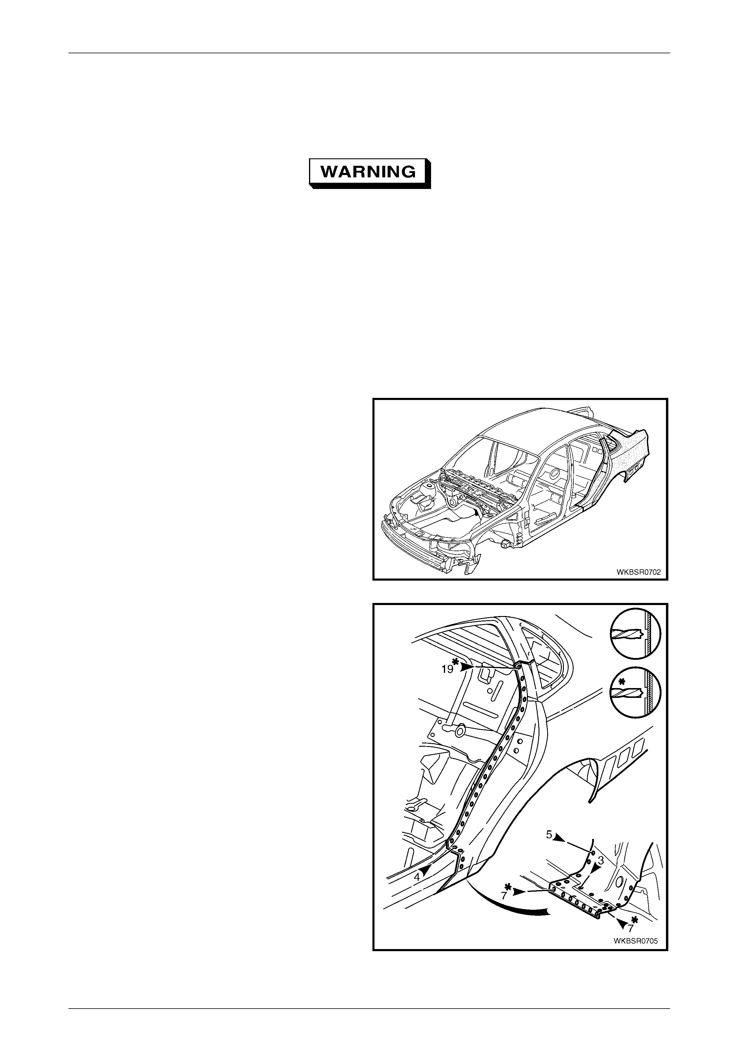
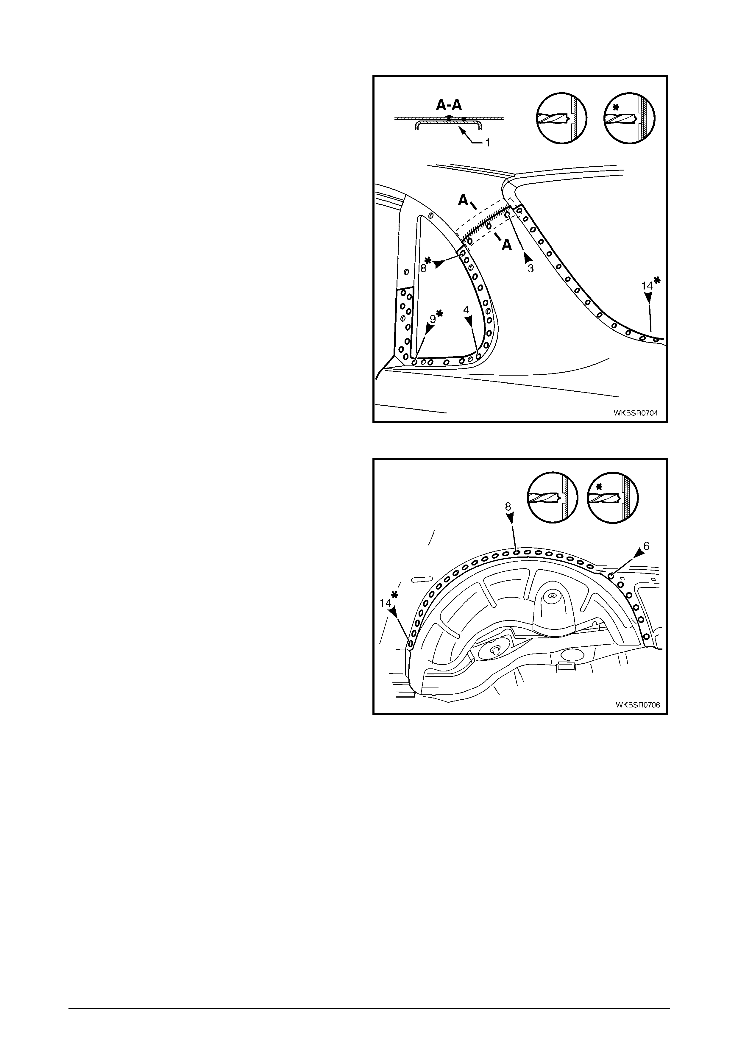
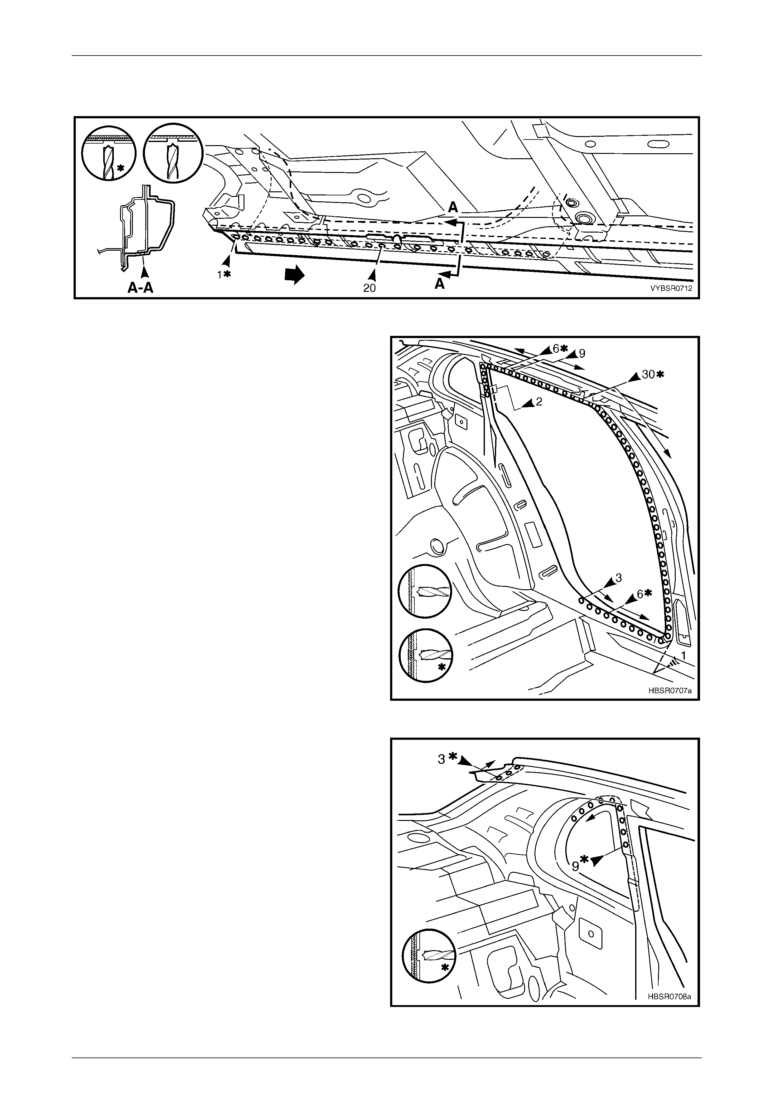
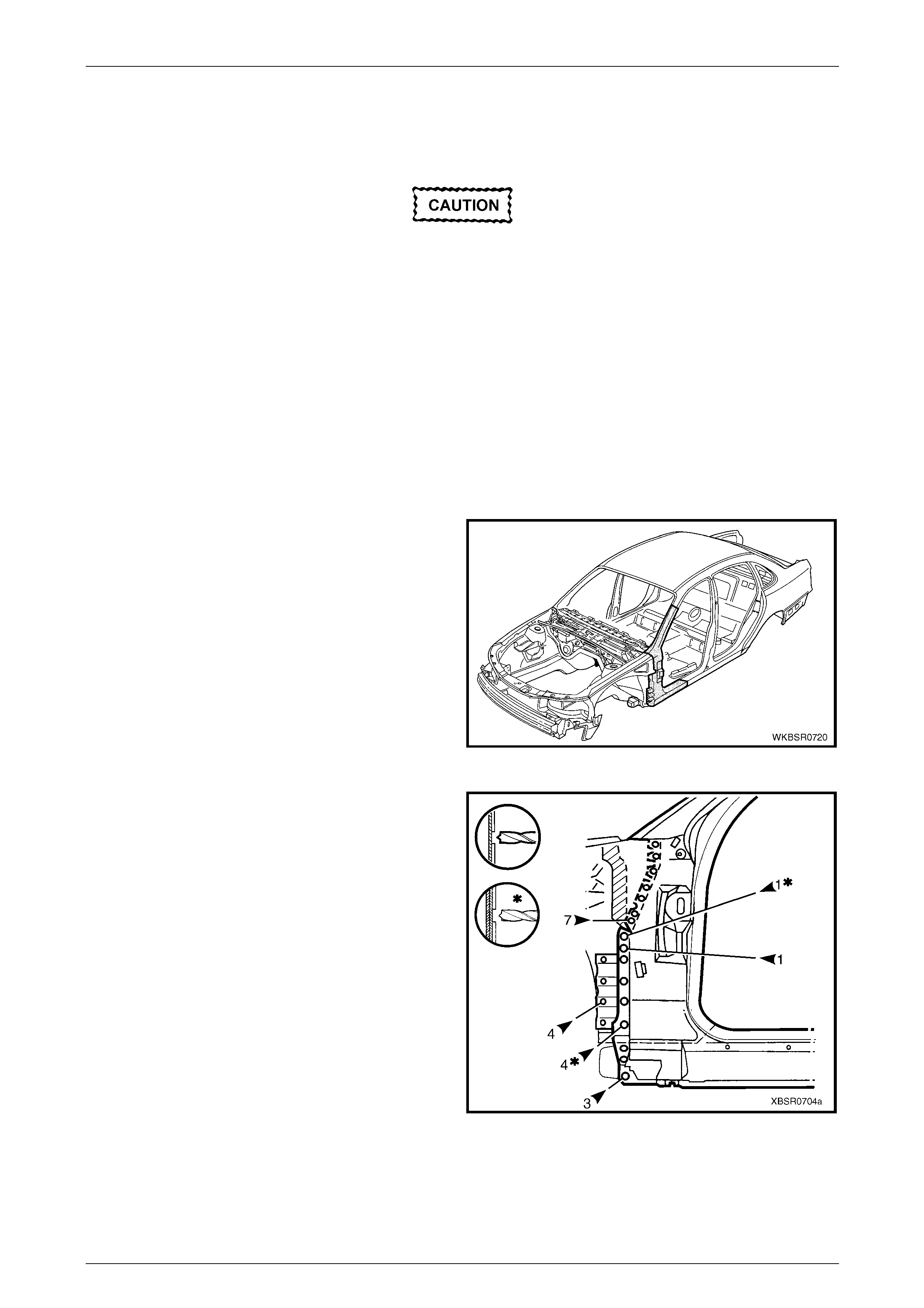
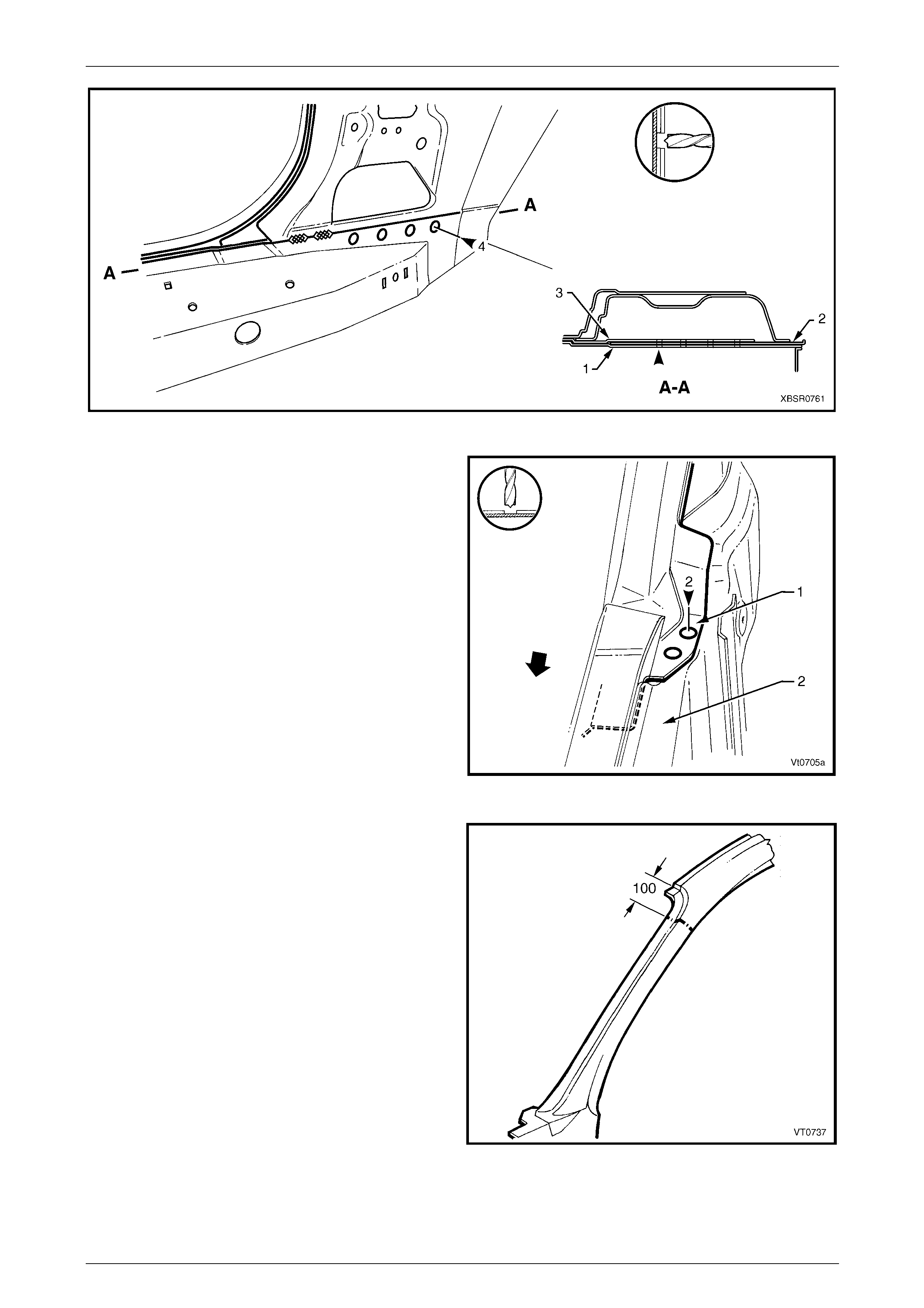
Figure 7 – 3
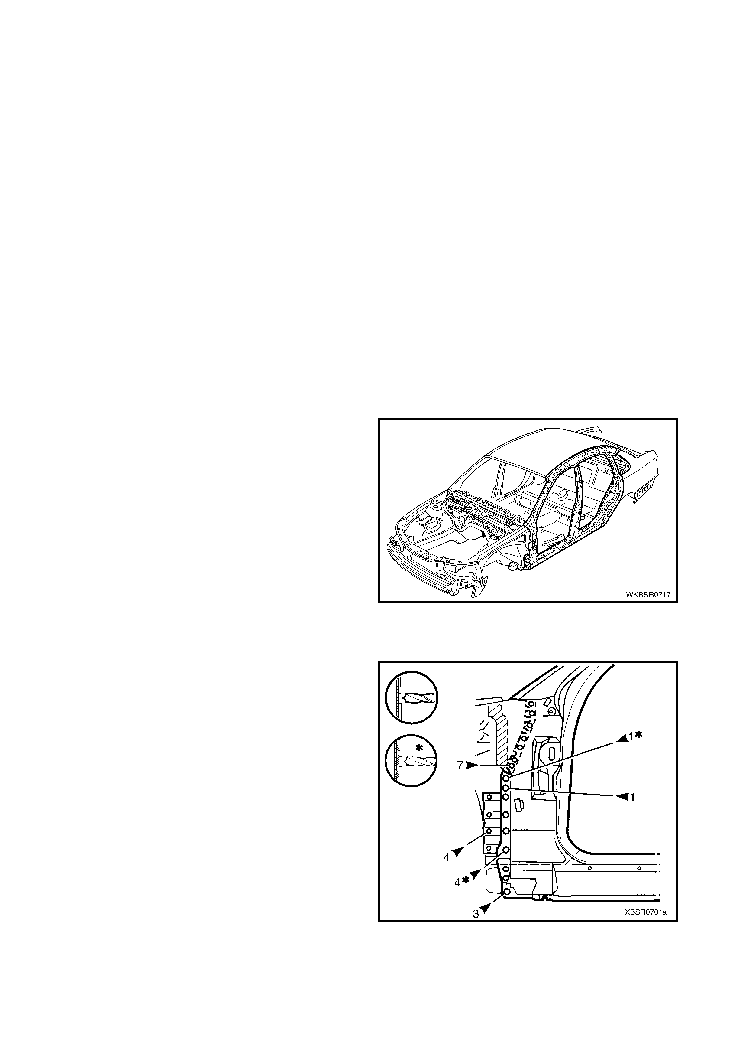
4 Spot cut the welds attaching the rear quarter panel to
the door opening frame assembly.
NOTE
Unless other panels are to be removed, drill
through the single outer panel only.
Figure 7 – 4
7 Body Side Page 7–5
Page 7–5
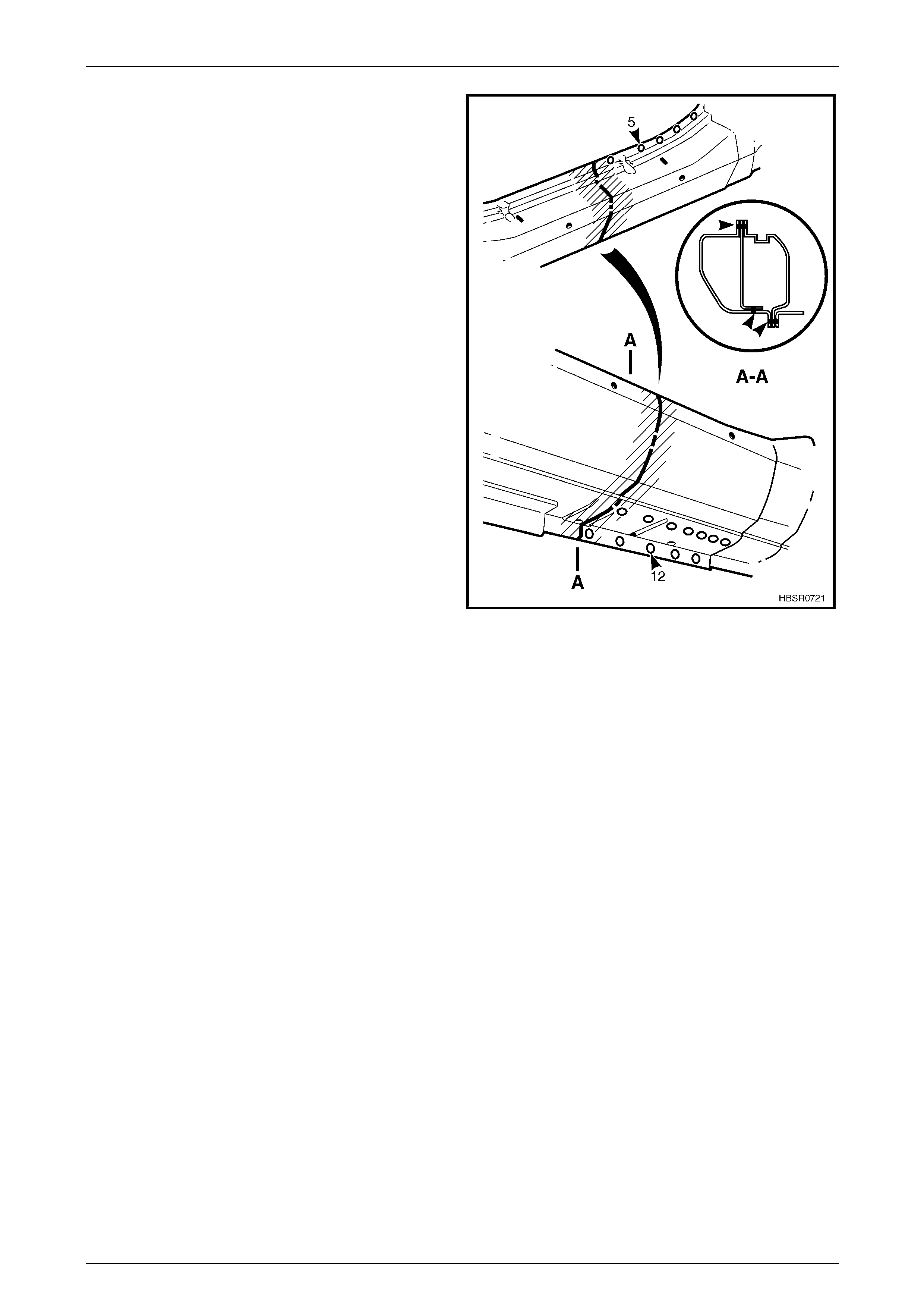
5 Using an oxy/acetylene torch and wire brush, carefully
heat and remove the bronze weld from the braze joint.
NOTE
Place several wet rags around the area to
minimise heat transfer.
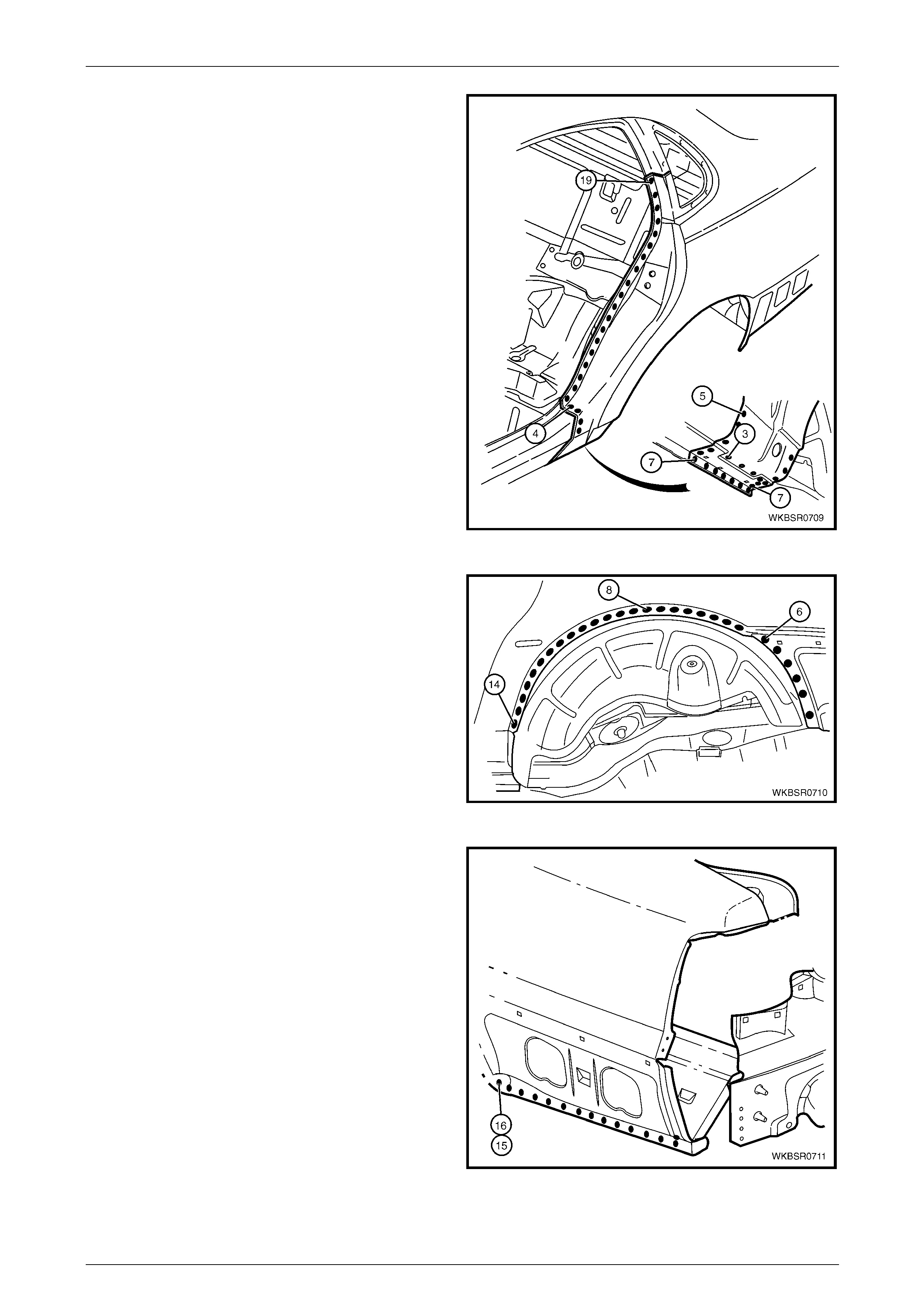
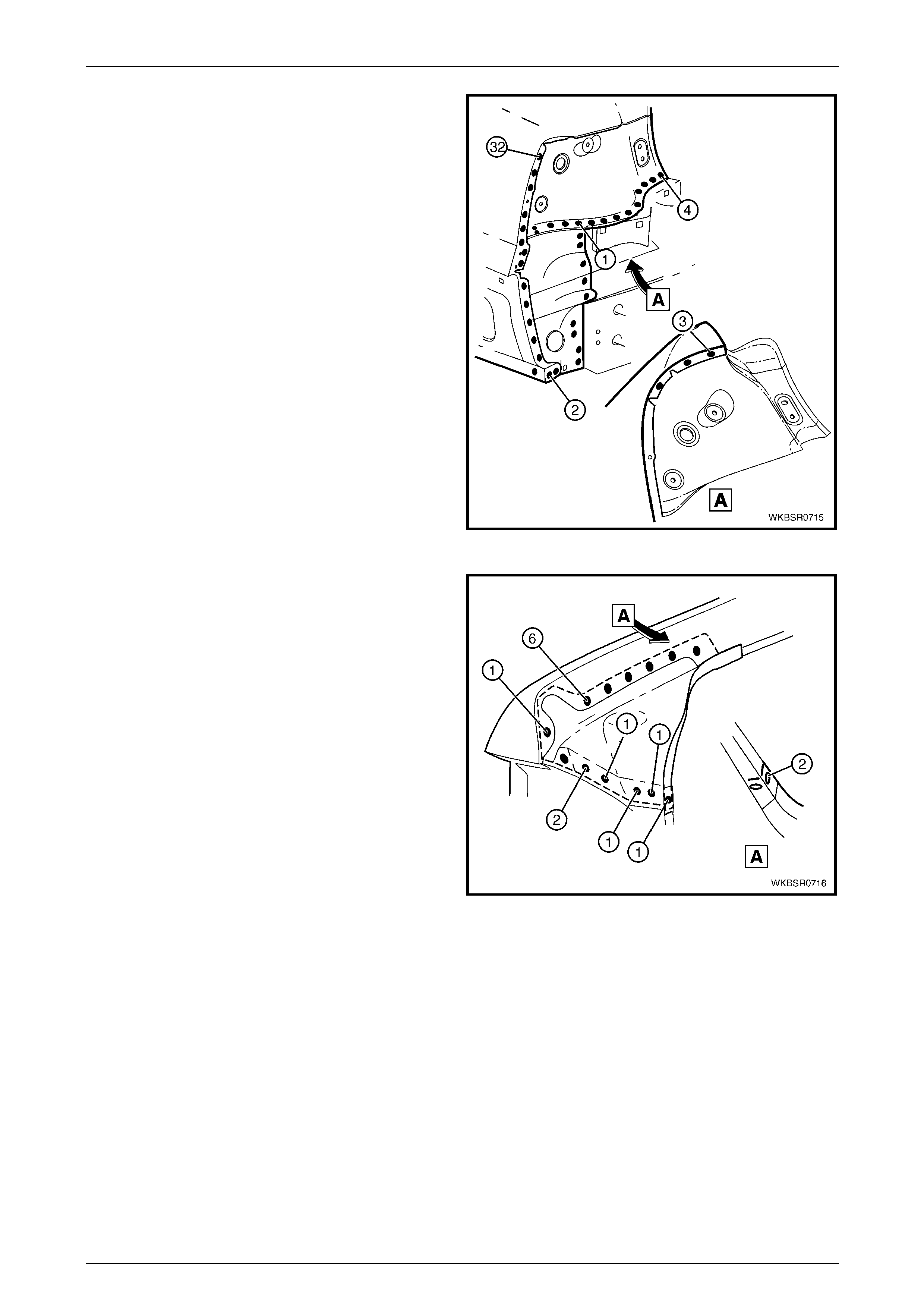
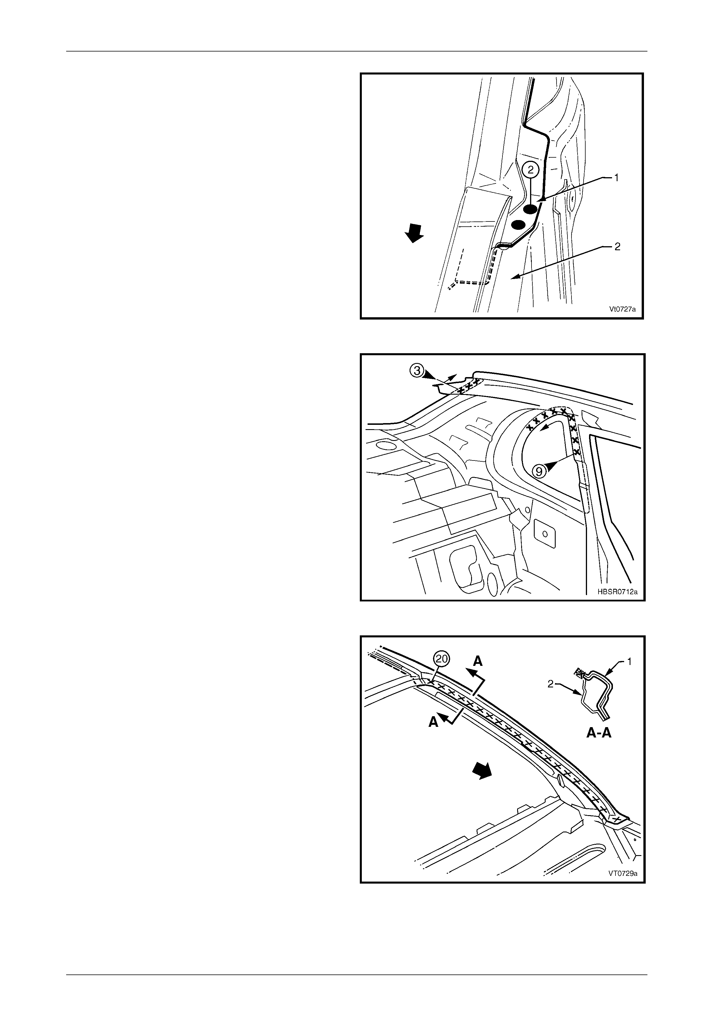
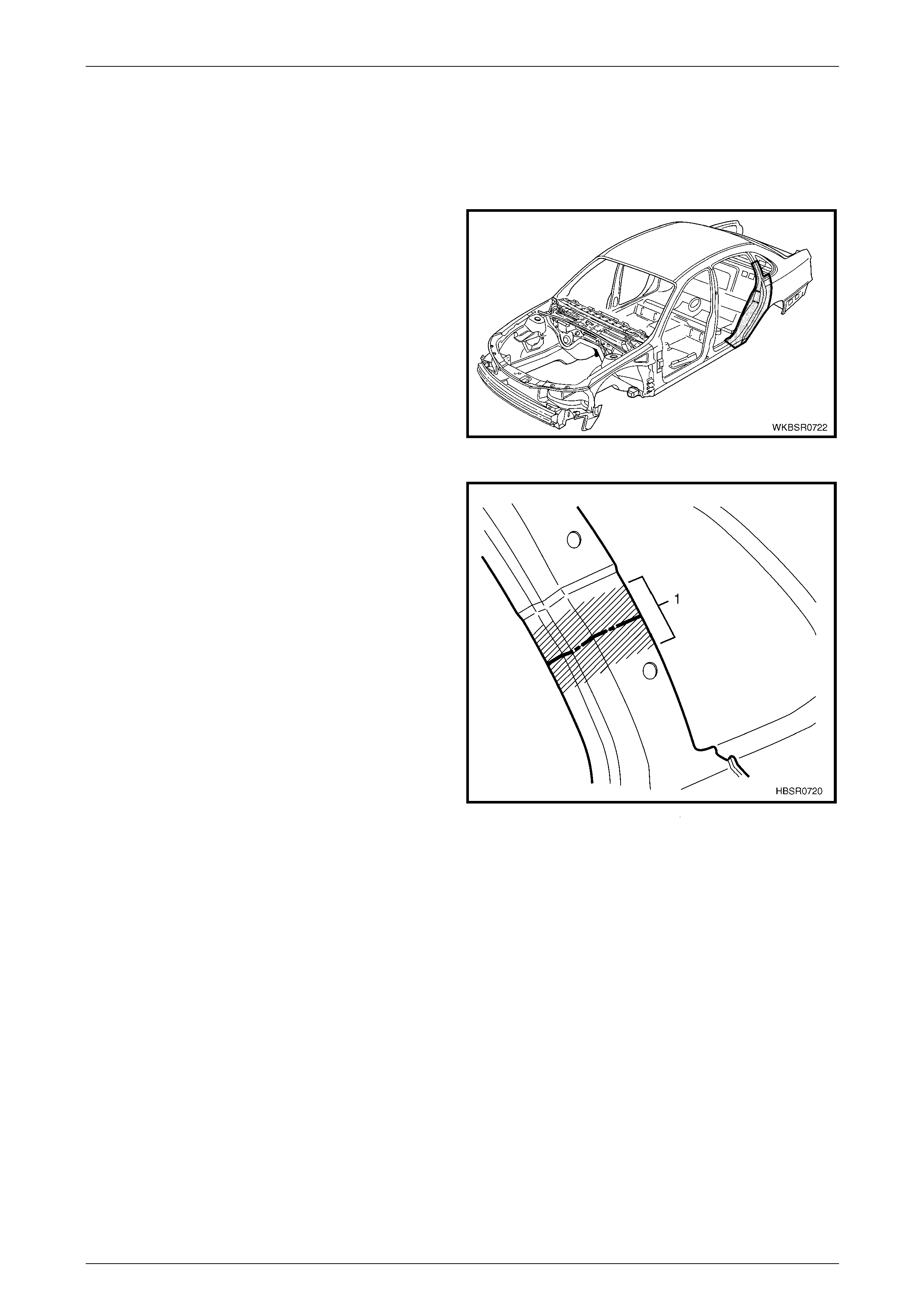
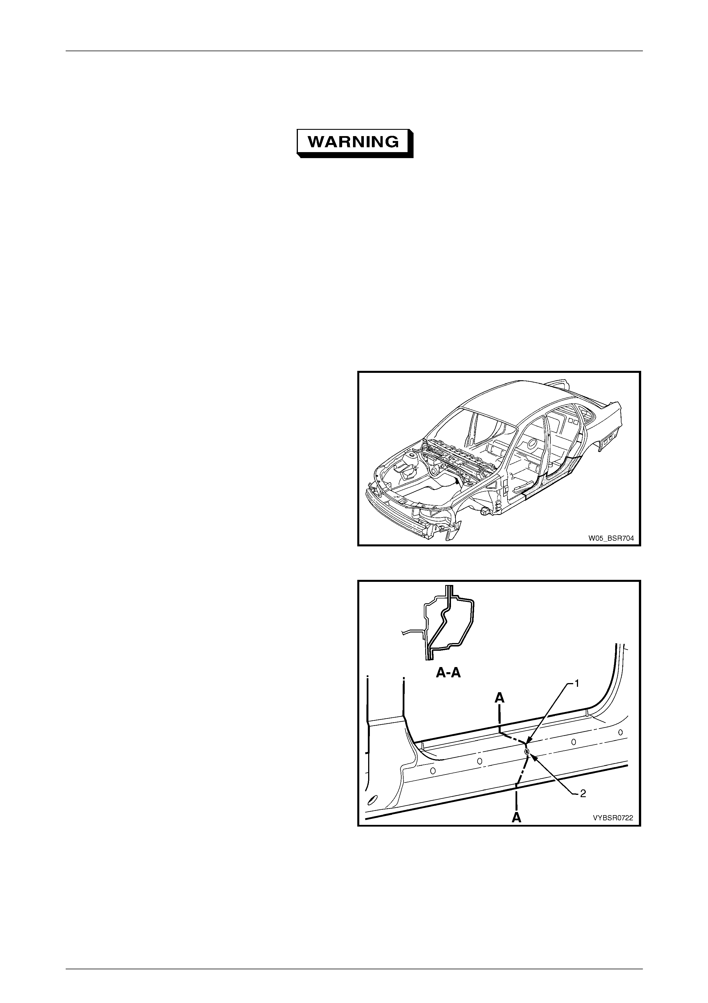
6 Spot cut the welds to detach the rear quarter panel
from the quarter panel inner assembly and braze joint
reinforcement (1).
Figure 7 – 5
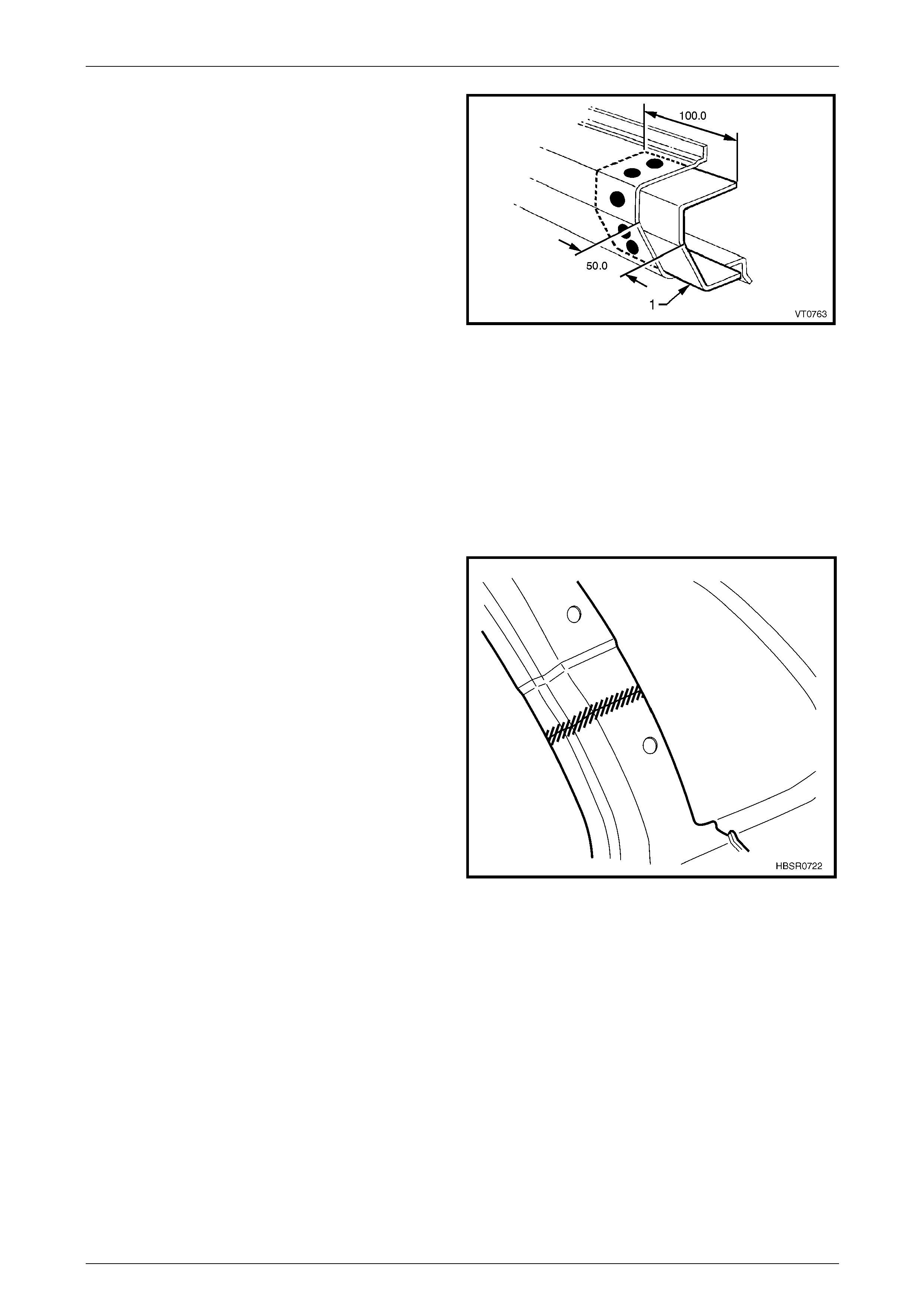
7 Spot cut the welds to detach the rear quarter panel
from the quarter panel inner assembly around the
wheel arch.
Figure 7 – 6
7 Body Side Page 7–6
Page 7–6
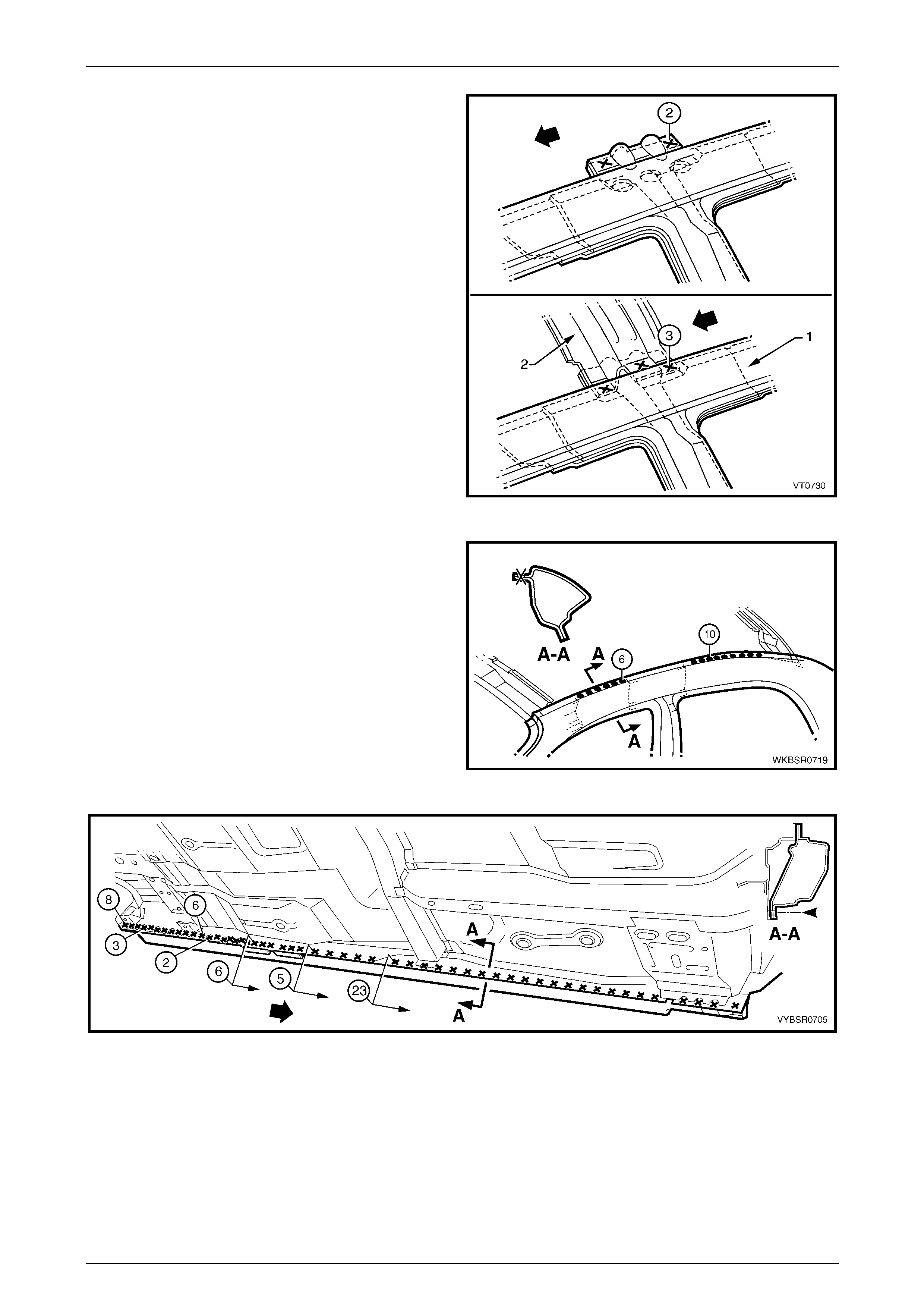
8 Spot cut the rear quarter panel from the rear end lo wer
panel and rear compartment floor panel outer
extension.
9 Spot cut the tail lamp housing and quarter panel lower
extension panel from the rear end lower panel.
10 Spot cut along the lower edge of the quarter panel and
where the quarter pane l lower extension and tail lamp
panel joins the rear end pa nel.
NOTE
If the tail lamp housing, quarter panel lower
extension and quarter pa nel upper extension are
to remain, modify this procedure accordingly.
Also refer to 2.2 Tail Lamp Housing, Quarter
Panel Lower Extension a nd Q uarter Panel U pper
Extension – Replace.
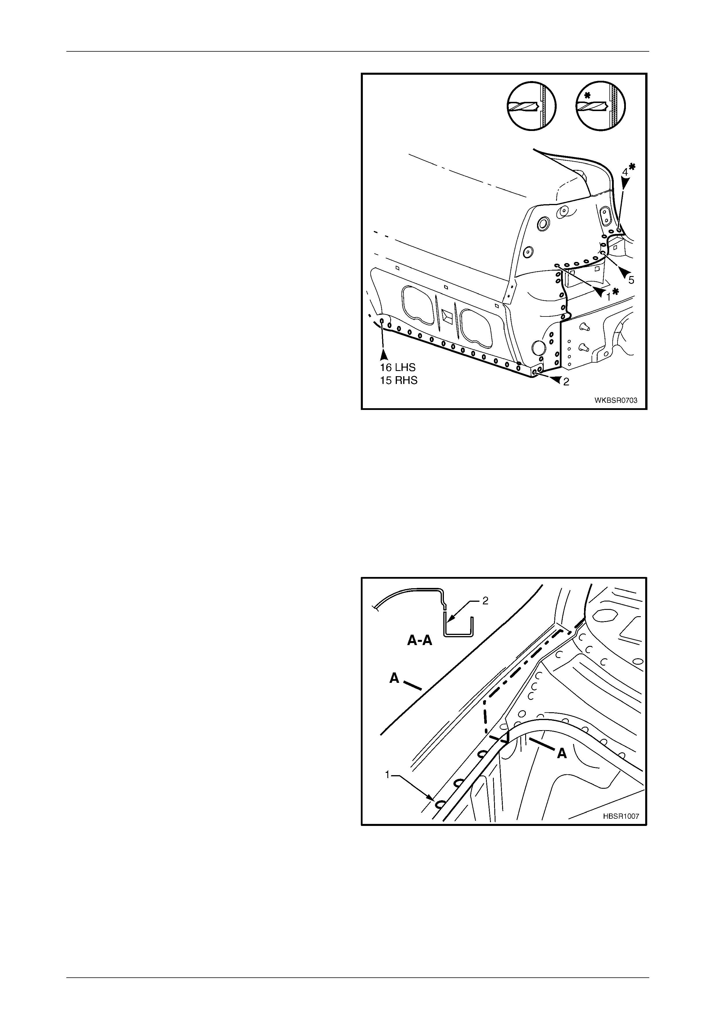
Figure 7 – 7
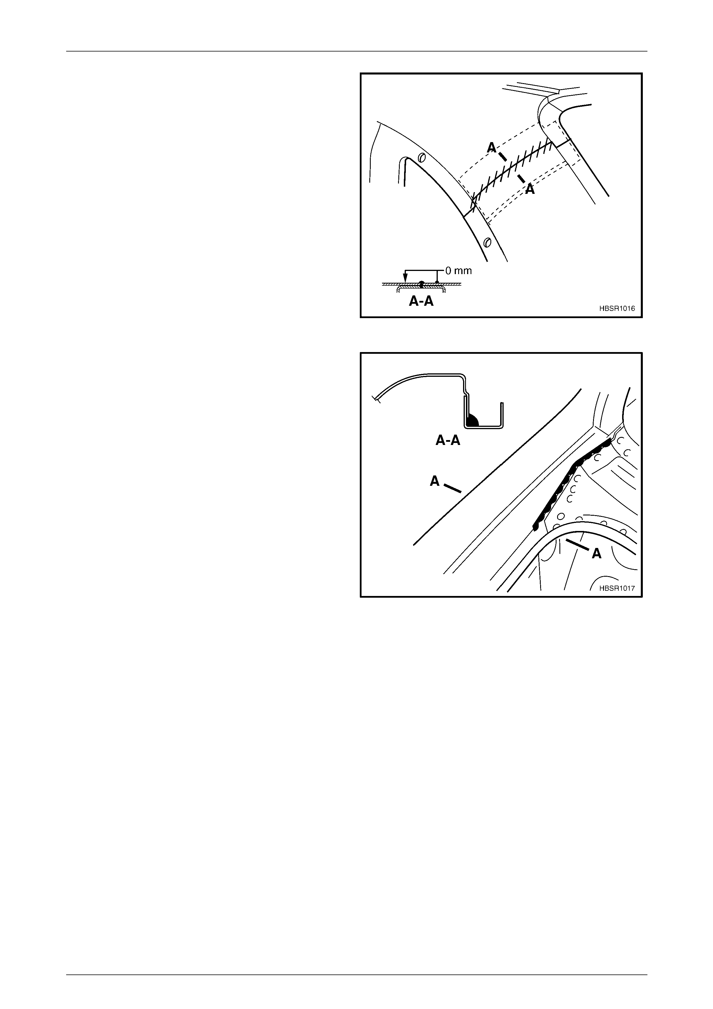
NOTE
The quarter panel is sandwiched between the
water channel and back panel upper-rear at the
base of the rear windscreen. Cutting the panel at
this point, as described below, rather than
removing extra panels, will save considerable
time and effort as structural adhesive is used in
this area.
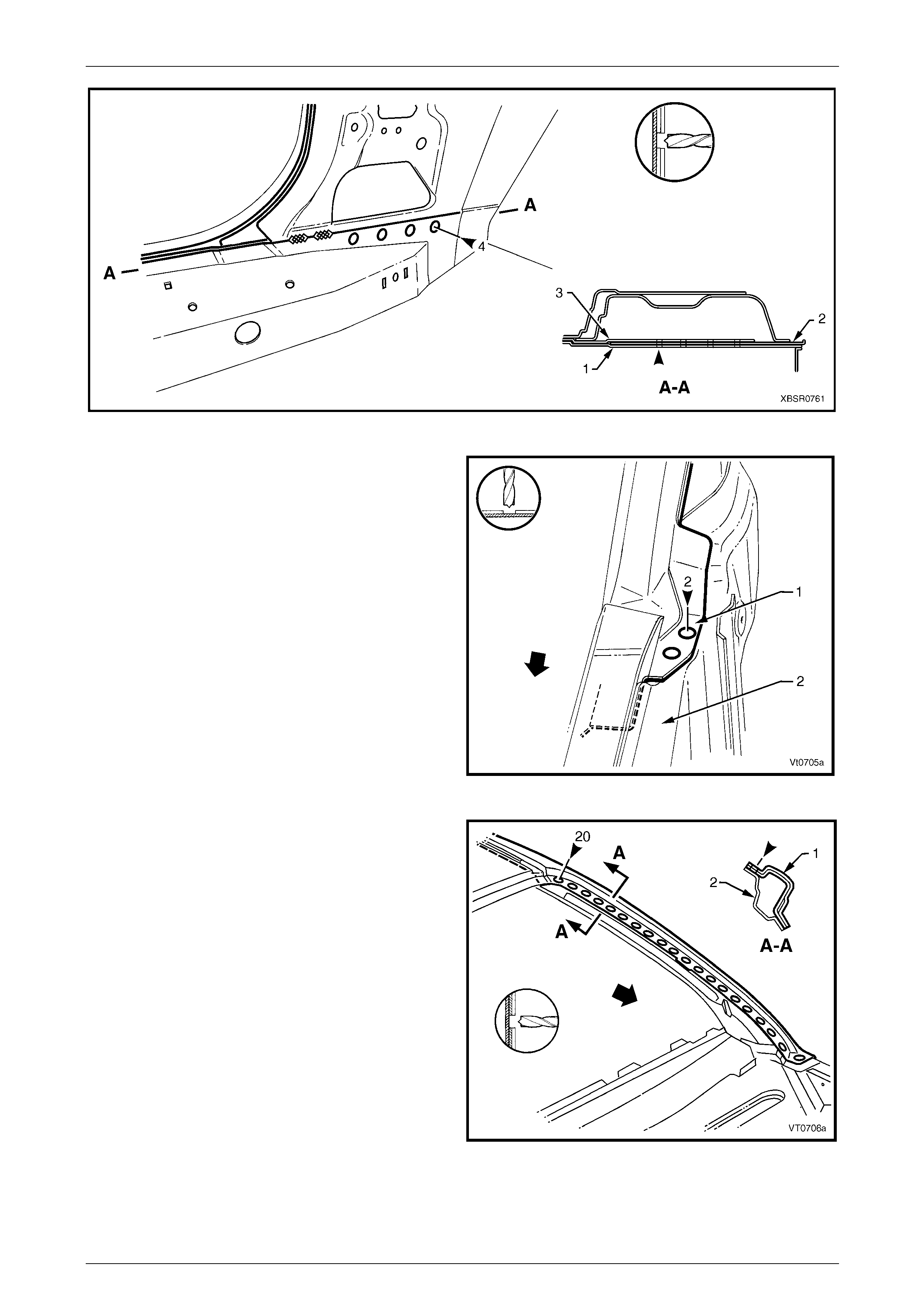
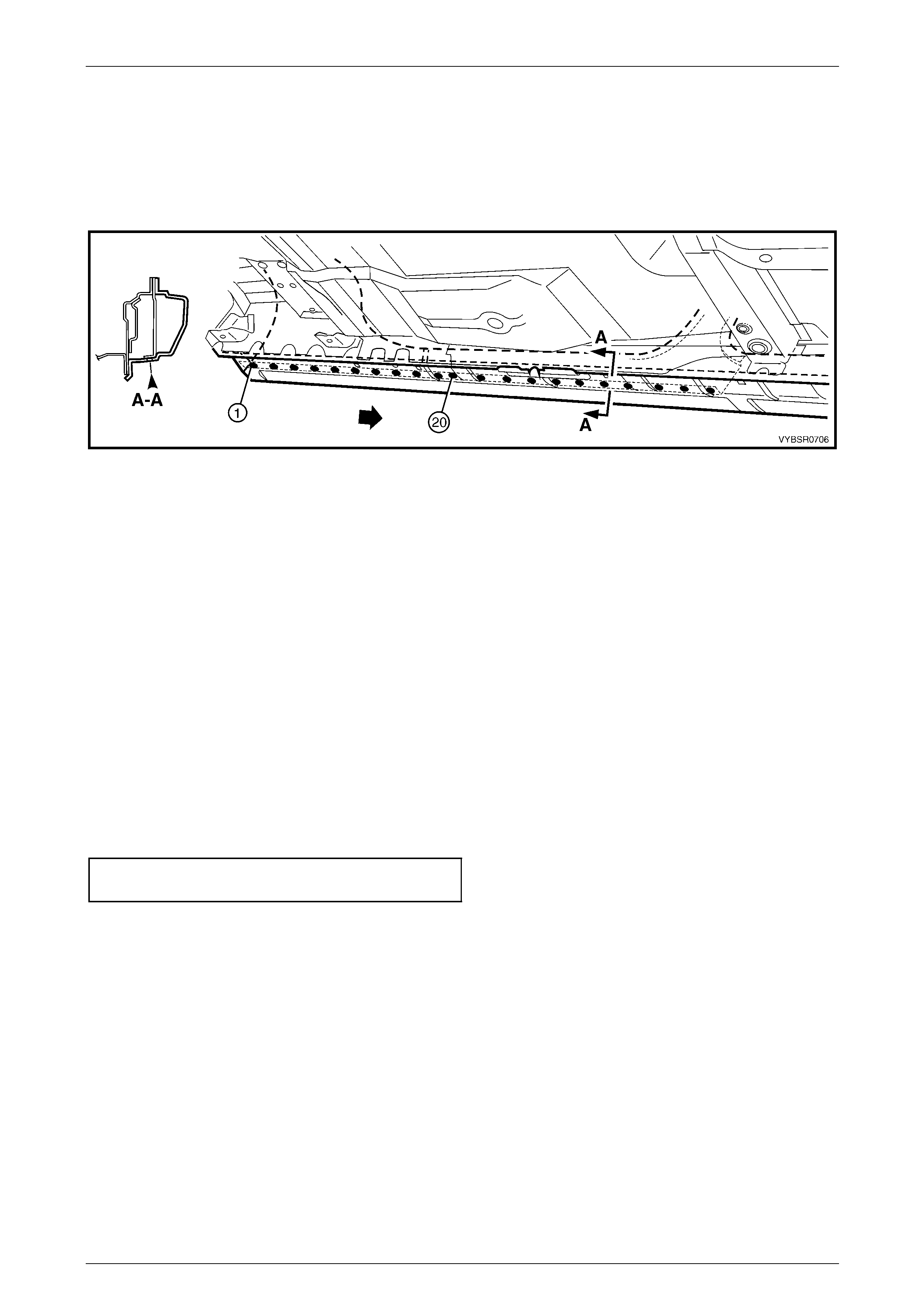
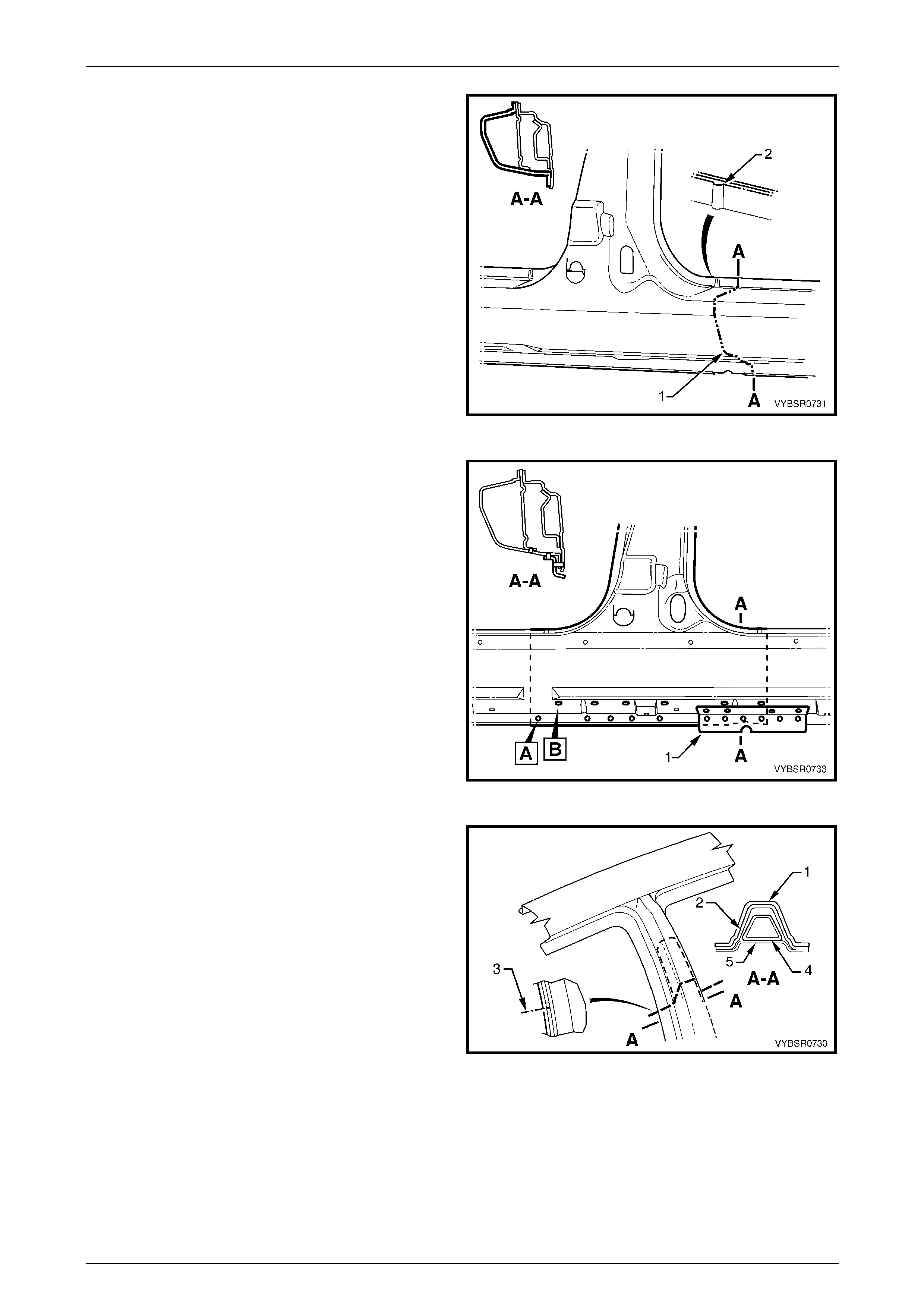
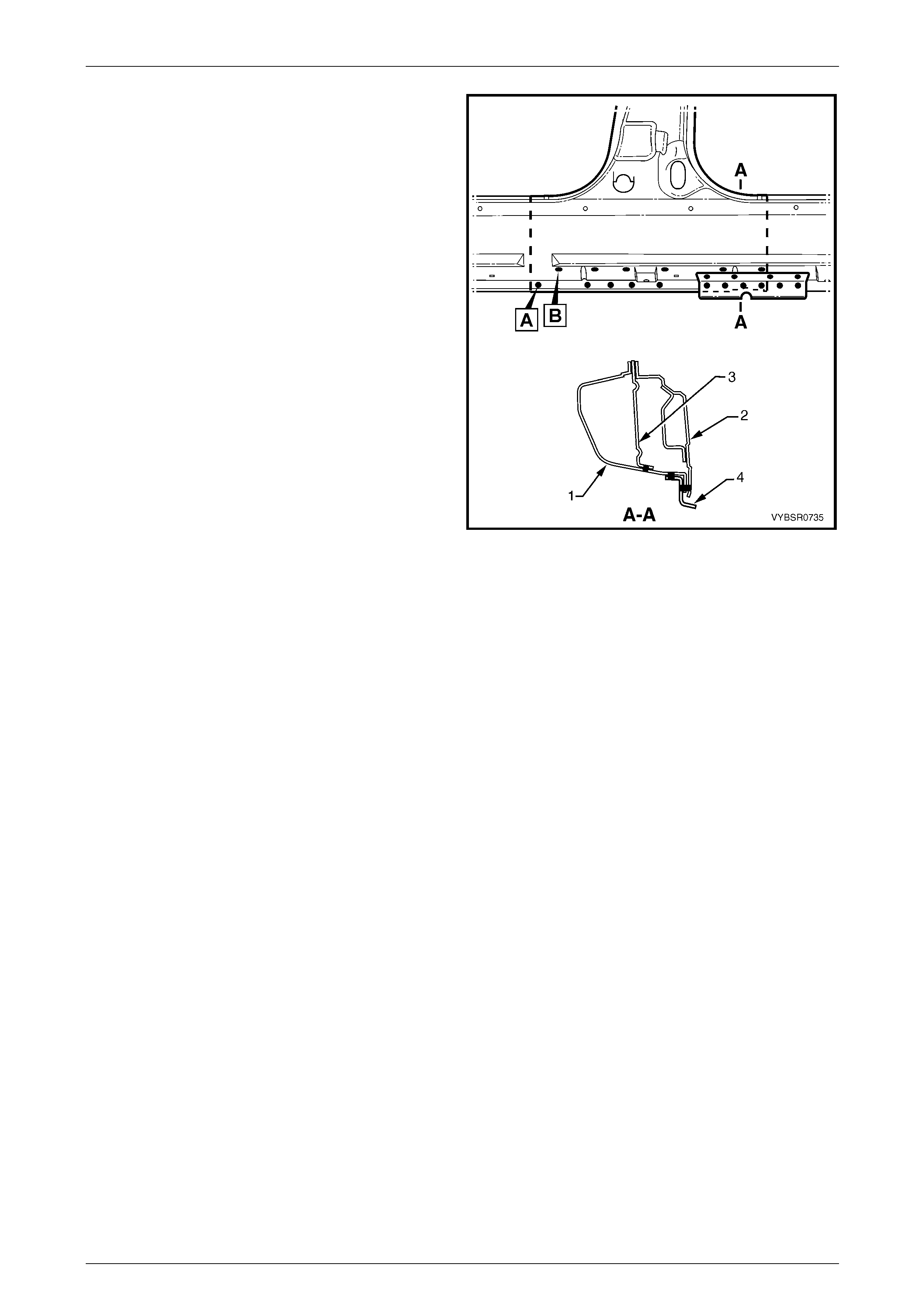
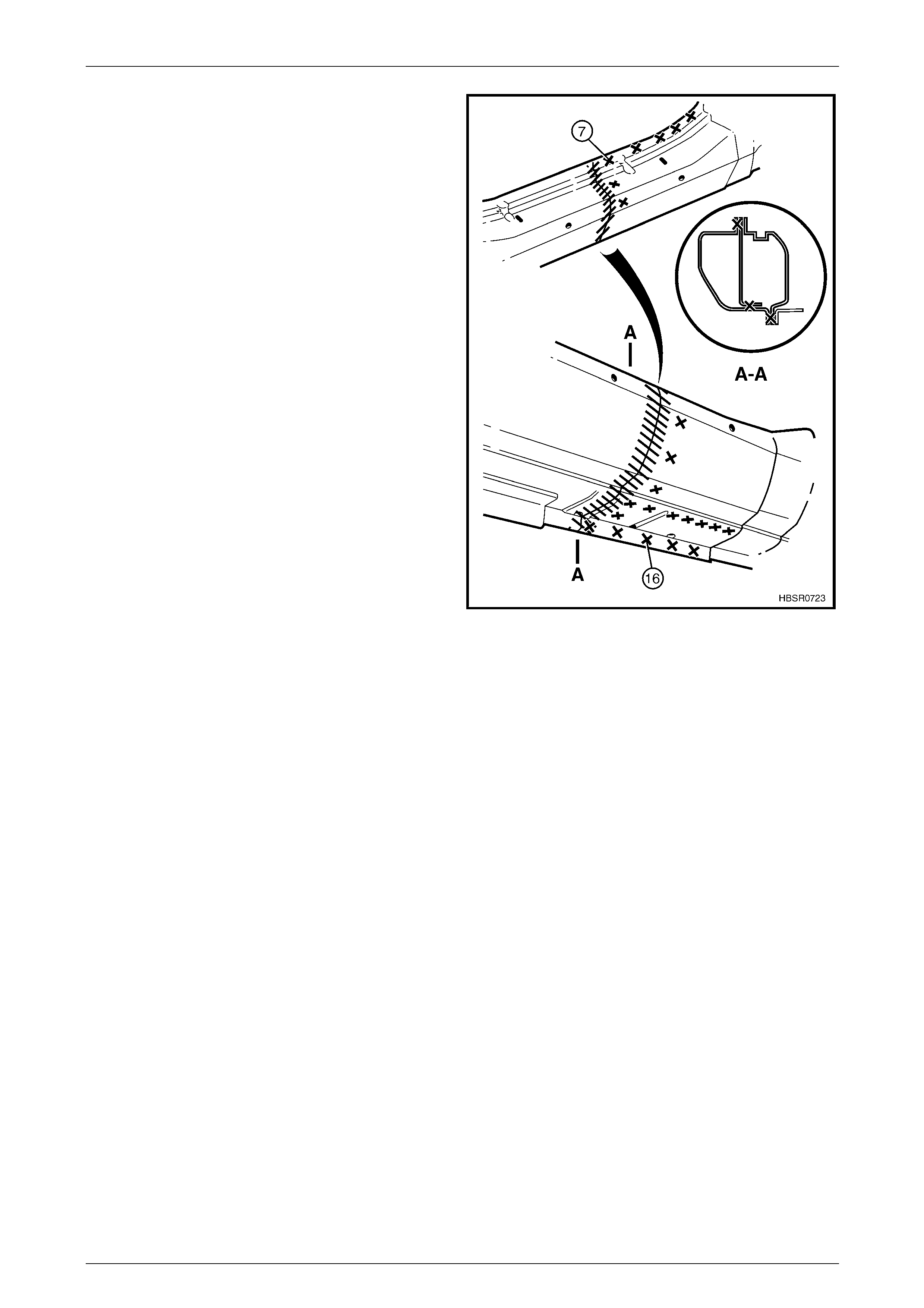
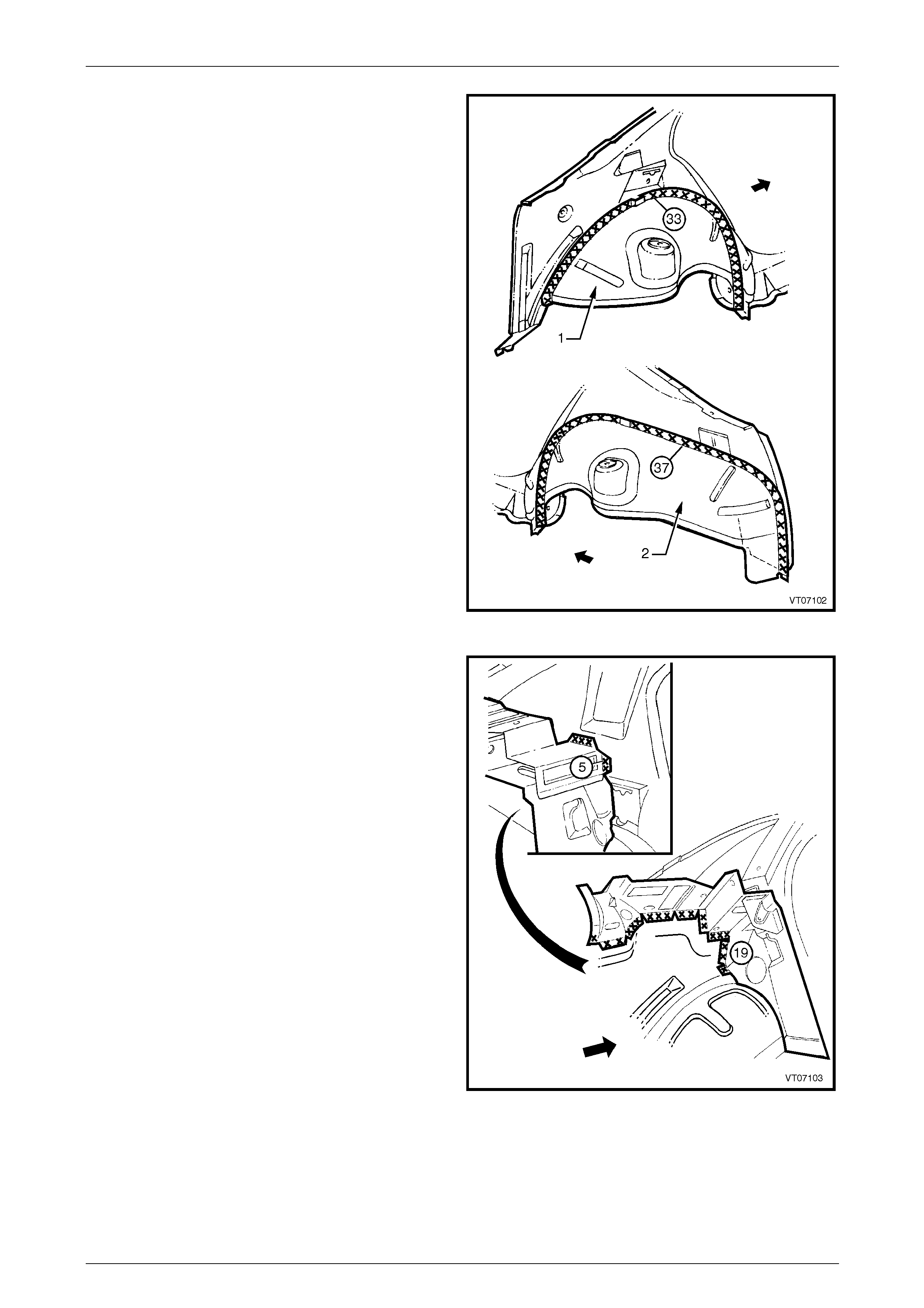
11 Spot cup the welds in three places (1) attaching the
quarter panel to the quarter panel inner asse mbly.
Using a saw or other appropr iate equipment, cut
through the rear quarter panel. The cut should pass
across the drain channel, then alo ng the inner face of
the quarter panel to the rear windscreen opening
flange as illustrated.
NOTE
It is important to leave enough material al ong the
inner face of the quarter panel (2) to facilitate a
lap joint of the old and new panels.
12 Remove the quarter panel from the vehicle, then repair
any damage to adjacent parts.
NOTE
For the right-hand side, break or cut the acrylic
spot weld sealer attaching the fuel filler cap
housing.
13 Check and rectify the alignment of the body as
required, refer to Section 3 Body Construction.
Figure 7 – 8
7 Body Side Page 7–7
Page 7–7
Replace
NOTE
Spot welding is the preferred method for
attaching of panels and should b e used whenever
possible. Where the spot welding equipment will
not access the required weld position, a plug
weld should be performed.
NOTE
The same number and position of spot welds (or
plug welds) should be used when replacing the
panel, as was used during manufacture, in order
to maintain the original structural strength of the
vehicle.
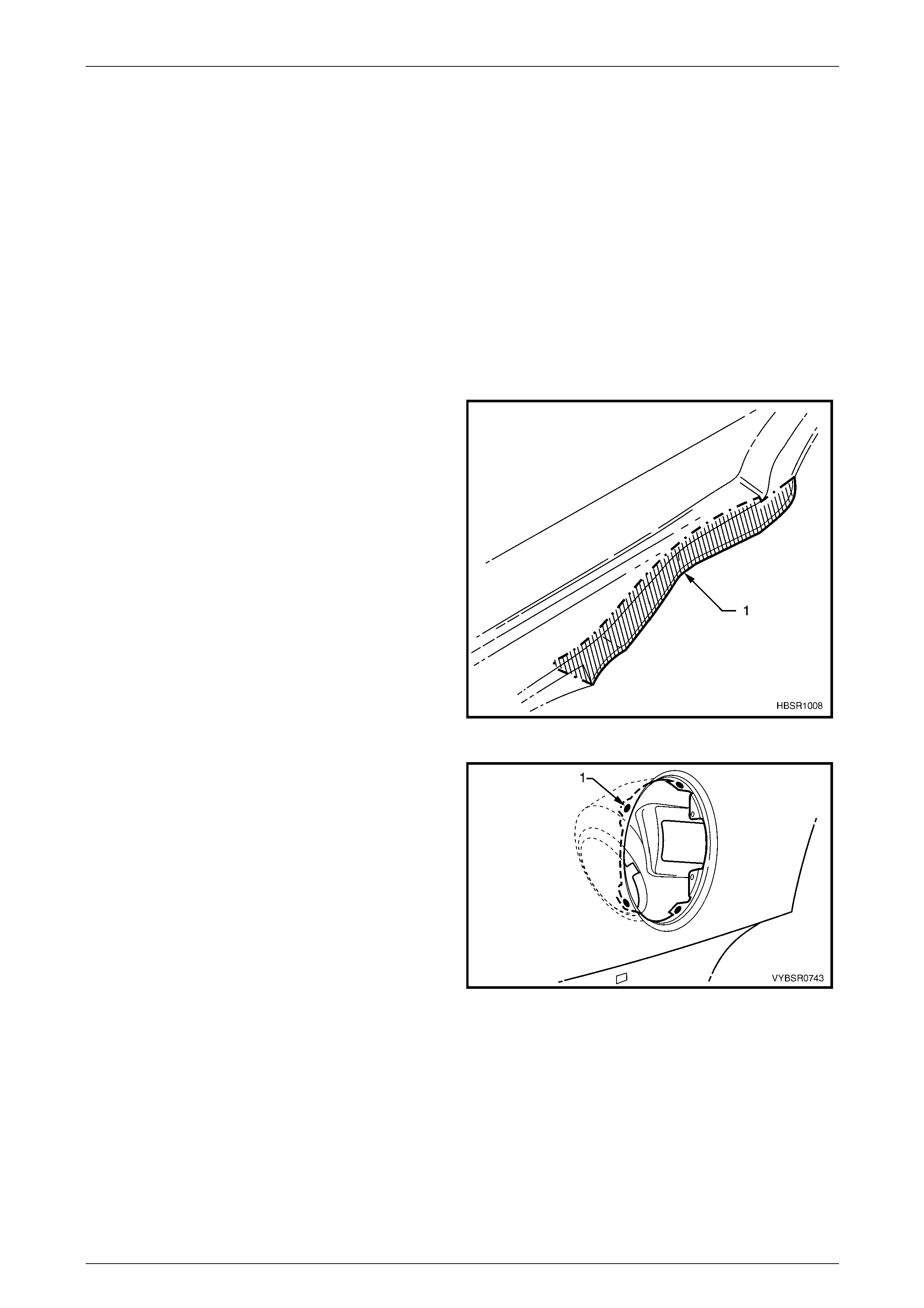
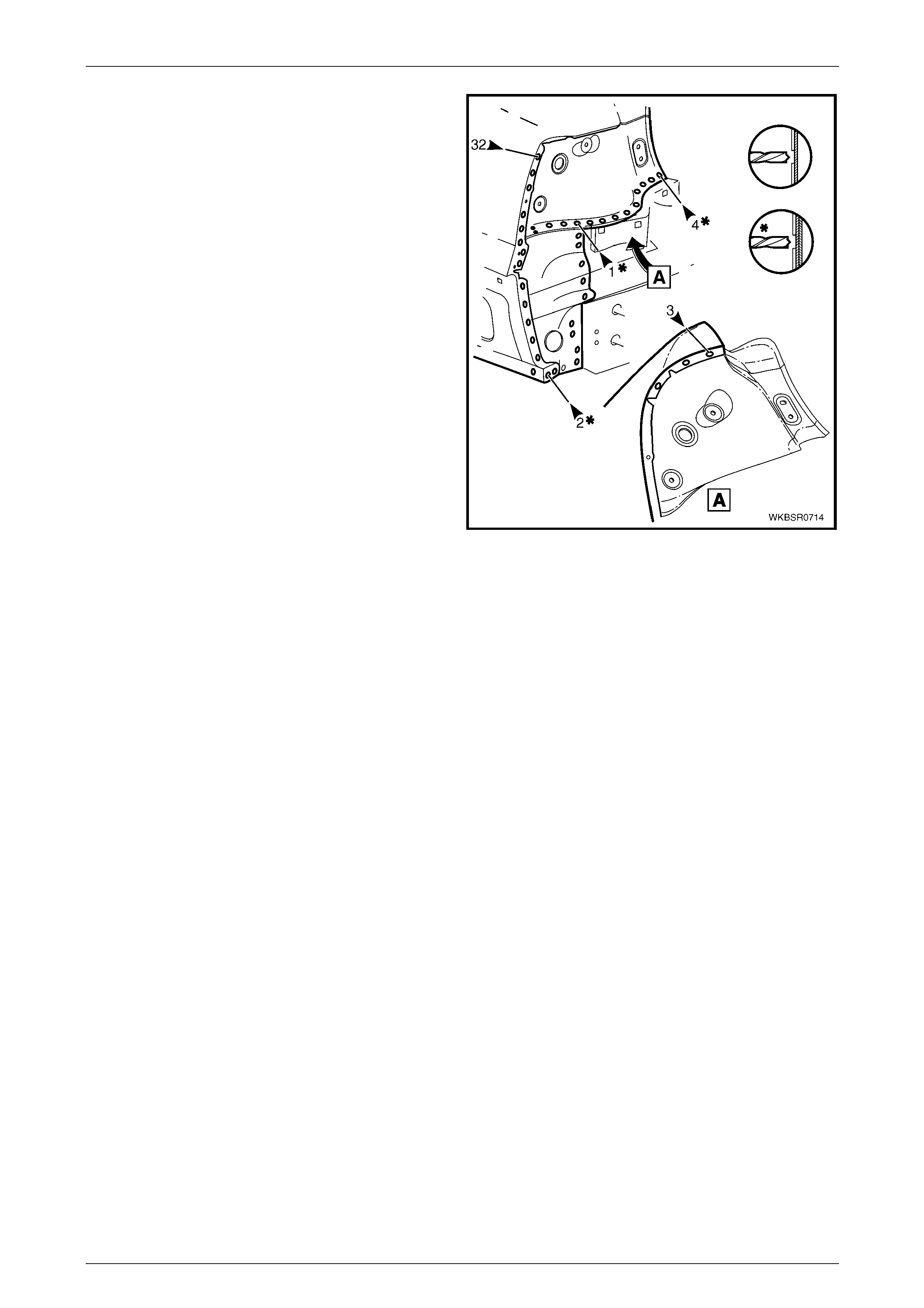
1 From the new quarter panel, cut and remove the
section (1) as shown to facilitate the join at the base of
the rear windscreen.
NOTE
Some replacement procedures for surrounding
panels require this section of the rear quarter
panel remain intact.
2 Mark the new panel with drilling locations, in
preparation for plug welding. Drill holes as required.
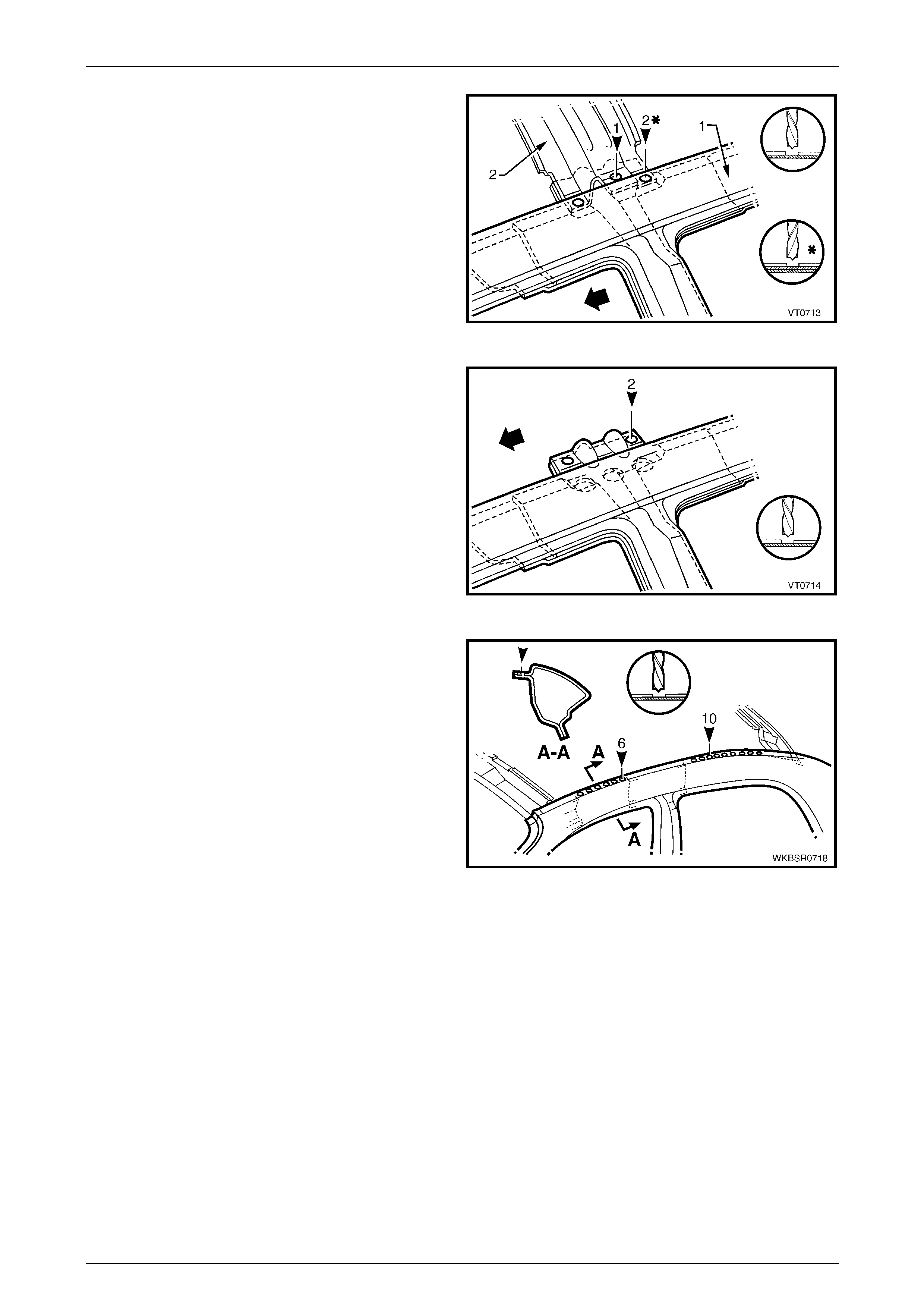
Figure 7 – 9
3 For the right-hand side, if required spot or plug
weld (1) the fuel filler pipe housing to the rear quarter
panel in four places.
4 Prepare all mating surfaces and treat with Weld
Through Primer (Item 1) as required except those
where Acrylic Spot Weld Sealer is to be used.
Refer to Section 3 Body Construction.
5 Apply Acrylic Spot Weld Sealer (Item 2) as required.
Refer to Section 3 Body Construction.
Figure 7 – 10
7 Body Side Page 7–8
Page 7–8
6 Fit and clamp the panel in position. Ensure the inner
face of the quarter panel at the base of the rear
windscreen (1) sits over the flange (2) as sh own.
NOTE
Ensure that a small gap exists along the
back body pillar braze joint and all margins
with adjacent panels are even and within
the tolerances specified in
Section 3 Body Construction.
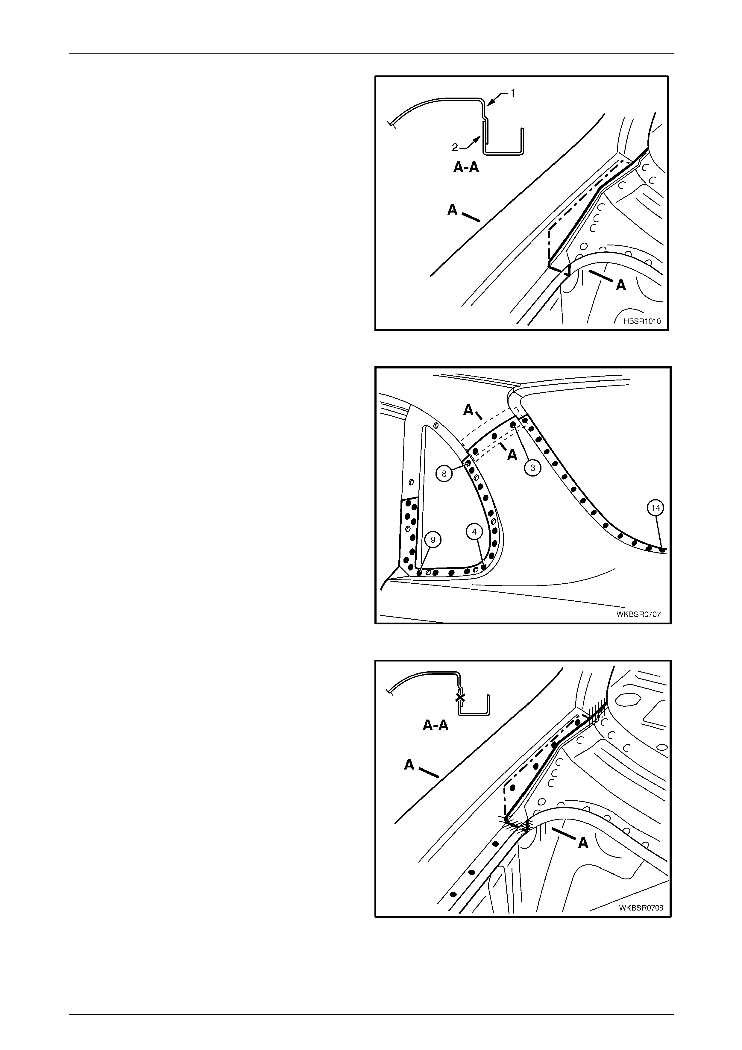
Figure 7 – 11
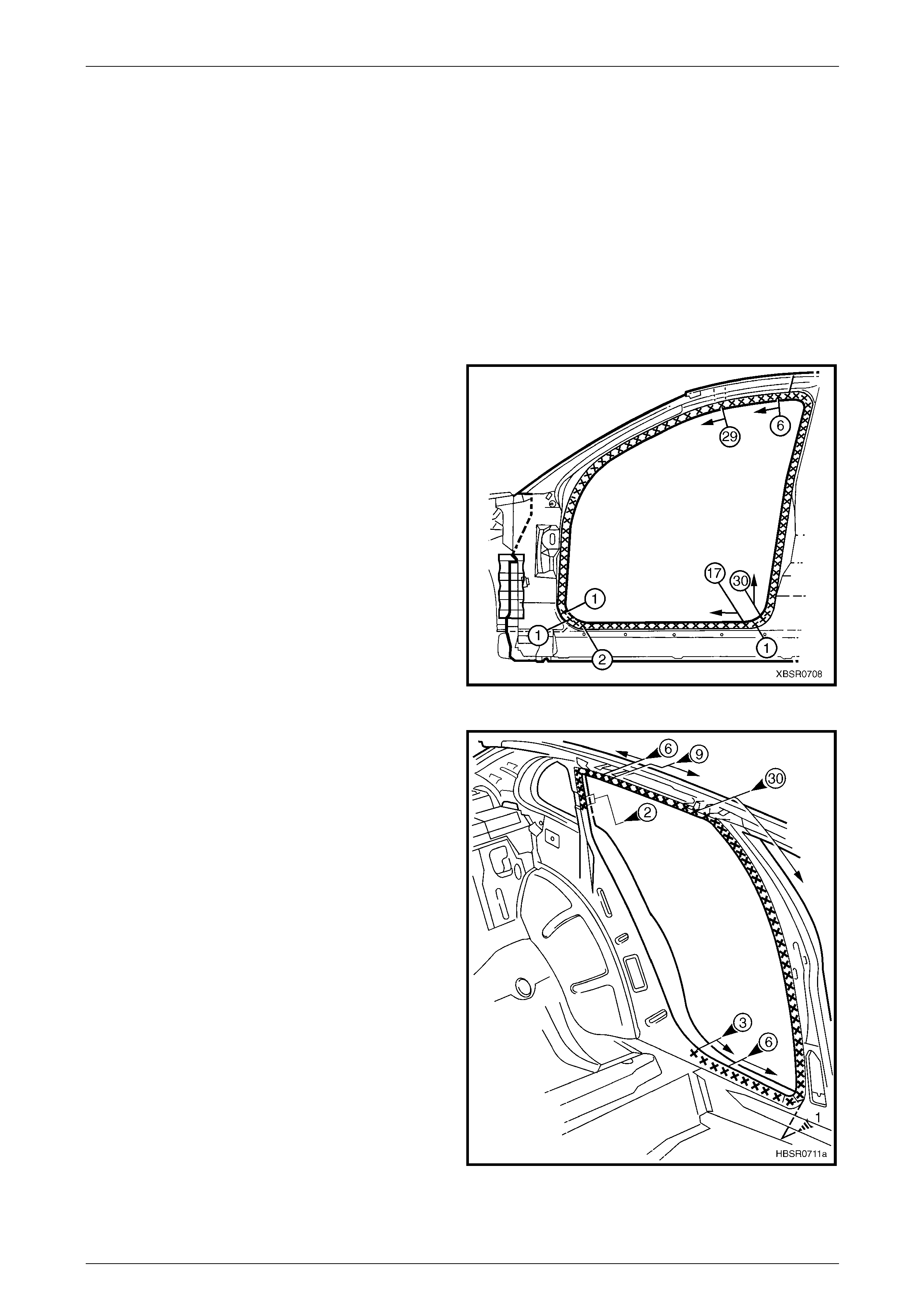
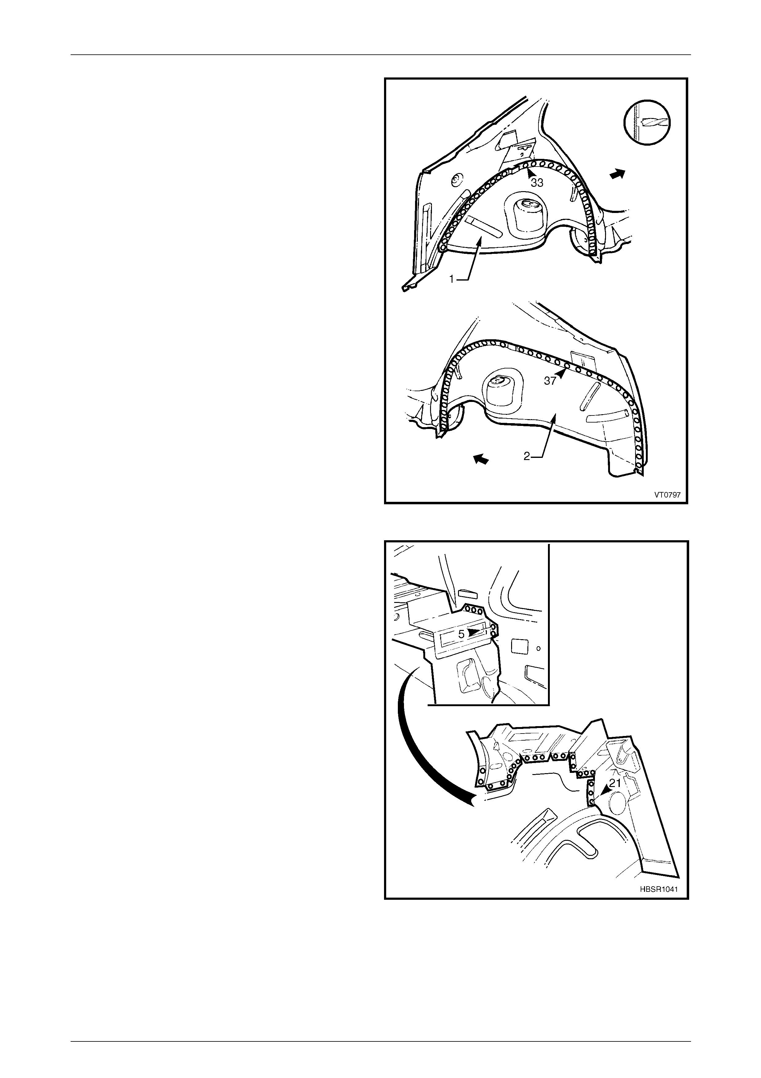
7 Spot or plug weld the panels along the side glass
opening flange, braze joint reinforcement and rear
windscreen flange as shown.
Figure 7 – 12
8 Spot or plug weld in three places the quarter panel to
the quarter panel inner assembly and the lap join in
four places.
9 Butt weld across the drain channel and windscreen
opening flange.
Figure 7 – 13
7 Body Side Page 7–9
Page 7–9
10 Spot or plug weld the rear quarter panel to the door
opening frame.
Figure 7 – 14
11 Spot or plug weld the rear quarter panel to the quarter
panel inner assembly ar ound the wheel arch openin g.
Figure 7 – 15
12 Spot or plug weld the lower edge of the quarter panel
to the rear compartment floor panel outer extension.
13 Apply Acrylic Spot Weld Sealer (Item 2) as required to
the tail lamp housing, quarter pan el upper extension
and quarter panel lower extension.
Refer to Section 3 Body Construction.
14 Clamp in position the tail lamp housing, quarter panel
upper extension and quarter panel lower extension
and spot or plug weld to the quarter panel and rear
end panel lower. Refer to 2.2 Tail Lamp Housing,
Quarter Panel Lower Extension and Quarter Panel
Upper Extension – Repl ace.
Figure 7 – 16
7 Body Side Page 7–10
Page 7–10
15 Prepare the braze joint across the back body pillar.
Apply wet rags each side of the join to minimi se heat
distortion and carefully MIG braze across the pillar as
shown. Ensure the surfaces are flush, rework and
finish as required.
NOTE
Temporarily fit the side quarter glass to e nsure it
fits flush along the back body pillar and the
correct seal tension is achieved. Also check
along the rear windscreen edge for straightness.
26 Refinish and paint panels and other components as
required. Refer to Section 3 Body Construction .
Figure 7 – 17
17 Add a bead of Joint Sealer to the lap j oint at the base
of the rear windscreen as shown.
18 Apply Joint Sealer (Item 3) as required.
Refer to Section 3 Body Construction.
19 Apply Cavity Wax (Item 8) as required to the inside of
any box sections or area i naccessible to paint.
Refer to Section 3 Body Construction.
20 Replace the adjacent bolt on p anels and components
as described in the appropriate Section of the MY2005
WL Service Information.
Figure 7 – 18
7 Body Side Page 7–11
Page 7–11
2.2 Tail Lamp Housing, Quarter Panel Lower
Extension and Quarter Panel Upper
Extension – Replace
To avoid the possibility of fire, take particular
care when cuttin g or w elding at the rear of the
vehicle. Remove the fuel tank and plug all fuel
lines.
Remove
NOTE
The components descri bed in this pr ocedure may
be replaced as an assembly or individually as
required.
1 Remove the adjacent bolt-on panels and components
as described in the appropriate Section of the MY2005
WL Service Information.
Figure 7 – 19
2 Remove the quarter panel upper extension by spot
cutting the welds attaching it to the quarter pane l and if
required, the tail lamp housing.
Figure 7 – 20
7 Body Side Page 7–12
Page 7–12
3 Remove the tail lamp housing by spot cutting the
welds attaching it to the rear quarter panel, rear end
lower panel, quarter panel lower extension and quarter
panel upper extension as require d.
4 Remove the quarter panel lower extension by spot
cutting the welds attaching it to the rear quarter panel
tail lamp housing and to the rear end lower panel as
required.
5 Remove the panel(s) from the vehicle, then re pair any
damage to adjacent parts.
Figure 7 – 21
Replace
NOTE
• Spot welding is the preferred method for
attaching of panels and should be used
whenever possible. Where the spot welding
equipment available will not access the
required weld position, a plug weld should be
performed.
• The same number and p ositio n of spot or pl u g
welds should be used when replacing the
panel, as was used during manufacture, in
order to maintain the original structural
strength of the vehicle.
1 Mark the new panels with drilling locati ons, in preparation for plug welding where required. Drill holes as requir ed.
2 Prepare all mating surfaces and treat with Weld Through Primer (Item 1) as required except where Acrylic Spot
Weld Sealer is to be applied. Refer to Section 3 Body Construction.
3 Apply Acrylic Spot Weld Sealer (Item 2) as required. Refer to Section 3 Body Constructio n.
7 Body Side Page 7–13
Page 7–13
4 Fit and clamp the removed panels into position.
5 Temporarily fit the tail lamp and ensur e its correct
fitment and alignment to the adjacent panels.
6 Spot or plug weld the quarter panel lower extension
into position as requir ed, attaching it to the quarter
panel, tail lamp housing and rear end lower panel.
7 Spot weld the tail lamp housing to the quarter panel,
rear end lower panel, quarter panel lower extension
and quarter panel upper extensio n.
Figure 7 – 22
8 Spot weld the quarter panel upper extension to the
quarter panel and to the tail lamp housing.
9 Refinish and paint panels and other components as
required. Refer to Section 3 Body Construction .
10 Apply Joint Sealer (Item 3) as required.
Refer to Section 3 Body Construction.
11 Apply Cavity Wax (Item 8) as required to the inside of
any box sections or areas i na ccessible to paint.
Refer to Section 3 Body Construction.
12 Replace the adjacent bolt on p anels and components
as described in the appropriate Section of the MY2005
WL Service Information.
Figure 7 – 23
7 Body Side Page 7–14
Page 7–14
2.3 Door Opening Frame Assembly –
Replace
NOTE
• This procedure requires the removal of the
roof panel. As an alternative, the door
opening frame assembly can be cut at the
upper pillar sections by following the
procedures in 2.4 Door Opening Frame
Assembly – Partial Replace, Hinge Pillar,
2.5 Door Opening Frame Assembly – Partial
Replace, Centre Pillar and
2.6 Door Opening Frame Assembly – Partial
Replace, Body Lock Pillar.
• Cavity Foam is used within the hinge, centre
and lock pillar cavities. Care is required when
repairing the vehicle in these areas, refer to
Section 2 Precautions prior to beginning any
work for further information.
Remove
1 Remove the adjacent bolt-on panels and components
as described in the appropriate Section of the MY2005
WL Service Information.
2 Remove the windshield and the rear window
assemblies, refer to Section 1A6 Stationary Windows
in the MY2005 WL Service Information.
3 Remove the dash panel retaining bolt from the hinge
pillar.
4 Remove the roof panel, refer to Section 9 Roof .
5 Remove the rear quarter panel, refer to
2.1 Rear Quarter Panel – Replace.
6 Remove the front wheelhouse pan el upper side rail,
refer to Section 4 Front End in the MY2005 WL
Service Information.
Figure 7 – 24
7 Spot cut the welds attaching the door opening frame
assembly to the inner rocker panel and to the hinge
pillar inner panel assembly.
NOTE
In order to spot cut the uppermost of these welds
it may be necessary to cut and peel back the
section of hinge reinforcement panel covering
the welds, to gain the required access.
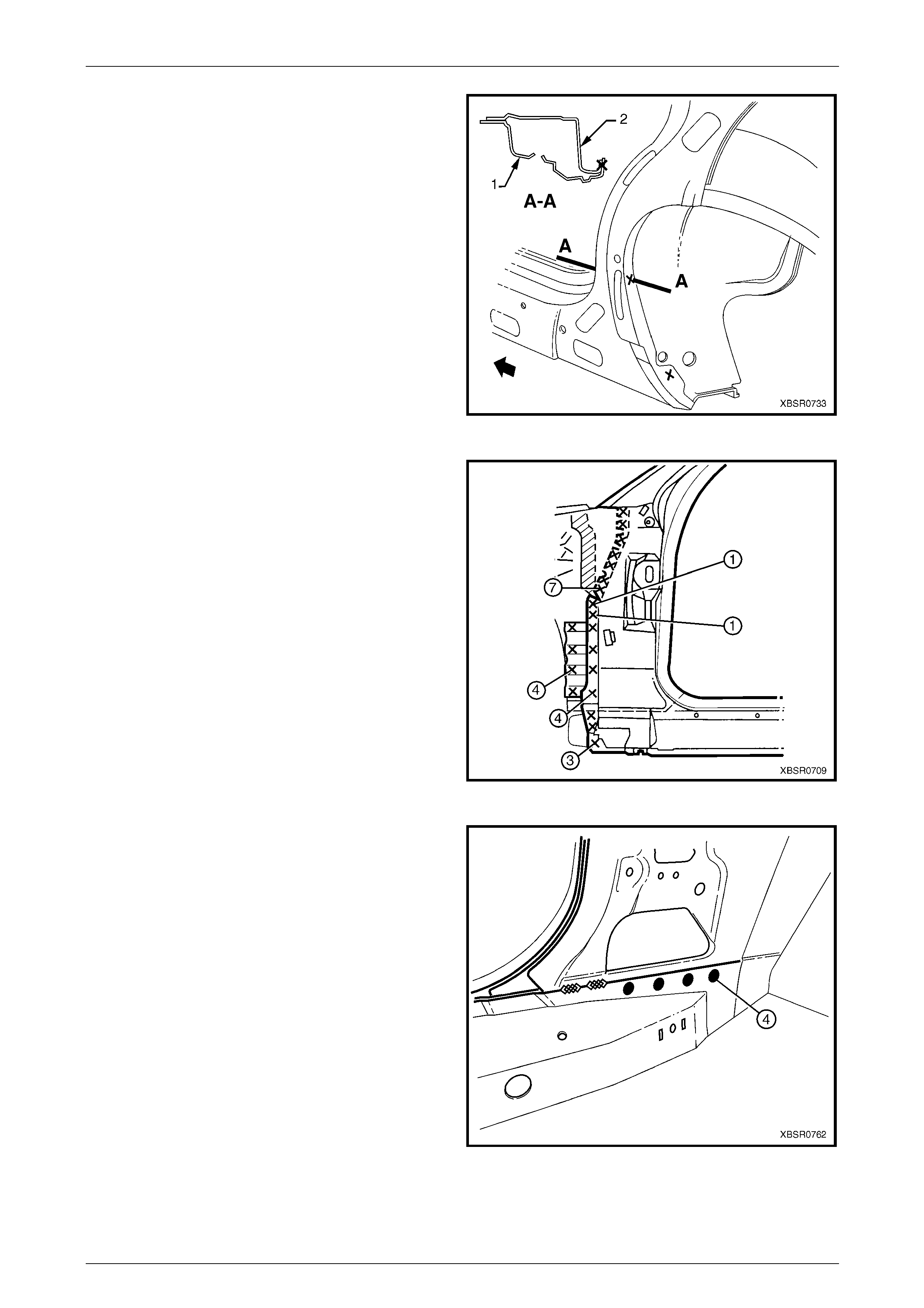
8 Spot cut the welds attaching the inner rocker panel (1)
and hinge pillar inner p anel assembly (2) to the rocker
panel reinforcement (3). Refer to Figure 7 – 2 6.
NOTE
It is not required to cut the MIG welds.
Figure 7 – 25
7 Body Side Page 7–15
Page 7–15
Figure 7 – 26
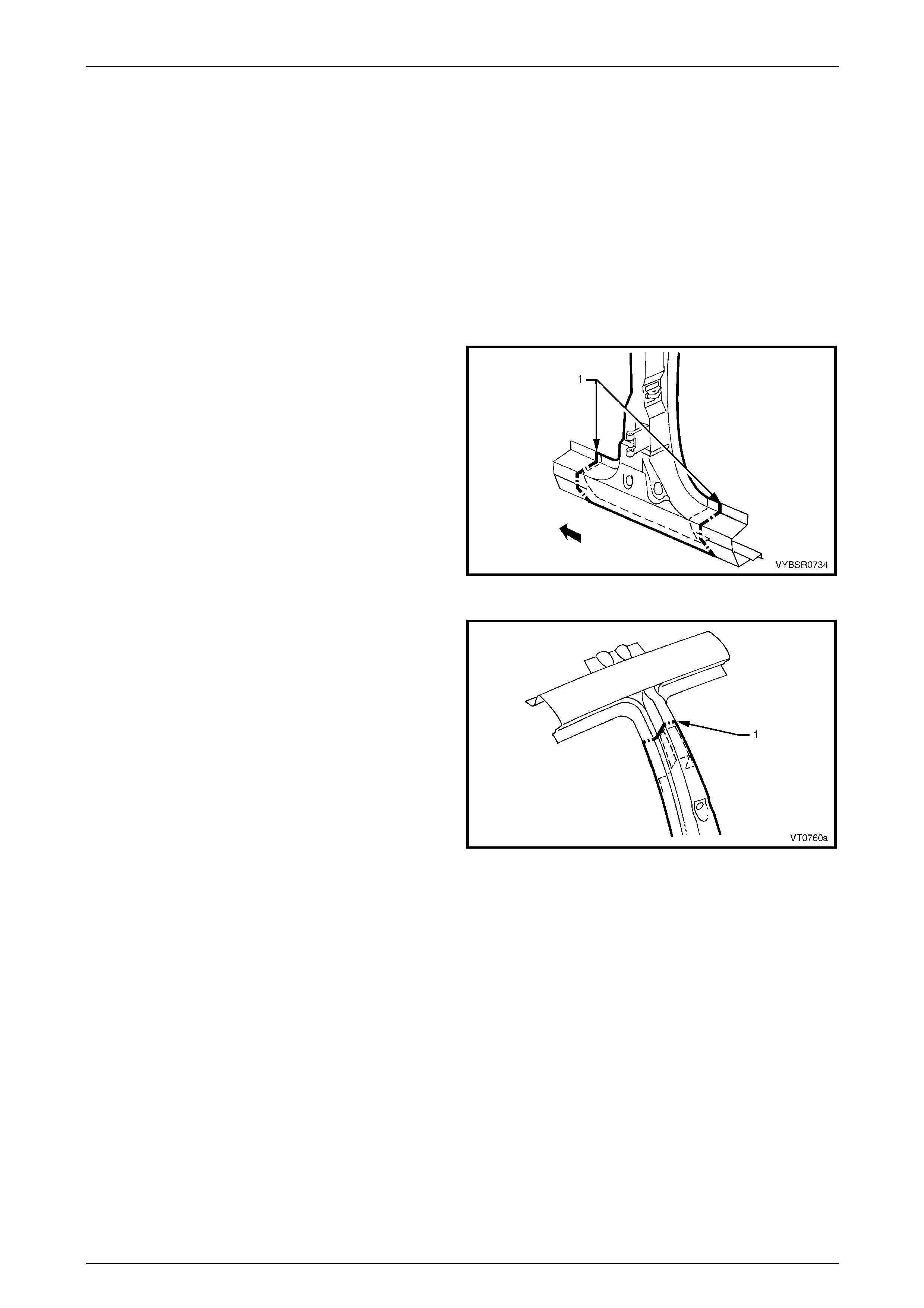
9 Spot cut the two welds at the base of the hinge pillar,
attaching the door opening frame assembly (1) to the
hinge pillar inner panel assembly (2).
Figure 7 – 27
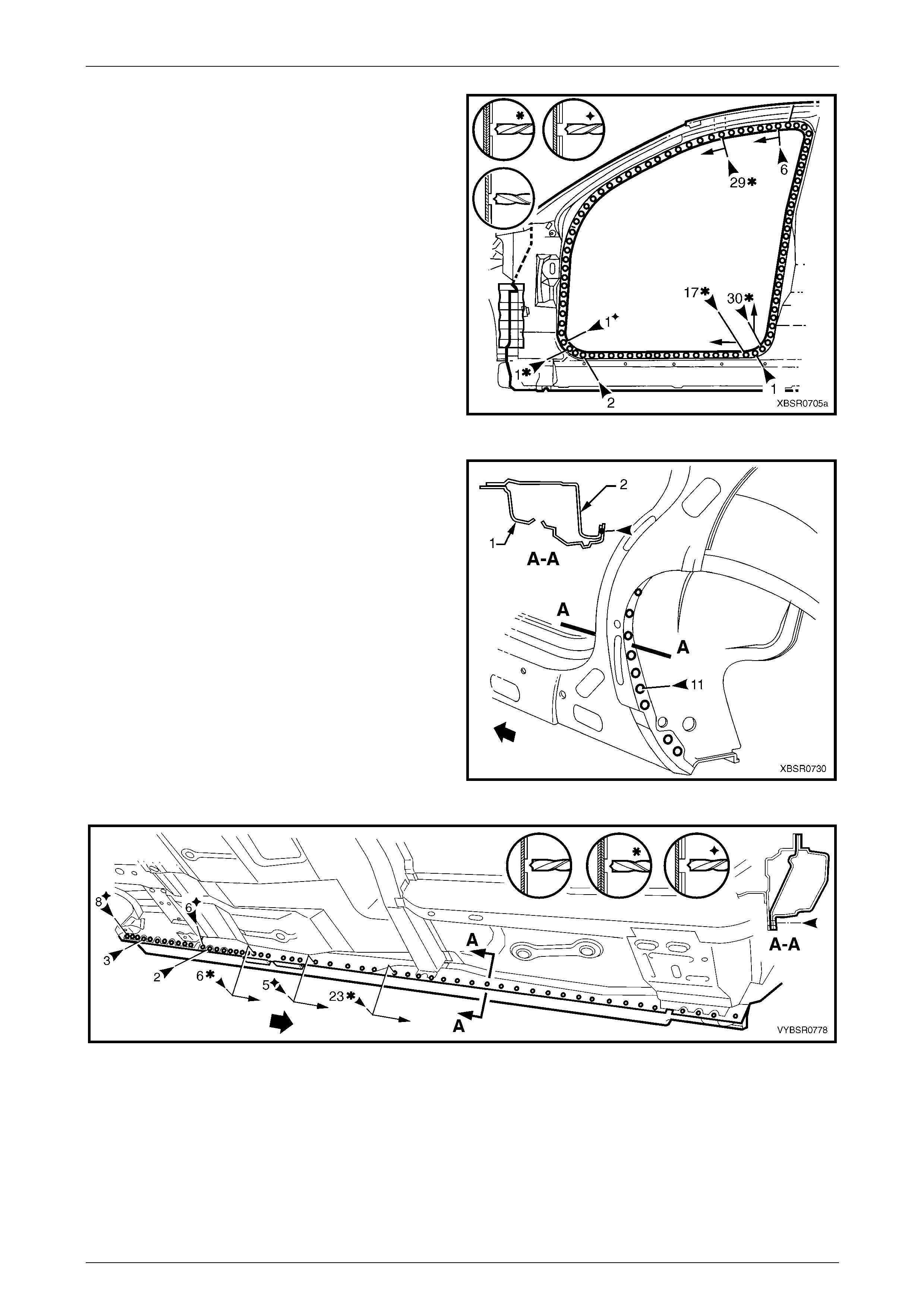
10 Spot cut the welds on the windshield side flange,
attaching the door opening frame assembly (1) to the
hinge pillar inner panel assembly (2).
Figure 7 – 28
7 Body Side Page 7–16
Page 7–16
11 Spot cut the welds on the flange surrounding the front
door opening, attaching the door op ening frame
assembly to the hinge pillar inner panel assembly,
inner rocker panel and quarter panel inner assembly.
Figure 7 – 29
12 Spot cut the welds around the rear wheel arch joining
the door opening frame assembly (1) to the quarter
panel inner assembly (2).
NOTE
Many may have been removed with the rear
quarter panel.
13 Spot cut along the vertical flange below the rocker
panel to separate the door opening frame assembly
from the inner rocker panel and rear floor p an el outer
extension. Refer to F igure 7 – 31.
Figure 7 – 30
Figure 7 – 31
7 Body Side Page 7–17
Page 7–17
14 Spot cut from below, up into the rocker panel, to separate the welds attaching the door opening frame assembly to
the quarter panel inner assembl y, refer to Figure 7 – 32.
Figure 7 – 32
15 Spot cut the welds around the rear door opening
flange.
Figure 7 – 33
16 Spot cut the welds along the rear side window and
rear window flange attaching the door opening frame
assembly (1) to the quarter panel inner assembl y (2).
Figure 7 – 34
7 Body Side Page 7–18
Page 7–18
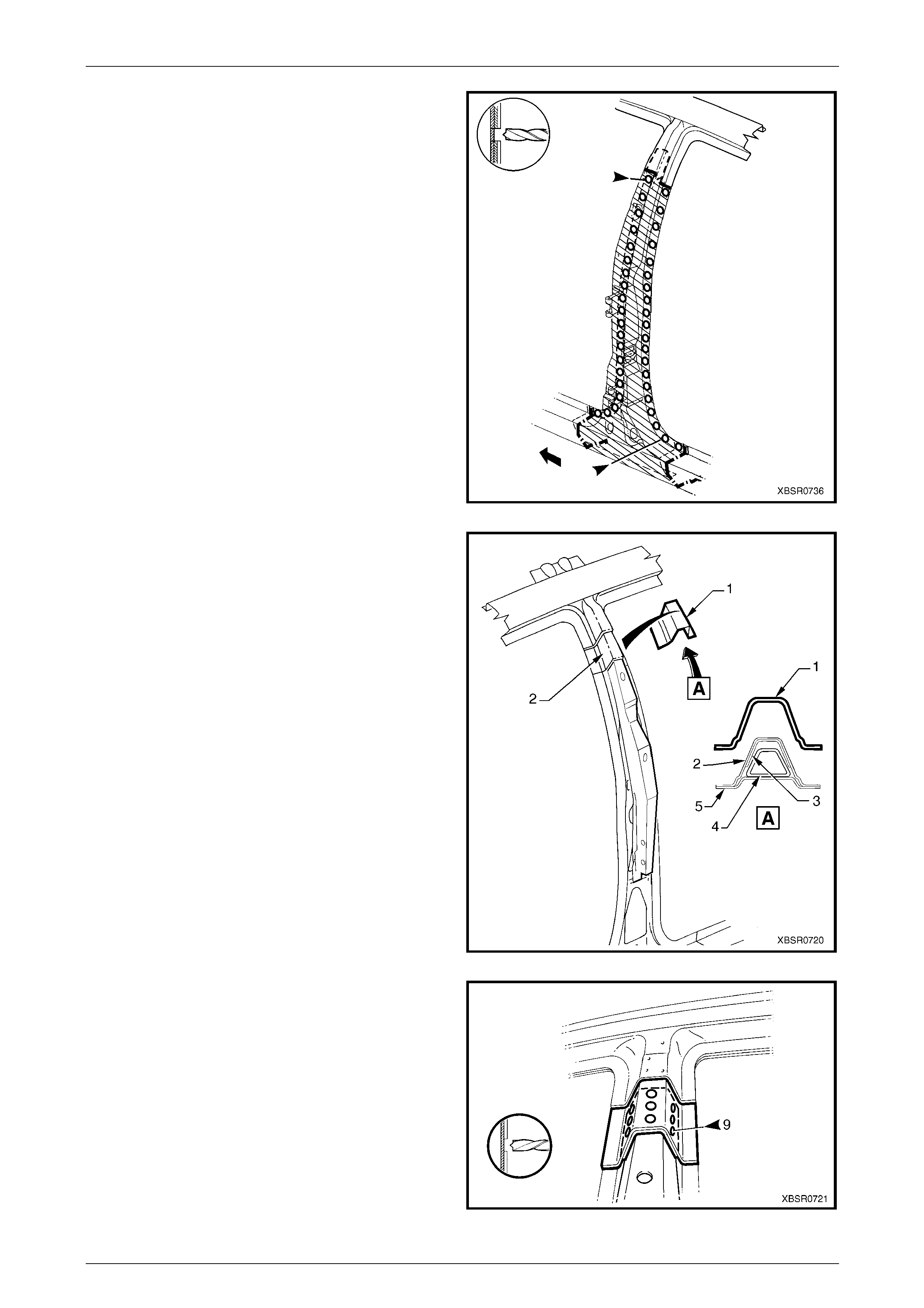
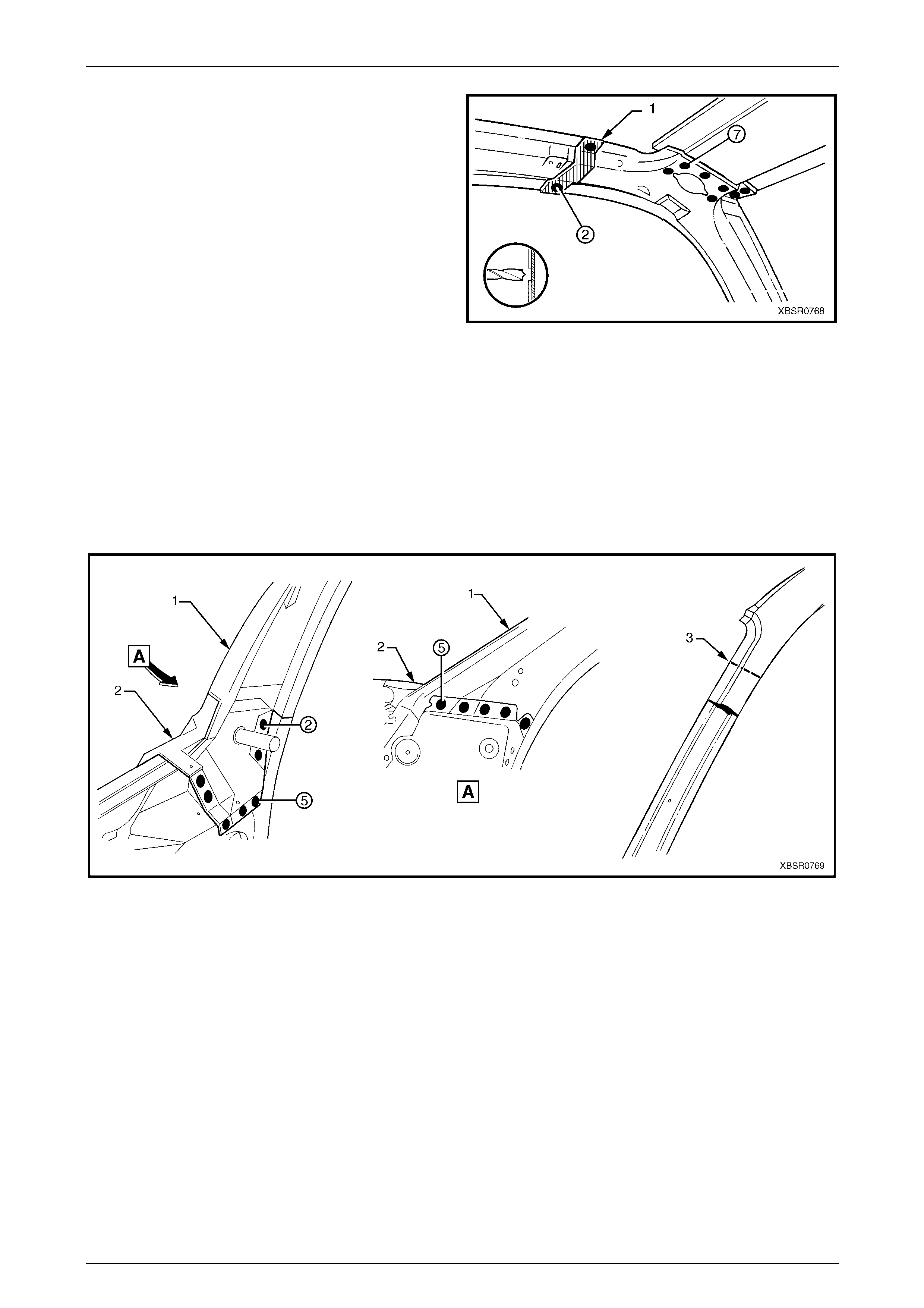
17 Spot cut the two welds attaching the roof bow
panel (2) to the centre pillar upper reinforcem ent, and
the single weld attaching the roof bow panel to the
door opening frame assembly (1).
NOTE
Model without sunroof shown, for models with
sunroof, the housing has welds in the same
locations.
Figure 7 – 35
18 Carefully lifting the roof bow panel out of the way, spot
cut the two welds attaching the centre pillar upper
reinforcement to the quarter panel inner asse mbly.
The centre pillar upper reinforcement is removed as
part of the door opening frame assembl y.
Figure 7 – 36
19 Spot cut the welds along the roof flange, attaching the
door opening frame assembly to the quarter panel
inner assembly.
NOTE
Many welds may have been removed with the
roof panel.
20 Remove the complete door opening frame assembly
and repair any dama ge to adjacent parts.
21 Check and rectify the alignment of the body as
required, refer to Section 3 Body Construction.
Figure 7 – 37
7 Body Side Page 7–19
Page 7–19
Replace
NOTE
• Spot welding is the preferred method for
attaching of panels and should be used
whenever possible. Where the spot welding
equipment available will not access the
required weld position, a plug weld should be
performed.
• The same number and position of spot welds
(or plug welds) should be used when
replacing the panel, as was used during
manufacture, in order to maintain the original
structural strength of the vehicle.
1 As required, mark the new panel with drilling locations
in preparation for plug welding. Drill holes as required.
2 Prepare all mating surfaces and treat with Weld
Through Primer (Item 1) as required, refer to
Section 3 Body Construction.
3 Apply Acrylic Spot Weld Sealer (Item 2), refer to
Section 3 Body Construction.
4 Securely clamp the door openin g frame assembly in
position on the vehicle body.
5 Begin attaching the door ope ning frame assembly by
spot welding around the front door opening flange.
Figure 7 – 38
6 Spot weld around the flange of the rear door opening
flange.
Figure 7 – 39
7 Body Side Page 7–20
Page 7–20
7 Spot or plug weld in two places around the rear wheel
arch, attaching the door opening frame assembly to
the quarter panel inner assembl y.
NOTE
These welds will be completed when the rear
quarter panel is replaced.
Figure 7 – 40
8 Spot or plug weld the door openi ng frame assembly to
the inner rocker panel and to the hinge pillar inner
panel assembly. If the sheetmetal was modified to
allow access to these welds, it should be repaired to
its original configuration.
Figure 7 – 41
9 Plug weld the inner rocker panel and hinge pillar inner
panel assembly to the rocker panel reinforce m ent.
Figure 7 – 42
7 Body Side Page 7–21
Page 7–21
10 Spot or plug weld the door openi ng frame
assembly (1) to the hinge pillar inner pa nel
assembly (2) at the base of the hinge pill ar.
Figure 7 – 43
11 Spot or plug weld the rear side window and rear
windscreen flanges to the door ope ning frame
assembly and to the quarter pane l inner assembly.
Figure 7 – 44
12 Spot or plug weld along the windshield flange,
attaching the door opening frame assembly (1) to the
hinge pillar inner panel assembly (2).
Figure 7 – 45
7 Body Side Page 7–22
Page 7–22
13 Spot or plug weld the door openi ng frame
assembly (1) to the quarter inner panel asse mbly, then
spot or plug weld the roof bow panel (2) to the door
opening frame assembly as shown.
NOTE
Model without sunroof shown, for models with
sunroof, the housing has welds in the same
locations.
Figure 7 – 46
14 Spot or plug weld the door openi ng frame assembly to
the quarter inner panel assembly along the roof panel
flange. Complete this flange when installing the roof
panel.
15 Spot or plug weld the door openi ng frame assembly
along the vertical flange below the rocker panel,
refer to Figure 7 – 48.
Figure 7 – 47
Figure 7 – 48
7 Body Side Page 7–23
Page 7–23
16 Plug weld up through the rocker panel to attach the door opening frame assembly to the quarter panel inner
assembly. Refer to Figure 7 – 49.
NOTE
Leave some welds until the rear quarter panel is
installed
Figure 7 – 49
17 Replace front wheelhouse panel upper side rail, refer to Section 4 Front End .
18 Replace the rear quarter panel, refer to 2.1 Rear Quarter Pane l – Replace.
19 Replace the roof panel, refer to Section 9 Roof.
NOTE
Refinish and prime any bare metal as required
prior to replacing these panel s.
20 Install the door hinges, refer to Section 8 Do ors.
21 Refinish and paint panels and other components as required. Refer to Section 3 Body Construction.
22 Apply Joint Sealer (Item 3) as required. Section 3 Body Construction.
23 Apply Cavity Wax (Item 8) as required to the inside of any box sections or areas inaccessible to paint,
refer to Section 3 Body Construction.
24 Apply Spray-on Deadener (Item 7) where applicab le, refer to Section 3 Body Construction.
25 Install the dash panel retaining bolt through the hinge pillar and tighten to the specified torque.
Dash panel retaining b olt
torque specification.................................35.0 – 45.0 Nm
26 Replace the windshield and the rear window assembly, refer to Section 1A6 Stationary Windo ws in the MY2005
WL Service Information.
27 Insert Cavity Foam into the hinge and ce ntre pillars as required, refer to Section 2 Precautions.
28 Install the remaining components as described in the appropriate Section of the MY2005 WL Service Information.
7 Body Side Page 7–24
Page 7–24
2.4 Door Opening Frame Assembly – Partial
Replace, Hinge Pillar
For vehicles fitted with an online sunroof the
hinge pillar must not be partially removed as
the sunroof drain tube is located in the pillar
and must not be cut. Refer to
2.3 Door Opening Frame Assembly –
Replace.
NOTE
Cavity Foam is used within the hinge, centre and
body lock pillar cavities. Care is required when
repairing the vehicle in these areas, refer to
Section 2 Precautions.
Remove
1 Remove the adjacent bolt-on panels and components
as described in the appropriate Section of the MY2005
WL Service Information.
2 Secure an appropriate tool between the front door
opening flanges to maintain correct bod y alignment.
3 Remove the windshield, refer to
Section 1A6 Stationary Windows in the MY2005 WL
Service Information.
4 Remove the dash panel retaining bolt from the hinge
pillar.
Figure 7 – 50
5 Remove the front wheelhouse pan el upper side rail,
refer to Section 4 Front End .
6 Spot cut the welds attaching the door opening frame
assembly to the inner rocker panel and to the hinge
pillar inner panel assembly.
NOTE
In order to spot cut the uppermost of these welds
it may be necessary to cut and peel back the
section of hinge reinforcement panel covering
the welds, to gain the required access.
7 Spot cut the welds attaching the inner rocker panel (1)
and hinge pillar inner p anel assembly (2) to the rocker
panel reinforcement (3). Refer to Figure 7 – 5 2.
NOTE
It is not required to cut the MIG welds.
Figure 7 – 51
7 Body Side Page 7–25
Page 7–25
Figure 7 – 52
8 Spot cut the two welds at the base of the hinge pillar,
attaching the door opening frame assembly (1) to the
hinge pillar inner panel assembly (2).
Figure 7 – 53
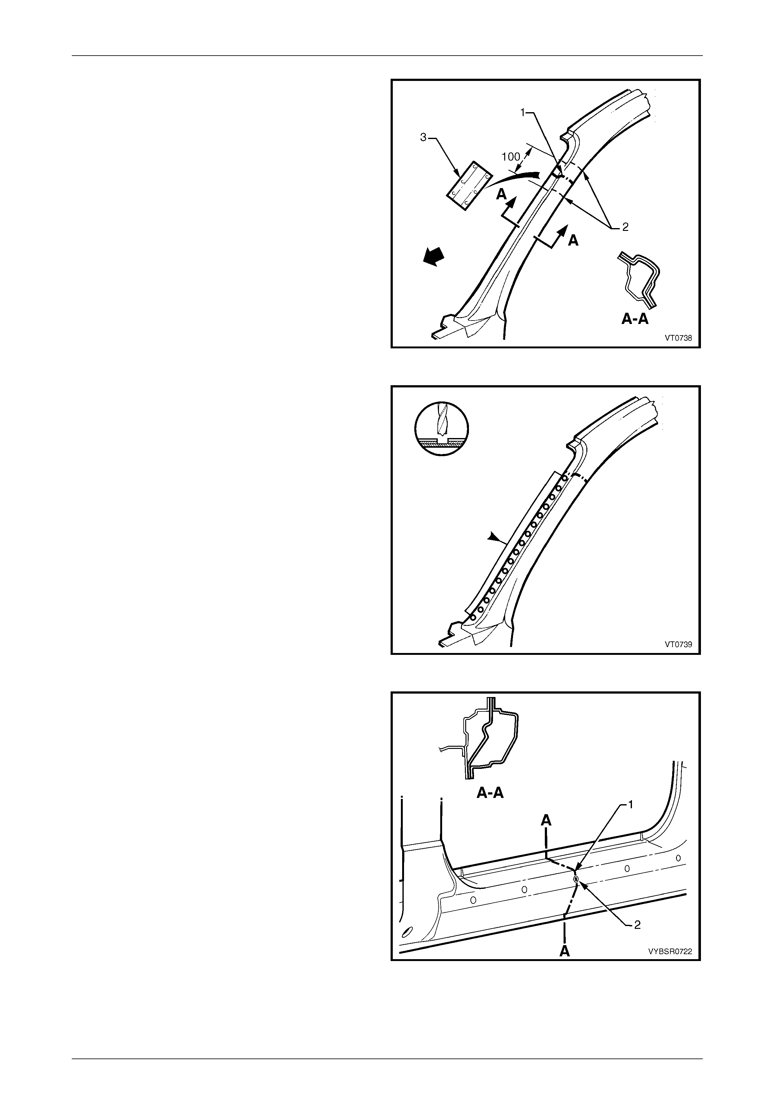
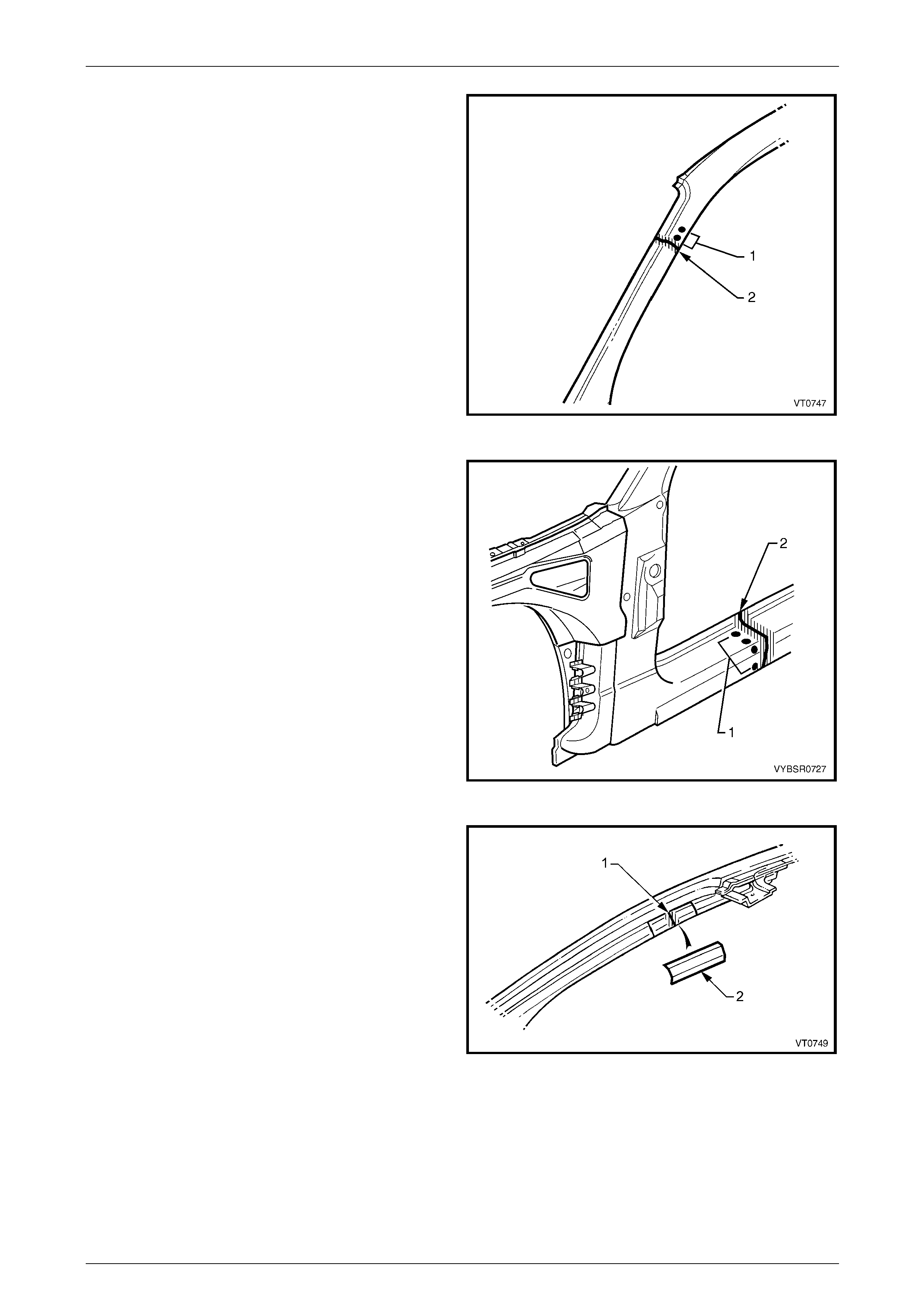
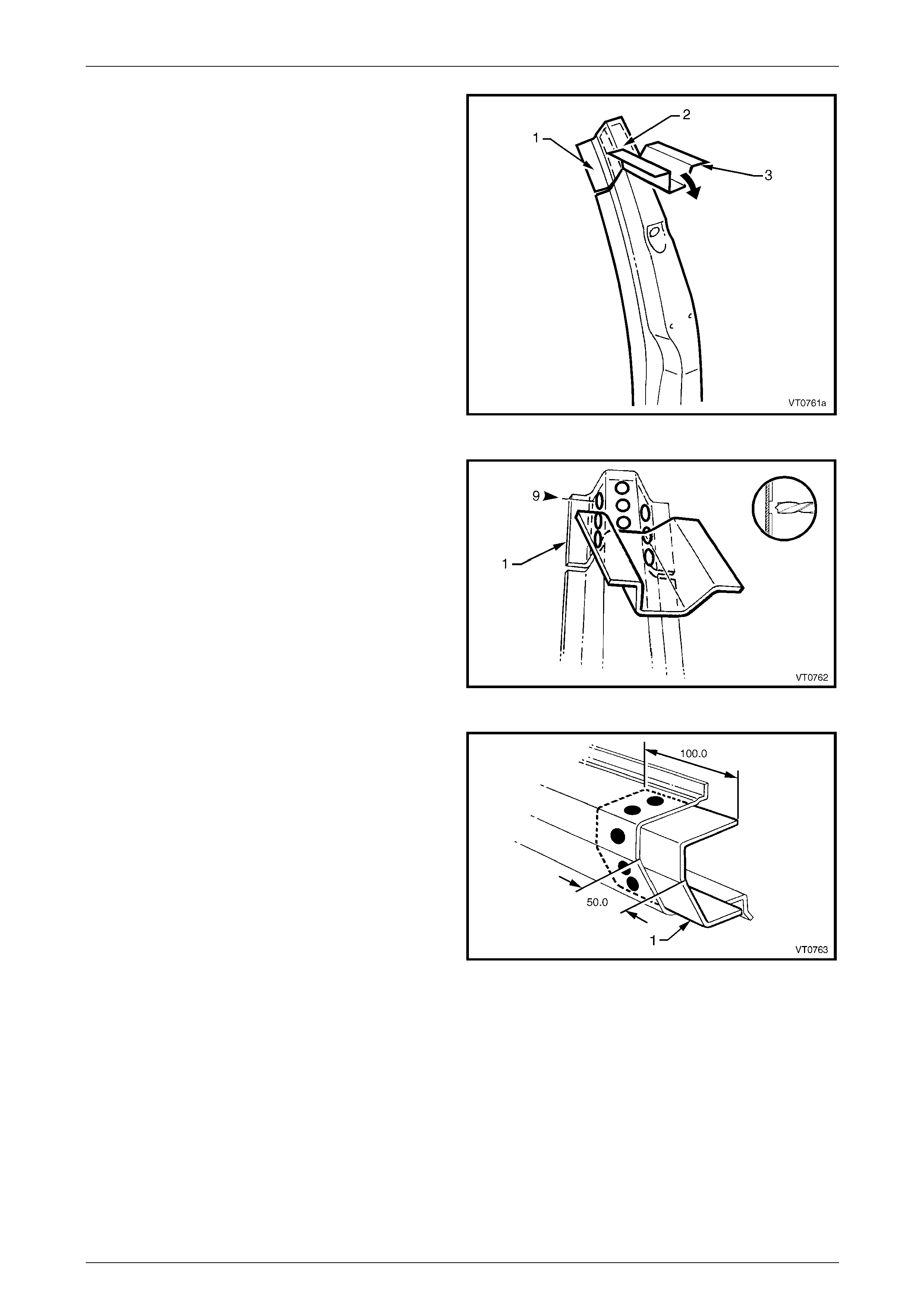
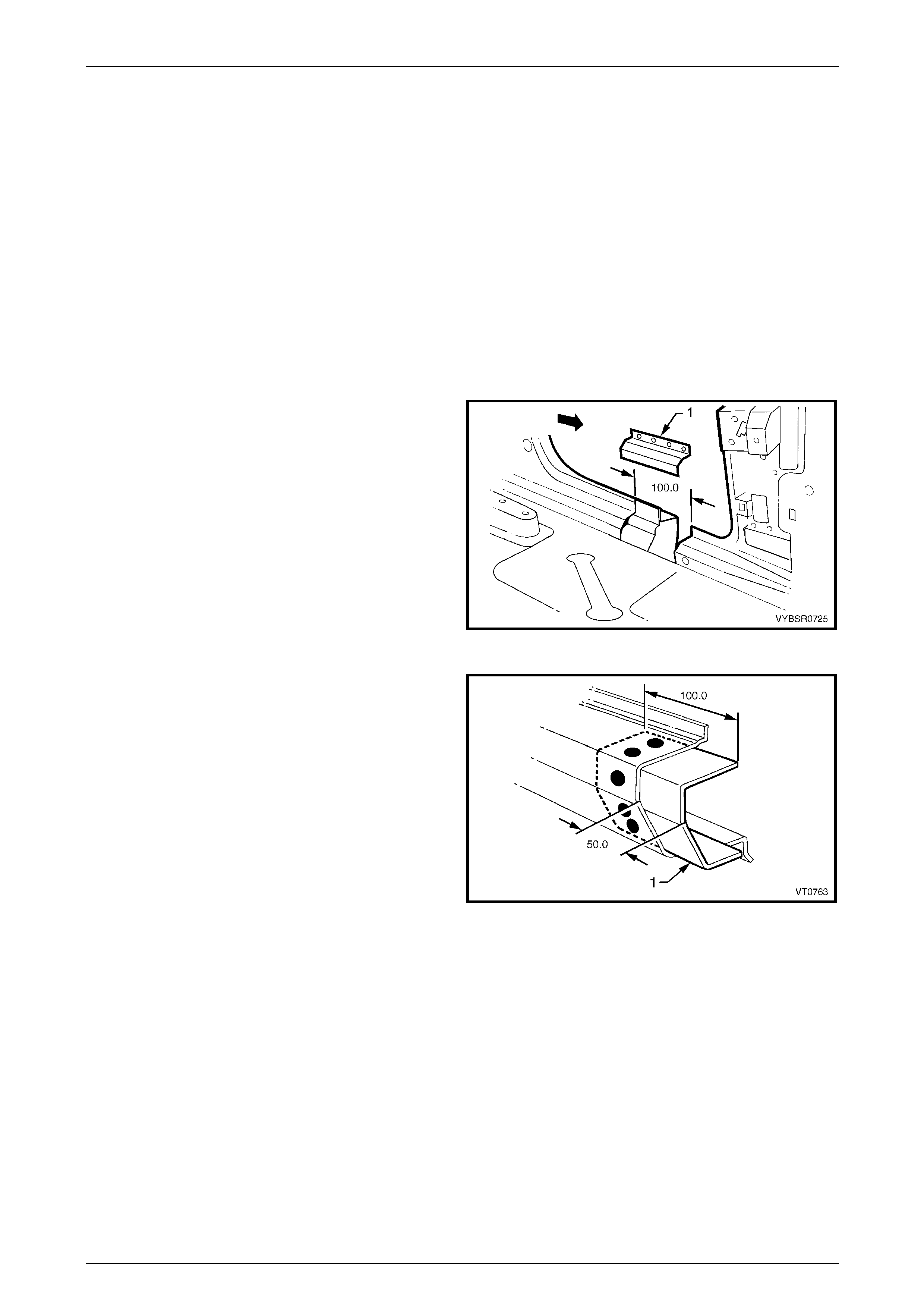
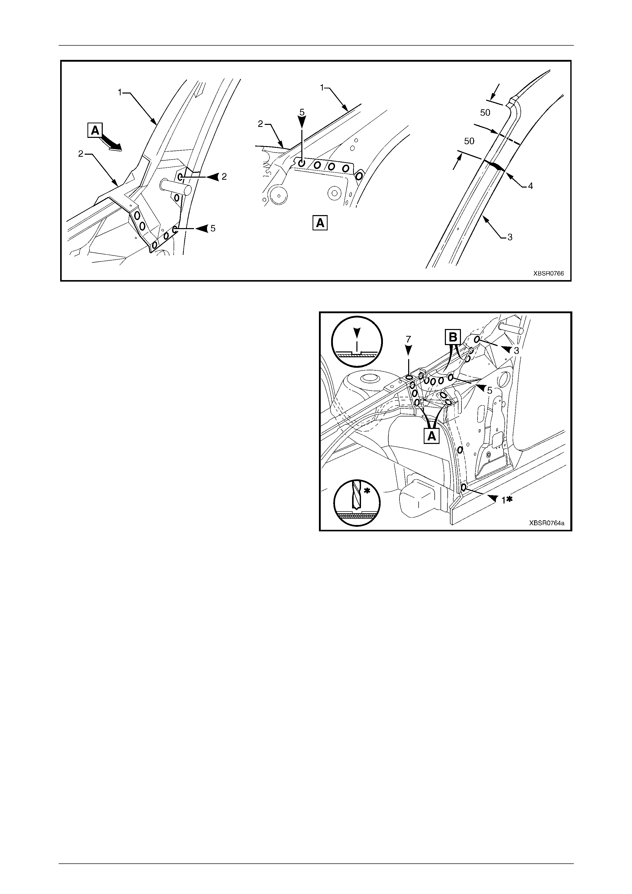
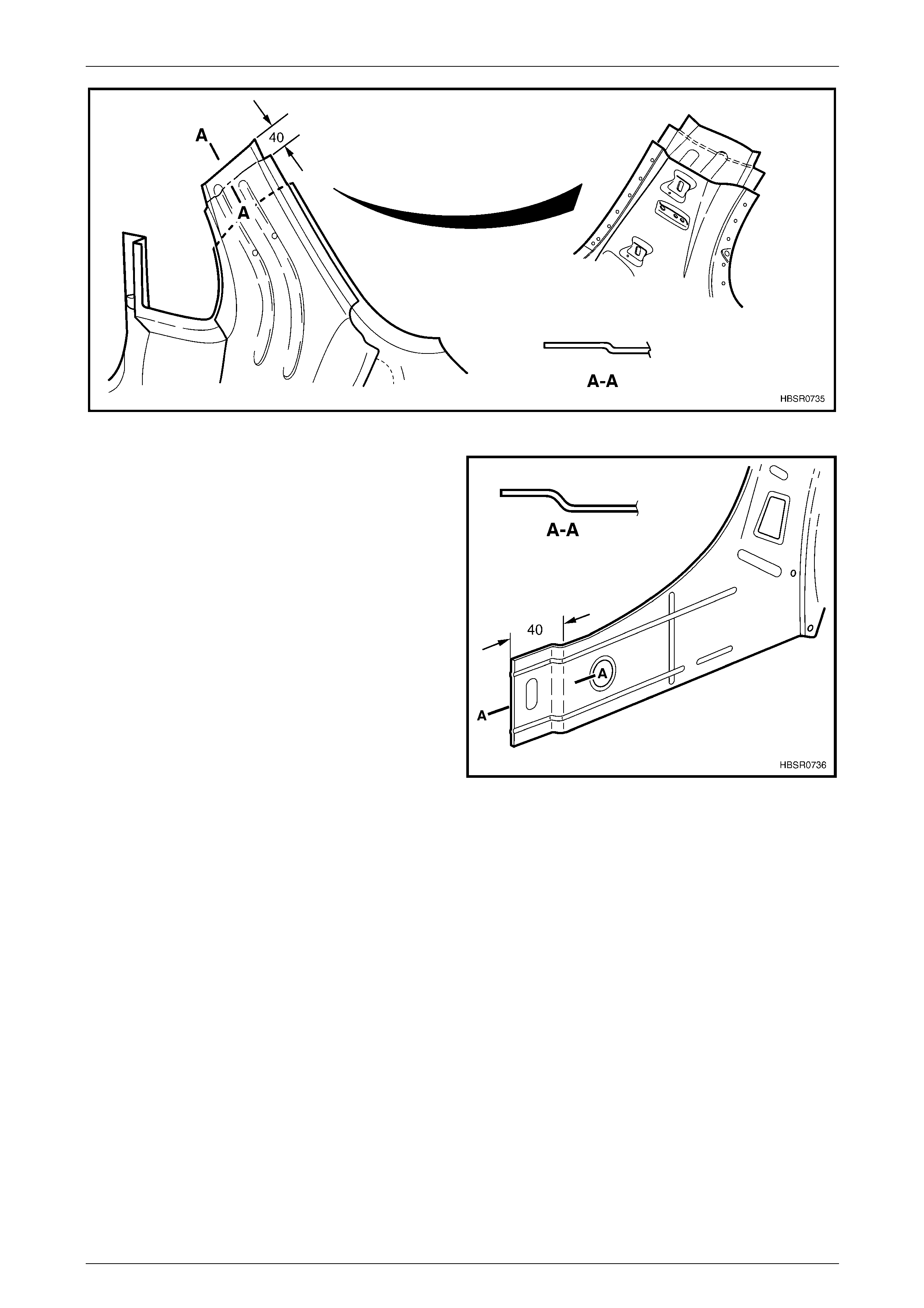
9 Select a cutting point on the hinge pillar. This cut point
should be within the region specified.
Figure 7 – 54
7 Body Side Page 7–26
Page 7–26
10 At the selected point (1), cut through the outer and
reinforcement panels, leavin g the inner panel intact.
11 Mark the inner panel at points 50 mm either side of the
cut line on the outer panel and cut the inner panel at
these two points (2). Spot cut the welds and remove
the 100 mm section of inner panel (3).
Figure 7 – 55
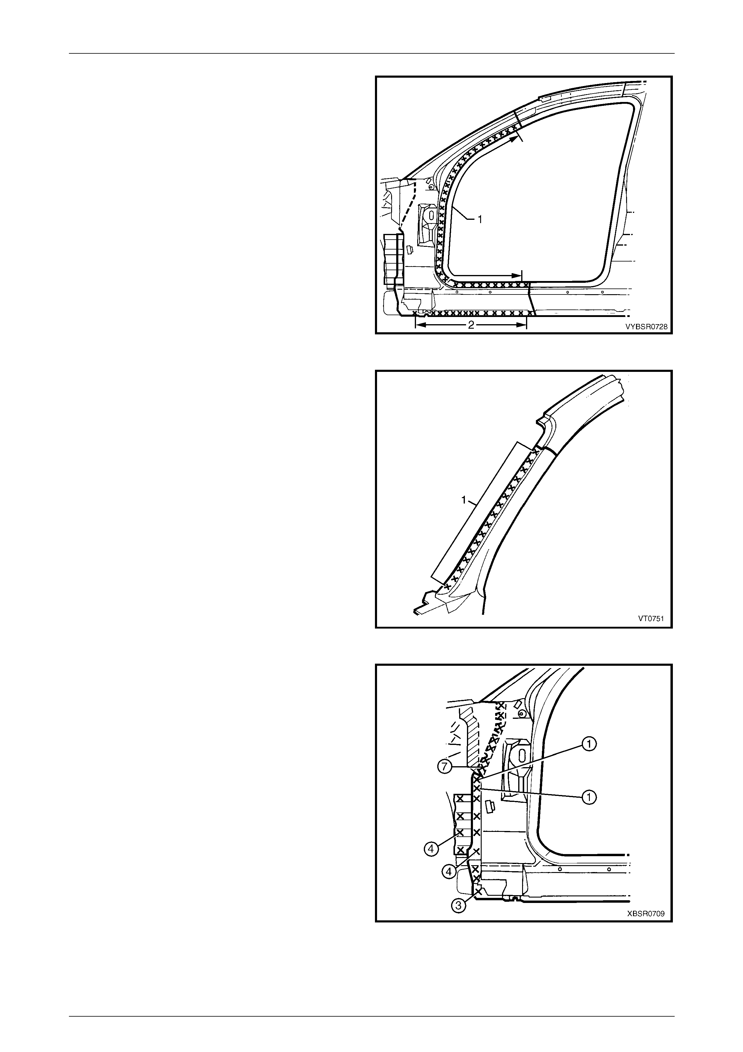
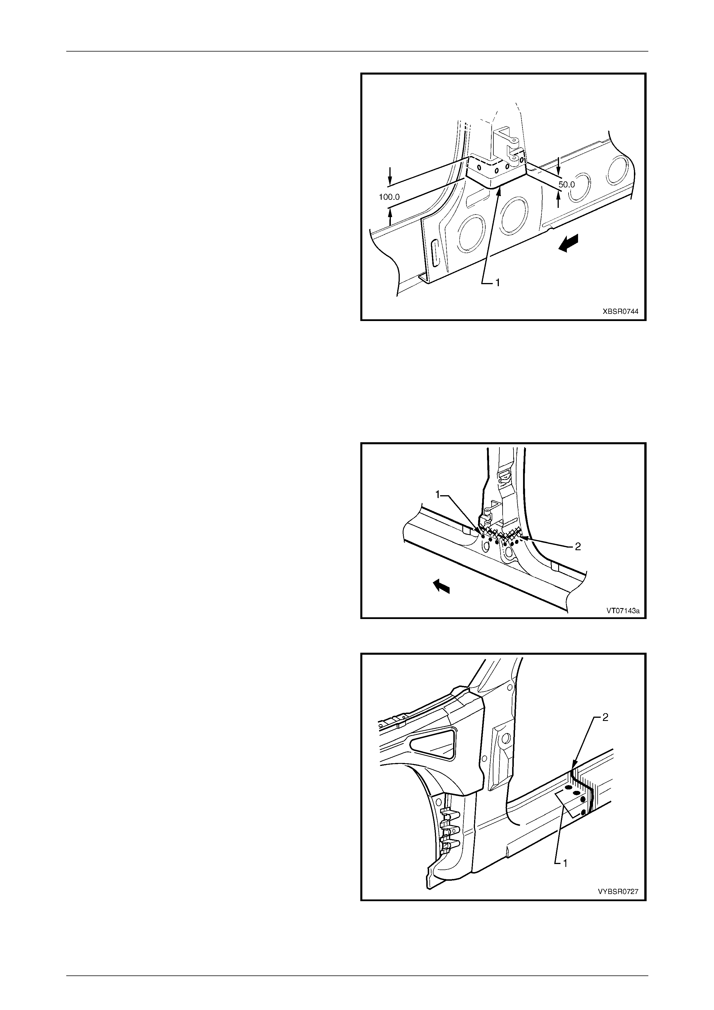
12 Spot cut the welds on the windshield side flange, up to
the point of the cut.
Figure 7 – 56
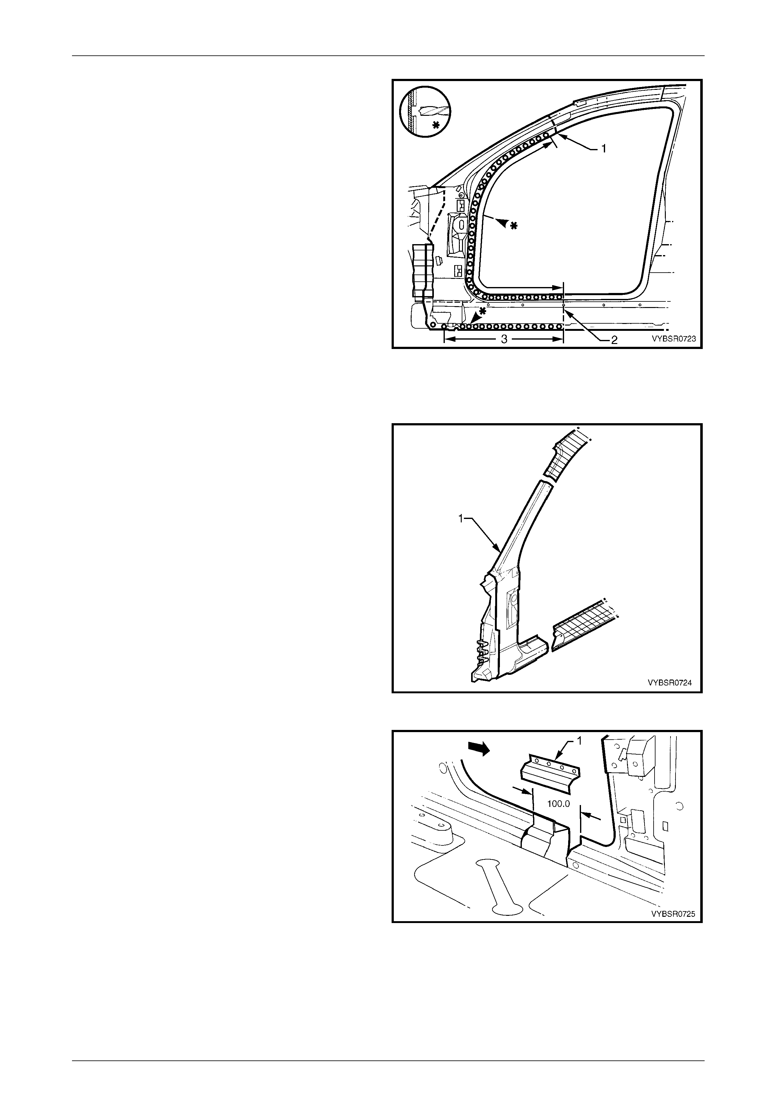
13 Cut through the rocker panel section of the door
opening frame assembly. The cut point (1) sh ould be
through the third rocker panel moulding attaching
hole (2). Cut through both the outer pane l and the
reinforcement.
Figure 7 – 57
7 Body Side Page 7–27
Page 7–27
14 Spot cut the welds on the flange along the front door
opening, from the cut near the top of the hinge
pillar (1) to the cut in the rocker panel (2).
15 Spot cut the welds along the flange (3) below the
rocker panel to the point of the cut.
16 Remove the partial hinge p illar from the vehicle, then
repair any damage to adjacen t parts.
17 Check and rectify the alignment of the body as
required, refer to Section 3 Body Construction.
Figure 7 – 58
Replace
NOTE
Spot welding is the preferred method for
attaching of panels and should be used
whenever possible. Where the spot welding
equipment will not access the required weld
position, a plug weld should b e performed.
NOTE
The same number and p osition of spot welds (or
plug welds) should be used when replacing the
panel, as was used during m anufacture, in order
to maintain the original structural strength of the
vehicle.
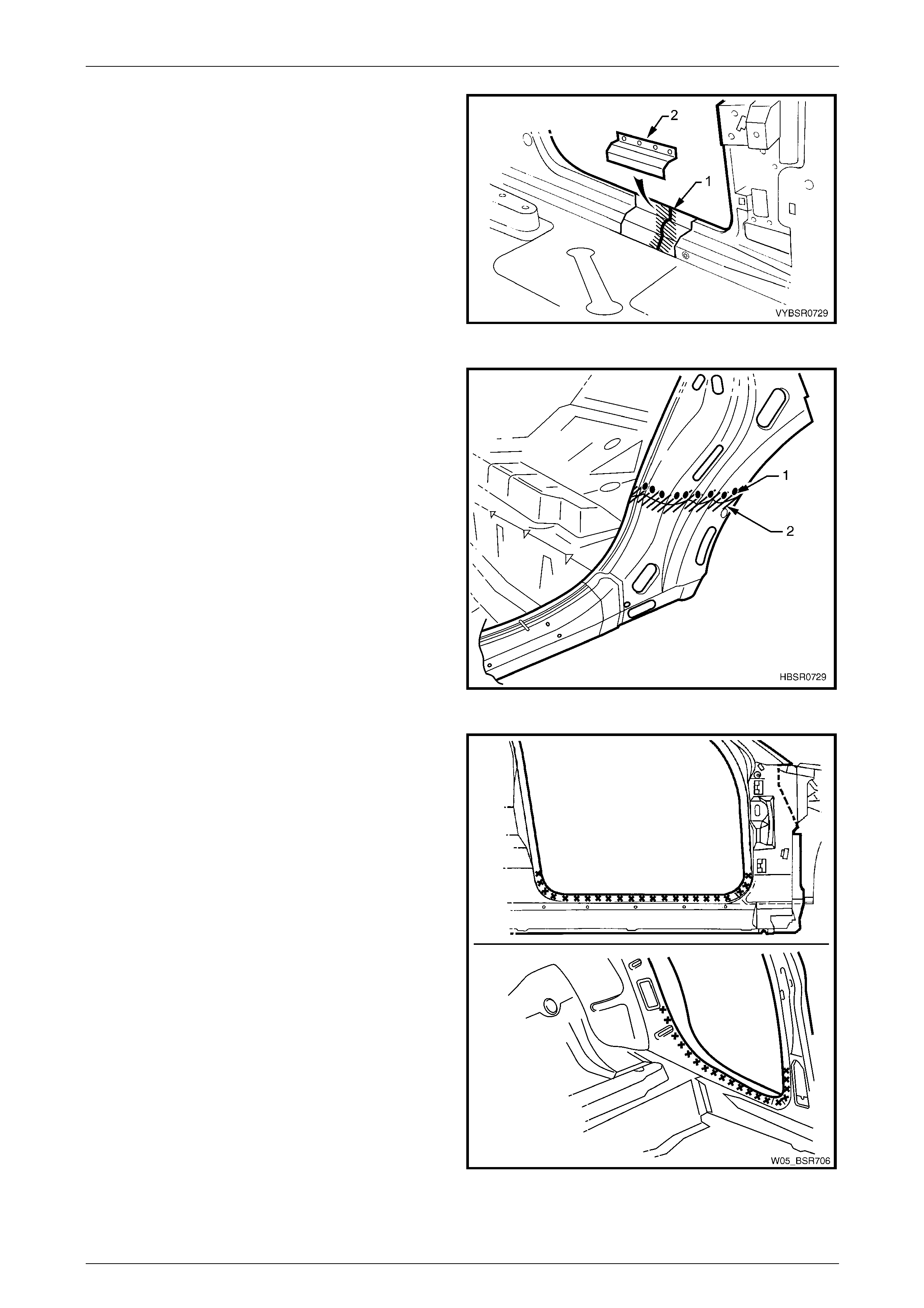
1 Cut a replacement panel section (1), accurately
measuring the position of cuts to match the section
removed.
Figure 7 – 59
2 Remove a section of inner rocker panel (1). Cut
50 mm each side of the cut in the rocker panel. T his
allows access for welding the rocker panel
reinforcement.
Figure 7 – 60
7 Body Side Page 7–28
Page 7–28
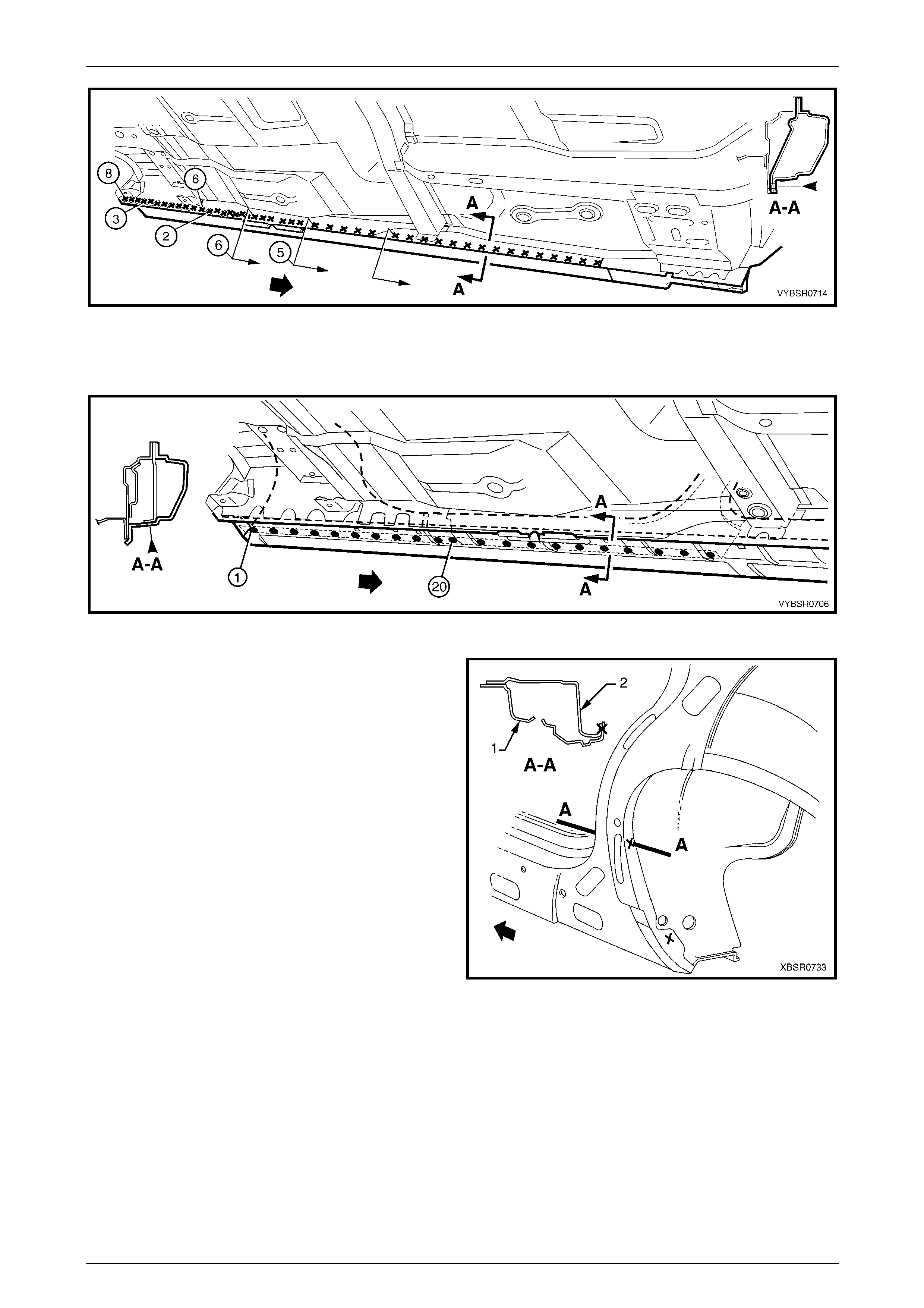
3 Either manufacture a new section or cut an existing
length of surplus rocker panel section, to form a
reinforcement (1), approximately 100 mm in length.
4 Prepare all mating surfaces and treat with Weld
Through Primer (Item 1) as required, refer to
Section 3 Body Construction.
5 Clamp this reinforcement firmly behind the cut section
of rocker panel on the vehicle and spot or plug weld in
place. Position welds at a maximum spacing of 35 mm
apart.
Figure 7 – 61
6 Using a similar technique, ma nufacture or cut a
section of reinforcement panel (1) appro ximat ely
60 mm long, to fit on the inside the outer panel of the
replacement hinge pillar (2) at the point of the cut.
NOTE
Remove the flanges from this reinforcement
panel.
7 Prepare all mating surfaces and treat with Weld
Through Primer (Item 1) as required, refer to
Section 3 Body Construction.
8 Clamp the reinforcement panel firmly behind the outer
panel of the cut section of the hinge pillar and spot
weld (3) in place.
9 Mark the new hinge pillar with drilling locations in
preparation for plug welding where required. Drill holes
as marked.
10 Prepare all mating surfaces and treat with Weld
Through Primer (Item 1) as required, refer to
Section 3 Body Construction.
11 Apply Acrylic Spot Weld Sealer (Item 2), refer to
Section 3 Body Construction.
Figure 7 – 62
12 Clamp the replacement panel (1) in position on the
vehicle and check the door opening dimensions, refer
to Section 3 Body Construction. Adjust position as
required.
Figure 7 – 63
7 Body Side Page 7–29
Page 7–29
13 Plug weld (1) the top of the pillar to the manufactured
reinforcement, then MIG butt weld (2) the two sections
together.
Figure 7 – 64
14 Plug weld (1) the new panel i n the rocker panel region,
then MIG butt weld (2) the two sections together.
Figure 7 – 65
15 Gaining access through the removed sectio n of inner
panel, MIG butt weld (1) the reinforcement panel
together.
16 Butt weld the removed access panel (2) in position.
Replace the spot welds with the same number that
was removed.
Figure 7 – 66
7 Body Side Page 7–30
Page 7–30
17 Spot weld (1) the hinge pillar section along the door
opening flange.
18 Spot weld (2) the flange beneath the rocker pan el,
attaching the new panel to the inner rocker panel.
Figure 7 – 67
19 Spot weld (1) the pillar along the windshield opening
flange.
Figure 7 – 68
20 Spot or plug weld the door openi ng frame assembly to
the inner rocker panel and to the hinge pillar inner
panel assembly. If the sheetmetal was modified to
allow access to these welds, it should be repaired to
its original configuration.
Figure 7 – 69
7 Body Side Page 7–31
Page 7–31
21 Plug weld the inner rocker panel and hinge pillar inner
panel assembly to the rocker panel reinforce m ent.
Figure 7 – 70
22 Gaining access through the section of removed in ner
rocker panel, MIG butt weld (1) the new section of
rocker panel reinforcement to the existing section.
23 Replace the removed section of inner rocker panel (2)
by MIG butt welding it in place and spot welding it
along the door openin g flange. Replace the spot welds
with the same number of as were cut out.
24 Dress the butt welds by grinding or sanding, ensuring
sufficient material remains to guarantee the st rength of
the weld.
25 Install the door hinges, refer to Section 8 Do ors.
26 Refinish and paint panels and other components as
required. Refer to Section 3 Body Construction . Figure 7 – 71
27 Apply Joint Sealer (Item 3) as required. Refer to Section 3 Body Construction.
28 Apply Cavity Wax (Item 8) as required to the inside of any box sections or areas inaccessible to paint,
refer to Section 3 Body Construction.
29 Install the dash panel bolt through the hinge pillar and tighten to the specified torque.
Dash panel retaining b olt
torque specification.................................35.0 – 45.0 Nm
30 Replace the windshield, refer to Section 1A6 Stationary Windows in the MY2005 WL Service Information.
31 Insert Cavity Foam into the hinge pill ar as required, refer to Section 2 Precautions.
32 Install the remaining components as described in the appropriate Section of the MY2005 WL Service Information.
7 Body Side Page 7–32
Page 7–32
2.5 Door Opening Frame Assembly – Partial
Replace, Centre Pillar
NOTE
Cavity Foam is used within the hinge, centre and
body lock pillar cavities. Care is required when
repairing the vehicle in these areas, refer to
Section 2 Precautions prior to beginning any work
for further information.
Remove
1 Remove the adjacent bolt-on panels and components,
refer to the appropriate Section of the MY2005 WL
Service Information.
2 Install the vehicle on a suitab le fixture. As a minimum,
support the appropriate structural sections of the
vehicle on safety stands. Secure a suitable tool
between the front door openi ng flanges to maintain
alignment.
Figure 7 – 72
3 Cut through the door opening frame assemb ly (1) at
the join of the rocker panel reinforcement and centre
pillar reinforcement (2).
NOTE
Make the cut carefully as the rocker panel
reinforcement must not be cut. The centre pillar
reinforcement is removed with the centre pillar
section.
Figure 7 – 73
7 Body Side Page 7–33
Page 7–33
4 Cut through the door opening frame assembly (1)
rearward of the dimple (2) in the flange.
NOTE
Make the cut carefully as the quarter pan el inner
assembly must not be cut.
Figure 7 – 74
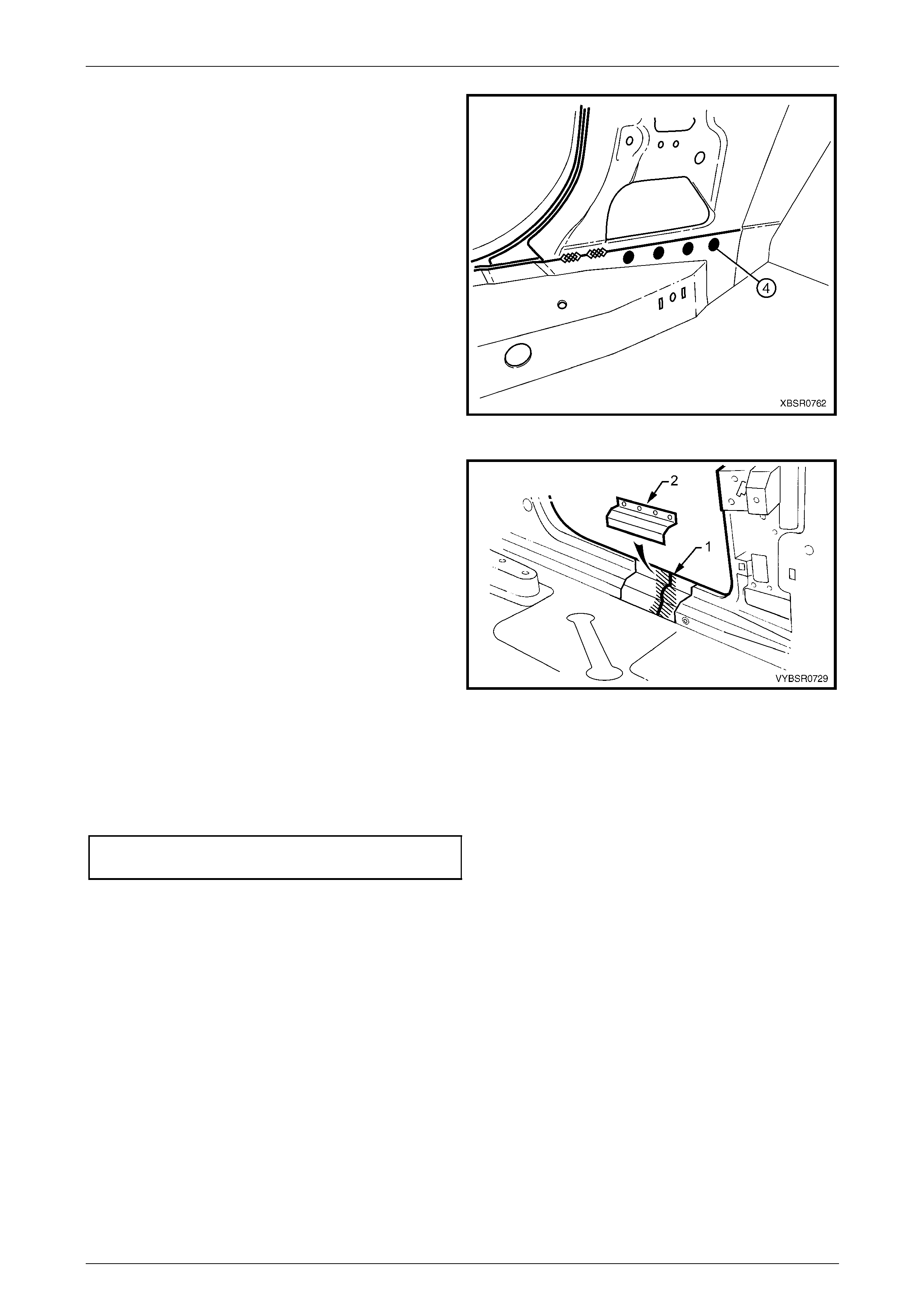
5 Spot cut the welds attaching the underbod y jacking
locator (1) and remove.
6 Spot cut the welds on the flange attaching the centre
pillar section to the inner rocker panel (6). R efer to
weld group A.
7 Spot cut the welds on the underside of the rocker
panel attaching the centre pillar section to the quarter
panel inner assembly (7). Refer to weld group B.
Figure 7 – 75
8 Cut the door opening frame a ssembly (1) and centre
pillar reinforcement (2) at the intersection point of the
centre pillar upper reinforcement (3). The intersection
point can be seen by looking at the side of the flange.
NOTE
Do not cut through the centre pillar inner
reinforcement assembly (4) or quarter panel
inner assembly (5).
Figure 7 – 76
7 Body Side Page 7–34
Page 7–34
9 Spot cut the welds on the door opening flanges on
both sides of the centre pillar and remove the centre
pillar section from the vehicle.
Figure 7 – 77
10 From the remaining section of centre pillar, carefully
remove enough of the outer skin (1) to expose the
spot welds joining the overlapping sections of centre
pillar upper reinforcement (2) and centre pillar
reinforcement (3). NOTE
Do not cut the centre pillar inner reinforcement
assembly (4) and quarter panel inner
assembly (5).
Figure 7 – 78
11 Spot cut as shown, to remove the remaining
tongue (1) of the centre pillar reinforcement. Leave the
holes drilled in reinforcement to facilitate plug welding
the replacement section.
Figure 7 – 79
7 Body Side Page 7–35
Page 7–35
Replace
NOTE
• Spot welding is the preferred method for
attaching of panels and should be used
whenever possible. Where the spot welding
equipment available will not access the
required weld position, a plug weld should be
performed.
• The same number and position of spot welds
(or plug welds) should be used when
replacing the panel, as was used during
manufacture, in order to maintain the original
structural strength of the vehicle.
1 Cut the replacement panel through rocker section as
shown. Accurately measure the position of cuts to
match the removed panel section.
Figure 7 – 80
2 Cut the replacement panel at the top of the centre
pillar (1).
NOTE
Position the cut above the tongue on the centre
pillar reinforcement, which is visible from the
back of the panel.
3 Adjust the cut on the vehicle side of the outer panel so
that it matches the cut on the replacement section.
Figure 7 – 81
7 Body Side Page 7–36
Page 7–36
4 On the replacement panel, cut along each side and
bend back the outer panel (3). This will expose the
spot welds attaching the remaining pi ece of upper
reinforcement (1) to the tongue (2) of the centre pillar
reinforcement.
Figure 7 – 82
5 Spot cut the nine welds and remove the remaining
section of centre pillar upper reinforc ement (1) from
the replacement panel.
Figure 7 – 83
6 Cut two sections from surplus rocker panel piec es, or
manufacture new sections (1), each ap proximately
100 mm in length.
7 Prepare the mating surfaces and treat with Weld
Through Primer (Item 1) as required, refer to
Section 3 Body Construction.
8 Clamp these sections firmly behind both the cut faces
of rocker panel on the vehicle and spot or plug weld in
place. Perform the welds at a maximum spacing of
35 mm.
9 Mark the new panel with drilli ng locations in
preparation for plug welding where required. Drill holes
as marked.
10 Prepare all mating surfaces and treat with Weld
Through Primer (Item 1) as required, refer to
Section 3 Body Construction.
Figure 7 – 84

7 Body Side Page 7–37
Page 7–37
11 Install the replacement panel i n position, sliding the
tongue of the centre pillar reinforcement (1) behind the
centre pillar upper reinforcement (2).
NOTE
Manipulate the rocker panel section in position,
inserting the front first, then the rear.
12 Clamp the assembly in place and p lug weld the centre
pillar upper reinforcement to the centre pill ar
reinforcement at the upper join.
13 Plug weld the rocker panel section to the
reinforcement sections.
14 Spot weld along the door opening flanges on both
sides of the centre pillar.
Figure 7 – 85
15 Fold the outer panel back in position at the top of the
centre pillar. Spot weld along the door flange section
and MIG butt weld the sections together as shown.
16 MIG butt weld the joins in the rocker panel.
Figure 7 – 86
7 Body Side Page 7–38
Page 7–38
17 Plug weld the flange attaching the centre pil lar
section (1) to the inner rocker panel (2). Refer to
weld group A.
18 Plug weld on the underside of the rocker panel the
centre pillar section to the quarter panel inn er
assembly (3). Refer to weld group B.
19 Plug weld the underbody jacking locator (4) in place.
20 Install the door hinges, refer to Section 8 Do ors.
21 Dress the welds by grinding or sanding, ensuring
sufficient material remains to guarantee the st rength of
the weld. Finish the area using an appropriate
technique.
22 Refinish and paint panels and other components as
required. Refer to Section 3 Body Construction .
23 Apply Joint Sealer (Item 3) as required. Refer to
Section 3 Body Construction.
24 Apply Cavity Wax (Item 8) as required to the inside of
any box sections or areas inaccessible to paint, refer
to Section 3 Body Construction.
25 Insert Cavity Foam into the centre pillar as r equired,
refer to Section 2 Precautions.
26 Install the remaining components as described in the
appropriate Section of the MY2005 WL Service
Information.
Figure 7 – 87
7 Body Side Page 7–39
Page 7–39
2.6 Door Opening Frame Assembly – Partial
Replace, Body Lock Pillar
Remove
1 Remove the adjacent bolt on pane ls and components
as described in the appropriate Section of the MY2005
WL Service Information.
2 Install the vehicle on a suitab le fixture. As a minimum,
support the appropriate structural sections of the
vehicle on safety stands.
3 Remove the rear side glass and rear windscreen, refer
to Section 1A6 Stationary Win dows in the MY2005 WL
Service Information.
4 Remove rear quarter panel, refer to
2.1 Rear Quarter Panel – Replace.
Figure 7 – 88
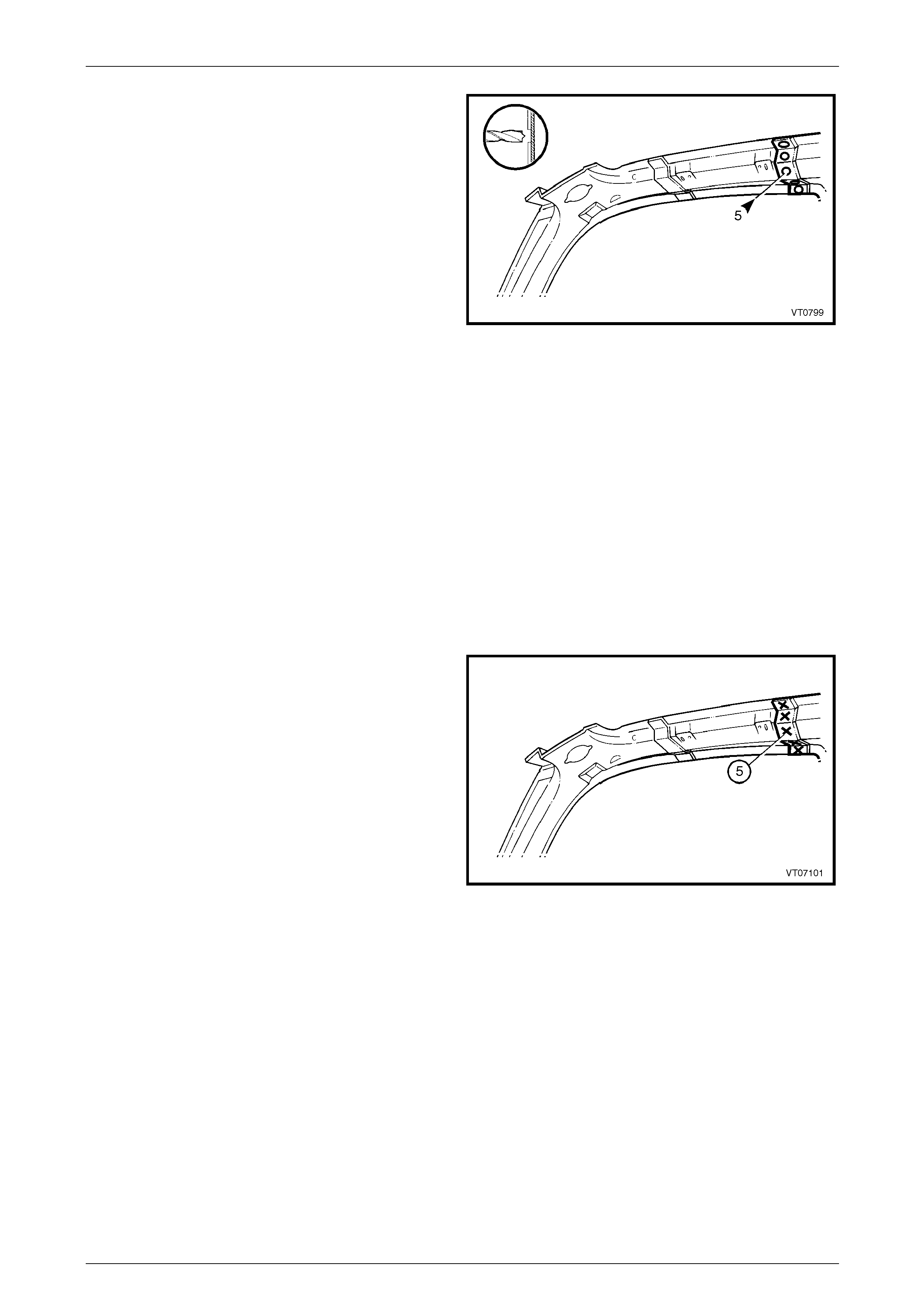
5 Select a cut line (1) within the region of the body lock
pillar as shown.
6 Carefully cut through the outer panel only.
NOTE
This area is below the back body pillar
reinforcement and will be covered by the qu arter
panel when replaced.
Figure 7 – 89
7 Body Side Page 7–40
Page 7–40
7 Select a cutting position on the rocker panel section of
the door opening frame within the region as shown.
The cut region is between the two dimples.
8 Cut through the outer skin only.
NOTE
There is no reinforcement panel in this area of
the vehicle.
9 Spot cut the welds attaching the door opening frame to
the quarter panel inner assembl y and inner rocker
panel assembly as shown.
NOTE
The number of spots will vary depending on the
cut point through the rocker panel section.
10 Remove any remaining sp ot welds as required.
11 Remove the partial body lock pillar panel from the
vehicle, then repair any damage to adjace nt parts.
12 Check and repair, if necessary, the alignm ent of the
body shell. Refer to the dimensions available in
Section 3 Body Construction.
Figure 7 – 90
Replace
NOTE
• Spot welding is the preferred method for
attaching of panels and should be used
whenever possible. Where the spot welding
equipment available will not access the
required weld position, a plug weld should be
performed.
• The same number and position of spot welds
(or plug welds) should be used when
replacing the panel, as was used during
manufacture, in order to maintain the original
structural strength of the vehicle.
1 Cut a new replacement body lock pill ar panel section, accurately measuring the position of cuts to match the
removed section.
7 Body Side Page 7–41
Page 7–41
2 Manufacture or cut a section of reinforcement
panel (1) (approximately 100 mm long) to fit on the
inside of the existing rocker panel at the point of the
cut.
NOTE
Any new sections fabricated to be used as
reinforcements, must be manufactured from
steel sheet of a minimum thickness of 1.6 mm.
3 Prepare all mating surfaces and treat with Weld
Through Primer (Item 1) as required. Refer to
Section 3 Body Construction.
4 Clamp the manufactured reinforcement panel firmly to
the inside of the rocker panel on the ve hicle and plug
weld in position. Position welds at a maximum spacing
of 35 mm.
5 Mark the new body lock pillar panel with drilling
locations, in preparation for p lug welding. Drill holes as
required.
Figure 7 – 91
6 Prepare all mating surfaces and treat with Weld Through Primer (Item 1) as required.
Refer to Section 3 Body Construction.
7 Clamp the new body lock pill ar section in place on the vehic le and check door opening di mensions.
Refer to dimensions in Section 3 Body Construction.
8 MIG weld the join at the body lock pillar.
Figure 7 – 92
7 Body Side Page 7–42
Page 7–42
9 Plug weld the replacement panel to the ma nufactured
reinforcement section in the rocker panel area and
plug or spot weld along the quarter pan el inner
assembly and inner rocker panel assembly.
10 MIG weld the join at the rocker panel.
11 Replace rear quarter panel, refer to
2.1 Rear Quarter Panel – Replace.
12 Apply Joint Sealer (Item 3) as required.
Refer to Section 3 Body Construction.
13 Refinish and paint panels and other components as
required. Refer to Section 3 Body Construction .
14 Apply Cavity Wax (Item 8) as required to the inside of
any box sections or areas i na ccessible to paint.
Refer to Section 3 Body Construction.
15 Reinstall the remaining components as described in
the appropriate Section of the MY2005 WL Service
Information.
Figure 7 – 93
7 Body Side Page 7–43
Page 7–43
2.7 Door Opening Frame Assembly – Partial
Replace, Rocker Panel
This procedure details the replacement of the
rocker panel section of the door opening
frame assembly.
As there are several critical reinforcements in
the lower hinge pillar area, the rocker panel
section must not be cut forward of the area
shown. If the rocker panel is damaged
forward of this area, replace the rocker panel
and partial hinge pillar as one sectio n. Modify
this procedure accordingly, also refer to
2.4 Door Opening Frame Assembly – Partial
Replace, Hinge Pillar.
Remove
1 Remove the adjacent bolt-on panels and components
as described in the appropriate Section of the MY2005
WL Service Information.
2 Remove the rear quarter panel, refer to
2.1 Rear Quarter Panel – Replace.
3 Secure the vehicle on a suitable fixture. As a
minimum, support the appropriate structural s ections
of the vehicle on safety stands. Install suitable bracing
in the vehicle to ensure that the correct body
alignment is maintained when the rocker panel section
is removed.
Figure 7 – 94
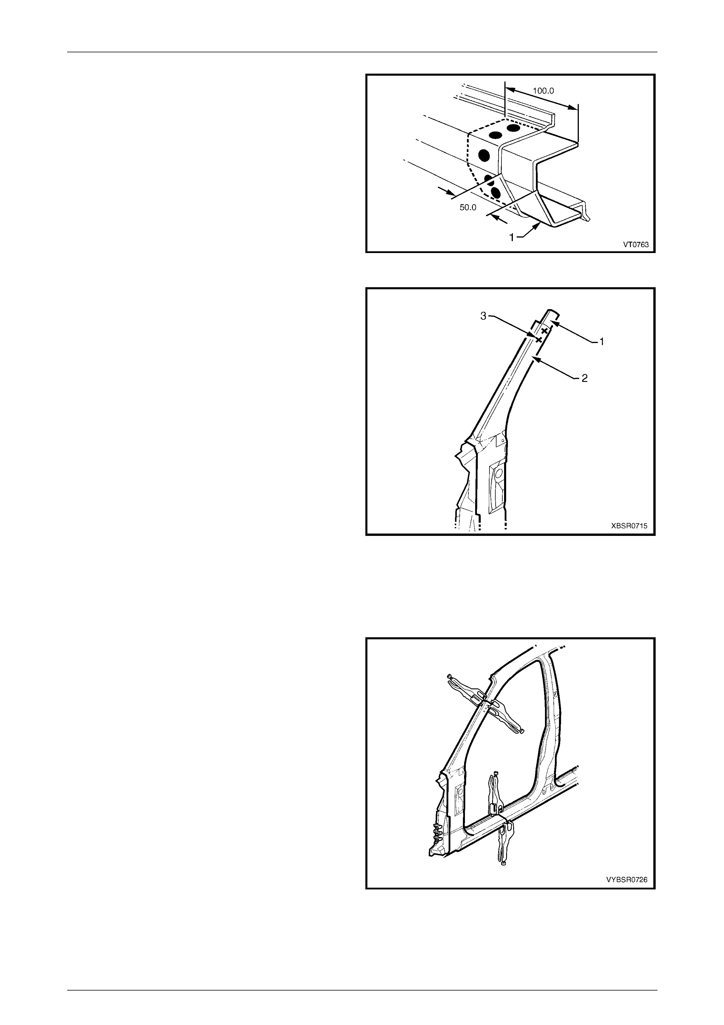
4 Cut through the rocker panel section of the door
opening frame assembly. The cut point (1) m ust not be
further forward than the third rocker panel m oulding
attaching hole (2). Cut through both the outer panel
and the reinforcement.
Figure 7 – 95
7 Body Side Page 7–44
Page 7–44
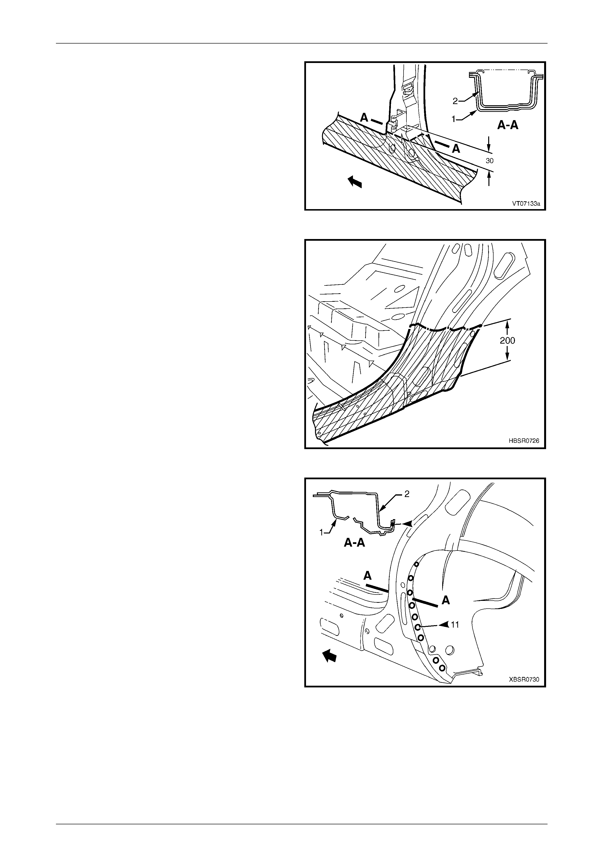
5 Using a suitable cutting tool, cut through the centre
pillar at a position 30 mm below the lower edge of the
door hinge. Cut through both the door opening frame
assembly (1) and centre pillar reinforcement (2).
Figure 7 – 96
6 Cut through the body lock pillar at a point approx.
200 mm above the top of the rocker panel.
NOTE
There is no reinforcement panel in this area of
the vehicle.
Figure 7 – 97
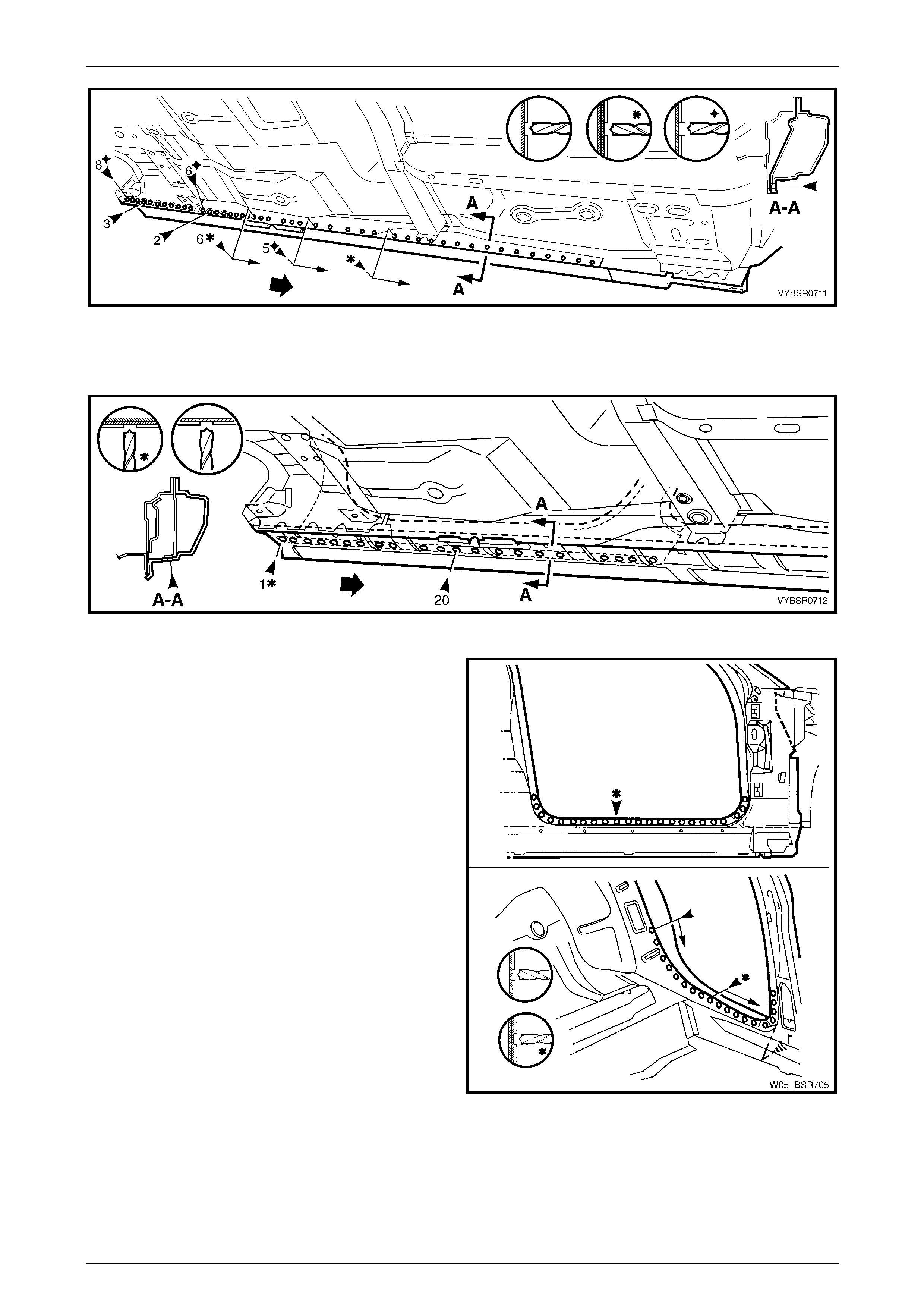
7 Depending on the cut location, spot cut any welds
remaining around the wheelhouse as required (most
would have been removed with the rear quarter
panel), attaching the door openi ng frame
assembly (2).
8 Spot cut along the vertical flange below the rocker
panel as required, to separate the rocker panel section
from the inner rocker panel and quarter p anel inner
assembly. Refer to Figure 7 – 99.
NOTE
Depending on the cut line position, many of
these welds may have been previously removed
if the rear quarter panel has been remove d.
Figure 7 – 98
7 Body Side Page 7–45
Page 7–45
Figure 7 – 99
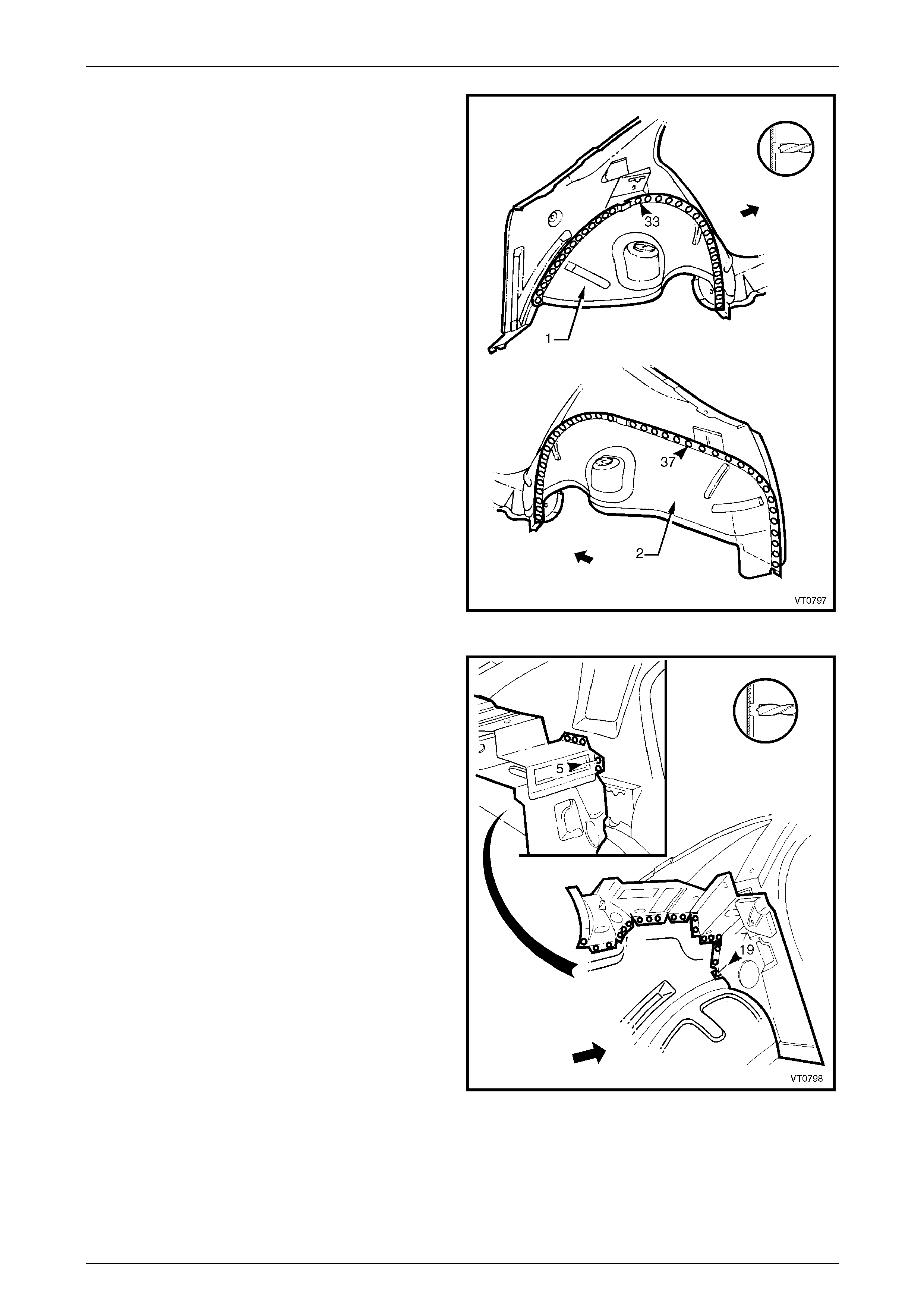
9 Spot cut the welds attaching the rocker panel section to the quarter p an el inner assembly as required.
Refer to Figure 7 – 100.
Figure 7 – 100
10 Spot cut the welds along the lower edge of the front
and rear door openings as required to complete the
detachment of the rocker panel section.
11 Remove the panel from the vehicle, then repair an y
damage to adjacent parts.
12 Check and rectify the alignment of the body as
required, refer to Section 3 Body Construction.
Figure 7 – 101
7 Body Side Page 7–46
Page 7–46
Replace
NOTE
Spot welding is the preferred method for
attaching of panels and should b e used whenever
possible. Where the spot welding equipment will
not access the required weld position, a plug
weld should be performed.
NOTE
The same number and position of spot welds (or
plug welds) should be used when replacing the
panel, as was used during manufacture, in order
to maintain the original structural strength of the
vehicle.
1 Cut a new replacement rocker panel section.
Accurately measure the position of the cuts on the
removed section.
2 Remove a section of inner rocker panel (1), cut 50 mm
each side of the cut in the rocker panel. This allows
access for welding the rocker panel reinf orcement.
Figure 7 – 102
3 Manufacture or cut a reinforcement (1) (appr oximately
100 mm long) to fit on the inside of the existing rocker
panel at the point of the cut.
4 Prepare the mating surfaces and treat with Weld
Through Primer (Item 1) as required, refer to
Section 3 Body Construction.
5 Clamp the manufactured reinforcement firmly to the
inside of the rocker panel section of the d oor opening
frame assembly on the vehicle and plug weld in
position. Position welds at a maximum spacing of
35 mm.
Figure 7 – 103
7 Body Side Page 7–47
Page 7–47
6 Manufacture or cut a reinforcement (1) (appr oximately
100 mm long) to fit inside of the existing centre pillar
section at the point of the cut.
7 Prepare the mating surfaces and treat with Weld
Through Primer (Item 1) as required, refer to
Section 3 Body Construction.
8 Clamp the manufactured reinforcement panel firmly to
the inside of the outer panel of the door opening frame
assembly on the vehicle and plug weld in position.
Position welds at a maximum spacing of 35 mm.
9 Repeat steps 6, 7 and 8 and install a reinforcement at
the rear rocker panel / body lock pillar lower cut as
required.
10 Mark the replacement rocker panel section with drilling
positions in preparation for pl ug welding as required.
NOTE
The outer panel will be plug welded from the
outer side of the vehicle, while the rocker panel
and centre pillar reinforcements will be butt
welded from the inner side of the vehicle.
11 Prepare all mating surfaces and treat with Weld
Through Primer (Item 1) as required, refer to
Section 3 Body Construction.
Figure 7 – 104
12 Install the replacement section onto the vehicle by
sliding the front and centre pillar sections o nto the
reinforcements, while lifting the rear into posi tion.
13 Clamp the panel in position.
14 Weld the new section to the centre pillar by plug
welding (1).
15 MIG butt weld the centre pillar reinforcement from
inside the centre pillar, through the large ho le in the
inner panel immediately behind the weld.
16 Finish the centre pillar attachment by MIG welding (2)
along the join of the outer panel.
Figure 7 – 105
17 Plug weld (1) the replacement section at the front join,
then MIG butt weld (2) the two sections together.
Figure 7 – 106
7 Body Side Page 7–48
Page 7–48
18 Gaining access through the section of removed in ner
rocker panel assembly, MIG butt weld (1) the new
section of rocker panel reinforcement to the existin g
section.
19 Replace the removed section of inner rocker panel
assembly (2) by MIG butt welding it in place and spot
welding it along the door ope ning flange. Replace the
spot welds with the same number as were removed.
Figure 7 – 107
20 Plug weld the rear join as required (1).
21 MIG butt weld the joint line between the panels (2).
Figure 7 – 108
22 Spot or plug weld the flanges of the front and rear door
openings as required.
NOTE
Use the same number and position of welds as
removed during removal.
23 Spot or plug weld the door opening frame al ong the
flange below the rocker panel as requ ired, refer to
Figure 7 – 110.
Figure 7 – 109
7 Body Side Page 7–49
Page 7–49
Figure 7 – 110
24 Plug weld up through the rocker panel to attach the replac ement section to the quarter panel inner assembl y.
Refer to Figure 7 – 111.
Figure 7 – 111
25 If required, spot weld the replacement section to the
quarter panel inner assembly around the rear wheel
arch at several places to retain the new section in
position.
NOTE
Fully spot weld this flange when the r ear quarter
panel is installed, welding through all three
panels.
Refer to 2.1 Rear Quarter Panel – Replace.
26 Refinish and paint panels and other components as
required. Refer to Section 3 Body Construction .
27 Apply Joint Sealer (Item 3) as required.
Refer to Section 3 Body Construction.
28 Apply Cavity Wax (Item 8) as required to the inside of
any box sections or areas i na ccessible to paint,
refer to Section 3 Body Construction.
29 Install the remaining components as described in the
appropriate Section of the MY2005 WL Service
Information.
Figure 7 – 112
7 Body Side Page 7–50
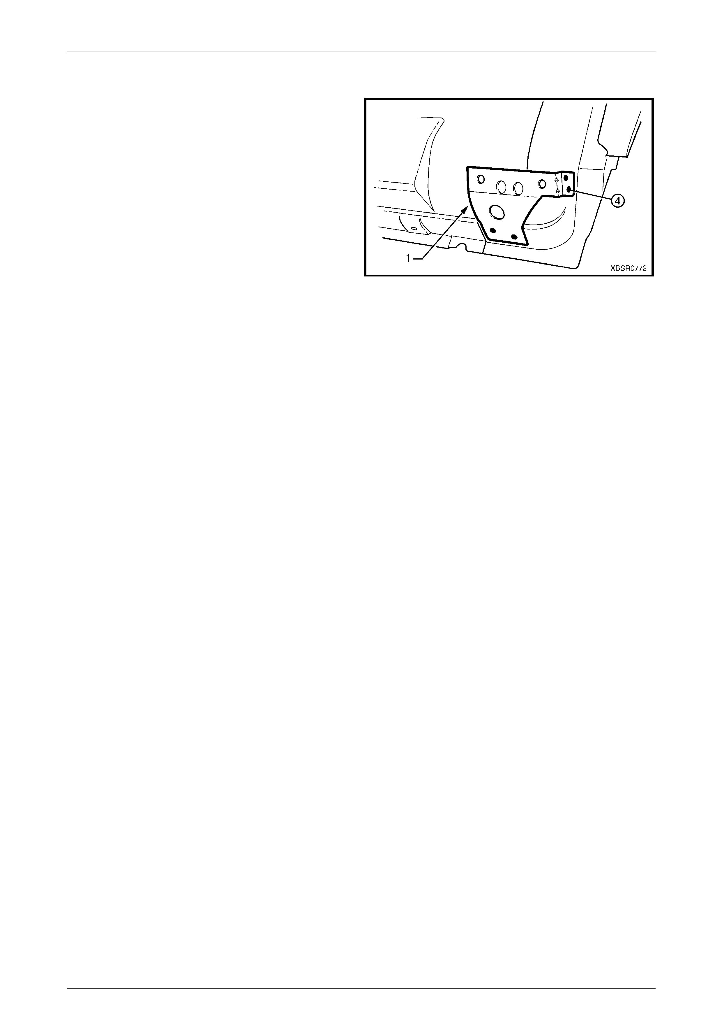
Page 7–50
2.8 Fender Lower Rear Bracket – Replace
1 The fender lower rear bracket (1) is spot welded at
four places to the door opening frame assembly.
2 Clamp the fender lower rear bracket positi on as shown
prior to plug welding and check the alignment of the
fender to the body and front door.
3 Refinish and paint panels and other components as
required. Refer to Section 3 Body Construction .
4 Apply Cavity Wax (Item 8) as required to the inside of
any box sections or areas i na ccessible to paint,
refer to Section 3 Body Construction.
Figure 7 – 113
7 Body Side Page 7–51
Page 7–51
2.9 Hinge Pillar Inner Panel Assembly –
Replace
Remove
1 Remove the adjacent bolt-on panels and components
as described in the appropriate Section of the MY2005
WL Service Information.
2 Remove the door opening frame assemb ly, refer to
2.3 Door Opening Frame Assembly – Replace, or
remove the hinge pillar section of the door opening
frame assembly, refer to 2.4 Door Opening Frame
Assembly – Partial Replace, Hinge Pil lar .
3 If required, remove the dash panel assembl y, refer to
Section 5 Cockpit Module.
NOTE
If the cockpit module is not damaged an
alternative is provided in this pr ocedure.
4 Add bracing as required to maintain the alignment of
the vehicle structure.
Figure 7 – 114
5 Grind the MIG welds (1) attaching the hinge pill ar inner
panel assembly to the inner rocker panel.
Figure 7 – 115
6 Spot cut the welds attaching the hinge pillar i nner
panel assembly to the roof front header and quarter
panel inner extension.
NOTE
Structural adhesive is applied to join (1). If the
roof panel has not been removed, it will be very
difficult to remove the panel. As an alternative:
• If only the lower section is damaged, detach
the hinge pillar inner u pper panel (1) from the
hinge pillar inner lower panel (2) and replace
the lower panel, or
• Cut the hinge pillar inner panel assembly (3)
approximately 50 mm from the top of
the windscreen aperture. If a partial
replacement of the door opening frame
assembly is being performed, this point is
50 mm above the cut in the outer panels (4).
Refer to Figure 7 – 117.
Figure 7 – 116
7 Body Side Page 7–52
Page 7–52
Figure 7 – 117
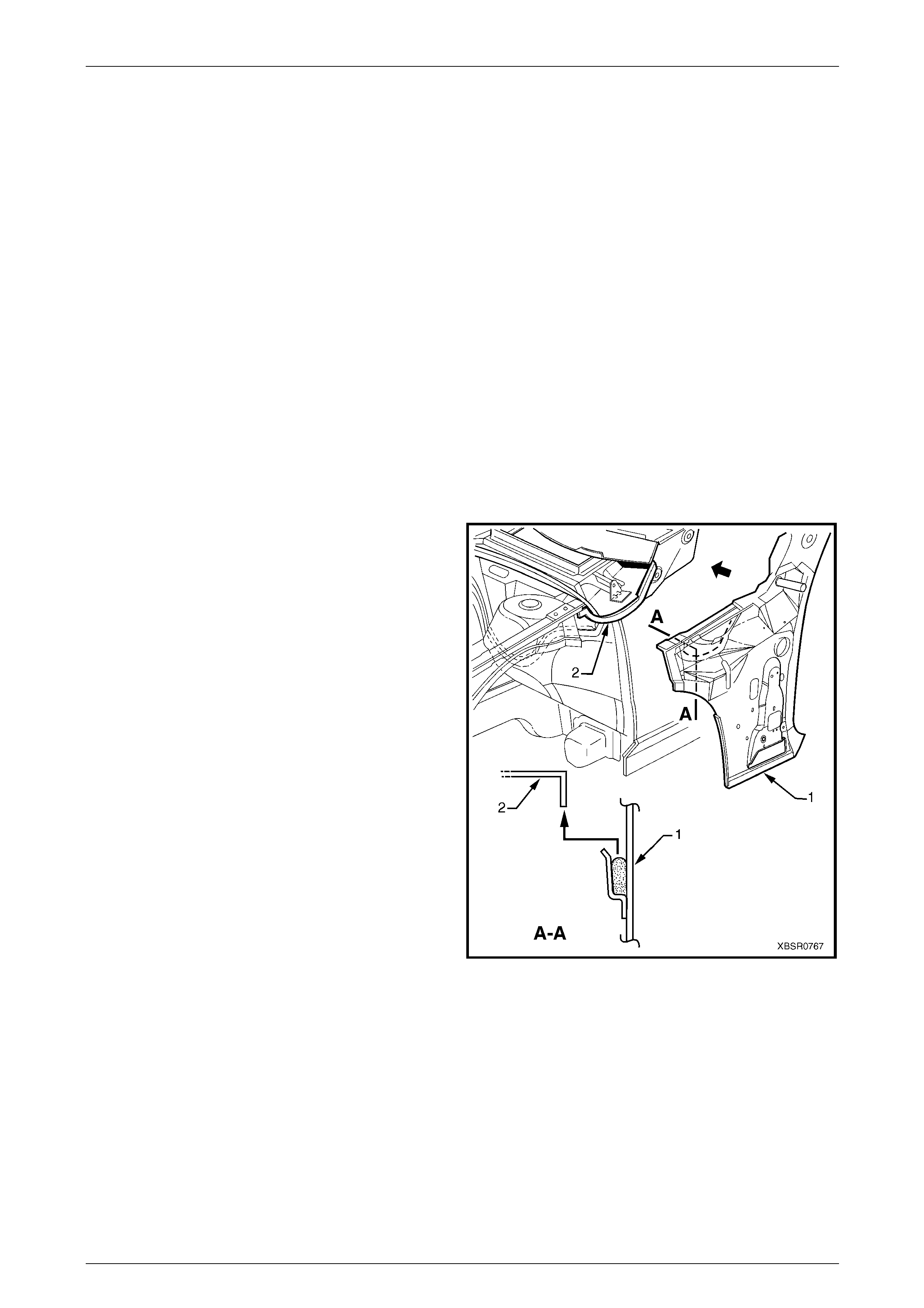
7 Spot cut the welds attaching the hinge pillar i nner
panel assembly to the front wheelho use p anel and
front floor panel extension, refer to weld group A.
8 If the dash panel assembly was not removed, spot cut
the eight welds attaching the adhesive channels to the
hinge pillar inner panel assembly, refer to weld
group B.
9 If required, remove any remainin g spot welds where
the wheelhouse panel u pper side rail attached the
front wheelhouse panel and hinge pillar inner panel
assembly.
10 Cut the adhesive between the dash panel assembly
and hinge pillar inner panel assembly.
11 Remove the hinge pillar in ner panel assembly from the
vehicle and as required, cle an off any remaining
adhesive and ensure the adhesive channels are
removed.
12 Repair any damage to adjacent parts as required. Figure 7 – 118
Replace
NOTE
• Spot welding is the preferred method for
attaching of panels and should be used
whenever possible. Where the spot welding
equipment will not access the required weld
position, a plug weld should b e performed.
• The same number and position of spot welds
(or plug welds) should be used when
replacing the panel, as was used during
manufacture, in order to maintain the original
structural strength of the vehicle.
7 Body Side Page 7–53
Page 7–53
1 If an alternate removal method was used, referring to Figure 7 – 117, either:
2 Cut the replacement section to match the cut at the top of the hinge pill ar, or
3 Spot cut the welds attaching the hinge pillar inner upper panel to the hinge pillar inner lower panel.
4 Mark the new panel and drill holes in preparation for plug welding where required.
5 Prepare all mating surfaces and treat with Weld Through Primer (Item 1) as required,
refer to Section 3 Body Construction.
6 If the dash panel assembly was removed, it will be installed later, proceed to Step 7.
7 If the dash panel assembly was NOT removed, prepare the adhesive channels on the replacement section and the
dash panel assembly, refer to Section 5 Cockpit Module .
8 Mix the dash panel silicone adhesive refer to Section 5 Cockpit Module. Apply the adh esive to fill the adhesive
channels on the replacement section.
NOTE
Only the correct material described in
Section 5 Cockpit Module is to be used.
9 If the full hinge pillar inner panel assembly is being replaced, apply structural adhesive (Item 6) to the mating
surfaces of the hinge pillar inner panel as sembly and quarter panel inner extension,
refer to Section 3 Body Construction.
10 Install and clamp the new panel i n position on the
vehicle.
NOTE
If the dash panel assembly was not removed,
place the hinge pillar inner panel assembly (1)
slightly lower and slide it upwards ensuring the
dash panel flange (2) seats into the adhesive
channel.
11 Temporarily install the dash panel attaching bolts
through the hinge pillar i nner panel assembly and
within the plenum chamber.
12 Finish the application of the dash panel adhesive,
refer to Section 5 Cockpit Module.
Figure 7 – 119
7 Body Side Page 7–54
Page 7–54
13 If the full hinge pillar inner panel assembly was
removed, spot or plug weld the hinge pill ar inner panel
assembly to the roof front header and quarter panel
inner extension.
NOTE
Ensure the structural adhesive (Item 6) is
applied to the join (1) refer to
Section 3 Body Construction.
14 If only the lower section was removed, spot or plug
weld the hinge pillar inner upper panel (1) to the hinge
pillar inner lower panel (2), refer to Figure 7 – 121.
15 If the pillar was cut near the top of the windscreen
aperture, either MIG butt weld the join (3) if the full
door opening frame assembly was remov ed, or make
two tack welds to secure it until the door opening
frame assembly hinge pillar section is installed, also
refer to Figure 7 – 121.
NOTE
This join forms the top access cut point for
joining of the reinforcement as described in
2.4 Door Opening Frame Assembly – Partial
Replace, Hinge Pillar .
Figure 7 – 120
Figure 7 – 121

7 Body Side Page 7–55
Page 7–55
16 Spot or plug weld the hinge pillar in ner panel assembly
to the front wheelhouse panel and front floor
extension.
Figure 7 – 122
17 MIG weld two places (1) across the inner rocker panel
and hinge pillar inner panel assembly.
18 Replace the door opening fram e assembly, refer to
2.3 Door Opening Frame Assembly – Replace or the
hinge pillar sec t ion of the door opening frame
assembly, refer to 2.4 Door Opening Frame Assembly
– Partial Replace, Hinge Pill ar.
19 Refinish and paint panels and other components as
required. Refer to Section 3 Body Construction .
20 Apply Joint Sealer (Item 3) as required.
Refer to Section 3 Body Construction.
21 Apply Cavity Wax (Item 8) as required to the inside of
any box sections or areas inaccessible to paint, refer
to Section 3 Body Construction.
22 Install the remaining components as described in the
appropriate Section of the MY2005 WL Service
Information.
Figure 7 – 123
7 Body Side Page 7–56
Page 7–56
2.10 Quarter Panel Inner Assembly – Replace
Remove
1 Remove the adjacent bolt on panels and components as described in the appro priat e Section of the MY2005 WL
Service Information.
2 Mount the vehicle on a suitable jig to mai ntain correct
body alignment when the quarter panel inner
assembly is removed.
3 Remove the rear side glass and rear windscreen as
described in Section 1A6 Stationary Windows in the
MY2005 WL Service Information.
4 Remove rear quarter panel refer to
2.1 Rear Quarter Panel – Replace.
5 Remove the roof panel and roof support p anel,
refer to Section 9 Roof.
6 Remove the door opening frame, refer to
2.3 Door Opening Frame Assembly – Replace.
7 Add further bracing tools as required to maintain the
alignment of the vehicle structure.
Figure 7 – 124
8 Cut the spot welds and grind off the MIG welds (1),
attaching the quarter panel inner assembly to the inner
rocker panel assembly.
Figure 7 – 125
7 Body Side Page 7–57
Page 7–57
9 Spot cut the welds attaching the quarter panel inner
assembly to the wheelhouse inner, Left-hand (1) or
wheelhouse inner, Right-hand (2).
Figure 7 – 126
10 Spot cut the welds attaching the quarter panel inner
assembly to the rear wheelhouse brace assembly.
Figure 7 – 127
7 Body Side Page 7–58
Page 7–58
11 Spot cut the five welds attaching the quarter panel
inner assembly to the side front roof frame.
12 Remove the panel from the vehicle, then repair an y
damage to adjacent parts.
13 Check and repair, if necessary, the alignm ent of the
body shell. Refer to the dimensions available in
Section 3 Body Construction.
Figure 7 – 128
Replace
NOTE
• Spot welding is the preferred method for
attaching of panels and should be used
whenever possible. Where the spot welding
equipment available to the repairer will not
access the required weld pos it ion, a plu g weld
should be performed.
• The same number and position of spot welds
(or plug welds) should be used when
replacing the panel, as was used during
manufacture, in order to maintain the original
structural strength of the vehicle.
1 Mark the new panel with drilling locations, in
preparation for plug welding where required. Drill holes
as marked.
2 Prepare all mating surfaces and treat with Weld
Through Primer (Item 1) as required. Refer to
Section 3 Body Construction.
3 Position the new panel on the vehicle and clamp in
place. Confirm position of pan el by referring to
Section 3 Body Construction. Reposition the panel if
required.
4 Spot weld the quarter panel inner ass embly to the side
front roof frame.
Figure 7 – 129
7 Body Side Page 7–59
Page 7–59
5 Spot weld the quarter panel inner assembly to the
wheelhouse inner, Left-hand (1) or wheelhouse inner,
Right-hand (2).
Figure 7 – 130
6 Spot weld the quarter panel inner assembly to the rear
wheelhouse br ace assembly.
Figure 7 – 131

7 Body Side Page 7–60
Page 7–60
7 Spot weld and MIG weld in four places (1), the quarter
panel inner assembly to the inner rocker pan el
assembly.
8 Replace the door opening fram e, refer to
2.3 Door Opening Frame Assembly – Replace.
9 Replace the roof and roof support panels, as
described in Section 9 Roof Pane l.
10 Replace rear quarter pane l as described in
Section 10 Body Rear.
11 Apply Joint Sealer (Item 3) as required.
Refer to Section 3 Body Construction.
12 Refinish and paint panels and other components as
required, refer to Section 3 Body Construction. Figure 7 – 132
13 Apply Cavity Wax (Item 8) as required to the inside of any box sections or areas inaccessible to paint,
refer to Section 3 Body Construction.
14 Replace rear side glass and rear windscreen, refer to Section 1A6 Stationary Windows in the MY2005 WL Service
Information.
15 Replace the adjacent bolt on panels and components as describe d in the appropriate Section of the MY2005 WL
Service Information.
7 Body Side Page 7–61
Page 7–61
2.11 Quarter Panel Inner Assembly – Partial
Replace
Remove
1 Remove the adjacent bolt-on panels and components
as described in the appropriate Section of the MY2005
WL Service Information.
2 If required, mount the vehicle on a suitable fixture.
Secure a suitable tool bet ween the rear door opening
flanges to maintain alignment once the sections are
removed.
3 Remove the rear side glass and rear windscreen as
described in Section 1A6 Stationary Windows in the
MY2005 WL Service Information.
4 Remove the rear quarter panel, refer to
2.1 Rear Quarter Panel – Replace.
5 Remove body lock pillar secti on of the door opening
frame assembly, refer to 2.6 Door Opening Frame
Assembly – Partial Replace, Body Lock Pillar.
Figure 7 – 133
8 Carefully cut through the quarter panel inner assembly
at the rocker panel region.
NOTE
The position of the cut (1) should be a minimum
of 50 mm shorter than that of the outer panel (2)
to allow sufficient access for rejoining.
Figure 7 – 134
9 Grind off the MIG welds (1) and cut enough spot
welds (2) to detach the quarter panel inner assembly
from the inner rocker panel.
Figure 7 – 135
7 Body Side Page 7–62
Page 7–62
10 Spot cut the welds attaching the quarter panel inner
assembly to the wheelhouse inner, Left-hand (1) or
wheelhouse inner, Right-hand (2).
Figure 7 – 136
11 Spot cut the welds attaching the quarter panel inner
assembly to the rear wheelhouse brace assembly.
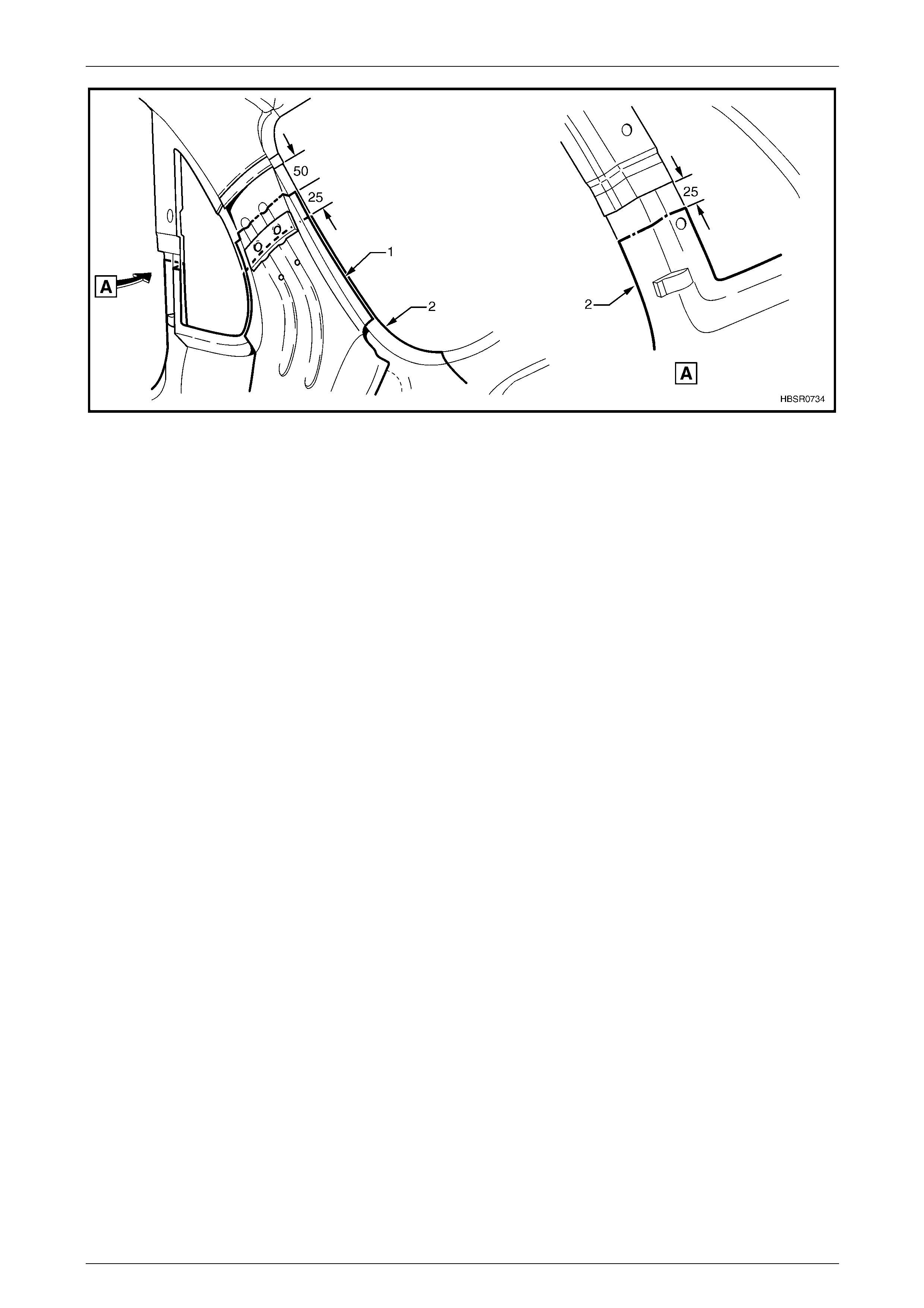
12 Cut through the back body pillar reinforcement
panel (1) at a point 50 mm below the quarter panel
braze joint reinforcement. Cut through th e quarter
panel inner assembly (2) at a point at least 2 5 mm
below the back body pillar reinforcement cut and for
the body lock pillar, 25 mm below the door opening
frame cut, refer Figure 7 – 138.
NOTE
Remove any cavity foam from adjacent
areas prior to working in this area.
Refer to Section 2 Precautions.
Figure 7 – 137
7 Body Side Page 7–63
Page 7–63
Figure 7 – 138
13 Remove the partial quarter panel inner assembly from the vehicle, then repair any damage to adjace nt parts.
14 Check and repair, if necessary, the alignment of the body shell. Refer to the dimensions availabl e in
Section 3 Body Construction.
Replace
NOTE
• Spot welding is the preferred method for
attaching of panels and should be used
whenever possible. Where the spot welding
equipment will not access the required weld
position, a plug weld should b e performed.
• The same number and position of spot welds
(or plug welds) should be used when
replacing the panel, as was used during
manufacture, in order to maintain the original
structural strength of the vehicle.
1 Accurately cut a replacement body l ock pillar section from a new panel ass embly. The new panel should be cut
40 mm longer at the mating faces to allo w for overlap.
2 Form a joggle (1) at the top end of the reinforcement pa nel to facilitate a lap joint. The inner pan el will be butt
welded. Refer to Figure 7 – 139.
NOTE
Accurately measure the required length of joggle
to match the overlap. This should be slightly in
excess of 40 mm.
7 Body Side Page 7–64
Page 7–64
Figure 7 – 139
3 Form another joggle in the rocker panel area of the
new panel to allow for a lap joint in this area.
NOTE
Accurately measure the requ ired length of joggle
to match the overlap. This should be slightly in
excess of 40 mm.
4 Mark the new panel and the existing panels with
drilling locations in prep aration for plug welding where
required. Drill holes as marked.
5 Prepare all mating surfaces and treat with Weld
Through Primer (Item 1) as required.
Refer to Section 3 Body Construction.
6 Position the new panel on the vehicle and clamp in
place. Confirm position of pan el by referring to
Section 3 Body Construction. Reposition the panel if
required. Figure 7 – 140
7 Plug weld the lap joints at the top of the back bod y pillar reinforcement. Figure 7 – 141.
8 Finish the joints by MIG welding the quarter panel inner assembly butt joint and back bod y pillar reinforcement the
lap joint.
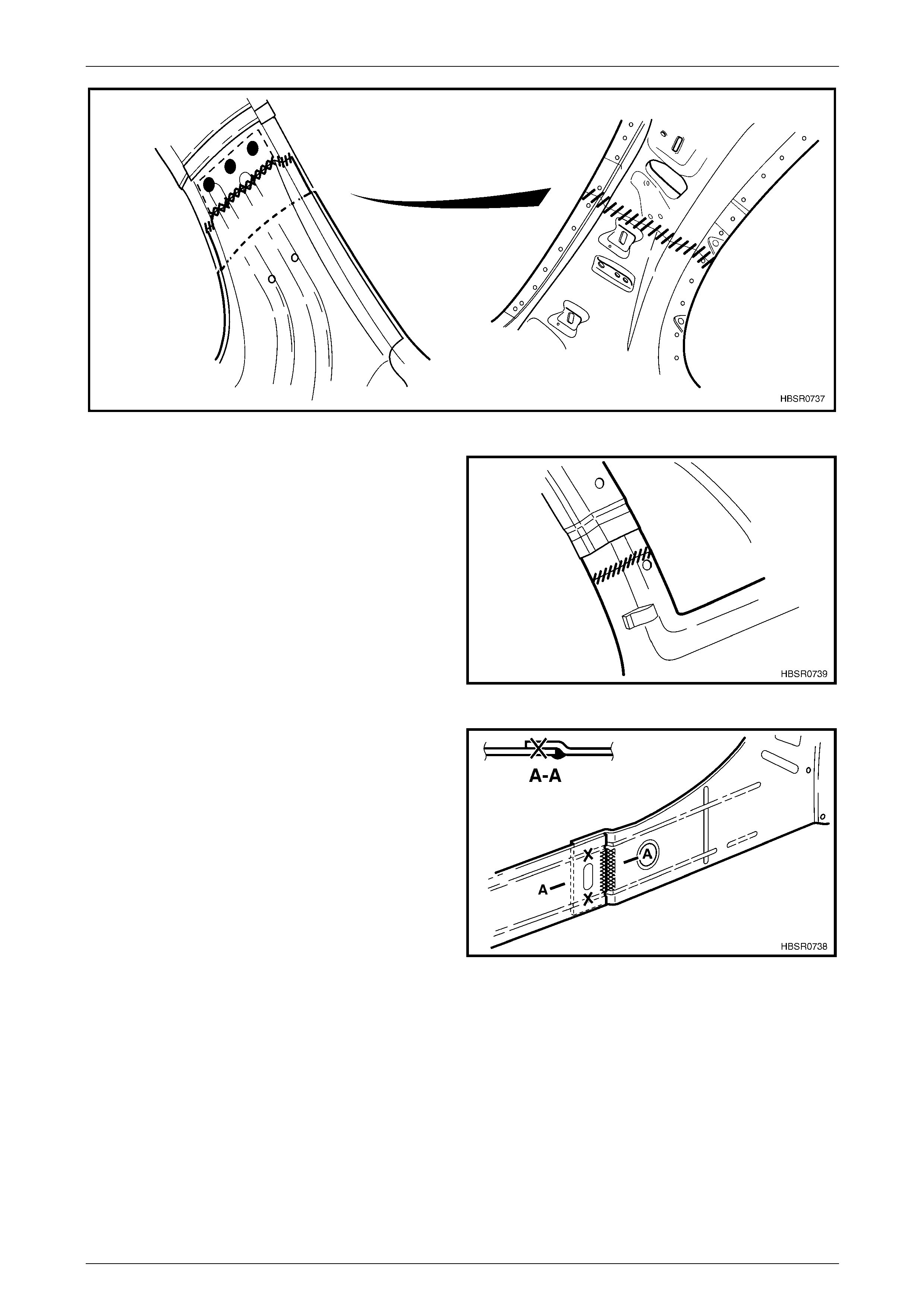
7 Body Side Page 7–65
Page 7–65
Figure 7 – 141
9 MIG weld the butt joint at the body lock pillar.
Figure 7 – 142
10 Plug weld the lap joints at the rocker panel j oint.
11 Finish the joint by MIG welding the inner lap joint.
Figure 7 – 143
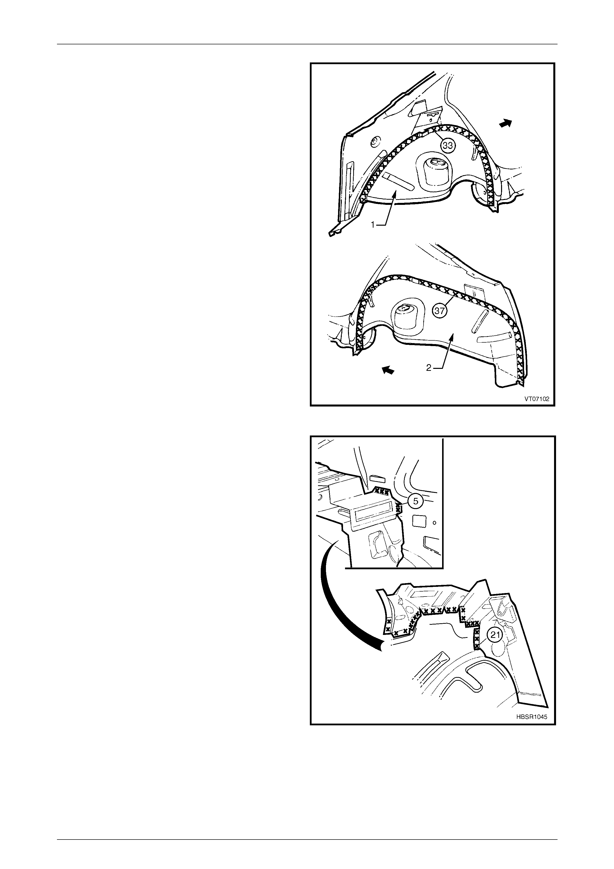
7 Body Side Page 7–66
Page 7–66
12 Spot weld the quarter panel inner assembly to the
wheelhouse inner, Left-hand (1) or wheelhouse inner,
Right-hand (2).
Figure 7 – 144
13 Spot welds the quarter panel inner assembly to the
rear wheelhouse brace assembly.
Figure 7 – 145
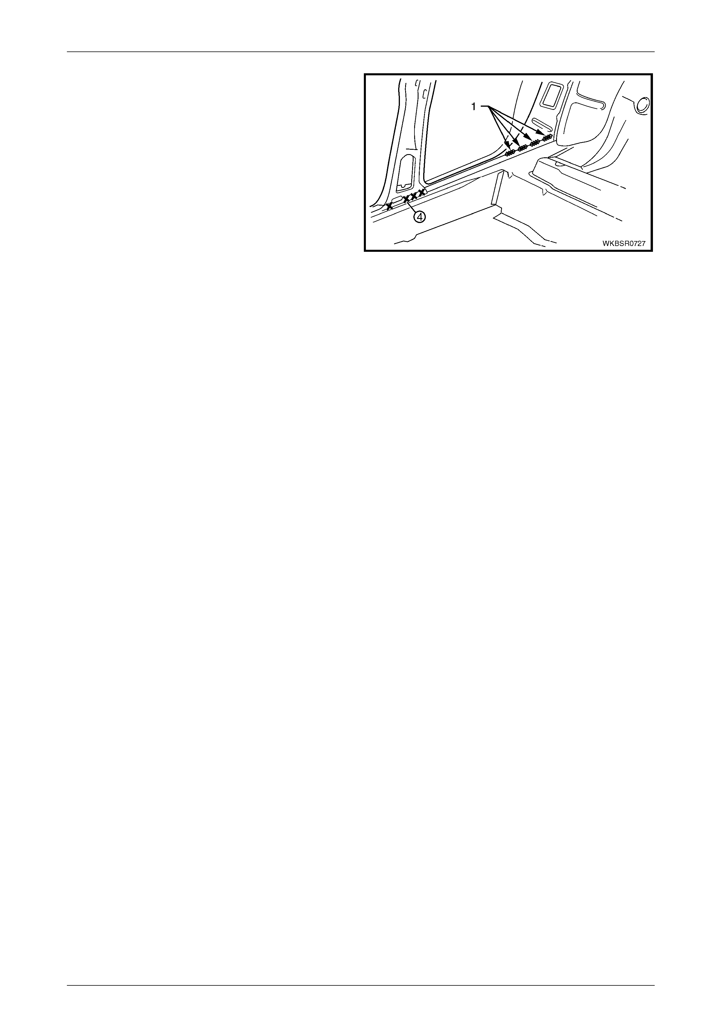
7 Body Side Page 7–67
Page 7–67
14 MIG weld (1) in four places (each 25 mm long) to
attach the quarter panel inner assembly to the inner
rocker panel assembly.
15 Replace partial bod y lock pillar. Refer to the operation
earlier in this Section.
16 Replace the rear quarter panel as described in
Section 10 Body Rear.
17 Apply Joint Sealer (Item 3) as required.
Refer to Section 3 Body Construction.
18 Refinish and paint panels and other components as
required. Refer to Section 3 Body Construction .
19 Apply Cavity Wax (Item 8) as required to the inside of
any box sections or areas i na ccessible to paint.
Refer to Section 3 Body Construction.
20 Replace the rear side glass and rear windscreen as
described in Section 1A6 Stationary Windows in the
MY2005 WL Service Information.
21 Replace the adjacent bolt on p anels and components
as described in the appropriate Section of the MY2005
WL Service Information.
Figure 7 – 146