
8 Doors Page 8-1
Page 8-1
Section 8
Doors
ATTENTION
Before performing any service operation or other procedure described in this Section, refer to Section 2
Precautions in this Supplement and Section 00 Warnings, Cautions and Notes in the MY2005 WL Service
Information for correct workshop practices with regard to safety and/or property damage.
The structure of the body shell has been
developed using complex design and
development techniques. In addition to
meeting all required standards, the vehicle
body is also a critical part of the overall safety
systems. It is therefore imperative the repair
procedures described here are adhered to
during all vehicle body repairs.
1 General Description ...............................................................................................................................2
1.1 Doors, Liftgate and Endgate Components .......................................................................................................... 2
Front Door .............................................................................................................................................................. 3
Rear Door ............................................................................................................................................................... 3
2 Service Operations.................................................................................................................................4
2.1 Front Door Assembly – Replace........................................................................................................................... 4
Remove................................................................................................................................................................... 4
Reinstall.................................................................................................................................................................. 5
Adjust...................................................................................................................................................................... 6
2.2 Rear Door Assembly – Replace............................................................................................................................ 7
Remove................................................................................................................................................................... 7
Reinstall.................................................................................................................................................................. 8
Adjust...................................................................................................................................................................... 8
2.3 Door Hinge (Body Side) – Replace....................................................................................................................... 9
Remove................................................................................................................................................................... 9
Reinstall.................................................................................................................................................................. 9
2.4 Front Door Outer Panel – Replace...................................................................................................................... 10
Remove................................................................................................................................................................. 10
Replace................................................................................................................................................................. 11
2.5 Rear Door Outer Panel – Replace....................................................................................................................... 13
Remove................................................................................................................................................................. 13
Replace................................................................................................................................................................. 14
3 Torque Wrench Specifications............................................................................................................16
4 Special Tools ........................................................................................................................................17

8 Doors Page 8-2
Page 8-2
1 General Description
This Section describes the repair and replacement procedures for the door s.
The procedures are limited to the replacement the door assembly or the outer panel, which is attached to the inner panel
assembly by way of a folded hem flange and structural adhesiv e. Removal of bolt-on trim and hardware components is
not covered in this Supplement. Reference must be made to the appropriate Sections in the MY2005 WL Service
Information.
The front and rear door assemblies are supplied with the door hinge flaps that are MIG welded to the d oor opening frame
assembly.
The door impact beams must not be heated,
welded or straightened in any way, due to
their critical role in driver/passenger safety.
Damage to the impact beams will necessitate
the replacement of the entire door assembly.
NOTE
It is imperative that the correct body adhesives,
sealers, deadeners and cavity waxes are used
when repairing the body structure. Refer to
Section 3 Body Construction for details of the
correct materials and their commercially available
equivalents.
1.1 Doors, Liftgate and Endgate
Components
The components and assemblies shown in Figure 8 – 1 and Figure 8 – 2 are the serviceable parts that form the basis of
the repair procedures in this Section. For a detailed view of the body components, refer to Section 3 Body Construction .
NOTE
Always refer to an Authorised Retailer for spare
parts availability configurations.
8 Doors Page 8-3
Page 8-3
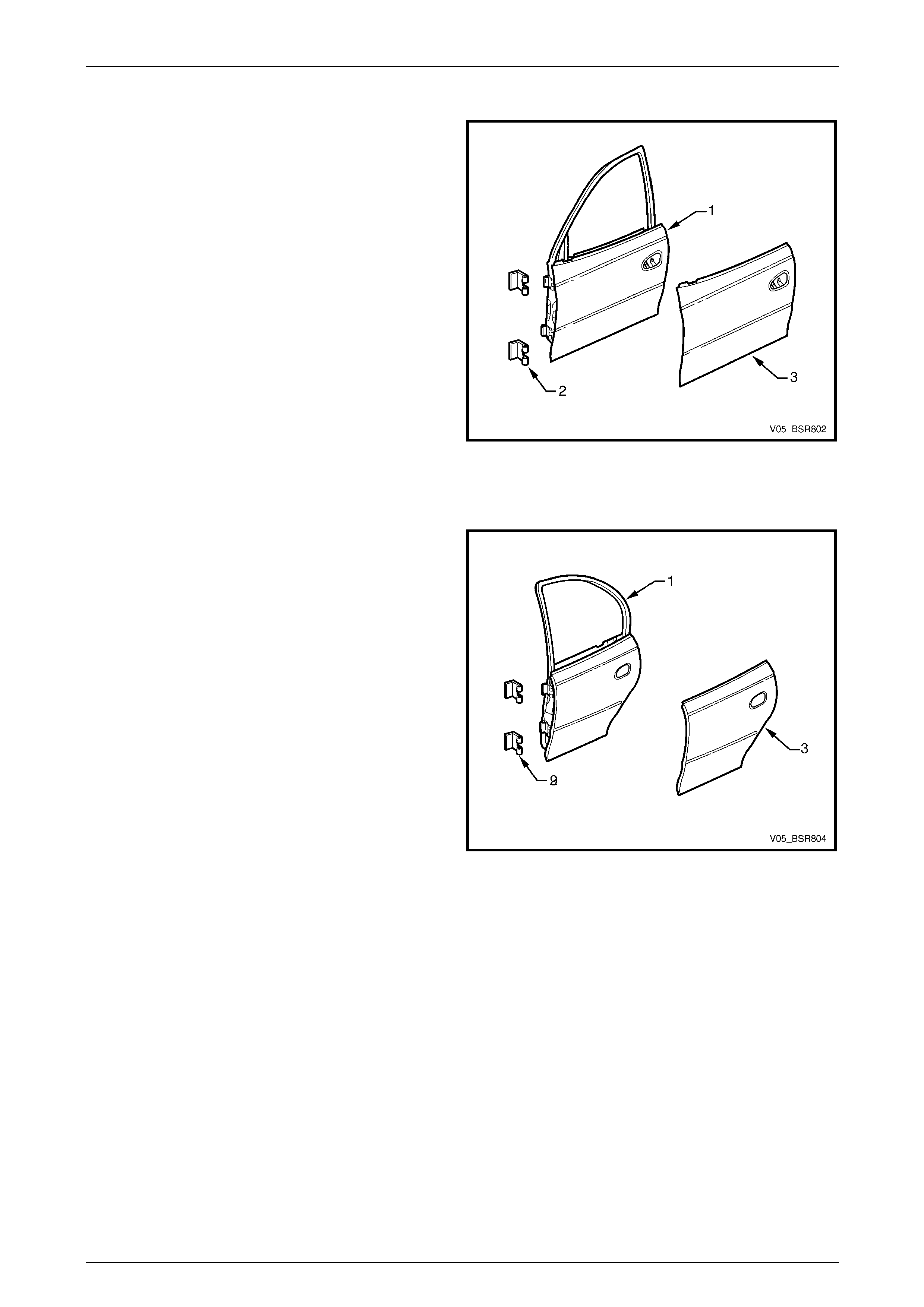
Front Door
Legend
1 Front Door Assembly
2 Front Door Hinge (Body Side)
3 Front Door Outer Panel
Figure 8 – 1
Rear Door
Legend
1 Rear Door Assembly
2 Rear Door Hinge (Body Side)
3 Rear Door Outer Panel
Figure 8 – 2
8 Doors Page 8-4
Page 8-4
2 Service Operations
2.1 Front Door Assembly – Replace
Remove
NOTE
Disassemble the door trim and hardware as
required. Refer to Section 1A5 Front And Rear
Door Assemblies in the MY2005 WL Service
Information.
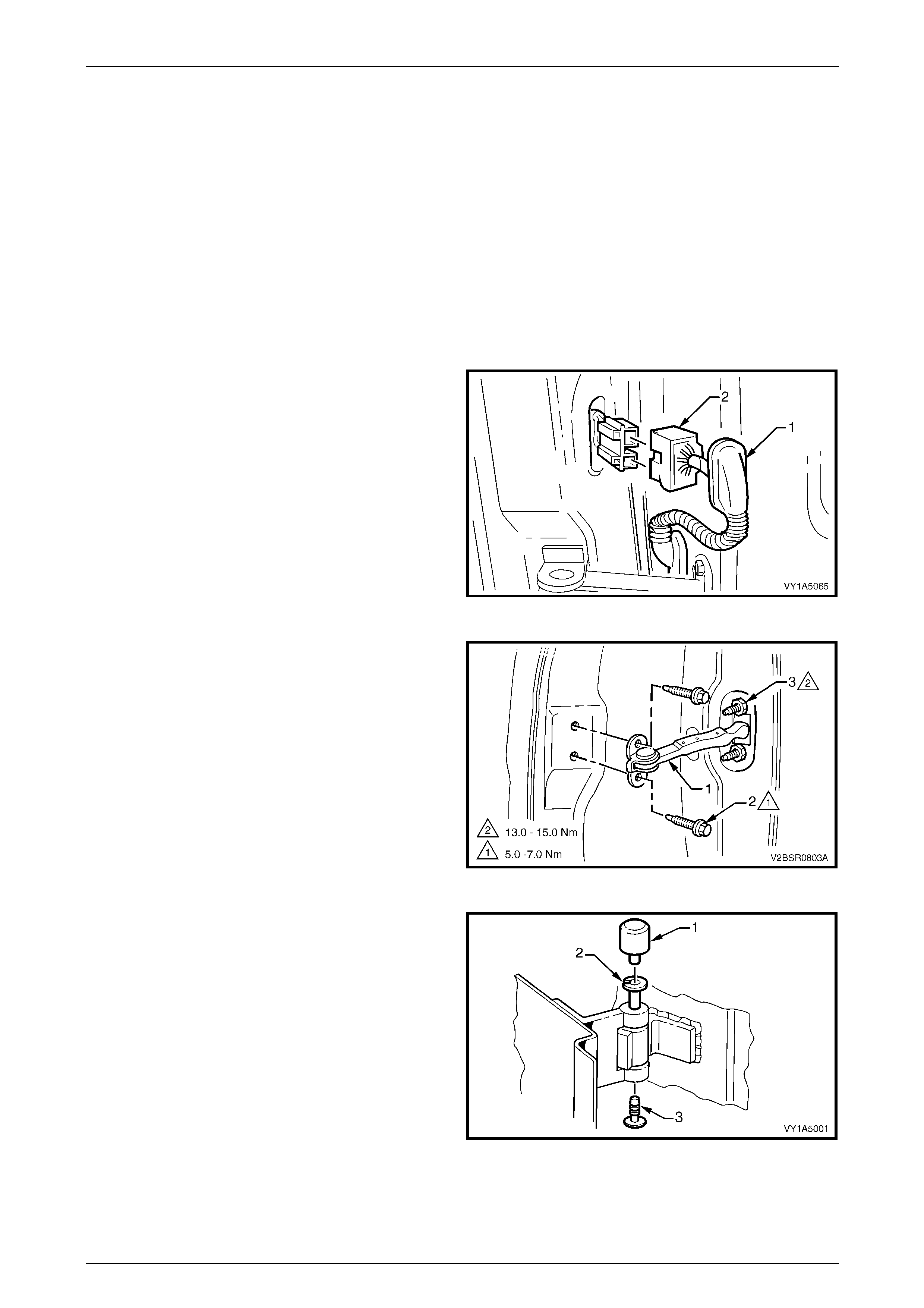
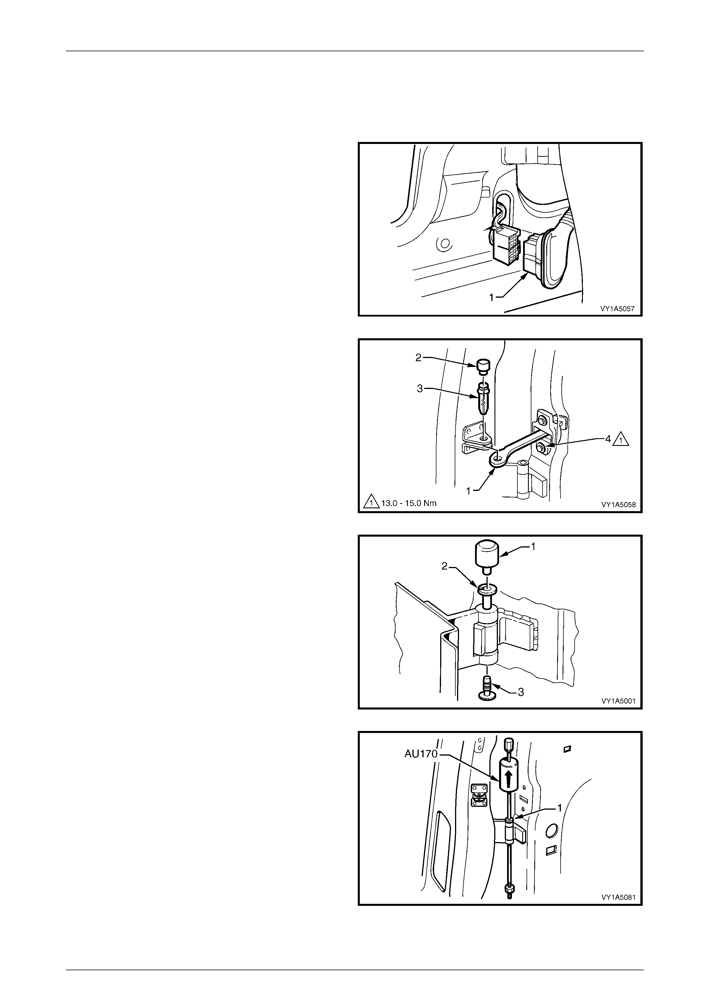
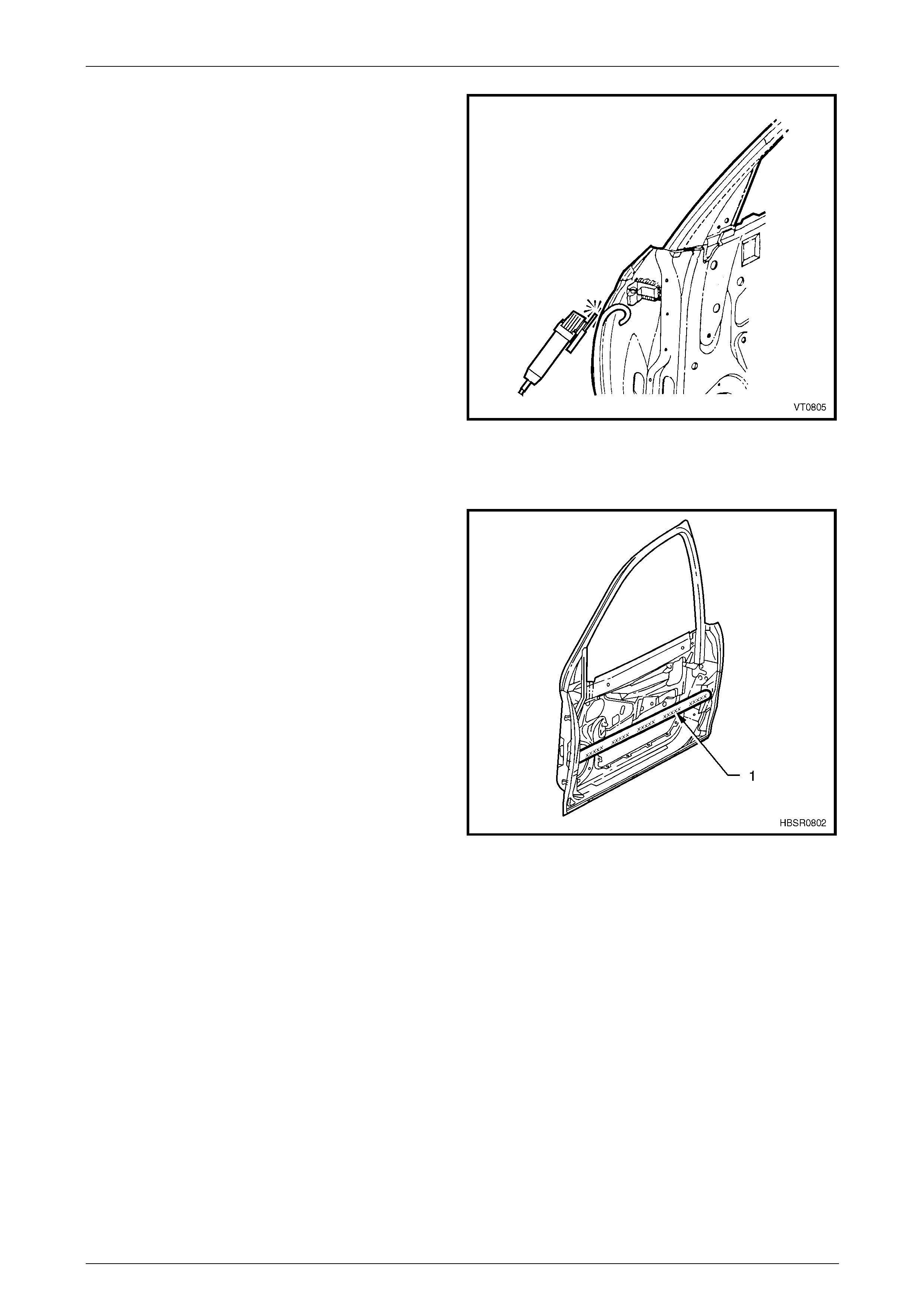
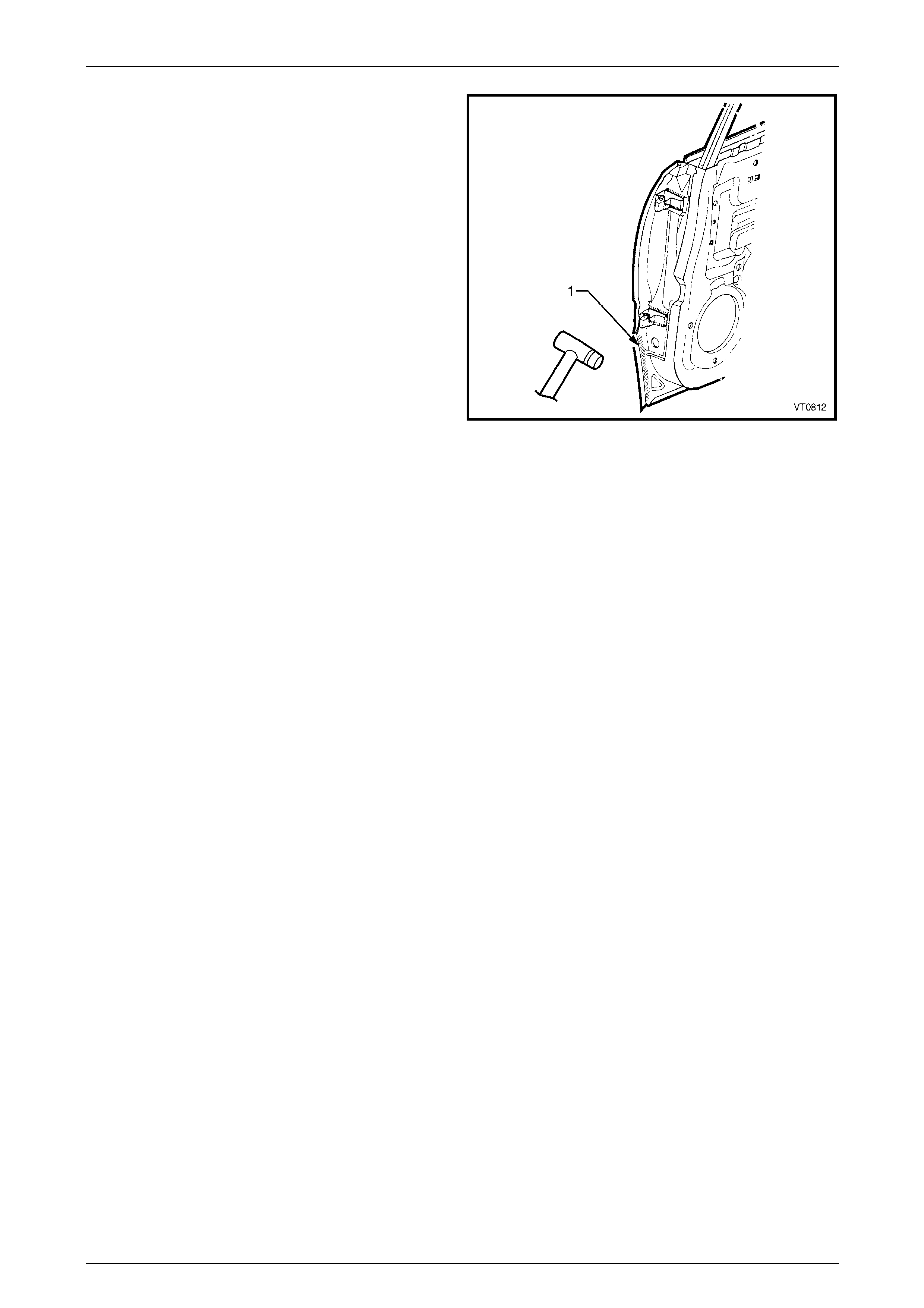
1 Remove the grommet (1) from the door wiring harness
connector plug (2).
2 Remove the connector plug from the pillar by pushing
the tabs and gently pulling o n the wiring harness and
then disconnect.
Figure 8 – 3
3 Disconnect the check assembly (1) from the vehicle by
removing the two screws (2).
NOTE
• If required, remove the two nuts (3),
attaching the check assembly to the door,
allowing access to the hinge pins.
• Ensure the door does not swing freely
causing damage.
Figure 8 – 4
4 Remove the front hinge pin cap (1) and the front hinge
plug (3) from the front hinge pin (2) on the upper an d
lower hinges.
5 Have an assistant support the door or support the
base of the door on a wooden block and a trolley jack.
Figure 8 – 5
8 Doors Page 8-5
Page 8-5
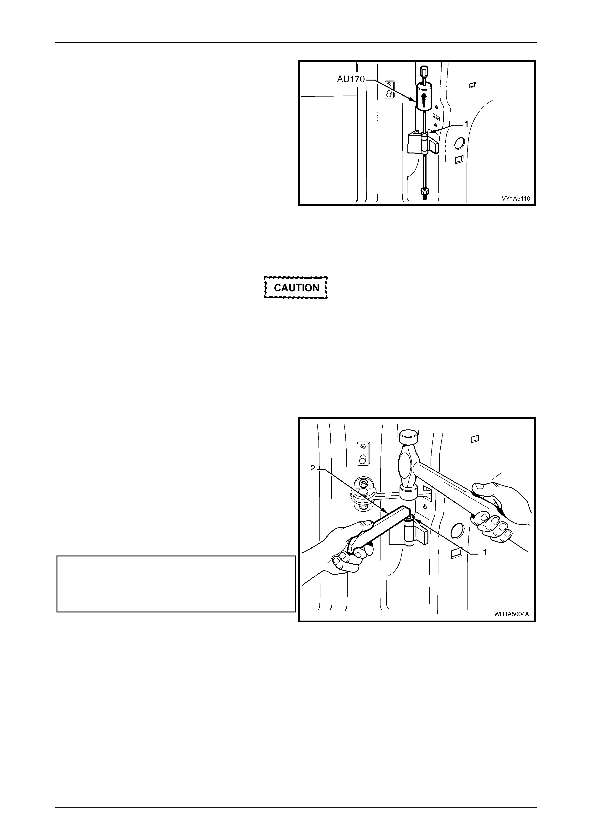
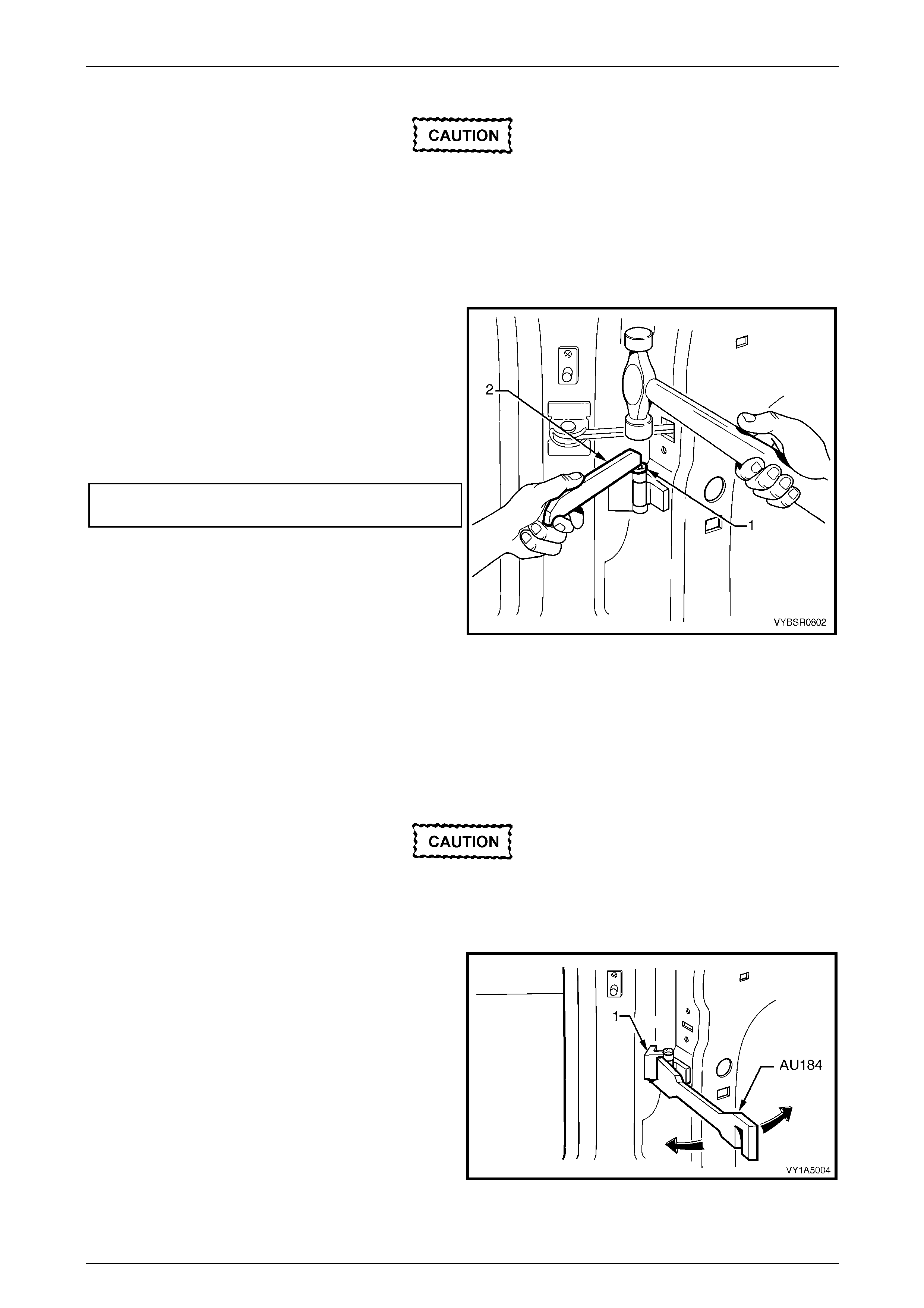
6 Using special tool No. AU170, drive the lower and then
the upper hinge pivot sleeves (1) from the hinges.
7 Remove the door assembly.
Figure 8 – 6
Reinstall
If installing a new door assembly it must be
prepared to maintain original manufacturer
specifications. This includes the application
of joint sealer, hand putty and cavity wax.
Refer to Section 3 Body Construction .
Reinstallation of the front door assembly is the reverse of the removal procedure, noting the following:
1 Apply a Lithium base grease NLGI No. 1 (with 9 % zinc oxide) or equivalent, to the hinge pivot sleeves prior to
installation.
2 Use special tool No. AU303 (2), to install the hinge
pivot sleeves (1).
3 Check the fit of the door and adjust as required,
referring below.
NOTE
Make allowances in the adjustment if the trim
and hardware are not installed.
4 Tighten all retaining screws to the correct torque
specification.
Check assembly to pillar retaining screw
torque specification.....................................5.0 – 7.0 Nm
Check assembly to door retaining nuts
torque specification....................................... 13.0 – 15.0
5 Reinstall the trim and hardware as required. Figure 8 – 7
6 Connect and install the door wiring harness connector to the body wiring harness and refit the grommet.
7 Refit the hinge pivot sleeve dust caps, refer to F igure 8 – 3.
8 Doors Page 8-6
Page 8-6
Adjust
Attention should be given to uniform margins and alignment between the door and surrounding parts when door
adjustments are being carried out.
Uniform margins and alignment of the doors in relation to the body opening can be achieved by setting the appropriate
door hinge. Refer to Section 3 Body Construction .
It is sound practice to remove the door lock striker assembly and allow the door to hang free on the hinges. Set the
hinges as necessary to achieve correct alignment and uniform margins, then reinstall and adjust the striker.
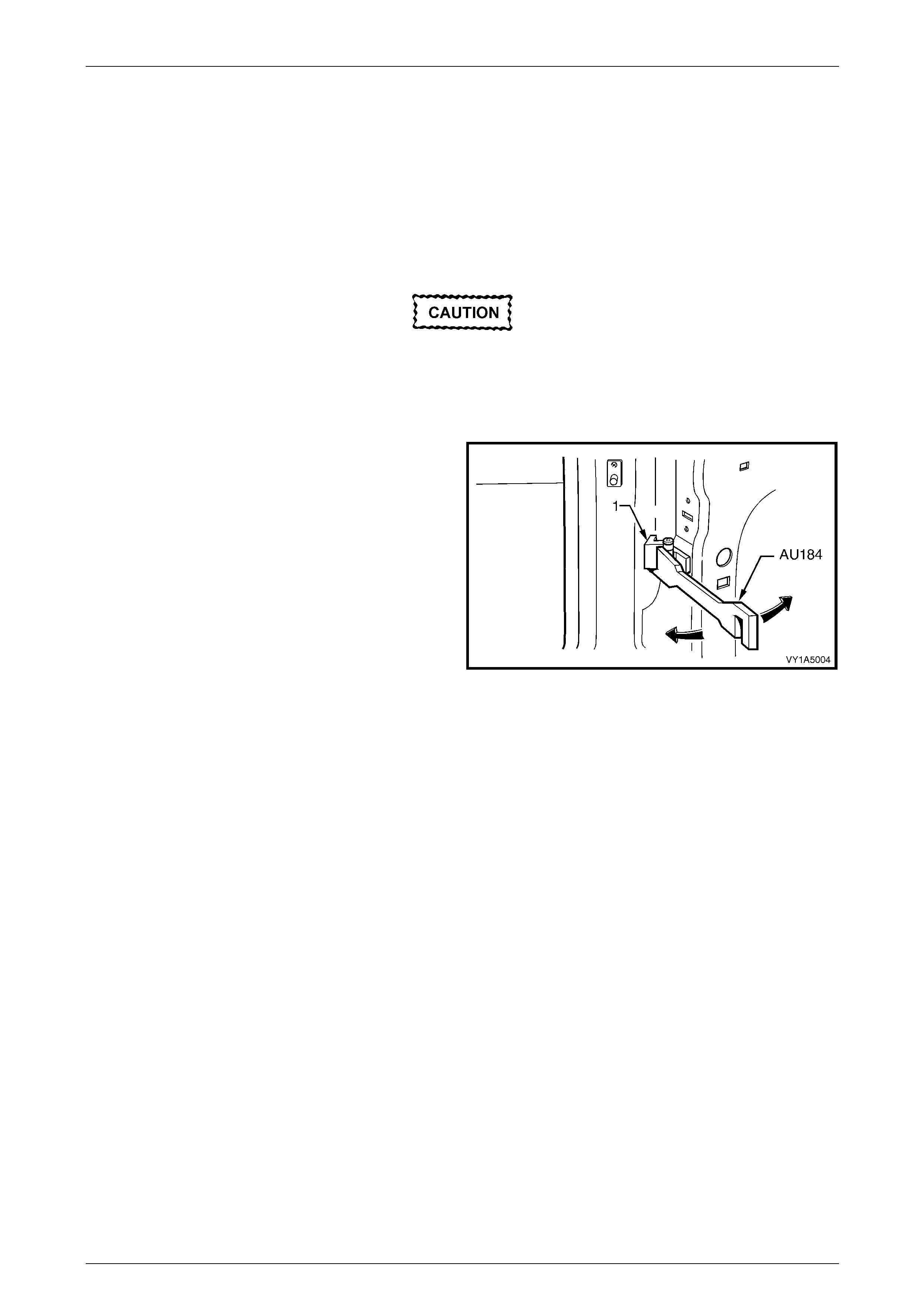
Adjust the doors with the striker assembly
removed. The striker assembly should only be
fitted once satisfactory alignmen t is achieved.
It must not be used to pull the door into the
correct position.
Use special tool No AU184 to set door hinge s by slightly
bending the front door hinge (1) noting the following:
1 Take care when adjusting the doors not to misalign the
hinge pins. Any signific ant misalignment will cause the
pins to shear when the door is open ed or closed.
2 Excessive bending or lever ing of the window frame will
cause damage.
3 Final adjustment must take place when all the door
components and seals are installed.
Figure 8 – 8
8 Doors Page 8-7
Page 8-7
2.2 Rear Door Assembly – Replace
Remove
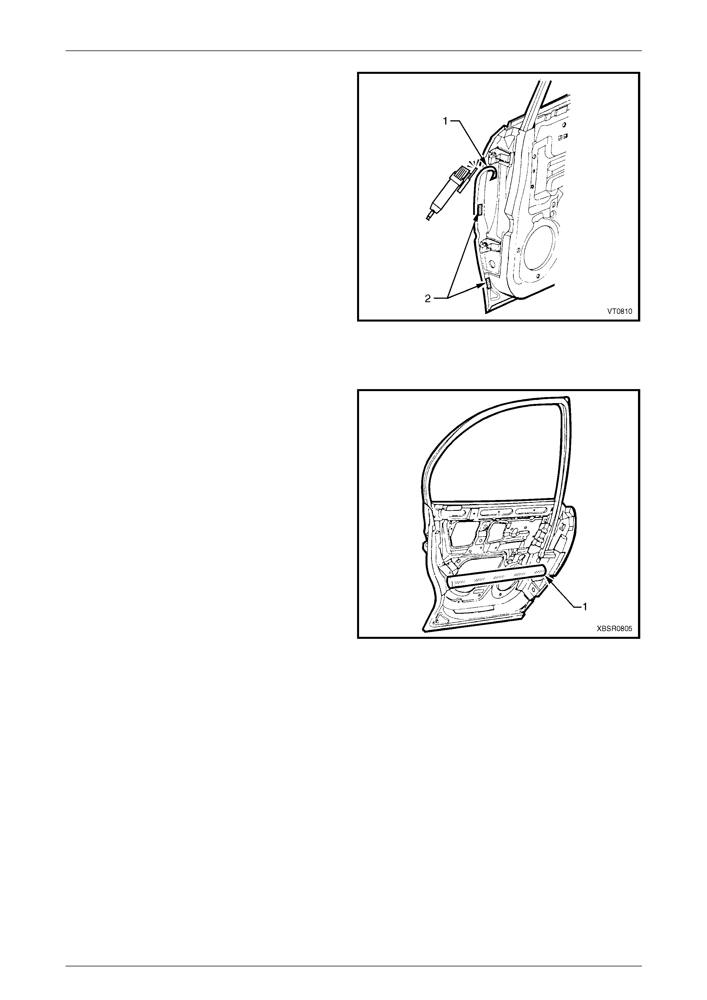
1 Remove the grommet and door wiring harness
connector plug assembly (1).
2 Remove the connector plug from the pillar by gently
pulling on the wiring harness and then disconnect.
Figure 8 – 9
3 Disconnect the rear door check assembly (1) from the
vehicle, by removing the rear door check link bracket
cover (2) and then the rear door check link pin (3).
NOTE
• If required, remove the two screws (4)
attaching the check-link assembly to the do or
to allow access to the hinge pins.
• Ensure the door does not swing freely
causing damage.
Figure 8 – 10
4 Remove the rear hinge pin ca p (1) and the rear hinge
plug (3) from the rear hinge pin (2) on the upper and
lower hinges.
5 Have an assistant support the door or support the
base of the door on a wooden block and a trolley jack.
Figure 8 – 11
6 Using special tool No. AU170, drive the lower and then
the upper hinge pivot sleeves (1) from the hinges.
7 Remove the door assembly.
Figure 8 – 12
8 Doors Page 8-8
Page 8-8
Reinstall
If installing a new door assembly it must be
prepared to maintain original manufacturer
specifications. This includes the application
of joint sealer, hand putty and cavity wax,
refer to Section 3 Body Construction .
Reinstallation of the front door assembly is the reverse of the removal procedure, noting the following:
1 Apply a Lithium base grease NLGI No. 1 (with 9 % zinc oxide) or equivalent, to the hinge pivot sleeves prior to
installation.
2 Use special tool No. AU303 (2), to install the hinge
pivot sleeves (1).
3 Check the fit of the door and adjust as required,
referring below. NOTE
Make allowances in the adjustment if the trim
and hardware are not installed.
4 Tighten all retaining screws to the correct torque
specification.
Check assembly to door retaining screw
torque specification....................................... 13.0 – 15.0
5 Reinstall the trim and hardware as required.
6 Connect and install the door wiring harness connector
to the body wiring harness and refit the grommet.
7 Refit the hinge pivot sleeve dust caps, refer to
Figure 8 – 11.
Figure 8 – 13
Adjust
Attention should be given to uniform margins and alignment between the door and surrounding parts when door
adjustments are being carried out.
Uniform margins and alignment of the doors in relation to the body opening can be achieved by setting the appropriate
door hinge. Refer to Section 3 Body Construction .
It is sound practice to remove the door lock striker assembly and allow the door to hang free on the hinges. Set the
hinges as necessary to achieve correct alignment and uniform margins, then reinstall and adjust the striker.
Adjust the doors with the striker assembly
removed. The striker assembly should only be
fitted once satisfactory alignmen t is achieved.
It must not be used to pull the door into the
correct position.
Use special tool No AU184 to set door hinge s by slightly
bending the front door hinge (1) noting the following:
1 Take care when adjusting the doors not to misalign the
hinge pins. Any signific ant misalignment will cause the
pins to shear when the door is open ed or closed.
2 Excessive bending or lever ing of the window frame will
cause damage.
3 Final adjustment must take place when all the door
components and seals are installed.
Figure 8 – 14
8 Doors Page 8-9
Page 8-9
2.3 Door Hinge (Body Side) – Replace
Remove
1 Remove the appropriate door from vehicle as previously described.
2 Carefully grind the MIG weld from around the hinge flap.
3 Remove the hinge and gr ind any remaining MIG weld as required.
NOTE
Do not cut into the door opening frame pane l.
Reinstall
1 Remove any trim and components from behind the pillar area as requir ed. Refer to the appropriate Sections in the
MY2005 WL Service Information.
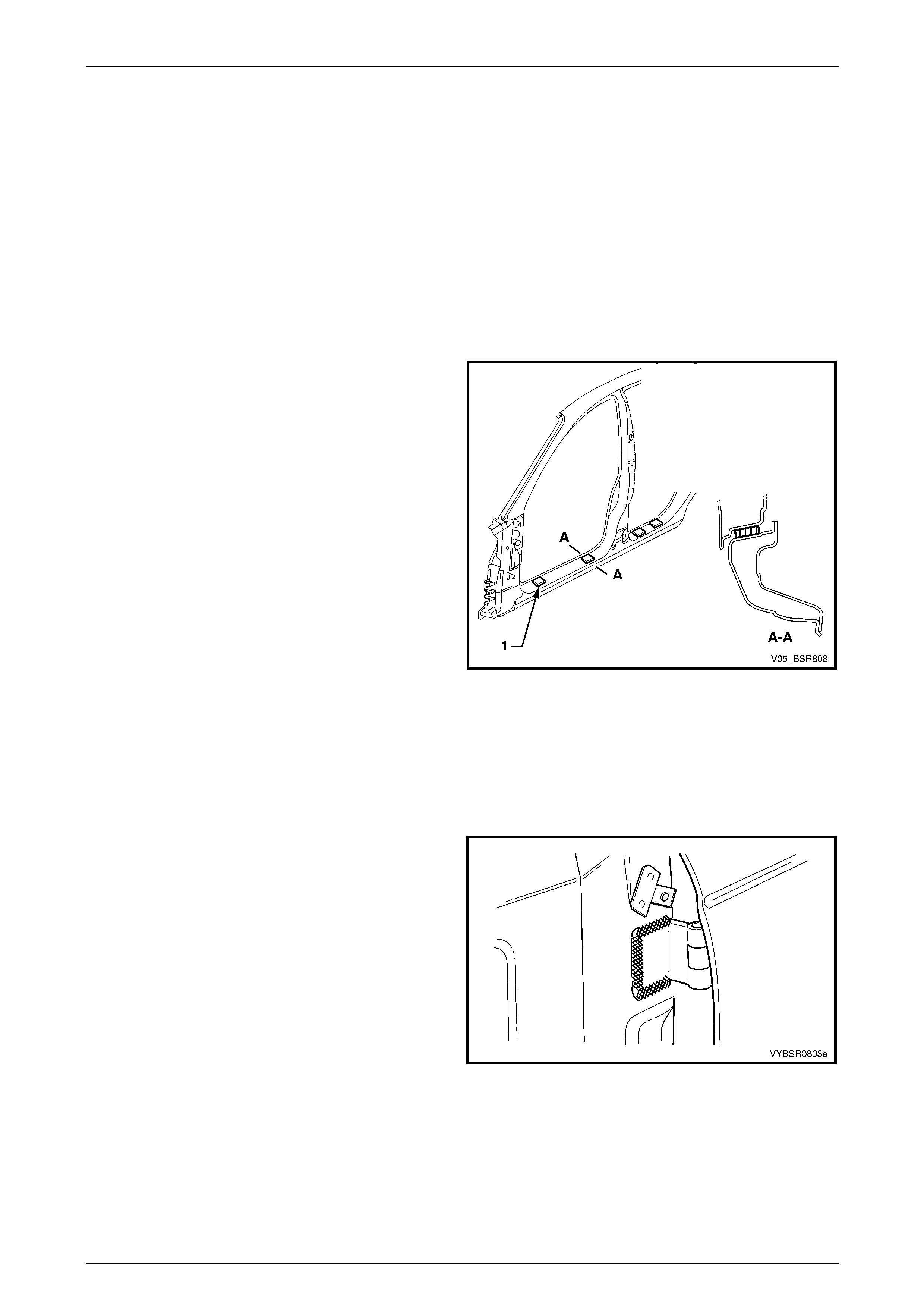
2 Construct two spacers (1) from timber, 10 mm thick.
3 Tape the spacers in the positions shown near the
dimples in the flange of the rocker panel, either for the
front or rear doors. NOTE
If both front and rear door hinge flaps require
replacing, begin with the rear door.
4 If not already done so, fit the hinge flaps onto the door
assembly.
5 With the aid of an assistant, place the door assembly
in position on the vehicle and adjust its position with
shims as required.
Refer to Section 3 Body Construction for
specifications.
Figure 8 – 15
NOTE
Position the rear of the door approximately 3 mm
higher than specified to allow for the additional
weight of the door hardware and trim
components.
6 Tack weld the upper and lower hinge fla ps to the do or opening frame assembly.
7 Remove the spacer blocks and shims and recheck the door alignment. Rectify as required.
8 Complete welding the hinge flap.
9 Remove the door assembly from the hinge as
previously described.
10 Grind or sand the weld to provide a smooth finish.
11 Refinish and paint the hing e flaps and surrounding
area as required.
Refer to Section 3 Body Construction .
12 Apply a smooth bead of Joint Sealer (Item 3) around
all sides of the flap before the top paint coats to
maintain corrosion protection under the flap,
refer to Section 3 Body Construction .
13 Apply Cavity Wax (Item 8) as required to the inside of
any box sections or areas i na ccessible to paint,
refer to Section 3 Body Construction . Figure 8 – 16
8 Doors Page 8-10
Page 8-10
2.4 Front Door Outer Panel – Replace
The door impact beams must not be heated,
welded or straightened in any way, due to
their critical role in driver/passenger safety.
Damage to the impact beams will necessitate
the replacement of the entire door assembly.
Remove
1 Disassemble the door trim and hardware as required. Refer to Section 1A5 Front And Rear Door Assemblies in the
MY2005 WL Service Information.
2 Remove the front door from the vehicle, refer to 2.1 Front Door Assembly – Replace.
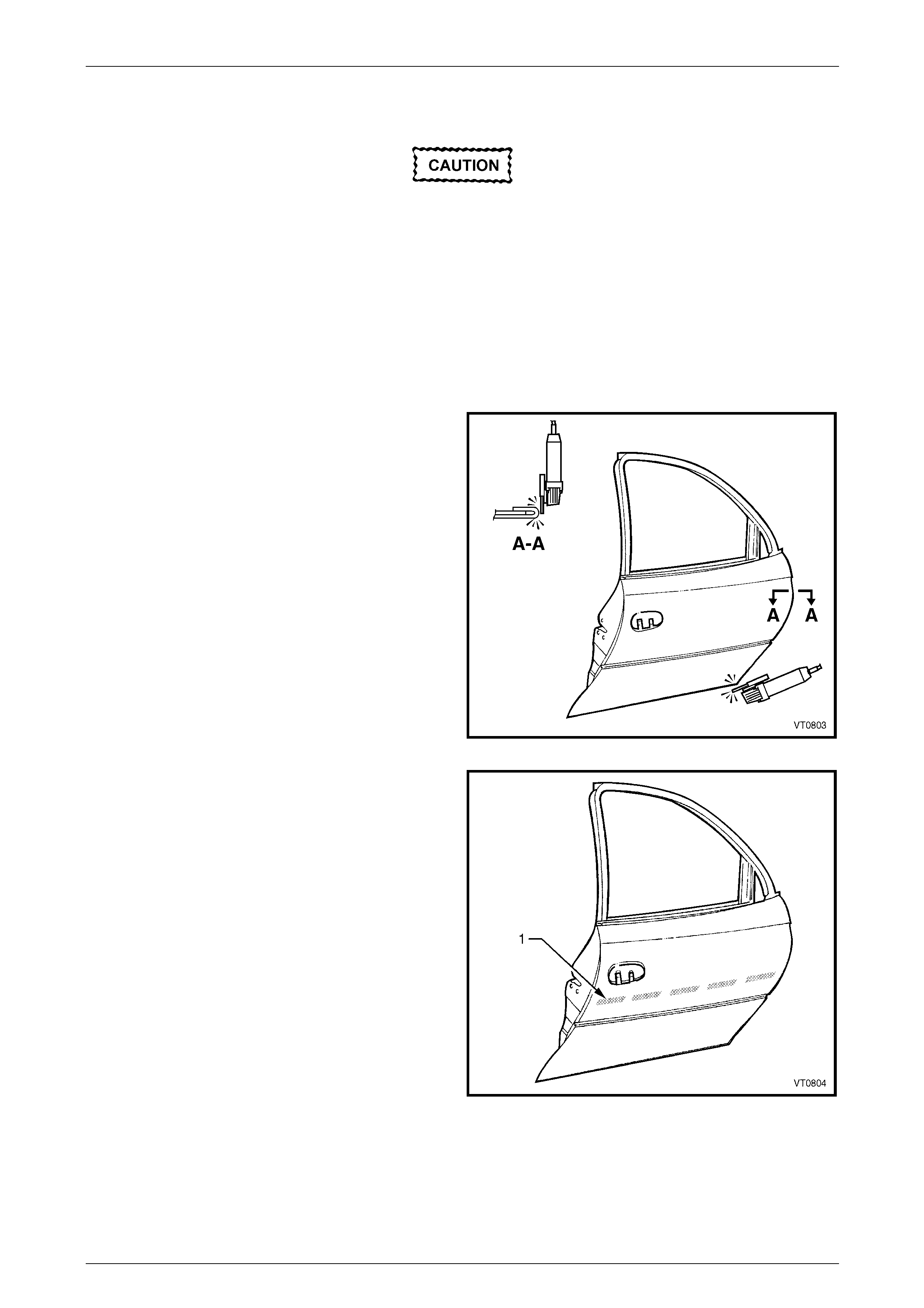
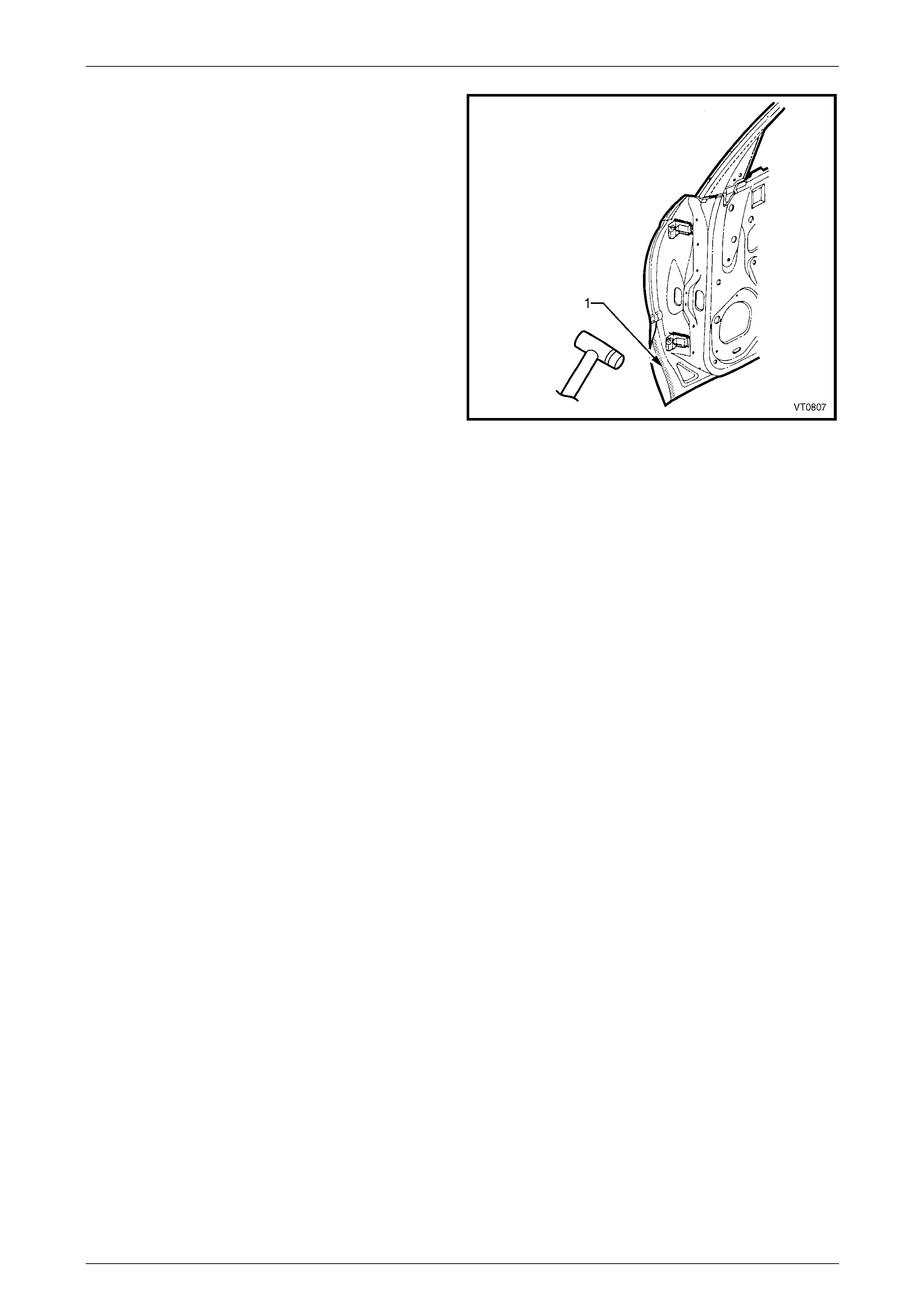
3 Remove the edge of the hem by grindin g or sand ing,
along the front, rear and lower edges of the door.
Figure 8 – 17
4 Soften the adhesive between the door outer panel and
the door impact beam using a heat gun in the areas
(1).
5 Separate the door outer panel from the door i nner.
Figure 8 – 18
8 Doors Page 8-11
Page 8-11
6 Remove the hemming strip from the door inn er pan el
by grinding or chiselling away the metal and the
adhesive.
7 Repair any damage to the d oor inner panel as
required. Remove any residual adhesive from the hem
and door impact beam.
8 Prepare and prime and bare metal.
9 Test fit the door inner panel onto the vehicle.
Figure 8 – 19
Replace
1 Apply five equally spaced beads (1) of Anti-flutter
Adhesive (Item 5) to the impact beam, refer to
Section 3 Body Construction .
Figure 8 – 20
8 Doors Page 8-12
Page 8-12
2 Apply Structural Adhesive (1) (Item 6) to the mating
surfaces around the hem on the door inner panel,
refer to Section 3 Body Construction .
3 Clamp the outer panel in position and fold over the
hemming to attach the outer panel firmly to the inner
shell.
NOTE
This procedure must be performed carefully to
avoid damaging the panel surface. The use of
body filler around the outer edges of the door
outer panel to rectify hammering damage is
considered unacceptable.
4 Test fit the door onto the vehicle and ensure the panel
margins are within specification,
refer to Section 3 Body Construction .
5 Remove the door.
6 Refinish and paint the door as required.
Refer to Section 3 Body Construction . Figure 8 – 21
7 Apply Joint Sealer (Item 3) as required. Refer to Section 3 Body Construction .
8 Apply Cavity Wax (Item 8) as required to the inside of any box sections or areas inaccessible to paint,
refer to Section 3 Body Construction .
9 Install the door onto the vehicle and adjust as required, refer to 2.1 Front Door Assembly – Replace.
10 Replace the door trim and hardware as required. Refer to Section 1A5 Front And Rear D oor Assemblies in the
MY2005 WL Service Information.
8 Doors Page 8-13
Page 8-13
2.5 Rear Door Outer Panel – Replace
The door impact beams must not be heated,
welded or straightened in any way, due to
their critical role in driver/passenger safety.
Damage to the impact beams will necessitate
the replacement of the entire door assembly.
Remove
1 Disassemble the door trim and hardware as required. Refer to Section 1A5 Front And Rear Door Assemblies in the
MY2005 WL Service Information.
2 Remove the rear door from the vehicle, refer to 2.2 Rear Door Assembly – Replace.
3 Remove the edge of the hem by grindin g or sand ing,
along the front, rear and lower edges of the door.
Figure 8 – 22
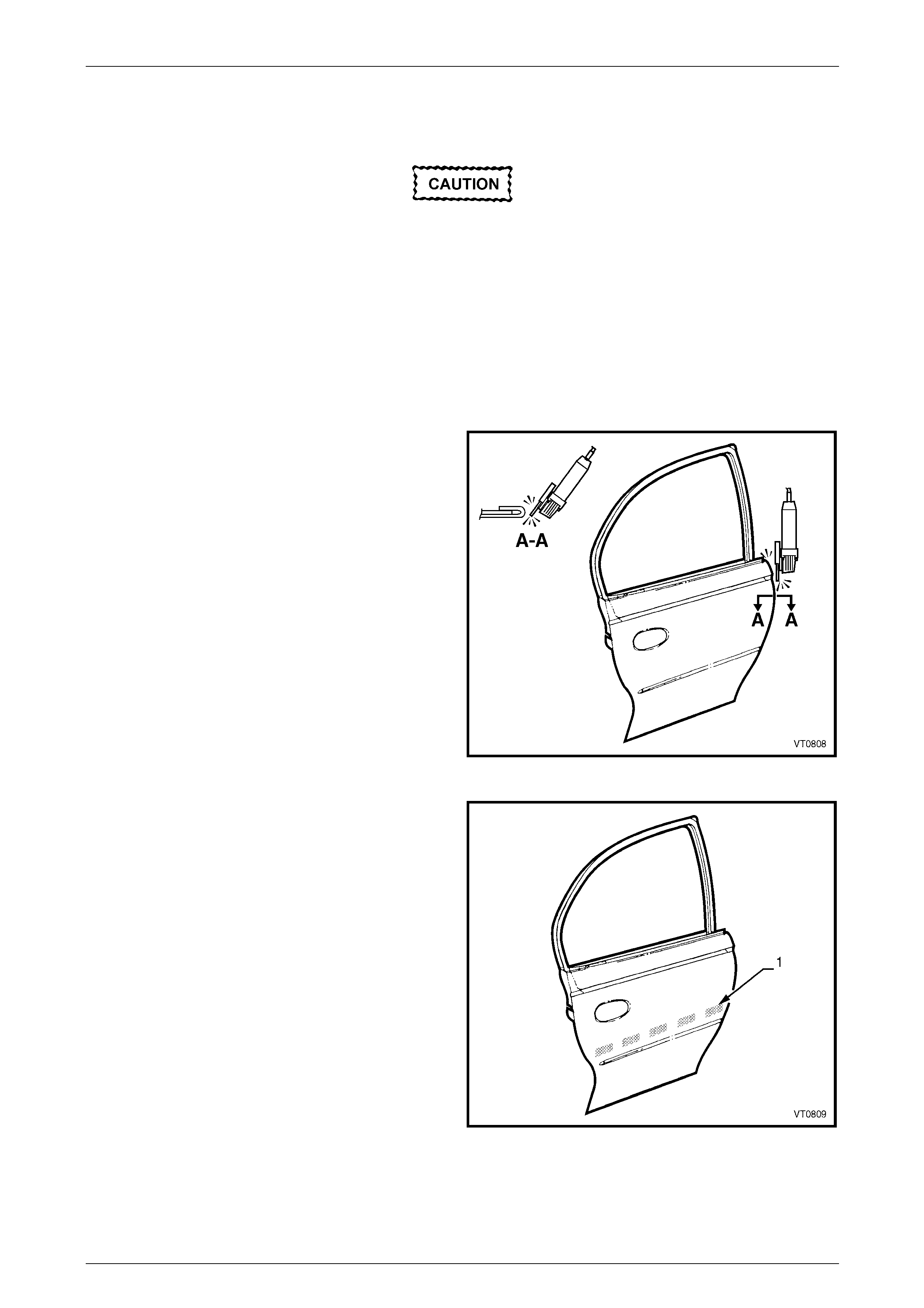
4 Soften the adhesive between the door outer panel and
the door impact beam using a heat gun in the areas
(1).
5 Separate the door outer panel from the door i nner.
Figure 8 – 23
8 Doors Page 8-14
Page 8-14
6 Remove the hemming strip (1) from the door inner
panel by grinding or chiselling away the metal strip
and the adhesive.
NOTE
There are two tack welds (2) attaching the
hemming to the door inner panel on the front
edge of the rear door. These welds must be
ground off to remove the hemming from this
area.
7 Repair any damage to the d oor inner panel as
required. Remove any residual adhesive from the hem
and door impact beam.
8 Prepare and prime and bare metal.
9 Test fit the door inner panel onto the vehicle.
Figure 8 – 24
Replace
1 Apply five equally spaced beads (1) of Anti-flutter
Adhesive (Item 5) to the impact beam, refer to
Section 3 Body Construction .
Figure 8 – 25
8 Doors Page 8-15
Page 8-15
2 Apply Structural Adhesive (1) (Item 6) to the mating
surfaces around the hem on the door inner, refer to
Section 3 Body Construction .
3 Clamp the outer panel in position and fold over the
hem to attach the outer panel firmly to the inner panel.
NOTE
This procedure must be performed carefully to
avoid damaging the panel surface. The use of
body filler around the outer edges of the door
outer panel to rectify hammering damage is
considered unacceptable.
Figure 8 – 26
4 Test fit the door onto the vehicle and ensure the panel margins are within specification, refer to
Section 3 Body Construction .
5 Remove the door.
6 Place two MIG tack welds attaching the front hemming to the door inner panel.
NOTE
Place several wet rags on the surrounding
surface and the outer panel to minimise heat
distortion.
7 Refinish and paint the door as required. Refer to Section 3 Body Construction .
8 Apply Joint Sealer (Item 3) as required. Refer to Section 3 Body Construction .
9 Apply Cavity Wax (Item 8) as required to the inside of any box sections or areas inaccessible to paint,
refer to Section 3 Body Construction .
10 Install the door onto the vehicle and adjust as required, refer to 2.2 Rear Door Assembly – Replace.
11 Install the door trim and hardware as requir ed. Refer to Section 1A5 F r ont And Rear Door Assemblies in the
MY2005 WL Service Information.

8 Doors Page 8-16
Page 8-16
3 Torque Wrench Specifications
Check assembly to pillar retaining screw.......................................5.0 – 7.0 Nm
Check assembly to door retaining nuts......................................13.0 – 15.0 Nm
8 Doors Page 8-17
Page 8-17
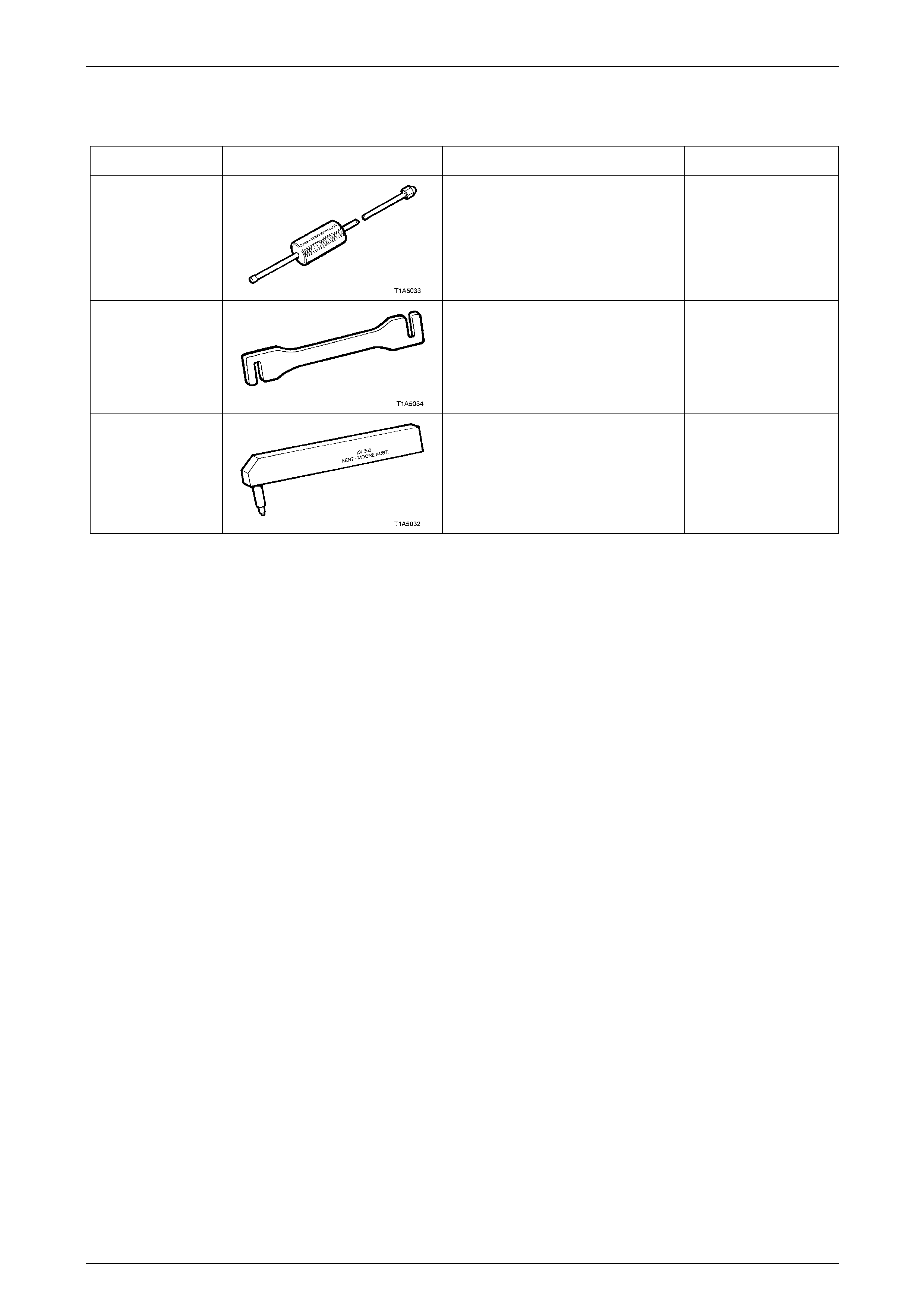
4 Special Tools
Tool Number Illustration Description Tool Classification
AU170
Door Hinge Pin Removal Tool
Used for removing door hinge pivot
sleeves
Available
AU184
Door Hinge Setting Tool
Used to adjust door alignment Desirable
AU303
Door Hinge Sleeve Installer
Used to install door hinge piv ot
sleeves
Available