10 Body Rear Page 10–1
Page 10–1
Section 10
Body Rear
ATTENTION
Before performing any service operation or other procedure described in this Section, refer to Section 2
Precautions in this Supplement and Section 00 Warnings, Cautions and Notes in the MY2005 WL Service
Information for correct workshop practices with regard to safety and/or property damage.
The structure of the body shell has been
developed using complex design and
development techniques. In addition to
meeting all required standards, the vehicle
body is also a critical part of the overall safety
systems. It is therefore imperative the repair
procedures described here are adhered to
during all vehicle body repairs.
1 General Information ...............................................................................................................................3
1.1 Body Rear Components........................................................................................................................................ 3
2 Service Operations.................................................................................................................................5
2.1 Rear End Lower Panel – Replace ......................................................................................................................... 5
Remove................................................................................................................................................................... 5
Replace................................................................................................................................................................... 6
2.2 Rear End Panel Assembly – Replace................................................................................................................... 8
Remove................................................................................................................................................................... 8
Replace................................................................................................................................................................. 10
2.3 Fuel Tank Support Reinforcement Assembly – Replace.................................................................................. 12
Remove................................................................................................................................................................. 12
Replace................................................................................................................................................................. 13
2.4 Rear Compartment Floor Panel Outer Extension – Replace............................................................................ 14
Remove................................................................................................................................................................. 14
Replace................................................................................................................................................................. 15
2.5 Rear Compartment Floor Panel Assembly – Replace....................................................................................... 16
Remove................................................................................................................................................................. 16
Replace................................................................................................................................................................. 17
2.6 Rear Window Panel Assembly – Replace.......................................................................................................... 19
Remove................................................................................................................................................................. 19
Replace................................................................................................................................................................. 20
2.7 Rear Seat Back Panel Extension Assembly or Rear Wheelhouse Inner Panel Assembly – Replace........... 22
Remove................................................................................................................................................................. 22
Replace................................................................................................................................................................. 24
2.8 Rear Compartment Lid Strut Bracket Assembly – Replace............................................................................. 26
Remove................................................................................................................................................................. 26
Replace................................................................................................................................................................. 27
2.9 Crossmember Assembly No. 2 – Replace ......................................................................................................... 28
Remove................................................................................................................................................................. 28
Replace................................................................................................................................................................. 29

10 Body Rear Page 10–2
Page 10–2
2.10 Rear Floor Panel Outer Extension – Replace.................................................................................................... 30
Remove................................................................................................................................................................. 30
Replace................................................................................................................................................................. 31
2.11 Rear Tie Down Assembly – Replace .................................................................................................................. 32
Remove................................................................................................................................................................. 32
Replace................................................................................................................................................................. 33
2.12 Rear Bumper Impact Bar Brace Assembly – Replace ...................................................................................... 34
Remove................................................................................................................................................................. 34
Replace................................................................................................................................................................. 35
2.13 Rear Side Rail Assembly – Replace................................................................................................................... 36
Remove................................................................................................................................................................. 36
Replace................................................................................................................................................................. 38
2.14 Rear Floor Panel Assembly – Replace............................................................................................................... 40
Remove................................................................................................................................................................. 40
Replace................................................................................................................................................................. 43
2.15 Rear Floor Panel Reinforcement – Replace....................................................................................................... 46
Left-hand Side...................................................................................................................................................... 46
Remove............................................................................................................................................................ 46
Replace............................................................................................................................................................ 46
Right-hand Side ................................................................................................................................................... 47
Remove............................................................................................................................................................ 47
Replace............................................................................................................................................................ 47
10 Body Rear Page 10–3
Page 10–3
1 General Information
This Section describes replacement procedures for the rear section comp onents of the body structure. Removal of bolt-
on and mechanical components is not covered. Reference must be made to the appropri ate Sections in the MY2005 WL
Service Information.
When repairing the rear of the vehicle, care must be taken to ensure the structure is returned to its original production
configuration.
NOTE
It is imperative that the correct body adhesives,
sealers, deadeners and cavity waxes are used
when repairing the body structure, refer to
Section 3 Body Construction for details of the
correct materials and their commercially available
equivalents.
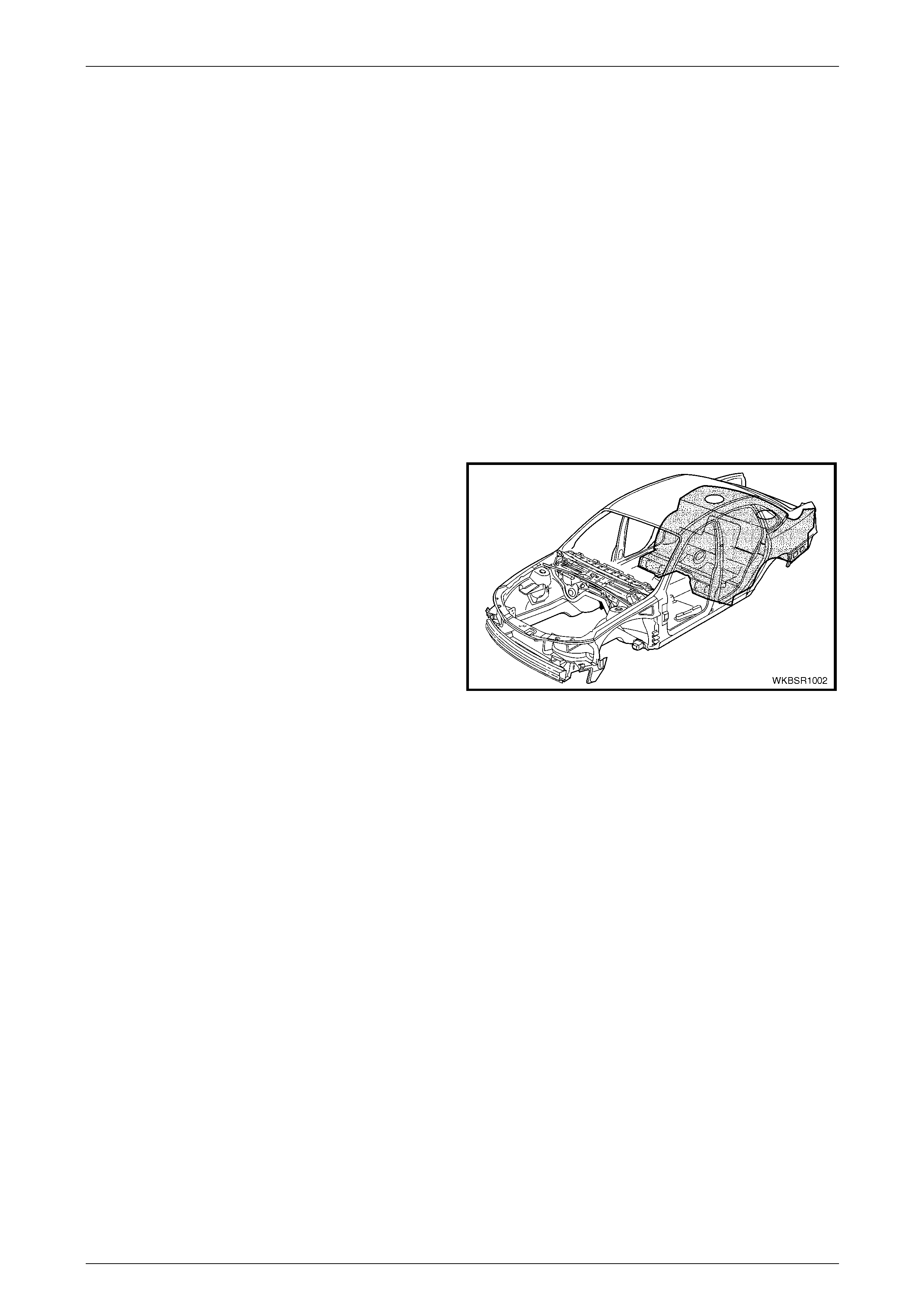
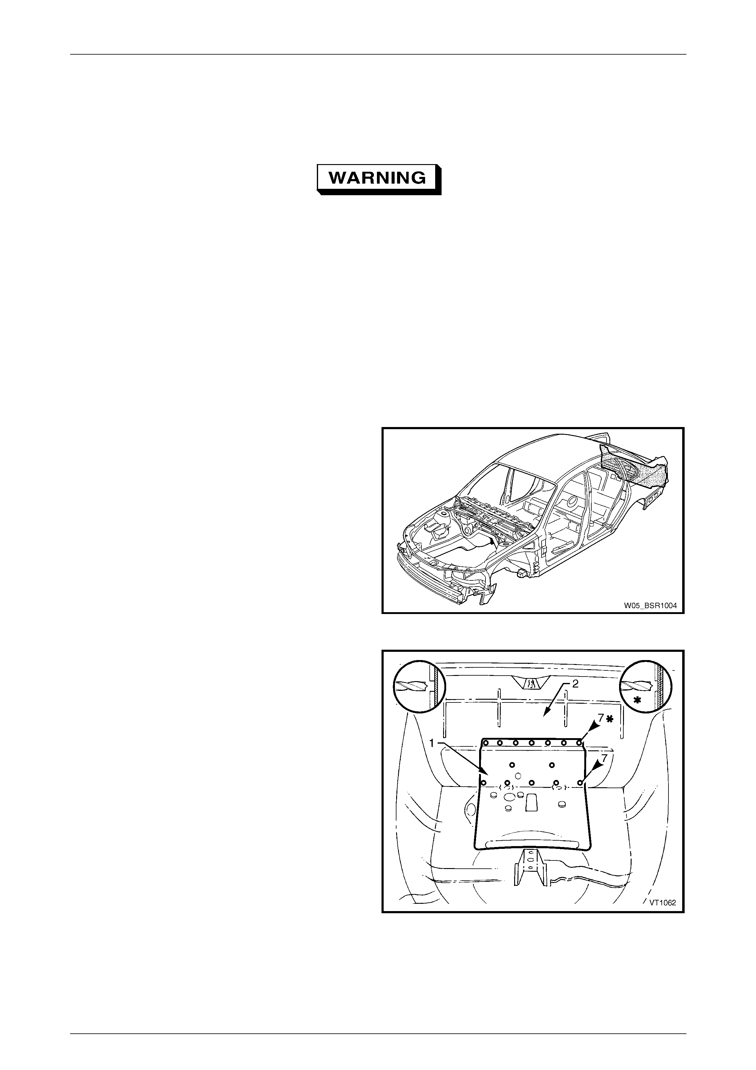
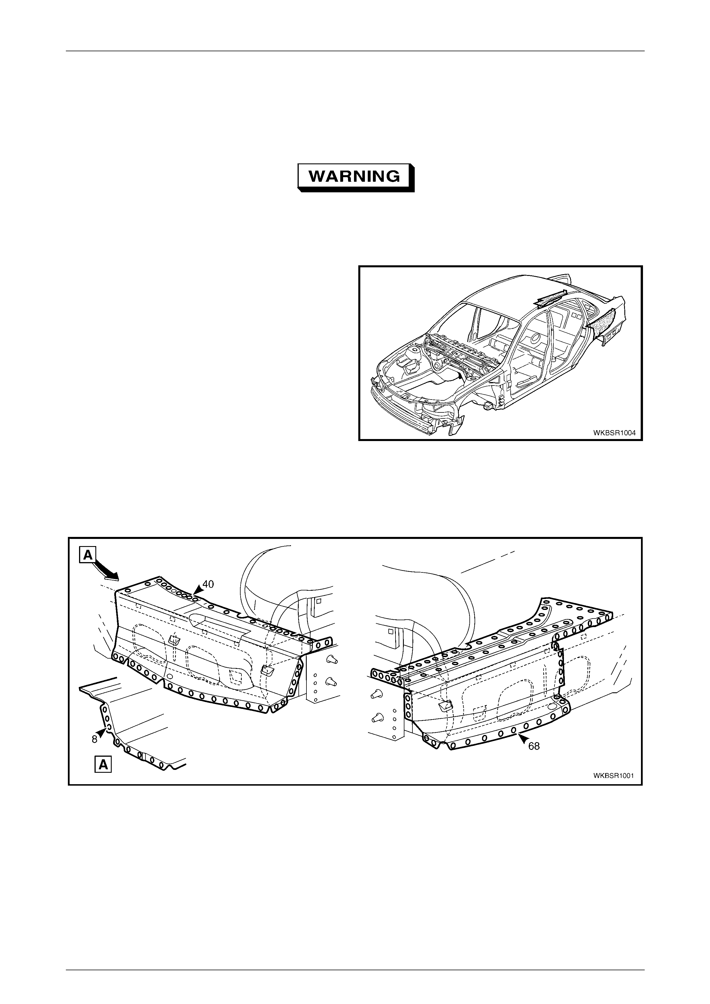
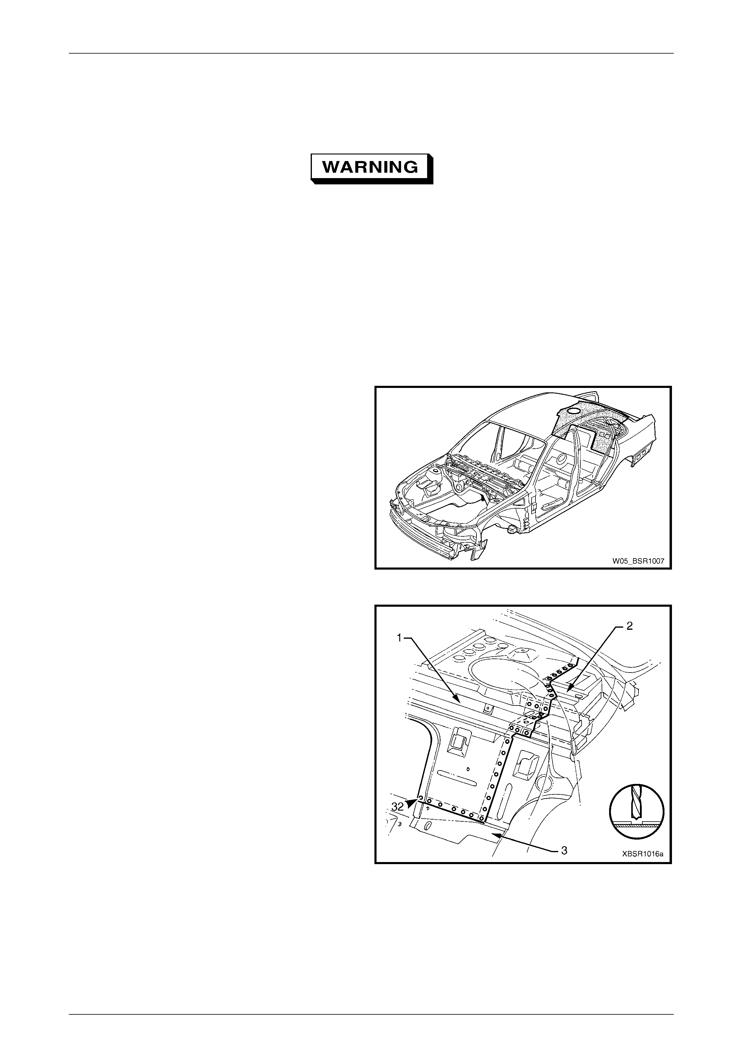
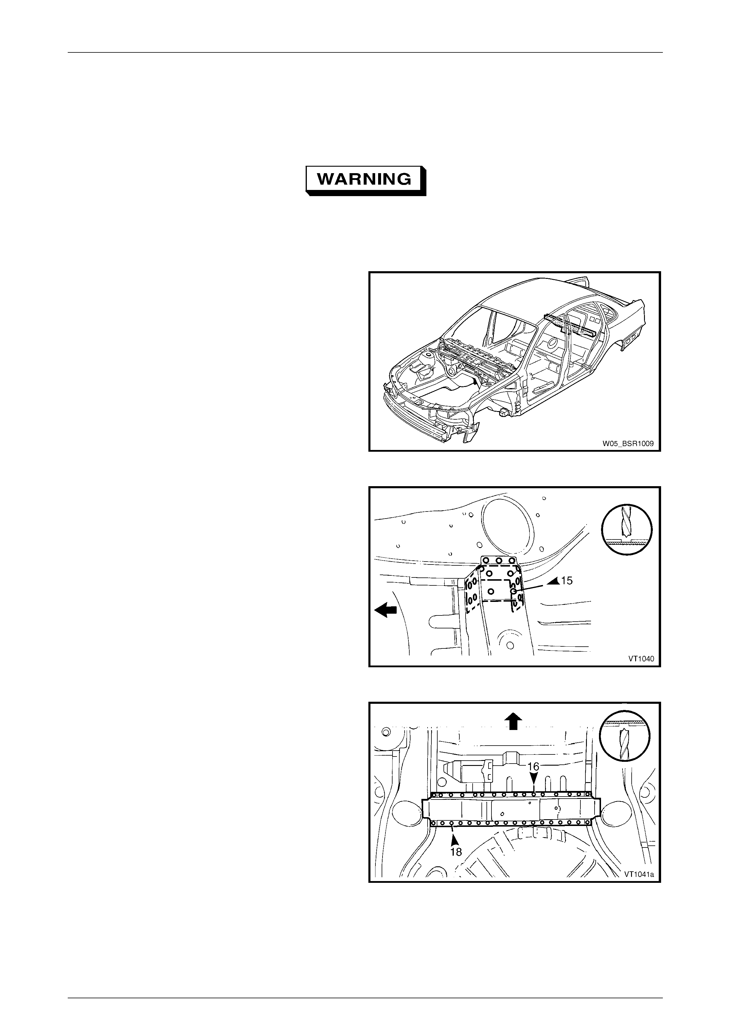
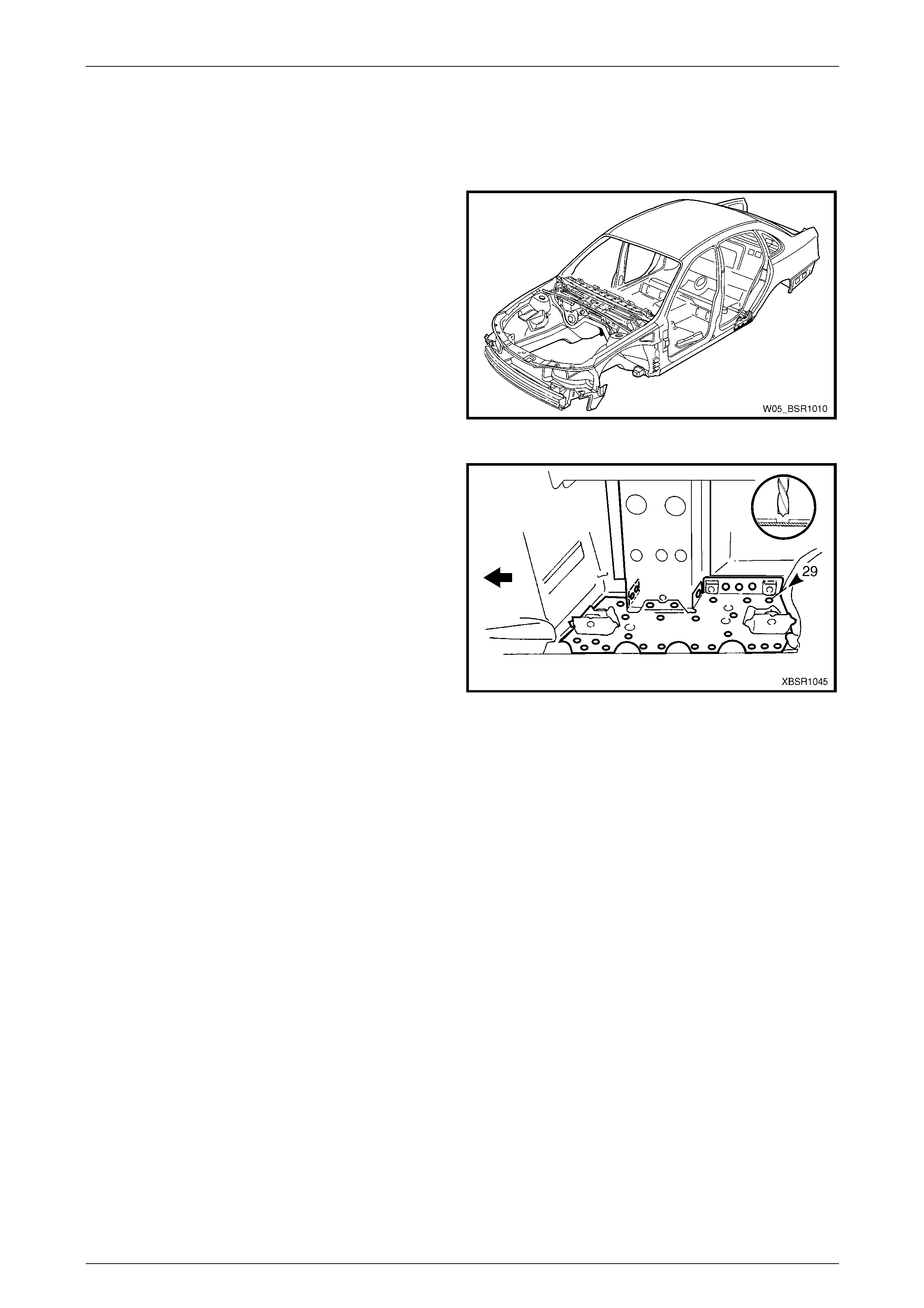
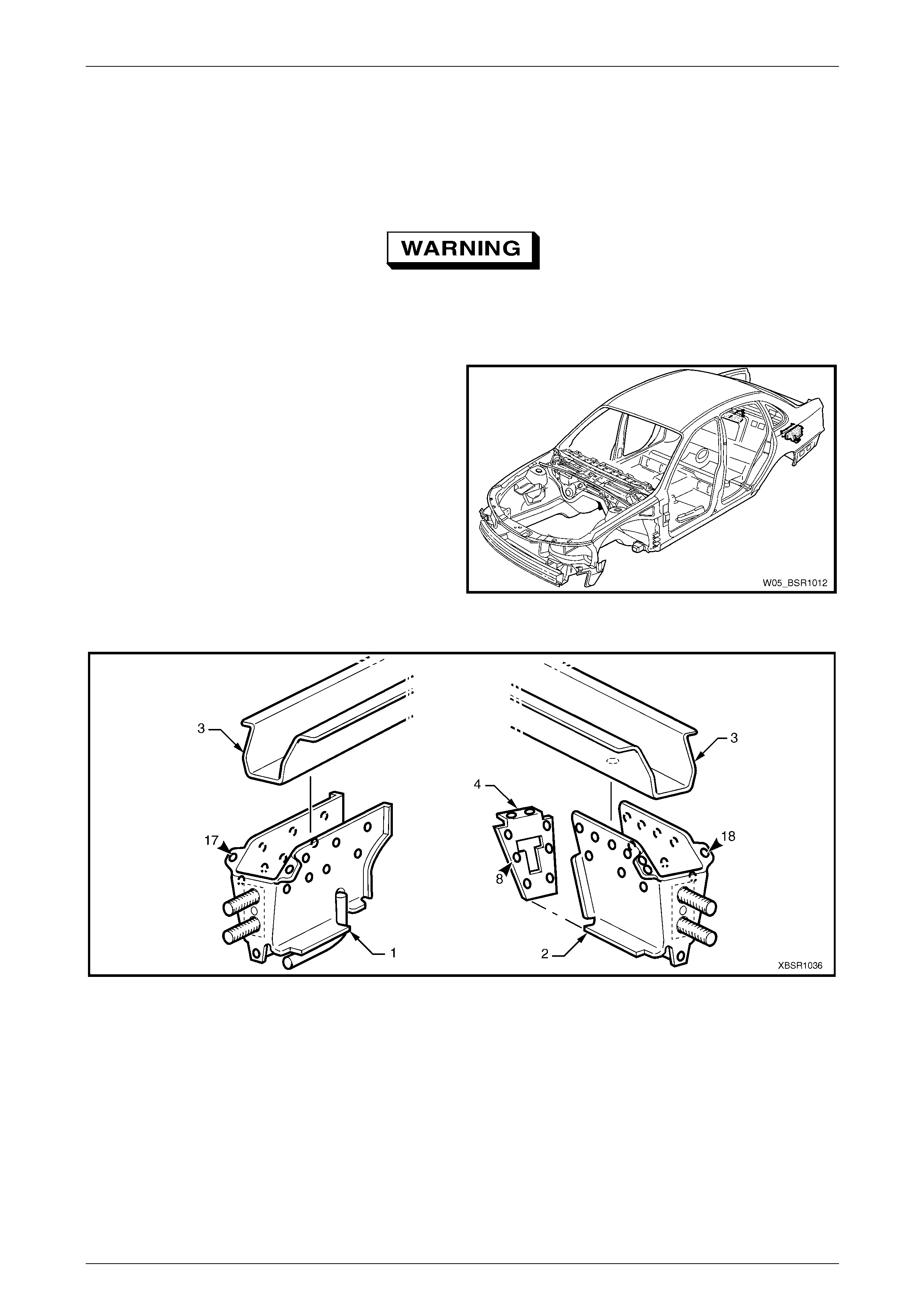
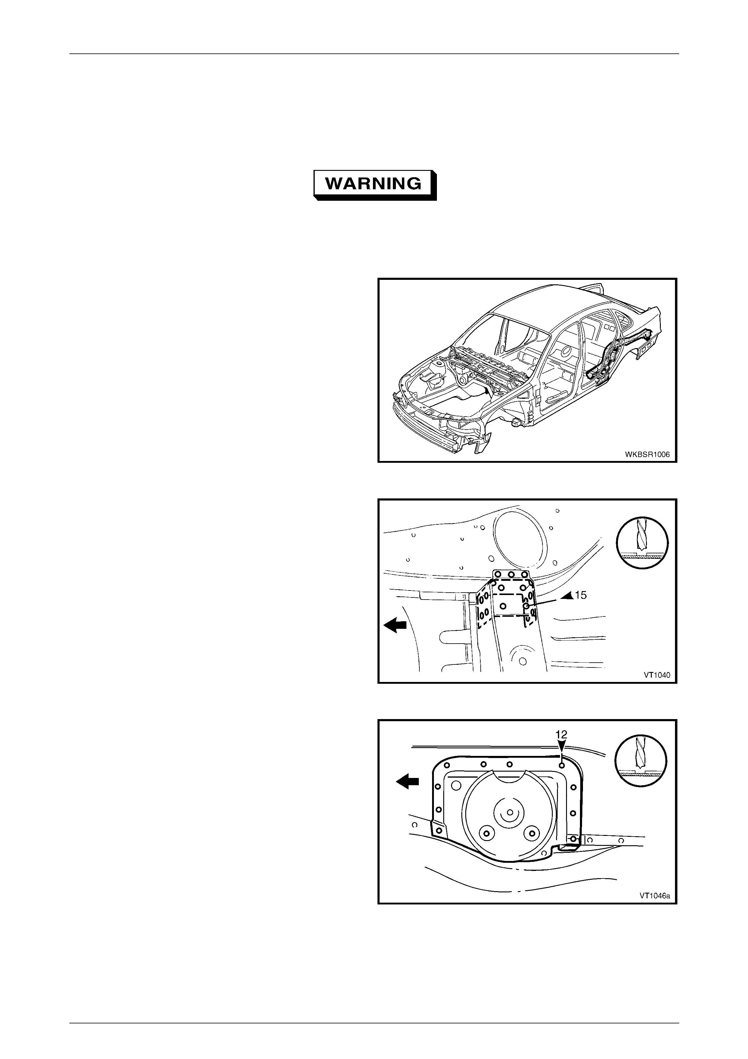
1.1 Body Rear Components
The shaded components shown are those dealt with in this
Section.
The components and assemblies shown in Figure 10 – 2
are the serviceable parts that form the basis of the repair
procedures in this Section. For a detailed view of the body
components, refer to Section 3 Body Construction .
NOTE
Always refer to an Authorised Dealer for spare
parts availability configurations.
Figure 10 – 1
10 Body Rear Page 10–4
Page 10–4
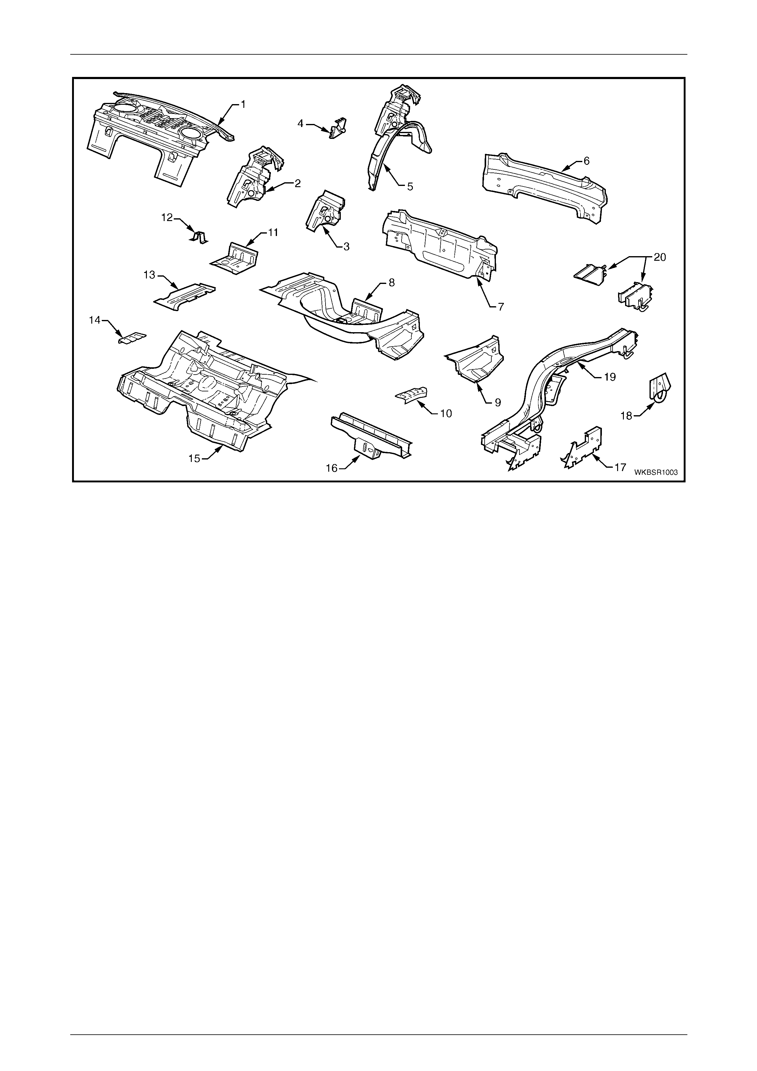
Figure 10 – 2
Legend
1 Rear Window Panel Assembly
2 Rear Seat Back Panel Extension Assembly
3 Rear Seat Back Panel Extension
4 Rear Compartment Lid Strut Bracket Assembly
5 Rear Wheelhouse Panel Assembly
6 Rear End Lower Panel
7 Rear End Panel Assembly
8 Rear Compartment Floor Panel Assembly
9 Rear Compartment Floor Panel Outer Extension, Left-hand
10 Rear Floor Panel Reinforcement, Left-hand
11 Fuel Tank Support Reinforcement Assembly
12 Spare Wheel Anchor Plate Assembly
13 Rear Compartment Floor Panel Outer Extension,
Right-hand
14 Rear Floor Panel Reinforcement, Right-hand
15 Rear Floor Panel Assembly
16 Crossmember Assembly No. 2
17 Rear Floor Panel Outer Extension
18 Rear Tie Down Assembly
19 Rear Side Rail Assembly
20 Rear Bumper Impact Bar Brace Assembly
NOTE
• Rear wheelhouse pane l assembly (5) includes
part No. 2, which includes parts No. 3 and 4.
• Rear compartment floor panel assembly (8)
includes parts No. 9, 10, 11, 12, 13 and 14.
• Rear side rail assembly (19) includes parts
No. 17,18, and 20.
10 Body Rear Page 10–5
Page 10–5
2 Service Operations
2.1 Rear End Lower Panel – Replace
Remove
To avoid the possibility of fire, take particular
care when cuttin g or w elding at the r ear of th e
vehicle. Remove the fuel tank and plug all fuel
lines.
NOTE
If the rear end panel assembly (inner) is also to
be replaced, remove the rear end panels as an
assembly. Refer to 2.2 Rear End Panel
Assembly – Replace.
1 Remove the adjacent bolt-on panels a nd components
as described in the appropriate Section of the MY2005
WL Service Information.
2 Remove the rear bumper impact bar assembly,
refer to Section 3 Body Construction .
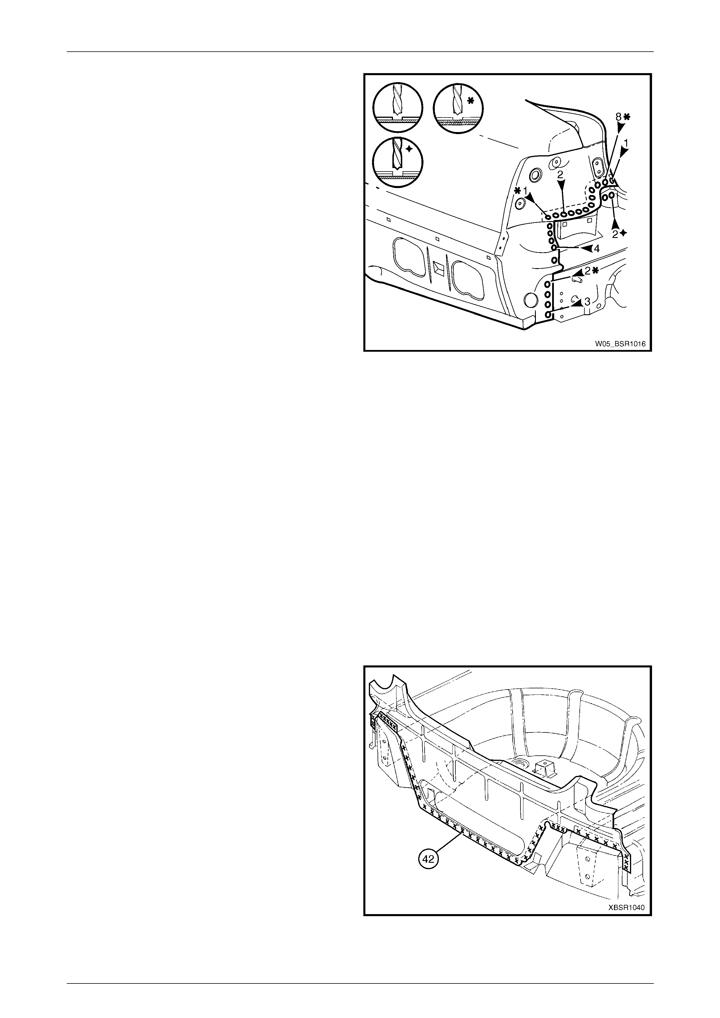
Figure 10 – 3
3 Spot cut the welds attaching the rear end lower panel
to the rear quarter panel, web plate, quarter pan el
lower extension panel and tail lamp housing.
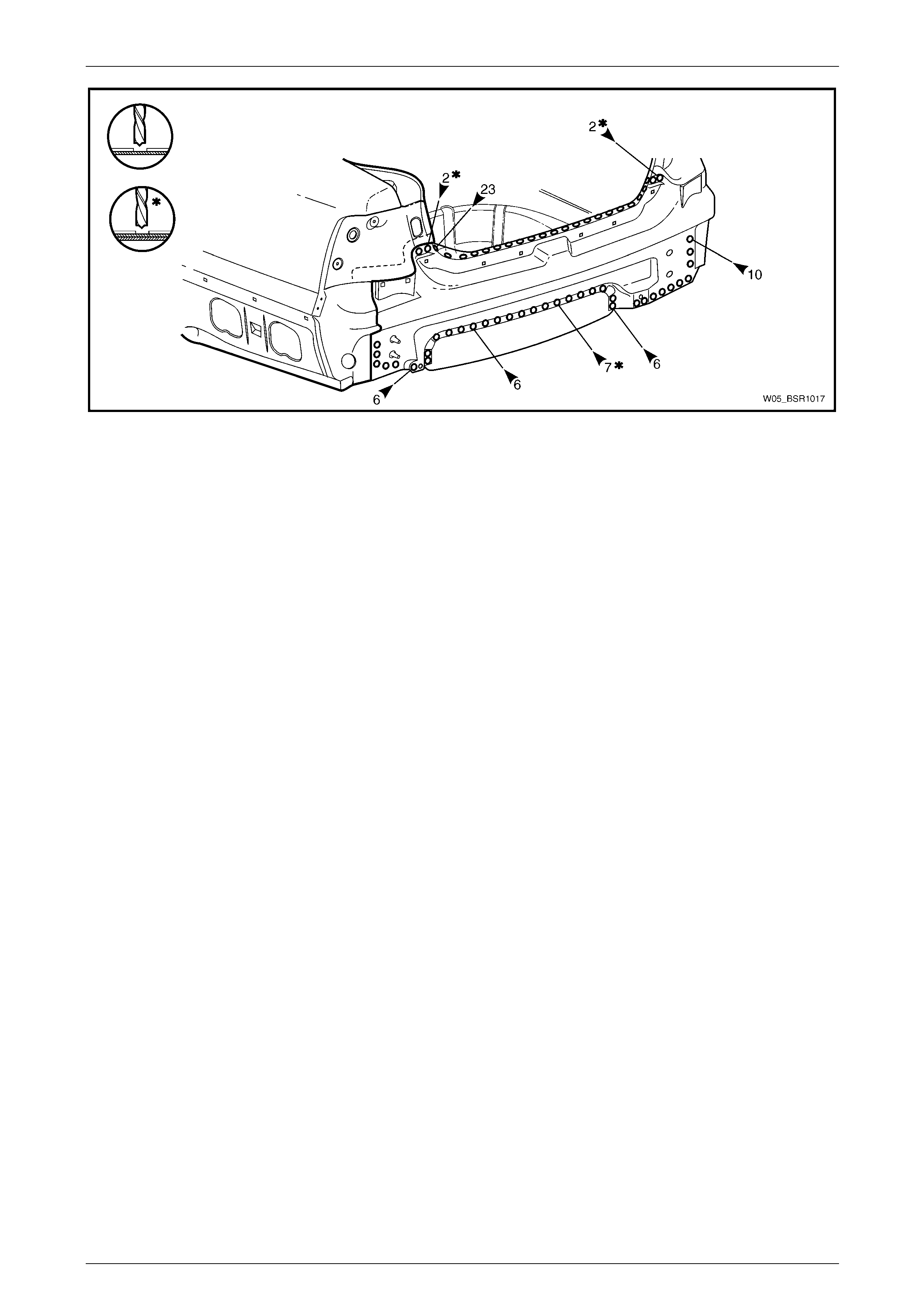
4 Spot cut the welds attaching the rear end lower panel
to the rear end panel assembly, rear quarter panel and
quarter panel lower extension, refer to Figure 10 – 5.
Figure 10 – 4
10 Body Rear Page 10–6
Page 10–6
Figure 10 – 5
5 Remove the rear end lower panel from the vehicle and repair any damage to adjac ent parts as required.
NOTE
Carefully bend the flange of the rear quarter
panel and quarter panel lower extension to allow
removal of the rear end lower panel.
Replace
NOTE
• Spot welding is the preferred method for
attaching of panels and should be used
whenever possible. Where the spot welding
equipment available will not access the
required weld position, a plug weld should be
performed.
• The same number and position of spot welds
(or plug welds) should be used when
replacing the panel, as was used during
manufacture, in order to maintain the original
structural strength of the vehicle.
1 As required, mark the new panel with drilling locations, in preparation for p lug welding. Drill holes as required.
2 Prepare all mating surfaces and treat with Weld Through Primer (Item 1) as requir ed, refer to
Section 3 Body Construction .
3 Clamp the rear end lower panel in position on the vehicle ensuring it is seated under the rear quarter panel and
quarter panel lower extension flanges.
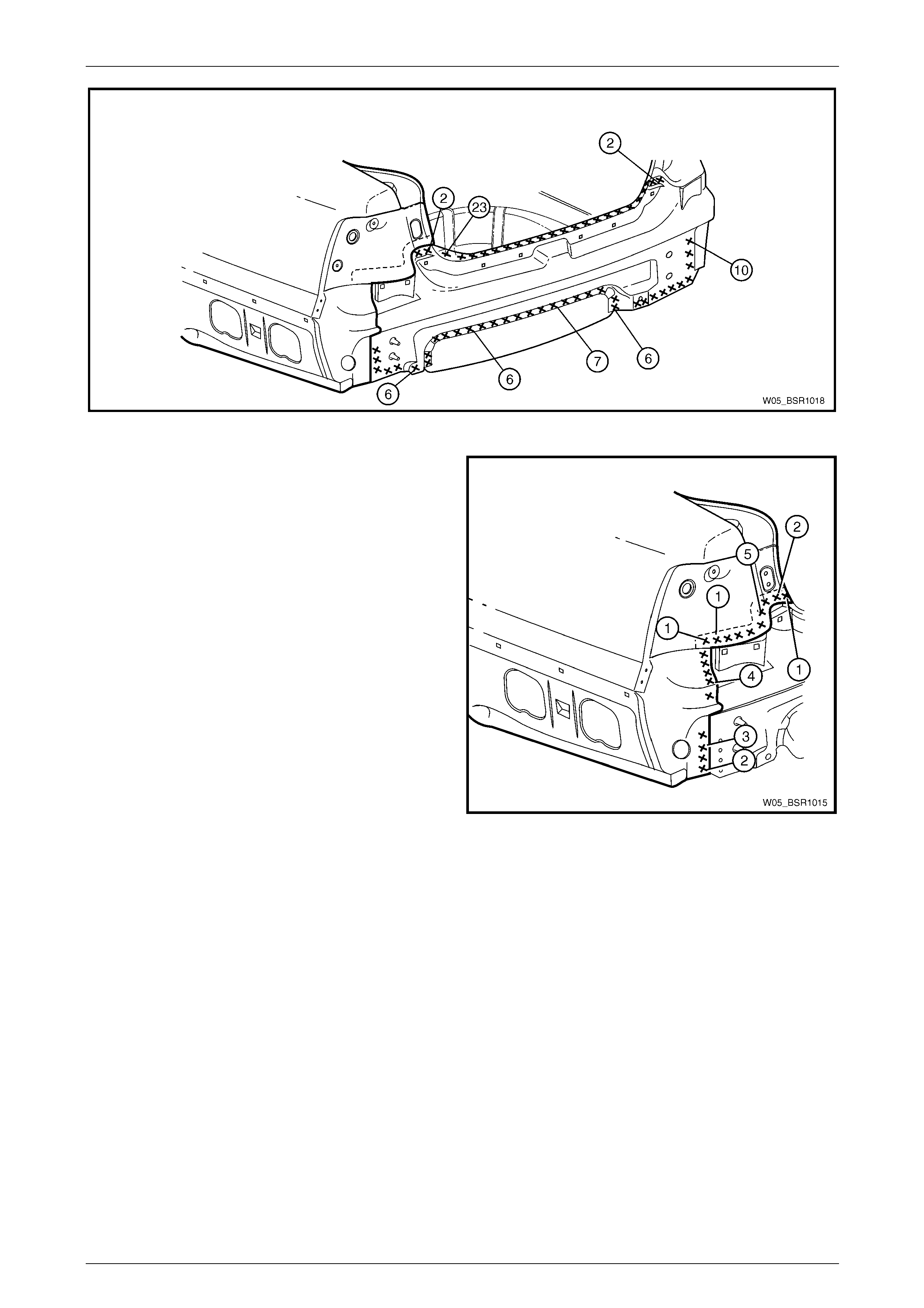
4 Spot or plug weld the rear end lo wer panel to the rear end panel assembly and rear end panel extension, refer to
Figure 10 – 6.
10 Body Rear Page 10–7
Page 10–7
Figure 10 – 6
5 Spot or plug weld the rear end lo wer panel to the tail
lamp housing.
6 Refinish and paint panels and other components as
required. Refer to Section 3 Body Construction .
7 Apply Joint Sealer (Item 3) as required.
Refer to Section 3 Body Construction .
8 Apply Cavity Wax (Item 8) as required to the inside of
any box sections or areas inaccessible to paint,
refer to Section 3 Body Construction .
9 Install the front bumper impact bar assembly, refer to
Section 3 Body Construction .
10 Install the remaining components as described in the
appropriate MY2005 WL Service Information.
Figure 10 – 7
10 Body Rear Page 10–8
Page 10–8
2.2 Rear End Panel Assembly – Replace
Remove
To avoid the possibility of fire, take particular
care when cuttin g or w elding at the r ear of th e
vehicle. Remove the fuel tank and plug all fuel
lines.
NOTE
This procedure describes the removal of the rear
end lower panel and rear end panel assembly
together. As the panels are supplied individually,
this procedure contains the replacement of the
rear end panel assembly only. Reference should
be then made to 2.1 Rear End Lower Panel –
Replace for the relevant replacement procedures
of the remaining panel.
1 Remove the adjacent bolt-on panels a nd components
as described in the appropriate Section of the MY2005
WL Service Information.
2 Remove the rear bumper impact bar assembly,
refer to Section 3 Body Construction .
Figure 10 – 8
3 Spot cut the welds attaching the fuel tank support
reinforcement (1) to the rear end pane l assembly (2).
NOTE
As an alternative, remove the fuel tank support
reinforcement from the rear compartment floor
panel assembly, refer to 2.3 Fuel Tank Support
Reinforcement Assembly – Replace..
4 Spot cut the welds attaching the rear end panel
assembly to the rear compartment floor assembly,
refer to Figure 10 – 10.
Figure 10 – 9
10 Body Rear Page 10–9
Page 10–9
Figure 10 – 10
5 Spot cut the welds attaching the rear side rail
assemblies to the rear end panel ass embl y. Note that
the left-hand side is different to the right-hand side.
Figure 10 – 11
10 Body Rear Page 10–10
Page 10–10
6 Spot cut the welds attaching the rear end panel
assembly to the rear quarter panel, rear quarter panel
lower extension, tail lamp housing and rear end panel
extension as required on each side of the vehicle.
7 Remove the panels from the vehicle then repair any
damage to adjacent parts as required.
NOTE
Carefully bend the flange of the rear quarter
panel, and quarter panel lower extension to
allow removal of the rear end panel assembly.
8 Check and rectify the alignme nt of the bod y as
required, refer to Section 3 Body Construction .
Figure 10 – 12
Replace
NOTE
• Spot welding is the preferred method for
attaching of panels and should be used
whenever possible. Where the spot welding
equipment available will not access the
required weld position, a plug weld should be
performed.
• The same number and position of spot welds
(or plug welds) should be used when
replacing the panel, as was used during
manufacture, in order to maintain the original
structural strength of the vehicle.
1 As required, mark the new panel with drilling locations, in preparation for p lug welding. Drill holes as required.
2 Prepare all mating surfaces and treat with Weld Through Primer (Item 1) as required,
refer to Section 3 Body Construction .
3 Clamp the rear end panel in p osition on the vehicle
and spot or plug weld to the rear compartment floor
panel assembly.
NOTE
If the rear quarter panel, tail lamp housing, rear
end panel extension and rear quarter panel
extension were not removed, ensure the rear
end panel is positioned behind the flange of
these panels.
Figure 10 – 13
10 Body Rear Page 10–11
Page 10–11
4 Spot or plug weld the rear end panel to the r ear side
rail assembly on each side of the vehicle. The left-
hand side is different to the right-han d side.
5 If removed, install the fuel tank support reinforcement
and weld to the rear compartment floor panel
assembly only, refer to 2.3 Fuel Tank Support
Reinforcement Assembly – Replace..
6 In the areas where the rear end lower pane l will fit,
grind the welds and prime any bare metal.
7 Install the rear end lower panel, refer to
2.1 Rear End Lower Panel – Replace.
Figure 10 – 14
8 Finish plug welding the fuel tank support reinforcement
to the rear end panel.
9 Refinish and paint panels and other components as
required. Refer to Section 3 Body Construction .
10 Apply Joint Sealer (Item 3) as required.
Refer to Section 3 Body Construction .
11 Apply Cavity Wax (Item 8) as required to the inside of
any box sections or areas inaccessible to paint,
refer to Section 3 Body Construction .
12 Install the rear bumper impact bar assembly,
refer to Section 3 Body Construction .
13 Install the remaining components as described in the
appropriate Section of the MY2005 WL Service
Information.
Figure 10 – 15
10 Body Rear Page 10–12
Page 10–12
2.3 Fuel Tank Support Reinforcement
Assembly – Replace.
Remove
To avoid the possibility of fire, take particular
care when cuttin g or w elding at the r ear of th e
vehicle. Remove the fuel tank and plug all fuel
lines.
1 Remove the adjacent bolt-on panels a nd components
as described in the appropriate Section of the MY2005
WL Service Information.
2 Remove the deadener panels and joint sealer from
around the fuel tank support reinforc ement assembly
as required.
Figure 10 – 16
3 Spot cut the 14 welds attaching the reinforcement to
the rear end panel assembly.
4 Spot cut the 14 welds attaching the reinforcement to
the rear compartment floor panel assembly.
5 Remove the fuel tank support reinforcem ent assembly
and then repair any damage t o adjacent parts as
required.
Figure 10 – 17
10 Body Rear Page 10–13
Page 10–13
Replace
NOTE
• Spot welding is the preferred method for
attaching of panels and should be used
whenever possible. Where the spot welding
equipment available will not access the
required weld position, a plug weld should be
performed.
• The same number and position of spot welds
(or plug welds) should be used when
replacing the panel, as was used during
manufacture, in order to maintain the original
structural strength of the vehicle.
1 As required, mark the new panel with drilling locations, in preparation for p lug welding. Drill holes as required.
2 Prepare all mating surfaces and treat with Weld Through Primer (Item 1) as required,
refer to Section 3 Body Construction .
3 Plug weld the fuel tank support reinforceme nt to the
rear compartment floor panel and rear end panel
assembly.
4 Refinish and paint panels and other components as
required. Refer to Section 3 Body Construction .
5 Apply Joint Sealer (Item 3) as required.
Refer to Section 3 Body Construction .
6 Apply Cavity Wax (Item 8) as required to the inside of
any box sections or areas inaccessible to paint,
refer to Section 3 Body Construction .
7 Install the deadener panels as required,
refer to Section 3 Body Construction .
8 Install the remaining components as described in the
appropriate Section of the MY2005 WL Service
Information
Figure 10 – 18
10 Body Rear Page 10–14
Page 10–14
2.4 Rear Compartment Floor Panel Outer
Extension – Replace
Remove
To avoid the possibility of fire, take particular
care when cuttin g or w elding at the r ear of th e
vehicle. Remove the fuel tank and plug all fuel
lines.
1 Remove the adjacent bolt-on panels a nd components
as described in the appropriate Section of the MY2005
WL Service Information.
2 Remove the joint sealer from around the rear
compartment floor panel outer exte nsion joins as
required.
3 Spot cut the welds attaching the rear compartment
floor panel outer extension to the rear compartment
floor panel, rear side rail asse mbly, rear quarter panel
and rear wheelhouse panel as required.
Refer to Figure 10 – 20.
NOTE
Also remove several welds from the left-hand
rear floor panel reinforcement as shown. Figure 10 – 19
4 Remove the extension from the vehicle and then repair any damage to adjacent parts as requ ired.
5 Check and rectify the alignme nt of the body as required, ref er to Section 3 Body Construction .
Figure 10 – 20
10 Body Rear Page 10–15
Page 10–15
Replace
NOTE
Spot welding is the preferred method for
attaching of panels and should be used whenever
possible. Where the spot welding equipment will
not access the required weld position, a plug
weld should be performed.
NOTE
The same number and position of spot welds (or
plug welds) should be used when replacing the
panel, as was used during manufacture, in order
to maintain the original structural strength of the
vehicle.
1 As required, mark the new panel with drilling locations in preparation for plug welding. Drill holes as required.
2 Prepare all mating surfaces and treat with Weld Through Primer (Item 1) as requir ed,
refer to Section 3 Body Construction .
3 Apply Acrylic Spot Weld Sealer (Item 2), refer to Section 3 Body Construction .
4 Fit the left-hand rear compartment floor panel outer
extension in po sition, ensuring the front edge is seated
under the rear floor panel rein forcement.
5 Spot or plug weld the extension to the rear
compartment floor panel, rear floor panel
reinforcement, rear side rail assembly, rear quarter
panel and the rear wheelhouse panel as req uired.
Figure 10 – 21
6 Fit the right-hand rear compartment floor panel outer
extension and spot or plug weld it to the rear
compartment floor panel, rear side rail assembly, rear
quarter panel and the rear wheelhouse panel as
required.
7 Replace the removed adjac en t bolt-on panels and
components as described in the appropriate Section of
the MY2005 WL Service Information.
8 Refinish and paint panels and other components as
required. Refer to Section 3 Body Construction .
9 Apply Joint Sealer (Item 3) as required.
Refer to Section 3 Body Construction .
10 Apply Cavity Wax (Item 8) as required to the inside of
any box sections or areas inaccessible to paint,
refer to Section 3 Body Construction .
11 Apply Spray-on Dea dener (Item 7) where applicab le,
refer to Section 3 Body Construction .
12 Install the remaining components as described in the
appropriate Section of the MY2005 WL Service
Information.
Figure 10 – 22
10 Body Rear Page 10–16
Page 10–16
2.5 Rear Compartment Floor Panel
Assembly – Replace
Remove
To avoid the possibility of fire, take particular
care when cuttin g or w elding at the r ear of th e
vehicle. Remove the fuel tank and plug all fuel
lines.
1 Remove the adjacent bolt-on panels a nd components
as described in the appropriate Section of the MY2005
WL Service Information.
2 Secure the vehicle on a suitable fixture and us e a
suitable brace to maintain the alignment of the rear
side rail assemblies prior to removal of the re ar end
panel assembly.
3 Remove the rear end panel assembly, refer to
2.2 Rear End Panel Assembly – Replace.
4 Remove the joint sealer from the surrounding area
using a scraper and heat gun.
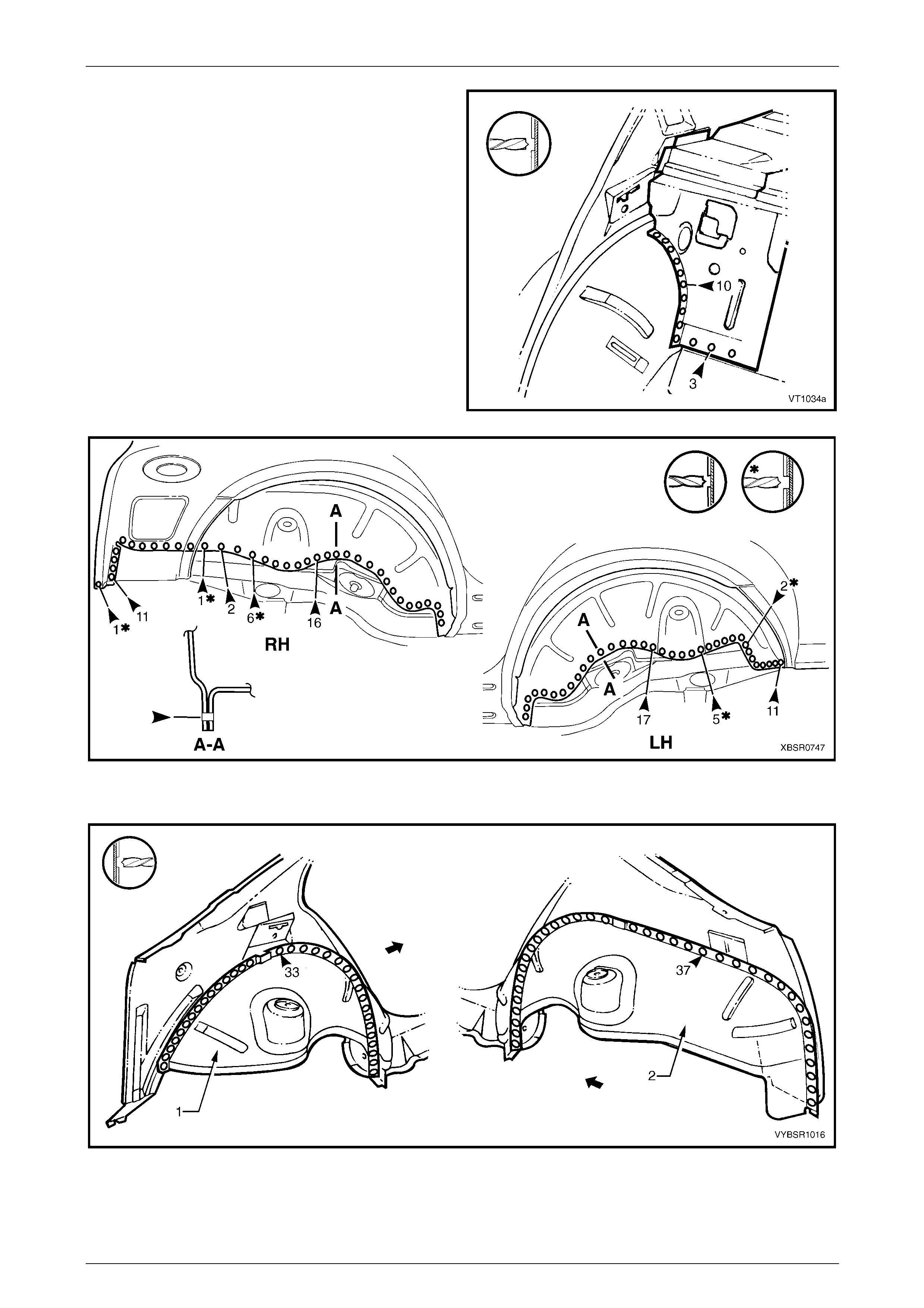
5 As required, spot cut each rear compartment floor
panel outer extension from the rear wheelho use panel
and rear quarter panel, refer to Figure 10 – 24. Figure 10 – 23
Figure 10 – 24
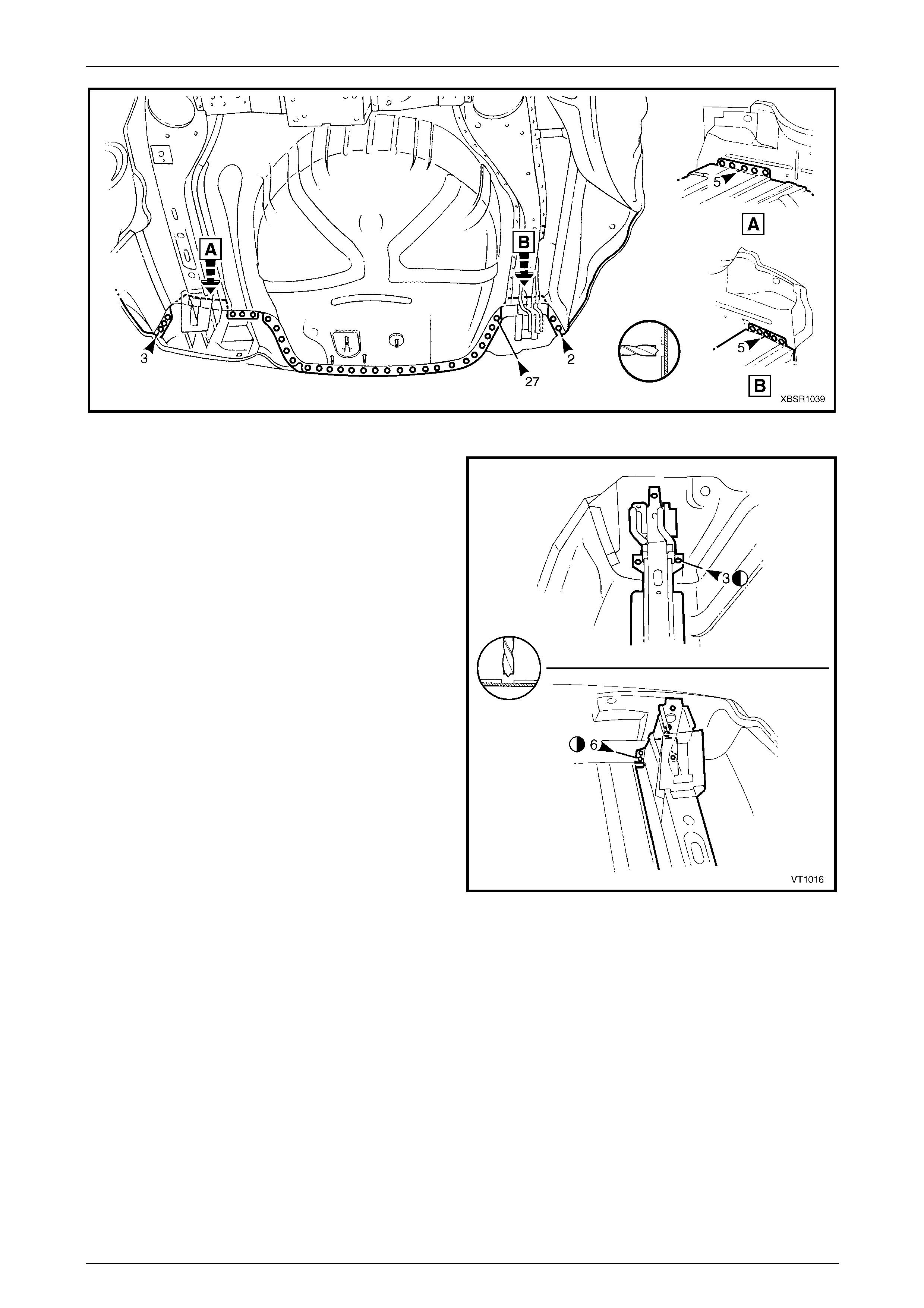
6 Spot cut the welds attaching the rear compartment floor panel assem bly (1) to the rear floor panel assembly (2) and
to the rear side rail assemblies, refer to Figure 10 – 25.
10 Body Rear Page 10–17
Page 10–17
NOTE
Structural adhesive is applied in the area shown
(3), refer to Section 3 Body Construction .
Figure 10 – 25
7 Remove the rear compartment floor pane l assembly from the vehicle and repair any damage to adjacent parts as
required.
8 Check and rectify the alignme nt of the body as required, refer to Section 3 Body Construction .
Replace
NOTE
• Spot welding is the preferred method for
attaching of panels and should be used
whenever possible. Where the spot welding
equipment will not access the required weld
position, a plug weld should be performed.
• The same number and position of spot welds
(or plug welds) should be used when
replacing the panel, as was used during
manufacture, in order to maintain the original
structural strength of the vehicle.
1 As required, mark the new panel with drilling locations in preparation for plug welding. Drill holes as required.
2 Prepare all mating surfaces and treat with Weld Through Primer (Item 1) as requir ed,
refer to Section 3 Body Construction .
3 Apply Acrylic Spot Weld Sealer (Item 2), refer to Section 3 Body Construction .
4 Apply Structural Adhesive (Item 6), refer to Section 3 Body Construction .
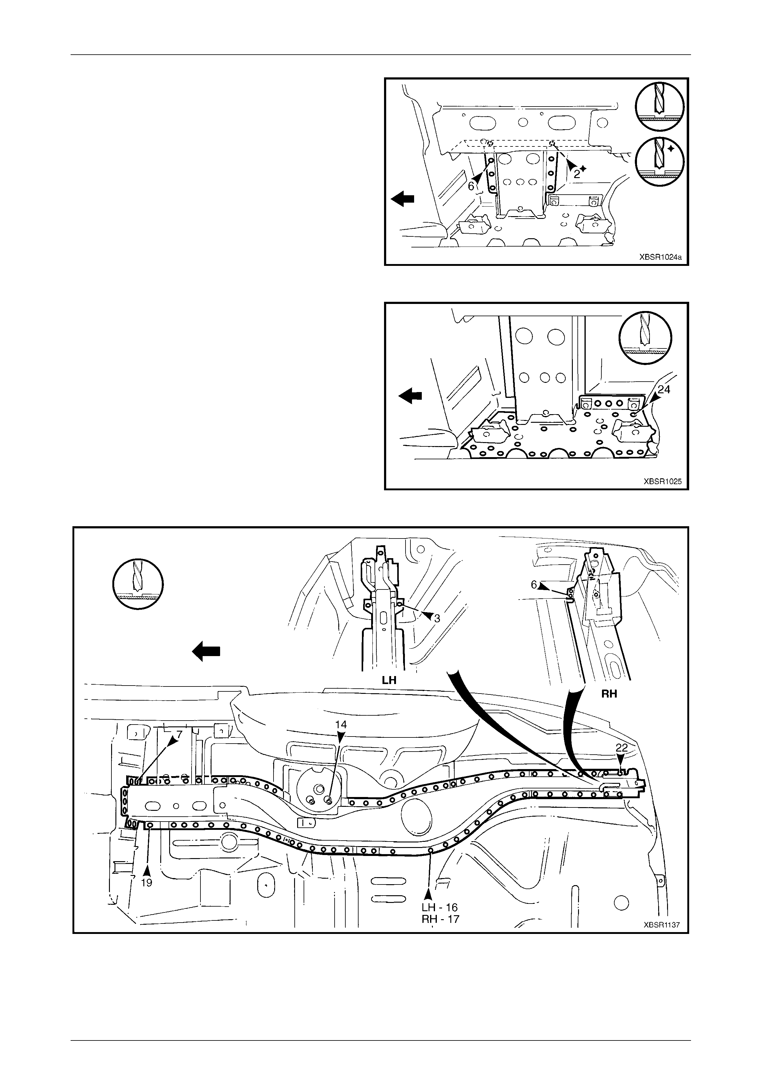
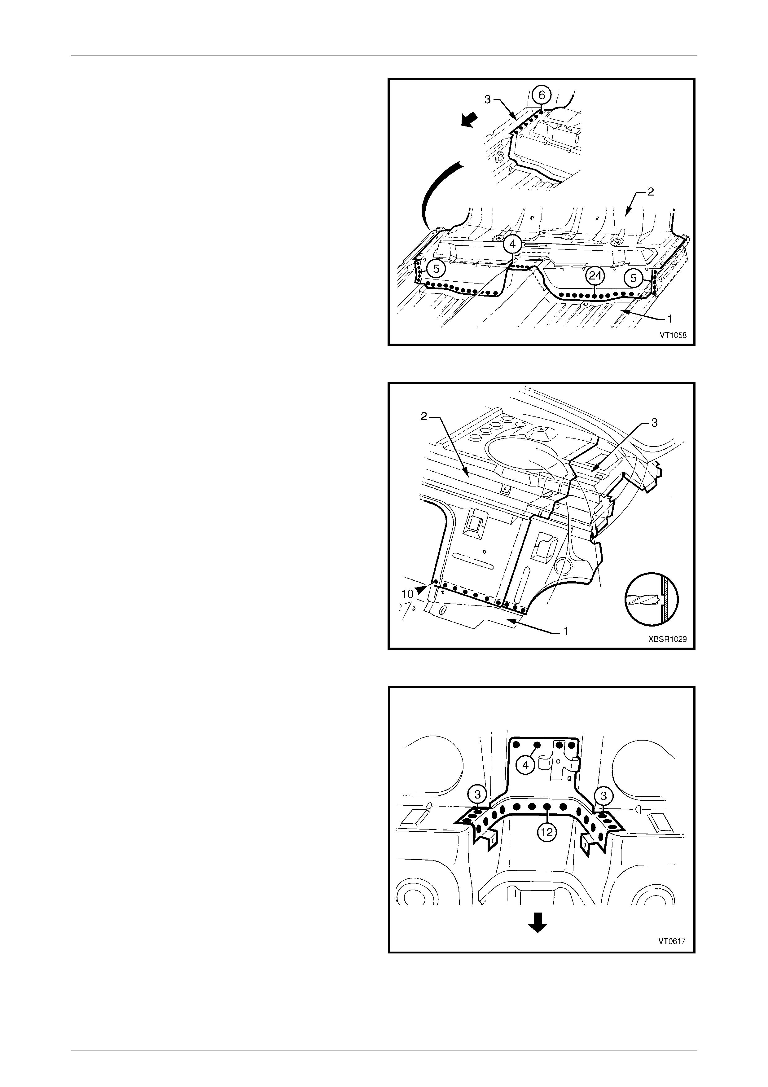
5 Install the rear compartment floor panel assembly (1) ensuring it is seated under the left-hand rear floor p anel
reinforcement.
6 Plug weld along the join of the rear floor pan el assembly (2) and to the rear side rail assemblies,
refer to Figure 10 – 26.

10 Body Rear Page 10–18
Page 10–18
Figure 10 – 26
7 As required, spot or plug weld each rear compartment floor panel outer extension to the rear wheelhouse panel,
rear quarter panel, rear end panel assembly and for the left-hand side, the rear floor panel reinforcement, refer to
Figure 10 – 27.
Figure 10 – 27
8 Install the rear end panel and other panels as requir ed, refer to the appropriate Section of the MY2005 WL Service
Information.
9 Refinish and paint panels and other components as required. Refer to Section 3 Body Construction .
10 Apply Joint Sealer (Item 3) as required. Refer to Section 3 Body Construction .
11 Apply deadener panels to the rear compartment floor panel, refer to Section 3 Body Construction .
12 Apply Cavity Wax (Item 8) as required to the inside of any box secti ons or areas inaccessible to paint,
refer to Section 3 Body Construction .
13 Apply Spray-on Dea dener (Item 7) where applicab le, refer to Section 3 Body Construction .
14 Install the remaining components as described in the appr opriate Section of the MY2005 WL Service Information.
10 Body Rear Page 10–19
Page 10–19
2.6 Rear Window Panel Assembly – Replace
Remove
To avoid the possibility of fire, take particular
care when cuttin g or w elding at the r ear of th e
vehicle. Remove the fuel tank and plug all fuel
lines.
NOTE
Depending on the area of damage, it may be
advisable to includ e removal of the rear seat back
panel extension assembly or rear wheelhouse
inner panel assembly. Refer to 2.7 Rear Seat
Back Panel Extension Assembly or Rear
Wheelhouse Inner Pan el Asse mbly – Replace.
1 Remove the adjacent bolt-on panels a nd components
as described in the appropriate Section of the MY2005
WL Service Information.
2 Remove the rear seat back panel centre extension,
refer to Section 3 Body Construction .
Figure 10 – 28
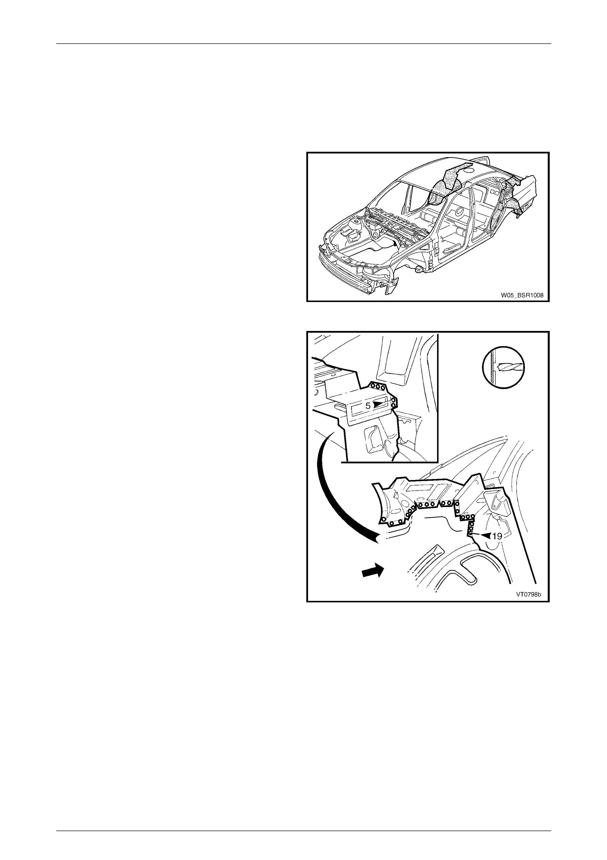
3 Remove the spot welds attaching the rear window
panel assembly (1) to the rear seat back panel
extension asse mbly (2) and the rear floor panel
assembly (3).
Figure 10 – 29

10 Body Rear Page 10–20
Page 10–20
The rear window panel assembly (1) is
attached to the rear seat back panel
extension assembly (2) and rear quarter
panel with spot welding and structural
adhesive (shown shaded). The adhesive
bond is not breakable by any normal means,
so spot cutting is not a viable method of
removal of the panel.
4 Cut the rear window panel assembl y i nboard of the
join to the rear seat back panel extension assembly
with a grinder or other cutting tool along line (3).
5 Remove the rear window panel assembly from the
vehicle.
Figure 10 – 30
6 Using a grinder, remove the remaining portion of the
rear window panel assembly and the layer of adhesive
below it as required.
7 Repair any damage to adjacent parts as required.
8 Check and rectify the alignme nt of the bod y as
required, refer to Section 3 Body Construction
Figure 10 – 31
Replace
NOTE
• Spot welding is the preferred method for
attaching of panels and should be used
whenever possible. Where the spot welding
equipment will not access the required weld
position, a plug weld should be performed.
• The same number and position of spot welds
(or plug welds) should be used when
replacing the panel, as was used during
manufacture, in order to maintain the original
structural strength of the vehicle.
1 As required, mark the new panel with drilling locations, in preparation for p lug welding. Drill holes as required.
2 Prepare all mating surfaces and treat with Weld Through Primer (Item 1) as required,
refer to Section 3 Body Construction .
10 Body Rear Page 10–21
Page 10–21
3 Apply Structural adhesive (Item 6) to the areas shown,
refer to Section 3 Body Construction .
4 Clamp the rear windo w panel assemb ly in position on
the vehicle.
Figure 10 – 32
6 Spot or plug weld the rear windo w panel assembly (1)
to the rear seat back extension panel assembly (2).
7 Refinish and paint panels and other components as
required. Refer to Section 3 Body Construction .
8 Apply Joint Sealer (Item 3) as required.
Refer to Section 3 Body Construction .
9 Apply Cavity Wax (Item 8) as required to the inside of
any box sections or areas inaccessible to paint,
refer to Section 3 Body Construction .
10 Install the remaining components as described in the
appropriate Section of the MY2005 WL Service
Information. Figure 10 – 33
10 Body Rear Page 10–22
Page 10–22
2.7 Rear Seat Back Panel Extension
Assembly or Rear Wheelhouse Inner
Panel Assembly – Replace
Remove
1 Remove the adjacent bolt-on panels a nd components
as described in the appropriate Section of the MY2005
WL Service Information.
2 Either remove, or detach the rear windo w panel
assembly from the rear seat back panel extension
assembly, refer to 2.6 Rear Window Panel Assembly
– Replace.
Figure 10 – 34
3 Spot cut the welds attaching the rear seat back panel
extension asse mbly to the quarter panel inner
assembly.
Figure 10 – 35
10 Body Rear Page 10–23
Page 10–23
4 Spot cut the three welds attaching the rear seat back
panel extension assembly to the rear flo or pa nel
assembly.
5 If the rear seat back panel extension assembl y is to be
replaced without the rear wheelhouse inner panel,
spot cut the ten welds attaching the extension
assembly to the rear wheelhouse inner p anel
assembly.
6 Remove the rear seat back panel extens ion assembly,
if it is being replaced without the rear wheelhouse
inner panel assembly.
7 If the rear wheelhouse inner panel assembly is being
replaced, spot cut the welds attaching it to the rear
floor panel assembly and rear compartment floor panel
outer extension as required, refer to Figure 10 – 37.
Figure 10 – 36
Figure 10 – 37
8 Spot cut the welds attaching the rear wheelhouse inn er panel assembly to the quarter panel inner assembly,
refer to Figure 10 – 38.
Figure 10 – 38
9 Remove the rear wheelhouse inner panel assembly.
10 Repair any damage to adjacent parts as required.
11 Check and rectify the alignme nt of the body as required, refer to Section 3 Body Construction .
10 Body Rear Page 10–24
Page 10–24
Replace
NOTE
• Spot welding is the preferred method for
attaching of panels and should be used
whenever possible. Where the spot welding
equipment will not access the required weld
position, a plug weld should be performed.
• The same number and position of spot welds
(or plug welds) should be used when
replacing the panel, as was used during
manufacture, in order to maintain the original
structural strength of the vehicle.
1 As required, mark the new panel with drilling locations, in preparation for p lug welding. Drill holes as required.
2 Prepare all mating surfaces and treat with Weld Through Primer (Item 1) as required,
refer to Section 3 Body Construction .
3 If the rear wheelhouse inner panel assembly is being replaced, spot or plug weld around the wheelhouse inner
panel assembly to the quarter pane l inner assembly, refer to Figure 10 – 39.
Figure 10 – 39
4 Spot or plug weld the rear wheelhous e inner assembly to the rear floor panel assembly and rear comp artment floor
panel outer extension, refer to Figure 10 – 40.
Figure 10 – 40
10 Body Rear Page 10–25
Page 10–25
5 Plug weld three places, rear seat back panel extension
assembly to the rear floor panel assembly.
6 If the rear seat back panel extension assembly is
being replaced without the rear wheelhouse inner
panel, plug weld ten plac es.
Figure 10 – 41
7 Spot or plug weld the rear seat back panel extension
assembly to the quarter panel inner assembly, rear
floor panel assembly and if re quired, the rear window
panel assembly.
8 Refinish and paint panels and other components as
required. Refer to Section 3 Body Construction .
9 Apply Joint Sealer (Item 3) as required.
Refer to Section 3 Body Construction .
10 Apply Cavity Wax (Item 8) as required to the inside of
any box sections or areas inaccessible to paint,
refer to Section 3 Body Construction .
11 Install the remaining components as described in the
appropriate Section of the MY2005 WL Service
Information.
Figure 10 – 42
10 Body Rear Page 10–26
Page 10–26
2.8 Rear Compartment Lid Strut Bracket
Assembly – Replace
Remove
1 Remove the adjacent bolt-on panels and components as described in the appropriate Section of the MY2005 WL
Service Information.
2 Spot cut the welds attaching the rear compartment lid
strut bracket assembly to the rear seat back panel
extension asse mbly.
3 Remove the rear compartment lid strut bracket
assembly from the vehicle and repair any damage to
adjacent parts as required.
Figure 10 – 43
10 Body Rear Page 10–27
Page 10–27
Replace
NOTE
• Spot welding is the preferred method for
attaching of panels and should be used
whenever possible. Where the spot welding
equipment will not access the required weld
position, a plug weld should be performed.
• The same number and position of spot welds
(or plug welds) should be used when
replacing the panel, as was used during
manufacture, in order to maintain the original
structural strength of the vehicle.
1 As required, mark the new panel with drilling locations, in preparation for p lug welding. Drill holes as required.
2 Prepare all mating surfaces and treat with Weld Through Primer (Item 1) as required,
refer to Section 3 Body Construction .
3 Install the rear compartment lid strut bracket
assembly, positioning it approximatel y 12 mm from the
edge of the rear seat back panel extension assembly.
4 Plug weld the bracket assembly to the rear seat back
panel extension assembly.
5 Refinish and paint panels and other components as
required. Refer to Section 3 Body Construction .
6 Apply Cavity Wax (Item 8) as required to the inside of
any box sections or areas inaccessible to paint,
refer to Section 3 Body Construction .
7 Install the remaining components as described in the
appropriate Section of the MY2005 WL Service
Information.
Figure 10 – 44
10 Body Rear Page 10–28
Page 10–28
2.9 Crossmember Assembly No. 2 – Replace
Remove
To avoid the possibility of fire, take particular
care when cuttin g or w elding at the r ear of th e
vehicle. Remove the fuel tank and plug all fuel
lines.
1 Remove the adjacent components as described in the
appropriate Section of the MY2005 WL Service
Information.
2 Secure the vehicle on a suitable fixture. As a
minimum, support the appropriate structural s ections
of the vehicle on safety stands.
Figure 10 – 45
3 Spot cut the welds attaching the crossmember No.2 to
the crossmember bracket and to the rear side rai l, on
each side of the vehicle.
NOTE
Take care not to damage the crossmember
brackets when removing the crossmember, as
these parts are only serviced as part of the rear
side rail assemblies.
Figure 10 – 46
4 Spot cut the welds attaching the crossmember to the
rear compartment floor panel assembly.
5 Remove the crossmember from the vehicle, and then
repair any damage to adjacent parts as required.
6 Check and rectify the alignme nt of the bod y as
required, refer to Section 3 Body Construction .
Figure 10 – 47
10 Body Rear Page 10–29
Page 10–29
Replace
NOTE
• Spot welding is the preferred method for
attaching of panels and should be used
whenever possible. Where the spot welding
equipment will not access the required weld
position, a plug weld should be performed.
• The same number and position of spot welds
(or plug welds) should be used when
replacing the panel, as was used during
manufacture, in order to maintain the original
structural strength of the vehicle.
1 As required, mark the new panel with drilling locations, in preparation for p lug welding. Drill holes as required.
2 Prepare all mating surfaces and treat with Weld Through Primer (Item 1) as required,
refer to Section 3 Body Construction .
3 Plug weld the crossmember to the crossmember
bracket and rear side rail, on each si de of the vehicle.
Figure 10 – 48
4 Plug weld the crossmember to the rear compartment
floor panel assembly.
5 Refinish and paint panels and other components as
required. Refer to Section 3 Body Construction .
6 Apply Joint Sealer (Item 3) as required.
Refer to Section 3 Body Construction .
7 Apply Cavity Wax (Item 8) as required to the inside of
any box sections or areas inaccessible to paint,
refer to Section 3 Body Construction .
8 Apply Spray-on Dea dener (Item 7) where applicab le,
refer to Section 3 Body Construction .
9 Install the remaining components as described in the
appropriate Section of the MY2005 WL Service
Information.
Figure 10 – 49
10 Body Rear Page 10–30
Page 10–30
2.10 Rear Floor Panel Outer Extension –
Replace
Remove
1 Remove the adjacent components as described in the
appropriate Section of the MY2005 WL Service
Information.
Figure 10 – 50
2 Spot cut the welds attaching the rear floor panel outer
extension to the inner rocker panel and rear side rail
assembly and remove.
Figure 10 – 51
10 Body Rear Page 10–31
Page 10–31
Replace
NOTE
• Spot welding is the preferred method for
attaching of panels and should be used
whenever possible. Where the spot welding
equipment will not access the required weld
position, a plug weld should be performed.
• The same number and position of spot welds
(or plug welds) should be used when
replacing the panel, as was used during
manufacture, in order to maintain the original
structural strength of the vehicle.
1 As required, mark the new panel with drilling locations, in preparation for p lug welding. Drill holes as required.
2 Prepare all mating surfaces and treat with Weld Through Primer (Item 1) as required,
refer to Section 3 Body Construction .
3 Install and plug weld the rear floor pane l outer
extension to the inner rocker panel and rear side rail
assembly.
4 Refinish and paint panels and other components as
required. Refer to Section 3 Body Construction .
5 Apply Cavity Wax (Item 8) as required to the inside of
any box sections or areas inaccessible to paint,
refer to Section 3 Body Construction .
6 Install the remaining components as described in the
appropriate Section of the MY2005 WL Service
Information.
Figure 10 – 52
10 Body Rear Page 10–32
Page 10–32
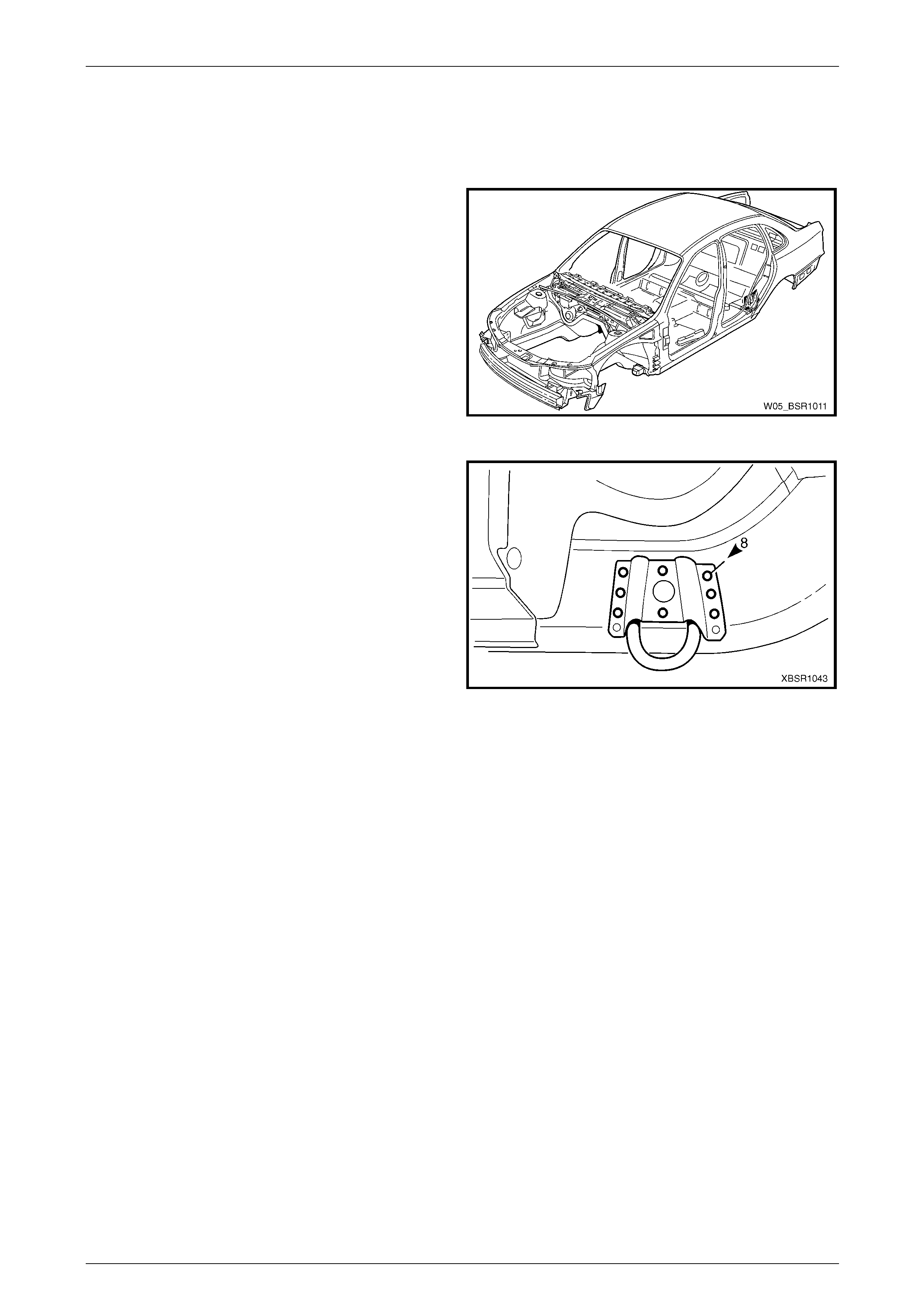
2.11 Rear Tie Down Assembly – Replace
Remove
1 Remove the adjacent components as described in the
appropriate Section of the MY2005 WL Service
Information.
Figure 10 – 53
2 Spot cut the welds attaching the tie down hook
assembly to the rear side rail assembly and remove.
Figure 10 – 54
10 Body Rear Page 10–33
Page 10–33
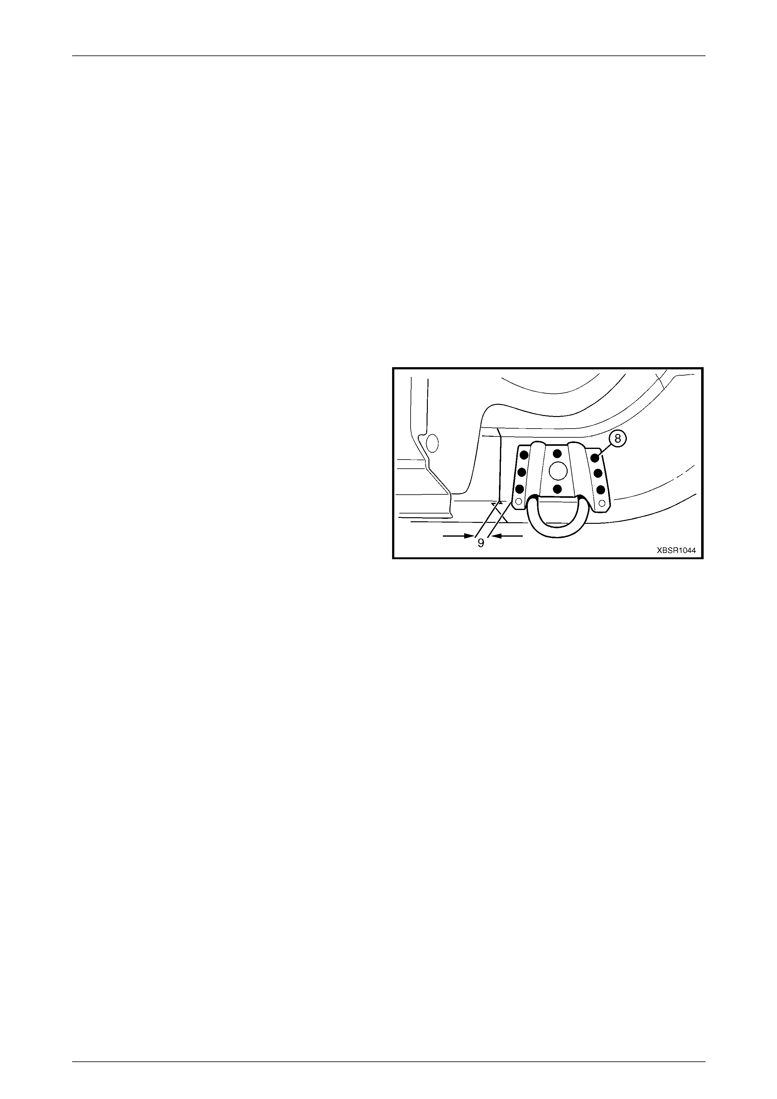
Replace
NOTE
• Spot welding is the preferred method for
attaching of panels and should be used
whenever possible. Where the spot welding
equipment will not access the required weld
position, a plug weld should be performed.
• The same number and position of spot welds
(or plug welds) should be used when
replacing the panel, as was used during
manufacture, in order to maintain the original
structural strength of the vehicle.
1 As required, mark the new panel with drilling locations, in preparation for p lug welding. Drill holes as required.
2 Prepare all mating surfaces and treat with Weld Through Primer (Item 1) as required,
refer to Section 3 Body Construction .
3 Install the tie down hook assembly onto the r ear side
rail assembly, approximately 9 mm rearward of the
join.
4 Plug weld the tie down hook assembl y to the rear side
rail assembly, eight places.
5 Refinish and paint panels and other components as
required. Refer to Section 3 Body Construction .
6 Apply Cavity Wax (Item 8) as required to the inside of
any box sections or areas inaccessible to paint,
refer to Section 3 Body Construction .
7 Install the remaining components as described in the
appropriate Section of the MY2005 WL Service
Information. Figure 10 – 55
10 Body Rear Page 10–34
Page 10–34
2.12 Rear Bumper Impact Bar Brace
Assembly – Replace
Remove
To avoid the possibility of fire, take particular
care when cuttin g or w elding at the r ear of th e
vehicle. Remove the fuel tank and plug the
fuel lines.
1 Remove the adjacent bolt-on panels a nd components
as described in the appropriate Section of the MY2005
WL Service Information.
2 Secure the vehicle on a suitable fixture. As a
minimum, support the appropriate structural s ections
of the vehicle on safety stands. Ensure that the stands
are clear of the sections being removed.
3 Remove the adjoining panels as required, refer to the
appropriate Section of this Supplement.
4 Spot cut the welds attaching the left-hand (1) or Right-
hand (2) rear bumper impact bar brace asse mbly to
the rear side rail assembly (3), refer to Figure 10 – 57.
5 If required, for the right-hand rear bumper impact bar
brace assembly, remove the closing plate (4). Figure 10 – 56
Figure 10 – 57
10 Body Rear Page 10–35
Page 10–35
Replace
NOTE
• Spot welding is the preferred method for
attaching of panels and should be used
whenever possible. Where the spot welding
equipment will not access the required weld
position, a plug weld should be performed.
• The same number and position of spot welds
(or plug welds) should be used when
replacing the panel, as was used during
manufacture, in order to maintain the original
structural strength of the vehicle.
1 As required, mark the new panel with drilling locations, in preparation for p lug welding. Drill holes as required.
2 Prepare all mating surfaces and treat with Weld Through Primer (Item 1) as required,
refer to Section 3 Body Construction .
3 Clamp and plug weld the rear bumper impact bar brace assembly (1 or 2) in position o n the rear sid e rail assembly
(3).
4 If required, for the right-hand side clamp and plug weld the closing plate (4) in position, refer to Figure 10 – 58.
Figure 10 – 58
5 Install other panels as require d, refer to the appropriate Section in this Sup plement.
6 Refinish and paint panels and other components as required. Refer to Section 3 Body Construction .
7 Apply Joint Sealer (Item 3) as required. Refer to Section 3 Body Construction .
8 Apply Cavity Wax (Item 8) as required to the inside of any box secti ons or areas inaccessible to paint,
refer to Section 3 Body Construction .
9 Install the remaining components as described in the appropriate Section of the MY2005 WL Service Informatio n.
10 Body Rear Page 10–36
Page 10–36
2.13 Rear Side Rail Assembly – Replace
Remove
To avoid the possibility of fire, take particular
care when cuttin g or w elding at the r ear of th e
vehicle. Remove the fuel tank and plug all fuel
lines.
1 Remove the adjacent bolt-on panels a nd components
as described in the appropriate Section of the MY2005
WL Service Information.
2 Secure the vehicle on a suitable fixture. As a
minimum, support the appropriate structural s ections
of the vehicle on safety stands. Ensure that the stands
are clear of the rear side rail assembly(s) being
removed.
Figure 10 – 59
3 Spot cut the welds attaching the crossmember No.2 to
the crossmember bracket and to the rear side rai l, on
each side of the vehicle.
Figure 10 – 60
4 Spot cut the welds attaching the rear side rail
assembly to the rear floor panel assembly.
Figure 10 – 61
10 Body Rear Page 10–37
Page 10–37
5 Spot cut the welds attaching the rear side rail
assembly to the rear floor panel assembly.
Figure 10 – 62
6 Spot cut the welds attaching the rear floor panel outer
extension to the inner rocker panel assembly.
7 Spot cut the rear side rail assembly from the rear floor
panel assembly, rear compart ment floor panel
assembly and the rear end panel,
refer to Figure 10 – 64.
NOTE
There are a different number of welds between
the left-hand and right-hand sides.
8 Remove the rear side rail assembly from the vehicle.
Figure 10 – 63
Figure 10 – 64
9 Repair any damage to adjacent parts as required.
10 Check and rectify the alignme nt of the body as required, refer to Section 3 Body Construction .
10 Body Rear Page 10–38
Page 10–38
Replace
NOTE
• Spot welding is the preferred method for
attaching of panels and should be used
whenever possible. Where the spot welding
equipment will not access the required weld
position, a plug weld should be performed.
• The same number and position of spot welds
(or plug welds) should be used when
replacing the panel, as was used during
manufacture, in order to maintain the original
structural strength of the vehicle.
1 As required, mark the new panel with drilling locations in preparation for plug welding. Drill holes as required.
2 Prepare all mating surfaces and treat with Weld Through Primer (Item 1) as requir ed,
refer to Section 3 Body Construction .
Prior to plug welding in this region, remove
the deadener from the inside floor to remove
the risk of fire.
3 Locate and clamp the new rear side rail assembly in position and check and adjust its alignment,
refer to Section 3 Body Construction .
4 Plug weld the rear side rail assembly to the rear floor panel assembly, rear compartment floor panel assembl y and
the rear end panel, refer to Figure 10 – 65.
Figure 10 – 65
10 Body Rear Page 10–39
Page 10–39
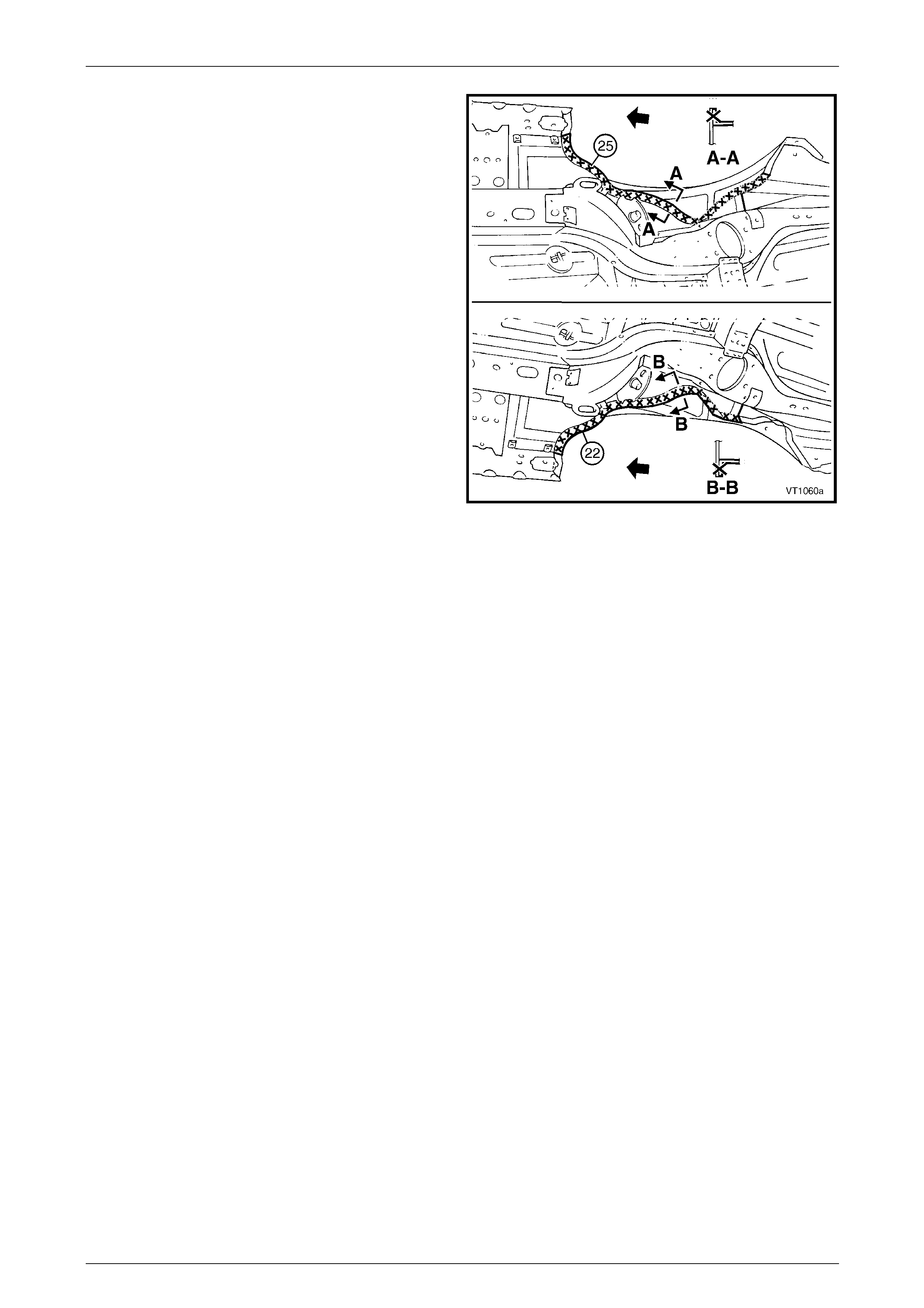
5 Plug weld the rear side rail assembly to the r ear floor
panel assembly.
Figure 10 – 66
6 Plug weld the crossmember assembly No. 2 to the
crossmember bracket and rear side rail.
Figure 10 – 67
7 Plug weld the rear side rail assembly to the r ear floor
panel assembly and the rear floor panel outer
extension to the inner rocker panel assembly.
8 Refinish and paint panels and other components as
required. Refer to Section 3 Body Construction .
9 Apply Joint Sealer (Item 3) as required.
Refer to Section 3 Body Construction .
10 Apply Cavity Wax (Item 8) as required to the inside of
any box sections or areas inaccessible to paint,
refer to Section 3 Body Construction .
11 Install the remaining components as described in the
appropriate Section of the MY2005 WL Service
Information. Figure 10 – 68
10 Body Rear Page 10–40
Page 10–40
2.14 Rear Floor Panel Assembly – Replace
Remove
To avoid the possibility of fire, take particular
care when cuttin g or w elding at the r ear of th e
vehicle. Remove the fuel tank and plug the
fuel lines.
1 Remove the adjacent bolt-on panels a nd components
as described in the appropriate Section of the MY2005
WL Service Information.
2 Secure the vehicle on a suitable fixture. As a
minimum, support the appropriate structural s ections
of the vehicle on safety stands. Ensure that the stands
are clear of the sections being removed.
3 Remove the sealer and deadener panels from the
relevant areas using a scraper and heat gun.
4 Remove the adjoining panels as required, refer to the
appropriate Section of this Supplement.
Figure 10 – 69
5 Spot cut the welds attaching the park brake cabl e
bracket to the rear floor panel assembly.
Figure 10 – 70
10 Body Rear Page 10–41
Page 10–41
6 Spot cut the welds joining the front floor panel
assembly (1) and rear floor panel assembly (2).
7 Spot cut the welds attaching the rear floor panel
assembly to the inner rocker panel (3) each side.
Figure 10 – 71
8 Spot cut the welds attaching the rear floor panel
assembly to the rear window panel assembly and the
rear seat back panel extension assembly.
Figure 10 – 72
10 Body Rear Page 10–42
Page 10–42
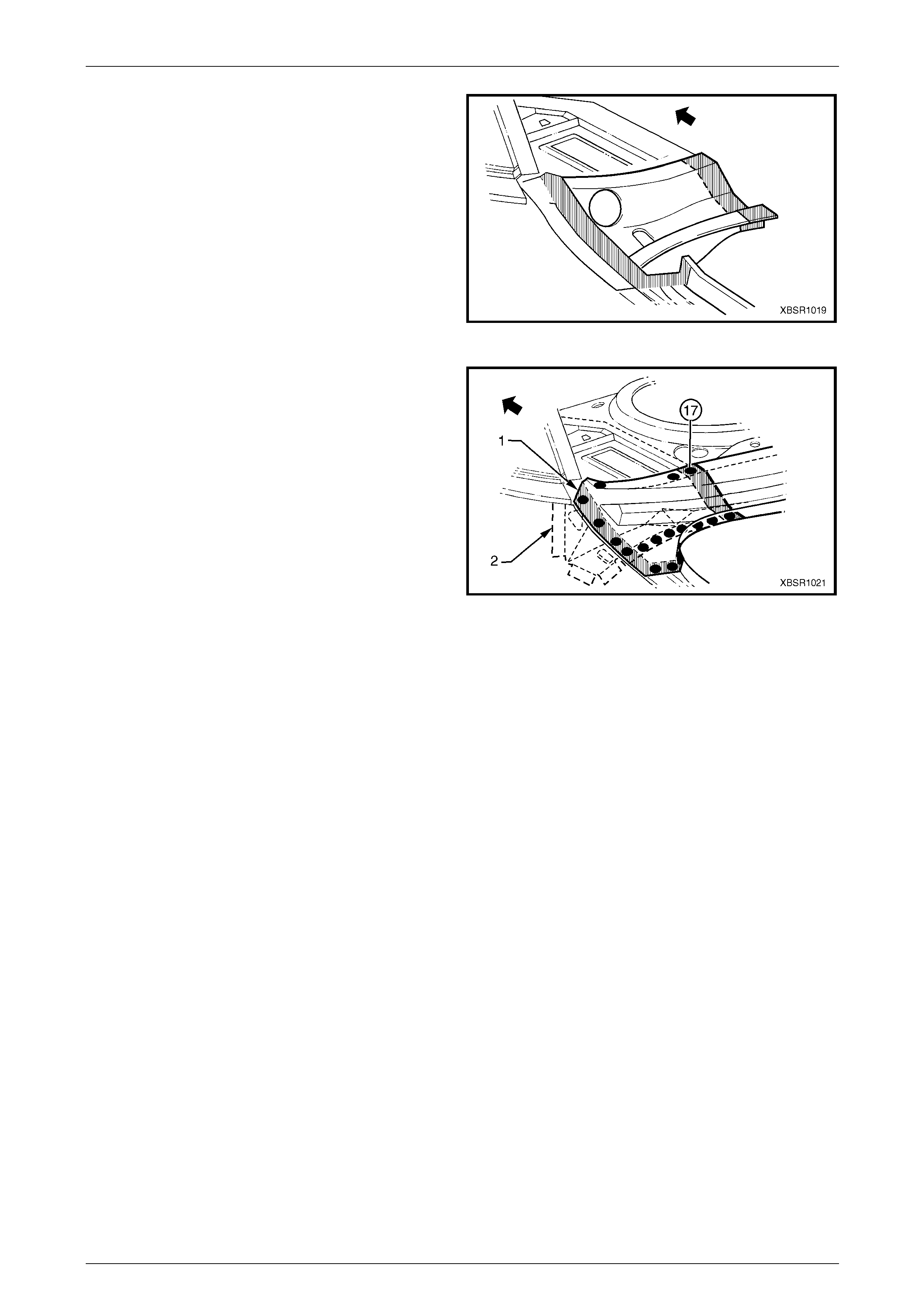
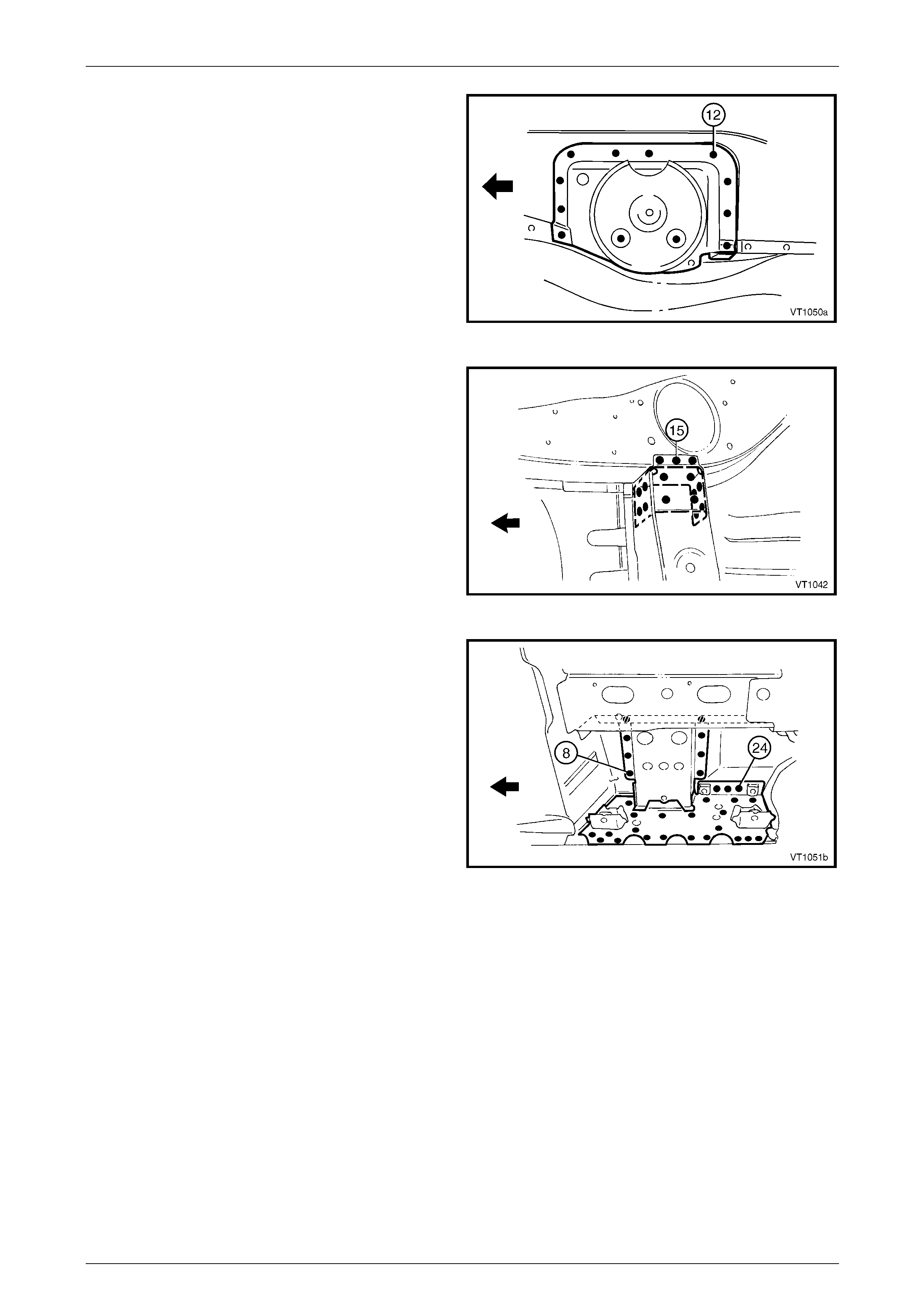
9 Spot cut the welds attaching the rear floor panel
assembly and rear floor panel reinforcement to the
rear wheelhouse inner panel assembly on each of the
vehicle.
10 Spot cut the welds attaching the crossmember
assembly No. 2 to the rear floor panel assembly, refer
to 2.9 Crossmember Assembly No. 2 – Replace.
11 Spot cut the welds attaching each rear side rail
assembly to the rear floor panel assembly,
refer to 2.13 Rear Side Rail Assembly – Replace.
12 Spot cut the welds attaching the rear floor panel
assembly and rear floor panel reinforcements to the
rear compartment floor panel assembly,
refer to Figure 10 – 74.
NOTE
• Structural adhesive is applied in
the area shown (1), refer to
Section 3 Body Construction
• Also remove the welds attaching the Left-
hand rear floor panel reinforcement to the
rear compartment floor panel outer
extension.
13 Remove the rear floor panel assembly from the vehicle
and then repair any damage t o adjacent parts as
required.
14 Check and rectify the alignme nt of the bod y as
required, refer to Section 3 Body Construction .
Figure 10 – 73
Figure 10 – 74
10 Body Rear Page 10–43
Page 10–43
Replace
NOTE
• Spot welding is the preferred method for
attaching of panels and should be used
whenever possible. Where the spot welding
equipment will not access the required weld
position, a plug weld should be performed.
• The same number and position of spot welds
(or plug welds) should be used when
replacing the panel, as was used during
manufacture, in order to maintain the original
structural strength of the vehicle.
1 As required, mark the new panel with drilling locations, in preparation for p lug welding. Drill holes as required.
2 Prepare all mating surfaces and treat with Weld Through Primer (Item 1) as required,
refer to Section 3 Body Construction .
3 Apply Structural Adhesive (Item 6), refer to Section 3 Body Construction .
4 Clamp the new panel in position in the vehicle and plug weld to the rear floor rear. Refer to Figure 10 – 75.
Figure 10 – 75
10 Body Rear Page 10–44
Page 10–44
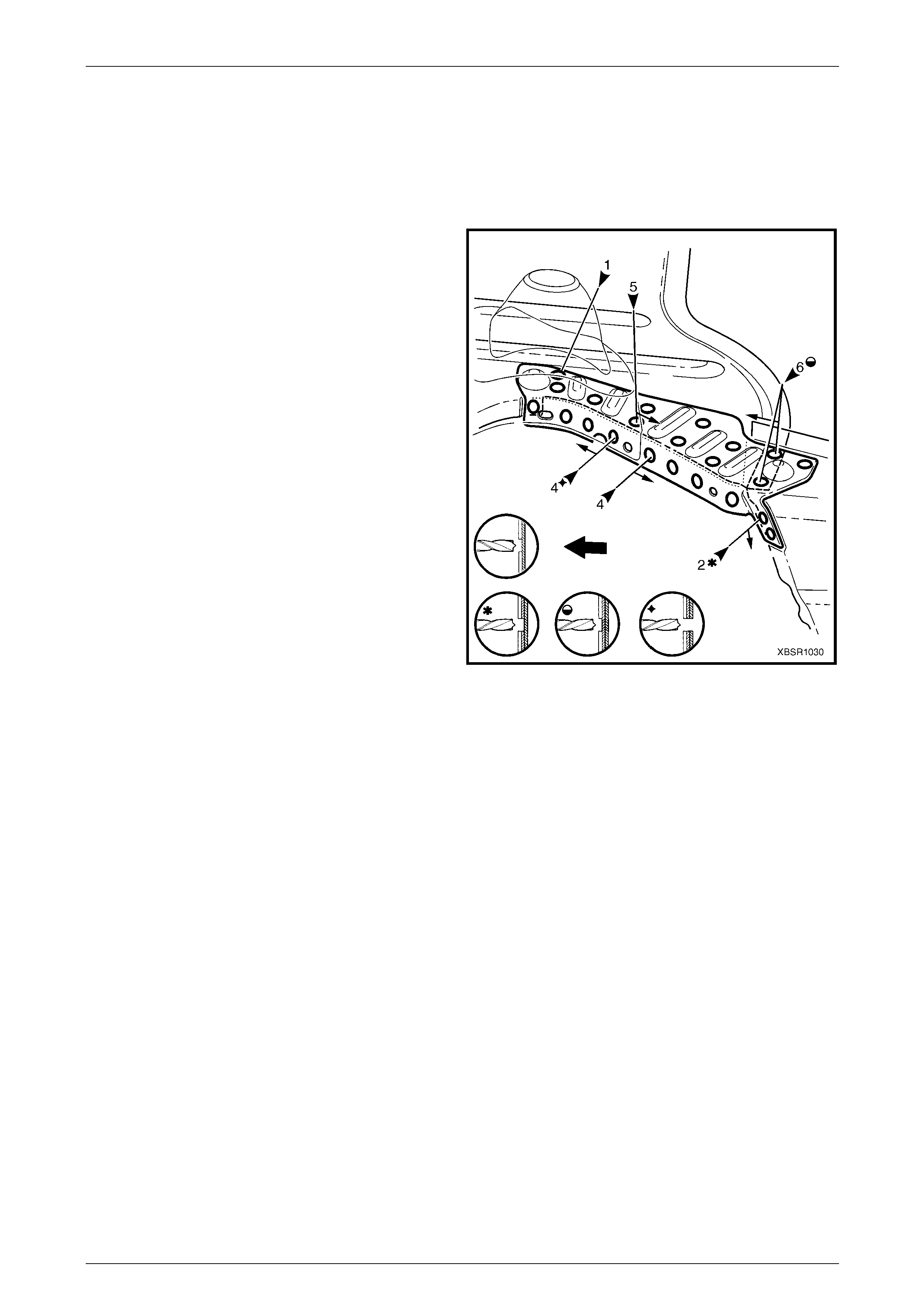
5 Plug weld the rear floor panel assembly (2) to the front
floor panel assembly (1).
6 Plug weld the rear floor panel assembly to the inner
rocker panel (3) each side.
Figure 10 – 76
7 Plug weld the rear floor panel assembly (1) to the rear
window panel assembly (2) and the rear s ea t back
panel extension assembly (3).
Figure 10 – 77
8 Plug weld the park brake cable brack et to the rear
floor panel assembly.
9 Install the rear floor panel reinforcement each side,
refer to 2.15 Rear Floor Panel Reinforcement –
Replace. Plug weld the reinf orcements on the top
surface only, completing the welds in the next step.
Figure 10 – 78
10 Body Rear Page 10–45
Page 10–45
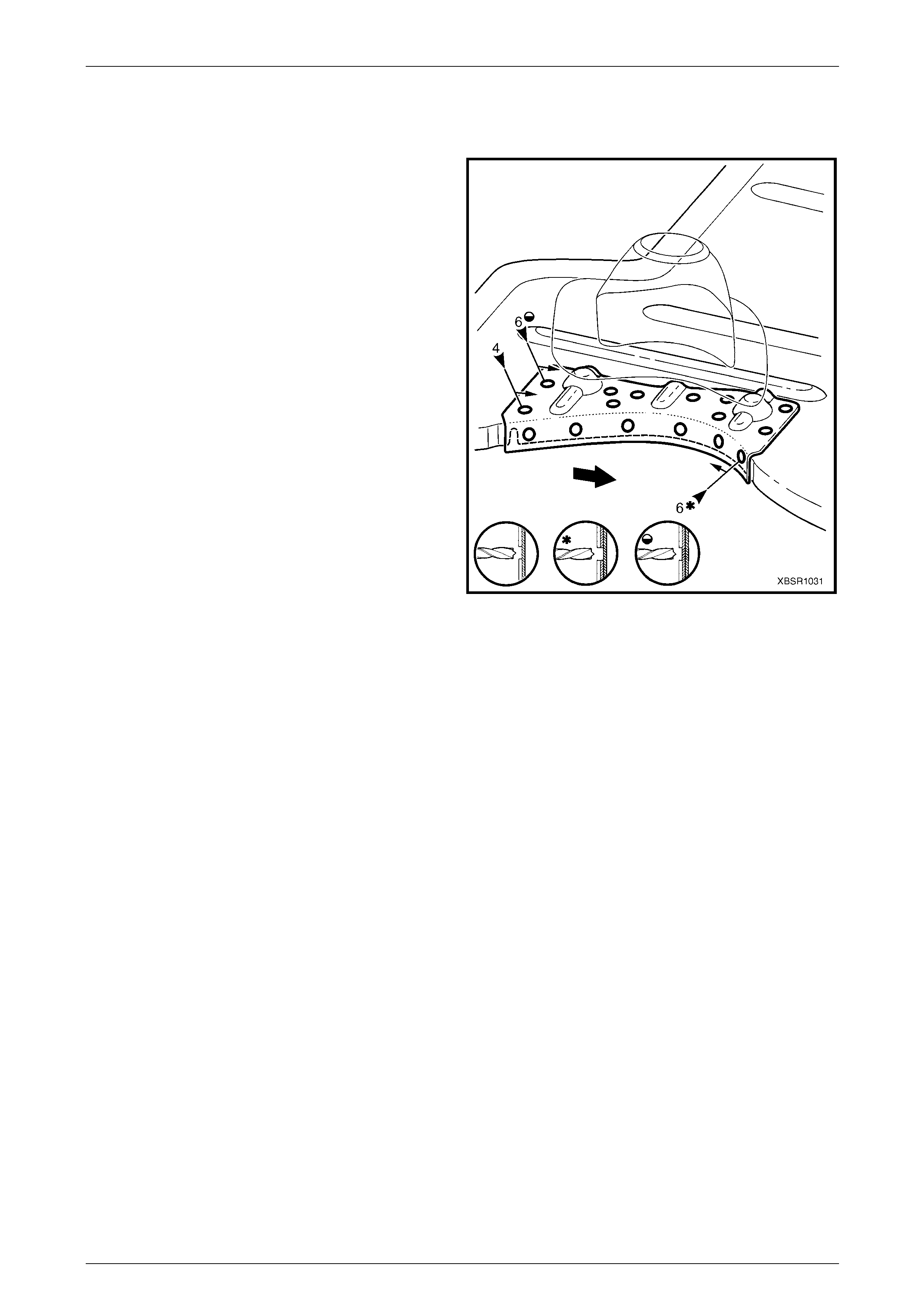
10 Spot or plug weld the rear floor panel assembly and
rear floor panel reinforcement to the rear wheelhouse
inner panel assembly on each of the vehicle.
11 Plug weld the crossmember assembly No.2 to the rear
floor panel assembly, refer to
2.9 Crossmember Assembly No. 2 – Replace.
12 Plug weld each rear side rail assembly to the rear floor
panel assembly, refer to
2.13 Rear Side Rail Assembly – Repl ace.
13 Replace any other remov ed panels as described in the
appropriate Section of this Supplement.
14 Refinish and paint panels and other components as
required. Refer to Section 3 Body Construction .
15 Apply Joint Sealer (Item 3) as required.
Refer to Section 3 Body Construction .
16 Apply Cavity Wax (Item 8) as required to the inside of
any box sections or areas inaccessible to paint,
refer to Section 3 Body Construction .
17 Apply deadener panels to the rear compartment floor
panel, refer to Section 3 Body Construction .
18 Apply Spray-on Dea dener (Item 7) where applicab le,
refer to Section 3 Body Construction .
19 Install the remaining components as described in the
appropriate Section of the MY2005 WL Service
Information.
Figure 10 – 79
10 Body Rear Page 10–46
Page 10–46
2.15 Rear Floor Panel Reinforcement –
Replace
Left-hand Side
Remove
The Left-hand rear floor panel reinforcement is spot welded
to the rear floor panel assembly, rear wheelhouse panel
assembly, rear compartment floor panel assembly outer
extension and rear side rail assembly.
As required spot cut the welds and remove the
reinforcement.
Replace
NOTE
• Spot welding is the preferred method for
attaching of panels and should be used
whenever possible. Where the spot welding
equipment available to the repairer will not
access the required weld position, a plug
weld should be performed.
• The same number a nd position of spot welds
(or plug welds) should be used when
replacing the panel, as was used during
manufacture, in order to ma intain the original
structural strength of the vehicle.
1 As required, mark the new panel with drilling locations,
in preparation for plug welding. Drill holes as required.
2 Prepare all mating surfaces and treat with Weld
Through Primer (Item 1) as required,
refer to Section 3 Body Construction .
3 Spot or plug weld the rear floor panel reinforcement to
the vehicle, ensuring it is correctly located and welded
through the correct panels.
Figure 10 – 80
10 Body Rear Page 10–47
Page 10–47
Right-hand Side
Remove
The Right-hand rear floor panel reinforceme nt is spot
welded to the rear floor panel assemb ly, rear wheelhouse
panel assembly and rear side rail assembly.
As required spot cut the welds and remove the
reinforcement.
Replace
NOTE
• Spot welding is the preferred method for
attaching of panels and should be used
whenever possible. Where the spot welding
equipment available to the repairer will not
access the required weld position, a plug
weld should be performed.
• The same number a nd position of spot welds
(or plug welds) should be used when
replacing the panel, as was used during
manufacture, in order to ma intain the original
structural strength of the vehicle.
1 As required, mark the new panel with drilling locations,
in preparation for plug welding. Drill holes as required.
2 Prepare all mating surfaces and treat with Weld
Through Primer (Item 1) as required,
refer to Section 3 Body Construction .
3 Spot or plug weld the rear floor panel reinforcement to
the vehicle, ensuring it is correctly located and welded
through the correct panels.
Figure 10 – 81