
Precautions Page 2–1
Page 2–1
Section 2
Precautions
ATTENTION
Before performing any service operation or other procedure described in this Section, refer to Section 00
Warnings, Cautions and Notes in the MY 2004 VY and V2 Series Service Information and Section 2
Precautions in the MY 2003 VY and V2 Series Service Information Supplement, Body Structure Repair, for
correct workshop practices with regard to safety and/or property damage.
1 General Information............................................................................................................................... 2
2 Cavity Foam............................................................................................................................................ 3
2.1 Cavity Foam – Replace..........................................................................................................................................5
Hinge Pillar..............................................................................................................................................................5
Centre Pillar............................................................................................................................................................5
Body Lock Pillar.....................................................................................................................................................6
Rocker Panel...........................................................................................................................................................6

Precautions Page 2–2
Page 2–2
1 General Information
With the following exceptions, MY 2004 VY and V2 Series Precautions information carries over from MY 2003 VY and V2
Series vehicles.
• Cavity Foam – Utility.
For information not contained within this Section, refer to Sect ion 2 Precautions in the MY 2003 VY and V2 Series
Service Information Supplement, Body Structure Repair.

Precautions Page 2–3
Page 2–3
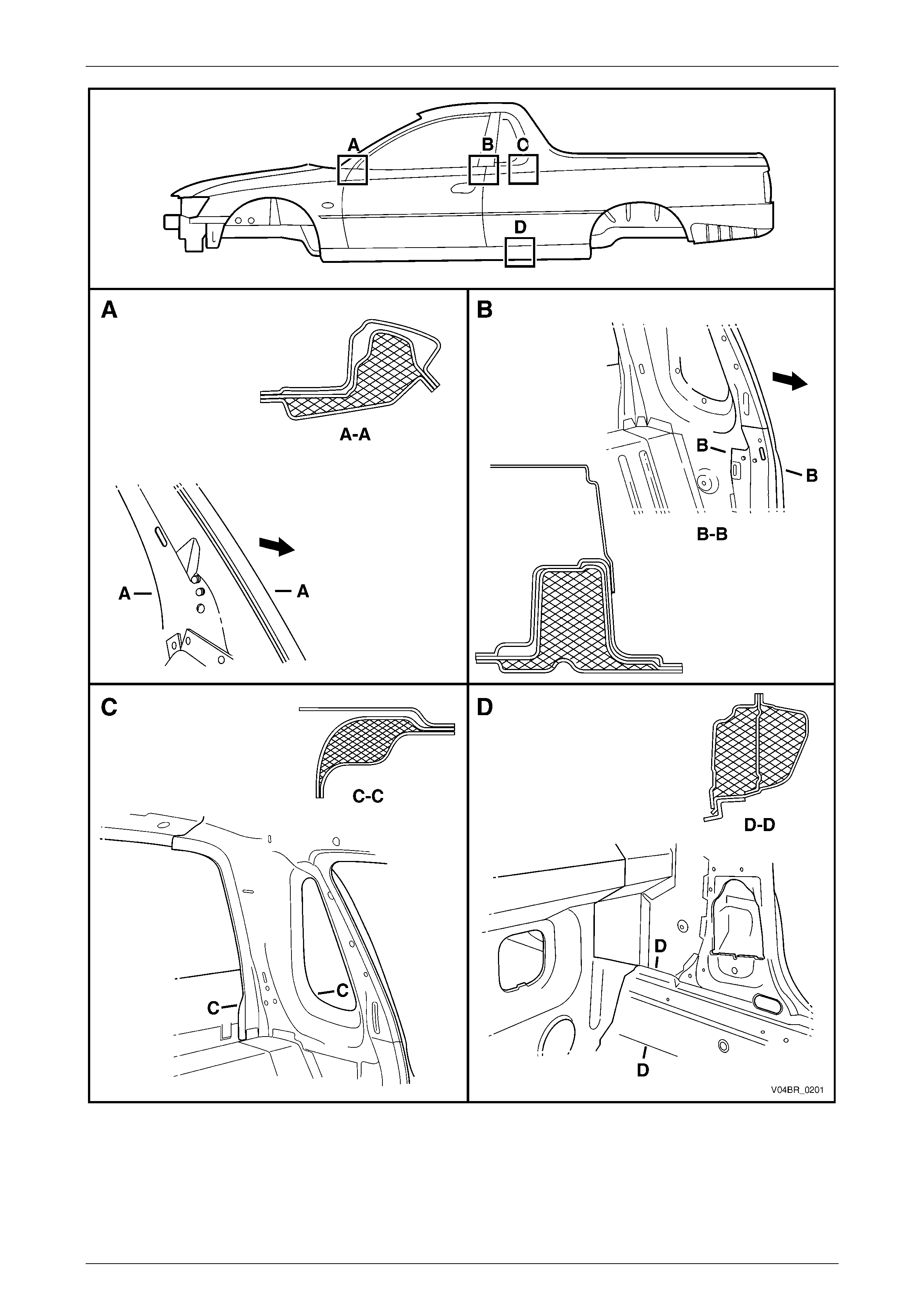
2 Cavity Foam
During manufacture of the vehicle, cavity foam blocks are fitted within the hinge, centre and body lock pillars, and the
rocker panel, refer to Figure 2 – 1.
NOTE
Application of cavity foam in locations C and D
will be introduced early 2004.
This foam material, when subjected to a temperature of approximately 160°C, expands up to 10 times its original size to
seal the cavity and reduce noise transmission.
The use of this material poses no health and
safety risk to a repairer, unless it is heated to
temperatures associated with using oxy /
acetylene equipment or welding, as toxic
fumes will be emitted which must not be
inhaled.
Prior to welding or heating in the areas shown, the foam must first be removed – usually by cutting it out with a knife.
If a panel or section is replaced, or repair work is performed where the foam is removed, it must be replaced with a
commercially available equivalent, such as those listed, using the following procedures prior to final trim assembly.
CAVITY FOAM EQUIVALENTS
Brand Product
Sista Multi Purpose Foam
Ramset Expandable Polyurethane Foam
NOTE
The hinge pillar inner panel assembly and
quarter panel inner assembly service parts are
supplied with uncured foam blanks. These must
not be removed as they act as a support for the
aerosol cavity foam.
Always read and follow the directions and safety
instructions with the product prior to usage.
Selleys Space invader
Precautions Page 2–4
Page 2–4
Figure 2 – 1
Legend
A Hinge Pillar C Body Lock Pillar
B Centre Pillar D Rocker Panel
Precautions Page 2–5
Page 2–5
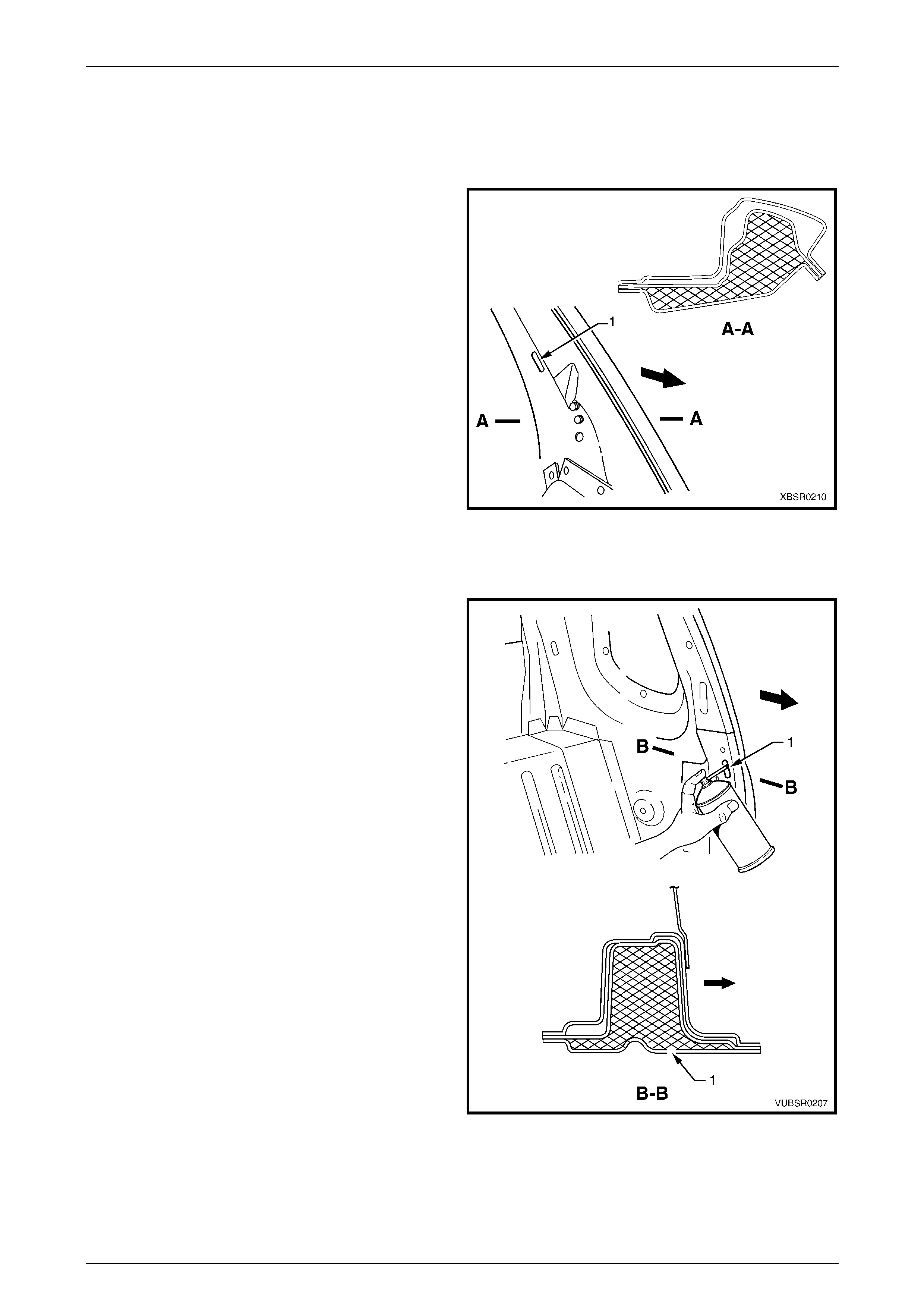
2.1 Cavity Foam – Replace
Hinge Pillar
1 For the hinge pillars, insert the nozzle of the aerosol
into the trim clip slot (1) which is above the foam
blank.
2 Spray foam into the cavity for several seconds while
drawing the nozzle out. Fill the area to a height of
approximately 50 mm.
3 Once cured, remove a small amount of foam using a
probe to enable the trim clip to seat correctly.
Figure 2 – 2
Centre Pillar
1 For the centre pillars, insert the nozzle of the aerosol
into the trim clip slot (1) which is above the foam
blank.
2 Spray foam into the cavity for several seconds while
drawing the nozzle out. Fill the area to a height of
approximately 50 mm.
3 Once cured, remove a small amount of foam using a
probe to enable the trim clip to seat correctly.
Figure 2 – 3
Precautions Page 2–6
Page 2–6
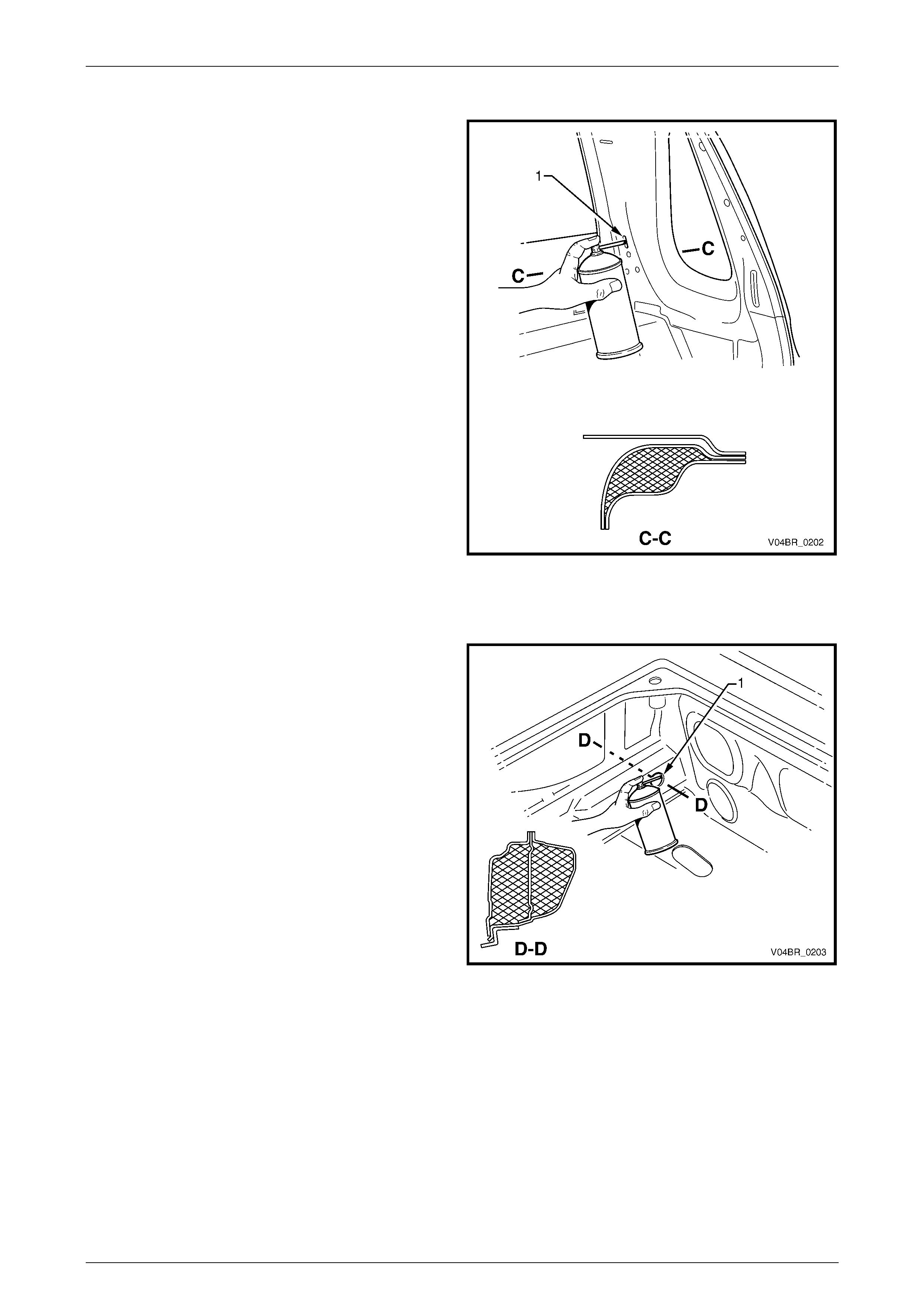
Body Lock Pillar
1 For the body lock pillars, insert the nozzle into the trim
locating hole (1) which is above the foam blank.
2 Spray foam into the cavity between the lock pillar
reinforcement and quarter panel inner for several
seconds while drawing the nozzle out. Fill the area to
a height of approximately 50 mm.
3 Once cured, remove a small amount of foam from the
locating hole using a probe to enable the trim stud to
seat correctly.
Figure 2 – 4
Rocker Panel
1 For the rocker panels, insert the nozzle into the inner
rocker panel hole (1) within the fuel tank cavity.
2 Spray foam into the cavity between the door opening
frame, quarter panel inner and inner rocker panel for
several seconds for a length of approximately 50 mm.
Figure 2 – 5