Body Const ruct i on Page 3–1
Page 3–1
Section 3
Body Construction
ATTENTION
Before performing any service operation or other procedure described in this Section, refer to Section 00
Warnings, Cautions and Notes in the MY 2004 VY and V2 Series Service Information and Section 2
Precautions in the MY 2003 VY and V2 Series Service Information Supplement, Body Structure Repair, for
correct workshop practices with regard to safety and/or property damage.
The Structure of the MY 2004 VY and V2
Series body shell has been developed using
complex design and development techniques.
In addition to meeting all required standards,
the vehicle body is also a critical part of the
overall safety systems. It is therefore
imperative the repair procedures described
here are adhered to during all vehicle body
repairs.
1 General Information............................................................................................................................... 2
2 Body Structure Panels .......................................................................................................................... 3
2.1 Front End and Underbody.....................................................................................................................................3
2.2 Upperbody Structure .............................................................................................................................................6
2.3 Body Assembly ......................................................................................................................................................8
3 Body Sealing, Adhesives And Deadeners ........................................................................................ 10
3.1 Acrylic Spot Weld Sealer (Item 2) .......................................................................................................................12
3.2 Joint Sealer (Item 3).............................................................................................................................................15
3.3 Adhesive – Anti-Flutter (Item 5) ..........................................................................................................................21
3.4 Adhesive – Structural (Item 6).............................................................................................................................22
3.5 Spray-On Deadener..............................................................................................................................................24
3.6 Deadener Panels and Insulators.........................................................................................................................25

Body Const ruct i on Page 3–2
Page 3–2
1 General Information
With the following exceptions MY 2004 VY and V2 Series Body Construction information carries over from MY 2003 VY
and V2 Series vehicles.
Coupe:
• Body structure panels
• Body sealing, adhesives and deadeners
For information not contained within this Section, refer to Section 3D Body Construction – Coupe in the MY 2003 VY and
V2 Series Service Information Supplement, Body Structure Repair.

Body Const ruct i on Page 3–3
Page 3–3
2 Body Structure Panels
The following tables and illustrations describe the body structure assemblies and panels that are available for service
replacement.
NOTE
Always refer to your authorised Retailer for spare
parts availabil ity config urati on s .
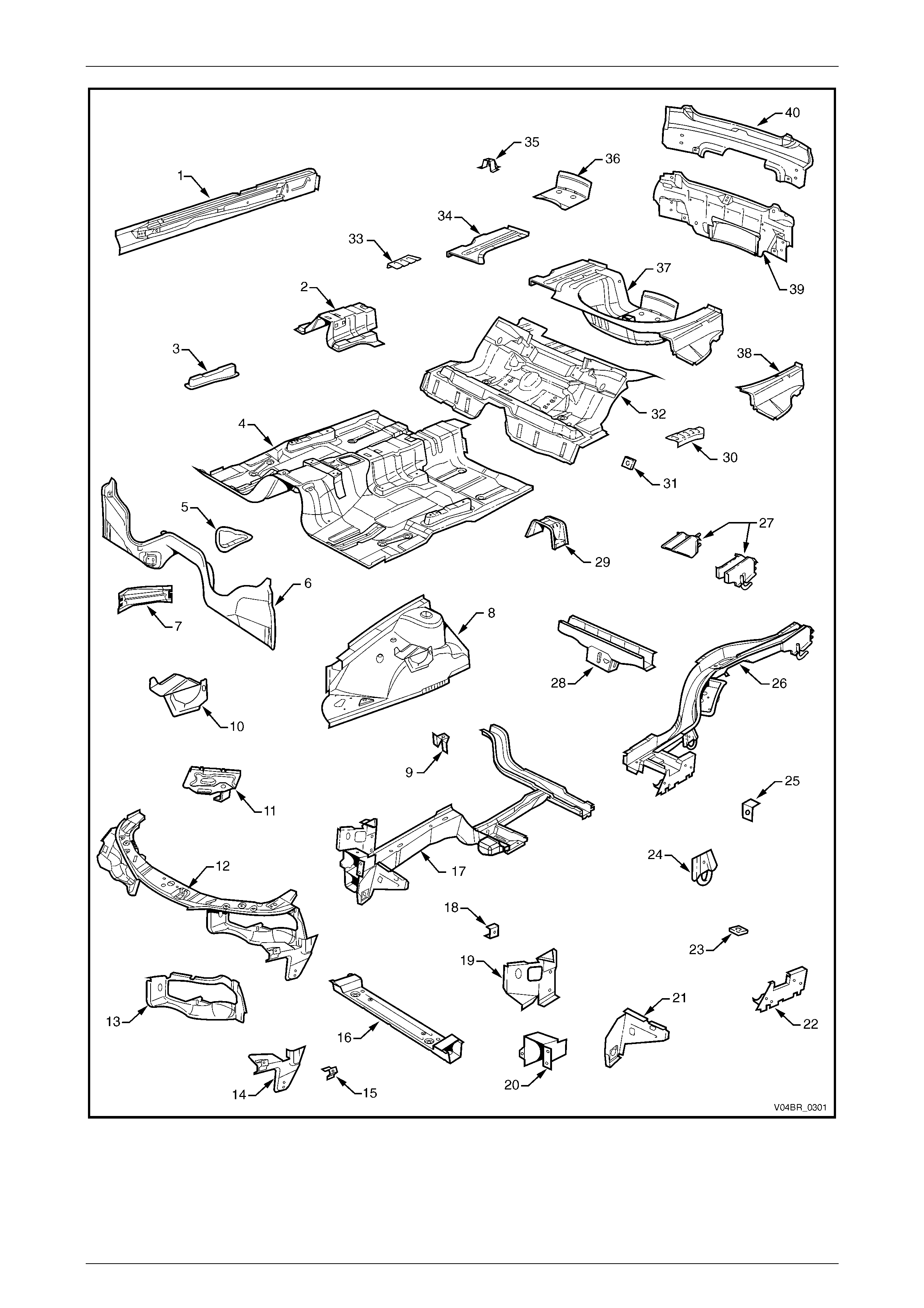
2.1 Front End and Underbody
The rear side rail assembly (26) contains
a reinforcement that is made from High
Strength Low Alloy Steel, refer to Figure 3 – 1.
If damaged, the reinforcement must not
be heated or straightened, therefore, as it is
not serviced separately, the entire rear side
rail assembly must be replaced. Refer to
Section 2, 9 Special Steel Precations in the
MY 2003 VY and V2 Series Service
Informtation Supplement, Body Structure
Repair for further information.
Body Const ruct i on Page 3–4
Page 3–4
Figure 3 – 1

Body Const ruct i on Page 3–5
Page 3–5
Legend
1 Inner Rocker P anel Assembl y
2 Seat Inner Bracket Assembly
3 Seat Outer Bracket Assembly
4 Front Floor Panel Assembly
5 Transmission Support Bracket
6 Front Floor Panel Extension
7 Front Side Rail Brace
8 Front Wheelhouse Panel Assembly
9 Horn Bracket Assembly
10 ABS Modulator Bracket Assembly
11 Battery Tray Assembly
12 Front End Panel Assembly
13 Headlamp Panel
14 Headlamp and Front Fascia Mount Bracket
15 Fender Front Lower Bracket
16 Radiator Lower Support Ass em bly
17 Front Side Rail Assembly
18 Radiator Side Mounting B rack et
19 Front Wheelhouse Bracket Assembly
20 Front Bumper Impact Bar Bracket
21 Front Wheelhouse Panel Bracket
22 Rear Floor Panel Outer Extension
23 Rear Suspension Support Mount Plate
24 Rear Tie Down Assembly
25 Rear Brake Hose Bracket
26 Rear Side Rail Assembly
27 Rear Bumper Impact Bar Brace Ass embly, LH / RH
28 Crossm ember Assem bly No. 2
29 Propeller Shaft Hanger Assembly
30 Rear Floor Panel Reinforcement , LH
31 Rear Seat Belt Anchor Plate Assembly
32 Rear Floor Panel Assembly
33 Rear Floor Panel Reinforc ement, RH
34 Rear Compartment Floor Panel Outer Extensi on, RH
35 Spare Wheel Anchor Plate Assembly
36 Fuel Tank Support Reinforcement Assembly
37 Rear Compartment Floor Panel Assembl y
38 Rear Compartment Floor Panel Outer Extensi on, LH
39 Rear End Panel Assembly
40 Rear End Lower Panel
Body Const ruct i on Page 3–6
Page 3–6
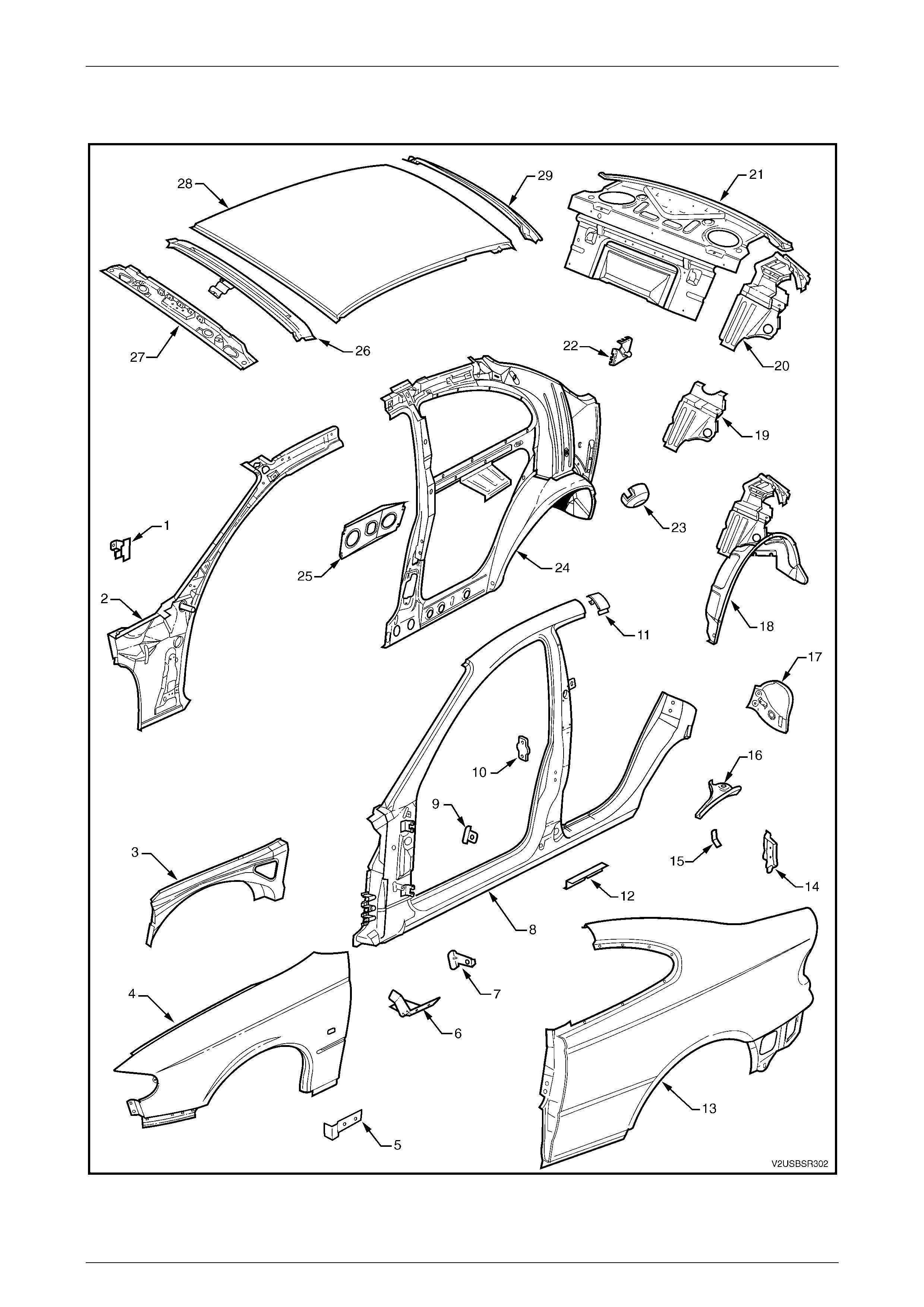
2.2 Upperbody Structure
Figure 3 – 2

Body Const ruct i on Page 3–7
Page 3–7
Legend
1 Hinge Pillar Trim Panel Bracket
2 Hinge Pillar Inner Panel Assembly
3 Front Wheelhouse Panel Upper Side Rail
4 Front Fender
5 Rocker Panel Moulding Bracket
6 Fender Lower Rear Bracket
7 Fender Rear Bracket
8 Door Opening Frame Assembly
9 Fender Upper Rear Bracket
10 Front Door Striker Anchor Plate
11 Body Pillar I nner Panel Rei nforc em ent
12 Underbody Jack i ng Locator
13 Rear Quarter Panel
14 Quarter Panel Lower Extension
15 Bracket - Rear Lamp Wiring Harness Extension
16 Quarter Panel Upper Extension
17 Tail Lamp Housing
18 Rear Wheelhouse Inner Panel Assembly
19 Rear Seat Back Panel Extensi on
20 Rear Seat Back Panel Extensi on Ass em bl y
21 Rear Window Panel Assembly
22 Rear Compartment Lid Strut B racket Ass em bl y
23 Fuel Filler Pipe Housing, RH
24 Quarter Panel Inner Assembl y
25 Radio Quarter Speaker Bracket
26 Roof Bow Panel
27 Roof Front Header Panel
28 Roof Panel
29 Roof Rear Panel
Body Const ruct i on Page 3–8
Page 3–8
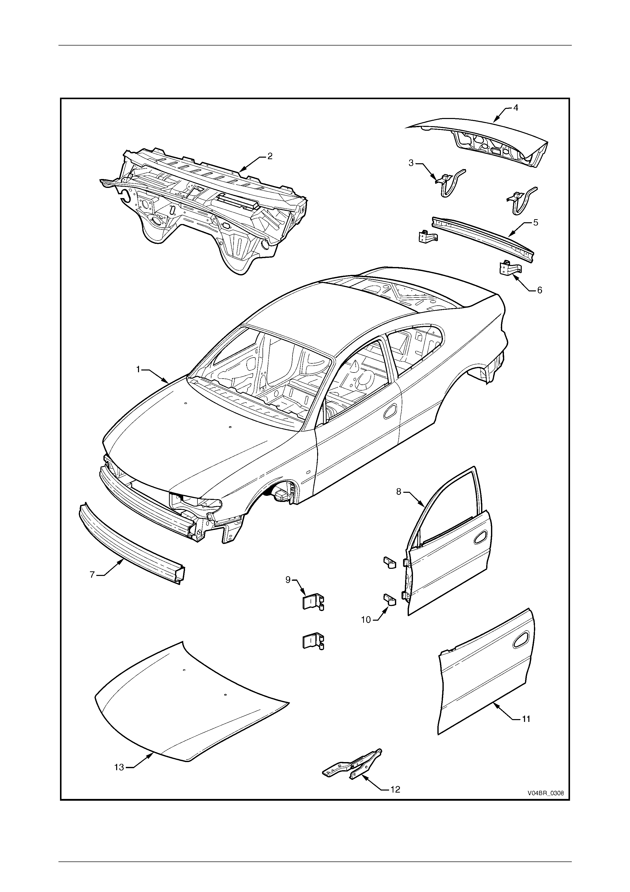
2.3 Body Assembly
Figure 3 – 3

Body Const ruct i on Page 3–9
Page 3–9
Legend
1 Body Assembly
2 Dash Panel Assembly
3 Rear Compartment Lid Hi nge Assembly
4 Rear Compartment Lid Assembly
5 Rear Bumper Impact Bar
6 Rear Bumper Impact Bar Bracket Assembly
7 Front Bumper Impact Bar Assembly
8 Front Door Assembly
9 Front Door Hinge (Body Side)
10 Front Door Hinge (Door Side)
11 Front Door Outer Panel
12 Hood Hinge Assembly
13 Hood assembly

Body Const ruct i on Page 3–10
Page 3–10
3 Body Sealing, Adhesives And
Deadeners
This Section details the sealers, adhesives and deadeners used in the MY 2004 V2 Series Coupe body shell. It is
imperative that the correct materials are used and the directions on the product are always followed.
NOTE
When replacing any sealer, adhesive or
deadener, ensure the finish meets that of the
original applic atio n.
The commercially available products listed
below will meet the required standards. Other
products may be available that meet the
performance characteristics, however before
their use, the product manufacturer should be
contacted to check its suitability.
Weld Through Primer (Item 1)
Although not used in manufacture, Weld Through Primer is recommended for all service repair lap and flange joints
where Acrylic Spot Weld Sealer (Item 2) is not used. Weld Through Primer aids in corrosion protection of the joint.
Acrylic Spot Weld Sealer (Item 2)
Used in joints that require sealing additional to Joint Sealer (Item 3). It is applied to the joint flange prior to the mating of
panels. Refer to Fi gure 3 – 4 to Figure 3 – 6.
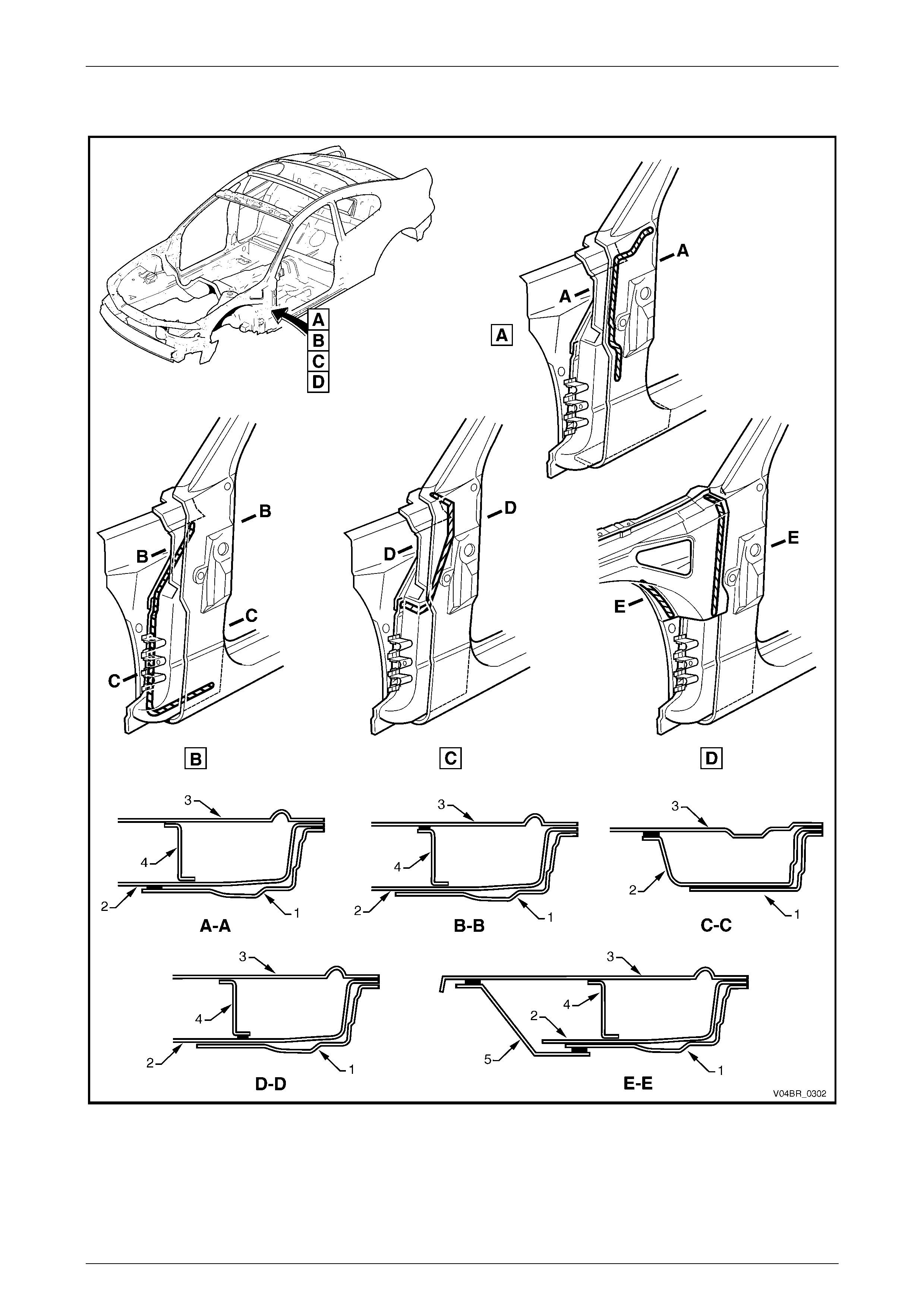
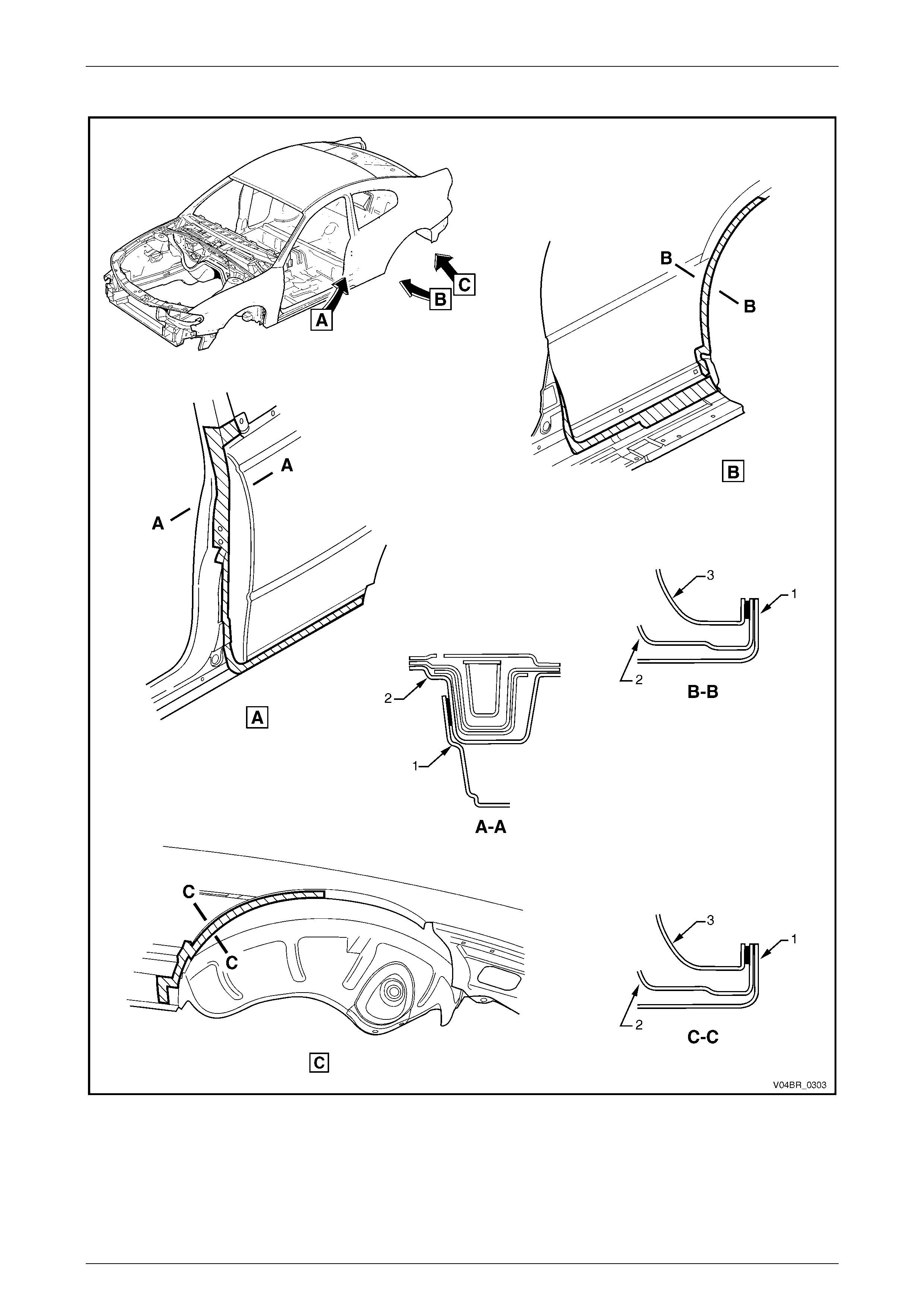
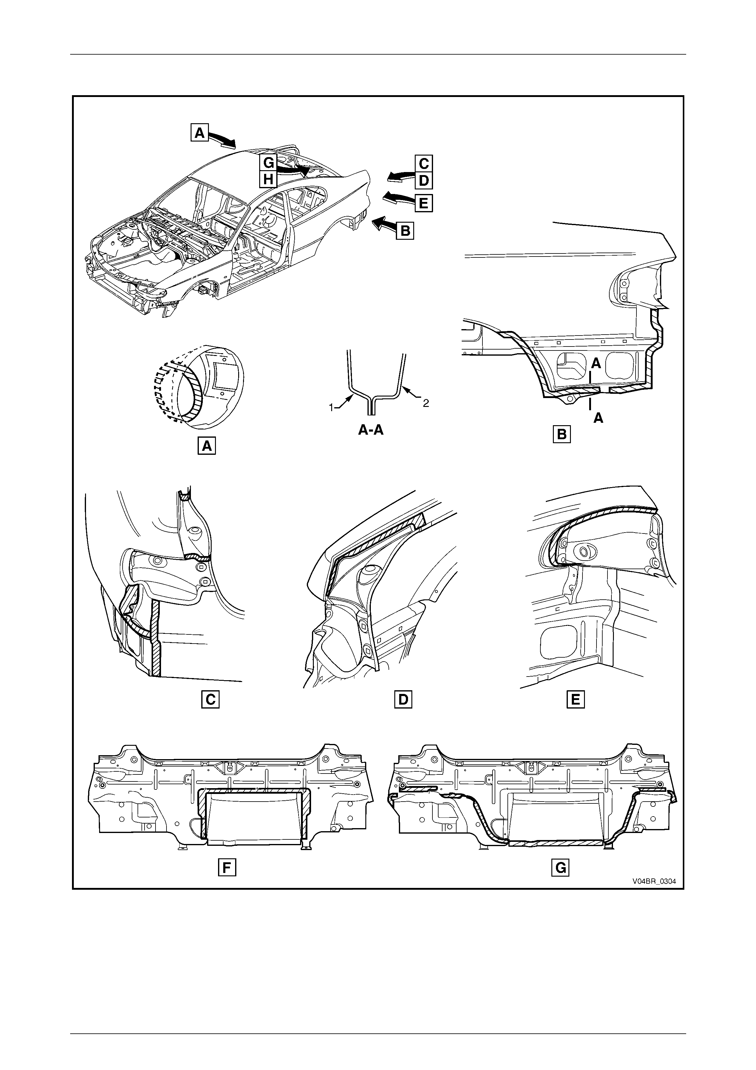
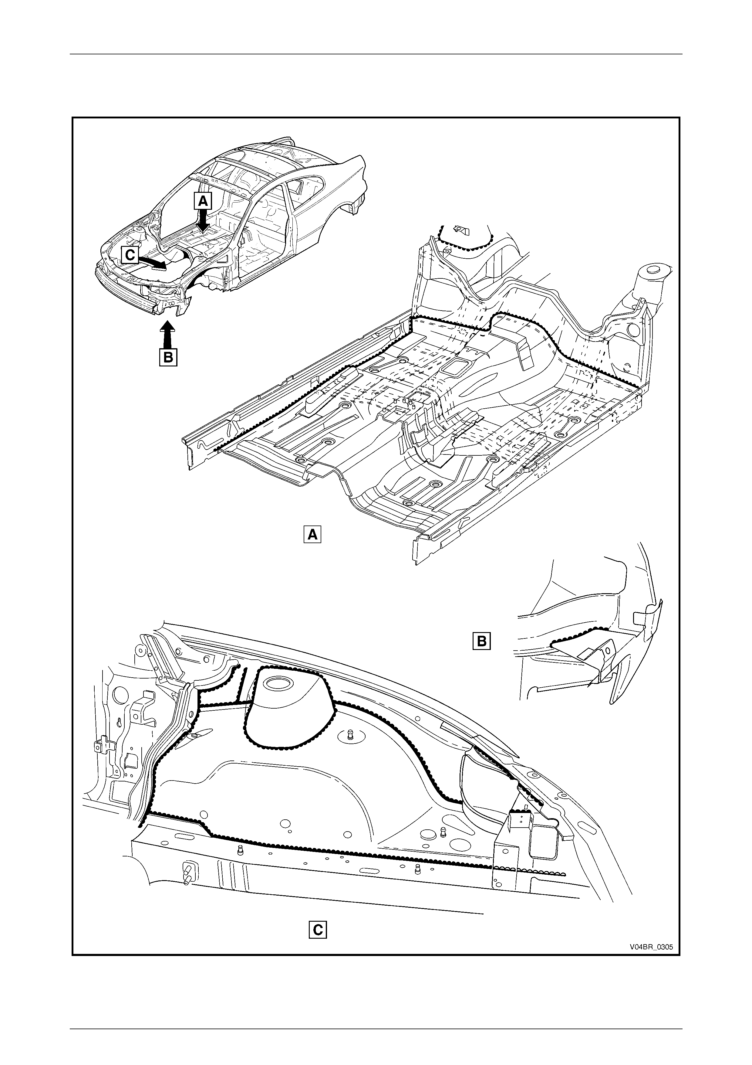
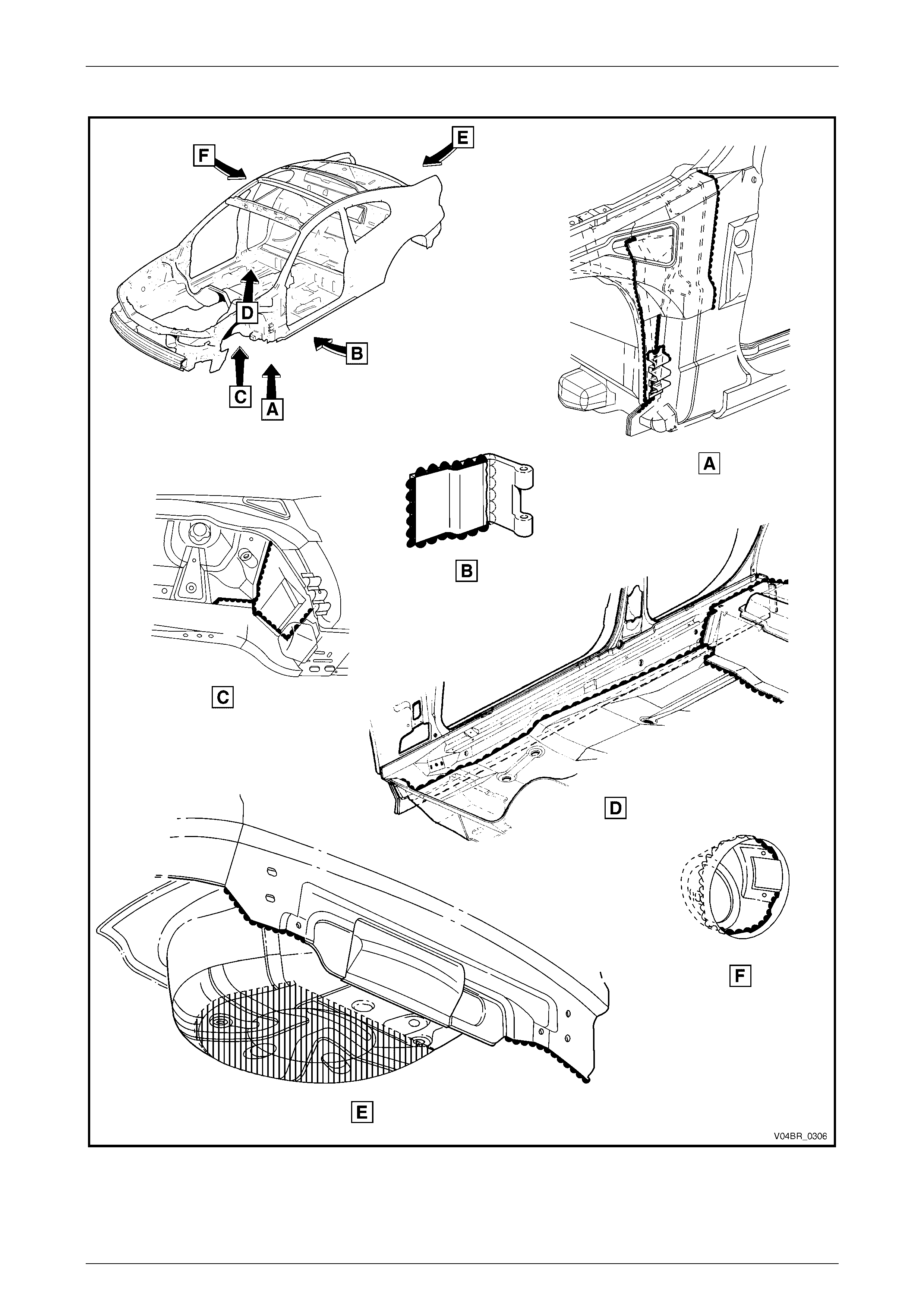
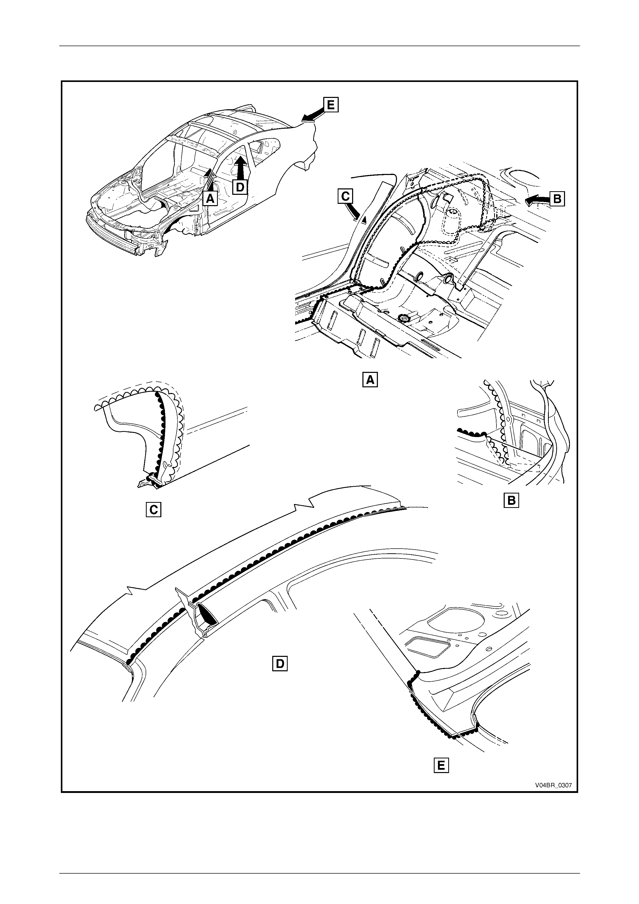
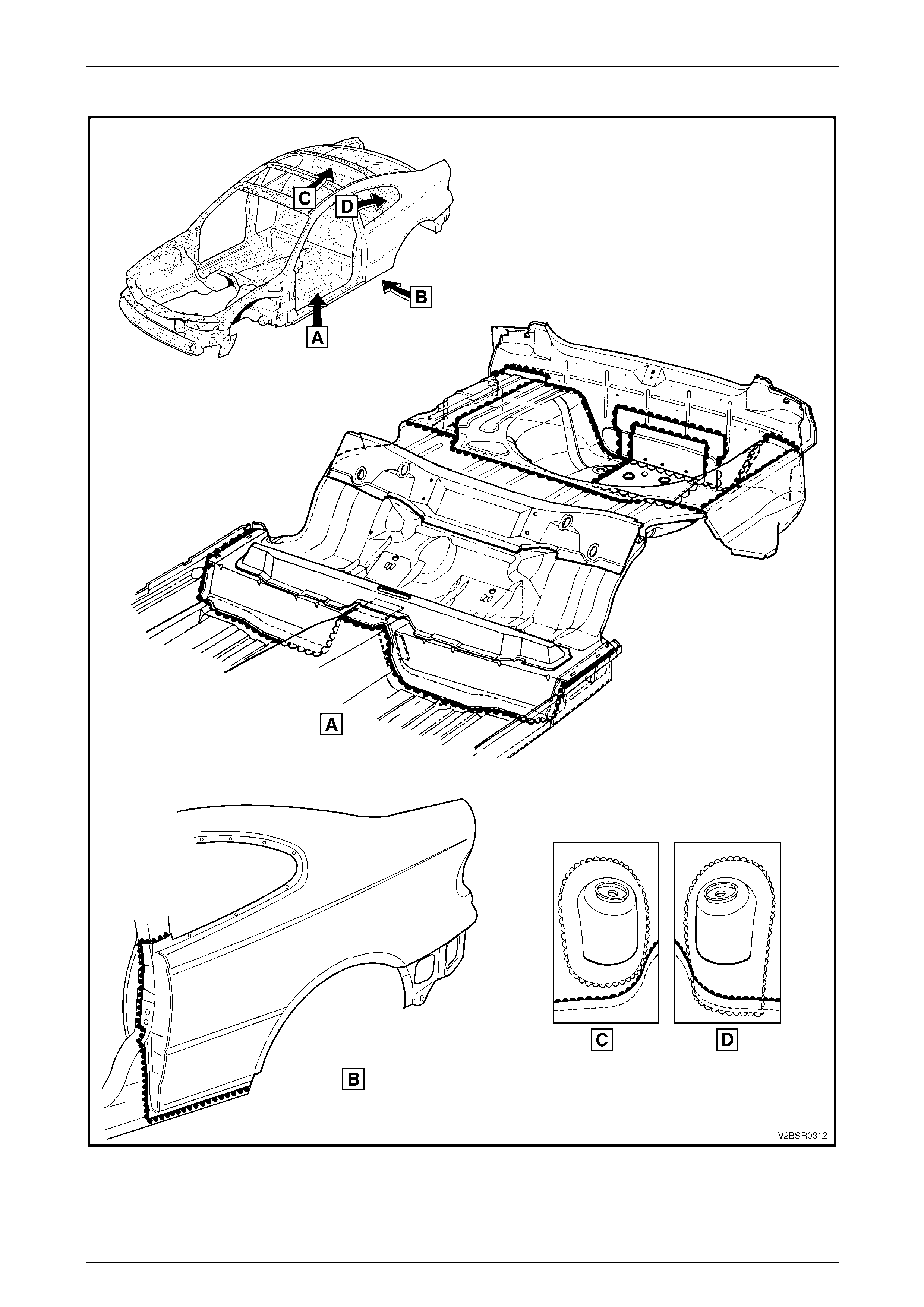
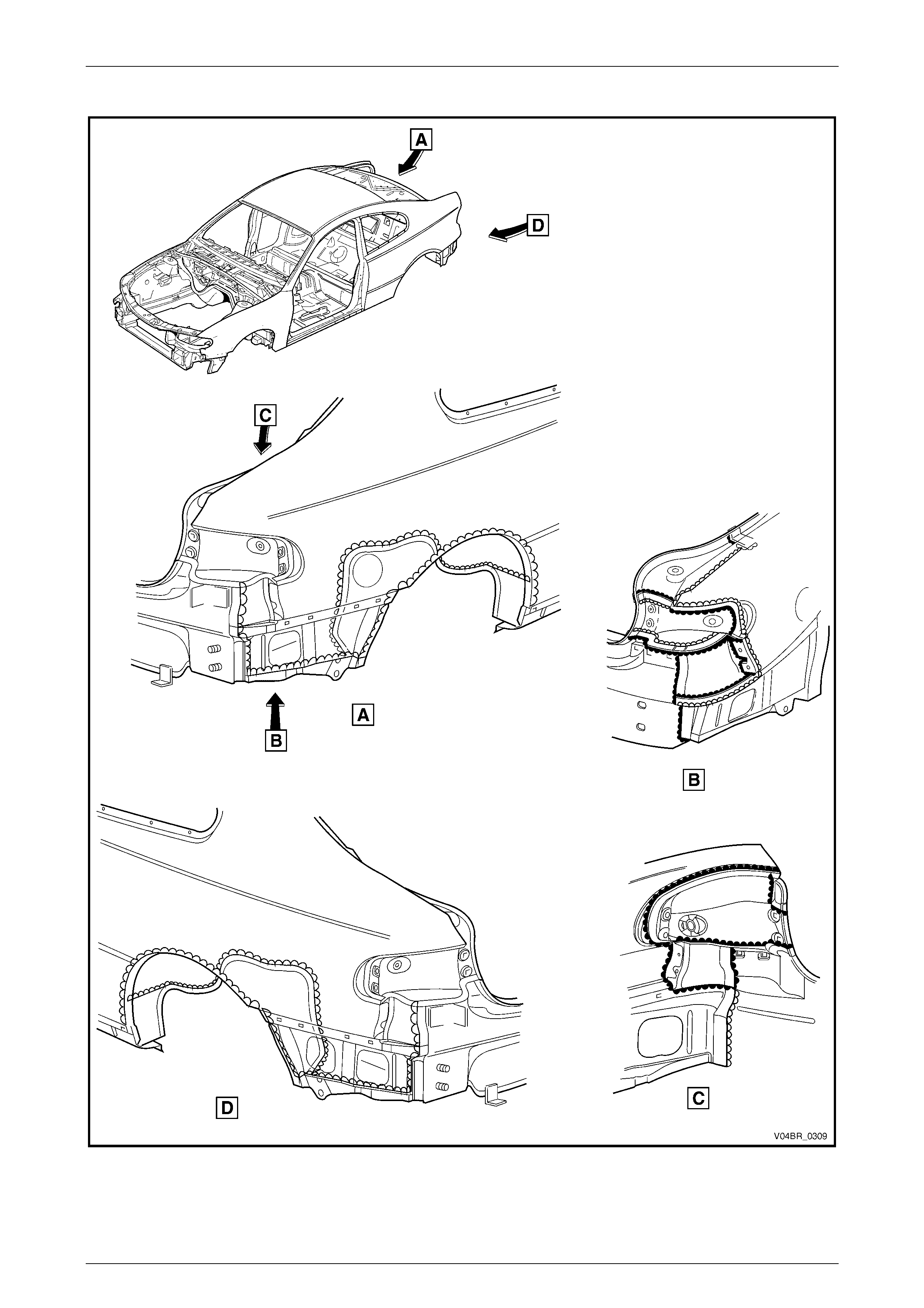
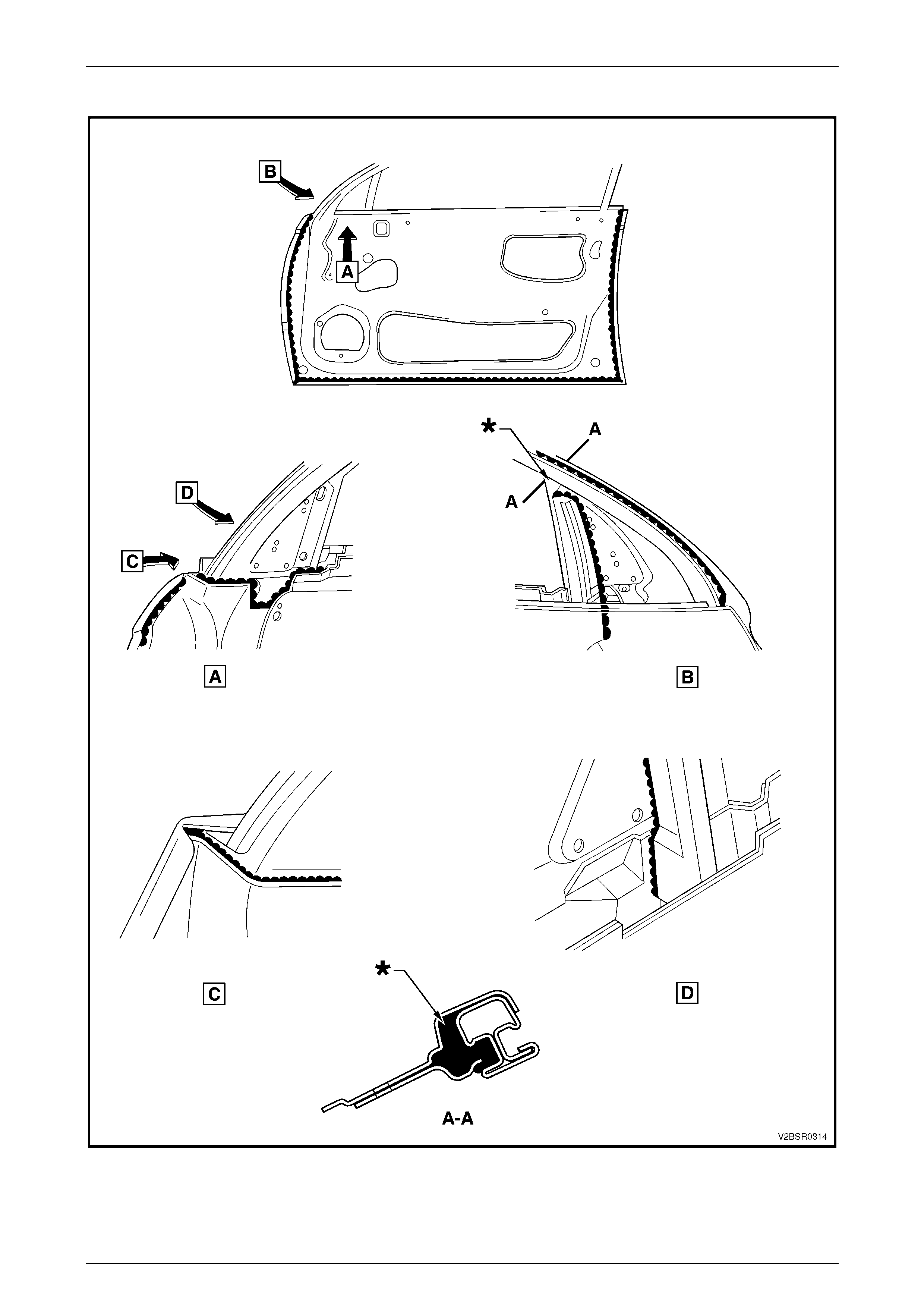
Joint Sealer (Item 3)
Primarily used for sealing joints to achieve a watertight seal. It seals notches, cut-outs and holes. Joint sealer should be
applied after priming, prior to application of the top coat. Refer to Figure 3 – 7 to Figure 3 – 12.
NOTE
• View E in Figure 3 – 8, illustrates the
underside of the spare wheel-well. Following
priming, this area is sprayed with sealer
(rather than deadener) to a minimum
thickness of 2.5 mm and has a rough finish.
This procedure is important due to the
mounting of the fuel tank below it.
• During production a heat fusible patch is
applied along the joint of the rear window
panel assembly, refer to Figure 3 – 9 View E.
This patch is not serviced as the heat required
to fuse it is beyond the capabilities of the
repairer. Joint sealer may be applied and
finished to produce a smooth surface.
Hand Putty (Item 4)
Hand putty, also known as caulking compound, is used in the areas marked *, refer to Figure 3 – 12.
Adhesive – Anti-Flutter (Item 5)
While used as a filler between an inner and outer panel to reduce panel flex, Anti-Flutter adhesive also aids rigidity and
assists in dispersing loads over a larger area. Refer to Figure 3 – 13 for locations.

Body Const ruct i on Page 3–11
Page 3–11
Adhesive – Structural (Item 6)
Critical to the strength and rigidity of the vehicle, the correct adhesive must be used for service repairs. Using an
adhesive that is too weak will reduce the performance of the joint. Using an adhesive that is too strong can also effect the
performance of the joint, compromising the vehicle’s crash performance and safety system’s operation. This adhesive is
a 2-part system. Refer to Figure 3 – 14 and Figure 3 – 15 for locations.
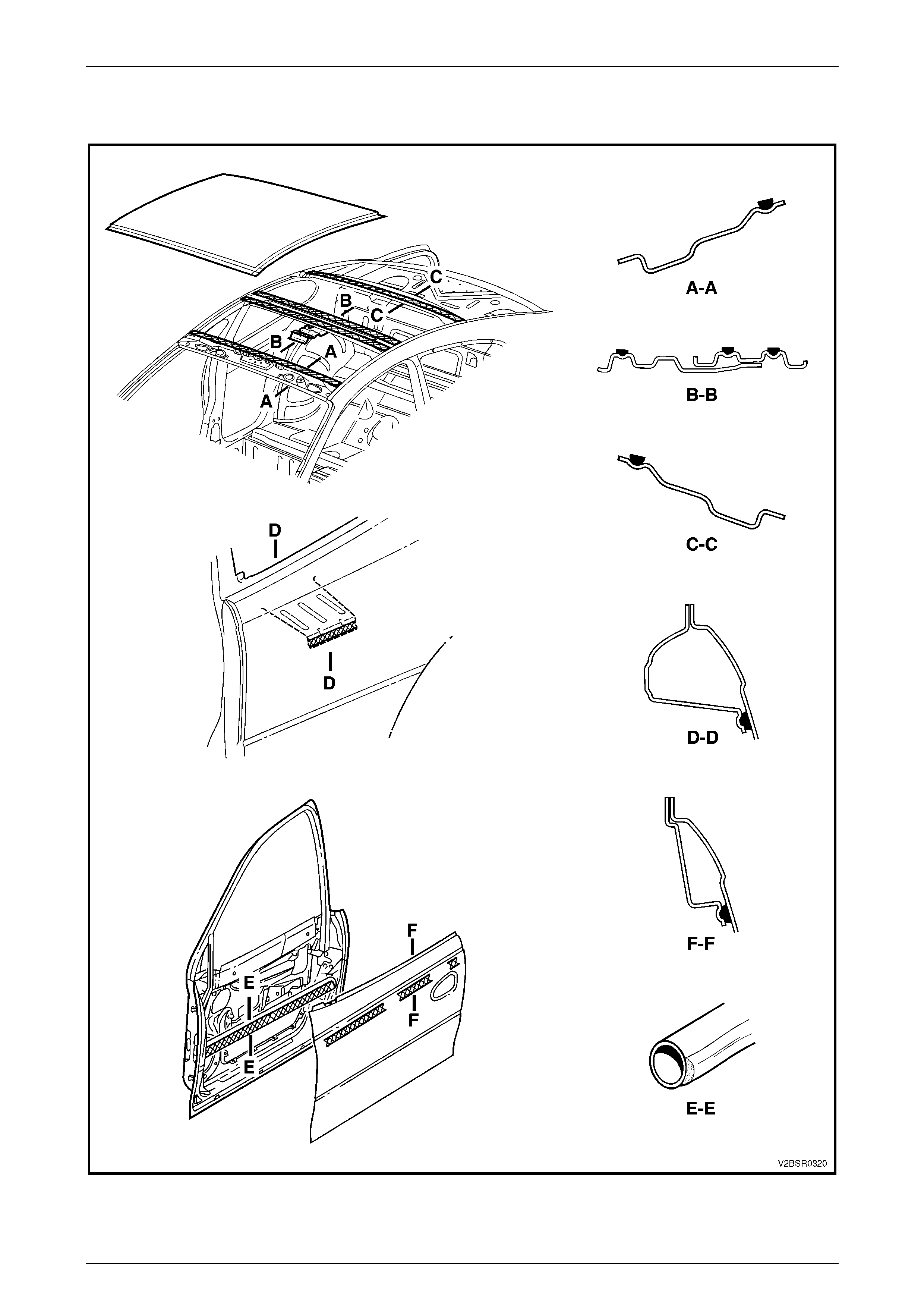
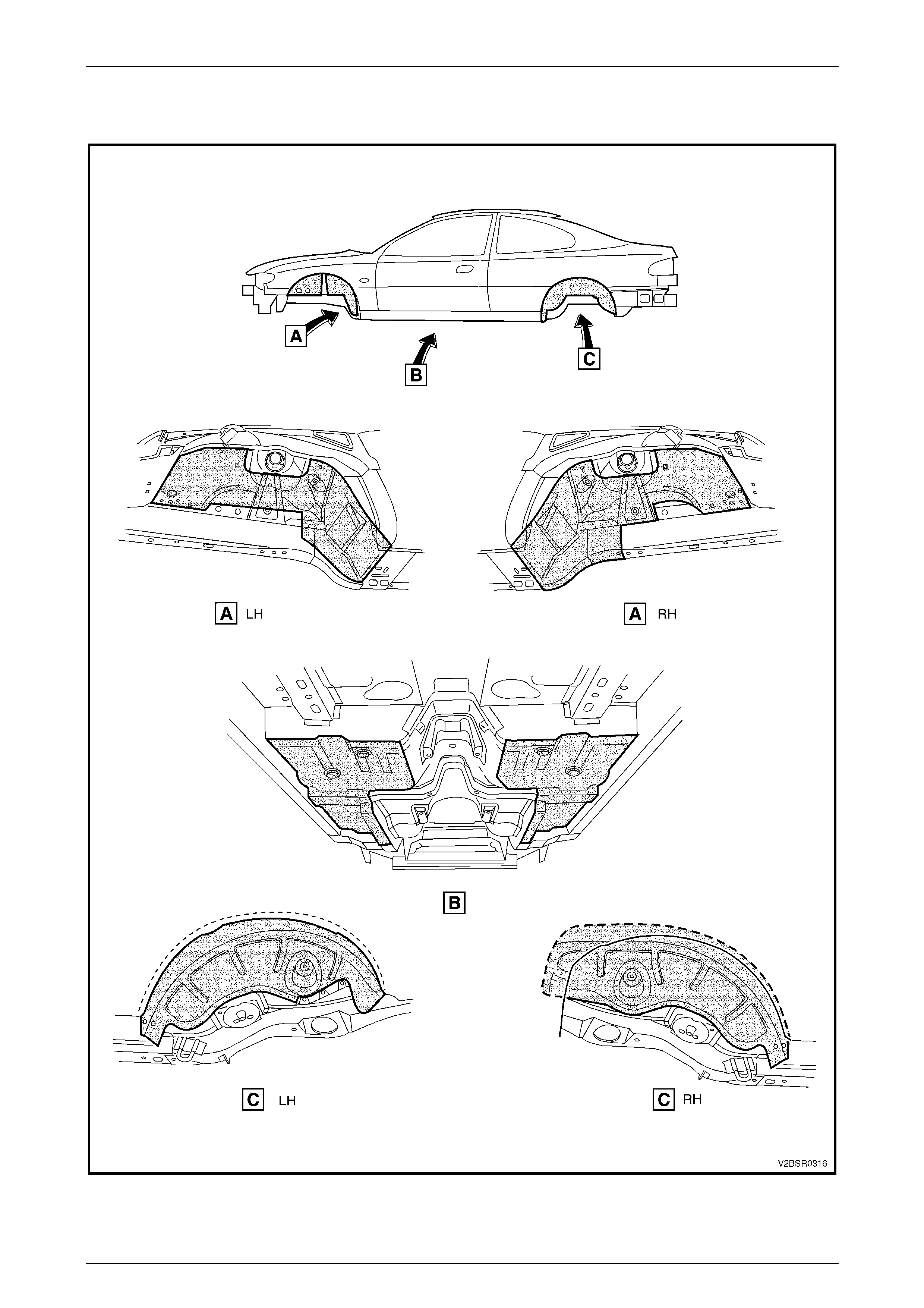
Spray-on Deadener (Item 7)
This deadener is sprayed onto the body shell after painting. It is used in the wheel-wells and on the under side of the
floor pan. A minimum thickness of 1.5 mm is required in these applications. Refer to Figure 3 – 16 for locations.
Deadener Panels
Deadener panels are sold pre-cut as Service Parts. They are installed with the coloured side up and diamond embossed
side down. The panels are installed prior to painting and some are heat fused to the body shell. Refer to Figure 3 – 17 to
Figure 3 – 20 for locations.
Sealer / Adhesive / Deadener Commercially Available Equivalents
Item No. Item Name Manufacturer Product Name
1 Weld Through Primer Refer to supplier
2 Acrylic Spot Weld Sealer Lord (Fusor) Fusor #800 / #801
3 Joint Sealer Sprayable: Lord (Fusor)
Extruded beads: Lord (Fusor)
3M
Visible Seams
-self leveling: Lord (Fusor)
3M
-non sag: Lord (Fusor)
3M
Fusor #802
Fusor #800 / #801
Automix 8308
Fusor #122 / #125
Automix 8307
Fusor #123 / #126
Automix 8308
4 Hand Putty Lord (Fusor)
3M
Fusor #800 / #801
Automix 8307
5 Adhesive - Anti Flutter Lord (Fusor) Fusor #124
6 Adhesive - Structural
(Two-Part) Lord (Fusor)
3M
Fusor #108 B
Automix 8115
7 Spray-on Deadener Henkel Terophon 2000-13
NOTE
Special tools may be required to apply some
materials, refer to your supplier for further
information.
Body Const ruct i on Page 3–12
Page 3–12
3.1 Acrylic Spot Weld Sealer (Item 2)
Figure 3 – 4
Legend
1 Door Opening Frame Assembly
2 Hinge Pillar Reinforcement
3 Shroud Side Panel
4 Hinge Pillar Closing Plate
5 Front Wheelhouse Brace
Body Const ruct i on Page 3–13
Page 3–13
Acrylic Spot Weld Sealer (Item 2) Continued
Figure 3 – 5
Legend
1 Rear Quarter Panel
2 Door Opening Frame Assembly 3 Quarter Panel Inner Assembl y
Body Const ruct i on Page 3–14
Page 3–14
Acrylic Spot Weld Sealer (Item 2) Continued
Figure 3 – 6
Legend
1 Rear Quarter Panel 2 Quarter Panel Inner Assembl y
Body Const ruct i on Page 3–15
Page 3–15
3.2 Joint Sealer (Item 3)
Figure 3 – 7
Body Const ruct i on Page 3–16
Page 3–16
Joint Sealer (Item 3) Continued
Figure 3 – 8
Body Const ruct i on Page 3–17
Page 3–17
Joint Sealer (Item 3) Continued
Figure 3 – 9
Body Const ruct i on Page 3–18
Page 3–18
Joint Sealer (Item 3) Continued
Figure 3 – 10
Body Const ruct i on Page 3–19
Page 3–19
Joint Sealer (Item 3) Continued
Figure 3 – 11
Body Const ruct i on Page 3–20
Page 3–20
Joint Sealer (Item 3) Continued and Hand Putty (Item 4)
Figure 3 – 12
Body Const ruct i on Page 3–21
Page 3–21
3.3 Adhesive – Anti-Flutte r (Item 5)
Figure 3 – 13
Body Const ruct i on Page 3–22
Page 3–22
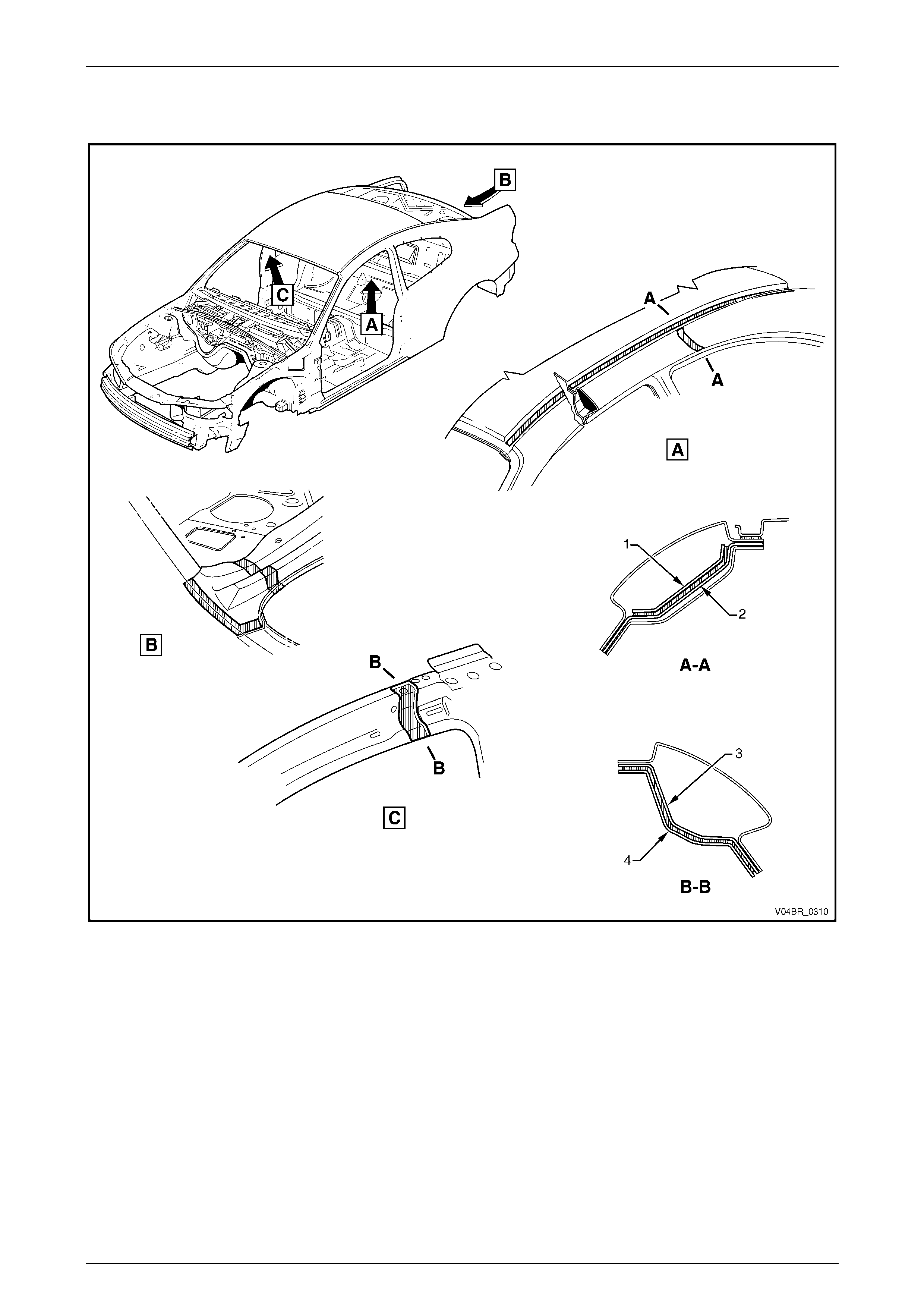
3.4 Adhesi ve – Structural (Item 6)
Figure 3 – 14
Legend
1 Centre Pillar Upper Reinforcement
2 Lock Pillar Rei nforcement 3 Hinge-Pillar Inner
4 Quarter Panel Inner
Body Const ruct i on Page 3–23
Page 3–23
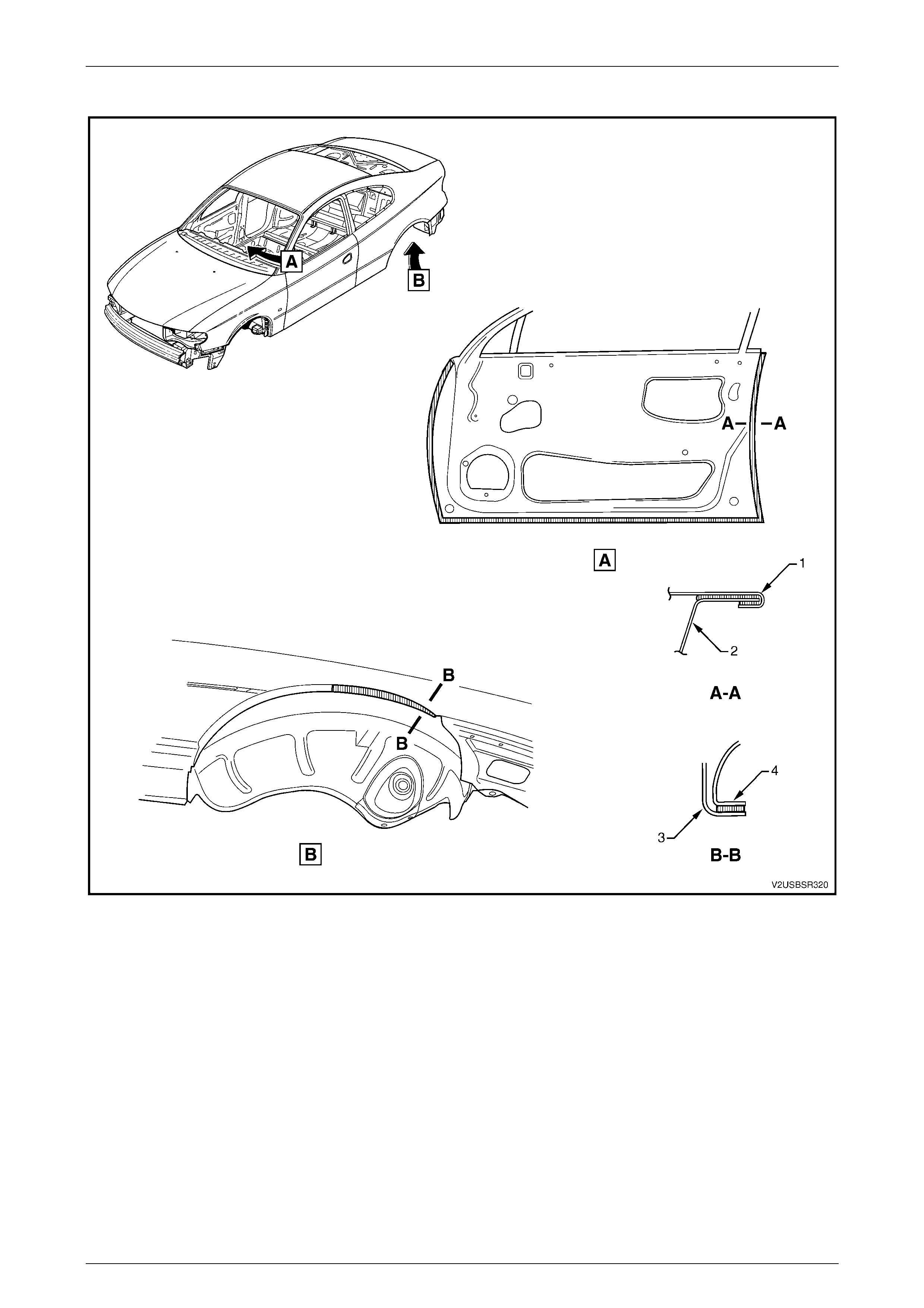
Adhesive – Structural (Item 6) Continued
Figure 3 – 15
Legend
1 Front Door Outer Panel
2 Front Door Inner Panel 3 Rear Quarter Panel
4 Quarter Panel Inner
Body Const ruct i on Page 3–24
Page 3–24
3.5 Spray-On Deadener
Figure 3 – 16
Body Const ruct i on Page 3–25
Page 3–25
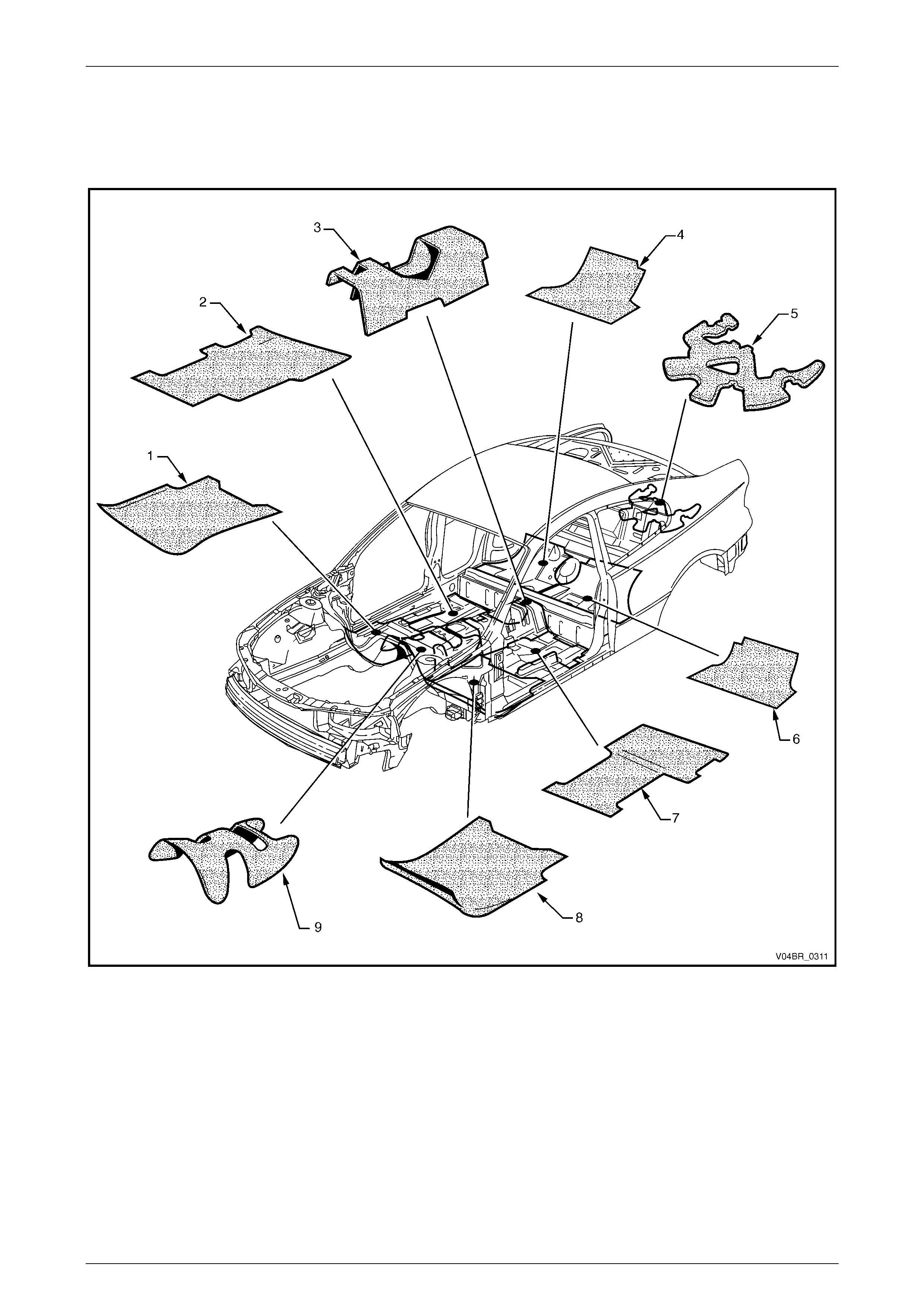
3.6 Deadener Panels and Insulators
The deadener panels shown are heat fusible type. They are to be installed with the diamond embossed side down. Use a
heat gun, heat lamps or such to cure each deadener sheet.
Figure 3 – 17
Legend
1 Front Floor Deadener, RH
2 Rear Floor Deadener, RH
3 Rear Floor Deadener, Centre
4 Rear Seat Floor Deadener, RH
5 Spare Wheel Well Deadener
6 Rear Seat Floor Deadener, LH
7 Rear Floor Deadener, LH
8 Front Floor Deadener, LH
9 Front Floor Deadener, Centre
Body Const ruct i on Page 3–26
Page 3–26
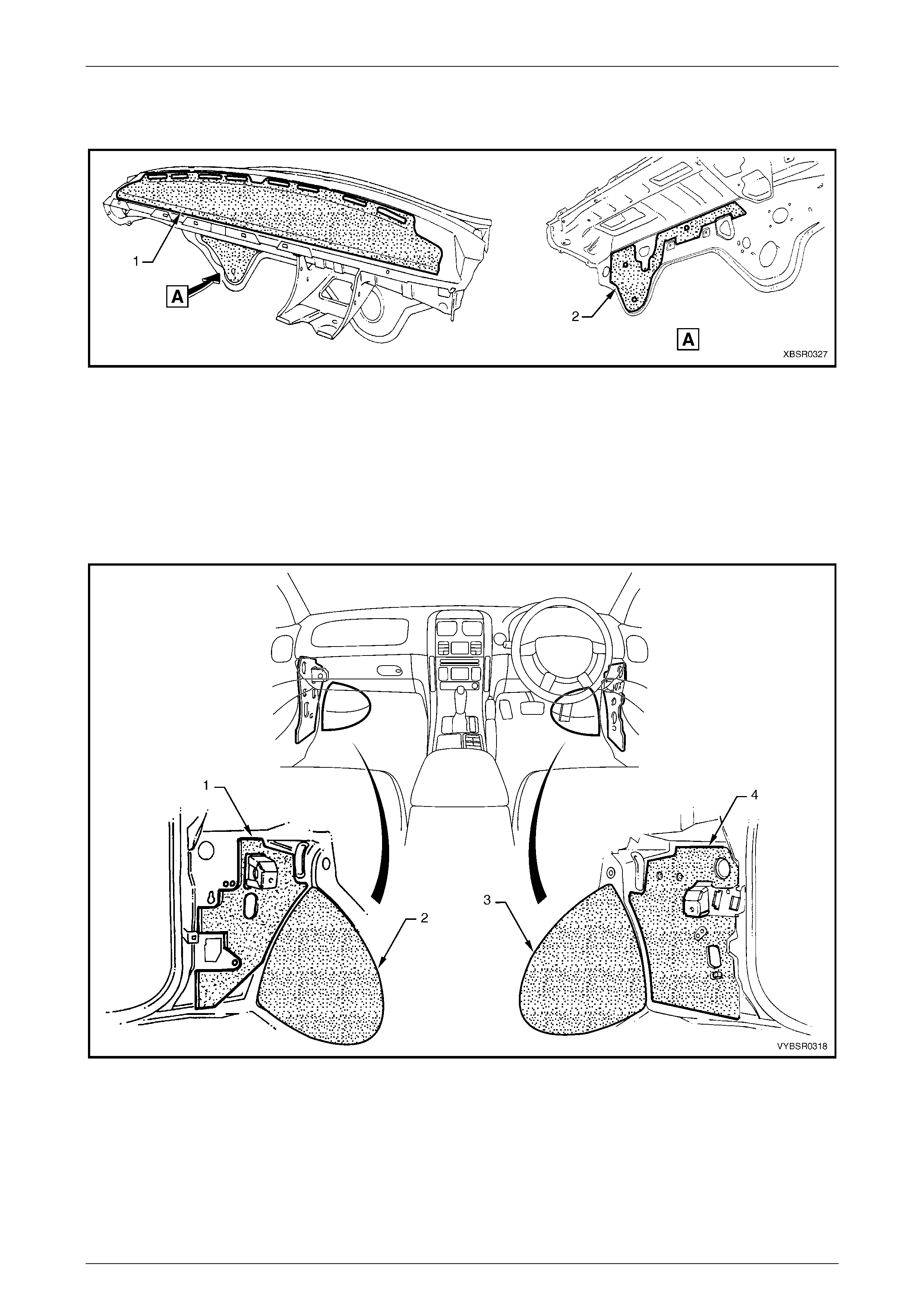
The insulator (1) is self-adhesive, refer to Figure 3 – 18. To install, remove the backing paper and attach the insulator
ensuring any cut-outs align with brackets etc. Smooth the insulator firmly into position. The deadener (2) is a heat cure
type and is attached as previously described.
Figure 3 – 18
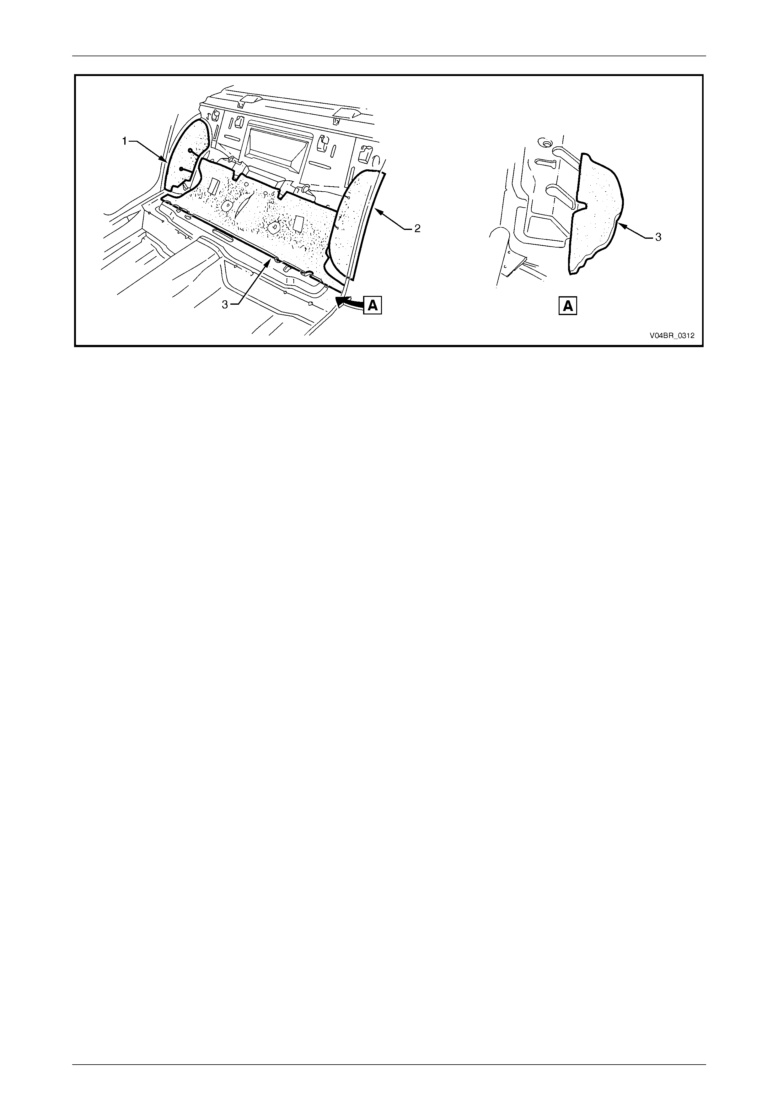
The deadeners and insulators are self-adhesive, refer to Figure 3 – 19 and Figure 3 – 20. Remove the backing paper
and attach the insulator ensuring any cut-outs align with brackets etc. Smooth the insulator firmly into position.
NOTE
Ensure the notch in the rear seat insulators (3) in
Figure 3 – 20 is aligned with the slot in the rear
seat ramp as shown A.
Figure 3 – 19
Legend
1 Cowl Side Insul ator, LH
2 Front Floor Extension Deadener, LH 3 Front Floor Extension Deadener, RH
4 Cowl Side Insul ator, RH
Body Const ruct i on Page 3–27
Page 3–27
Figure 3 – 20
Legend
1 Rear Seat Wheelhouse Insulator, LH
2 Rear Seat Wheelhouse Insulator, RH 3 Rear Seat Insulator