Body Side Page 7–1
Page 7–1
Section 7
Body Side
ATTENTION
Before performing any service operation or other procedure described in this Section, refer to Section 00
Warnings, Cautions and Notes in the MY 2004 VY and V2 Series Service Information and Section 2
Precautions in the MY 2003 VY and V2 Series Service Information Supplement, Body Structure Repair, for
correct workshop practices with regard to safety and/or property damage.
The Structure of the MY 2004 VY and V2
Series body shell has been developed using
complex design and development techniques.
In addition to meeting all required standards,
the vehicle body is also a critical part of the
overall safety systems. It is therefore
imperative the repair procedures described
here are adhered to during all vehicle body
repairs.
1 General Information............................................................................................................................... 2
2 Service Operations................................................................................................................................3
2.1 Rear Quarter Panel – Replace...............................................................................................................................3
Remove ...................................................................................................................................................................3
Replace ...................................................................................................................................................................7

Body Side Page 7–2
Page 7–2
1 General Information
With the following exceptions, MY 2004 VY and V2 Series Body Side information carries over from MY 2003 VY and V2
Series vehicles.
• Rear quarter panel – Coupe.
For information not contained within this Section, refer to Section 7D Body Side – Coupe in the MY 2003 VY and V2
Series Service Information Supplement, Body Structure Repair.
When repairing the body side of the vehicle, care must be taken to ensure the structure is returned to its original
production configuration.
NOTE
It is imperative that the correct:
• Body adhesives, sealers, deadeners are used
when repairing the body structure of MY 2004
V2 vehicles. Refer to Section 3, 3 Body
Sealing, Adhesives and Deadeners.
• Cavity waxes are used when repairing the
body structure of MY 2004 V2 vehicles. Refer
to Section 3D, 6 Cavity Wax in the MY 2003
VY and V2 Series Service Information
Supplement, Body Structure Repair.
Body Side Page 7–3
Page 7–3
2 Service Operations
2.1 Rear Quarter Panel – Replace
NOTE
The rear quarter panel is not available as an
assembly with the tail lamp housing, quarter
panel upper extension, quarter panel lower
extension or fuel filler pipe housing (for right-hand
side).
This procedure details the removal of the rear quarter panel as an assembly with the above parts. For replacement of the
smaller panels not covered in this procedure, refer to Section 7 Body Side in the MY 2003 VY and V2 Series Service
Information Supplement, Body Structure Repair.
NOTE
Full replacement of the rear quarter panel
requires removal of the roof panel. An alternative
is also provided in this procedure where the panel
is joined through the lock-pillar, approximately
100 mm below the top of the rear window.
NOTE
Cavity Foam is used within the hinge, centre and
lock pillar cavities. Care is required when
repairing the vehicle in these areas, refer to
Section 2, 2.10 Cavity Foam in the MY 2003 VY
and V2 Series Service Information Supplement,
Body Structure Repair, prior to beginning work for
further information.
Remove
To avoid the possibility of fire, take particular
care when cutting or welding at the rear of the
vehicle. Remove the fuel tank and plug all fuel
lines.
1 Remove the adjacent bolt-on panels and components
as described in the appropriate Section in the
MY 2004 VY and V2 Series Service Information.
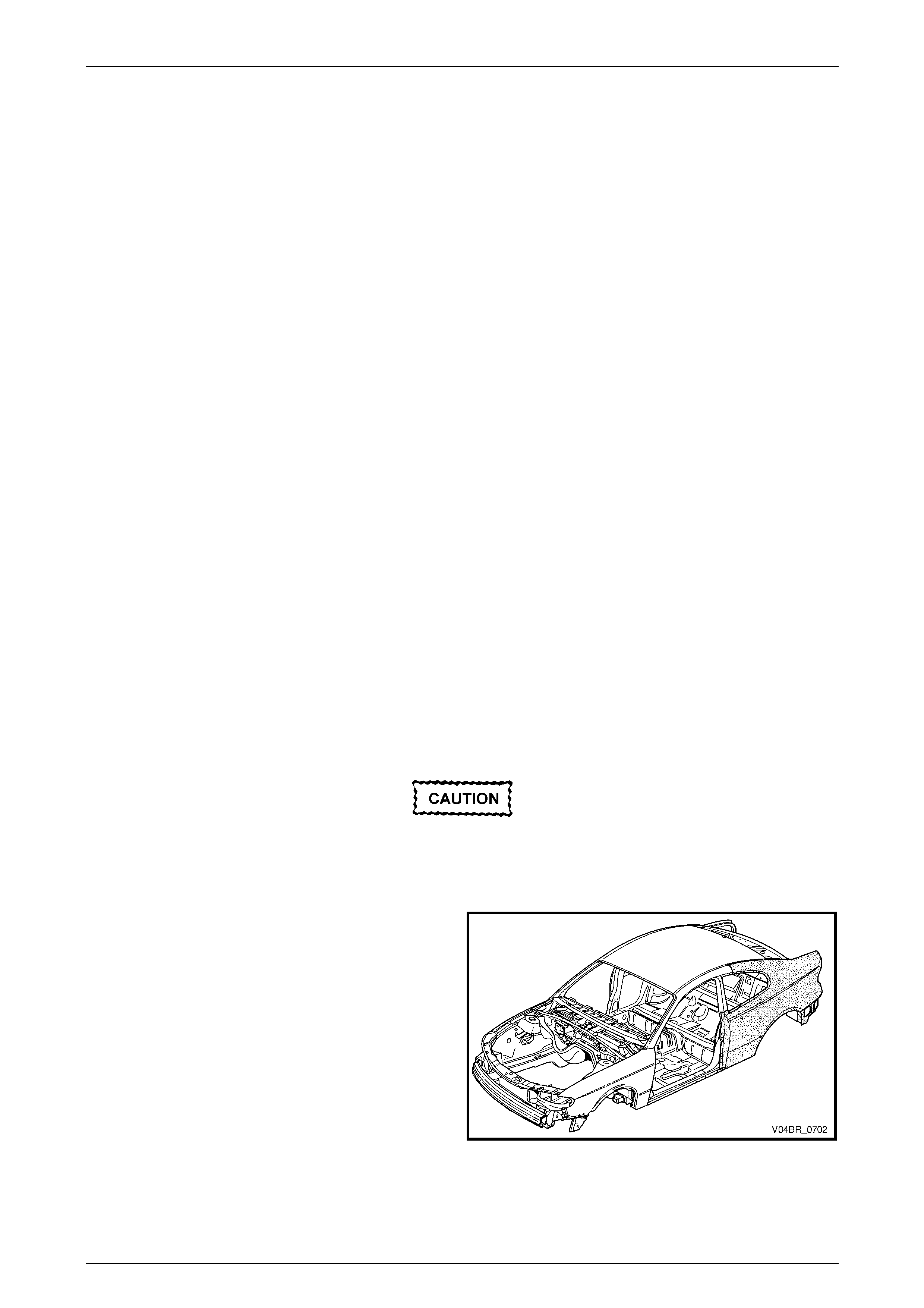
2 Remove the rear window and quarter window
assembly, refer to Section 1A6 Stationary Windows in
the MY 2004 VY and V2 Series Service Information.
Figure 7 – 1

Body Side Page 7–4
Page 7–4
3 Spot cut the tail lamp housing and quarter panel lower
extension from the rear end lower panel.
NOTE
If the tail lamp housing and quarter panel lower
extension are to remain, modify this procedure
accordingly.
4 Spot cut the rear quarter panel from the rear end lower
panel and rear compartment floor panel outer
extension.
5 Spot cut the welds attaching the rear quarter panel to
the quarter panel inner assembly and rear
compartment flo or panel outer extension. There are a
different number of welds on the left-hand panel to the
right-hand panel. Refer to Figure 7 – 3.
Figure 7 – 2
Figure 7 – 3
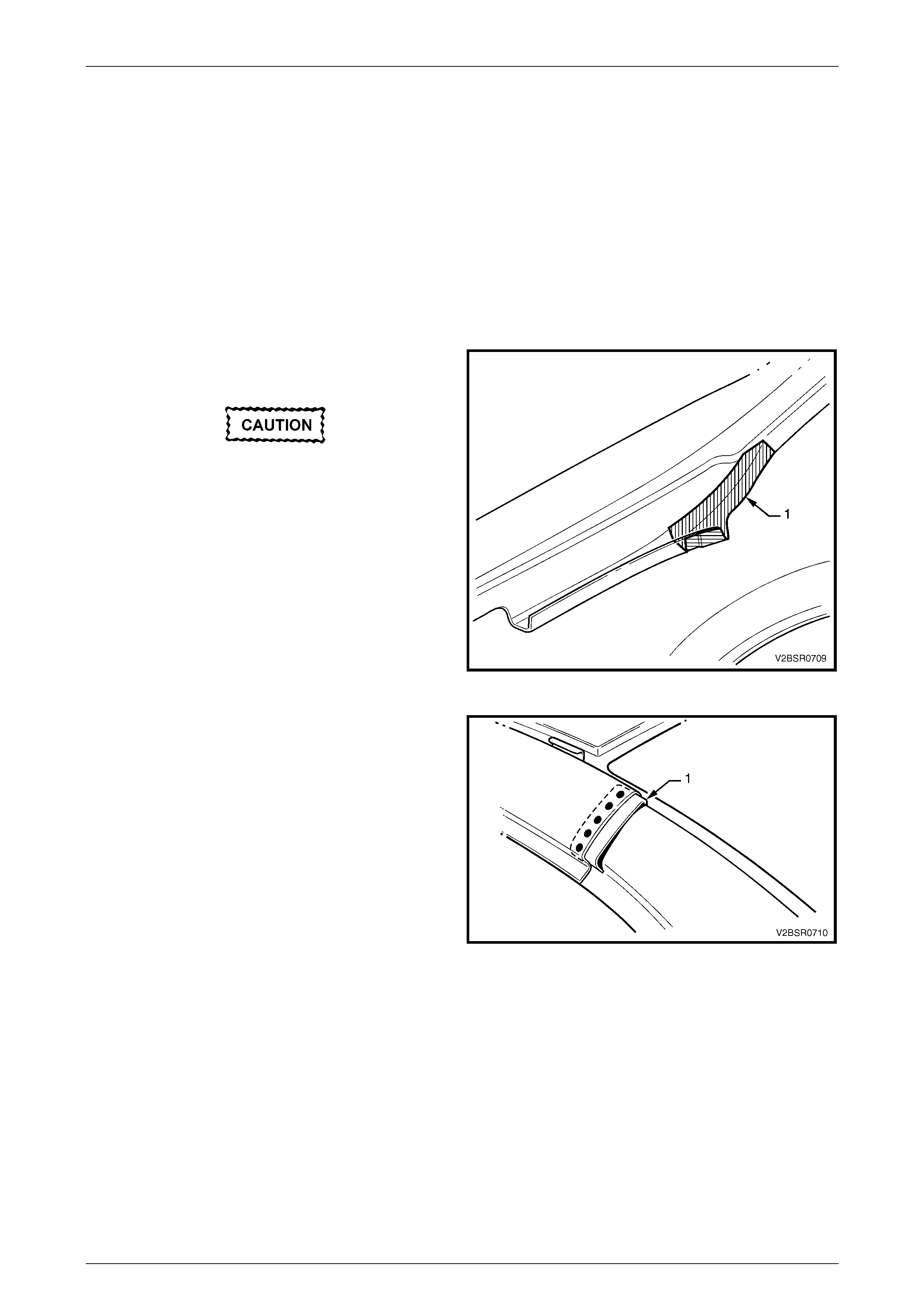
6 Spot cut the welds attaching the rear quarter panel to
the door opening frame assembly and quarter panel
inner assembly .
NOTE
Structural adhesive is applied in the area shown
(1). Removal of the panel may be made easier
by cutting the quarter panel around this area and
then grinding the flange off once the panel is
removed.
Figure 7 – 4
Body Side Page 7–5
Page 7–5
7 Spot cut the welds attaching the rear quarter panel to
the door opening frame assembly.
Figure 7 – 5
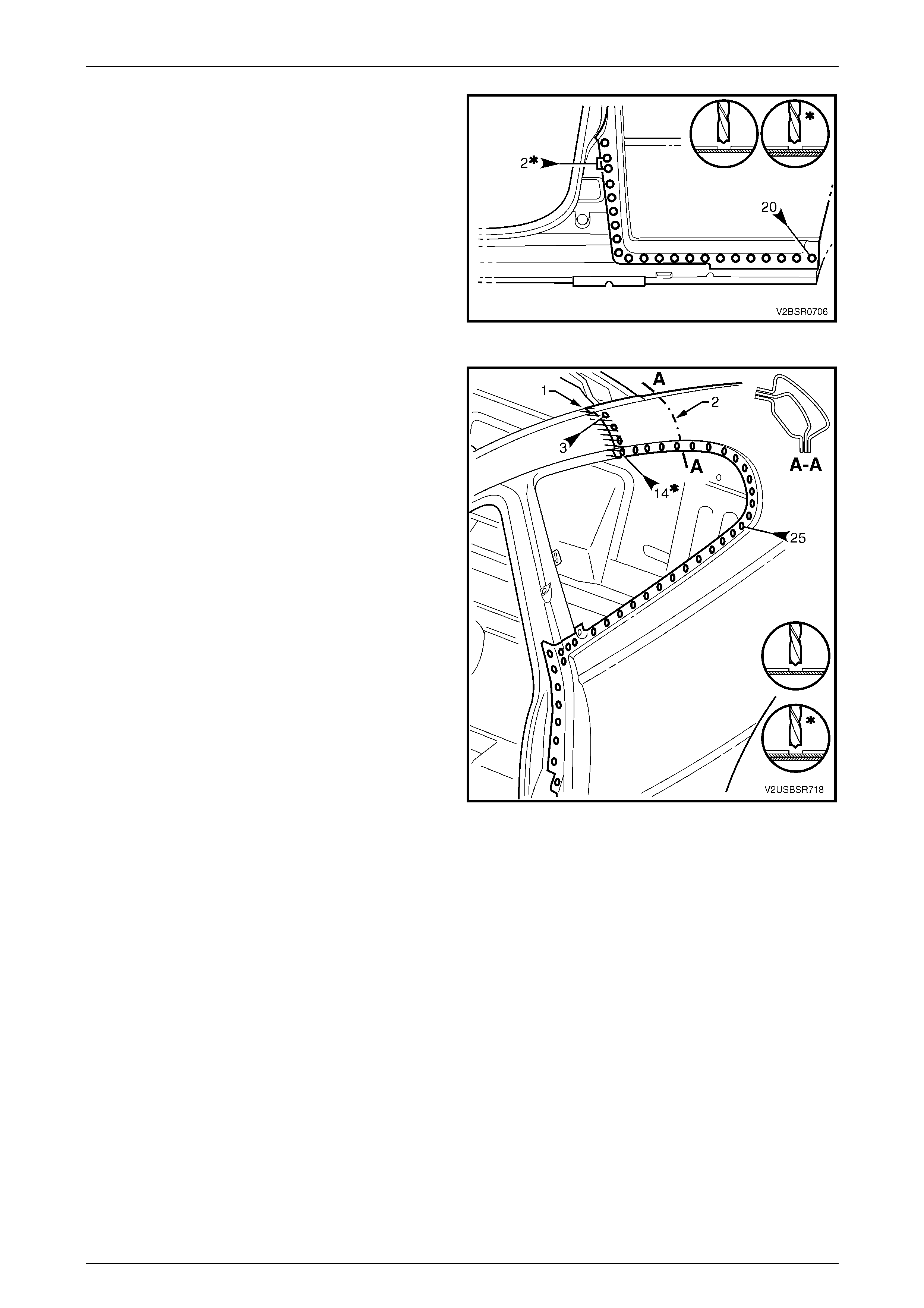
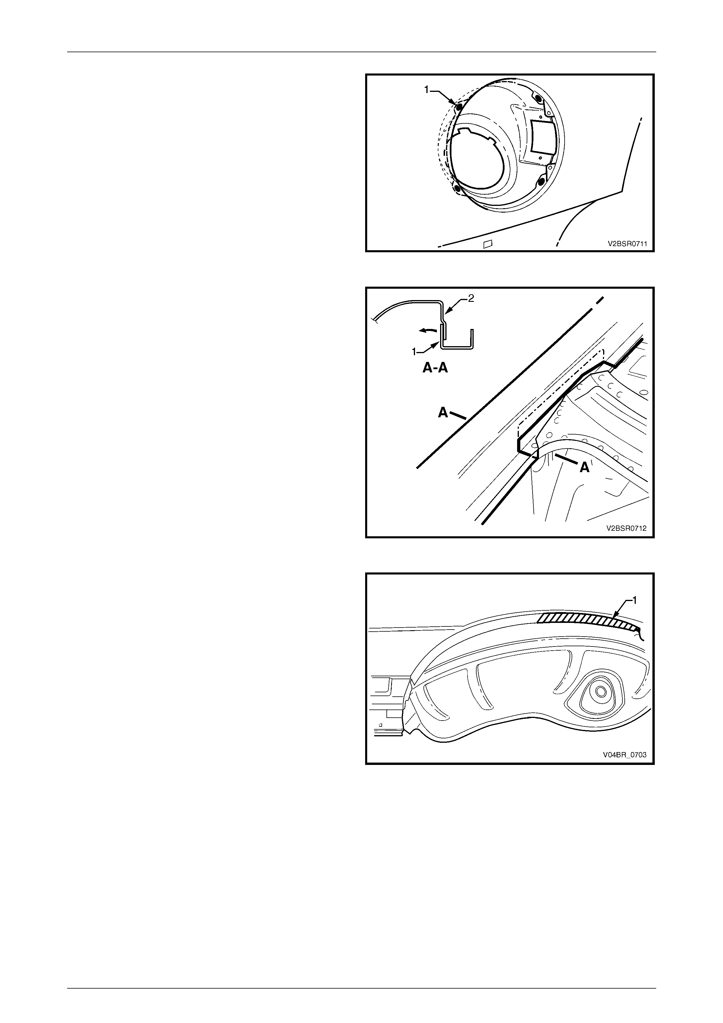
8 Spot cut the welds attaching the rear quarter panel to
the door opening frame assembly and quarter panel
inner assembly .
NOTE
If the roof panel has been removed, cut the
welds all the way along the quarter window
opening to the braze joint (1). Remove the three
welds attaching the rear quarter panel to the
body pillar inner panel reinforcement and using
an oxy / acetylene torch and wire brush, carefully
remove the brazing from the joint.
If the roof panel has not been removed, only
remove the spot welds as far as point (2). Mark a
line and cut the rear quarter panel at this area,
ensuring not to cut into the quarter panel inner
assembly.
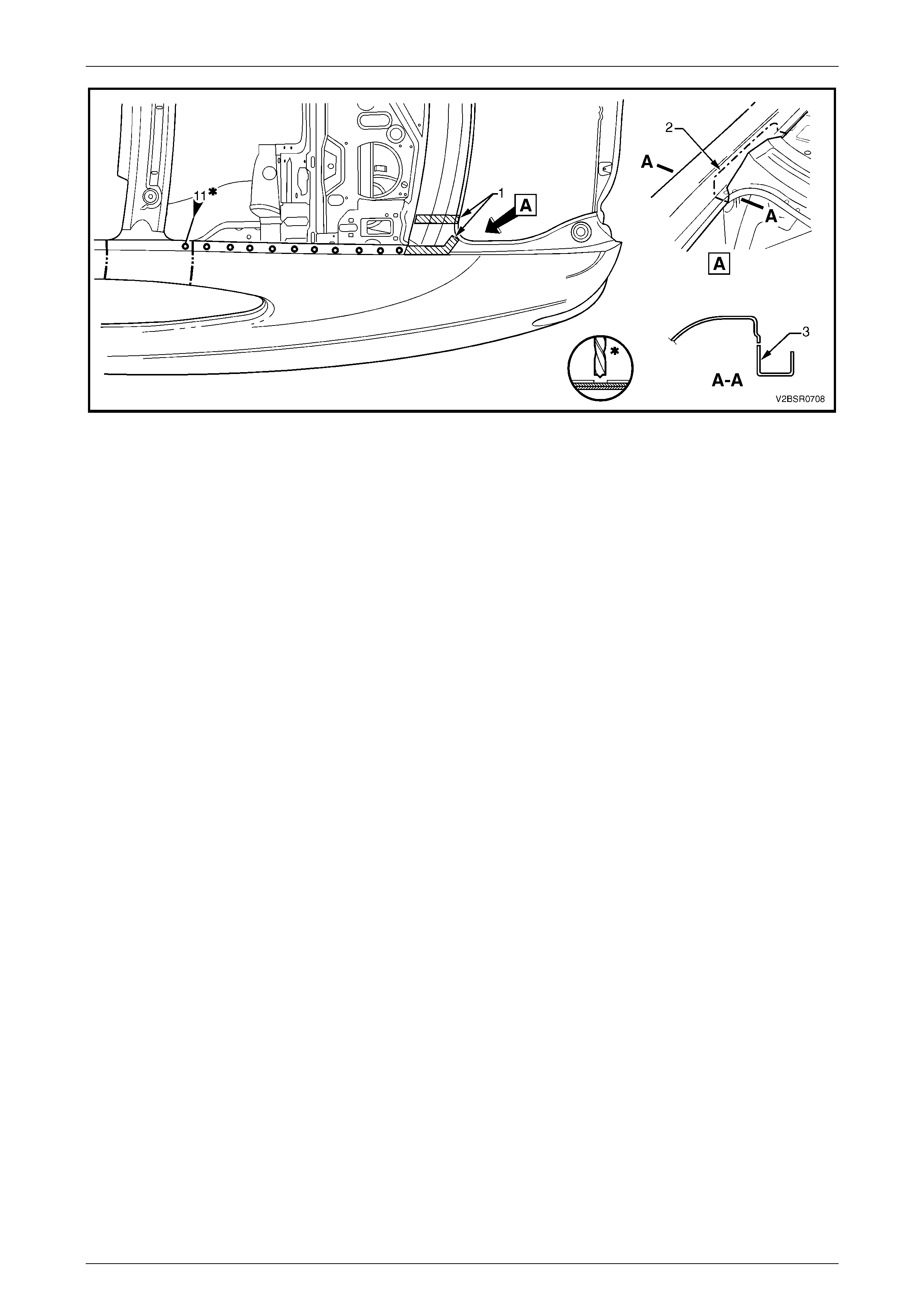
9 At the base of the lock pillar, the rear quarter panel is
sandwiched between the quarter inner panel assembly
and rear window panel assembly. Cutting the panel at
this point, as described below, rather than removing
extra panels, will save considerable time and effort as
structural adhesive (1) is used in this area, refer to
Figure 7 – 7.
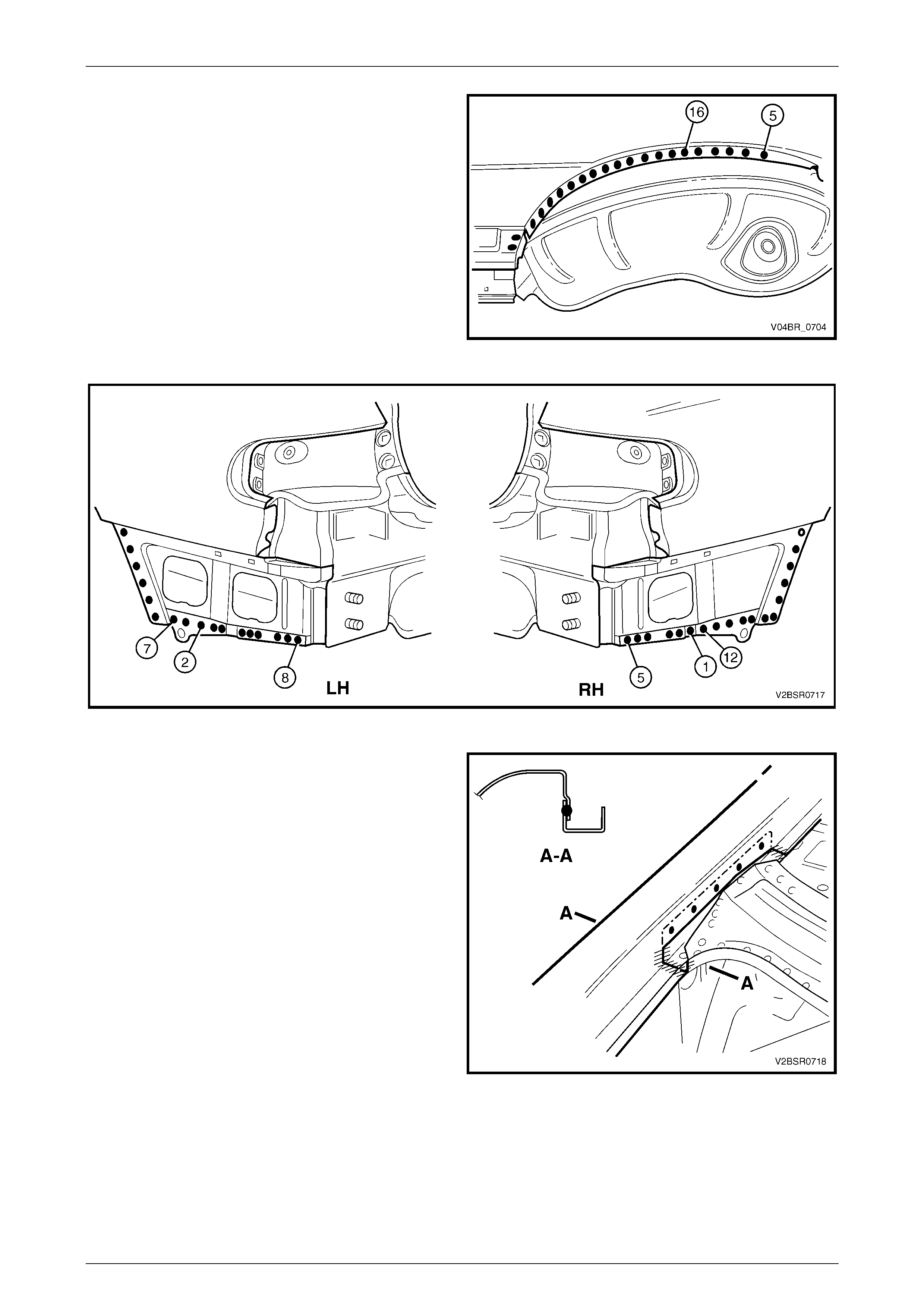
10 Using a saw or other appropriate equipment, cut
through the rear quarter panel as shown (2) at View A.
The cut should pass across the drain channel, then
along the inner face of the rear quarter panel.
NOTE
It is important to leave enough material (3) to
facilitate a lap joint of the old and new panels.
The drain channel and rear window opening
flange will be butt joined.
11 As required spot cut the welds attaching the rear
quarter panel to the quarter panel inner assembly.
Figure 7 – 6
Body Side Page 7–6
Page 7–6
Figure 7 – 7
12 Remove the panel from the vehicle and then repair any damage to adjacent parts.
NOTE
For the right-hand side, the fuel filler pipe housing
is attached to the quarter inner panel assembly
with acrylic spot weld sealer, which will require
separating while the panel is being removed.
13 Check and rectify the alignment of the body as required, refer to Section 3D, 3 Body Dimensions in the MY 2003
VY and V2 Series Service Information Supplement, Body Structure Repair.
Body Side Page 7–7
Page 7–7
Replace
NOTE
Spot welding is the preferred method for
attaching of panels and should be used whenever
possible. Where the spot welding equipment will
not access the required weld position, a plug
weld should be performed.
The same number and position of spot welds (or
plug welds) should be used when replacing the
panel, as was used during manufacture, in order
to maintain the original structural strength of the
vehicle.
1 On the replacement panel, remove the section (1) to
facilitate the join at the base of the lock pillar.
If surrounding panels have been replaced,
this section may be required to remain intact.
2 If the roof panel has not been removed, remove the
upper section of the lock pillar on the new panel to
match the removed panel.
Figure 7 – 8
3 From the scrap piece, manufacture a reinforcement (1)
to fit inside the remaining rear quarter panel on the
vehicle as shown.
NOTE
The reinforcement must not extend to the
flanges.
4 Mark the panel with drilling locations in preparation for
plug welding. Drill holes as required.
5 Prepare all mating surfaces an d treat w ith Weld
Through Primer (Item 1) as required, refer to
Section 3, 3 Body Sealing, Adhesives and Deadeners.
6 Clamp the reinforcement in position and plug weld it to
the vehicle.
Figure 7 – 9
Body Side Page 7–8
Page 7–8
7 For the right-hand side, if required spot or plug
weld (1) the fuel filler pipe housing to the rear quarter
panel in four places.
Figure 7 – 10
8 Open the flange (1) at the base of the lock pillar
outwards slightly to allow the new panel to seat
correctly.
9 As required, mark the new panel with drilling locations
in preparation for plug welding. Drill holes as required.
10 Prepare all mating surfaces an d treat w ith Weld
Through Primer (Item 1) as required, refer to
Section 3, 3 Body Sealing, Adhesives and Deadeners.
11 Apply Acrylic Spot Weld Sealer (Item 2), refer to
Section 3, 3 Body Sealing, Adhesives and Deadeners.
Figure 7 – 11
12 Apply Structural Adhesive (1) (Item 6), refer to
Section 3, 3 Body Sealing, Adhesives and Deadeners.
12 Clamp the rear quarter panel in position ensuring it is
seated correctly at the base of the lock pillar (2).
13 Test fit the alignment of the rear quarter panel with the
front door and rear compartment lid.
Figure SectNum – 12

Body Side Page 7–9
Page 7–9
14 Spot or plug weld the rear quarter panel to the quarter
panel inner assembly.
Figure 7 – 13
15 Spot or plug weld the rear quarter panel to the door
opening frame assembly and quarter panel inner
assembly.
NOTE
If the roof panel was removed, weld all the way
along the quarter window opening to the braze
joint (1). Plug weld the rear quarter panel to the
body pillar inner panel reinforcement and using
an oxy / acetylene torch, carefully braze weld the
joint.
If the roof panel was not removed, weld only as
far as point (2). Plug weld the rear quarter panel
to the manufactured reinforcement and using an
oxy / acetylene torch, carefully braze weld the
joint.
To reduce the risk of panel distortion, place
wet rags adjacent to the braze joints.
Figure 7 – 14
16 Spot or plug weld the rear quarter panel to the door
opening frame assembly.
Figure 7 – 15
Body Side Page 7–10
Page 7–10
17 Spot or plug weld the rear quarter panel to the door
opening frame assembly and rear quarter panel inner
assembly.
18 Spot or plug weld the rear quarter panel to the rear
quarter panel inner assembly and rear compartment
floor panel outer extension. There are a different
number of welds on the left-hand side to the right-hand
side, refer to Figure 7 – 17.
Figure 7 – 16
Figure 7 – 17
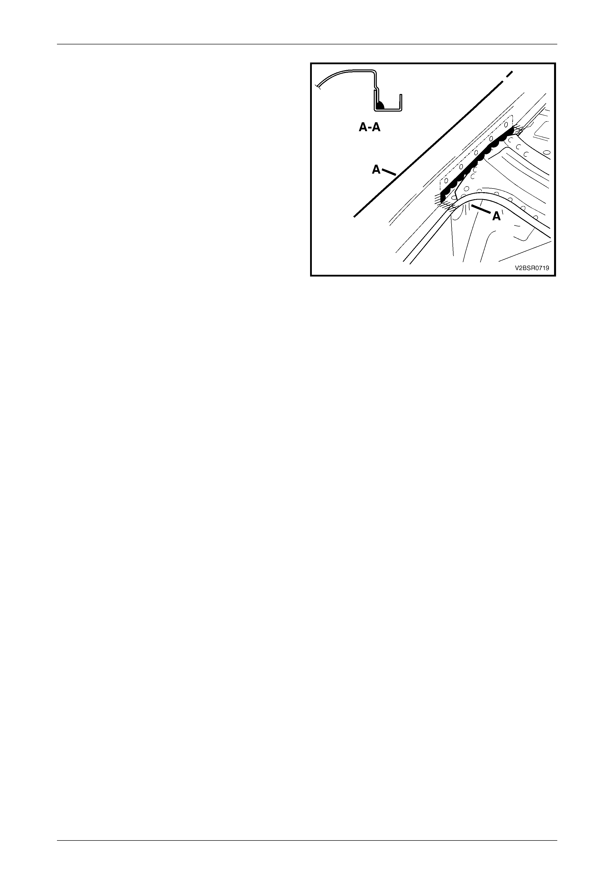
19 Spot or plug weld the rear quarter panel to the flange
at the base of the lock pillar and MIG butt weld across
the water channel and rear window flange.
20 Referring to 2.2 Tail Lamp Housing, Quarter Panel
Upper Extension and Quarter Panel Lower Extension
– Replace in the MY 2003 VY and V2 Series Service
Information Supplement, Body Structure Repair,
either:
• Install the tail lamp housing, quarter panel lower
extension and quarter panel upper extension, or
• Weld the rear quarter panel to these panels.
21 Refinish and paint panels and other components as
required. Refer to Section 3, 1.3 Paint Refinishing in
the MY 2003 VY and V2 Series Service Information
Supplement, Body Structure Repair.
22 Apply Joint Sealer (Item 3) as required, refer to
Section 3, 3 Body Sealing, Adhesives and Deadeners.
Figure 7 – 18
Body Side Page 7–11
Page 7–11
23 Add an additional bead of Joint Sealer to the lap joint
at the base of the lock pillar.
24 Apply Cavity Wax (Item 8) as required to the inside of
any box sections or areas inaccessible to paint, refer
Section 3D, 6 Cavity Wax in the MY 2003 VY and V2
Series Service Information Supplement, Body
Structure Repair.
25 Install rear bumper impact bar, refer to Section 3,
2 Bumper Impact Bar Assemblies in the MY 2003 VY
and V2 Series Service Information Supplement, Body
Structure Repair.
26 Insert Cavity Foam into the lock pillar as required,
refer to Section 2, 2.10 Cavity Foam in the MY 2003
VY and V2 Series Service Information Supplement,
Body Structure Repair.
27 Install the remaining components as described in the
MY 2004 VY and V2 Series Service Information.
Figure 7 – 19