
SECTION 2 - PRECAUTIONS
IMPORTANT
Before performing any Service Operation or other procedure described in this Section, refer to
Section 00 CAUTIONS AND NOTES in this Supplement for correct workshop practices with regard to
safety and/or property damage.
CAUTION
The body structure of MY2003 VY Series & V2 Series II vehicles has been developed using complex
design and development techniques. In addition to meeting all required standards, the vehicle body is
also a critical part of the overall safety systems. It is therefore imperative the repair procedures
described herein are adhered to during all vehicle body repairs.
1. GENERAL DESCRIPTION
2. PERSONAL SAFETY PRECAUTIONS
2.1 PROTECTIVE GEAR
2.2 FLAMMABLE MATERIALS
2.3 FUEL TANK
2.4 WORKSHOP VENTILATION
2.5 WELDING PRECAUTIONS
2.6 VEHICLE STABILITY PRECAUTIONS
2.7 DASH PANEL ADHESIVE
2.8 AIR CONDITIONING SYSTEM
3. GENERAL PRECAUTIONS
3.1 CUTTING LOCATIONS
3.2 DASH PANEL ASSEMBLY
3.3 STEERING SYSTEM
3.4 DISCHARGING THE FUEL LINES
4. OCCUPANT PROTECTION SYSTEM
PRECAUTIONS
4.1 REPAIRS TO VEHICLE STRUCTURE
4.2 REPAIRS & INSPECTIONS REQUIRED
AFTER A COLLISION
4.3 SYSTEM DISABLING & ENABLING
PROCEDURE
DISABLING THE OPS
ENABLING THE OPS
4.4 OPS SAFETY PRECAUTIONS
5. ELECTRICAL PRECAUTIONS
5.1 ELECTRONIC DEVICES
5.2 BEFORE REPAIRING THE VEHICLE
RADIO AND AUDIO EQUIPMENT
INSTRUMENTATION
CELLULAR MOBILE PHONES
PAINT OVEN
WELDING
5.3 LOCATION OF ELECTRONIC CONTROL
DEVICES
6. JACKING PRECAUTIONS
7. TOWING PRECAUTIONS
7.1 TOWING ON FOUR WHEELS
7.2 TOWING ON TWO WHEELS
8. PLASTIC COMPONENTS
8.1 PLASTIC COMPONENT PRECAUTIONS
8.2 PLASTIC COMPONENT IDENTIFICATION
9. SPECIAL STEEL PRECAUTIONS
9.1 PRE-COATED STEEL
9.2 RE-PHOSPHORISED STEEL
9.3 HIGH STRENGTH LOW ALLOY STEEL
10. CAVITY FOAM
SEDAN & WAGON
UTILITY
COUPE
10.1 CAVITY FOAM – REPLACE
HINGE PILLAR
CENTRE PILLAR, SEDAN & WAGON
CENTRE PILLAR, UTILITY
CENTRE PILLAR, COUPE
LOCK PILLAR, SEDAN
LOCK PILLAR, COUPE
11. LPG PRECAUTIONS
11.1 GENERAL SAFETY PRECAUTIONS
11.2 REPAIR WORK TO VEHICLE FITTED WITH LPG
DRAINING THE SERVICE LINES
LPG TANK REMOVAL

1. GENERAL DESCRI PTI O N
This Section contains important information regarding the precautions that are to be observed when performing
repair work on MY2003 VY Series & V2 Series II vehicles.
The reasons for thes e precautions are threef old. Firstly, it is important that the saf ety of thos e repairing the vehicle
is not com promised. Secondly, it m ust be ensured that inadvertent dam age is not caused to the vehicle during the
preparation for, or during the performance of, repairs to that vehicle. Finally, it must be ensured that any relevant
Federal and State legislation is abided by.
IMPORTANT: T his Section, along with Section 00 CAUT IONS & NOTES in the MY2003 VY Series & V2 Series II
Service Information should be thoroughly read and understood before any repair work is commenced on MY2003
VY Series & V2 Series II vehicles.

2. PERSONAL SAFETY PRECAUTIONS
2.1 PROTECTIVE GEAR
Protective clothing should be worn at all times when automotive body repair work is being carried out. The
appropriate safety gear will vary in accordance with the work being performed and includes:
Work overalls Work gloves Safety glasses
Dust mask Welding mask Leather apron
Safety shoes Ear muffs

2.2 FLAMMABLE MATERIALS
It is extremely important to keep the work areas clear of flammable materials. Flammable materials such as
adhesives, solvents and paints are regularly used in the repair industry. Their proximity creates a problem where
ignition sources such as grinding sparks and welding flames and sparks are regularly present.
All flammable chemicals should be kept in appropriate storage cabinets.
IMPORTANT: Be sure to abide by local laws and regulations regarding the storage of hazardous materials.

2.3 FUEL TANK
CAUTION: Keep all naked flames and sparks away from the vehicle if you can smell fuel vapour. Extreme
care must be exercised when using an oxy/acetylene torch.
Welding, grinding or drilling near the f uel tank is danger ous. If a vehicle has been involved in a collision, fuel may be
leaking from the tank, lines or unions.
If repairing the underbody, or any rear part of the vehicle, the fuel tank should first be removed to avoid fire and
possible personal injury.
Be aware that gr inding or cutting the f uel pipes may cause fire. For the proc edure to dis c harge the fuel lines ref er to
3.4 DISCHARGING THE FUEL LINES.

2.4 WORKSHOP VENTILATION
The repair of autom otive bodies involves grinding and s anding procedures that produce dust. Inhaling this dust may
be hazardous to health and steps should be taken to avoid inhalation. Adequate ventilation must be provided at all
times.
In addition, some paints and sealants produce toxic gas when ignited. Appropriate breathing apparatus should be
worn for protection, in addition to keeping the work environment well ventilated.

2.5 WELDING PRECAUTIONS
The process of welding produces fumes which if inhaled may have short or long term health effects.
Welding metals containing certain alloys, are galvanised or are specially treated may increase the health risk.
While the risk s to the body repairer are s light, it is imperative that any welding is performed in a well-ventilated area.
Where it is not possible to ensure good ventilation, a suitable respirator should be worn.
The body structure of MY2003 VY Series & V2 Series II vehicles consists of metal components made from:
• Mild steel,
• Mild steel with Galvaneal coating – 2 sides,
• Mild steel with Zinc coating – 2 sides,
• Mild steel with Zinc-nickel coating – 1 & 2 sides.

2.6 VEHICLE STABILITY PRECAUTIONS
To avoid personal injury occurring, the following precautions should be observed:
• Secure the vehicle on safety stands; never work below a vehicle supported only by jacks.
• Frame straightening equipment can be dangerous; always use in strict accordance with the manufacturer’s
recommendations.

2.7 DASH PANEL ADHESIVE
The silicone adhesive used in the glue track, once cured, requires no special precautions. However, when mixing
the adhesive compound with the catalyst, the precautions listed below should be observed.
• The catalyst is a toxic substance and must not be swallowed. Keep the catalyst out of reach of children.
• Wear saf ety glasses to avoid contact with the eyes. If eye contact occurs, wash the ar ea in clean water only, and
seek immediate medical advice.
• Wear protective gloves when handing the adhesive and catalyst as they can cause skin irritation.
• If irritation occurs , wipe the adhesive/catalys t off us ing a clean cloth and then wash the aff ected area thoroughly
in clean water.
• As the vapour produced by the catalyst may cause breathing difficulties, use only in a well ventilated area.
• Since the catalyst is combustible, keep it away from sparks and flame.

2.8 AIR CONDITIONING S YSTEM
NOTE: As an environmental measure, Federal and State legislation requires air-conditioning systems be
discharged in accordance with certain regulations. It is recommended that you be acquainted with the requirements.
Care should be tak en when discharging the air conditioning system to ensure that the refriger ant is not released to
the atmosphere, but recaptured for recycling. Environment friendly refrigerant R134a is not an ozone depleting
substance but its release would add to the greenhouse warming effect. It is therefore essential that the refrigerant
be recovered using a Refrigerant Recovery Unit (RRU).
Refer to Section 2C AIR CONDIT IONING – SERVICING AND DIAGNOSIS in the MY2003 VY Series & V2 Series
II Service Information for comprehensive procedures on discharging and refilling the air conditioning system.
NOTE: R134a and R12 are not compatible and must never be mixed.
Frostbite will be c aused if the r efriger ant liquid contacts sk in. Always wear safety gloves and goggles and stay clear
of any discharge.
If R134a enters the eye, freezing of the eye could occur and could result in blindness. If this situation occurs, the
following procedure is suggested:
1. Keep calm.
2. Do not rub eyes.
3. Splash large quantities of cool water into the eyes to raise the temperature.
4. Tape a sterile patch in place to prevent dirt from entering the eye.
5. Go immediately to a doctor or hospital.
CAUTION: Do not attempt to treat the condition yourself.

3. GENERAL PRECAUTIONS
3.1 CUTTING LOCATIONS
CAUTION: Do not cut the body structure at any point other than specified in this Supplement.
The MY2003 VY Series & V2 Series II vehic le body structures are des igned to meet or ex c eed all relevant Statutor y
Regulations. Cutting anywhere other than specified may compromise the strength of the vehicle and therefore
occupant protection system operation and occupant safety.

3.2 DASH PANEL ASSEMBLY
CAUTION: To avoid fire, do not attempt to burn the remaining sealant from the glue track using an “oxy”
torch.
The dash panel assembly must be bonded to the body with the correct two-part, fast cure silicone adhesive. It is
important that the dash panel is ready for installation and has been trial fitted before the adhesive is mixed, as the
working time is less than 20 minutes.
Ensure that prepar ation of the panel sur face is com pleted pr ior to m ixing the adhesive. T his should include painting
of the surrounding areas and thorough cleaning of the glue track.
After installation, the dash panel should not be disturbed until the adhesive is fully cured (about 3 hours).
Refer to Section 5, COCKPIT MODULE for a full description of the installation procedure for the dash panel
assembly.

3.3 STEERING SYSTEM
Vehicles involved in collisions resulting in major body or sheet metal damage, or where the steering column has
been impacted, may also have a damaged or misaligned steering column. Refer to Section 9A, STEERING –
Checking Steering Column For Accident Damage, in the MY2003 VY Series & V2 Series II Service Information.

3.4 DISCHARGING THE FUEL LINES
CAUTION: The fuel rail on the engine may contain up to one litre of fuel under pressure. Disconnecting the
fuel lines at any point without relieving the pressure w ill cause petrol to be expelled and may cause fire or
injury.
To discharge the fuel lines:
1. Apply the parking brake.
2. Remove the Fuel Pump fuse from the engine compartment fuse and relay panel.
3. With the throttle closed, crank the engine.
NOTE: The engine may start and idle, until the fuel supply remaining in the lines is exhausted.
4. When the engine stops, engage the starter again for a further 10 seconds to ensure dissipation of any
remaining pressure.
5. Turn the ignition switch to the OFF position.
6. Disconnect the fuel lines from the fuel tank, allowing any remaining fuel to drain, and then seal the apertures
with suitable plastic plugs.
7. Drain the contents of the fuel tank.
NOTE: The fuel tank may contain up to 82 litres of petrol.
9. Remove the tank from the vehicle, refer to Sect ion 8A1, FUEL T ANK in the MY2003 VY Series & V2 Ser ies II
Service Information.
10. Seal the fuel tank filler with a plug. Do not use a rag.
4. OCCUPANT PROTECTION SYSTEM PRECAUTI ONS
The Occupant Protection System (OPS) fitted to MY2003 VY Series & V2 Series II vehicles provides protection
additional to the driver and front passenger seatbelts in three ways:
1. By activating seatbelt pretensioners which tighten the seatbelt slightly during a collision, restricting the
occupant’s forward movement,
2. By deploying a front driver inflatable restraint from the centre of the steering wheel and a front passenger
inflatable restraint (where fitted) from the top left side of the instrument panel pad assembly, during certain
frontal collisions,
3. By deploying a side inflatable res traint (where fitted) for the fr ont occupants to of fer additional protec tion for the
driver or front passenger during certain side impact collisions.
The Sensing and Diagnostic Module (SDM), located under the front floor console, controls inflatable restraint and
seatbelt pretensioner deployment. The SDM has the ability to deploy the seatbelt pretensioners only, the
pretensioners and front inflatable restraint or a side inflatable restraint on the side of the vehicle, which an impact
occurs.
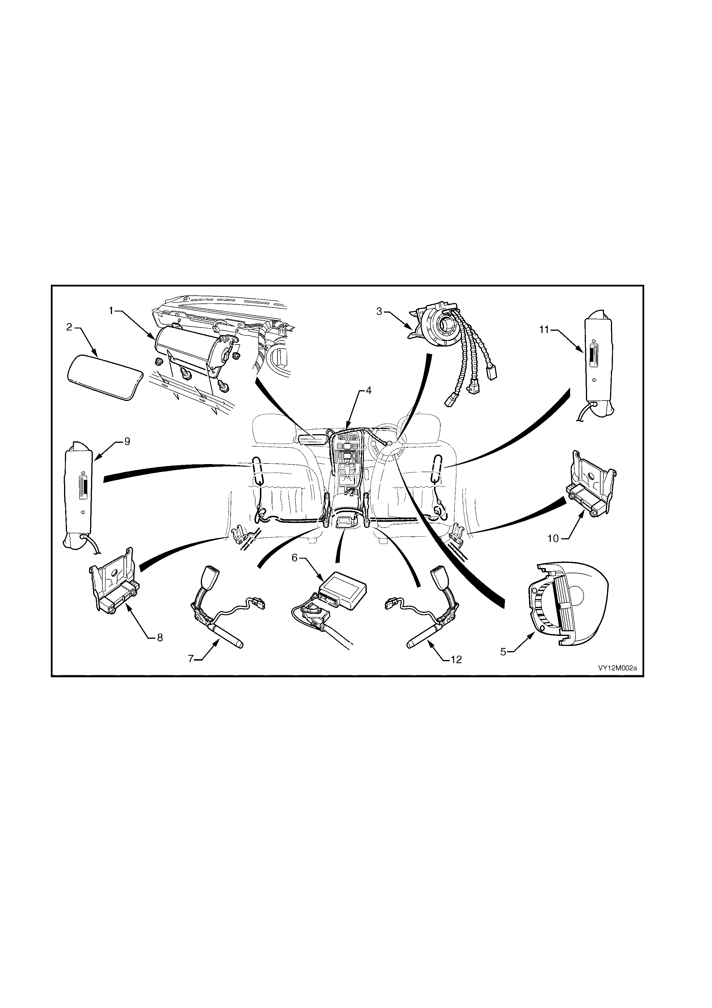
Refer to Figure 2-1 for occupant protection system component locations.
Figure 2-1
Legend
1. Front Passenger Inflatable Restrai nt Ass embly
2. Inst rument Panel Inflatabl e Restraint Openi ng Tri m Cover
3. Clock Spring Coil A ssem bl y
4. Wiring Harnes s (part of main wiring harness)
5. Driver Inflatable Restrai nt Ass e mbly
6. Sensing and Di agnostic Module (S DM)
7. Left-Si de S eatbelt Pret ensioner Assembly
8. Left Impact Sensor
9. Left-Si de Inflatable Restraint Assembly
10. Right I mpact Sensor
11. Right-S i de Inflatabl e Restraint Assembly
12. Right-S i de Seatbelt P retensioner Assem bl y
IMPORTANT:
• Accessory type or after-market bull-bars or such devices not approved and fitted to a vehicle with OPS may
adversely affect the vehicle’s desired threshold characteristics for deployment.
• Accessory and after-market seat covers must not be fitted to a vehicle with side inflatable restraints unless
approved by the vehicle manufac turer. Seat c overs that are not approved could gr eatly inhibit the perfor mance
of the side inflatable restraint, compromising the occupant’s safety in the event of side inflatable restraint
deployment.

• Accessory or after-m arket instrument panel covers, or the like, m ust not be installed. This would greatly inhibit
the performance of the front passenger inflatable restraint and reduce front passenger’s safety in the event of
an inflatable restraint deploy ment.
• Fitting of accessories such as drink holders, cassette / CD racks, additional mirrors, etc. are not permitted in the
imm ediate deployment ar ea of the front passenger ’s inflatable restraint as these may be propelled towards the
occupants when the airbag is deployed.

4.1 REPAIRS TO VEHICLE STRUCTURE
CAUTION: Correct operation of the Occupant Protection System (OPS) requires that any repairs to the
vehicle structure must return it to its original production configuration.
The procedures to achieve this are in line with those detailed in the relevant Section of this Supplement.
The integrity of the front side rail assemblies is critical to the function of the OPS. If the front side rail assemblies are
damaged, or incorr ectly repaired following dam age, it is pos sible the OPS will not function as intended, res ulting in
incorrect deployment timing and placing the occupant(s) at increased risk of injury.
The following strategy should be used when repairing the front side rail assemblies.
1. If minor damage has occurred to the front of the front side rail assembly which does not involve significant
creasing or crumple, it may be straightened.
2. If significant creasing or crumple of the front side rail assembly has occurred, but is restricted to the area
forward of the front suspension crossmember, the front side rail assembly may be cut at a point between the
two crossmember mounting bolts and a new partial section welded in place. For information on the
recommended cut point, refer to Section 4, FRONT END.
3. If significant creasing or crumple of the front side rail assembly has occurred and continues rearward of the
front of the front suspension crossmember, the full front side rail assembly should be replaced.

4.2 REPAIRS AND INSPECTIONS REQUIRED AFTER A COLLISION
The following table lists the components that must be replaces if deployment occurs under the conditions listed. If
any SRS c omponents ar e damaged, they must be r eplaced with new parts. If OPS com ponent m ounting points are
damaged, they must be repaired or replaced.
NOTE: Never use OPS components from another vehicle.
The steering wheel must be dimensionally inspected, whether deployment has occurred or not. Refer to
Section 9A, STEERING – Check ing Steering Colum n for Ac cident Damage, in the MY2003 VY Series & V2 Series
II Service Information.
A COLLISION SEVERE ENOUGH TO DEPLOY THE SEATBELT PRETENSIONERS BUT NOT THE
INFLATABLE RESTRAINTS(S).
Replace the following components:
• Any seatbelt worn during the collision,
• Seatbelt pretensioner/s,
• Front seat guide rail and adjuster assembly (where the seat was occupied in the collision),
• Sensing and Diagnostic Module.
A COLLISION WHERE THE SEATBELT PRETENSIONERS AND FRONT INFLATABLE RESTRAINT(S) HAS
DEPLOYED.
Replace the components as above in addition to:
• Driver inflatable restraint module,
• Steering wheel,
• Clock spring coil,
• Steering column,
• Instrument panel inflatable restraint module (where fitted),
• Instrument panel pad assembly,
• Instrument panel inflatable restraint opening trim cover,
• Instrument panel inflatable restraint bracket,
• Instrument panel lower bracket.
A COLLISION WHERE A SIDE INFLATABLE RESTRAINT HAS DEPLOYED.
Replace the following components:
• Any seatbelt worn during the collision,
• Relevant side front seat assembly (including the side inflatable restraint module),
• Relevant side impact sensor,
• Sensing and Diagnostic Module.

4.3 SYSTEM DISABLING & ENABLING PROCEDURE
DISABLING THE OPS
CAUTION: The SDM can maintain sufficient voltage to cause SRS deployment for up to 10 seconds after
the ignition switch is turned OFF or the battery is disconnected.
1. Disconnect both the batter y earth and power leads, wait at least 10 seconds before performing any work on the
vehicle.
NOTE: Disconnection of the battery affects certain vehicle electronic systems. Refer to Section 00, 5. BATTERY
DISCONNECTION PROCEDURES before disconnecting the battery.
ENABLING THE OPS
NOTE: Ensure all wiring harness connectors are connected before reconnecting the battery leads.
1. Reconnect both the battery power and earth leads.
2. Switch ignition ON and observe the OPS (SRS) warning indicator in the instrument cluster. The warning
indicator should be illuminated for approximately five seconds. During this period the SDM performs a wiring
and self-check.
3. If no system faults are detected, the warning indicator will be switched off. If the warning indicator remains
illuminated and an audible alar m c himes , or the warning indicator illum inates two seconds after it was originally
switched off, an OPS fault is present. Refer to Section 12M, OCCUPANT PROTECTION SYSTEM -
DIAGNOSTICS in the MY2003 VY Series & V2 Series II Service Information.

4.4 OPS SAFETY PRECAUTIONS
• Do not use a fast battery charger for starting the vehicle.
• Never disconnect the battery from the vehicle’s electrical system while the engine is running.
• Disconnect the battery from the vehicle’s electrical system before fast battery charging.
• Never disconnect or connect the SDM connector with the ignition turned on.
• After an accident, always replace the individual OPS com ponents. Refer to 4.2 REPAIRS AND INSPECTI ONS
REQUIRED AFTER A COLLISION in this Section.
NOTE: Damaged or defective components must always be replaced with new parts.
• Always reinstall fasteners in the same location from which they were removed, using the correct tightening
torque where given. If the fastener needs replacing, replace it with the correct part number.
• Because the strength of the windshield and its urethane adhesive is critical to the correct deployment
of the airbag, always replace these items with parts complying to the correct specification, refer to
Section 1A6 STATIONARY WINDOWS in the MY2003 VY Series & V2 Series II Service information.
Failure to use the c orrect product m ay res ult in poor retention of the glass. For vehicles with a front pass enger
airbag, the windshield must be replaced correctly to ensure the occupant protection provided by the OPS is
maintained as the windshield supports the passenger airbag during deployment.
• Take c are when handling the side impact sens or. Never strik e or jar the sensor or adjacent body st ructure in a
manner which could cause deployment of the side airbag. Never carry a peripheral acceleration sensor by the
wiring harness leads.
If a peripheral acceleration sensor is dropped from a height greater than one metre, it must be replaced.
• Take c are when handling the SDM. Never strik e or j ar the m odule or body struc ture adjacent to the module in a
manner which could cause deployment of the pretensioners or inflatable restraints.
• When c ar rying a live (undeployed) inf latable res tr aint module, ens ur e that it is always pointed away from you. In
case of an accidental deployment, the likelihood of injury from the airbag is minimised.
• W hen placing a live inflatable res traint module on a bench or other surf ace, always face the assembly up. T his
will provide f ree s pace f or the inflatable rest raint to expand in case of accidental deployment. Also, never place
anything on top of the inflatable restraint module.
• Never carry the pretens ioners, driver ’s inf latable r estraint module, f ront pass enger inf latable restr aint m odule or
side inflatable restraints module by their wiring harness leads.
• Do not apply power to a module except as specified in the MY2003 VY Series & V2 Series II Service
Information.
• Do not attempt to m ake any repairs or modifications to a module or sensor. A dam aged or defective horn bar
and driver airbag inflator module, front passenger airbag inflator module or side airbag inflator module must
only be replaced with new parts.
• Always wear gloves and safety glasses when handling a deployed pretensioner or inflatable restraint module.
The surface of these components may contain chemicals (e.g. sodium hydroxide) as a result of the gas
generated during combustion. This can irritate the skin. Wash hands with mild soap and water after handling.
• Refer to Section 12M, OCCUPANT PROTECTION SYSTEM in the MY2003 VY Series & V2 Series II Service
Information for detailed service procedures and precautions.

5. ELECTRICAL PRECAUTIONS
5.1 ELECTRONIC DEVICES
MY2003 VY Series & V2 Series II vehicles are equipped with many electronic devices as standard equipment to
monitor and control various vehicle functions.
These electronic devices are susceptible to damage from severe shock, transient voltage and high temperatures.
IMPORTANT: Par tic ular note s hould be taken of the Powertrain Control Module ( PCM), which is loc ated on the lef t-
hand hinge pillar panel. Heat, or transient voltage produced by spot, MIG or arc welding techniques will cause
damage to the electrical components within the PCM. Always disconnect the battery and unplug and remove the
PCM before repairing the vehicle.
It is worth noting that other equipment, such as instruments, radios, mobile telephones and various
afterm ark et access ories are also c ontrolled by elec tronics and are ther efore subj ect to similar prec autions. Refer to
Figures 2-2 – 2-6 for the electronic devices and their locations.

5.2 BEFORE REPAIRING THE VEHICLE
1. Disconnect both the negative and positive cables from the battery terminals.
IMPORTANT: Disconnection of the battery affects certain vehicle electronic systems. Refer to Section 00,
5. BATTERY DISCONNECTION PROCEDURES in the MY 2003 VY & V2 Series II Service Information before
disconnecting the battery.
2. Unplug the harnesses and remove the PCM from the left side hinge pillar panel.
3. Check the area adjacent to the damage for electronic devices, particularly behind trim panels and under the
dashboard.
4. Remove any units that may have been damaged in the impact or may be damaged during repairs.
RADIO A ND AUDIO EQUIPMENT
Radios and other forms of audio equipment should be treated with due care. Before removing the equipment or
com m encing repairs to the vehicle, cons ult the radio operator ’s m anual acc om panying the vehicle for precautionar y
details. Always disconnect both the negative and positive cables from the battery terminals. Never have the radio
operating while repairing the vehicle.
IMPORTANT: As a thef t deterrent, all vehic les are f itted with a security coded audio syst em . After the power s upply
is interrupted, the radio will remain inoperative after reinstallation until the PIN number is entered into the system.
The procedure is described in the instructions accompanying the radio.
INSTRUMENTATION
The instruments can be damaged by impact, or temperatures above 80°C. Always remove the instrument cluster
before subjecting the vehicle to temperatures above 80°C.
CELLULAR MOBILE PHONES
Transient voltage and magnetic pulses can easily damage mobile phones and other communications equipment.
Such comm unications equipm ent sometimes has the control unit m ounted in the luggage compartm ent or in other
out of sight areas. Refer to the operator’s instructions accompanying the particular unit for precautions.
PAINT OVENS
The high tem peratures produced in a paint oven can dam age the electronic control devices and some tr im item s in
the vehicle.
NOTE: Remove all electronic devices, plastic or fabric trim items and the dashboard assembly, before placing the
vehicle in a paint oven that will achieve temperatures above 70°C.
WELDING
MIG or arc welding pr oduc es tr ans ient voltages that may damage the electr onic c ontrol devic es unless the f ollowing
precautions are observed:
1. Always disconnect both terminals of the battery and remove the Powertrain Control Module (PCM) before
repairing any part of the vehicle.
2. Ensure that the earth clamp is located as close as possible to the welding site.
3. Check behind the panels being welded for wiring harnesses. Reposition any harness to avoid damage.
4. In the vicinity of the repairs, disconnect the wiring harness Body Earth Points.
5. Remove any electronic control devices from areas near the damage, refer to Figures 2-2 – 2.6.
5.3 LOCATION OF ELECTRONIC CONTROL DEVICES
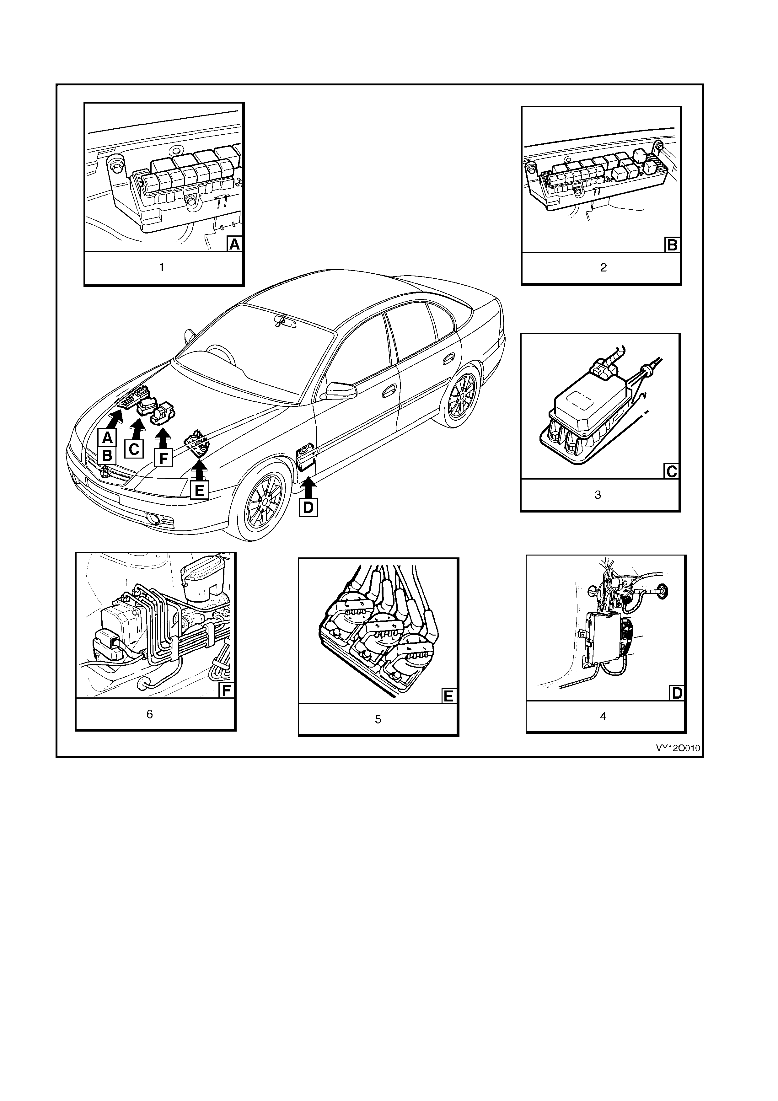
Figure 2-2
Legend
1. Fusible Links
2. Fuse and Relay Panel
3. Cruise Control Module
4. Powertrain Interfac e Module (P IM) – V6 Engines
5. Direct Ignition Syst em (DIS ) Module – V 6 E ngi nes
6. ABS Hydraulic Modulator
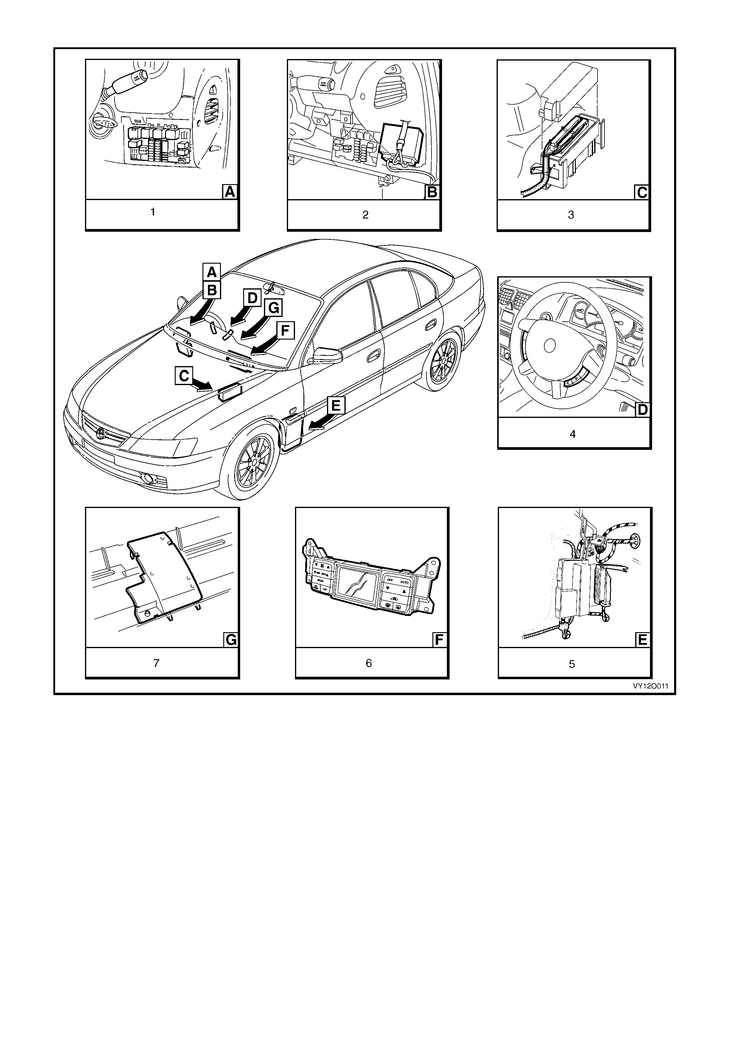
Figure 2-3
Legend
1. Relays & Fuses – Instrument Panel
2. Body Control Module
3. Powertrain Control Module – Gen III V8
4. Steering Wheel Radio & CD Player Control s
5. Powertrain Interfac e Module (P IM) – GEN III V 8 Engine
6. Climate Control Module
7. Ambient Li ght Sensor
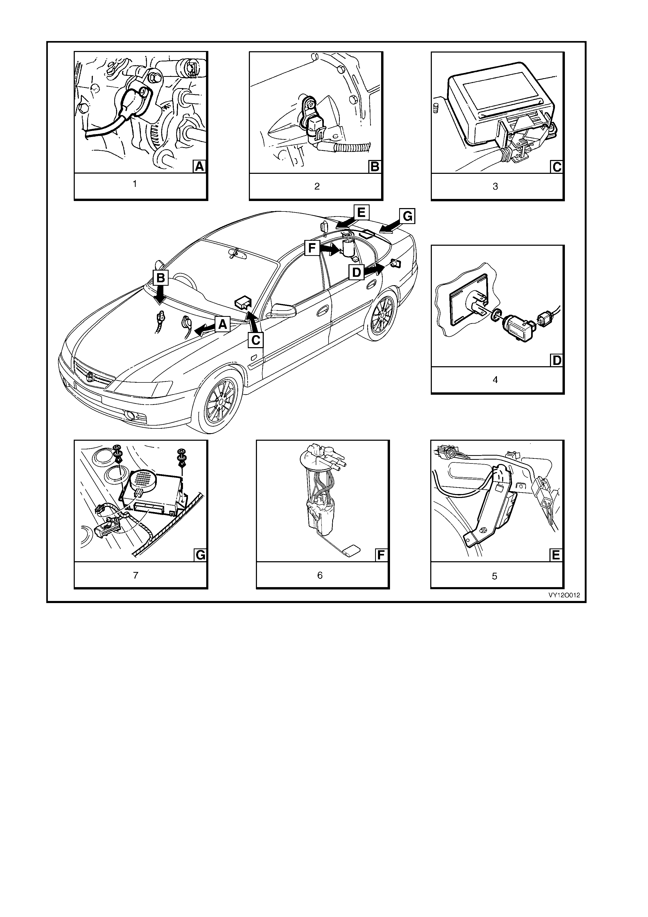
Figure 2-4
Legend
1. Vehicle Speed Sensor – Manual Transmission (V6 Shown,
V8 Similar).
2. Vehicle Speed Sensor – Automatic Trans mission
3. Sensing & Diagnosti c Module – Occupant Protecti on System
4. Rear Object Sens or A ssembly
5. Fuel Pump Control Module – V 6 Supercharged Engine
6. Modular Fuel Pump and Sender A ssem bl y
7. Rear Object Sens or Cont rol Module
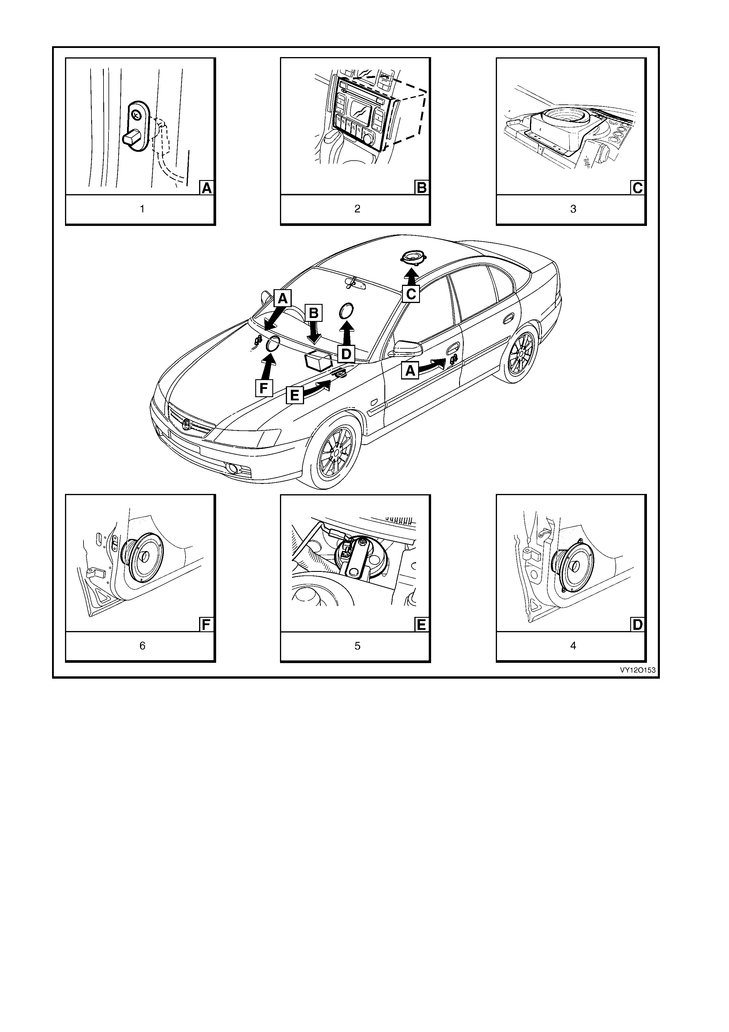
Figure 2-5
Legend
1. Door Ajar Warning Switch
2. Radio Assembly
3. Rear Speaker (2 Places)
4. Front Door Speaker As sembl y (2 Pl aces)
5. Anti-theft Horn
6. Rear Door Speaker Assembly (2 P l aces)

Figure 2-6
Legend
1. Navigation System Assembly
2. Telematics Antenna
3. Rear View Mirror A ssem bl y with Telematics
4. Telematics Control Module
5. Navigation System Speaker
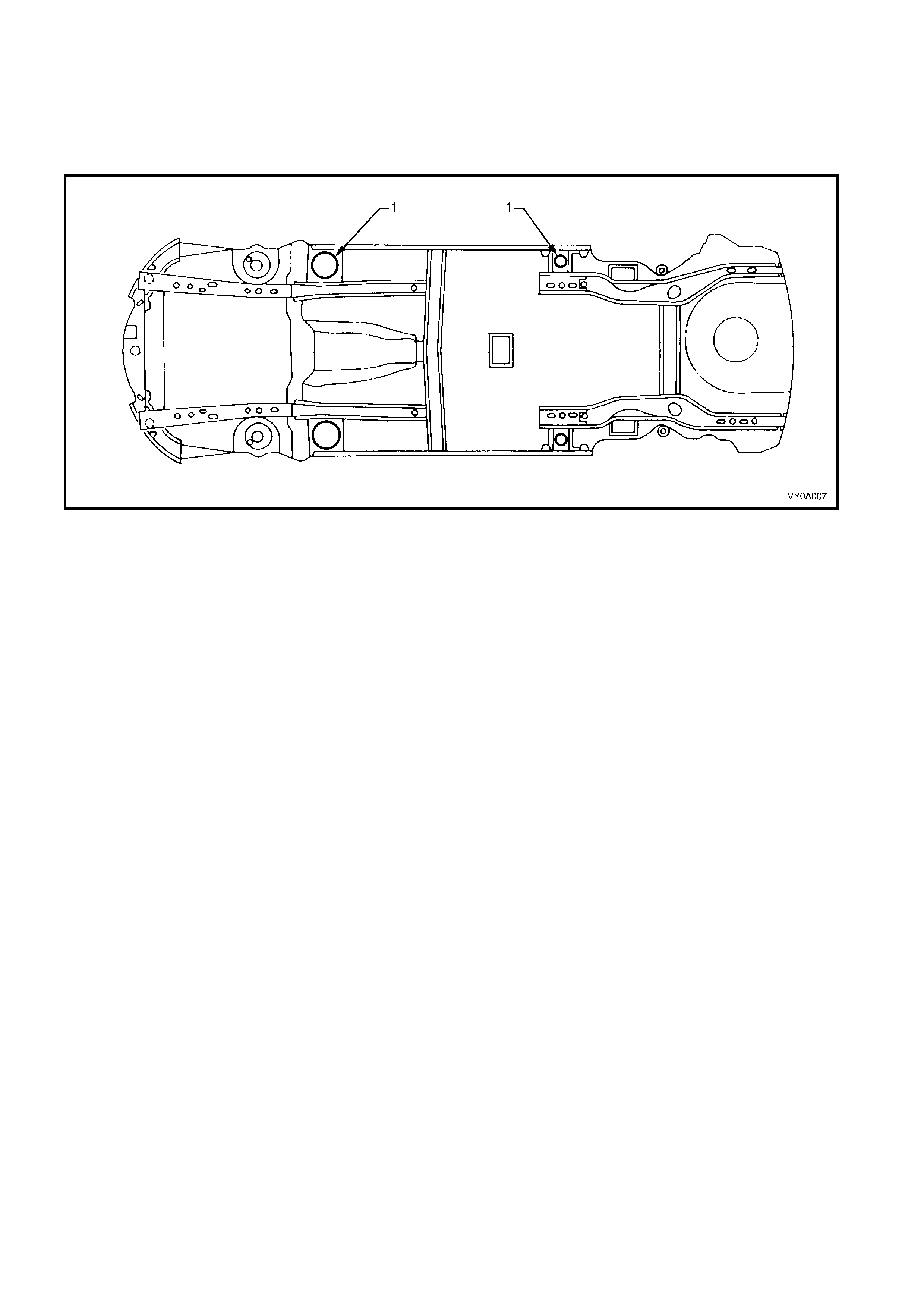
6. JACKING PRECAUTIONS
NOTE: When using a trolley jack to raise the vehicle, it is important that the jack be positioned under the
suspension crossmember or hoist pad locations (1). Refer to Figure 2-7.
Do not j ack under the sus pension c ontrol arm s . The vehic le should always be supported by j ack stands at the hoist
pad locations when raised.
Figure 2-7

7. TOWING PRECAUTIONS
The c orrec t lifting or towing equipm ent is nec essar y when lif ting or towing the vehicle to prevent dam age during any
towing operation.
IMPORTANT: Towing the vehicle is the sole responsibility of the individual tow truck operator and is at his/her
discretion as to the appropriate method of towing a vehicle in each instance. State and Local laws must be obeyed
at all times.
7.1 TOWING ON FOUR WHEELS
The vehicle may be towed on all four wheels taking note of the following precautions:
• Switch the ignition key to the ACC position to free the steering lock.
• Ensure that the transmission (Manual or Automatic) is in Neutral position.
• Remove the propeller shaft if the transmission is damaged.
NOTE 1: Vehicles fitted with automatic transmission must not be towed at a speed over 55 km/h unless the
propeller shaft is removed.
NOTE 2: Do not attach towing equipment to the bumper bars or brackets.
IMPORTANT: Only one person (to steer the vehicle) is permitted in the towed vehicle; passengers are not allowed.

7.2 TOWING ON TWO WHEELS
The vehicle may be towed with two wheels off the ground under the following conditions:
• If towing the vehicle from the rear, do not use the steering lock to lock the front wheels in the straight ahead
position. T he st eering loc k m us t be f r ee, as the st eering loc k m ec hanis m and ignition switch may be dam aged if
used to prevent the steer ing fr om m oving while towing. Use other appropriate means of sec uring the steering in
the straight ahead position.
• Take care not to foul the brake pipes. Do not use suspension components as lifting points.
• Ensure the transmission (Manual or Automatic) is in the Neutral position.
• Remove the propeller shaft if the transmission is damaged and the vehicle is being towed on the rear wheels.
NOTE: Vehicles fitted with automatic transmission must not be towed on the rear wheels at a speed over 55 k m/h
unless the propeller shaft is removed.

8. PLASTI C COMPONENTS
8.1 PLASTIC COMPONENT PRECAUTIONS
Plastic components are used throughout the vehicle. The following chart is included to assist with the
characteristics and precautions to be taken with the most common types. The repair procedure for plastic
body parts must conform with the type of plastic material.
Refer to 8.2 PLASTIC COMPONENT IDENTIFICATION for a listing of the main plastic components used
throughout the vehicle and the material from which they are made.
Code Material
Name Heat Resisting
Temp* °C Resistance to
Alcohol or Gasoline Notes
ABS Acrylonitrile
Butadiene
Styrene Resin
80 Alcohol is harmless if applied only
for short time in small amounts (i.e.
quick wiping to remove grease)
Avoid gasoline and
organic or aromatic
solvents.
ASA Acrylate
Styrene
Acrylonitrile
80 Alcohol is harmless if applied only
for short time in small amounts (i.e.
quick wiping to remove grease)
Avoid gasoline and
organic or aromatic
solvents.
PC Polycarbonate 120 Alcohol is harmless. Avoid gasoline, brake
fluid, wax, wax removers
and organic solvents.
PMMA Polymethyl
Methacrylate 80 Alcohol is harmless if applied only
for short time in small amounts. Avoid dipping or
immersing in alcohol,
gasoline, solvents, etc.
PE Polyethylene 80 Alcohol and gasoline are harmless. Most solvents are
harmless.
PP /
PP67 Polypropylene 80 Alcohol and gasoline are harmless. Most solvents are
harmless.
PPE Polyphenylene
Ether 100 Alcohol and gasoline are harmless
if applied only for a short time in
small amounts (i.e. quick wiping to
remove grease)
Avoid dipping or
immersing in alcohol,
gasoline, solvents, etc.
PU Polyurethane
Foam 100 Alcohol and gasoline are harmless
if applied only for a short time in
small amounts (i.e. quick wiping to
remove grease)
Avoid dipping or
immersing in alcohol,
gasoline, solvents, etc.
PVC Polyvinyl
Chloride 80 Alcohol and gasoline are harmless
if applied only for short time in small
amounts. (i.e. quick wiping to
remove grease)
Avoid dipping or
immersing in alcohol,
gasoline, solvents, etc.
TPO Thermoplastic
Olefin 80 Alcohol is harmless.
Gasoline is harmless if applied only
for short time in small amounts.
Most solvents are
harmless but avoid
dipping or immersing in
alcohol, gasoline,
solvents, etc.
PPE/
PA-M20 Modified
Poly propylene
Ether &
Poly amide
Alloy
190 Alcohol and gasoline are harmless
if applied only for a short time in
small amounts (i.e. quick wiping to
remove grease)
Avoid dipping or
immersing in alcohol,
gasoline, solvents, etc.
∗ Temperatures higher than those listed here may result in material deformation.
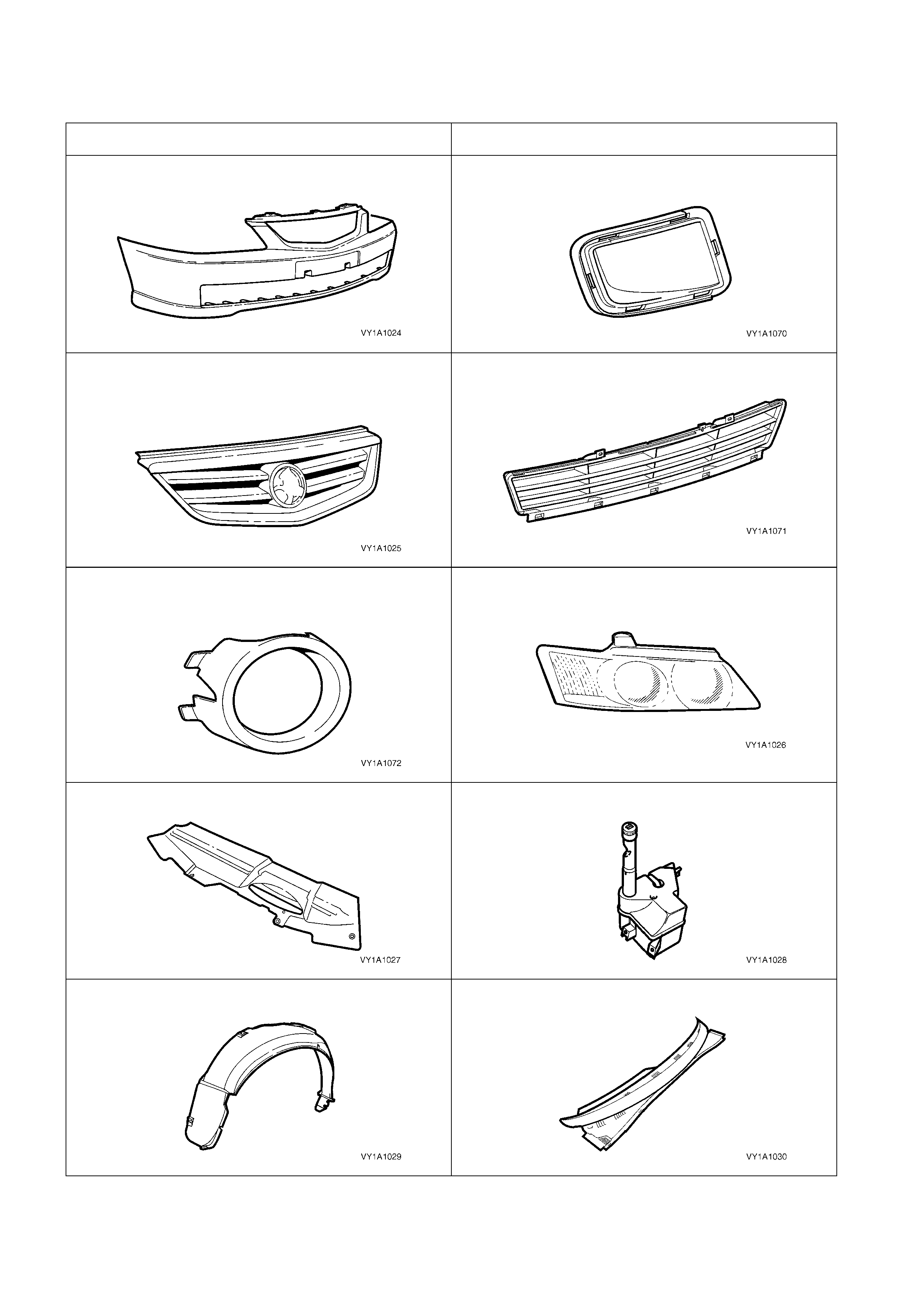
8.2 PLASTIC COMPONENT IDENTIFICATION
NOTE: Most components are also identified with the material code in an inconspicuous place.
EXTERIOR / ENGINE COMPARTMENT
Front Bumper Fascia: PP
Front Bumper Access Hole Cover, Level 1: PP
Radiator Grille Assembly (painted / unpainted):ABS /
ASA
Lower Radiator Grille: PP
Front Fog lamp Bezel Assembly (Inner / Outer):ASA /
ABS
Headlamp Assembly (Lens / Housing): PC / PP/T30
Upper Radiator Air Baffle: PP
Radiator Surge Tank Assembly (V6 / V8): PP / PE
Wheelhouse Liner, Front & Rear: PP
Plenum Cover Assembly: PP
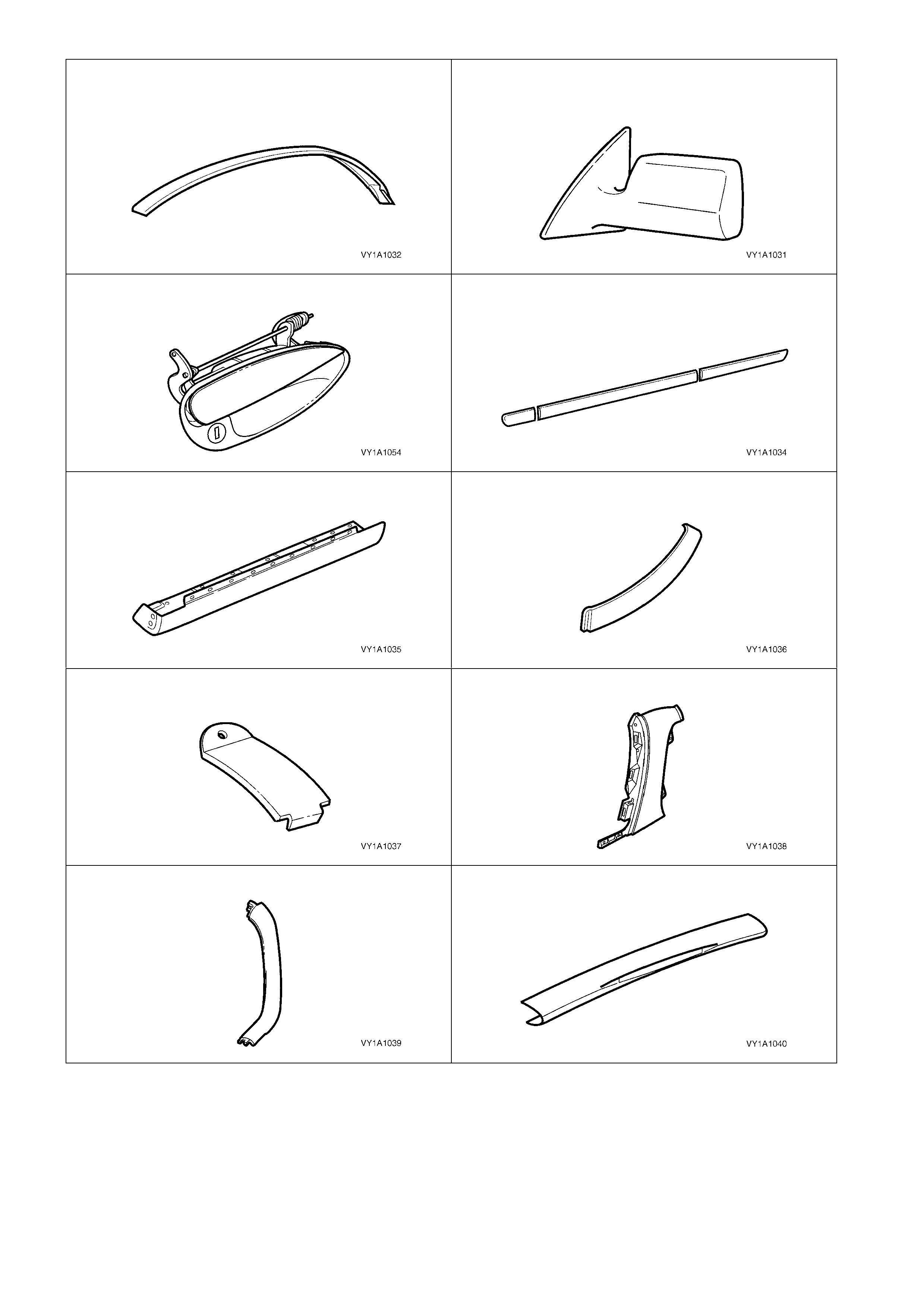
Roof Panel Joint Moulding Assembly
(Exc. Utility / Utility): PVC / PP
Outside Rear View Mirror Housing
(Painted / Unpainted): ABS / ASA - PC
Door Handle Assembly: PA 66
Body Side Moulding: ASA
Rocker Panel Moulding Assembly: PP
Quarter Panel Belt Moulding, Sedan: PPE - PA-M20
Roof Panel Joint Finish Moulding, Wagon: PP M20
Rear Quarter Window Moulding, Utility: ABS - PC-M6
Rear Window Side Moulding, Utility: ABS - PC-M6
Rear Window Upper Moulding, Utility: ABS - PC-M6
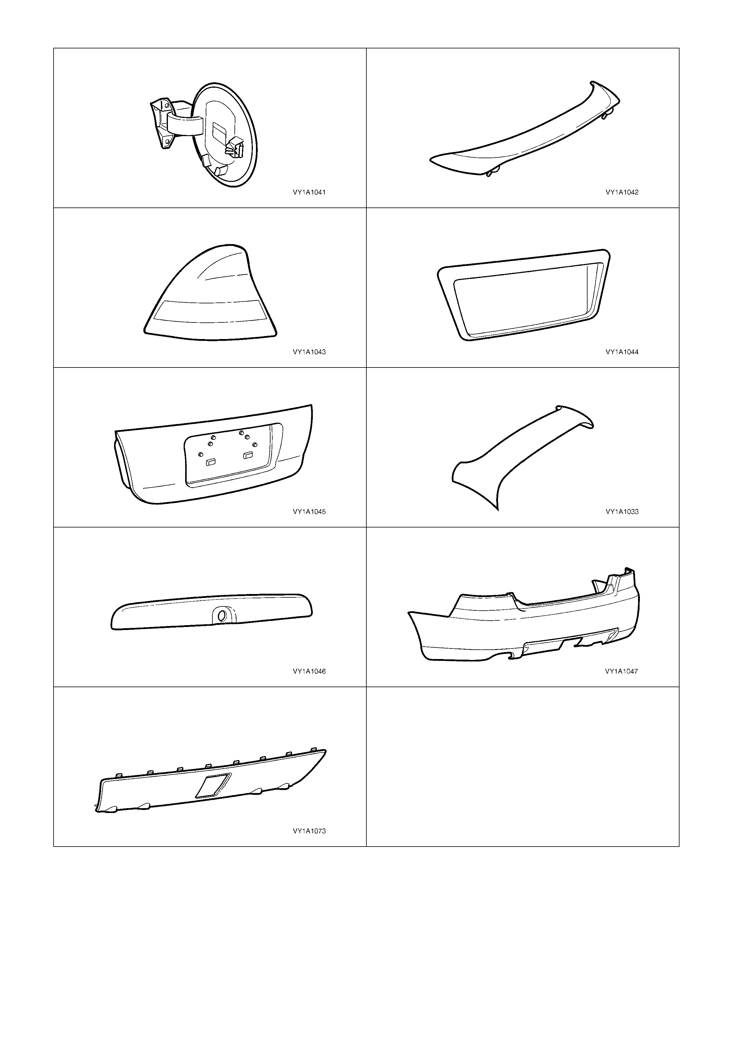
Fuel Filler Door: PPE / PA
Rear Spoiler Assembly: ABS
Tail lamp Assembly (Lens / Housing): PMMA / ABS
Rear Compartment Lid Applique, Sedan: ABS
Rear Compartment Lid Applique, Coupe: ABS
Liftgate Air Deflector Assembly, Wagon: PC - ABS
Liftgate Handle Assembly, Wagon: ABS
Rear Bumper Fascia: PP
Rear Bumper Fascia Insert, Sedan: PP
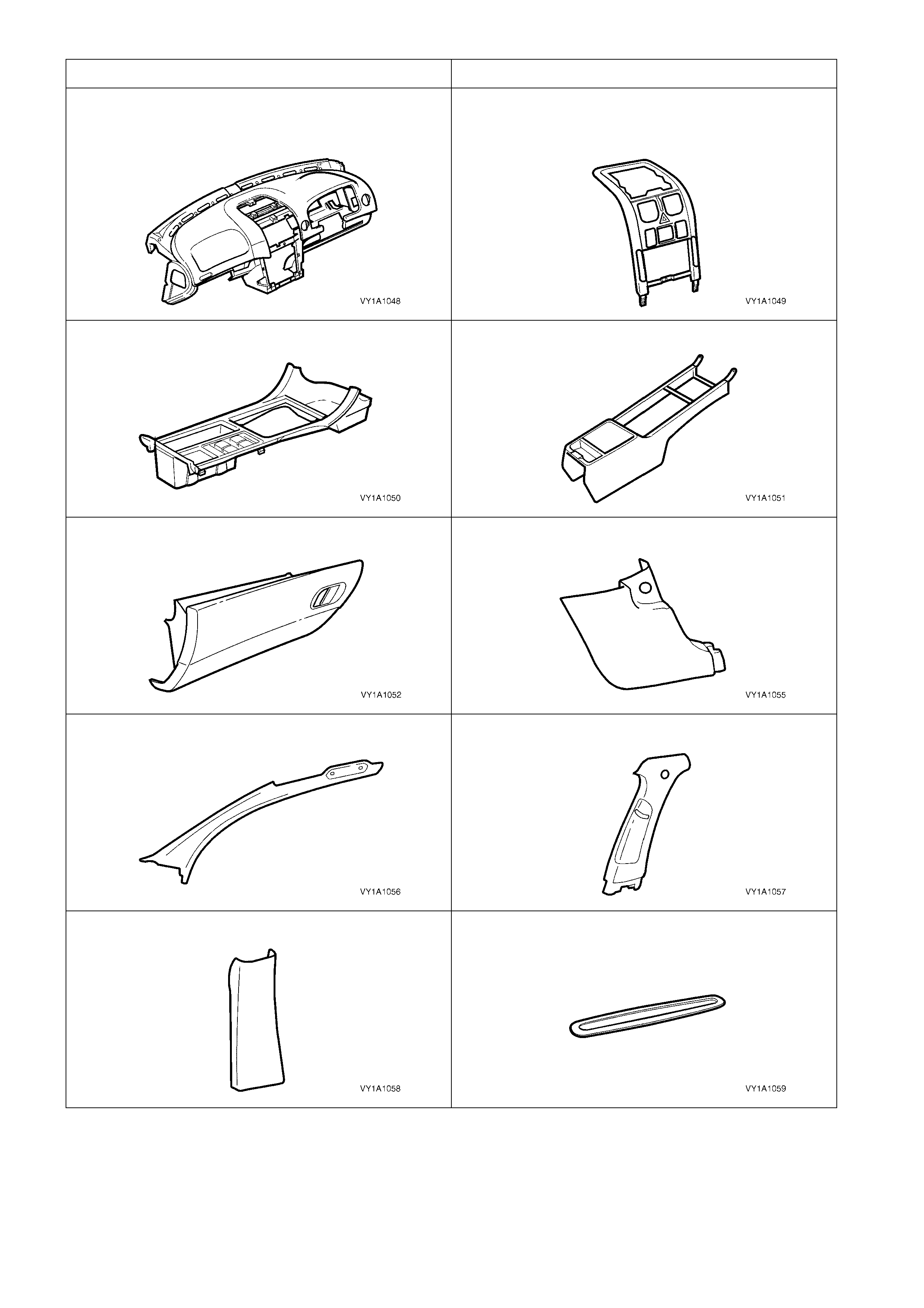
INTERIOR:
Instrument Panel Pad Assembly:
(Carrier & Pad Substrate): ABS
(Foam / Skin): PP / PVC - ABS)
Instrument Panel Centre Trim: PC – ABS
Floor Console Cover Assembly: PC - ABS
Front Floor Console: PP
Instrument Panel Compartment: PP
Hinge Pillar Trim: PP
Windscreen Side Garnish: PP
Centre Pillar Upper Trim: PP
Centre Pillar Lower Trim: PP
Side Sill Trim Plate: PP
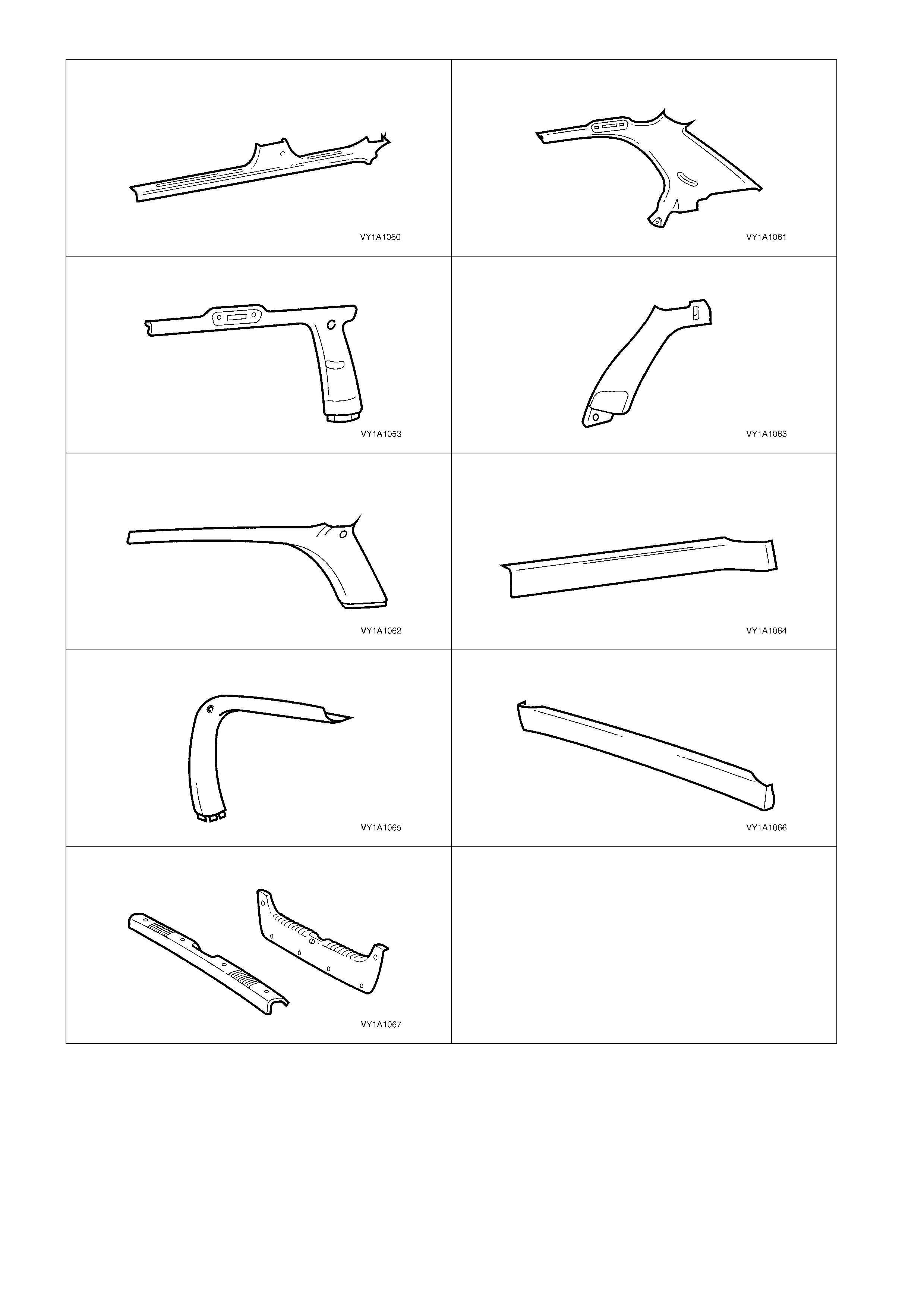
Side Sill Trim: PP
Body Lock Pillar Garnish, Sedan: PP
Body Lock Pillar Garnish, Wagon: PP
Body Lock Pillar Lower Trim, Wagon: PP
Body Rear Corner Garnish, Wagon: PP
Quarter Inner Trim Upper, Wagon: PP
Liftgate Window Upper Garnish, Wagon: PP
Liftgate Window Lower Garnish, Wagon: PP
Rear End Trim Panel: PP

9. SPECIAL STEEL PRECAUTIONS
A number of different types of steel are used for the panels and body structure of MY2003 VY Series & V2
Series II vehicles. These are as follows.
9.1 PRE-COATED STEEL
In the steel manufacturing process, a corrosion protection layer of zinc-nickel alloy, galvaneal or zinc rich
coating, is applied to one or both of the surfac es. This layer is very thin and can easily be burnt or eroded away
under repair conditions.
Most repairs such as sanding, grinding or welding will remove the protective layer. To maintain the corrosion
protection of the vehicle after repairs, both sides of the panel should be painted with a zinc rich primer, primer
surfacer and topcoat of refinish paint where possible.
NOTE: If it is not possible to cover the inside surface of the panel with paint, cavity wax should be used to
prevent premature corrosion. Refer to Section 3 BODY CONSTRUCTION in this Supplement.

9.2 RE-PHOSPHORISED STEEL
Re-phosphorised steels are used in many areas for their high strength properties, but can be repaired and welded in
the same manner as conventional low carbon steels.
9.3 HIGH STRENGTH LOW ALLOY STEEL
High strength low alloy (HSLA) steels are used in the primary structure of the vehicle because of their high
strength properties. Many are readily repairable and weldable using MIG or Arc welding equipment, however
some must not be heated or repaired at all.
Heat sensitivity and repairability of the material is dependent on the chem ical composition of the specific HSLA
grade and/or level of cold work in the manufacture of the part.
The further application of heat may anneal (soften) the material, while cold repair can fatigue and weaken it,
leading to failure.
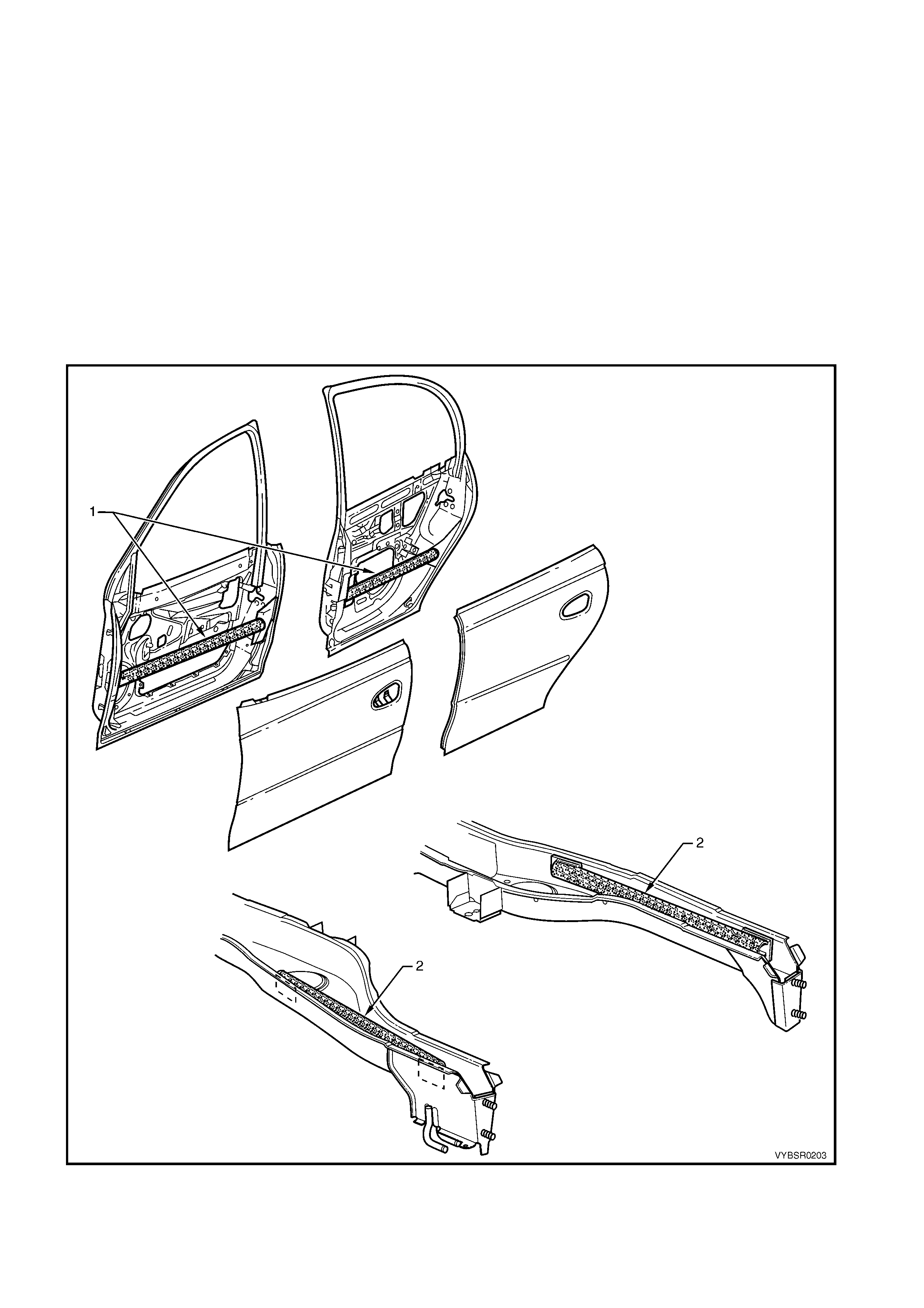
The door anti-intrusion beams (1) fitted within all doors are critical to driver/passenger safety in side impact
displacements, refer to Figure 2-8.
For Coupe vehicles only, each rear side rail assem bly is also fitted with a rear side rail reinforcem ent (2) which
performs a critical function in the combined strength of the rear end.
CAUTION: These components are manufactured from HSLA and must not be heated, welded or
straightened in any way. If a door anti-intrusion beam or rear side rail reinforcement is damaged, the
only acceptable practice is to replace the complete door or rear side rail assembly.
Figure 2-8

10. CAVITY FOAM
During manufacture of the vehicle, a cavity foam block is fitted within each pillar cavity as follows:
• Sedan – The hinge, centre and lock pillars, refer to Figure 2-9,
• Wagon – The centre pillar only, also refer to Figure 2-9 ,
• Coupe - The hinge, centre and lock pillars, refer to Figure 2-11,
• Utility – The hinge and centre pillars, refer to Figure 2-10.
This foam material, when subjected to a temperature of approximately 160°C, expands up to 10 times its original
size to seal the cavity and reduce noise transmission.
The use of this material poses no health and safety risk to a repairer, unless it is heated to temperatures
associated with using oxy / acetylene equipment or welding, as toxic fumes will be emitted which must not be
inhaled.
Prior to welding or heating in the areas shown, the foam must first be removed – usually by cutting it out with a
knife.
If a panel or section is replaced, or repair work is
performed where the foam is removed, it must be
replaced with a commercially available equivalent,
such as those listed, using the following procedure
prior to final trim assembly.
NOTE 1: The hinge pillar inner panel assembly and
quarter panel inner assembly service parts are
supplied with uncured foam blank s . These m ust not be
rem oved as they act as a support f or the aeros ol c avity
foam.
NOTE 2: Always read and follow the directions and
safety instructions with the product prior to usage.
CAVITY FOAM EQUIVALENTS
BRAND PRODUCT
Sista Multi Purpose Foam
Ramset Expandable Polyurethane Foam
Selleys Space invader
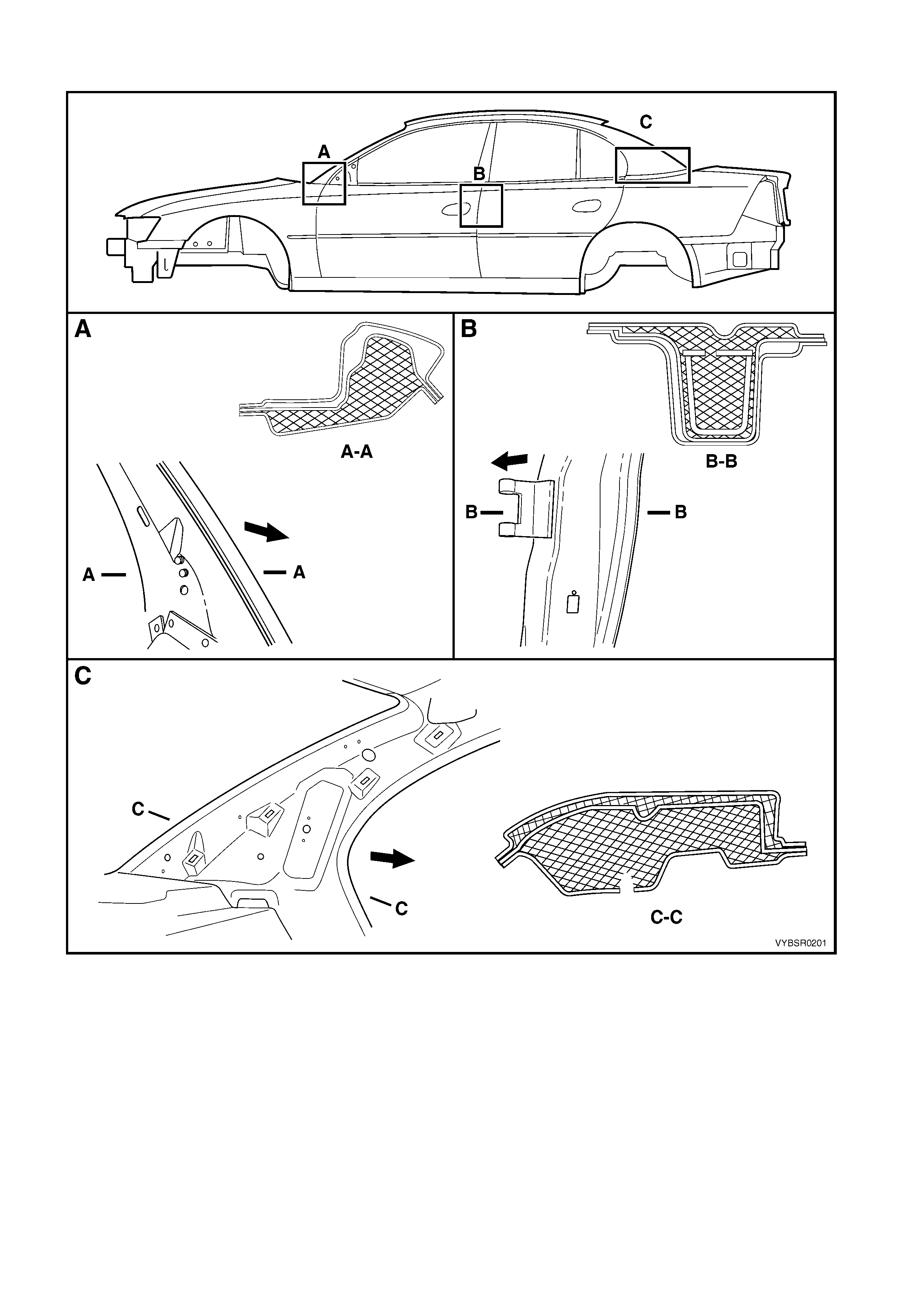
SEDAN & WAGON
Figure 2-9
Legend
A. Hinge Pilar – Sedan Only
B. Centre Pillar – Sedan & Wagon
C. Lock Pillar – Sedan Only
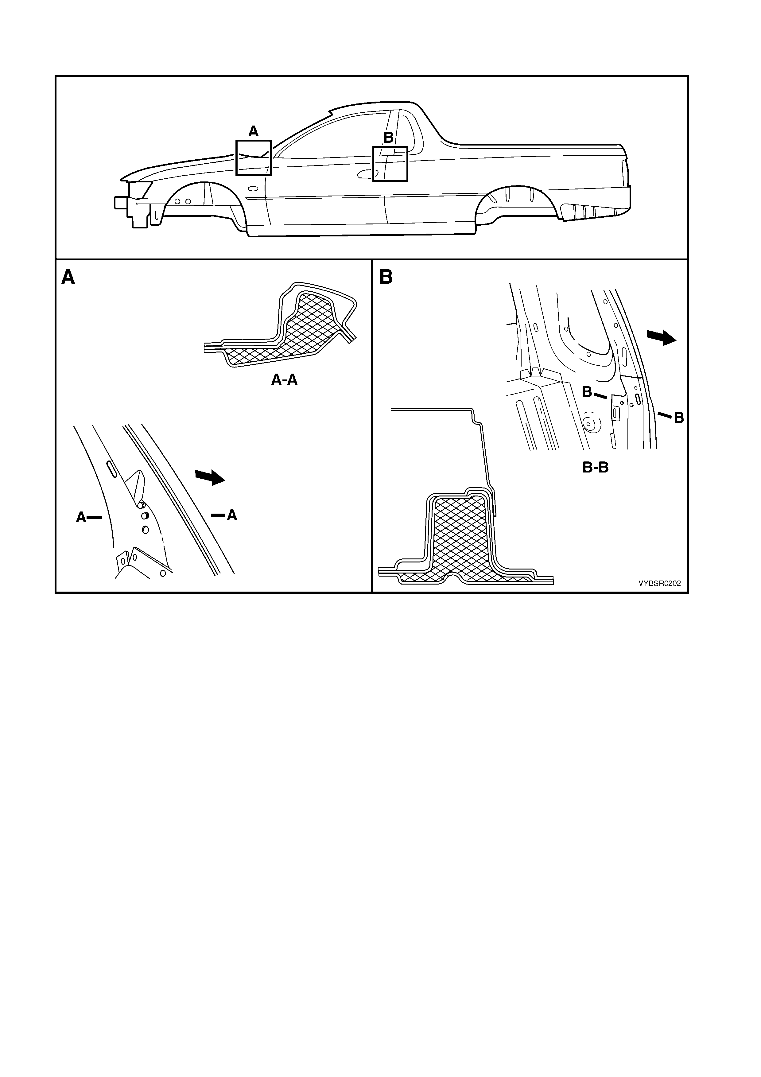
UTILITY
Figure 2-10
Legend
A. Hinge Pilar
B. Centre Pillar
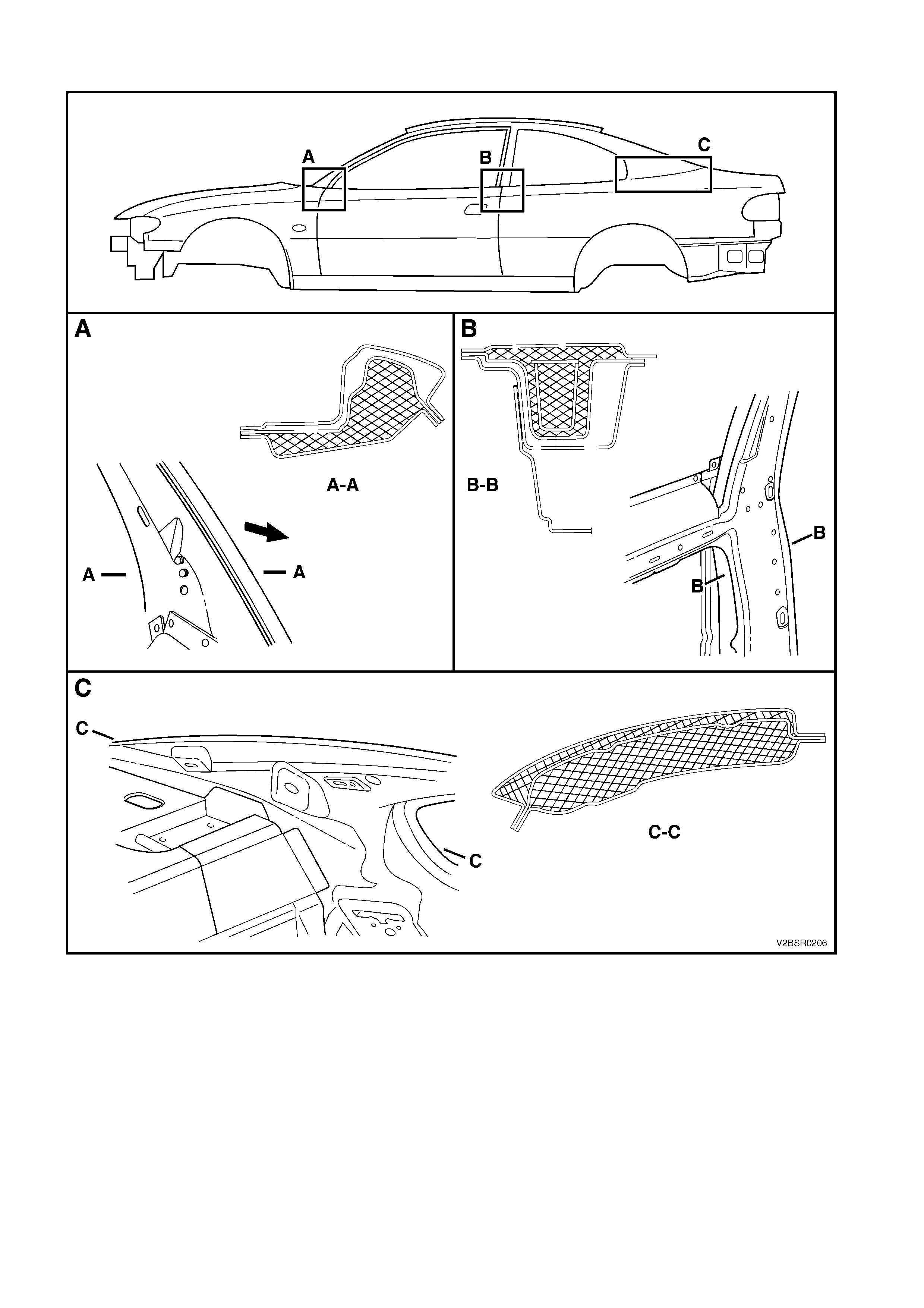
COUPE
Figure 2-11
Legend
A. Hinge Pilar
B. Centre Pillar
C. Lock Pillar
10.1 CAVITY FOAM – REPLACE
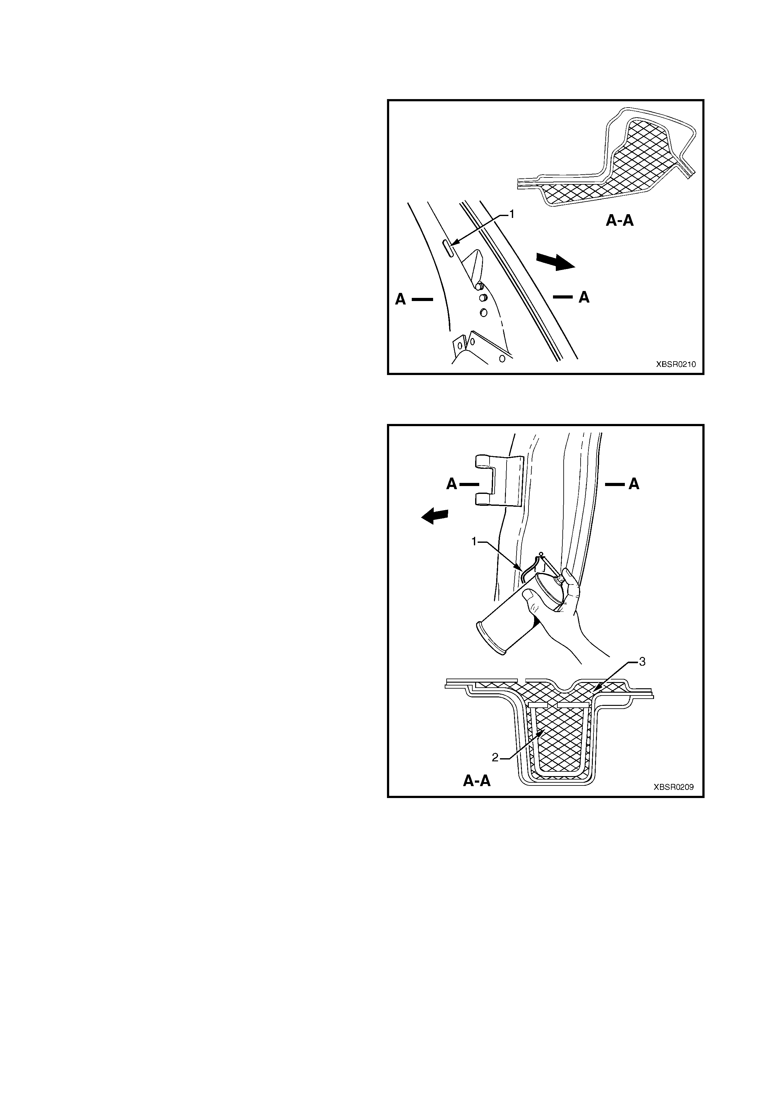
HINGE PILLAR
1. For the hinge pillars, insert the nozzle of the
aerosol into the trim clip slot (1) above the foam
blank.
2. Spray foam into the cavity for several seconds
while drawing the nozzle out. Fill the area to a
height of approximately 50 mm.
3. Once cu red, r emove a small amount of foam using
a probe to enable the trim clip to seat correctly.
Figure 2-12
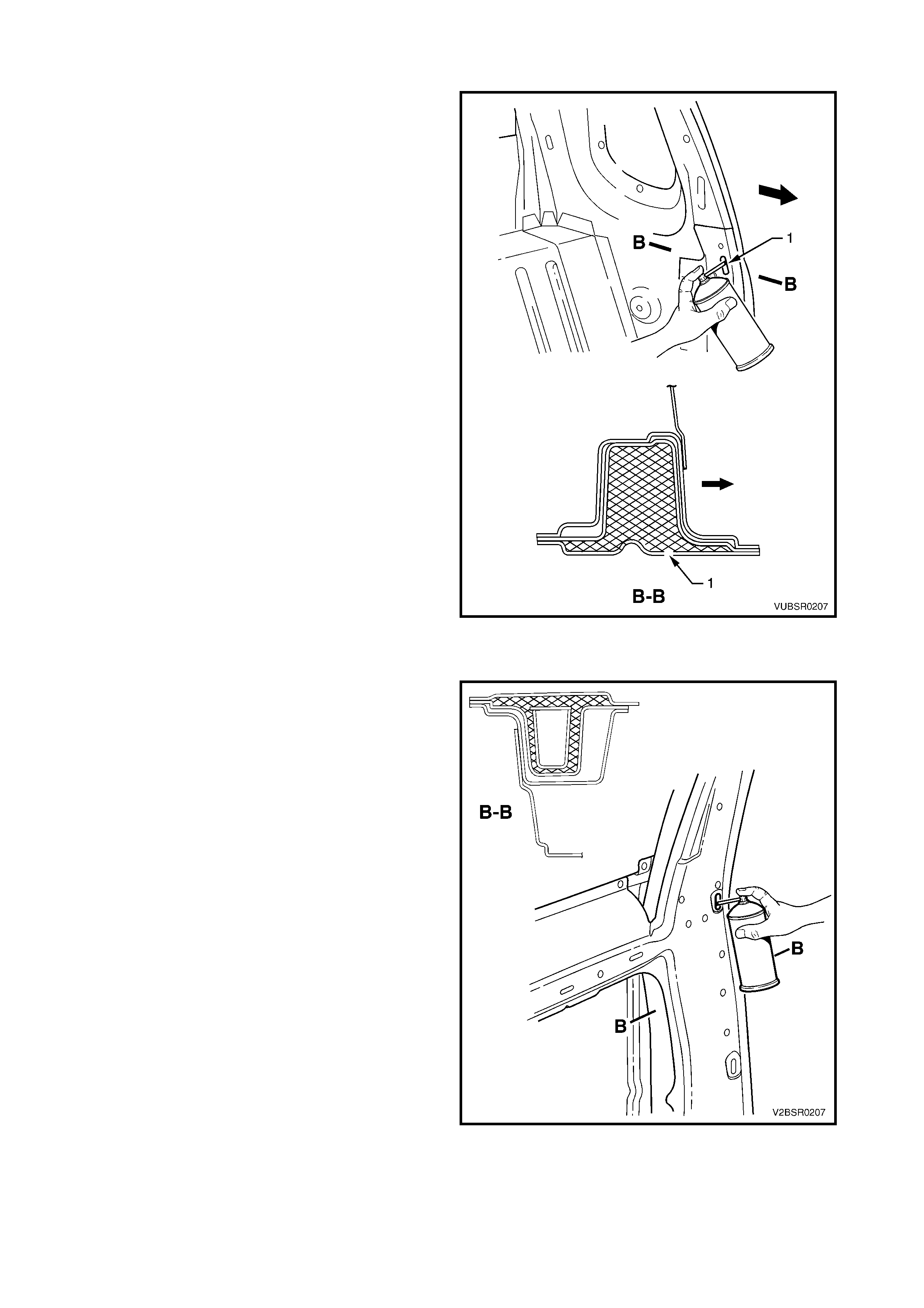
CENTRE PILLAR, SEDAN & WAGON
1. For the Sedan and Wagon centre pillars, ensure
the door light switch wire (1) is protr uding f rom the
door light switch opening in the centre pillar.
2. Insert the nozzle of the aer osol as high as poss ible
within the cavity of the centre pillar inner
reinforcement (2), through the door light switch
hole.
NOTE: The nozzle needs to reach above the foam
block to avoid the foam falling down the cavity.
3. Spray foam into the cavity for several seconds
while drawing the nozzle out. Fill the area to a
height of approximately 50 mm.
4. Insert the nozzle of the aerosol into the trim clip
slot on the inner side of the pillar, above the foam
blank. Spray foam into the cavity (3) for several
seconds while drawing the nozzle out of the cavity.
Fill the area to a height of approximately 50 mm.
5. Once cured, rem ove a sm all amount of foam f rom
the trim clip slot and door light switch hole using a
probe.
NOTE: Any residual foam can disrupt operation of the
switch; ensure there is plenty of clearance around the
switch.
Figure 2-13
CENTRE PILLAR, UTILITY
For the Utility centre pillars, insert the nozzle of the
aerosol into the trim clip slot (1) above the foam blank.
1. Spray foam into the cavity for several seconds
while drawing the nozzle out. Fill the area to a
height of approximately 50 mm.
2. Once cu red, r emove a small amount of foam using
a probe to enable the trim clip to seat correctly.
Figure 2-14
CENTRE PILLAR, COUPE
1. For the Coupe centre pillars it is not possible to f ill
all cavities . Ins ert the nozzle of the aerosol into the
trim clip slot in the quarter panel inner assembly
and spray foam into the cavity for se veral s econds
while drawing the nozzle out of the cavity. Fill the
area to a height of approximately 50 mm.
2. Once cured, remove any residual foam as required
Figure 2-15
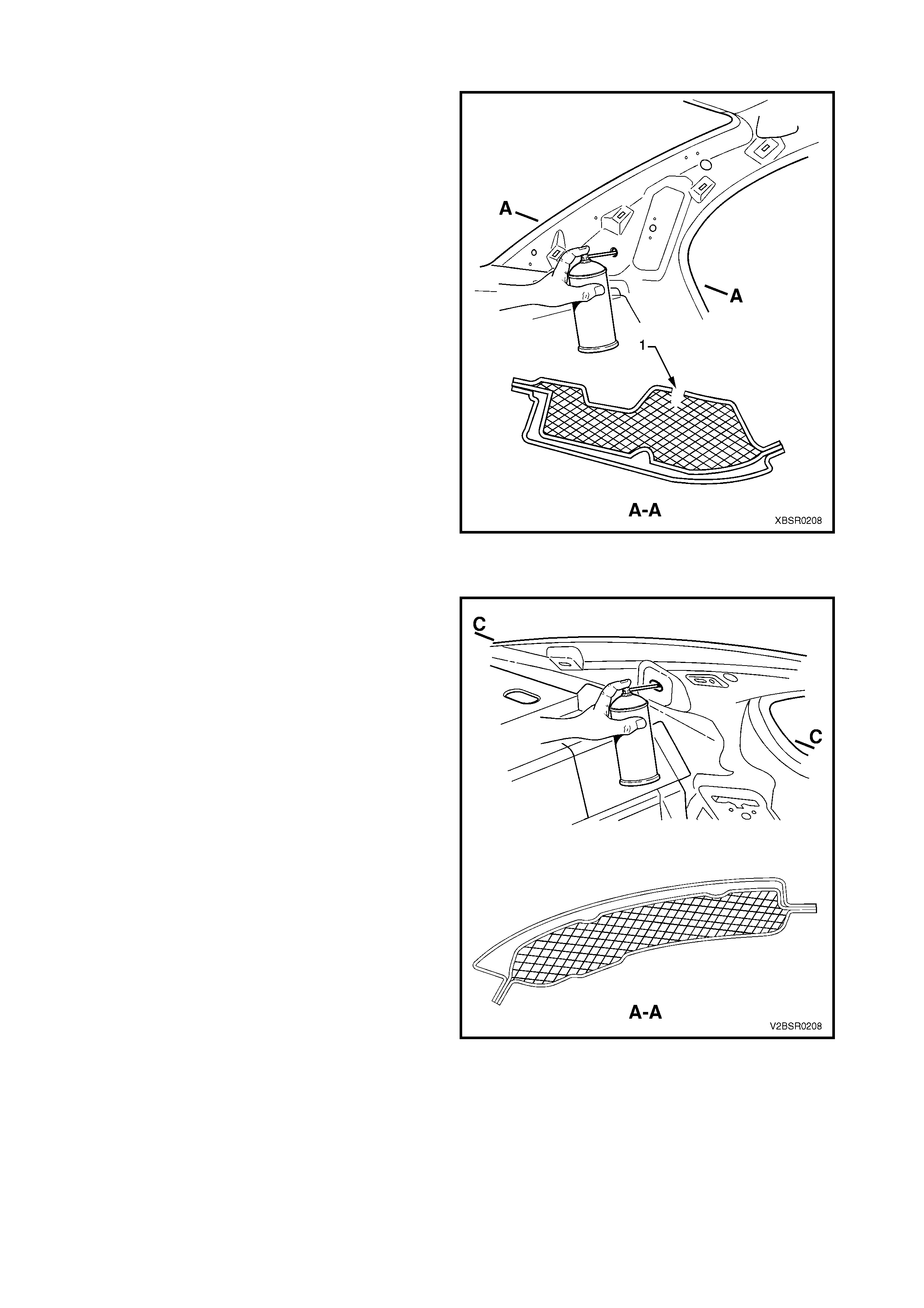
LOCK PILLAR, SEDAN
1. For the Sedan lock pillars, two cavities are filled
originally. As the outer cavity is inaccessible, it is
not a requirement to fill this cavity with aerosol
foam.
2. Insert the nozzle into the trim locating hole (1) as
shown and spray foam into the cavity between the
lock pillar reinforcement and quarter panel inner
assembly for several seconds to a height of
approximately 50 mm.
3. Once cu red, r emove a small amount of foam using
a probe to enable the trim stud to seat correctly.
Figure 2-16
LOCK PILLAR, COUPE
1. For the Coupe lock pillars, two cavities are filled
originally. As the outer cavity is inaccessible, it is
not a requirement to fill this cavity with aerosol
foam.
2. Insert the nozzle into the seatbelt mounting hole
and trim locating holes as shown and spray foam
into the cavity between the lock pillar
reinforcement and quarter panel inner assembly
for several seconds to a height of approximately
50 mm.
3. Once cu red, r emove a small amount of foam using
a probe to enable the trim stud to seat correctly.
Figure 2-17

11. LPG PRECAUTIONS
Liquefied Petroleum Gas (LPG) is available for VY Series Sedan, Wagon and Utility vehicles with V6 engine and
automatic transmission.
Automotive LPG is a hydrocarbon fuel that consists predominantly of propane (60% - 90%) and butane (40% -
10%). The propane to butane mix varies on the source and manufacturing location.
Pure LPG is c olourless , odourles s and tasteles s. However, c om m ercial LPG has a pungent odour to enable LPG to
be detected by a human. This pungent odour is achieved by adding a chemical to the LPG to enable a human to
detect the LPG at concentrations of less than 0.5% by volume in air.
LPG boils at approximately -40°C at atmospheric pressure. This means that the LPG must be pressurised to
approximately 750 kPa to maintain it in a liquid state.
11.1 GENERAL SAFETY PRECAUTIONS
• LPG in the vapour f orm is highly inflamm able. Do not sm ok e or allow naked f lam es, or any ignition source near
the vehicle.
• Never allow LPG to come in c ontact with any part of the body. Due to the very low boiling point of LPG, it readily
absorbs heat from its surroundings, or any surface it comes into contact with when released into the
atmosphere. LPG can cause severe frostbite if it is allowed to come into contact with the human body.
• When working on the LPG system, always wear suitable clothing, including gloves and safety goggles, to
prevent personal injury.
• For more detailed information, refer to Section 8A2, LPG SYSTEM in the MY2003 VY Series & V2 Series II
Service Information.
11.2 REPAIR WORK TO VEHICLE FITTED WITH LPG
DRAINING THE SERVICE LINES
CAUTION: T he v ehicle cannot be operated on LPG in the w orkshop, unless the w orkshop is a Specialist
Gas Workshop (in accordance with the current Australian Standards AS 2746-1985) and LPG is
specifically required for testing. Therefore, only at the completion of the following procedure, with the
manual service valve closed, all the LPG in the service lines exhausted and the vehicle running on
petrol, can the vehicle be driven into the workshop.
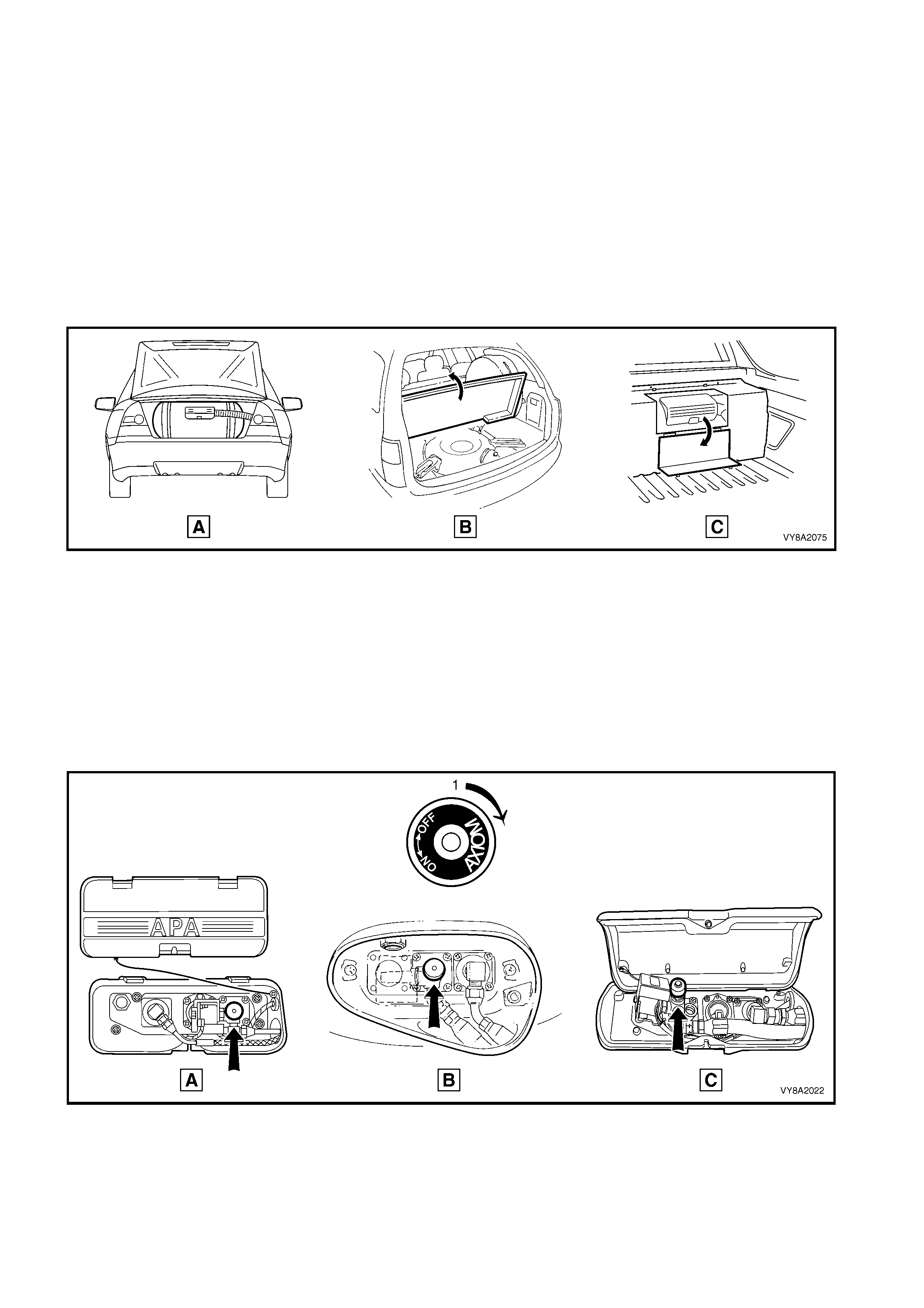
1. Park the vehicle in a well ventilated area, away from any ignition source when performing this operation.
2. For Sedan, open the rear compartment lid (A).
For Wagon, open the liftgate and raise the rear compartment floor carpet (B).
For Utility, open the access cover on the LPG tank cover (C).
Refer to Figure 2-18.
Figure 2-18
3. Remove or open the LPG tank valve box cover.
4. Turn the manual s er vice valve of f in the dir ect ion shown (1) , re f er to F igure 2- 19, (A) Sedan, (B) Wagon, (C )
Utility.
CAUTION: If at any time the manual serv ice valve becomes stuck, no service operations on the system
will be possible. Should for any reason the valve stick, the tank will have to be returned to the tank
manufacturer (APA) to arrange a replacement tank.
Contact: APA Industries, 190 Colchester Road, Kilsyth, Victoria 3137.
Phone - (03) 9720 2855, Fax - (03) 9761 4495
E-mail - [email protected].au
Figure 2-19
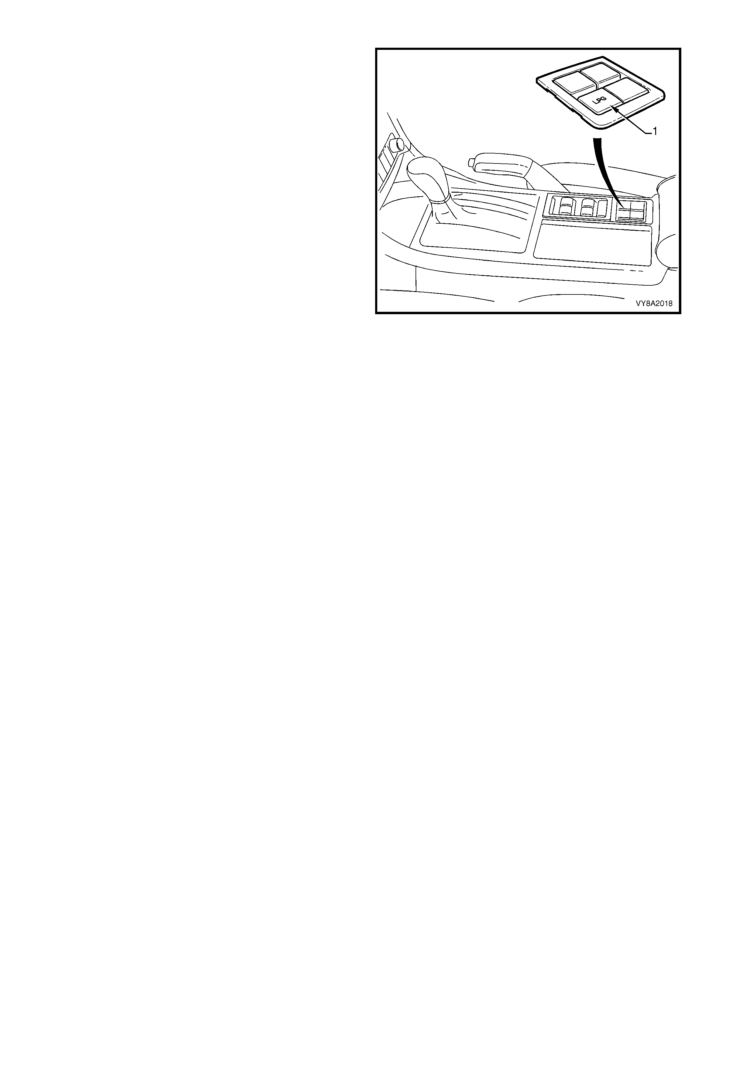
5. If required, press the fuel m ode switch (1) to place
the vehicle in LPG m ode. With the ignition on, the
LPG icon should be displayed on the instrument
cluster multi-function display.
6. Start the engine and allow to run on LPG until the
engine stalls, then crank the engine several times
to ensure the service lines are empty of LPG.
7. Press the fuel mode switch again to place the
vehicle in petrol mode. With the ignition on, the
LPG icon should not be displayed on the
instrument cluster multi-function display.
8. Disconnect the battery earth lead before
performing any service operations.
NOTE: If it is not possible to start and run the engine
out of LPG, the service lines should be cracked open
to allow them to be em ptied of LPG in accordance with
the current Australian Standards AS 2746 - 1985.
Figure 2-20
LPG TANK REMOVAL
W here other than the m ost minor repair work is being perform ed on the vehicle, the LPG tank should be removed
from the vehicle, leak tested and stored in a safe place.
NOTE: Any servicing or testing of the High Pressure area of the LPG sys tem m ust be perform ed by trained and/or
licensed LPG installers or f itters in a Specialist Gas W ork shop in accordance with Australian Standards AS 2746 -
1985 and AS 1425 - 1989.
The High Pressure area of the LPG system consists of the filler line, LPG tank, service line, LPG lock-off and
converter. Qualified personnel as described above must carry out removal and replacement of components in this
area of the system.
If difficulty is experienced in contacting licensed personnel, please contact:
Impco Technologies
1 - 3 Taunton Drive, Cheltenham, Vic 3192.
All Correspondence To:
PO Box 233, Cheltenham, Vic 3192
Tel: (03) 9584 5644, Fax: (03) 9583 0696