
SECTION 3 - BODY CONSTRUCTION
IMPORTANT
Before perfo rming any Service O perat ion or o th er pro cedu re describ ed in th is Section, refer to Section
00 CAUTIONS AND NOTES and Section 2 PRECAUTIONS in this Supplement for correct workshop
practices with regard to safety and/or property damage.
CAUTION
The Structure of the M Y 2003 VY & V2 Series II body shell has been developed using complex design
and development techniques. In addition to meeting all required standards, the v ehicle body is also a
critical part of the overall safety systems. It is therefore imperative the repair procedures described
here are adhered to during all vehicle body repairs.
1. GENERAL DESCRIPTION
1.1 BODY STRUCTURE PART REFINISHING
1.2 ANTI-CORROSIVE TREATMENT
1.3 PAINT REFINISHING
PANEL REFINISHING
PAINT CODE
2. BUMPER IMPACT BAR ASSEMBLIES
2.1 FRONT
REMOVE
REINSTALL
2.2 REAR
REMOVE
REINSTALL
3. SPECIAL TOOLS

1. GENERAL DESCRI PTI O N
Section 3, Body Construction, has been divided into five sub-sections. This sub-section contains the general
information relative to all body styles. Sub-section 3A contains information specific to Sedan vehicles, sub-section
3B is specific to Wagon, 3C for Utility and 3D for Coupe.
Each sub-s ection descr ibes the body s tructure as a whole and provides a detailed breakdown of the body structure
components, key body dimensional measurements and body margin tolerances.
The various sealers and adhesives used throughout the body are also described, as it is imperative that only the
correct materials are used for repairs.
The correct cavity wax, deadeners and paint refinishing techniques are also imperative if the vehicle is to be
returned to its original condition.
When replacing or repairing a part or sub-assembly, care must be taken to ensure that correct alignment and
strength of unit as a whole is maintained. In some instances, major damage to the body or frame can be repaired
more effectively and economically by replacing a part or sub-assembly with a new one, rather than repairing the
damaged part.

1.1 BODY STRUCTURE P ART REFINISHING
The vehicle body structure is designed to meet or exceed many regulations, including crash performance and
occupant protection, etc. When replacing or repairing a part or sub-assembly, care must be taken to ensure that
correct alignment and strength of unit as a whole is maintained.
In some instances, major damage to the body structure can be repaired more effectively and economically by
replacing a part or sub-assembly with a new one, rather than repairing the damaged part.
Spot welding is used extensively for joining panels or assemblies, however special adhesives are playing an ever
increasing role in the joining of body structure components, either on their own or together with spot welds. W here
repairs are performed, it is imperative that effective rust proofing techniques, as outlined in the following
paragraphs, be observed.
It is for these reasons that qualified persons with suitable training and qualifications only perform the repair or
replacement of body structure components.

1.2 ANTI-CORROSIVE TREATMENT
Precoated and galvanised steel is used extensively for various body structure components for increased corrosion
protection. Body panels such as the engine hood, door and deck lid outer panels ar e precoated on the inner surf ace
of the metal to improve corrosion protection. Other body structure members have complete double-sided galvanised
protection.
In addition, a rust preventative material (cavity wax) is sprayed after paint application to areas such as the interior
surfaces of doors, etc. Refer to 6. CAVITY WAX in Section, 3A – Sedan, 3B – Wagon, 3C – Utility or 3D – Coupe.
Any repair or replacement of panels, assemblies, etc. that disturb this anti-corrosive treatment must be resealed
and should be included as part of the repair or replacement operation.
Anti-corrosive compounds used for repairs should be light bodied materials designed to penetrate between metal-
to-metal surfaces such as pinch weld flanges and integral panel attaching points.
All bare metal sur f ac es must be tr eated with metal conditioner and pr imed. T hes e operations need to be c arr ied out
prior to the application of sealer s, waxes and s ound deadeners. Attac hing points of new replacem ent panels s hould
be resealed. T he hemm ing flanges of replacem ent doors, lif tgates, endgates and r ear compartm ent lids will require
resealing.
Open joins that require bridging of the sealer to close a gap should be sealed with a heavy-bodied caulking material.
When colour application is required to restore repaired areas to original appearance, conventional refinishing
preparation, undercoat build-up and colour application techniques should be employed.
When deadeners are disturbed during damage repair, or a panel has been replaced, the deadener material must be
replaced with an equivalent material. The location and pattern for replacement material can be determined by
observing the original deadener application outlines. Refer to 5. BODY SEALING, ADHESIVES & DEADENERS, in
Section, 3A – Sedan, 3B – Wagon, 3C – Utility or 3D – Coupe.
1.3 PAINT REFINISHING
PANEL REFINISHING
Metal service replacement parts (or assemblies) are painted with a black, high bake factory primer. To ensure
sound adhesion of colour coats in service, the following refinish steps are necessary.
1. Clean part with a wax and grease removing solvent such as Prepsol.
2. Scuff-sand panel lightly with wet and dry number 400 paper and water. Avoid cut throughs. Reclean part, and
then apply sealer to entire part.
3. If the factory prim er coat has been cut through, apply metal conditioner to the exposed bare metal. Follow the
directions on container label.
4. Apply primer-surfacer to the entire part; allow to dry thoroughly before sanding.
5. Sand primer-surfacer using wet and dry number 400 paper and water. Do not sand sealer.
6. Re-clean part.
7. Apply colour coats to parts as directed on the container label.
8. Follow directions on container label for drying time before compounding.
9. Compound part by hand or with power equipment.
10. Non-sealing polish may be applied after rub- out if des ired. Waxes however, should not be applied until the paint
finish has aged for at least two months.
NOTE: Always follow the paint manufacturer’s recommendations to ensure a high quality durable finish is achieved.
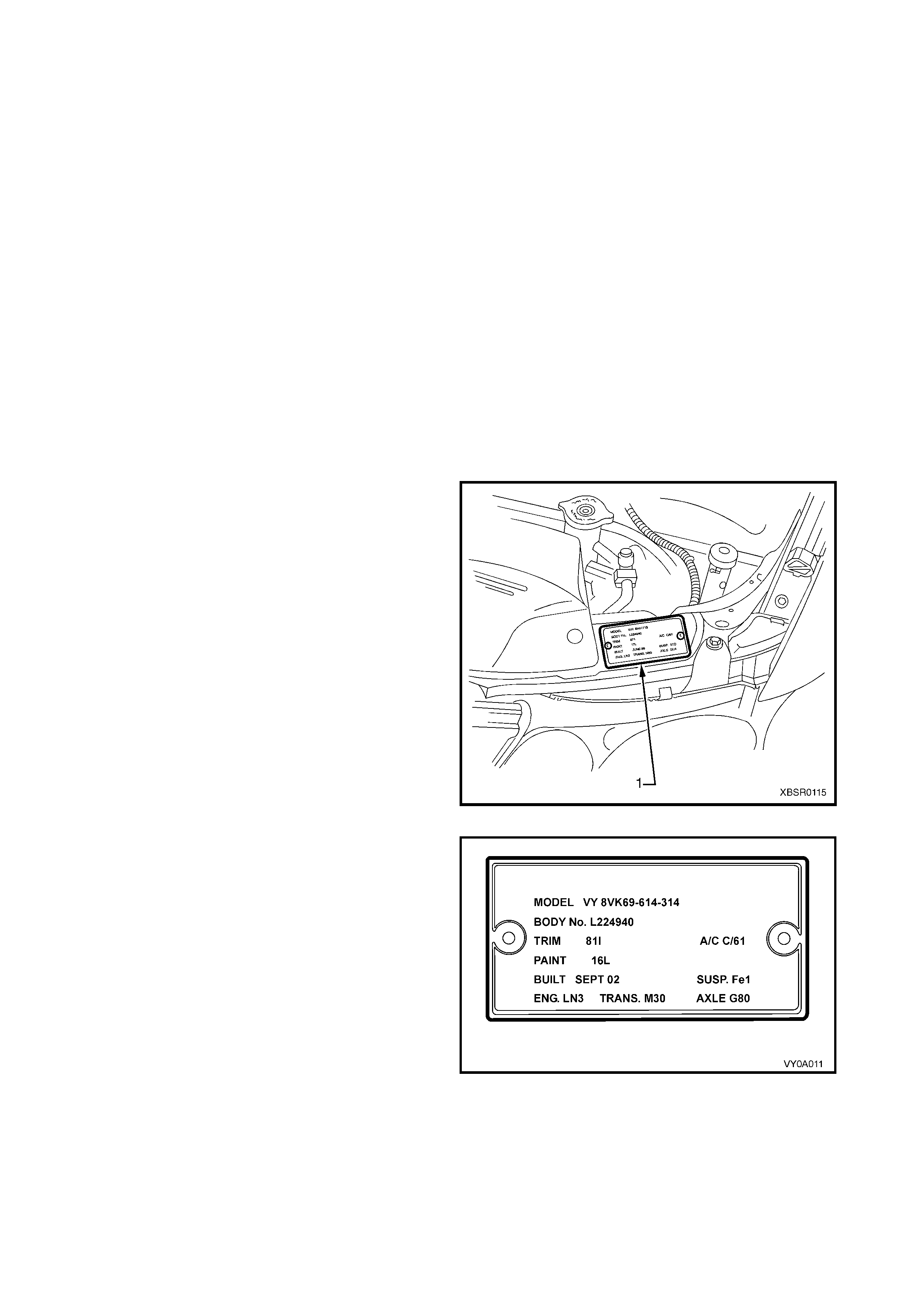
PAINT CODE
The Paint Code for the vehicle can be found on the
Body and Option Identification Plate (1).
Figure 3-1
The Paint Code enables a ref inish paint to be m atc hed
with the original paint colour.
NOTE: The paint on the vehic le m ay not exactly m atch
the original colour due to fade, in which case paint
colour m atching will be required. As this is an acquir ed
skill, it is a task that must be performed by qualified
individuals.
Figure 3-2
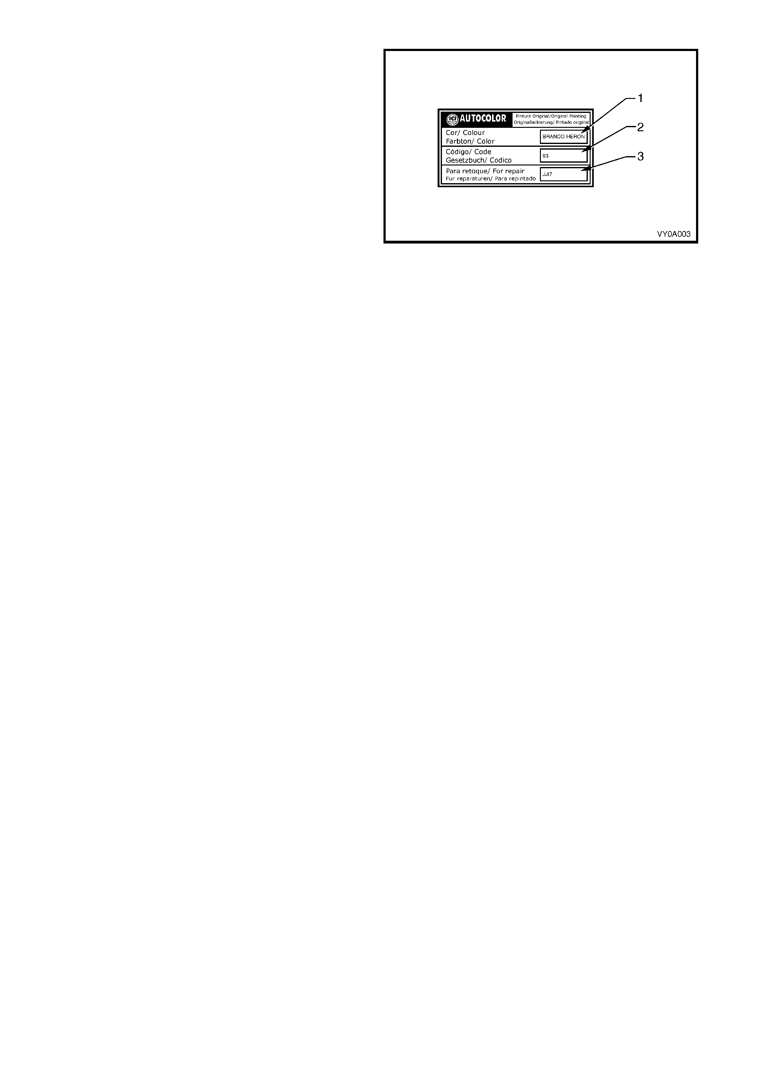
Export vehicles for Brazil also have a paint label that is
located on the left-hand B-pillar and contains the paint
colour (1), paint code (2) and repair paint (3) for the
vehicle.
Figure 3-3
2. BUMPER IMPACT BAR ASSEM BLIES
2.1 FRONT
The front bumper impact bar assembly not only acts as a m ount and support for the bum per fascia, but is also
critical in the dispersion of crash energy. Hence, it plays an integral role in the operation of the vehicle’s safety
systems.
Repair of the bar assembly should be limited to replacement, as straightening and/or heating can weaken the
bar assembly, resulting in incorrect airbag and seatbelt pretensioner operation.
REMOVE
1. Remove the f ront bumper f as c ia assembly, r ef er to
2.2 FRONT BUMPER FASCIA ASSEM BLY in the
MY 2003 VY & V2 Series II Service Information.
2. If fitted, remove the radiator air lower baffle, refer
to Section 6B1 or Section 6B3 in the MY 2003 VY
& V2 Series II Service Information.
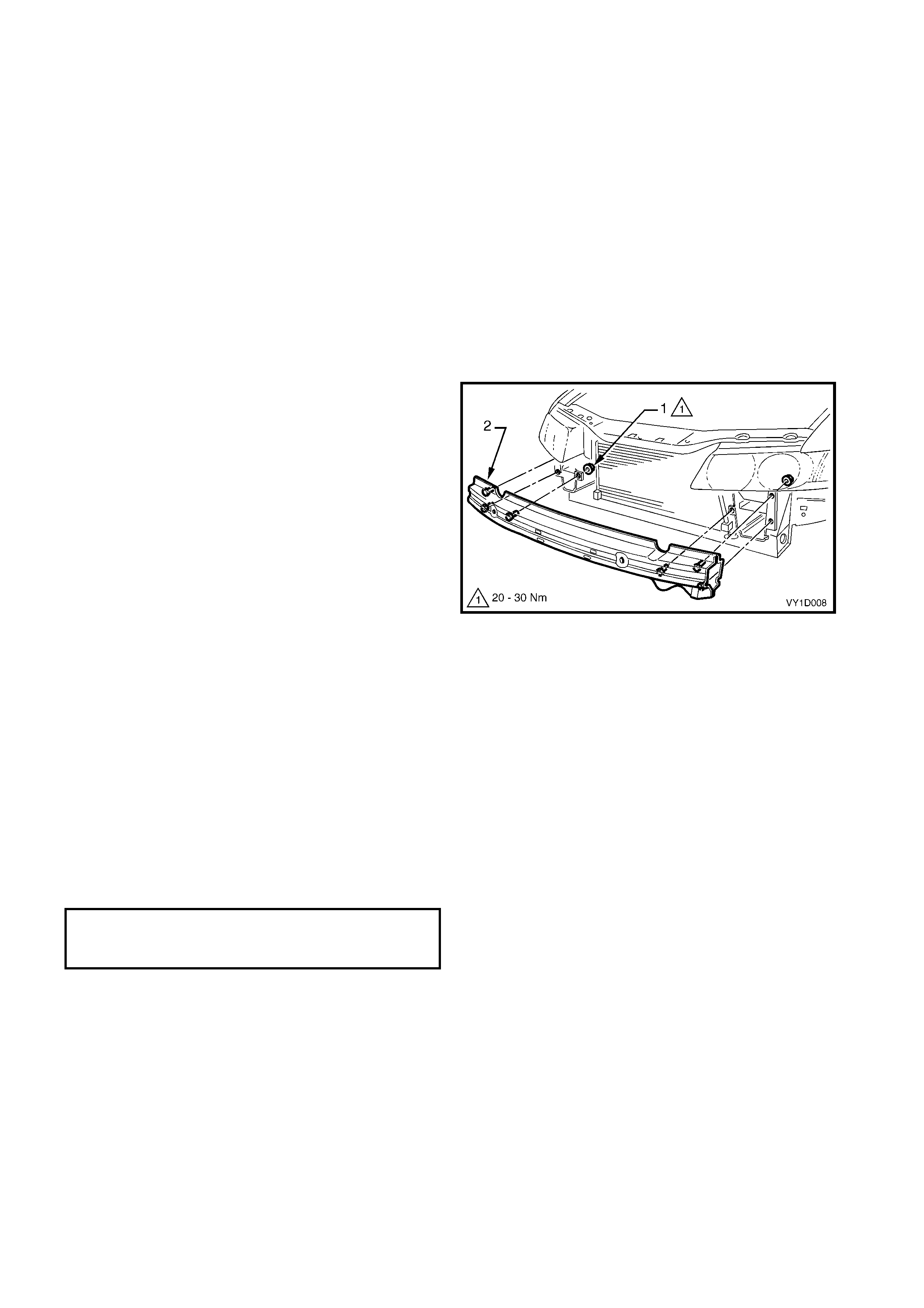
3. Remove the nuts (1), three places each side,
attaching the bar assembly (2) to the vehicle.
4. Remove the bar assembly.
Figure 3-4
REINSTALL
NOTE: Check the vehicle’s front body dimensions
as required to ensure correct alignment, refer to
Section 1A2 BODY DIMENSIONS.
1. Fit the bar assembly in position and attach each
nut. Do not tighten.
2. Ensure the bar assembly is correctly positioned
centrally and tighten the nuts to the specified
torque.
3. Refit the front bumper fascia assembly, refer to
2.2 FRONT BUMPER FASCIA ASSEM BLY in the
MY 2003 VY & V2 Series II Service Information.
FRONT BUMPER IMPACT BAR
ASSEMBLY ATTACHING NUT
TORQUE SPECIFICATION 20.0 – 30.0 Nm
2.2 REAR
REMOVE
1. Remove the rear bumper f ascia ass embly, refer to
2.5 REAR BUMPER FASCIA ASSEMBLY,
SEDAN & COUPE or 2.6 REAR BUMPER
FASCIA ASSEMBL Y , W AGON in the MY 2003 VY
& V2 Series II Service Information.
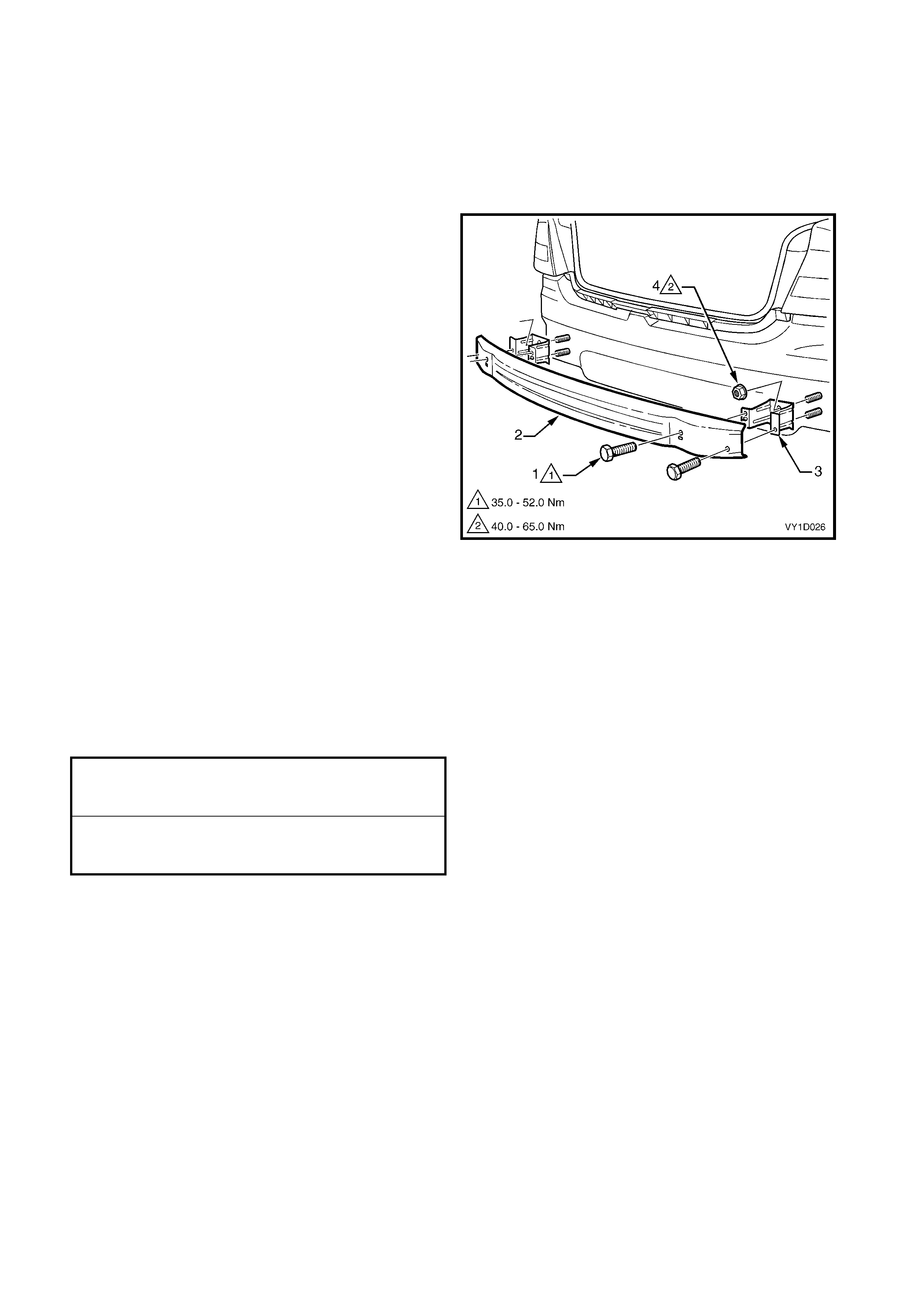
2. Remove the screws (1), two places each side,
attaching the rear bumper impact bar (2) to the
rear bumper impact bar bracket assembly (3).
3. Remove the bar.
4. If required, remove the two nuts (4), attaching the
bracket assembly to the vehicle and remove the
bracket.
Figure 3-5
REINSTALL
1. Fit the bracket assemblies in position and attach
the nuts. Tighten to the specified torque.
2. Fit the bar to the bracket assemblies and fit each
screw. Do not tighten.
3. When all screws are installed, check the bar is
centralised. Tighten the bolts to the specified
torque.
4. Refit the rear bumper fascia, refer to
2.5 REAR BUMPER FASCIA ASSEMBLY,
SEDAN & COUPE or 2.6 REAR BUMPER
FASCIA ASSEMBL Y , W AGON in the MY 2003 VY
& V2 Series II Service Information.
REAR BUMPER IMPACT BAR BRACKET
ASSEMBLY ATTACHING NUT
TORQUE SPECIFICATION 49.0 – 65.0 Nm
REAR BUMPER IMPACT
BAR ATTACHING SCREW
TORQUE SPECIFICATION 35.0 – 52.0 Nm
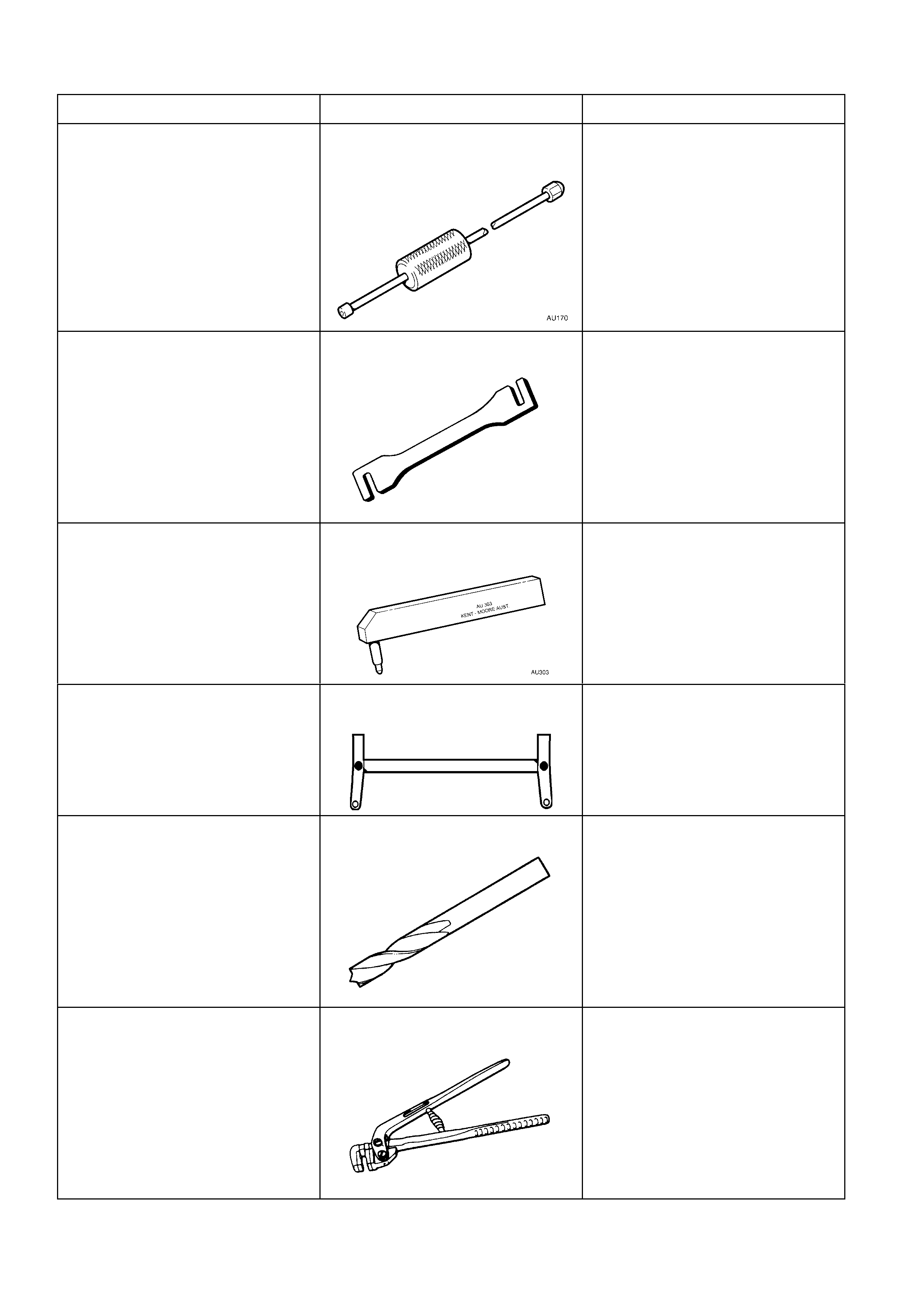
3. SPECIAL TOOLS
TOOL NO REF IN TEXT TOOL DESCRIPTION COMMENTS
AU170 DOOR HINGE SLEEVE
REMOVER
Used for removing door hinge pivot
sleeves
AU184 DOOR HINGE SETTING TOOL
Used to adjust door alignment.
AU303 DOOR HINGE SLEEVE
INSTALLER
Used to install door hinge pivot
sleeves
AU458 REAR CROSSMEMBER
CENTERING TOOL
Used when any service operation
requires removal / reinstallation of
rear suspension frame assembly,
or when checking rear end
alignment.
N/A SPOT CUTTING TOOL
Commercially available
Used for separating spot welds
N/A FLANGING TOOL
Commercially available
Used for making a joggle to form a
lap joint on overlapping panels.
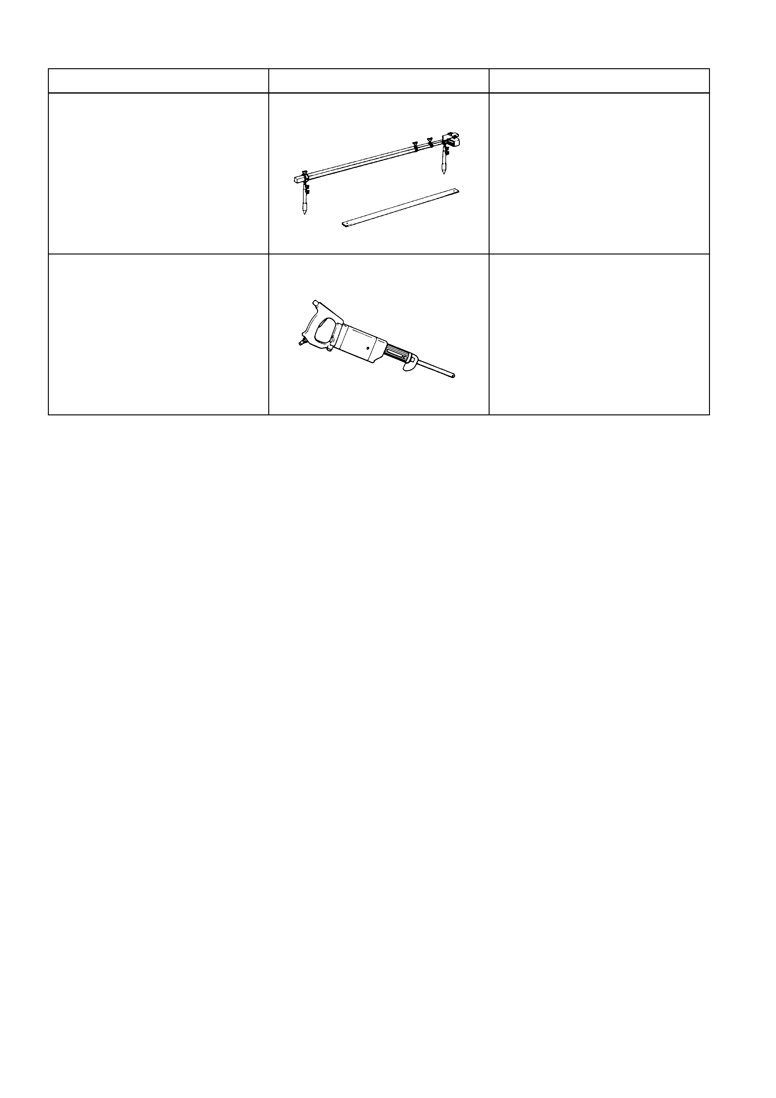
TOOL NO REF IN TEXT TOOL DESCRIPTION COMMENTS
N/A TRACKING GAUGE
Commercially available
Used for measuring body
dimensions.
N/A POWER SAW
Commercially available
Used for cutting panels. An angle
grinder may also be used when
deemed more appropriate for the
task.