
SECTION 4 – FRONT END
IMPORTANT
Before perfo rming any Service O perat ion or o th er pro cedu re describ ed in th is Section, refer to Section
00 CAUTIONS AND NOTES and Section 2 PRECAUTIONS in this Supplement for correct workshop
practices with regard to safety and/or property damage.
CAUTION
The Structure of the M Y 2003 VY & V2 Series II body shell has been developed using complex design
and development techniques. In addition to meeting all required standards, the v ehicle body is also a
critical part of the overall safety systems. It is therefore imperative the repair procedures described
here are adhered to during all vehicle body repairs.
1. GENERAL DESCRIPTION
1.1 FRONT END COMPONENTS
2. SERVICE OPERATIONS
2.1 FRONT END PANEL ASSEMBLY – REPLACE
REMOVE
REPLACE
2.2 HEADLAMP PANEL – REPLACE
REMOVE
REPLACE
2.3 FRONT WHEELHOUSE BRACKET
ASSEMBLY, FRONT WHEELHOUSE
BRACKET & FRONT BUMPER IMPACT BAR
BRACKET ASSEMBLY – REPLACE
REMOVE
REPLACE
2.4 RADIATOR LOWER SUPPORT ASSEMBLY –
REPLACE
REMOVE
REPLACE
2.5 FRONT WHEELHOUSE PANEL UPPER
SIDE RAIL – REPLACE
REMOVE
REPLACE
2.6 FRONT WHEELHOUSE PANEL ASSEMBLY –
REPLACE
REMOVE
REPLACE
2.7 FRONT WHEELHOUSE PANEL & FRONT
SIDE RAIL – PARTIAL REPLACE*
REMOVE
REPLACE
* Includes Hydraulic Modulator Bracket
2.8 FRONT SIDE RAIL ASSEMBLY – REPLACE
REMOVE
REPLACE
1. GENERAL DESCRI PTI O N
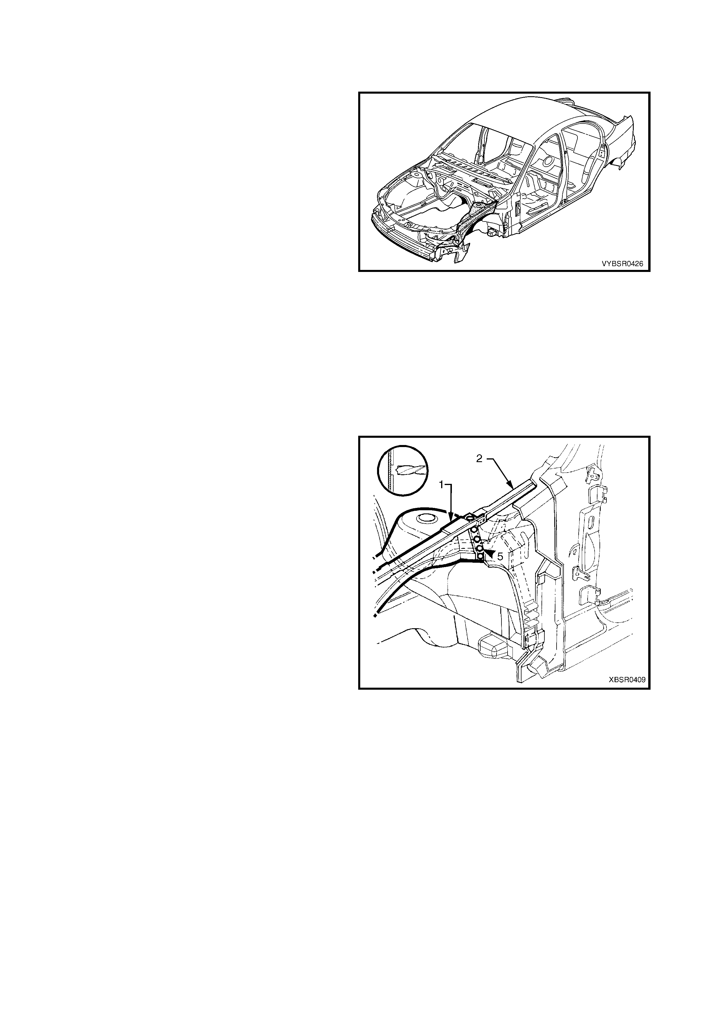
This Sect ion desc r ibes the replacement pr ocedur es f or the front-end c omponents of the MY 2003 VY & V2 Series II
body s tructur e. Rem oval of bolt- on panels and m echanic al com ponents is not c overed. Referenc e mus t be made to
the appropriate Section of the MY 2003 VY & V2 Series II Service Information.
When repairing the front end of the vehicle, care must be taken to ensure the structure is returned to its original
production configuration for the occupant protection system to operate correctly. This is especially important with
repairs to the front side rails.
Incorrect repair of the front side rails could cause the seatbelt pretensioners and airbag(s) to operate incorrectly,
affecting the timing of deployment during a collision.
The following strategy must be used when repairing the front side rails of a MY 2003 VY & V2 Series II vehicle:
1. If minor damage has occurred to the front section of the front side rail, which does not involve significant
creasing or crumple of the rail, it may be straightened.
2. If significant creasing or crumple of the rail has occurred, but is restricted to the area forward of the front
suspension crossmember, the front side rail may be cut at a point between the two crossmember mounting
bolts and a partial section welded in place as described in this Section.
3. If significant creasing or crumple of the rail has occurred and continues rearward of the front suspension
crossmember, the full front side rail assembly must be replaced.
NOTE: It is imperative that the correct body adhesives, sealers, deadeners and cavity waxes are used when
repairing the body structure of MY 2003 VY & V2 Series II vehicle. Refer to 5. BODY SEALING, ADHESIVES &
DEADENERS and 6. CAVITY W AX in Section 3A (Sedan), 3B (Wagon), 3C (Utility) or 3D (Coupe) for details of
the correct materials and their commercially available equivalents.
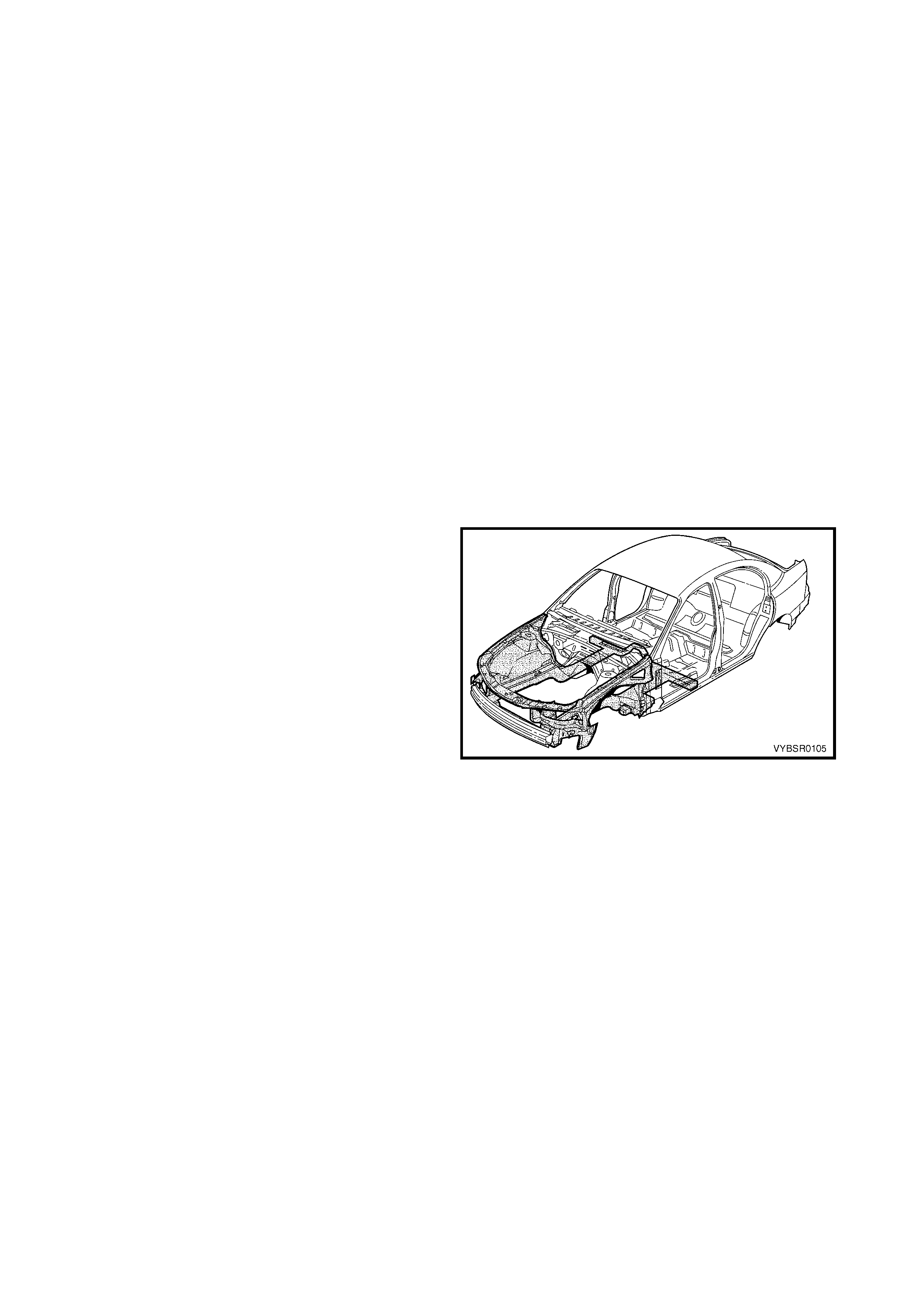
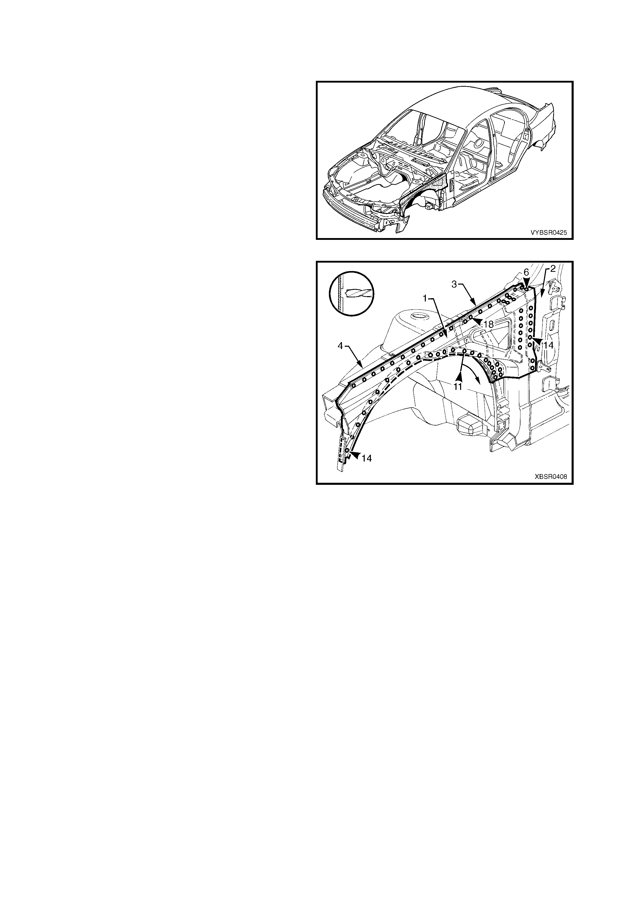
1.1 FRONT END COMPONENTS
The shaded components in Figure 4-1 are those dealt
with in this Section.
The components and assemblies shown in Figure 4-2
are the parts serviced for MY 2003 VY & V2 Series II
vehicles which form the basis of the repair procedures
in this Section. For a detailed view of the MY 2003 VY
& V2 Series II body components, refer to Section
3A (Sedan), 3B (Wagon), 3C (Utility) or 3D (Coupe).
NOTE: Always refer to your Authorised Retailer for
latest spare parts availability configurations.
Figure 4-1
Figure 4-2
Legend
1. Front End Panel Assembly
2. Headlamp Panel
3. Headlamp & Front Fascia Mount Bracket
4. Radiator Side Mounting Bracket
5. Front Wheelhouse Bracket Assembly
6. Front Bumper Impact Bar Bracket
7. Front Wheelhouse Panel Bracket
8. Radiator Lower Support Assembly
9. ABS Modulator Bracket Assembly
10. Horn Bracket Assembly
11. Front Wheelhouse Panel Assembly
12. Front Side Rail Assembly
13. Front Wheelhouse Panel Upper Side Rail
NOTE 1: Front end panel assembly (1) includes parts 2 & 3.
NOTE 2: Front side rail assembly (12) includes parts 4, 5, 6 and 7.
2. SERVICE OPERATIONS
2.1 FRONT END PANEL ASSEMBLY – REPLACE
REMOVE
1. Remove the adjacent bolt-on panels and
components as described in the appropriate
Section of the MY 2003 VY & V2 Series II Service
Information.
2. Remove the front bumper impact bar assembly,
refer to Section 3, 2. BUMPER IMPACT BAR
ASSEMBLIES.
3. If required, mount the vehicle on a suitable jig or
secure an appropriate tool between the two front
wheelhouse panels to maintain correct body
alignment when the front panel is removed.
Figure 4-3
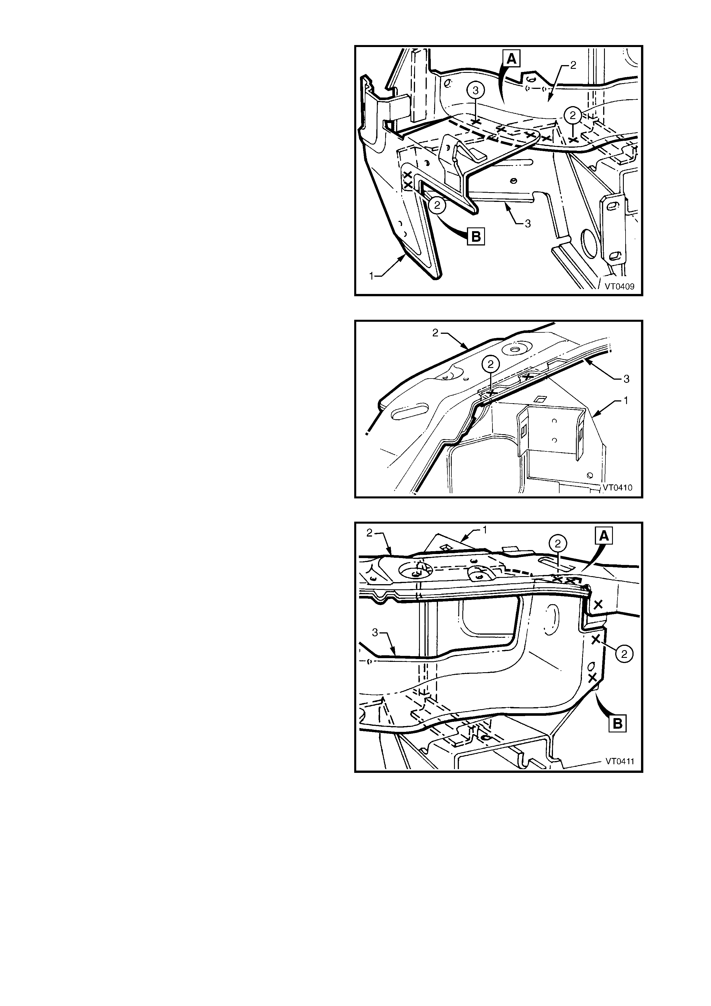
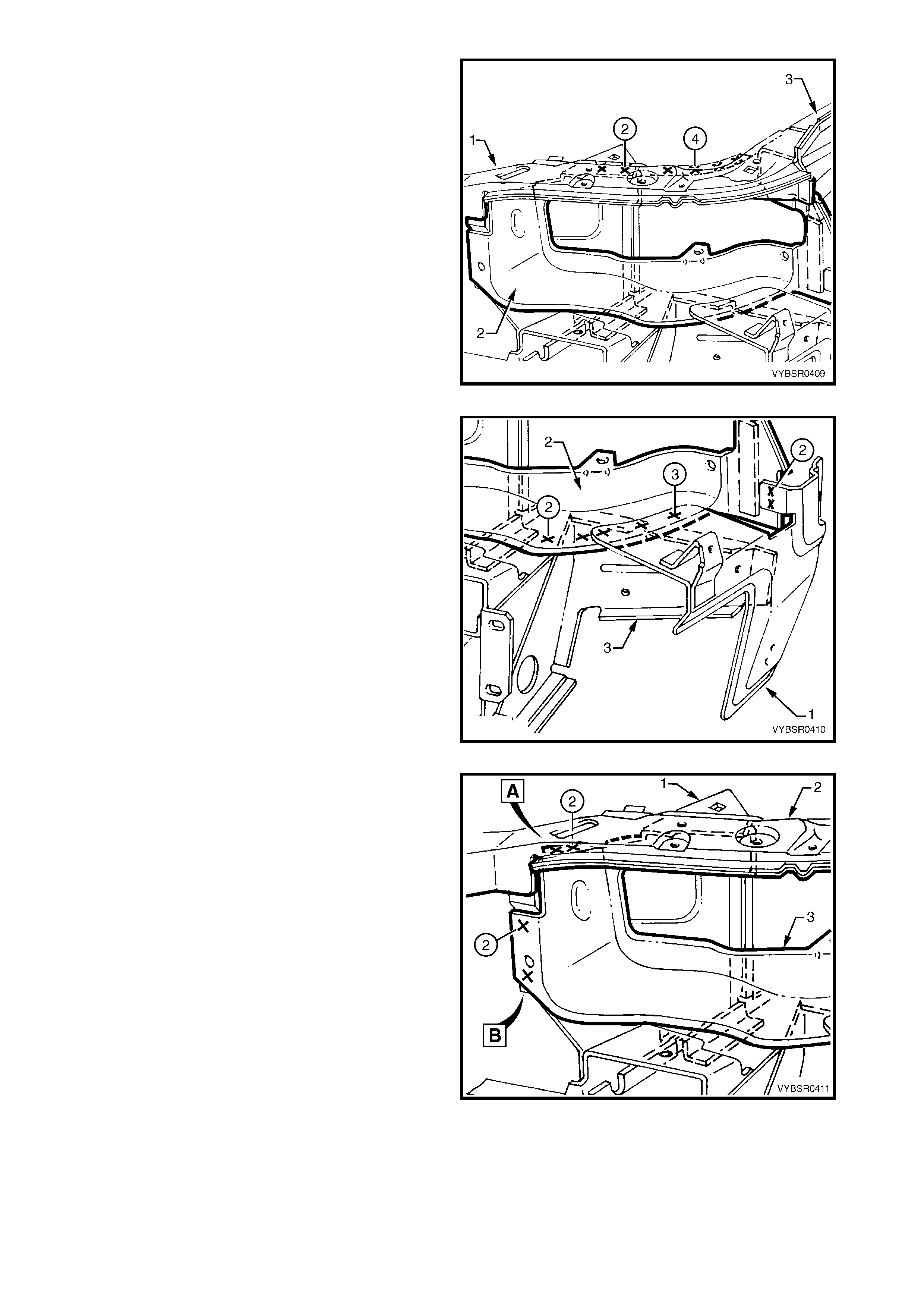
4. On each side of the vehicle, spot cut the welds
attaching the front end panel upper (1) to the front
wheelhouse panel (2). Four welds are on the
horizontal surface and two on the vertical flange.
Refer to weld group A.
5. Spot cut a total of 10 welds on each side of the
vehicle, attaching the headlamp panel (3) to the
front wheelhouse panel (2) and to the wheelhouse
upper side rail (4). Refer to weld group B.
Figure 4-4
6. On each side of the vehicle, spot cut the welds
attaching the front wheelhouse bracket assembly
(1) to the front end panel upper (2) and headlamp
panel (3). Refer to weld group A.
7. On each side of the vehicle, spot cut the three
welds on the vertical flange attaching the
headlamp panel and front end panel upper to the
front wheelhouse bracket assem bly. Refer to weld
group B.
Figure 4-5
8. On each side of the vehicle, spot cut the welds
attaching the front wheelhouse bracket assembly
(1) to the front end panel upper (2) and headlamp
panel (3).
Figure 4-6
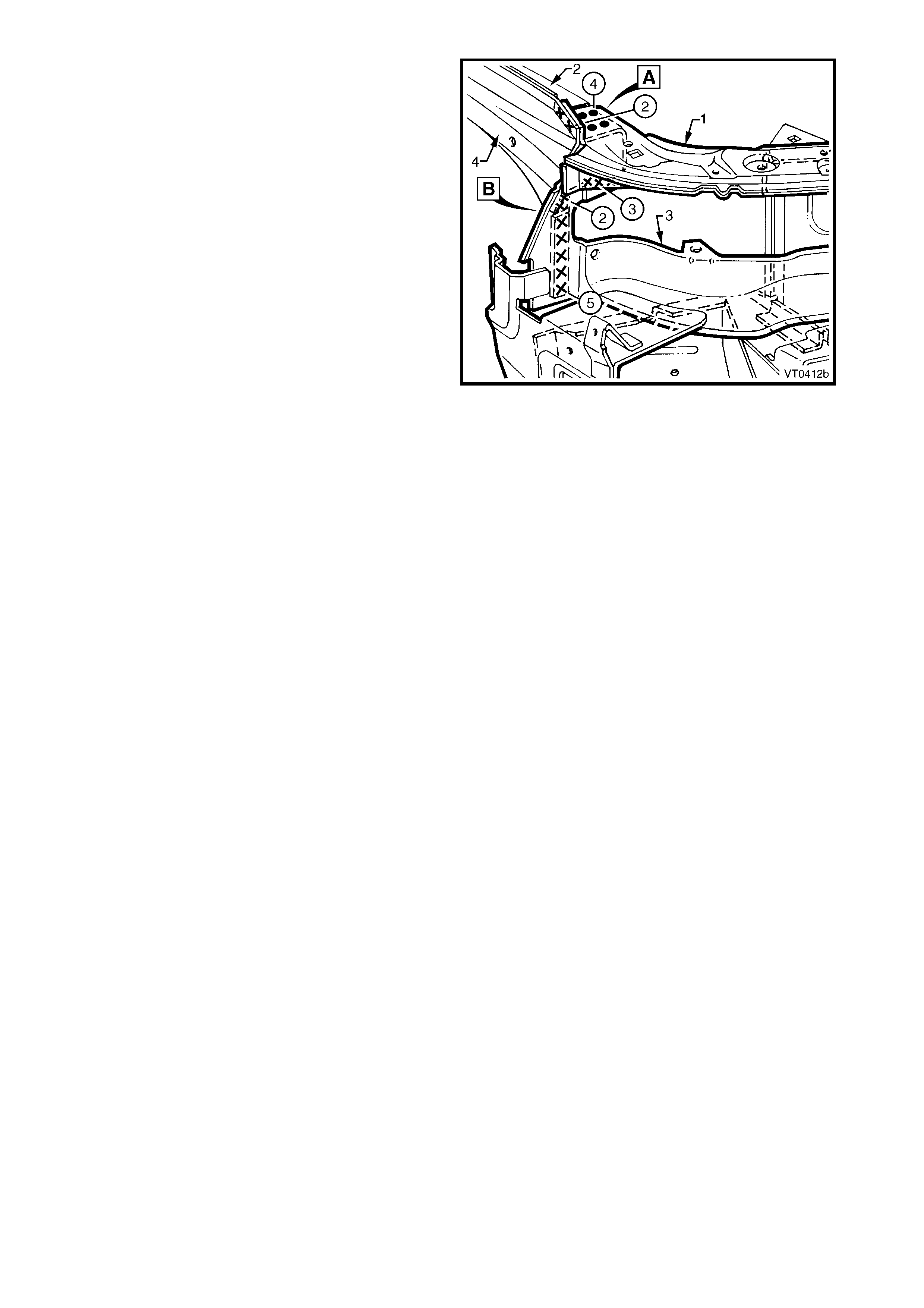
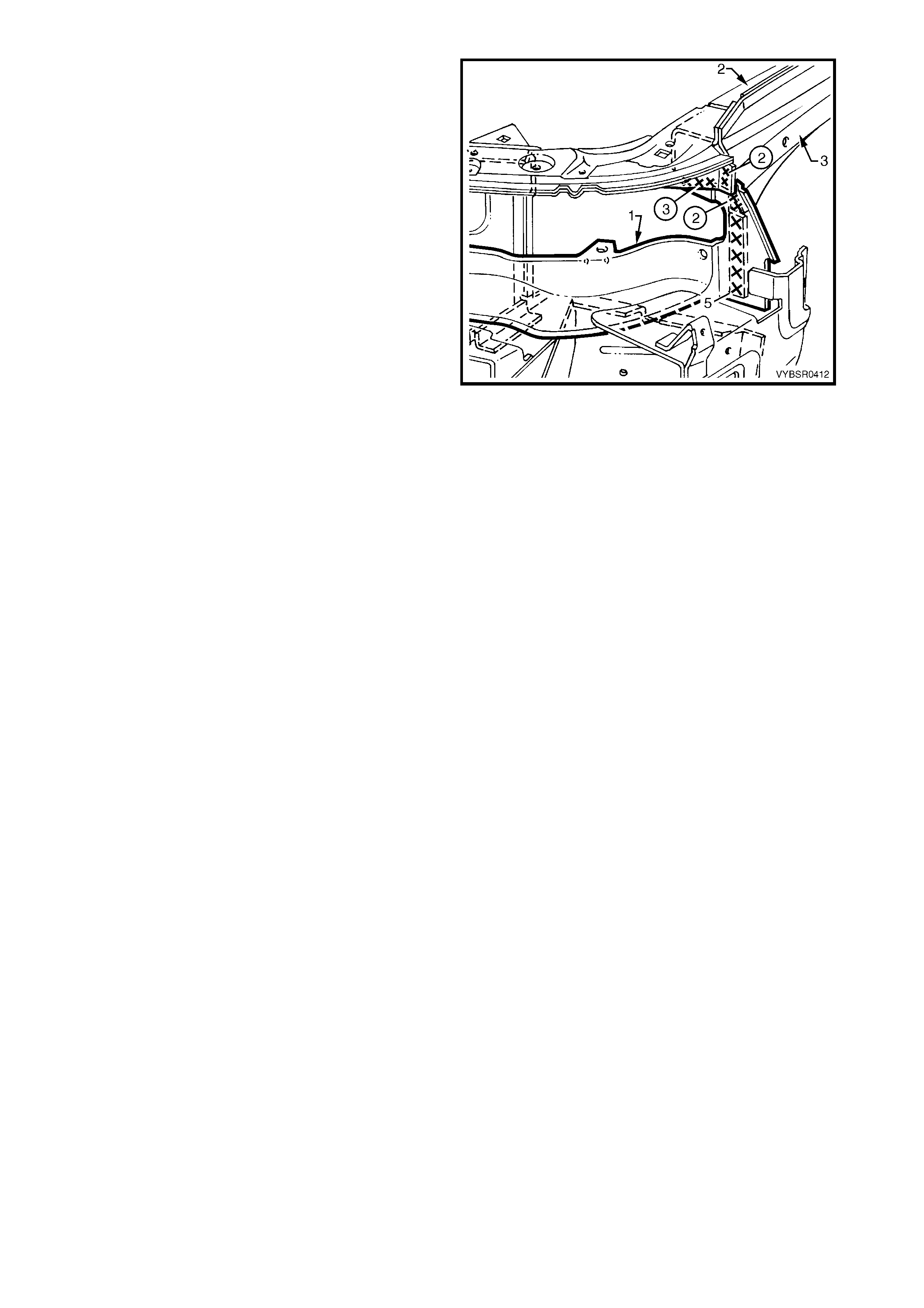
9. On each side of the vehicle, spot cut the welds
attaching the headlamp & front fascia mount
bracket (1) and headlamp panel (2) to the front
wheelhouse panel. Refer to weld group A.
10. Spot cut the two welds on each side of the vehicle
attaching the headlamp & front fascia mount
bracket to the front wheelhouse panel bracket (3).
Refer to weld group B.
11. Remove the complete front end panel assembly
from the vehicle and then repair any damage to
the adjacent parts as required.
12. Check and rectify the alignment of the body as
required, refer to 3. BODY DIMENSIONS in
Section 3A (Sedan), 3B (Wagon), 3C (Utility) or
3D (Coupe).
Figure 4-7
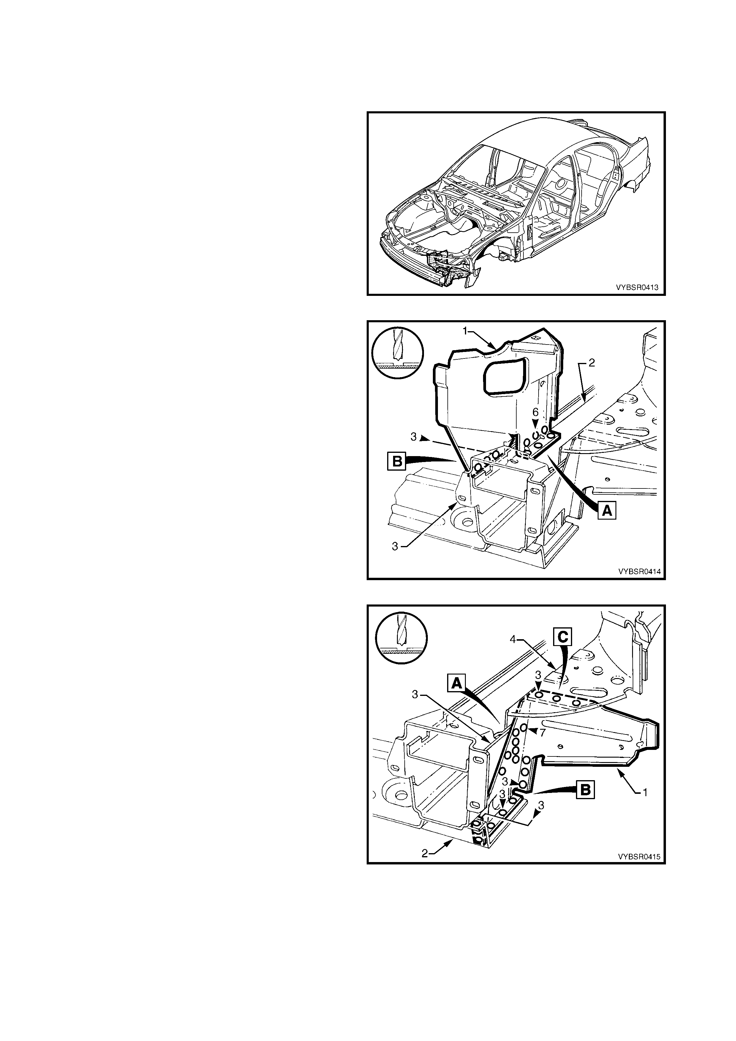
REPLACE
NOTE 1: Spot welding is the preferred method for attaching of panels and should be used whenever possible.
Where the spot welding equipment will not access the required weld position, a plug weld should be performed.
NOTE 2: The s ame number and pos ition of s pot welds (or plug welds) should be used when replac ing the panel,
as was used during manufacture, in order to maintain the original structural strength of the vehicle.
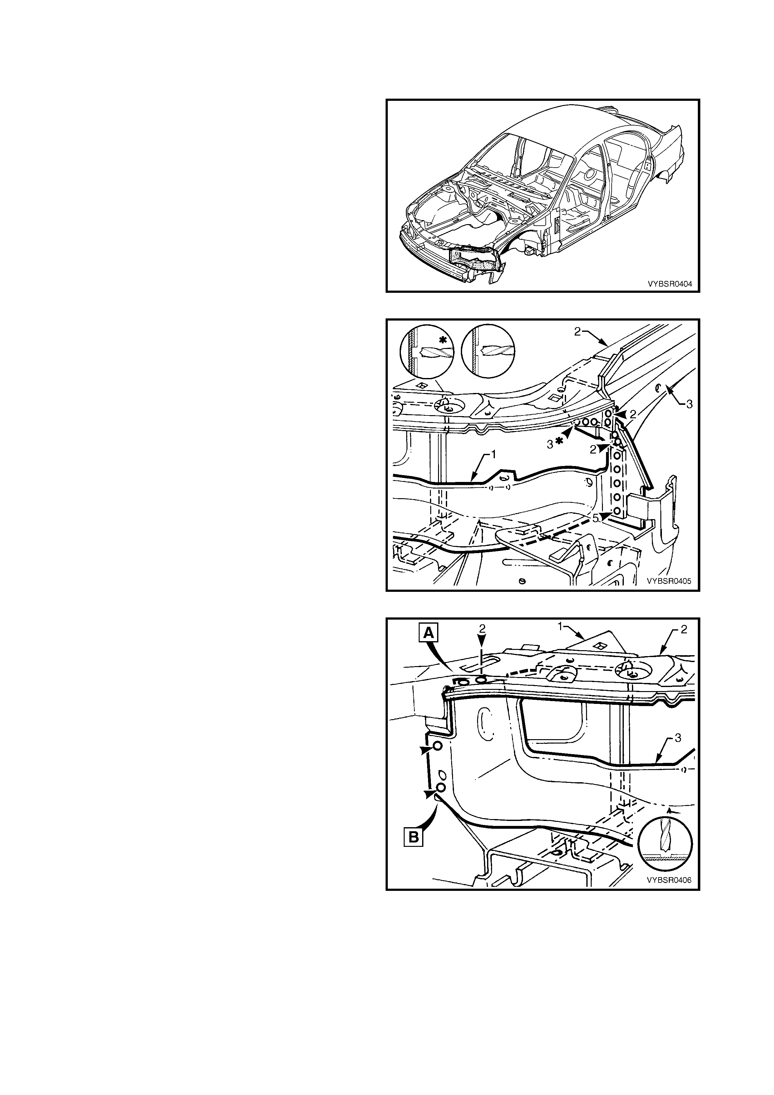
1. As required, mark the new panel with drilling locations in preparation for plug welding. Drill holes as required.
2. Prepare all mating surfaces and treat with Weld Through Primer (Item 1) as required, refer to 5. BODY
SEALING, ADHESIVES & DEADENERS in Section 3A (Sedan), 3B (Wagon), 3C (Utility) or 3D (Coupe).
3. Install the panel in position and secure with clamps.
4. Temporarily install the fenders and hood and
check the alignment and margins. Refer to
4. BODY MARGINS in Section 3A (Sedan),
3B (Wagon), 3C (Utility) or 3D (Coupe). Adjust
where necessary, and then remove fenders and
hood.
Figure 4-8
5. Spot weld the headlamp & front fascia mount
bracket (1) and headlamp panel (2) to the front
wheelhouse panel. Refer to weld group A.
6. Spot weld the headlamp & front fascia mount
bracket to the front wheelhouse panel bracket (3).
Refer to weld group B.
Figure 4-9
7. On each side of the vehicle, spot weld the front
wheelhouse bracket assembly (1) to the front end
panel upper (2) and headlamp panel (3).
Figure 4-10
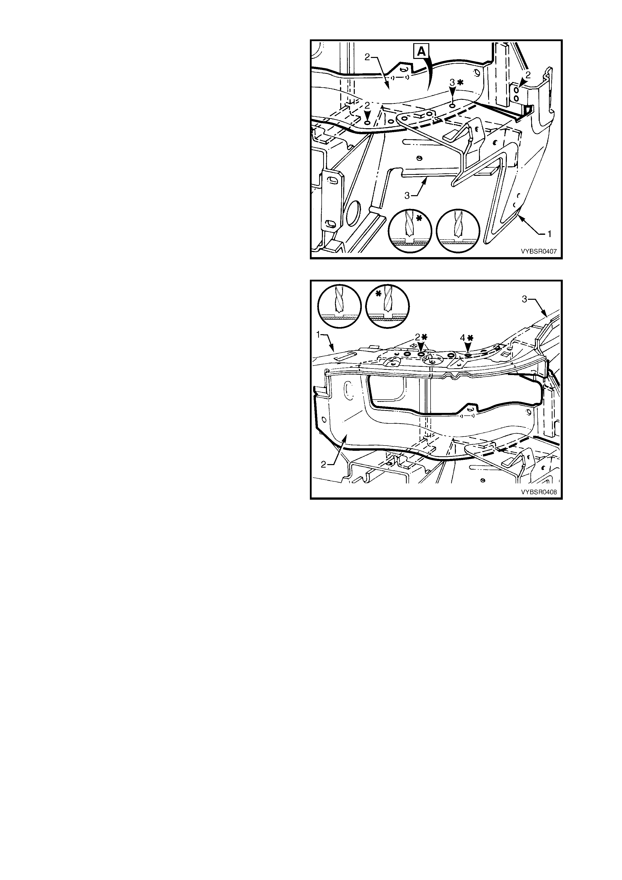
8. Spot weld in two places on each side of vehicle,
the front wheelhouse bracket assembly (1) to the
front end panel upper (2) and headlamp panel (3).
Refer to weld group A.
9. On each side of the vehicle, spot weld the
headlamp panel and the front end panel upper to
the front wheelhouse bracket assembly. Refer to
weld group B.
Figure 4-11
10. On each side of the vehicle, spot or plug weld
the front end panel upper (1) to the front
wheelhouse panel (2). Four welds are on the
horizontal surface and two on the vertical flange.
Refer to weld group A.
11. Weld a total of 10 places on each side of vehicle,
the headlamp panel (3) to the front wheelhouse
panel and the f ront wheelhouse upper side r ail (4).
Refer to weld group B.
12. Refinish and paint panels and other components
as required. Refer to Section 3, 1.3 PAINT
REFINISHING.
13. Apply Joint Sealer (Item 3) as required. Refer to
5. BODY SEALING, ADHESIVES & DEADENERS
in Section 3A (Sedan), 3B (Wagon), 3C (Utility)
or 3D (Coupe).
14. Apply Cavity Wax ( Item 8) as requir ed to the inside
of any box sections or areas inaccessible to paint,
refer to 6. CAVITY WAX in Section 3A (Sedan),
3B (Wagon), 3C (Utility) or 3D (Coupe).
15. Install the fr ont bumper impact bar assemb ly, refer
to Section 3, 2. BUMPER IMPACT BAR
ASSEMBLIES.
16. Install the remaining components as described in
the appropriate Section of the MY 2003 VY & V2
Series II Service Information.
Figure 4-12
2.2 HEADLAMP PANEL – REPLACE
REMOVE
1. Remove the adjacent bolt-on panels and
components as described in the appropriate
Section of the MY 2003 VY & V2 Series II Service
Information.
2. Remove the front bumper impact bar assembly,
refer to Section 3, 2. BUMPER IMPACT BAR
ASSEMBLIES.
Figure 4-13
3. Spot cut a total of 12 welds attaching the
headlamp panel (1) to the front wheelhouse panel
(2) and to the wheelhouse upper side rail (3).
Figure 4-14
4. Spot cut the welds attaching the front wheelhouse
bracket assembly (1) to the front end panel upper
(2) and headlamp panel (3). Refer to weld group A.
5. Spot cut the two welds on the vertical flange
attaching the headlamp panel to the front end
panel upper and front wheelhouse bracket
assembly. Refer to weld group B.
Figure 4-15
6. Spot cut the welds attaching the headlamp & front
fascia mount bracket (1) and headlamp panel (2)
to the front wheelhouse panel.
Figure 4-16
7. Spot cut the welds attaching the front end panel
upper (1) to the headlamp panel (2).
8. Remove the headlam p panel from the vehicle and
then repair any damage to the adjacent parts as
required.
9. Check and rectify the alignment of the body as
required, refer to 3. BODY DIMENSIONS in
Section 3A (Sedan), 3B (Wagon), 3C (Utility) or
3D (Coupe). Repair any damage to adjacent
panels.
Figure 4-17
REPLACE
NOTE 1: Spot welding is the preferred method for attaching of panels and should be used whenever possible.
Where the spot welding equipment available will not access the required weld position, a plug weld should be
performed.
NOTE 2: The s ame number and pos ition of s pot welds (or plug welds) should be used when replac ing the panel,
as was used during manufacture, in order to maintain the original structural strength of the vehicle.
1. As required, mark the new panels with drilling locations in preparation for plug welding. Drill holes as
required.
2. Prepare all mating surfaces and treat with Weld Through Primer (Item 1) as required, refer to 5. BODY
SEALING, ADHESIVES & DEADENERS in Section 3A (Sedan), 3B (Wagon), 3C (Utility) or 3D (Coupe).
3. Clamp the headlamp panel in position.
4. Spot or plug weld the front panel upper (1) to the
headlamp panel (2) and to the front fender skirt
(3).
Figure 4-18
5. Spot weld the headlamp & front fascia mount
bracket (1) and headlamp panel (2) to the front
wheelhouse panel.
Figure 4-19
6. Spot weld in two places, the front wheelhouse
bracket assembly (1) to the front end panel upper
(2) and headlamp panel (3). Refer to weld group A.
7. Spot weld the headlamp panel and the front end
panel upper to the front wheelhouse bracket
assembly. Refer to weld group B.
Figure 4-20
8. Spot weld a total of 12 places, the headlam p panel
(1) to the front wheelhouse panel (2) and the front
wheelhouse upper side rail (3).
9. Refinish and paint panels and other components
as required. Refer to Section 3, 1.3 PAINT
REFINISHING.
10. Apply Joint Sealer (Item 3) as required. Refer to
5. BODY SEALING, ADHESIVES & DEADENERS
in Section 3A (Sedan), 3B (Wagon), 3C (Utility)
or 3D (Coupe).
11. Apply Cavity Wax (Item 8) as r equired to the inside
of any box sections or areas inaccessible to paint,
refer to 6. CAVITY WAX in Section 3A (Sedan),
3B (Wagon), 3C (Utility) or 3D (Coupe).
12. Install the fr ont bumper impact bar assemb ly, refer
to Section 3, 2. BUMPER IMPACT BAR
ASSEMBLIES.
13. Install the remaining components as described in
the appropriate Section of the MY 2003 VY & V2
Series II Service Information.
Figure 4-21
2.3 FRONT WHEELHOUSE BRACKET ASSEMBLY, FRONT WHEELHOUSE BRACKET &
FRONT BUMPER IMPACT BAR BRACKET ASSEMBLY – REPLACE
REMOVE
1. Remove the adjacent bolt-on panels and
components as described in the appropriate
Section of the MY 2003 VY & V2 Series II Service
Information.
2. Remove the front bumper impact bar assembly,
refer to Section 3, 2. BUMPER IMPACT BAR
ASSEMBLIES.
3. Remove the adjoining panels as required.
Figure 4-22
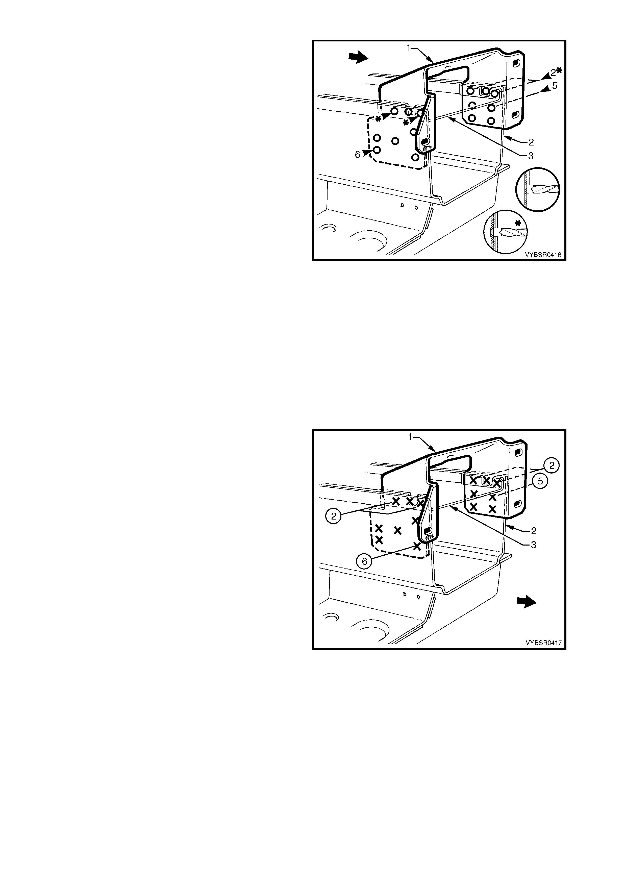
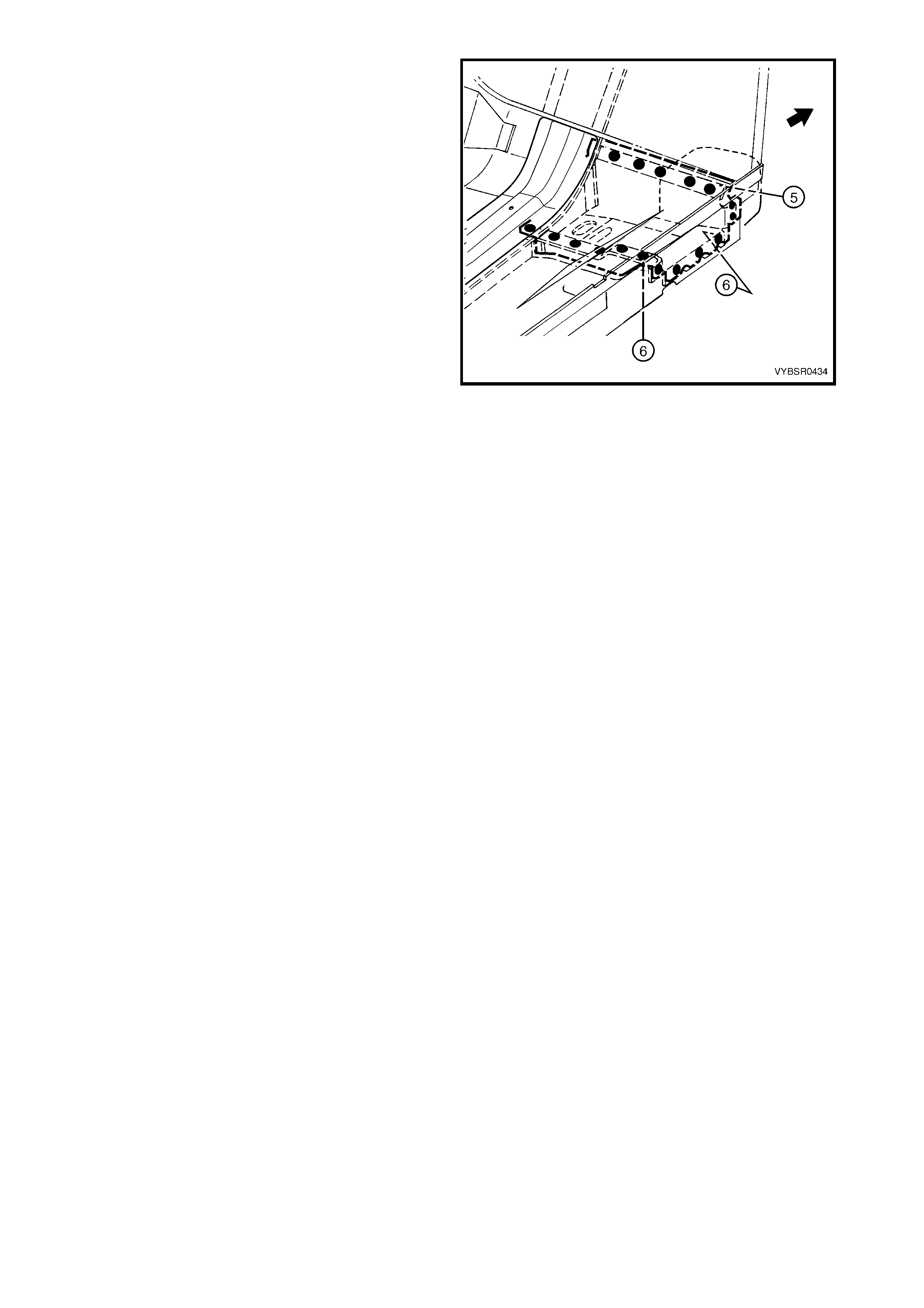
4. Spot cut the six welds attaching the front
wheelhouse bracket assembly (1) to the front side
rail (2). Refer to weld group A.
5. Spot cut the three welds attaching the front
wheelhouse bracket assembly (1) to the front
bumper impact bar bracket (3). Refer to weld
group B.
6. Remove the front wheelhouse bracket assembly.
Figure 4-23
7. Spot cut the welds attaching the front wheelhouse
panel bracket (1) to the front side rail (3). Refer to
weld group A.
8. Spot cut the welds attaching the front wheelhouse
panel bracket to the radiator lower support
assembly (2). Refer to weld group B.
9. Spot cut the three welds attaching the front
wheelhouse panel brack et to the front wheelhouse
panel (4). Refer to weld group C.
10. Remove the front wheelhouse panel bracket.
Figure 4-24
11. Spot cut the welds attac hing each side of the front
bumper im pact bar brac ket (1) to the f ront side rail
(2).
12. Prise front bumper impact bar bracket out from
between the front side rail and the front side rail
closing plate (3).
13. Repair any damage to adjacent panels.
14. Check and rectify the alignment of the body as
required, refer to 3. BODY DIMENSIONS in
Section 3A (Sedan), 3B (Wagon), 3C (Utility) or
3D (Coupe).
Figure 4-25
REPLACE
NOTE 1: Spot welding is the preferred method for attaching of panels and should be used whenever possible.
Where the spot welding equipment available will not access the required weld position, a plug weld should be
performed.
NOTE 2: The s ame number and pos ition of s pot welds (or plug welds) should be used when replac ing the panel,
as was used during manufacture, in order to maintain the original structural strength of the vehicle.
1. As required, mark the new panel with drilling locations in preparation for plug welding. Drill holes as required.
2. Prepare all mating surfaces and treat with Weld Through Primer (Item 1) as required, refer to 5. BODY
SEALING, ADHESIVES & DEADENERS in Section 3A (Sedan), 3B (Wagon), 3C (Utility) or 3D (Coupe).
3. Clamp the panels in position and test fit the front bumper impact bar.
4. Spot weld each side of the front bumper impact
bar mounting bracket (1) to front side rail (2).
Figure 4-26
5. Spot weld the front wheelhouse panel bracket (1)
to the front side rail (3). Refer to weld group A.
6. Spot weld the front wheelhouse panel bracket to
the radiator lower support assembly (2). Refer to
weld group B.
7. Spot weld the front wheelhouse panel bracket to
the front wheelhouse panel (4). Refer to weld
group C.
Figure 4-27
8. Plug weld the front wheelhouse bracket assembly
(1) to the front side rail (2). Refer to weld group A.
9. Spot weld the front wheelhouse bracket assembly
to the front bumper impact bar bracket (3). Refer
to weld group B.
10. Replace the any removed panels as required.
11. Refinish and paint panels and other components
as required. Refer to Section 3, 1.3 PAINT
REFINISHING.
12. Apply Joint Sealer (Item 3) as required. Refer to
5. BODY SEALING, ADHESIVES & DEADENERS
in Section 3A (Sedan), 3B (Wagon), 3C (Utility)
or 3D (Coupe).
13. Apply Cavity Wax ( Item 8) as requir ed to the inside
of any box sections or areas inaccessible to paint,
refer to 6. CAVITY WAX in Section 3A (Sedan),
3B (Wagon), 3C (Utility) or 3D (Coupe).
14. Install the fr ont bumper impact bar assemb ly, refer
to Section 3, 2. BUMPER IMPACT BAR
ASSEMBLIES.
15. Install the remaining components as described in
the appropriate Section of the MY 2003 VY & V2
Series II Service Information.
Figure 4-28
2.4 RADIATOR LOWER SUPPORT ASSEMBLY – REPLACE
REMOVE
1. Remove the adjacent bolt-on panels and
components as described in the appropriate
Section of the MY 2003 VY & V2 Series II Service
Information.
2. Remove the front bumper impact bar assembly,
refer to Section 3, 2. BUMPER IMPACT BAR
ASSEMBLIES.
3. If required, mount the vehicle on a suitable jig or
secure an appropriate tool between the two front
side rails to m aintain correct body alignment when
the radiator lower support assembly is removed.
Figure 4-29
4. On both sides of the vehicle, spot cut nine welds
attaching the fr ont wheelhouse panel brac ket (1) to
the radiator lower support assembly (2).
Figure 4-30
5. From underneath the vehicle, spot cut the six
welds attaching the radiator lower support
assembly (1) to each front side rail (2).
NOTE: Access is available to the two centre spot
welds through the hole on the underside of the
support.
6. Remove the radiator lower support assembly from
the vehicle.
Figure 4-31
REPLACE
NOTE 1: Spot welding is the preferred method for attaching of panels and should be used whenever possible.
Where the spot welding equipment available will not access the required weld position, a plug weld should be
performed.
NOTE 2: The s ame number and pos ition of s pot welds (or plug welds) should be used when replac ing the panel,
as was used during manufacture, in order to maintain the original structural strength of the vehicle.
1. As required, mark the new panel with drilling locations in preparation for plug welding. Drill holes as required.
2. Prepare all mating surfaces and treat with Weld Through Primer (Item 1) as required, refer to 5. BODY
SEALING, ADHESIVES & DEADENERS in Section 3A (Sedan), 3B (Wagon), 3C (Utility) or 3D (Coupe).
3. Clamp the radiator lower support assembly (1) in
position on the front side rails (2) and spot or plug
weld in place.
Figure 4-32
4. Spot weld nine places , the front wheelhouse panel
bracket (1) to the radiator lower support assembly
(2).
5. Refinish and paint panels and other components
as required. Refer to Section 3, 1.3 PAINT
REFINISHING.
6. Apply Joint Sealer (Item 3) as required. Refer to
5. BODY SEALING, ADHESIVES & DEADENERS
in Section 3A (Sedan), 3B (Wagon), 3C (Utility)
or 3D (Coupe).
7. Apply Cavity Wax (Item 8) as r equired to the inside
of any box sections or areas inaccessible to paint,
refer to 6. CAVITY WAX in Section 3A (Sedan),
3B (Wagon), 3C (Utility) or 3D (Coupe).
8. Install the fr ont bumper impact bar assembly, refer
to Section 3, 2. BUMPER IMPACT BAR
ASSEMBLIES.
9. Install the remaining components as described in
the appropriate Section of the MY 2003 VY & V2
Series II Service Information.
Figure 4-33
2.5 FRONT WHEELHOUSE PANEL UPPER SIDE RAIL – REPLACE
REMOVE
1. Remove the adjacent bolt-on panels and
components as described in the appropriate
Section of the MY 2003 VY & V2 Series II Service
Information.
2. Remove the front bumper impact bar assembly,
refer to Section 3, 2. BUMPER IMPACT BAR
ASSEMBLIES.
3. As required, remove front end panel assembly or
spot cut the welds attaching the side rail to the
front end panel assembly, refer to 2.1 FRONT
END PANEL ASSEMBLY – REPLACE.
Figure 4-34
4. Spot cut the welds attaching the front wheelhouse
panel upper s ide rail (1) to the door opening f ram e
assem bly (2), hinge pillar inner panel assem bly (3)
and front wheelhouse panel assembly (4) and
remove the upper side rail.
Figure 4-35
REPLACE
NOTE 1: Spot welding is the preferred method for attaching of panels and should be used whenever possible.
Where the spot welding equipment available will not access the required weld position, a plug weld should be
performed.
NOTE 2: The s ame number and pos ition of s pot welds (or plug welds) should be used when replac ing the panel,
as was used during manufacture, in order to maintain the original structural strength of the vehicle.
1. As required, mark the new panel with drilling locations in preparation for plug welding. Drill holes as required.
2. Prepare all mating surfaces and treat with Weld Through Primer (Item 1) as required, refer to 5. BODY
SEALING, ADHESIVES & DEADENERS in Section 3A (Sedan), 3B (Wagon), 3C (Utility) or 3D (Coupe).
3. Clamp the front wheelhouse panel upper side rail in position.
4. Spot or plug weld the front wheelhouse panel
upper side rail (1) to the door opening frame
assem bly (2), hinge pillar inner panel assem bly (3)
and front wheelhouse panel assembly (4).
5. As required, replace the front end panel assembly
or spot or plug weld the side rail to the front end
panel assembly, refer to 2.1 FRONT END PANEL
ASSEMBLY – REPLACE.
6. Refinish and paint panels and other components
as required. Refer to Section 3, 1.3 PAINT
REFINISHING.
7. Apply Joint Sealer (Item 3) as required. Refer to
5. BODY SEALING, ADHESIVES & DEADENERS
in Section 3A (Sedan), 3B (Wagon), 3C (Utility)
or 3D (Coupe).
8. Apply Cavity Wax ( Item 8) as requir ed to the inside
of any box sections or areas inaccessible to paint,
refer to 6. CAVITY WAX in Section 3A (Sedan),
3B (Wagon), 3C (Utility) or 3D (Coupe).
Figure 4-36
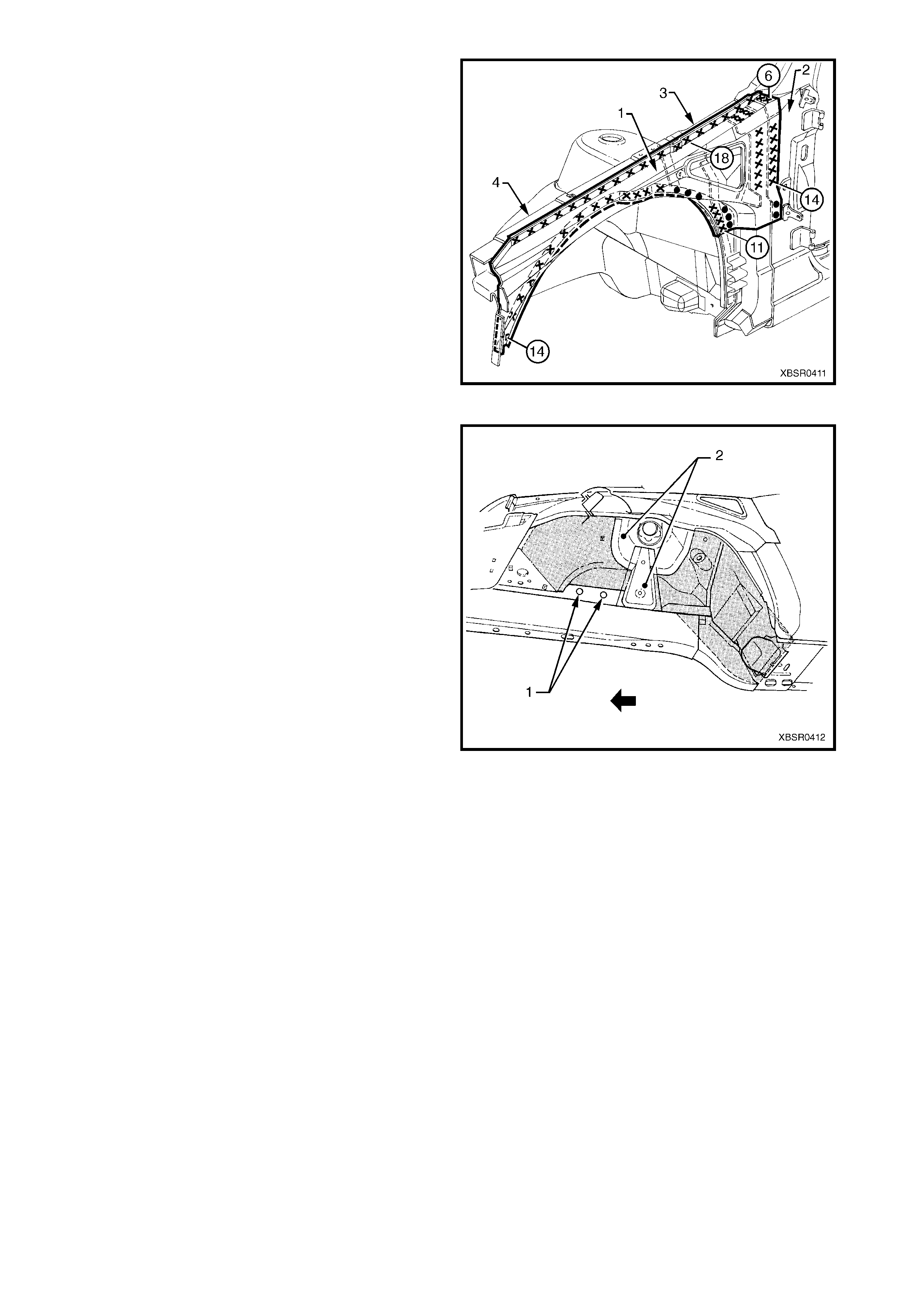
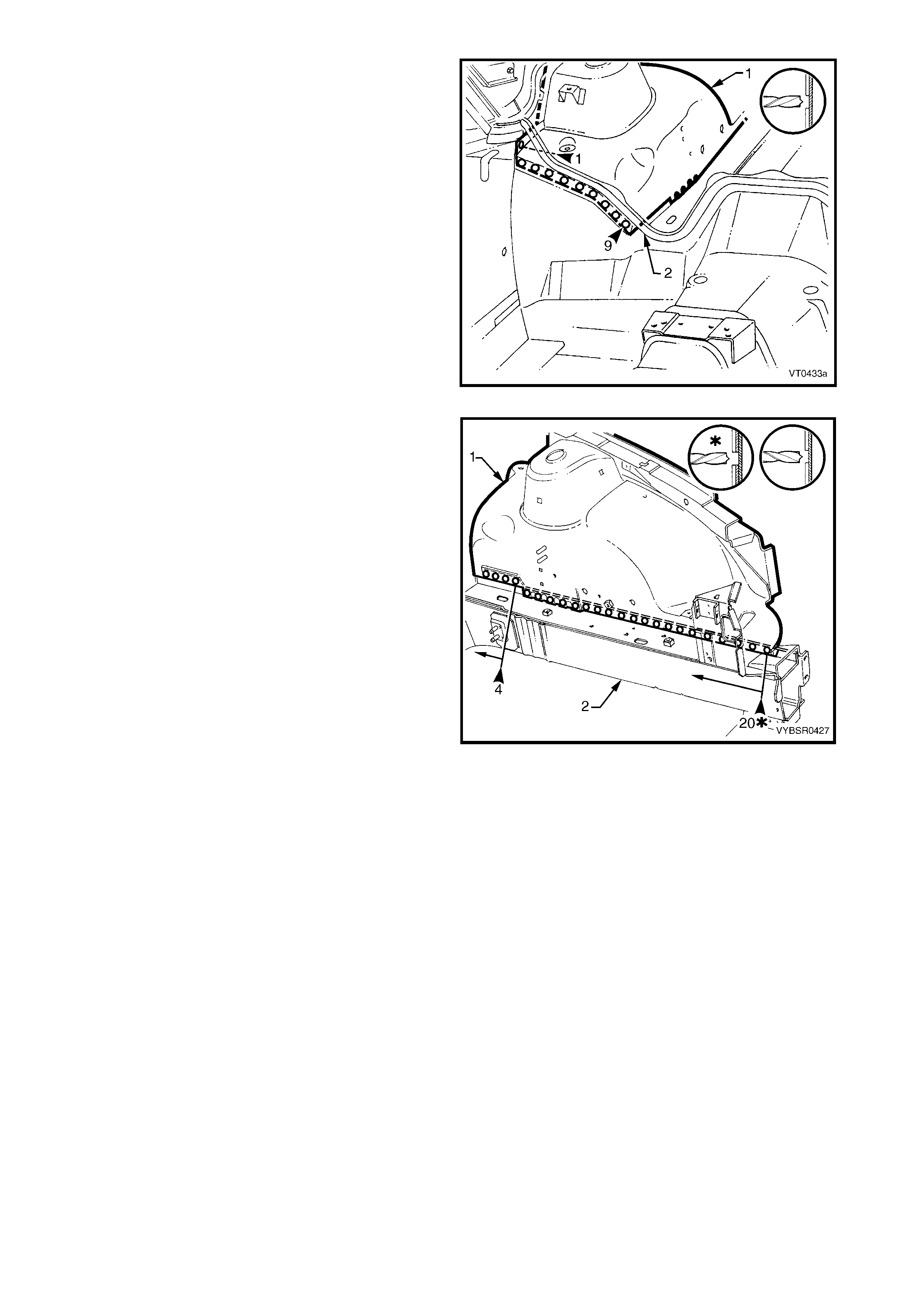
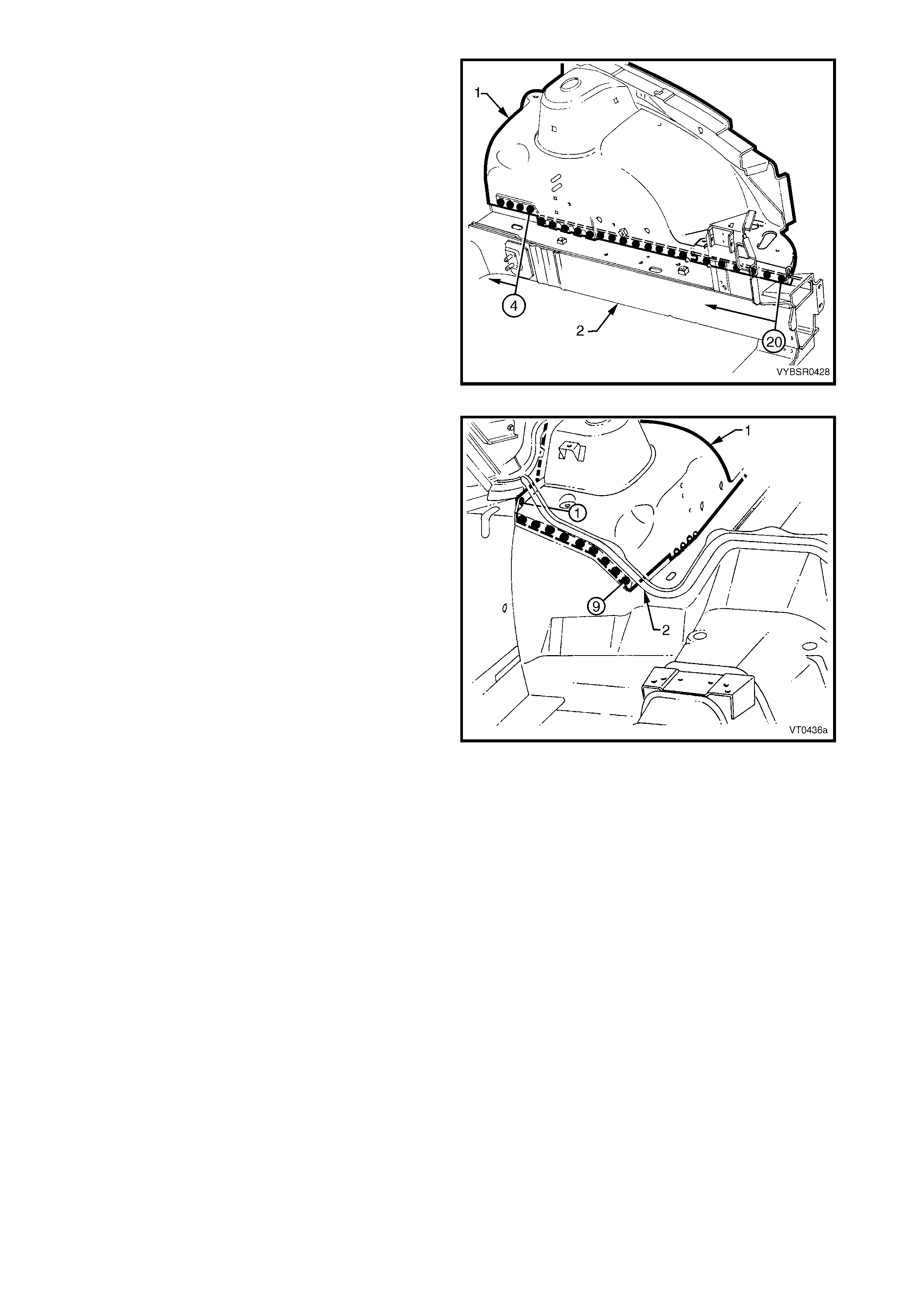
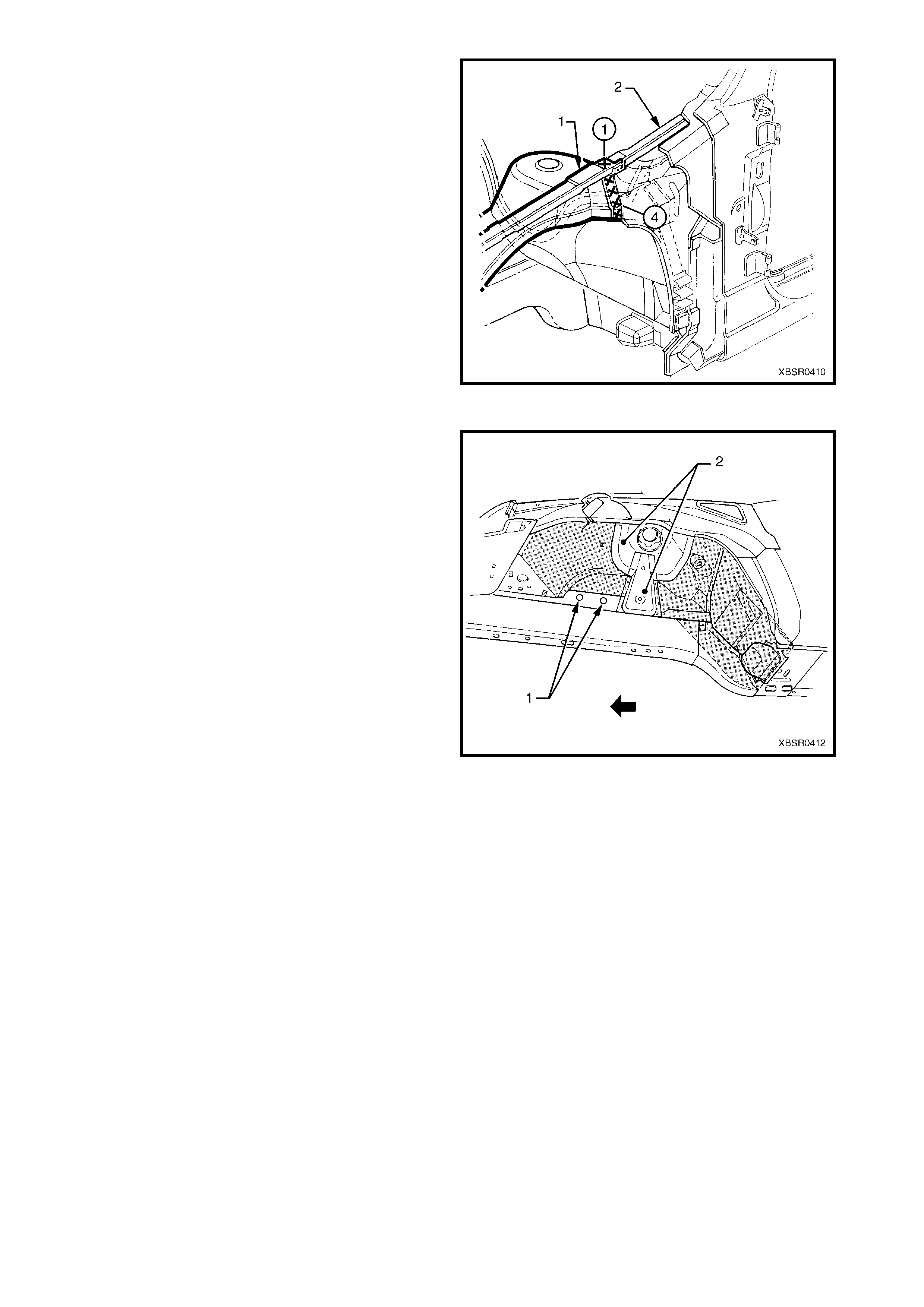
9. Apply Spray-on Deadener (Item 7) to the wheel
side of front wheelhouse panel assem bly. Refer to
5. BODY SEALING, ADHESIVES & DEADENERS
in Section 3A (Sedan), 3B (Wagon), 3C (Utility)
or 3D (Coupe).
NOTE: Keep the area around brake pipe holes (1)
clear of deadener. Over spray of deadener is
permissible on the strut tower reinforcement and front
suspension strut tower (2).
10. Install the fr ont bumper impact bar assemb ly, refer
to Section 3, 2. BUMPER IMPACT BAR
ASSEMBLIES.
11. Install the remaining components as described in
the appropriate Section of the MY 2003 VY & V2
Series II Service Information.
Figure 4-37
2.6 FRONT WHEELHOUSE PANEL ASSEMBLY – REPLACE
REMOVE
1. Remove the adjacent bolt-on panels and
components as described in the appropriate
Section of the MY 2003 VY & V2 Series II Service
Information.
2. Remove the front bumper impact bar assembly,
refer to Section 3, 2. BUMPER IMPACT BAR
ASSEMBLIES.
3. If required, mount the vehicle on a suitable jig or
secure an appropriate tool between the front side
rails to maintain correct body alignment when the
front end panel assembly is removed.
4. Remove front end panel assembly, refer to
2.1 FRONT END PANEL ASSEMBLY –
REPLACE.
5. Remove the welds attaching the front wheelhouse
panel bracket to the front wheelhouse, refer to
2.3 FRONT WHEELHOUSE BRACKET
ASSEMBLY, FRONT WHEELHOUSE BRACKET
& FRONT BUMPER IMPACR BAR BRACKET
ASSEMBLY – REPLACE.
6. Remove the front wheelhouse panel upper side
rail, refer to 2.5 FRONT WHEELHOUSE PANEL
UPPER SIDE RAIL – REPLACE.
Figure 4-38
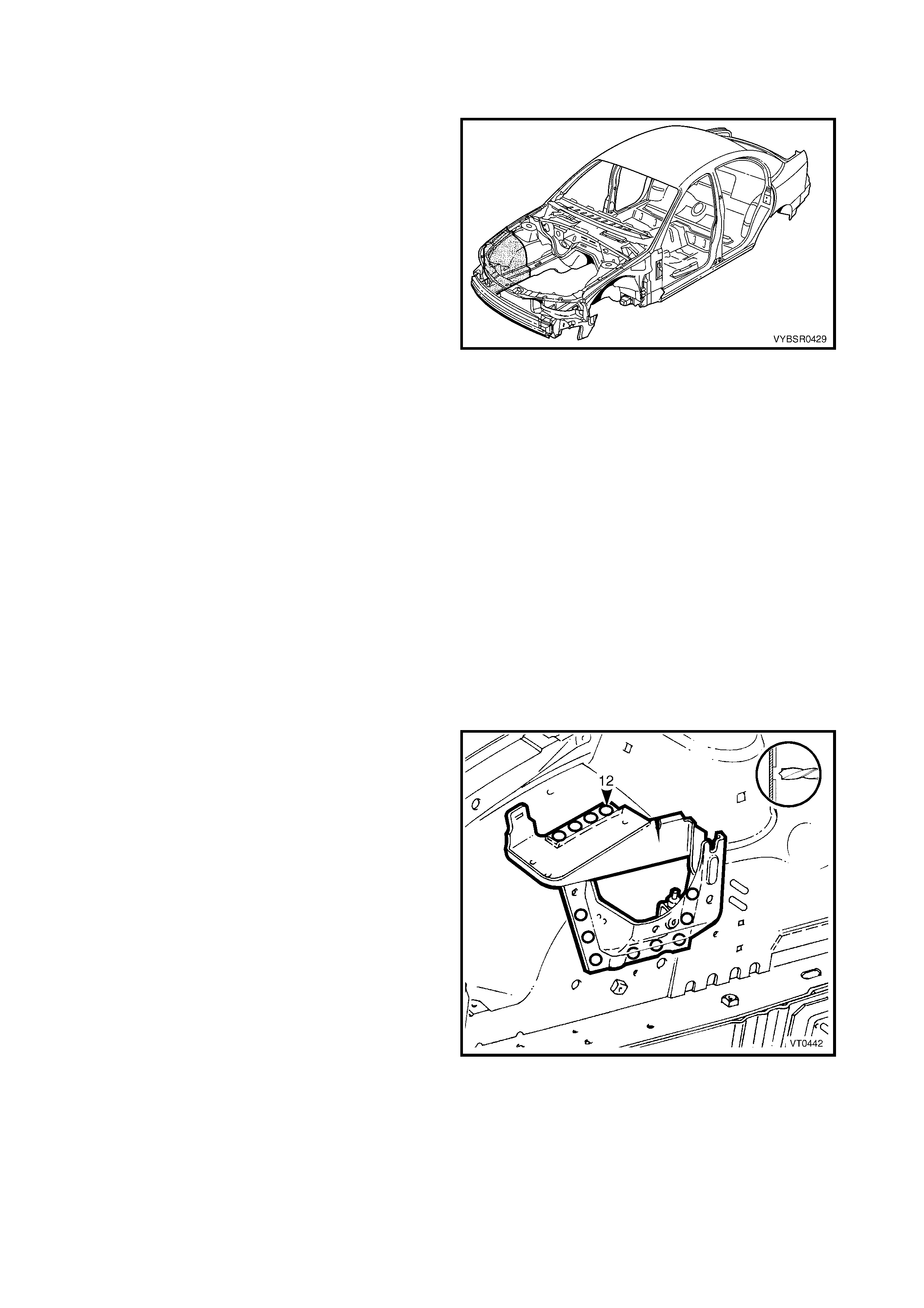
7. Spot cut the welds attaching the front wheelhouse
panel assembly (1) to the hinge pillar inner panel
assembly (2).
Figure 4-39
8. Spot cut the welds attaching the front wheelhouse
panel assembly (1) to the front floor panel
extension (2).
NOTE: The dash panel assembly is not shown for
clarity.
9. Spot cut the weld attaching the front wheelhouse
panel assembly (1) to the hinge pillar inner panel
assembly.
Figure 4-40
10. Spot cut the welds attaching the front wheelhouse
panel assembly (1) to the front side rail (2).
11. Remove front wheelhouse panel assembly and
repair any adjacent damaged panels as required.
12. Check and rectify the alignment of the body as
required, refer to 3. BODY DIMENSIONS in
Section 3A (Sedan), 3B (Wagon), 3C (Utility) or
3D (Coupe).
Figure 4-41
REPLACE
NOTE 1: Spot welding is the preferred method for attaching of panels and should be used whenever possible.
Where the spot welding equipment available will not access the required weld position, a plug weld should be
performed.
NOTE 2: The s ame number and pos ition of s pot welds (or plug welds) should be used when replac ing the panel,
as was used during manufacture, in order to maintain the original structural strength of the vehicle.
1. As required, mark the new panel with drilling locations in preparation for plug welding. Drill holes as required.
2. Prepare all mating surfaces and treat with Weld Through Primer (Item 1) as required, refer to 5. BODY
SEALING, ADHESIVES & DEADENERS in Section 3A (Sedan), 3B (Wagon), 3C (Utility) or 3D (Coupe).
3. Clamp the front wheelhouse panel assembly in position and confirm its location by checking the vehicle body
dimensions, refer to 3. BODY DIMENSIONS in Section 3A (Sedan), 3B (Wagon), 3C (Utility) or
3D (Coupe). Additionally, the front fender and engine hood may be fitted to confirm margins.
4. Plug weld the front wheelhouse panel assembly (1)
to the front side rail (2).
Figure 4-42
5. Plug weld the front wheelhouse panel assembly (1)
to the f ront floor panel extens ion (2) and the hinge
pillar inner panel assembly.
Figure 4-43
6. Spot weld the front wheelhouse panel assembly
(1) to the hinge pillar inner panel assembly (2).
7. Replace the front wheelhouse panel upper side
rail, refer to 2.5 FRONT WHEELHOUSE PANEL
UPPER SIDE RAIL.
8. Replace the front end panel assembly, refer to
2.1 FRONT END PANEL ASSEMBLY –
REPLACE.
9. Refinish and paint panels and other components
as required. Refer to Section 3, 1.3 PAINT
REFINISHING.
10. Apply J oint Sealer (Item 3) as required. Ref er to 5.
BODY SEALING, ADHESIVES & DEADENERS in
Section 3A (Sedan), 3B (Wagon), 3C (Utility) or
3D (Coupe).
11. Apply Cavity Wax ( Item 8) as requir ed to the inside
of any box sections or areas inaccessible to paint,
refer to 6. CAVITY WAX in Section 3A (Sedan),
3B (Wagon), 3C (Utility) or 3D (Coupe).
Figure 4-44
12. Apply Spray-on Deadener (Item 7) to the wheel
side of front wheelhouse panel assem bly. Refer to
5. BODY SEALING, ADHESIVES & DEADENERS
in Section 3A (Sedan), 3B (Wagon), 3C (Utility)
or 3D (Coupe).
NOTE: Keep the area around brake pipe holes (1)
clear of deadener. Over spray of deadener is
permissible on the strut tower reinforcement and front
suspension strut tower (2).
12. Install the fr ont bumper impact bar assemb ly, refer
to Section 3, 2. BUMPER IMPACT BAR
ASSEMBLIES.
13. Install the remaining components as described in
the appropriate Section of the MY 2003 VY & V2
Series II Service Information.
Figure 4-45
2.7 FRONT WHEELHOUSE PANEL & FRONT SIDE RAIL – PARTIAL REPLACE
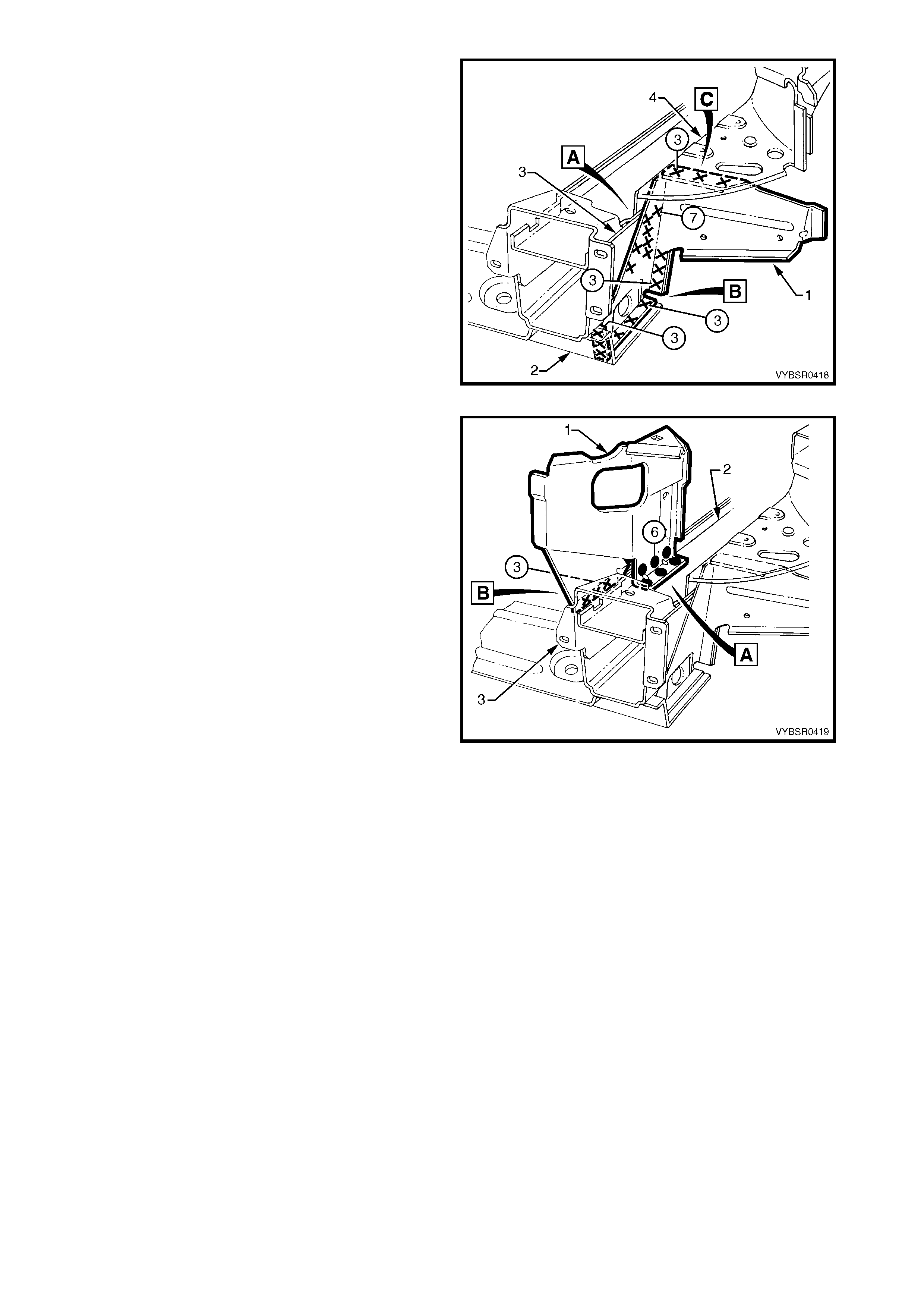
REMOVE
NOTE: The integrity of the front side rails is critical to
the function of the occupant protection system. If the
rails are incorrectly repaired following damage, it is
possible the seatbelt pretensioner and airbag system
will not function as intended, allowing incorrect
deployment.
IMPORTANT: If significant creasing or crumple of the
front side rail has occurred and continues rearward of
the front suspension crossmember, the full front side
rail as sem bly m ust be replac ed. Refer to 1. GENERAL
DESCRIPTION for further information.
1. Remove the adjacent bolt-on panels and
components as described in the appropriate
Section of the MY 2003 VY & V2 Series II Service
Information.
2. Remove the front bumper impact bar assembly,
refer to Section 3, 2. BUMPER IMPACT BAR
ASSEMBLIES.
Figure 4-46
3. Either m ount the vehic le on a suitable jig or secure
an appropriate tool between the front side rails to
maintain correct body alignment when the front
end panel assembly is removed.
4. Remove the front end panel assembly, refer to
2.1 FRONT PANEL – REPLACE.
5. Remove the front wheelhouse panel upper
side rail on the damaged side, refer to
2.5 FRONT WHEEL HOUSE PANEL UPPER SIDE
RAIL – REPLACE .
6. Either detach one side, or remove completely, the
radiator lower support assembly, refer to
2.4 RADIATOR LOWER SUPPORT ASSEMBLY
– REPLACE.
7. If the damage is on the right-hand side of the
vehicle, the front wheelhouse panel will be cut
through the position of the ABS m odulator bracket
assembly. In this cas e, r emove the brac ket by spot
cutting the welds attaching it to the front
wheelhouse panel.
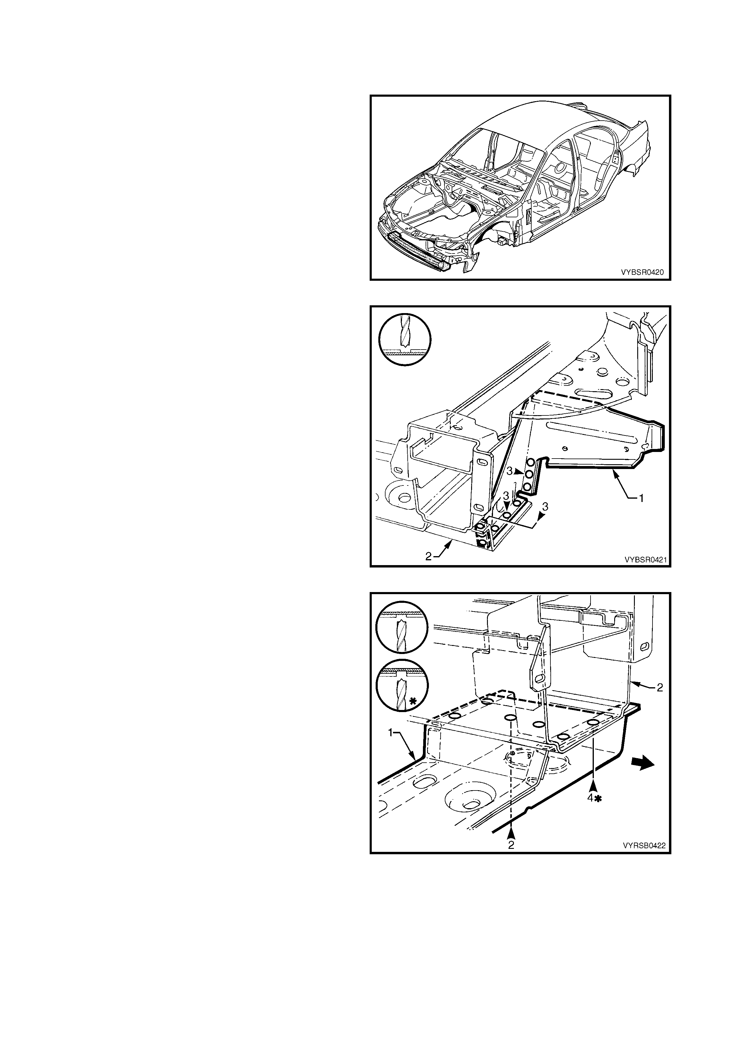
Figure 4-47
8. Rough cut the damaged front wheelhouse panel
and f ront s ide rail, leaving enough mater ial to allow
the final cut lines to be completed.
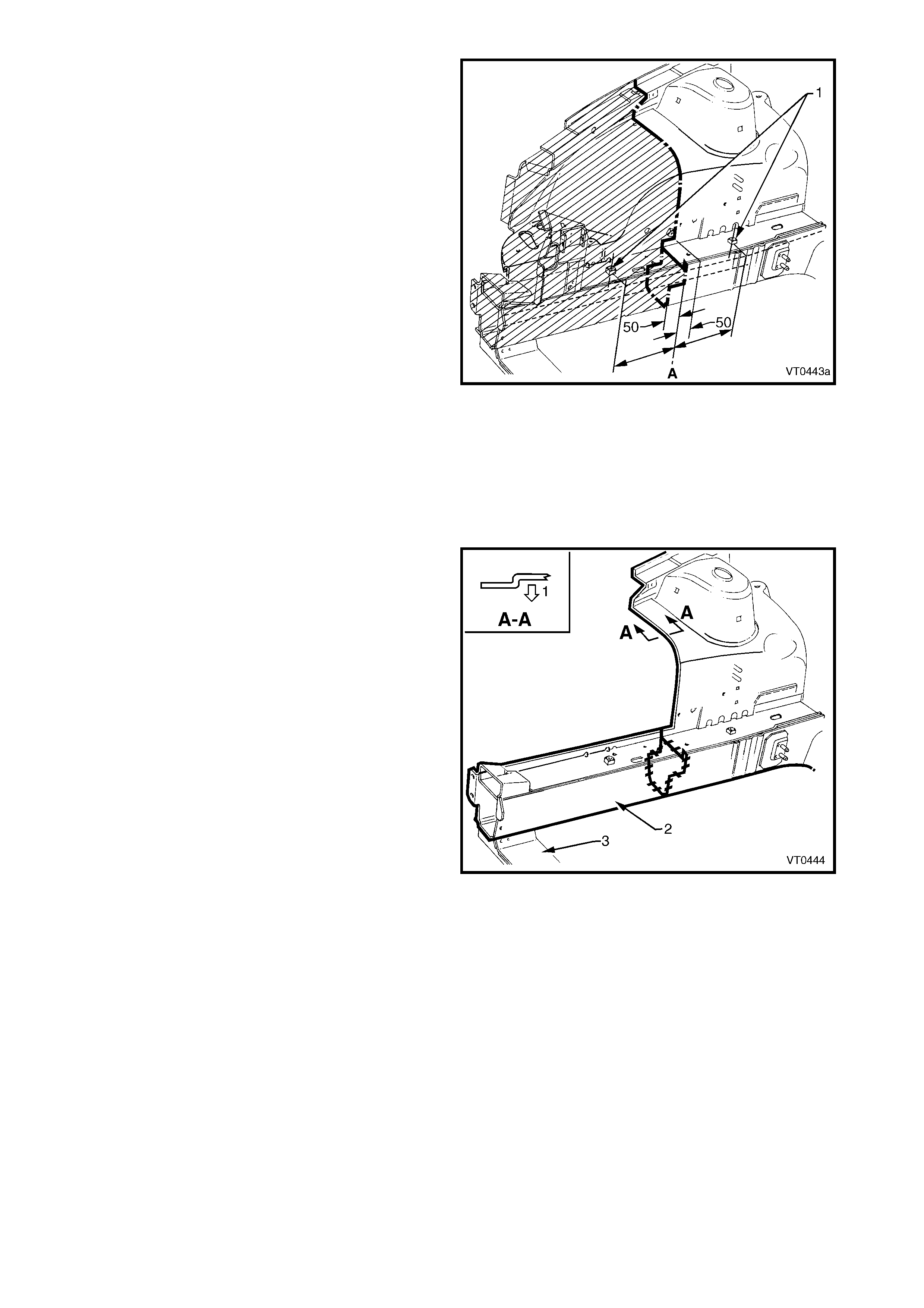
9. Cut the front side rail half way through its depth,
mid way between the two crossmember mounting
bolt holes shown A.
10. Step the cut forward by 50 mm as shown, so that
the load is not concentrated through a single line.
11. Ac c ur ately trim the f r ont wheelhouse panel, 50 mm
rearward of the top front side rail cut.
12. Repair any damage to adjacent areas.
13. Check and rectify the alignment of the body as
required, refer to 3. BODY DIMENSIONS in
Section 3A (Sedan), 3B (Wagon), 3C (Utility) or
3D (Coupe).
Figure 4-48
REPLACE
NOTE 1: Spot welding is the preferred method for attaching of panels and should be used whenever possible.
Where the spot welding equipment available will not access the required weld position, a plug weld should be
performed.
NOTE 2: The s ame number and pos ition of s pot welds (or plug welds) should be used when replac ing the panel,
as was used during manufacture, in order to maintain the original structural strength of the vehicle.
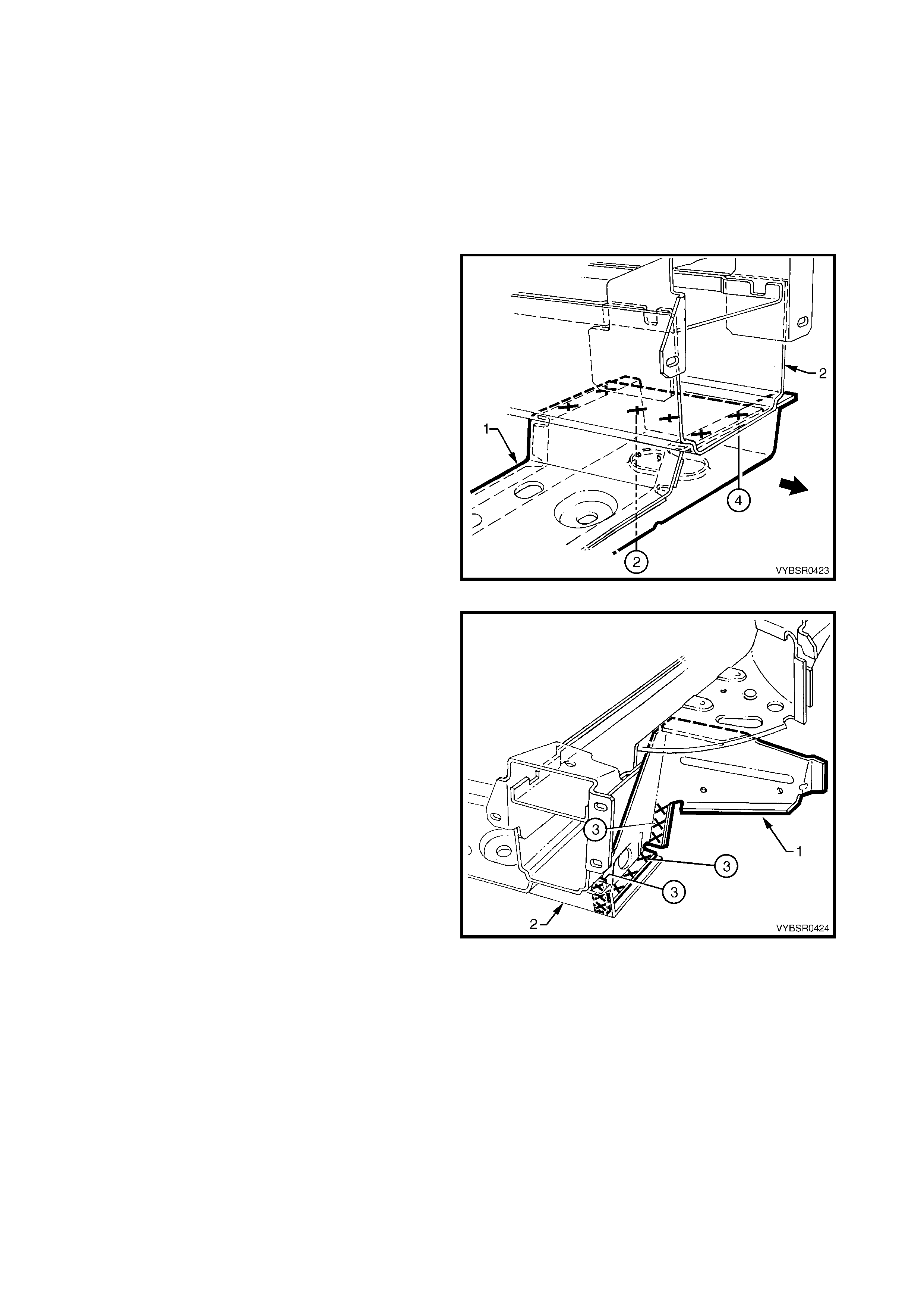
1. Using a suitable tool, modify the edge of the
rem aining section of the front wheelhouse panel to
form a joggle, to facilitate lap jointing. The joggle
should be towards the outside of the vehicle (1).
2. Accurately step cut the required section (2) from a
new front side rail assembly and clamp or tack
weld the new section in position.
3. Clamp the radiator lower support (3) in position.
Ensure the alignment of the front side rail
and lower support is correct, refer to
3. BODY DIMENSIONS in Section 3A (Sedan),
3B (Wagon), 3C (Utility) or 3D (Coupe).
4. Butt-weld the stepped longitudinal sections
together. The weld should extend around the
entire periphery of the cut.
5. Spot or plug weld the radiator lower support (3) in
place. Refer to 2.4 RADIATOR LOWER
SUPPORT ASSEMBLY – REPLACE.
Figure 4-49
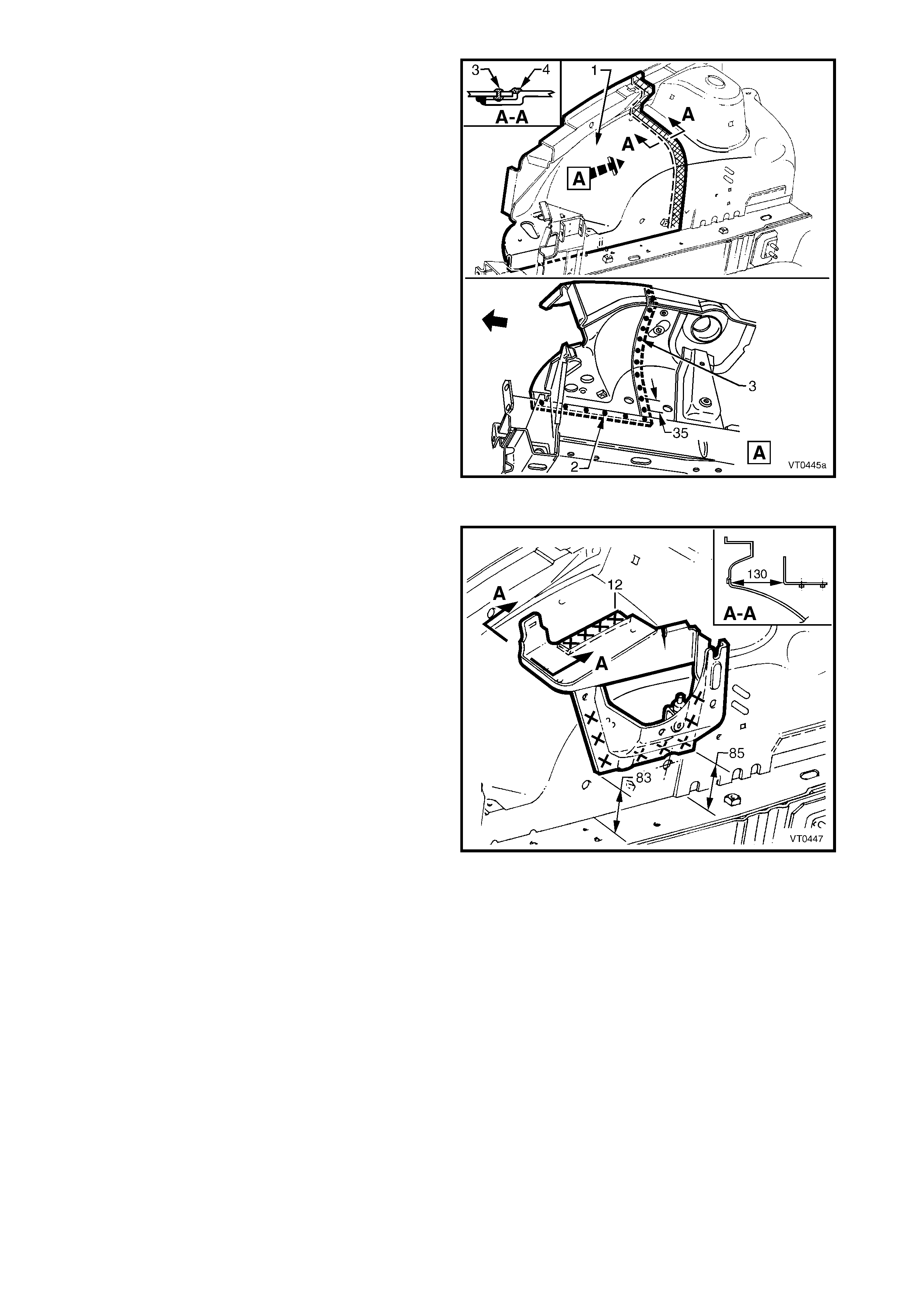
6. Accurately cut the required section (1) from a new
front wheelhouse panel assembly to replace the
removed section.
7. Drill the required holes in the lower edge of the
front wheelhouse panel to permit plug welding to
the front side rail.
8. Drill holes along the lap joint approximately every
25 mm, to accommodate plug welding of the joint.
9. Prepare all mating surfaces and treat with Weld
Through Primer (Item 1) as required, refer to
5. BODY SEALING, ADHESIVES & DEADENERS
in Section 3A (Sedan), 3B (Wagon), 3C (Utility)
or 3D (Coupe).
10. Clamp the modified front wheelhouse panel in
position and plug weld (2) to the front side rail.
11. Plug weld along the lap joint (3) through the
previously drilled holes.
12. Additionally, MIG (fillet) weld the front wheelhouse
panel sections together on the engine
compartment side (4).
13. Dress the welds on the engine compartment side
with a suitable grinder or sander, removing the
minimum amount of weld consis tent with achieving
an acceptable surface finish.
Figure 4-50
14. Reattach the ABS modulator bracket assembly, if
removed, in the position shown on the front
wheelhouse panel, by spot or plug welding.
15. Install the front wheelhouse panel upper side rail,
refer to 2.5 FRONT WHEELHOUSE PANEL
UPPER SIDE RAIL – REPLACE.
16. Install the front end panel assembly, refer to
2.1 FRONT END PANEL ASSEMBLY –
REPLACE.
Figure 4-51

17. Seal the wheel side of the seam with Joint Sealer
(Item 3) (1) and apply Spray-on Deadener (Item 7)
(2) to the wheel side of the f ront wheelhouse panel
assembly, refer to 5. BODY SEALING,
ADHESIVES & DEADENERS in Section
3A (Sedan), 3B (Wagon), 3C (Utility) or
3D (Coupe).
18. Refinish and paint panels and other components
as required. Refer to Section 3, 1.3 PAINT
REFINISHING.
19. Apply Joint Sealer (Item 3) as required. Refer to
5. BODY SEALING, ADHESIVES & DEADENERS
in Section 3A (Sedan), 3B (Wagon), 3C (Utility)
or 3D (Coupe).
20. Apply Cavity Wax ( Item 8) as requir ed to the inside
of any box sections or areas inaccessible to paint,
refer to 6. CAVITY WAX in Section 3A (Sedan),
3B (Wagon), 3C (Utility) or 3D (Coupe).
21. Install the fr ont bumper impact bar assemb ly, refer
to Section 3, 2. BUMPER IMPACT BAR
ASSEMBLIES.
22. Install the remaining components as described in
the appropriate Section of the MY 2003 VY & V2
Series II Service Information.
Figure 4-52
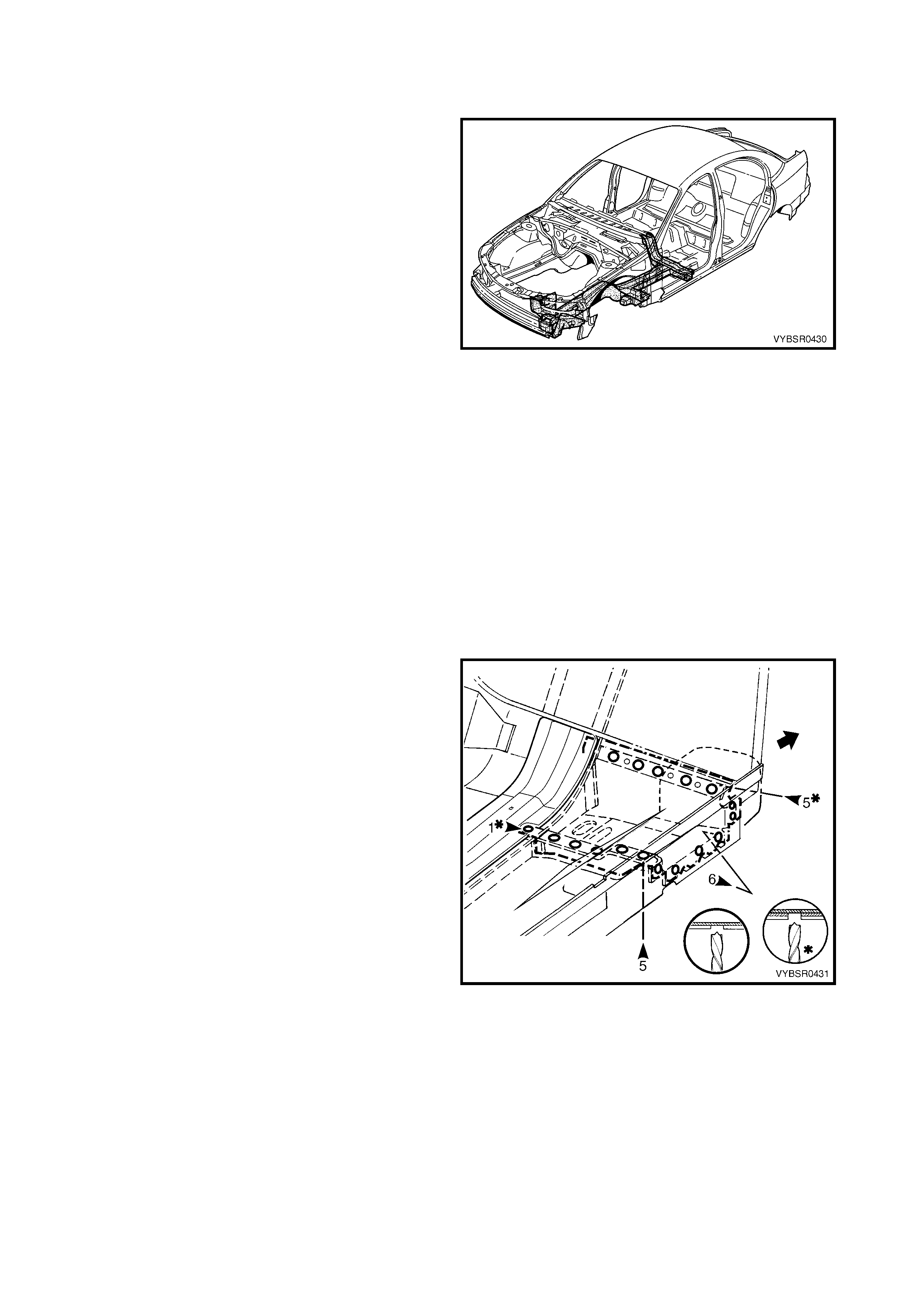
2.8 FRONT SIDE RAIL ASSEMBLY – REPLACE
REMOVE
IMPORTANT: The integrity of the front side rails is
critical to the function of the occupant protection
system. If the rails are incorrectly repaired following
damage, it is possible the seatbelt pretensioner and
airbag system will not function as intended, allowing
incorrect deployment. Refer to 1. GENERAL
DESCRIPTION for further information.
1. Remove the adjacent bolt-on panels and
components as described in the appropriate
Section of the MY 2003 VY & V2 Series II Service
Information.
2. Remove the front bumper impact bar assembly,
refer to Section 3, 2. BUMPER IMPACT BAR
ASSEMBLIES.
3. Secure the vehicle on a suitable fixture ensuring
that it is mounted without relying on support from
the front side rail assembly(s) being replaced.
Figure 4-53
4. Rem ove the f ront end panel ass em bly as required,
refer to 2.1 FRONT END PANEL ASSEMBLY.
5. Remove the radiator lower support assembly as
required, refer to 2.4 RADIATOR LOWER
SUPPORT ASSEMBLY – REPLACE.
6. Remove the front wheelhouse panel assembly as
required, refer to 2.6 FRONT WHEELHOUSE
PANEL ASSEMBLY – REPLA CE.
7. Using a scraper and heat gun, remove the body
sealer and deadener from the front floor and floor
extension in the front side rail attaching areas.
8. Spot cut the welds attaching the front floor panel
support ass embly to the front f loor panel and inner
rocker panel.
9. Spot cut the welds attaching the front side rail
assembly to the front floor extension panel and
front floor panel, refer to Figure 4-55.
Figure 4-54
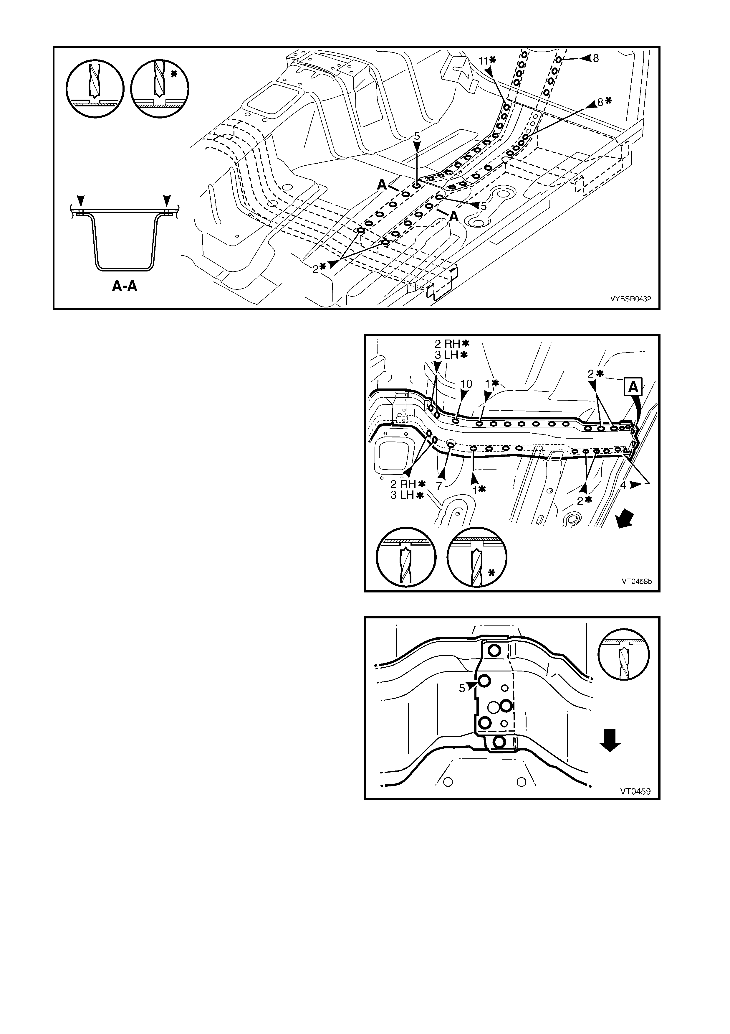
Figure 4-55
10. Spot cut four welds attaching the centre
crossmember to the inner rocker panel. Refer to
weld group A.
11. Spot cut the welds attaching the centre
crossmember to the front floor panel and seat
inner bracket assembly.
Figure 4-56
12. Spot cut five welds attaching the right-hand centre
crossmember to the left-hand centre
crossmember.
13. Remove the longitudinal assembly from the vehicle
and repair any damage to adjoining areas.
14. Check and rectify the alignment of the body as
required, refer to 3. BODY DIMENSIONS in
Section 3A (Sedan), 3B (Wagon), 3C (Utility) or
3D (Coupe).
Figure 4-57
REPLACE
NOTE 1: Spot welding is the preferred method for attaching of panels and should be used whenever possible.
Where the spot welding equipment available will not access the required weld position, a plug weld should be
performed.
NOTE 2: The s ame number and pos ition of s pot welds (or plug welds) should be used when replac ing the panel,
as was used during manufacture, in order to maintain the original structural strength of the vehicle.
1. Dress the floor in the areas where the front side rail assembly will attach and mark the new assembly with
drilling locations in preparation for plug welding. Drill holes as required.
2. Prepare all mating surfaces and treat with Weld Through Primer (Item 1) as required, refer to 5. BODY
SEALING, ADHESIVES & DEADENERS in Section 3A (Sedan), 3B (Wagon), 3C (Utility) or 3D (Coupe).
3. Secure the new front side rail assembly in position on the vehicle and clamp the radiator lower support
assembly in place.
4. Check the alignm ent of the front side r ail assem bly, ref er to 3. BODY DIMENSIONS in Section 3A (Sedan),
3B (Wagon), 3C (Utility) or 3D (Coupe).
5. Lightly tack weld the f ront side rail ass embly to the
floor in a few places, then recheck the alignment
as above. Correct as required.
Figure 4-58
6. Plug weld the front side rail assembly to the front
floor panel extension and front floor panel.
Figure 4-59
7. Plug weld the centre crossmember to the inner
rock er panel, ref er to weld group A and to the front
floor panel.
Figure 4-60
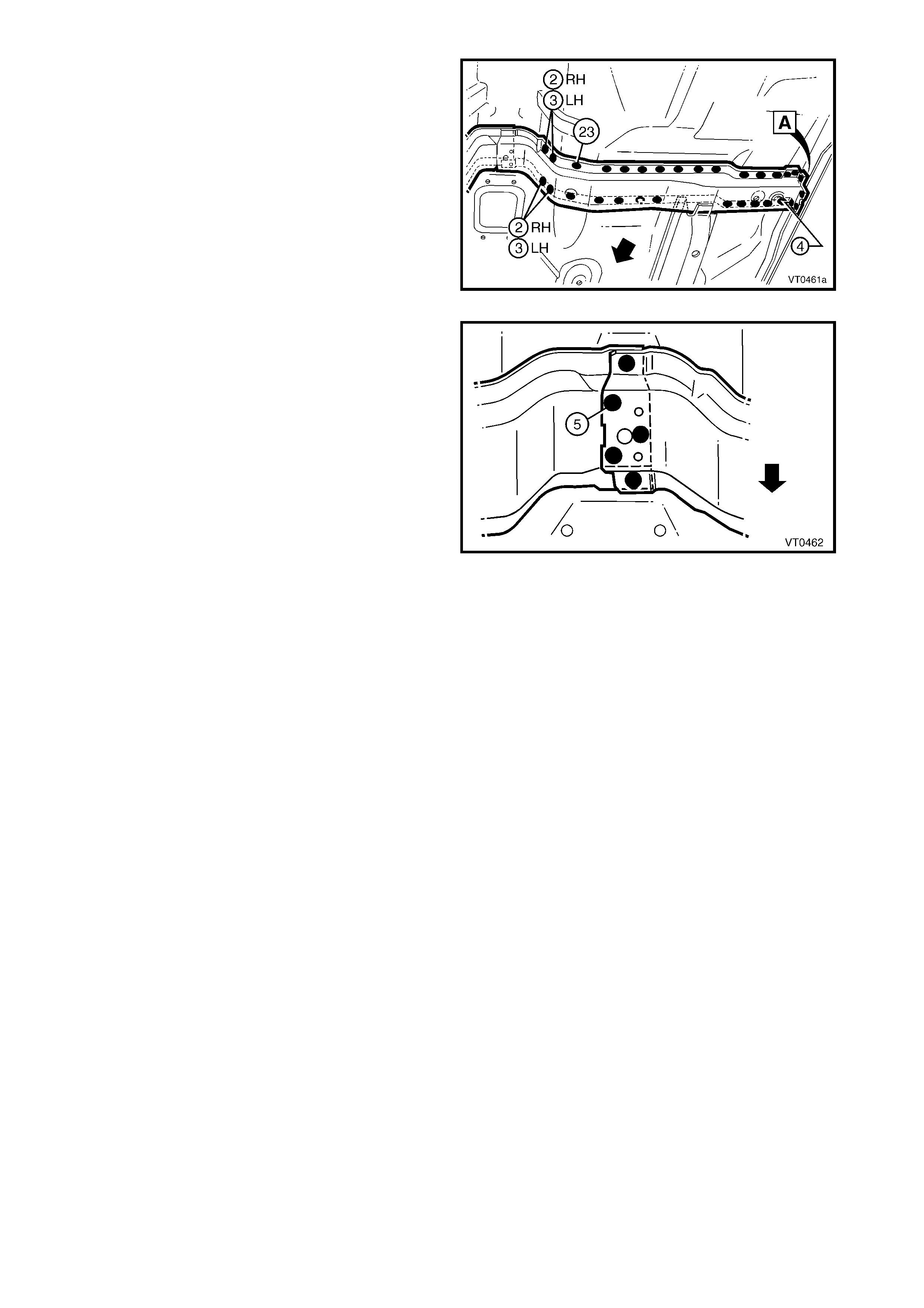
8. Plug weld in four places, the right-hand centre
crossmember to the left-hand centre
crossmember.
Figure 4-61
9. Plug or spot weld the front floor panel support
assembly to the front floor panel and inner rocker
panel.
10. Reinstall the radiator lower support assembly, refer
to 2.4 RADIATOR LOWER SUPPORT
ASSEMBLY – REPLACE.
11. Install the front wheelhouse panel assembly, refer
to 2.6 FRONT WHEELHOUSE PANEL
ASSEMBLY – REPLACE.
12. Install the front end panel assembly, refer to
2.1 FRONT END PANEL ASSEMBLY –
REPLACE.
13. Refinish and paint panels and other components
as required. Refer to Section 3, 1.3 PAINT
REFINISHING.
14. Apply Joint Sealer (Item 3) as required. Refer to
5. BODY SEALING, ADHESIVES & DEADENERS
in Section 3A (Sedan), 3B (Wagon), 3C (Utility)
or 3D (Coupe).
15. Apply Cavity Wax ( Item 8) as requir ed to the inside
of any box sections or areas inaccessible to paint,
refer to 6. CAVITY WAX in Section 3A (Sedan),
3B (Wagon), 3C (Utility) or 3D (Coupe).
16. Apply Spray-on Deadener (Item 7), after the
application of body colour. Refer to 5. BODY
SEALING, ADHESIVES & DEADENERS in
Section 3A (Sedan), 3B (Wagon), 3C (Utility) or
3D (Coupe).
17. Install the fr ont bumper impact bar assemb ly, refer
to Section 3, 2. BUMPER IMPACT BAR
ASSEMBLIES.
18. Install the remaining components as described in
the appropriate Section of the MY 2003 VY & V2
Series II Service Information.
Figure 4-62