
SECTION 7A - BODY SIDE – SEDAN
IMPORTANT
Before perfo rming any Service O perat ion or o th er pro cedu re describ ed in th is Section, refer to Section
00 CAUTIONS AND NOTES and Section 2 PRECAUTIONS in this Supplement for correct workshop
practices with regard to safety and/or property damage.
CAUTION
The Structure of the M Y 2003 VY & V2 Series II body shell has been developed using complex design
and development techniques. In addition to meeting all required standards, the v ehicle body is also a
critical part of the overall safety systems. It is therefore imperative the repair procedures described
here are adhered to during all vehicle body repairs.
CONTENTS
1. GENERAL DESCRIPTION
1.1 BODY SIDE COMPONENTS
2. SERVICE OPERATIONS
2.1 REAR QUARTER PANEL – REPLACE
REMOVE
REPLACE
2.2 TAIL LAMP HOUSING, QUARTER PANEL
LOWER EXTENSION & QUARTER PANEL
UPPER EXTENSION – REPLACE
REMOVE
REPLACE
2.3 TAIL LAMP HOUSING BRACE – REPLACE
REMOVE
REPLACE
2.4 DOOR OPENING FRAME ASSEMBLY – REPLACE
REMOVE
REPLACE
2.5 DOOR OPENING FRAM E ASSEMBLY – PARTIAL
REPLACE, HINGE PILLAR
REMOVE
REPLACE
2.6 DOOR OPENING FRAM E ASSEMBLY – PARTIAL
REPLACE, CENTRE PILLAR
REMOVE
REPLACE
2.7 DOOR OPENING FRAM E ASSEMBLY – PARTIAL
REPLACE, LOCK PILLAR
REMOVE
REPLACE
2.8 DOOR OPENING FRAM E ASSEMBLY – PARTIAL
REPLACE, ROCKER PANEL
REMOVE
REPLACE
2.9 FENDER LOWER REAR BRACKET –
REPLACE
2.10 HINGE PILLAR INNER PANEL ASSEMBLY –
REPLACE
REMOVE
REPLACE
2.11 QUARTER PANEL INNER ASSEMBLY –
REPLACE
REMOVE
REPLACE
2.12 QUARTER PANEL INNER ASSEMBLY –
PARTIAL REPLACE
REMOVE
REPLACE
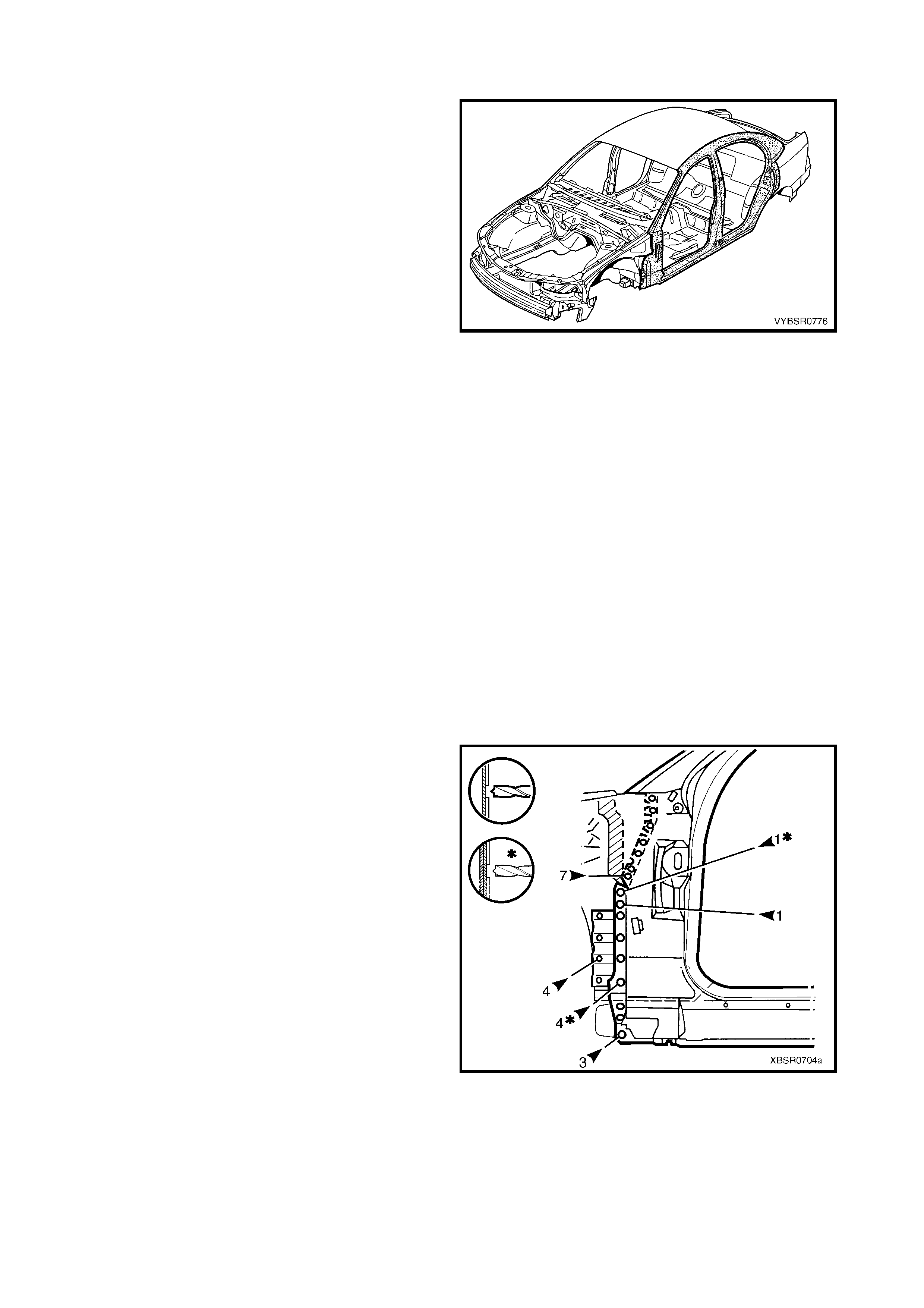
1. GENERAL DESCRIPTION
This Section des c ribes the r eplacement pr ocedur es f or the body side com ponents of the MY 2003 VY Series Sedan
body structure. Removal of bolt-on panels and mechanical components is not covered.
When repairing the body side of the vehicle, care must be taken to ensure the structure is returned to its original
production configuration. This is especially important to maintain side impact standards and for the vehicle’s
occupant protection system to operate correctly.
This Section includes door opening frame assembly partial replacement procedures for the hinge pillar, centre pillar,
lock pillar and rocker panel. These procedures must be followed carefully, as they regularly involve hidden
reinforcement panels. The cutting locations specified are the only places allowable.
IMPORTANT: A sunroof option is available that is fitted on the production line. To cater for this option, a stainless
steel front drain tube is also fitted within the hinge pillar cavity, therefore the partial replacement procedure for the
hinge pillar must not be performed on these vehicles.
NOTE: It is imperative that the correct body adhesives, sealers, deadeners and cavity waxes are used when
repairing the body structure of MY 2003 VY Sedan vehicles. Refer to 5. BODY SEALING, ADHESIVES &
DEADENERS and 6. CAVITY WA X in Section 3A for details of the correct materials and their commercially
available equivalents.
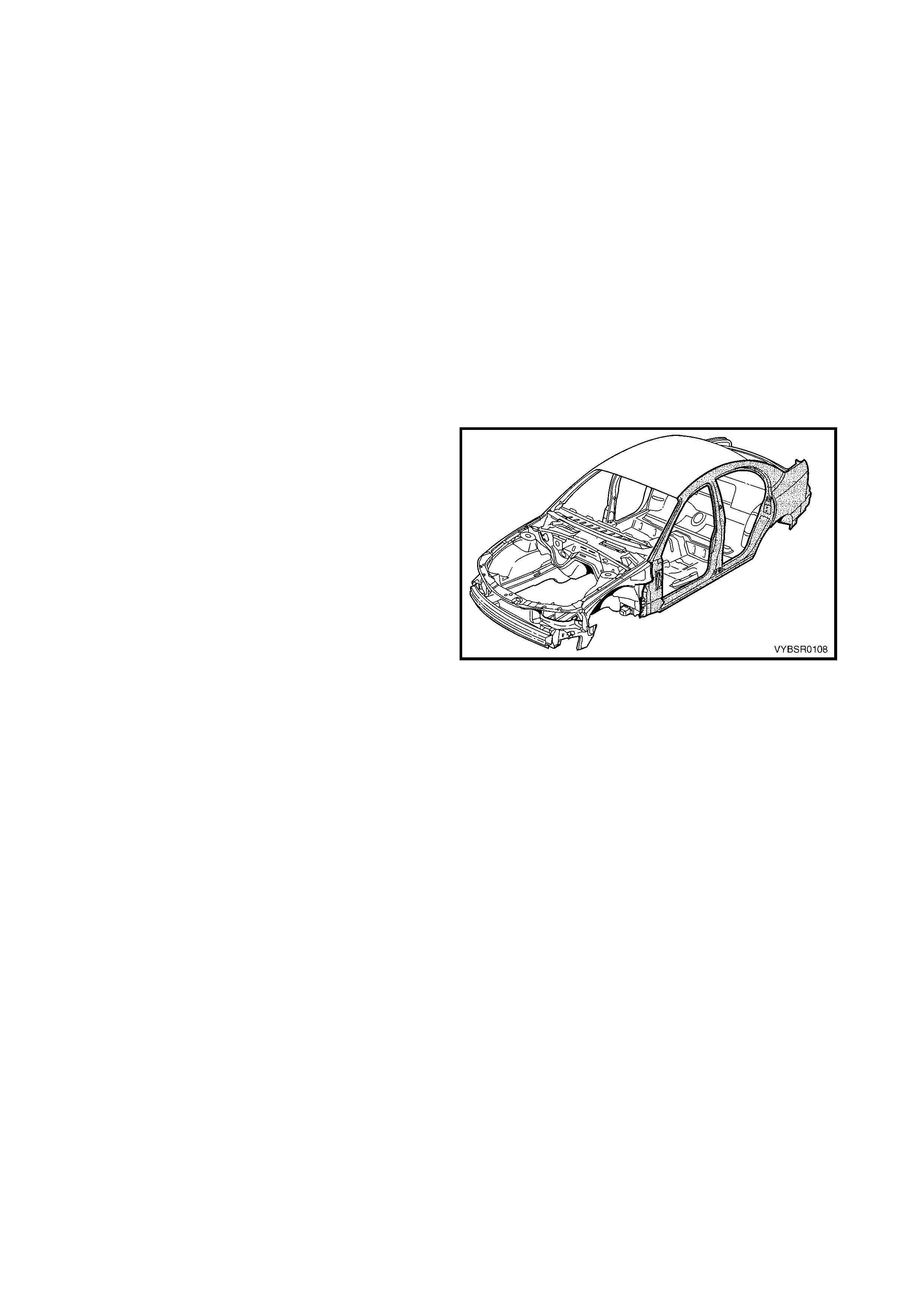
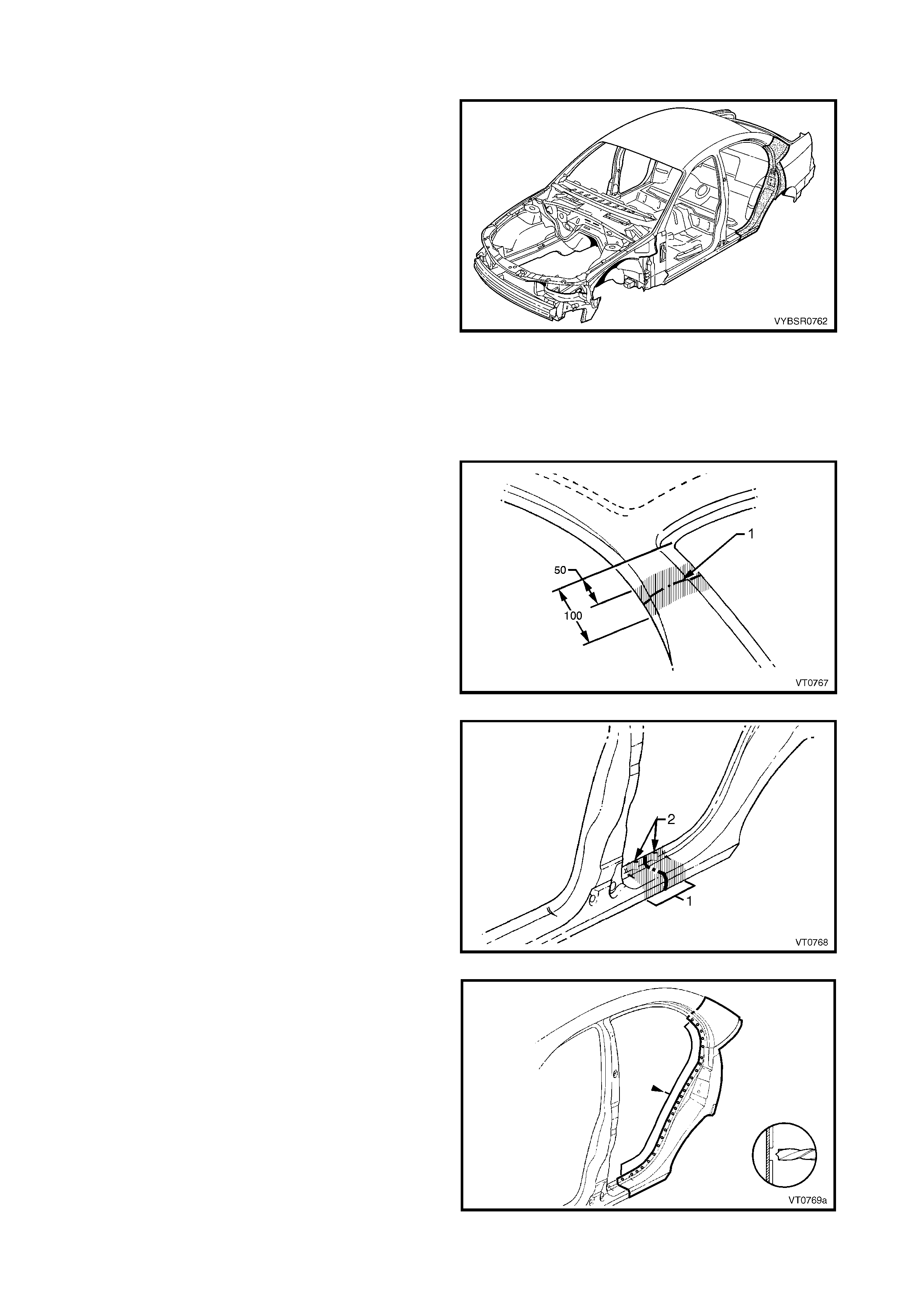
1.1 BODY SIDE COMPONENTS
The shaded components in Figure 7A-1 are those
dealt with in this Section.
The components and assemblies shown in Figure 7A-
2 are the parts s erviced for MY 2003 VY Series Sedan
vehicles which form the basis of the repair procedures
in this Section. For a detailed view of the body
components, refer to Section 3A BODY
CONSTRUCTION – SEDAN.
NOTE: Always refer to your Authorised Retailer for
spare parts availability configurations.
IMPORTANT: Cavity foam may be used within the
hinge, centre and lock pillars. Care needs to be taken
when repairing the vehicle in these areas, refer to
Section 2, 10. CAVITY FOAM prior to beginning any
work for further information.
Figure 7A-1
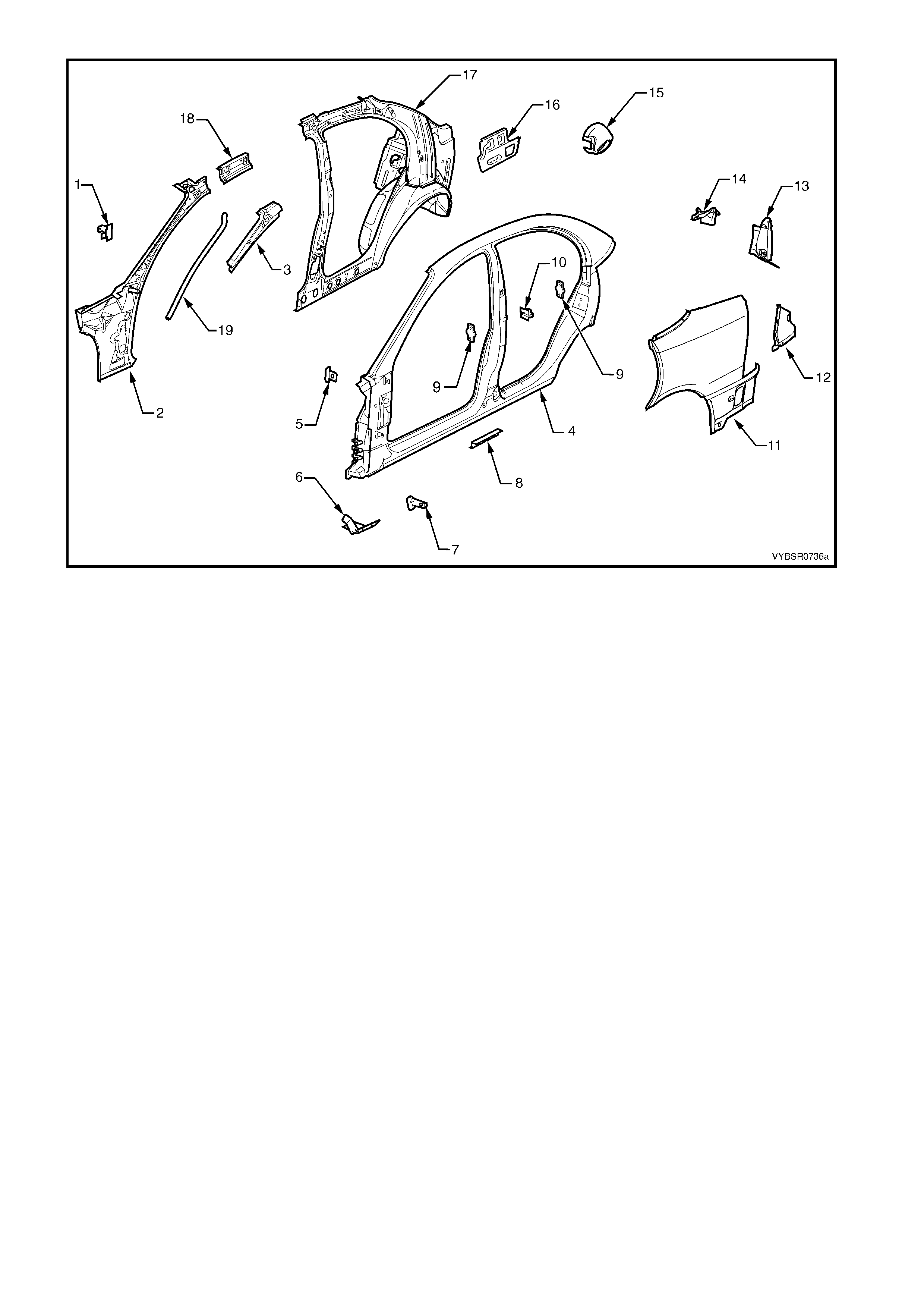
Figure 7A-2
Legend
1. Hinge Pillar Trim Panel Bracket
2. Hinge Pillar Inner Panel Assembly
3. Hinge Pillar Upper Reinforcement
4. Door Opening Frame Assembly
5. Fender Upper Rear Bracket
6. Fender Lower Rear Bracket
7. Fender Rear Bracket
8. Underbody Jacking Locator
9. Front or Rear Door Striker Anchor Plate
10. Rear Door Check Link Bracket
10. Rear Quarter Panel
11. Quarter Panel Lower Extension
12. Tail Lamp Housing
13. Quarter Panel Upper Extension
14. Fuel Filler Pipe Housing
15. Tail Lamp Housing Brace
16. Quarter Panel Inner Assembly
17. Quarter Panel Inner Extension
18. Sunroof Front Drain Tube
NOTE 1: Door opening frame assembly includes parts 3, 5, 6, 7, 8, 9, 10 19.
NOTE 2: Quarter panel inner assembly includes parts 18 and the rear wheelhouse inner panel assembly which
is also available separately, refer to Section 10A BODY REAR – SEDAN.
2. SERVICE OPERATIONS
2.1 REAR QUARTER PANEL – REPLACE
NOTE: The rear quarter panel is not available as an
assembly with the tail lamp housing, quarter panel
upper extension, quarter panel lower extension or fuel
filler pipe housing (for right-hand side).
This procedure details the removal of the rear quarter
panel as an assembly with the above parts.
Replacement of the smaller panels is described in this
and the subsequent procedure.
REMOVE
CAUTION: To avoid the possibility of fire, take
particular care when cutting or welding at the rear
of the vehicle. Remove the fuel tank and plug all
fuel lines.
1. Remove the adjacent bolt-on panels and
components as described in the appropriate
Section of the MY 2003 VY & V2 Series II Service
Information.
2. Remove the rear window, refer to Section 1A6
STATIONARY WINDOWS in the MY 2003 VY &
V2 Series II Service Information.
3. Remove the rear bumper impact bar, refer to
Section 3, 2. BUMPER IMPACT BAR
ASSEMBLIES.
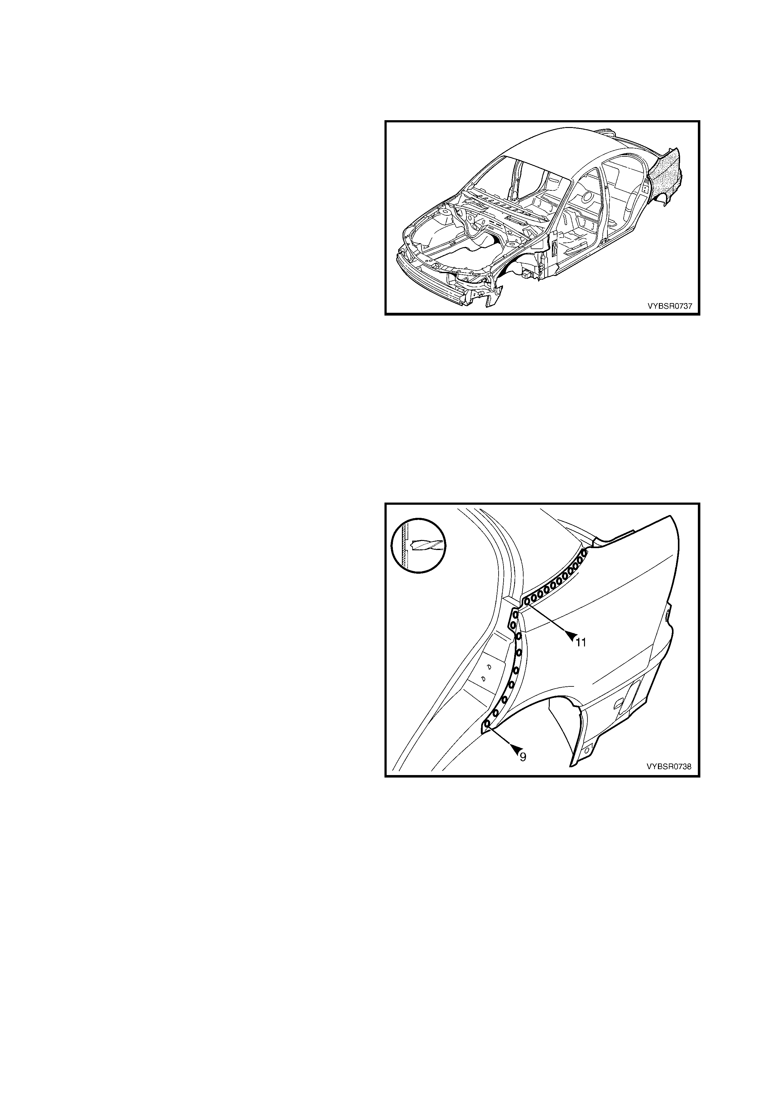
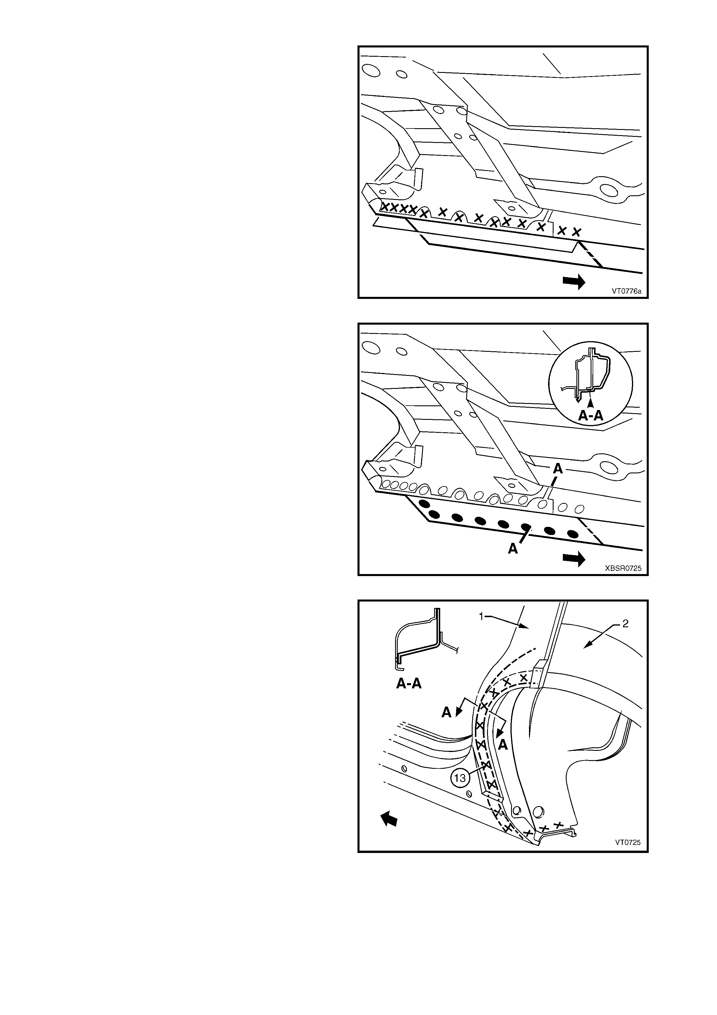
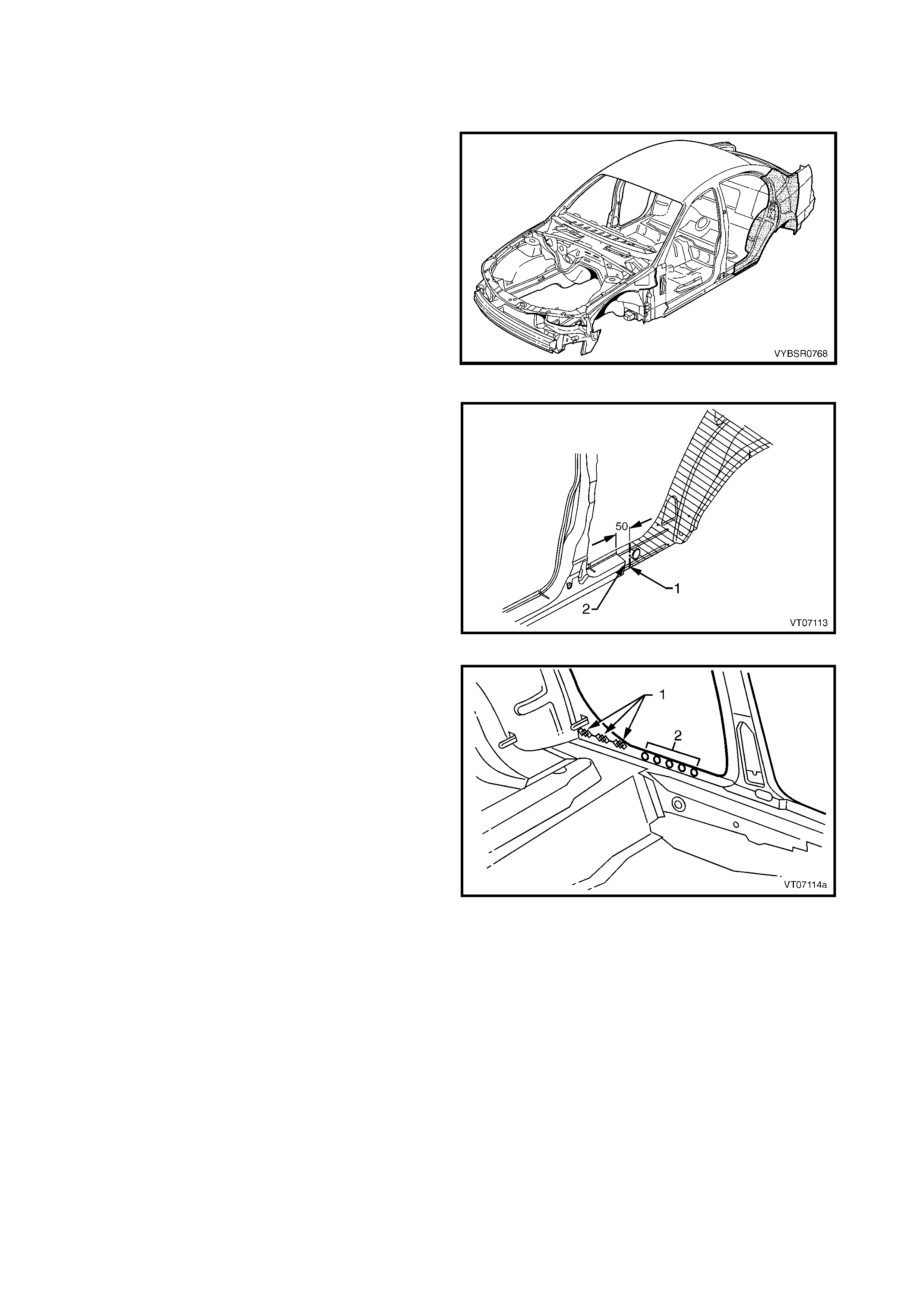
Figure 7A-3
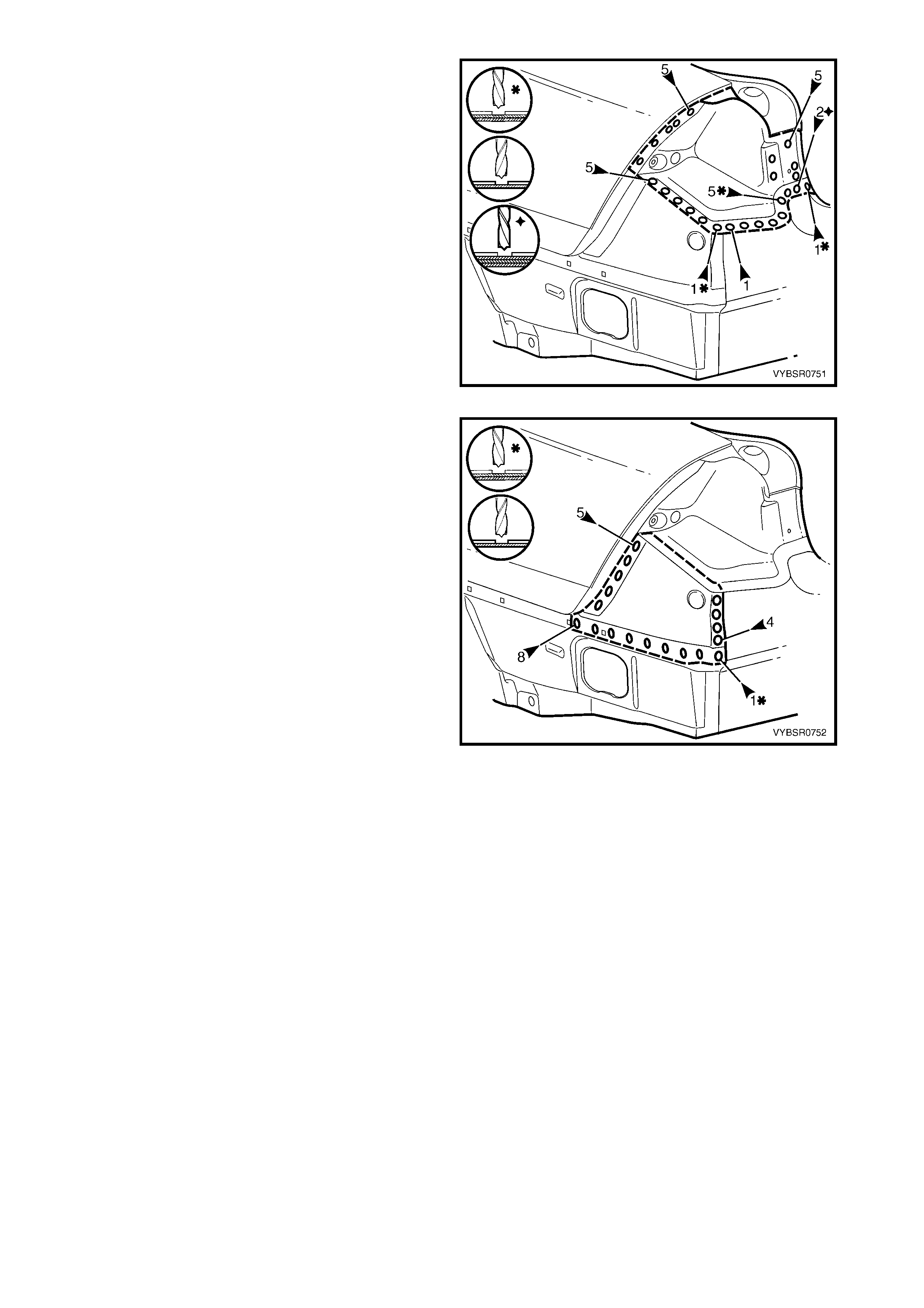
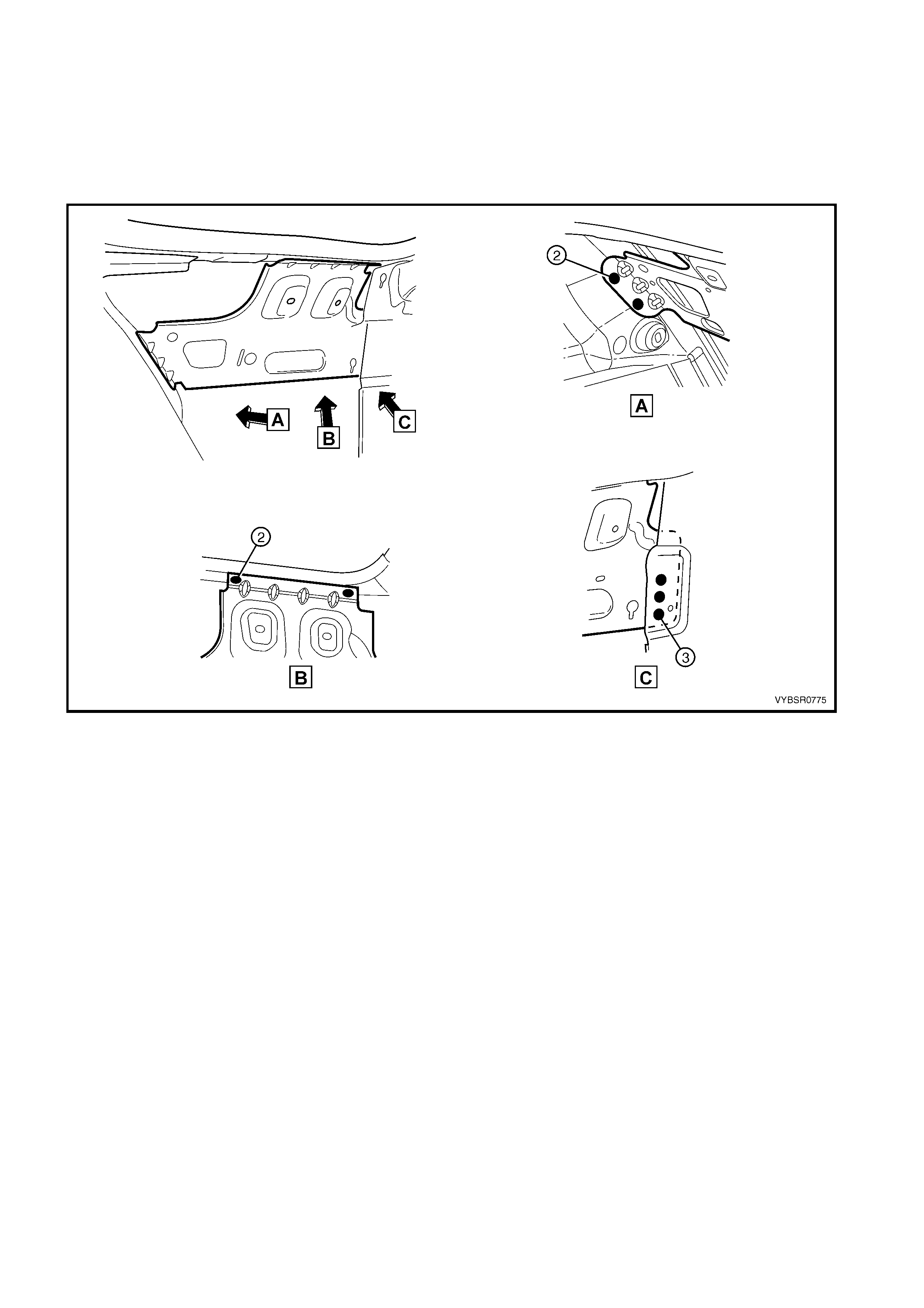
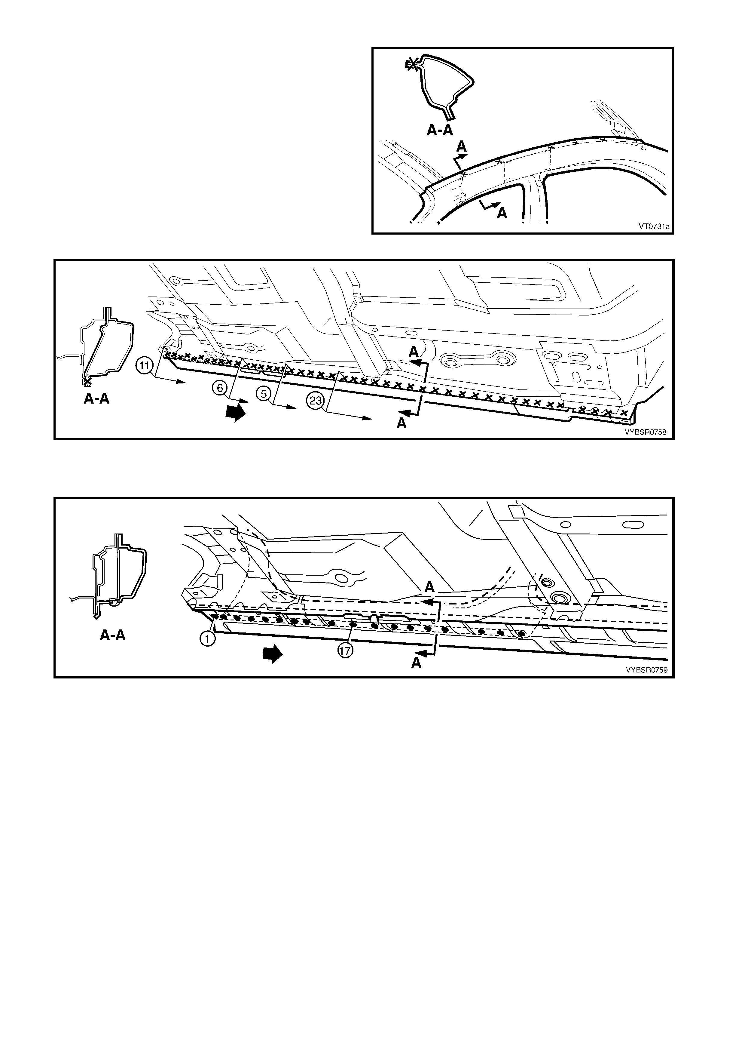
4. Spot cut the welds attaching the rear quarter panel
to the door opening frame assembly.
5. Spot cut the welds attaching the rear quarter panel
to the quarter panel inner assembly and rear
compartment floor panel outer extension. There
are a different number of welds on the left-hand
panel (1) to the right-hand panel (2), refer to Figure
7A-5.
Figure 7A-4
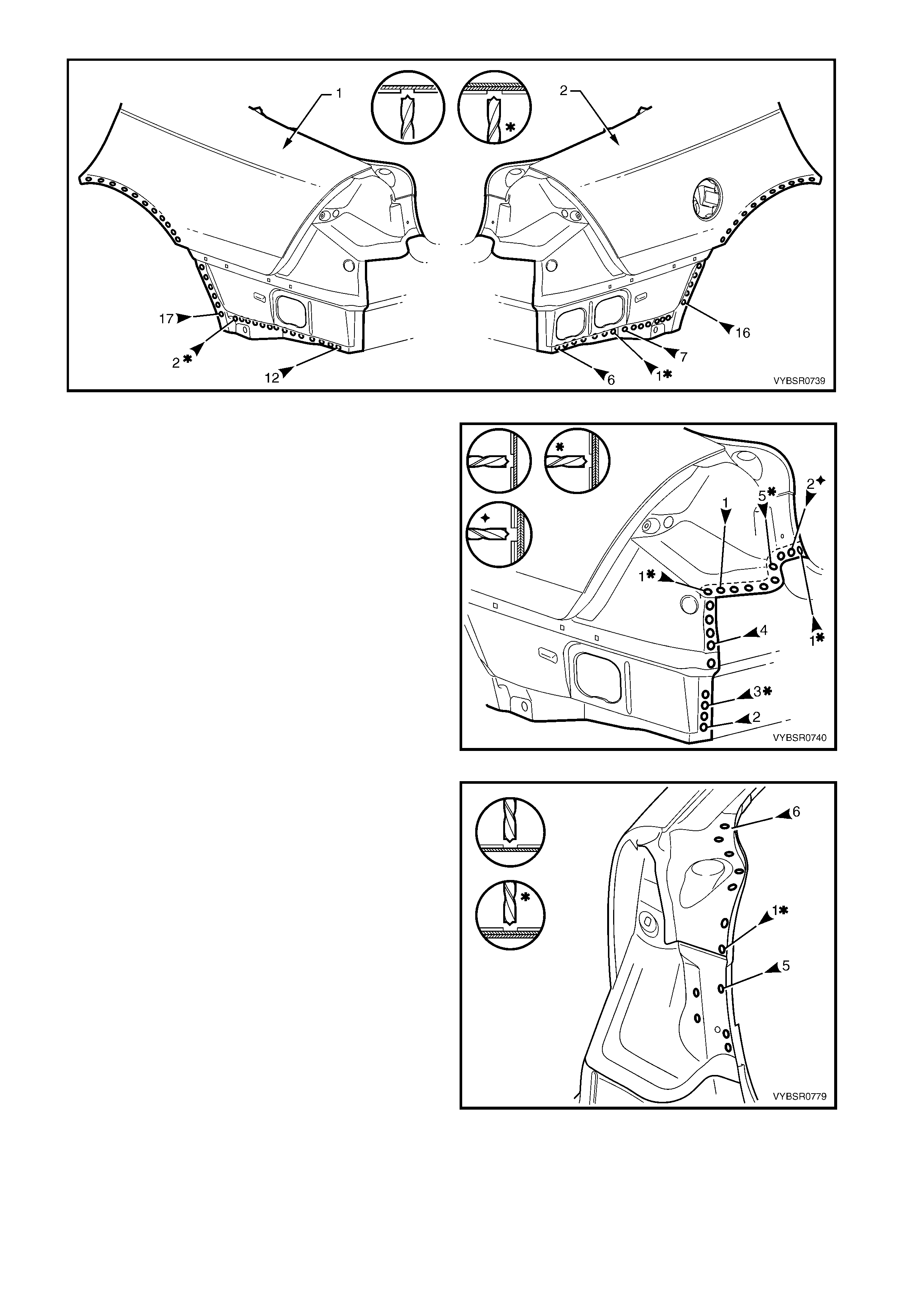
Figure 7A-5
6. Spot cut the rear quarter panel from the rear end
lower panel and web plate.
7. Spot cut the tail lamp housing and quarter panel
lower extension panel from the rear end lower
panel.
NOTE: If the tail lam p hous ing and quarter panel lower
extension are to remain, modify this procedure
accordingly .
Figure 7A-6
8. Spot cut the rear quarter panel upper extension
and tail lamp housing from the rear end lower
panel extension.
NOTE: If the tail lam p hous ing and quarter panel lower
extension are to remain, this step is not required.
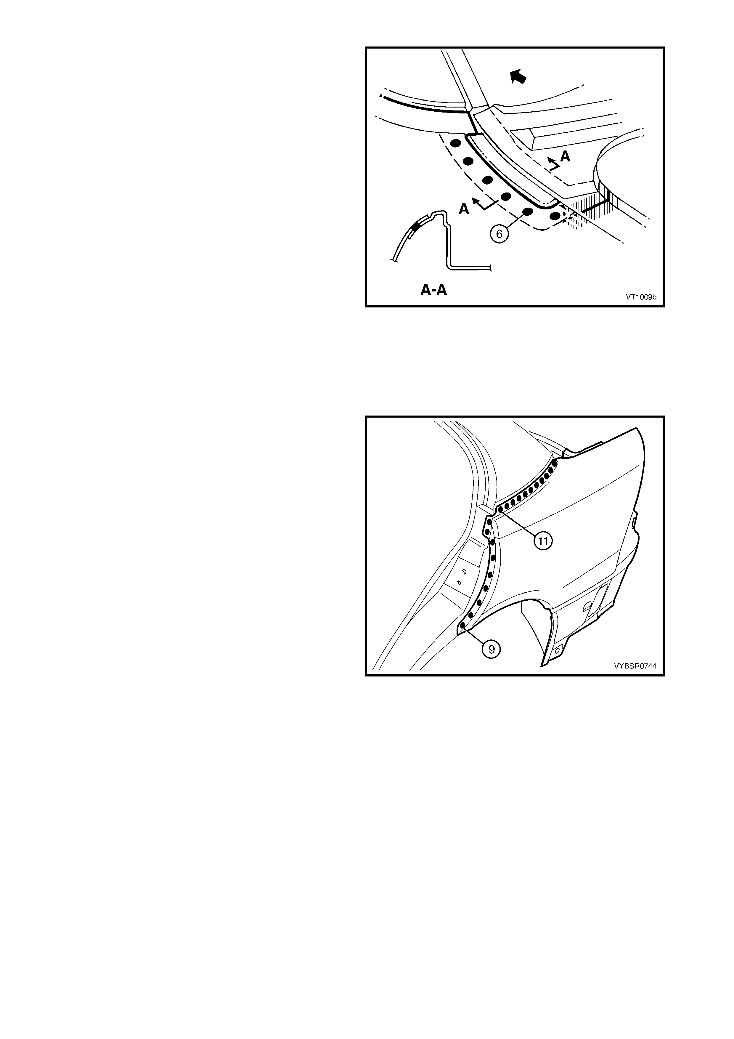
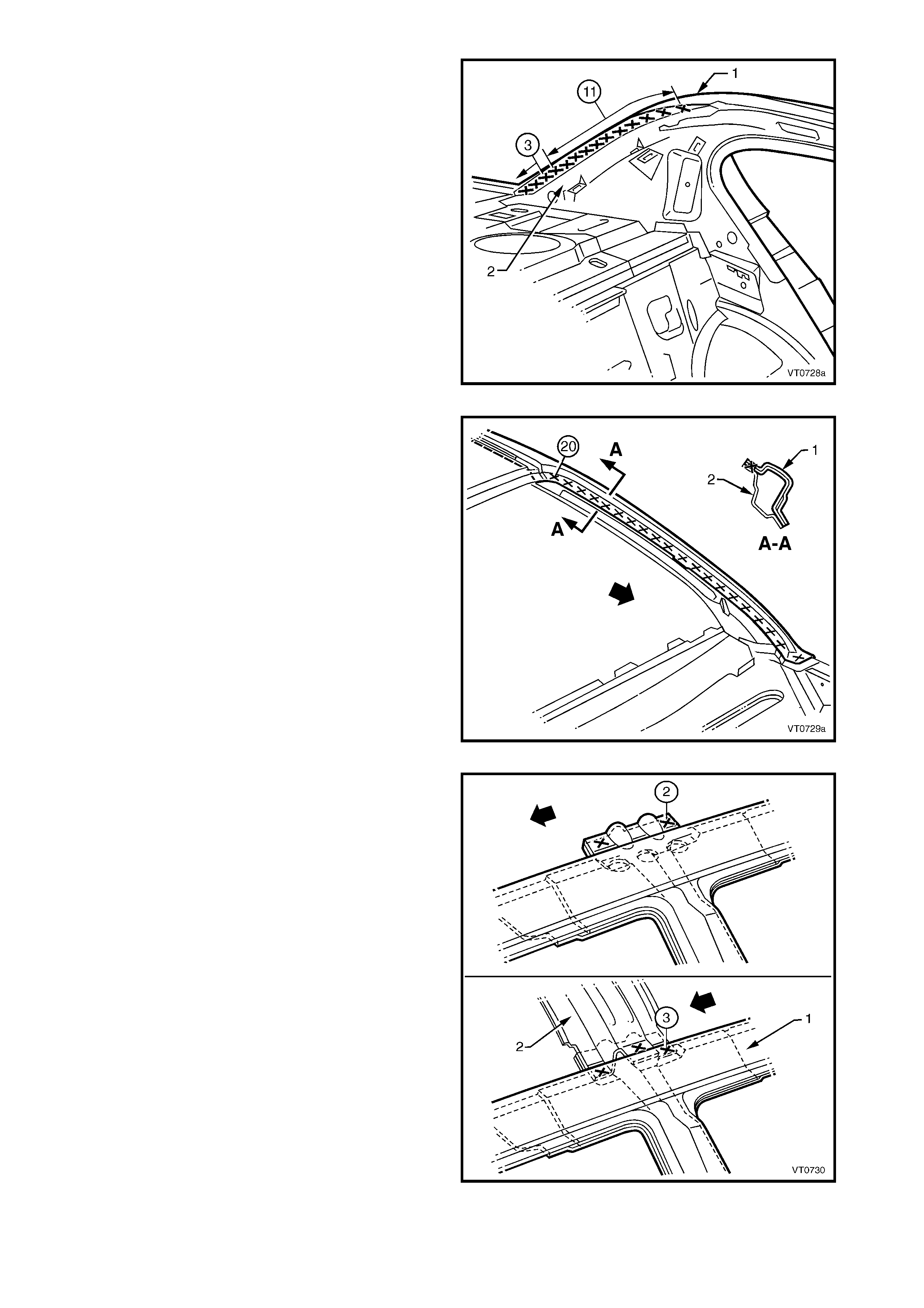
9. Spot cut the tail lamp housing brace from the tail
lamp housing (A) and rear quarter panel (B), refer
to Figure 7A-8.
Figure 7A-7
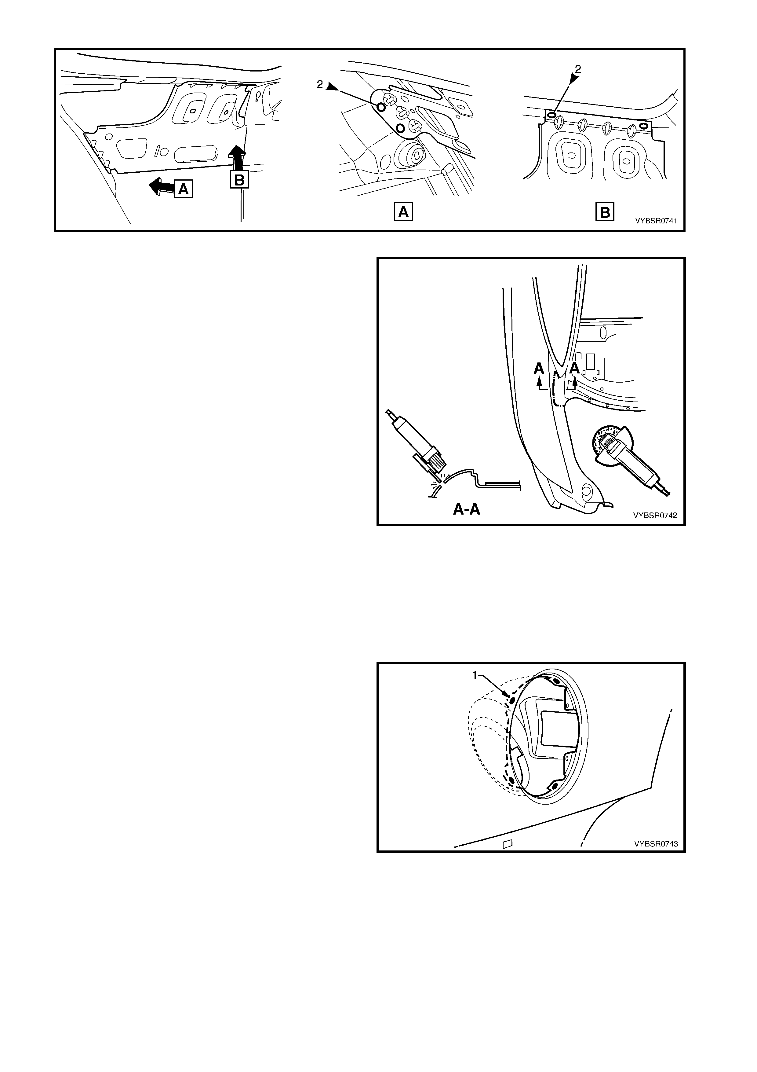
Figure 7A-8
NOTE: At the point at the base of the lock pillar, the
rear quarter panel is sandwiched between the quarter
inner panel assembly and rear window panel
assem bly. Cutting the panel at this point, as described
below, rather than removing extra panels, will save
considerable time and effort as structural adhesive is
used in this area.
10. Using a saw or other appropriate equipment, cut
through the rear quarter panel 40 - 50 mm from
the top edge. The c ut should pas s acr os s the dr ain
channel, then along the visible face of the quarter
panel as illustrated, until the panel is detached
from the vehicle.
NOTE: It is important to leave enough material to
facilitate a lap joint of the old and new panels.
11. Remove the panel from the vehicle, and then
repair any damage to adjacent parts.
12. Check and rectify the alignment of the body as
required, refer to 3. BODY DIMENSIONS in
Section 3A.
Figure 7A-9
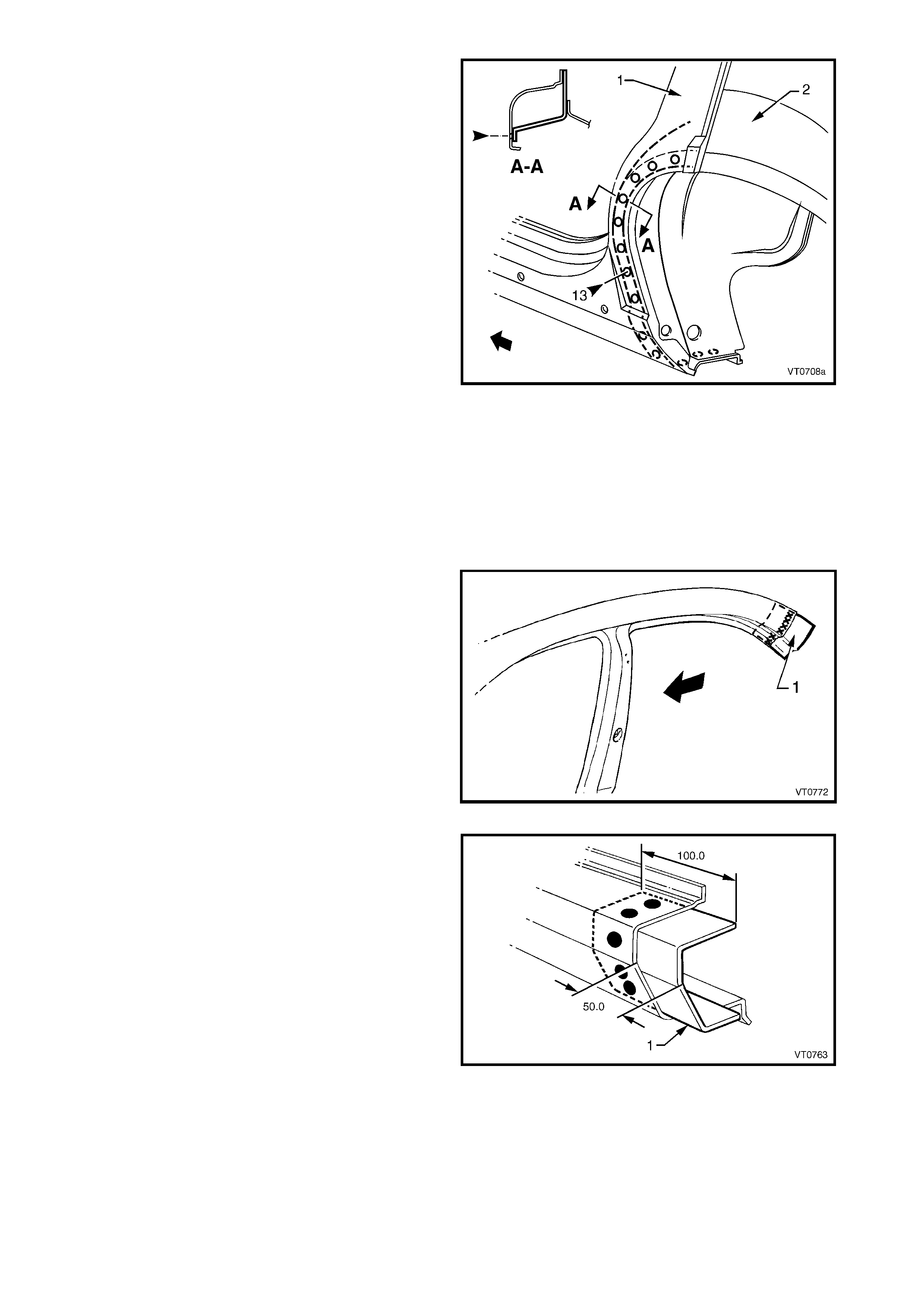
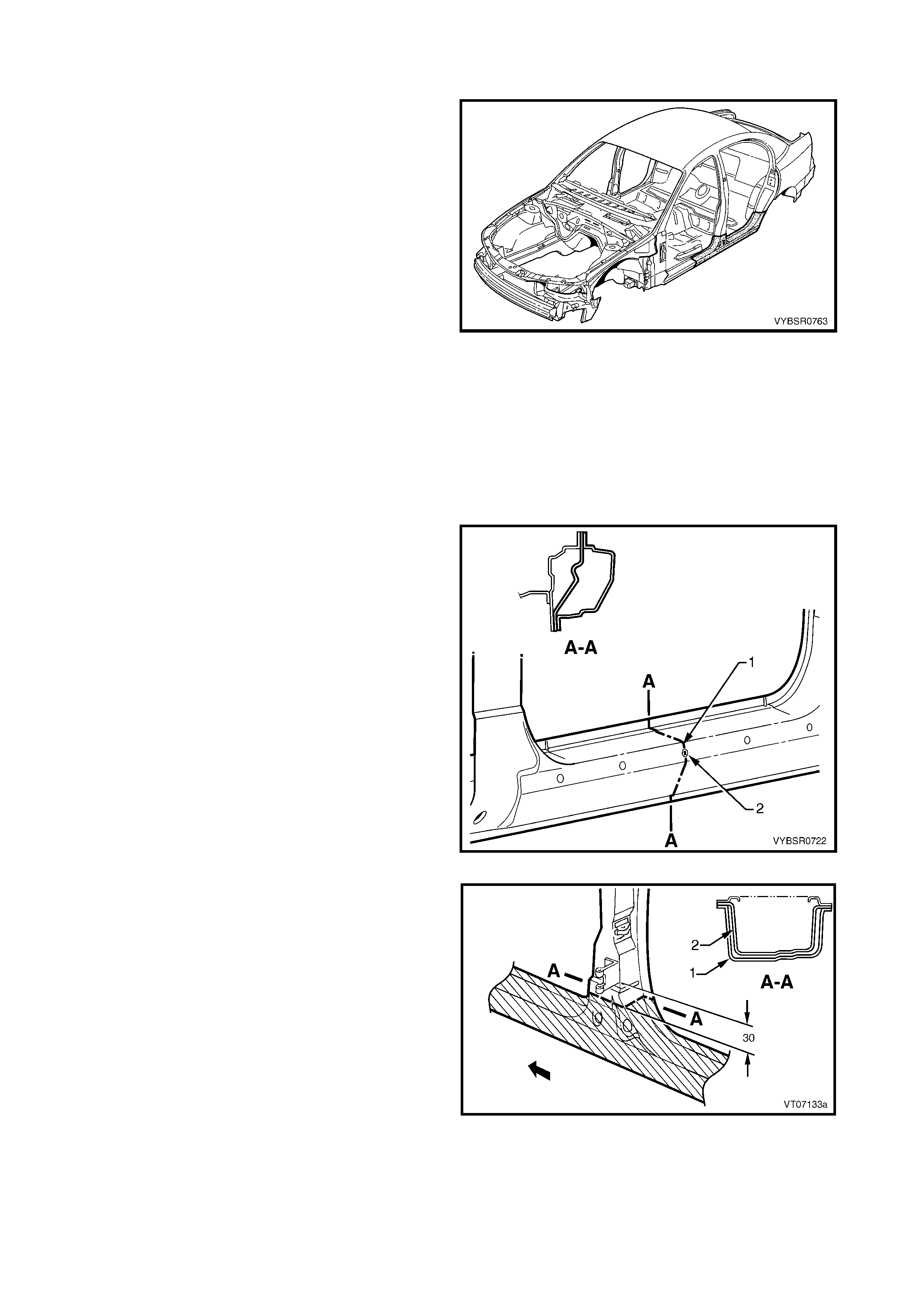
REPLACE
NOTE 1: Spot welding is the preferred method for attaching of panels and should be used whenever possible.
Where the spot welding equipment will not access the required weld position, a plug weld should be performed.
NOTE 2: The s ame number and pos ition of s pot welds (or plug welds) s hould be used when r eplacing the panel,
as was used during manufacture, in order to maintain the original structural strength of the vehicle.
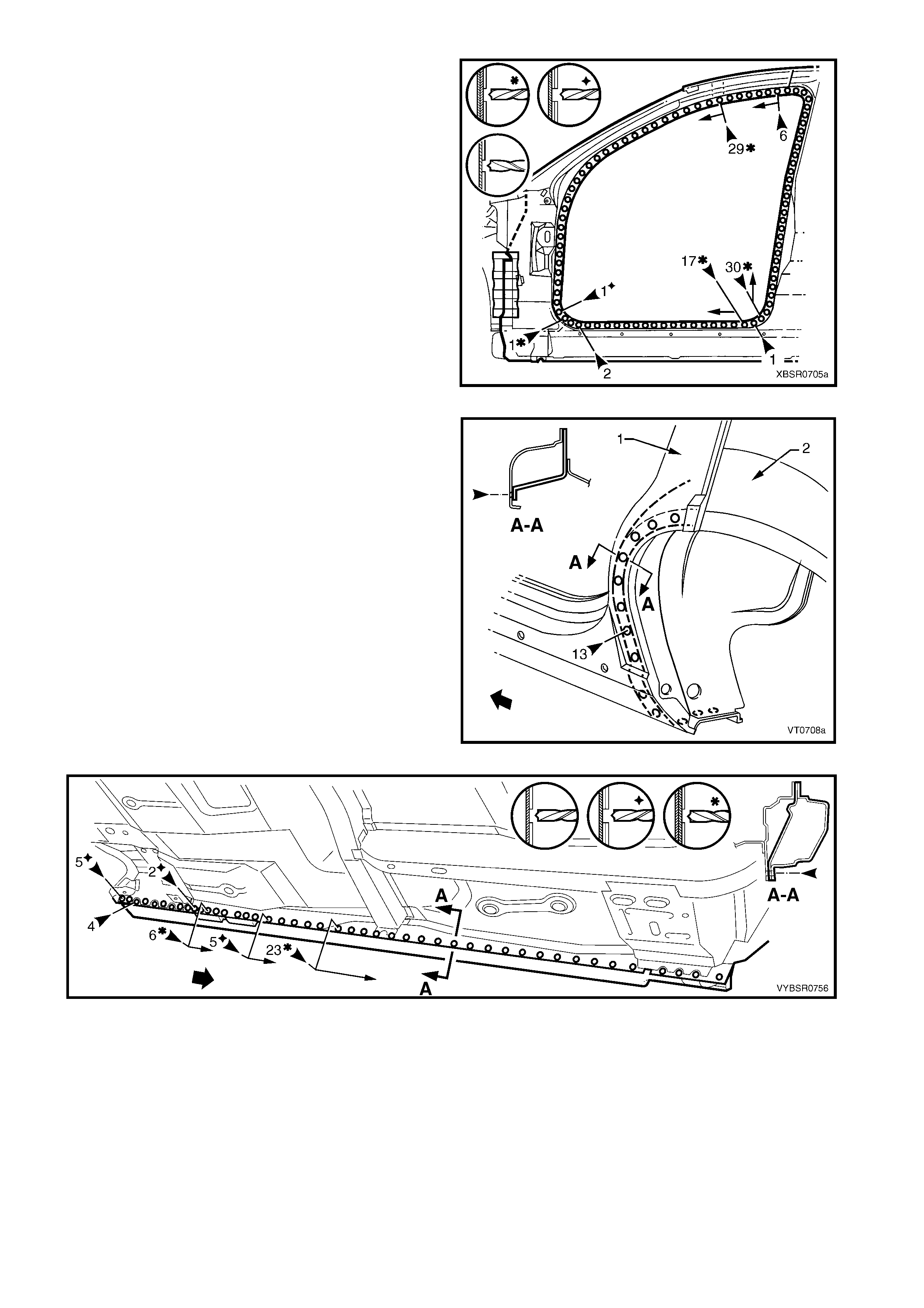
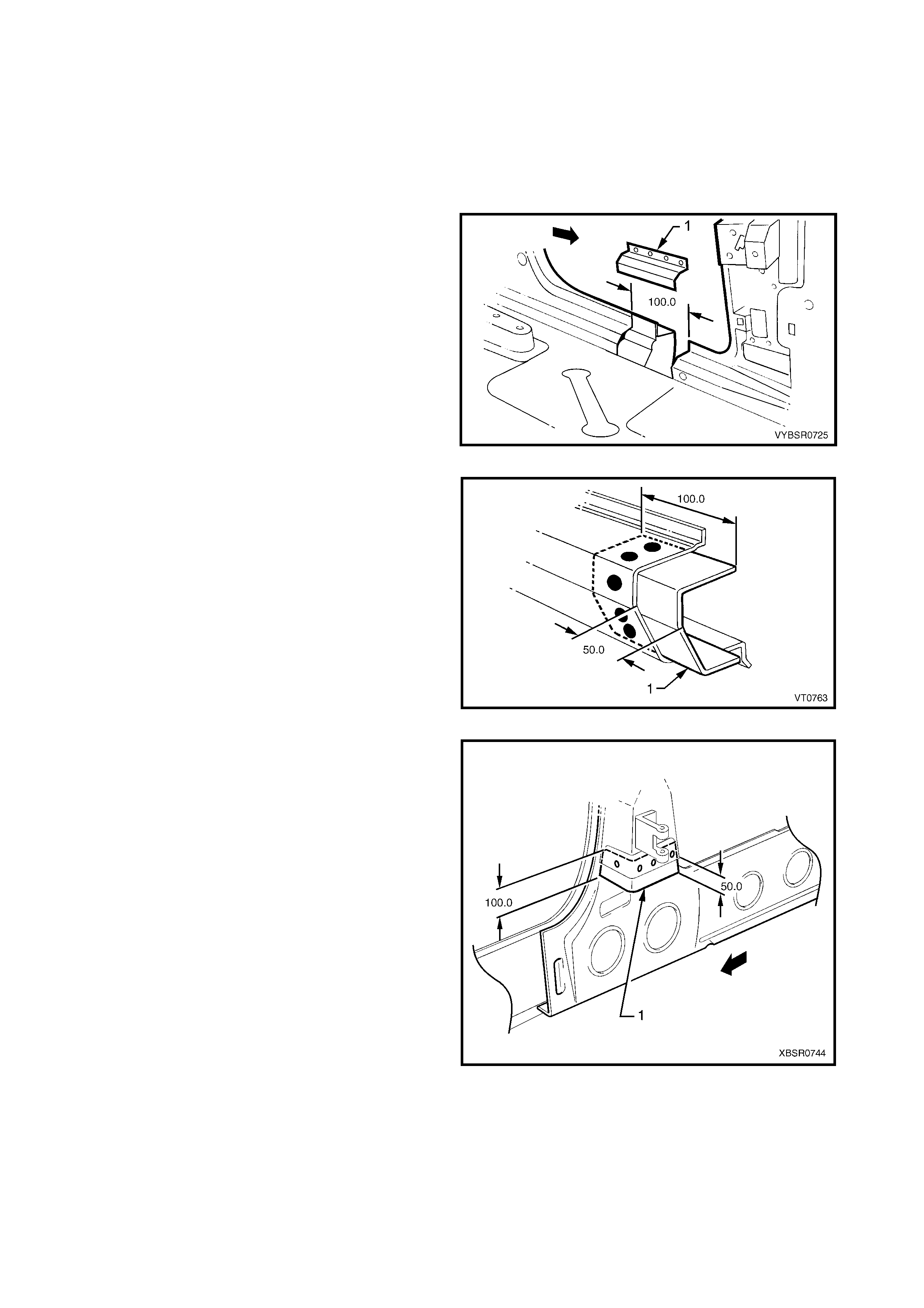
1. For the right-hand side, if required spot or plug
weld (1) the fuel filler pipe housing to the rear
quarter panel in four places.
Figure 7A-10
2. Joggle the remaining section of rear quarter panel
to match up to the new panel as shown.
3. Modif y the new rear quarter panel to f orm the j oint
as shown. The section of panel in the drain
channel is cut to allow butt welding.
NOTE: Som e replacement pr ocedures for surrounding
panels require this section of the rear quarter panel
remain intact.
4. As required, mark the new panel with drilling
locations in prepar ation f or plug welding. Drill holes
as required.
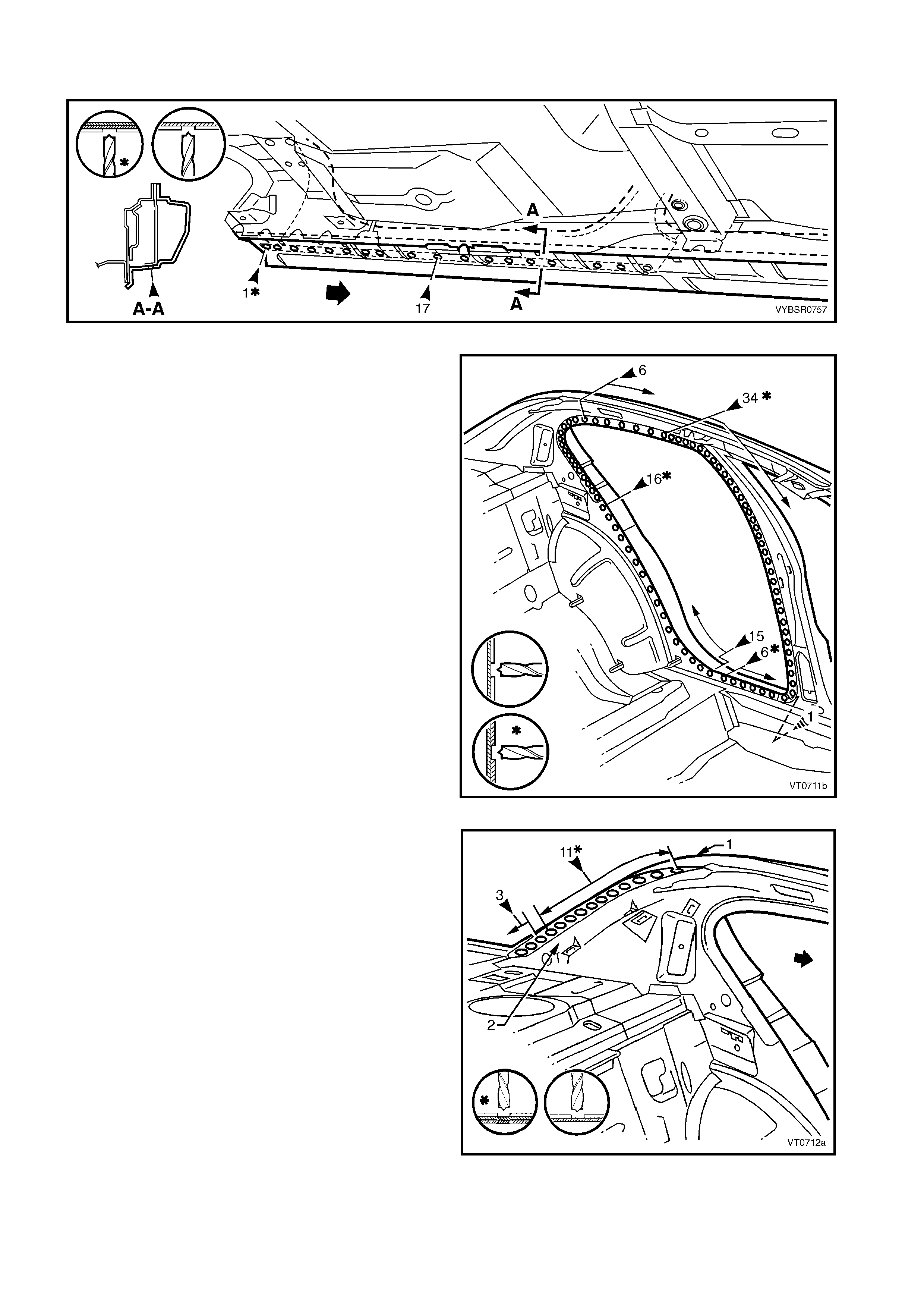
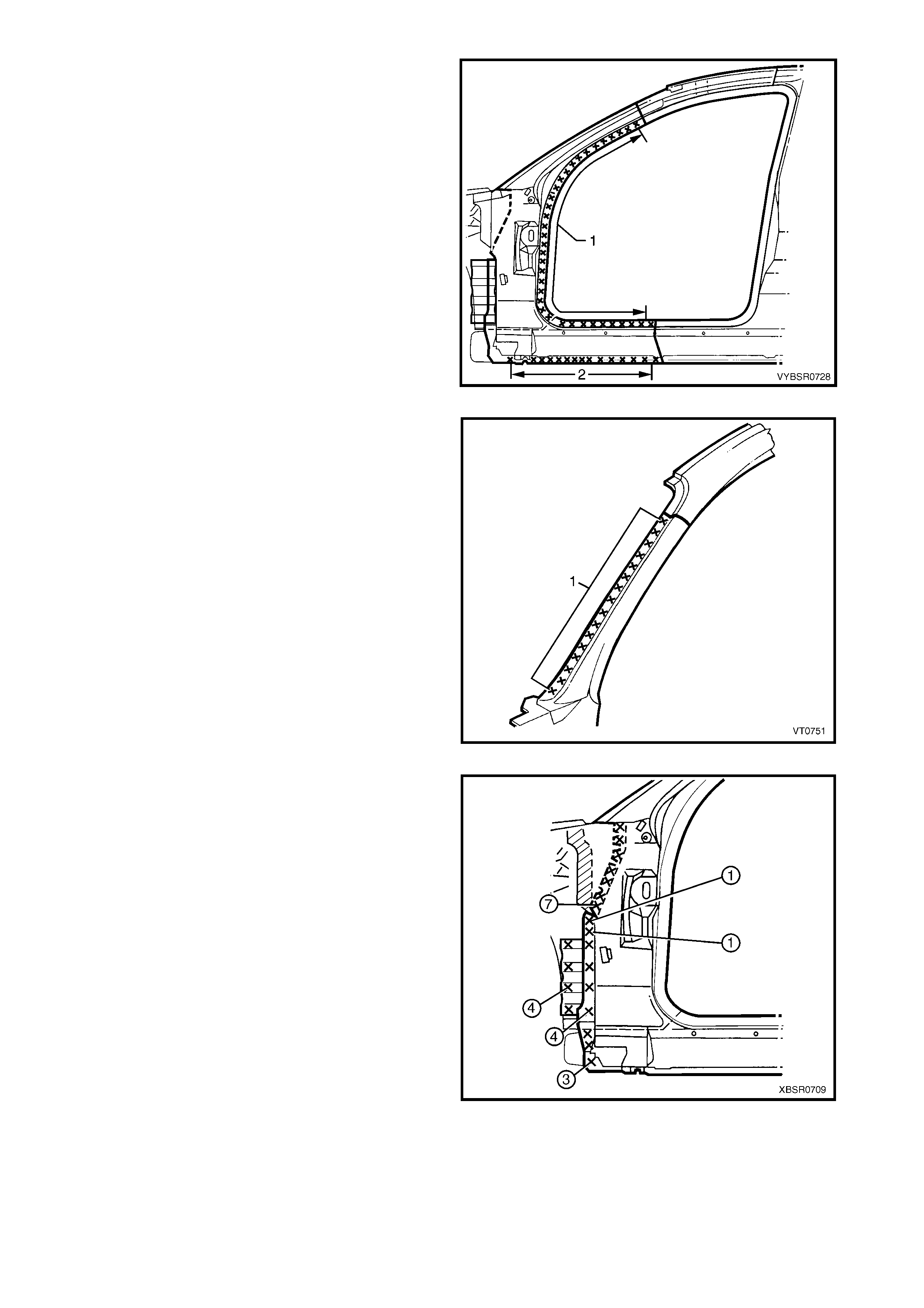
5. Prepare all mating surfaces and treat with Weld
Through Primer (Item 1) as required, refer to
5. BODY SEALING, ADHESIVES & DEADENERS
in Section 3A.
6. Apply Acrylic Spot Weld Sealer (Item 2), refer to
5. BODY SEALING, ADHESIVES & DEADENERS
in Section 3A.
7. Clamp the r ear quar ter panel in pos ition and tes t f it
the alignment with the rear door and rear
compartment lid.
8. Spot or plug weld the panels along the lap joint,
then butt weld the joint inside the channel as
shown.
Figure 7A-11
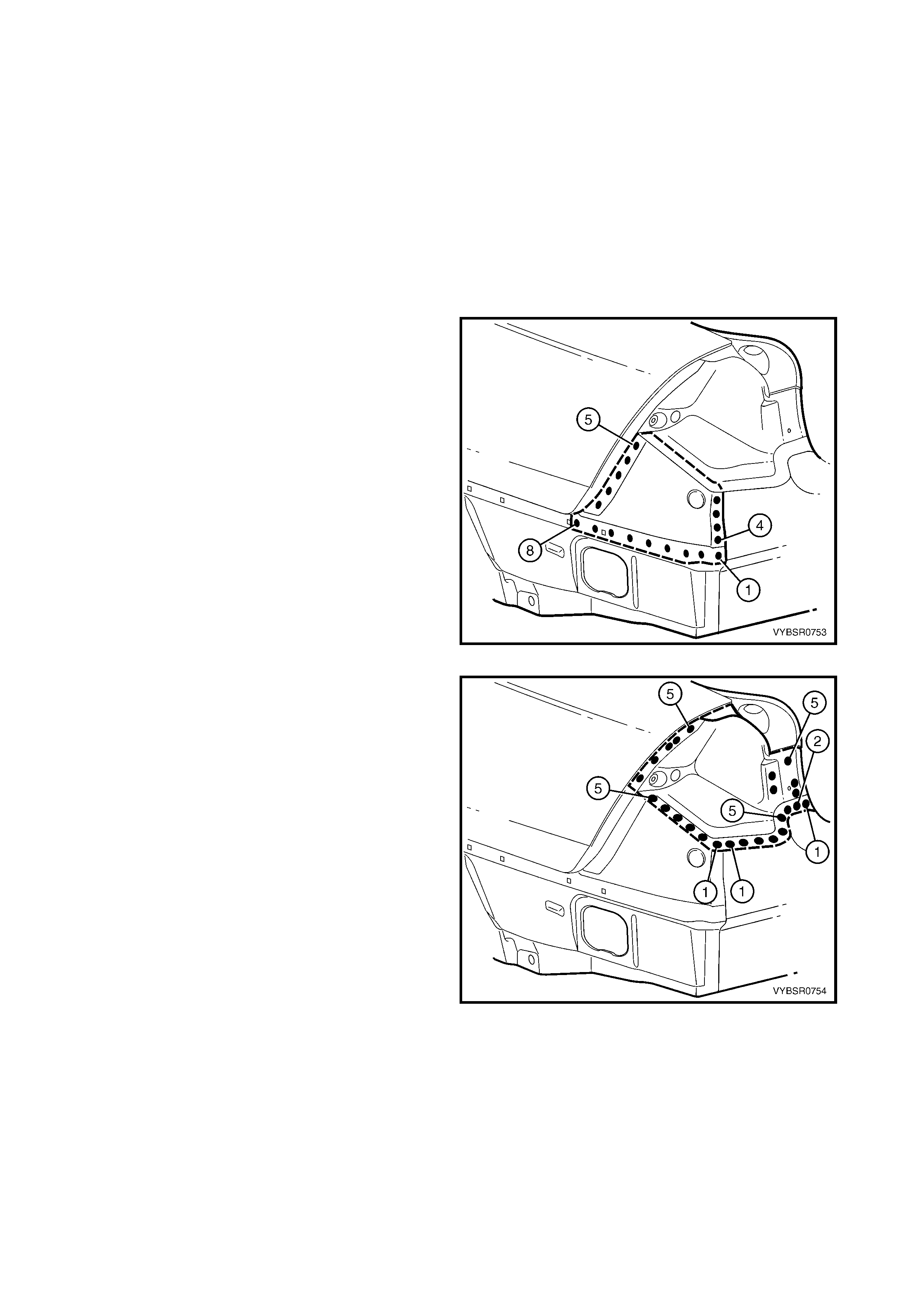
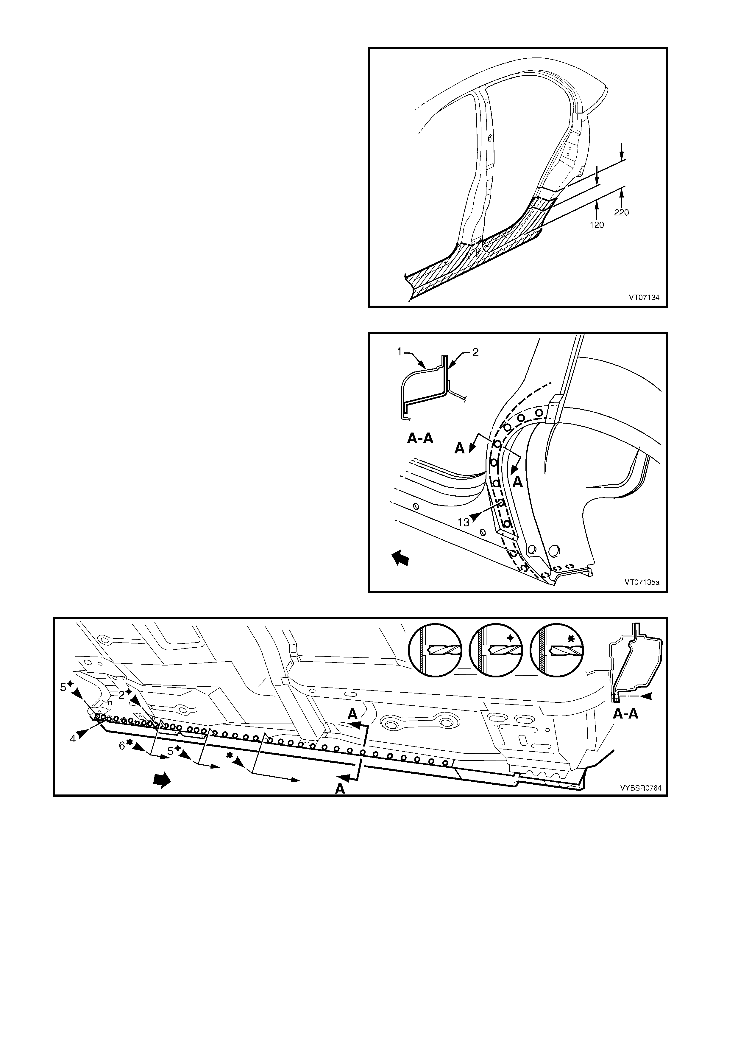
9. Spot or plug weld the rear quarter panel to the
door opening frame assembly.
10. Spot or plug weld the rear quarter panel to the
quarter inner panel as sembly. There are a dif f erent
number of welds on the left-hand panel (1) to the
right-hand panel (2), refer to Figure 7A-13.
Figure 7A-12
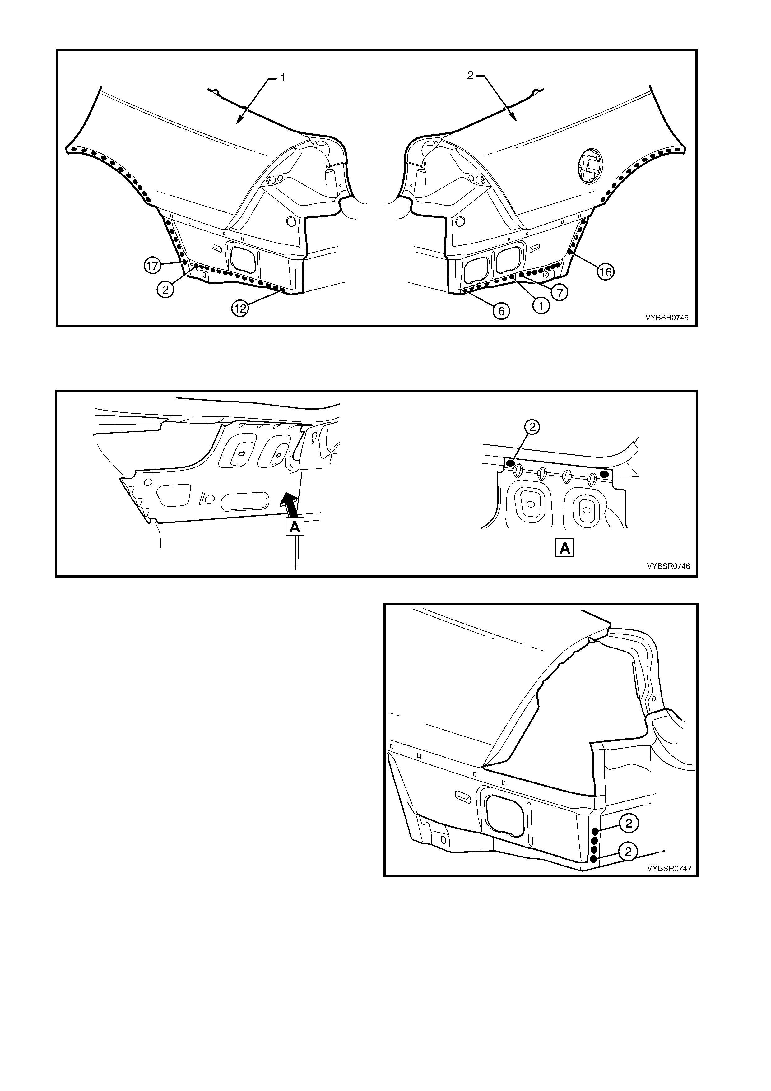
Figure 7A-13
11. Spot or plug weld the tail lamp housing brace to the rear quarter panel.
NOTE: Complete the welds to the tail lamp housing once it is installed in the following procedure.
Figure 7A-14
12. Spot or plug weld the rear quarter panel (1) to the
rear end lower panel (2).
13. Install the tail lamp housing, quarter panel upper
and lower extensions. Refer to the following
procedure.
14. Refinish and paint panels and other components
as required. Refer to Section 3, 1.3 PAINT
REFINISHING.
15. Apply Joint Sealer (Item 3) as required. Refer to
5. BODY SEALING, ADHESIVES & DEADENERS
in Section 3A.
16. Apply Cavity Wax ( Item 8) as requir ed to the inside
of any box sections or areas inaccessible to paint,
refer to 6. CAVITY WAX in Section 3A.
17. Install rear bum per impact bar, refer to Section 3,
2. BUMPER IMPACT BAR ASSEMBLIES.
18. Install the remaining components as described in
the MY 2003 VY & V2 Series II Service
Information.
Figure 7A-15
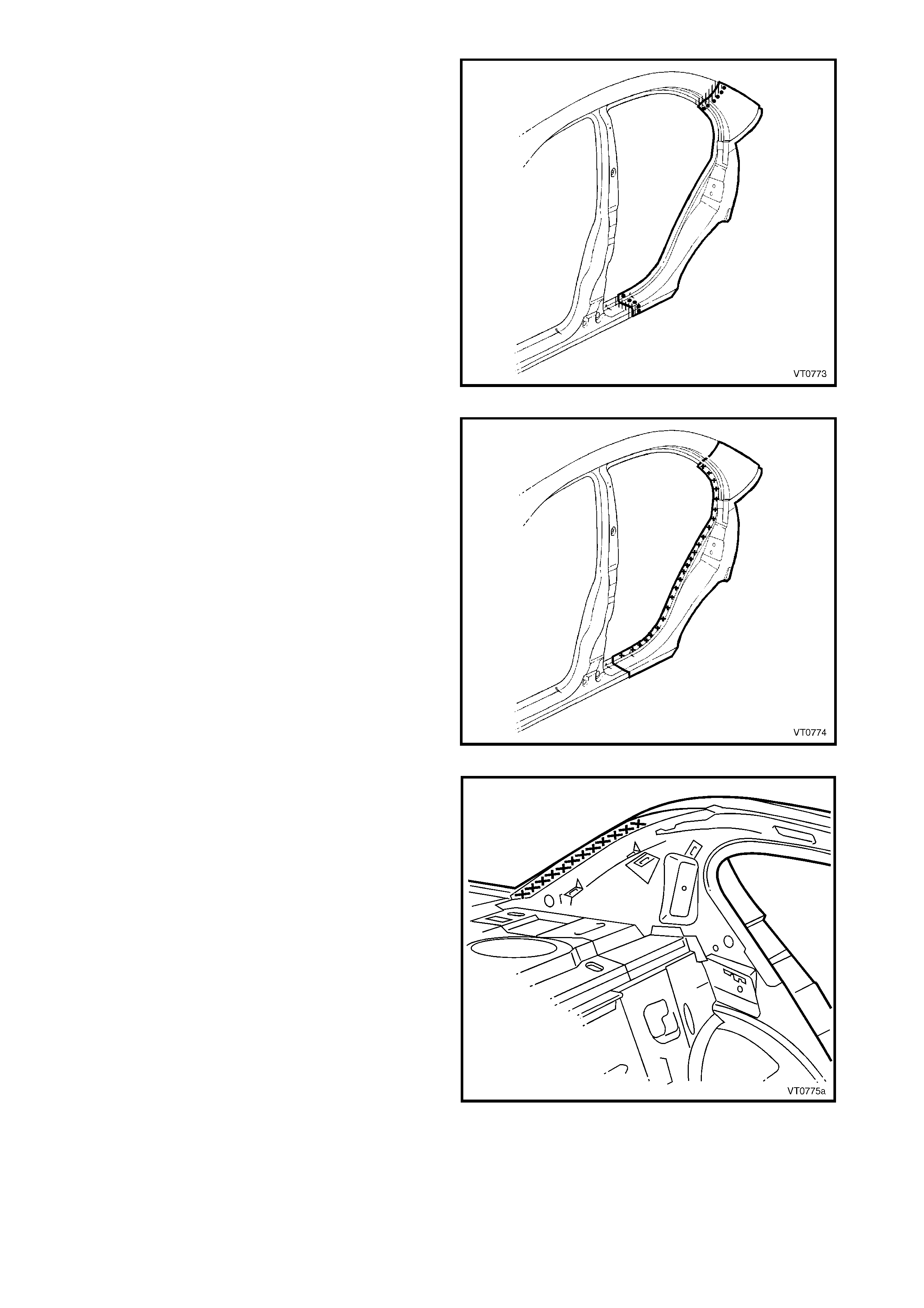
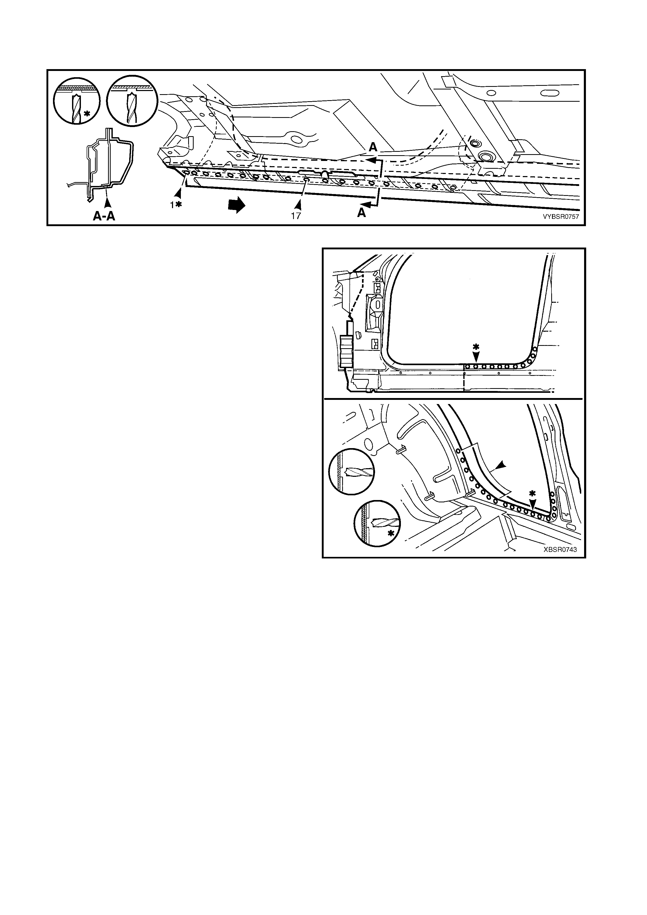
2.2 TAIL LAMP HOUSING, QUARTER PANEL LOWER EXTENSION &
QUARTER PANEL UPPER EXTENSION – REPLACE
NOTE: The components described in this procedure
may be replaced as an assembly or individually as
required.
CAUTION: To avoid the possibility of fire, take
particular care when cutting or welding at the rear
of the vehicle. Remove the fuel tank and plug all
fuel lines.
REMOVE
1. Remove the adjacent bolt-on panels and
components as described in the appropriate
Section of the MY 2003 VY & V2 Series II Service
Information.
Figure 7A-16
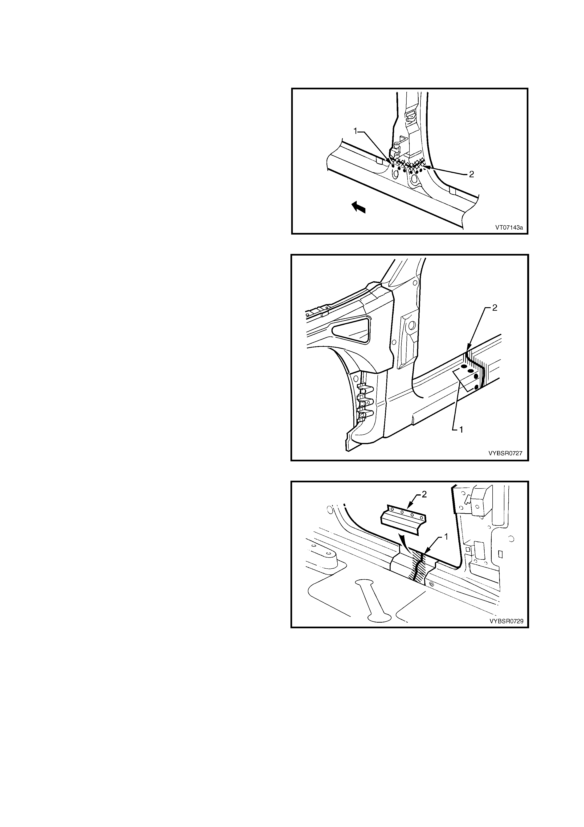
2. Spot cut the welds attaching the quarter panel
upper extension as required.
3. Spot cut the welds attaching the tail lamp housing
brace to the tail lamp housing, refer to Figure
7A-18.
Figure 7A-17
Figure 7A-18
4. Spot cut the welds attaching the tail lamp housing
to the surrounding panels as required.
Figure 7A-19
5. Spot cut the welds attaching the quarter panel
lower extension to the surrounding panels as
required.
6. Repair any damage to adjacent parts as required.
Figure 7A-20
REPLACE
NOTE 1: Spot welding is the preferred method for attaching of panels and should be used whenever possible.
Where the spot welding equipment will not access the required weld position, a plug weld should be performed.
NOTE 2: The s ame number and pos ition of s pot welds (or plug welds) s hould be used when r eplacing the panel,
as was used during manufacture, in order to maintain the original structural strength of the vehicle.
1. As required, mark the new panel with drilling locations in preparation for plug welding. Drill holes as required.
2. Prepare all mating surfaces and treat with Weld Through Primer (Item 1) as required, refer to
5. BODY SEALING, ADHESIVES & DEADENERS in Section 3A.
3. Apply Acrylic Spot Weld Sealer (Item 2), refer to 5. BODY SEALING, ADHESIVES & DEADENERS in
Section 3A.
4. Clamp the removed parts in position and if required, temporarily install the tail lamp to check for correct fit
with the surrounding panels.
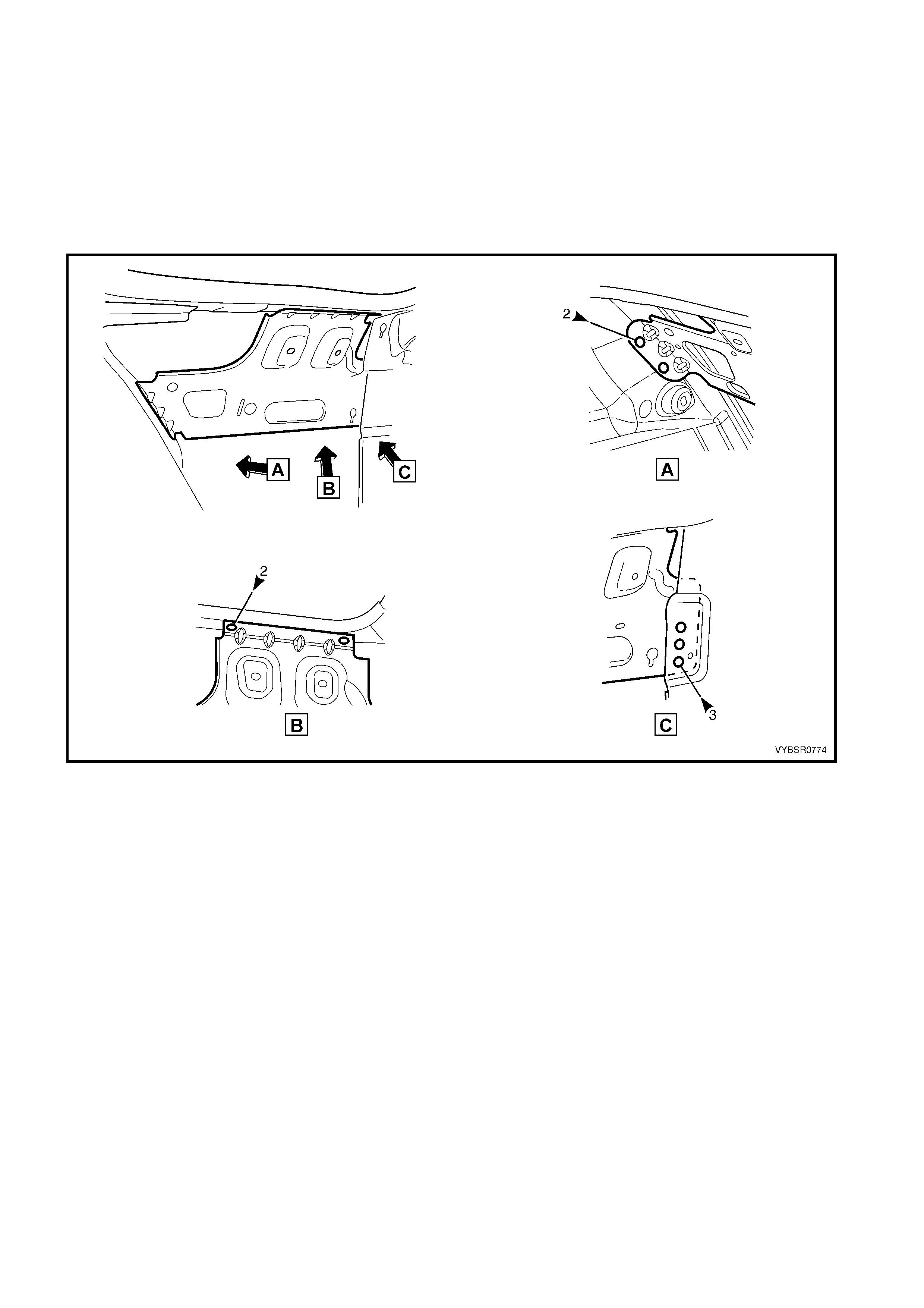
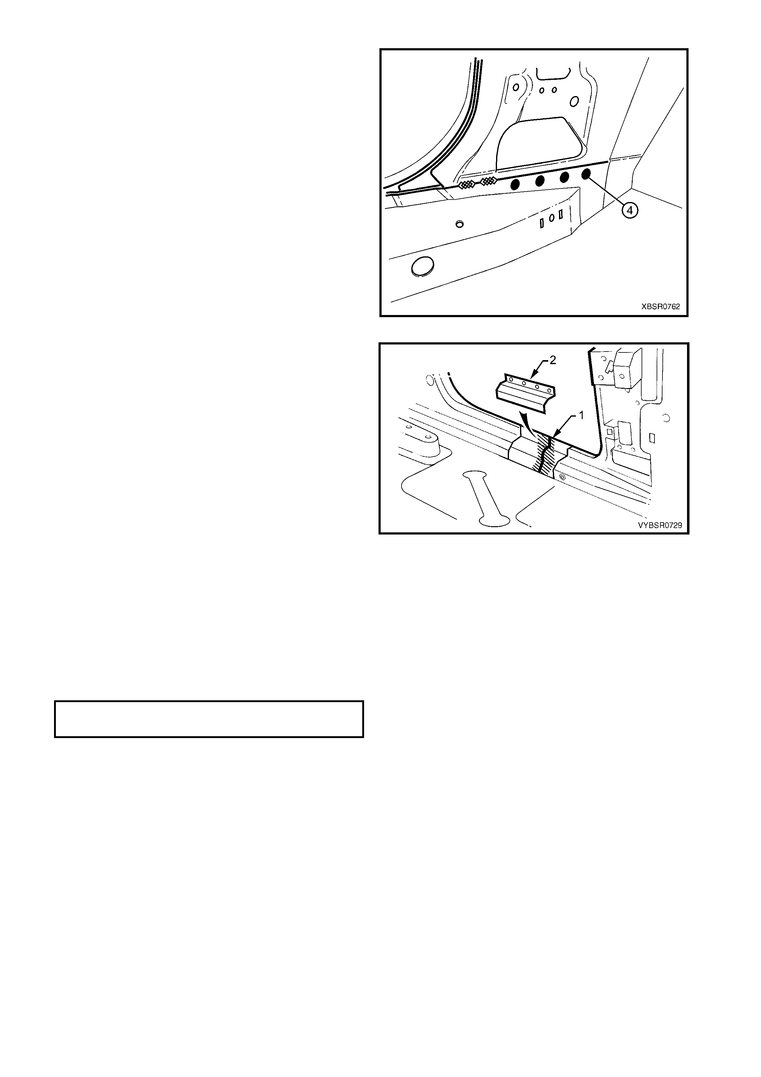
5. Spot or plug weld the quarter panel lower
extension to the surrounding panels as required.
Figure 7A-21
6. Spot or plug weld the tail lamp housing to the
surrounding panels as required.
7. Spot or plug weld the tail lamp housing brace to
the tail lamp housing, refer to Figure .
Figure 7A-22
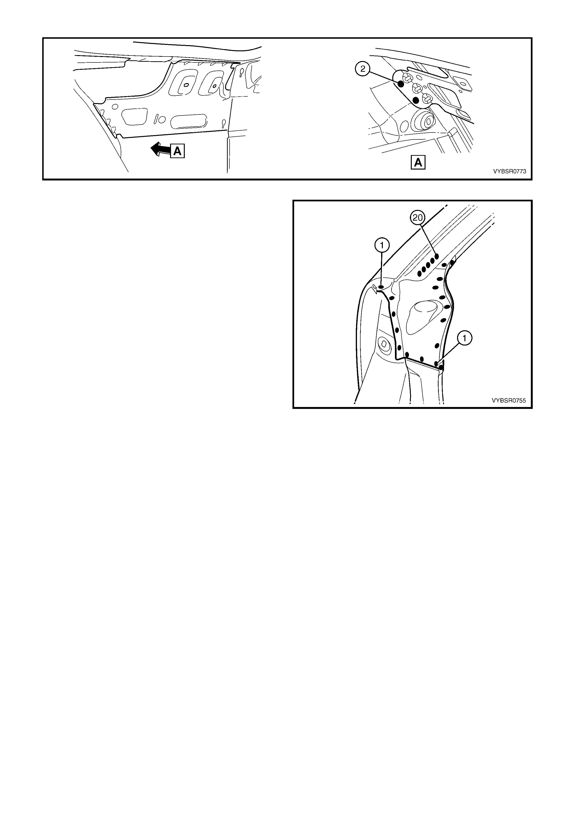
Figure 7A-23
8. Spot or plug weld the quarter panel upper
extension to the surrounding panels as required.
9. Refinish and paint panels and other components
as required. Refer to Section 3, 1.3 PAINT
REFINISHING.
10. Apply Joint Sealer (Item 3) before the top paint
coats as required, refer to 5. BODY SEALING,
ADHESIVES & DEADENERS in Section 3A.
11. Apply Cavity Wax ( Item 8) as requir ed to the inside
of any box sections or areas inaccessible to paint,
refer to 6. CAVITY WAX in Section 3A.
12. Install the remaining components as described in
the appropriate Section of the MY 2003 VY & V2
Series II Service Information.
Figure 7A-24
2.3 TAIL LAMP HOUSING BRACE – REPLACE
REMOVE
CAUTION: To av oid the possibility of fire, take particular care when cut ting or welding at the rear of the
vehicle. Remove the fuel tank and plug all fuel lines.
1. Remove the adjacent bolt-on panels and components as described in the appropriate Section of the
MY 2003 VY & V2 Series II Service Information.
2. Spot cut the tail lam p hous ing br ace f rom the tail lam p hous ing (A), r ear quarter panel ( B) and quarter panel
inner assembly (C) as required, refer to Figure 7A-25.
Figure 7A-25
3. Remove the panel from the vehicle, and then repair any damage to adjacent parts.
REPLACE
NOTE 1: Spot welding is the preferred method for attaching of panels and should be used whenever possible.
Where the spot welding equipment will not access the required weld position, a plug weld should be performed.
NOTE 2: The s ame number and pos ition of s pot welds (or plug welds) s hould be used when r eplacing the panel,
as was used during manufacture, in order to maintain the original structural strength of the vehicle.
1. Spot or plug weld the tail lamp hous ing brace to the tail lam p hous ing (A), r ear quarter panel (B) and quarter
panel inner assembly (C) as required, refer to Figure 7A-26.
Figure 7A-26
2. Refinish and paint panels and other components as required. Refer to Section 3, 1.3 PAINT REFINISHING.
3. Apply Joint Sealer (Item 3) as required. Refer to 5. BODY SEALING, ADHESIVES & DEADENERS in
Section 3A.
4. Apply Cavity Wax ( Item 8) as r equired to the inside of any box sections or areas inac cessible to paint, ref er
to 6. CAVITY WAX in Section 3A.
5. Install the remaining components as described in the MY 2003 VY & V2 Series II Service Information.
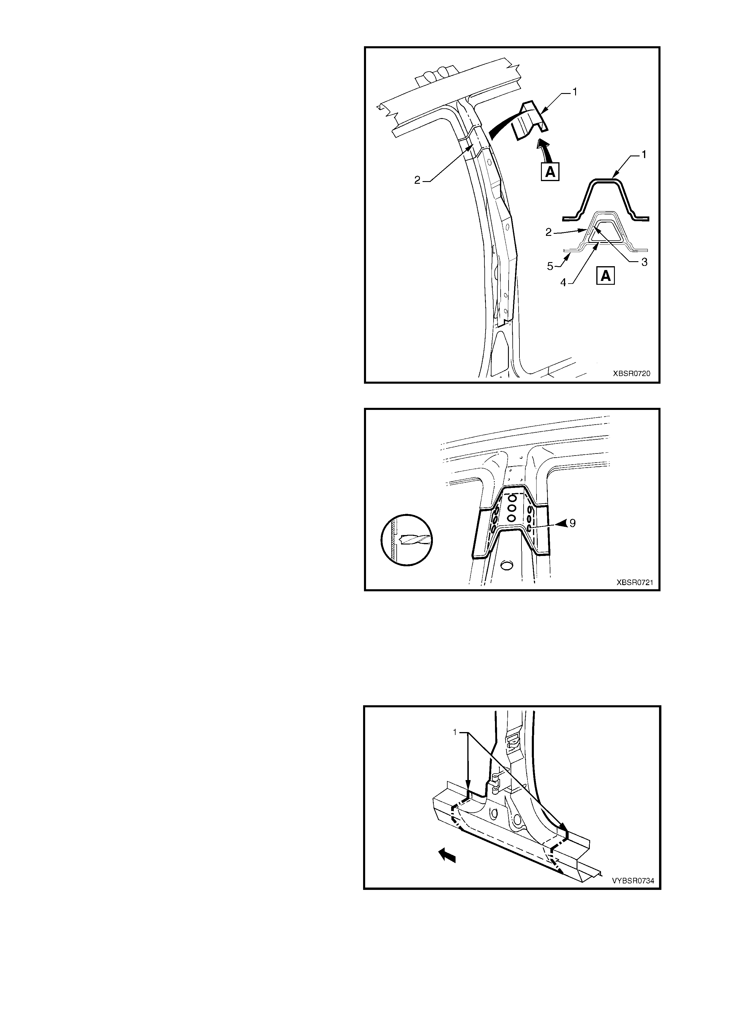
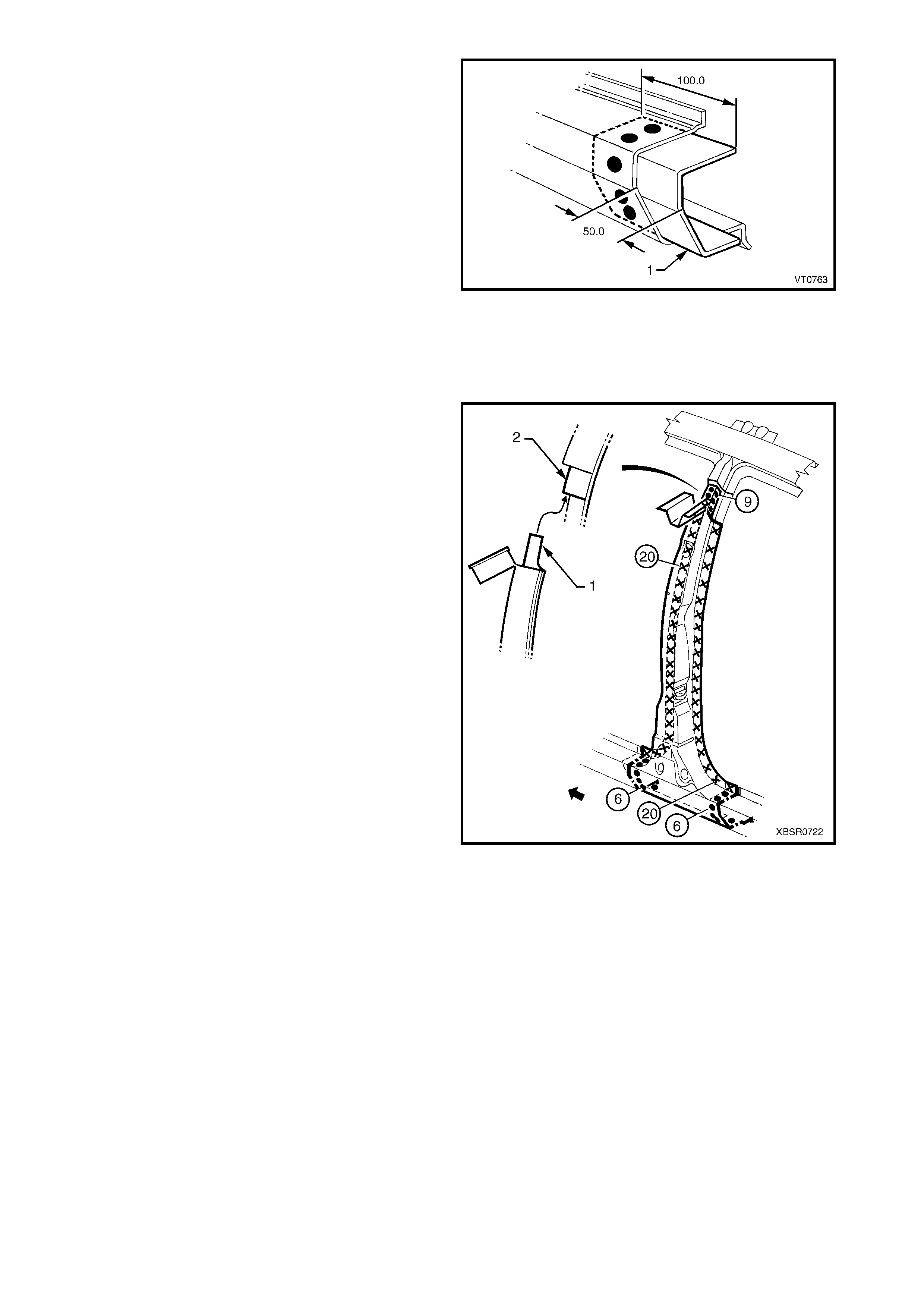
2.4 DOOR OPENING FRAME ASSEMBLY – REPLACE
NOTE 1: This procedure requires the removal of the
roof panel. As an alternative, the door opening frame
assembly can be cut at the upper pillar sections by
following the procedures in:
2.5 DOOR OPENING FRAME ASSEMBLY –
PARTIAL REPLACE, HINGE PILLAR,
2.6 DOOR OPENING FRAME ASSEMBLY –
PARTIAL REPLACE, CENTRE PILLAR and
2.7 DOOR OPENING FRAME ASSEMBLY –
PARTIAL REPLACE, LOCK PILLAR.
NOTE 2: Cavity Foam is used within the hinge, centre
and lock pillar cavities . Care is r equired when repairing
the vehicle in these areas, refer to Section 2,
10. CAVITY FOAM prior to beginning any work for
further information.
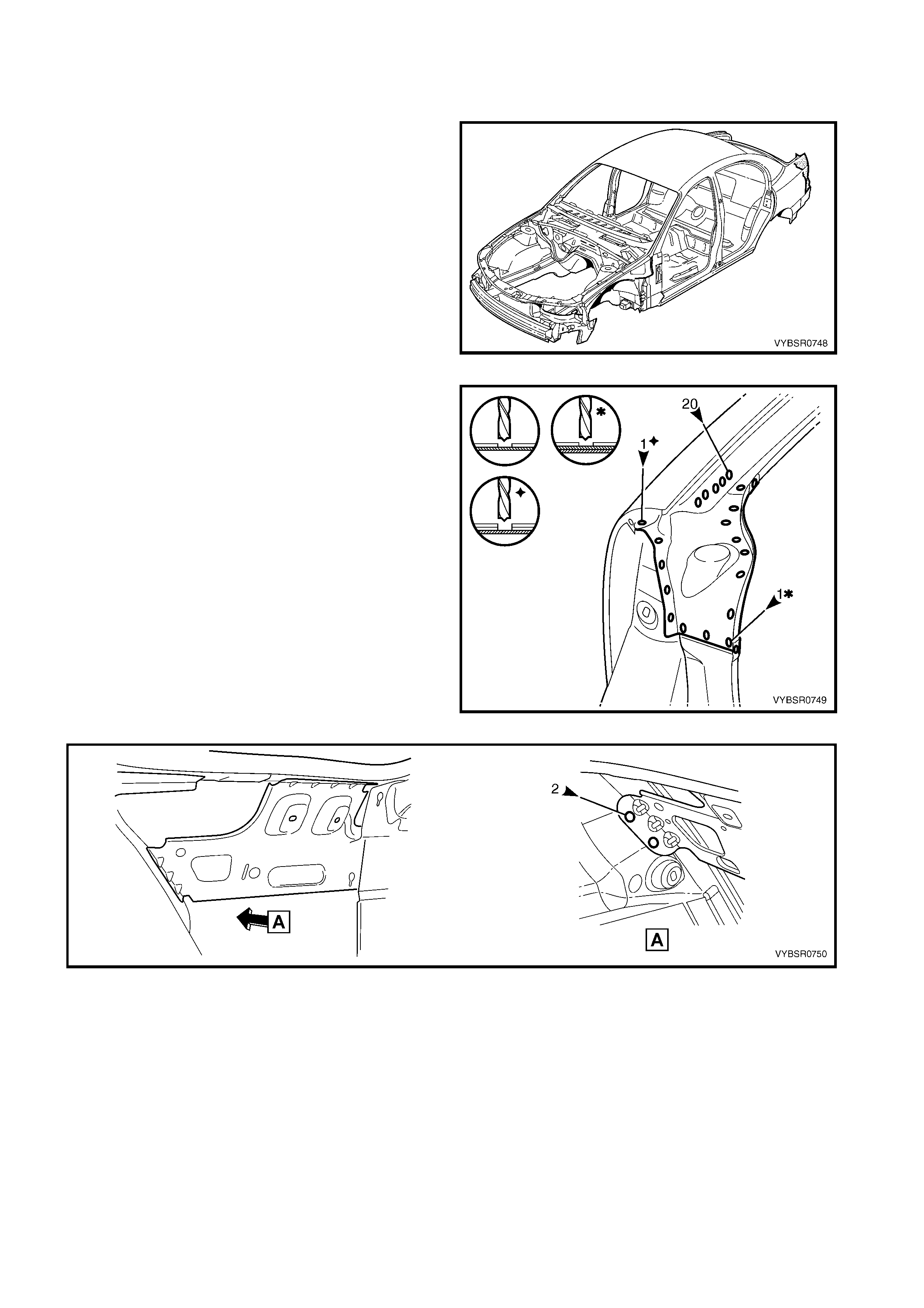
REMOVE
1. Remove the adjacent bolt-on panels and
components as described in the appropriate
Section of the MY 2003 VY & V2 Series II Service
Information.
2. Remove the windshield and the rear window
assemblies, refer to Section 1A6, STATIONARY
WINDOWS in the MY 2003 VY & V2 Series II
Service Information.
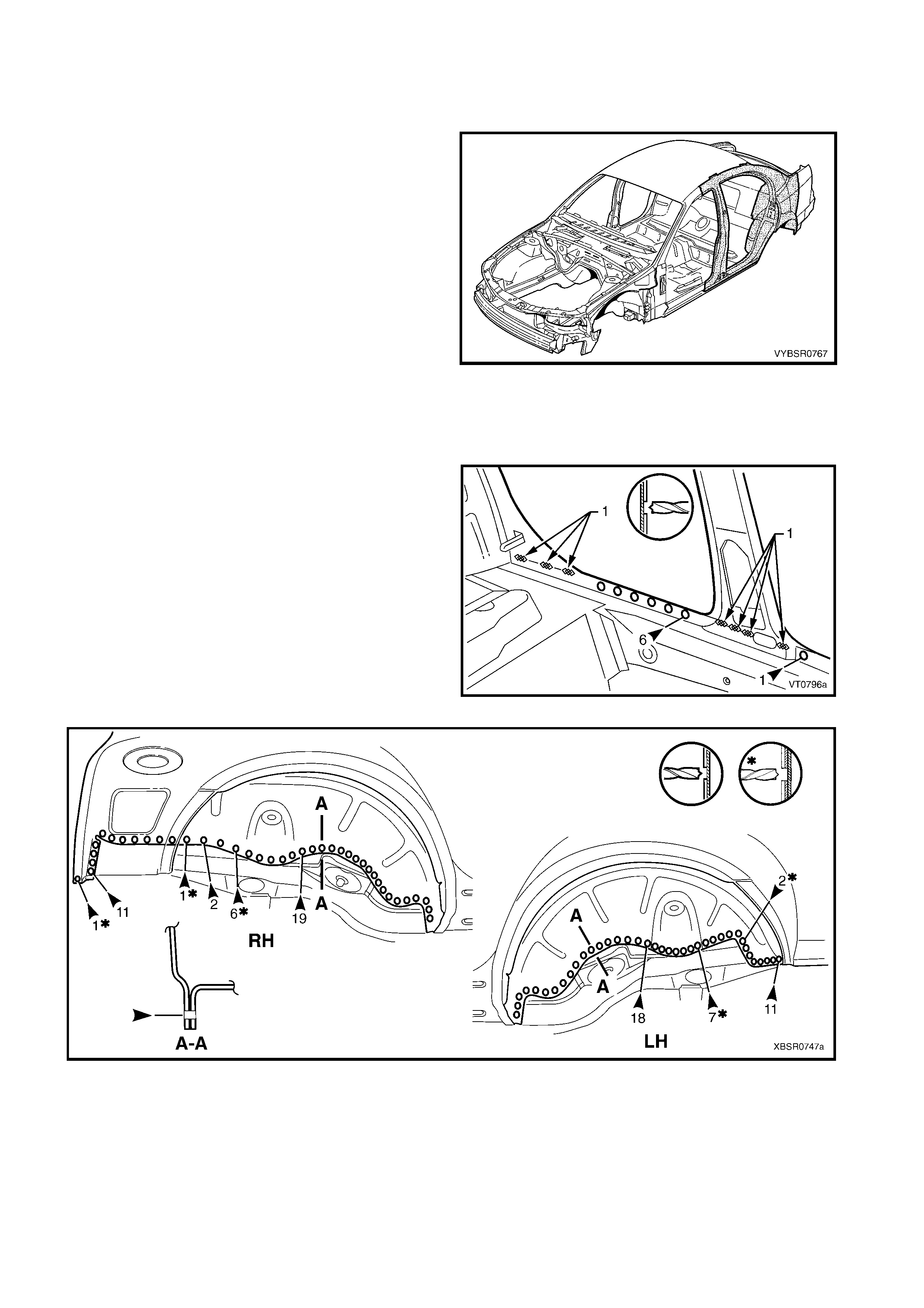
Figure 7A-27
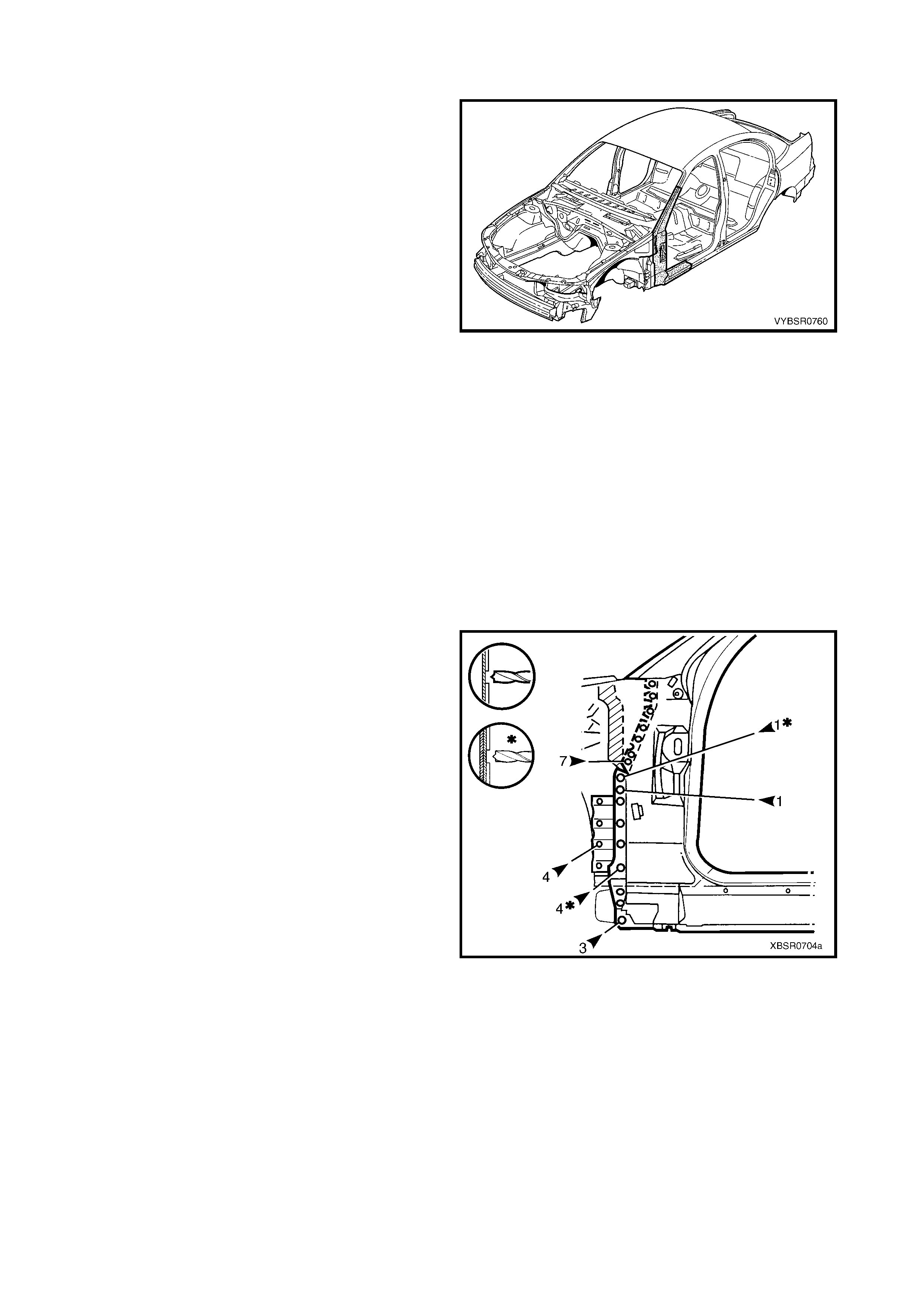
3. Remove the dash panel retaining bolt from the
hinge pillar.
4. Remove the roof panel, refer to Section 9, ROOF.
5. Rem ove the rear quarter panel, refer to 2.1 REAR
QUARTER PANEL – REPLACE.
6. Remove the front wheelhouse panel upper side
rail, refer to Section 4. 2.5 FRONT
WHEELHOUSE PANEL UPPER SIDE RAIL.
7. Spot cut the welds attaching the door opening
frame assembly to the inner rocker panel and to
the hinge pillar inner panel assembly.
NOTE: In order to spot cut the uppermost of these
welds it may be necessary to cut and peel back the
section of hinge reinforcement panel covering the
welds, to gain the required access.
8. Spot cut the welds attaching the inner rocker panel
(1) and hinge pillar inner panel as semb ly (2) to the
rock er panel r einf orc ement (3) . Ref er to Figur e 7A-
29.
NOTE: It is not required to cut the MIG welds.
Figure 7A-28
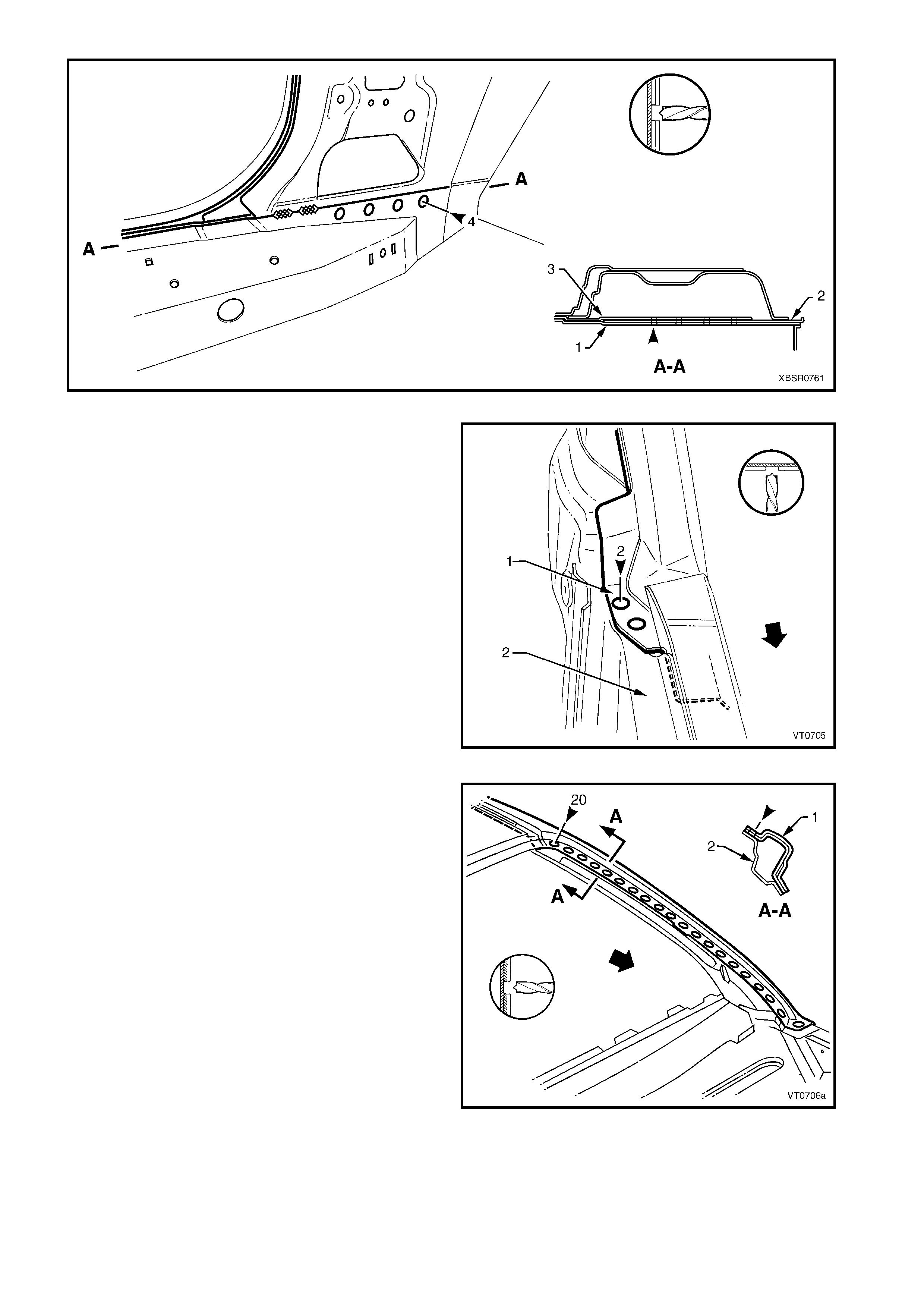
Figure 7A-29
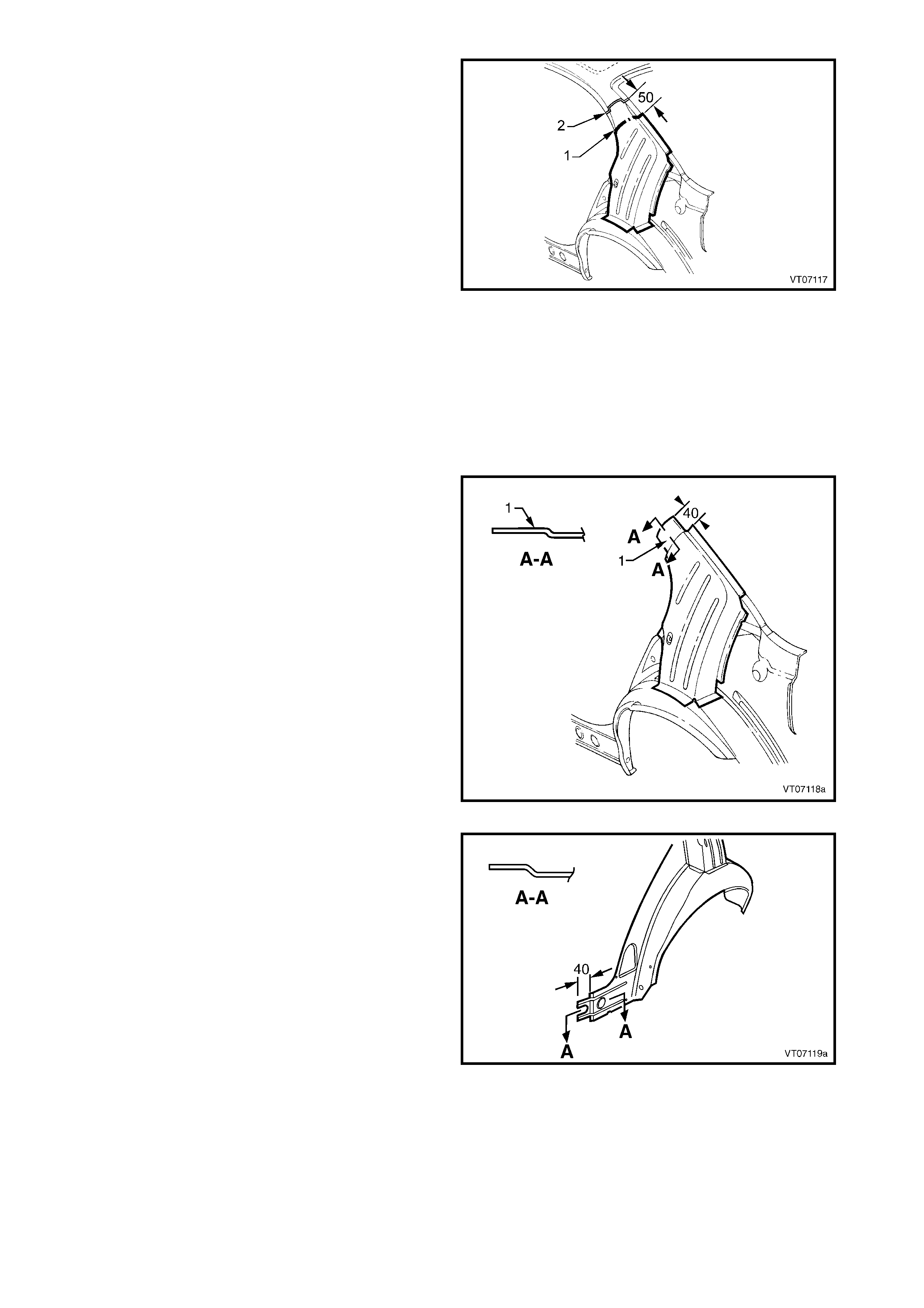
9. Spot cut the two welds at the base of the hinge
pillar, attaching the door opening frame assembly
(1) to the hinge pillar inner panel assembly (2).
Figure 7A-30
10. Spot cut the welds on the windshield side flange,
attaching the door opening frame assembly (1) to
the hinge pillar inner panel assembly (2).
Figure 7A-31
11. Spot cut the welds on the flange surrounding the
front door opening, attaching the door opening
frame assembly to the hinge pillar inner panel
assembly, inner rocker panel and quarter panel
inner assembly.
Figure 7A-32
12. Spot cut the welds around the rear wheel arch
joining the door opening f ram e assem bly (1) to the
quarter panel inner assembly (2).
13. Spot cut along the vertical f lange below the rocker
panel to separate the door opening frame
assembly from the inner rocker panel and rear
floor panel outer extension. Refer to Figure 7A-34.
Figure 7A-33
Figure 7A-34
14. Spot cut from below, up into the rocker panel, the welds attaching the door opening fram e assembly to the
quarter panel inner assembly, refer to Figure 7A-35.
Figure 7A-35
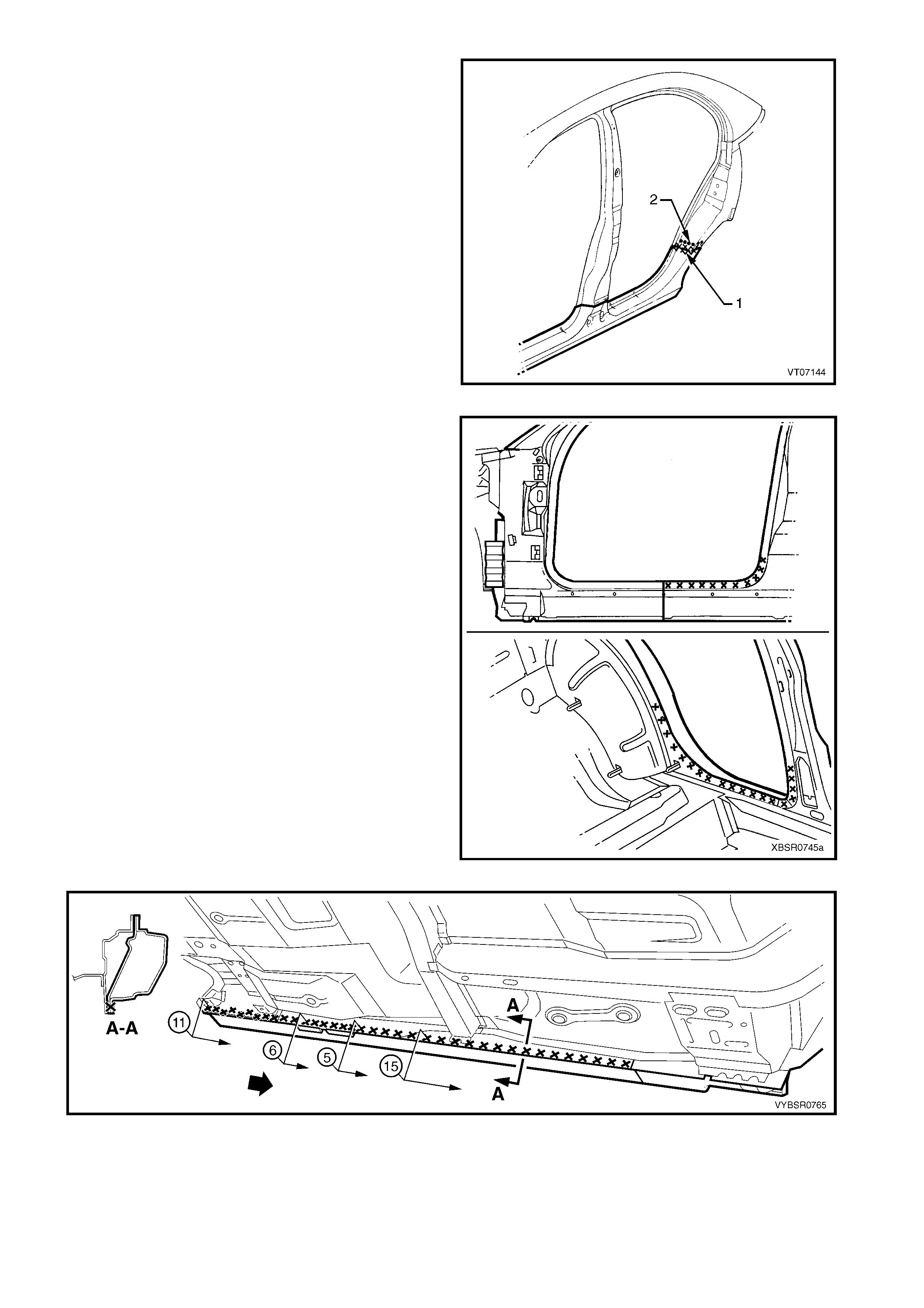
15. Spot cut the welds around the rear door opening
flange.
Figure 7A-36
16. Spot cut the welds along the rear window flange
attaching the door opening frame assembly (1) to
the quarter panel inner assembly (2).
Figure 7A-37
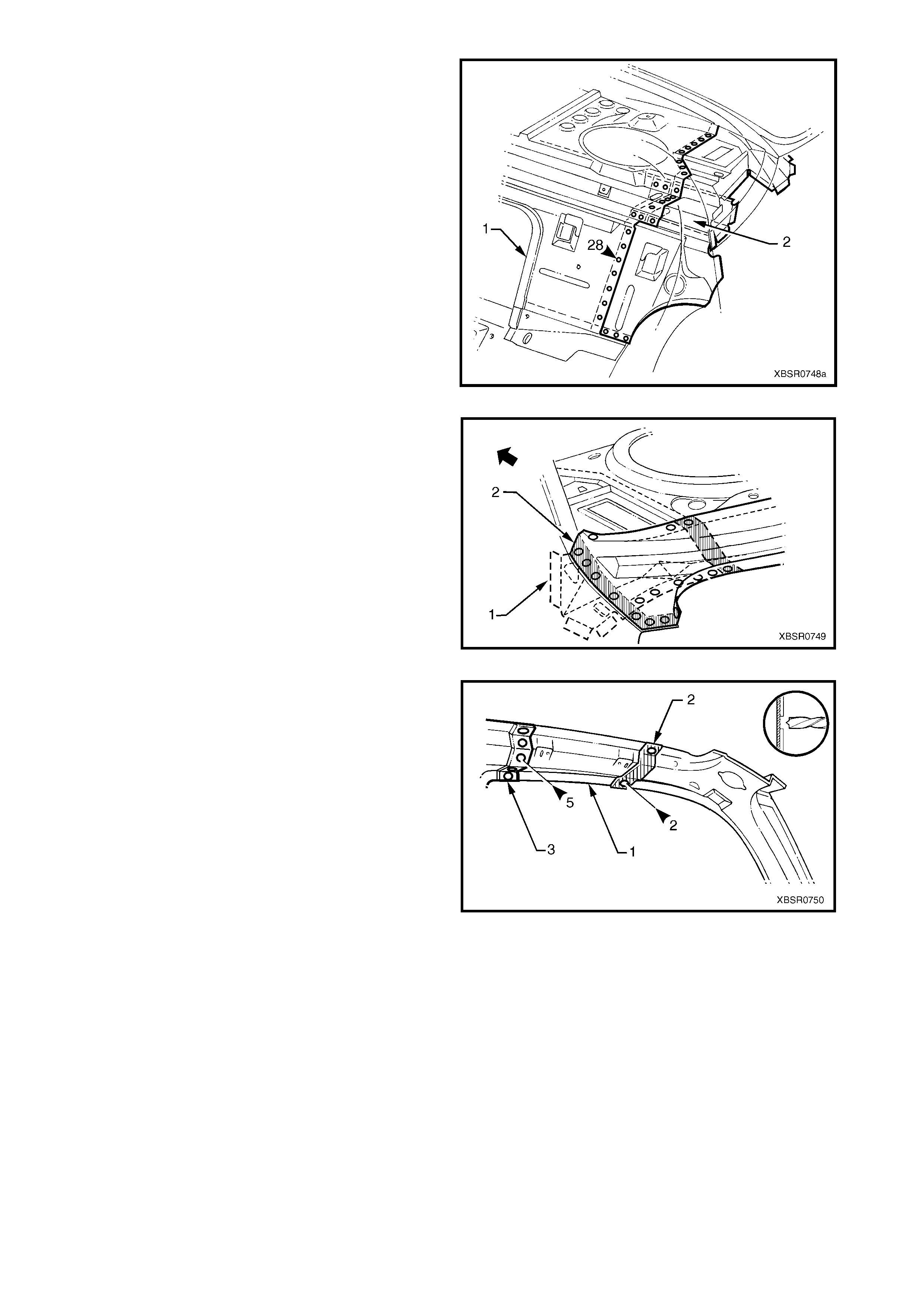
17. Spot cut the two welds attaching the roof bow
panel (2) to the centre pillar upper reinforcement,
and the s ingle weld attaching the roof bow panel to
the door opening frame assembly (1).
Figure 7A-38
18. Carefully lifting the roof bow panel out of the way,
spot cut the two welds attaching the centre pillar
upper reinforcement to the quarter panel inner
assem bly. The centre pillar upper reinforcement is
removed as part of the door opening frame
assembly.
Figure 7A-39
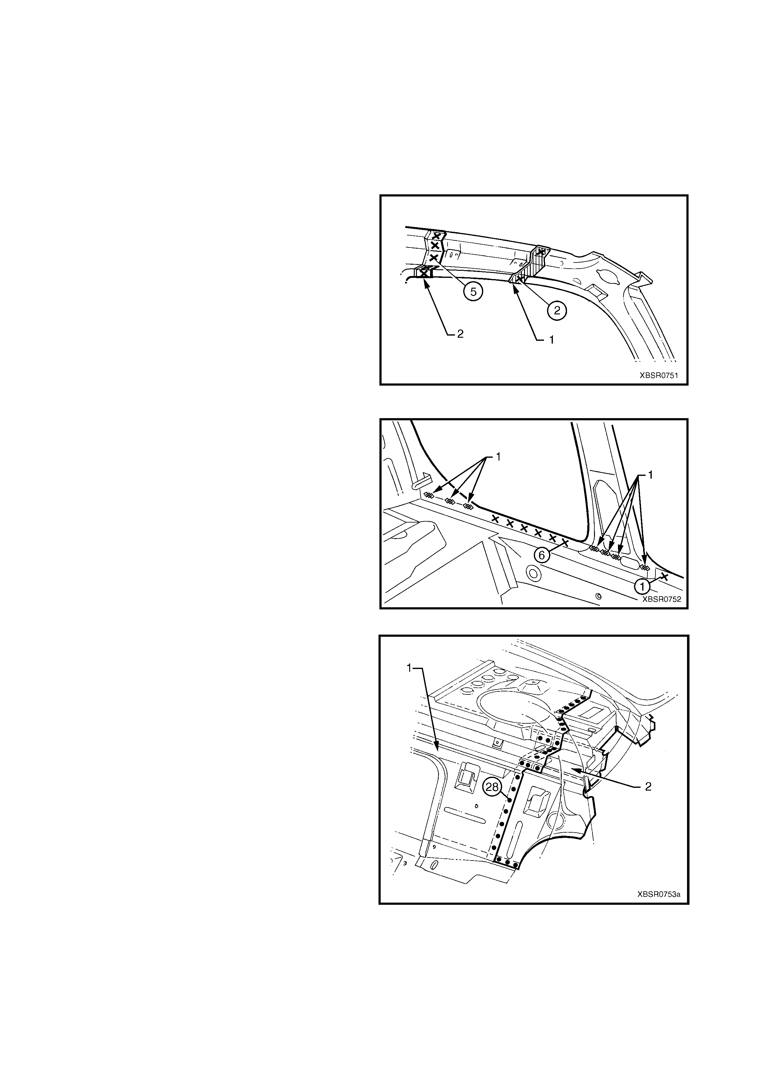
19. Spot cut the welds along the roof flange, attaching
the door opening frame assembly to the quarter
panel inner assembly.
NOTE: Many welds may have been removed with the
roof panel.
20. Remove the complete door opening frame
assembly and repair any damage to adjacent
parts.
21. Check and rectify the alignment of the body as
required, refer to 3. BODY DIMENSIONS in
Section 3A.
Figure 7A-40
REPLACE
NOTE 1: Spot welding is the preferred method for attaching of panels and should be used whenever possible.
Where the spot welding equipment will not access the required weld position, a plug weld should be performed.
NOTE 2: The same number and pos ition of s pot welds (or plug welds) s hould be used when replacing the panel,
as was used during manufacture, in order to maintain the original structural strength of the vehicle.
1. As required, mark the new panel with drilling locations in preparation for plug welding. Drill holes as required.
2. Prepare all mating surfaces and treat with Weld Through Primer (Item 1) as required, refer to
5. BODY SEALING, ADHESIVES & DEADENERS in Section 3A.
3. Apply Acrylic Spot Weld Sealer (Item 2), refer to 5. BODY SEALING, ADHESIVES & DEADENERS in
Section 3A.
4. Securely clamp the door opening frame assembly
in position on the vehicle body.
5. Begin attaching the door opening frame assembly
by spot welding around the front door opening
flange.
Figure 7A-41
6. Spot weld around the flange of the rear door
opening.
Figure 7A-42
7. Spot or plug weld around the rear wheel arch,
attaching the door opening frame assembly to the
quarter panel inner assembly.
Figure 7A-43
8. Spot or plug weld the door opening frame
assembly to the inner rocker panel and to the
hinge pillar inner panel ass embly. If the sheetmetal
was modified to allow access to these welds, it
should be repaired to its original configuration.
Figure 7A-44
9. Plug weld the inner rocker panel and hinge pillar
inner panel assembly to the rocker panel
reinforcement.
Figure 7A-45
10. Spot or plug weld the door opening frame
assembly (1) to the hinge pillar inner panel
assembly (2) at the base of the hinge pillar.
Figure 7A-46
11. Spot or plug weld the rear window flange to the
door opening frame assembly (1) and quarter
panel inner assembly (2).
Figure 7A-47
12. Spot or plug weld along the windshield flange,
attaching the door opening frame assembly (1) to
the hinge pillar inner panel assembly (2).
Figure 7A-48
13. Spot or plug weld the door opening frame
assembly (1) to the quarter inner panel assembly,
then spot or plug weld the roof bow panel (2) to the
door opening frame assembly as shown.
Figure 7A-49
14. Spot or plug weld the door opening frame
assembly to the quarter inner panel assembly
along the roof panel flange. Complete this flange
when installing the roof panel.
15. Spot or plug weld the door opening frame
assembly along the vertical flange below the
rocker panel, refer to Figure 7A-51.
Figure 7A-50
Figure 7A-51
16. Plug weld up through the rock er panel to attach the door opening fram e assem bly to the quarter panel inner
assembly. Refer to Figure 7A-52.
Figure 7A-52
17. Replace front wheelhouse panel upper side rail, refer to Section 4, 2.5 FRONT WHEELHOUSE PANEL
UPPER SIDE RAIL FRONT END – REPLACE.
18. Replace the rear quarter panel, refer to 2.1 REAR QUARTER PANEL – REPLACE.
19. Replace the roof panel, refer to Section 9, ROOF.
NOTE: Refinish and prime any bare metal as required prior to replacing these panels.
20. Install the door hinges, refer to 2.3 DOOR HINGE (BODY SIDE) – REPLACE in Section 8.
21. Refinish and paint panels and other components as required. Refer to Section 3, 1.3 PA INT REFINISHING.
22. Apply Joint Sealer (Item 3) as required. Refer to 5. BODY SEALING, ADHESIVES & DEADENERS in
Section 3A.
23. Apply Cavity W ax (Item 8) as required to the inside of any box sections or areas inac cessible to paint, ref er
to 6. CAVITY WAX in Section 3A.

24. Apply Spray-on Deadener (Item 7) where applicable, refer to 5. BODY SEALING, ADHESIVES &
DEADENERS in Section 3A.
25. Install the dash panel retaining bolt through the hinge pillar and tighten to the specified torque.
26. Replace the windshield and the rear window assembly, refer to Section 1A6, ST ATIONARY GLASS in the
MY 2003 VY & V2 Series II Service Information.
27. Insert Cavity Foam into the hinge & centre pillars as required, refer to Section 2, 10. CAVITY FOAM.
28. Install the rem aining components as described in the appropriate Sec tion of the MY 2003 VY & V2 Series II
Service Information.
DASH PANEL RETAINING BOLT
TORQUE SPECIFICATION 35.0 – 45.0 Nm
2.5 DOOR OPENING FRAME ASSEMBLY – PARTIAL REPLACE, HINGE PILLAR
IMPORTANT: A sunroof option is available that is
fitted on the production line. To cater for this option, a
stainless steel front drain tube is also fitted within the
hinge pillar cavity, therefore the partial replacement
procedure for the hinge pillar must not be performed
on these vehicles.
NOTE: Cavity Foam is used within the hinge, centre
and lock pillar cavities. Care is required when
repairing the vehicle in these areas, refer to
Section 2, 10. CAVITY FOAM prior to beginning any
work for further information.
REMOVE
1. Remove the adjacent bolt-on panels and
components as described in the appropriate
Section of the MY 2003 VY & V2 Series II Service
Information.
2. Secure an appropriate tool between the front door
opening flanges to maintain correct body
alignment.
3. Remove the windshield, refer to Section 1A6,
STATIONARY WINDOWS in the MY 2003 VY &
V2 Series II Service Information.
4. Remove the dash panel retaining bolt from the
hinge pillar.
Figure 7A-53
5. Remove the front wheelhouse panel upper side
rail, refer to Section 4, 2.5 FRONT
WHEELHOUSE PANEL UPPER SIDE RAIL.
6. Spot cut the welds attaching the door opening
frame assembly to the inner rocker panel and to
the hinge pillar inner panel assembly.
NOTE: In order to spot cut the uppermost of these
welds it may be necessary to cut and peel back the
section of hinge reinforcement panel covering the
welds, to gain the required access.
7. Spot cut the welds attaching the inner rocker panel
(1) and hinge pillar inner panel assem bly (2) to the
rock er panel reinforcement ( 3). Ref er to Figure 7A-
55.
NOTE: It is not required to cut the MIG welds.
Figure 7A-54
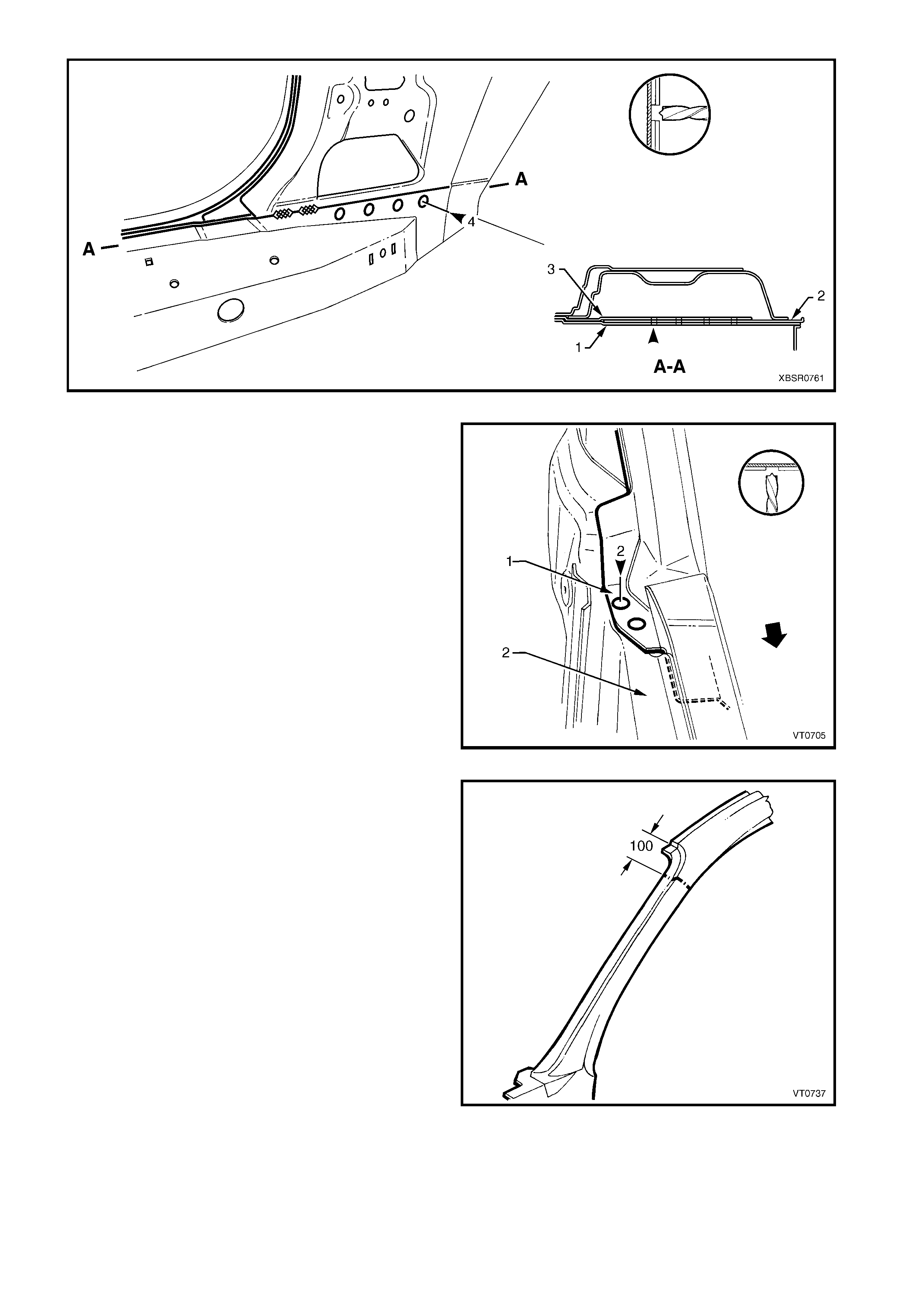
Figure 7A-55
8. Spot cut the two welds at the base of the hinge
pillar, attaching the door opening frame assembly
(1) to the hinge pillar inner panel assembly (2).
Figure 7A-56
9. Select a cutting point on the hinge pillar. This cut
point should be within the region specified.
Figure 7A-57
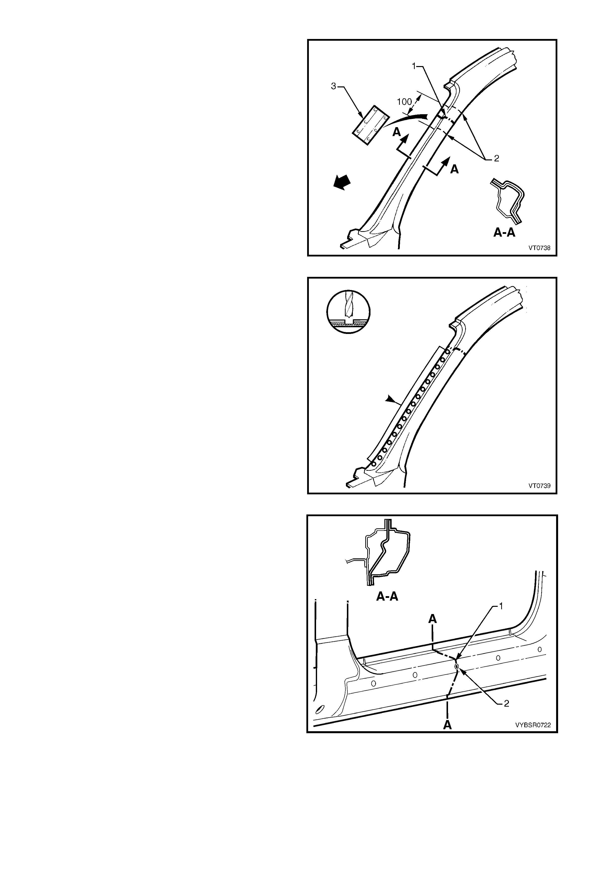
10. At the s elected point (1) , cut through the outer and
reinforcement panels, leaving the inner panel
intact.
11. Mark the inner panel at points 50 mm either side of
the cut line on the outer panel and cut the inner
panel at these two points (2). Spot cut the welds
and remove the 100 mm section of inner panel (3).
Figure 7A-58
12. Spot cut the welds on the windshield side flange,
up to the point of the cut.
Figure 7A-59
13. Cut through the rocker panel section of the door
opening frame assembly. The cut point (1) should
be through the third rocker panel moulding
attaching hole (2). Cut through both the outer
panel and the reinforcement.
Figure 7A-60
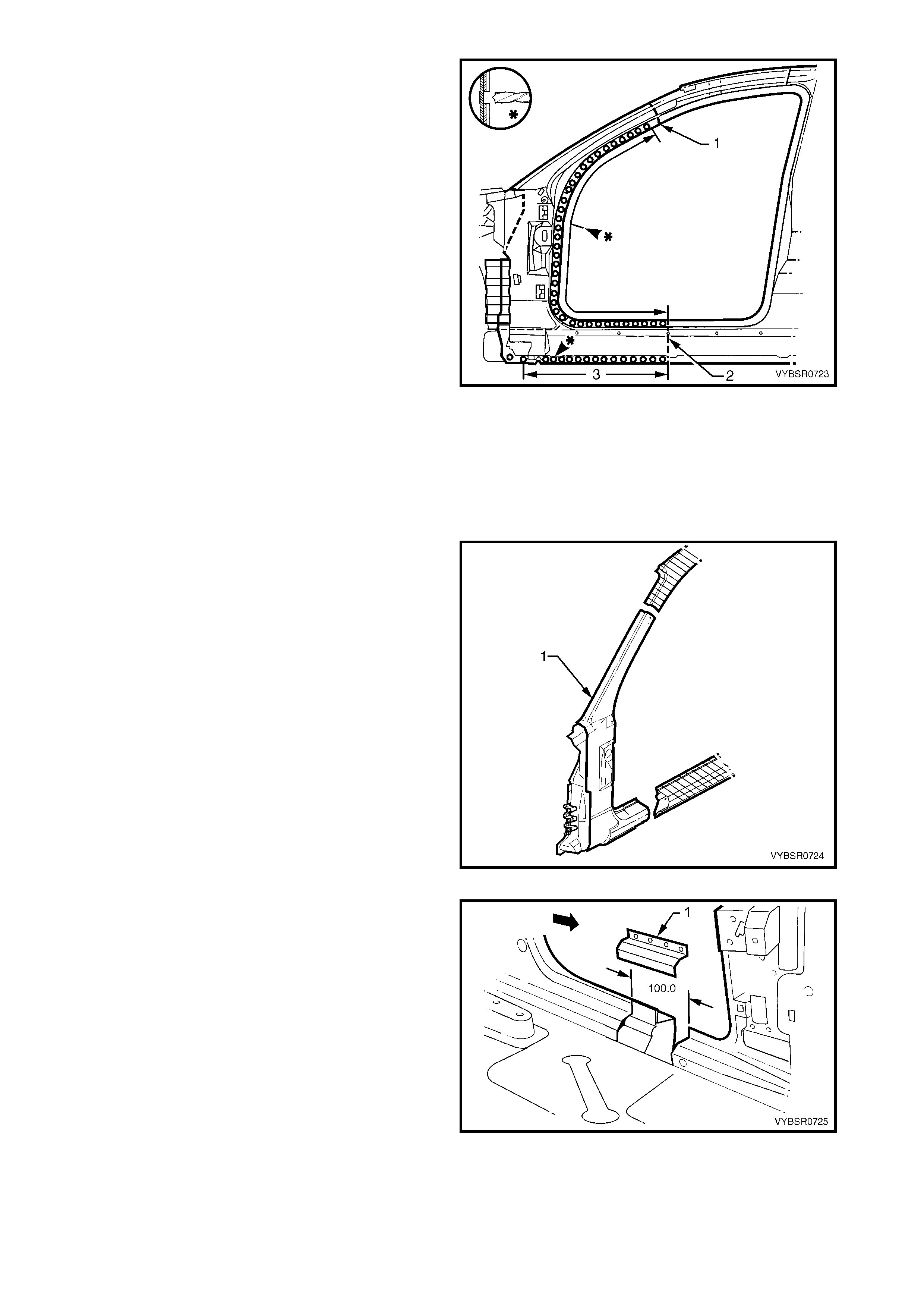
14. Spot cut the welds on the flange along the front
door opening, from the cut near the top of the
hinge pillar (1) to the cut in the rocker panel (2).
15. Spot cut the welds along the flange (3) below the
rocker panel to the point of the cut.
16. Remove the partial hinge pillar from the vehicle,
then repair any damage to adjacent parts.
17. Check and rectify the alignment of the body as
required, refer to 3. BODY DIMENSIONS in
Section 3A.
Figure 7A-61
REPLACE
NOTE 1: Spot welding is the preferred method for attaching of panels and should be used whenever possible.
Where the spot welding equipment will not access the required weld position, a plug weld should be performed.
NOTE 2: The same number and pos ition of s pot welds (or plug welds) s hould be used when replacing the panel,
as was used during manufacture, in order to maintain the original structural strength of the vehicle.
1. Cut a replacement panel section (1), accurately
measuring the position of cuts to match the section
removed.
Figure 7A-62
2. Remove a section of inner rocker panel (1). Cut
50 mm each side of the cut in the rocker panel.
This allows access for welding the rocker panel
reinforcement.
Figure 7A-63
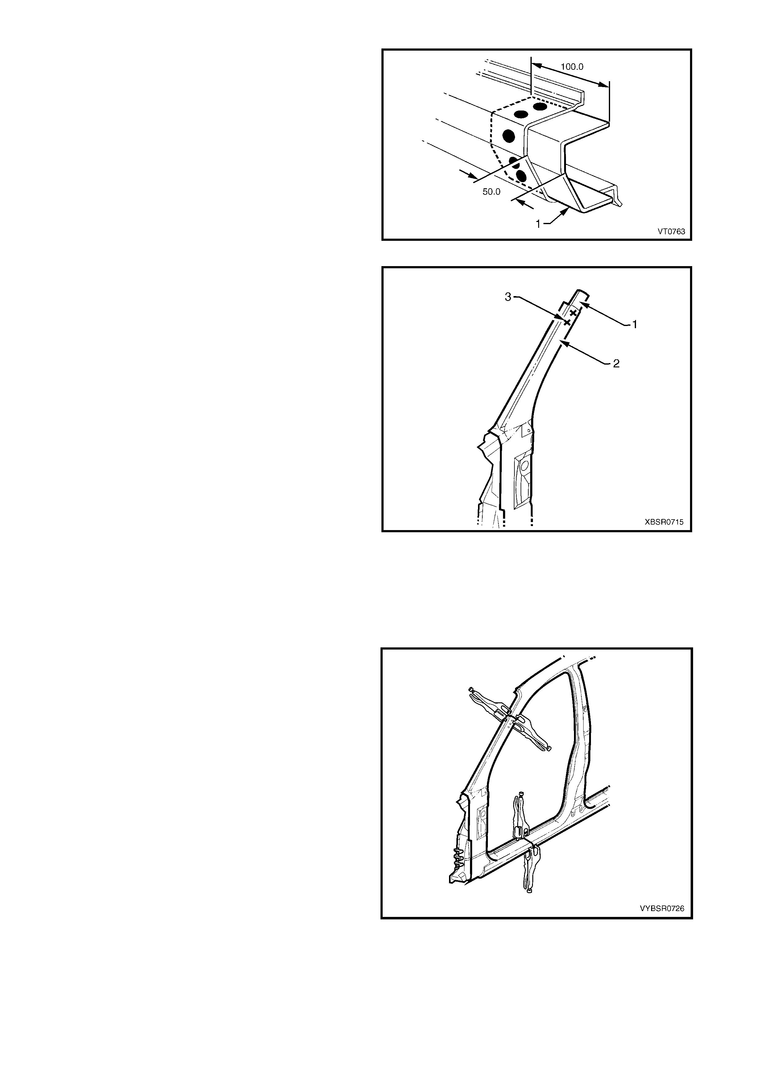
3. Either manufacture a new section or cut an
existing length of surplus rocker panel section, to
form a reinforcement (1), appr ox imately 100 mm in
length.
4. Prepare all mating surfaces and treat with Weld
Through Primer (Item 1) as required, refer to
5. BODY SEALING, ADHESIVES & DEADENERS
in Section 3A.
5. Clamp this reinforcement firmly behind the cut
section of rocker panel on the vehicle and spot or
plug weld in place. Position welds at a maximum
spacing of 35 mm apart.
Figure 7A-64
6. Using a similar technique, manufacture or cut a
section of reinforcement panel (1) approximately
60 mm long, to fit on the inside the outer panel of
the replacement hinge pillar (2) at the point of the
cut.
NOTE: Remove the flanges from this reinforcement
panel.
7. Prepare all mating surfaces and treat with Weld
Through Primer (Item 1) as required, refer to
5. BODY SEALING, ADHESIVES & DEADENERS
in Section 3A.
8. Clamp the reinforcement panel firmly behind the
outer panel of the cut section of the hinge pillar
and spot weld (3) in place.
9. Mark the new hinge pillar with drilling locations in
preparation for plug welding where required. Drill
holes as marked.
10. Prepare all mating surfaces and treat with Weld
Through Primer (Item 1) as required, refer to
5. BODY SEALING, ADHESIVES & DEADENERS
in Section 3A.
11. Apply Acrylic Spot Weld Sealer (Item 2), refer to
5. BODY SEALING, ADHESIVES & DEADENERS
in Section 3A.
Figure 7A-65
12. Clam p the r eplacem ent panel (1) in position on the
vehicle and check the door opening dimensions.
Refer to 3. BODY DIMENSIONS in Section 3A.
Adjust position as required.
Figure 7A-66
13. Plug weld (1) the top of the pillar to the
manufactured reinforcement, then MIG butt
weld (2) the two sections together.
Figure 7A-67
14. Plug weld (1) the new panel in the rocker panel
region, then MIG butt weld (2) the two sections
together.
Figure 7A-68
15. Gaining access through the removed section of
inner panel, MIG butt weld (1) the reinforcement
panel together.
16. Butt weld the removed access panel (2) in
position. Replace the spot welds with the same
number that was removed.
Figure 7A-69
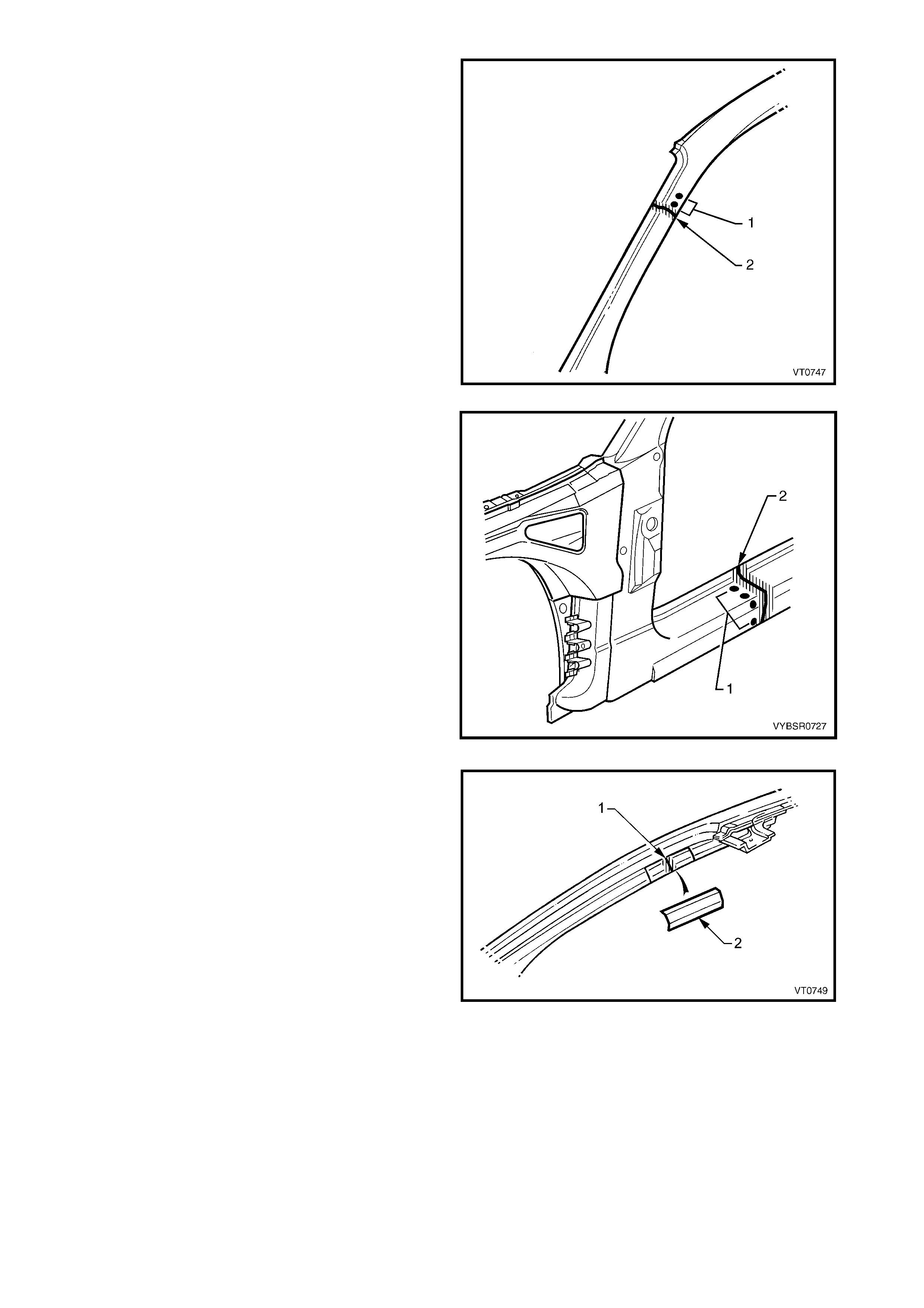
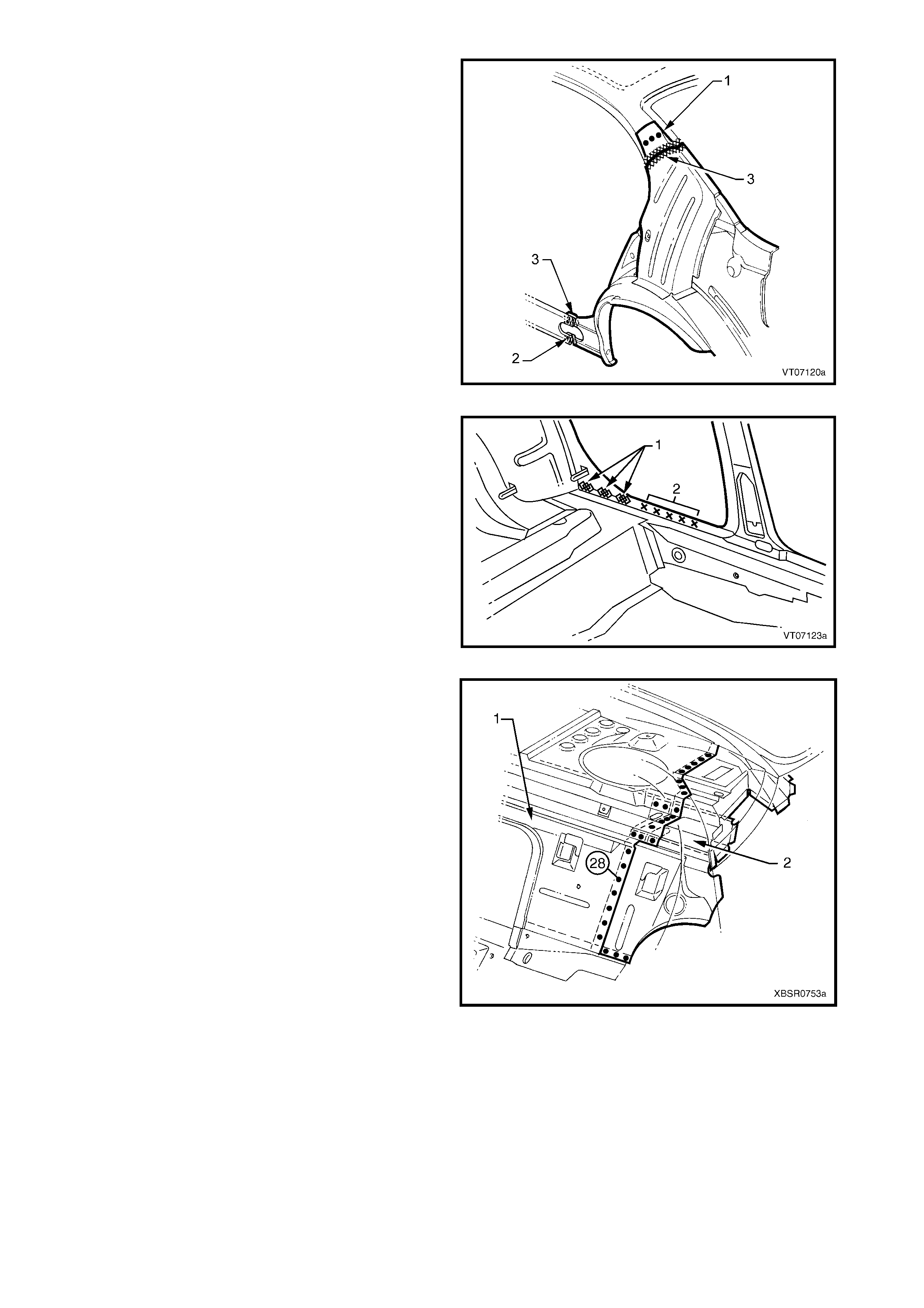
17. Spot weld (1) the hinge pillar section along the
door opening flange.
18. Spot weld (2) the flange beneath the rocker panel,
attaching the new panel to the inner rocker panel.
Figure 7A-70
19. Spot weld (1) the pillar along the windshield
opening flange.
Figure 7A-71
20. Spot or plug weld the door opening frame
assembly to the inner rocker panel and to the
hinge pillar inner panel ass embly. If the sheetmetal
was modified to allow access to these welds, it
should be repaired to its original configuration.
Figure 7A-72
21. Plug weld the inner rocker panel and hinge pillar
inner panel assembly to the rocker panel
reinforcement.
Figure 7A-73
22. Gaining access through the section of removed
inner rocker panel, MIG butt weld (1) the new
section of rocker panel reinforcement to the
existing section.
23. Replace the r em oved s ection of inner rock er panel
(2) by MIG butt welding it in place and spot welding
it along the door opening flange. Replace the spot
welds with the same number of as were cut out.
24. Dress the butt welds by grinding or sanding,
ensuring sufficient material remains to guarantee
the strength of the weld.
25. Install the door hinges, refer to 2.3 DOOR HINGE
(BODY SIDE) – REPLACE in Section 8.
26. Refinish and paint panels and other components
as required. Refer to Section 3, 1.3 PAINT
REFINISHING.
27. Apply Joint Sealer (Item 3) as required. Refer to
5. BODY SEALING, ADHESIVES & DEADENERS
in Section 3A.
Figure 7A-74
28. Apply Cavity W ax (Item 8) as required to the inside of any box sections or areas inac cessible to paint, ref er
to 6. CAVITY WAX in Section 3A.
29. Install the dash panel bolt through the hinge pillar and tighten to the specified torque.
30. Replace the windshield, refer to Section 1A6, STATIONARY GLASS in the MY 2003 VY & V2 Series II
Service Information.
31. Insert Cavity Foam into the hinge pillar as required, refer to Section 2, 10. CAVITY FOAM.
32. Install the rem aining components as described in the appropriate Sec tion of the MY 2003 VY & V2 Series II
Service Information.
DASH PANEL RETAINING BOLT
TORQUE SPECIFICATION 35.0 – 45.0 Nm
2.6 DOOR OPENING FRAME ASSEMBLY – PARTIAL REPLACE, CENTRE PILLAR
NOTE: Cavity Foam is used within the hinge, centre
and lock pillar cavities . Care is r equired when repairing
the vehicle in these areas, refer to Section 2,
10. CAVITY FOAM prior to beginning any work for
further information.
REMOVE
1. Remove the adjacent bolt-on panels and
components as described in the appropriate
Section of the MY 2003 VY & V2 Series II Service
Information.
2. Install the vehicle on a suitable fixture. As a
minimum, support the appropriate structural
sections of the vehicle on safety stands. Secure a
suitable tool between the front door opening
flanges to maintain alignment.
Figure 7A-75
3. Cut through the door opening frame assembly (1)
at the join of the rocker panel reinforcement and
centre pillar reinforcement (2).
NOTE: Make the cut carefully as the rocker panel
reinforcement must not be cut. The centre pillar
reinforcement is removed with the centre pillar section.
Figure 7A-76
4. Cut through the door opening frame assembly (1)
rearward of the dimple (2) in the flange.
NOTE: Make the cut carefully as the quarter panel
inner assembly must not be cut.
Figure 7A-77
5. Spot cut the welds attac hing the underbody jac king
locator (1) and remove.
6. Spot cut the welds on the flange attaching the
centre pillar section to the inner rocker panel (6).
Refer to weld group A.
7. Spot cut the welds on the underside of the rocker
panel attaching the centre pillar section to the
quarter panel inner assembly (7). Refer to weld
group B.
Figure 7A-78
8. Cut the door opening frame assembly (1) and
centre pillar reinforcement (2) at the intersection
point of the centre pillar upper reinforcement (3).
The intersection point can be seen by looking at
the side of the flange.
NOTE: Do not cut through the centre pillar inner
reinforcement assembly (4) or quarter panel inner
assembly (5).
Figure 7A-79
9. Spot c ut the welds on the door opening flanges on
both sides of the centre pillar and remove the
centre pillar section from the vehicle.
Figure 7A-80
10. From the remaining section of centre pillar,
carefully remove enough of the outer skin (1) to
expose the spot welds joining the overlapping
sections of centre pillar upper reinforcement (2)
and centre pillar reinforcement (3).
NOTE: Do not c ut the centre pillar inner reinf orcement
assembly (4) and quarter panel inner assembly (5).
Figure 7A-81
11. Spot cut as shown, to remove the remaining
tongue (1) of the c entre pillar reinforcement. Leave
the holes drilled in reinforcement to facilitate plug
welding the replacement section.
Figure 7A-82
REPLACE
NOTE 1: Spot welding is the preferred method for attaching of panels and should be used whenever possible.
Where the spot welding equipment will not access the required weld position, a plug weld should be performed.
NOTE 2: The same number and pos ition of s pot welds (or plug welds) s hould be used when replacing the panel,
as was used during manufacture, in order to maintain the original structural strength of the vehicle.
1. Cut the replacement panel through rocker section
as s hown. Ac curately m easure the position of c uts
to match the removed panel section.
Figure 7A-83
2. Cut the replacement panel at the top of the centre
pillar (1).
NOTE: Position the cut above the tongue on the c entre
pillar reinforcement, which is visible from the back of
the panel.
3. Adjust the cut on the vehicle side of the outer
panel so that it matches the cut on the
replacement section.
Figure 7A-84
4. On the replacement panel, cut along each side
and bend back the outer panel (3). This will
expose the spot welds attaching the remaining
piece of upper reinforcement (1) to the tongue (2)
of the centre pillar reinforcement.
Figure 7A-85
5. Spot c ut the nine welds and remove the rema ining
section of centre pillar upper reinforcement (1)
from the replacement panel.
Figure 7A-86
6. Cut two sections from s urplus r ock er panel pieces ,
or manufacture new sections (1), each
approximately 100 mm in length.
7. Prepare the mating surfaces and treat with Weld
Through Primer (Item 1) as required, refer to
5. BODY SEALING, ADHESIVES & DEADENERS
in Section 3A.
8. Clamp these sections firmly behind both the cut
faces of rocker panel on the vehicle and spot or
plug weld in place. Perform the welds at a
maximum spacing of 35 mm.
9. Mark the new panel with drilling locations in
preparation for plug welding where required. Drill
holes as marked.
10. Prepare all mating surfaces and treat with Weld
Through Primer (Item 1) as required, refer to
5. BODY SEALING, ADHESIVES & DEADENERS
in Section 3A.
Figure 7A-87
11. Install the replacement panel in position, sliding the
tongue of the centr e pillar reinf or c ement (1) behind
the centre pillar upper reinforcement (2).
NOTE: Manipulate the rock er panel section in position,
inserting the front first, then the rear.
12. Clamp the assembly in place and plug weld the
centre pillar upper reinforcement to the centre
pillar reinforcement at the upper join.
13. Plug weld the rocker panel section to the
reinforcement sections.
14. Spot weld along the door opening flanges on both
sides of the centre pillar.
Figure 7A-88
15. Fold the outer panel back in position at the top of
the centre pillar. Spot weld along the door flange
section and MIG butt weld the sections together as
shown.
16. MIG butt weld the joins in the rocker panel.
Figure 7A-89
17. Plug weld the flange attaching the centre pillar
section (1) to the inner rocker panel (2). Refer to
weld group A .
18. Plug weld on the underside of the roc ker panel the
centre pillar section to the quarter panel inner
assembly (3). Refer to weld group B.
19. Plug weld the underbody jacking locator (4) in
place.
20. Install the door hinges, refer to 2.3 DOOR HINGE
(BODY SIDE) – REPLACE in Section 8.
21. Dress the welds by grinding or sanding, ensuring
sufficient material remains to guarantee the
strength of the weld. Finish the area using an
appropriate technique.
22. Refinish and paint panels and other components
as required. Refer to Section 3, 1.3 PAINT
REFINISHING.
23. Apply Joint Sealer (Item 3) as required. Refer to
5. BODY SEALING, ADHESIVES & DEADENERS
in Section 3A.
24. Apply Cavity Wax ( Item 8) as requir ed to the inside
of any box sections or areas inaccessible to paint,
refer to 6. CAVITY WAX in Section 3A.
25. Insert Cavity Foam into the centre pillar as
required, refer to Section 2, 10. CAVITY FOAM.
26. Install the remaining components as described in
the appropriate Section of the MY 2003 VY & V2
Series II Service Information.
Figure 7A-90
2.7 DOOR OPENING FRAME ASSEMBLY – PARTIAL REPLACE, LOCK PILLAR
NOTE: Cavity Foam is used within the hinge, centre
and lock pillar cavities . Care is r equired when repairing
the vehicle in these areas, refer to Section 2,
10. CAVITY FOAM prior to beginning any work for
further information.
REMOVE
1. Remove the adjacent bolt-on panels and
components as described in the appropriate
Section of the MY 2003 VY & V2 Series II Service
Information.
2. Install the vehicle on a suitable fixture. As a
minimum, support the appropriate structural
sections of the vehicle on safety stands.
3. Remove the rear window assembly, refer to
Section 1A6, STATIONARY WINDOWS in the
MY 2003 VY & V2 Series II Service Information.
4. Remove rear quarter panel, refer to 2.1 REAR
QUARTER PANEL – REPLACE.
Figure 7A-91
5. Select a cut line (1) on the upper region of the lock
pillar within the region specified.
6. Carefully cut through the outer panel of the door
opening frame assembly only.
NOTE: In this area, the lock pillar reinforcement is
attached to the quarter panel inner assembly. Thus,
the outer panel of the door opening frame assembly
can be removed without affecting the reinforcement.
Figure 7A-92
7. Select a cutting position on the rocker panel
section of the door opening f rame ass embly within
the region specified (1). The cut r egion is between
the two dimples (2). Cut through the outer panel
only .
Figure 7A-93
8. Spot cut the welds on the flange around the rear
door opening, attaching the door opening frame
assembly to the quarter panel inner assembly.
Begin at the cut through the top of the pillar and
continue to the cut through the rocker panel
section.
Figure 7A-94
9. Spot cut the welds down the side of the rear
window opening, beginning at the point of the cut
through the lock pillar (1).
Figure 7A-95
10. Spot cut enough of the welds on the flange below
the roc k er panel, to detac h the door opening f r ame
assembly from the inner rocker panel.
Figure 7A-96
11. Spot cut enough of the welds below the rocker
panel, to detac h the door opening fram e assem bly
from the quarter panel inner assembly.
Figure 7A-97
12. Spot cut the welds around the wheelhouse
attaching the lock pillar section (1) to the quarter
panel inner assembly (2).
13. Remove the partial door opening frame assembly
from the vehicle, then repair any damage to
adjacent parts as required.
14. Check and rectify the alignment of the body as
required, refer to 3. BODY DIMENSIONS in
Section 3A.
Figure 7A-98
REPLACE
NOTE 1: Spot welding is the preferred method for attaching of panels and should be used whenever possible.
Where the spot welding equipment will not access the required weld position, a plug weld should be performed.
NOTE 2: The same number and pos ition of s pot welds (or plug welds) s hould be used when replacing the panel,
as was used during manufacture, in order to maintain the original structural strength of the vehicle.
1. Cut a replacement section from a new door opening frame assem bly, accurately measuring the position of
cuts to match the removed section.
2. Manufacture a reinforcement (1), approx. 100 mm
in length to match the inside of the lock pillar
section at the cut.
3. Prepare the mating surfaces and treat with Weld
Through Primer (Item 1) as required, refer to
5. BODY SEALING, ADHESIVES & DEADENERS
in Section 3A.
4. Clam p the section f irmly behind the c ut f ace of the
lock pillar on the vehicle and s pot or plug weld at a
maximum spacing of 35 mm.
Figure 7A-99
5. Using the same technique, manufacture or cut a
section of reinforcement panel (1), approx.
100 mm long, to fit the inside of the existing r ock er
panel at the point of the cut.
6. Prepare the mating surfaces and treat with Weld
Through Primer (Item 1) as required, refer to
5. BODY SEALING, ADHESIVES & DEADENERS
in Section 3A.
7. Clamp the manufactured reinforcement panel
firmly to the inside of the rocker panel on the
vehicle and plug weld in position. Position welds at
a maximum spacing of 35 mm.
8. Mark the new lock pillar panel with drilling locations
in preparation for plug welding. Drill holes as
required.
9. Prepare all mating surfaces and treat with Weld
Through Primer (Item 1) as required, refer to
5. BODY SEALING, ADHESIVES & DEADENERS
in Section 3A.
Figure 7A-100
10. Clamp the new lock pillar section in place on the
vehicle and check the door opening dimensions,
refer to 3. BODY DIMENSIONS in Section 3A.
11. Plug weld the replacement panel to the
manuf actured reinf orcem ent sections in the r ocker
panel area and at the top of the pillar.
12. MIG butt weld the joins in both these areas.
Figure 7A-101
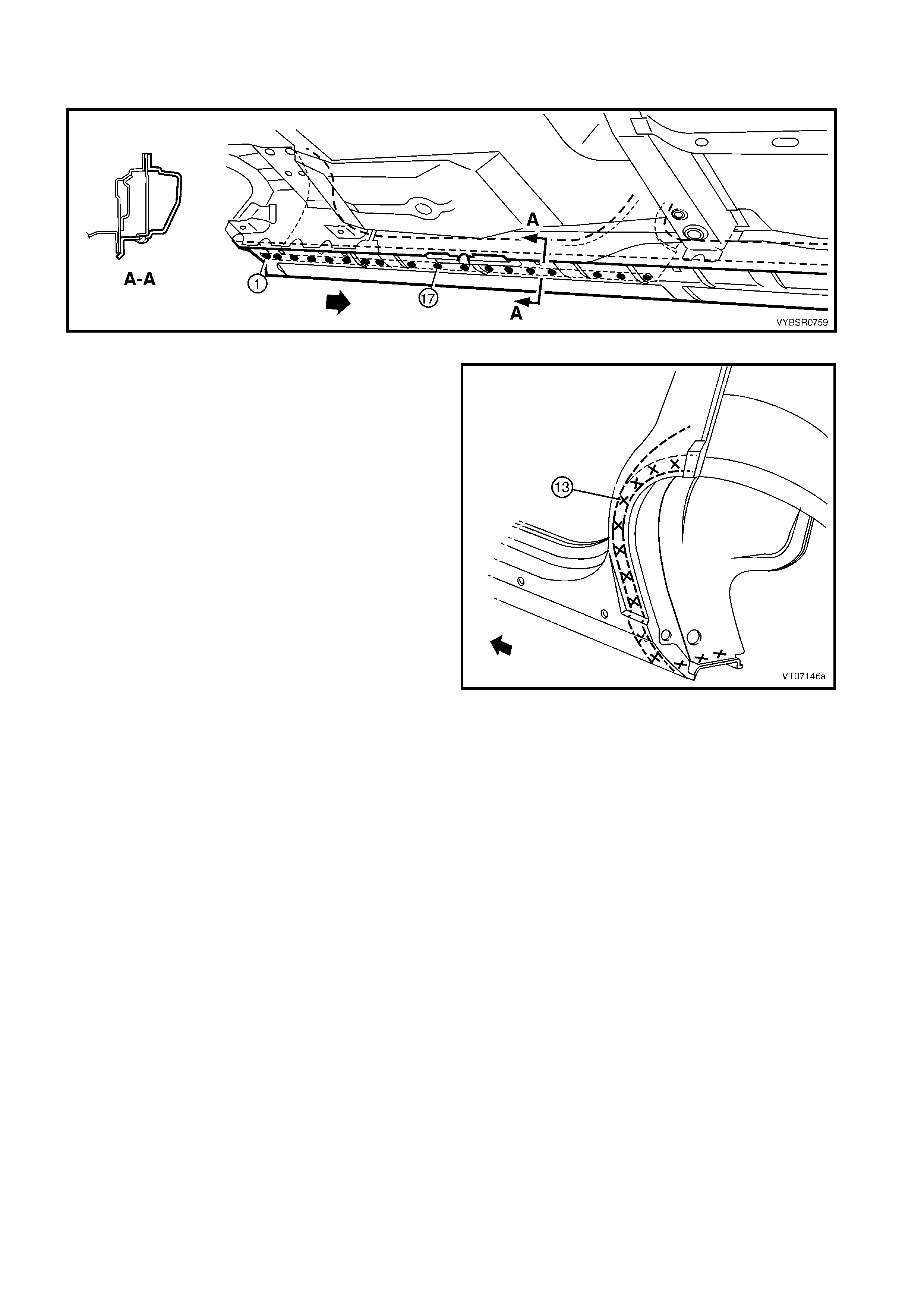
13. Spot weld along the flange around the rear door
opening, attaching the replacement section to the
quarter panel inner assembly.
Figure 7A-102
14. Spot weld down the side of the rear window
opening, attaching the replacement section to the
quarter panel inner assembly.
Figure 7A-103
15. Spot weld the flange below the rocker panel,
attaching the replacement section to the inner
rocker panel.
Figure 7A-104
16. Spot weld below the rocker panel, attaching the
replacement section to the quater panel inner
assembly.
Figure 7A-105
17. Spot weld around the wheelhouse to attach the
replacement s ec tion to the (1) to the quarter panel
inner assembly (2).
18. Replace rear quarter panel, refer to 2.1 REAR
QUARTER PANEL – REPLACE.
19. Refinish and paint panels and other components
as required. Refer to Section 3, 1.3 PAINT
REFINISHING.
20. Apply Joint Sealer (Item 3) as required. Refer to
5. BODY SEALING, ADHESIVES & DEADENERS
in Section 3A.
21. Apply Cavity Wax ( Item 8) as requir ed to the inside
of any box sections or areas inaccessible to paint,
refer to 6. CAVITY WAX in Section 3A.
22. Insert Cavity Foam into the lock pillar as required,
refer to Section 2, 10. CAVITY FOAM.
23. Install the remaining components as described in
the appropriate Section of the MY 2003 VY & V2
Series II Service Information.
Figure 7A-106
2.8 DOOR OPENING FRAME ASSEMBLY – PARTIAL REPLACE, ROCKER PANEL
IMPORTANT: This procedure details the replacement
of the rocker panel section of the door opening frame
assembly.
As there are several critical reinforcements in the lower
hinge pillar area, the rock er panel section must not be
cut forward of the area shown. If the rocker panel
is damaged forward of this area, replace the rocker
panel and partial hinge pillar as one section. Modify
this procedure accordingly, also referring to
2.5 DOOR OPENING FRAME ASSEMBLY –
PARTIAL REPLACE, HINGE PILLAR.
REMOVE
1. Remove the adjacent bolt-on panels and
components as described in the appropriate
Section of the MY 2003 VY & V2 Series II Service
Information.
2. Secure the vehicle on a suitable fixture. As a
minimum, support the appropriate structural
sections of the vehicle on safety stands. Install
suitable bracing in the vehicle to ensure that the
correct body alignment is maintained when the
rocker panel section is removed.
Figure 7A-107
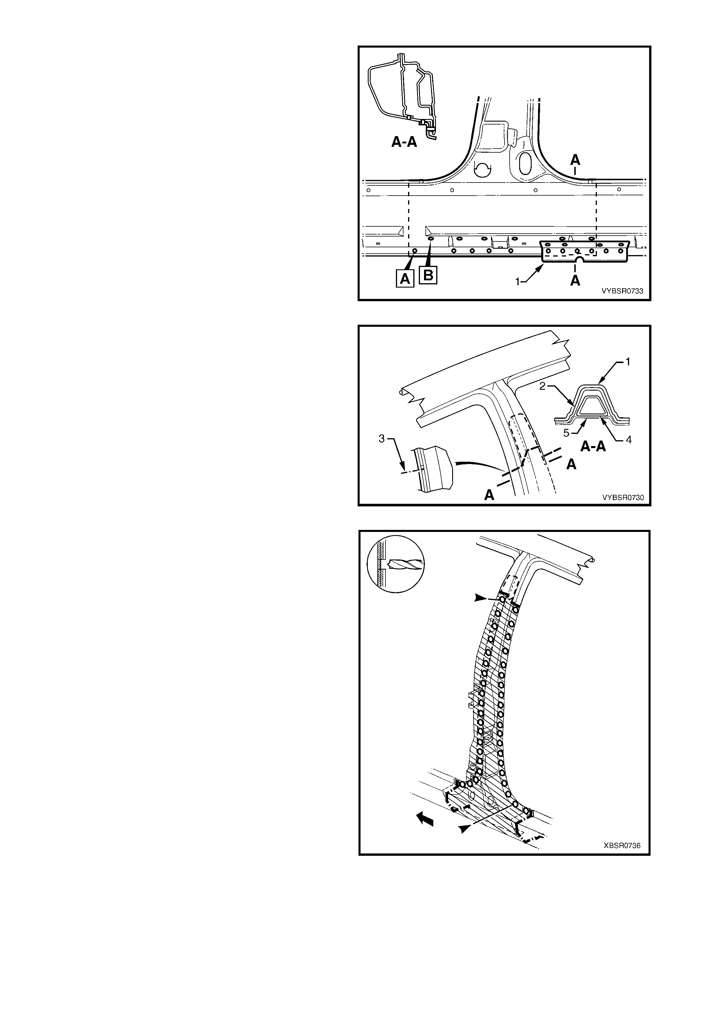
3. Cut through the rocker panel section of the door
opening frame assembly. The cut point (1) must
not be further forward than the third rocker panel
moulding attaching hole (2). Cut through both the
outer panel and the reinforcement.
Figure 7A-108
4. Using a s uitable cutting tool, c ut thr ough the centr e
pillar at a position 30 mm below the lower edge of
the door hinge. Cut through both the door opening
fram e ass embly (1) and centre pillar reinforc ement
(2).
Figure 7A-109
5. Cut through the lock pillar at a point between
120 mm - 220 mm above the top of the rocker
panel.
NOTE: There is no reinforcem ent panel in this area of
the vehicle.
Figure 7A-110
6. Spot cut the required number of welds, depending
on where the cut is made, to detach the rocker
panel section of the door opening fram e assembly
(1) from the quarter panel inner assembly (2).
7. Spot cut along the flange below the rocker panel
as required, to separate the rocker panel section
from the inner rocker panel and quarter panel inner
assembly. Refer to Figure 7A-112.
Figure 7A-111
Figure 7A-112
8. Spot cut the welds attaching the roc k er panel sec tion to the quarter panel inner as sem bly as required. Refe r
to Figure 7A-113.
Figure 7A-113
9. Spot cut the welds along the lower edge of the
front and rear door openings as required, to
complete the detachment of the rocker panel
section.
10. Remove the panel from the vehicle, then repair
any damage to adjacent parts.
11. Check and rectify the alignment of the body as
required, refer to 3. BODY DIMENSIONS in
Section 3A.
Figure 7A-114
REPLACE
NOTE 1: Spot welding is the preferred method for attaching of panels and should be used whenever possible.
Where the spot welding equipment will not access the required weld position, a plug weld should be performed.
NOTE 2: The same number and pos ition of s pot welds (or plug welds) s hould be used when replacing the panel,
as was used during manufacture, in order to maintain the original structural strength of the vehicle.
Cut a new replacement rocker panel section. Accurately measure the position of the cuts on the removed
section.
1. Remove a section of inner rocker panel (1), cut
50 mm each side of the cut in the rocker panel.
This allows access for welding the rocker panel
reinforcement.
Figure 7A-115
2. Manufacture or cut a reinforcement (1)
(approxim ately 100 m m long) to f it on the inside of
the existing rocker panel at the point of the cut.
3. Prepare the mating surfaces and treat with Weld
Through Primer (Item 1) as required, refer to
5. BODY SEALING, ADHESIVES & DEADENERS
in Section 3A.
4. Clamp the manufactured reinforcement firmly to
the inside of the rocker panel section of the door
opening frame assembly on the vehicle and plug
weld in position. Position welds at a maximum
spacing of 35 mm.
Figure 7A-116
5. Manufacture or cut a reinforcement (1)
(approximately 100 mm long) to fit inside of the
existing centre pillar section at the point of the cut.
6. Prepare the mating surfaces and treat with Weld
Through Primer (Item 1) as required, refer to
5. BODY SEALING, ADHESIVES & DEADENERS
in Section 3A.
7. Clamp the manufactured reinforcement panel
firmly to the inside of the outer panel of the door
opening frame assembly on the vehicle and plug
weld in position. Position welds at a maximum
spacing of 35 mm.
8. Repeat steps 6, 7 & 8 and install a reinforcement
at the rear rocker panel / lock pillar lower cut as
required.
9. Mark the replacement rocker panel section with
drilling positions in preparation for plug welding as
required.
NOTE: The outer panel will be plug welded from the
outer side of the vehicle, while the rocker panel and
centre pillar reinforcements will be butt welded from
the inner side of the vehicle.
10. Prepare all mating surfaces and treat with Weld
Through Primer (Item 1) as required, refer to
5. BODY SEALING, ADHESIVES & DEADENERS
in Section 3A.
Figure 7A-117
11. Install the replacement section onto the vehicle by
sliding the front and centre pillar sections onto the
reinforcements, while lifting the rear into position.
12. Clamp the panel in position.
13. Weld the new section to the centre pillar by plug
welding (1).
14. MIG butt weld the centre pillar reinforcement from
inside the centre pillar, through the large hole in
the inner panel immediately behind the weld.
15. Finish the centre pillar attachment by MIG
welding (2) along the join of the outer panel.
Figure 7A-118
16. Plug weld (1) the replacement section at the front
join, then MIG butt weld (2) the two sections
together.
Figure 7A-119
17. Gaining access through the section of removed
floor side panel, MIG butt weld (1) the new s ection
of rocker panel reinforcement to the existing
section.
18. Replace the removed section of floor side
panel (2) by MIG butt welding it in place and spot
welding it along the door opening flange. Replace
the spot welds with the same number as were
removed.
Figure 7A-120
19. Plug weld the rear join as required.
20. MIG butt weld the joint line between the panels.
Figure 7A-121
21. Spot or plug weld the flanges of the front and rear
door openings as required.
NOTE: Us e the same number and pos ition of welds as
removed during removal.
22. Spot or plug weld the door opening frame along
the flange below the rocker panel as required,
refer to Figure 7A-123.
Figure 7A-122
Figure 7A-123
23. Plug weld up through the rocker panel to attach the replacement section to the quarter panel inner assembly.
Refer to Figure 7A-124.
Figure 7A-124
24. If required, spot weld the replacement section to
the quarter panel inner assembly around the rear
wheel arch as shown.
25. Refinish and paint panels and other components
as required. Refer to Section 3, 1.3 PAINT
REFINISHING.
26. Apply Joint Sealer (Item 3) as required. Refer to
5. BODY SEALING, ADHESIVES & DEAD ENERS
in Section 3A.
27. Apply Cavity Wax ( Item 8) as requir ed to the inside
of any box sections or areas inaccessible to paint,
refer to 6. CAVITY WAX in Section 3A.
28. Install the remaining components as described in
the appropriate Section of the MY 2003 VY & V2
Series II Service Information.
Figure 7A-125
2.9 FENDER LOWER REAR BRACKET – REPLACE
The fender lower rear bracket (1) is spot welded at four
places to the door opening frame assembly.
Clamp the f ender lower rear brack et pos ition as shown
prior to plug welding and check the alignment of the
fender to the body and front door.
Refinish and paint panels and other components as
required. Refer to Section 3, 1.3 PAINT
REFINISHING.
Apply Cavity W ax (Item 8) as required to the inside of
any box sections or areas inaccessible to paint, refer to
6. CAVITY WAX in Section 3A.
Figure 7A-126
2.10 HINGE PILLAR INNER PANEL ASSEMBLY – REPLACE
REMOVE
1. Remove the adjacent bolt-on panels and
components as described in the appropriate
Section of the MY 2003 VY & V2 Series II Service
Information.
2. Remove the door opening frame assembly, refer
to 2.4 DOOR OPENING FRAME ASSEMBLY –
REPLACE, or remove the hinge pillar section of
the door opening frame assembly, refer to
2.5 DOOR OPENING FRAME ASSEMBLY –
PARTIAL REPLACE, HINGE PILLAR.
3. If required, rem ove the dash panel assem bly, ref er
to Section 5 COCKPIT MODULE in this
Supplement.
NOTE: If the cockpit module is not damaged an
alternative is provided in this procedure.
4. Add bracing as required to maintain the alignment
of the vehicle structure.
Figure 7A-127
5. Grind the MIG welds (1) attaching the hinge pillar
inner panel assembly to the inner rocker panel.
Figure 7A-128
6. Spot cut the welds attaching the hinge pillar inner
panel assembly to the roof front header and
quarter panel inner extension.
NOTE: Structural adhesive is applied to join (1). If the
roof panel has not been r emoved, it will be very diff ic ult
to remove the panel. As an alternative:
- If only the lower section is dam aged, detach the
hinge pillar inner upper panel (1) from the hinge
pillar inner lower panel (2) and replace the lower
panel, or
- Cut the hinge pillar inner panel assembly (3)
approximately 50 mm from the top of the
windscreen aperture. If a partial replacement of
the door opening frame assembly is being
performed, this point is 50 mm above the cut in
the outer panels (4). Refer to Figure 7A-130.
Figure 7A-129
Figure 7A-130
7. Spot cut the welds attaching the hinge pillar inner
panel assem bly to the f ront wheelhouse panel and
front floor panel extension, refer to weld group A.
8. If the dash panel assem bly was not removed, spot
cut the eight welds attaching the adhesive
channels to the hinge pillar inner panel assembly,
refer to weld group B.
9. If required, remove any remaining spot welds
where the wheelhouse panel upper side rail
attached the front wheelhouse panel and hinge
pillar inner panel assembly .
10. Cut the adhesive between the dash panel
assembly and hinge pillar inner panel assembly.
11. Remove the hinge pillar inner panel as s embly from
the vehicle and as required, clean off any
remaining adhesive and ensure the adhesive
channels are removed.
12. Repair any damage to adjacent parts as required.
Figure 7A-131
REPLACE
NOTE 1: Spot welding is the preferred method for attaching of panels and should be used whenever possible.
Where the spot welding equipment will not access the required weld position, a plug weld should be performed.
NOTE 2: The same number and pos ition of s pot welds (or plug welds) s hould be used when replacing the panel,
as was used during manufacture, in order to maintain the original structural strength of the vehicle.
1. If an alternate removal method was used, referring to Figure 7A-130, either:
- Cut the replacement section to match the cut at the top of the hinge pillar, or
- Spot cut the welds attaching the hinge pillar inner upper panel to the hinge pillar inner lower panel.
2. Mark the new panel and drill holes in preparation for plug welding where required.
3. Prepare all mating surfaces and treat with Weld Through Primer (Item 1) as required, refer to
5. BODY SEALING, ADHESIVES & DEADENERS in Section 3A.
4. If the dash panel assembly was removed, it will be installed later, proceed to Step 7.
5. If the dash panel assembly was NOT removed, prepare the adhesive channels on the replacement section
and the dash panel assembly, refer to Section 5 COCKPIT MODULE.
6. Mix the dash panel silicone adhesive refer to Section 5 COCKPIT MODULE. Apply the adhesive to fill the
adhesive channels on the replacement section.
NOTE: Only the correct material described in Section 5 COCKPIT MODULE is to be used.
7. If the full hinge pillar inner panel assembly is being replaced, apply structural adhesive (Item 6) to the
mating surfaces of the hinge pillar inner panel assembly and quarter panel inner extension, refer to
5. BODY SEALING, ADHESIVES & DEADENERS in Section 3A.
8. Install and clamp the new panel in position on the
vehicle.
NOTE: If the dash panel assembly was not removed,
place the hinge pillar inner panel assembly (1) slightly
lower and slide it upwards ensuring the dash panel
flange (2) seats into the adhesive channel.
9. Temporarily install the dash panel attaching bolts
through the hinge pillar inner panel assembly and
within the plenum chamber.
10. Finish the application of the dash panel adhesive,
refer to Section 5 COCKPIT MODULE.
Figure 7A-132
11. If the full hinge pillar inner panel assembly was
removed, spot or plug weld the hinge pillar inner
panel assembly to the roof front header and
quarter panel inner extension.
NOTE: Ensure the structural adhesive Item 6, is
applied to the join (1) refer to 5. BODY SEALING,
ADHESIVES & DEADENERS in Section 3A.
12. If only the lower s ection was rem oved, spot or plug
weld the hinge pillar inner upper panel (1) to the
hinge pillar inner lower panel (2), refer to Figure
7A-134.
13. If the pillar was cut near the top of the windscreen
aperture, either MIG butt weld the join (3) if the full
door opening frame assembly was removed, or
make two tack welds to secure it until the door
opening frame assembly hinge pillar section is
installed, also refer to Figure 7A-134.
NOTE: This join forms the top access cut point
for joining of the reinforcement as described in
2.5 DOOR OPENING FRAME ASSEMBLY –
PARTIAL REPLACE, HINGE PILLAR.
Figure 7A-133
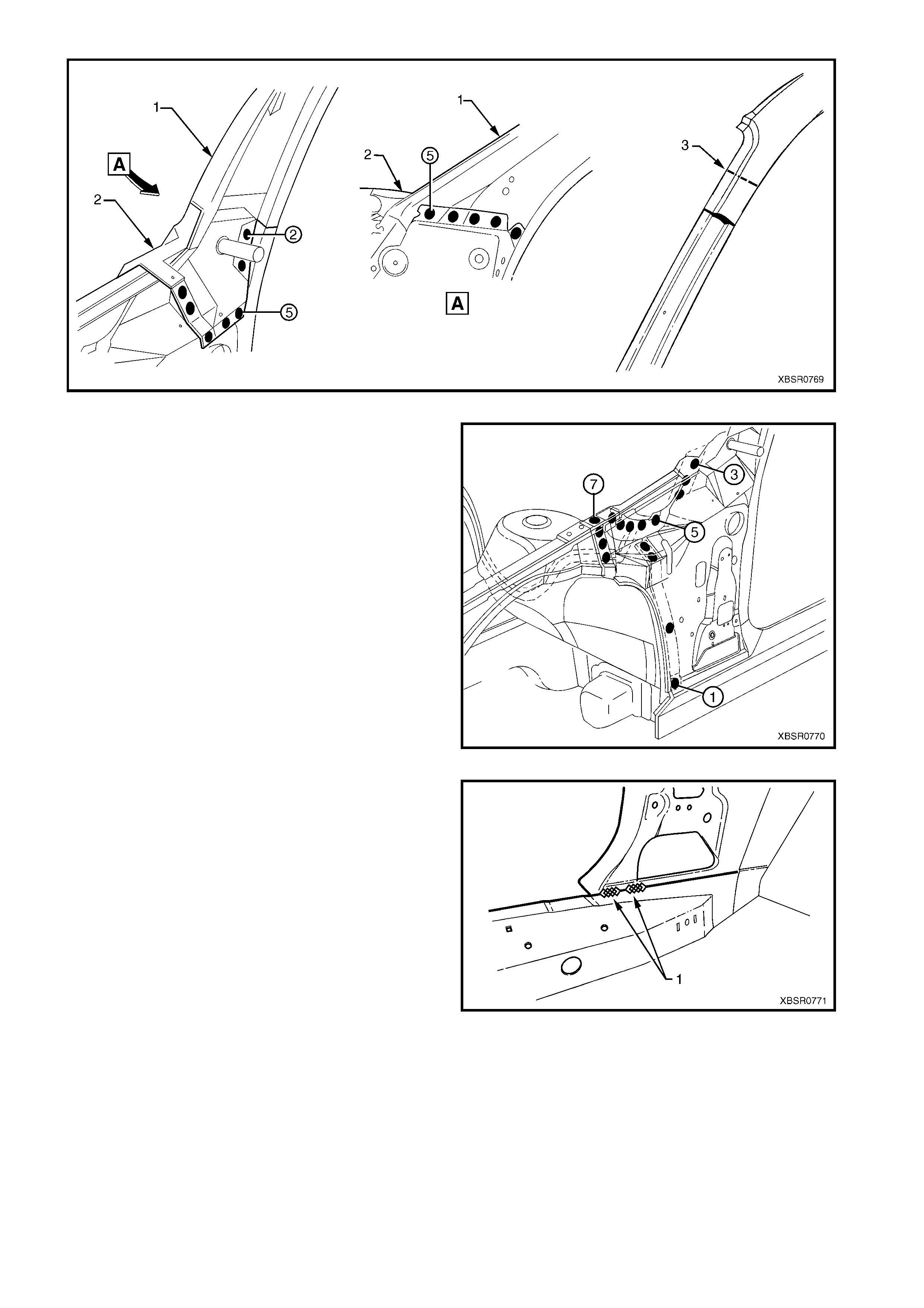
Figure 7A-134
14. Spot or plug weld the hinge pillar inner panel
assembly to the front wheelhouse panel and front
floor extension.
Figure 7A-135
15. MIG weld two places (1) across the inner rocker
panel and hinge pillar inner panel assembly.
16. Replac e the door opening f rame assembly, refer to
2.4 DOOR OPENING FRAME ASSEMBLY –
REPLACE or the hinge pillar section of the
door opening frame assembly, refer to
2.5 DOOR OPENING FRAME ASSEMBLY –
PARTIAL REPLACE, HINGE PILLAR.
17. Refinish and paint panels and other components
as required. Refer to Section 3, 1.3 PAINT
REFINISHING.
18. Apply Joint Sealer (Item 3) as required. Refer to
5. BODY SEALING, ADHESIVES & DEADENERS
in Section 3A.
19. Apply Cavity Wax ( Item 8) as requir ed to the inside
of any box sections or areas inaccessible to paint,
refer to 6. CAVITY WAX in Section 3A.
20. Install the remaining components as described in
the appropriate Section of the MY 2003 VY & V2
Series II Service Information.
Figure 7A-136
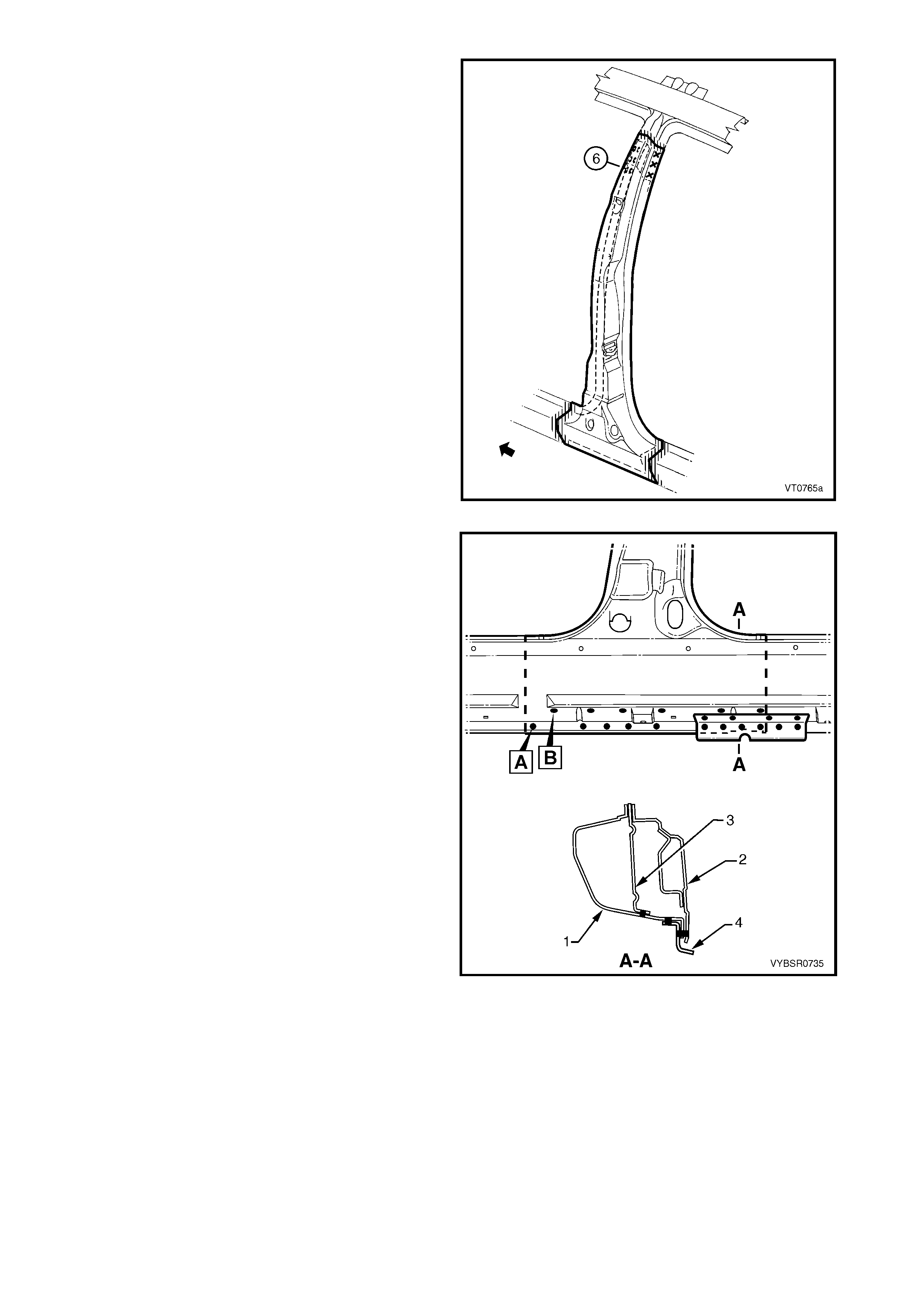
2.11 QUARTER PANEL INNER ASSEMBLY – REPLACE
REMOVE
1. Remove the adjacent bolt-on panels and
components as described in the appropriate
Section of the MY 2003 VY & V2 Series II Service
Information.
2. Mount the vehicle on a suitable jig to maintain
correct body alignment when the quarter panel
inner assembly is removed.
3. Remove rear quarter panel, refer to 2.1 REAR
QUARTER PANEL – REPLACE.
4. Remove the roof panel, and partially remove the
roof bow panel and roof rear panel, refer to
Section 9 ROOF.
5. Remove the door opening frame assembly, refer
to 2.4 DOOR OPENING FRAME ASSEMBLY –
REPLACE.
6. Add further bracing tools as required, to maintain
the alignment of the vehicle structure.
Figure 7A-137
7. Cut any remaining spot welds and grind the MIG
welds (1), attaching the quarter panel inner
assembly to the inner rocker panel.
8. Spot cut the welds attaching the rear wheelhouse
inner to the rear floor panel assembly, refer to
Figure 7A-139.
Figure 7A-138
Figure 7A-139
9. Spot cut the welds attac hing the rear window panel
assembly (1) to the rear seat back extension
assembly (2).
Figure 7A-140
10. As required, spot cut the welds attaching the rear
seat back extension assembly (1) to the rear
window panel assembly (2).
NOTE 1: Structural adhesive (Item 6) is applied in the
areas shown shaded. As this material is extremely
strong, the rear seat back extension assembly may
require removing with a grinder.
NOTE 2: Remove the remaining flange of the rear
quarter panel, leaving only the rear window panel
assembly.
Figure 7A-141
11. The quarter panel inner extension (1) is attached
to the hinge pillar inner panel assembly with spot
welds and structural adhesive (2) (Item 6, refer to
5. BODY SEALING, ADHESIVES & DEADENERS
in Section 3A). As the adhesive is extremely
strong, cut through the quarter panel inner
extension just behind the join and remove the
remaining joint piece with a grinder.
NOTE: As an alternative, remove the spot welds from
the join (3), leaving the quarter panel inner extension
intact.
12. Remove the quar ter panel inner assembly from the
vehicle, then repair any damage to adjacent parts
as required.
13. Check and rectify the alignment of the body as
required, refer to 3. BODY DIMENSIONS in
Section 3A.
Figure 7A-142
REPLACE
NOTE 1: Spot welding is the preferred method for attaching of panels and should be used whenever possible.
Where the spot welding equipment will not access the required weld position, a plug weld should be performed.
NOTE 2: The same number and pos ition of s pot welds (or plug welds) s hould be used when replacing the panel,
as was used during manufacture, in order to maintain the original structural strength of the vehicle.
1. Mark the new panel and drill holes in preparation for plug welding where required.
2. Prepare all mating surfaces and treat with Weld Through Primer (Item 1) as required, refer to
5. BODY SEALING, ADHESIVES & DEADENERS in Section 3A.
3. Either, apply structural adhesive (Item 6, refer to
5. BODY SEALING, ADHESIVES & DEADENERS
in Section 3A) to the mating surfaces of the
quarter panel inner ex tens ion and hinge pillar inner
panel assem bly (1) , if this joint was cut or, rem ove
the quarter panel inner extension from the
replacement section.
4. Clamp the new panel in position on the vehicle.
5. Depending on removal method either:
- Spot weld the quarter panel inner extension
and hinge pillar inner panel assembly join (1),
or
- Spot weld the quarter panel inner assembly to
the quarter panel inner extension (2).
Figure 7A-143
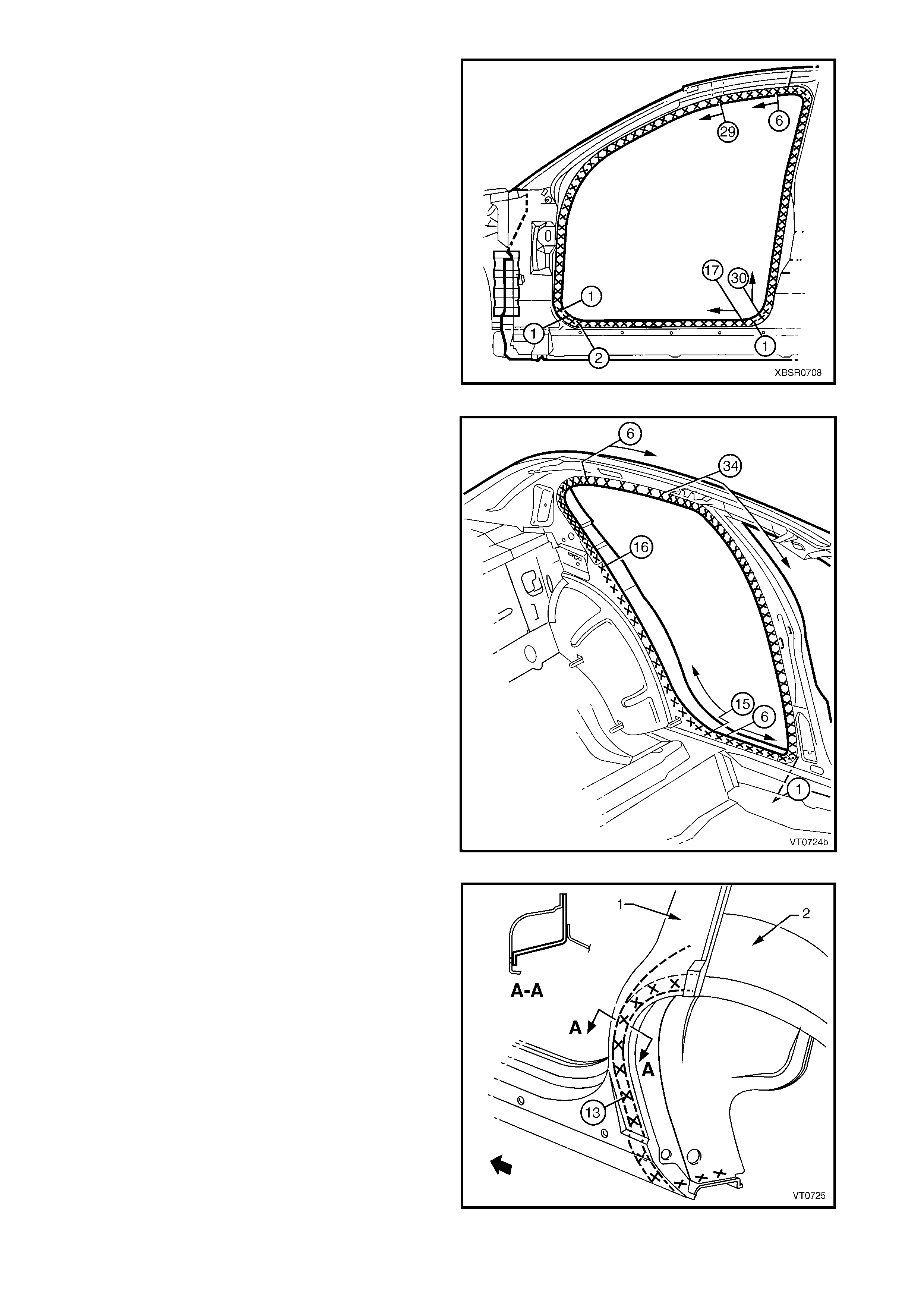
6. Spot weld the quarter panel inner assembly to the
inner rocker panel.
NOTE: Only make several spot welds in the door
opening flanges as they will be fully welded when the
door opening frame assembly is fitted.
7. MIG weld the base of the centre pillar (1) and the
series of three MIG welds at the base of the lock
pillar.
NOTE: Each MIG weld to be 25 mm long.
Figure 7A-144
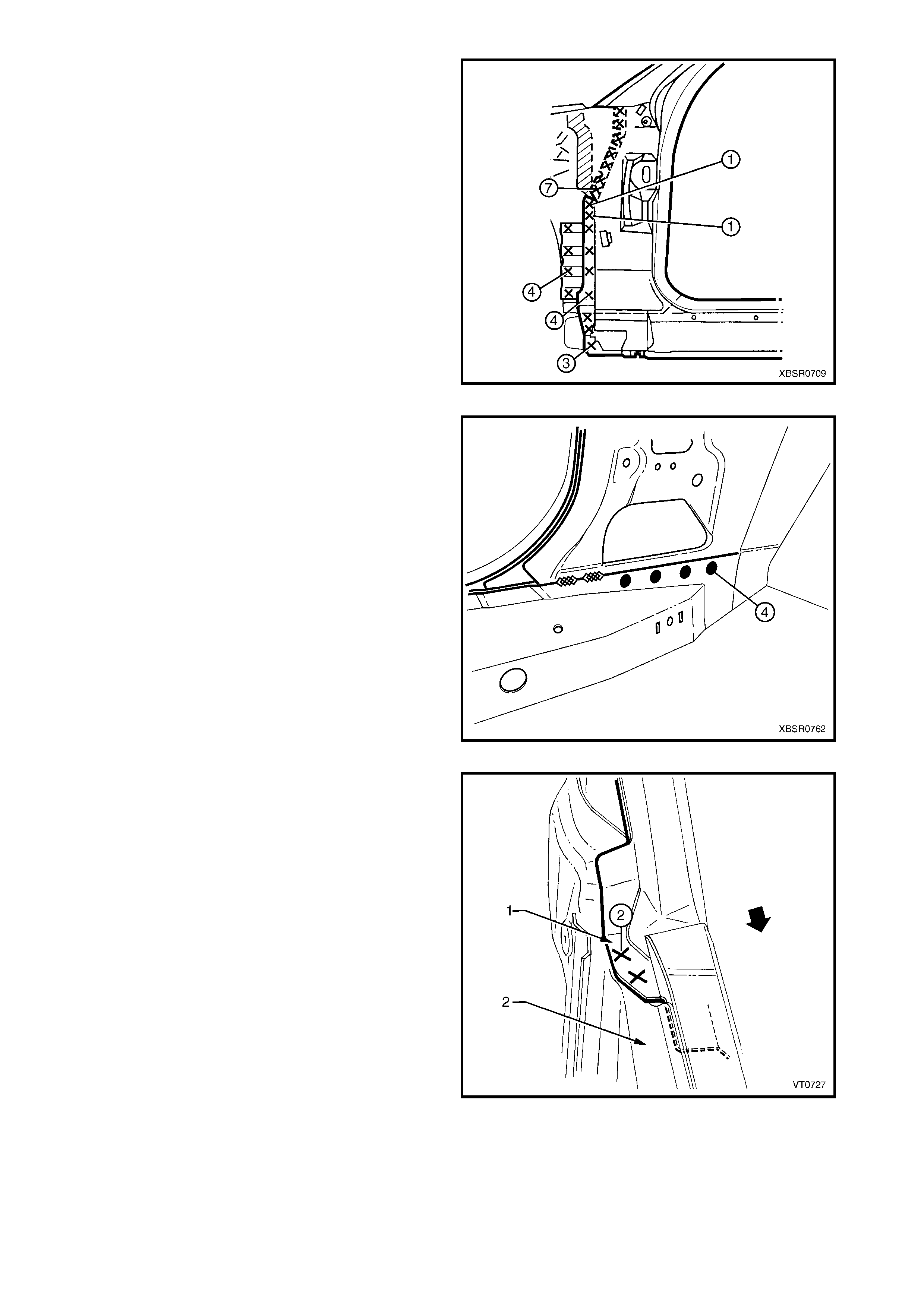
8. Plug weld the rear window panel assembly (1) to
the rear seat back extension assembly (2).
9. Spot weld the rear wheelhouse inner (1) to the rear
floor panel assembly, refer to Figure 7A-146.
Figure 7A-145

Figure 7A-146
10. Clean up welds as required and prime any bare metal.
11. Install the door opening frame assembly, refer to 2.4 DOOR OPENING FRAME ASSEMBLY – REPLACE.
12. Replace the roof and roof support panels, as described in Section 9 ROOF in this Supplement.
13. Prepare the rear quarter panel for installation, refer to 2.1 REAR QUARTER PANEL – REPLA CE.
IMPORTANT: Do not modify the rear quarter panel flange at the base of the lock pillar as stated in the rear
quarter panel replacement procedure, as the flange is required for this procedure.
14. Using a lever , gently prise down the rear seat back
extension assembly sufficiently to allow structural
adhesive (Item 6, refer to 5. BODY SEALING,
ADHESIVES & DEADENERS in Section 3A) to be
inserted into the mating flange as shown (2).
Figure 7A-147
15. Apply structural adhesive (Item 6, refer to
5. BODY SEALING, ADHESIVES & DEAD ENERS
in Section 3A) to the rear quarter panel flange as
shown (1).
16. Fit and clamp the rear quarter panel into position,
refer to 2.1 REAR QUARTER PANEL –
REPLACE.
NOTE: Ensure the rear quarter panel flange (1) is
fitted between the quarter panel inner assembly and
rear window panel assembly. If required prise up the
rear window panel to provide clearance.
Figure 7A-148

17. Spot or plug weld through the rear window panel
assembly (1), rear seat back extension assembly
(2) and rear quarter panel (3) as shown.
18. Finish installing the rear quarter panel, refer to
2.1 REAR QUARTER PANEL – REPLACE.
19. Refinish and paint panels and other components
as required. Refer to Section 3, 1.3 PAINT
REFINISHING.
20. Apply Joint Sealer (Item 3) as required. Refer to
5. BODY SEALING, ADHESIVES & DEADENERS
in Section 3A.
21. Apply Cavity Wax ( Item 8) as requir ed to the inside
of any box sections or areas inaccessible to paint,
refer to 6. CAVITY WAX in Section 3A.
22. Apply spray-on deadener to the wheel side of the
wheelhouse, refer to 5. BODY SEALING,
ADHESIVES & DEADENERS in Section 3A.
23. Install the remaining components as described in
the appropriate Section of the MY 2003 VY & V2
Series II Service Information.
Figure 7A-149
2.12 QUARTER PANEL INNER ASSEMBLY – PARTIAL REPLACE
REMOVE
1. Remove the adjacent bolt-on panels and
components as described in the appropriate
Section of the MY 2003 VY & V2 Series II Service
Information.
2. If required, m ount the vehicle on a suitable fixture.
Secure a suitable tool between the rear door
opening flanges to maintain alignment once the
sections are removed.
3. Remove rear quarter panel, refer to 2.1 REAR
QUARTER PANEL – REPLACE.
4. Remove lock pillar section of the door opening
frame assembly, refer to 2.7 DOOR OPENING
FRAME ASSEMBLY – PARTIAL REPLACE,
LOCK PILLAR.
Figure 7A-150
5. Carefully cut through the quarter panel inner
assembly at the rocker panel region.
NOTE: The position of the cut (1) should be a
minimum of 50 mm shorter than that of the outer
panel (2) to allow sufficient access for rejoining.
Figure 7A-151
6. Grind off the MIG welds (1) and cut enough spot
welds (2) to detach the quarter panel inner
assembly section from the inner rocker panel.
7. Spot cut the welds attaching the rear wheelhouse
inner (1) to the rear floor panel assembly, refer to
Figure 7A-153.
Figure 7A-152
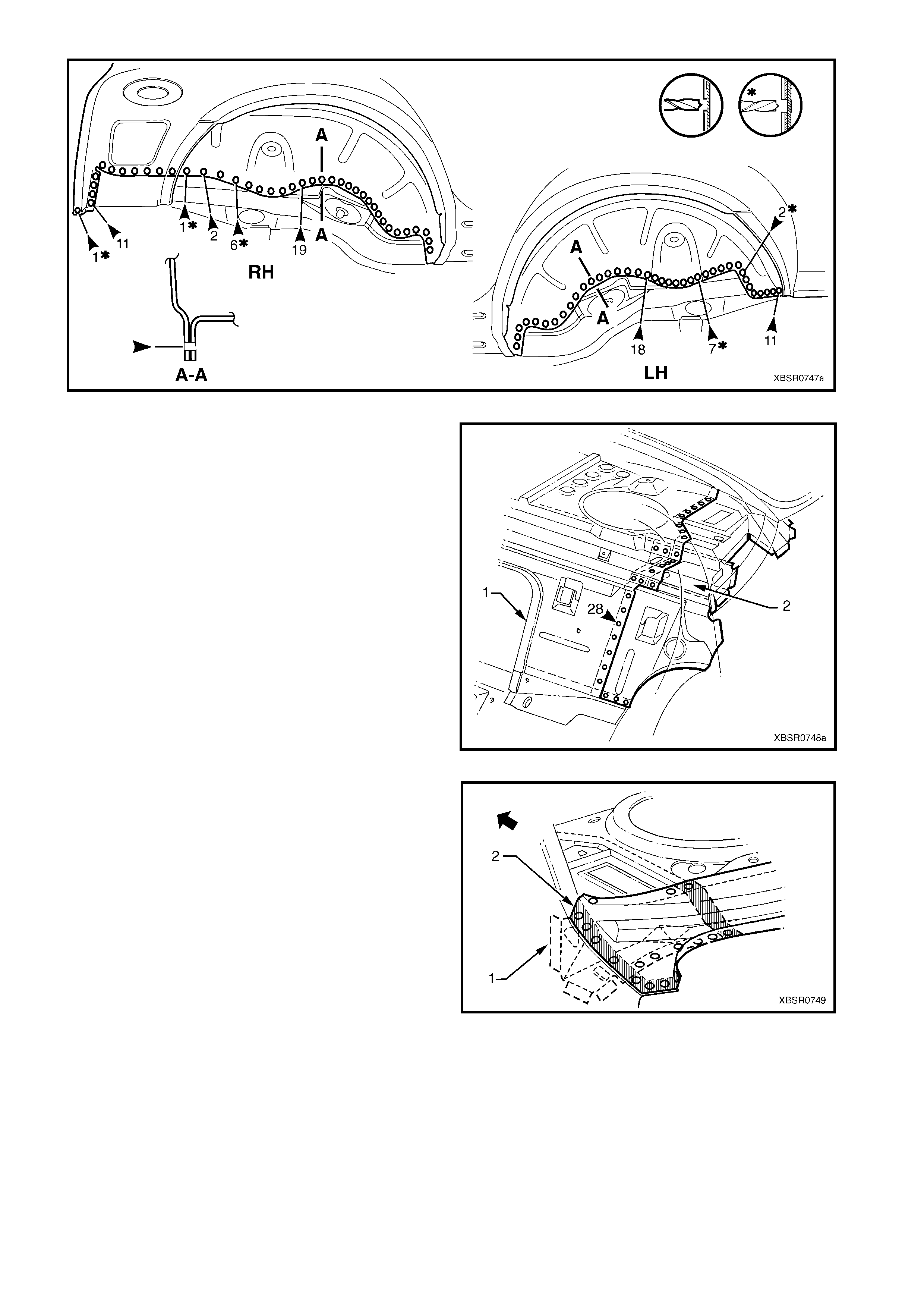
Figure 7A-153
8. Spot cut the welds attac hing the rear window panel
assembly (1) to the rear seat back extension
assembly (2).
Figure 7A-154
9. As required, spot cut the welds attaching the rear
seat back extension assembly (1) to the rear
window panel assembly (2).
NOTE 1: Structural adhesive (Item 6) is applied in the
areas shown shaded. As this material is extremely
strong, the rear seat back extension assembly may
require removing with a grinder.
NOTE 2: Remove the remaining flange of the rear
quarter panel, leaving only the rear window panel
assembly.
Figure 7A-155
10. Cut through the lock pillar reinforcement panel (1)
and quarter panel inner assembly at a point 50 mm
below the cut through the lock pillar section of the
door opening frame assembly (2).
11. Remove the partial quarter panel inner assembly
from the vehicle, then repair any damage to
adjacent parts.
12. Check and rectify the alignment of the body as
required, refer to 3. BODY DIMENSIONS in
Section 3A.
Figure 7A-156
REPLACE
NOTE 1: Spot welding is the preferred method for attaching of panels and should be used whenever possible.
Where the spot welding equipment will not access the required weld position, a plug weld should be performed.
NOTE 2: The same number and pos ition of s pot welds (or plug welds) s hould be used when replacing the panel,
as was used during manufacture, in order to maintain the original structural strength of the vehicle.
1. Accurately cut a replacem ent inner lock pillar sect ion from a new panel assem bly. T he new panel should be
cut 40 mm longer at the mating faces to allow for overlap.
2. Remove the flange from the overlap section and
form a j oggle (1) at the top end of the new panel to
facilitate a lap joint. Both the inner panel and
reinforcement panel should be joggled.
NOTE: Accurately measure the required length of
joggle to match the overlap. This should be slightly in
excess of 40 mm.
Figure 7A-157
3. Remove the f lange f r om the overlap ar ea and f orm
a joggle (1) in the rocker panel area of the new
panel to allow for a lap joint in this area.
NOTE: Accurately measure the required length of
joggle to match the overlap. This should be slightly in
excess of 40 mm.
4. Mark the new panel and the existing panels with
drilling locations in preparation for plug welding
where required. Drill holes as marked.
5. Prepare all mating surfaces and treat with Weld
Through Primer (Item 1) as required, refer to
5. BODY SEALING, ADHESIVES & DEADENERS
in Section 3A.
6. Position the new panel on the vehicle and clamp in
place.
Figure 7A-158
7. Plug weld the lap joints at the top of the lock
pillar (1) and in the rocker panel area (2).
8. Finish the joints by MIG welding (3).
Figure 7A-159
9. MIG weld (1) in three places (each 25 mm long)
and spot weld (2) as required to attach the quarter
panel inner assembly to the inner rocker panel.
Figure 7A-160
10. Plug weld the rear window panel assembly (1) to
the rear seat back extension assembly (2).
11. Spot weld the rear wheelhouse inner (1) to the rear
floor panel assembly, refer to Figure 7A-162.
Figure 7A-161
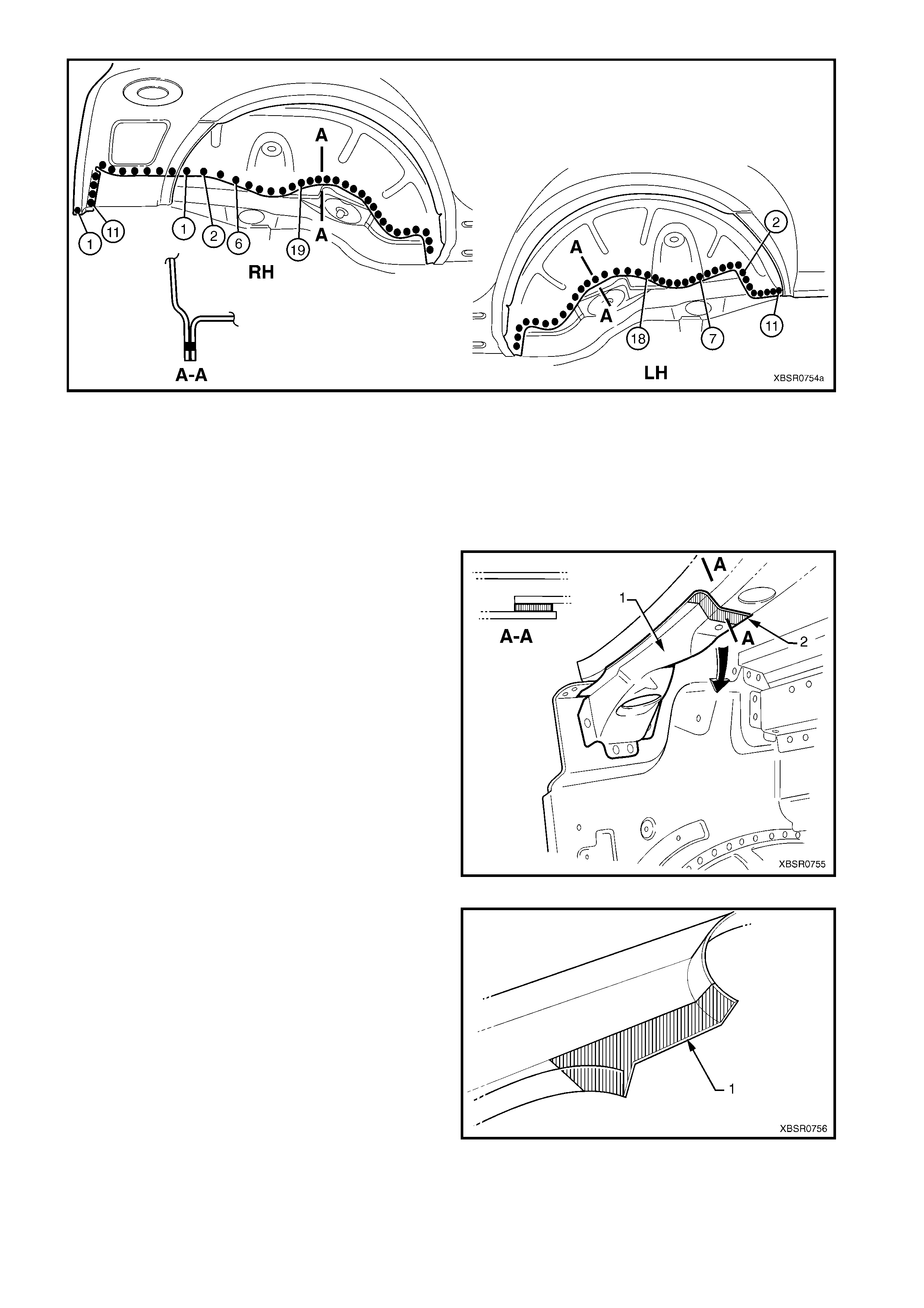
Figure 7A-162
12. Clean up welds as required and prime any bare metal.
13. Replace the partial lock pillar section of the door opening frame assembly. Refer to 2.7 DOOR OPENING
FRAME ASSEMBLY – PARTIAL REPLACE, LOCK PILLAR.
14. Prepare the rear quarter panel for installation, refer to 2.1 REAR QUARTER PANEL – REPLA CE.
IMPORTANT: Do not modify the rear quarter panel flange at the base of the lock pillar as stated in the rear
quarter panel replacement procedure, as the flange is required for this procedure.
15. Using a lever , gently prise down the rear seat back
extension assembly sufficiently to allow structural
adhesive (Item 6, refer to 5. BODY SEALING,
ADHESIVES & DEADENERS in Section 3A) to be
inserted into the mating flange as shown (2).
Figure 7A-163
16. Apply structural adhesive (Item 6, refer to
5. BODY SEALING, ADHESIVES & DEAD ENERS
in Section 3A) to the rear quarter panel flange as
shown (1).
17. Fit and clamp the rear quarter panel into position,
refer to 2.1 REAR QUARTER PANEL –
REPLACE.
NOTE: Ensure the rear quarter panel flange (1) is
fitted between the quarter panel inner assembly and
rear window panel assembly. If required prise up the
rear window panel to provide clearance.
Figure 7A-164
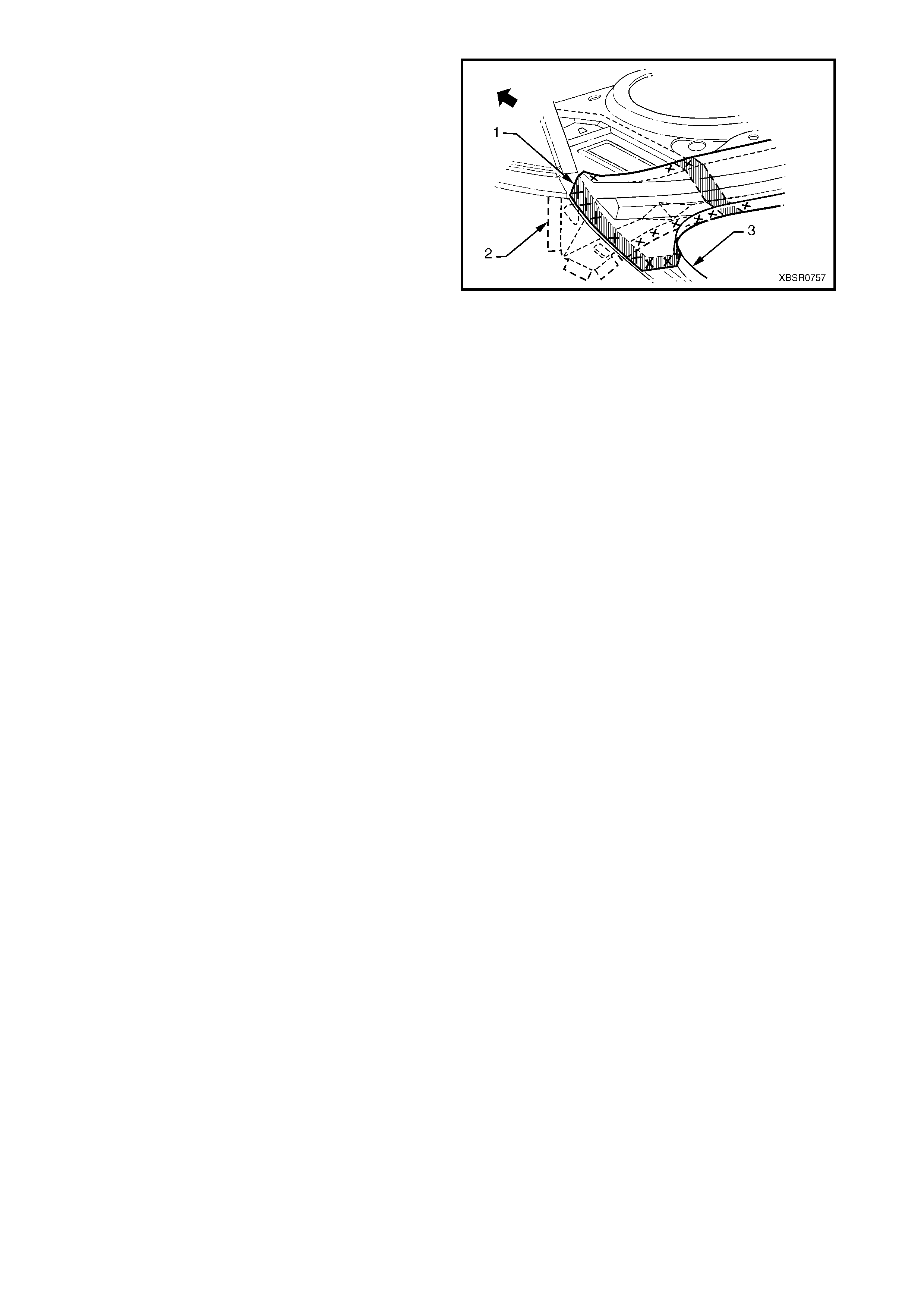
18. Spot or plug weld through the rear window panel
assembly (1), rear seat back extension assembly
(2) and rear quarter panel (3) as shown.
19. Finish installing the rear quarter panel, refer to
2.1 REAR QUARTER PANEL – REPLACE.
20. Refinish and paint panels and other components
as required. Refer to Section 3, 1.3 PAINT
REFINISHING.
21. Apply Joint Sealer (Item 3) as required. Refer to
5. BODY SEALING, ADHESIVES & DEADENERS
in Section 3A.
22. Apply Cavity Wax ( Item 8) as requir ed to the inside
of any box sections or areas inaccessible to paint,
refer to 6. CAVITY WAX in Section 3A.
23. Install the remaining components as described in
the appropriate Section of the MY 2003 VY & V2
Series II Service Information.
Figure 7A-165