
SECTION 7D – BODY SIDE – COUPE
IMPORTANT
Before performing any Service Operation or other procedure described in this Section, refer to
Section 00 CAUTIONS AND NOTES and Section 2 PRECAUTIONS in this Supplement for correct
workshop practices with regard to safety and/or property damage.
CAUTION
The Structure of the M Y 2003 VY & V2 Series II body shell has been developed using complex design
and development techniques. In addition to meeting all required standards, the v ehicle body is also a
critical part of the overall safety systems. It is therefore imperative the repair procedures described
here are adhered to during all vehicle body repairs.
1. GENERAL DESCRIPTION
1.1 BODY SIDE COMPONENTS
2. SERVICE OPERATIONS
2.1 REAR QUARTER PANEL – REPLACE
REMOVE
REPLACE
2.2 TAIL LAMP HOUSING, QUARTER PANEL
UPPER EXTENSION & QUARTER PANEL
LOWER EXTENSION – REPLACE
REMOVE
REPLACE
2.3 DOOR OPENING FRAME ASSEMBLY –
REPLACE
REMOVE
REPLACE
2.4 DOOR OPENING FRAME ASSEMBLY –
PARTIAL REPLACE, HINGE PILLAR
REMOVE
REPLACE
2.5 DOOR OPENING FRAME ASSEMBLY –
PARTIAL REPLACE, CENTRE PILLAR
REMOVE
REPLACE
2.6 DOOR OPENING FRAME ASSEMBLY –
PARTIAL REPLACE, ROCKER PANEL
REMOVE
REPLACE
2.7 FENDER LOWER REAR BRACKET –
REPLACE
2.8 HINGE PILLAR INNER PANEL ASSEMBLY –
REPLACE
REMOVE
REPLACE
2.9 QUARTER PANEL INNER ASSEMBLY –
REPLACE
REMOVE
REPLACE
2.10 QUARTER PANEL INNER ASSEMBLY –
PARTIAL REPLACE
REMOVE
REPLACE
1. GENERAL DESCRI PTI O N
This Section des c ribes the r eplacement proc edur es for the body side components of the MY 2003 V2 Series II body
structure. Removal of bolt-on panels and mechanical components is not covered.
When repairing the body side of the vehicle, care must be taken to ensure the structure is returned to its original
production configuration. This is especially important to maintain side impact standards and for the occupant
protection system to function correctly.
Partial replacement procedures are included for the door opening frame assembly hinge pillar, centre pillar and
rocker panel. These procedures must be followed carefully, as they regularly involve hidden reinforcement panels.
The cutting locations specified are the only places allowable.
A partial replacement procedure is also included for the rear section of the quarter panel inner assembly.
NOTE: It is imperative that the correct body adhesives, sealers, deadeners and cavity waxes are used when
repairing the body structure of MY 2003 V2 Series II vehicles. Refer to 5. BODY SEALING, ADHESIVES &
DEADENERS and 6. CAVITY WAX in Section 3D for details of the correct materials and their commercially
available equivalents.
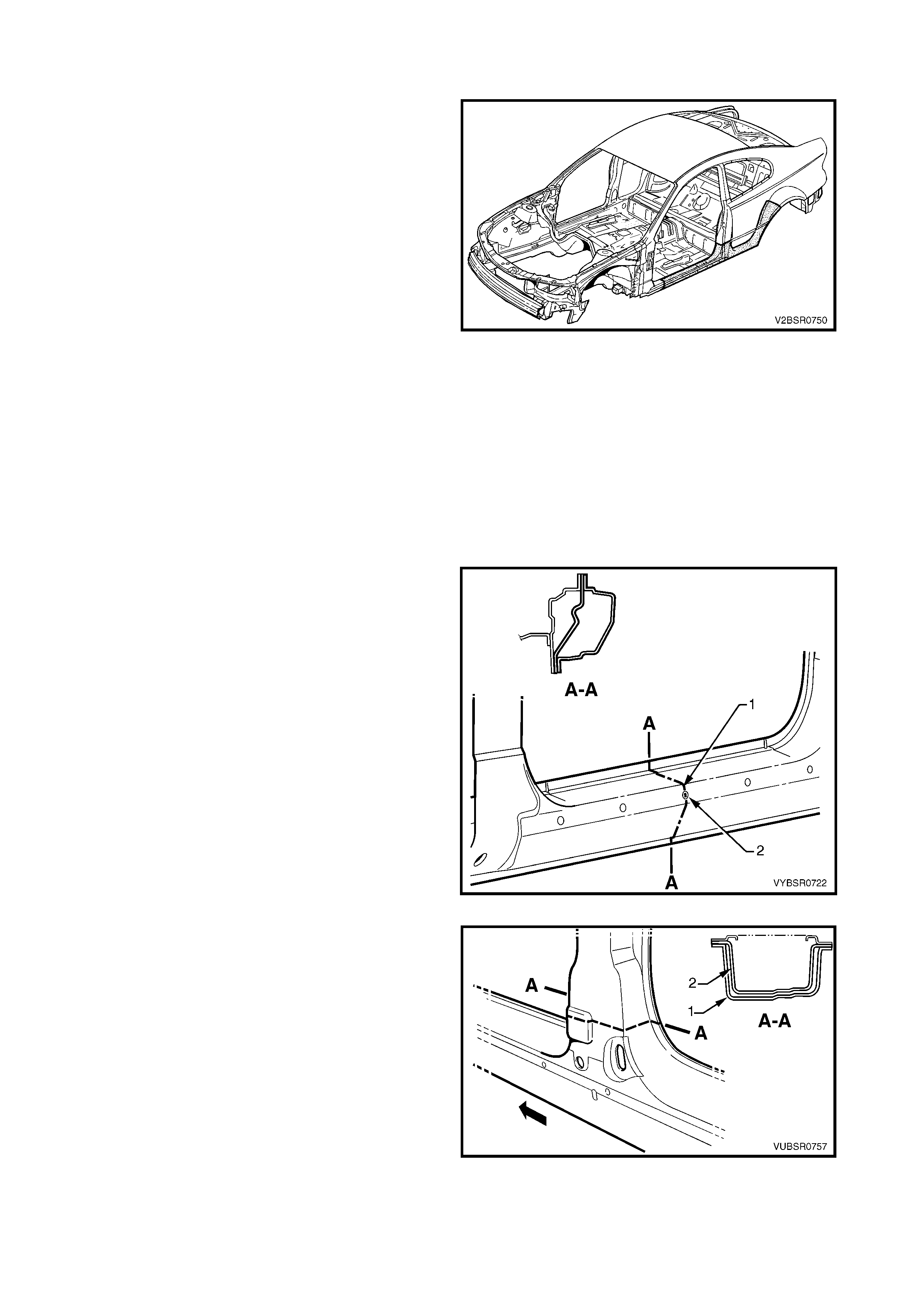
1.1 BODY SIDE COMPONENTS
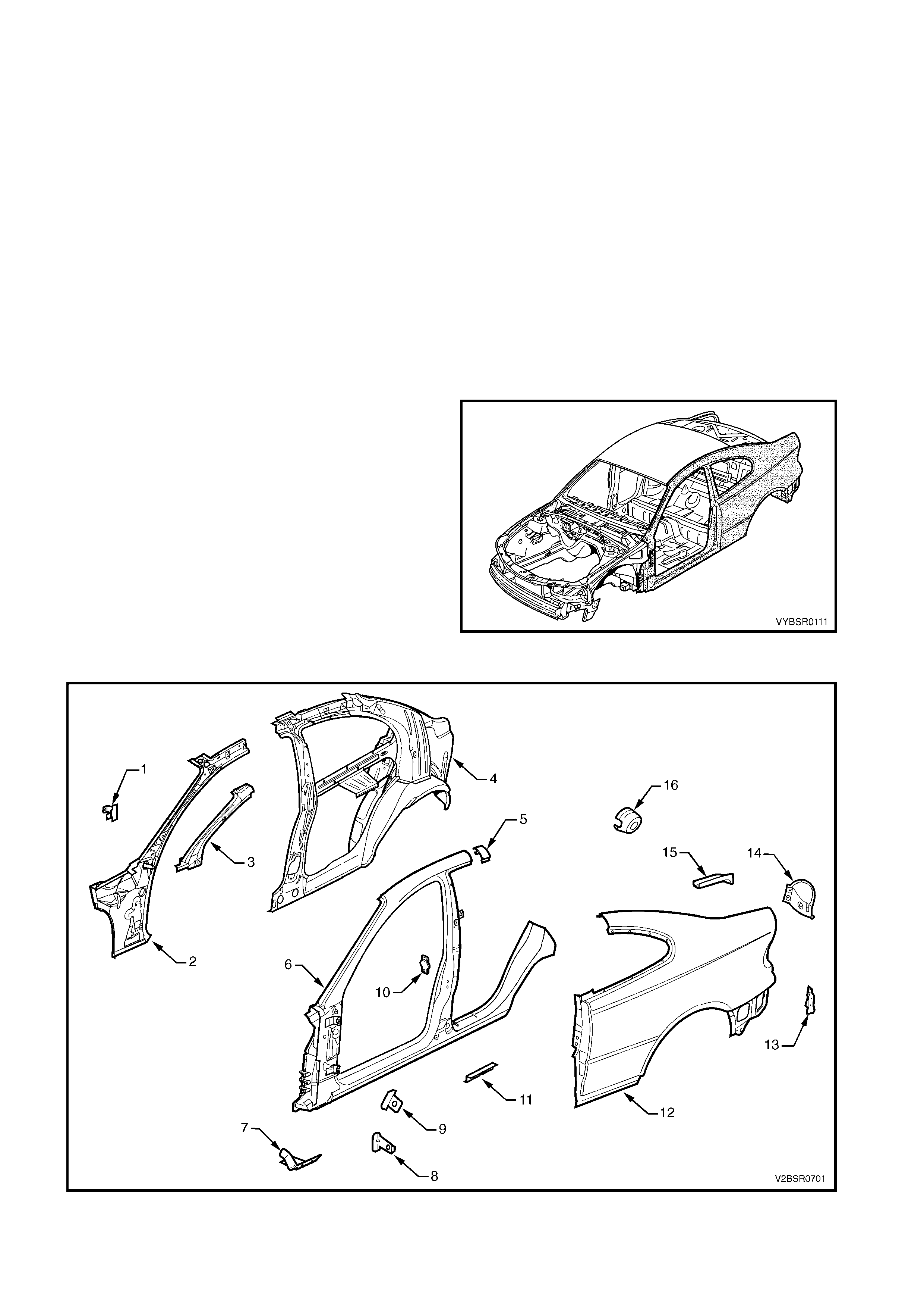
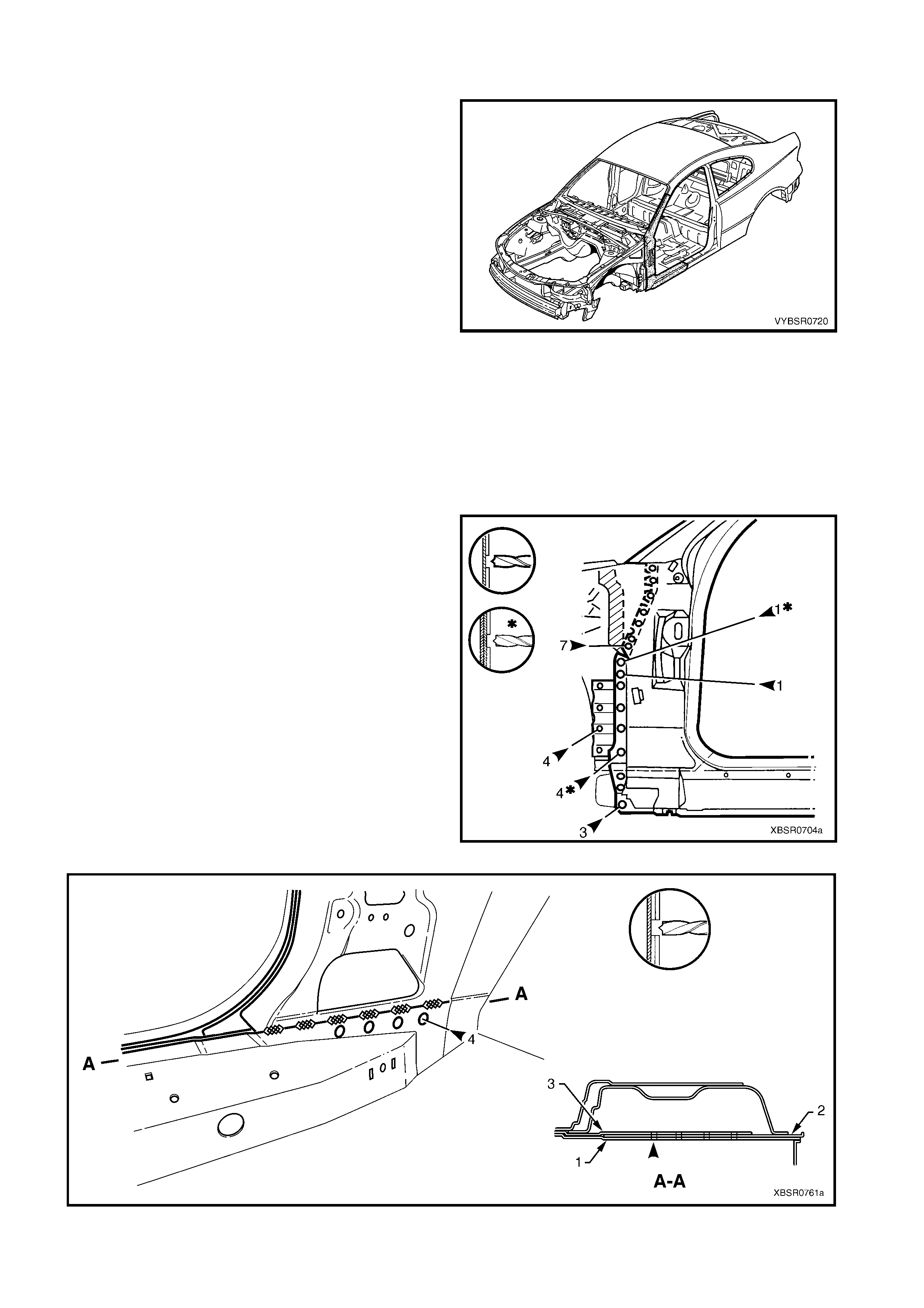
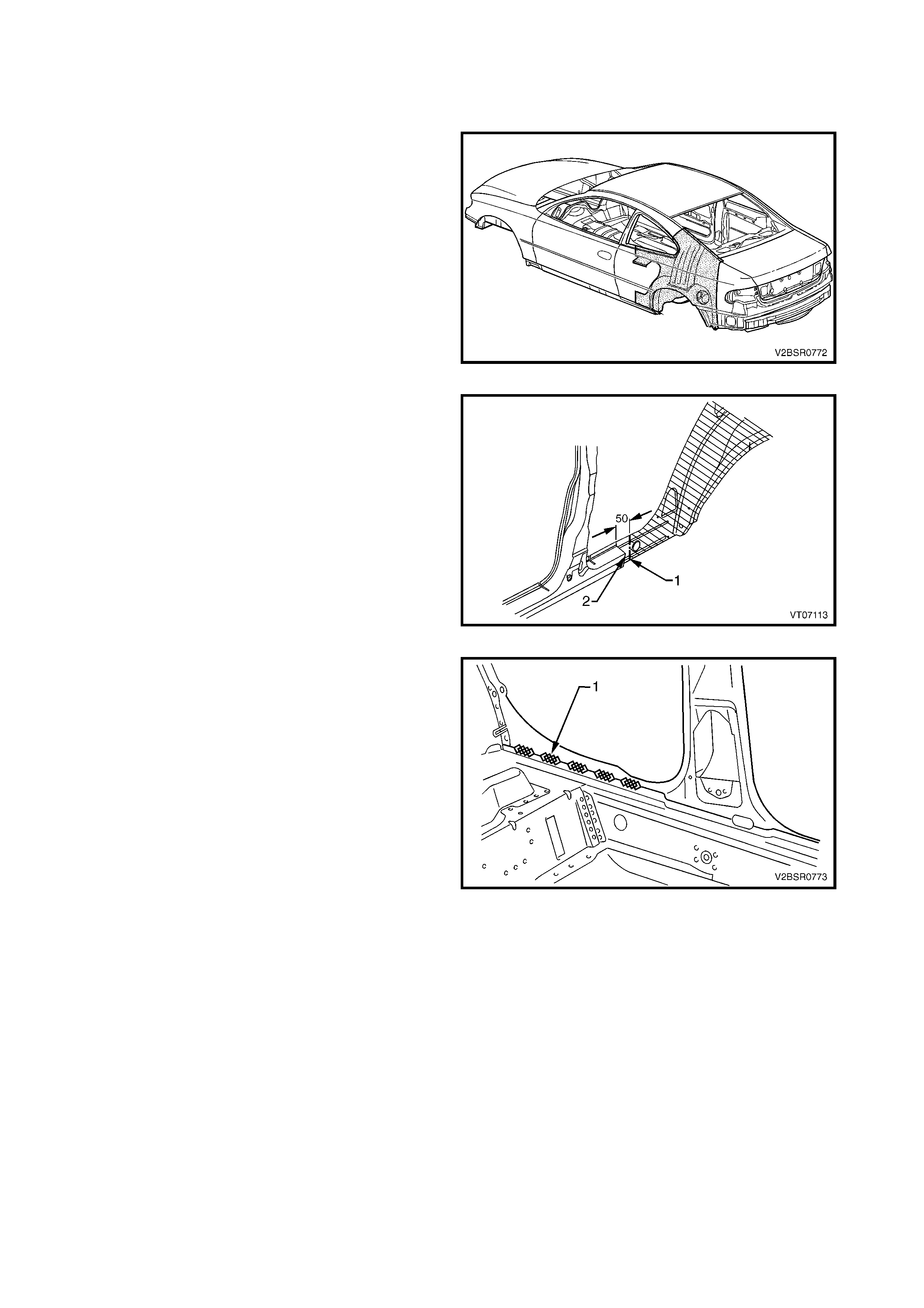
The shaded components in Figure 7D-1 are the body
side component dealt with in this Section.
The components and assemblies shown in Figure 7D-
2 are the parts serviced for MY 2003 V2 Series II
vehicles which form the basis of the repair procedures
in this Section. For a detailed view of the body
components, refer to Section 3D, BODY
CONSTRUCTION – COUPE.
NOTE: Always refer to your Authorised Retailer for
spare parts availability configurations.
IMPORTANT: Cavity foam may be used within the
hinge, centre and lock pillar cavities. Car e needs to be
taken when repairing the vehicle in these areas, refer
to Section 2, 10. CAVITY FOAM, prior to beginning
any work, for further information. Figure 7D-1
Figure 7D-2

Legend
1. Hinge Pillar Trim Panel Bracket
2. Hinge Pillar Inner Panel Assembly
3. Hinge Pillar Upper Reinforcement
4. Quarter Panel Inner Assembly
5. Body Pillar Inner Panel Reinforcement
6. Door Opening Frame Assembly
7. Fender Lower Rear Bracket
8. Fender Rear Bracket
9. Fender Upper Rear Bracket
10. Front Door Striker Anchor Plate
11. Underbody Jacking Locator
12. Rear Quarter Panel
13. Quarter Panel Lower Extension
14. Tail Lamp Housing
15. Quarter Panel Upper Extension
16. Fuel Filler Pipe Housing
NOTE 1: The door opening frame assembly includes parts 7, 8, 9, 10 and 11.
NOTE 2: The quarter panel inner assembly includes the rear wheelhouse inner panel assembly which is also
available separately, refer Section 10D BODY REAR – COUPE.
2. SERVICE OPERATIONS
2.1 REAR QUARTER P ANEL – REPLACE
NOTE 1: The rear quarter panel is not available as an
assembly with the tail lamp housing, quarter panel
upper extension, quarter panel lower extension or fuel
filler pipe housing (for right-hand side).
This procedure details the removal of the rear quarter
panel as an assembly with the above parts.
Replacement of the smaller panels is described in this
and the subsequent procedure.
NOTE 2: Full replacement of the rear quarter panel
requires removal of the roof panel. An alternative is
also provided in this procedure where the panel is
joined through the lock-pillar, approximately 100 mm
below the top of the rear window.
NOTE 3: Cavity Foam is used within the hinge,
centre and lock pillar cavities. Care is required
when repairing the vehicle in these areas, refer to
Section 2, 10. CAVITY FOAM prior to beginning
work for further information.
REMOVE
CAUTION: To avoid the possibility of fire, take
particular care when cutting or welding at the rear
of the vehicle. Remove the fuel tank and plug all
fuel lines.
1. Remove the adjacent bolt-on panels and
components as described in the appropriate
Section of the MY 2003 VY & V2 Series II Service
Information.
2. Remove the rear window and quarter window
assembly, refer to Section 1A6 STATIONARY
WINDOWS in the MY 2003 VY & V2 Series II
Service Information.
3. Remove the rear bumper impact bar, refer to
Section 3, 2. BUMPER IMPACT BAR
ASSEMBLIES.
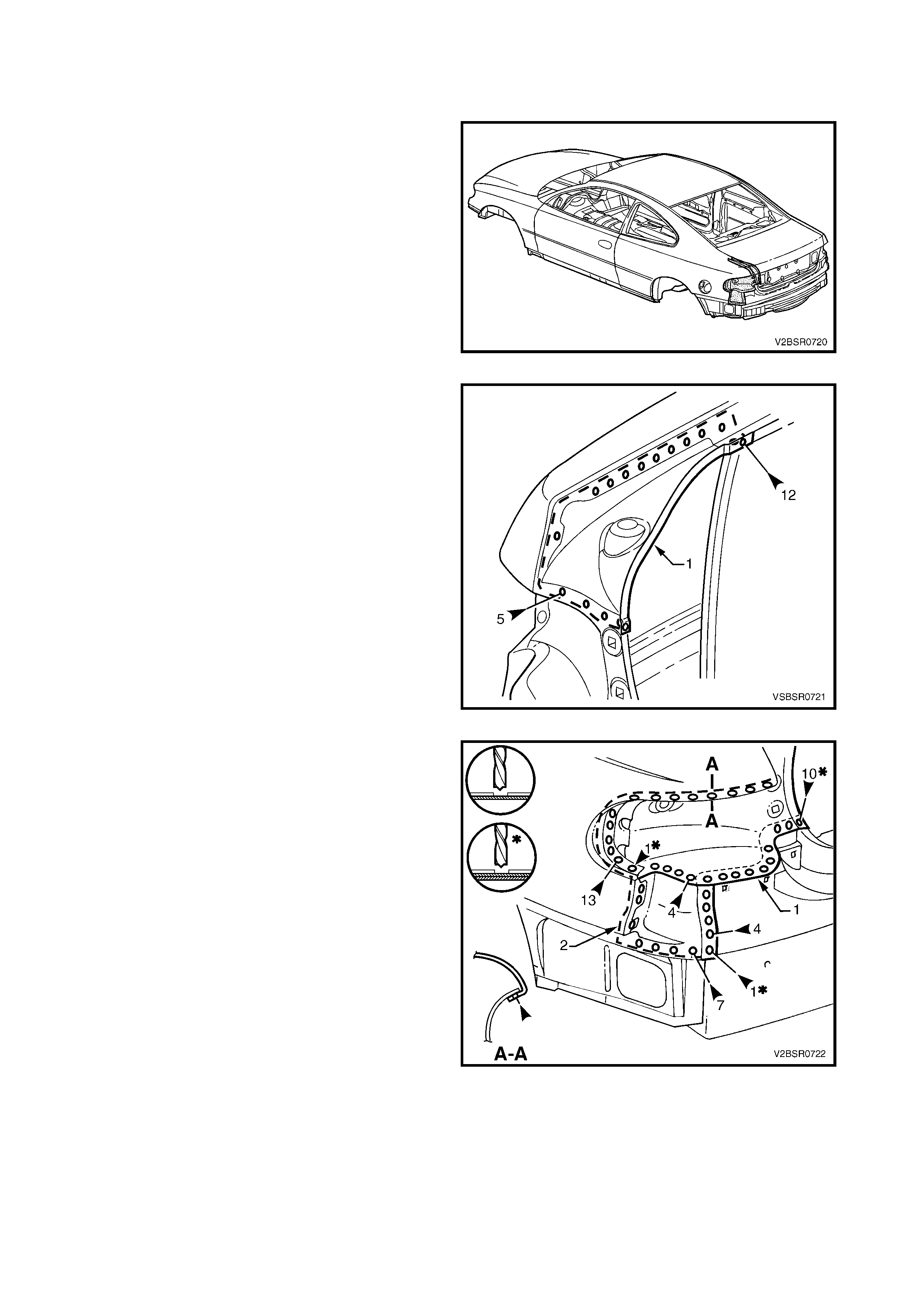
Figure 7D-3
4. Spot cut the tail lamp housing and quarter panel
lower extension from the rear end lower panel.
NOTE: If the tail lam p hous ing and quarter panel lower
extension are to remain, modify this procedure
accordingly .
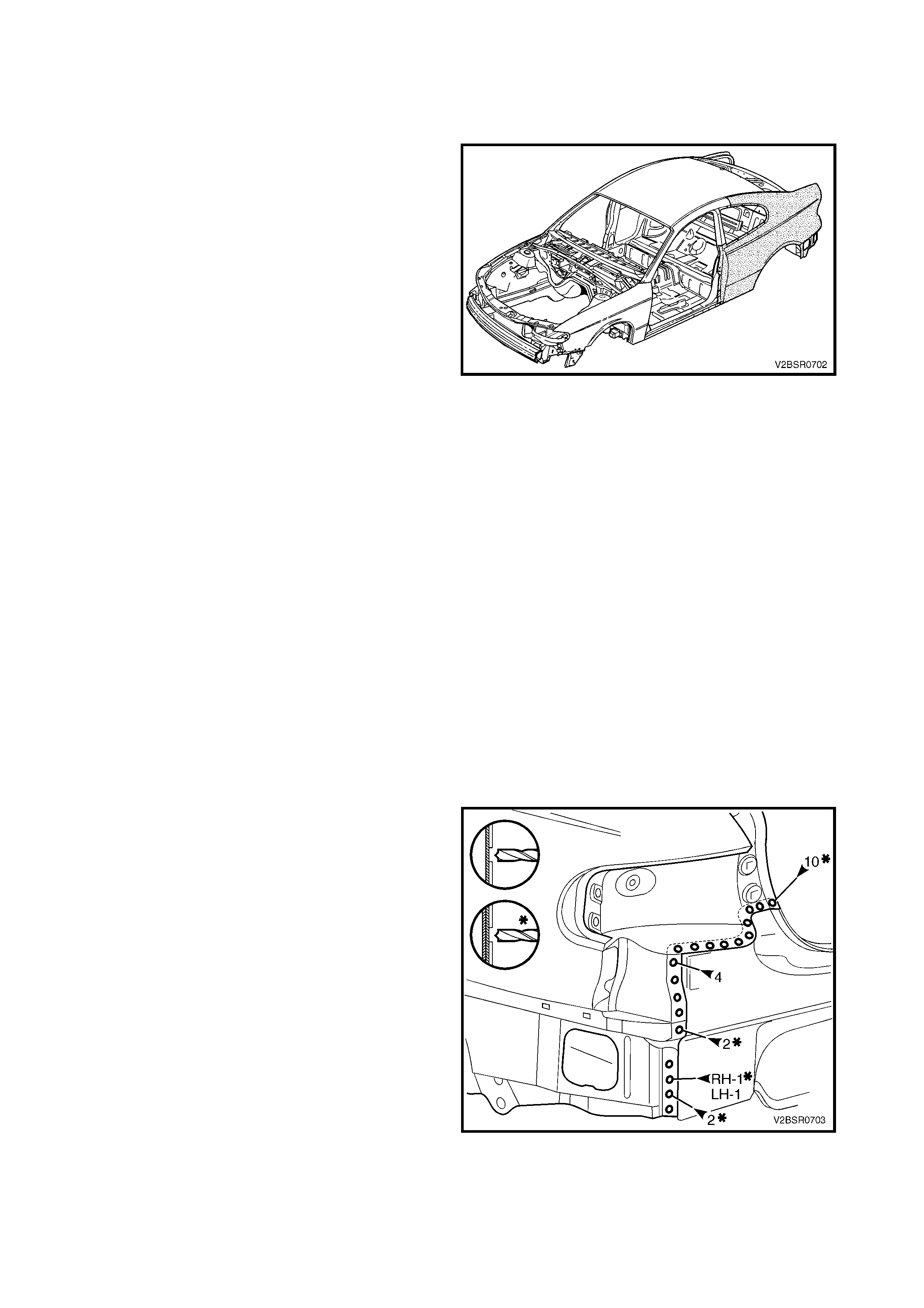
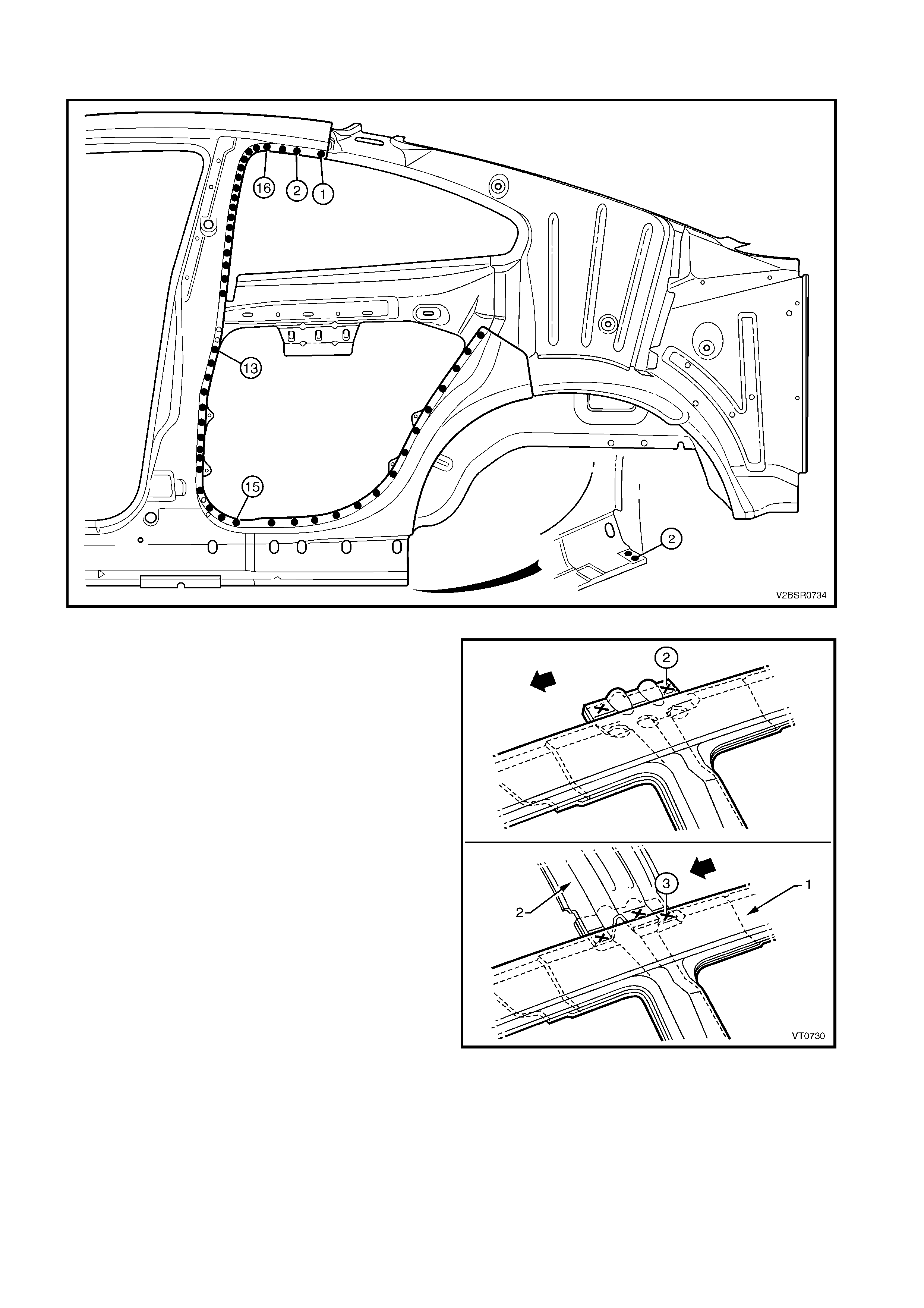
5. Spot cut the rear quarter panel from the rear end
lower panel and rear compartment floor panel
outer extension.
6. Spot cut the welds attaching the rear quarter panel
to the quarter panel inner assembly and rear
compartment floor panel outer extension. There
are a different number of welds on the left-hand
panel to the right-hand panel. Refer to Figure
7D-5.
Figure 7D-4
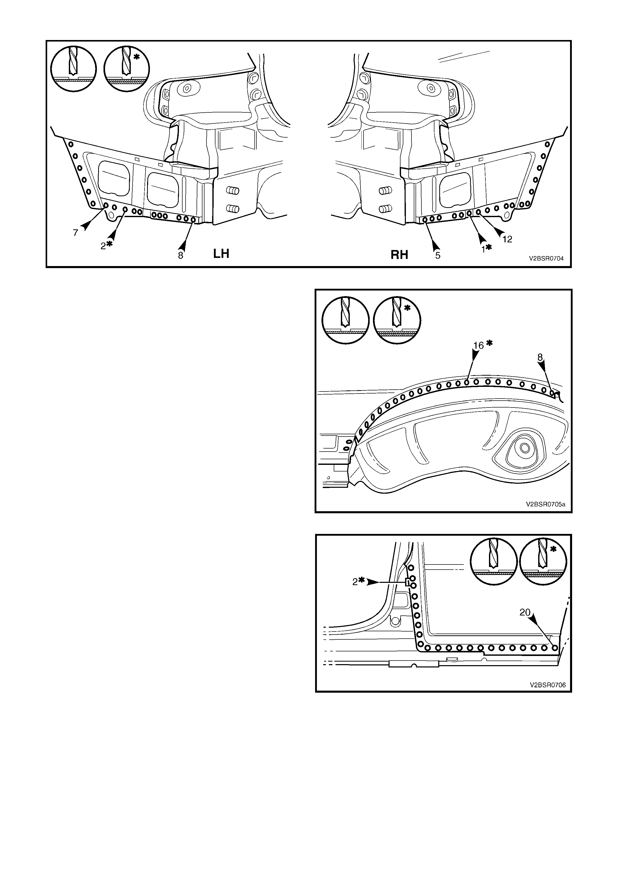
Figure 7D-5
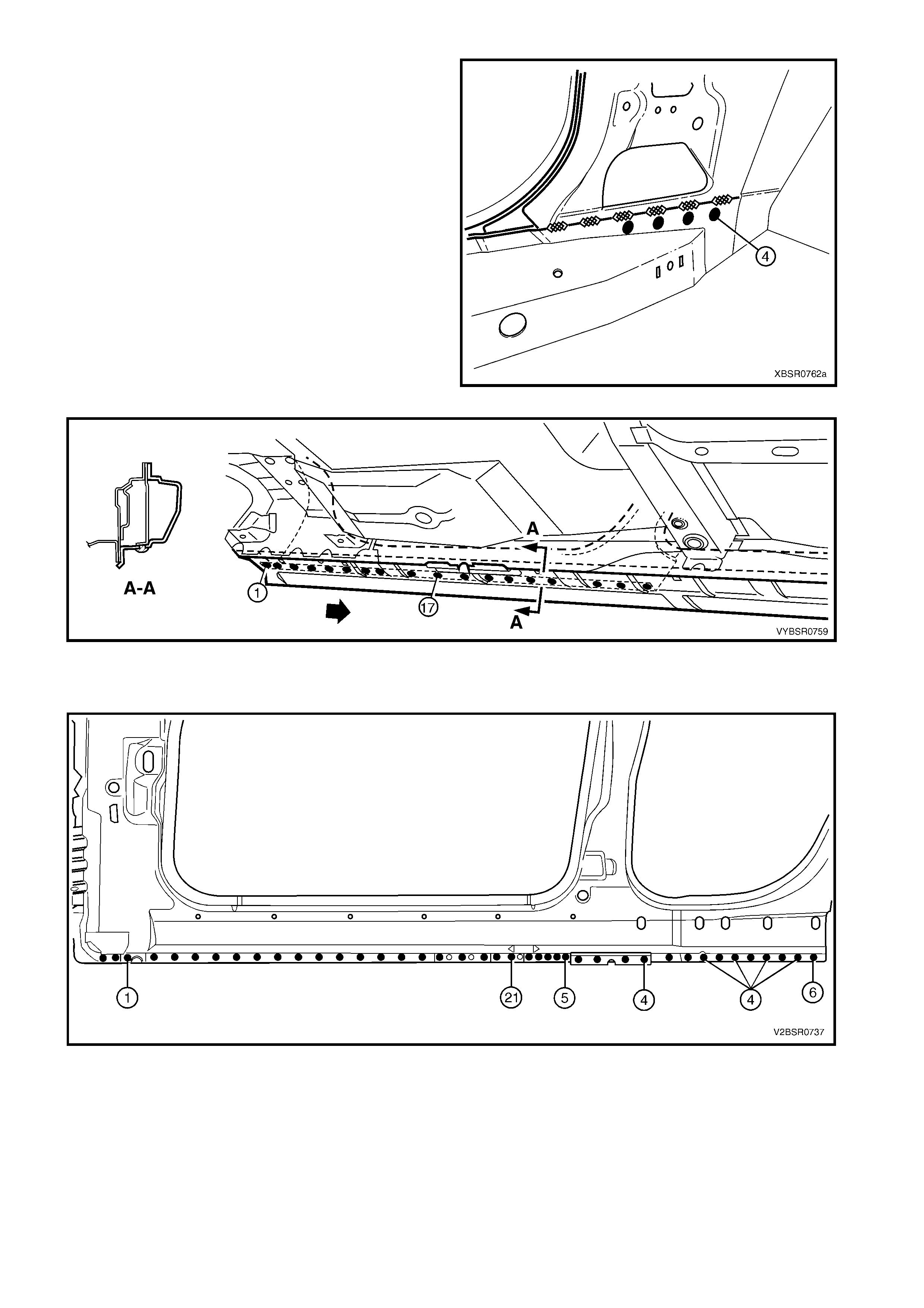
7. Spot cut the welds attaching the rear quarter panel
to the door opening frame assembly and quarter
panel inner assembly.
Figure 7D-6
8. Spot cut the welds attaching the rear quarter panel
to the door opening frame assembly.
Figure 7D-7
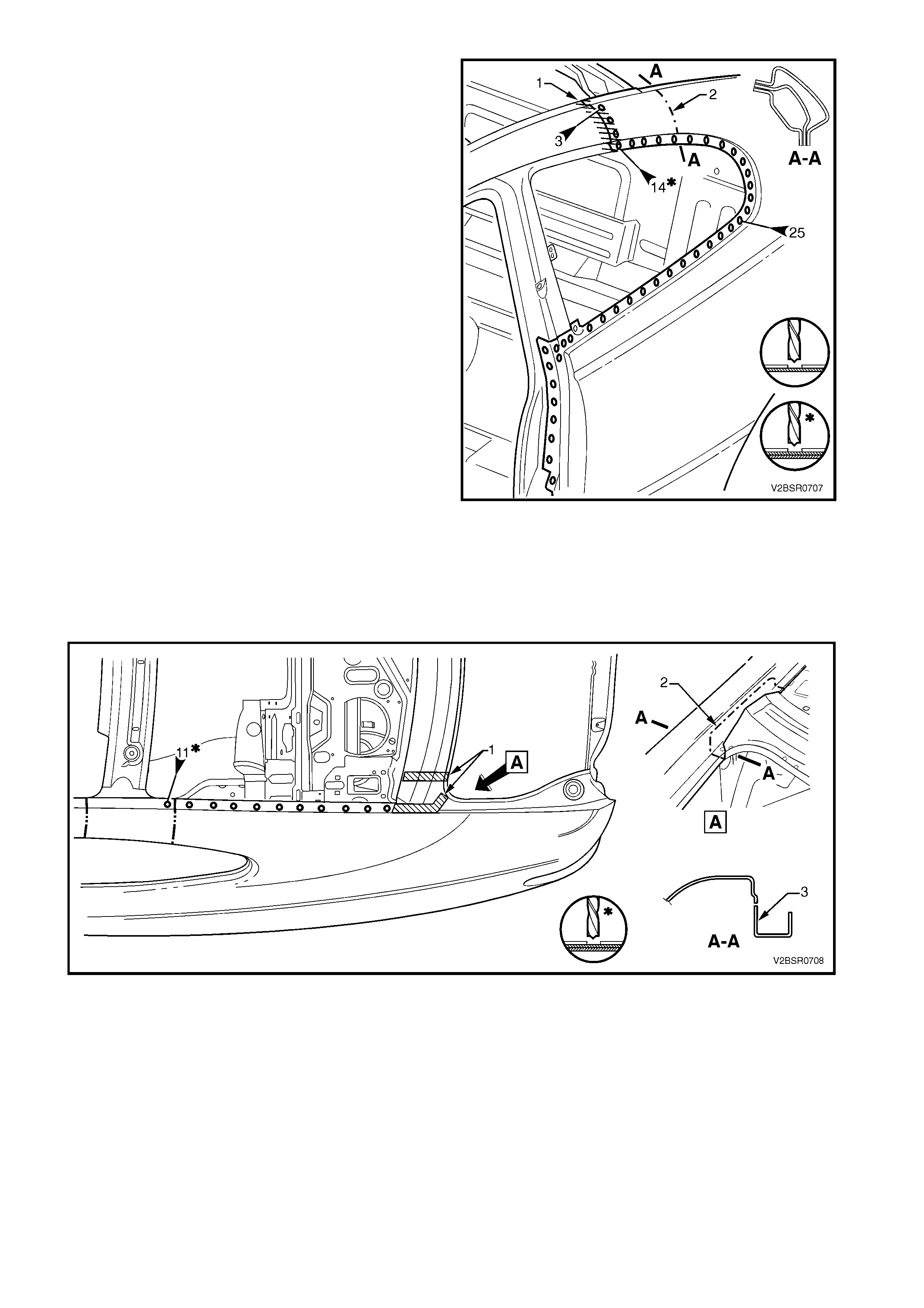
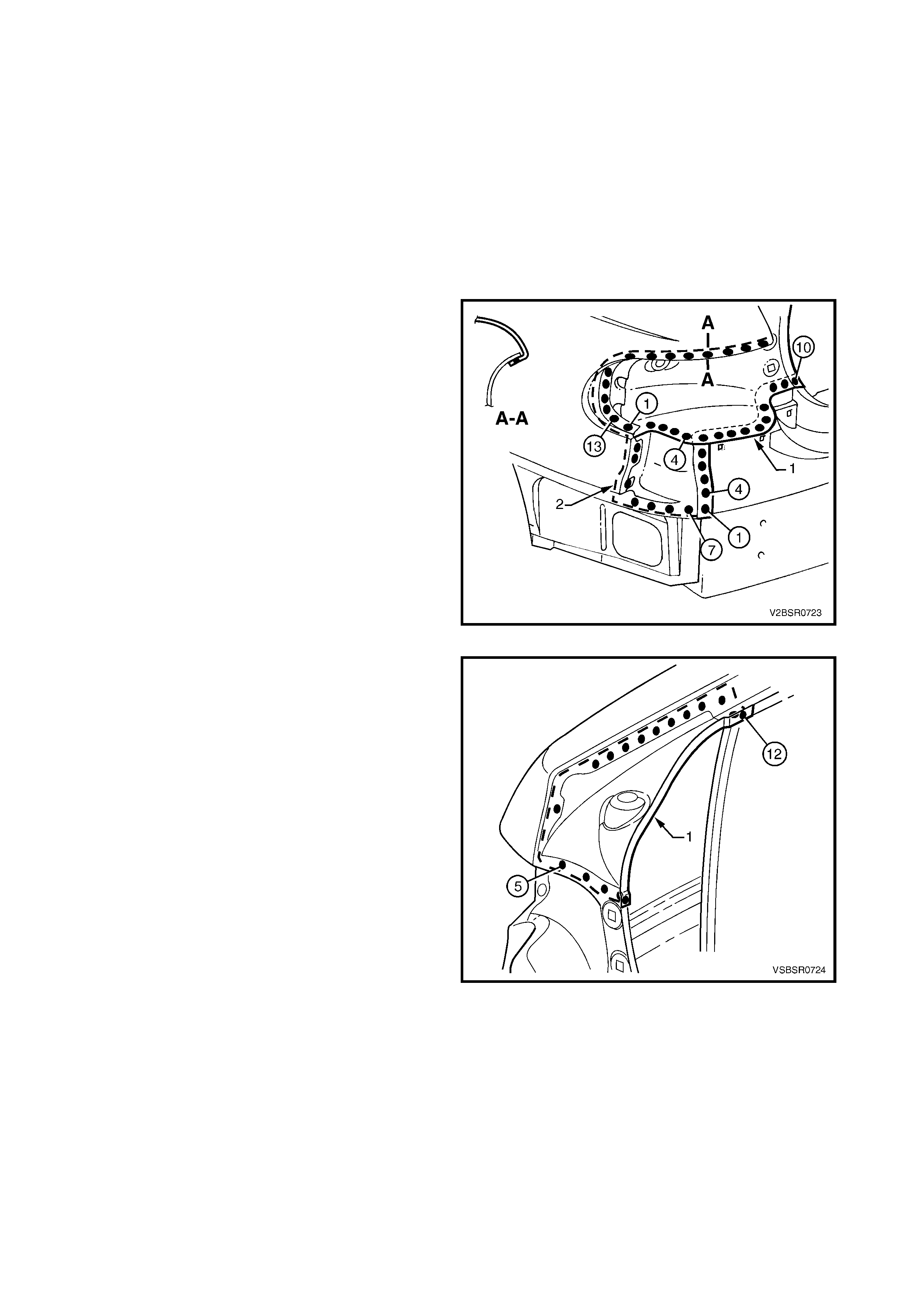
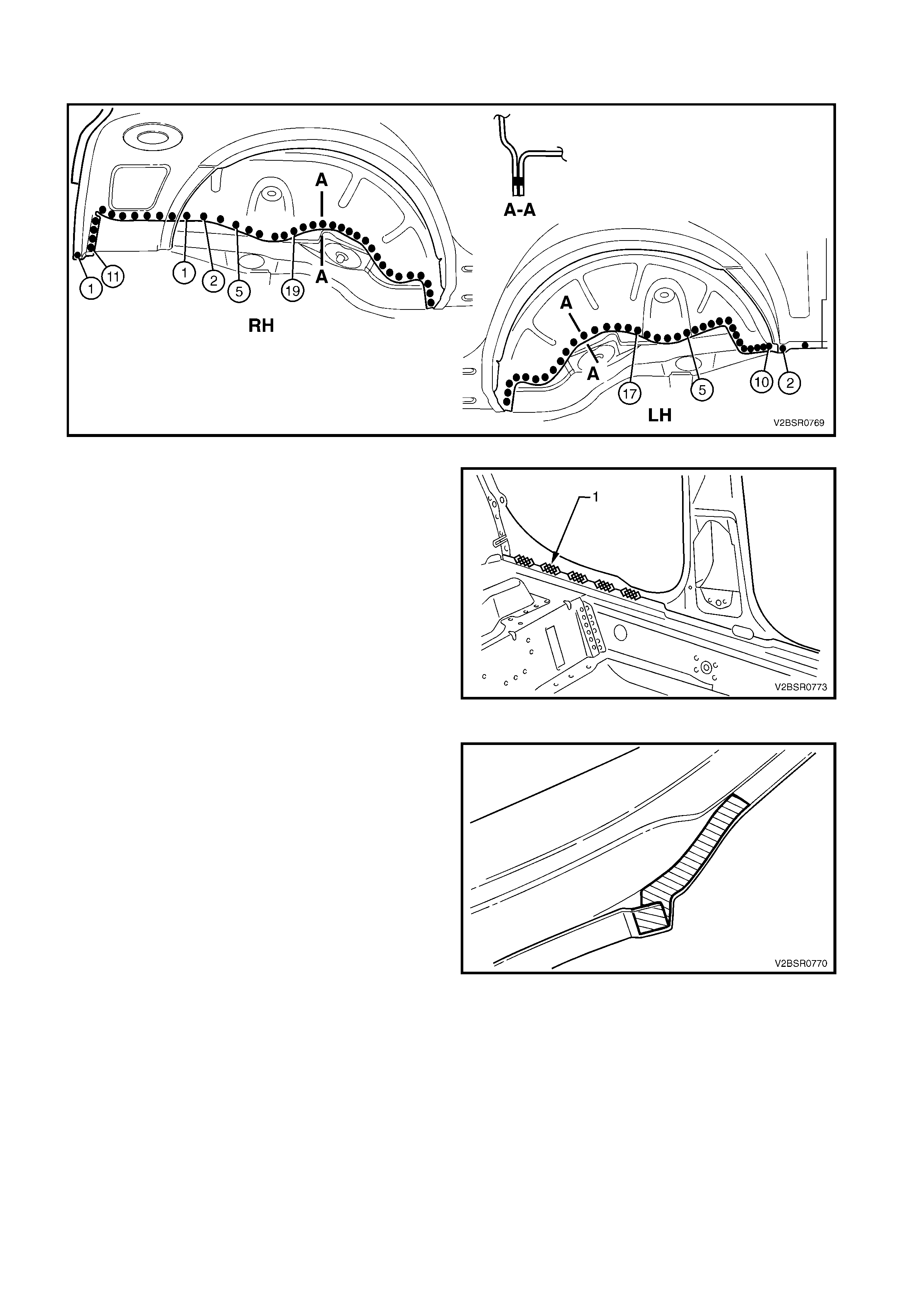
9. Spot cut the welds attaching the rear quarter panel
to the door opening frame assembly and quarter
panel inner assembly.
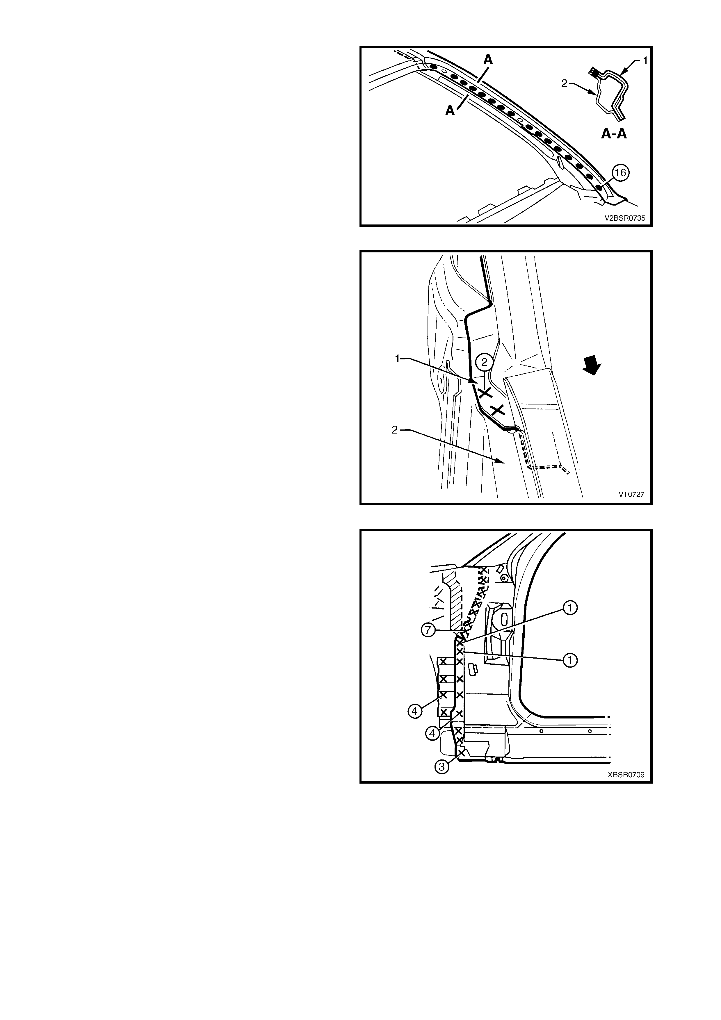
NOTE: If the roof panel has been removed, cut the
welds all the way along the quarter window opening to
the braze joint (1). Remove the three welds attaching
the rear quarter panel to the body pillar inner panel
reinforcement and using an oxy / acetylene torch and
wire brush, carefully remove the brazing from the joint.
If the roof panel has not been removed, only remove
the spot welds as far as point (2). Mark a line and cut
the rear quarter panel at this area, ensuring not to cut
into the quarter panel inner assembly.
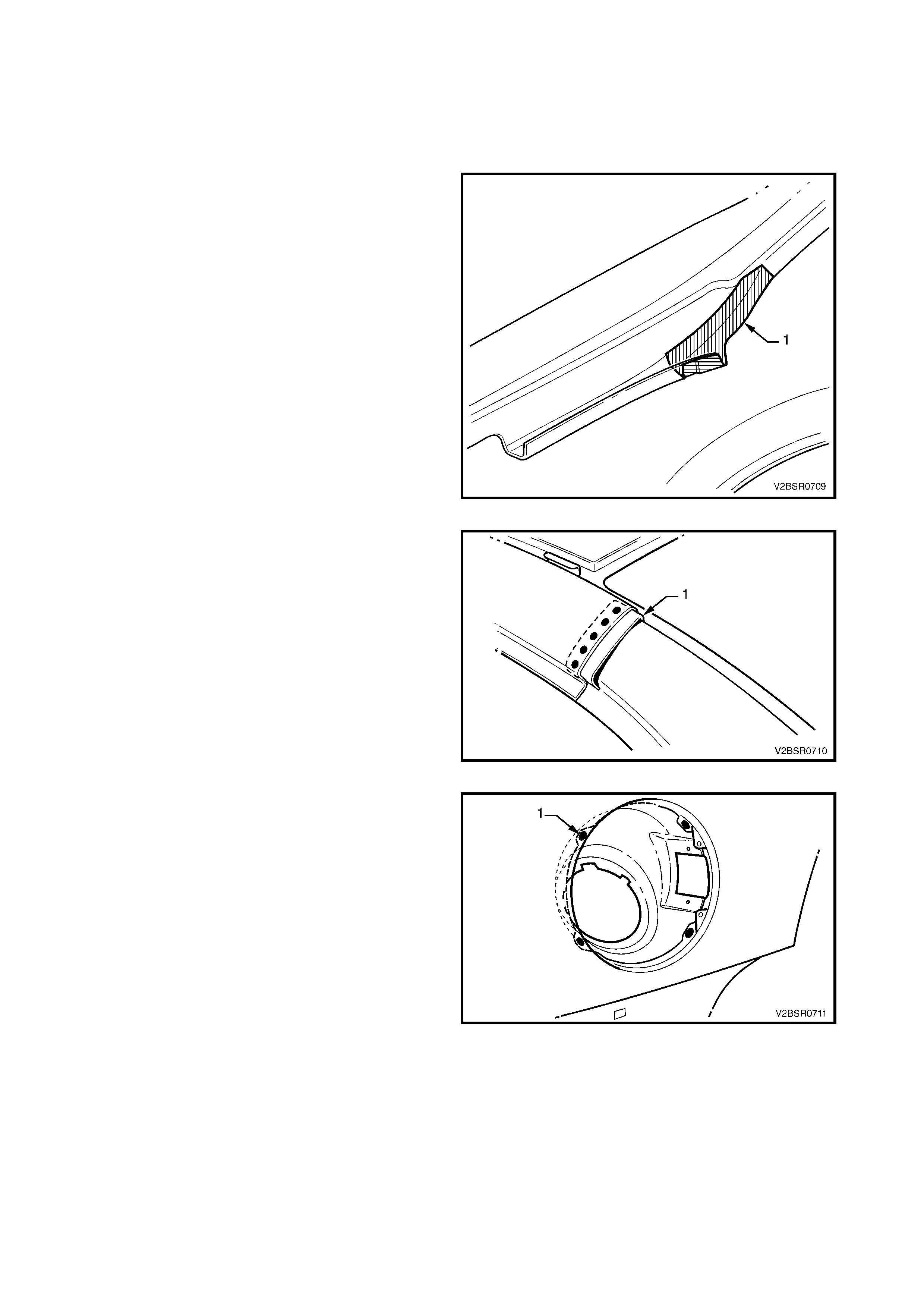
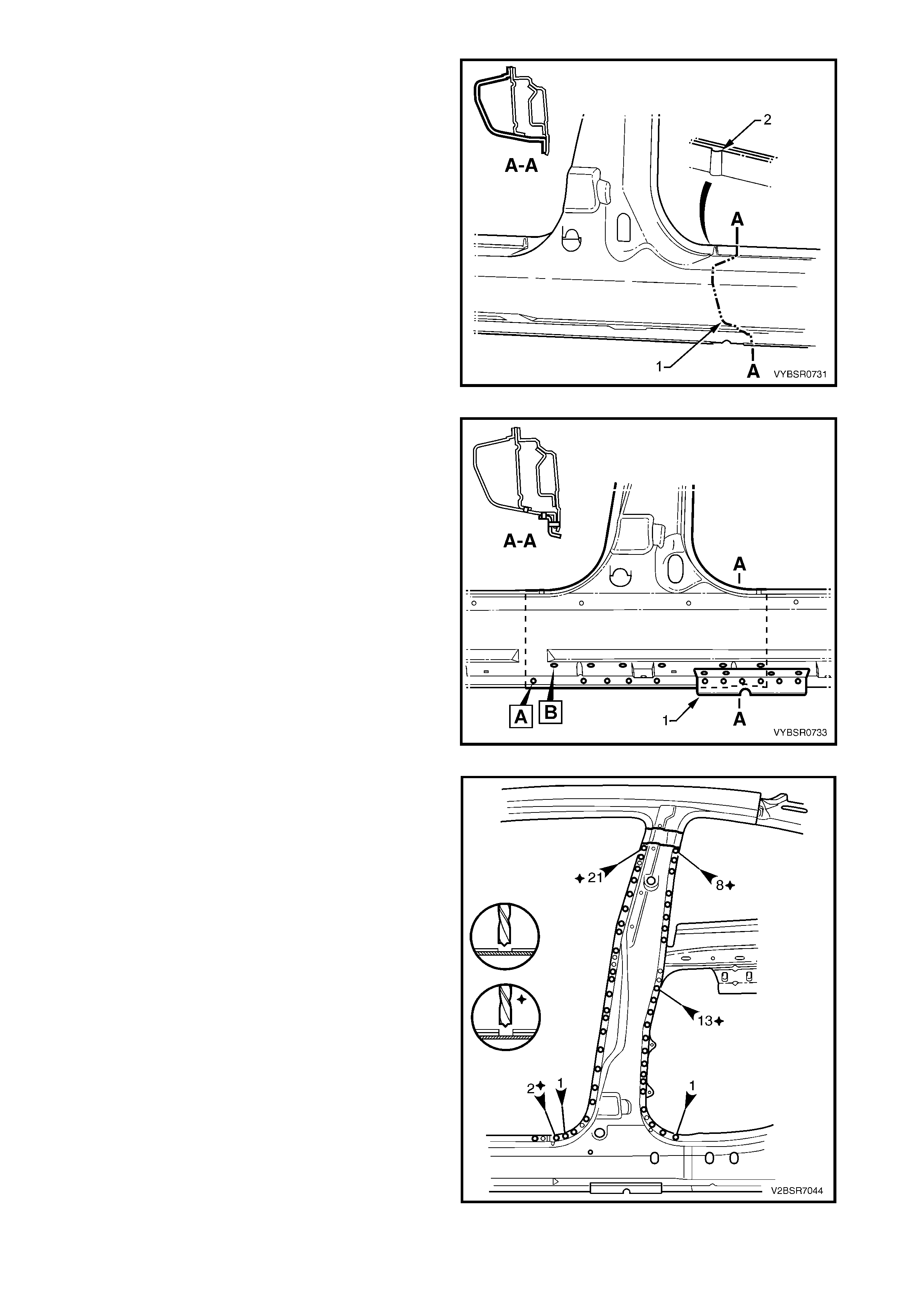
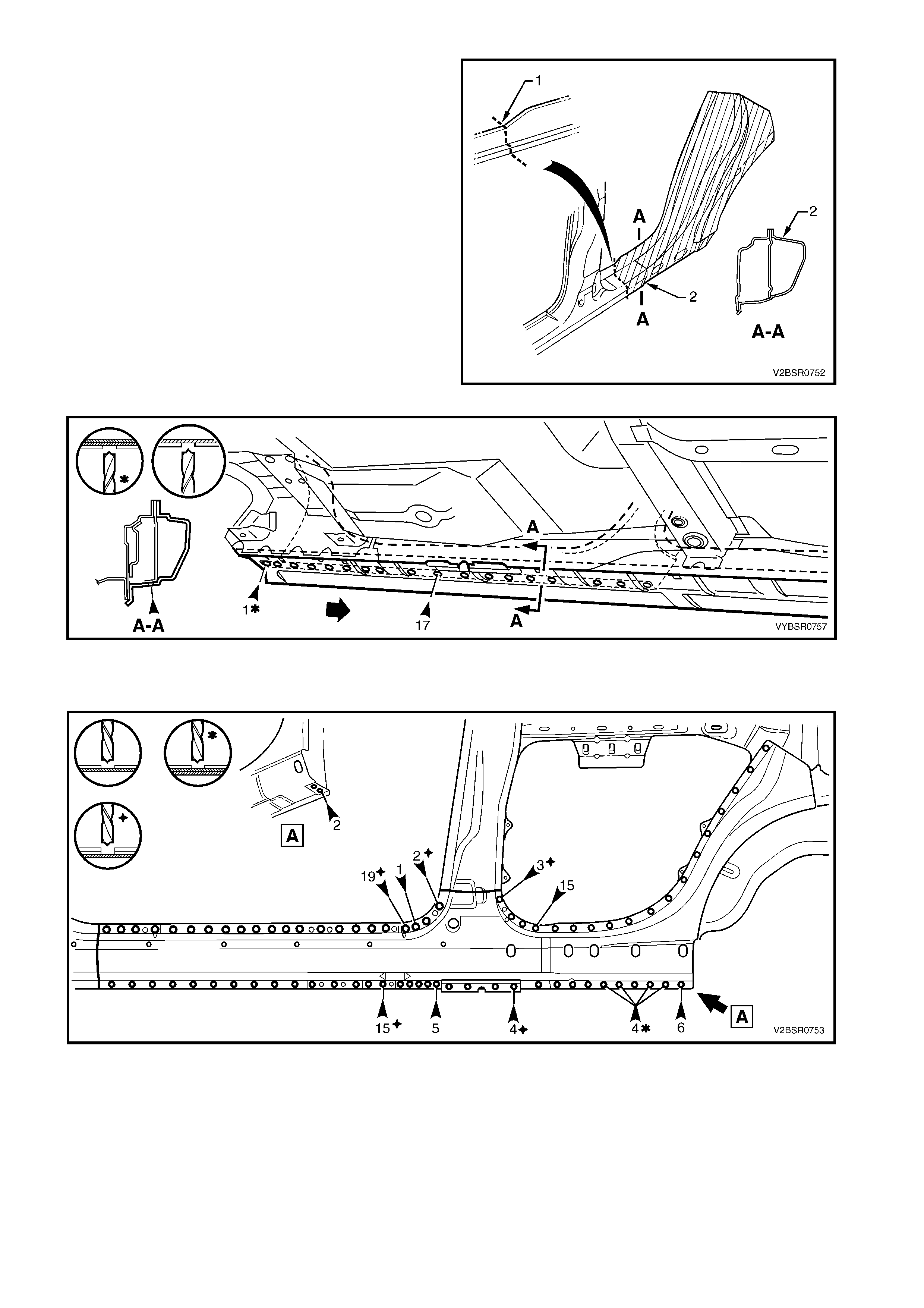
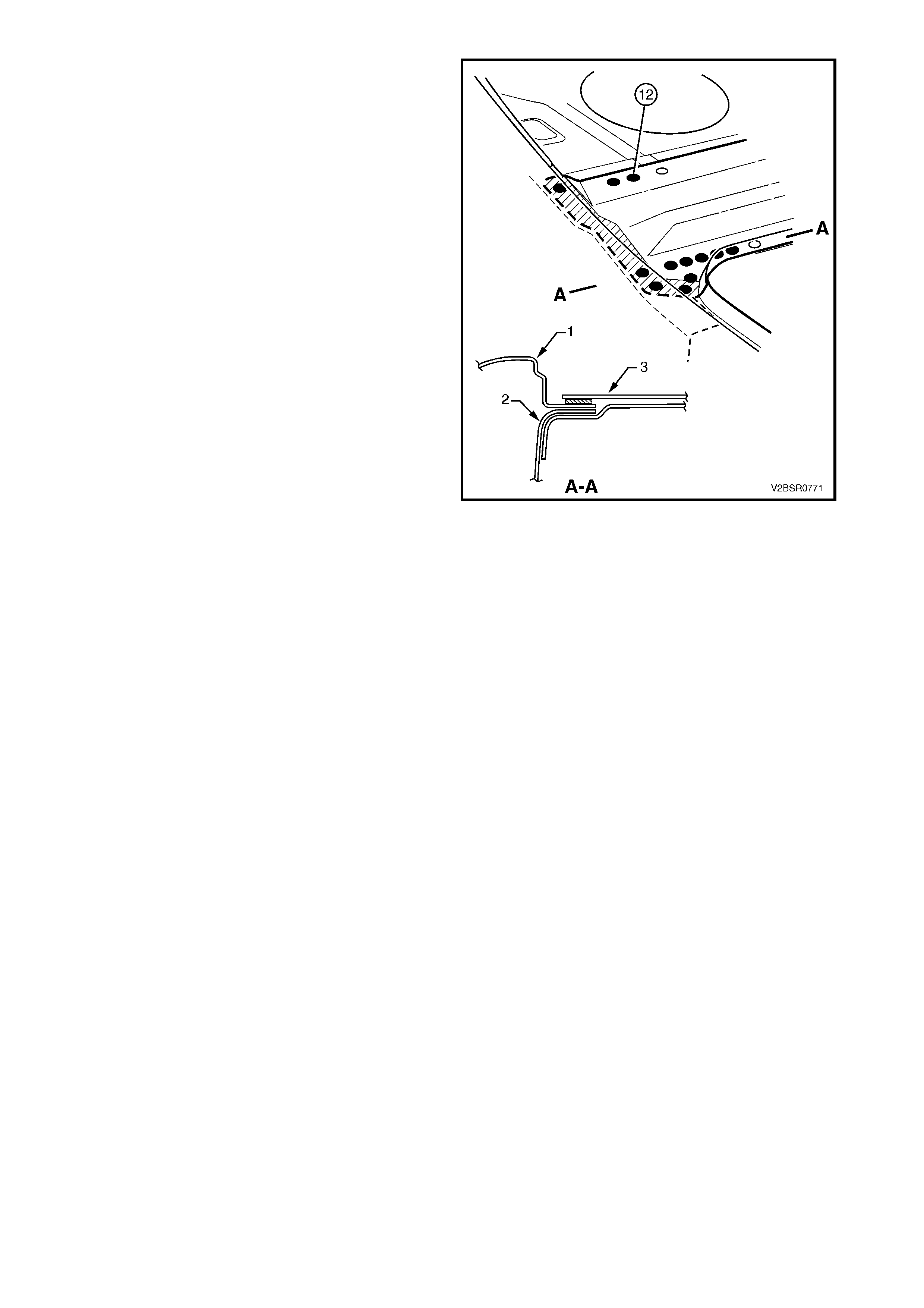
10. At the base of the loc k pillar, the rear quar ter panel
is sandwiched between the quarter inner panel
assembly and rear window panel assembly.
Cutting the panel at this point, as desc ribed below,
rather than removing extra panels, will save
considerable tim e and ef fort as s tructural adhesive
(1) is used in this area, refer to Figure 7D-9.
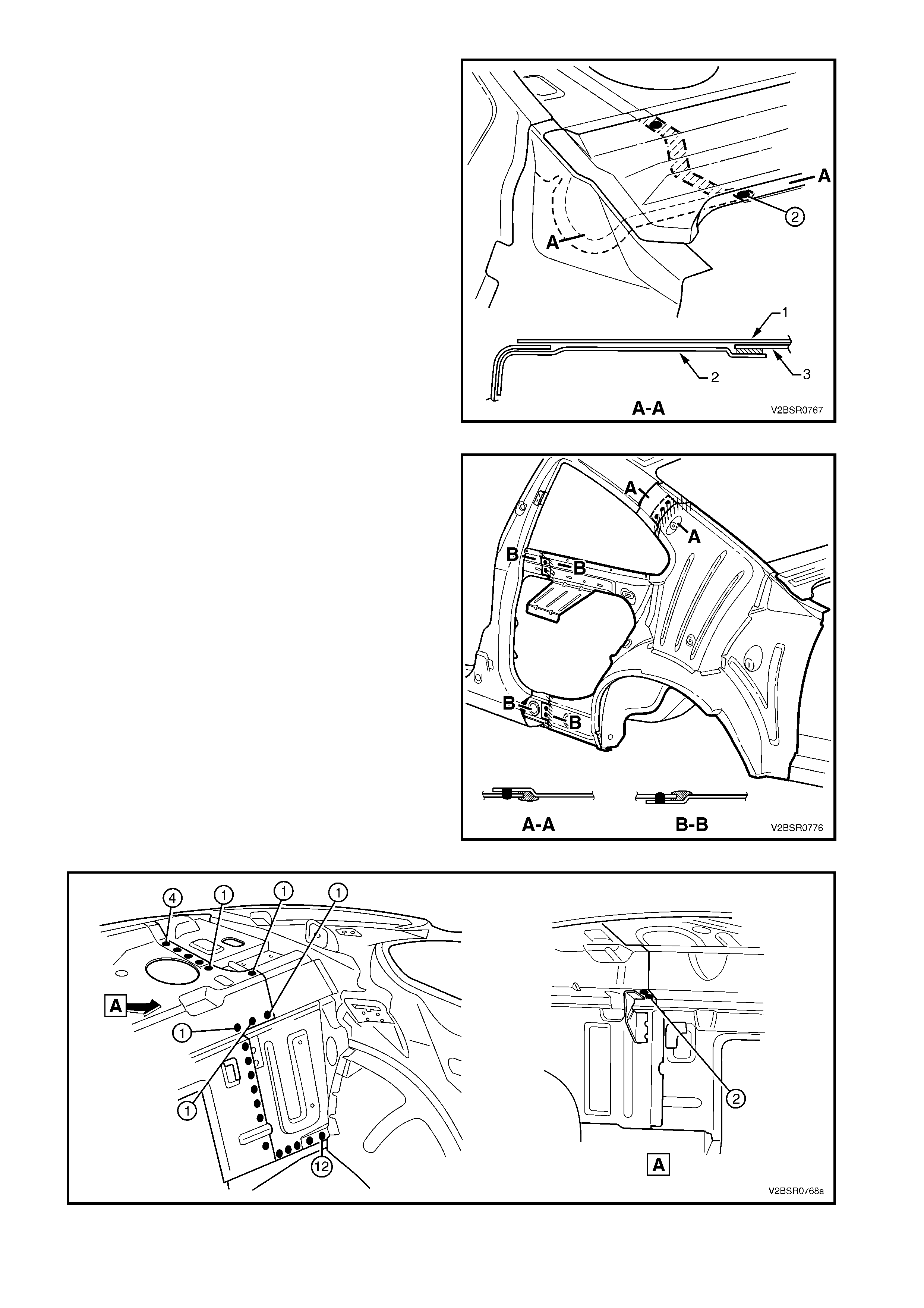
11. Using a saw or other appropriate equipment, cut
through the rear quarter panel as shown (2) at
View A. The cut should pass across the drain
channel, then along the inner face of the rear
quarter panel.
NOTE: It is important to leave enough material (3) to
facilitate a lap joint of the old and new panels. The
drain channel and rear window opening flange will be
butt joined.
12. As required spot cut the welds attaching the rear
quarter panel to the quarter panel inner assembly.
Figure 7D-8
Figure 7D-9
13. Remove the panel from the vehicle and then repair any damage to adjacent parts.
NOTE: For the right-hand side, the fuel filler pipe housing is attached to the quarter inner panel assembly with
acrylic spot weld sealer, which will require separating while the panel is being removed.
14. Check and rectify the alignment of the body as required, refer to 3. BODY DIMENSIONS in Section 3D.
REPLACE
NOTE 1: Spot welding is the preferred method for attaching of panels and should be used whenever possible.
Where the spot welding equipment will not access the required weld position, a plug weld should be performed.
NOTE 2: The s ame number and pos ition of spot welds ( or plug welds) s hould be used when replac ing the panel,
as was used during manufacture, in order to maintain the original structural strength of the vehicle.
1. On the replacement panel, remove the section (1)
to facilitate the join at the base of the lock pillar.
IMPORTANT: If surrounding panels have been
replaced, this section may be required to remain intact.
2. If the roof panel has not been removed, remove
the upper section of the lock pillar on the new
panel to match the removed panel.
Figure 7D-10
3. From the scrap piece, manufacture a
reinforcement (1) to fit inside the remaining rear
quarter panel on the vehicle as shown.
NOTE: The reinforcement must not extend to the
flanges.
4. Mark the panel with drilling locations in preparation
for plug welding. Drill holes as required.
5. Prepare all mating surfaces and treat with Weld
Through Primer (Item 1) as required, refer to
5. BODY SEALING, ADHESIVES & DEADENERS
in Section 3D.
6. Clam p the reinforcem ent in position and plug weld
it to the vehicle.
Figure 7D-11
7. For the right-hand side, if required spot or plug
weld (1) the fuel filler pipe housing to the rear
quarter panel in four places.
Figure 7D-12
8. Open the flange (1) at the base of the lock pillar
outwards slightly to allow the new panel to seat
correctly.
9. As required, mark the new panel with drilling
locations in prepar ation f or plug welding. Drill holes
as required.
10. Prepare all mating surfaces and treat with Weld
Through Primer (Item 1) as required, refer to
5. BODY SEALING, ADHESIVES & DEADENERS
in Section 3D.
11. Apply Acrylic Spot Weld Sealer (Item 2), refer to
5. BODY SEALING, ADHESIVES & DEADENERS
in Section 3D.
12. Clamp the rear quarter panel in position ensuring it
is seated correctly at the base of the lock pillar (2).
13. Test fit the alignm ent of the rear quarter panel with
the front door and rear compartment lid.
Figure 7D-13
14. Spot or plug weld the rear quarter panel to the
quarter panel inner assembly.
Figure 7D-14
15. Spot or plug weld the rear quarter panel to the
door opening frame assembly and quarter panel
inner assembly.
NOTE: If the roof panel was rem oved, weld all the way
along the quarter window opening to the braze joint (1).
Plug weld the rear quarter panel to the body pillar inner
panel reinforcement and using an oxy / acetylene
torch, carefully braze weld the joint.
If the roof panel was not removed, weld only as far as
point (2). Plug weld the rear quarter panel to the
manufactured reinforcement and using an oxy /
acetylene torch, carefully braze weld the joint.
IMPORTANT: To reduce the risk of panel distortion,
place wet rags adjacent to the braze joints.
Figure 7D-15
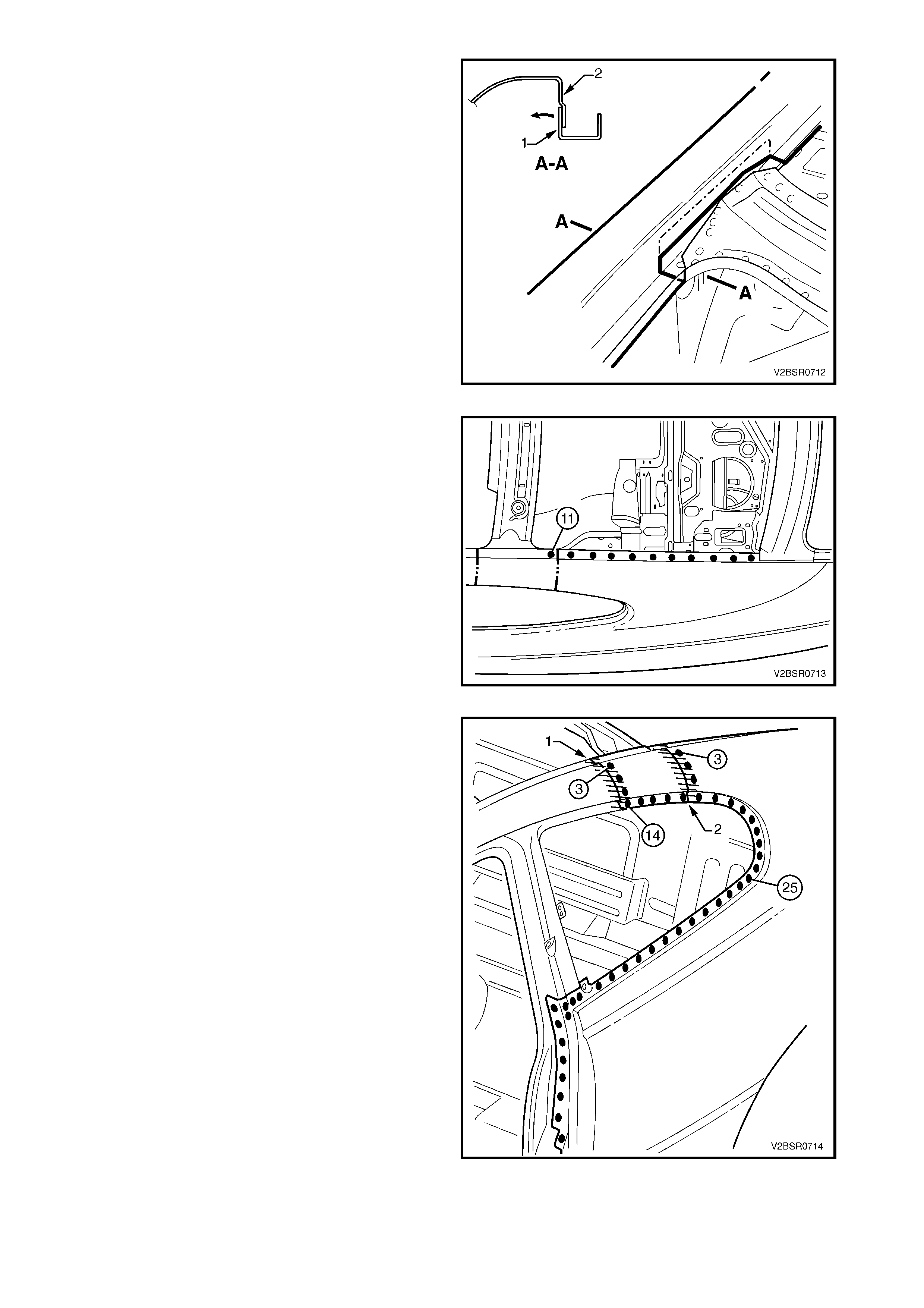
16. Spot or plug weld the rear quarter panel to the
door opening frame assembly .
Figure 7D-16
17. Spot or plug weld the rear quarter panel to the
door opening frame assembly and rear quarter
panel inner assembly.
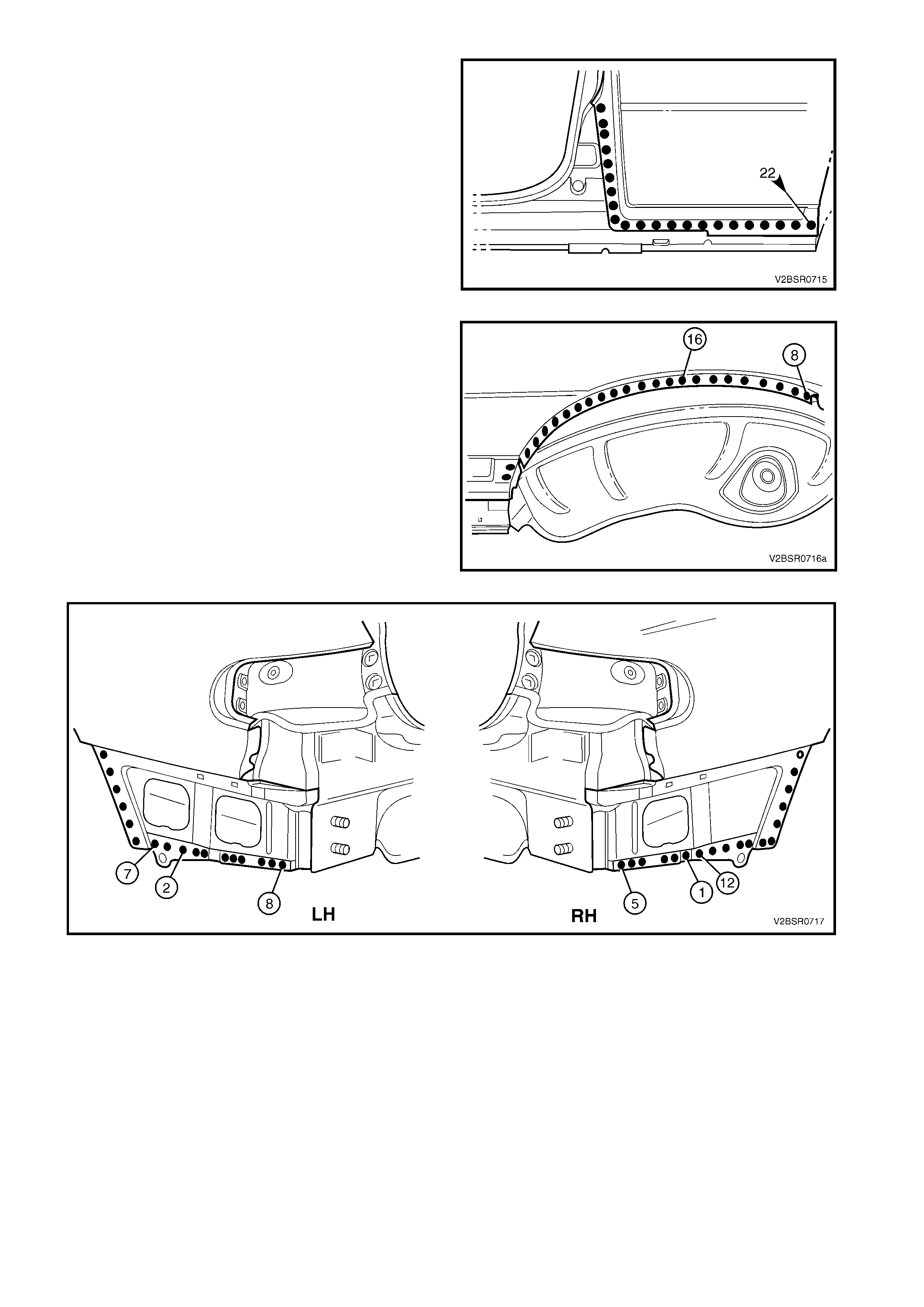
18. Spot or plug weld the r ear quar ter panel to the rear
quarter panel inner assembly and rear
compartment floor panel outer extension. There
are a different number of welds on the left-hand
side to the right-hand side, refer to Figure 7D-18.
Figure 7D-17
Figure 7D-18
19. Spot or plug weld the rear quarter panel to the
flange at the base of the lock pillar and MIG butt
weld across the water channel and rear window
flange.
20. Either:
a. Install the tail lamp housing, quarter panel
lower extension and quarter panel upper
extension, or
b. Weld the rear quarter panel to these panels.
Refer to the following procedure in this Section
21. Refinish and paint panels and other components
as required. Refer to Section 3, 1.3 PAINT
REFINISHING.
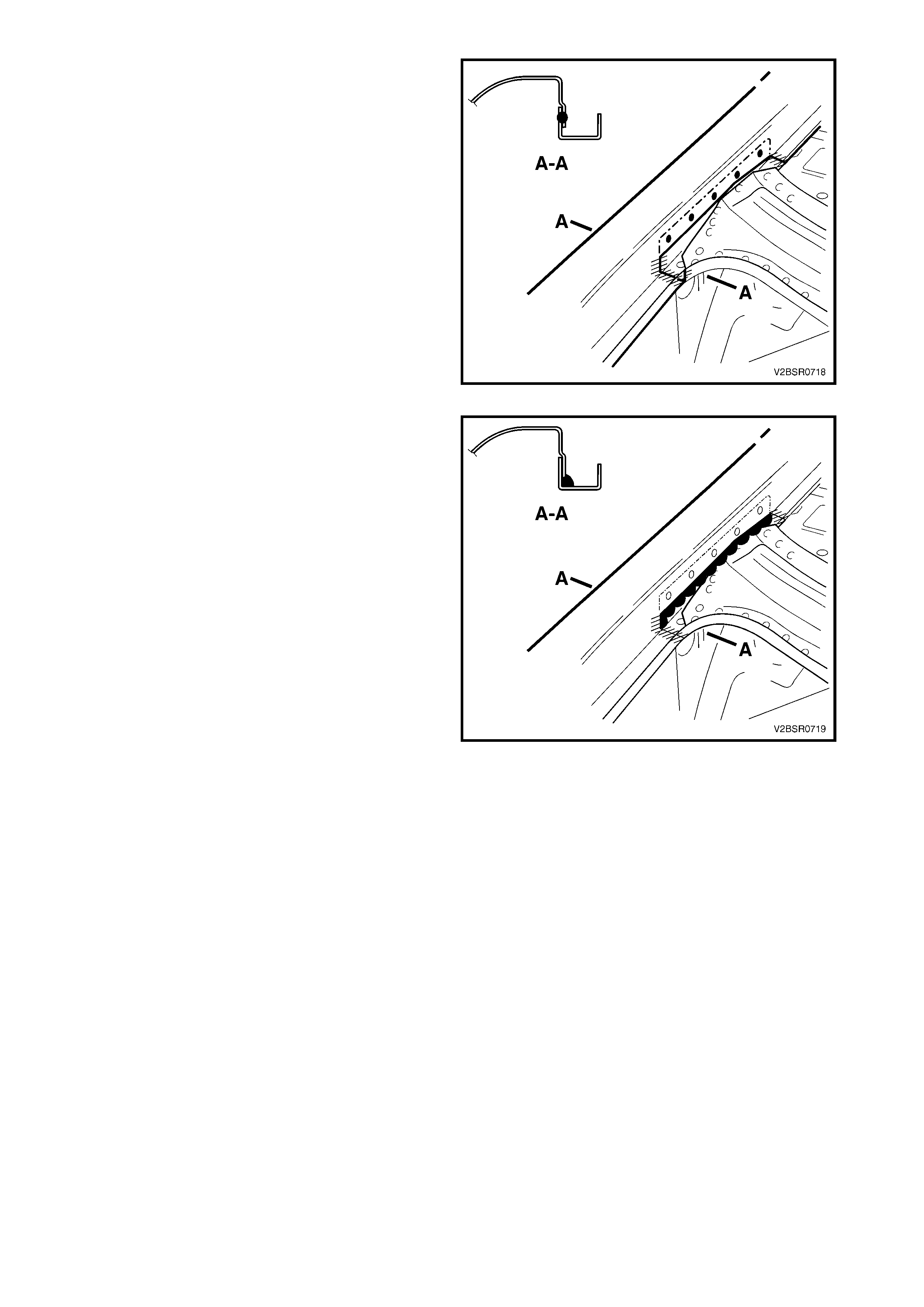
22. Apply Joint Sealer (Item 3) as required. Refer to
5. BODY SEALING, ADHESIVES & DEADENERS
in Section 3D.
Figure 7D-19
23. Add an additional bead of Joint Sealer to the lap
joint at the base of the lock pillar.
24. Apply Cavity Wax (Item 8) as r equired to the inside
of any box sections or areas inaccessible to paint,
refer 6. CAVITY WAX in Section 3D.
25. Install rear bum per impact bar, refer to Section 3,
2. BUMPER IMPACT BAR ASSEMBLIES.
26. Insert Cavity Foam into the lock pillar as required,
refer to Section 2, 10. CAVITY FOAM.
27. Install the remaining components as described in
the MY 2003 VY & V2 Series II Service
Information.
Figure 7D-20
2.2 TAIL LAMP HOUSING, QUARTER PANEL UPPER EXTENSION &
QUARTER PANEL LOWER EXTENSION – REPLACE
NOTE: The components described in this procedure
may be replaced as an assembly or individually as
required.
CAUTION: To avoid the possibility of fire, take
particular care when cutting or welding at the rear
of the vehicle. Remove the fuel tank and plug all
fuel lines.
REMOVE
1. Remove the adjacent bolt-on panels and
components as described in the appropriate
Section of the MY 2003 VY & V2 Series II Service
Information.
Figure 7D-21
2. Spot cut the welds attaching the quarter panel
upper extension (1) to the rear quarter panel and
to the tail lamp housing as required.
Figure 7D-22
3. Spot cut the welds attaching the tail lamp housing
(1) to the rear quarter panel, quarter panel lower
extension (2) and rear end lower panel.
4. The quarter panel lower extens ion (2) m ay then be
rem oved fr om the vehicle by s pot cutting the welds
attaching it to the rear quarter panel and rear end
lower panel.
5. Repair any damage to adjacent parts as required.
Figure 7D-23
REPLACE
NOTE 1: Spot welding is the preferred method for attaching of panels and should be used whenever possible.
Where the spot welding equipment will not access the required weld position, a plug weld should be performed.
NOTE 2: The s ame number and pos ition of spot welds ( or plug welds) s hould be used when replac ing the panel,
as was used during manufacture, in order to maintain the original structural strength of the vehicle.
1. As required, mark the new panel with drilling locations in preparation for plug welding. Drill holes as required.
2. Prepare all mating surfaces and treat with Weld Through Primer (Item 1) as required, refer to
5. BODY SEALING, ADHESIVES & DEADENERS in Section 3D.
3. Apply Acrylic Spot Weld Sealer (Item 2), refer to 5. BODY SEALING, ADHESIVES & DEADENERS in
Section 3D.
4. Clamp the removed parts in position and fit the tail lamp to check for correct fit with the surrounding panels.
5. Spot or plug weld the quarter panel lower
extension (2) to the rear quarter panel and rear
end lower panel.
6. Spot or plug weld the tail lamp housing (1) to the
rear quarter panel, rear end lower panel and
quarter panel lower extension (2).
Figure 7D-24
7. Spot or plug weld the quarter panel upper
extension (1) to the rear quarter panel and tail
lamp housing.
8. Refinish and paint panels and other components
as required. Refer to Section 3, 1.3 PAINT
REFINISHING.
9. Apply Joint Sealer (Item 3) as required. Refer to
5. BODY SEALING, ADHESIVES & DEADENERS
in Section 3D.
10. Apply Cavity Wax (Item 8) as r equired to the inside
of any box sections or areas inaccessible to paint,
refer 6. CAVITY WAX in Section 3D.
11. Install the remaining components as described in
the appropriate Section of the MY 2003 VY & V2
Series II Service Information.
Figure 7D-25
2.3 DOOR OPENING FRAME ASSEMBLY – REPLACE
NOTE 1: This procedure requires the removal of the
roof panel. As an alternative, the door opening frame
assembly can be cut at the upper pillar sections by
following the procedures in:
2.4 DOOR OPENING FRAME ASSEMBLY –
PARTIAL REPLACE, HINGE PILLAR and
2.5 DOOR OPENING FRAME ASSEMBLY –
PARTIAL REPLACE, CENTRE PILLAR.
NOTE 2: Cavity Foam is used within the hinge, centre
and lock pillar cavities . Care is r equired when repairing
the vehicle in these areas, refer to Section 2, 10.
CAVITY FOAM prior to beginning any work for further
information.
REMOVE
1. Remove the adjacent bolt-on panels and
components as described in the appropriate
Section of the MY 2003 VY & V2 Series II Service
Information.
2. Remove the windshield and the quarter and rear
window assemblies, refer to Section 1A6,
STATIONARY WINDOWS in the MY 2003 VY &
V2 Series II Service Information.
3. Remove the dash panel retaining bolt from the
hinge pillar.
4. Remove the roof panel, refer to Section 9, ROOF.
5. Rem ove the rear quarter panel, refer to 2.1 REAR
QUARTER PANEL.
6. Remove the front wheelhouse panel upper side
rail, refer to Section 4. 2.5 FRONT
WHEELHOUSE PANEL UPPER SIDE RAIL.
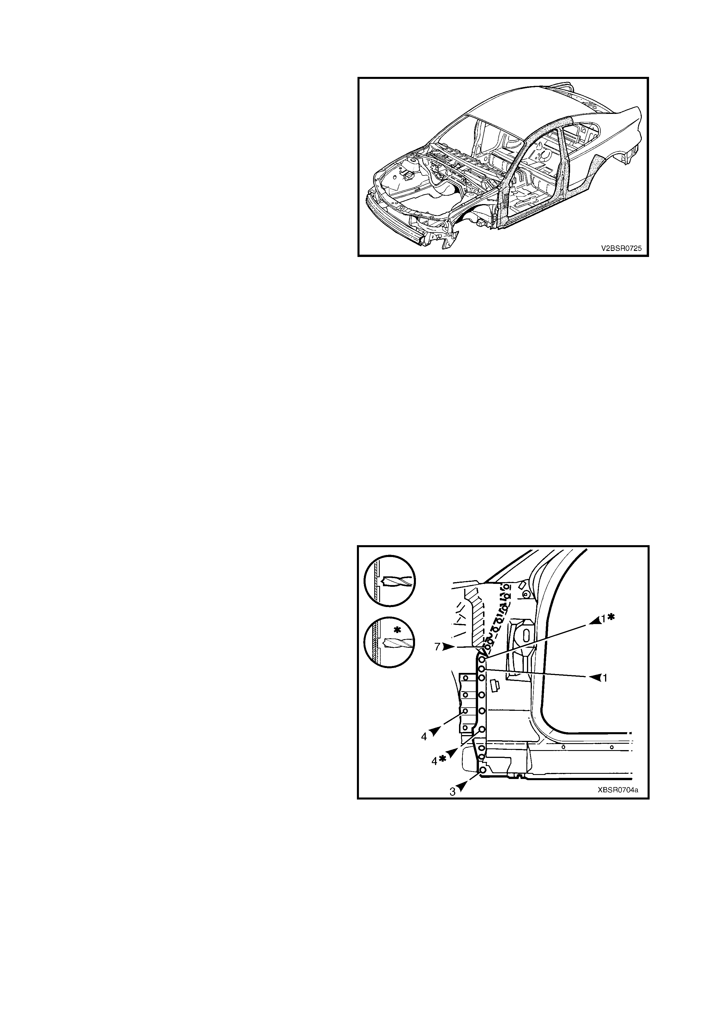
Figure 7D-26
7. Spot cut the welds attaching the door opening
frame assembly to the inner rocker panel and to
the hinge pillar inner panel assembly.
NOTE: In order to spot cut the uppermost of these
welds it may be necessary to cut and peel back the
section of hinge reinforcement panel covering the
welds, to gain the required access.
8. If required, spot cut the welds attaching the inner
rocker panel (1) and hinge pillar inner panel
assembly (2) to the rock er panel reinforcement (3) .
Refer to Figure 7D-28.
NOTE 1: Not all vehicles have these welds.
NOTE 2: The MIG welds should not have to be
removed.
Figure 7D-27
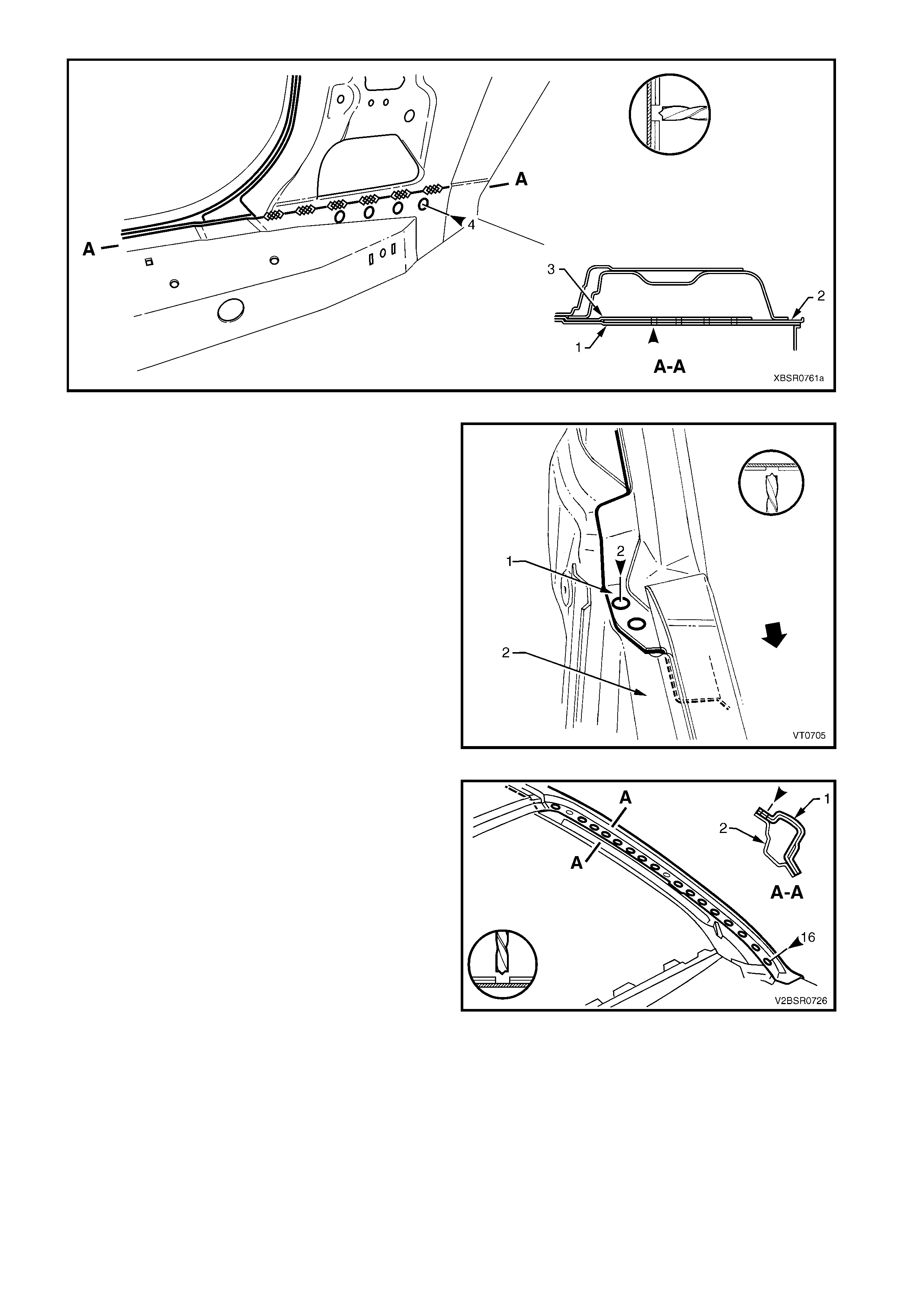
Figure 7D-28
9. Spot cut the two welds at the base of the hinge
pillar, attaching the door opening frame assembly
(1) to the hinge pillar inner panel assembly (2).
Figure 7D-29
10. Spot cut the welds on the windshield side flange,
attaching the door opening frame assembly (1) to
the hinge pillar inner panel assembly (2).
NOTE: There are several sub-assembly welds which
do not require removing.
11. Spot cut the welds on the flange surrounding the
front door opening, attaching the door opening
frame assembly to the hinge pillar inner panel
assembly, inner rocker panel and quarter panel
inner assembly, refer to Figure 7D-31.
Figure 7D-30
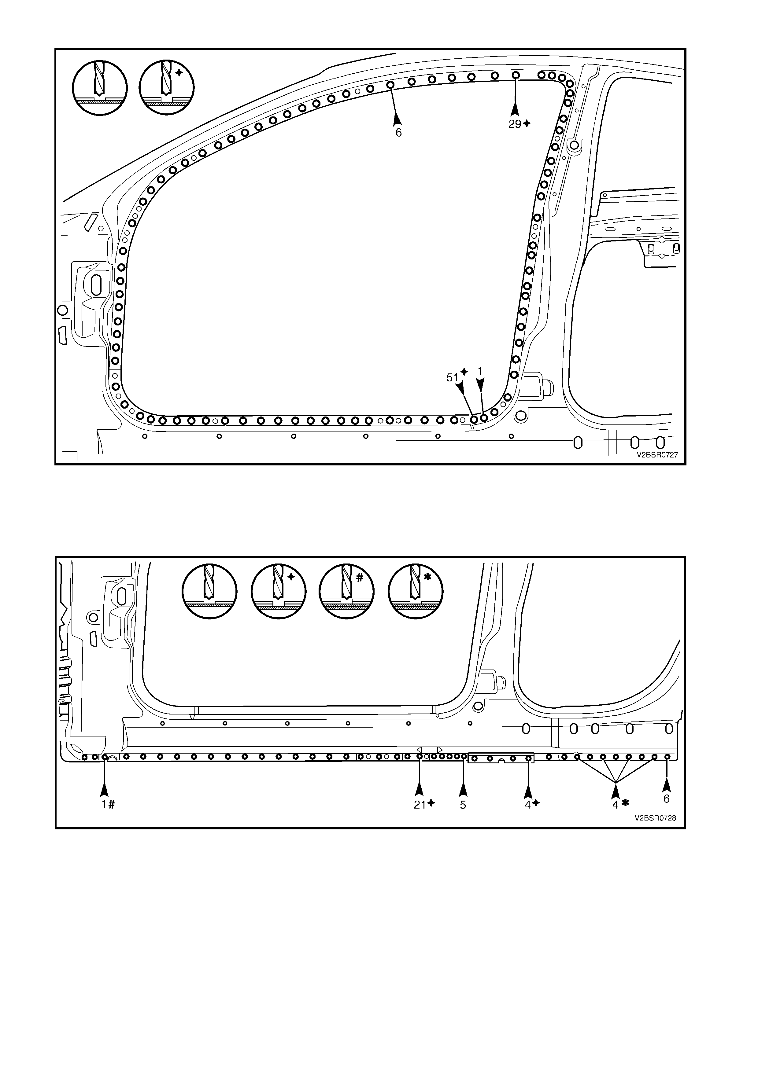
Figure 7D-31
12. Spot cut any remaining welds attaching the door opening frame assembly to the quarter panel inner
assembly around the rear wheel arch.
13. Spot cut along the vertic al f lange below the rock er panel to s eparate the door opening f ram e as sem bly from
the inner rocker panel. Refer to Figure 7D-32.
Figure 7D-32
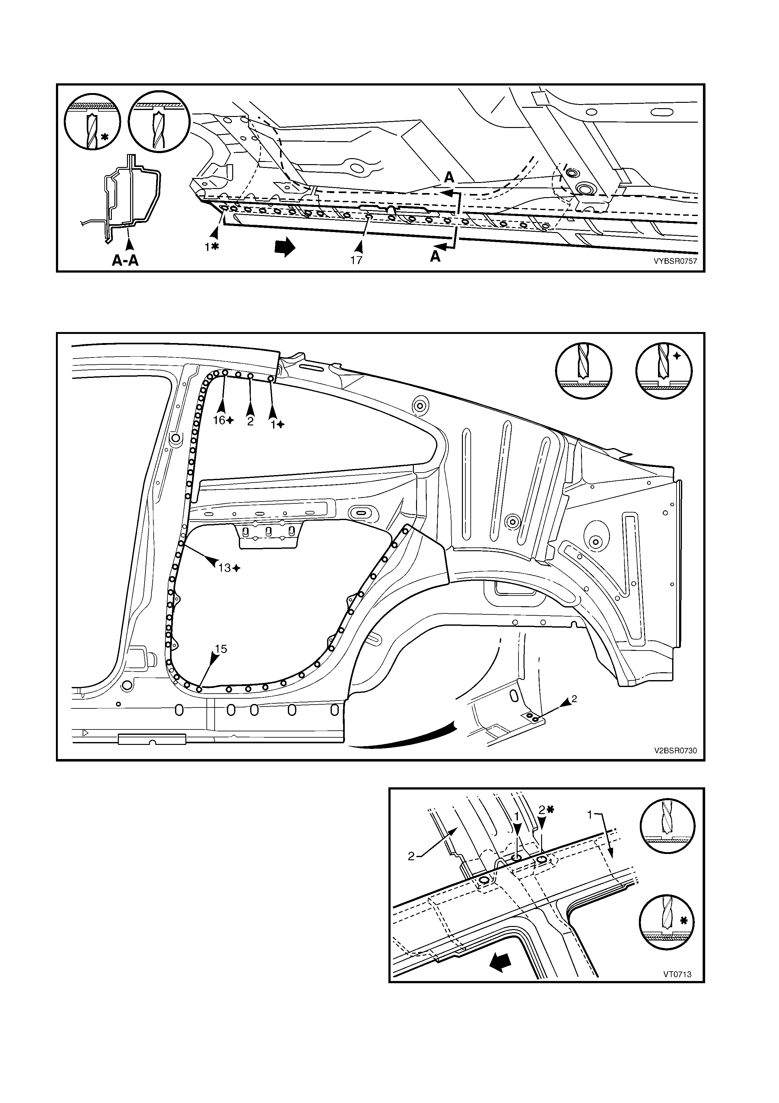
14. Spot cut from below, up into the rocker panel, the welds attaching the door opening frame assembly to the
quarter panel inner assembly. Refer to Figure 7D-33.
Figure 7D-33
15. Spot cut the welds attaching the door opening frame assembly to the quarter panel inner assembly, refer
Figure 7D-34.
Figure 7D-34
16. Spot cut the two welds attaching the roof bow
panel (2) to the centre pillar upper reinforcement,
and the s ingle weld attaching the roof bow panel to
the door opening frame assembly (1).
Figure 7D-35
17. Carefully lifting the roof bow panel out of the way,
spot cut the two welds attaching the centre pillar
upper reinforcement to the quarter panel inner
assem bly. The centre pillar upper reinf orcement is
removed as part of the door opening frame
assembly.
Figure 7D-36
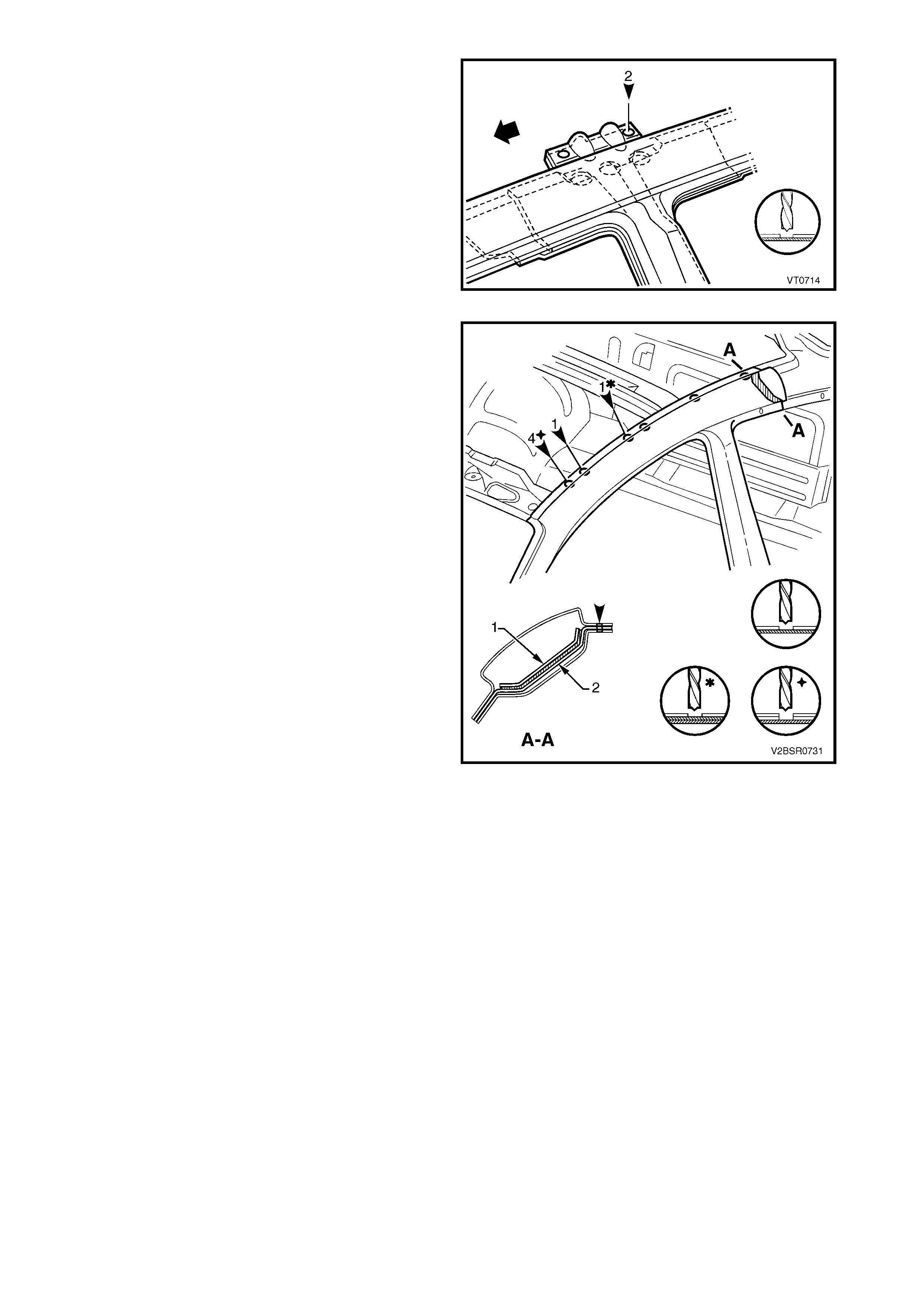
18. Spot cut the welds along the roof flange, attaching
the door opening frame assembly to the quarter
panel inner assembly.
NOTE: Also remove any remaining roof panel welds
as required.
19. Structural adhesive is applied within the join of the
centre pillar upper reinforcement (1) to the lock
pillar reinforcement (2). Cut back the rear section
of the outer panel and cut the centre pillar upper
reinforcement forward of the lock pillar
reinforcement. Remove the remaining section
once the frame assembly has been removed.
20. Remove the complete door opening frame
assembly and repair any damage to adjacent
parts.
21. Check and rectify the alignment of the body as
required, refer to 3. BODY DIMENSIONS in
Section 3D.
Figure 7D-37
REPLACE
NOTE 1: Spot welding is the preferred method for attaching of panels and should be used whenever possible.
Where the spot welding equipment will not access the required weld position, a plug weld should be performed.
NOTE 2: The same number and position of s pot welds ( or plug welds) s hould be used when replacing the panel,
as was used during manufacture, in order to maintain the original structural strength of the vehicle.
1. As required, mark the new panel with drilling locations in preparation for plug welding. Drill holes as required.
2. Prepare all mating surfaces and treat with Weld Through Primer (Item 1) as required, refer to
5. BODY SEALING, ADHESIVES & DEADENERS in Section 3D.
3. Apply Acrylic Spot Weld Sealer (Item 2), refer to 5. BODY SEALING, ADHESIVES & DEADENERS in
Section 3D.
4. Apply Structural Adhes ive (Item 6) to the r ear inner
side of the centre pillar upper reinfor cement f lange
(1), also ref er to 5. BODY SEALING, ADHESIVES
& DEADENERS in Section 3D.
Figure 7D-38
5. Securely clamp the door opening frame assembly
in position, ensuring the centre pillar upper
reinforcement (1) to lock pillar reinforcement (2)
join is seated correctly.
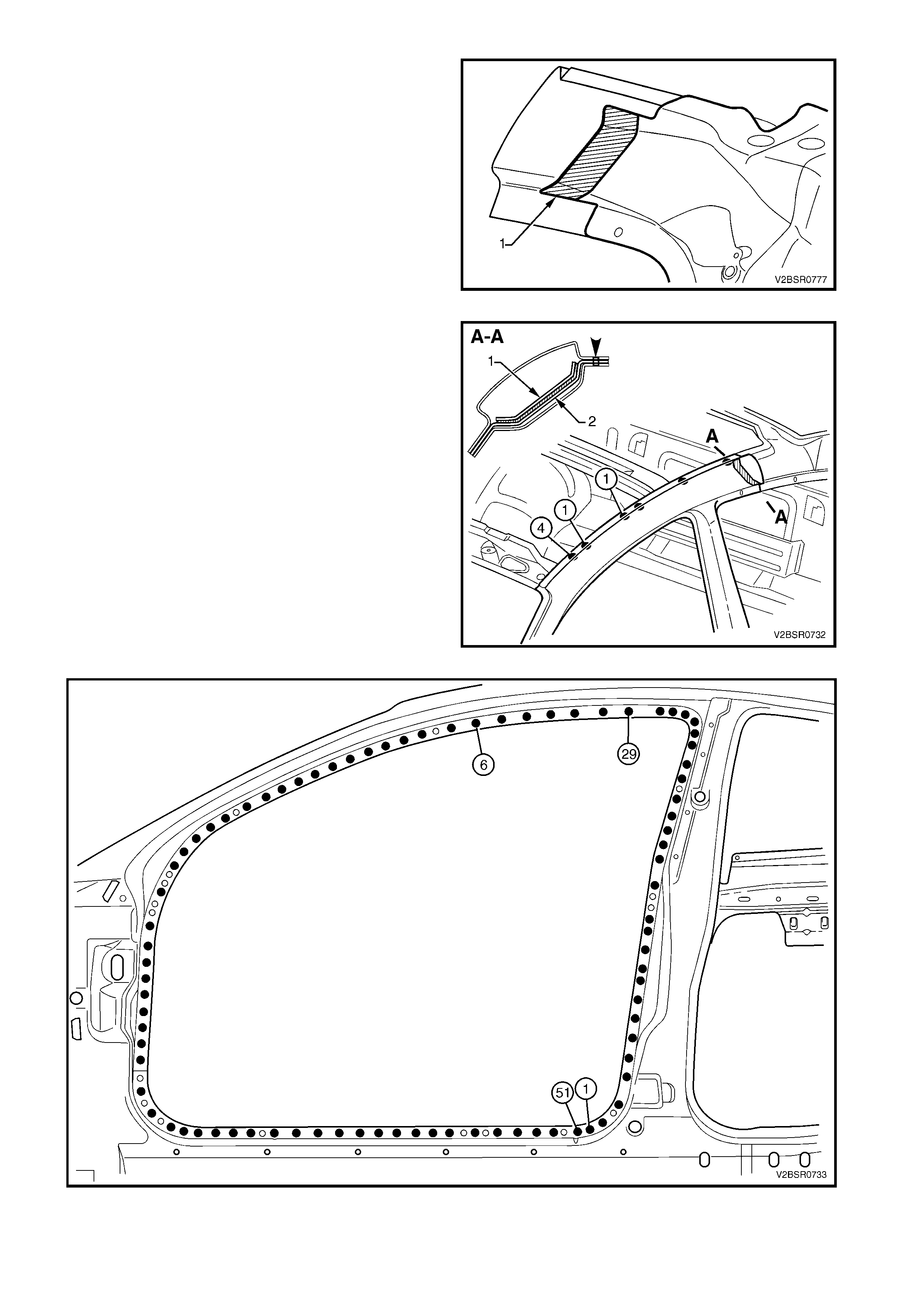
6. Spot or plug weld the door opening frame
assembly to the quarter inner panel assembly
along the roof panel flange. Complete this flange
when installing the roof panel.
7. Spot or plug weld the door opening frame
assembly to the quarter inner panel assembly
around the front door opening flange, refer to
Figure 7D-40.
Figure 7D-39
Figure 7D-40
8. Spot or plug weld the door opening fram e assem bly to the quarter inner panel ass embly, refer to Figure 7D-
41.
Figure 7D-41
9. Spot or plug weld the door opening frame
assembly (1) to the quarter inner panel assembly,
then spot or plug weld the roof bow panel (2) to the
door opening frame assembly as shown.
Figure 7D-42
10. Spot or plug weld along the windshield flange,
attaching the door opening frame assembly (1) to
the hinge pillar inner panel assembly (2).
Figure 7D-43
11. Spot or plug weld the door opening frame
assembly (1) to the hinge pillar inner panel
assembly (2) at the base of the hinge pillar.
Figure 7D-44
12. Spot or plug weld the door opening frame
assembly to the inner rocker panel and to the
hinge pillar inner panel assembly. If the sheet
metal was modified to allow access to these welds,
it should be repaired to its original configuration.
Figure 7D-45
13. If removed, plug weld the inner rocker panel and
hinge pillar inner panel assembly to the rocker
panel reinforcement.
14. Plug weld up through the rocker panel to attach
the door opening frame assembly to the quarter
panel inner assembly, refer to Figure 7D-47.
Figure 7D-46
Figure 7D-47
15. Spot or plug weld along the vertical flange below the rocker panel attaching the door opening frame
assembly to the inner rocker panel, refer to Figure 7D-48.
Figure 7D-48

16. Spot or plug weld two places, the door opening f rame as sem bly to the quarter panel inner assem bly ar ound
the rear wheel arch.
NOTE: This joint will be completed when the rear quarter panel is installed.
17. Replace front wheelhouse panel upper side rail, refer to Section 4, 2.5 FRONT WHEELHOUSE PANEL
UPPER SIDE RAIL FRONT END – REPLACE.
18. Replace the rear quarter panel, refer to 2.1 REAR QUARTER PANEL – REPLACE.
19. Replace the roof panel, refer to Section 9, ROOF.
NOTE: Refinish and prime any bare metal as required prior to replacing these panels.
20. Install the door hinges, refer to 2.3 DOOR HINGE (BODY SIDE) – REPLA CE in Section 8.
21. Refinish and paint panels and other components as required. Refer to Section 3, 1.3 PAINT REFINISHING.
22. Apply Joint Sealer (Item 3) as required. Refer to 5. BODY SEALING, ADHESIVES & DEADENERS in
Section 3D.
23. Apply Cavity W ax (Item 8) as required to the ins ide of any box s ections or areas inacces sible to paint, refer
6. CAVITY WAX in Section 3D.
24. Apply Spray-on Deadener (Item 7) where applicable, refer to 5. BODY SEALING, ADHESIVES &
DEADENERS in Section 3D.
25. Install the dash panel retaining bolt through the hinge pillar and tighten to the specified torque.
26. Replace the windshield and the quarter and rear window assemblies, refer to Section 1A6, STATIONARY
GLASS in the MY 2003 VY & V2 Series II Service Information.
27. Insert Cavity Foam into the hinge & centre pillars as required, refer to Section 2, 10. CAVITY FOAM.
28. Install the rem aining com ponents as described in the appr opriate Section of the MY 2003 VY & V2 Series II
Service Information.
DASH PANEL RETAINING BOLT
TORQUE SPECIFICATION 35.0 – 45.0 Nm
2.4 DOOR OPENING FRAME ASSEMBLY – PARTIAL REPLACE, HINGE PILLAR
NOTE: Cavity Foam is used within the hinge, centre
and lock pillar cavities . Care is r equired when repairing
the vehicle in these areas, refer to Section 2, 10.
CAVITY FOAM prior to beginning work for further
information.
REMOVE
1. Remove the adjacent bolt-on panels and
components as described in the appropriate
Section of the MY 2003 VY & V2 Series II Service
Information.
2. Secure an appropriate tool between the front door
opening flanges to maintain correct body
alignment.
3. Remove the windshield, refer to Section 1A6,
STATIONARY WINDOWS in the MY 2003 VY &
V2 Series II Service Information
4. Remove the dash panel retaining bolt from the
hinge pillar.
5. Remove the front wheelhouse panel upper side
rail, refer to Section 4. 2.5 FRONT
WHEELHOUSE PANEL UPPER SIDE RAIL.
Figure 7D-49
6. Spot cut the welds attaching the door opening
frame assembly to the inner rocker panel and to
the hinge pillar inner panel assembly.
NOTE: In order to spot cut the uppermost of these
welds it may be necessary to cut and peel back the
section of hinge reinforcement panel covering the
welds, to gain the required access.
7. If required, spot cut the welds attaching the inner
rocker panel (1) and hinge pillar inner panel
assembly (2) to the rock er panel reinforcement (3).
Refer to Figure 7D -51.
NOTE 1: Not all vehicles have these welds.
NOTE 2: The MIG welds should not have to be
removed.
Figure 7D-50
Figure 7D-51
8. Spot cut the two welds at the base of the hinge
pillar, attaching the door opening frame assembly
(1) to the hinge pillar inner panel assembly (2).
Figure 7D-52
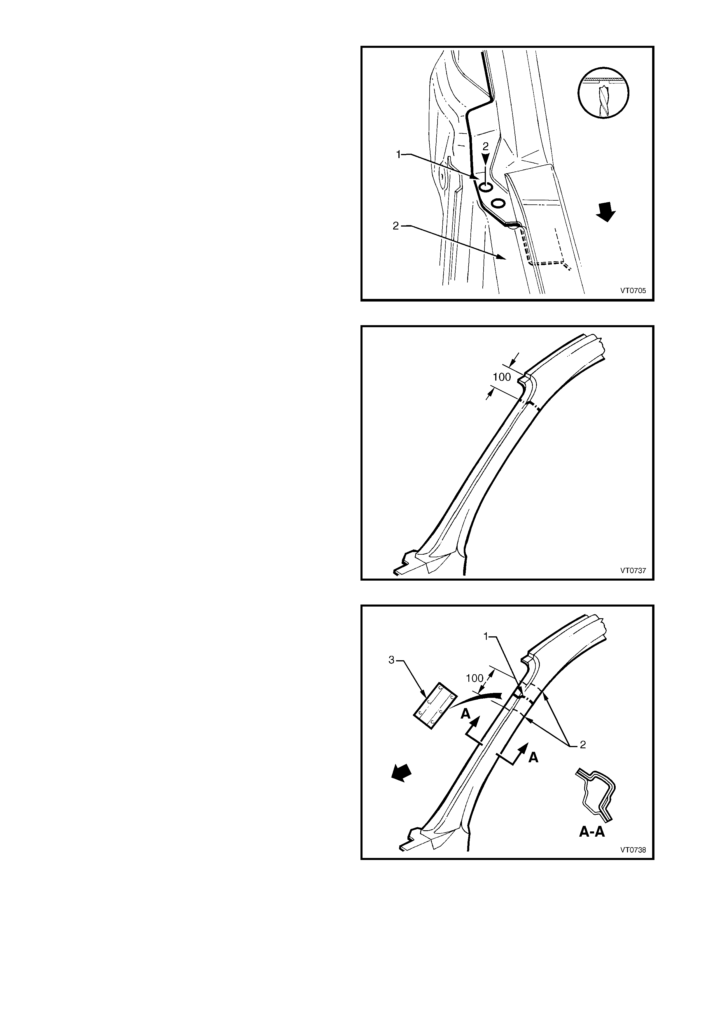
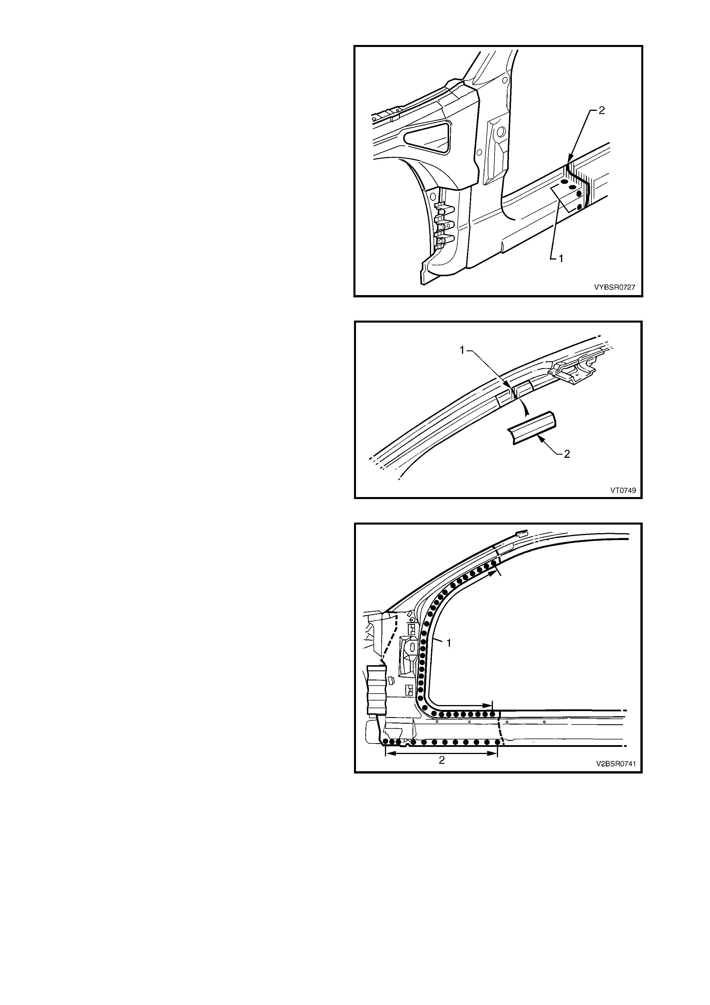
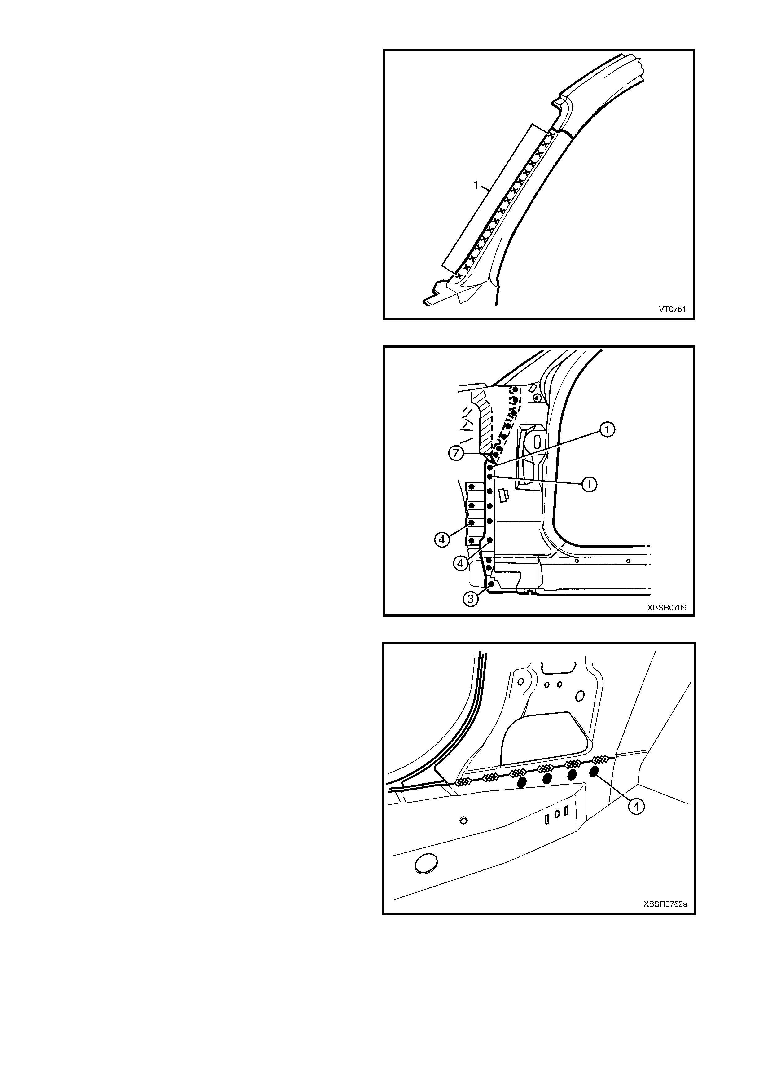
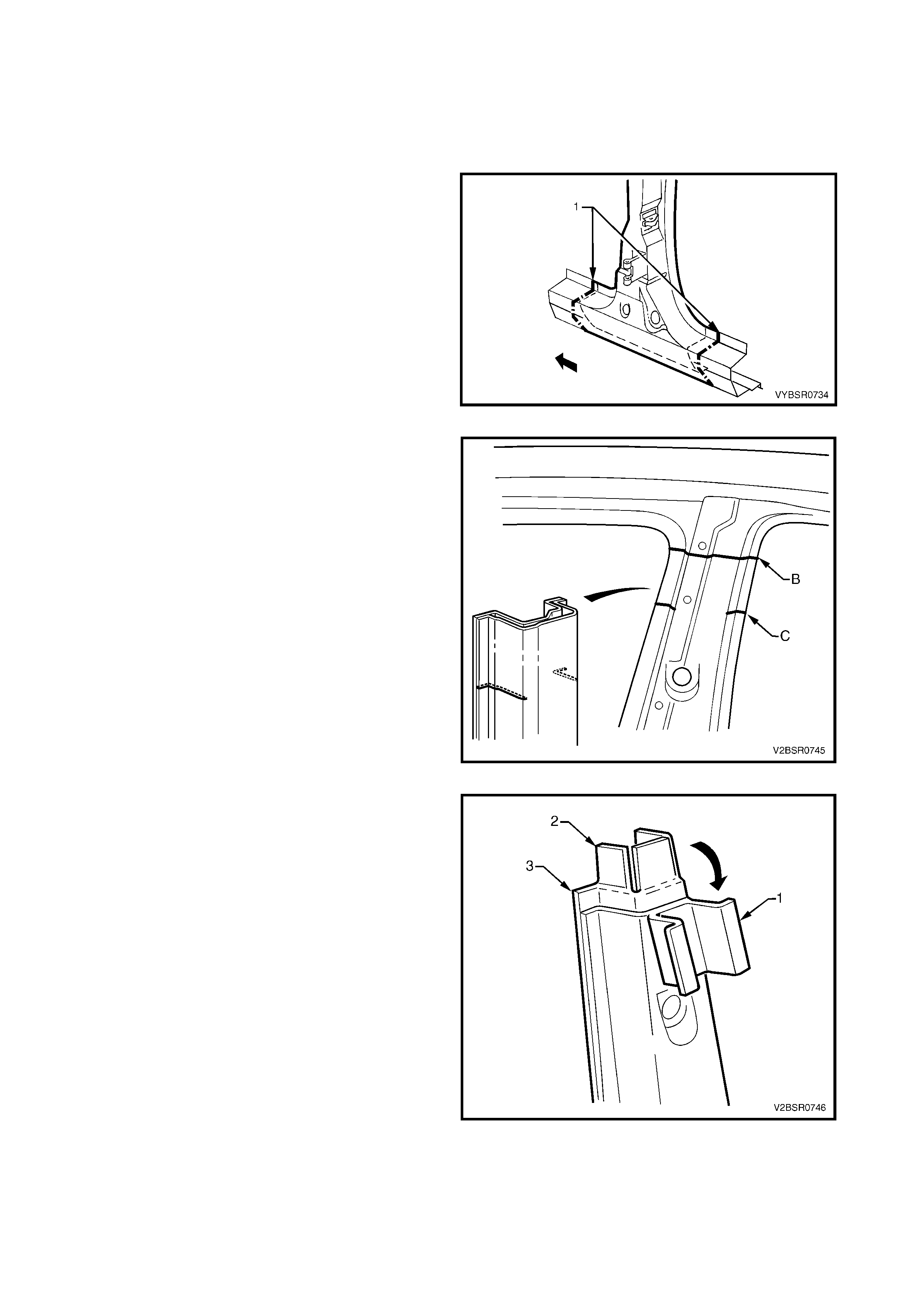
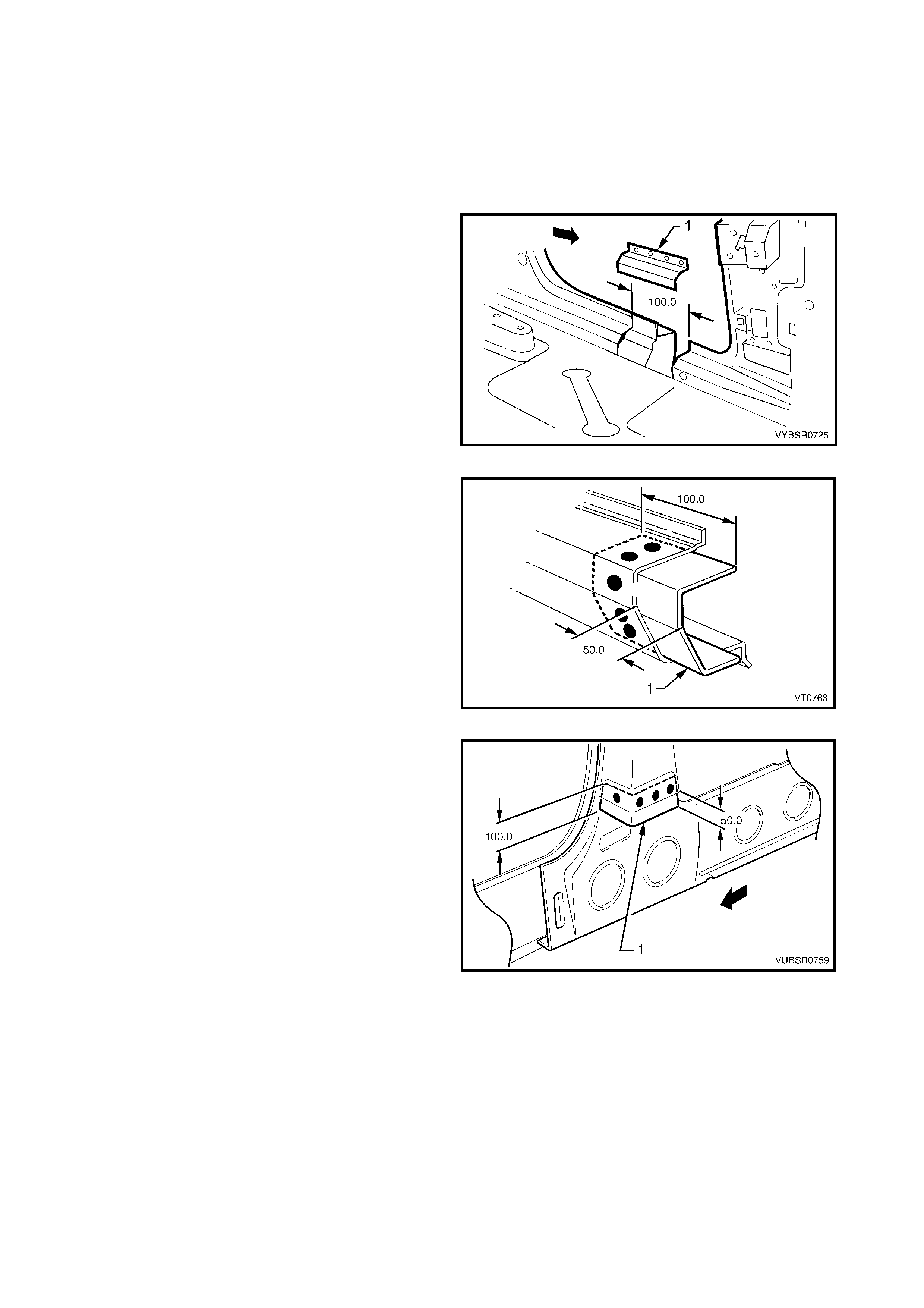
9. Select a cutting point on the hinge pillar
approximately 100 mm from the top of the
windshield flange.
Figure 7D-53
10. At the selected point (1), cut through the outer and
reinforcement panels, leaving the inner panel
intact.
11. Mark the inner panel at points 50 mm either side of
the cut line on the outer panel and cut the inner
panel at these two points (2). Spot cut the welds
and remove 100 mm section of inner panel (3).
Figure 7D-54
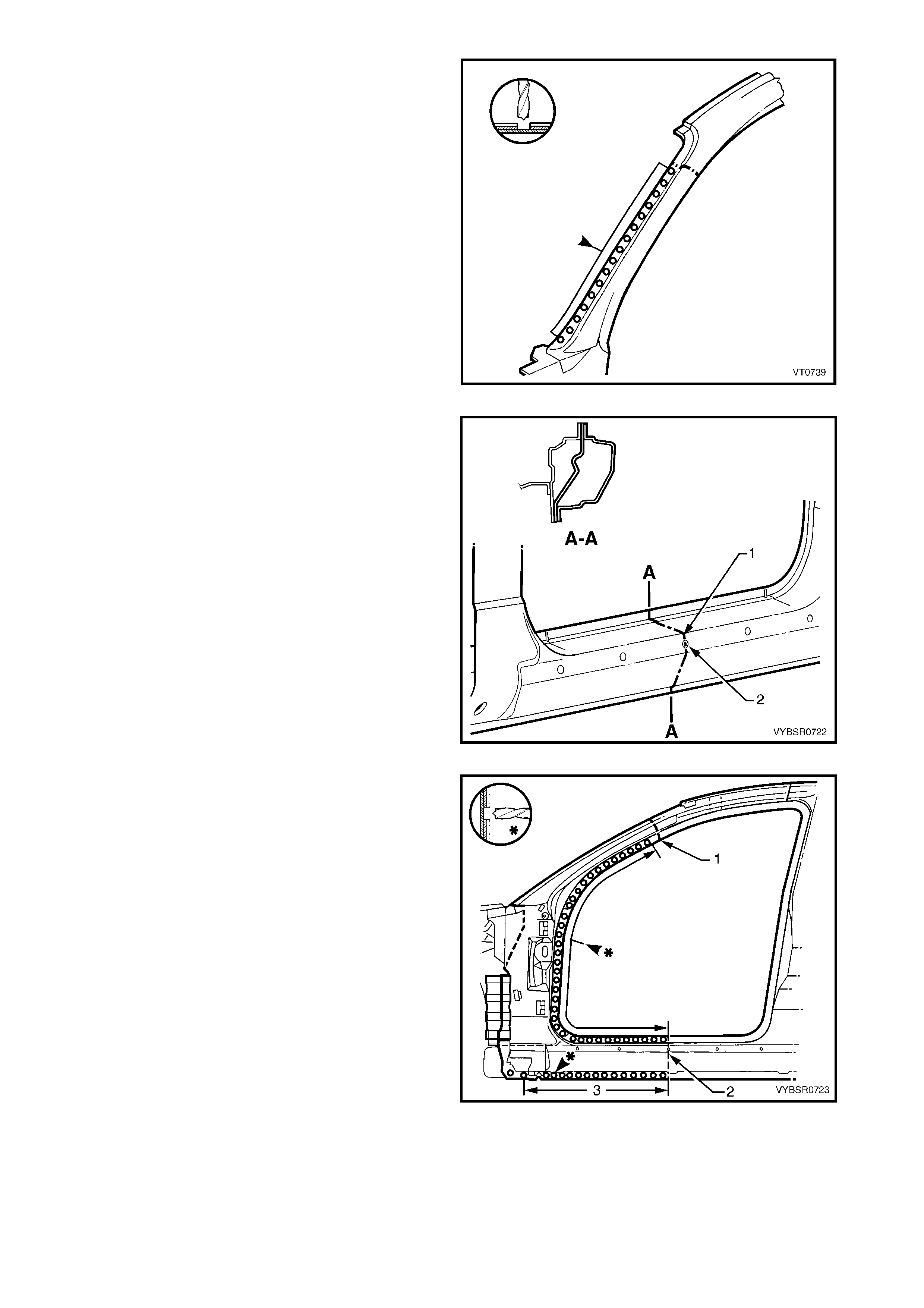
12. Spot cut the welds on the windshield side flange,
up to the point of the cut.
Figure 7D-55
13. Cut through the rocker panel section of the door
opening frame assembly. The cut point (1) should
be through the third rocker panel moulding
attaching hole (2). Cut through both the outer
panel and the reinforcement.
Figure 7D-56
14. Spot cut the welds on the flange along the front
door opening, from the cut near the top of the
hinge pillar (1) to the cut in the rocker panel (2).
15. Spot cut the welds along the flange (3) below the
rocker panel to the point of the cut.
16. Remove the partial hinge pillar from the vehicle,
then repair any damage to adjacent parts.
17. Check and rectify the alignment of the body as
required, refer to 3. BODY DIMENSIONS in
Section 3D.
Figure 7D-57
REPLACE
NOTE 1: Spot welding is the preferred method for attaching of panels and should be used whenever possible.
Where the spot welding equipment will not access the required weld position, a plug weld should be performed.
NOTE 2: The same number and position of s pot welds ( or plug welds) s hould be used when replacing the panel,
as was used during manufacture, in order to maintain the original structural strength of the vehicle.
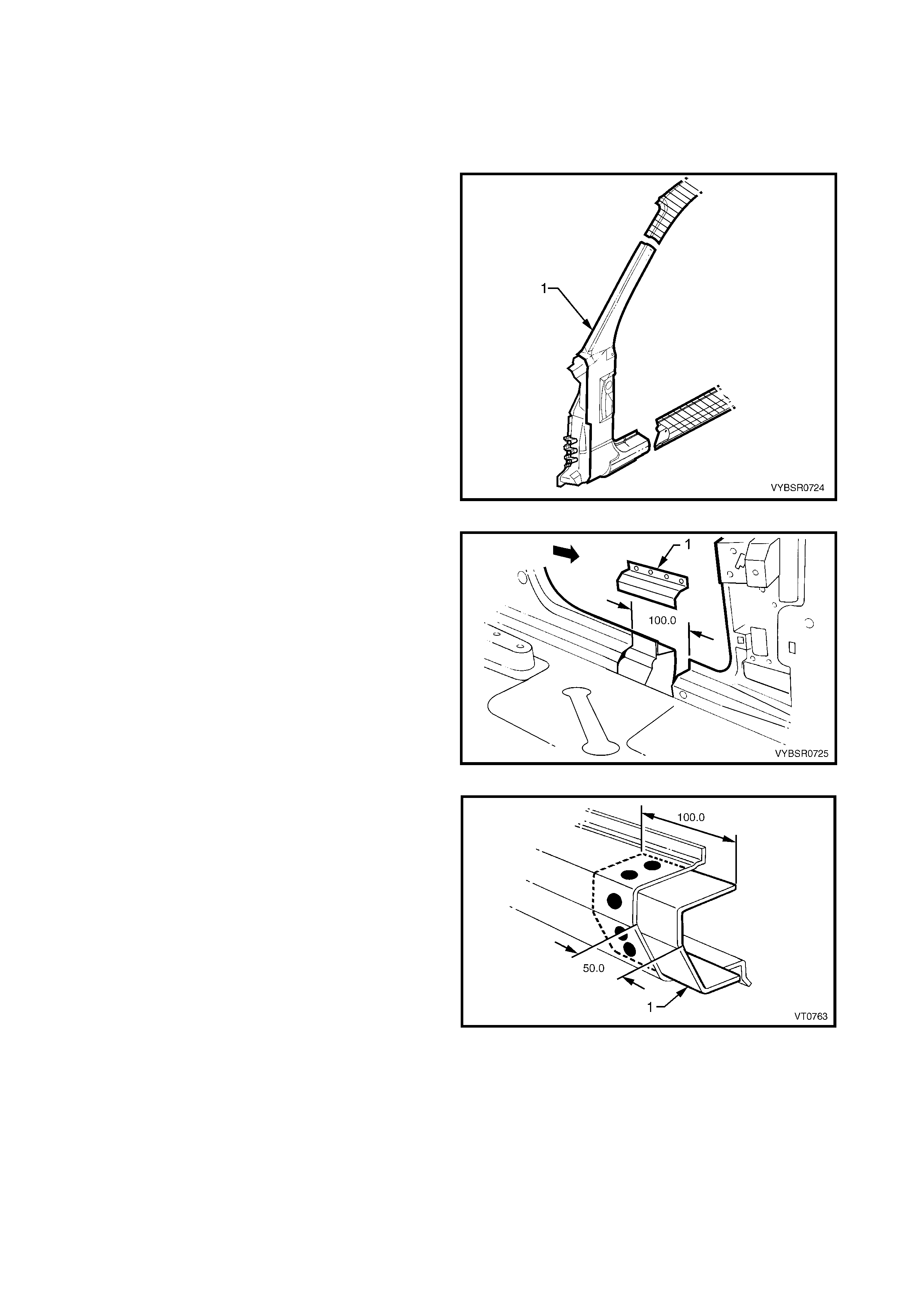
1. Cut a replacement panel section (1), accurately
measuring the position of cuts to match the section
removed.
Figure 7D-58
2. Remove a section of inner rocker panel (1). Cut
50 mm each side of the cut in the rocker panel.
This allows access for welding the rocker panel
reinforcement.
Figure 7D-59
3. Either manufacture a new section or cut an
existing length of surplus rocker panel section, to
form a reinforcement (1), approximately 100 mm in
length.
4. Prepare all mating surfaces and treat with Weld
Through Primer (Item 1) as required, refer to
5. BODY SEALING, ADHESIVES & DEADENERS
in Section 3D.
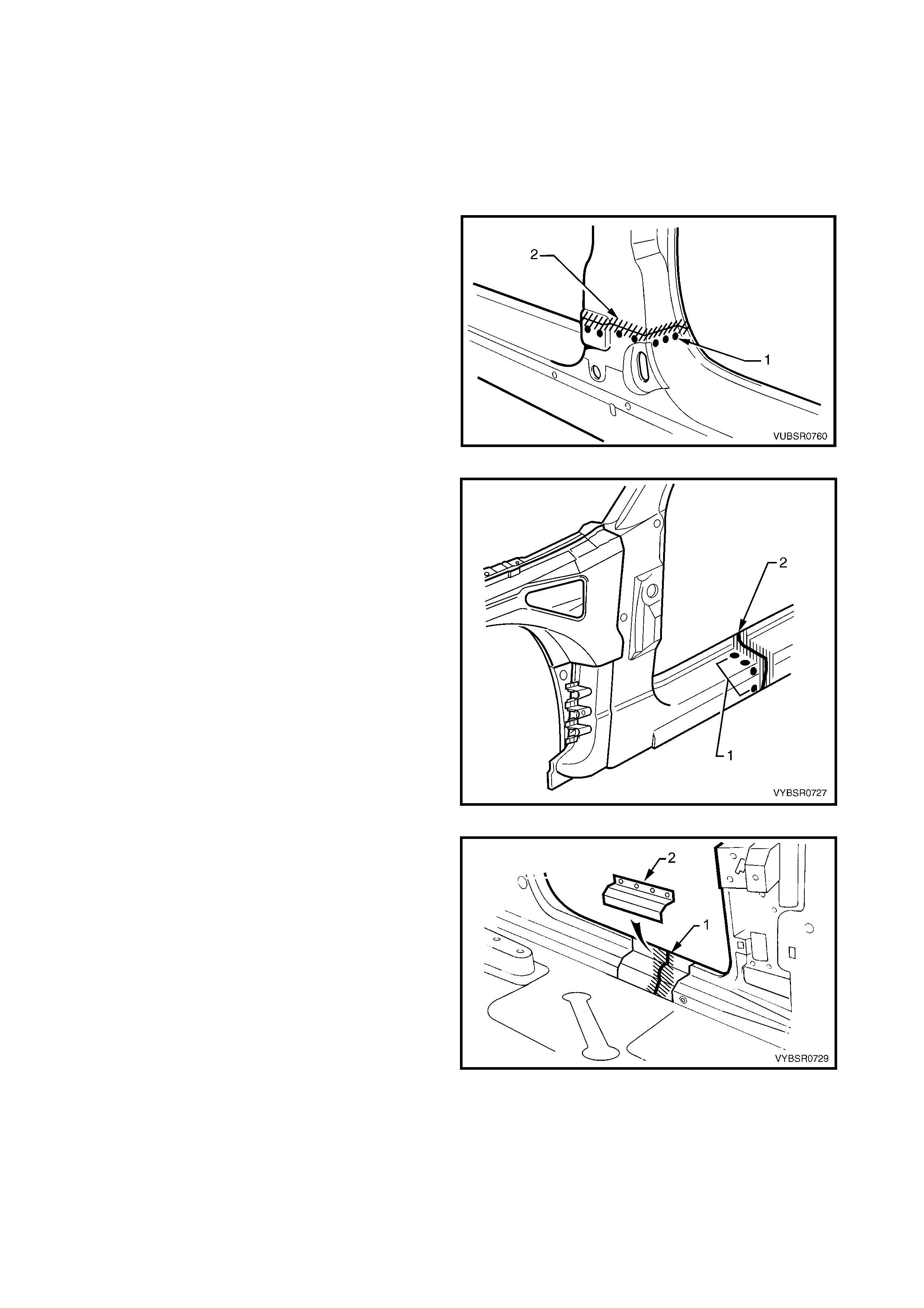
5. Clamp this reinforcement firmly behind the cut
section of rocker panel on the vehicle and spot or
plug weld in place. Position welds at a maximum
spacing of 35 mm apart.
Figure 7D-60
6. Using a similar technique, manufacture or cut a
section of reinforcement panel (1) approximately
60 mm long, to fit on the inside the outer panel of
the replacement hinge pillar (2) at the point of the
cut.
NOTE : Remove the flanges from this reinforcement
panel.
7. Prepare all mating surfaces and treat with Weld
Through Primer (Item 1) as required, refer to
5. BODY SEALING, ADHESIVES & DEADENERS
in Section 3D.
8. Clamp the reinforcement panel firmly behind the
outer panel of the cut section of the hinge pillar
and spot weld (3) in place.
9. Mark the new hinge pillar with drilling locations in
preparation for plug welding where required. Drill
holes as marked.
10. Prepare all mating surfaces and treat with Weld
Through Primer (Item 1) as required, refer to
5. BODY SEALING, ADHESIVES & DEADENERS
in Section 3D.
11. Apply Cavity Wax (Item 8) as r equired to the inside
of any box sections or areas inaccessible to paint,
refer 6. CAVITY WAX in Section 3D.
Figure 7D-61
12. Clamp the replacem ent panel (1) in position on the
vehicle and check the door opening dimensions.
Refer to 3. BODY DIMENSIONS in Section 3D.
Adjust position as required.
Figure 7D-62
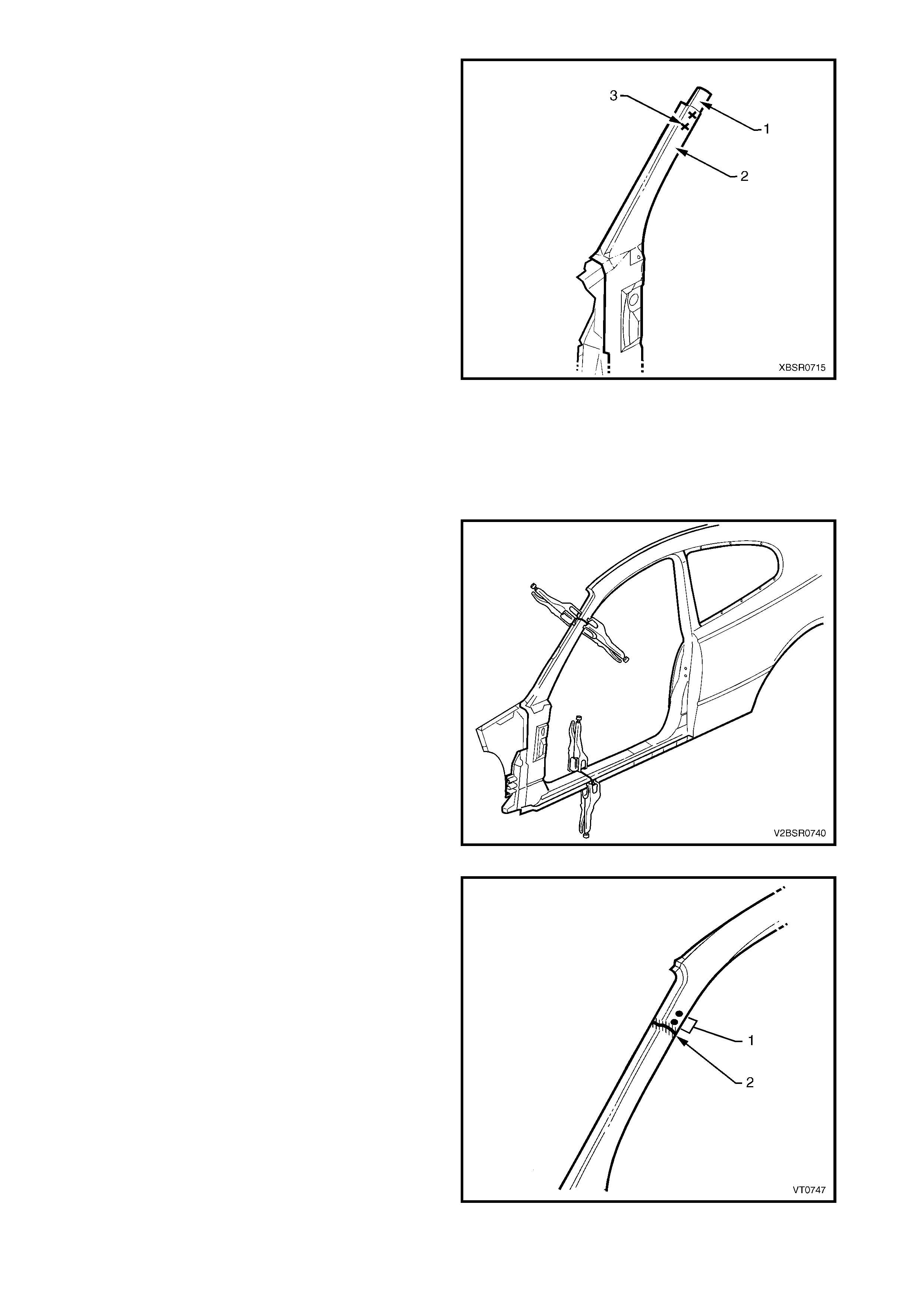
13. Plug weld (1) the top of the pillar to the
manufactured reinforcement, then MIG butt
weld (2) the two sections together.
Figure 7D-63
14. Plug weld (1) the new panel in the rocker panel
region, then MIG butt weld (2) the two sections
together.
Figure 7D-64
15. Gaining access through the removed section of
inner panel, MIG butt weld (1) the reinforcement
panels together.
16. Butt weld the removed access panel (2) in
position. Replace the spot welds with the same
number that was removed.
Figure 7D-65
17. Spot weld (1) the hinge pillar section along the
door opening flange.
18. Spot weld (2) the flange beneath the rocker panel,
attaching the new panel to the inner rocker panel.
Figure 7D-66
19. Spot weld (1) the hinge pillar section along the
windshield opening flange.
Figure 7D-67
20. Spot or plug weld the door opening frame
assembly to the inner rocker panel and to the
hinge pillar inner panel assembly. If the sheet
metal was modified to allow access to these welds,
it should be repaired to its original configuration.
Figure 7D-68
21. If removed, plug weld the inner rocker panel and
hinge pillar inner panel assembly to the rocker
panel reinforcement.
Figure 7D-69
22. Gaining access through the section of removed
inner rocker panel, MIG butt weld (1) the new
section of rocker panel reinforcement to the
existing section.
23. Replac e the rem oved section of inner r ock er panel
(2) by MIG butt welding it in place and spot welding
it along the door opening flange. Replace the spot
welds with the same number of as were cut out.
24. Dress the butt welds by grinding or sanding,
ensuring sufficient material remains to guarantee
the strength of the weld.
25. Install the door hinges, refer to 2.3 DOOR HINGE
(BODY SIDE) – REPLACE in Section 8.
26. Refinish and paint panels and other components
as required. Refer to Section 3, 1.3 PAINT
REFINISHING.
27. Apply Joint Sealer (Item 3) as required. Refer to
5. BODY SEALING, ADHESIVES & DEADENERS
in Section 3D.
Figure 7D-70
28. Apply Cavity W ax (Item 8) as required to the ins ide of any box s ections or areas inacces sible to paint, refer
6. CAVITY WAX in Section 3D.
29. Install the dash panel bolt through the hinge pillar and tighten to the specified torque.
30. Replace the windshield, refer to Section 1A6, STATIONARY GLASS in the MY 2003 VY & V2 Series II
Service Information.
31. Insert Cavity Foam into the hinge pillar as required, refer to Section 2, 10. CAVITY FOAM.
32. Install the rem aining com ponents as described in the appr opriate Section of the MY 2003 VY & V2 Series II
Service Information.
DASH PANEL RETAINING BOLT
TORQUE SPECIFICATION 35.0 – 45.0 Nm
2.5 DOOR OPENING FRAME ASSEMBLY – PARTIAL REPLACE, CENTRE PILLAR
NOTE: Cavity Foam is used within the hinge, centre
and lock pillar cavities . Care is r equired when repairing
the vehicle in these areas, refer to Section 2, 10.
CAVITY FOAM prior to beginning work for further
information.
REMOVE
1. Remove the adjacent bolt-on panels and
components as described in the appropriate
Section of the MY 2003 VY & V2 Series II Service
Information.
2. Install the vehicle on a suitable fixture. As a
minimum, support the appropriate structural
sections of the vehicle on safety stands. Secure a
suitable tool between the front door opening
flanges to maintain alignment.
3. Rem ove the rear quarter panel, refer to 2.1 REAR
QUARTER PANEL – REPLACE.
Figure 7D-71
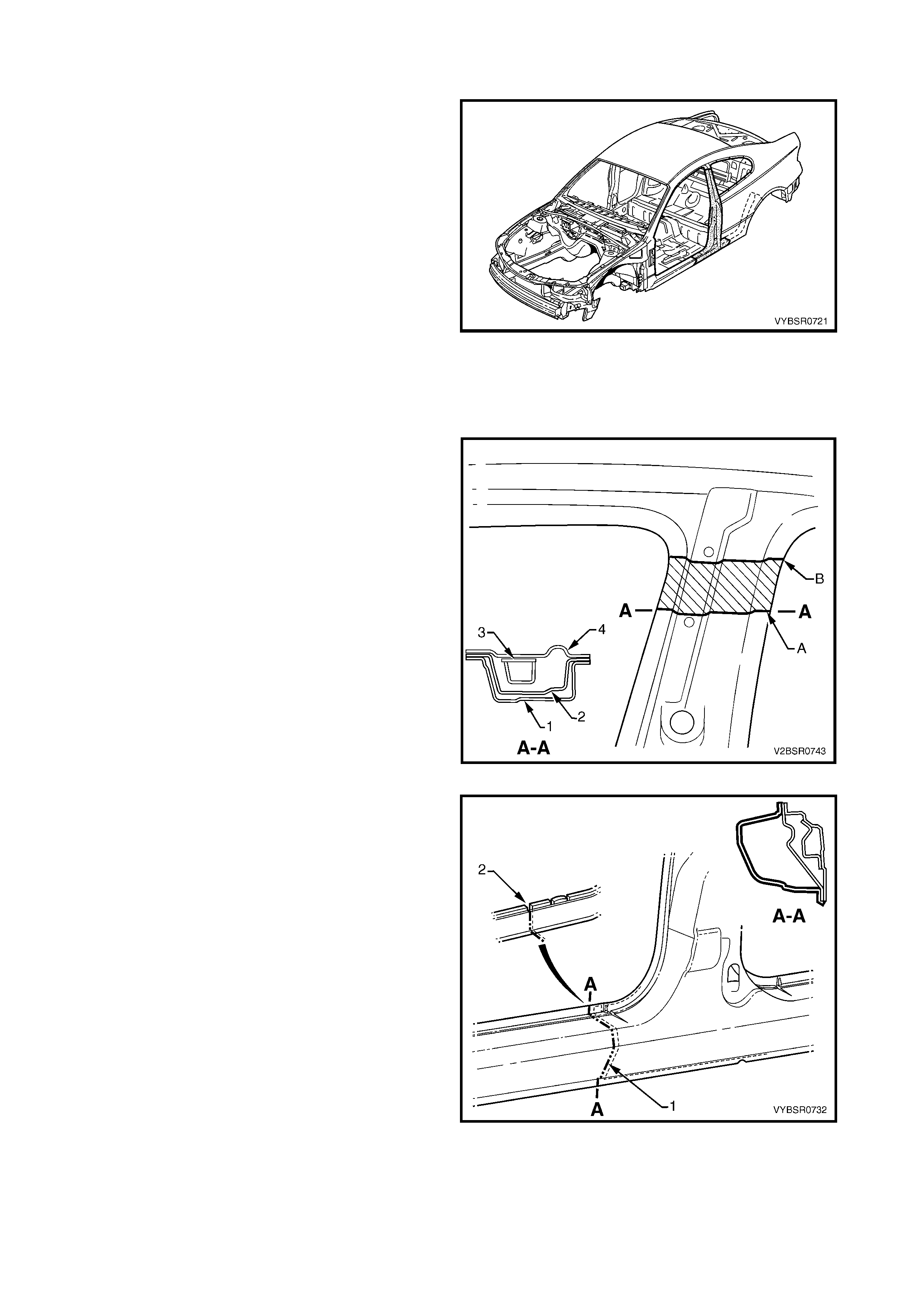
4. Cut the door opening frame assembly (1) and
centre pillar reinforcement (2) at point A as shown.
NOTE: Do not cut through the centre pillar inner
reinforcement (3) or quarter panel inner assembly (4).
5. Make a second cut through the door opening
frame assembly (1) ONLY at point B as shown.
6. Spot cut the welds between the two cuts and
remove the shaded section of the door opening
frame assembly.
Figure 7D-72
7. Cut through the door opening frame assembly (1)
at the join of the rocker panel reinforcement and
centre pillar reinforcement (2).
NOTE: Make the cut carefully as the rocker panel
reinforcement must not be cut. The centre pillar
reinforcement is removed with the centre pillar section.
Figure 7D-73
8. Cut through the door opening frame assembly (1)
rearward of the dimple (2) in the flange.
NOTE: Make the cut carefully as the quarter panel
inner assembly must not be cut.
Figure 7D-74
9. Spot cut the welds attac hing the underbody jac king
locator (1) and remove.
10. Spot cut the welds on the flange attaching the
centre pillar section to the inner rocker panel (6).
Refer to weld group A.
11. Spot cut the welds on the underside of the rocker
panel attaching the centre pillar section to the
quarter panel inner assembly (7). Refer to weld
group B.
Figure 7D-75
12. Spot cut the welds on the door opening frame
flanges both sides of the centre pillar and remove
the centre pillar section from the vehicle.
13. Repair any damage to surrounding area as
required.
Figure 7D-76
REPLACE
NOTE 1: Spot welding is the preferred method for attaching of panels and should be used whenever possible.
Where the spot welding equipment will not access the required weld position, a plug weld should be performed.
NOTE 2: The same number and position of s pot welds ( or plug welds) s hould be used when replacing the panel,
as was used during manufacture, in order to maintain the original structural strength of the vehicle.
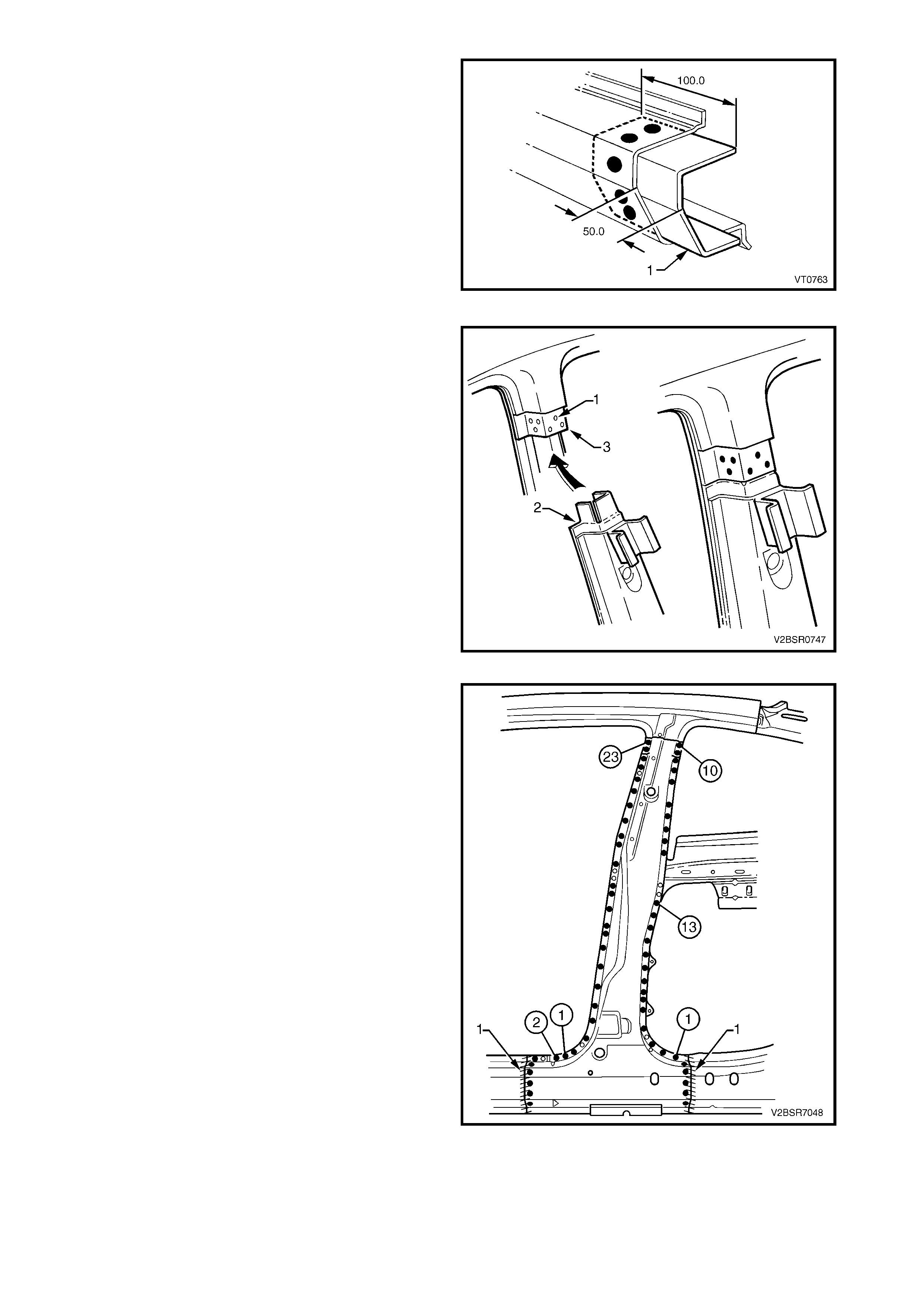
1. Cut the replacement panel through the rocker
section as shown. Accur ately measure the position
of cuts to match the removed panel section.
Figure 7D-77
2. At point B, cut the replacement panel completely
through.
NOTE: This point matches point B on the remaining
section on the vehicle.
3. At point C, cut along each s ide of the door opening
frame (outer panel) ONLY.
NOTE 1: Do not cut through the front face of the door
opening frame and do not cut the reinforcement.
NOTE 2: T his point is approxim ately 10–15 m m below
point A on the remaining section on the vehicle.
Figure 7D-78
4. On the replacement panel, bend back the outer
skin (1). This will expose the reinforcement which
is to be cut down each corner (2).
5. Remove the front and rear flanges (3) which will
align at point A on the remaining section on the
vehicle.
6. Form a joggle on each of the faces to enable the
replacement reinforcement to fit behind the
remaining section on the vehicle.
Figure 7D-79
7. Cut two sections from surplus rocker panel
pieces, or manufacture new sections (1), each
approximately 100 mm in length.
8. Prepare all mating surfaces and treat with Weld
Through Primer (Item 1) as required, refer to
5. BODY SEALING, ADHESIVES & DEADENERS
in Section 3D.
9. Clamp these sections firmly behind both the cut
faces of rocker panel on the vehicle and spot or
plug weld in place. Perform the welds at a
maximum spacing of 35 mm.
10. Mark the new panel with drilling locations in
preparation for plug welding where required. Drill
holes as marked.
Figure 7D-80
11. Drill three holes (1) on each face of the
reinforcement on the vehicle to facilitate plug
welding.
12. Prepare all mating surfaces and treat with Weld
Through Primer (Item 1) as required, refer to
5. BODY SEALING, ADHESIVES & DEADENERS
in Section 3D.
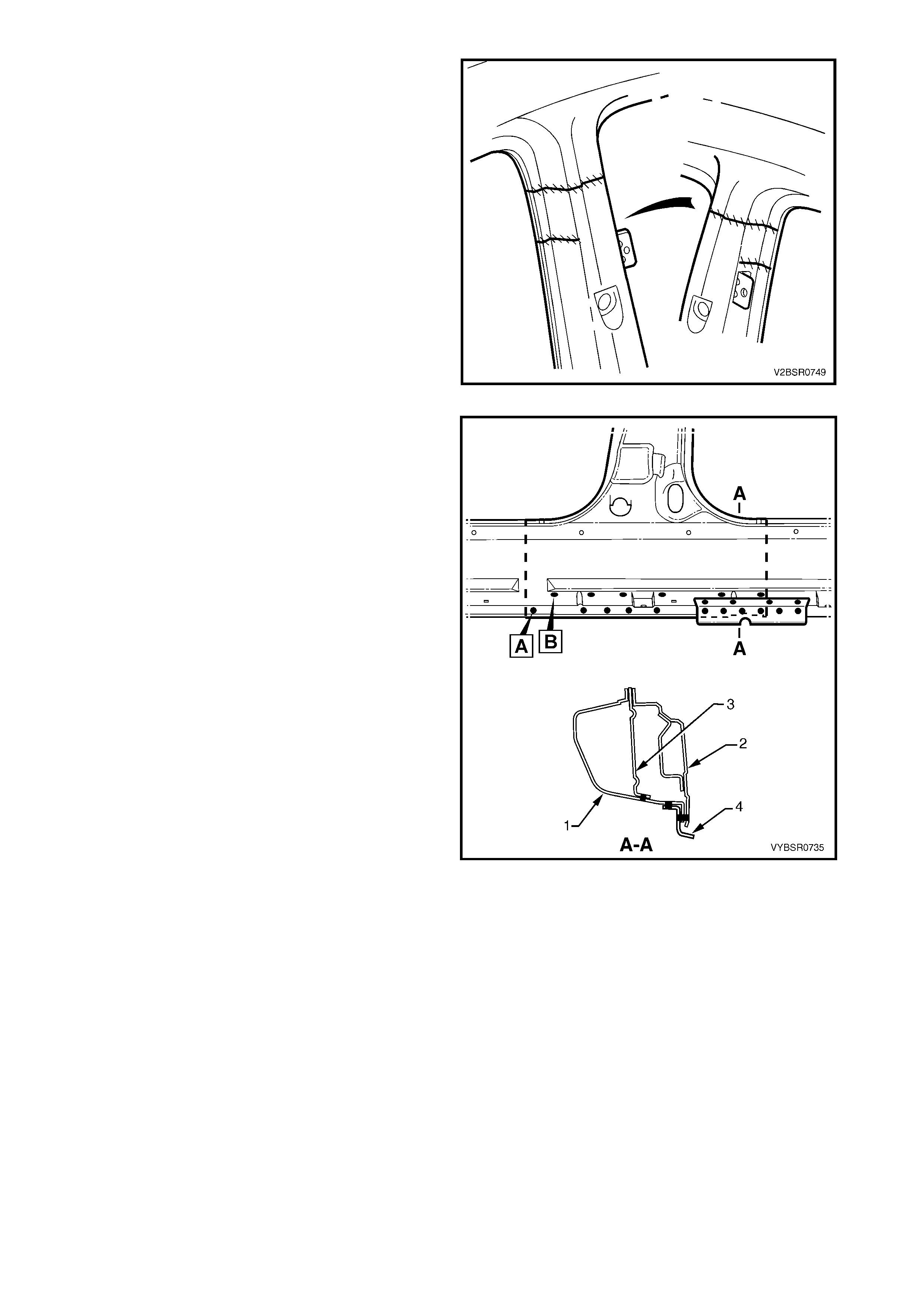
13. Install the replacement panel in position, sliding the
tongue of the centr e pillar reinf or c ement (2) behind
the upper section of the reinforcement (3).
NOTE: Manipulate the rock er panel section in position,
inserting the front first, then the rear.
14. Clamp the assembly in place and plug weld the
centre pillar reinforcement at the upper join.
Figure 7D-81
15. Close over the outer panel flap.
16. Spot weld along the flanges on both sides of the
centre pillar.
17. Plug weld the rocker panel section to the
reinforcement sections.
18. MIG butt weld the rocker panel joins (1).
Figure 7D-82
19. MIG butt weld the centre pillar joins.
Figure 7D-83
20. Plug weld the flange attaching the centre pillar
section (1) to the inner rocker panel (2). Refer weld
group A.
21. Plug weld on the underside of the rock er panel the
centre pillar section to the quarter panel inner
assembly (3). Refer weld group B.
22. Plug weld the underbody jacking locator (4) in
place.
23. Install the door hinge, refer to 2.3 DOOR HINGE
(BODY SIDE) – REPLACE in Section 8.
24. Dress the welds by grinding or sanding, ensuring
sufficient material remains to guarantee the
strength of the weld. Finish the area using an
appropriate technique.
25. Prim e any bare metal areas as required and install
the rear quarter panel, refer to 2.1 REAR
QUARTER PANEL – REPLACE.
26. Refinish and paint panels and other components
as required. Refer to Section 3, 1.3 PAINT
REFINISHING.
27. Apply Joint Sealer (Item 3) as required. Refer to
5. BODY SEALING, ADHESIVES & DEADENERS
in Section 3D.
28. Apply Cavity Wax (Item 8) as r equired to the inside
of any box sections or areas inaccessible to paint,
refer 6. CAVITY WAX in Section 3D.
29. Insert Cavity Foam into the centre pillar as
required, refer to Section 2, 10. CAVITY FOAM.
30. Install the remaining components as described in
the appropriate Section of the MY 2003 VY & V2
Series II Service Information.
Figure 7D-84
2.6 DOOR OPENING FRAME ASSEMBLY – PARTIAL REPLACE, ROCKER PANEL
IMPORTANT: This procedure details the replacement
of the rocker panel section of the door opening frame
assembly.
As there are several critical reinforcements in the lower
hinge pillar area, the rock er panel section must not be
cut forward of the area shown. If the rocker panel is
damaged forward of this ar ea, replac e the rock er panel
and partial hinge pillar as one section. Modify this
procedure accordingly, also referring to 2.4 DOOR
OPENING FRAME ASSEMBLY – PARTIAL
REPLACE, HINGE PILLAR.
REMOVE
1. Remove the adjacent bolt-on panels and
components as described in the appropriate
Section of the MY 2003 VY & V2 Series II Service
Information.
2. Rem ove the rear quarter panel, refer to 2.1 REAR
QUARTER PANEL – REPLACE.
3. Secure the vehicle on a suitable fixture. As a
minimum, support the appropriate structural
sections of the vehicle on safety stands. Install
suitable bracing in the vehicle to ensure that the
correct body alignment is maintained when the
rocker panel section is removed.
Figure 7D-85
4. Cut through the rocker panel section of the door
opening frame assembly. The cut point (1) must
not be further forward than the third rocker panel
moulding attaching hole (2). Cut through both the
outer panel and the reinforcement.
Figure 7D-86
5. Using a suitable cutting tool, cut through the door
opening frame assembly (1), including the centre
pillar reinforcement (2), near the base of the centre
pillar.
Figure 7D-87
6. If required, select a cutting point through the door
opening frame assembly, rearward of point (1). Cut
through the door opening frame assembly (2) only.
NOTE: It may be preferable to remove the complete
rear section.
7. Depending on the cut location, spot cut any
remaining welds attaching the door opening frame
assembly to the quarter panel inner assembly
around the rear wheel arch.
8. Spot cut the welds attaching the rocker panel
section to the quarter panel inner assembly as
required. Refer to Figure 7D-89.
Figure 7D-88
Figure 7D-89
9. Spot cut along the flanges around the door opening frame assembly as required, to separate the rocker
panel section from the inner rocker panel and quarter panel inner assembly, refer to Figure 7D-90.
Figure 7D-90
10. Remove the rocker panel section from the vehicle and then repair any damage to adjacent parts as required.
11. Check and rectify the alignment of the body as required, refer to 3. BODY DIMENSIONS in Section 3D.
REPLACE
NOTE 1: Spot welding is the preferred method for attaching of panels and should be used whenever possible.
Where the spot welding equipment will not access the required weld position, a plug weld should be performed.
NOTE 2: The same number and position of s pot welds ( or plug welds) s hould be used when replacing the panel,
as was used during manufacture, in order to maintain the original structural strength of the vehicle.
1. Cut a replacement rocker panel section from a new door opening frame assembly. Accurately measure the
position of the cuts on the removed section.
2. Remove a section of inner rocker panel (1). Cut
50 mm each side of the cut in the rocker panel.
This allows access for welding the rocker panel
reinforcement.
Figure 7D-91
3. Either manufacture a new section or cut an
existing length of surplus rocker panel section, to
form a reinforcement (1), approximately 100 mm in
length.
4. Prepare all mating surfaces and treat with Weld
Through Primer (Item 1) as required, refer to
5. BODY SEALING, ADHESIVES & DEADENERS
in Section 3D.
5. Clamp this reinforcement firmly behind the cut
section of rocker panel on the vehicle and spot or
plug weld in place. Position welds at a maximum
spacing of 35 mm apart.
Figure 7D-92
6. Manufacture or cut a reinforcement (1),
approximately 100 mm long, to fit inside of the
existing B-pillar section at the point of the cut.
7. Prepare all mating surfaces and treat with Weld
Through Primer (Item 1) as required, refer to
5. BODY SEALING, ADHESIVES & DEADENERS
in Section 3D.
8. Clamp the manufactured reinforcement panel
firmly to the inside of the outer panel of the door
opening frame assembly on the vehicle and plug
weld in position. Position welds at a maximum
spacing of 35 mm.
9. Mark the replacement rocker panel section with
drilling positions in preparation for plug welding as
required.
NOTE: The outer panel will be plug welded from the
outer side of the vehicle, while the rocker panel and
centre pillar reinforcements will be butt welded from
the inner side of the vehicle.
Figure 7D-93
10. Prepare all mating surfaces and treat with Weld
Through Primer (Item 1) as required, refer to
5. BODY SEALING, ADHESIVES & DEAD ENERS
in Section 3D.
11. Install the replacement section onto the vehicle by
sliding the front and centre pillar sections onto the
reinforcements, while lifting the rear into position.
12. Clamp the panel in position.
13. Weld the new rocker panel section in position by
plug welding (1) to the reinforcement.
14. MIG butt weld the reinforcement panel from inside
the centre pillar, thr ough the large hole in the inner
panel immediately behind the weld.
15. Finish the centre pillar attachment by MIG
welding (2) along the join of the outer panel.
Figure 7D-94
16. Plug weld (1) the replacement section at the front
join, then MIG butt weld (2) the two sections
together.
Figure 7D-95
17. Gaining access through the section of removed
inner rocker panel, MIG butt weld (1) the new
section of rocker panel reinforcement to the
existing section.
18. Replace the removed section of inner rocker
panel (2) by MIG butt welding it in place and spot
welding it along the door opening flange. Replace
the spot welds with the same number of as were
removed.
19. Spot or plug weld along the flanges of the door
opening frame assembly, refer to Figure 7D-97.
Figure 7D-96
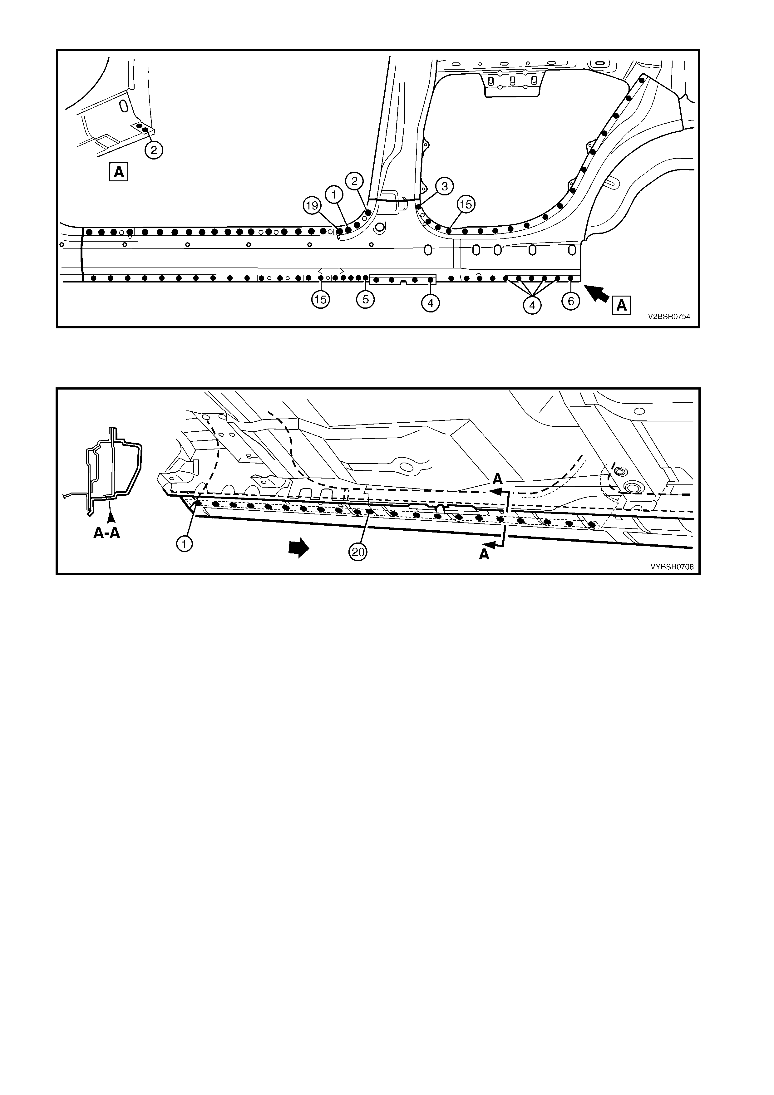
Figure 7D-97
20. Plug weld up through the rocker panel to attach the replacement section to the quarter panel inner assembly.
Refer to Figure 7D-98.
Figure 7D-98
21. Spot or plug weld two places, the door opening f rame as sem bly to the quarter panel inner assem bly ar ound
the rear wheel arch.
NOTE: This joint will be completed when the rear quarter panel is installed.
22. Clean up the welds made where the rear quarter panel is located and prime all bare metal.
23. Replace the rear quarter panel, refer to 2.1 REAR QUARTER PANEL – REPLACE.
24. Refinish and paint panels and other components as required. Refer to Section 3, 1.3 PAINT REFINISHING.
25. Apply Joint Sealer (Item 3) as required. Refer to 5. BODY SEALING, ADHESIVES & DEADENERS in
Section 3D.
26. Apply Cavity W ax (Item 8) as required to the ins ide of any box s ections or areas inacces sible to paint, refer
6. CAVITY WAX in Section 3D.
27. Install the rem aining com ponents as described in the appr opriate Section of the MY 2003 VY & V2 Series II
Service Information.
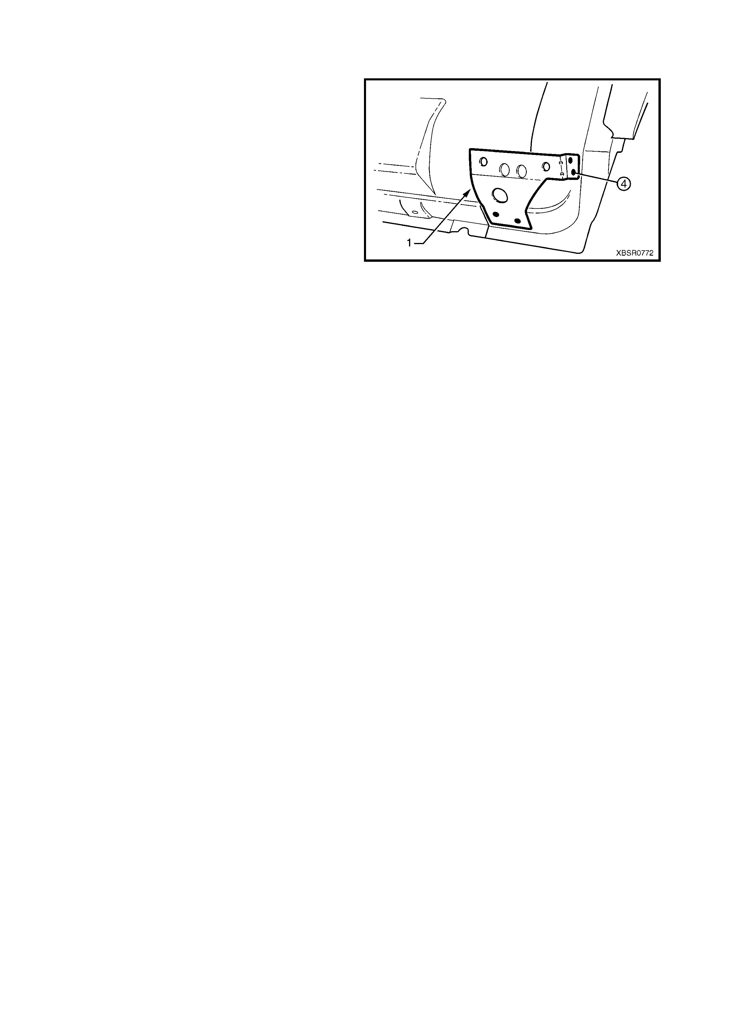
2.7 FENDER LOWER REAR BRACKET – REPLACE
The fender lower rear bracket (1) is spot welded at four
places to the door opening frame assembly.
Clamp the f ender lower rear brack et pos ition as shown
prior to plug welding and check the alignment of the
fender to the body and front door.
Refinish and paint panels and other components as
required. Refer to Section 3, 1.3 PAINT
REFINISHING.
Apply Cavity W ax (Item 8) as required to the inside of
any box sections or areas inaccessible to paint, refer
6. CAVITY WAX in Section 3D.
Figure 7D-99

2.8 HINGE PILLAR INNER PANEL ASSEMBLY – REPLACE
Replacement of the full hinge pillar inner panel
assembly requires removal of the door opening frame
assem bly and the roof panel. Alternatives are pr ovided
which avoid removal of the full door opening frame
assembly and roof panel. It is advisable to read the
options available in this procedure before removing
any panels.
REMOVE
1. Remove the adjacent bolt-on panels and
components as described in the appropriate
Section of the MY 2003 VY & V2 Series II Service
Information.
2. Remove the door opening frame assembly or the
hinge pillar section of the door opening frame
assembly as described earlier in this Section.
3. If required, rem ove the dash panel assem bly, ref er
to Section 5 COCKPIT MODULE in this
Supplement.
NOTE: If the das h panel assem bly is not dam aged, an
alternative is provided in this procedure which avoids
having to remove it.
4. Add bracing as required to maintain the alignment
of the vehicle structure.
Figure 7D-100
5. Grind the MIG welds (1) attaching the hinge pillar
inner panel assembly to the inner rocker panel.
Figure 7D-101
6. If full replacem ent is being perfor med, spot cut the
welds attaching the hinge pillar inner panel
assembly to the roof front header assembly and
quarter panel inner assembly.
NOTE 1: Some welds may have been removed with
the door opening frame assembly and roof panel.
NOTE 2: Structural adhesive is applied to join (1). If
the roof panel has not been removed, it will be very
difficult to remove the panel. As an alternative remove
hinge pillar section of the door opening frame
assembly then:
- If only the lower section is damaged, detach the
hinge pillar inner upper panel (1) from the hinge
pillar inner lower panel (2) and replace the lower
panel only, or
- Cut the hinge pillar inner panel assembly (3)
approximately 50 mm from the top of the
windscreen aperture. If a partial replacement of
the door opening frame assembly is being
performed, this point is 50 mm above the cut in
the outer panels (4). Refer to Figure 7D-103.
Figure 7D-102
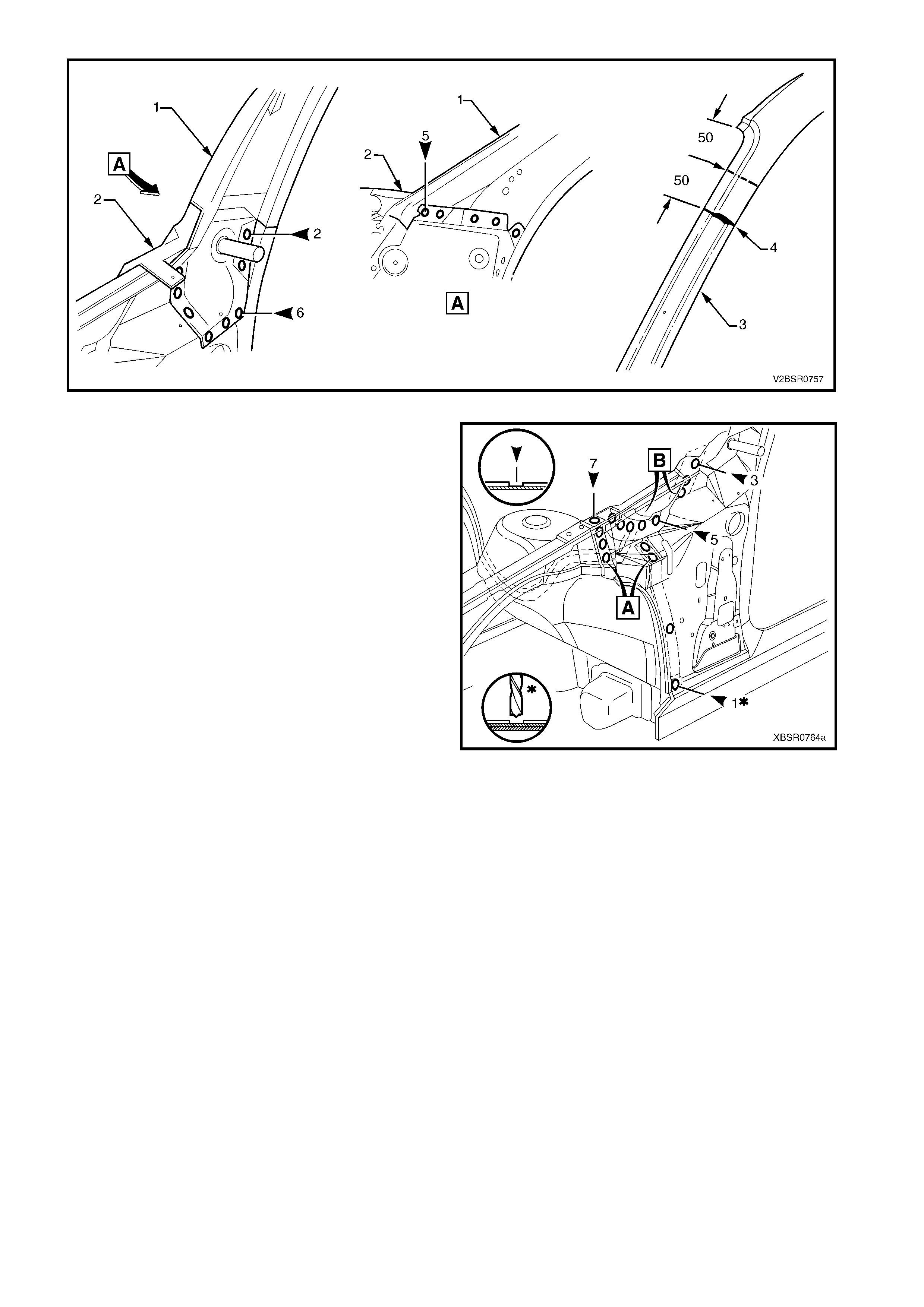
Figure 7D-103
7. Spot cut the welds attaching the hinge pillar inner
panel assembly (or lower panel) to the front
wheelhouse panel and front floor panel extension,
refer weld group A.
8. If the dash panel assem bly was not removed, spot
cut the eight welds attaching the adhesive
channels to the hinge pillar inner panel assembly,
refer weld group B.
9. If required, remove any remaining spot welds
where the front wheelhouse panel upper side rail
attached the front wheelhouse panel and hinge
pillar inner panel assembly.
10. Cut the adhesive between the dash panel
assembly and hinge pillar inner panel assembly.
11. Remo ve the hinge pillar inner panel as sembly from
the vehicle and as required, clean off any
remaining adhesive and ensure the adhesive
channels are removed.
12. Repair any damage to adjacent parts as required. Figure 7D-104
REPLACE
NOTE 1: Spot welding is the preferred method for attaching of panels and should be used whenever possible.
Where the spot welding equipment will not access the required weld position, a plug weld should be performed.
NOTE 2: The same number and position of s pot welds ( or plug welds) s hould be used when replacing the panel,
as was used during manufacture, in order to maintain the original structural strength of the vehicle.
1. If an alternate removal method was used, referring to Figure 7D-103 either:
- Cut the replacement section to match the cut at the top of the hinge pillar, or
- Spot cut the welds attaching the hinge pillar inner upper panel to the hinge pillar inner lower panel.
2. Mark the new panel and drill holes in preparation for plug welding where required.
3. Prepare all mating surfaces and treat with Weld Through Primer (Item 1) as required, refer to
5. BODY SEALING, ADHESIVES & DEADENERS in Section 3D.
4. If the dash panel assembly was removed, it will be installed later, proceed to step 7.
5. If the dash panel assembly was NOT removed, prepare the adhesive channels on the replacement section
and the dash panel assembly, refer to Section 5 COCKPIT MODULE.
6. Mix the dash panel silicone adhesive, refer to Section 5 COCKPIT MODULE. Apply the adhes ive to fill the
adhesive channels on the replacement section.
IMPORTANT: Only the correct material described in Section 5 COCKPIT MODULE is to be used.
7. If the f ull hinge pillar inner panel as s embly is being replaced, apply structural adhes ive (Item 6) to the mating
surfaces of the hinge pillar inner panel assembly and quarter panel inner assembly, refer to
5. BODY SEALING, ADHESIVES & DEADENERS in Section 3D.
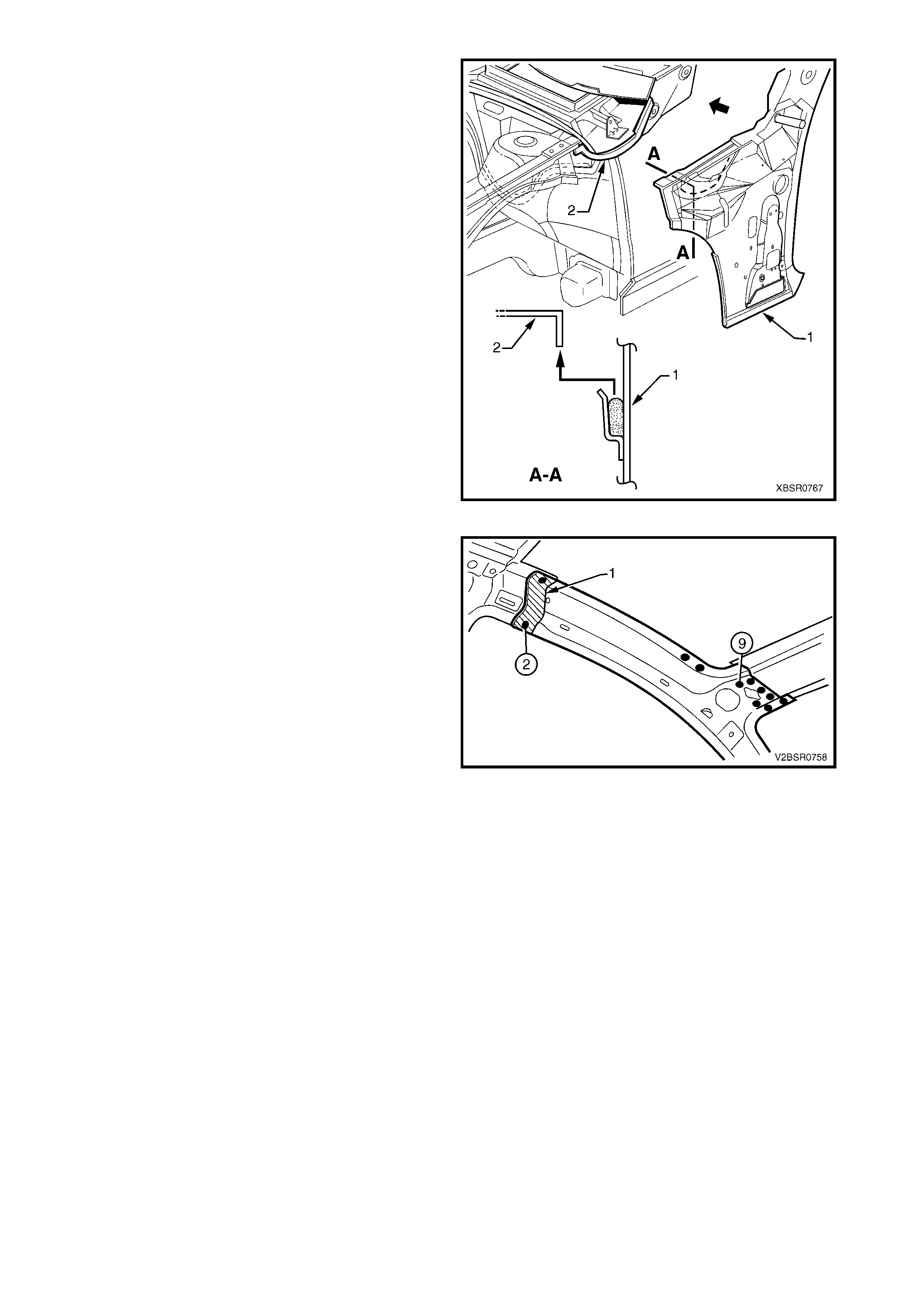
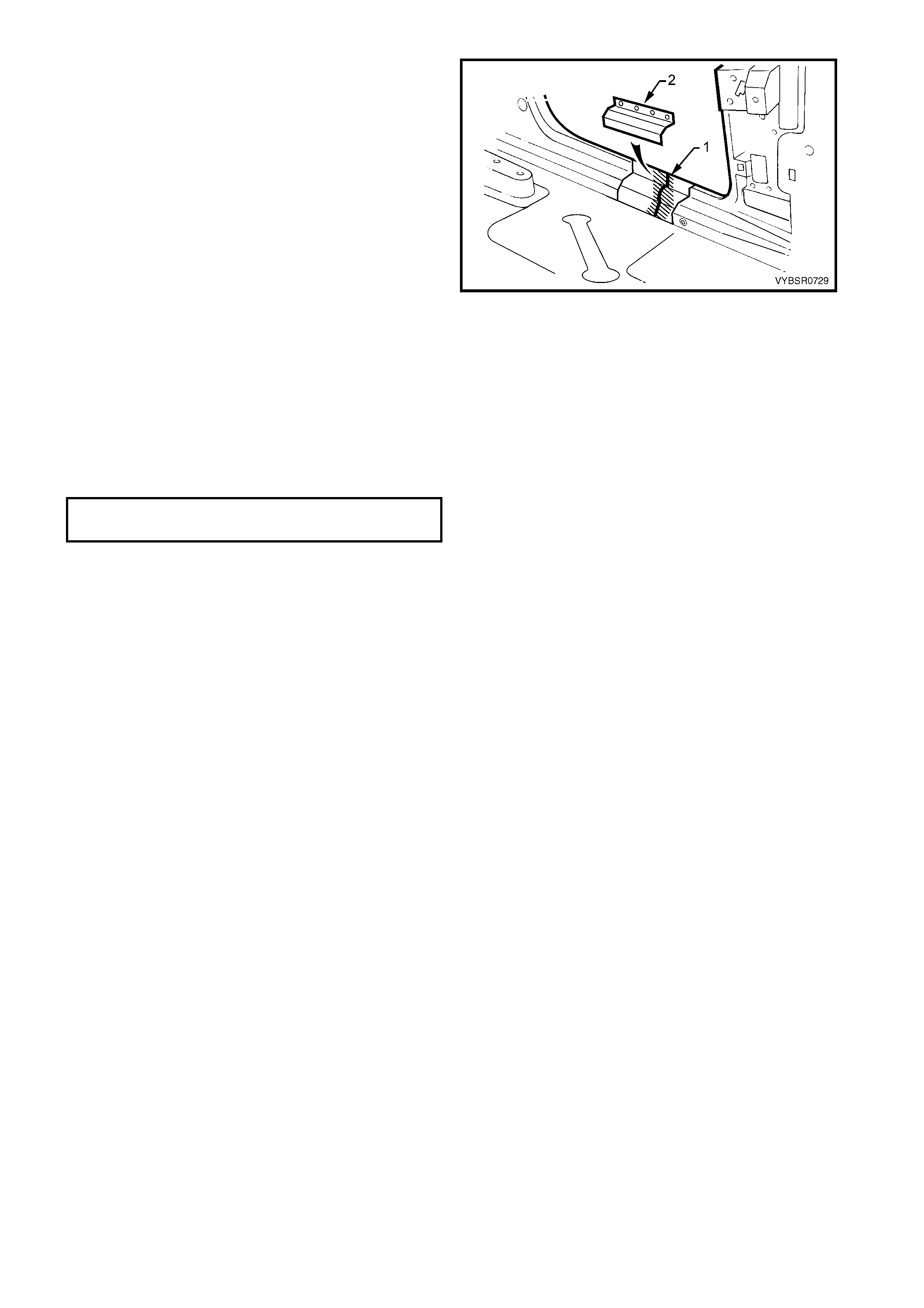
8. Install and clamp the panel in position on the
vehicle.
NOTE: If the dash panel assembly was not removed,
place the hinge pillar inner panel assembly (1) slightly
lower and slide it upwards ensuring the dash panel
flange (2) seats into the adhesive channel.
9. Temporarily install the dash panel assembly
attaching bolts through the hinge pillar inner panel
assembly and within the plenum chamber.
10. Finish the application of dash panel adhesive, refer
to Section 5 COCKPIT MODULE.
Figure 7D-105
11. If the full hinge pillar inner panel assembly was
removed, spot or plug weld the hinge pillar inner
panel assembly to the roof front header assembly
and quarter panel inner assembly.
NOTE: Ensure the structural adhesive (Item 6) is
applied to join (1), refer to 5. BODY SEALING,
ADHESIVES & DEADENERS in Section 3D.
12. If only the lower section was removed, spot or plug
weld the hinge pillar inner upper panel (1) to the
hinge pillar inner lower panel (2), refer to Figure
7D-107.
13. If the pillar was cut near the top of the windscreen
aperture, either MIG butt weld the join (3) if the full
door opening frame assembly was removed, or
make two tack welds to secure it until the door
opening frame assembly hinge pillar section is
installed, refer to Figure 7D-107.
NOTE: This join forms the top access cut point
for joining of the reinforcement as described in
2.4 DOOR OPENING FRAME ASSEMBLY –
PARTIAL REPLACE, HINGE PILLAR.
Figure 7D-106
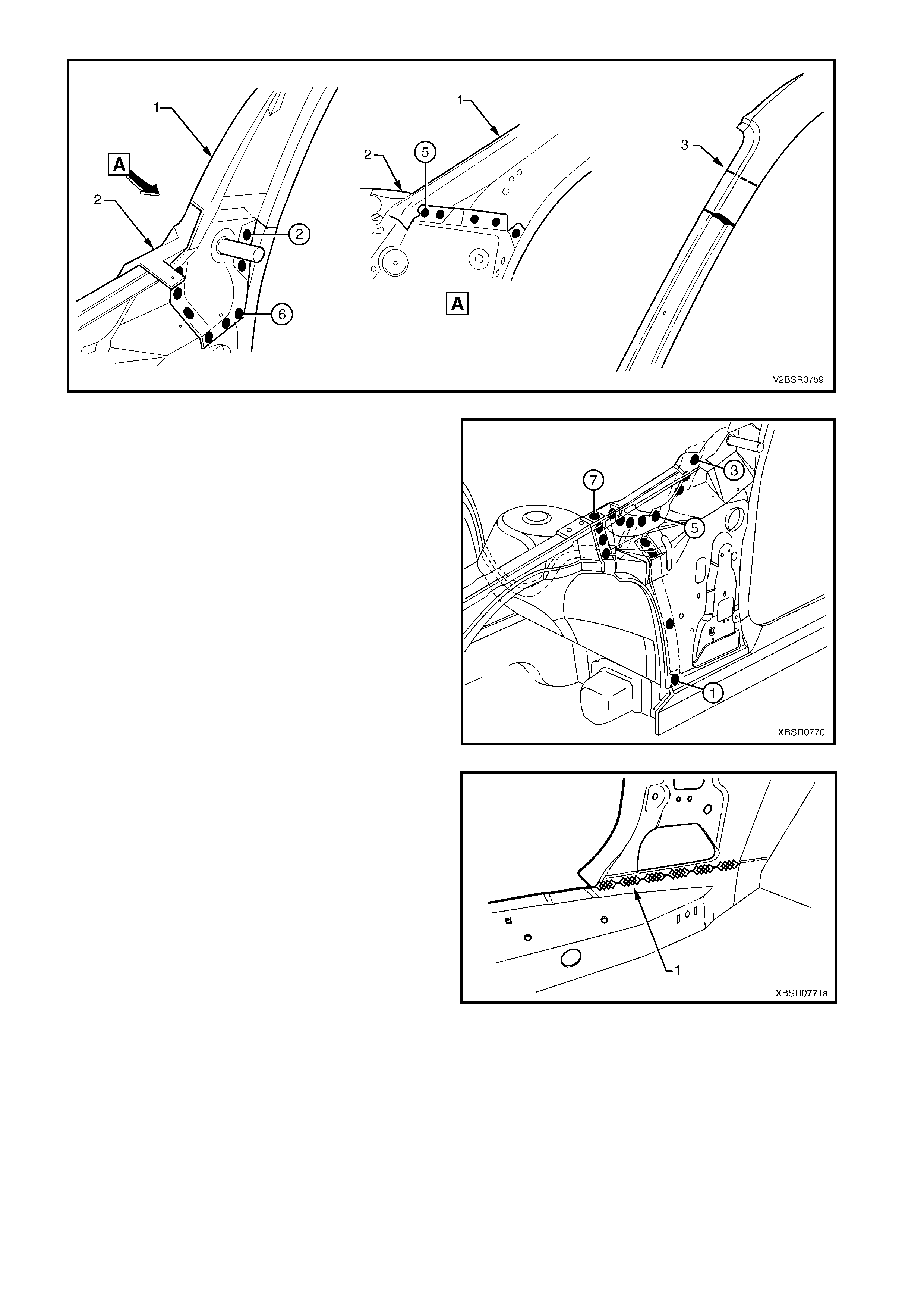
Figure 7D-107
14. Spot or plug weld the hinge pillar inner panel
assembly to the front wheelhouse panel and front
floor extension.
Figure 7D-108
15. MIG weld (1) across the inner rocker panel and
hinge pillar inner panel assembly.
16. Replace the door opening f rame assembly, refer to
2.3 DOOR OPENING FRAME ASSEMBLY –
REPLACE or the hinge pillar section of the
door opening frame assembly, refer to
2.4 DOOR OPENING FRAME ASSEMBLY –
PARTIAL REPLACE, HINGE PILLAR.
17. Refinish and paint panels and other components
as required. Refer to Section 3, 1.3 PAINT
REFINISHING.
18. Apply Joint Sealer (Item 3) as required. Refer to
5. BODY SEALING, ADHESIVES & DEADENERS
in Section 3D.
19. Apply Cavity Wax (Item 8) as r equired to the inside
of any box sections or areas inaccessible to paint,
refer 6. CAVITY WAX in Section 3D.
20. If required replace the dash panel assembly,
refer Section 5 COCKPIT MODULE in this
Supplement.
21. Install the remaining components as described in
the appropriate Section of the MY 2003 VY & V2
Series II Service Information.
Figure 7D-109
2.9 QUARTER PANEL INNER ASSEMBLY – REPLACE
REMOVE
1. Remove the adjacent bolt-on panels and
components as described in the appropriate
Section of the MY 2003 VY & V2 Series II Service
Information.
2. Mount the vehicle on a suitable jig to maintain
correct body alignment when the quarter panel
inner assembly is removed.
3. Rem ove the rear quarter panel, refer to 2.1 REAR
QUARTER PANEL – REPLACE.
4. Remove the roof panel, and partially remove the
roof bow panel and roof rear panel, refer to
Section 9 ROOF.
5. Remove the door opening frame assembly, refer
to 2.3 DOOR OPENING FRAME ASSEMBLY –
REPLACE.
6. Add further bracing tools as required, to maintain
the alignment of the vehicle structure.
Figure 7D-110
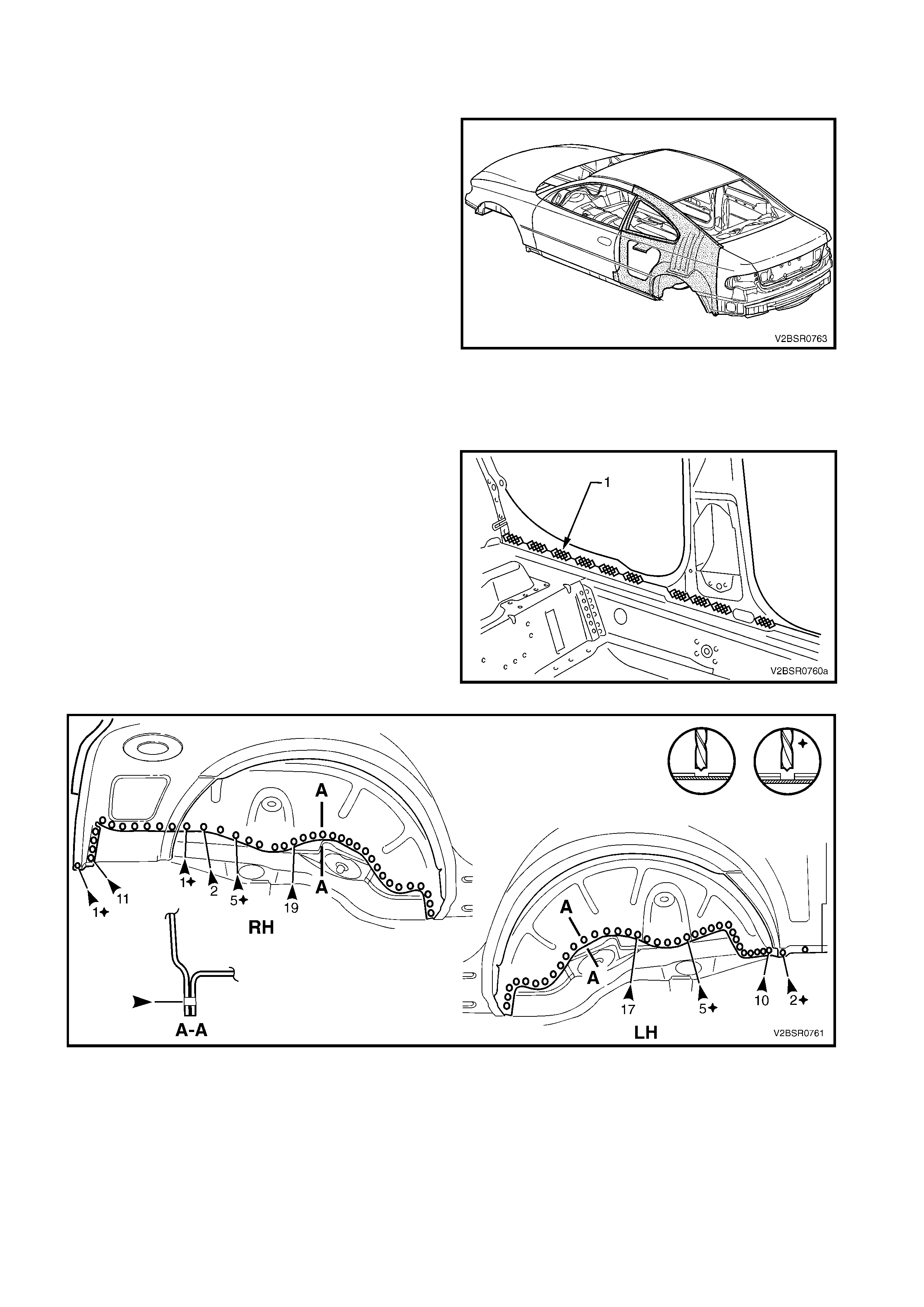
7. Grind the MIG welds (1), 11 places, attaching the
quarter panel inner assembly to the inner rocker
panel.
8. Spot cut the welds attaching the rear wheelhouse
inner (1) to the rear floor panel assembly, refer to
Figure 7D-112.
Figure 7D-111
Figure 7D-112
9. Spot cut the welds attaching the rear window panel assembly to the rear seat back extension assembly,
refer to Figure 7D-113.
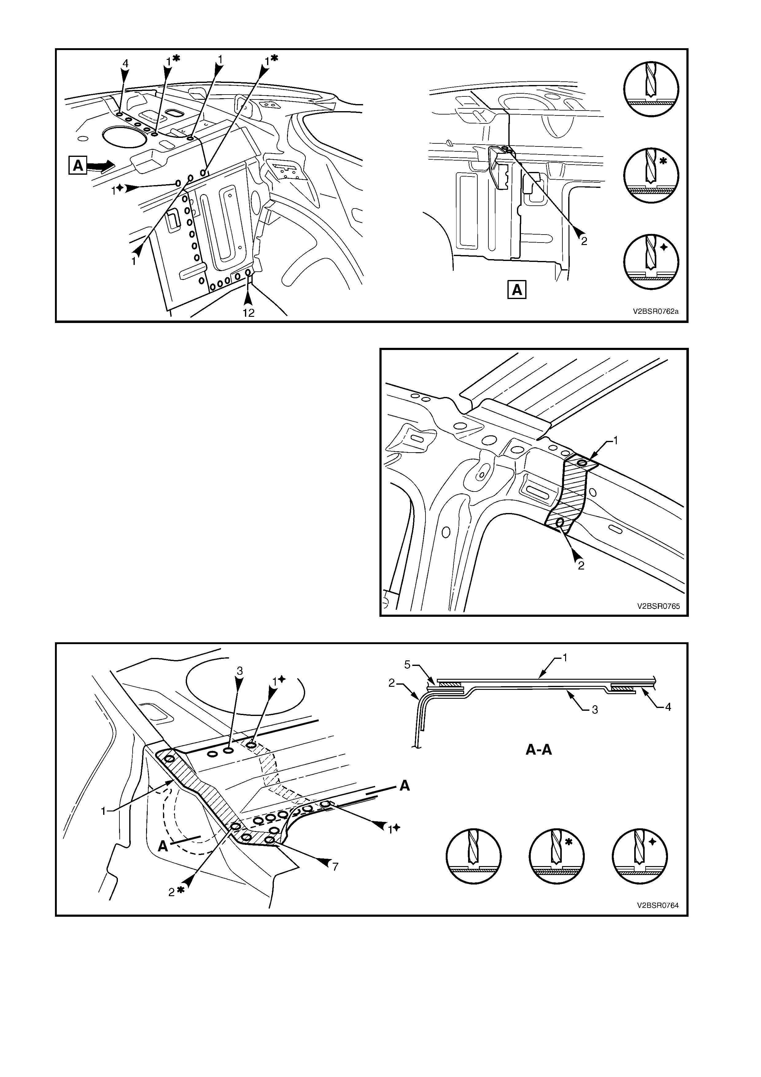
Figure 7D-113
10. The hinge pillar inner panel assembly is attached
to the quarter panel inner assembly with spot
welds and structural adhesive (1) (Item 6, refer to
5. BODY SEALING, ADHESIVES & DEAD ENERS
in Section 3D). As the adhesive is extremely
strong, cut through the quarter panel inner
assembly just behind the join and remove the
remaining joint piece with a grinder.
11. As required, spot cut the welds attaching the rear
window panel assembly (1 & 4) to the quarter
panel inner (2) and rear seat back extension
assembly (3).
NOTE 1: Structural adhesive (Item 6) is applied in the
areas shown shaded. As this material is extremely
strong, the rear seat back extension assembly may
require removing with a grinder.
NOTE 2: Remove the remaining flange of the rear
quarter panel (5), leaving only the rear window panel
assembly.
Figure 7D-114
Figure 7D-115
12. Remove the quarter panel inner assembly from the vehicle, then repair any damage to adjacent parts as
required.
13. Check and rectify the alignment of the body as required, refer to 3. BODY DIMENSIONS in Section 3D.
REPLACE
NOTE 1: Spot welding is the preferred method for attaching of panels and should be used whenever possible.
Where the spot welding equipment will not access the required weld position, a plug weld should be performed.
NOTE 2: The same number and position of s pot welds ( or plug welds) s hould be used when replacing the panel,
as was used during manufacture, in order to maintain the original structural strength of the vehicle.
1. Mark the new panel and drill holes in preparation for plug welding where required.
2. Prepare all mating surfaces and treat with Weld Through Primer (Item 1) as required, refer to
5. BODY SEALING, ADHESIVES & DEADENERS in Section 3D.
3. Apply Structural Adhesive (Item 6, re f er to 5. BO DY SEALING, ADHESIVES & DEADENERS in Sect ion 3D)
to the mating surfaces of the:
- Hinge pillar inner panel assembly, refer to Figure 7D-116, and
- Inner joint ONLY of the rear seatback extension (part of the quarter panel inner assembly), refer to Figure
7D-117.
NOTE: Adhesive will be applied to the outer rear window panel assembly joint when the rear quarter panel is
installed.
4. Clamp the new panel in position on the vehicle.
5. Plug or s pot weld the quarter panel inner as sembly
to the hinge pillar inner assembly join.
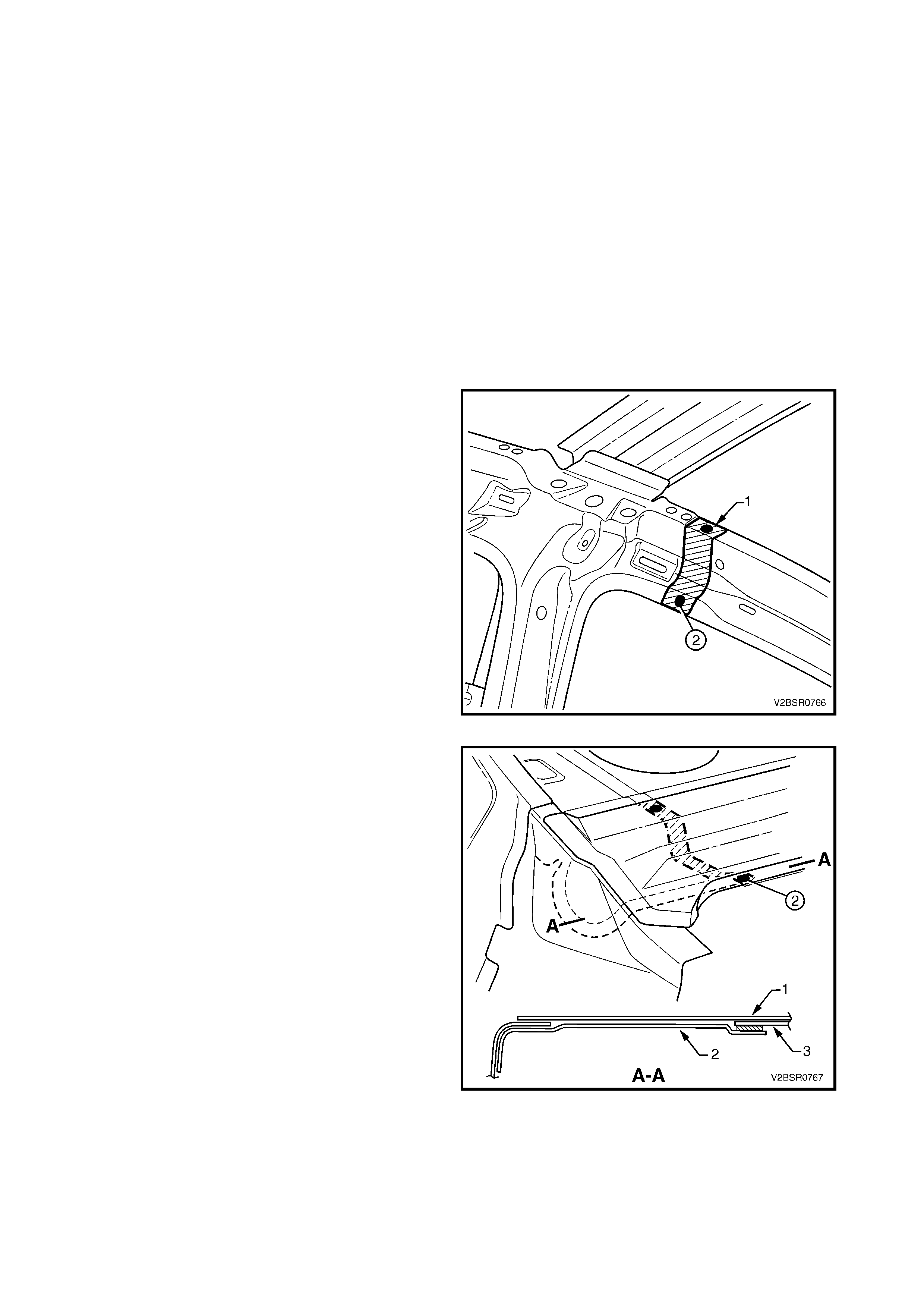
Figure 7D-116
6. Spot or plug weld two places, the rear window
panel assembly (1 & 3) to the, rear seat back
extension (2).
NOTE: T his ar ea will be completed as the rear quarter
panel is installed.
7. Spot or plug weld the r ear window panel assem bly
to the rear seat back extension assembly, refer to
Figure 7D-118.
Figure 7D-117

Figure 7D-118
8. Spot or plug weld the rear wheelhouse inner (1) to the rear floor panel assembly, refer to Figure 7D-119.
Figure 7D-119
9. MIG weld 11 places (1), the quarter panel inner
assembly to the inner rocker panel.
10. Clean up welds as required and prime any bare
metal.
11. Install the door opening frame assembly, refer to
2.3 DOOR OPENING FRAME ASSEMBLY –
REPLACE.
12. Replace the roof and roof bow panel and roof rear
panel, refer to Section 9 ROOF.
13. Prepare the rear quarter panel f or installation, ref er
to 2.1 REAR QUARTER PANEL – REPLACE.
IMPORTANT: Do NOT modify the rear quarter panel
flange at the base of the rear window as stated in the
rear quarter panel replacement procedure, as the
flange is required for this procedure.
Figure 7D-120

14. Apply structural adhesive (Item 6, refer to
5. BODY SEALING, ADHESIVES & DEAD ENERS
in Section 3D) to the rear quarter panel flange as
shown.
15. Fit and clamp the rear quarter panel into position,
refer to 2.1 REAR QUARTER PANEL –
REPLACE.
IMPORTANT: Ensure the rear quarter flange (1) is
fitted between the quarter panel inner assembly (2)
and rear window panel assembly (3). If required prise
up the rear window panel assembly to provide
clearance, also refer to Figure 7D-122.
Figure 7D-121
16. Spot or plug weld through the rear window panel
assembly as shown.
17. Complete the rear quarter panel, refer to
2.1 REAR QUARTER PANEL – REPLACE.
18. Refinish and paint panels and other components
as required. Refer to Section 3, 1.3 PAINT
REFINISHING.
19. Apply Joint Sealer (Item 3) as required. Refer to
5. BODY SEALING, ADHESIVES & DEADENERS
in Section 3D.
20. Apply Cavity Wax (Item 8) as r equired to the inside
of any box sections or areas inaccessible to paint,
refer to 6. CAVITY WAX in Section 3D.
21. Install the remaining components as described in
the appropriate Section of the MY 2003 VY & V2
Series II Service Information.
Figure 7D-122
2.10 QUARTER PANEL INNER ASSEMBLY – PARTIAL REPLACE
REMOVE
1. Remove the adjacent bolt-on panels and
components as described in the appropriate
Section of the MY 2003 VY & V2 Series II Service
Information.
2. Mount the vehicle on a suitable jig to maintain
correct body alignment when the quarter panel
inner assembly is removed.
3. Rem ove the rear quarter panel, refer to 2.1 REAR
QUARTER PANEL – REPLACE.
4. Remove the rear section of the door opening
frame assembly, refer to 2.3 DOOR OPENING
FRAME ASSEMBLY – PARTIAL REPLACE,
ROCKER PANEL.
Figure 7D-123
5. Carefully cut through the quarter panel inner
assembly at the rocker panel region.
NOTE: The position of the cut (1) should be a
minimum of 50 mm shorter than that of the door
opening frame (2) to allow sufficient access for
rejoining.
Figure 7D-124
6. Depending on the cut location, grind the MIG
welds (1), attaching the quarter panel inner
assembly to the inner rocker panel.
7. Spot cut the welds attaching the rear wheelhouse
inner (1) to the rear floor panel assembly, refer to
Figure 7D-126.
Figure 7D-125
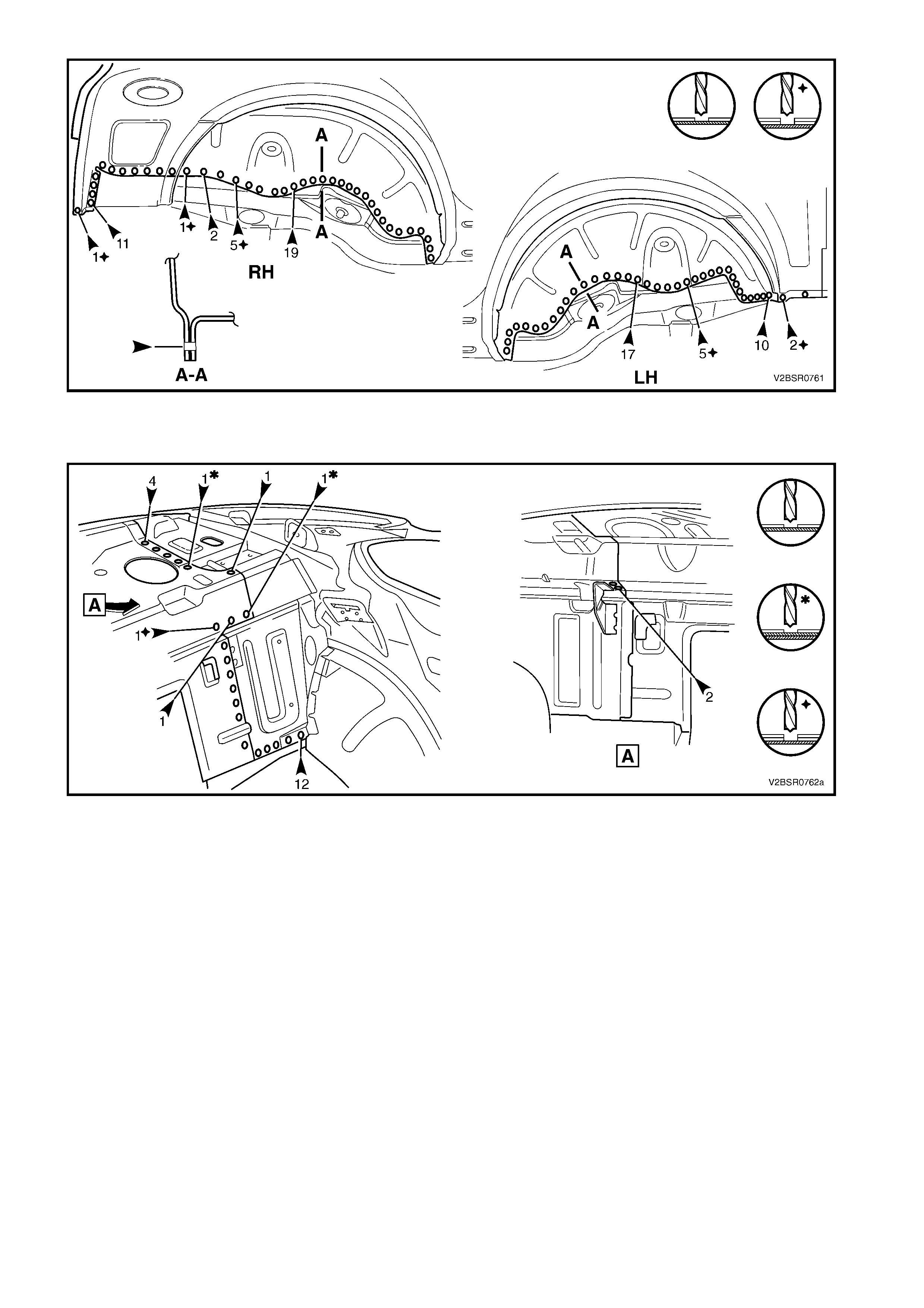
Figure 7D-126
8. Spot cut the welds attaching the rear window panel assembly to the rear seat back extension assembly,
refer to Figure 7D-127.
Figure 7D-127
9. As required, spot cut the welds attaching the r ear window panel ass embly (1 & 4) to the quarter panel inner
(2) and rear seat back extension assembly (3).
NOTE 1: Str uctur al adhes ive ( Item 6) is applied in the areas s hown shaded. As this material is ex tremely strong,
the rear seat back extension assembly may require removing with a grinder.
NOTE 2: Remove the remaining flange of the rear quarter panel (5), leaving only the rear window panel
assembly.
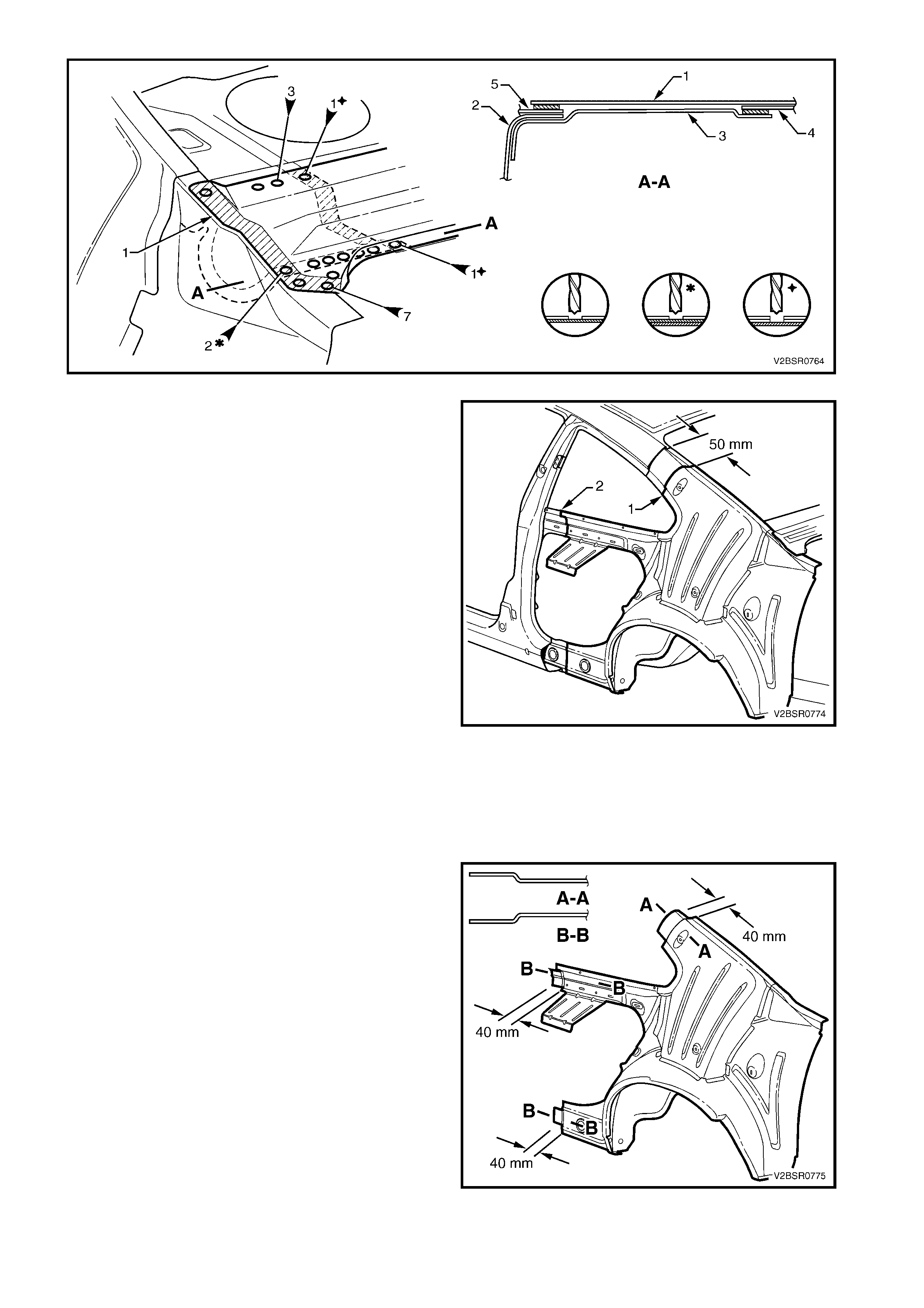
Figure 7D-128
10. Cut the quarter panel inner assembly through the
lock (1) at a point 50 mm below the end of the door
opening frame.
11. Cut through the quarter panel inner assembly at a
point rearward of the centre pillar (2).
12. Remove the partial quarter panel inner assembly
from the vehicle, then repair any damage to
adjacent parts as required.
13. Check and rectify the alignment of the body as
required, refer to 3. BODY DIMENSIONS in
Section 3D.
Figure 7D-129
REPLACE
NOTE 1: Spot welding is the preferred method for attaching of panels and should be used whenever possible.
Where the spot welding equipment will not access the required weld position, a plug weld should be performed.
NOTE 2: The same number and position of s pot welds ( or plug welds) s hould be used when replacing the panel,
as was used during manufacture, in order to maintain the original structural strength of the vehicle.
1. Accurately cut the replacem ent s ection f rom a new
quarter panel inner assembly. The new section
should be cut 40 mm longer at the mating f aces to
allow for overlap.
NOTE: Cut the quarter panel inner at the upper lock
pillar join correct length to facilitate a butt joint.
2. Rem ove the flanges from the overlapping sections
and form a joggle to facilitate a lap joint. Make the
lock pillar reinforcement joggle inward and the
other joggles outward.
3. Mark the new panel and the existing panels with
drilling locations in preparation for plug welding
where required. Drill holes as marked.
4. Prepare all mating surfaces and treat with Weld
Through Primer (Item 1) as required, refer to
5. BODY SEALING, ADHESIVES & DEADENERS
in Section 3D.
Figure 7D-130
5. Apply Structural Adhesive (Item 6, refer to
5. BODY SEALING, ADHESIVES & DEADENERS
in Section 3D) to the inner joint ONLY of the rear
seatback extension (par t of the quarter panel inner
assembly).
NOTE: Adhesive will be applied to the outer rear
window panel assembly joint when the rear quarter
panel is installed.
6. Position the new panel on the vehicle and clamp in
place.
7. Spot or plug weld two places, the rear window
panel assembly (1 & 3) to the, rear seat back
extension (2).
NOTE: T his ar ea will be completed as the rear quarter
panel is installed.
Figure 7D-131
8. Plug weld the lap joints.
9. Finish the joints by MIG welding along the join.
10. From inside the vehicle, MIG weld the quarter
panel inner at the upper lock pillar join.
11. Spot or plug weld the rear window panel assembly
to the rear seat back extension assembly, refer to
Figure 7D-133.
Figure 7D-132
Figure 7D-133
12. Spot or plug weld the wheelhouse inner (1) to the rear floor panel assembly, refer to Figure 7D-134.
Figure 7D-134
13. As required, MIG weld (1), the quarter panel inner
assembly to the inner rocker panel.
14. Clean up the welds as required and prime any
bare metal.
15. Install the rear section of the door opening frame
assembly, refer to 2.3 DOOR OPENING FRAME
ASSEMBLY – PARTIAL REPLACE, ROCKER
PANEL.
16. Prepare the rear quarter panel f or installation, ref er
to 2.1 REAR QUARTER PANEL – REPLACE.
IMPORTANT: Do NOT modify the rear quarter panel
flange at the base of the rear window as stated in the
rear quarter panel replacement procedure, as the
flange is required for this procedure.
Figure 7D-135
17. Apply structural adhesive (Item 6, refer to
5. BODY SEALING, ADHESIVES & DEAD ENERS
in Section 3D) to the rear quarter panel flange as
shown.
18. Fit and clamp the rear quarter panel into position,
refer to 2.1 REAR QUARTER PANEL –
REPLACE.
IMPORTANT: Ensure the rear quarter flange (1) is
fitted between the quarter panel inner assembly (2)
and rear window panel assembly (3). If required prise
up the rear window panel assembly to provide
clearance, also refer to Figure 7D-137.
Figure 7D-136
19. Spot or plug weld through the rear window panel
assembly as shown.
20. Complete the rear quarter panel, refer to
2.1 REAR QUARTER PANEL – REPLACE.
21. Refinish and paint panels and other components
as required. Refer to Section 3, 1.3 PAINT
REFINISHING.
22. Apply Joint Sealer (Item 3) as required. Refer to
5. BODY SEALING, ADHESIVES & DEADENERS
in Section 3D.
23. Apply Cavity Wax (Item 8) as r equired to the inside
of any box sections or areas inaccessible to paint,
refer to 6. CAVITY WAX in Section 3D.
24. Install the remaining components as described in
the appropriate Section of the MY 2003 VY & V2
Series II Service Information.
Figure 7D-137