
SECTION 9 - ROOF
IMPORTANT
Before perfo rming any Service O perat ion or o th er pro cedu re describ ed in th is Section, refer to Section
00 CAUTIONS AND NOTES and Section 2 PRECAUTIONS in this Supplement for correct workshop
practices with regard to safety and/or property damage.
CAUTION
The Structure of the M Y 2003 VY & V2 Series II body shell has been developed using complex design
and development techniques. In addition to meeting all required standards, the v ehicle body is also a
critical part of the overall safety systems. It is therefore imperative the repair procedures described
here are adhered to during all vehicle body repairs.
1. GENERAL DESCRIPTION
1.1 ROOF COMPONENTS
2. SERVICE OPERATIONS
2.1 ROOF PANEL, SEDAN,
WITHOUT SUNROOF – REPLACE
REMOVE
REPLACE
2.2 ROOF PANEL, SEDAN, WITH SUNROOF –
REPLACE
REMOVE
REPLACE
2.3 ROOF PANEL, WAGON – REPLACE
REMOVE
REPLACE
2.4 ROOF PANEL, UTILITY – REPLACE
REMOVE
REPLACE
2.5 ROOF PANEL, COUPE – REPLACE
REMOVE
REPLACE
2.6 ROOF FRONT HEADER PANEL – REPLACE
2.7 ROOF BOW PANELS – REPLACE
SEDAN & COUPE
WAGON, ROOF BOW PANEL NO. 1
WAGON, ROOF BOW PANEL NO. 3
WAGON, ROOF BOW PANEL NO. 2 & 4
2.8 ROOF REAR PANEL – REPLACE
SEDAN & COUPE
WAGON
UTILITY
1. GENERAL DESCRI PTI O N
This Section describes the replacement procedures for the roof structure of MY 2003 VY & V2 Series II vehicles.
The components covered include the roof panel and the roof header, bow and rear panels.
Removal of trim and bolt-on components is not covered. Reference must be made to the appropriate Sections in
the MY 2003 VY & V2 Series II Service Information.
The roof panel is both spot welded and glued in place with structural adhesive. Heating or other normal means
cannot soften this adhesive and the panel can only be removed by cutting and/or grinding.
A sunroof option is available on Sedan vehicles that is fitted on the production line. To cater for this option, a new
roof structure has been introduced which features a housing assembly in place of the roof bow panel. The roof
panel f or vehicles with the sunroof is serviced as an as sembly with the s unroof housing attached. A s tainless steel
front drain tube is also fitted within the hinge pillar cavity which affects the service procedures for the hinge pillar,
refer to Section 7A BODY SIDE – SEDAN.
When repairing the roof structure, care must be taken to ensure it is returned to its original production configuration.
NOTE: It is imperative that the correct body adhesives, sealers, deadeners and cavity waxes are used when
repairing the body structure of MY 2003 VY & V2 Series II vehicles. Refer to 5. BODY SEALING, ADHESIVES &
DEADENERS and 6. CAVITY WAX in Section 3A (Sedan), Section 3B (Wagon), Section 3C (Utility) or
Section 3D (Coupe) for details of the correct materials and their commercially available equivalents.
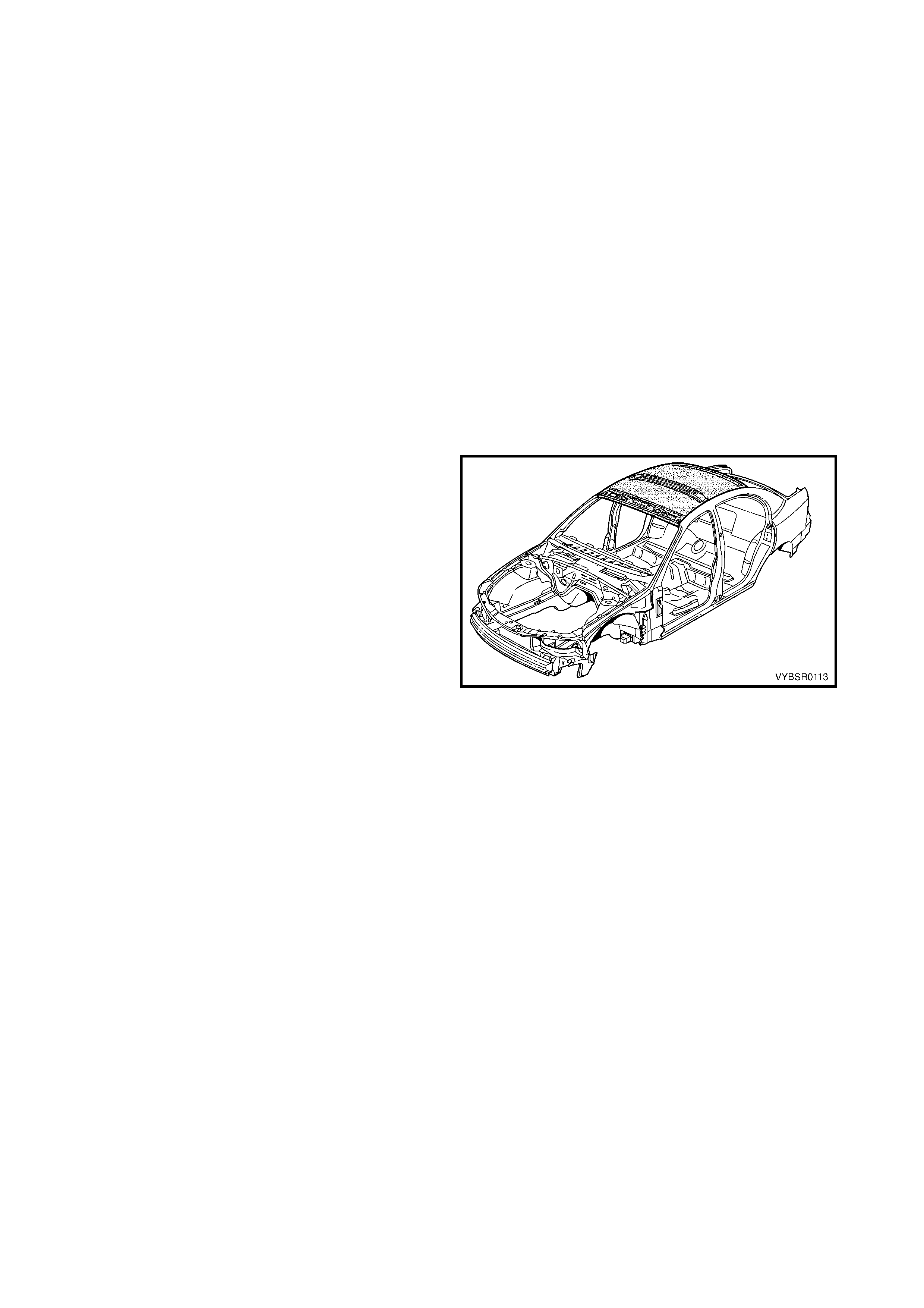
1.1 ROOF COMPONENTS
The shaded components in Figure 9-1 are those dealt
with in this Section.
The components and assemblies shown in Figure 9-2
are the parts serviced for MY 2003 VY & V2 Series II
vehicles which form the basis of the repair procedures
in this Section. For a detailed view of the body
components, refer to:
Section 3A BODY CONSTRUCTION – SEDAN,
Section 3B BODY CONSTRUCTION – WAGON,
Section 3C BODY CONSTRUCTION – UTILITY or
Section 3D BODY CONSTRUCTION – COUPE.
NOTE: Always refer to your Authorised Retailer for
spare parts availability configurations. Figure 9-1
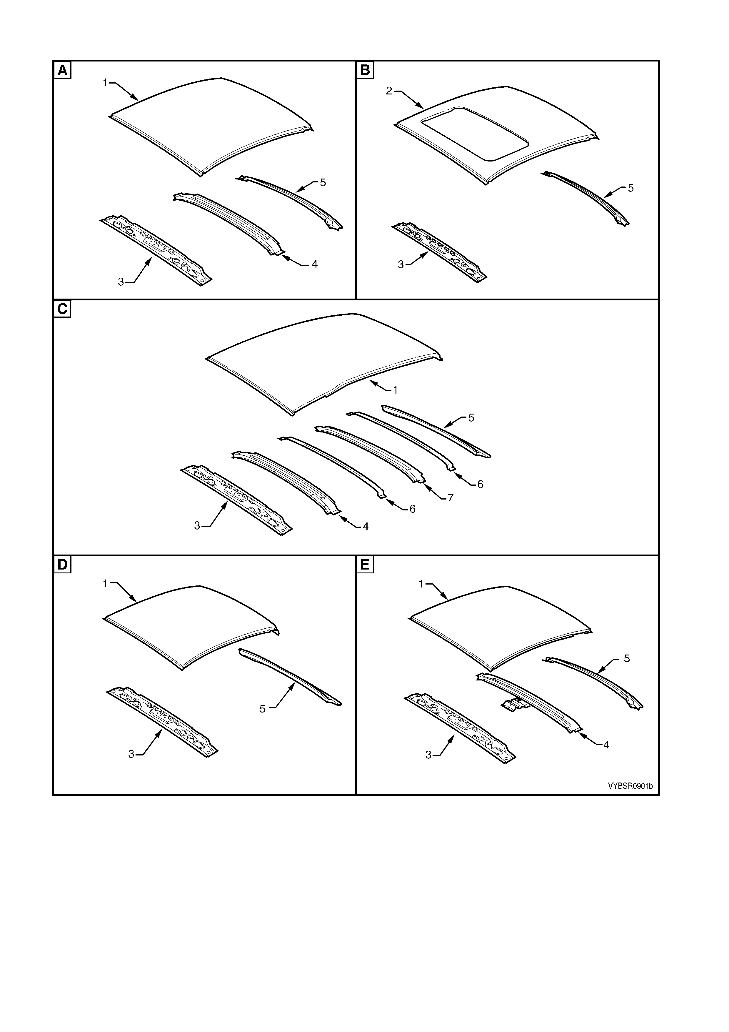
Figure 9-2
Legend
A. Sedan without sunroof
B. Sedan with sunroof
C. Wagon
D. Utility
E. Coupe
1. Roof Panel
2. Roof Panel Assembly
3. Roof Front Header Panel
4. Roof Bow Panel
5. Roof Rear Panel
6. Roof Bow Panel No. 2
7. Roof Bow Panel No. 3
2. SERVICE OPERATIONS
2.1 ROOF PANEL, SEDAN, WITHOUT SUNROOF – REPLACE
REMOVE
1. Remove the adjac ent trim and c omponents as des cr ibed in the appropr iate Sec tion of the MY 2003 VY & V2
Series II Service Information.
2. Remove the windshield and rear window, refer to Section 1A6, STATIONARY WINDOWS in the MY 2003
VY & V2 Series II Service Information.
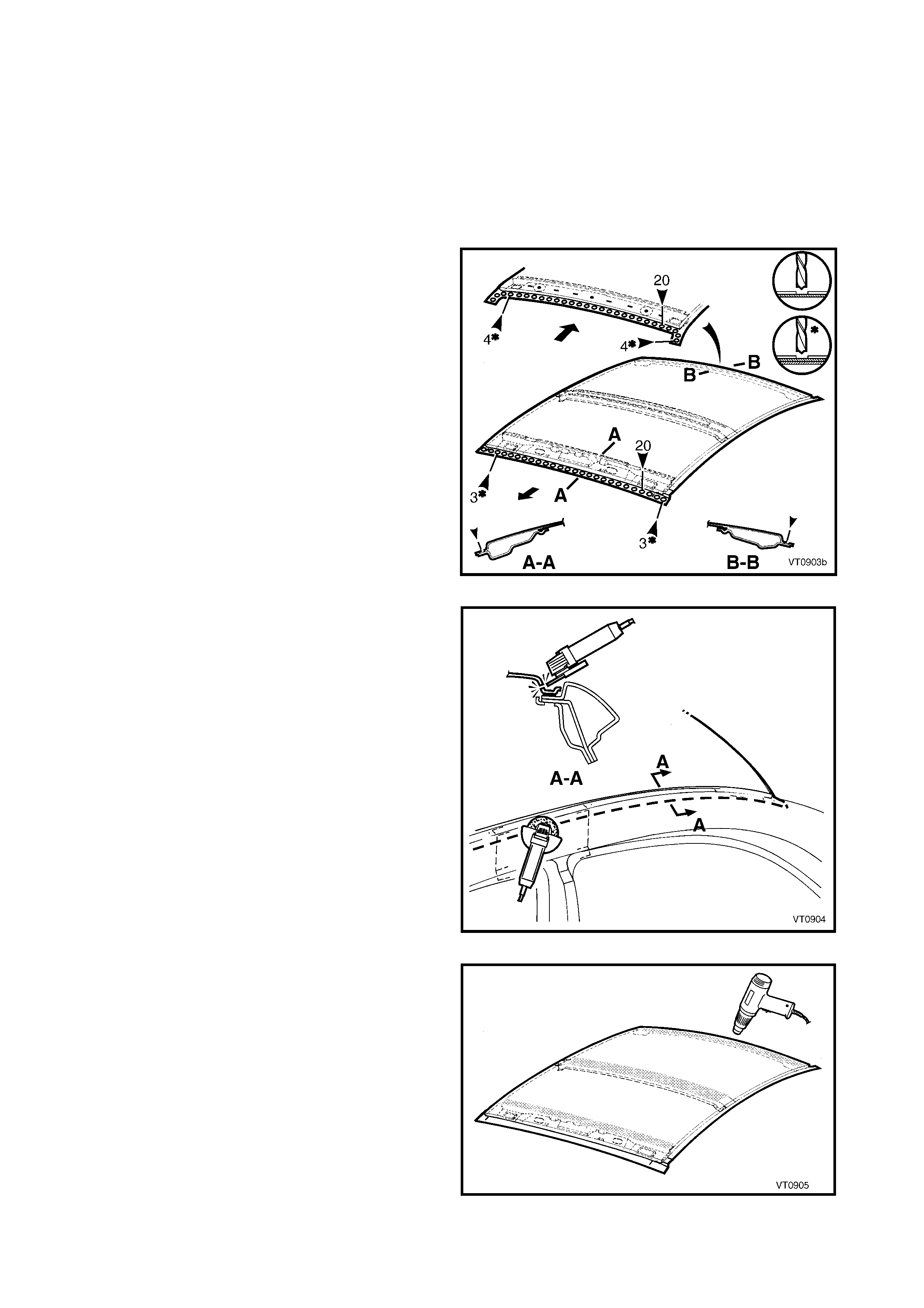
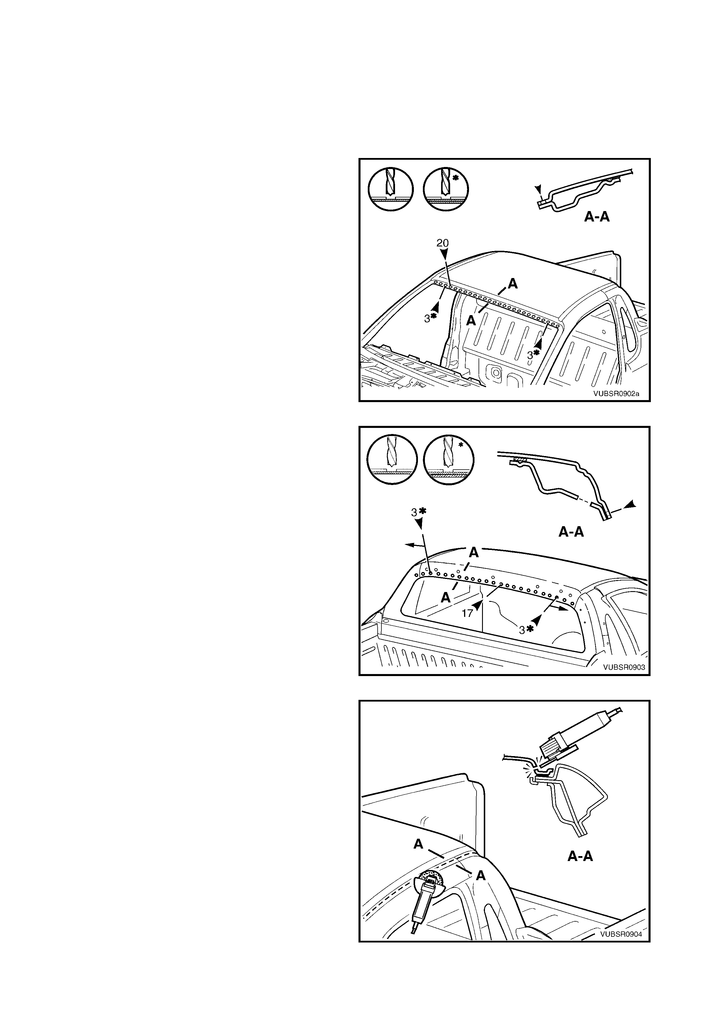
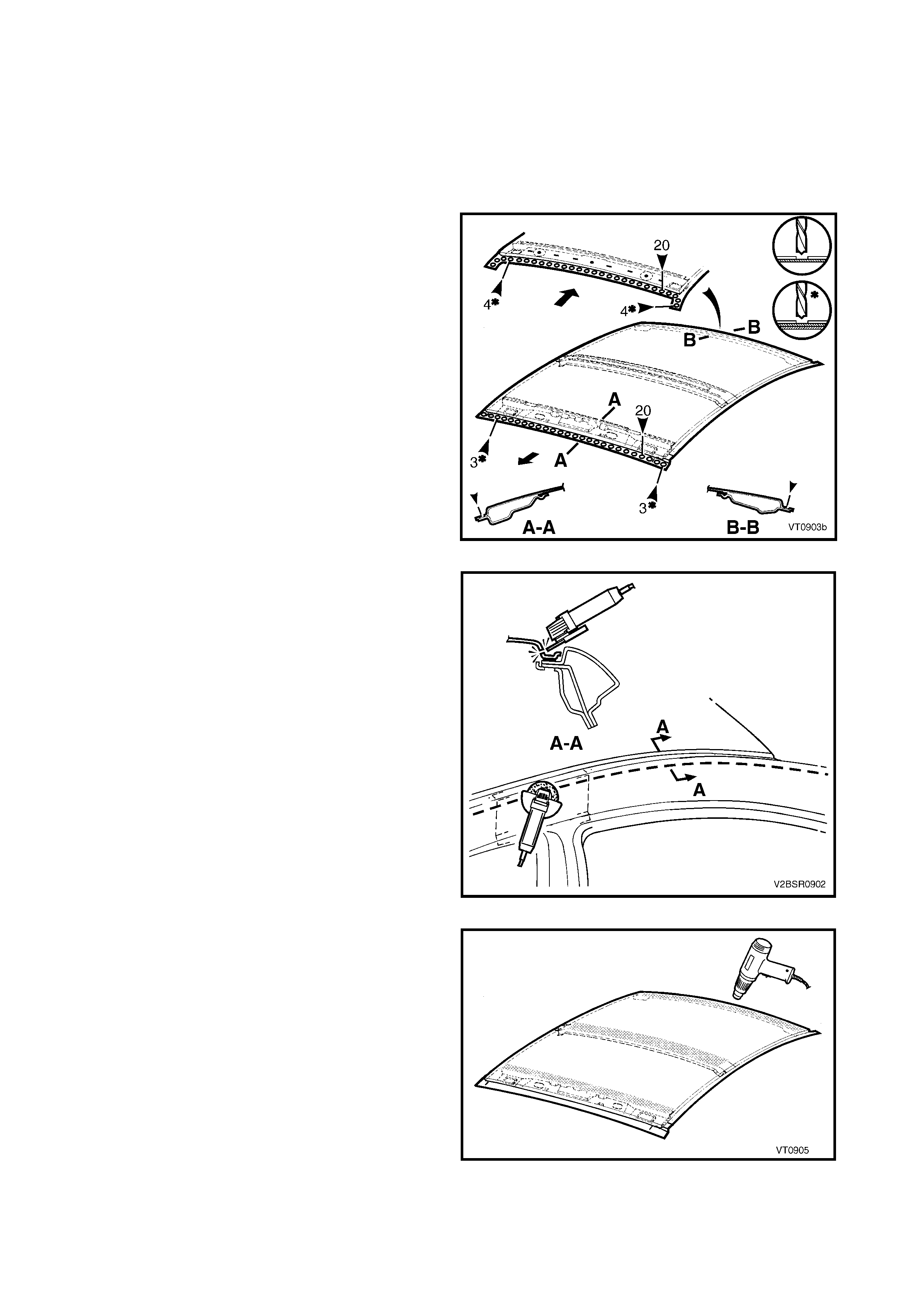
3. Spot cut the welds attaching the roof panel to the
roof front header panel and roof rear panel.
Figure 9-3
4. Using a cutting tool such as an air chisel or angle
grinder, cut through the roof panel along the side
of the roof channel.
NOTE 1: As the roof panel is securely glued to the
body side panel along the channel, it cannot be
removed by simply spot cutting the welds.
NOTE 2: If the roof front header panel, roof bow panel
and roof r ear panel are to be retained, tak e care not to
cut them off with the roof panel. Alternatively, if one or
more are to be replaced, it is easier to cut off those
being replaced along with the roof panel.
Figure 9-4
5. Use a heat gun to soften the Anti-flutter adhesive
between the roof front header panel, roof bow
panel and roof rear panel by heating the areas
shown.
Figure 9-5
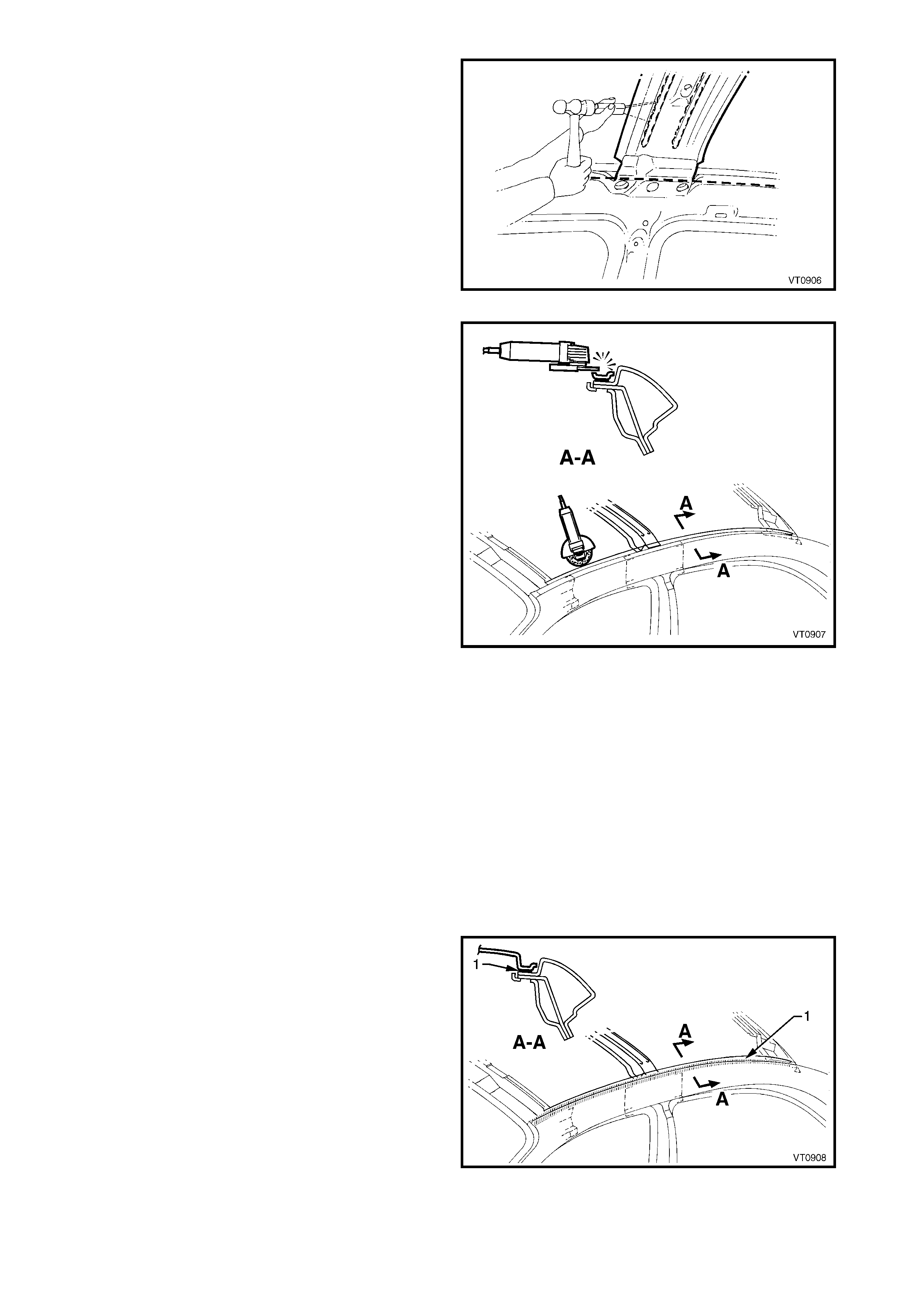
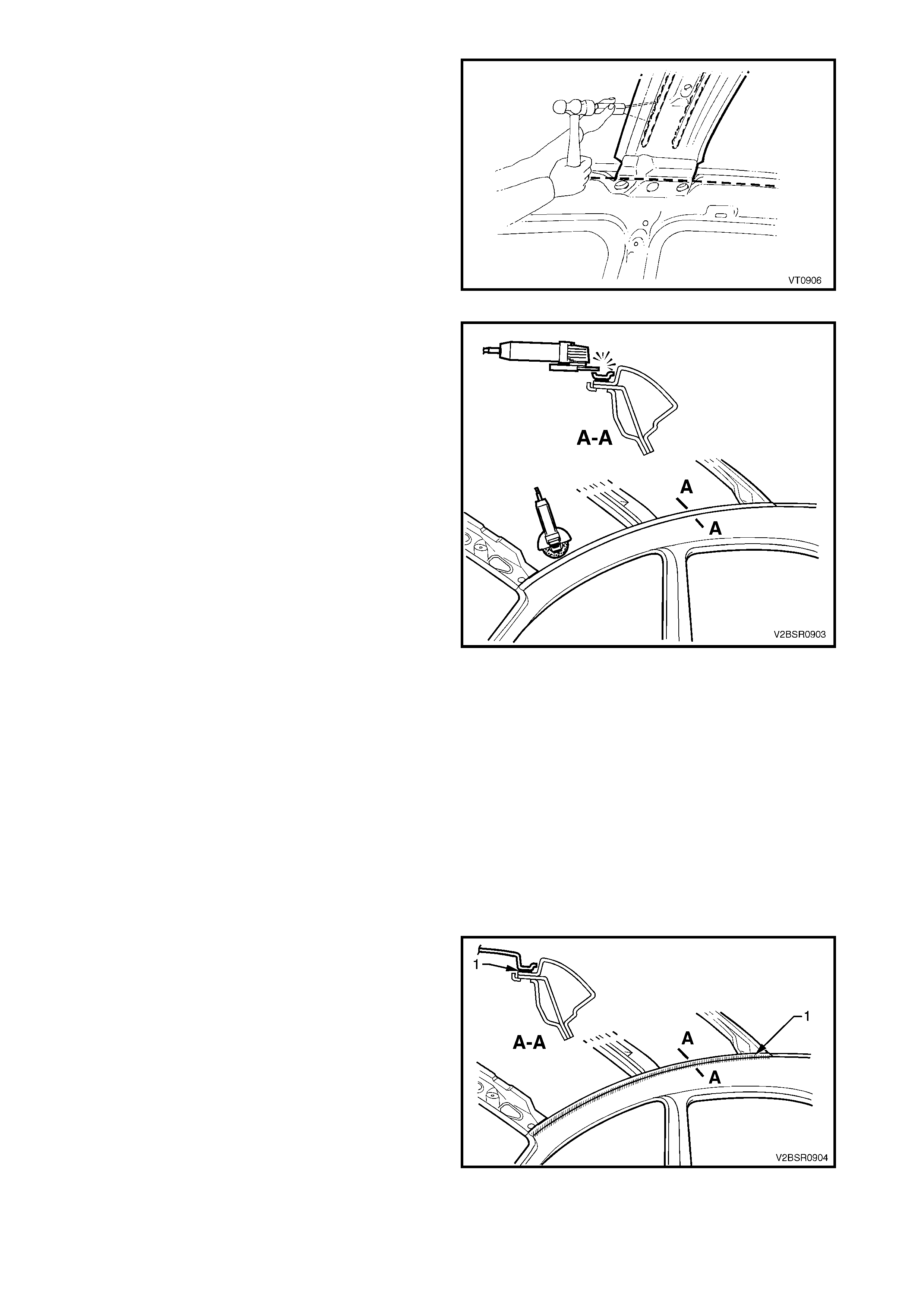
6. Cut through the softened adhesive between the
roof panel and roof front header panel, roof bow
panel and roof rear panel using a suitable tool.
7. Remove the roof panel from the vehicle.
Figure 9-6
8. Using an angle grinder, air chisel or other suitable
tool, rem ove the rem aining strip of roof panel from
the body side panel, along with the adhesive
beneath the strip.
9. Repair any damage to adjacent parts.
10. Check and rectify the alignment of the body as
required, refer to 3. BODY DIMENSIONS in
Section 3A.
Figure 9-7
REPLACE
NOTE 1: Spot welding is the preferred method for attaching of panels and should be used whenever possible.
Where the spot welding equipment will not access the required weld position, a plug weld should be performed.
NOTE 2: The s ame number and pos ition of s pot welds (or plug welds) s hould be used when r eplacing the panel,
as was used during manufacture, in order to maintain the original structural strength of the vehicle.
NOTE 3: When welding a relatively flat panel such as the roof panel, due care must be taken to minimise the
heat absorbed by the panel which could lead to panel distortion.
1. Clean the remaining Anti-flutter adhesive from the surfaces of the roof front header panel, roof bow panel
and roof rear panel.
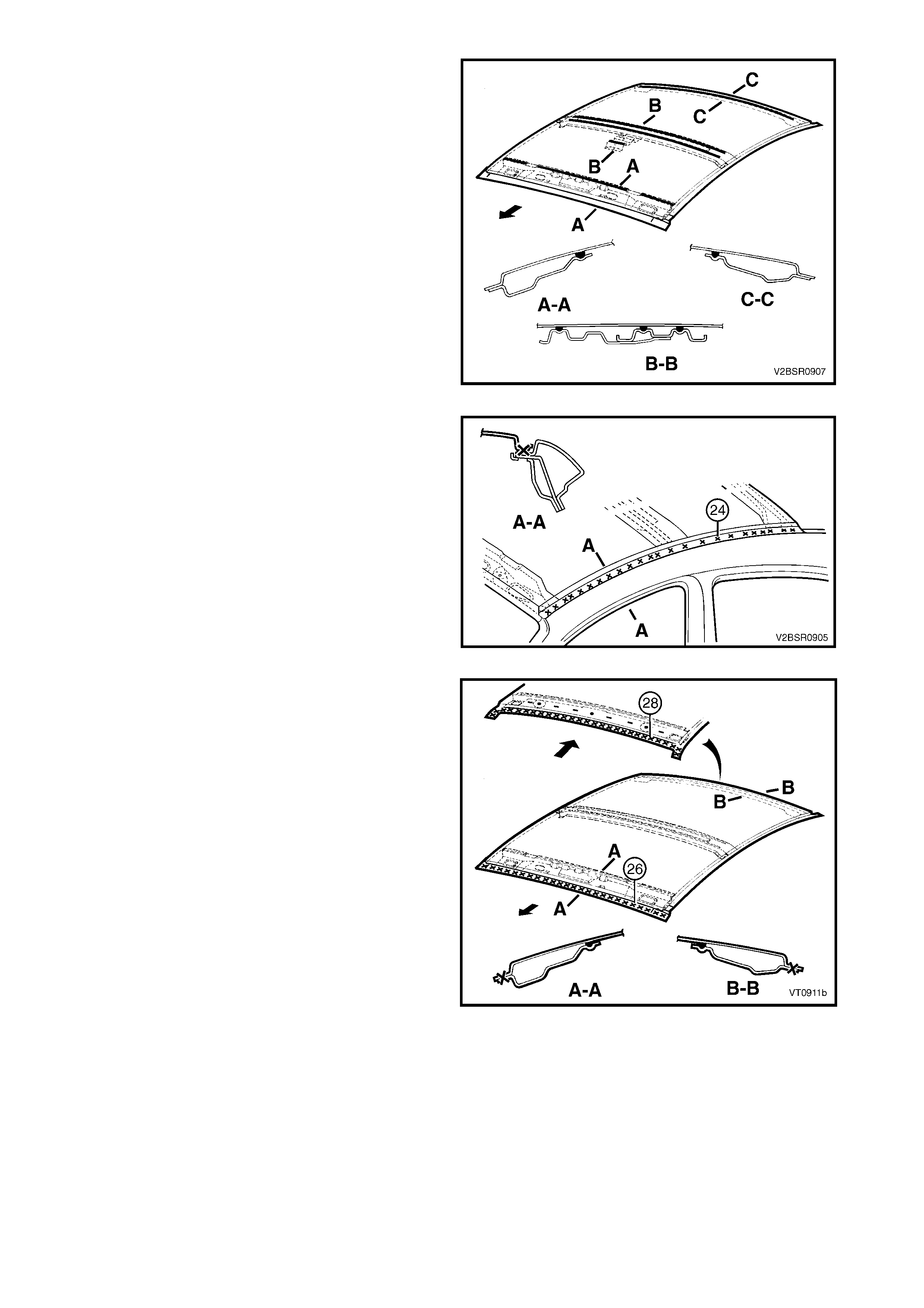
2. Prepare the mating surface areas for welding. Dress the channel flange area, the roof front header panel,
roof bow panel and roof rear panel as required so they are flat and free from imperfections.
3. As required, mark the new panel with drilling locations in preparation for plug welding. Drill holes as required.
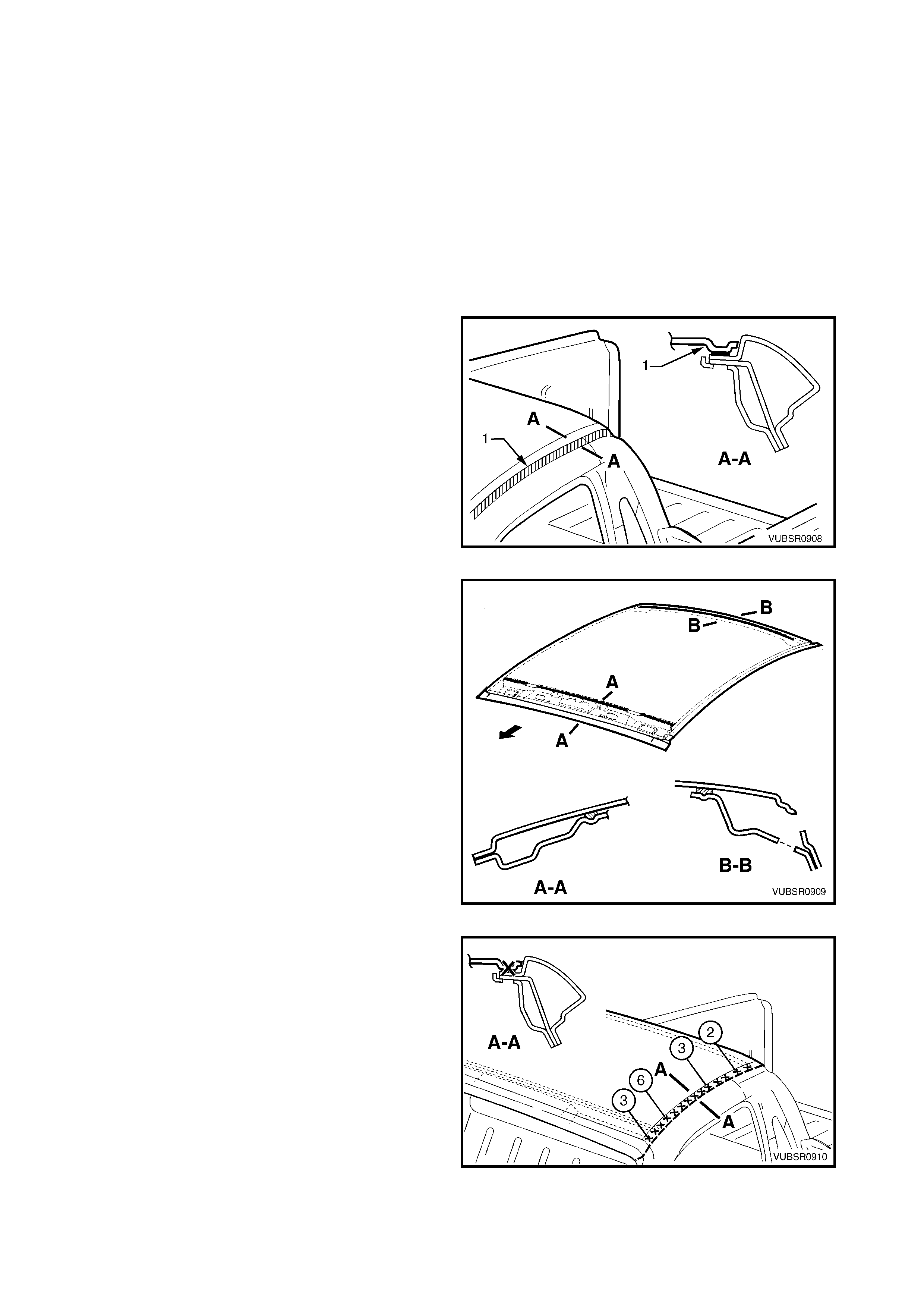
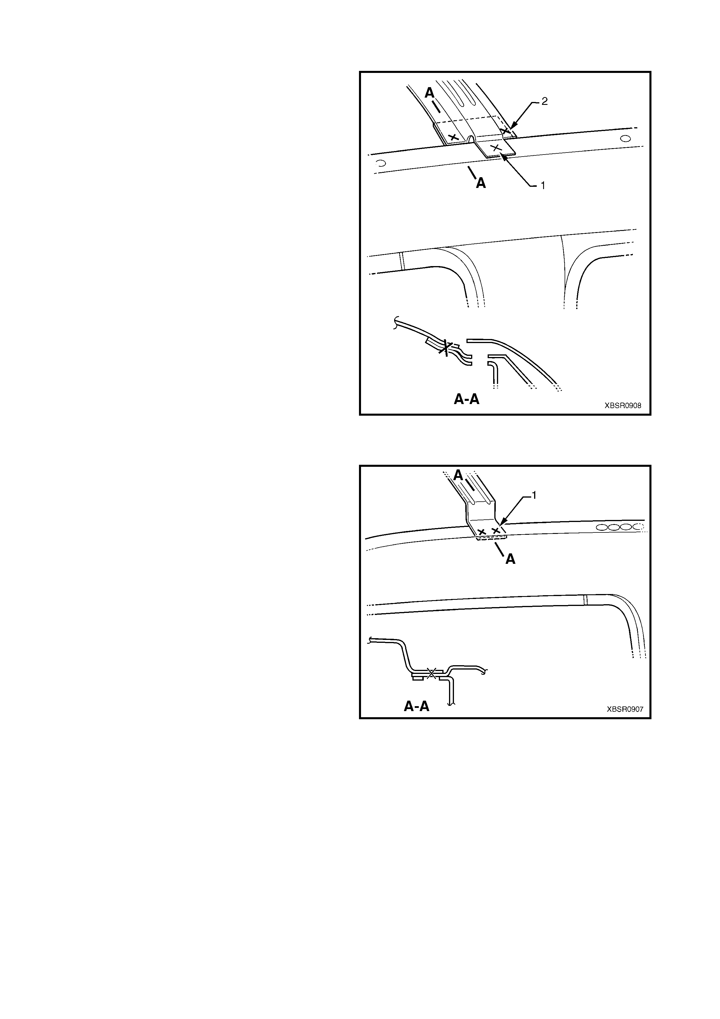
4. Apply Structural Adhesive (Item 6), refer to
5. BODY SEALING, ADHESIVES & DEAD ENERS
in Section 3A.
Figure 9-8
5. Apply a bead of Anti-flutter Adhesive (Item 5)
to the full length of the groove in the roof front
header panel and roof rear panel. Refer to
5. BODY SEALING, ADHESIVES & DEADENERS
in Section 3A.
6. Apply two full length beads of Anti-flutter adhesive
to the grooves in the roof bow panel.
7. Position the roof panel on the vehicle and clam p in
place.
Figure 9-9
8. Spot or plug weld the roof panel to the door
opening frame on both sides of the vehicle using
the same number of welds as per original build.
NOTE 1: Take care to minimise the heat absorbed by
the panel in order to reduce heat distortion.
NOTE 2: In some cases it may be advantageous to
begin welding from the middle of the run and weld
alternatively to the front and rear. This may reduce
panel distortion.
Figure 9-10
9. Spot or plug weld the roof panel to the roof front
header panel and roof rear panel using the same
number of welds as per original build.
10. Refinish and paint panels and other components
as required. Refer to Section 3, 1.3 PAINT
REFINISHING.
11. Apply Joint Sealer (Item 3) as required. Refer to
5. BODY SEALING, ADHESIVES & DEADENERS
in Section 3A.
12. Apply Cavity Wax (Item 8) as r equired to the inside
of any box sections or areas inaccessible to paint,
refer to 6. CAVITY WAX in Section 3A.
13. Replace the windshield and rear window, refer to
Section 1A6, STATIONARY GLASS in the
MY 2003 VY & V2 Series II Service Information.
14. Install the remaining components as described in
the appropriate Section of the MY 2003 VY & V2
Series II Service Information. Figure 9-11
2.2 ROOF PANEL, SEDAN, WITH SUNROOF – REPLACE
REMOVE
1. Remove the adjac ent trim and c omponents as des cr ibed in the appropr iate Sec tion of the MY 2003 VY & V2
Series II Service Information.
2. Remove the windshield and rear window, refer to Section 1A6, STATIONARY WINDOWS in the MY 2003
VY & V2 Series II Service Information.
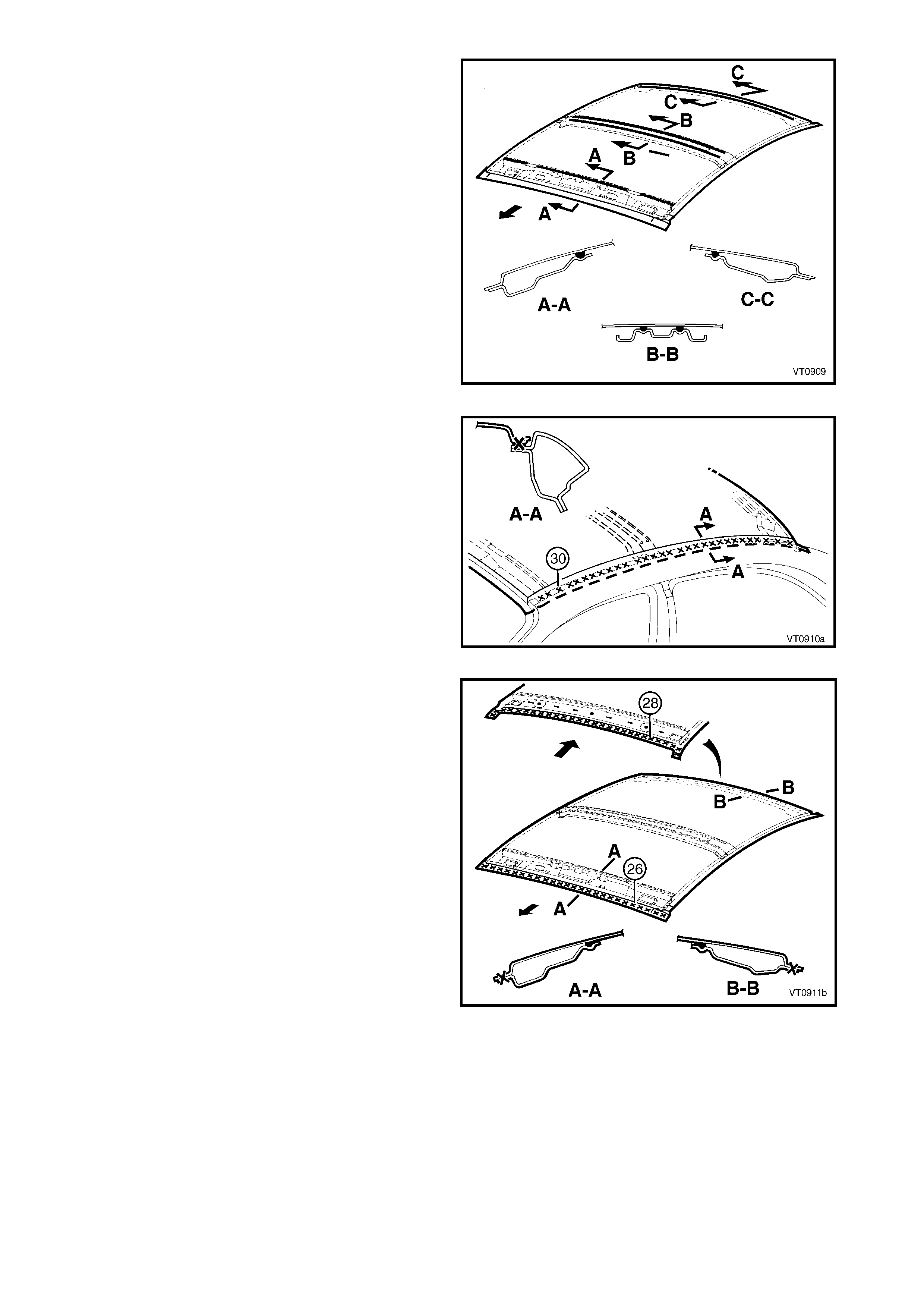
3. Spot cut the welds attaching the roof panel to the
windshield header rail and rear roof frame.
Figure 9-12
4. Using a cutting tool such as an air chisel or angle
grinder, cut through the roof panel along the side
of the roof channel.
NOTE 1: The sunroof housing must removed with the
roof panel.
NOTE 2: As the roof panel is securely glued to the
body side panel along the channel, it cannot be
removed by simply spot cutting the welds.
NOTE 3: If the roof front header panel and roof rear
panel are to be retained, take care not to cut them off
with the roof panel. Alternatively, if one or more are to
be replaced, it is eas ier to cut off those being replaced
along with the roof panel.
Figure 9-13
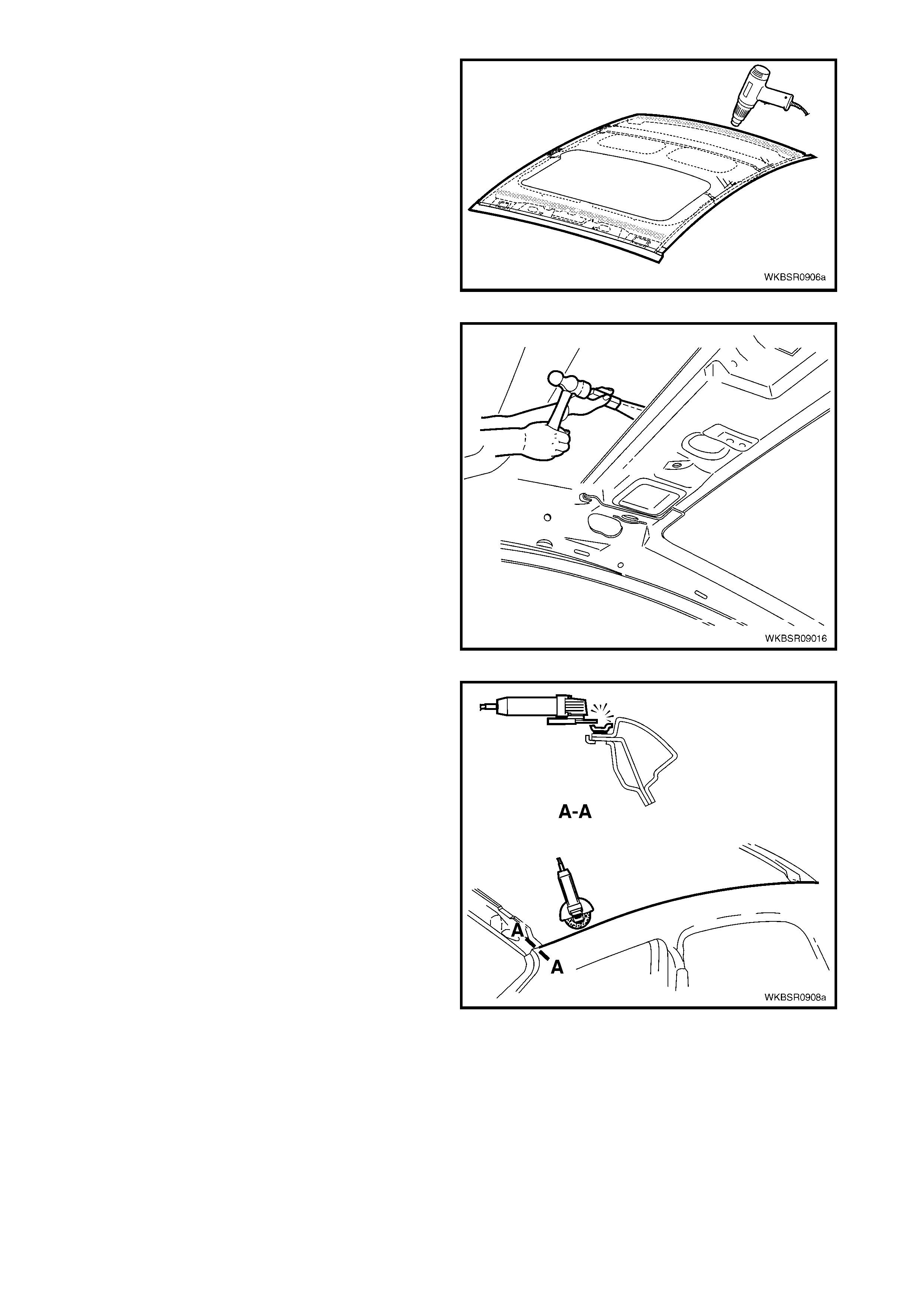
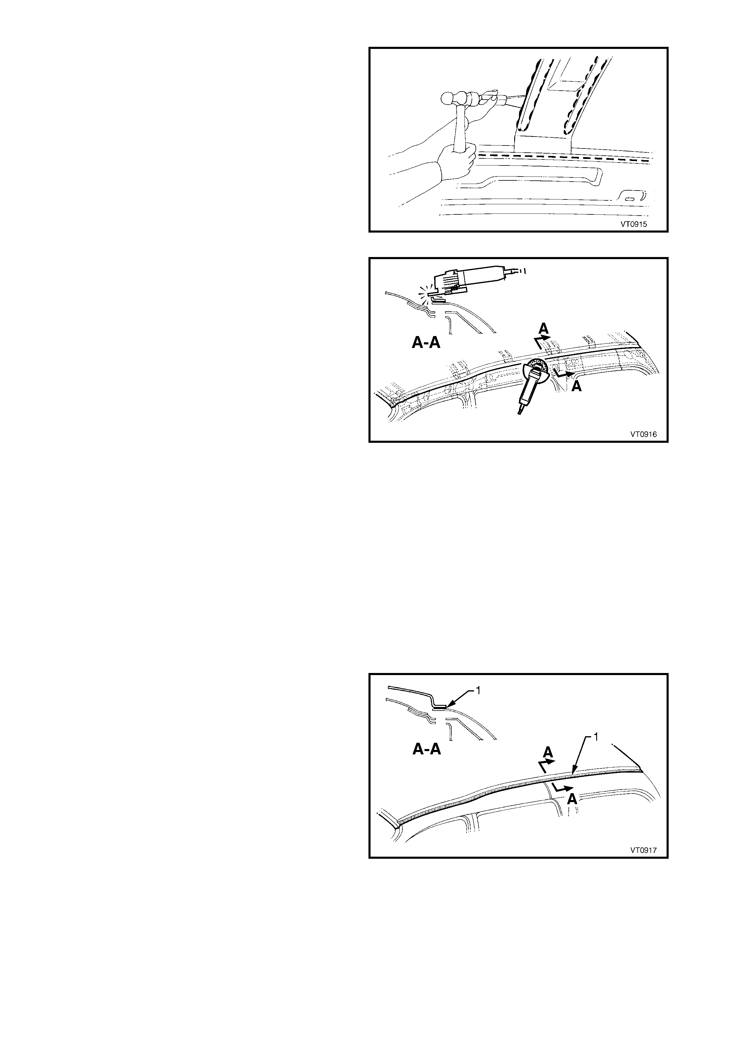
5. Use a heat gun to soften the Anti-flutter adhesive
between the roof front header panel and roof rear
panel by heating the areas shown.
Figure 9-14
6. Cut through the softened adhesive between the
roof panel, roof front header panel and roof rear
panel using a suitable tool.
7. Remove the roof panel from the vehicle.
Figure 9-15
8. Using an angle grinder, air chisel or other suitable
tool, remove the remaining strip of roof panel and
sunroof housing from the body side panel, along
with the adhesive beneath the strip.
9. Repair any damage to adjacent parts.
10. Check and rectify the alignment of the body as
required, refer to 3. BODY DIMENSIONS in
Section 3A.
Figure 9-16
REPLACE
NOTE 1: Spot welding is the preferred method for attaching of panels and should be used whenever possible.
Where the spot welding equipment will not access the required weld position, a plug weld should be performed.
NOTE 2: The s ame number and pos ition of s pot welds (or plug welds) s hould be used when replac ing the panel,
as was used during manufacture, in order to maintain the original structural strength of the vehicle.
NOTE 3: When welding a relatively flat panel such as the roof panel, due care must be taken to minimise the
heat absorbed by the panel which could lead to panel distortion.
1. Clean the remaining Anti-flutter adhesive from the surfaces of the roof front header panel and roof rear
panel.
2. Prepare the mating surface areas for welding. Dress the channel flange area, the roof front header panel
and roof rear panel as required so they are flat and free from imperfections.
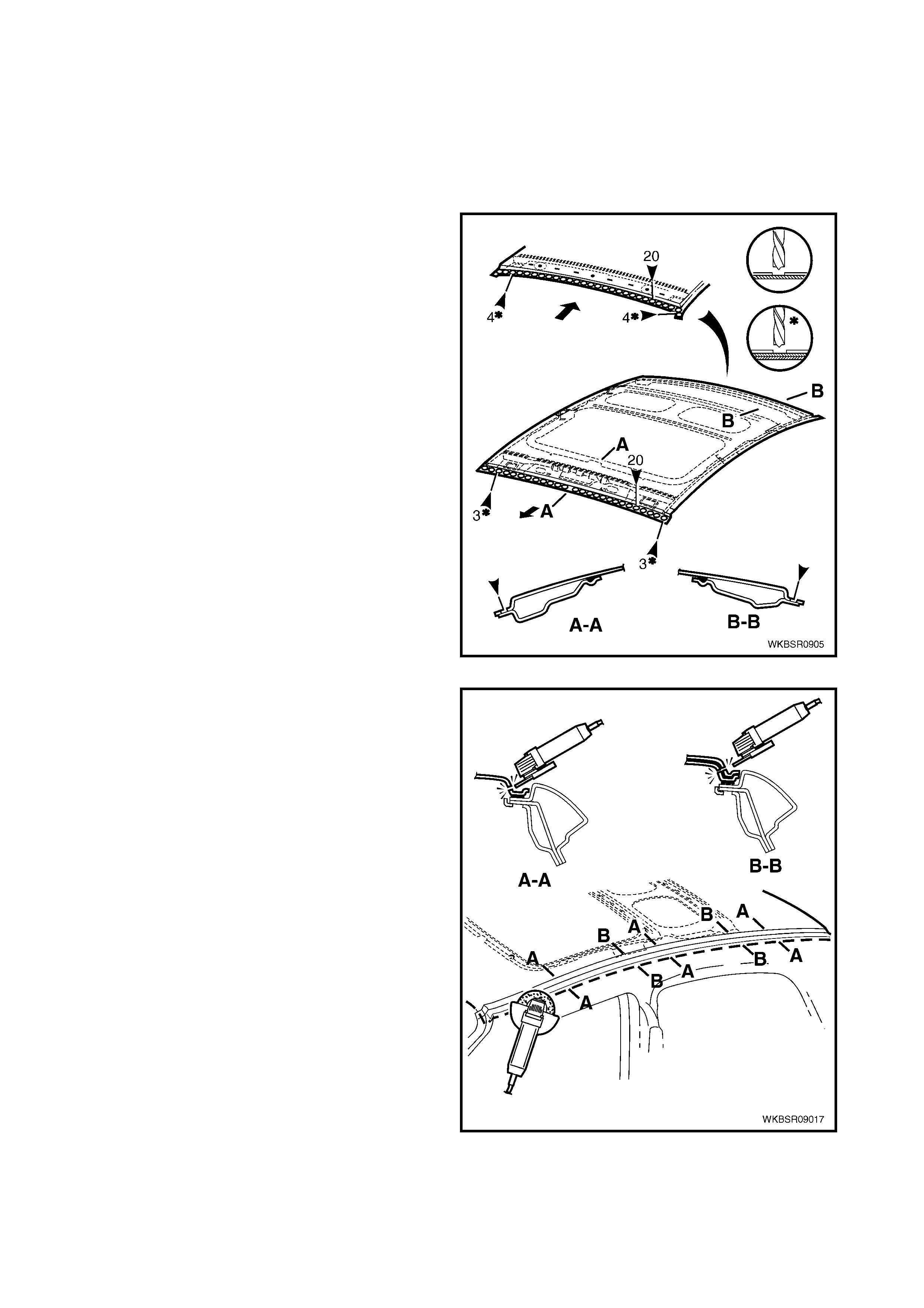
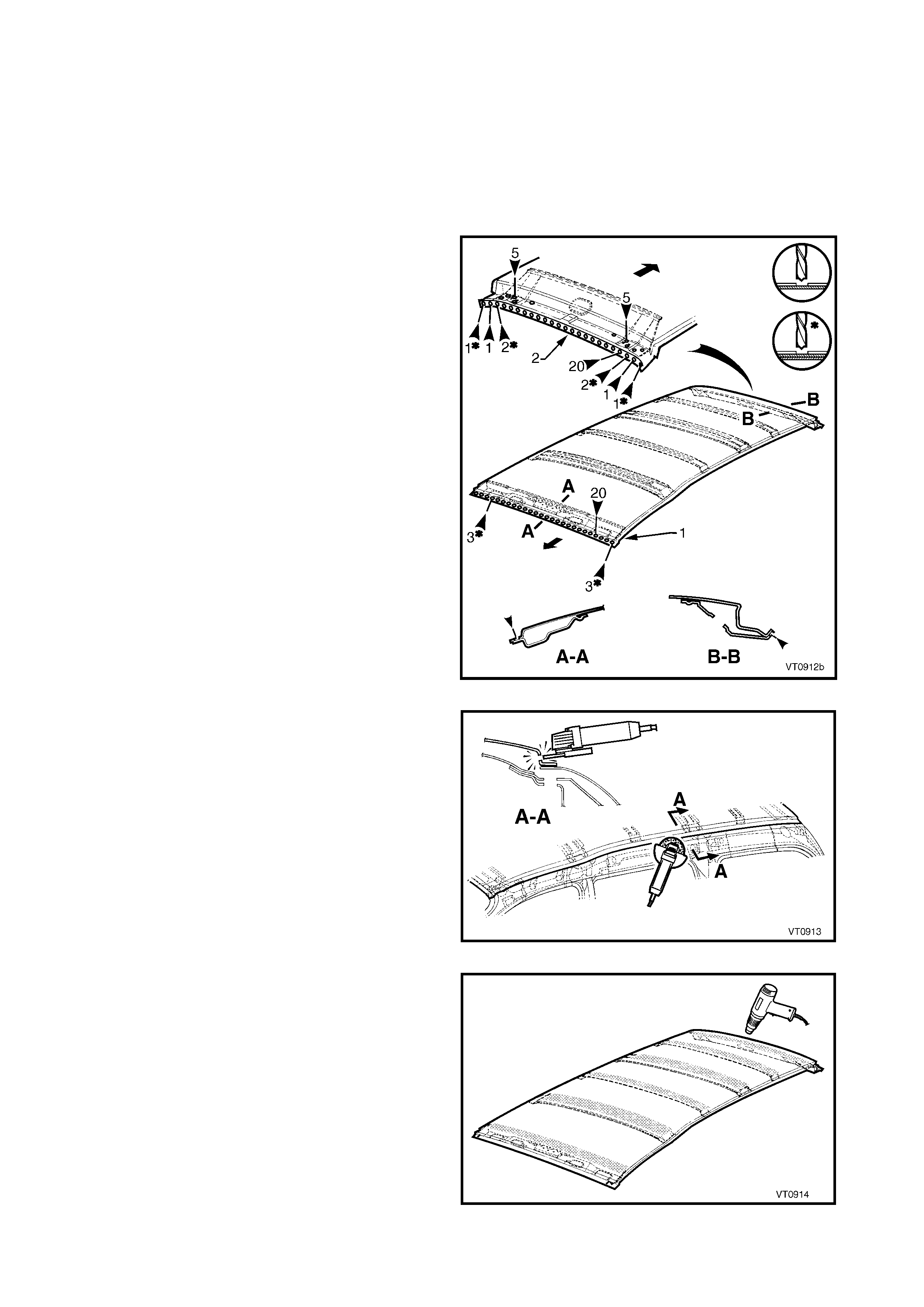
3. Treat the front and rear mating surfaces with Weld Through Primer (Item 1) as required. Refer to
5. BODY SEALING, ADHESIVES & DEADENERS in Section 3A.
4. As required, m ark the new roof panel with drilling locations, where plug welding is necessary. Drill holes as
required.
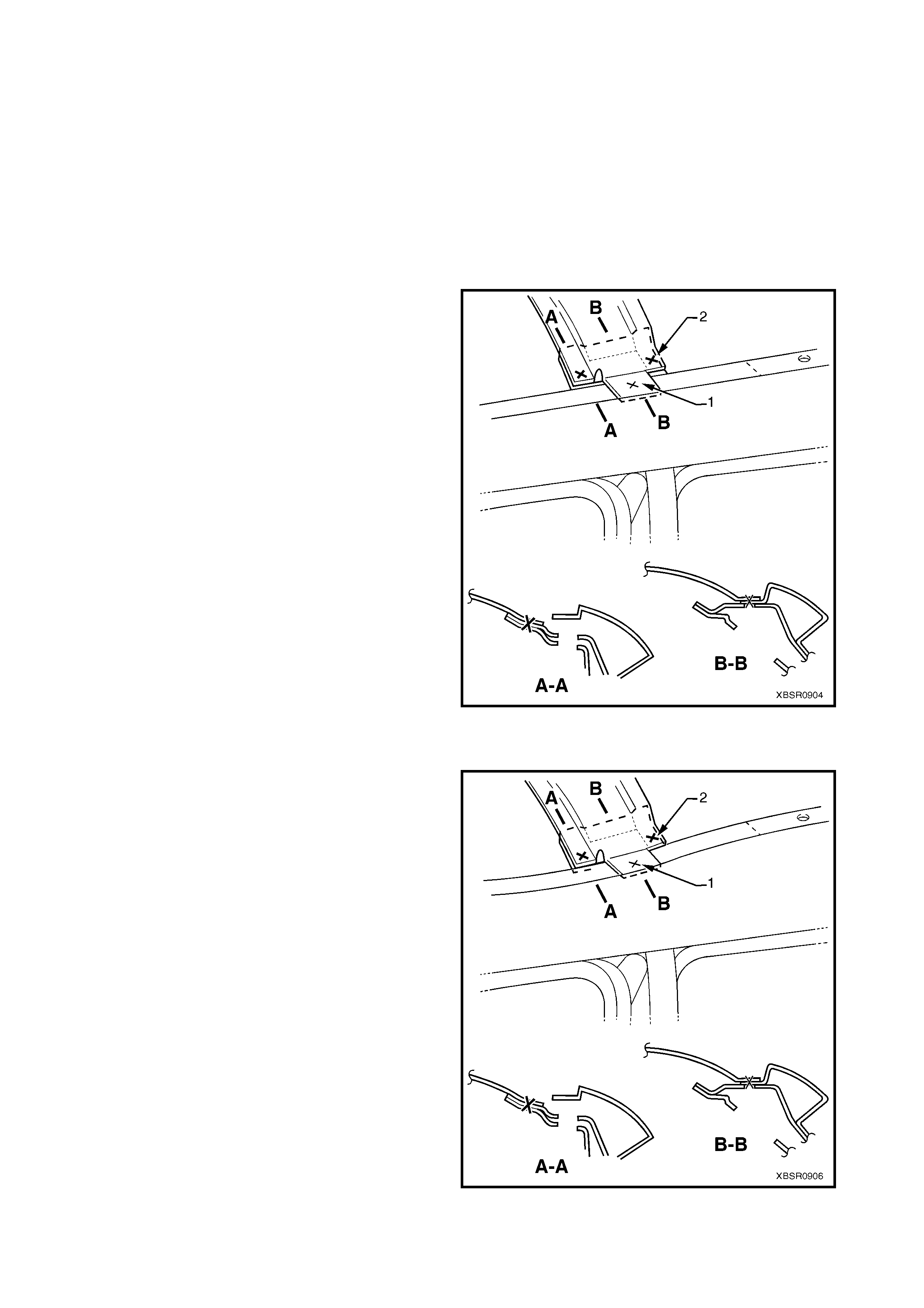
5. Apply a bead of Anti-flutter adhesive (Item 5) to the full length of the groove in the windshield header (section
A-A) and the groove in the rear roof frame (section B-B), refer to Figure 9-17.
Refer to 5. BODY SEALING, ADHESIVES & DEADENERS in Section 3A.
6. Apply two full length beads of Anti-flutter adhesive to the grooves in the roof supports (section B-B).
Figure 9-17
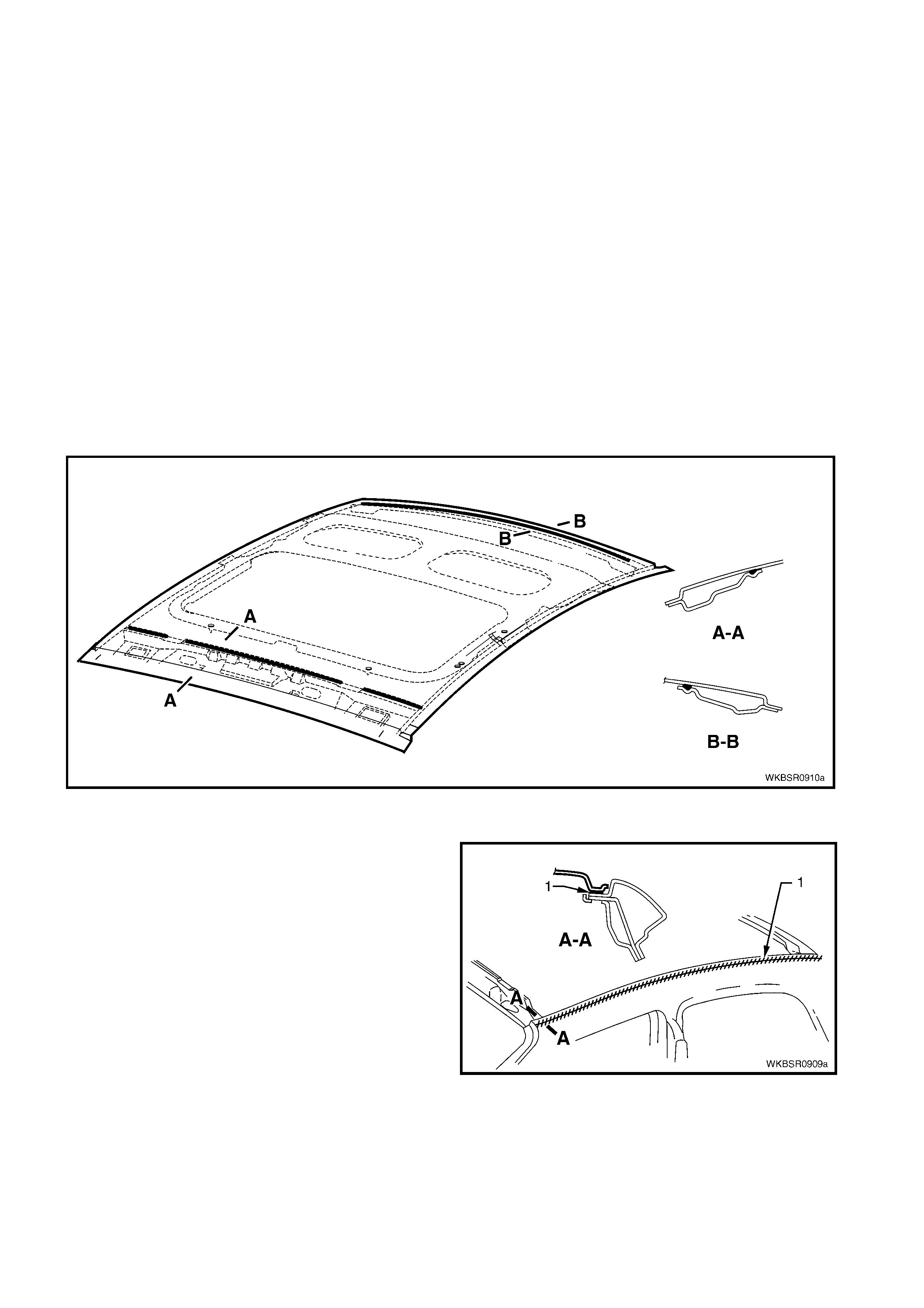
7. Apply Structural Adhesive (1) (Item 6), refer to
5. BODY SEALING, ADHESIVES & DEADENERS
in Section 3A.
8. Position the roof panel on the vehicle and clam p in
place.
Figure 9-18
9. Spot or plug weld the roof panel to the door
opening frame on both sides of the vehicle using
the same number of welds as per original build.
NOTE 1: Take care to minimise the heat absorbed by
the panel in order to reduce heat distortion.
NOTE 2: In some cases, especially if plug welding, it
may be advantageous to begin welding from the
middle of the r un and weld alternatively to the front and
rear. This may reduce panel distortion.
Figure 9-19
10. Spot or plug weld the roof panel to the roof front
header panel and roof rear panel using the same
number of welds as per original build.
11. Refinish and paint panels and other components
as required. Refer to Section 3, 1.3 PAINT
REFINISHING.
12. Apply Joint Sealer (Item 3) as required. Refer to
5. BODY SEALING, ADHESIVES & DEADENERS
in Section 3A.
13. Apply Cavity Wax (Item 8) as r equired to the inside
of any box sections or areas inaccessible to paint,
refer to 6. CAVITY WAX in Section 3A.
14. Replace the windshield and rear window, refer to
Section 1A6, Stationary Glass in the MY 2003
VY & V2 Series II Service Information.
15. Install the remaining components as described in
the appropriate Section of the MY 2003 VY & V2
Series II Service Information. Figure 9-20
2.3 ROOF PANEL, WAGON – REPLACE
REMOVE
1. Remove the adjac ent trim and c omponents as des cr ibed in the appropr iate Sec tion of the MY 2003 VY & V2
Series II Service Information.
2. Remove the windshield, r efer to Section 1A6, STAT IONARY WINDOWS in the MY 2003 VY & V2 Series II
Service Information.
3. Remove the liftgate, refer to Section 8, 2.6 LIFTGATE ASSEMBLY – REPLACE.
4. Spot cut the welds attaching the roof panel to the
roof front header panel (1) and roof rear panel (2).
Figure 9-21
5. Using a cutting tool such as an air chisel or angle
grinder, cut through the roof panel along the side
of the roof channel.
NOTE 1: As the roof panel is securely glued to the
body side panel along the channel it cannot be
removed by simply spot cutting the welds.
NOTE 2: If the roof front header panel, roof bow
panels and roof rear panel are to be retained, take
care not to cut them off with the roof panel.
Alternatively, if one or all are to be r eplac ed, it is easier
to cut those being replaced off with the roof panel.
Figure 9-22
6. Use a heat gun to soften the Anti-flutter adhesive
between the roof front header panel, roof bow
panels and roof rear panel by heating the areas
shown.
Figure 9-23
7. Cut through the softened adhesive between the
roof panel and roof front header panel, roof bow
panels and roof rear panel using a suitable tool.
8. Remove the roof panel from the vehicle.
Figure 9-24
9. Using an angle grinder, air chisel or other suitable
tool, rem ove the rem aining strip of roof panel from
the body side panel, along with the adhesive
beneath the strip.
10. Repair any damage to adjacent parts.
11. Check and rectify the alignment of the body as
required, refer to 3. BODY DIMENSIONS in
Section 3B.
Figure 9-25
REPLACE
NOTE 1: Spot welding is the preferred method for attaching of panels and should be used whenever possible.
Where the spot welding equipment will not access the required weld position, a plug weld should be performed.
NOTE 2: The s ame number and pos ition of s pot welds (or plug welds) s hould be used when r eplacing the panel,
as was used during manufacture, in order to maintain the original structural strength of the vehicle.
NOTE 3: When welding a relatively flat panel such as the roof panel, due care must be taken to minimise the
heat absorbed by the panel which could lead to panel distortion.
1. Clean any remaining Anti-flutter adhesive from the surface of the roof front header panel, roof bow panels
and roof rear panel.
2. Prepare the mating areas for welding. Dress the channel flange area, the roof front header panel, roof bow
panels and roof rear panel. These areas should be flat and free from imperfections.
3. As required, mark the new panel with drilling locations in preparation for plug welding. Drill holes as required.
4. Apply Structural Adhesive (Item 6), refer to
5. BODY SEALING, ADHESIVES & DEADENERS
in Section 3B.
Figure 9-26
5. Apply a bead of Anti-flutter Adhesive (Item 5)
to the full length of the groove in the roof front
header panel and roof rear panel. Refer to
5. BODY SEALING, ADHESIVES & DEADENERS
in Section 3B
6. Apply two full length beads of Anti-flutter adhesive
to the grooves in the roof bow panels.
7. Position the roof panel on the vehicle and clam p in
place.
8. Spot or plug weld the roof panel to the door
opening frame on both sides of the vehicle using
the same number of welds as the original
production build. Refer to Figure 9-28.
NOTE 1: Take care to minimise the heat absorbed by
the panel in order to reduce heat distortion.
NOTE 2: In some cases it may be advantageous to
begin welding from the middle of the run and weld
alternatively to the front and rear. This may reduce
panel distortion.
Figure 9-27
Figure 9-28
9. Spot or plug weld the roof panel to the roof front
header panel and roof rear panel using the same
number of welds as per original build.
10. Refinish and paint panels and other components
as required. Refer to Section 3, 1.3 PAINT
REFINISHING.
11. Apply Joint Sealer (Item 3) as required. Refer to
5. BODY SEALING, ADHESIVES & DEADENERS
in Section 3B.
12. Apply Cavity Wax (Item 8) as r equired to the inside
of any box sections or areas inaccessible to paint,
refer to 6. CAVITY WAX in Section 3B.
13. Replace the windshield, refer to Section 1A6,
STATIONARY GLASS in the MY 2003 VY & V2
Series II Service Information.
14. Install the liftgate, refer to Section 8, 2.6
LIFTGATE ASSEMBLY – REPLACE.
15. Install the remaining components as described in
the appropriate Section of the MY 2003 VY & V2
Series II Service Information.
Figure 9-29
2.4 ROOF PANEL, UTILITY – REPLACE
REMOVE
1. Remove the adjac ent tr im and components as des c ribed in the appr opr iate Sect ion of the MY 2003 VY & V2
Series II Service Information.
2. Remove the windshield and rear window, refer to Section 1A6, STATIONARY WINDOWS in the MY 2003
VY & V2 Series II Service Information.
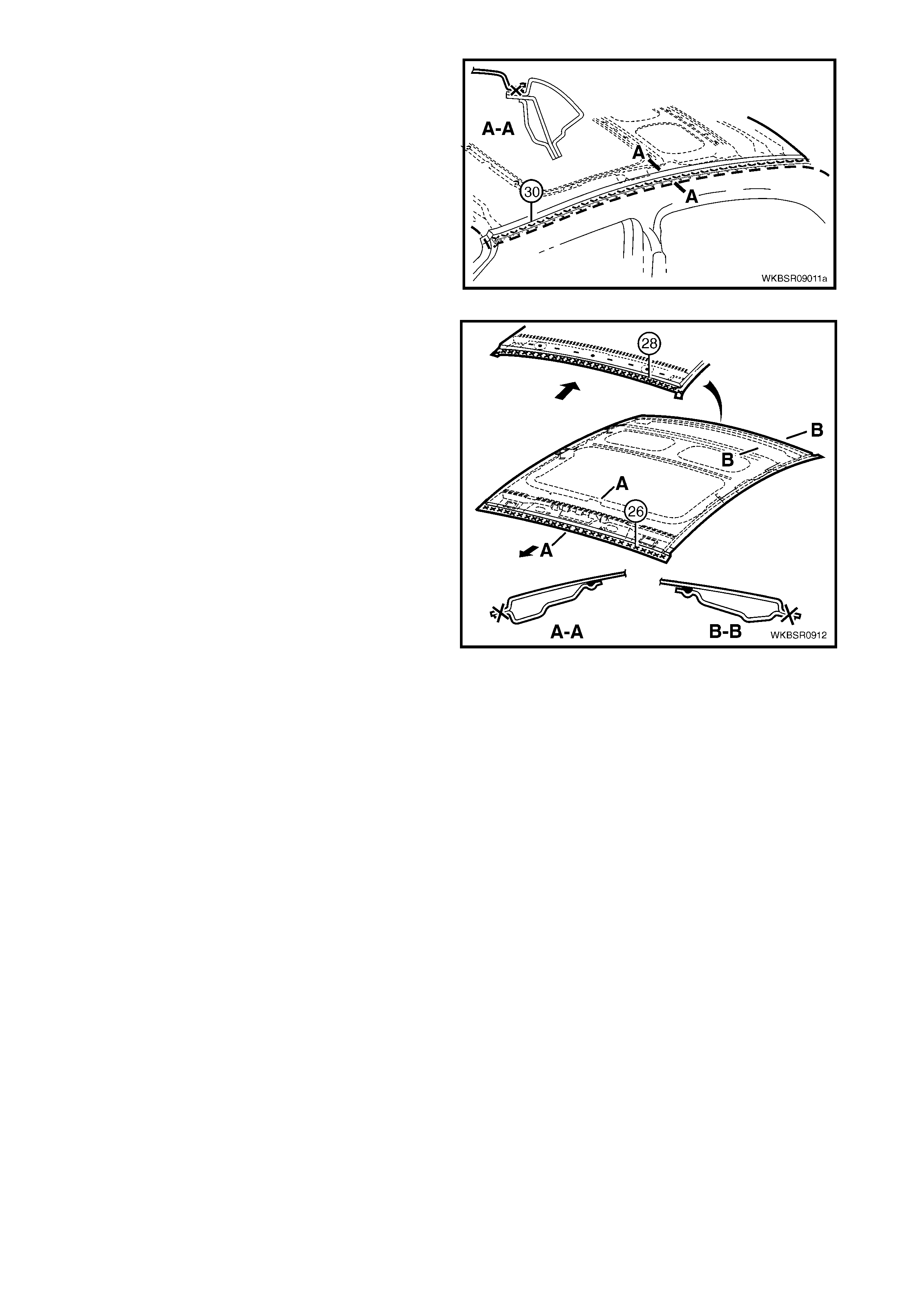
3. Spot cut the welds attaching the roof panel to the
roof front header panel.
Figure 9-30
4. Spot cut the welds attaching the roof panel to the
roof rear panel.
5. Spot cut the 3 welds each side attaching the roof
panel to the door opening frame and side inner
upper front panel.
Figure 9-31
6. Using a cutting tool such as an air chisel or angle
grinder, cut through the roof panel along the side
of the roof channel.
NOTE 1: As the roof panel is securely glued to the
body side panel along the channel it cannot be
removed by simply spot cutting the welds.
NOTE 2: If the roof front header panel and roof rear
panel are to be retained, take care not to cut them off
with the roof panel. Alternatively, if one or more are to
be replac ed, it is easier to c ut of f thos e being replac ed,
along with the roof panel.
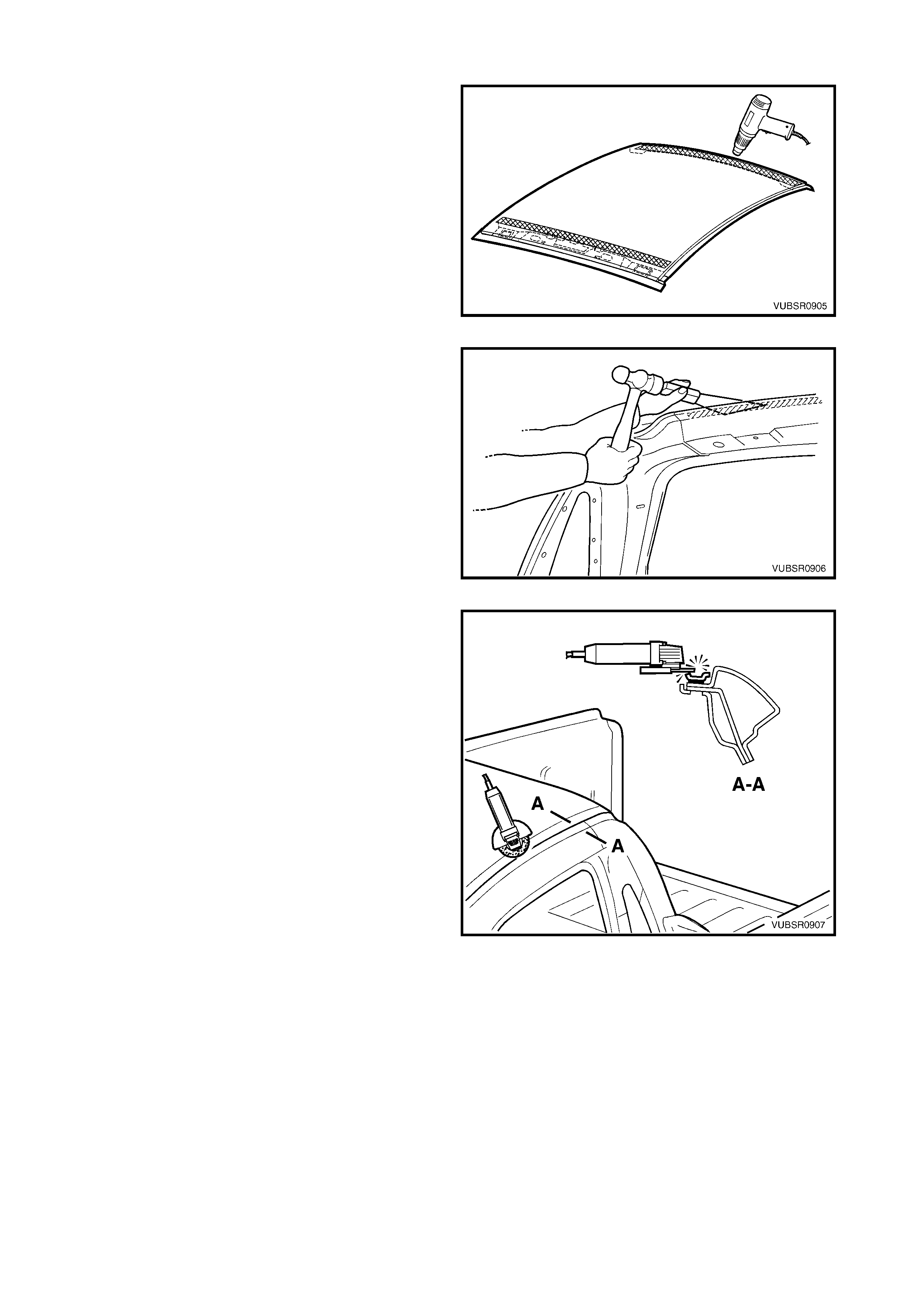
Figure 9-32
7. Use a heat gun to soften the Anti-flutter adhesive
between the roof panel and the roof front header
panel and roof rear panel by heating the areas
shown.
Figure 9-33
8. Cut through the softened adhesive between the
roof panel and the r oof f ront header panel and roof
rear panel using a suitable tool.
9. Remove the roof panel from the vehicle.
Figure 9-34
10. Using an angle grinder, air chisel or other suitable
tool, rem ove the rem aining strip of roof panel from
the body side panel, along with the adhesive
beneath the strip.
11. Repair any damage to adjacent parts.
12. Check and rectify the alignment of the body as
required, refer to 3. BODY DIMENSIONS in
Section 3C.
Figure 9-35
REPLACE
NOTE 1: Spot welding is the preferred method for attaching of panels and should be used whenever possible.
Where the spot welding equipment will not access the required weld position, a plug weld should be performed.
NOTE 2: The s ame number and pos ition of s pot welds (or plug welds) s hould be used when r eplacing the panel,
as was used during manufacture, in order to maintain the original structural strength of the vehicle.
NOTE 3: When welding a relatively flat panel such as the roof panel, due care must be taken to minimise the
heat absorbed by the panel which could lead to panel distortion.
1. Clean the remaining Anti-flutter adhesive from the surfaces of the roof front header panel and roof rear
panel.
2. Prepare the mating surface areas for welding. Dress the channel flange area, the roof front header panel
and roof rear panel as required so they are flat and free from imperfections.
3. As required, mark the new panel with drilling locations in preparation for plug welding. Drill holes as required.
4. Apply Structural Adhesive (Item 6) (1), refer to
5. BODY SEALING, ADHESIVES & DEAD ENERS
in Section 3C.
Figure 9-36
5. Apply a bead of Anti-flutter Adhesive (Item 5)
to the full length of the groove in the roof front
header panel and roof rear panel. Refer to
5. BODY SEALING, ADHESIVES & DEADENERS
in Section 3C
6. Pos ition the roof panel on the vehicle and clam p in
place.
Figure 9-37
7. Spot or plug weld the roof panel to the door
opening frame on both sides of the vehicle using
the same number of welds as per original build.
NOTE 1: Take care to minimise the heat absorbed by
the panel in order to reduce heat distortion.
NOTE 2: In some cases it may be advantageous to
begin welding from the middle of the run and weld
alternatively to the front and rear. This may reduce
panel distortion.
8. Spot or plug weld the roof panel to the roof front
header panel, roof rear panel and the door
opening frame and side inner upper front panel
each side, refer to Figure 9-39.
Figure 9-38
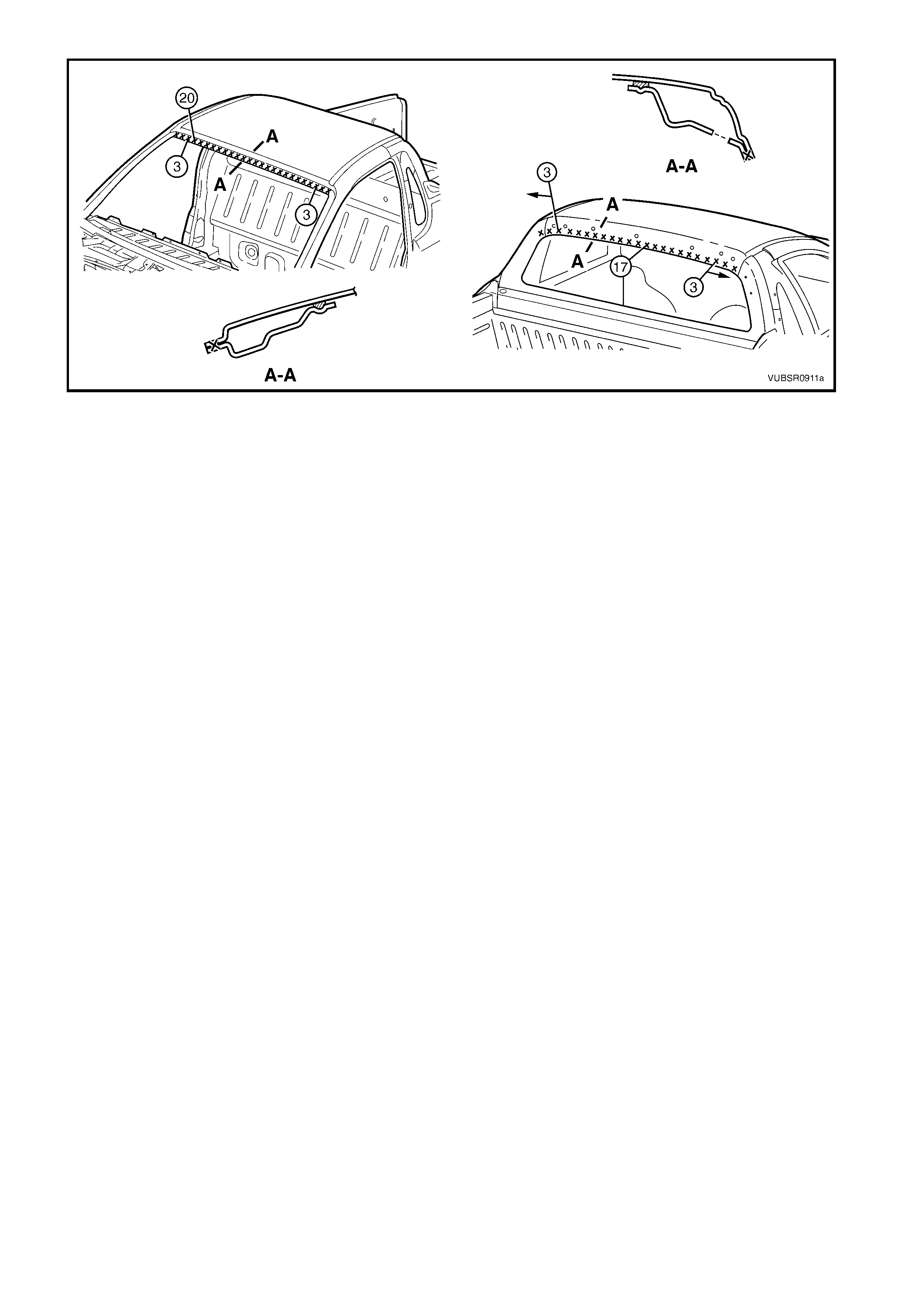
Figure 9-39
9. Refinish and paint panels and other components as required. Refer to Section 3, 1.3 PA INT REFINISHING.
10. Apply Joint Sealer (Item 3) as required. Refer to 5. BODY SEALING, ADHESIVES & DEADENERS in
Section 3C.
11. Apply Cavity W ax ( Item 8) as r equired to the inside of any box sections or areas inac cessible to paint, ref er
to 6. CAVITY WAX in Section 3C.
12. Replace the windshield and rear window, refer to Section 1A6, STAT IO NARY GLASS in the MY 2003 VY &
V2 Series II Service Information.
13. Install the r emaining com ponents as desc ribed in the appropriate Section of the MY 2003 VY & V2 Series II
Service Information.
2.5 ROOF PANEL, COUPE – REPLACE
REMOVE
1. Remove the adjac ent trim and c omponents as des cr ibed in the appropr iate Sec tion of the MY 2003 VY & V2
Series II Service Information.
2. Remove the windshield and rear window, refer to Section 1A6, STATIONARY WINDOWS in the MY 2003
VY & V2 Series II Service Information.
3. Spot cut the welds attaching the roof panel to the
roof front header panel and roof rear panel.
Figure 9-40
4. Using a cutting tool such as an air chisel or angle
grinder, cut through the roof panel along the side
of the roof channel.
NOTE 1: As the roof panel is securely glued to the
body side panel along the channel it cannot be
removed by simply spot cutting the welds.
NOTE 2: If the roof front header panel, roof bow panel
and roof r ear panel are to be retained, tak e care not to
cut them off with the roof panel. Alternatively, if one or
more are to be replaced, it is easier to cut off those
being replaced, along with the roof panel.
Figure 9-41
5. Use a heat gun to soften the Anti-flutter adhesive
between the roof front header panel, roof bow
panel and roof rear panel, by heating the areas
shown.
Figure 9-42
6. Cut through the softened adhesive between the
roof panel and roof front header panel, roof bow
panel and roof rear panel using a suitable tool.
7. Remove the roof panel from the vehicle.
Figure 9-43
8. Using an angle grinder, air chisel or other suitable
tool, rem ove the rem aining strip of roof panel from
the body side panel, along with the adhesive
beneath the strip.
9. Repair any damage to adjacent parts.
10. Check and rectify the alignment of the body as
required, refer to 3. BODY DIMENSIONS in
Section 3D.
Figure 9-44
REPLACE
NOTE 1: Spot welding is the preferred method for attaching of panels and should be used whenever possible.
Where the spot welding equipment will not access the required weld position, a plug weld should be performed.
NOTE 2: The s ame number and pos ition of s pot welds (or plug welds) s hould be used when r eplacing the panel,
as was used during manufacture, in order to maintain the original structural strength of the vehicle.
NOTE 3: When welding a relatively flat panel such as the roof panel, due care must be taken to minimise the
heat absorbed by the panel which could lead to panel distortion.
1. Clean the remaining Anti-flutter adhesive from the surfaces of the roof front header panel, roof bow panel
and roof rear panel.
2. Prepare the mating surface areas for welding. Dress the channel flange area, the roof front header panel,
roof bow panel and roof rear panel as required so they are flat and free from imperfections.
3. As required, mark the new panel with drilling locations in preparation for plug welding. Drill holes as required.
4. Apply Structural Adhesive (Item 6), refer to
5. BODY SEALING, ADHESIVES & DEAD ENERS
in Section 3D.
Figure 9-45
5. Apply a bead of Anti-flutter Adhesive (Item 5)
to the full length of the groove in the roof front
header panel and roof rear panel. Refer to
5. BODY SEALING, ADHESIVES & DEAD ENERS
in Section 3D.
6. Apply two full length beads of Anti-flutter adhesive
to the grooves in the roof bow panel.
7. Pos ition the roof panel on the vehicle and clam p in
place.
Figure 9-46
8. Spot or plug weld the roof panel to the door
opening frame on both sides of the vehicle using
the same number of welds as per original build.
NOTE 1: Take care to minimise the heat absorbed by
the panel in order to reduce heat distortion.
NOTE 2: In some cases it may be advantageous to
begin welding from the middle of the run and weld
alternatively to the front and rear. This may reduce
panel distortion.
Figure 9-47
9. Spot or plug weld the roof panel to the roof front
header panel and roof rear panel using the same
number of welds as per original build.
10. Refinish and paint panels and other components
as required. Refer to Section 3, 1.3 PAINT
REFINISHING.
11. Apply Joint Sealer (Item 3) as required. Refer to
5. BODY SEALING, ADHESIVES & DEADENERS
in Section 3D.
12. Apply Cavity Wax (Item 8) as r equired to the inside
of any box sections or areas inaccessible to paint,
refer to 6. CAVITY WAX in Section 3D.
13. Replace the windshield and rear window, refer to
Section 1A6, STATIONARY GLASS in the
MY 2003 VY & V2 Series II Service Information.
14. Install the remaining components as described in
the appropriate Section of the MY 2003 VY & V2
Series II Service Information. Figure 9-48
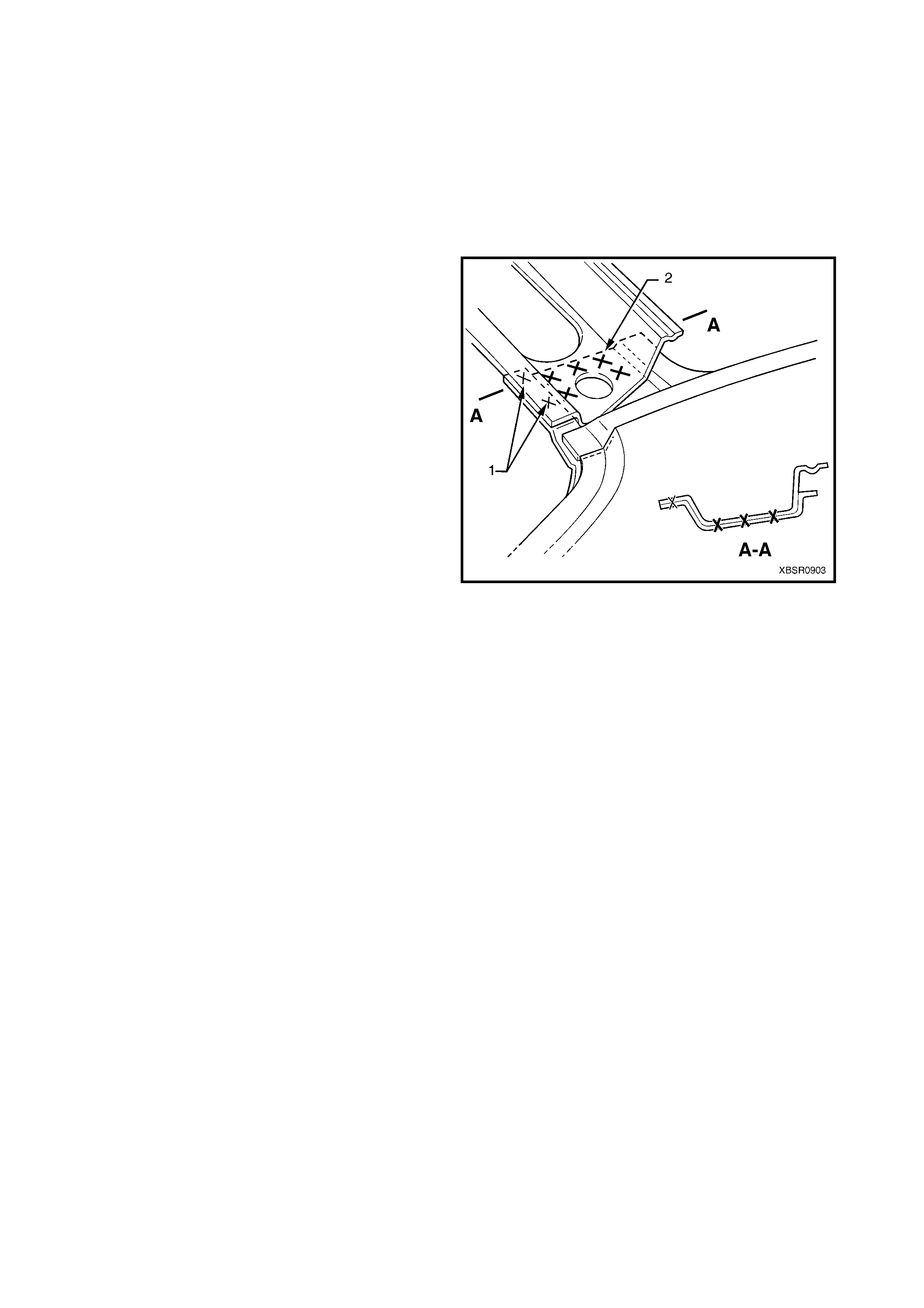
2.6 ROOF FRONT HEADER PANEL – REPLACE
Following removal of the roof panel, as required spot cut the welds attaching the roof front header panel as
shown in the following diagram.
W hen installing a roof front header panel, either spot weld the part to the vehicle or m ark and drill the new part
with holes in preparation for plug welding. The number of spot or plug welds must match the number shown in
the appropriate diagram.
Before fitting the part, prepare the mating surfaces and treat with Weld Through Primer (Item 1) as required,
refer to 5. BODY SEALING, ADHESIVES & DEADENERS in Section 3A (Sedan), Section 3B (Wagon),
Section 3C (Utility) or Section 3 D (Coupe).
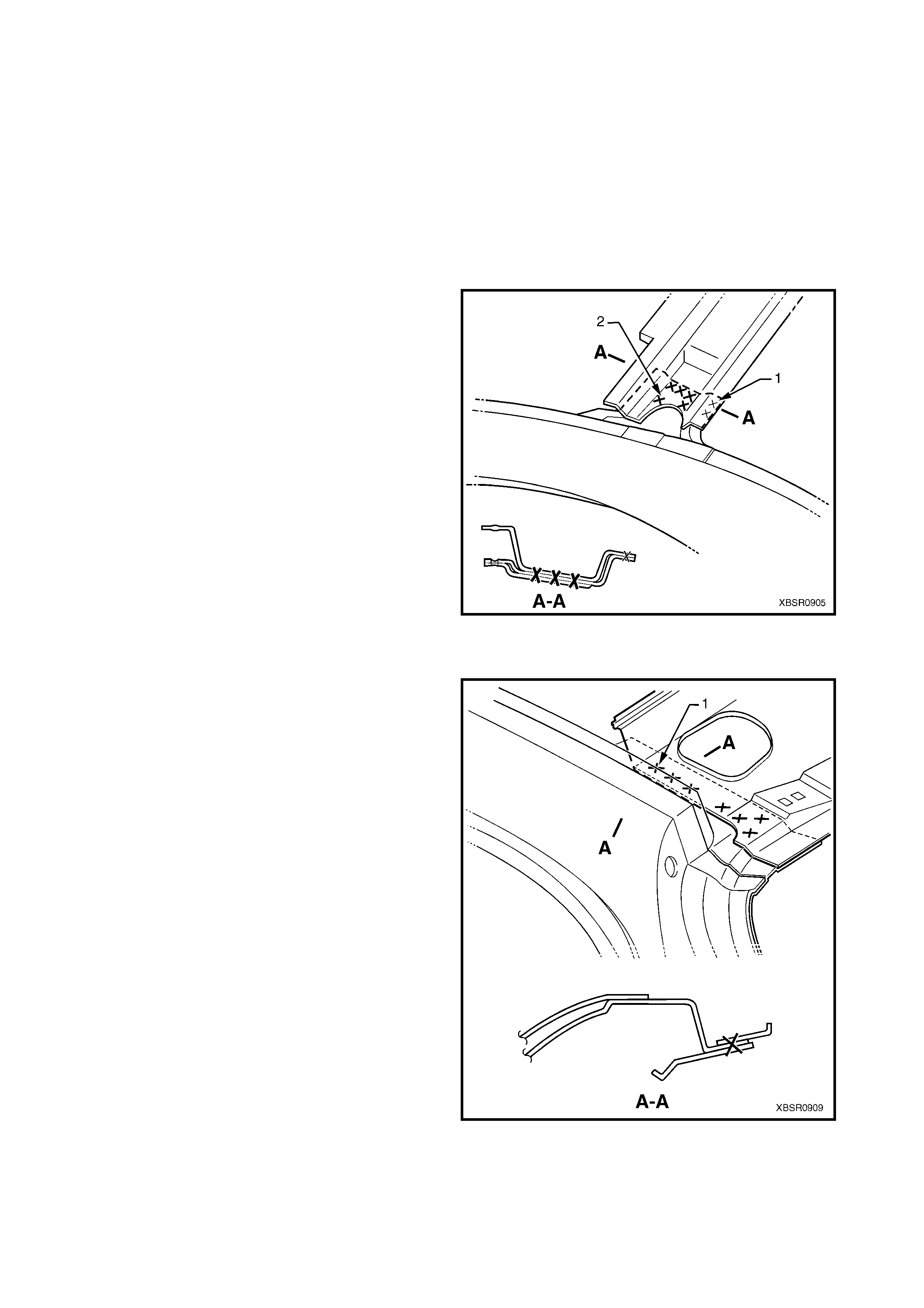
The two spot welds (1) are removed with the roof
panel.
Remove the five spot welds (2) from each side of the
vehicle to remove the roof front header panel.
Figure 9-49
2.7 ROOF BOW PANELS – REPLACE
Following removal of the roof panel, as required spot cut the welds attaching the roof bow panels as shown in
the following diagrams.
When installing a roof bow panel, either spot weld the part to the vehicle or mark and drill the new part with holes
in preparation for plug welding. The number of spot or plug welds must match the number shown in the
appropriate diagram.
Before fitting the part, prepare the mating surfaces and treat with Weld Through Primer (Item 1) as required,
refer to 5. BODY SEALING, ADHESIVES & DEADENERS in Section 3A (Sedan), Section 3B (Wagon) or
Section 3D (Coupe).
SEDAN & COUPE
The spot weld (1) is removed with the roof panel.
Remove the two spot welds (2) from each side of the
vehicle to remove the roof bow panel.
Figure 9-50
WAGON, ROOF BOW PANEL NO. 1
The spot weld (1) is removed with the roof panel.
Remove the two spot welds (2) from each side of the
vehicle to remove the roof bow panel No. 1.
Figure 9-51
2.8 ROOF REAR PANEL – REPLACE
Following rem oval of the roof panel, as r equired spot c ut the welds attaching the roof rear panel as shown in the
following diagrams.
When installing a roof rear panel, either spot weld the part to the vehicle or mark and drill the new part with holes
in preparation for plug welding. The number of spot or plug welds must match the number shown in the
appropriate diagram.
Before fitting the part, prepare the mating surfaces and treat with Weld Through Primer (Item 1) as required,
refer to 5. BODY SEALING, ADHESIVES & DEADENERS in Section 3A (Sedan), Section 3B (Wagon),
Section 3C (Utility) or Section 3D (Coupe).
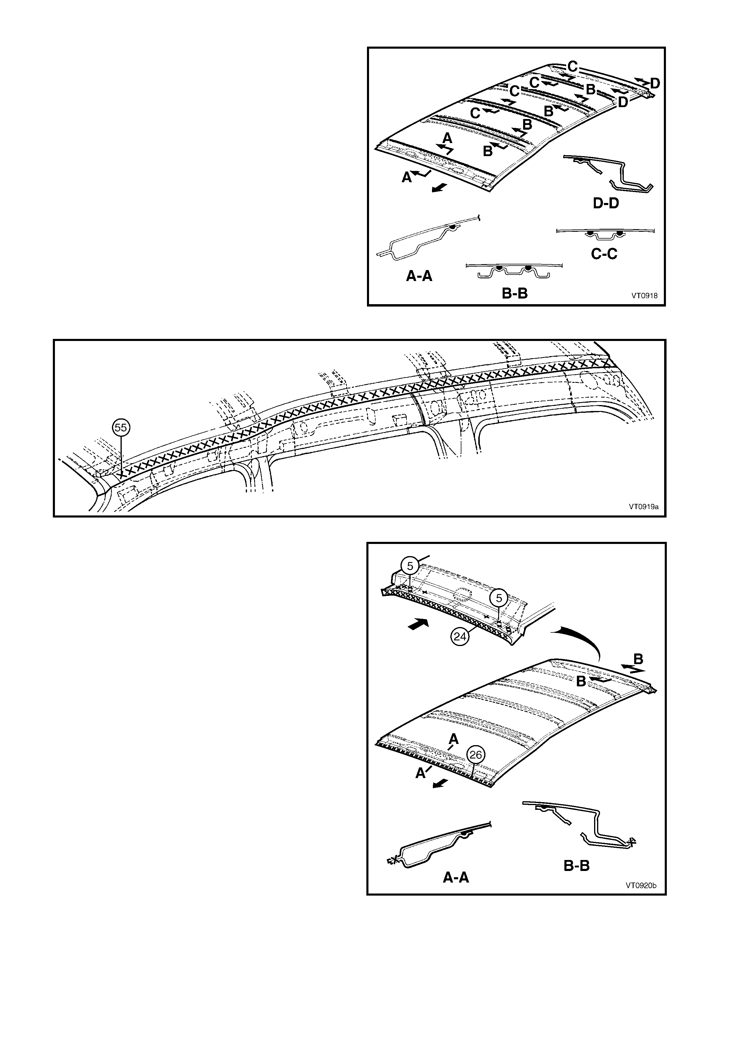
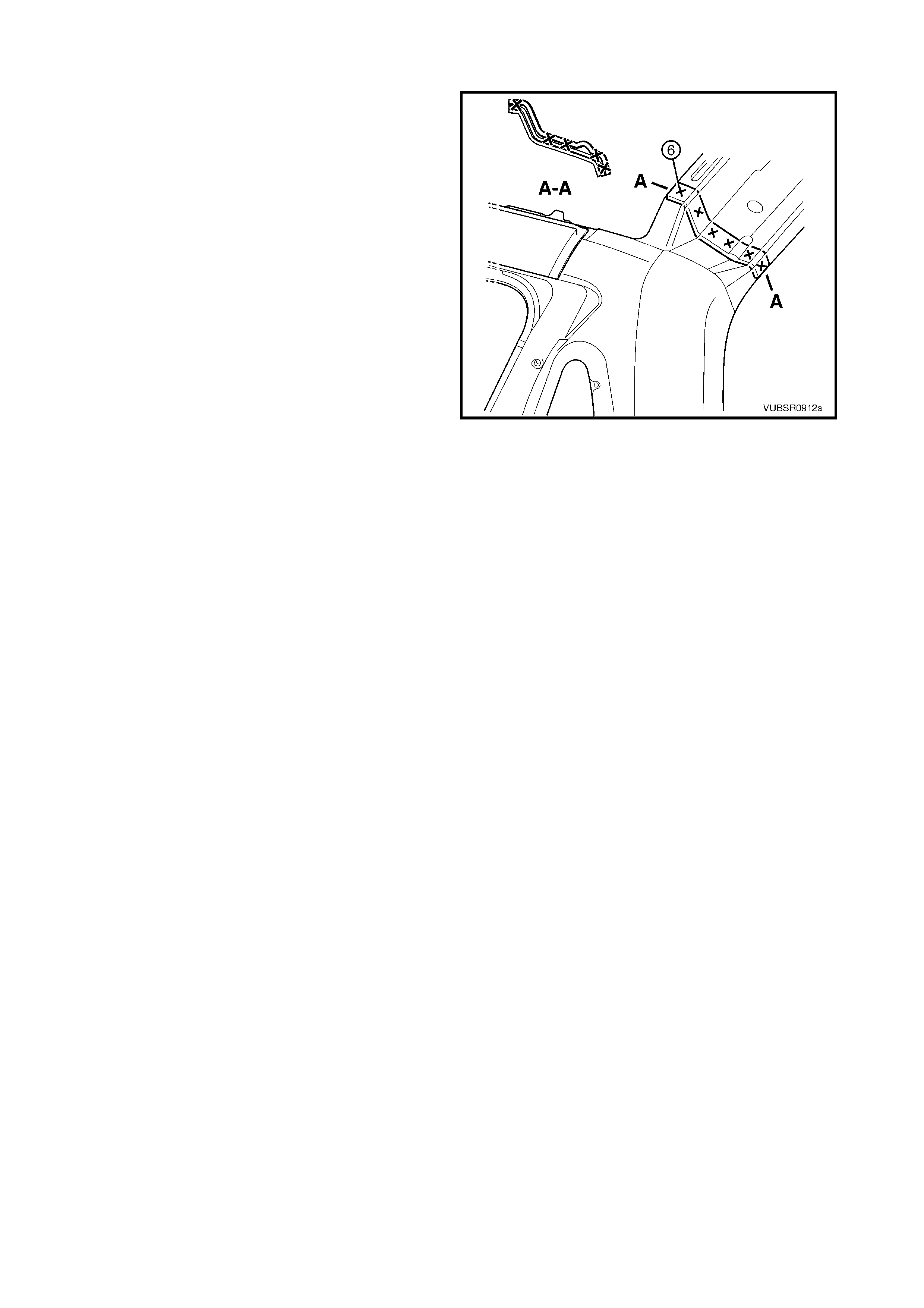
SEDAN & COUPE
The two spot welds (1) are removed with the roof
panel.
Remove the five spot welds (2) from each side of the
vehicle to remove the roof rear panel.
Figure 9-54
WAGON
Remove the seven spot welds (1) from each side of
the vehicle to remove the roof rear panel.
Figure 9-55
UTILITY
Remove the five spot welds from each side of the
vehicle to remove the roof rear panel.
Figure 9-56