
SECTION 10A – BODY REAR – SEDAN
IMPORTANT
Before performing any Service Operation or other procedure described in this Section, refer to
Section 00 CAUTIONS AND NOTES and Section 2 PRECAUTIONS in this Supplement for correct
workshop practices with regard to safety and/or property damage.
CAUTION
The Structure of the M Y 2003 VY & V2 Series II body shell has been developed using complex design
and development techniques. In addition to meeting all required standards, the v ehicle body is also a
critical part of the overall safety systems. It is therefore imperative the repair procedures described
here are adhered to during all vehicle body repairs.
1. GENERAL DESCRIPTION
1.1 BODY REAR COMPONENTS
2. SERVICE OPERATIONS
2.1 REAR END LOWER PANEL – REPLACE
REMOVE
REPLACE
2.2 REAR END PANEL ASSEMBLY – REPLACE
REMOVE
REPLACE
2.3 REAR END PANEL EXTENSION – REPLACE
REMOVE
REPLACE
2.4 FUEL TANK SUPPORT REINFORCEMENT –
REPLACE
REMOVE
REPLACE
2.5 REAR COMPARTMENT FLOOR PANEL
OUTER EXTENSION – REPLACE
REMOVE
REPLACE
2.6 REAR COMPARTMENT FLOOR PANEL
ASSEMBLY – REPLACE
REMOVE
REPLACE
2.7 REAR WINDOW PANEL ASSEMBLY –
REPLACE
REMOVE
REPLACE
2.8 REAR SEAT BACK PANEL EXTENSION
ASSEMBLY OR REAR WHEELHOUSE
INNER PANEL ASSEMBLY – REPLACE
REMOVE
REPLACE
2.9 REAR COMPARTMENT LID STRUT
BRACKET ASSEMBLY – REPLACE
REMOVE
REPLACE
2.10 CROSSMEMBER ASSEMBLY NO. 2 –
REPLACE
REMOVE
REPLACE
2.11 REAR FLOOR PANEL OUTER EXTENSION –
REPLACE
REMOVE
REPLACE
2.12 REAR TIE DOWN ASSEMBLY – REPLACE
REMOVE
REPLACE
2.13 REAR BUMPER IMPACT BAR BRACE
ASSEMBLY – REPLACE
REMOVE
REPLACE
2.14 REAR SIDE RAIL ASSEMBLY – REPLACE
REMOVE
REPLACE
2.15 REAR FLOOR PANEL ASSEMBLY – REPLACE
REMOVE
REPLACE
2.16 REAR FLOOR PANEL REINFORCEMENT –
REPLACE
LEFT-HAND SIDE
RIGHT-HAND SIDE
1. GENERAL DESCRIPTION
This Section describes replacem ent procedures for the rear section components of the MY 2003 VY Series Sedan
body structure. Removal of bolt-on and mechanical components is not covered. Reference must be made to the
appropriate Sections in the MY 2003 VY & V2 Series II Service Information.
When repairing the rear of the vehicle, care must be taken to ensure the structure is returned to its original
production configuration.
NOTE: It is imperative that the correct body adhesives, sealers, deadeners and cavity waxes are used when
repairing the body structure of MY 2003 VY Series Sedan vehicles. Refer to 5. BODY SEALING, ADHESIVES &
DEADENERS and 6. CAVITY WAX in Section 3A for details of the correct materials and their commercially
available equivalents.
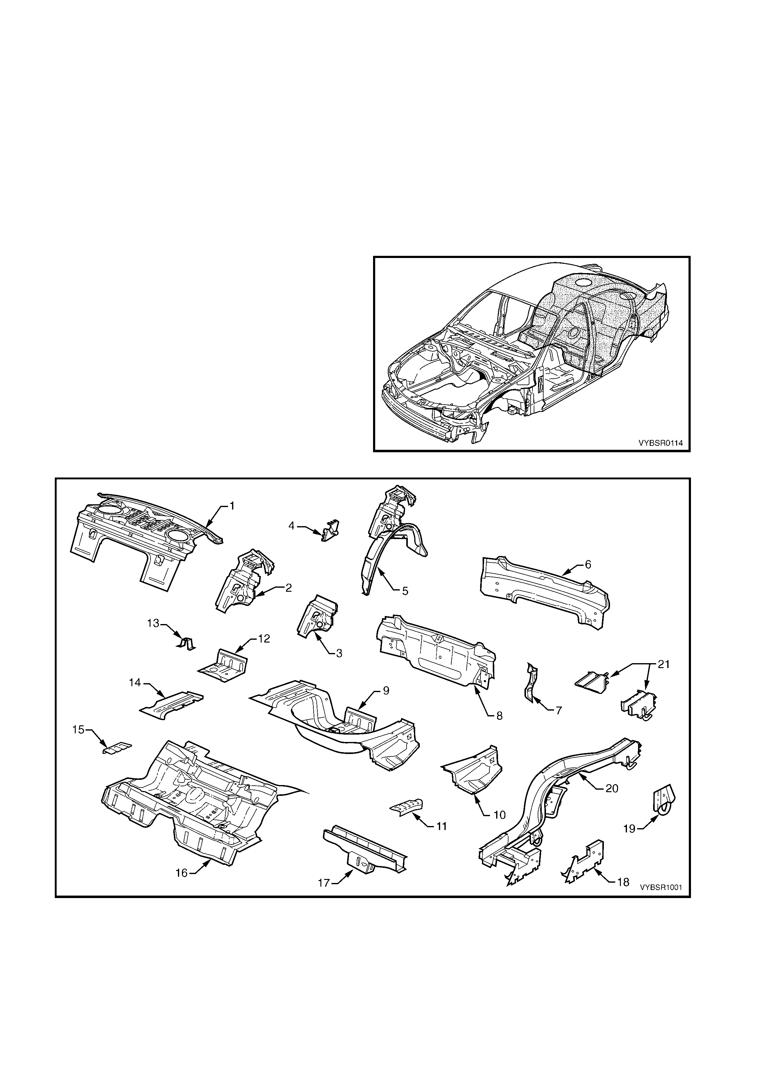
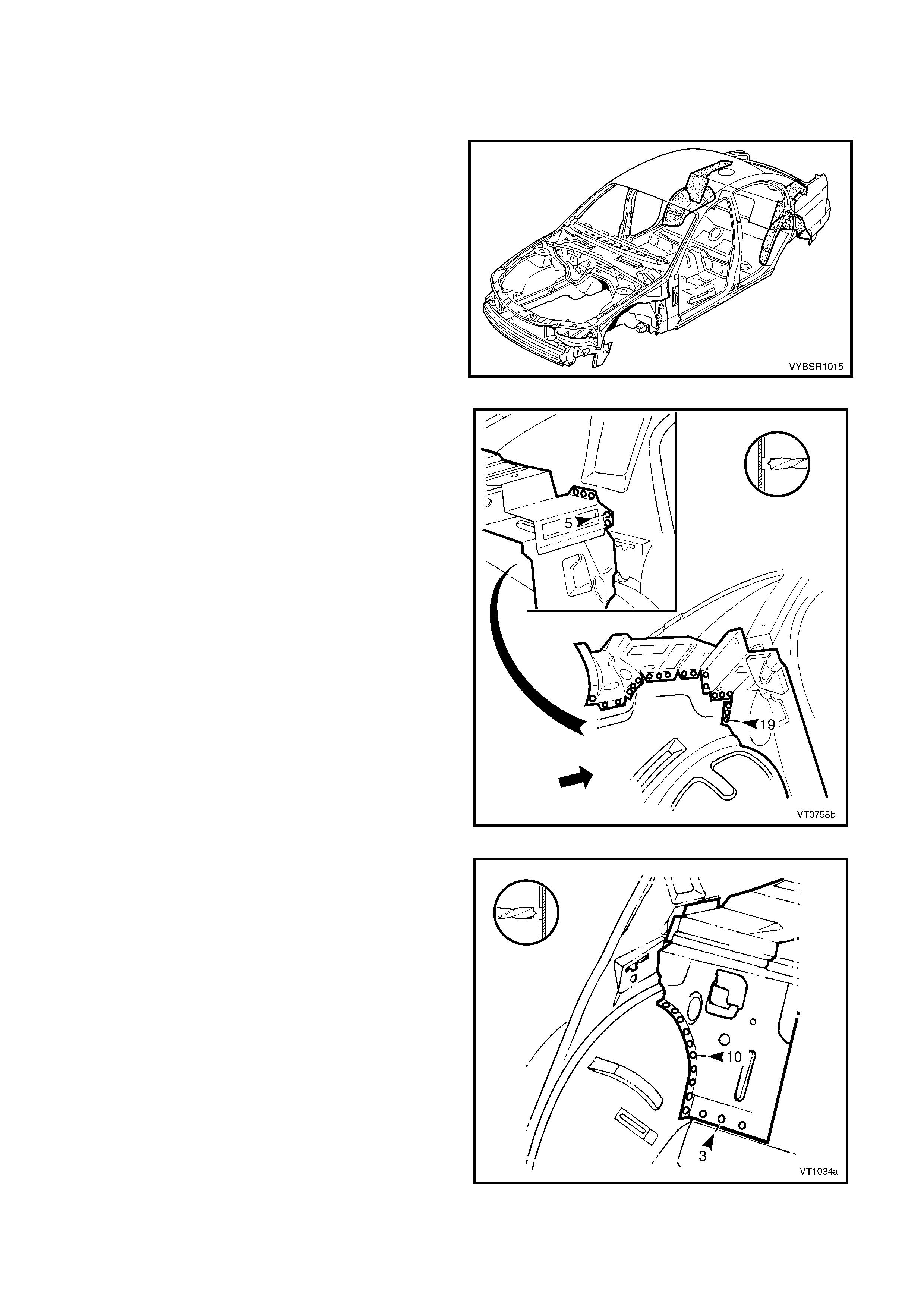
1.1 BODY REAR COMPONENTS
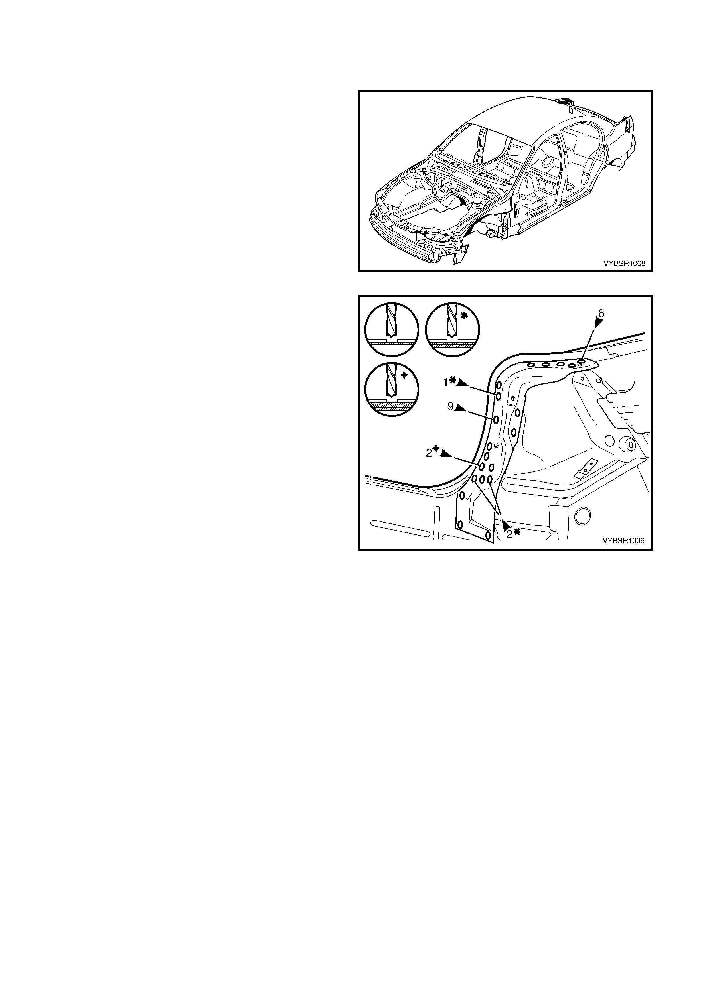
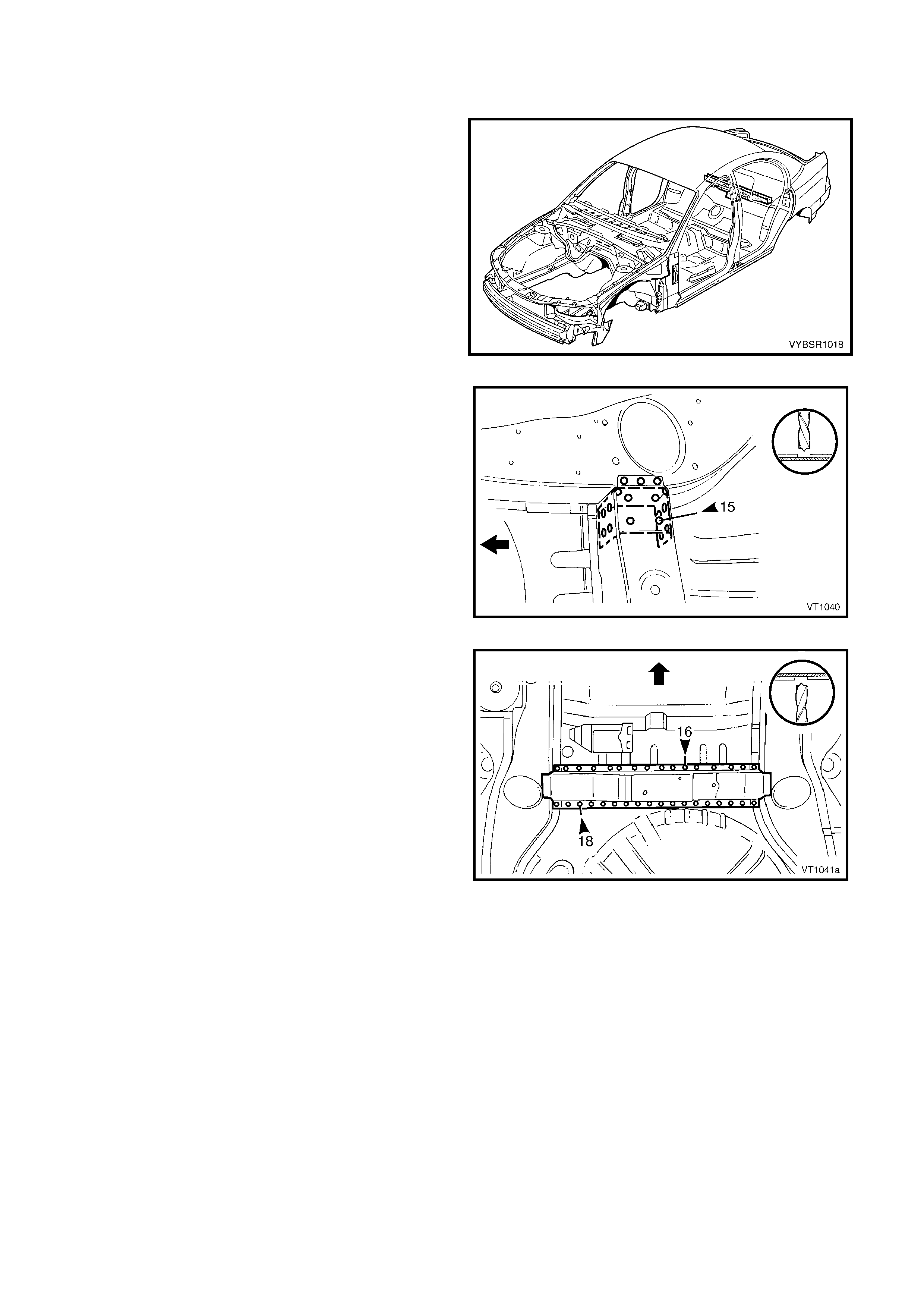
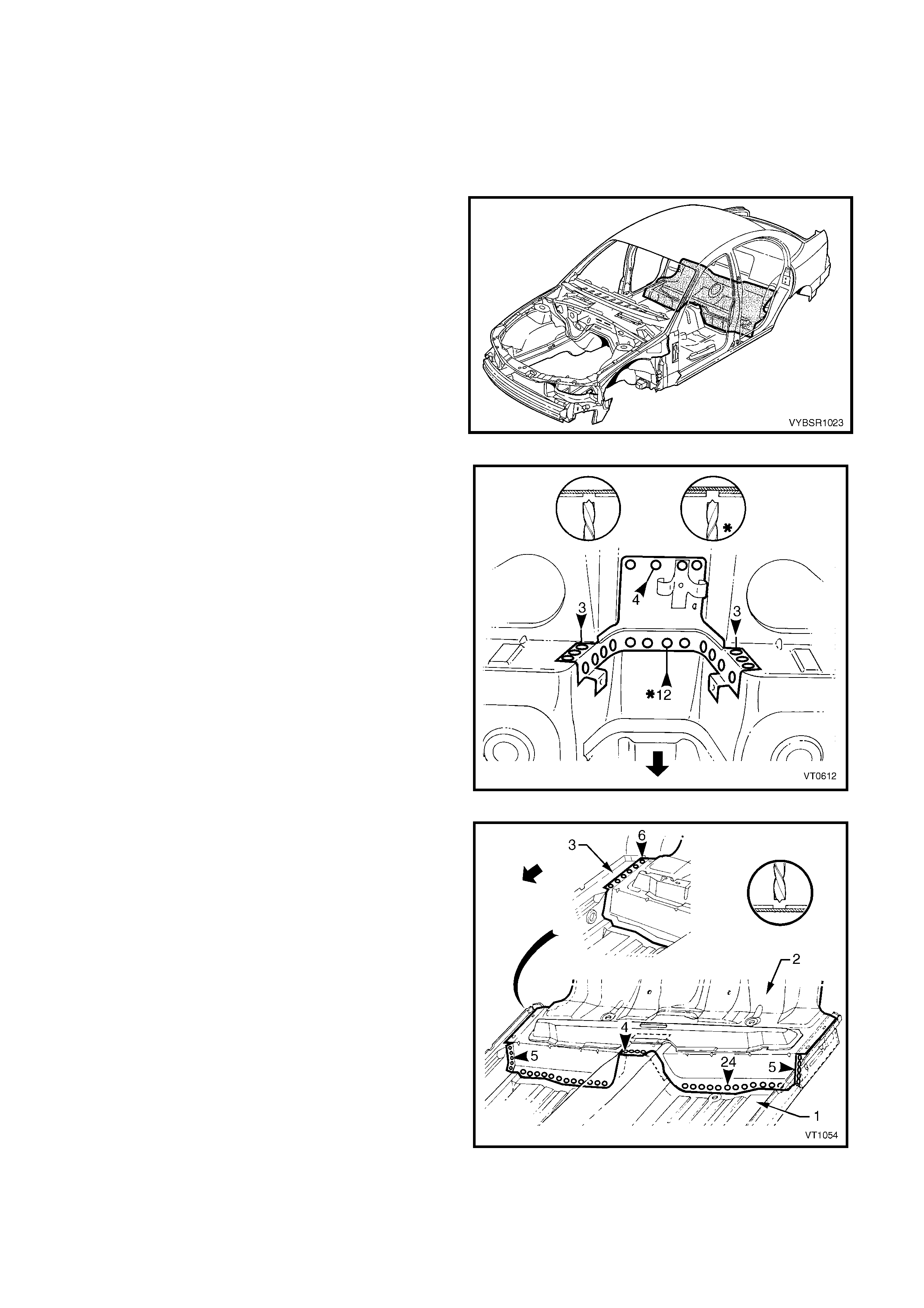
The shaded components in Figure 10A-1 are those
dealt with in this Section.
The components and assemblies shown in Figure
10A-2 are the parts serviced for MY 2003 VY Series
Sedan vehicles which form the basis of the repair
procedures in this Section. For a detailed view of the
body components, refer to Section 3A BODY
CONSTRUCTION – SEDAN.
NOTE: Always refer to your Authorised Retailer for
spare parts availability configurations.
Figure 10A-1
Figure 10A-2

Legend
1. Rear Window Panel Assembly
2. Rear Seat Back Panel Extension Assembly
3. Rear Seat Back Panel Extension
4. Rear Compartment Lid Strut Bracket Assembly
5. Rear Wheelhouse Panel Assembly
6. Rear End Lower Panel
7. Rear End Panel Extension
8. Rear End Panel Assembly
9. Rear Compartment Floor Panel Assembly
10. Rear Compartment Floor Panel Outer Extension,
Left-Hand
11. Rear Floor Panel Reinforcement, Left-Hand
12. Fuel Tank Support Reinforcement Assembly
13. Spare Wheel Anchor Plate Assembly
14. Rear Compartment Floor Panel Outer Extension,
Right-Hand
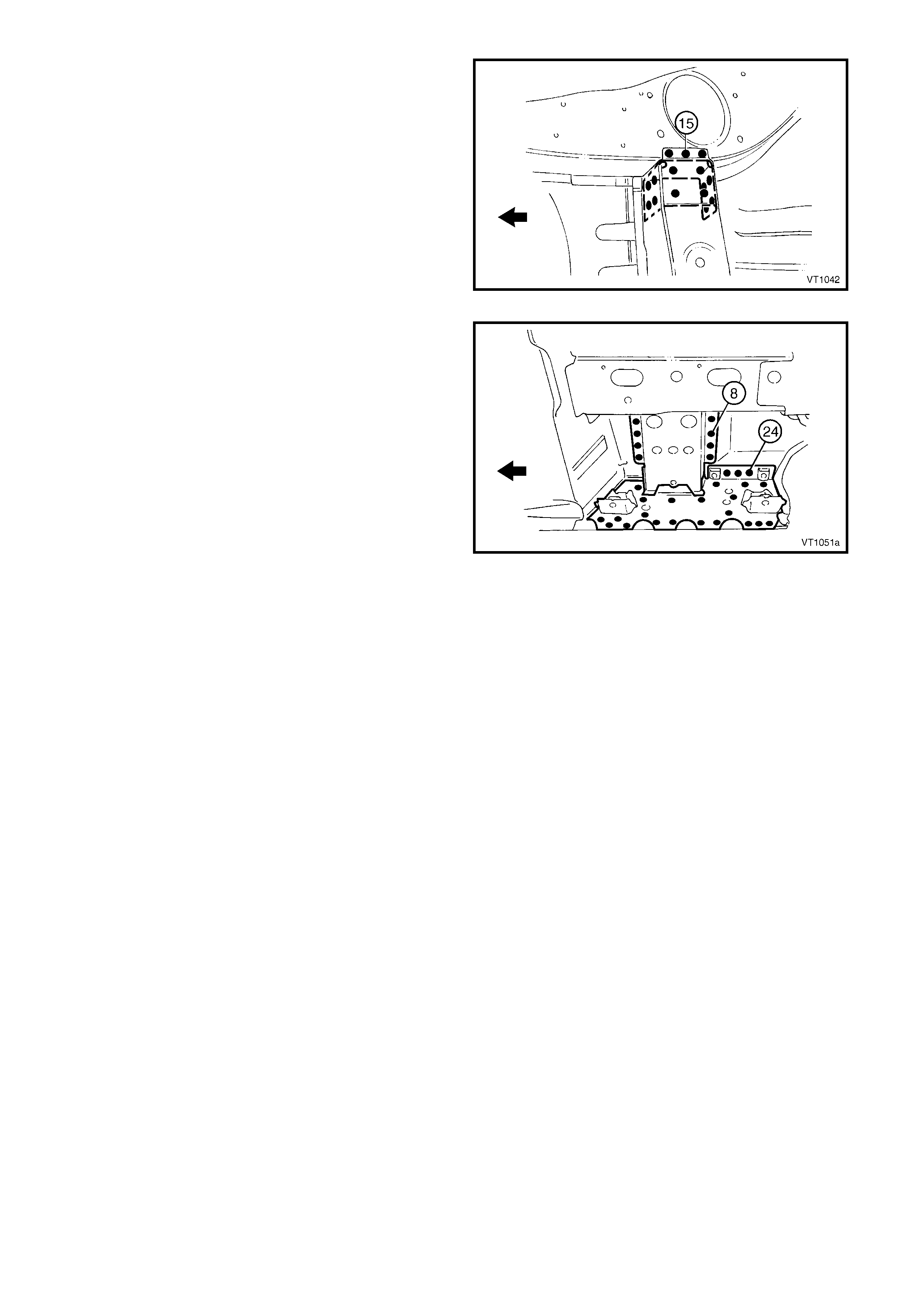
15. Rear Floor Panel Reinforcement, Right-Hand
16. Rear Floor Panel Assembly
17. Crossmember Assembly No. 2
18. Rear Floor Panel Outer Extension
19. Rear Tie Down Assembly
20. Rear Side Rail Assembly
21. Rear Bumper Impact Bar Brace Assembly
NOTE 1: Rear wheelhouse panel assembly includes part 2, which includes parts 3 & 4.
NOTE 2: Rear compartment floor panel assembly includes parts No. 10, 12, 13 & 14.
NOTE 3: Rear side rail assembly includes parts No. 18, 19 & 21.
2. SERVICE OPERATIONS
2.1 REAR END LOWER PANEL – REPLACE
NOTE: If the rear end panel (inner) is also to be
replaced, remove the rear end panels as an
assembly. Refer to 2.2 REAR END PANEL –
REPLACE.
REMOVE
CAUTION: To avoid the possibility of fire, take
particular care when cu tt ing or welding at the rear
of the vehicle. Remove the fuel tank and plug all
fuel lines.
1. Remove the adjacent bolt-on panels and
components as described in the appropriate
Section of the MY 2003 VY & V2 Series II Service
Information.
2. Remove the rear bumper impact bar assembly,
refer to Section 3, 2. BUMPER IMPACT BAR
ASSEMBLIES.
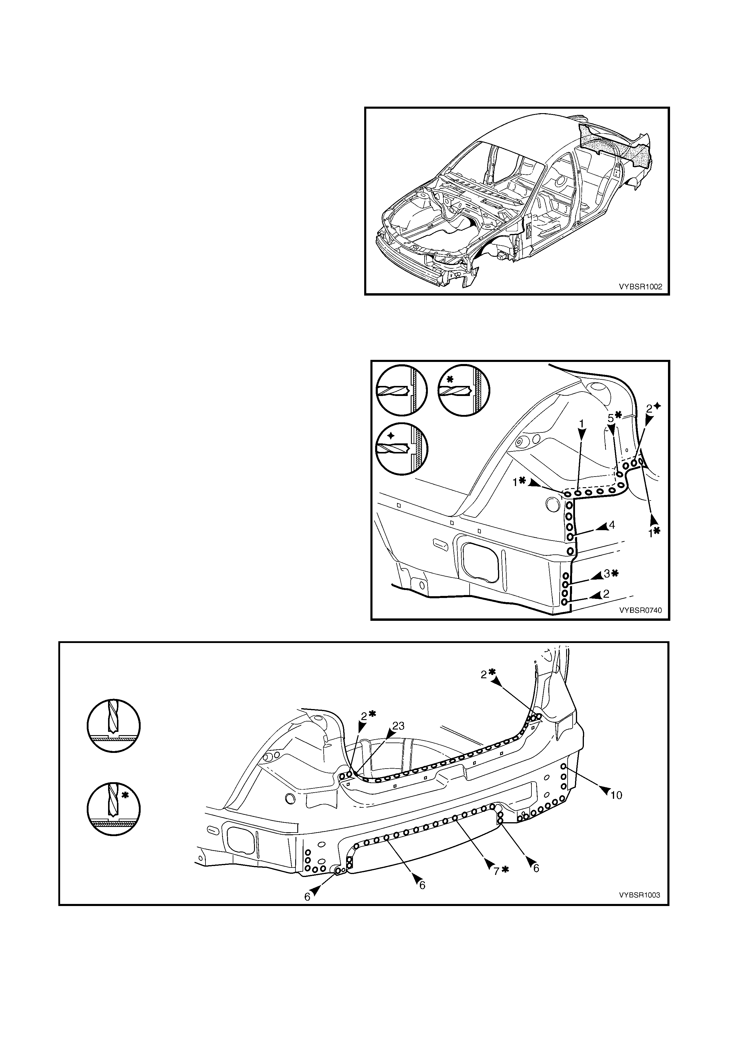
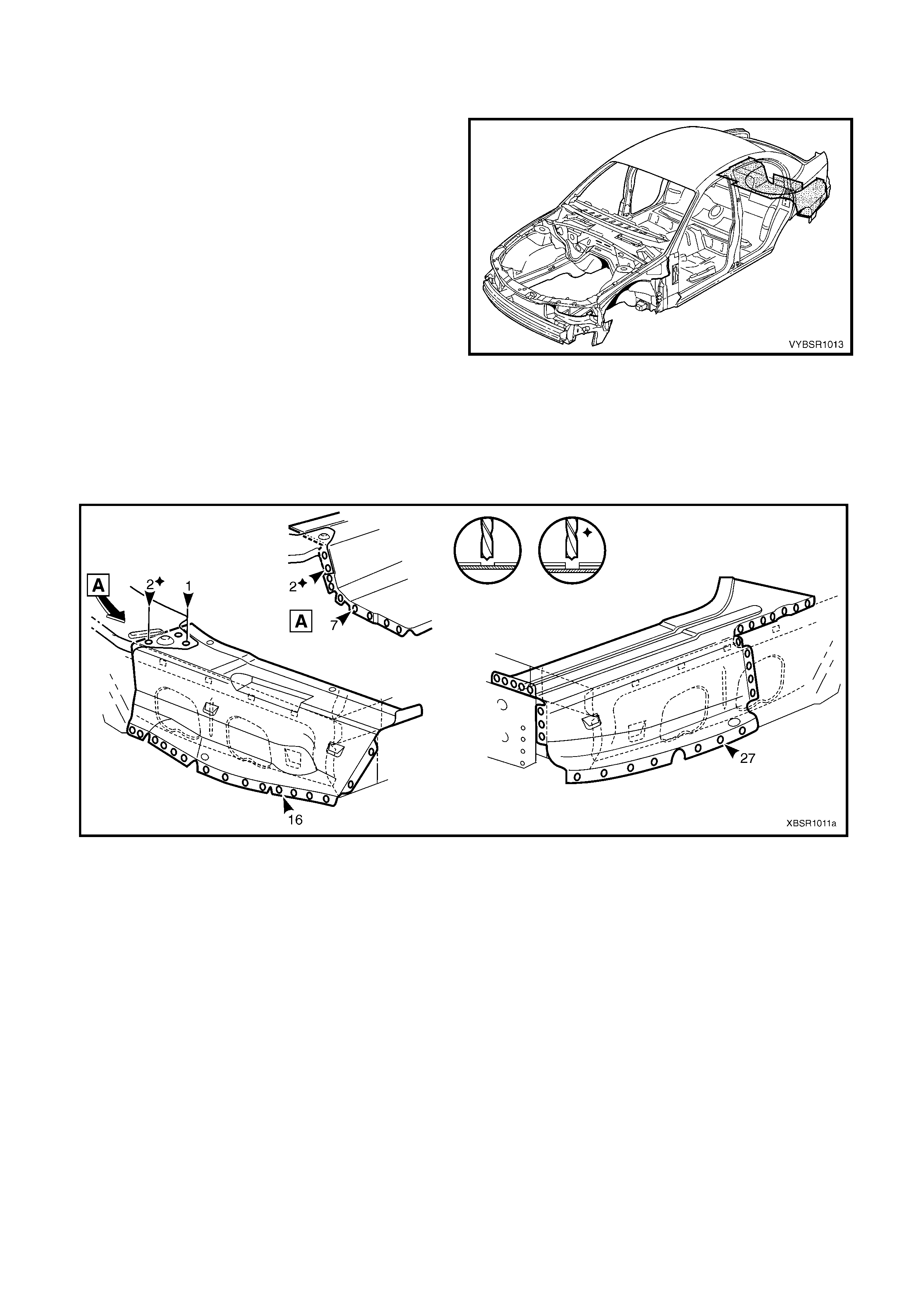
Figure 10A-3
3. Spot cut the welds attaching the rear end lower
panel to the rear quarter panel, web plate, quarter
panel lower extension panel and tail lamp housing.
4. Spot cut the welds attaching the rear end lower
panel to the rear end panel ass em bly and rear end
panel extension, refer to Figure 10A-5.
Figure 10A-4
Figure 10A-5
5. Remove the rear end lower panel from the vehicle and repair any damage to adjacent parts as required.
NOTE: Carefully bend the flange of the rear quarter panel and quarter panel lower extension to allow removal of
the rear end lower panel.
REPLACE
NOTE 1: Spot welding is the preferred method for attaching of panels and should be used whenever possible.
Where the spot welding equipment available will not access the required weld position, a plug weld should be
performed.
NOTE 2: The same number and position of spot welds ( or plug welds) should be used when replacing the panel,
as was used during manufacture, in order to maintain the original structural strength of the vehicle.
1. As required, mark the new panel with drilling locations in preparation for plug welding. Drill holes as required.
2. Prepare all mating surfaces and treat with Weld Through Primer (Item 1) as required, refer to
5. BODY SEALING, ADHESIVES & DEADENERS in Section 3A.
3. Clamp the rear end lower panel in position on the vehicle ensuring it is seated under the rear quarter panel
and quarter panel lower extension flanges.
4. Spot cut the welds attaching the rear end lower panel to the rear end panel assembly and rear end panel
extension, refer to Figure 10A-6.
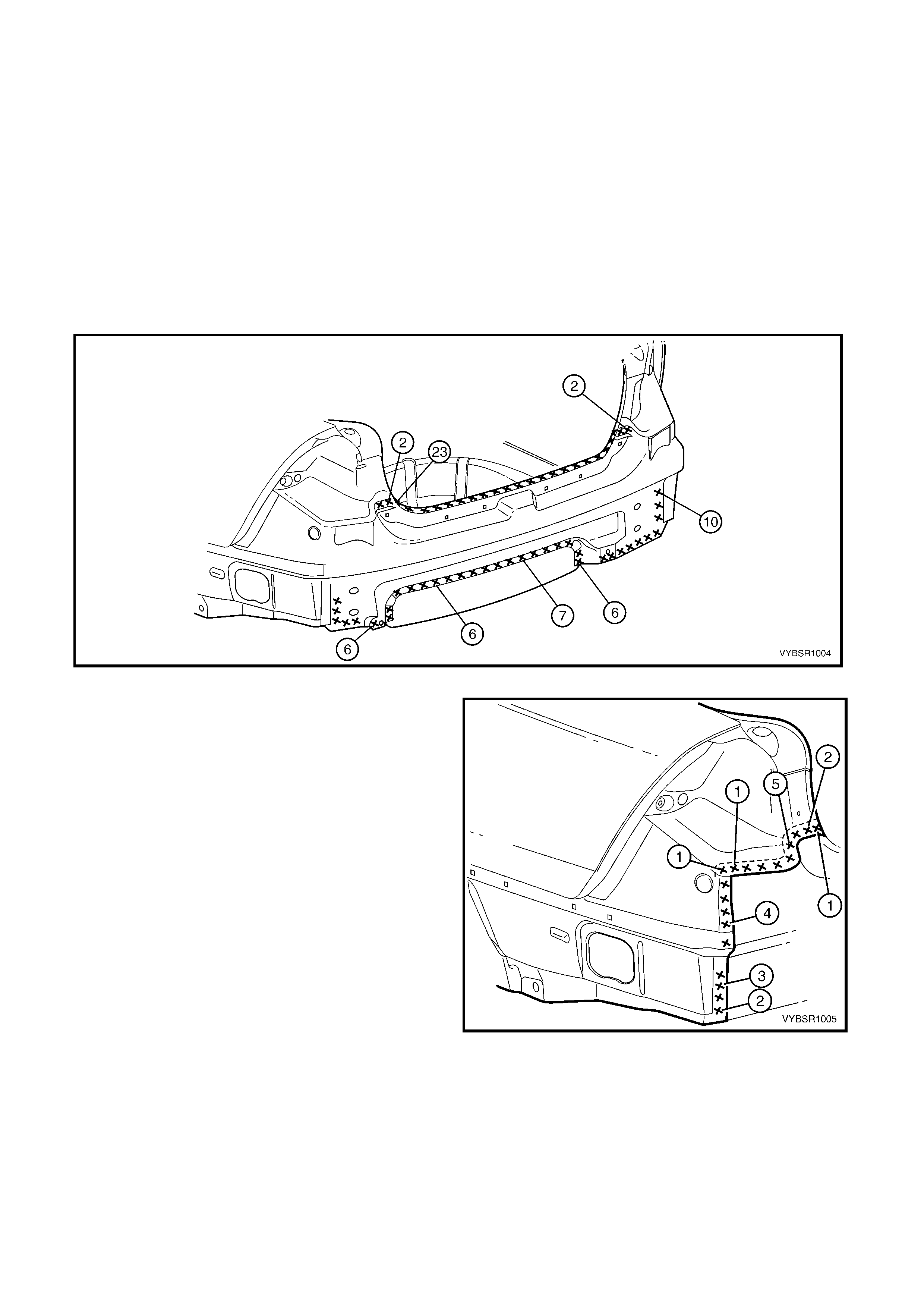
Figure 10A-6
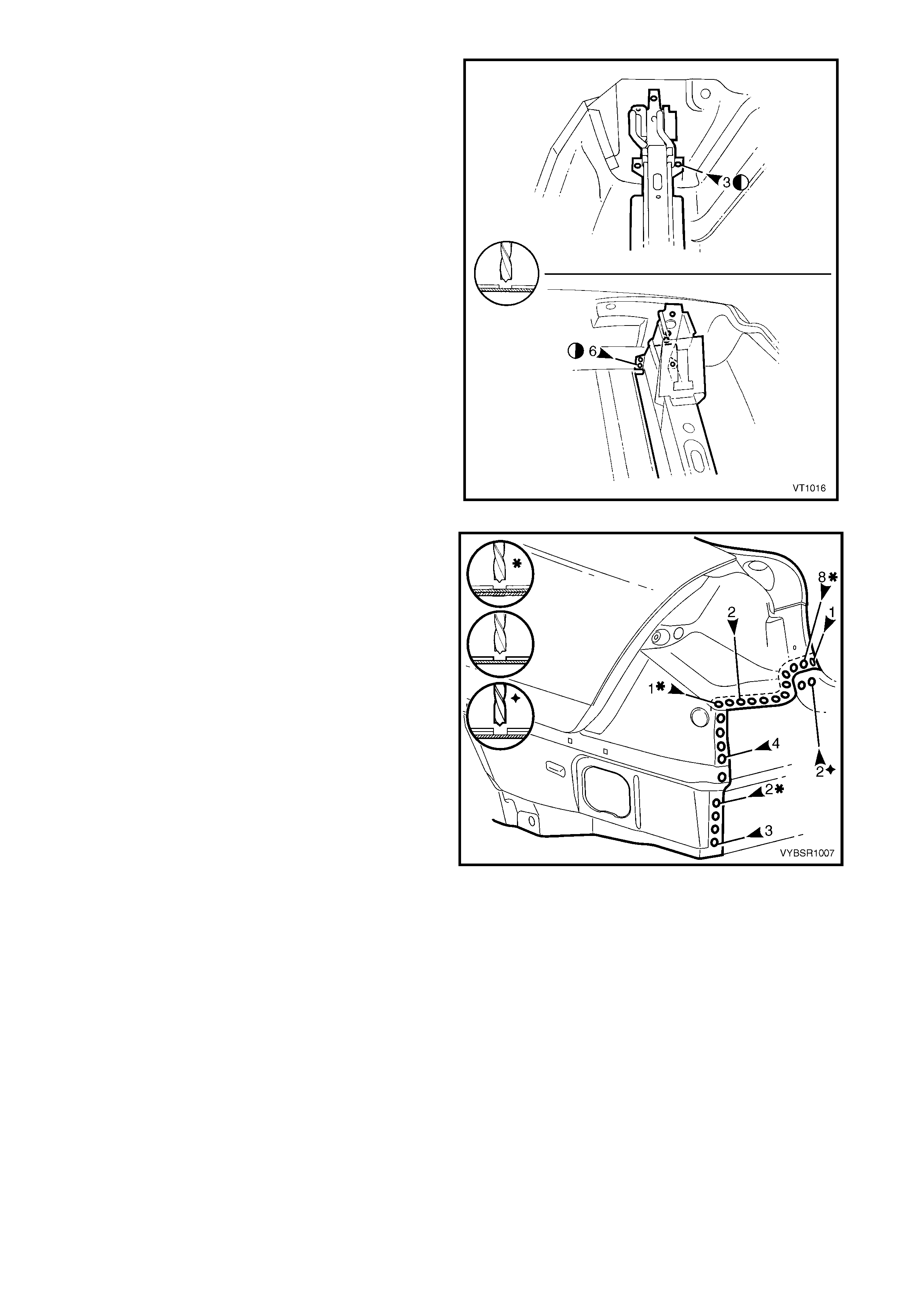
5. Spot or plug weld the rear end lower panel to the
rear quarter panel, web plate, quarter panel lower
extension panel and tail lamp housing.
6. Refinish and paint panels and other components
as required. Refer to Section 3, 1.3 PAINT
REFINISHING.
7. Apply Joint Sealer (Item 3) as required. Refer to
5. BODY SEALING, ADHESIVES & DEADENERS
in Section 3A.
8. Apply Cavity Wax (Item 8) as r equired to the inside
of any box sections or areas inaccessible to paint,
refer to 6. CAVITY WAX in Section 3A.
9. Install the rear bumper impact bar assembly, refer
to Section 3, 2. BUMPER IMPACT BAR
ASSEMBLIES.
10. Install the remaining components as described in
the appropriate Section of the MY 2003 VY & V2
Series II Service Information.
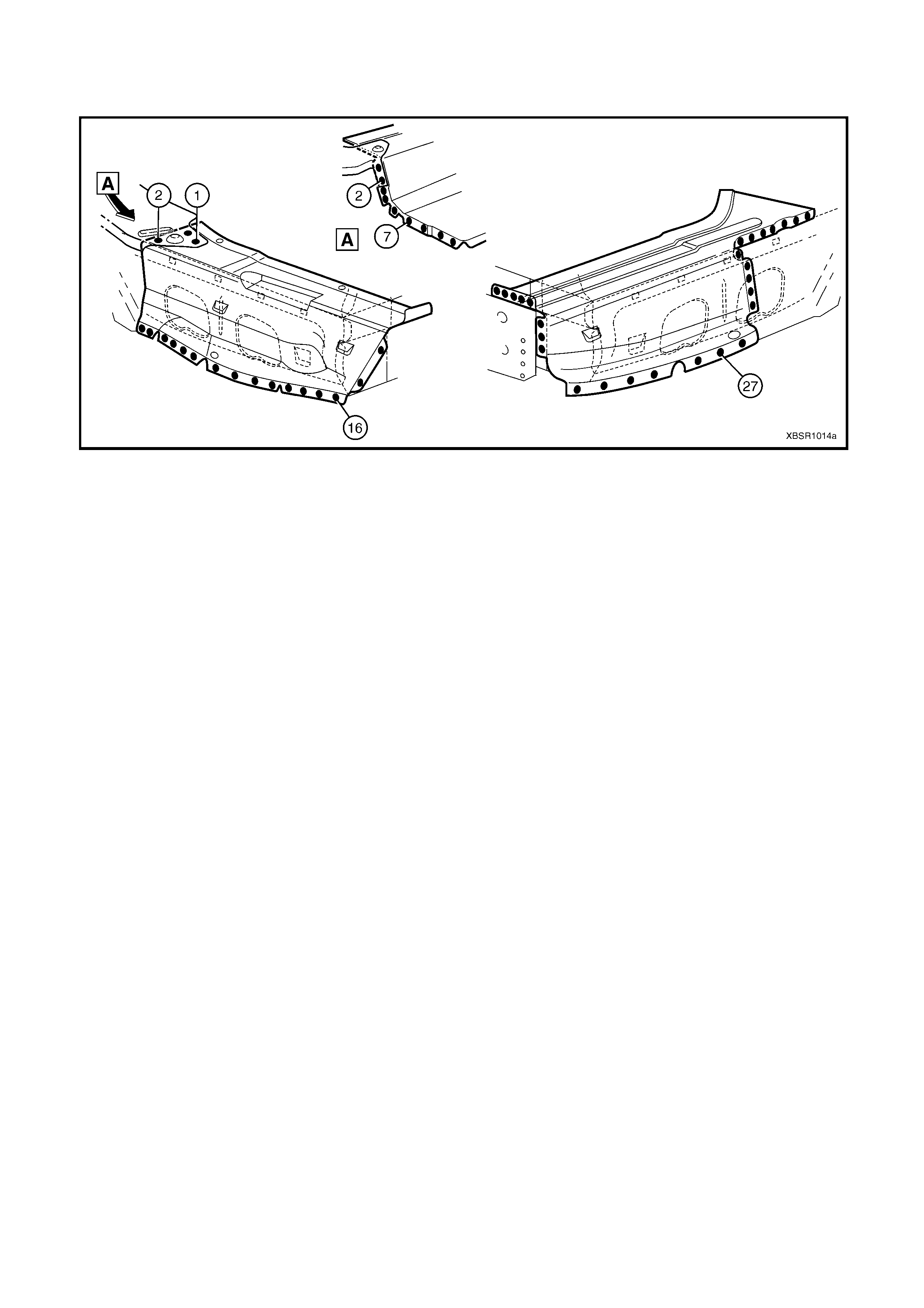
Figure 10A-7
2.2 REAR END PANEL ASSEMBLY – REPLACE
NOTE: This procedure describes the removal of the
rear end lower panel and rear end panel as an
assembly. As the panels are supplied individually, this
procedure contains the replacement of the rear end
panel only. Reference should be then made to
2.1 REAR END LOWER PANEL – REPLACE for the
relevant replacement procedures of the remaining
panel.
REMOVE
CAUTION: To avoid the possibility of fire, take
particular care when cutting or welding at the rear
of the vehicle. Remove the fuel tank and plug all
fuel lines.
1. Remove the adjacent bolt-on panels and
components as described in the appropriate
Section of the MY 2003 VY & V2 Series II Service
Information.
2. Remove the rear bumper impact bar assembly,
refer to 2. BUMPER IM PACT BAR ASSEMBLIES
in Section 3.
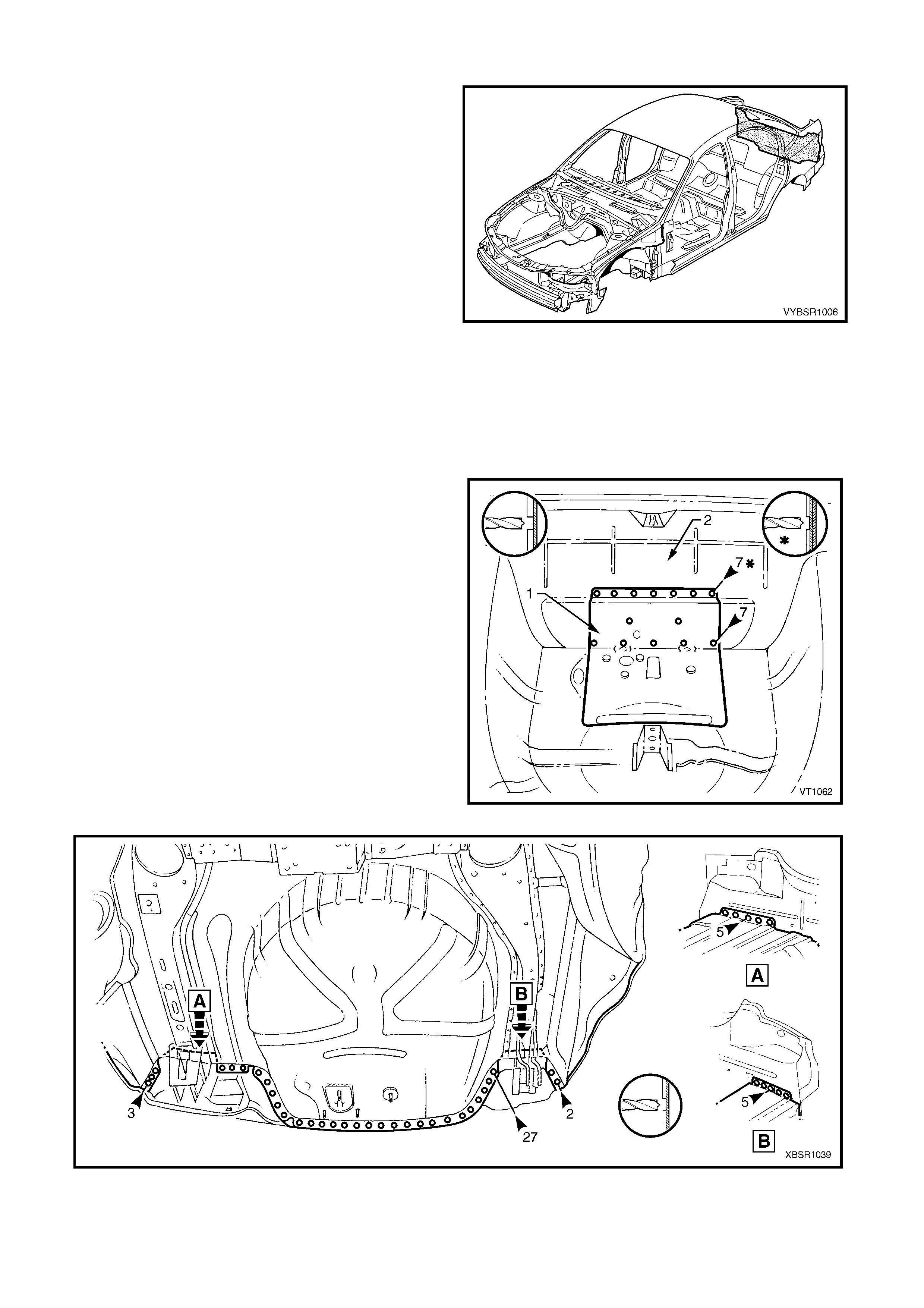
Figure 10A-8
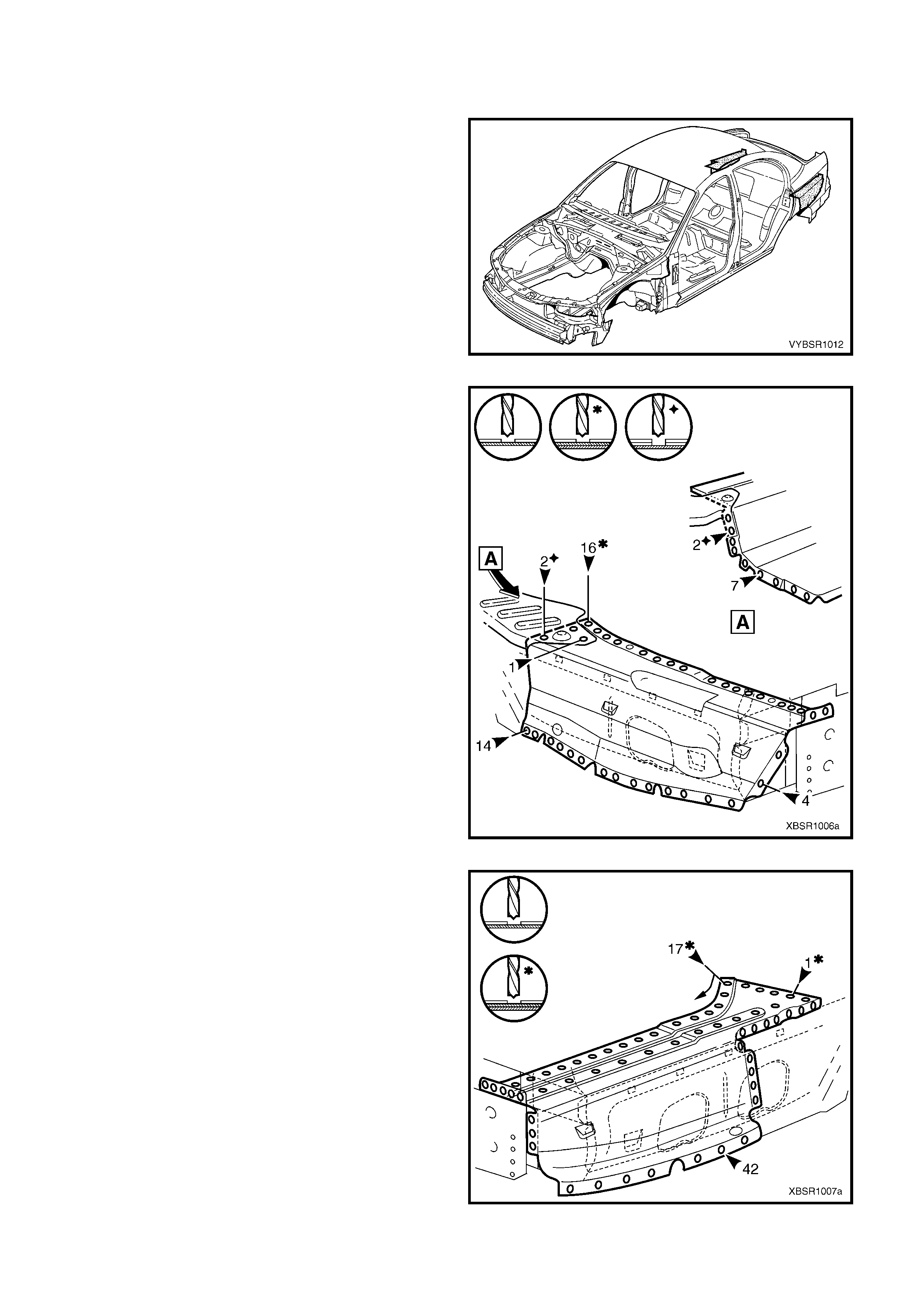
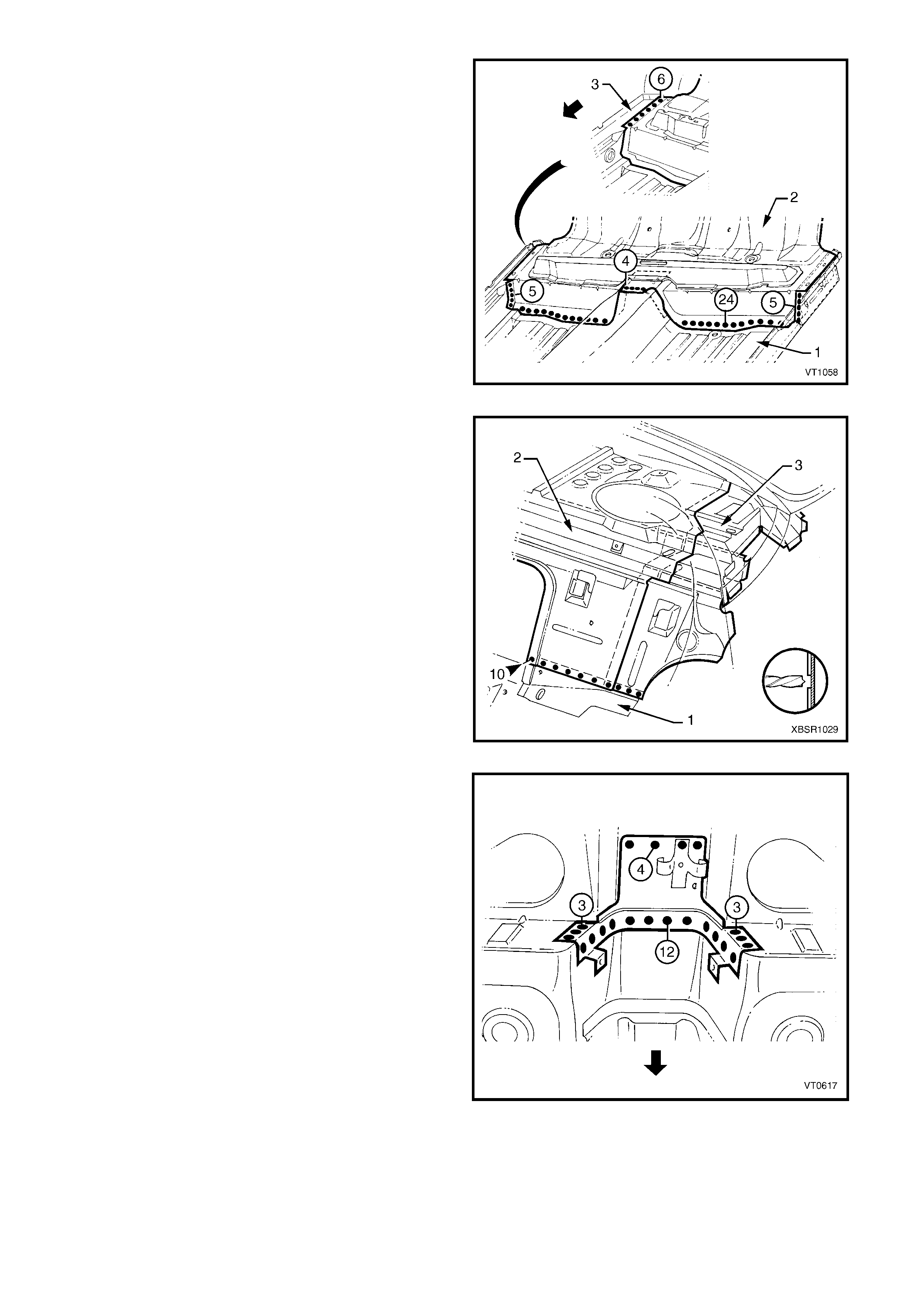
3. Spot cut the welds attaching the fuel tank support
reinforcement (1) to the rear end panel assembly
(2).
NOTE: As an alternative, r emove the f uel tank suppor t
reinforcement from the rear compartment floor panel
assembly, refer to 2.4 FUEL TANK SUPPORT
REINFORCEMENT ASSEMBLY – REPLACE.
4. Spot cut the welds attaching the rear end panel
assem bly to the rear com partment floor assem bly,
refer to Figure 10A-10.
Figure 10A-9
Figure 10A-10
5. Spot cut the welds attaching the rear side rail
assem blies to the rear end panel assem bly. Note
that the left-hand side is different to the right-
hand side.
Figure 10A-11
6. Spot cut the welds attaching the rear end panel
assembly to the rear quarter panel, rear quarter
panel lower extens ion, tail lamp housing and rear
end panel extension as required on each side of
the vehicle.
7. Remove the panels from the vehicle then repair
any damage to adjacent parts as required.
NOTE: Carefully bend the flange of the rear quarter
panel, and quarter panel lower extension to allow
removal of the rear end panel assembly.
8. Check and rectify the alignment of the body as
required, refer to 3. BODY DIMENSIONS in
Section 3A.
Figure 10A-12
REPLACE
NOTE 1: Spot welding is the preferred method for attaching of panels and should be used whenever possible.
Where the spot welding equipment available will not access the required weld position, a plug weld should be
performed.
NOTE 2: The same number and position of spot welds ( or plug welds) should be used when replacing the panel,
as was used during manufacture, in order to maintain the original structural strength of the vehicle.
1. As required, mark the new panel with drilling locations in preparation for plug welding. Drill holes as required.
2. Prepare all mating surfaces and treat with Weld Through Primer (Item 1) as required, refer to
5. BODY SEALING, ADHESIVES & DEADENERS in Section 3A.
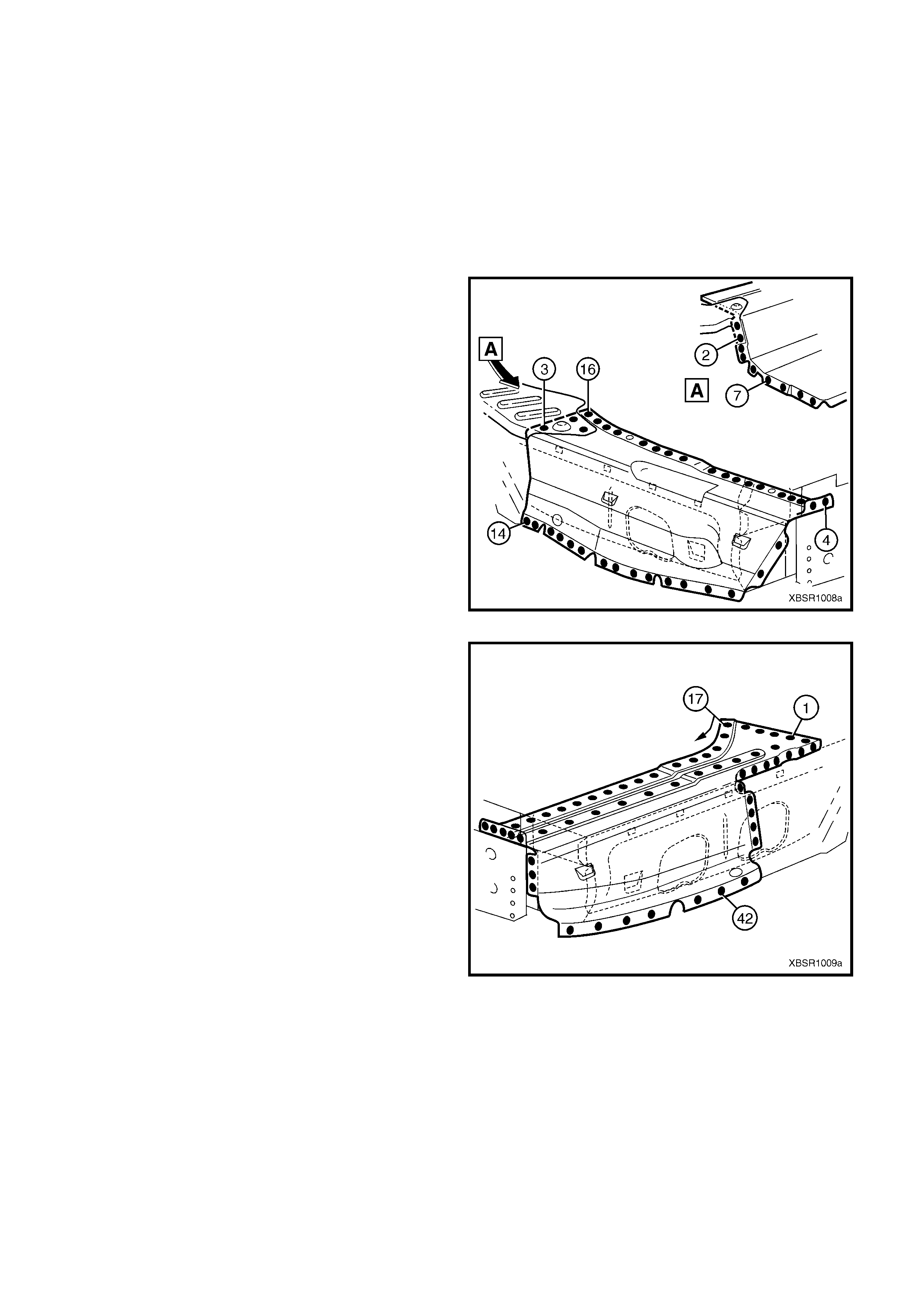
3. Clamp the rear end panel in position on the vehic le
and spot or plug weld to the rear compartment
floor panel assembly.
NOTE: If the r ear quar ter panel, tail lamp hous ing, rear
end panel extension and rear quarter panel extension
were not removed, ensure the rear end panel is
positioned behind the flange of these panels.
Figure 10A-13
4. Spot or plug weld the rear end panel to the rear
side rail ass em bly on each side of the vehicle. T he
left-hand side is different to the right-hand side.
5. If removed, install the fuel tank support
reinforcement and weld to the rear compartment
floor panel assembly ONLY, refer to
2.4 FUEL T ANK SUPPORT REINFORCEM ENT –
REPLACE.
6. In the areas where the rear end lower panel will fit,
grind the welds and prime any bare metal.
7. Install the rear end lower panel, refer to
2.1 REAR END LOWER PANEL – REPLACE.
Figure 10A-14
8. Finish plug welding the fuel tank support
reinforcement to the rear end panel.
9. Refinish and paint panels and other components
as required. Refer to Section 3, 1.3 PAINT
REFINISHING.
10. Apply Joint Sealer (Item 3) as required. Refer to
5. BODY SEALING, ADHESIVES & DEADENERS
in Section 3A.
11. Apply Cavity Wax (Item 8) as r equired to the inside
of any box sections or areas inaccessible to paint,
refer to 6. CAVITY WAX in Section 3A.
12. Install the rear bum per impact bar assembly, refer
to 2. BUMPER IMPACT BAR ASSEMBLIES in
Section 3.
13. Install the remaining components as described in
the appropriate Section of the MY 2003 VY & V2
Series II Service Information.
Figure 10A-15
2.3 REAR END PANEL EXTENSION – REPLACE
REMOVE
1. Remove the adjacent bolt-on panels and
components as described in the appropriate
Section of the MY 2003 VY & V2 Series II Service
Information.
2. Remove surrounding panels as required, refer to
the appropriate procedure in this supplement.
Figure 10A-16
3. As required, spot cut the welds attaching the rear
end panel extension to the rear end panel, tail
lamp housing and quarter panel upper extension.
4. Remove the rear end panel extension from the
vehicle and then repair any damage to adjacent
parts as required.
Figure 10A-17
REPLACE
NOTE 1: Spot welding is the preferred method for attaching of panels and should be used whenever possible.
Where the spot welding equipment available will not access the required weld position, a plug weld should be
performed.
NOTE 2: The s am e num ber and pos ition of s pot welds (or plug welds) s hould be used when replac ing the panel, as
was used during manufacture, in order to maintain the original structural strength of the vehicle.
1. As required, mark the new panel with drilling locations in preparation for plug welding. Drill holes as required.
2. Prepare all mating surfaces and treat with Weld Through Primer (Item 1) as required, refer to
5. BODY SEALING, ADHESIVES & DEADENERS in Section 3A.
3. As required, spot or plug weld the rear end panel
extension to the surrounding panels.
4. Refinish and paint panels and other components
as required. Refer to Section 3, 1.3 PAINT
REFINISHING.
5. Apply Joint Sealer (Item 3) as required. Refer to
5. BODY SEALING, ADHESIVES & DEADENERS
in Section 3A.
6. Apply Cavity Wax ( Item 8) as requir ed to the inside
of any box sections or areas inaccessible to paint,
refer to 6. CAVITY WAX in Section 3A.
7. Install the remaining components as described in
the appropriate Section of the MY 2003 VY & V2
Series II Service Information.
Figure 10A-18
2.4 FUEL TANK SUPPORT REINFORCEMENT ASSEMBLY – REPLACE
REMOVE
CAUTION: To avoid the possibility of fire, take
particular care when cutting or welding at the rear
of the vehicle. Remove the fuel tank and plug all
fuel lines.
1. Remove the adjacent bolt-on panels and
components as described in the appropriate
Section of the MY 2003 VY & V2 Series II Service
Information.
2. Remove the deadener panels and j oint s ealer from
around the fuel tank support reinforcement
assembly as required.
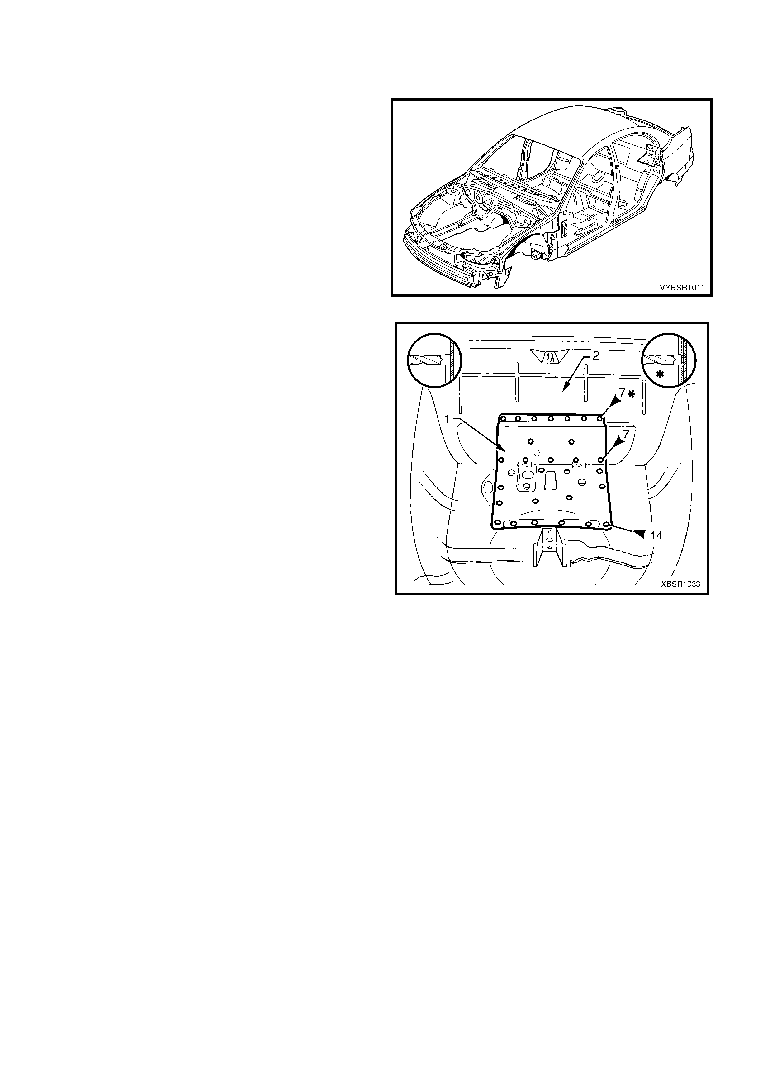
Figure 10A-19
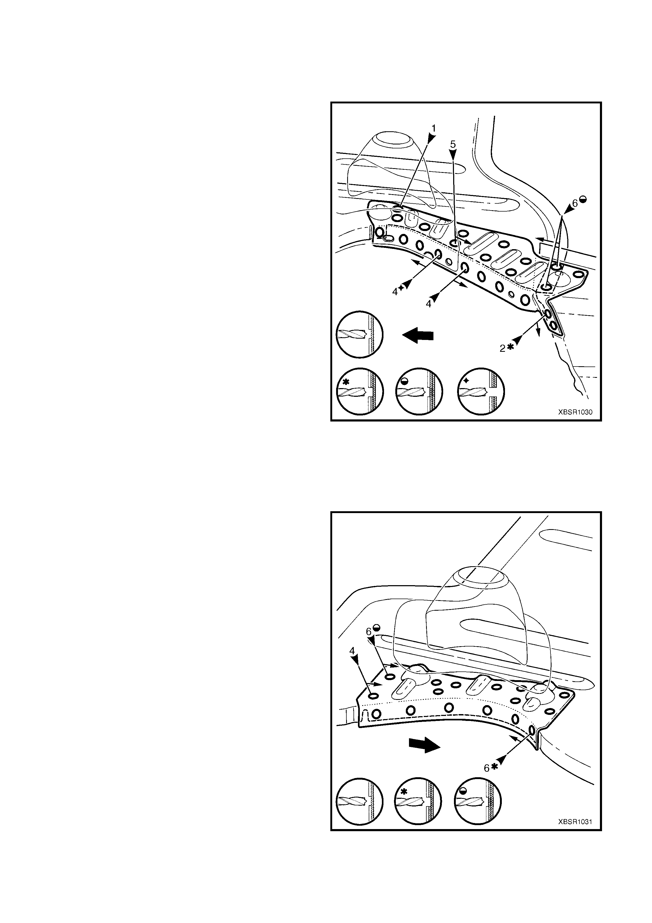
3. Spot cut the 14 welds attaching the reinforcement
to the rear end panel assembly.
4. Spot cut the 14 welds attaching the reinforcement
to the rear compartment floor panel assembly.
5. Remove the fuel tank support reinforcement
assem bly and then repair any damage to adjacent
parts as required.
Figure 10A-20
REPLACE
NOTE 1: Spot welding is the preferred method for attaching of panels and should be used whenever possible.
Where the spot welding equipment available will not access the required weld position, a plug weld should be
performed.
NOTE 2: The s am e num ber and pos ition of s pot welds (or plug welds) s hould be used when replac ing the panel, as
was used during manufacture, in order to maintain the original structural strength of the vehicle.
1. As required, mark the new panel with drilling locations in preparation for plug welding. Drill holes as required.
2. Prepare all mating surfaces and treat with Weld Through Primer (Item 1) as required, refer to
5. BODY SEALING, ADHESIVES & DEADENERS in Section 3A.
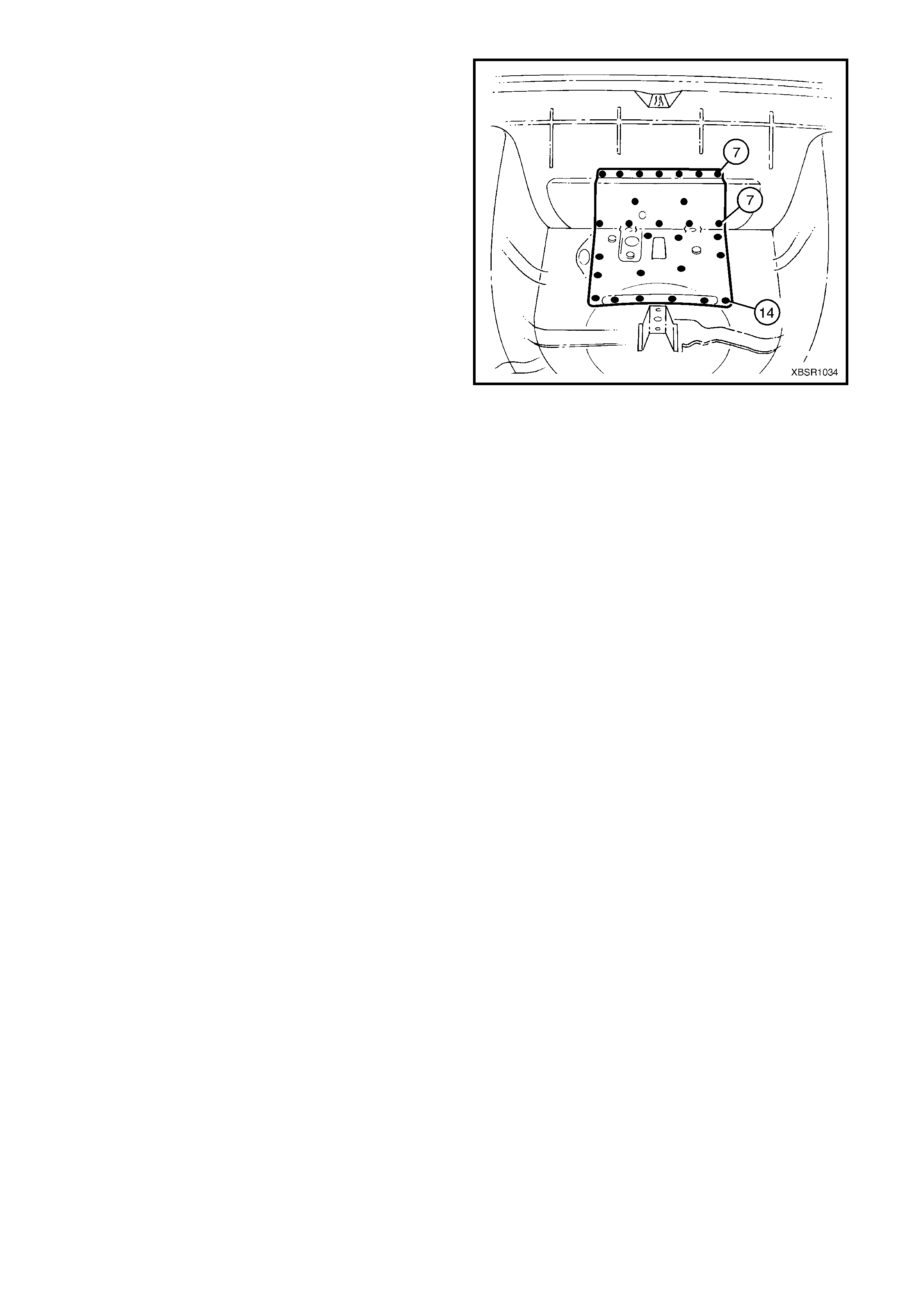
3. Plug weld the fuel tank support reinforcement
assembly to the rear compartment floor panel
assembly and rear end panel assembly.
4. Refinish and paint panels and other components
as required. Refer to Section 3, 1.3 PAINT
REFINISHING.
5. Apply Joint Sealer (Item 3) as required. Refer to
5. BODY SEALING, ADHESIVES & DEAD ENERS
in Section 3A.
6. Apply Cavity Wax ( Item 8) as requir ed to the inside
of any box sections or areas inaccessible to paint,
refer to 6. CAVITY WAX in Section 3A.
7. Install the deadener panels as required, refer to
5.6 DEADENER PANELS & INSULATORS in
Section 3A.
8. Install the remaining components as described in
the appropriate Section of the MY 2003 VY & V2
Series II Service Information.
Figure 10A-21
2.5 REAR COMPARTMENT FLOOR PANEL OUTER EXTENSION – REPLACE
REMOVE
CAUTION: To avoid the possibility of fire, take
particular care when cutting or welding at the rear
of the vehicle. Remove the fuel tank and plug all
fuel lines.
1. Remove the adjacent bolt-on panels and
components as described in the appropriate
Section of the MY 2003 VY & V2 Series II Service
Information.
2. Remove the joint sealer from around the rear
compartment floor panel outer extension joins as
required.
Figure 10A-22
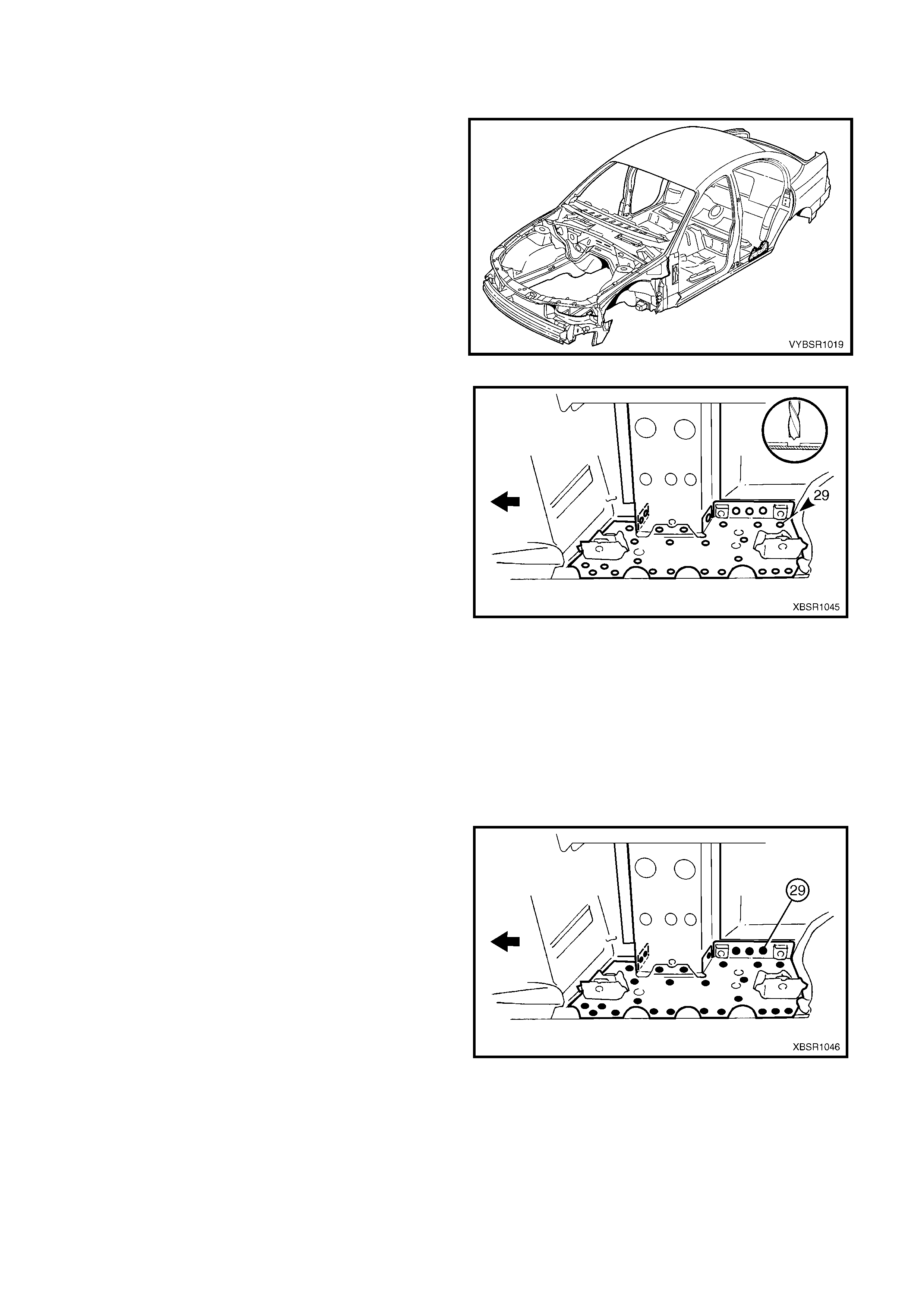
3. Spot cut the welds attaching the rear compar tment
floor panel outer extension to the rear
compartment floor panel, rear side rail assembly,
rear quarter panel and rear wheelhouse panel as
required. Refer to Figure 10A-23 for left-hand or
Figure 10A-24 for right-hand.
NOTE: Also remove several welds from the left-hand
rear floor panel reinforcement as shown.
4. Remove the extension from the vehicle and then
repair any damage to adjacent parts as required.
5. Check and rectify the alignment of the body as
required, refer to 3. BODY DIMENSIONS in
Section 3A.
Figure 10A-23
Figure 10A-24
REPLACE
NOTE 1: Spot welding is the preferred method for attaching of panels and should be used whenever possible.
Where the spot welding equipment will not access the required weld position, a plug weld should be performed.
NOTE 2: The s am e num ber and pos ition of s pot welds (or plug welds) s hould be used when replac ing the panel, as
was used during manufacture, in order to maintain the original structural strength of the vehicle.
1. As required, mark the new panel with drilling locations in preparation for plug welding. Drill holes as required.
2. Prepare all mating surfaces and treat with Weld Through Primer (Item 1) as required, refer to
5. BODY SEALING, ADHESIVES & DEADENERS in Section 3A.
3. Apply Acrylic Spot W eld Sealer (Item 2), refer to 5. BODY SEALING, ADHESIVES & DEADENERS in Section
3A.
4. Fit the left-hand rear compartment floor panel
outer extension in pos ition, ensuring the fr ont edge
is seated under the rear floor panel reinforcement.
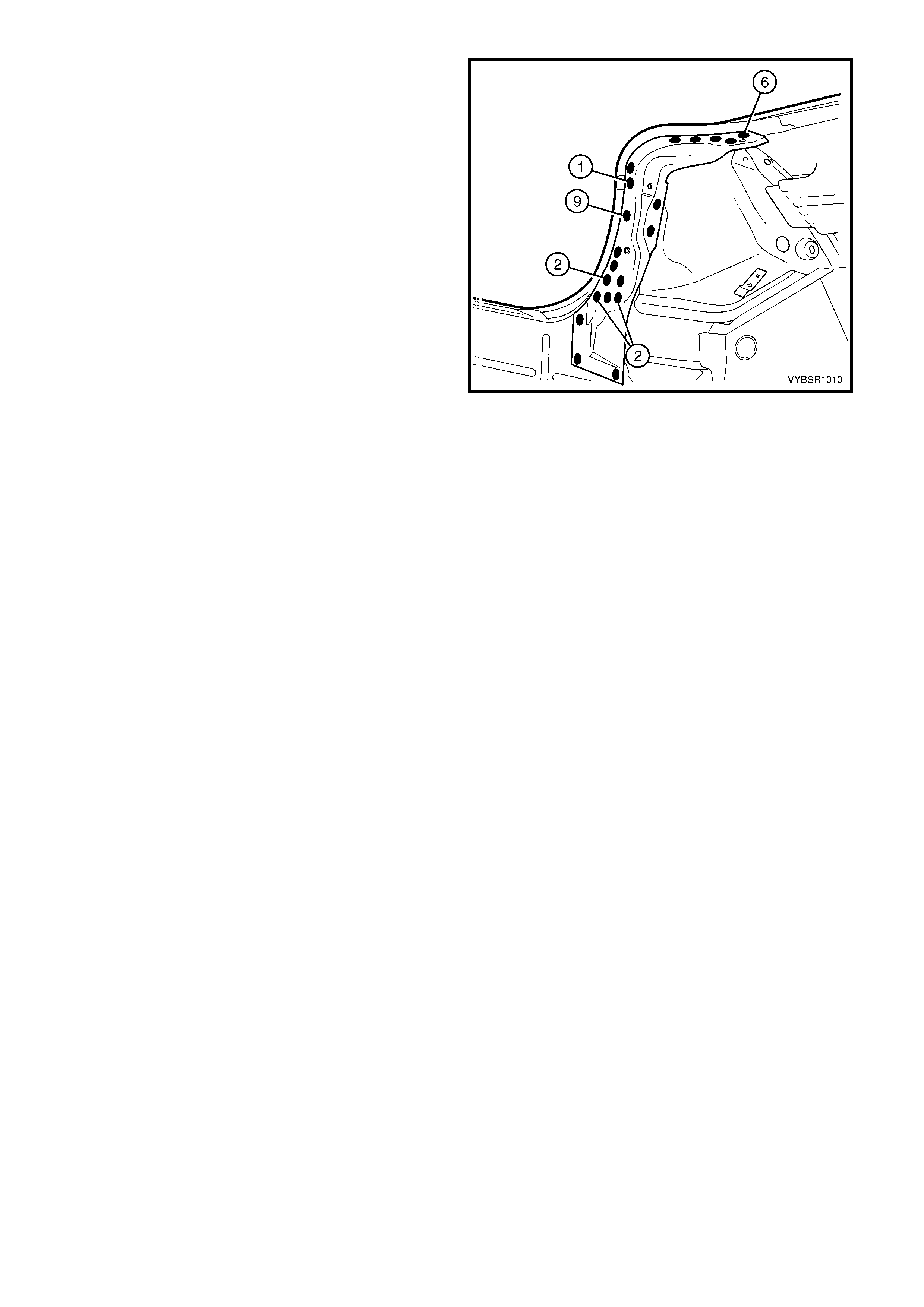
5. Spot or plug weld the extension to the rear
compartment floor panel, rear floor panel
reinfor cement, r ear s ide rail as s embly, rear quarter
panel and the rear wheelhouse panel as required.
Figure 10A-25
6. Fit the right-hand rear compartment floor panel
outer ex tension and s pot or plug weld it to the rear
compartment floor panel, rear side rail assembly,
rear quarter panel and the rear wheelhouse panel
as required.
7. Replac e any other rem oved panels as desc r ibed in
this Supplement.
8. Refinish and paint panels and other components
as required. Refer to Section 3, 1.3 PAINT
REFINISHING.
9. Apply Joint Sealer (Item 3) as required. Refer to
5. BODY SEALING, ADHESIVES & DEADENERS
in Section 3A.
10. Apply Cavity Wax (Item 8) as r equired to the inside
of any box sections or areas inaccessible to paint,
refer to 6. CAVITY WAX in Section 3A.
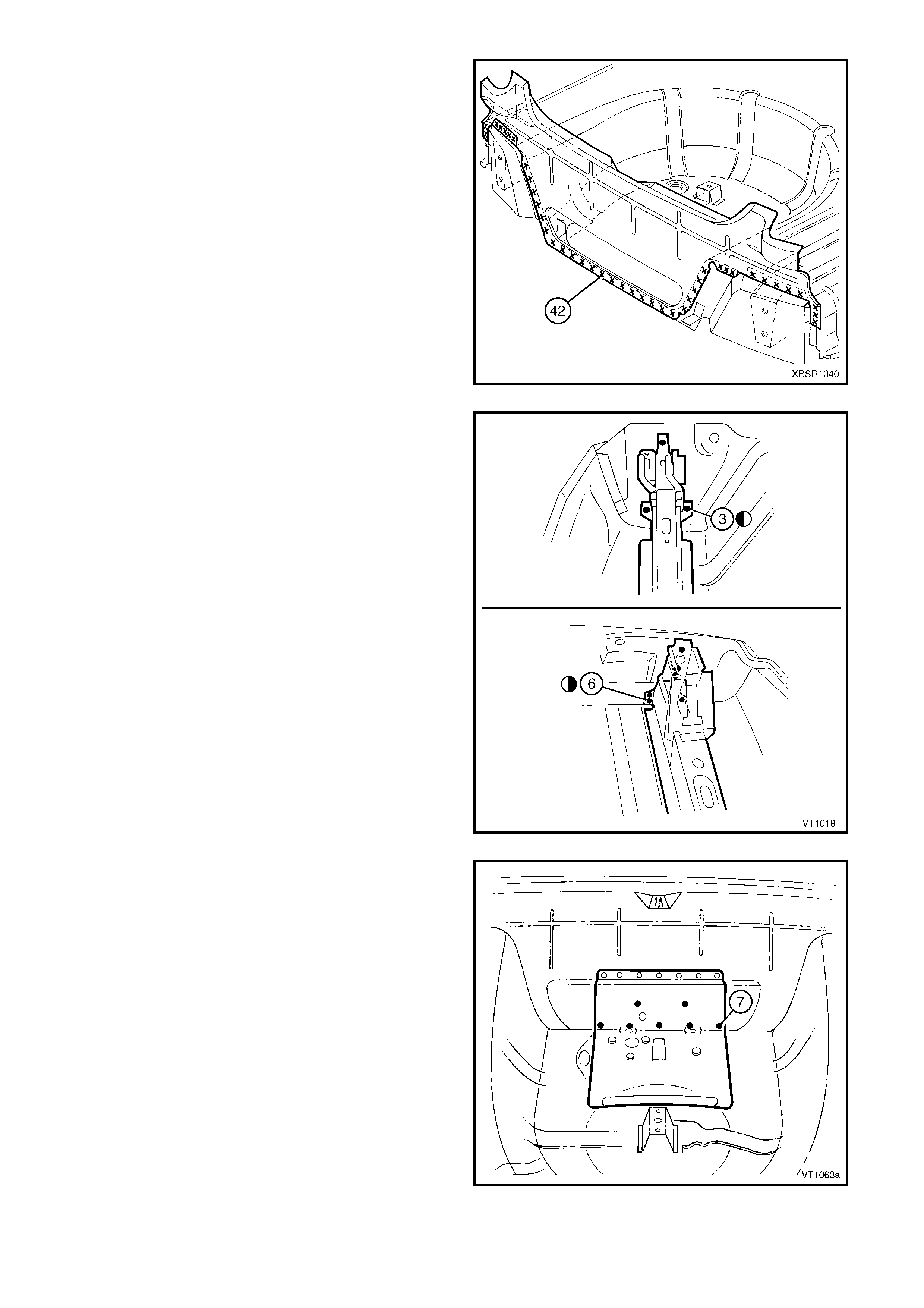
11. Apply Spray-on Deadener (Item 7) where
applicable, refer to 5. BODY SEALING,
ADHESIVES & DEADENERS in Section 3A.
12. Install the remaining components as described in
the appropriate Section of the MY 2003 VY & V2
Series II Service Information.
Figure 10A-26
2.6 REAR COMPARTMENT FLOOR PANEL ASSEMBLY– REPLACE
REMOVE
CAUTION: To avoid the possibility of fire, take
particular care when cutting or welding at the rear
of the vehicle. Remove the fuel tank and plug all
fuel lines.
1. Remove the adjacent bolt-on panels and
components as described in the appropriate
Section of the MY 2003 VY & V2 Series II Service
Information.
2. Secure the vehicle on a suitable fixture and use a
suitable brace to maintain the alignment of the rear
side rail assemblies prior to removal of the rear
end panel assembly.
3. Remove the rear end panel assembly, refer to
2.2 REAR END PANEL ASSEMBLY – REPLACE.
4. Remove the j oint sealer f rom the s urrounding area
using a scraper and heat gun.
5. As required, spot cut each rear compartment floor
panel outer extension from the rear wheelhouse
panel and rear quarter panel, refer to Figure
10A-28.
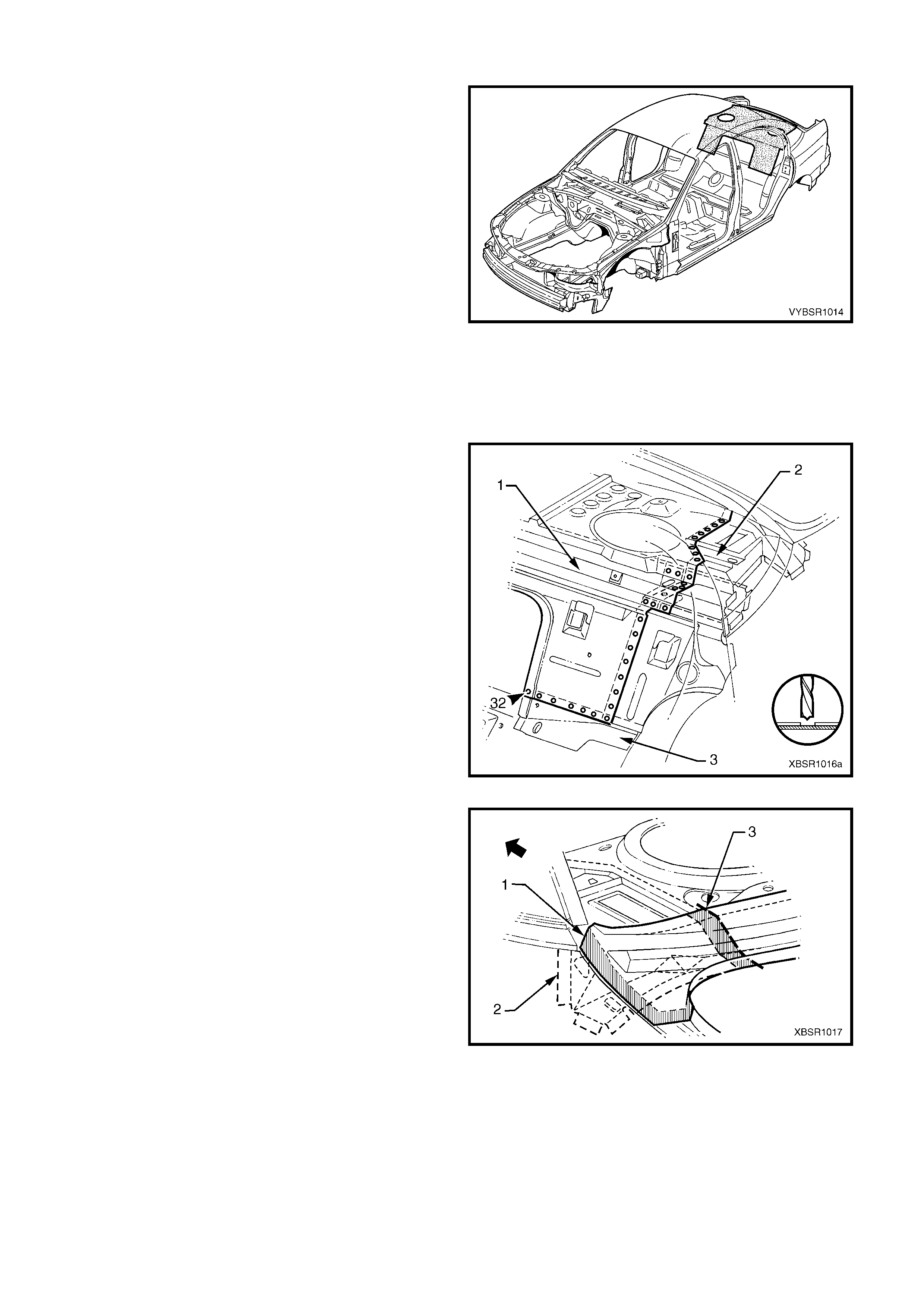
Figure 10A-27
Figure 10A-28
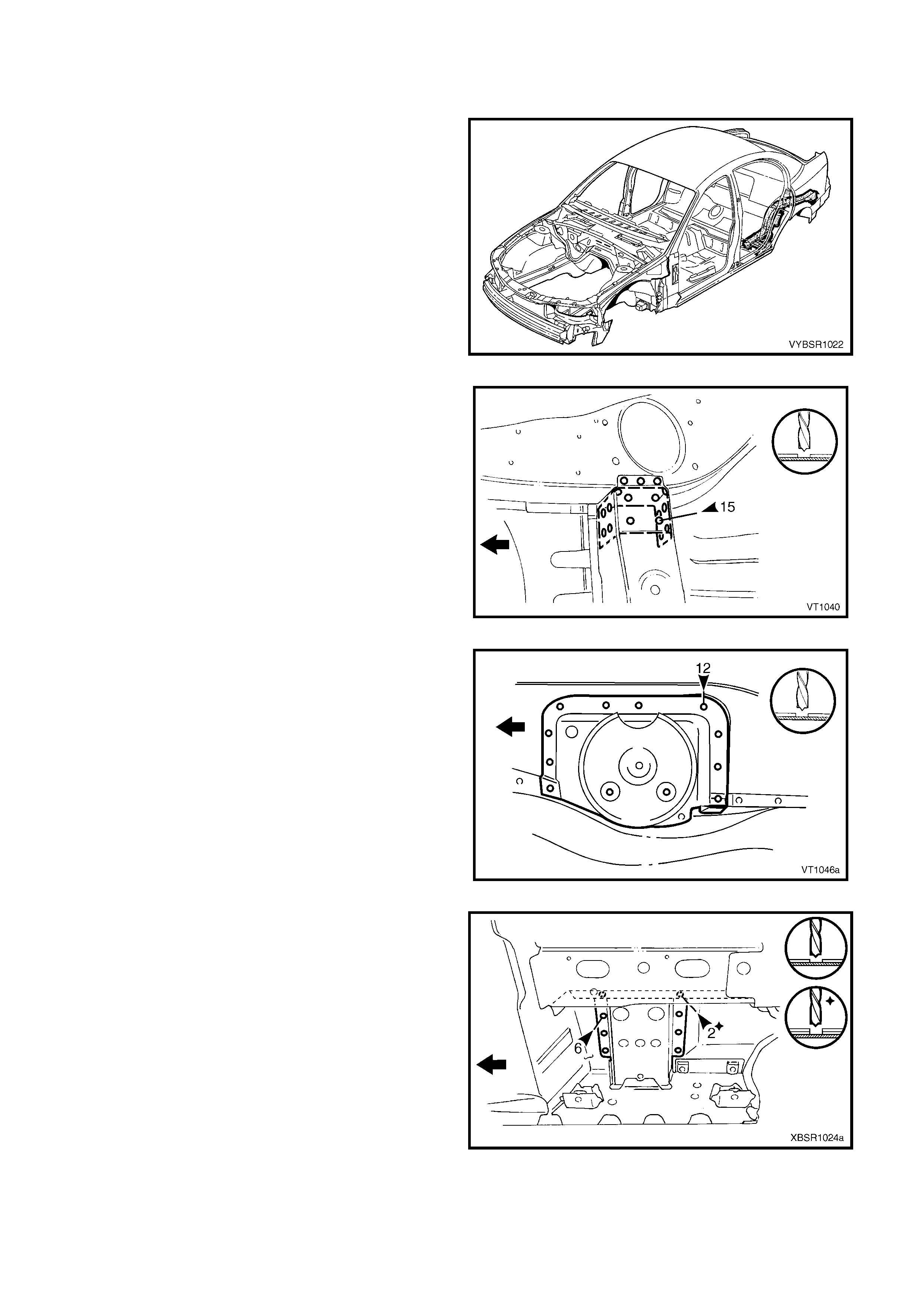
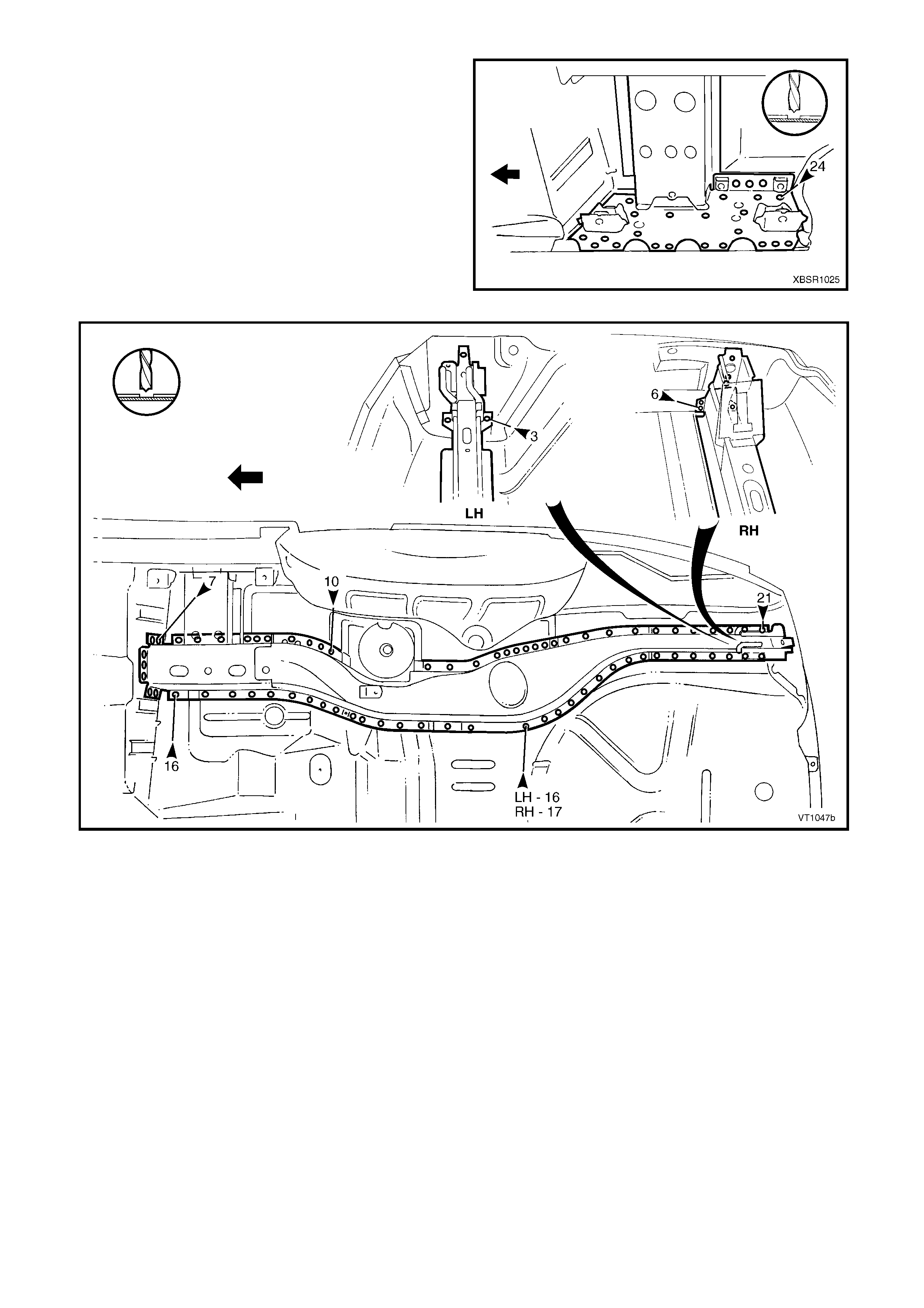
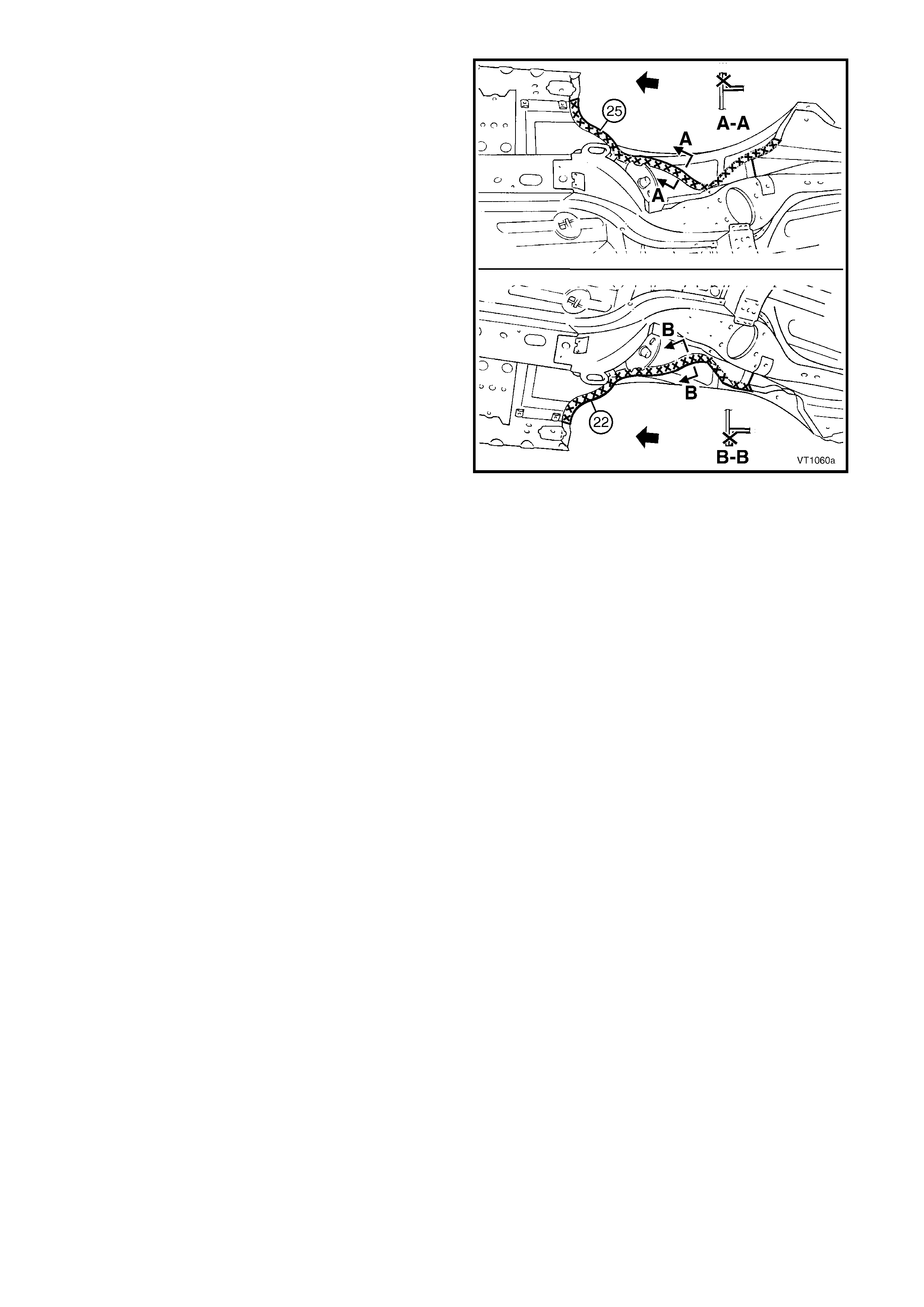
6. Spot cut the welds attaching the rear com partment f loor panel assem bly (1) to the rear floor panel as sem bly (2)
and to the rear side rail assemblies, refer to Figure 10A-29.
NOTE: Structural adhesive is applied in the area shown (3), refer to 5. BODY SEALING, ADHESIVES &
DEADENERS in Section 3A (Sedan).
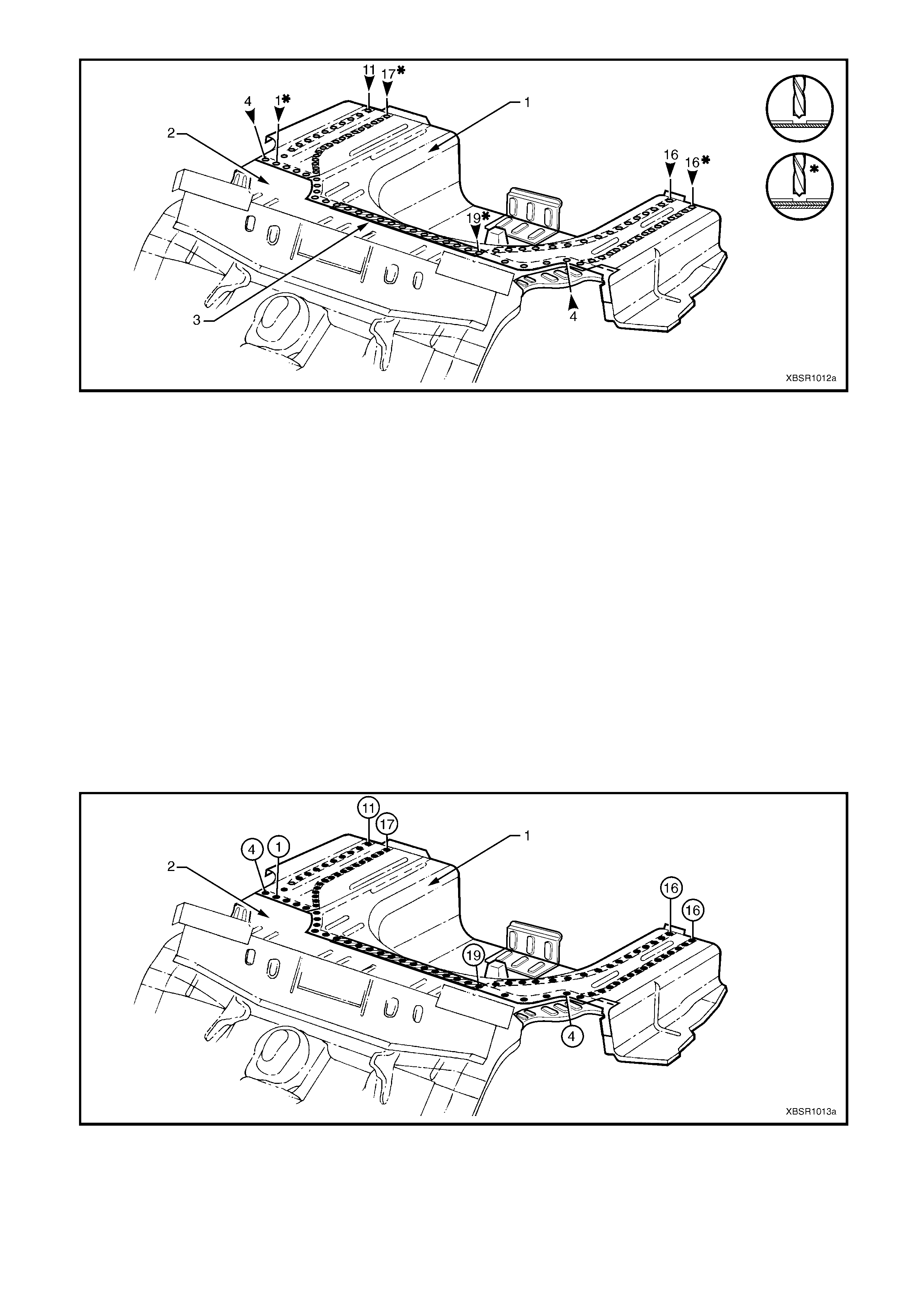
Figure 10A-29
7. Remove the rear compartment f loor panel assem bly f rom the vehicle and repair any damage to adjacent parts
as required.
8. Check and rectify the alignment of the body as required, refer to 3. BODY DIMENSIONS in Section 3A.
REPLACE
NOTE 1: Spot welding is the preferred method for attaching of panels and should be used whenever possible.
Where the spot welding equipment will not access the required weld position, a plug weld should be performed.
NOTE 2: The s am e num ber and pos ition of s pot welds (or plug welds) s hould be used when replac ing the panel, as
was used during manufacture, in order to maintain the original structural strength of the vehicle.
1. As required, mark the new panel with drilling locations in preparation for plug welding. Drill holes as required.
2. Prepare all mating surfaces and treat with Weld Through Primer (Item 1) as required, refer to
5. BODY SEALING, ADHESIVES & DEADENERS in Section 3A.
3. Apply Acrylic Spot W eld Sealer (Item 2), refer to 5. BODY SEALING, ADHESIVES & DEADENERS in Section
3A.
4. Apply Structural Adhesive (Item 6), refer to 5. BODY SEALING, ADHESIVES & DEADENERS in Section 3A.
5. Install the rear compartment floor panel assembly (1) ensuring it is seated under the left-hand rear floor panel
reinforcement.
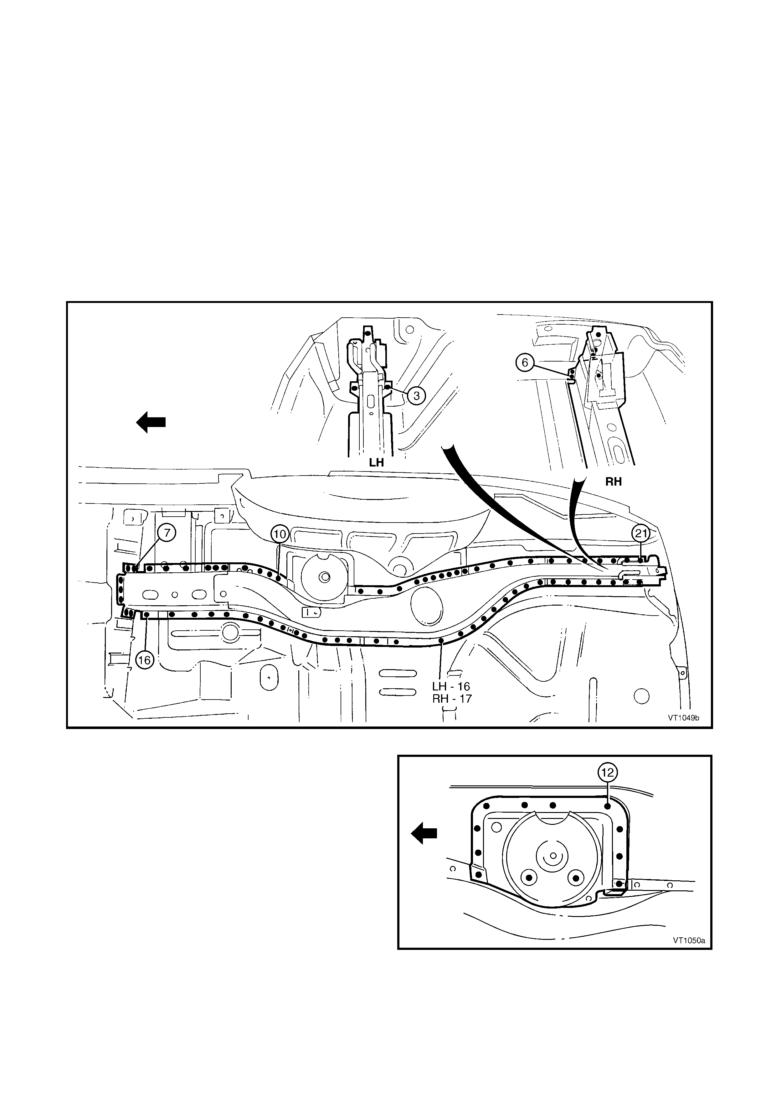
6. Plug weld along the join of the rear floor panel assembly (2) and to the rear side rail assemblies, refer to
Figure 10A-30.
Figure 10A-30
7. As r equired, s pot or plug weld eac h r ear c ompartment f loor panel outer ex tens ion to the rear wheelhouse panel,
rear quar ter panel, rear end panel assem bly and for the lef t-hand side, the rear f loor panel reinforcem ent, refer
to Figure 10A-31.
Figure 10A-31
8. Install the rear end panel and other panels as required, refer to the relevant procedure in this Supplement.
9. Refinish and paint panels and other components as required. Refer to Section 3, 1.3 PAINT REFINISHING.
10. Apply Joint Sealer (Item 3) as required. Refer to 5. BODY SEALING, ADHESIVES & DEADENERS in Section
3A.
11. Apply deadener panels to the r ear c ompartment f loor panel, r ef er to 5.6 DEADENER PANELS & INSULATORS
in Section 3A.
12. Apply Cavity W ax (Item 8) as required to the inside of any box sections or areas inaccessible to paint, refer to
6. CAVITY WAX in Section 3A.
13. Apply Spr ay-on Deadener (Item 7) where applic able, ref er to 5. BO DY SEALING, ADHESIVES & DEADENERS
in Section 3A.
14. Install the remaining components as described in the appropriate Section of the MY 2003 VY & V2 Series II
Service Information.
2.7 REAR WINDOW PANEL ASSEMBLY – REPLACE
Depending on the ar ea of damage, it may be advisable
to include removal of the rear seat back panel
extension assembly or rear wheelhouse inner panel
assembly. Refer to 2.8 REAR SEAT BACK PANEL
EXTENSION ASSEMBLY or REAR WHEELHOUSE
PANEL ASSEMBLY – REPLACE.
REMOVE
CAUTION: To avoid the possibility of fire, take
particular care when cutting or welding at the rear
of the vehicle. Remove the fuel tank and plug all
fuel lines.
1. Remove the adjacent bolt-on panels and
components as described in the appropriate
Section of the MY 2003 VY & V2 Series II Service
Information.
2. As required, remove adjoining body structure
panels, refer to the appropriate procedure in this
Supplement.
Figure 10A-32
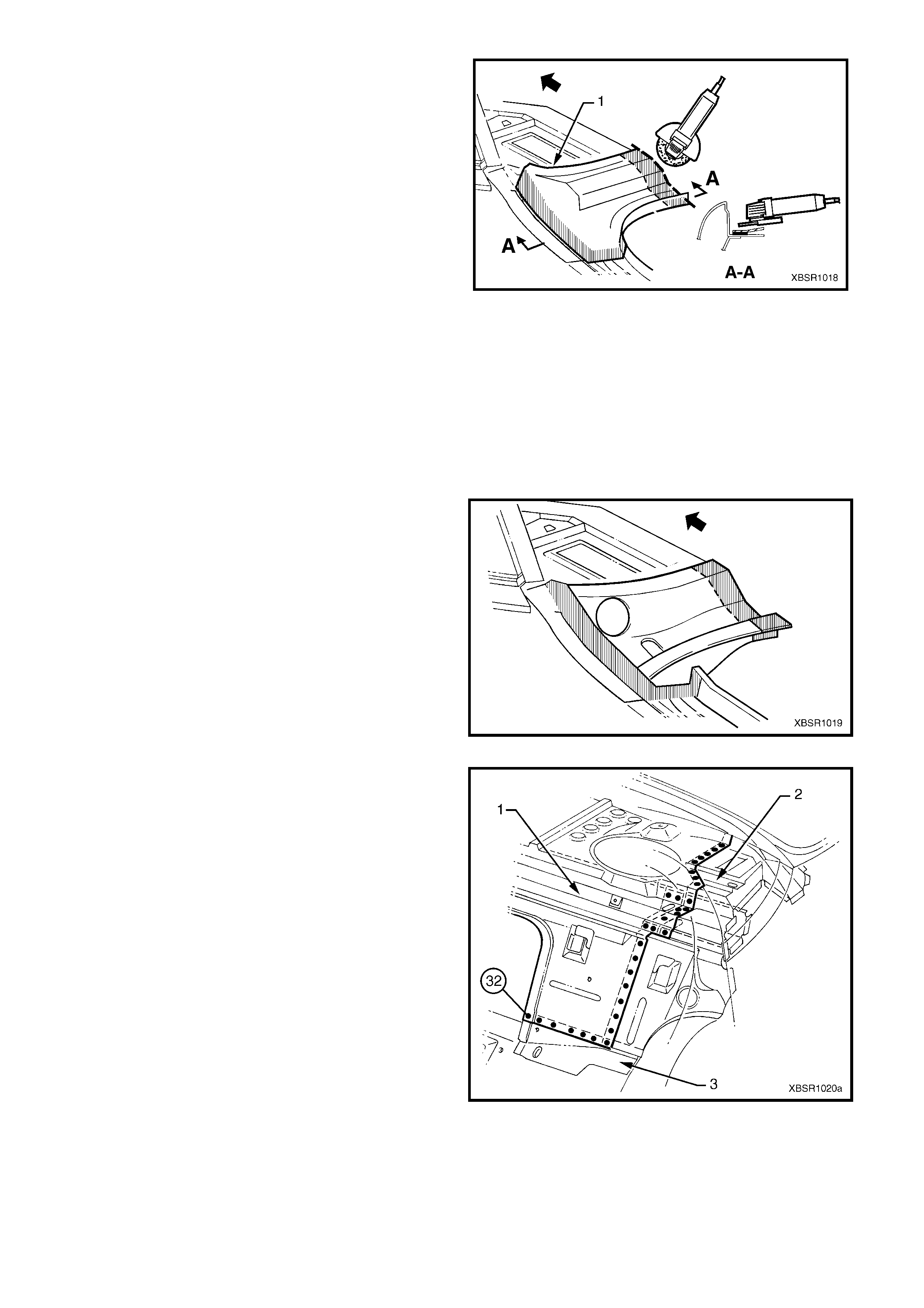
3. Remove the spot welds attaching the rear window
panel assembly (1) to the rear seat back panel
extension assembly (2) and the rear floor panel
assembly (3).
Figure 10A-33
IMPORTANT: The rear window panel assembly (1) is
attached to the rear seat back panel extension
assembly (2) and rear quarter panel with spot welding
and struc tural adhesive (s hown shaded). The adhesive
bond is not breakable by any normal means, so spot
cutting is not a viable method of removal of the panel.
4. Cut the rear window panel assembly inboard of the
join to the rear seat back panel extension
assembly with a grinder or other cutting tool along
line (3).
5. Remove the r ear window panel ass embly from the
vehicle.
Figure 10A-34
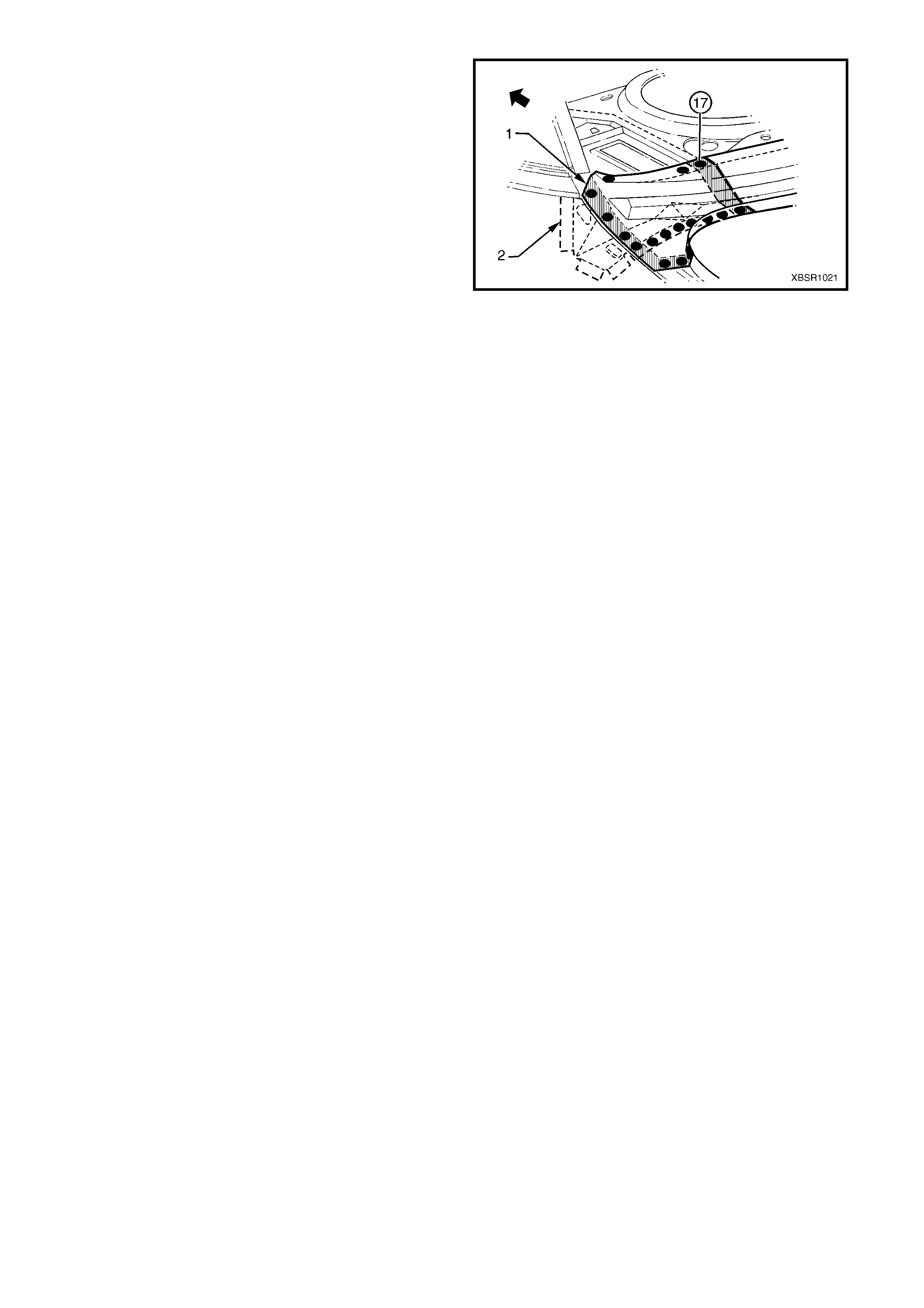
6. Using a grinder, remove the remaining portion of
the rear window panel assembly and the layer of
adhesive below it as required.
7. Repair any damage to adjacent parts as required.
8. Check and rectify the alignment of the body as
required, refer to 3. BODY DIMENSIONS in
Section 3A.
Figure 10A-35
REPLACE
NOTE 1: Spot welding is the preferred method for attaching of panels and should be used whenever possible.
Where the spot welding equipment will not access the required weld position, a plug weld should be performed.
NOTE 2: The s am e num ber and pos ition of s pot welds (or plug welds) s hould be used when replac ing the panel, as
was used during manufacture, in order to maintain the original structural strength of the vehicle.
1. As required, mark the new panel with drilling locations in preparation for plug welding. Drill holes as required.
2. Prepare all mating surfaces and treat with Weld Through Primer (Item 1) as required, refer to
5. BODY SEALING, ADHESIVES & DEADENERS in Section 3A.
3. Apply Structural adhesive (Item 6) to the areas
shown, refer to 5. BODY SEALING, ADHESIVES
& DEADENERS in Section 3A.
4. Clamp the rear window panel assem bly in position
on the vehicle.
Figure 10A-36
5. Spot or plug weld the rear window panel ass embly
(1) to the rear seat back panel extension assembly
(2) and the rear floor panel assembly (3).
Figure 10A-37
6. Spot or plug weld the rear window panel ass embly
(1) to the rear seat back extens ion panel assem bly
(2).
7. Refinish and paint panels and other components
as required. Refer to Section 3, 1.3 PAINT
REFINISHING.
8. Apply Joint Sealer (Item 3) as required. Refer to
5. BODY SEALING, ADHESIVES & DEADENERS
in Section 3A.
9. Apply Cavity Wax ( Item 8) as requir ed to the inside
of any box sections or areas inaccessible to paint,
refer to 6. CAVITY WAX in Section 3A.
10. Install the remaining components as described in
the appropriate Section of the MY 2003 VY & V2
Series II Service Information.
Figure 10A-38
2.8 REAR SEAT BACK PANEL EXTENSION ASSEMBLY or REAR WHEELHOUSE
INNER PANEL ASSEMBLY – REPLACE
REMOVE
1. Remove the adjacent bolt-on panels and
components as described in the appropriate
Section of the MY 2003 VY & V2 Series II Service
Information.
2. Either remove, or detach the rear window panel
assembly from the rear seat back panel extension
assembly, refer to Section 2.7 REAR WINDOW
PANEL ASSEMBLY – REPLACE.
Figure 10A-39
3. Spot cut the welds attaching the rear seat back
panel extension assembly to the quarter panel
inner assembly.
Figure 10A-40
4. Spot cut the three welds attaching the rear seat
back panel extension assembly to the rear floor
panel assembly.
5. If the rear seat back panel extension assembly is
to be replaced without the rear wheelhouse inner
panel, spot cut the ten welds attaching the
extension assembly to the rear wheelhouse inner
panel assembly.
6. Remove the rear seat back panel extension
assembly, if it is being replaced without the rear
wheelhouse inner panel assembly.
7. If the rear wheelhouse inner panel assembly is
being replaced, spot cut the welds attaching it to
the rear floor panel assembly and rear
compartment floor panel outer extension as
required, refer to Figure 10A-42.
Figure 10A-41
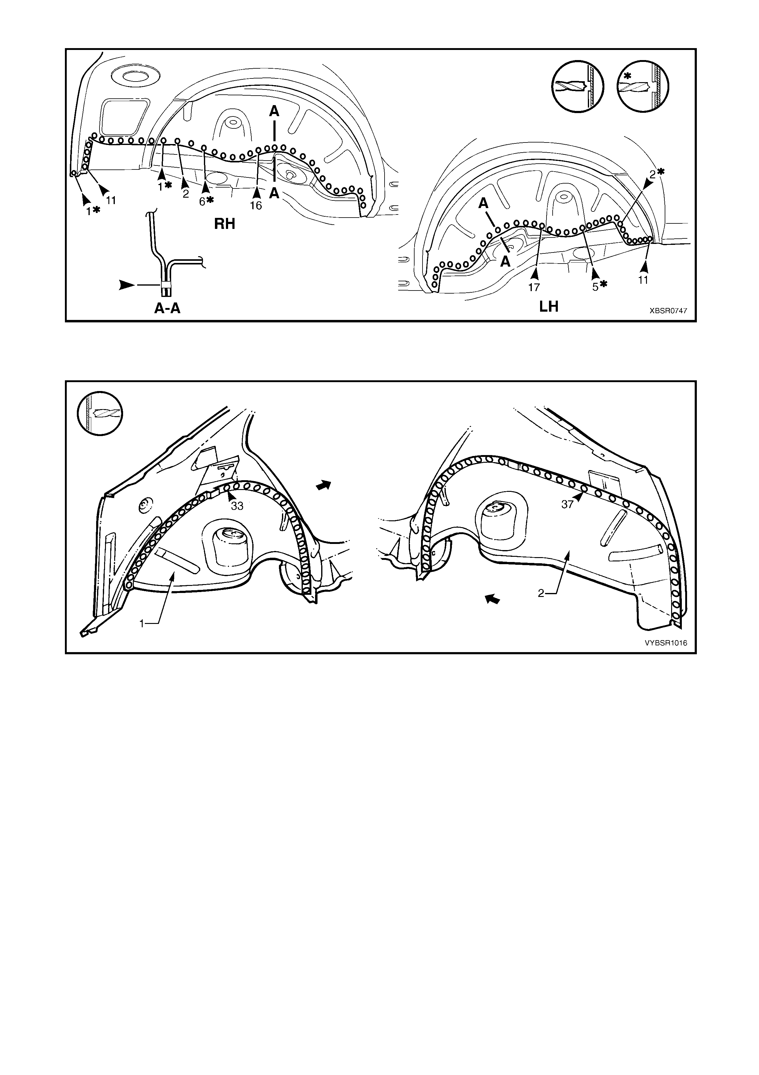
Figure 10A-42
8. Spot cut the welds attaching the rear wheelhouse inner assembly to the quarter panel inner assembly, refer to
Figure 10A-43.
Figure 10A-43
9. Remove the rear wheelhouse inner assembly.
10. Repair any damage to adjacent parts as required.
11. Check and rectify the alignment of the body as required, refer to 3. BODY DIMENSIONS in Section 3A.
REPLACE
NOTE 1: Spot welding is the preferred method for attaching of panels and should be used whenever possible.
Where the spot welding equipment will not access the required weld position, a plug weld should be performed.
NOTE 2: The s am e num ber and pos ition of s pot welds (or plug welds) s hould be used when replac ing the panel, as
was used during manufacture, in order to maintain the original structural strength of the vehicle.
1. As required, mark the new panel with drilling locations in preparation for plug welding. Drill holes as required.
2. Prepare all mating surfaces and treat with Weld Through Primer (Item 1) as required, refer to
5. BODY SEALING, ADHESIVES & DEADENERS in Section 3A.
3. If the rear wheelhouse inner assembly is being replaced, spot or plug weld around the rear wheelhouse inner
assembly to the quarter panel inner assembly, refer to Figure 10A-44.
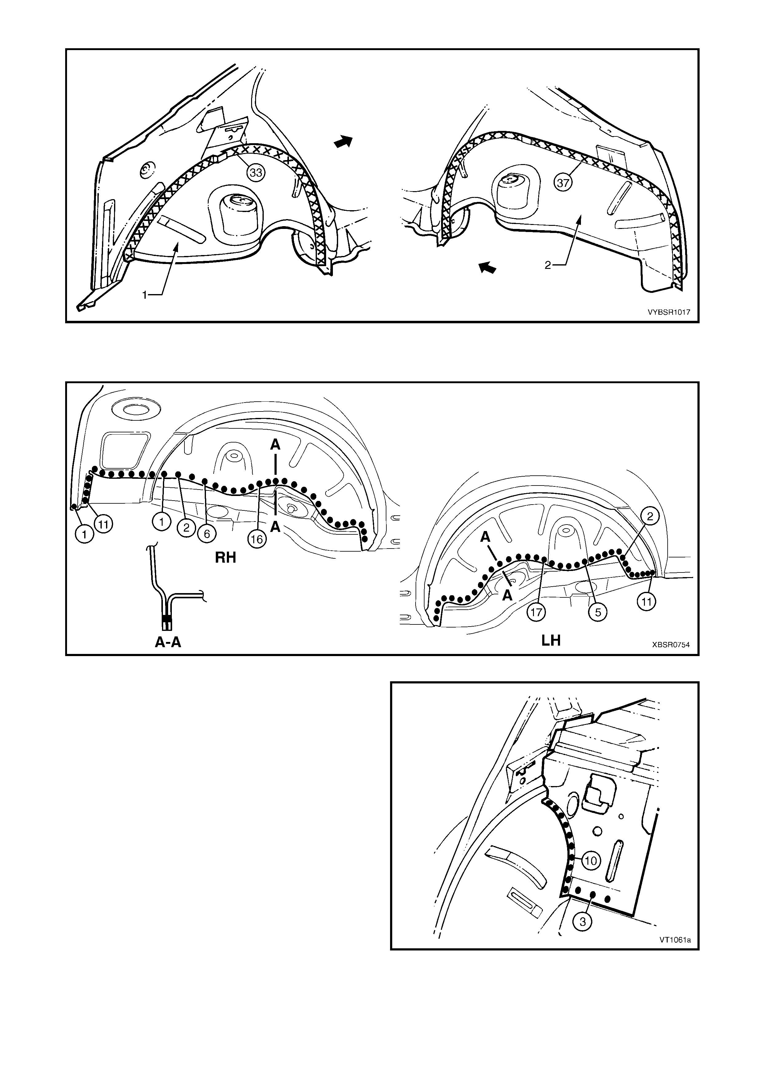
Figure 10A-44
4. Spot or plug weld the rear wheelhouse inner assembly to the rear floor panel assembly and rear compartment
floor panel outer extension, refer to Figure 10A-45.
Figure 10A-45
5. Plug weld three places, rear seat back panel
extension assembly to the rear floor panel
assembly.
6. If the rear seat back panel extension assembly is
being replaced without the rear wheelhouse inner
panel, plug weld ten places.
Figure 10A-46
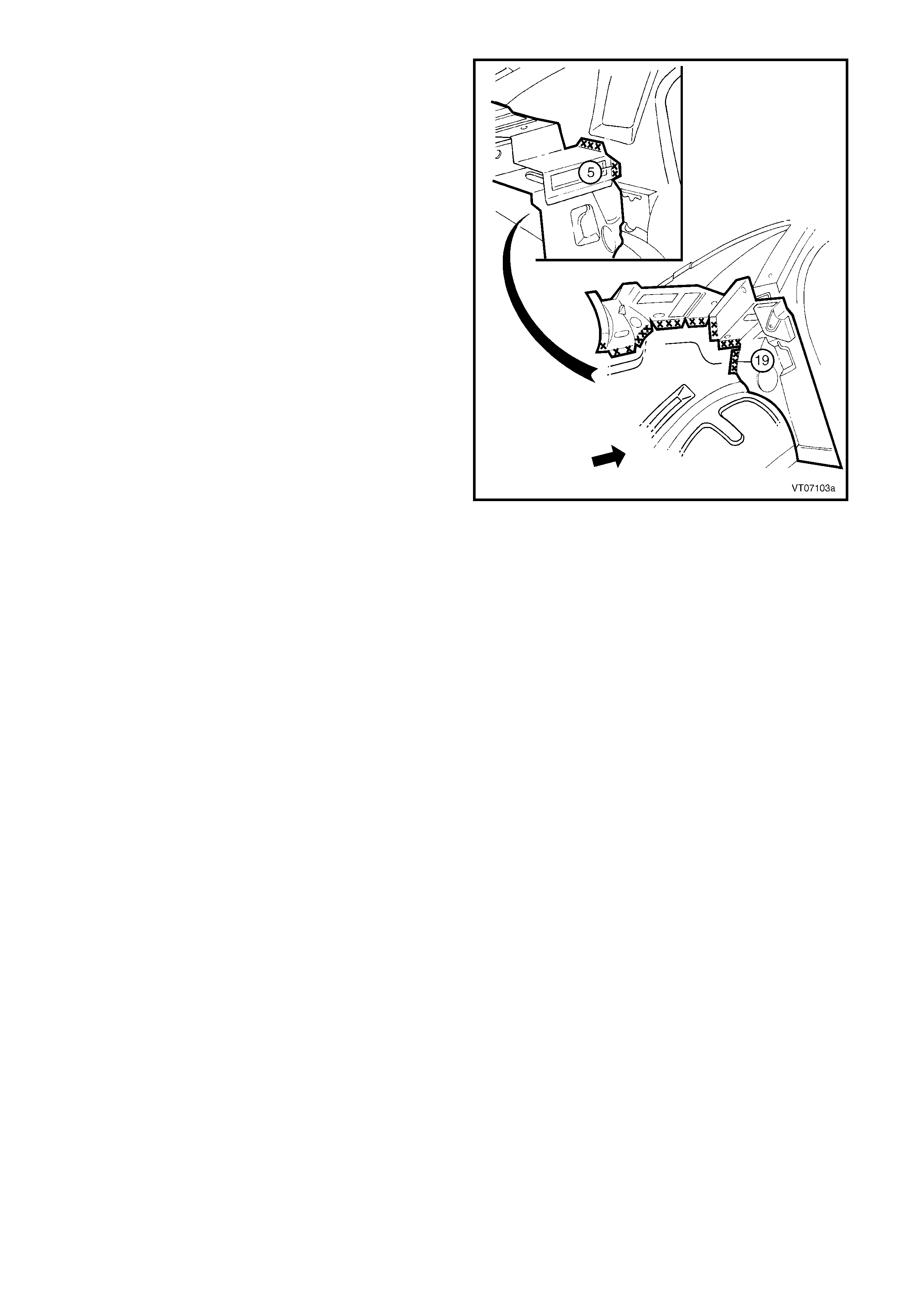
7. Spot or plug weld the rear seat back panel
extension assembly to the quarter panel inner
assembly.
8. Install, or weld the rear window panel assem bly, to
the rear seat back panel extension, refer to
Section, 2.7 REAR WINDOW PANEL ASSEMBLY
– REPLACE.
9. Refinish and paint panels and other components
as required. Refer to Section 3, 1.3 PAINT
REFINISHING.
10. Apply Joint Sealer (Item 3) as required. Refer to
5. BODY SEALING, ADHESIVES & DEADENERS
in Section 3A.
11. Apply Cavity Wax (Item 8) as r equired to the inside
of any box sections or areas inaccessible to paint,
refer to 6. CAVITY WAX in Section 3A.
12. Install the remaining components as described in
the appropriate Section of the MY 2003 VY & V2
Series II Service Information.
Figure 10A-47
2.9 REAR COMPARTMENT LID STRUT BRACKET ASSEMBLY – REPLACE
REMOVE
1. Remove the adjacent bolt-on panels and
components as described in the appropriate
Section of the MY 2003 VY & V2 Series II Service
Information.
2. Spot cut the welds attaching the rear compar tment
lid strut bracket assembly to the rear seat back
panel extension assembly.
3. Remove the rear compartment lid strut bracket
assembly from the vehicle and repair any damage
to adjacent parts as required.
Figure 10A-48
REPLACE
NOTE 1: Spot welding is the preferred method for attaching of panels and should be used whenever possible.
Where the spot welding equipment will not access the required weld position, a plug weld should be performed.
NOTE 2: The s am e num ber and pos ition of s pot welds (or plug welds) s hould be used when replac ing the panel, as
was used during manufacture, in order to maintain the original structural strength of the vehicle.
1. As required, mark the new panel with drilling locations in preparation for plug welding. Drill holes as required.
2. Prepare all mating surfaces and treat with Weld Through Primer (Item 1) as required, refer to
5. BODY SEALING, ADHESIVES & DEADENERS in Section 3A.
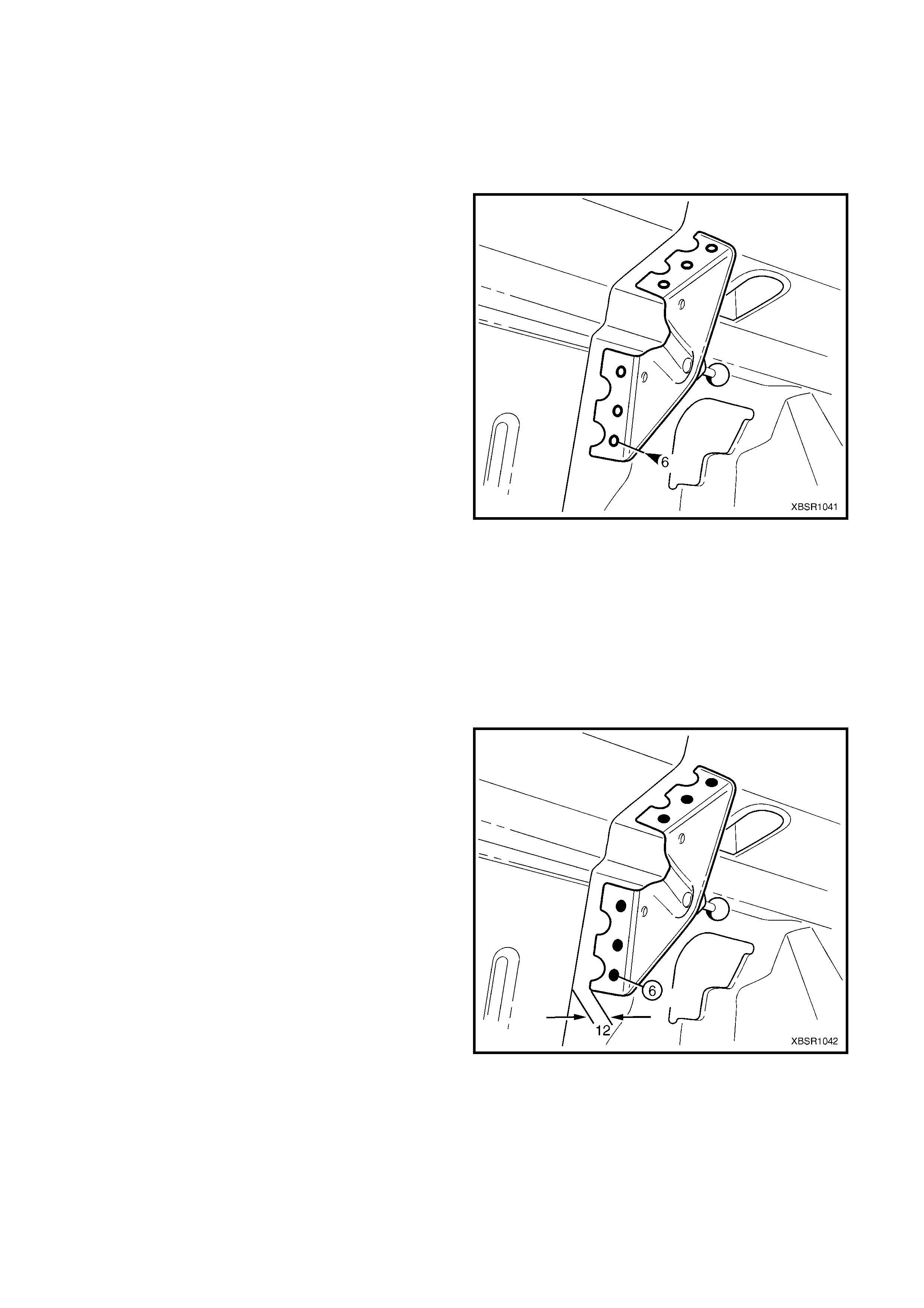
3. Install the rear compartment lid strut bracket
assembly, positioning it approximately 12mm from
the edge of the rear seat back panel extension
assembly.
4. Plug weld the rear compartment lid strut bracket
assembly to the rear seat back panel extension
assembly six places.
5. Refinish and paint panels and other components
as required. Refer to Section 3, 1.3 PAINT
REFINISHING.
6. Apply Cavity Wax ( Item 8) as requir ed to the inside
of any box sections or areas inaccessible to paint,
refer to 6. CAVITY WAX in Section 3A.
7. Install the remaining components as described in
the appropriate Section of the MY 2003 VY & V2
Series II Service Information.
Figure 10A-49
2.10 CROSSMEMBER ASSEMBLY NO. 2 – REPLACE
REMOVE
CAUTION: To avoid the possibility of fire, take
particular care when cutting or welding at the rear
of the vehicle. Remove the fuel tank and plug all
fuel lines.
1. Remove the adjacent components as described in
the appropriate Section of the MY 2003 VY & V2
Series II Service Information.
2. Secure the vehicle on a suitable fixture. As a
minimum, support the appropriate structural
sections of the vehicle on safety stands.
Figure 10A-50
3. Spot cut the welds attaching the crossmember
No.2 to the crossmember bracket and to the rear
side rail, on each side of the vehicle.
NOTE: Take care not to damage the crossmember
brackets when removing the crossmember, as these
parts are only serviced as part of the rear side rail
assemblies.
Figure 10A-51
4. Spot cut the welds attaching the crossmember to
the rear compartment floor panel assembly.
5. Remove the crossmember from the vehicle, and
then repair any damage to adjacent parts as
required.
6. Check and rectify the alignment of the body as
required, refer to 3. BODY DIMENSIONS in
Section 3A.
Figure 10A-52
REPLACE
NOTE 1: Spot welding is the preferred method for attaching of panels and should be used whenever possible.
Where the spot welding equipment will not access the required weld position, a plug weld should be performed.
NOTE 2: The s am e num ber and pos ition of s pot welds (or plug welds) s hould be used when replac ing the panel, as
was used during manufacture, in order to maintain the original structural strength of the vehicle.
1. As required, mark the new panel with drilling locations in preparation for plug welding. Drill holes as required.
2. Prepare all mating surfaces and treat with Weld Through Primer (Item 1) as required, refer to
5. BODY SEALING, ADHESIVES & DEADENERS in Section 3A.
3. Plug weld the crossmember to the crossmember
bracket and rear side rail, on each side of the
vehicle.
Figure 10A-53
4. Plug weld the crossmember to the rear
compartment floor panel assembly.
5. Refinish and paint panels and other components
as required. Refer to Section 3, 1.3 PAINT
REFINISHING.
6. Apply Joint Sealer (Item 3) as required. Refer to
5. BODY SEALING, ADHESIVES & DEADENERS
in Section 3A.
7. Apply Cavity Wax ( Item 8) as requir ed to the inside
of any box sections or areas inaccessible to paint,
refer to 6. CAVITY WAX in Section 3A.
8. Apply Spray-on Deadener (Item 7) where
applicable, refer to 5. BODY SEALING,
ADHESIVES & DEADENERS in Section 3A.
9. Install the remaining components as described in
the appropriate Section of the MY 2003 VY & V2
Series II Service Information.
Figure 10A-54
2.11 REAR FLOOR PANEL OUTER EXTENSION – REPLACE
REMOVE
1. Remove the adjacent components as described in
the appropriate Section of the MY 2003 VY & V2
Series II Service Information.
Figure 10A-55
2. Spot cut the welds attaching the rear floor panel
outer extension to the inner rocker panel and rear
side rail assembly and remove.
Figure 10A-56
REPLACE
NOTE 1: Spot welding is the preferred method for attaching of panels and should be used whenever possible.
Where the spot welding equipment will not access the required weld position, a plug weld should be performed.
NOTE 2: The s am e num ber and pos ition of s pot welds (or plug welds) s hould be used when replac ing the panel, as
was used during manufacture, in order to maintain the original structural strength of the vehicle.
1. As required, mark the new panel with drilling locations in preparation for plug welding. Drill holes as required.
2. Prepare all mating surfaces and treat with Weld Through Primer (Item 1) as required, refer to
5. BODY SEALING, ADHESIVES & DEADENERS in Section 3A.
3. Install and plug weld the rear floor panel outer
extension to the inner rocker panel and rear side
rail assembly.
4. Refinish and paint panels and other components
as required. Refer to Section 3, 1.3 PAINT
REFINISHING.
5. Apply Cavity Wax ( Item 8) as requir ed to the inside
of any box sections or areas inaccessible to paint,
refer to 6. CAVITY WAX in Section 3A.
6. Install the remaining components as described in
the appropriate Section of the MY 2003 VY & V2
Series II Service Information.
Figure 10A-57
2.12 REAR TIE DOWN ASSEMBLY – REPLACE
REMOVE
1. Remove the adjacent components as described in
the appropriate Section of the MY 2003 VY & V2
Series II Service Information.
Figure 10A-58
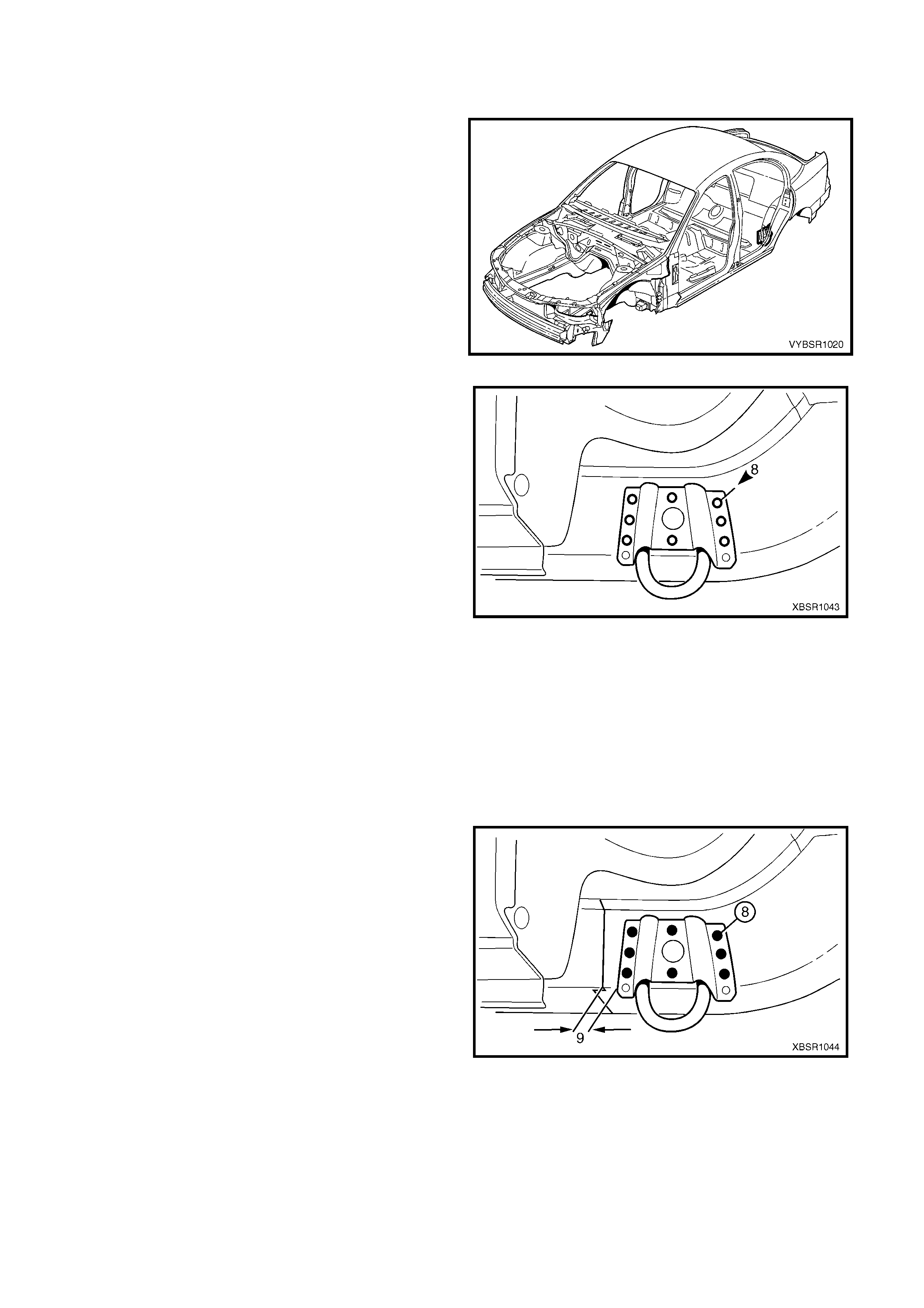
2. Spot cut the welds attaching the tie down hook
assembly to the rear side rail assembly and
remove.
Figure 10A-59
REPLACE
NOTE 1: Spot welding is the preferred method for attaching of panels and should be used whenever possible.
Where the spot welding equipment will not access the required weld position, a plug weld should be performed.
NOTE 2: The s am e num ber and pos ition of s pot welds (or plug welds) s hould be used when replac ing the panel, as
was used during manufacture, in order to maintain the original structural strength of the vehicle.
1. As required, mark the new panel with drilling locations in preparation for plug welding. Drill holes as required.
2. Prepare all mating surfaces and treat with Weld Through Primer (Item 1) as required, refer to
5. BODY SEALING, ADHESIVES & DEADENERS in Section 3A.
3. Install the tie down hook assembly onto the rear
side rail assembly, approximately 9 mm rearward
of the join.
4. Plug weld the tie down hook assembly to the rear
side rail assembly, eight places.
5. Refinish and paint panels and other components
as required. Refer to Section 3, 1.3 PAINT
REFINISHING.
6. Apply Cavity Wax ( Item 8) as requir ed to the inside
of any box sections or areas inaccessible to paint,
refer to 6. CAVITY WAX in Section 3A.
7. Install the remaining components as described in
the appropriate Section of the MY 2003 VY & V2
Series II Service Information.
Figure 10A-60
2.13 REAR BUMPER IMPACT BAR BRACE ASSEMBLY – REPLACE
REMOVE
CAUTION: To avoid the possibility of fire, take
particular care when cutting or welding at the rear
of the vehicle. Remove the fuel tank and plug the
fuel lines.
1. Remove the adjacent bolt-on panels and
components as described in the appropriate
Section of the MY 2003 VY & V2 Series II Service
Information.
2. Secure the vehicle on a suitable fixture. As a
minimum, support the appropriate structural
sections of the vehicle on safety stands. Ensure
that the stands are clear of the sections being
removed.
3. Remove the adjoining panels as required, refer to
the appropriate Section of this Supplement.
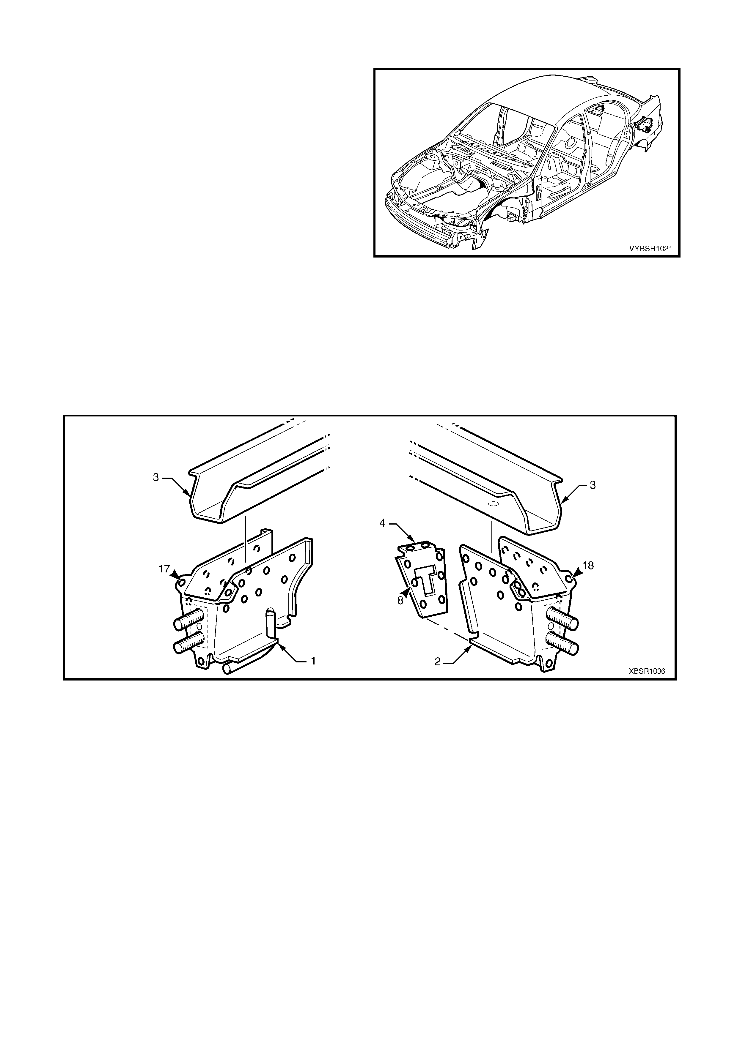
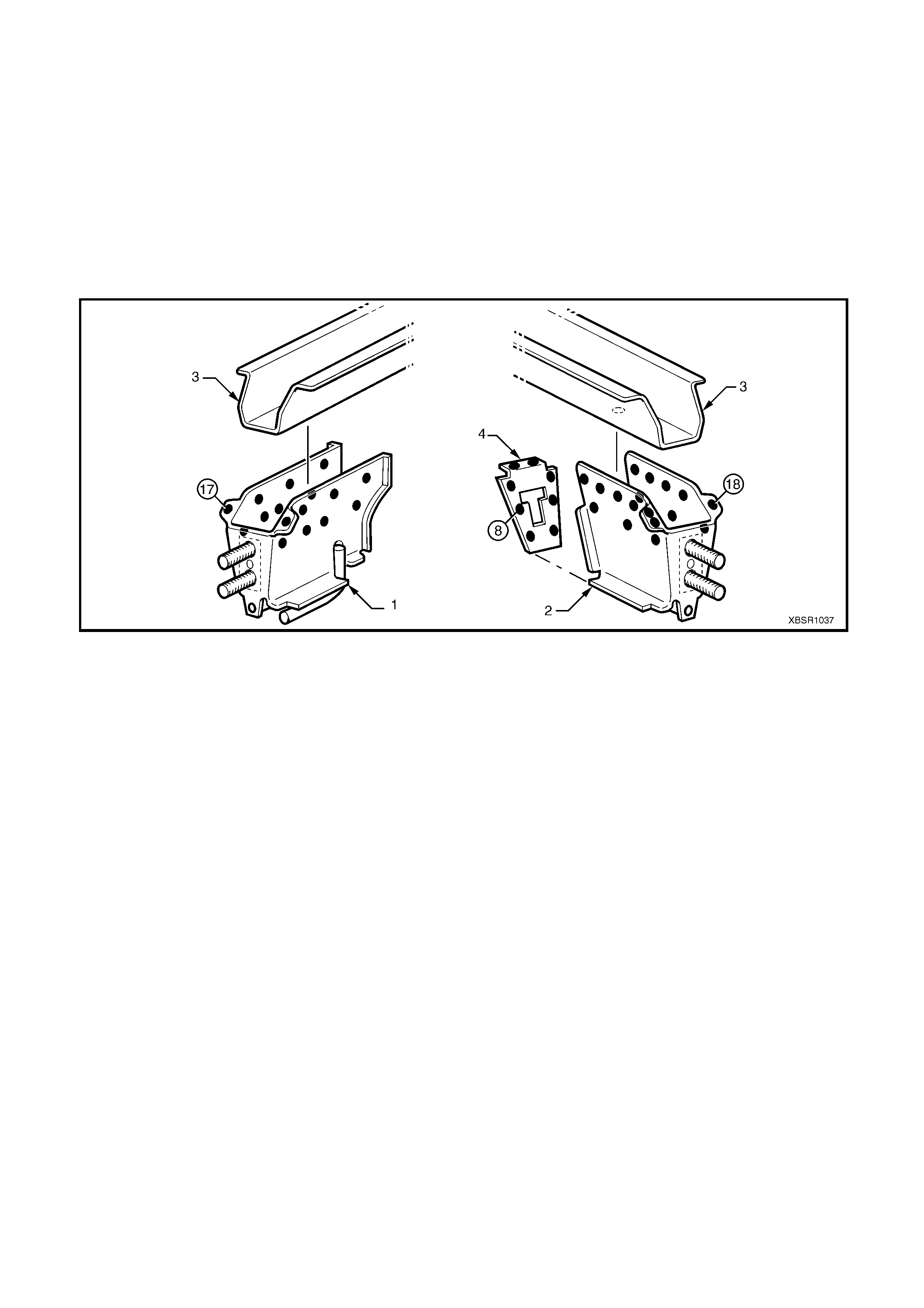
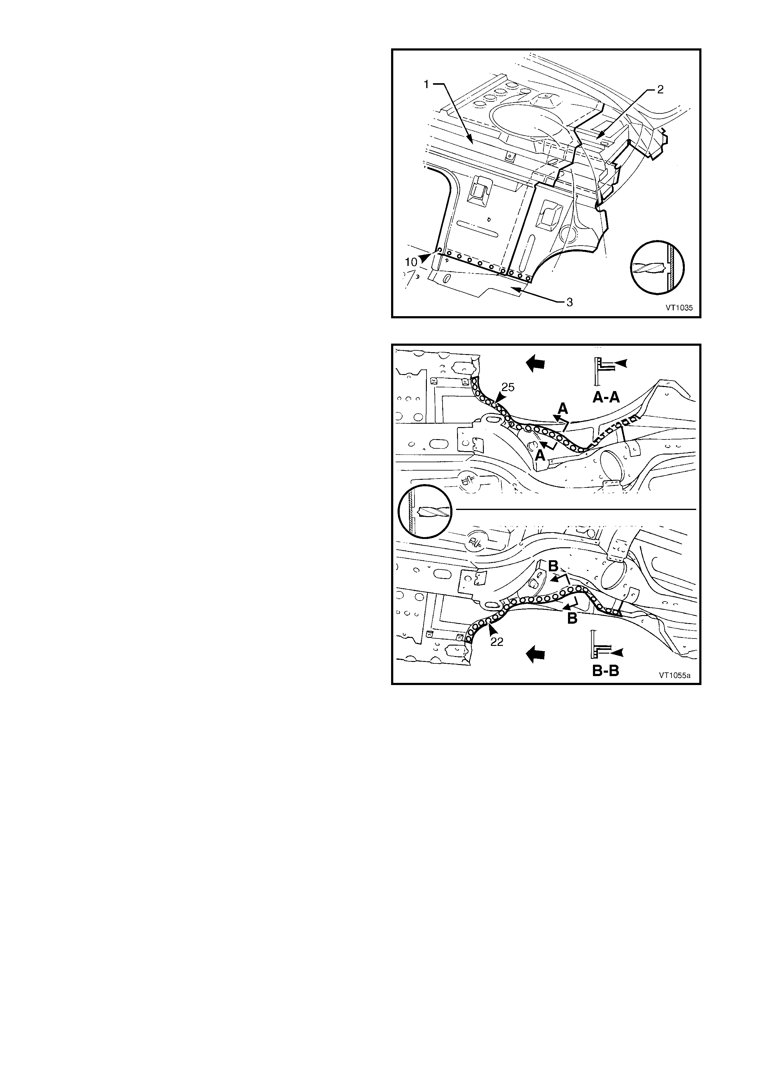
4. Spot cut the welds attaching the left-hand (1) or
right-hand (2) rear bumper impact bar brace
assembly to the rear side rail ass embly (3), refer to
Figure 10A-62.
5. If required, for the right-hand rear bumper impact
bar brace assembly , remove the closing plate (4).
Figure 10A-61
Figure 10A-62
REPLACE
NOTE 1: Spot welding is the preferred method for attaching of panels and should be used whenever possible.
Where the spot welding equipment will not access the required weld position, a plug weld should be performed.
NOTE 2: The s am e num ber and pos ition of s pot welds (or plug welds) s hould be used when replac ing the panel, as
was used during manufacture, in order to maintain the original structural strength of the vehicle.
1. As required, mark the new panel with drilling locations in preparation for plug welding. Drill holes as required.
2. Prepare all mating surfaces and treat with Weld Through Primer (Item 1) as required, refer to
5. BODY SEALING, ADHESIVES & DEADENERS in Section 3A.
3. Clamp and plug weld the rear bumper impact bar brace assembly (1 or 2) in position on the rear side rail
assembly (3).
4. If required, for the right-hand side clamp and plug weld the closing plate (4) in position, refer to Figure 10A-63.
Figure 10A-63
5. Install other panels as required, refer to the appropriate Section in this Supplement.
6. Refinish and paint panels and other components as required. Refer to Section 3, 1.3 PAINT REFINISHING.
7. Apply Joint Sealer (Item 3) as required. Refer to 5. BODY SEALING, ADHESIVES & DEADENERS in Section
3A.
8. Apply Cavity W ax (Item 8) as required to the inside of any box sections or areas inaccessible to paint, refer to
6. CAVITY WAX in Section 3A.
9. Install the remaining components as described in the appropriate Section of the MY 2003 VY & V2 Series II
Service Information.
2.14 REAR SIDE RAIL ASSEMBLY – REPLACE
REMOVE
CAUTION: To avoid the possibility of fire, take
particular care when cutting or welding at the rear
of the vehicle. Remove the fuel tank and plug all
fuel lines.
1. Remove the adjacent components as described in
the appropriate Section of the MY 2003 VY & V2
Series II Service Information.
2. Secure the vehicle on a suitable fixture. As a
minimum, support the appropriate structural
sections of the vehicle on safety stands. Ensure
that the stands are clear of the rear side rail
assembly(s) being removed.
Figure 10A-64
3. Spot cut the welds attaching the crossmember
No.2 to the crossmember bracket and to the rear
side rail, on each side of the vehicle.
Figure 10A-65
4. Spot cut the welds attaching the rear side rail
assembly to the rear floor panel assembly.
Figure 10A-66
5. Spot cut the welds attaching the rear side rail
assembly to the rear floor panel assembly.
Figure 10A-67
6. Spot cut the welds attaching the rear floor panel
outer extension to the inner rocker panel
assembly.
7. Spot cut the rear side rail assembly from the rear
floor panel assembly, rear compartment floor
panel assembly and the rear end panel, refer to
Figure 10A-69.
NOTE: Ther e are a dif f erent num ber of welds between
the left-hand and right-hand sides.
8. Remove the rear side rail assembly from the
vehicle.
Figure 10A-68
Figure 10A-69
9. Repair any damage to adjacent parts as required.
10. Check and rectify the alignment of the body as required, refer to 3. BODY DIMENSIONS in Section 3A.
REPLACE
NOTE 1: Spot welding is the preferred method for attaching of panels and should be used whenever possible.
Where the spot welding equipment will not access the required weld position, a plug weld should be performed.
NOTE 2: The s am e num ber and pos ition of s pot welds (or plug welds) s hould be used when replac ing the panel, as
was used during manufacture, in order to maintain the original structural strength of the vehicle.
1. As required, mark the new panel with drilling locations in preparation for plug welding. Drill holes as required.
2. Prepare all mating surfaces and treat with Weld Through Primer (Item 1) as required, refer to
5. BODY SEALING, ADHESIVES & DEADENERS in Section 3A.
CAUTION: Prior to plug welding in this region, remove the deadener from the inside floor to remove the risk
of fire.
3. Locate and clamp the new rear side rail assembly in position and check and adjust its alignment, refer to
3. BODY DIMENSIONS in Section 3A.
4. Plug weld the rear side rail assembly to the rear floor panel assembly, rear compartm ent floor panel assembly
and the rear end panel, refer to Figure 10A-70.
Figure 10A-70
5. Plug weld the rear side rail assembly to the rear
floor panel assembly.
Figure 10A-71
6. Plug weld the crossm em ber assem bly No. 2 to the
crossmember bracket and rear side rail.
Figure 10A-72
7. Plug weld the rear side rail assembly to the rear
floor panel ass embly and the rear floor panel outer
extension to the inner rocker panel assembly.
8. Refinish and paint panels and other components
as required. Refer to Section 3, 1.3 PAINT
REFINISHING.
9. Apply Joint Sealer (Item 3) as required. Refer to
5. BODY SEALING, ADHESIVES & DEADENERS
in Section 3A.
10. Apply Cavity Wax (Item 8) as r equired to the inside
of any box sections or areas inaccessible to paint,
refer to 6. CAVITY WAX in Section 3A.
11. Install the remaining components as described in
the appropriate Section of the MY 2003 VY & V2
Series II Service Information.
Figure 10A-73
2.15 REAR FLOOR PANEL ASSEMBLY – REPLACE
REMOVE
CAUTION: To avoid the possibility of fire, take
particular care when cutting or welding at the rear
of the vehicle. Remove the fuel tank and plug the
fuel lines.
1. Remove the adjacent bolt-on panels and
components as described in the appropriate
Section of the MY 2003 VY & V2 Series II Service
Information.
2. Secure the vehicle on a suitable fixture. As a
minimum, support the appropriate structural
sections of the vehicle on safety stands. Ensure
that the stands are clear of the sections being
removed.
3. Rem ove the sealer and deadener panels from the
relevant areas using a scraper and heat gun.
4. Remove the adjoining panels as required, refer to
the appropriate Section of this Supplement.
Figure 10A-74
5. Spot cut the welds attaching the park brake cable
bracket to the rear floor panel assembly.
Figure 10A-75
6. Spot cut the welds joining the front floor panel
assembly (1) and rear floor panel assembly (2).
7. Spot cut the welds attaching the rear floor panel
assembly to the inner rocker panel (3) each side.
Figure 10A-76
8. Spot cut the welds attaching the rear floor panel
assembly (3), to the rear window panel assembly
(1) and the rear seat back panel extension
assembly (2).
Figure 10A-77
9. Spot cut the welds attaching the rear floor panel
assem bly and rear floor panel reinf orcem ent to the
rear wheelhouse inner panel assembly on each of
the vehicle.
10. Spot cut the welds attaching the crossmember
assembly No. 2 to the rear floor panel assembly,
refer to 2.10 CROSSMEM BER ASSEMBLY NO . 2
– REPLACE.
11. Spot cut the welds attaching each rear side rail
assem bly to the rear floor panel assem bly, refer to
2.14 REAR SIDE RAIL ASSEMBLY – REPLACE.
12. Spot cut the welds attaching the rear floor panel
assembly and rear floor panel reinforcements to
the rear compartment floor panel assembly, refer
to Figure 10A-79.
NOTE 1: Structural adhesive is applied in the area
shown (1), refer to 5. BODY SEALING, ADHESIVES &
DEADENERS in Section 3A (Sedan).
NOTE 2: Also remove the welds attaching the left-
hand rear floor panel reinforcement to the rear
compartment floor panel outer extension.
13. Remove the rear floor panel assembly from the
vehicle and then repair any damage to adjacent
parts as required.
14. Check and rectify the alignment of the body as
required, refer to 3. BODY DIMENSIONS in
Section 3A.
Figure 10A-78
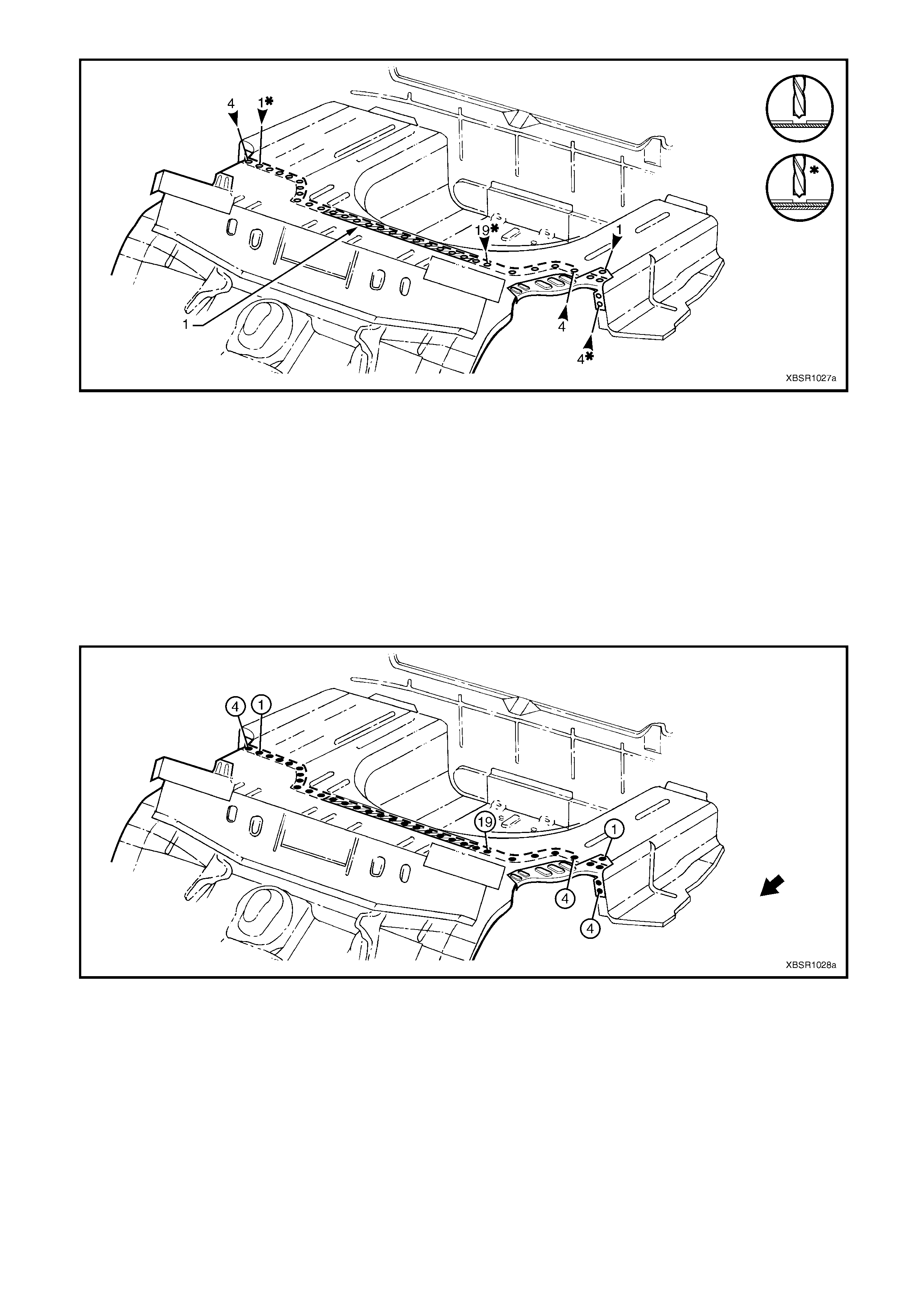
Figure 10A-79
REPLACE
NOTE 1: Spot welding is the preferred method for attaching of panels and should be used whenever possible.
Where the spot welding equipment will not access the required weld position, a plug weld should be performed.
NOTE 2: The s am e num ber and pos ition of s pot welds (or plug welds) s hould be used when replac ing the panel, as
was used during manufacture, in order to maintain the original structural strength of the vehicle.
1. As required, mark the new panel with drilling locations in preparation for plug welding. Drill holes as required.
2. Prepare all mating surfaces and treat with Weld Through Primer (Item 1) as required, refer to
5. BODY SEALING, ADHESIVES & DEADENERS in Section 3A.
3. Apply Structural Adhesive (Item 6), refer to 5. BODY SEALING, ADHESIVES & DEADENERS in Section 3A.
4. Clamp the new panel in position in the vehicle and plug weld to the rear floor rear. Refer to Figure 10A-80.
Figure 10A-80
4. Plug weld the rear floor panel assembly (2) to the
front floor panel assembly (1).
5. Plug weld the rear floor panel assembly to the
inner rocker panel (3) each side.
Figure 10A-81
6. Plug weld the rear floor panel assembly (1) to the
rear window panel assembly (2) and the rear seat
back panel extension assembly (3).
Figure 10A-82
7. Plug weld the park brake cable brack et to the rear
floor panel assembly.
8. Ins tall the r ear floor panel reinforc ement each side,
refer to 2.16 REAR FLOOR PANEL
REINFORCEMENT – REPLACE. Plug weld the
reinfor cem ents on the top s urf ace only, completing
the welds in the next step.
Figure 10A-83
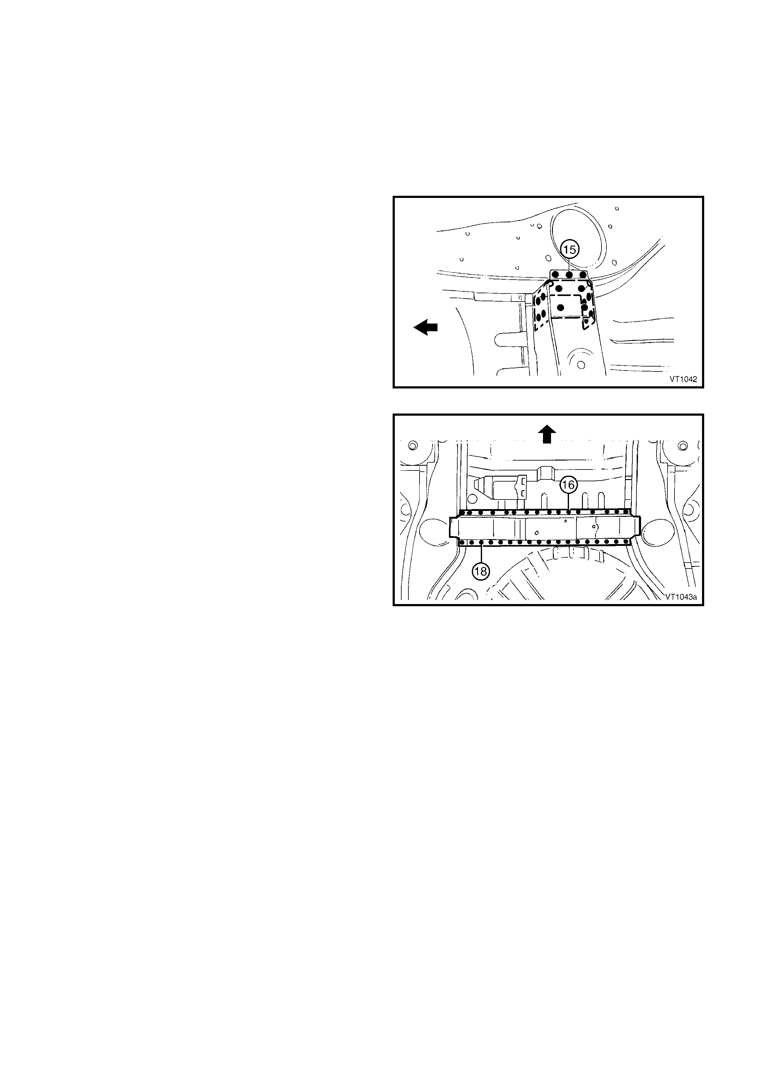
9. Spot or plug weld the rear floor panel assembly
and rear floor panel reinforcement to the rear
wheelhouse inner panel assembly on each of the
vehicle.
10. Plug weld the crossmember assembly No.2 to the
rear floor panel assembly, refer to
2.10 CROSSMEMBER ASSEMBLY NO. 2 –
REPLACE.
11. Plug weld each rear side rail assembly to the rear
floor panel assembly, refer to 2.14 REAR SIDE
RAIL ASSEMBLY – REPLACE.
12. Replace any other rem oved panels as des c ribed in
the appropriate Section of this Supplement.
13. Refinish and paint panels and other components
as required. Refer to Section 3, 1.3 PAINT
REFINISHING.
14. Apply Joint Sealer (Item 3) as required. Refer to
5. BODY SEALING, ADHESIVES & DEADENERS
in Section 3A.
15. Apply Cavity Wax (Item 8) as r equired to the inside
of any box sections or areas inaccessible to paint,
refer to 6. CAVITY WAX in Section 3A.
16. Apply deadener panels to the rear compartment
floor panel, refer to 5.6 DEADENER PANELS &
INSULATORS in Section 3A.
17. Apply Spray-on Deadener (Item 7) where
applicable, refer to 5. BODY SEALING,
ADHESIVES & DEADENERS in Section 3A.
18. Install the remaining components as described in
the appropriate Section of the MY 2003 VY & V2
Series II Service Information.
Figure 10A-84
2.16 RE AR FLOOR PANEL REINFORCEMENT – REP LACE
LEFT-HAND SIDE
REMOVE
The left-hand rear floor panel reinforcement is spot
welded to the rear floor panel assembly, rear
wheelhouse panel assembly, rear compartment floor
panel assembly outer extension and rear side rail
assembly.
As required spot cut the welds and remove the
reinforcement.
REPLACE
NOTE 1: Spot welding is the preferred method for
attaching of panels and should be used whenever
possible. W here the spot welding equipment available
to the repairer will not access the required weld
position, a plug weld should be performed.
NOTE 2: T he sam e num ber and position of spot welds
(or plug welds) should be used when replacing the
panel, as was used during manufacture, in order to
maintain the original structural strength of the vehicle.
1. As required, mark the new panel with drilling
locations in prepar ation f or plug welding. Drill holes
as required.
2. Prepare all mating surfaces and treat with Weld
Through Primer (Item 1) as required, refer to
5. BODY SEALING, ADHESIVES & DEADENERS
in Section 3A.
3. Spot or plug weld the rear floor panel
reinfor c ement to the vehicle, ensur ing it is c orr ec tly
located and welded through the correct panels.
Figure 10A-85
RIGHT-HAND SIDE
REMOVE
The right-hand rear floor panel reinforcement is spot
welded to the rear floor panel assembly, rear
wheelhouse panel assembly and rear side rail
assembly.
As required spot cut the welds and remove the
reinforcement.
REPLACE
NOTE 1: Spot welding is the preferred method for
attaching of panels and should be used whenever
possible. W here the spot welding equipment available
to the repairer will not access the required weld
position, a plug weld should be performed.
NOTE 2: T he sam e num ber and position of spot welds
(or plug welds) should be used when replacing the
panel, as was used during manufacture, in order to
maintain the original structural strength of the vehicle.
1. As required, mark the new panel with drilling
locations in prepar ation f or plug welding. Drill holes
as required.
2. Prepare all mating surfaces and treat with Weld
Through Primer (Item 1) as required, refer to
5. BODY SEALING, ADHESIVES & DEADENERS
in Section 3A.
3. Spot or plug weld the rear floor panel
reinfor c ement to the vehicle, ensur ing it is c orr ec tly
located and welded through the correct panels.
Figure 10A-86