
SECTION 10B – BODY REAR – WAGON
IMPORTANT
Before perfo rming any Service O perat ion or o th er pro cedu re describ ed in th is Section, refer to Section
00 CAUTIONS AND NOTES and Section 2 PRECAUTIONS in this Supplement for correct workshop
practices with regard to safety and/or property damage.
CAUTION
The Structure of the M Y 2003 VY & V2 Series II body shell has been developed using complex design
and development techniques. In addition to meeting all required standards, the v ehicle body is also a
critical part of the overall safety systems. It is therefore imperative the repair procedures described
here are adhered to during all vehicle body repairs.
1. GENERAL DESCRIPTION
1.1 BODY REAR COMPONENTS
2. SERVICE OPERATIONS
2.1 REAR END LOWER PANEL – REPLACE
REMOVE
REPLACE
2.2 REAR END PANEL ASSEMBLY –
REPLACE
REMOVE
REPLACE
2.3 REAR END PANEL EXTENSION –
REPLACE
REMOVE
REPLACE
2.4 FUEL TANK SUPPORT
REINFORCEMENT – REPLACE
REMOVE
REPLACE
2.5 REAR COMPARTMENT FLOOR PANEL
OUTER EXTENSION – REPLACE
REMOVE
REPLACE
2.6 REAR COMPARTMENT FLOOR PANEL
ASSEMBLY – REPLACE
REMOVE
REPLACE
2.7 REAR WHEELHOUSE INNER PANEL
ASSEMBLY – REPLACE
REMOVE
REPLACE
2.8 REAR FLOOR PANEL ASSEMBLY –
REPLACE
REMOVE
REPLACE
2.9 REAR BUMPER IMPACT BAR BRACE
ASSEMBLY – REPLACE
REMOVE
REPLACE
2.10 CROSSMEMBER ASSEMBLY NO. 2 –
REPLACE
REMOVE
REPLACE
2.11 REAR TIE DOWN ASSEMBLY – REPLACE
REMOVE
REPLACE
2.12 REAR FLOOR PANEL OUTER EXTENSION –
REPLACE
REMOVE
REPLACE
2.13 REAR SIDE RAIL ASSEMBLY – REPLACE
REMOVE
REPLACE
1. GENERAL DESCRI PTI O N
This Section describes replacem ent procedures for the rear section com ponents of the MY 2003 VY Series Wagon
body structure. Removal of bolt-on and mechanical components is not covered. Reference must be made to the
appropriate Sections in the MY 2003 VY & V2 Series II Service Information.
When repairing the rear of the vehicle, care must be taken to ensure the structure is returned to its original
production configuration.
NOTE: It is imperative that the correct body adhesives, sealers, deadeners and cavity waxes are used when
repairing the body structure of MY 2003 VY Series W agon vehicles. Refer to 5. BODY SEALING, ADHESIVES &
DEADENERS and 6. CAVITY WAX in Section 3B for details of the correct materials and their commercially
available equivalents.
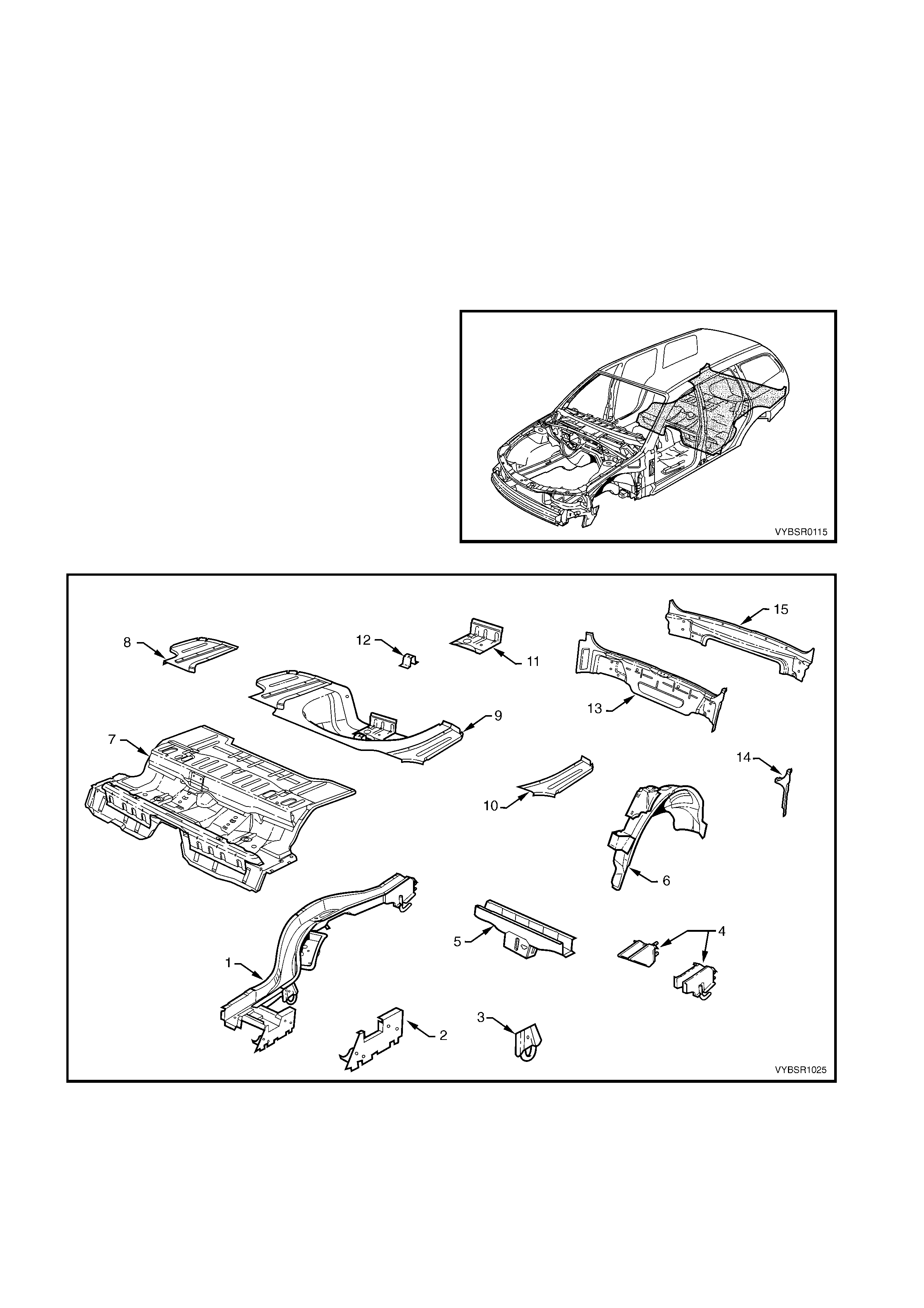
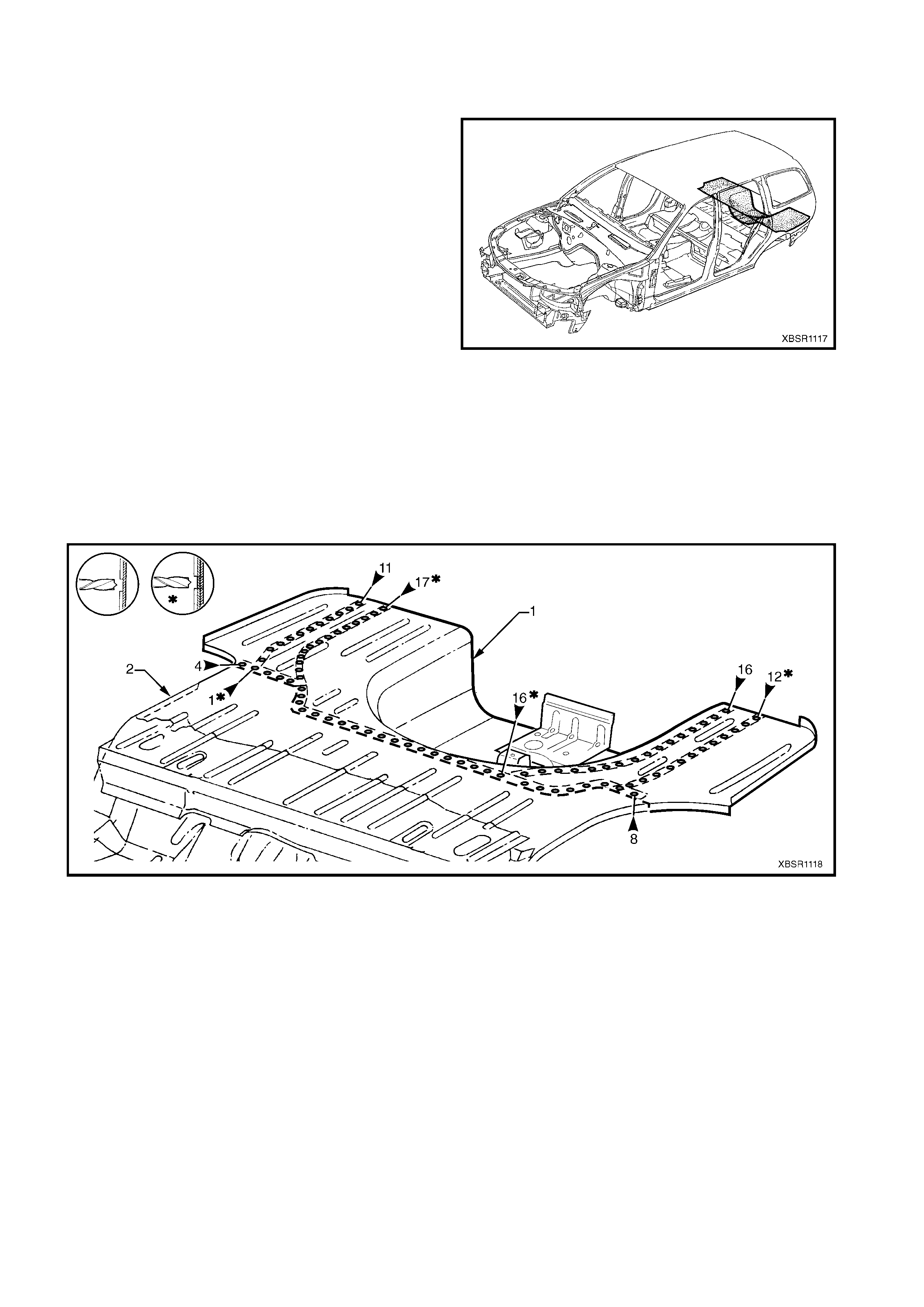
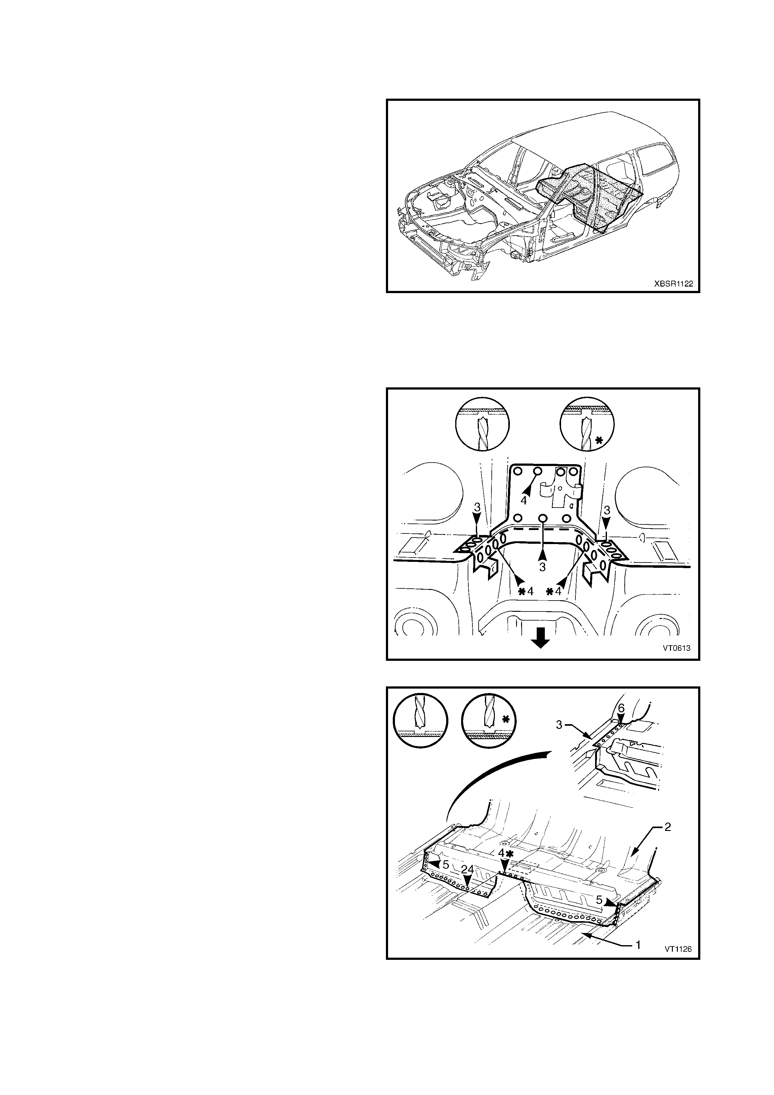
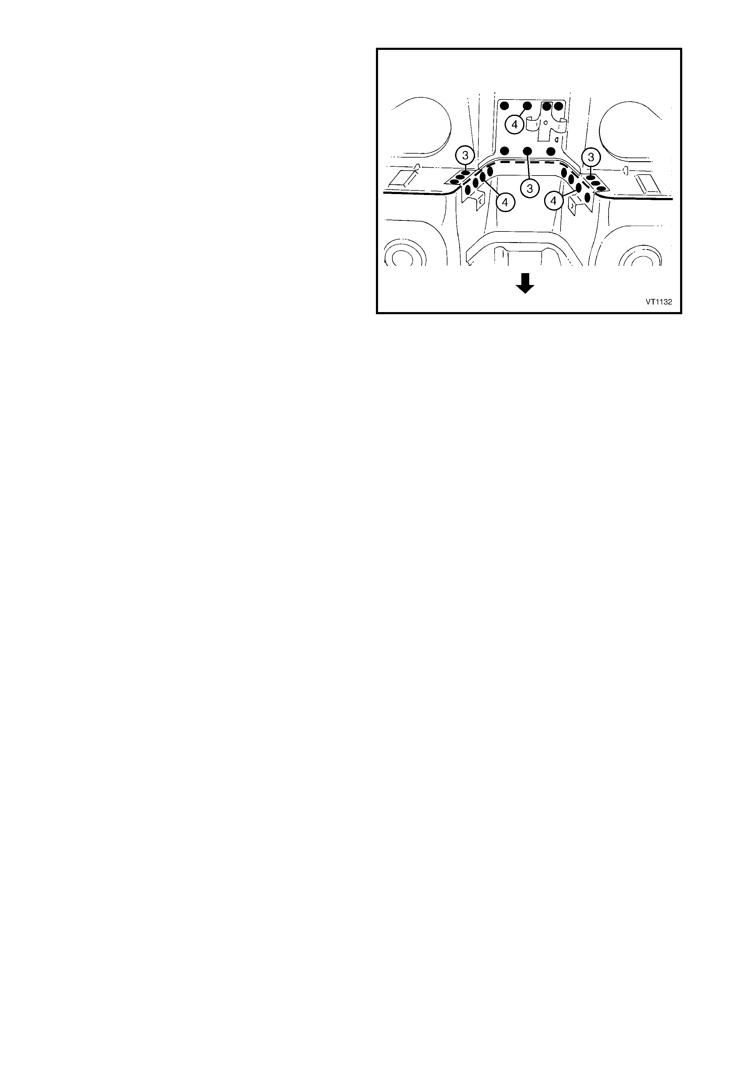
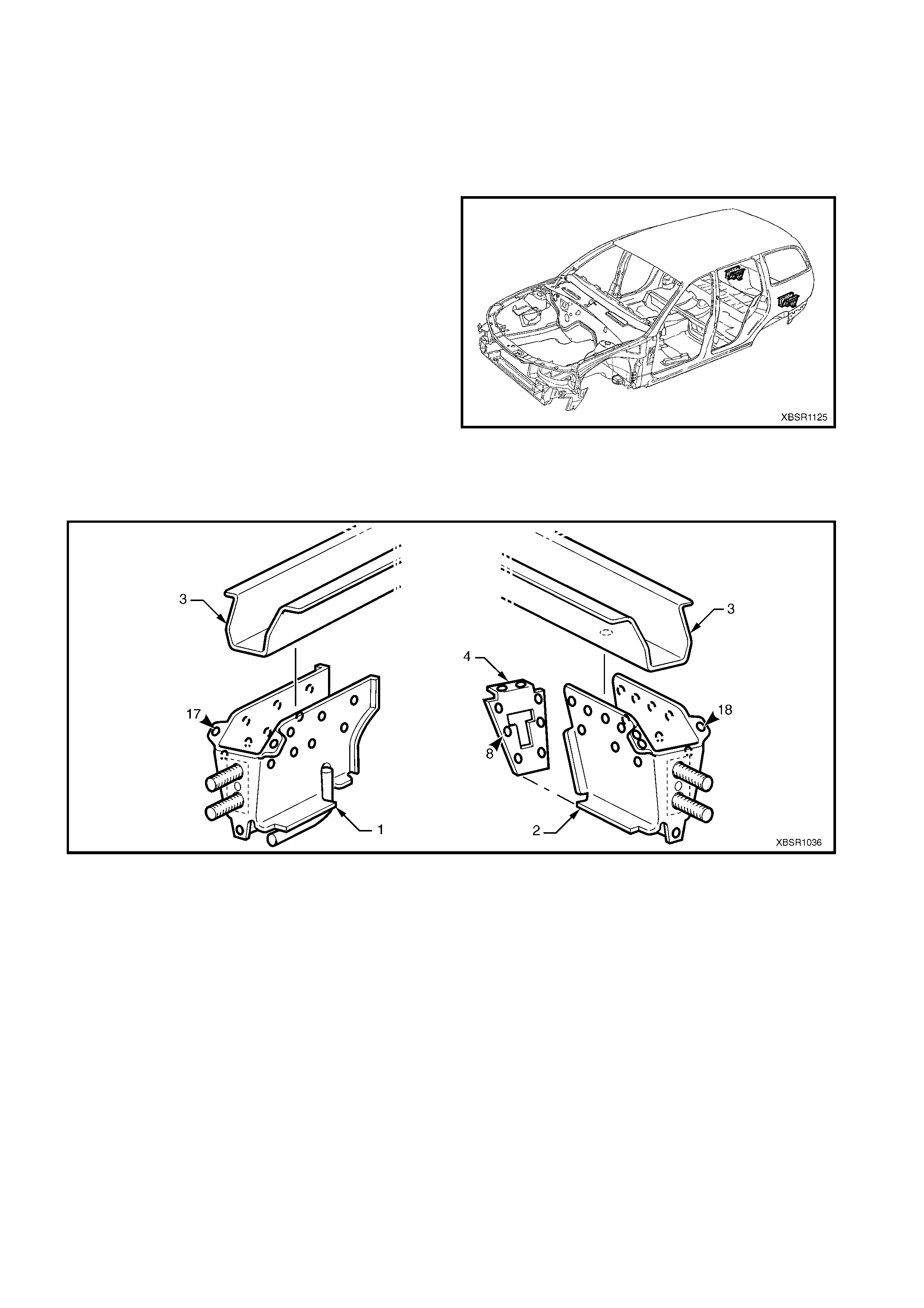
1.1 BODY REAR COMPONENTS
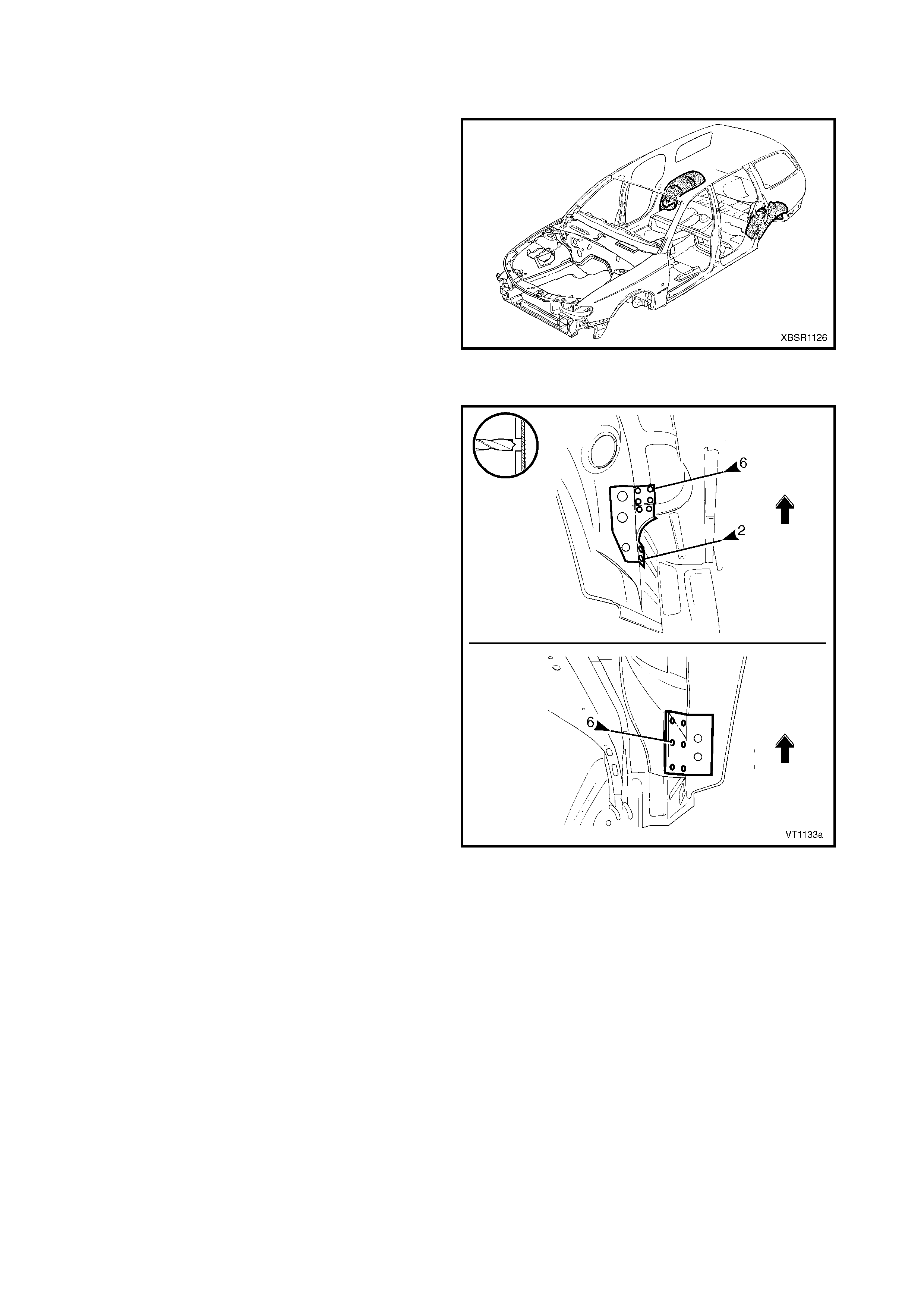
The shaded components in Figure 10B-1 are those
dealt with in this Section.
The components and assemblies shown in Figure
10B-2 are the parts serviced for MY 2003 VY Series
Wagon vehicles which form the basis of the repair
procedures in this Section. For a detailed view of the
body components, refer to Section 3B BODY
CONSTRUCTION – WAGON.
NOTE: Always refer to your Authorised Retailer for
spare parts availability configurations.
Figure 10B-1
Figure 10B-2

Legend (Figure 10B-2)
1. Rear Side Rail Assembly
2. Rear Floor Panel Outer Extension
3. Rear Tie Down Hook Assembly
4. Rear Bumper Impact Bar Brace Assembly
5. Crossmember Assembly No. 2
6. Rear Wheelhouse Inner Panel Assembly
7. Rear Floor Panel Assembly
8. Rear Compartment Floor Panel Outer Extension, Left-
Hand
9. Rear Compartment Floor Panel Assembly
10. Rear Compartment Floor Panel Outer Extension, Right-
Hand
11. Fuel Tank Support Reinforcement Assembly
12. Spare Wheel Anchor Plate Assembly
13. Rear End Panel Assembly
14. Rear End Panel Extension
15. Rear End Lower Panel
NOTE 1: Rear side rail assembly includes parts No. 2, 3 & 4.
NOTE 2: Rear compartment floor panel assembly includes parts No. 8, 10, 11 & 12.
NOTE 3: Rear end panel assembly incudes part No. 14.
2. SERVICE OPERATIONS
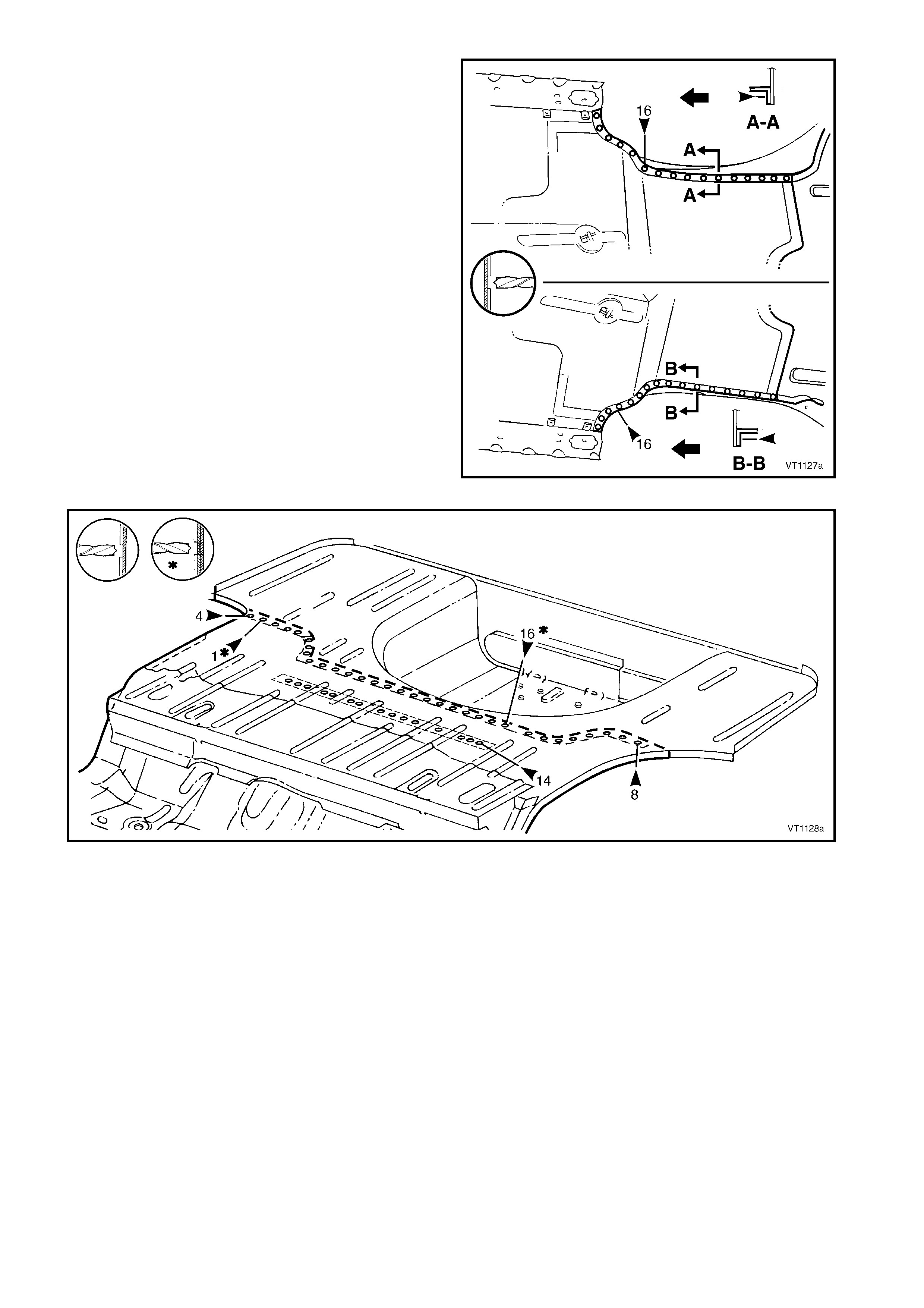
2.1 REAR END LOWER PANEL – REPLACE
NOTE: If the rear end panel (inner) is also to be
replaced, rem ove the rear end panels as an assembly.
Refer to 2.2 REAR END PANEL – REPLACE.
REMOVE
CAUTION: To avoid the possibility of fire, take
particular care when cutting or welding at the rear
of the vehicle. Remove the fuel tank and plug all
fuel lines.
1. Remove the adjacent bolt-on panels and
components as described in the appropriate
Section of the MY 2003 VY & V2 Series II Service
Information.
2. Remove the rear bumper impact bar assembly,
refer to 2. BUMPER IM PACT BAR ASSEMBLIES
in Section 3.
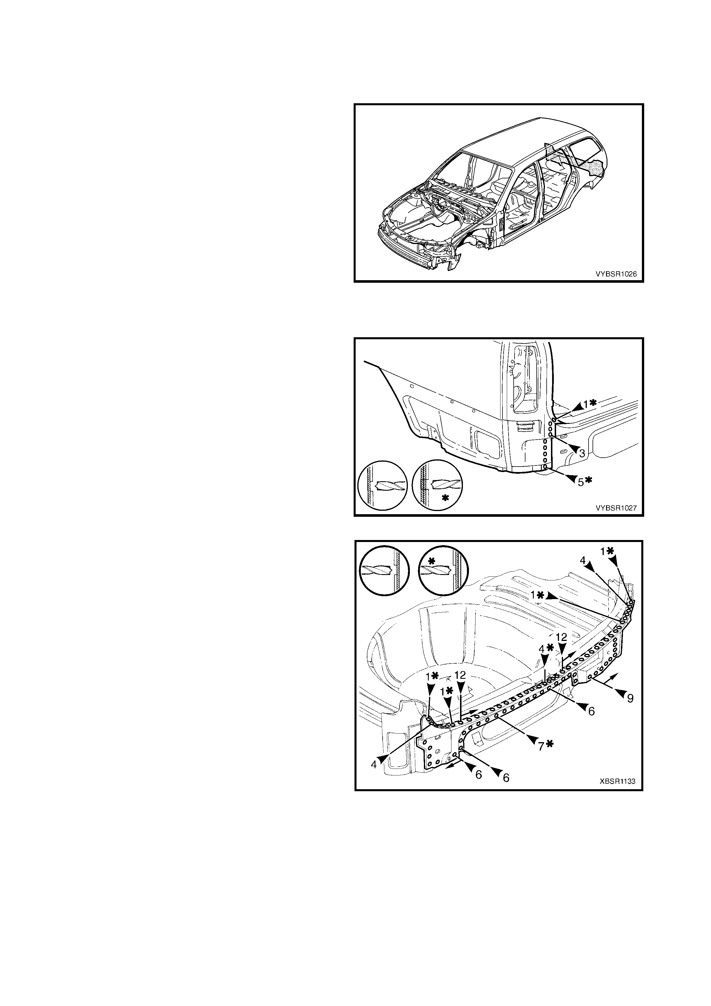
Figure 10B-3
3. If the quarter panel extensions are not being
rem oved, spot cut the welds attaching the rear end
lower panel. If they are to be removed, refer to
2.2 QUARTER PANEL EXTENSION – REPLACE
in Section 7B.
NOTE: The rear end lower panel is fitted under each
quarter panel extension.
Figure 10B-4
4. Spot cut the welds attaching the rear end lower
panel to the rear end panel assembly.
5. Remove the rear end lower panel.
Figure 10B-5
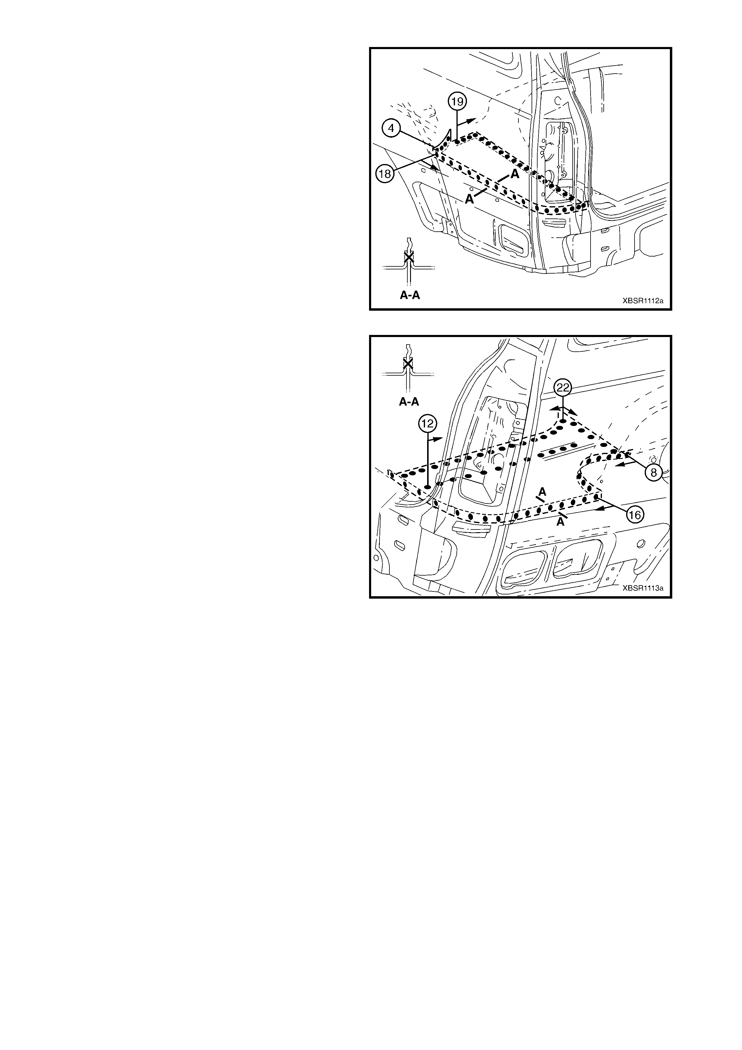
REPLACE
NOTE 1: Spot welding is the preferred method for attaching of panels and should be used whenever possible.
Where the spot welding equipment will not access the required weld position, a plug weld should be performed.
NOTE 2: The s ame number and pos ition of s pot welds (or plug welds) s hould be used when replac ing the panel,
as was used during manufacture, in order to maintain the original structural strength of the vehicle.
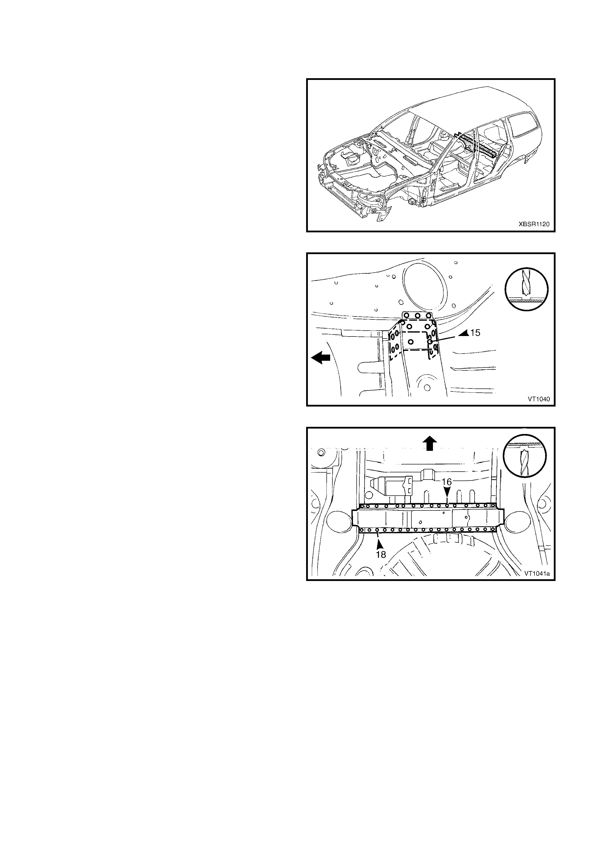
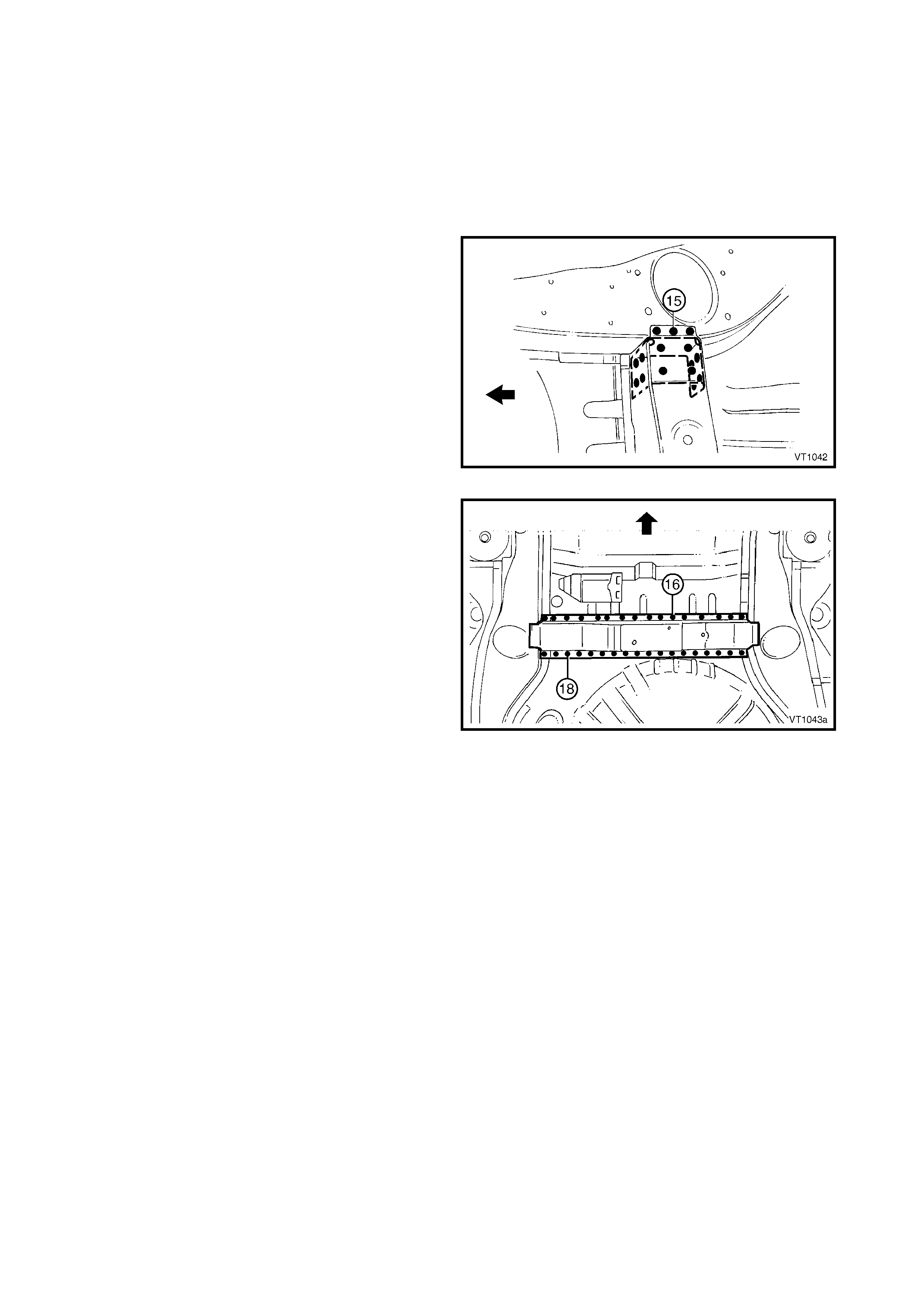
1. As required, mark the new panel with drilling locations in preparation for plug welding. Drill holes as required.
2. Prepare all mating surfaces and treat with Weld Through Primer (Item 1) as required, refer to
5. BODY SEALING, ADHESIVES & DEADENERS in Section 3B.
3. Clamp the rear end lower panel in position and
spot or plug weld to the rear end panel assembly.
Figure 10B-6
4. As required, weld the quarter panel extension to
the rear end panel ass em bly or replace the quarter
panel extension, refer to 2.2 QUARTER PANEL
EXTENSION – REPLA CE in Section 7B.
5. Refinish and paint panels and other components
as required. Refer to Section 3, 1.3 PAINT
REFINISHING.
6. Apply Joint Sealer (Item 3) as required. Refer to
5. BODY SEALING, ADHESIVES & DEADENERS
in Section 3B.
7. Apply Cavity Wax (Item 8) as r equired to the inside
of any box sections or areas inaccessible to paint,
refer to 6. CAVITY WAX in Section 3B.
8. Install the rear bum per impact bar assembly, refer
to 2. BUMPER IMPACT BAR ASSEMBLIES in
Section 3.
9. Install the remaining components as described in
the appropriate Section of the MY 2003 VY & V2
Series II Service Information.
Figure 10B-7
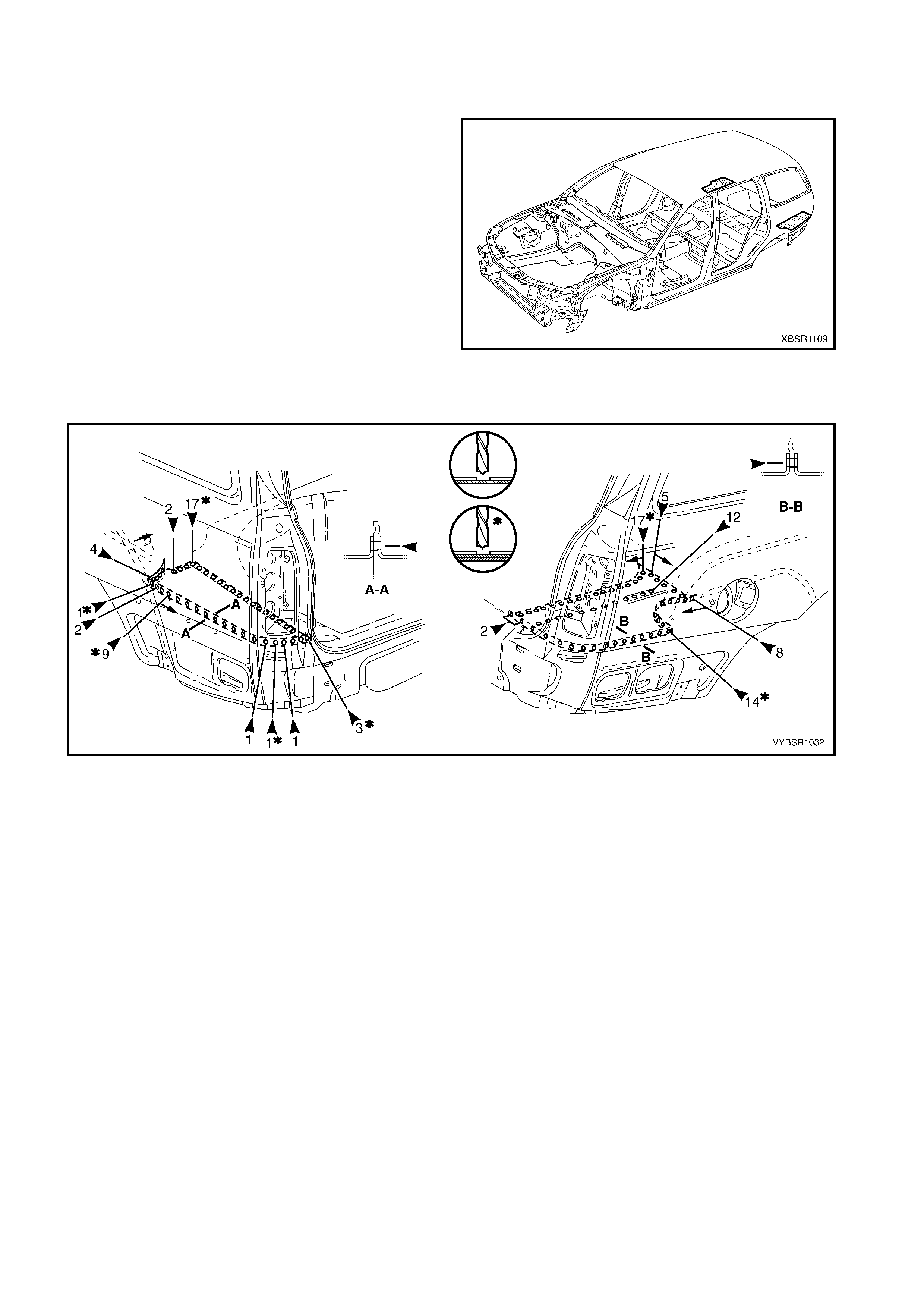
2.2 REAR END PANEL ASSEMBLY – REPLACE
NOTE: This procedure describes the removal of the
rear end lower panel and rear end panel as an
assembly. As the panels are supplied individually, this
procedure contains the replacement of the rear end
panel only. Reference should be then made to
2.1 REAR END LOWER PANEL – REPLACE for the
relevant replacement procedures of the remaining
panel.
REMOVE
CAUTION: To avoid the possibility of fire, take
particular care when cutting or welding at the rear
of the vehicle. Remove the fuel tank and plug all
fuel lines.
1. Remove the adjacent bolt-on panels and
components as described in the appropriate
Section of the MY 2003 VY & V2 Series II Service
Information.
2. Remove the rear bumper impact bar assembly,
refer to 2. BUMPER IM PACT BAR ASSEMBLIES
in Section 3.
Figure 10B-8
3. Either:
A. Remove the quarter panel extensions, refer to 2.2 QUARTER PANEL EXTENSION – REPLACE in
Section 7B and, spot cut the welds attaching the rear end panel extensions to the vehicle, refer to
2.3 REAR END PANEL EXTENSION – REPLACE.
B. To avoid removal of the quarter panel extensions:
Spot cut the welds attaching the rear end lower panel to the quarter panel extension, refer to
2.1 REAR END LOWER PANEL – REPLACE and, spot cut the welds attaching the rear end panel to
rear end panel extension each side and leave the rear end panel extensions in place.
Figure 10B-9
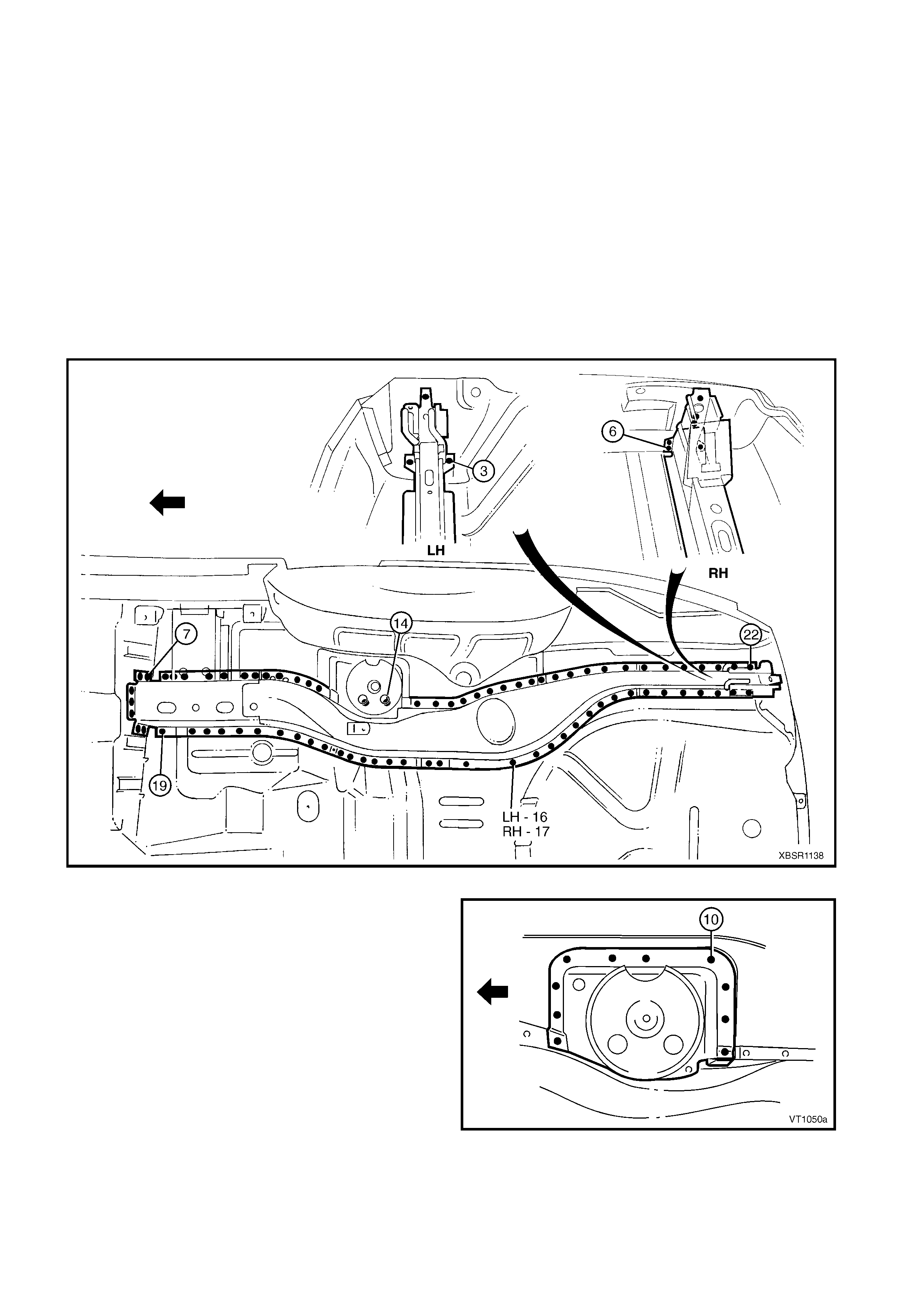
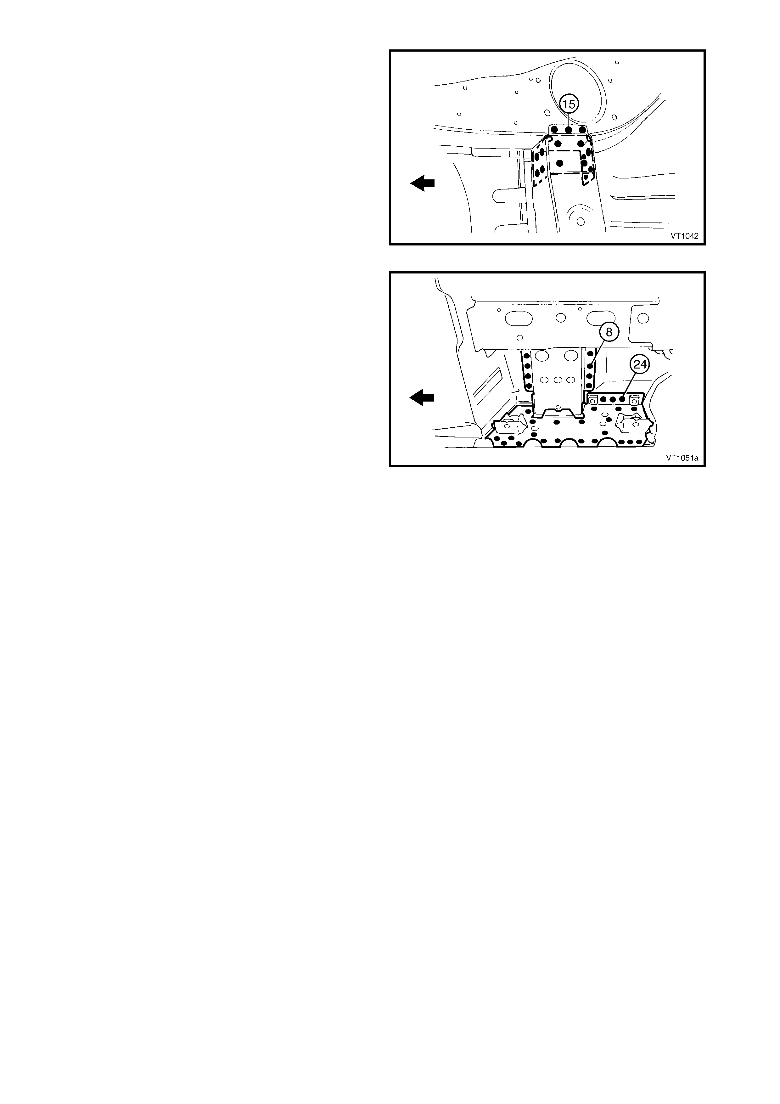
4. Spot cut the welds attaching the fuel tank support
reinforcement to the rear end panel assembly.
NOTE: As an alternative, the fuel tank support
reinforcement can be removed from the
rear compartment floor panel assembly, refer to
2.4 FUEL TANK SUPPORT REINFORCEMENT –
REPLACE.
5. Spot cut the welds attaching the rear end panel
assembly to the rear compartment floor panel
assembly, refer to Figure 10B-11.
Figure 10B-10
Figure 10B-11
6. Spot cut the welds attaching the rear side rail
assemblies to the rear end panel assembly. Note
that the left-hand side is different to the right-hand
side.
7. Remove the panel from the vehicle, then repair
any damage to adjacent parts.
8. Check and rectify the alignment of the body
shell. Refer to 3 BODY DIMENSIONS in this
Supplement.
Figure 10B-12
REPLACE
NOTE 1: Spot welding is the preferred method for attaching of panels and should be used whenever possible.
Where the spot welding equipment will not access the required weld position, a plug weld should be performed.
NOTE 2: The s ame number and pos ition of s pot welds (or plug welds) s hould be used when replac ing the panel,
as was used during manufacture, in order to maintain the original structural strength of the vehicle.
1. If the rear end panel was removed from the rear end panel extensions, spot cut the welds and rem ove the
extensions on the new panel.
2. Prepare all mating surfaces and treat with Weld Through Primer (Item 1) as required, refer to
5. BODY SEALING, ADHESIVES & DEADENERS in Section 3B.
3. If the rear end panel extens ions were left attached to the vehicle, spot cut the welds attaching the extensions
to the rear end panel on the replacement section.
4. Install the rear end panel assembly in position and spot or plug weld to the rear compartment floor panel
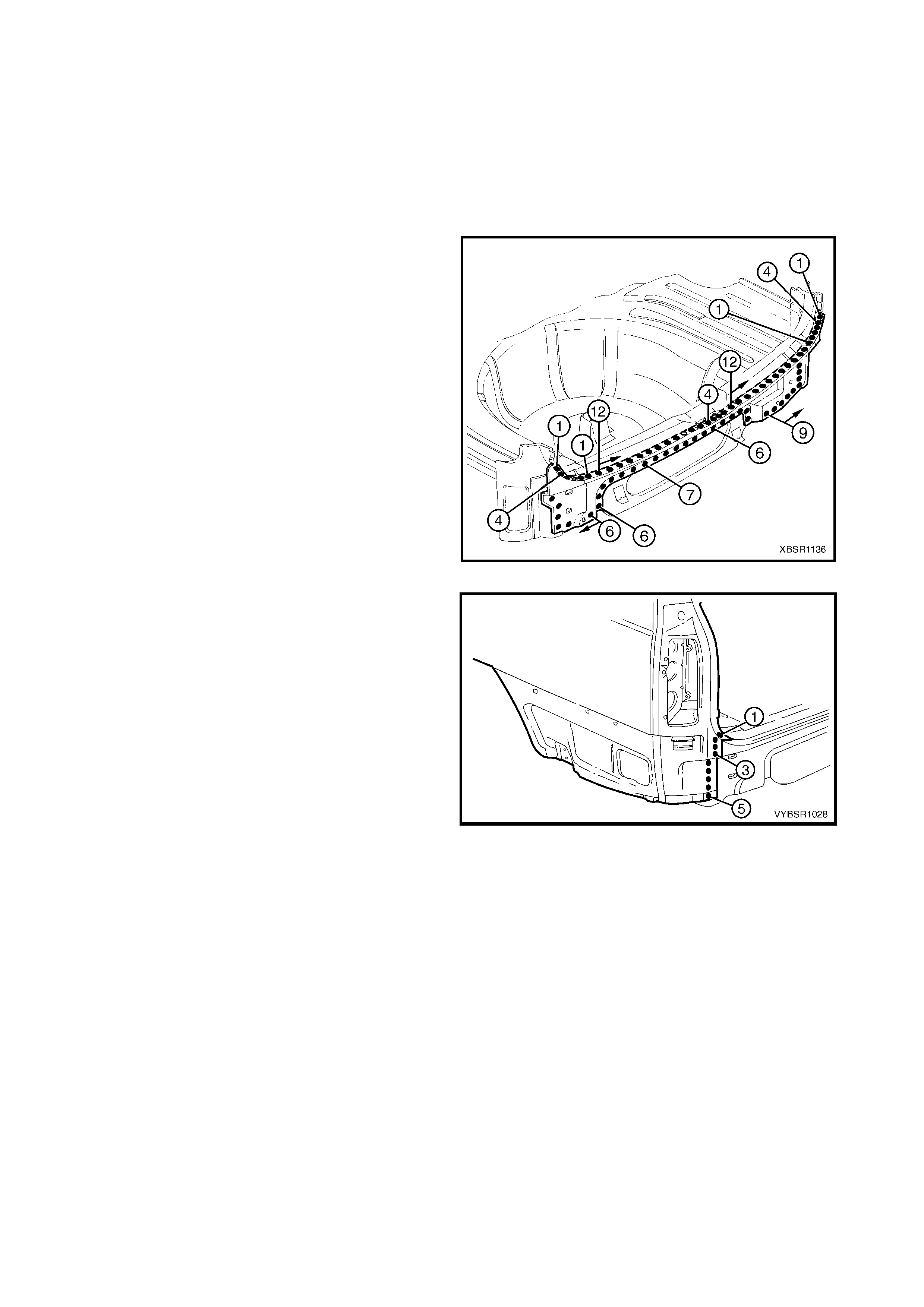
assembly, refer to Figure 10B-13.
Figure 10B-13
5. Spot or plug weld the rear side rail assemblies to
the rear end panel assembly. Note that the left-
hand side is different to the right-hand side.
Figure 10B-14
6. Spot or plug weld the fuel tank support
reinforcement to the rear end panel assembly or
replace the fuel tank support reinforcement, refer
to 2.4 FUEL TANK SUPPORT REINFORCEMENT
– REPLACE.
NOTE: Complete the top row of welds when welding
the rear end lower panel.
7. Depending on removal method either:
A. Spot or plug weld the rear end panel
extensions to the vehicle, refer to
2.3 REAR END PANEL EXTENSION –
REPLACE, or
Figure 10B-15
B. If the quarter panel extensions were left
attached to the vehicle, spot or plug weld the
rear end panel to rear end panel extension
each side.
8. In the areas where the rear end lower panel will fit,
grind the welds and prime any bare metal.
9. Ins tall the rear end lower panel, refer to 2.1 REAR
END LOWER PANEL – REPLACE.
10. Refinish and paint panels and other components
as required. Refer to Section 3, 1.3 PAINT
REFINISHING.
11. Apply Joint Sealer (Item 3) as required. Refer to
5. BODY SEALING, ADHESIVES & DEADENERS
in Section 3B.
12. Apply Cavity Wax (Item 8) as requir ed to the inside
of any box sections or areas inaccessible to paint,
refer to 6. CAVITY WAX in Section 3B.
13. Install the rear bum per impact bar assembly, refer
to 2. BUMPER IMPACT BAR ASSEMBLIES in
Section 3.
14. Install the remaining components as described in
the appropriate Section of the MY 2003 VY & V2
Series II Service Information.
Figure 10B-16
2.3 REAR END PANEL EXTENSION – REPLACE
REMOVE
CAUTION: To avoid the possibility of fire, take
particular care when cutting or welding at the rear
of the vehicle. Remove the fuel tank and plug all
fuel lines.
1. Remove the adjacent bolt-on panels and
components as described in the appropriate
Section of the MY 2003 VY & V2 Series II Service
Information.
2. Remove the rear bumper impact bar assembly,
refer to 2. BUMPER IM PACT BAR ASSEMBLIES
in Section 3.
3. Remove the quarter panel extension, refer to
2.2 QUARTER PANEL EXTENSION – REPLACE
in Section 7B.
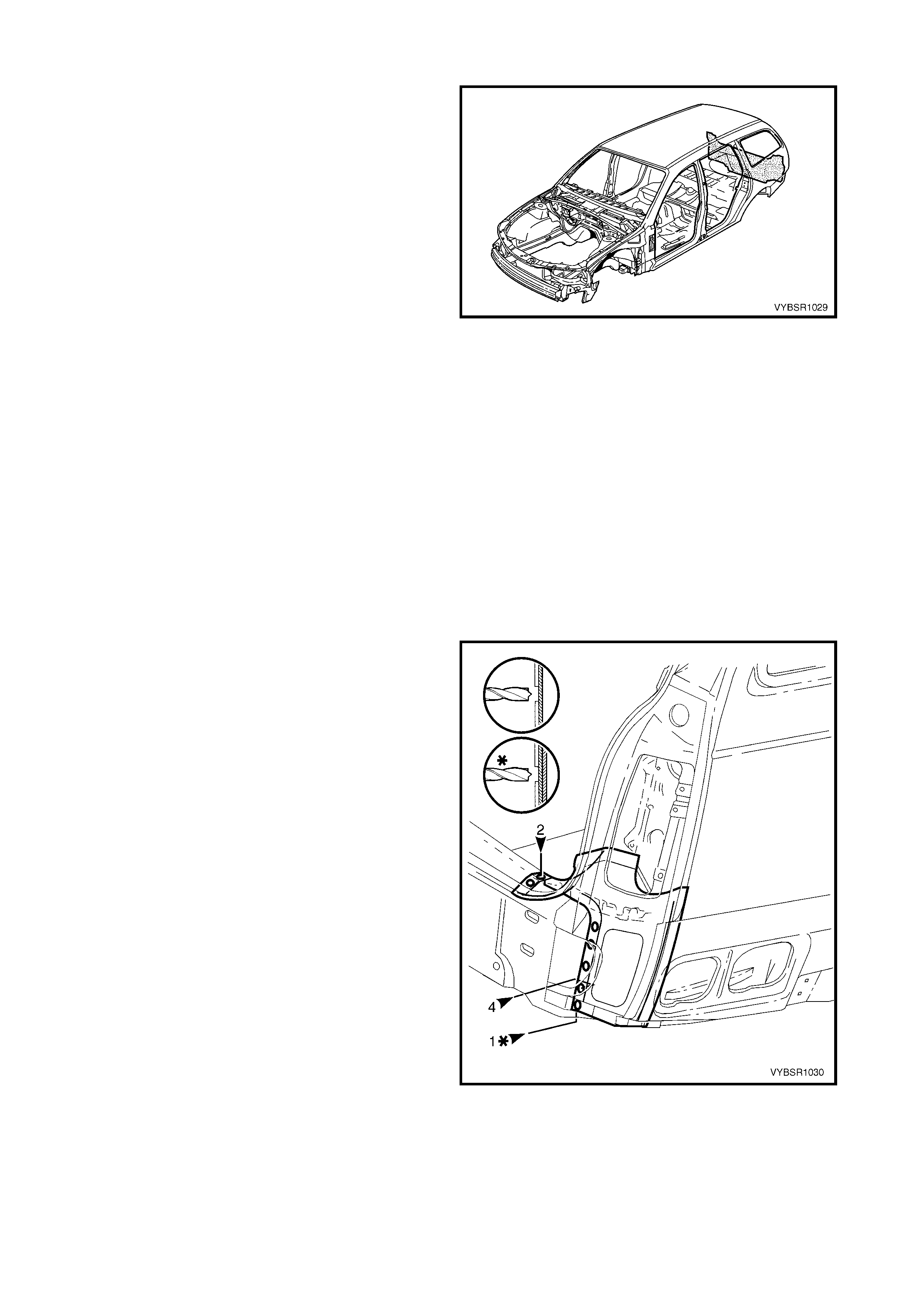
Figure 10B-17
4. From underneath the vehicle, spot cut the welds
attaching the rear end panel extension to the
quarter panel inner assembly and rear end panel
assembly.
5. Spot cut the welds attaching the rear end panel
extension to the quarter panel inner assembly, r ear
end panel assembly and rear compartment floor
panel assembly, refer to Figure 10B-19.
6. Remove the extension from the vehicle and then
repair any damage to adjacent parts.
Figure 10B-18
Figure 10B-19
REPLACE
NOTE 1: Spot welding is the preferred method for attaching of panels and should be used whenever possible.
Where the spot welding equipment will not access the required weld position, a plug weld should be performed.
NOTE 2: The s ame number and pos ition of s pot welds (or plug welds) s hould be used when replac ing the panel,
as was used during manufacture, in order to maintain the original structural strength of the vehicle.
1. As required, mark the new panel with drilling locations in preparation for plug welding. Drill holes as required.
2. Prepare all mating surfaces and treat with Weld Through Primer (Item 1) as required, refer to
5. BODY SEALING, ADHESIVES & DEADENERS in Section 3B.
3. Clamp the rear end panel extension in position on
the vehicle and spot or plug weld to the quarter
panel inner assembly, rear end panel assembly
and rear compartment floor panel assembly.
Figure 10B-20
4. F rom under neath the vehicle, plug or spot weld the
rear end panel extens ion to the quarter panel inner
assembly and rear end panel assembly.
5. Replace the quarter panel extension, refer to
2.2 QUARTER PANEL EXTENSION – REPLACE
in Section 7B.
6. Refinish and paint panels and other components
as required. Refer to Section 3, 1.3 PAINT
REFINISHING.
7. Apply Joint Sealer (Item 3) as required. Refer to
5. BODY SEALING, ADHESIVES & DEADENERS
in Section 3B.
8. Apply Cavity Wax (Item 8) as requir ed to the inside
of any box sections or areas inaccessible to paint,
refer to 6. CAVITY WAX in Section 3B.
9. Install the rear bum per impact bar assembly, refer
to 2. BUMPER IMPACT BAR ASSEMBLIES in
Section 3.
10. Install the remaining components as described in
the appropriate Section of the MY 2003 VY & V2
Series II Service Information.
Figure 10B-21
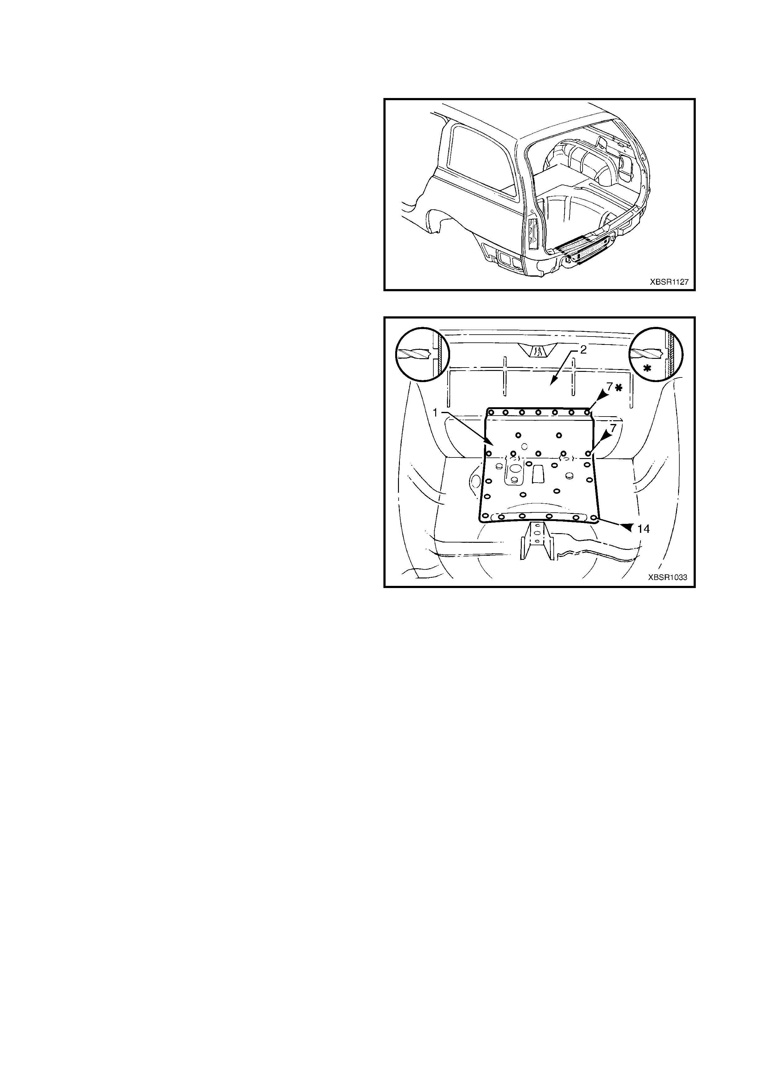
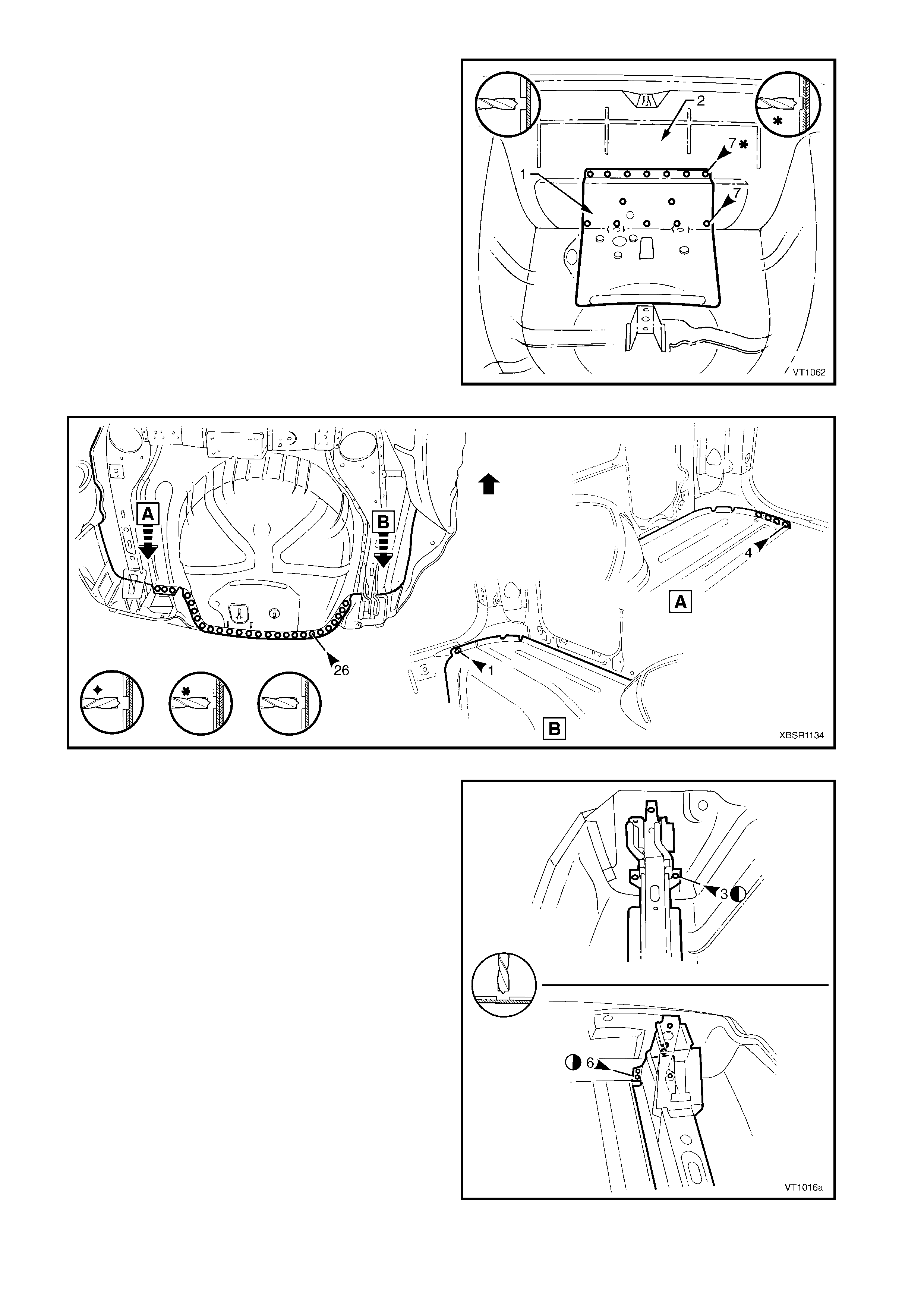
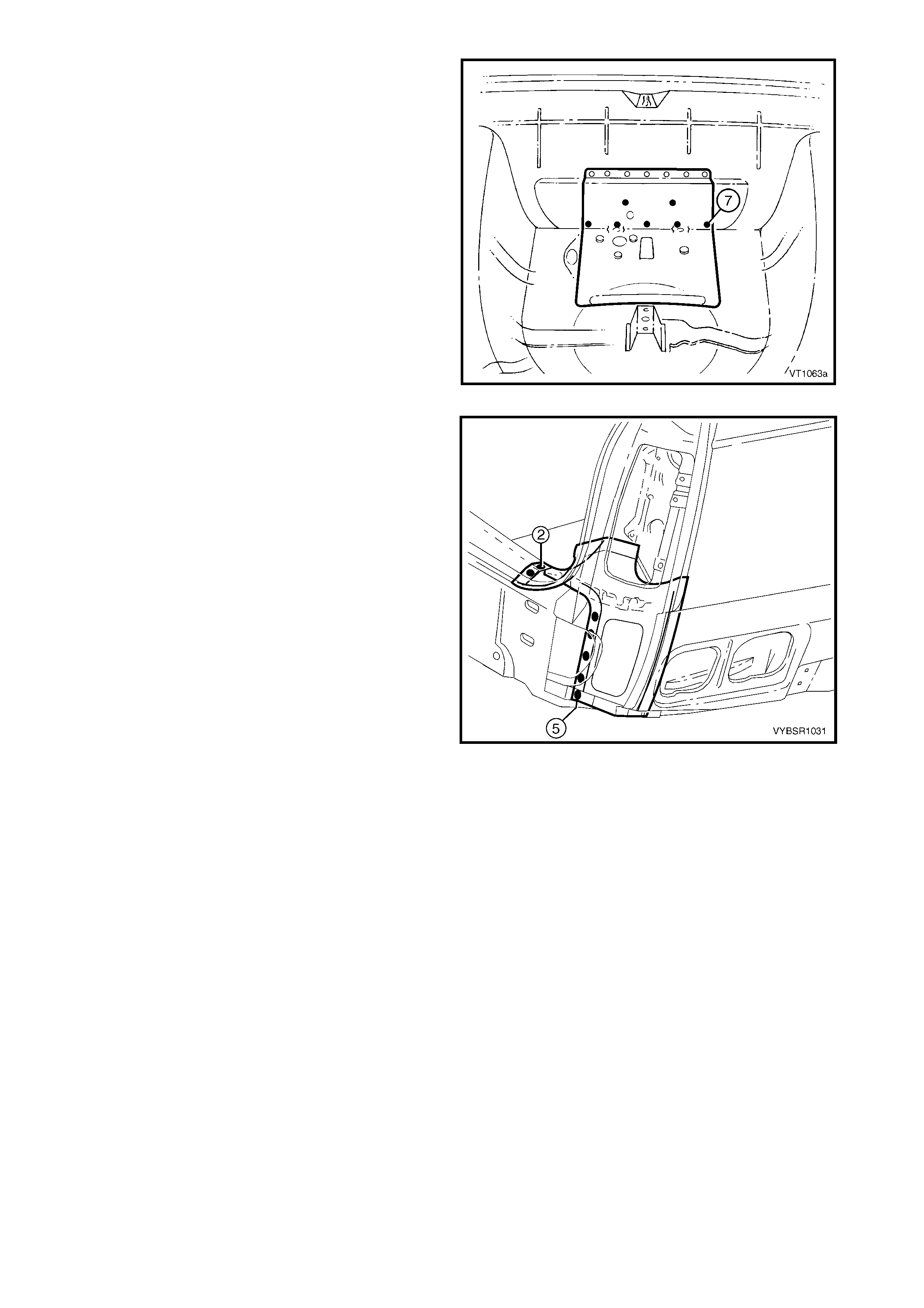
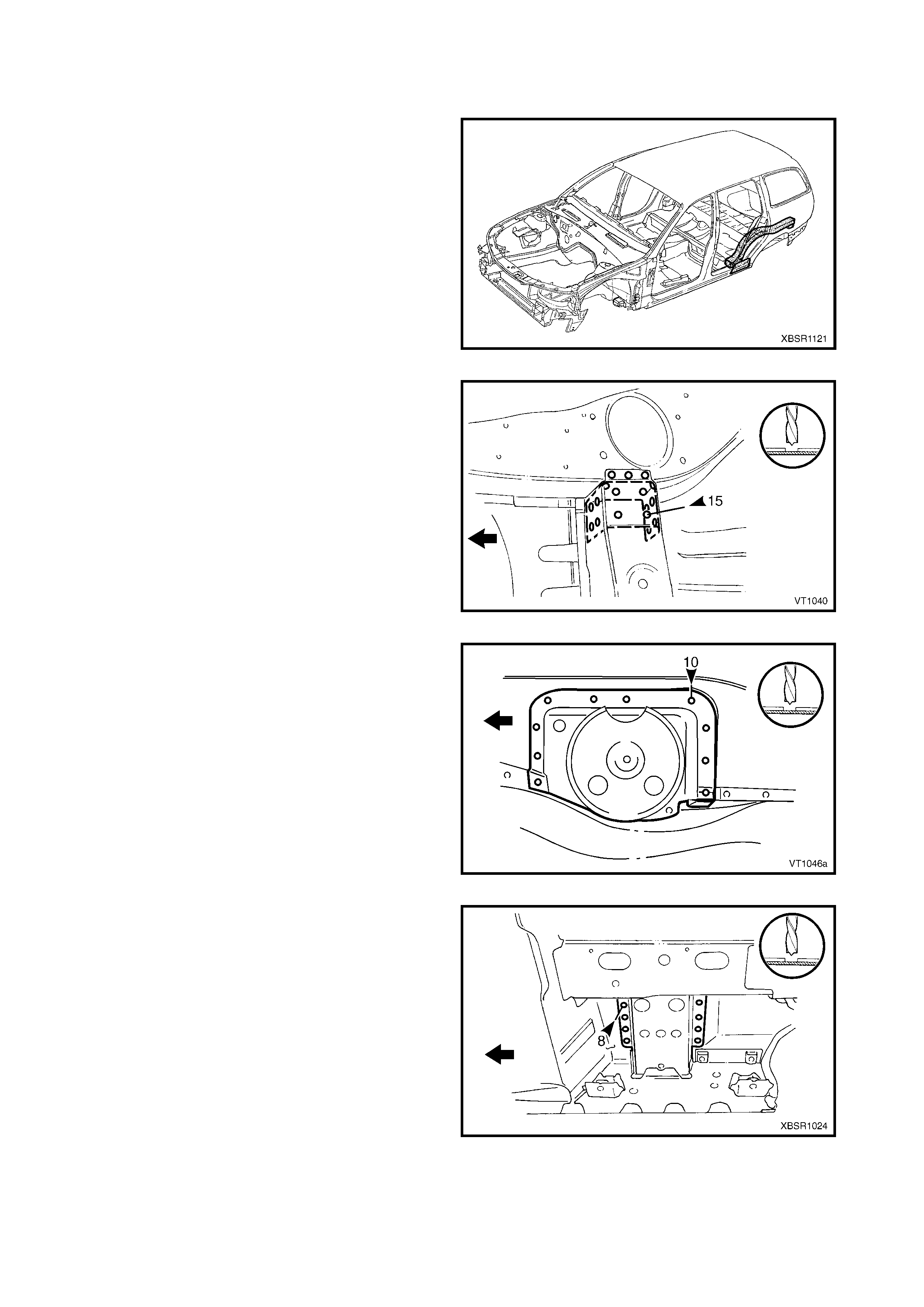
2.4 FUEL TANK SUPPORT REINFORCEMENT ASSEMBLY – REPLACE
REMOVE
CAUTION: To avoid the possibility of fire, take
particular care when cutting or welding at the rear
of the vehicle. Remove the fuel tank and plug all
fuel lines.
1. Remove the adjacent bolt-on panels and
components as described in the appropriate
Section of the MY 2003 VY & V2 Series II Service
Information.
2. Rem ove the floor deadener panels and joint s ealer
from around the fuel tank support reinforcement
assembly as required.
Figure 10B-22
3. Spot cut the 14 welds attaching the reinforcement
to the rear end panel assembly.
4. Spot cut the 14 welds attaching the reinforcement
to the rear compartment floor panel assembly.
5. Remove the fuel tank support reinforcement
assem bly and then repair any damage to adjacent
parts as required.
Figure 10B-23
REPLACE
NOTE 1: Spot welding is the preferred method for attaching of panels and should be used whenever possible.
Where the spot welding equipment available will not access the required weld position, a plug weld should be
performed.
NOTE 2: The s ame number and pos ition of s pot welds (or plug welds) s hould be used when replac ing the panel,
as was used during manufacture, in order to maintain the original structural strength of the vehicle.
1. As required, mark the new panel with drilling locations in preparation for plug welding. Drill holes as required.
2. Prepare all mating surfaces and treat with Weld Through Primer (Item 1) as required, refer to
5. BODY SEALING, ADHESIVES & DEADENERS in Section 3B.
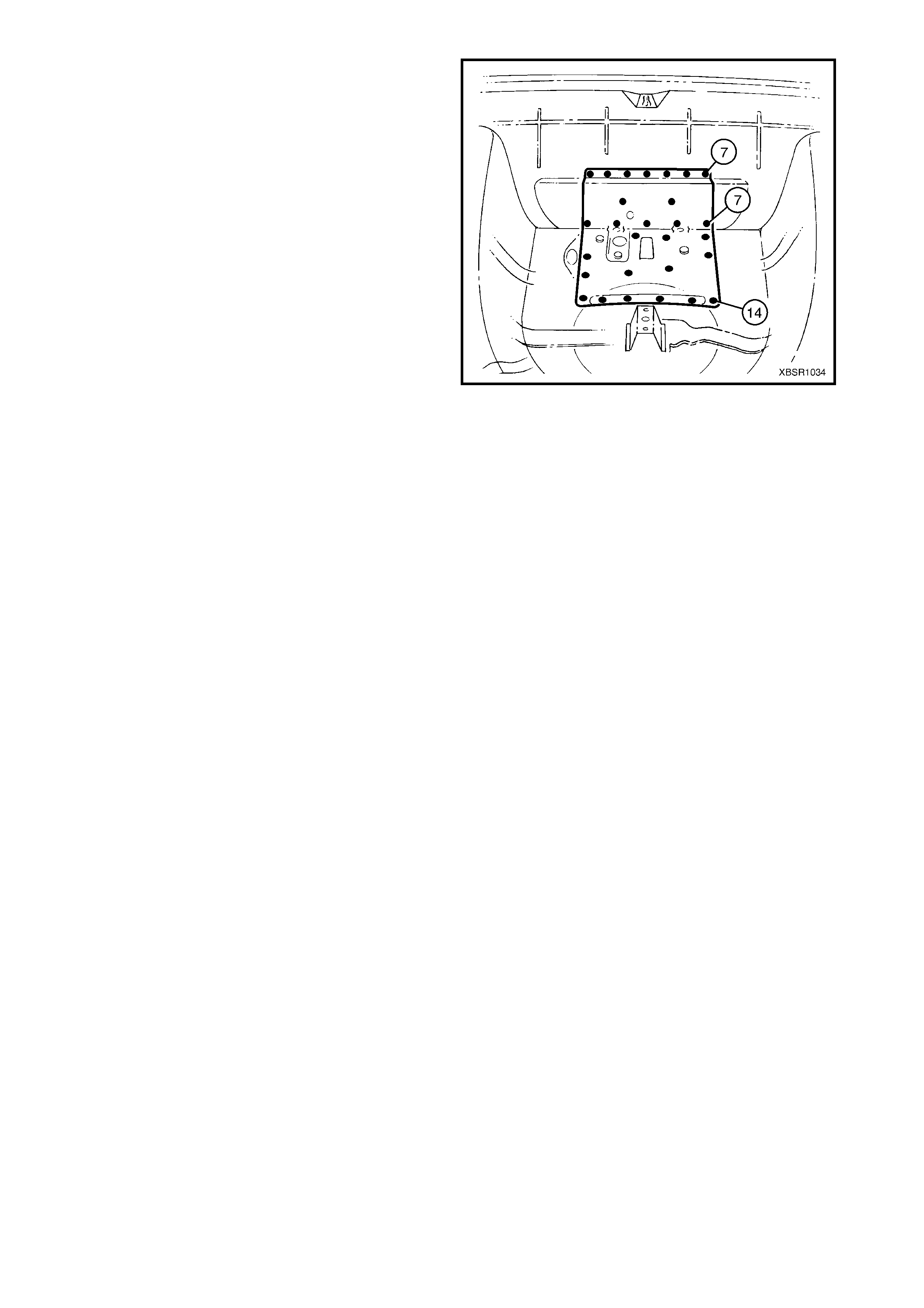
3. Plug weld the fuel tank support reinforcement
assembly to the rear compartment floor panel
assembly and rear end panel assembly.
4. Refinish and paint panels and other components
as required. Refer to Section 3, 1.3 PAINT
REFINISHING.
5. Apply Joint Sealer (Item 3) as required. Refer to
5. BODY SEALING, ADHESIVES & DEADENERS
in Section 3B.
6. Apply Cavity Wax (Item 8) as requir ed to the inside
of any box sections or areas inaccessible to paint,
refer to 6. CAVITY WAX in Section 3B.
7. Install the deadener panels as required, refer to
5.6 DEADENER PANELS & INSULATORS in
Section 3B.
8. Install the remaining components as described in
the appropriate Section of the MY 2003 VY & V2
Series II Service Information.
Figure 10B-24
2.5 REAR COMPERTMENT FLOOR PANEL OUTER EXTENSION – REPLACE
REMOVE
CAUTION: To avoid the possibility of fire, take
particular care when cutting or welding at the rear
of the vehicle. Remove the fuel tank and plug all
fuel lines.
1. Remove the adjacent bolt-on panels and
components as described in the appropriate
Section of the MY 2003 VY & V2 Series II Service
Information.
2. Remove the joint sealer from around the rear
compartment floor panel outer extension joins as
required.
3. Spot cut the welds attaching the rear compar tment
floor panel outer extension to the rear
compartment floor panel, rear side rail assembly,
quarter panel inner as sem bly and rear wheelhouse
inner panel as required, refer to Figure 10B-26.
Figure 10B-25
Figure 10B-26
4. Remove the extension from the vehicle and then repair any damage to adjacent parts as required.
5. Check and rectify the alignment of the body as required, refer to 3. BODY DIMENSIONS in Section 3B.
REPLACE
NOTE 1: Spot welding is the preferred method for attaching of panels and should be used whenever possible.
Where the spot welding equipment will not access the required weld position, a plug weld should be performed.
NOTE 2: The s ame number and pos ition of s pot welds (or plug welds) s hould be used when replac ing the panel,
as was used during manufacture, in order to maintain the original structural strength of the vehicle.
1. As required, mark the new panel with drilling locations in preparation for plug welding. Drill holes as required.
2. Prepare all mating surfaces and treat with Weld Through Primer (Item 1) as required, refer to
5. BODY SEALING, ADHESIVES & DEADENERS in Section 3B.
3. Spot or plug weld the left-hand web plate in
position as shown.
Figure 10B-27
4. Spot weld the right-hand web plate in position as
shown.
5. Refinish and paint panels and other components
as required. Refer to Section 3, 1.3 PAINT
REFINISHING.
6. Apply Joint Sealer (Item 3) as required. Refer to
5. BODY SEALING, ADHESIVES & DEADENERS
in Section 3B.
7. Apply Cavity Wax (Item 8) as requir ed to the inside
of any box sections or areas inaccessible to paint,
refer to 6. CAVITY WAX in Section 3B.
8. Apply Spray-on Deadener (Item 7) where
applicable, refer to 5. BODY SEALING,
ADHESIVES & DEADENERS in Section 3B.
9. Install the remaining components as described in
the appropriate Section of the MY 2003 VY & V2
Series II Service Information.
Figure 10B-28
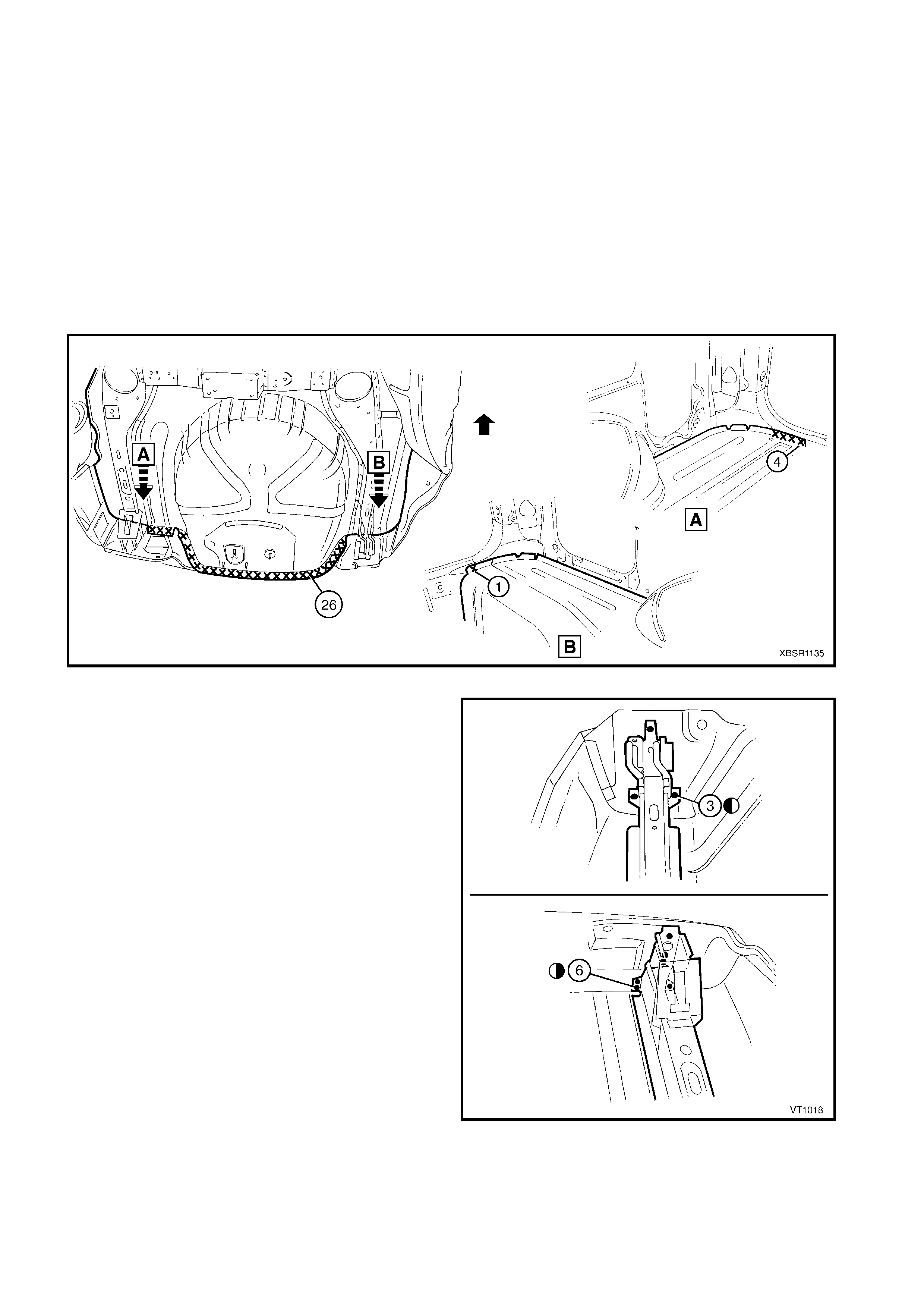
2.6 REAR COMPARTMENT FLOOR PANEL ASSEMBLY – REPLACE
REMOVE
CAUTION: To avoid the possibility of fire, take
particular care when cutting or welding at the rear
of the vehicle. Remove the fuel tank and plug all
fuel lines.
1. Remove the adjacent bolt-on panels and
components as described in the appropriate
Section of the MY 2003 VY & V2 Series II Service
Information.
2. Secure the vehicle on a suitable fixture and use a
suitable brace to maintain the alignment of the rear
side rail assemblies prior to removal of the rear
end panel assembly.
3. Remove the rear end panel assembly, refer to
2.2 REAR END PANEL ASSEMBLY – REPLACE.
4. Remove the j oint sealer f rom the s urrounding area
using a scraper and heat gun.
5. Spot cut the welds attaching the rear compar tment
floor panel assembly (1) to the rear floor panel
assembly (2), refer to Figure 10B-30.
6. Spot cut the welds attaching the rear compar tment
floor panel assembly to the rear side rail
assemblies.
Figure 10B-29
Figure 10B-30
7. Spot cut the welds attac hing the rear c om partm ent floor panel assem bly to the quarter panel inner assem bly
and rear wheelhouse inner panel assembly, refer to Figure 10B-31.
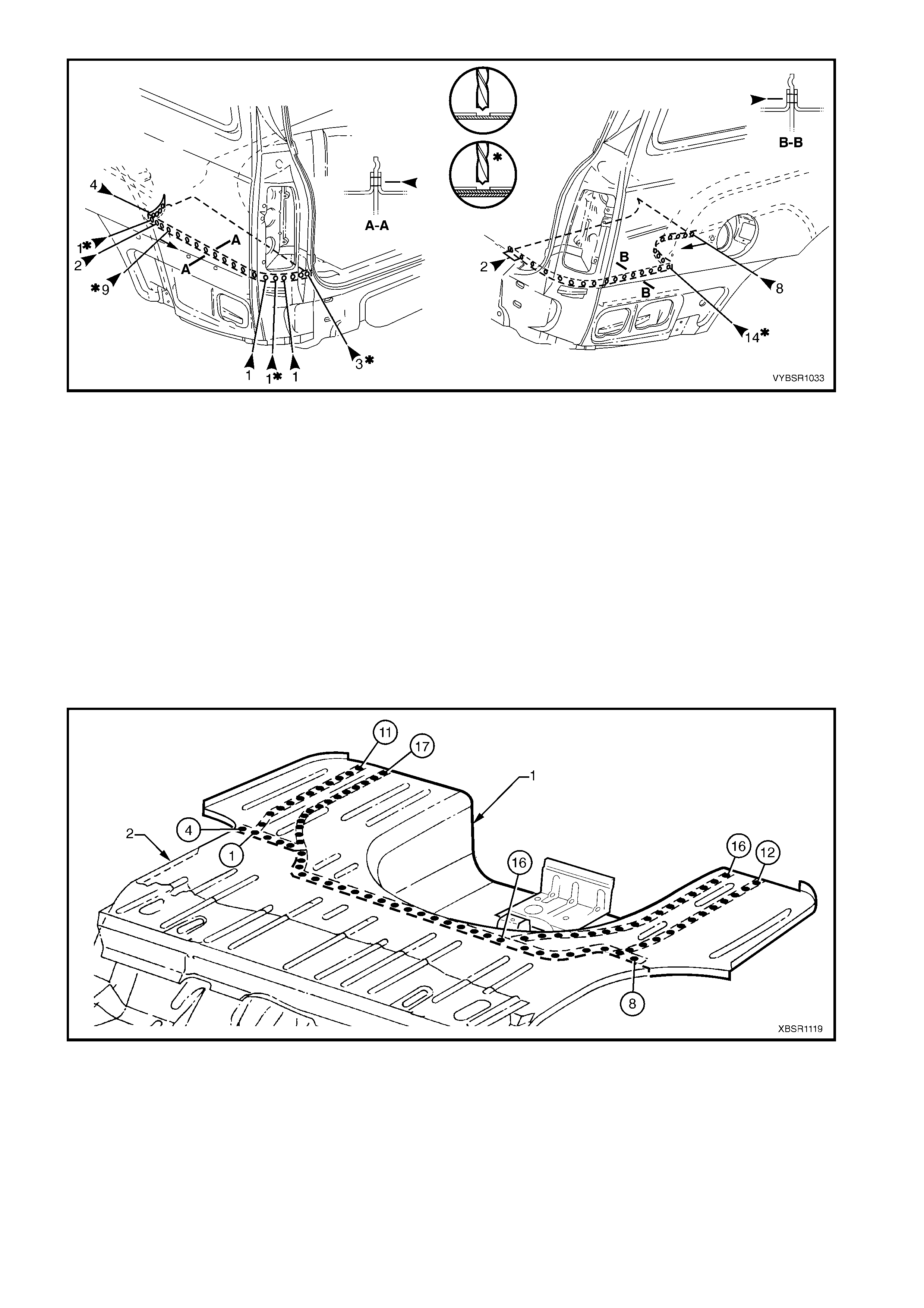
Figure 10B-31
8. Remove the floor panel assembly from the vehicle, then repair any damage to adjacent parts as required.
9. Check and rectify the alignment of the body as required, refer to 3. BODY DIMENSIONS in Section 3B.
REPLACE
NOTE 1: Spot welding is the preferred method for attaching of panels and should be used whenever possible.
Where the spot welding equipment will not access the required weld position, a plug weld should be performed.
NOTE 2: The s ame number and pos ition of s pot welds (or plug welds) s hould be used when replac ing the panel,
as was used during manufacture, in order to maintain the original structural strength of the vehicle.
1. As required, mark the new panel with drilling locations in preparation for plug welding. Drill holes as required.
2. Prepare all mating surfaces and treat with Weld Through Primer (Item 1) as required, refer to
5. BODY SEALING, ADHESIVES & DEADENERS in Section 3B.
3. Clamp the new rear compartment floor panel assembly in position and plug weld along the join to the rear
floor assembly, refer to Figure 10B-32.
4. Plug weld the rear compartment floor panel assembly to the rear side rail assemblies.
Figure 10B-32
5. Spot or plug the rear compartment floor panel assembly to the quarter panel inner assembly and rear
wheelhouse inner panel assembly, refer to Figure 10B-33.
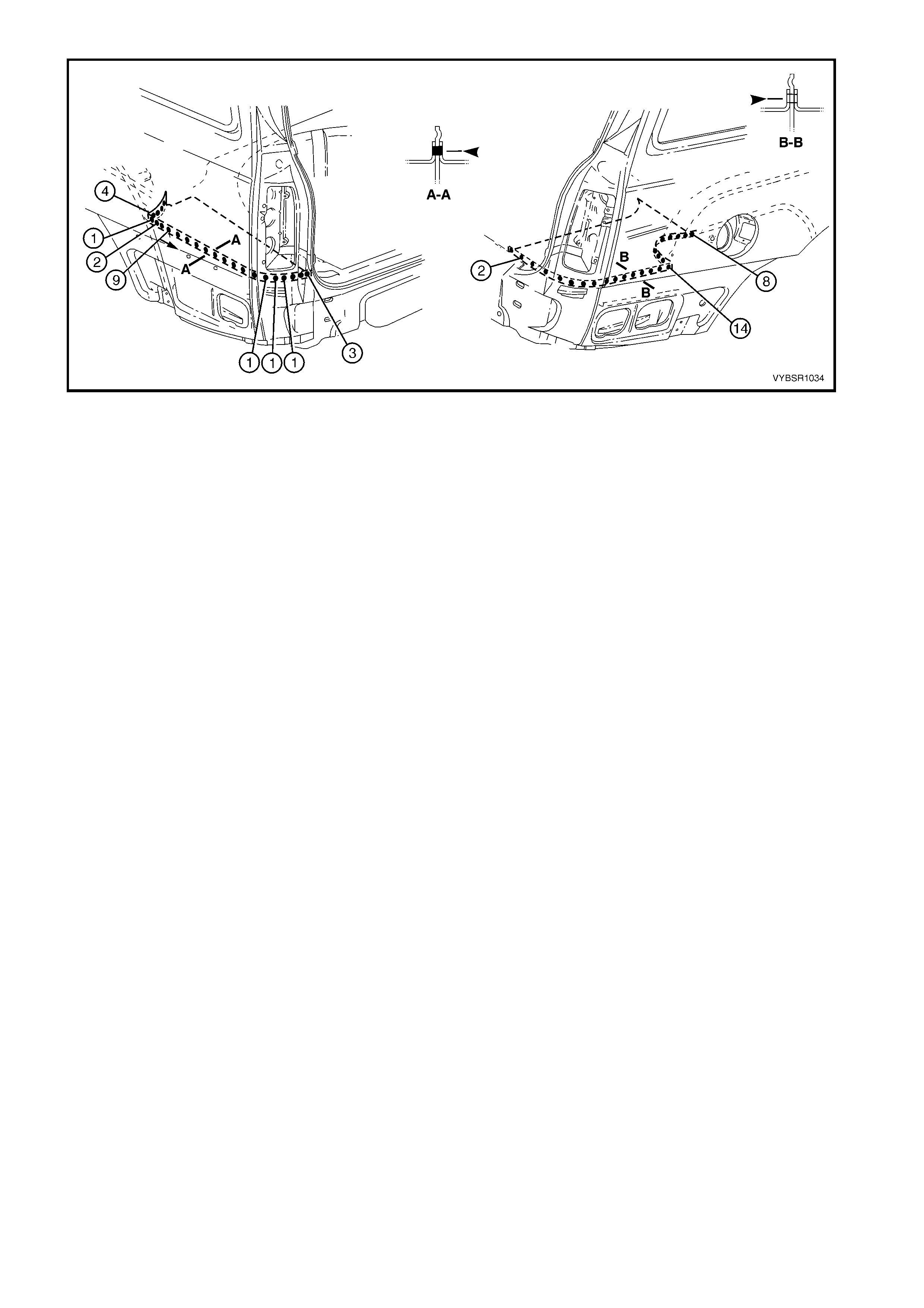
Figure 10B-33
6. Replace the rear end panel assembly, refer to 2.2 REAR END PANEL ASSEMBLY – REPLACE.
7. Refinish and paint panels and other components as required. Refer to Section 3, 1.3 PAINT REFINISHING.
8. Apply Joint Sealer (Item 3) as required. Refer to 5. BODY SEALING, ADHESIVES & DEADENERS in
Section 3B.
9. Apply deadener panels to the rear compartment floor panel, refer to 5.6 DEADENER PANELS &
INSULATORS in Section 3B.
10. Apply Cavity W ax (Item 8) as required to the ins ide of any box s ections or areas inacces sible to paint, refer
to 6. CAVITY WAX in Section 3B.
11. Install the rem aining com ponents as described in the appr opriate Section of the MY 2003 VY & V2 Series II
Service Information.
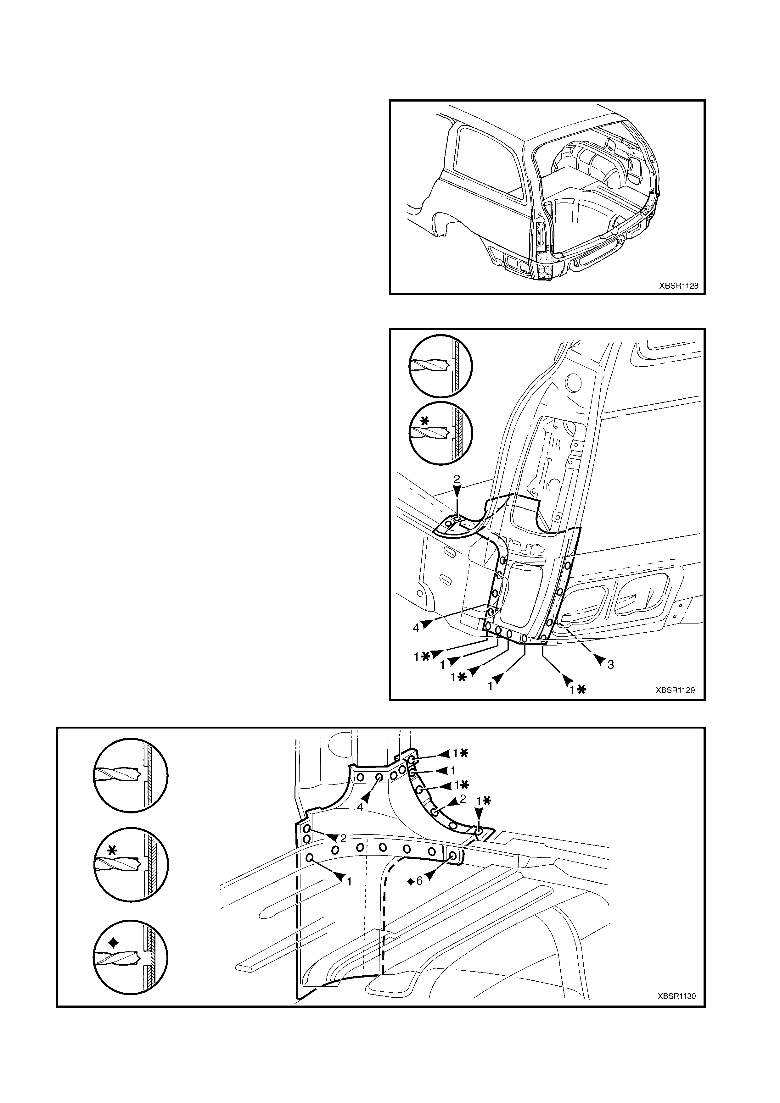
2.7 REAR WHEELHOUSE INNER PANEL ASSEMBLY – REPLACE
REMOVE
CAUTION: To avoid the possibility of fire, take
particular care when cutting or welding at the rear
of the vehicle. Remove the fuel tank and plug all
fuel lines.
1. Remove the adjacent bolt-on panels and
components as described in the appropriate
Section of the MY 2003 VY & V2 Series II Service
Information.
2. Secure the vehicle on a suitable fixture. As a
minimum, support the appropriate structural
sections of the vehicle on safety stands. Ensure
that the stands are clear of the sections being
removed.
3. Remove the adjoining panels as required, refer to
the appropriate Section in this Supplement.
Figure 10B-34
4. Spot cut the welds attaching the rear wheelhouse
brack et to the quar ter panel inner assem bly on the
relevant side of the vehicle.
5. Spot cut the welds attaching the rear wheelhouse
inner panel assembly to the rear floor panel
assembly and rear compartment floor panel
assembly on the relevant side of the vehicle, refer
to Figure 10B-36.
Figure 10B-35
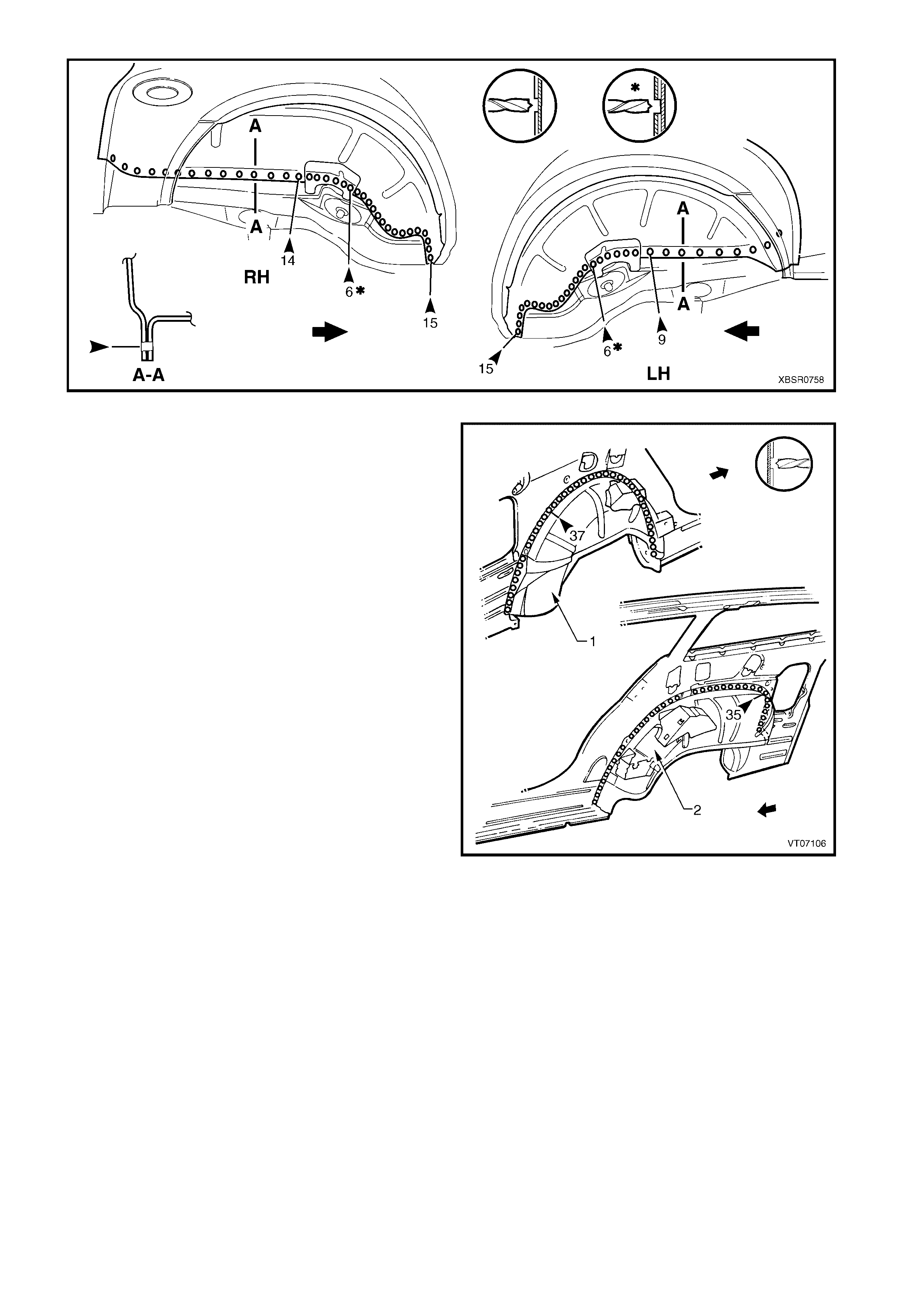
Figure 10B-36
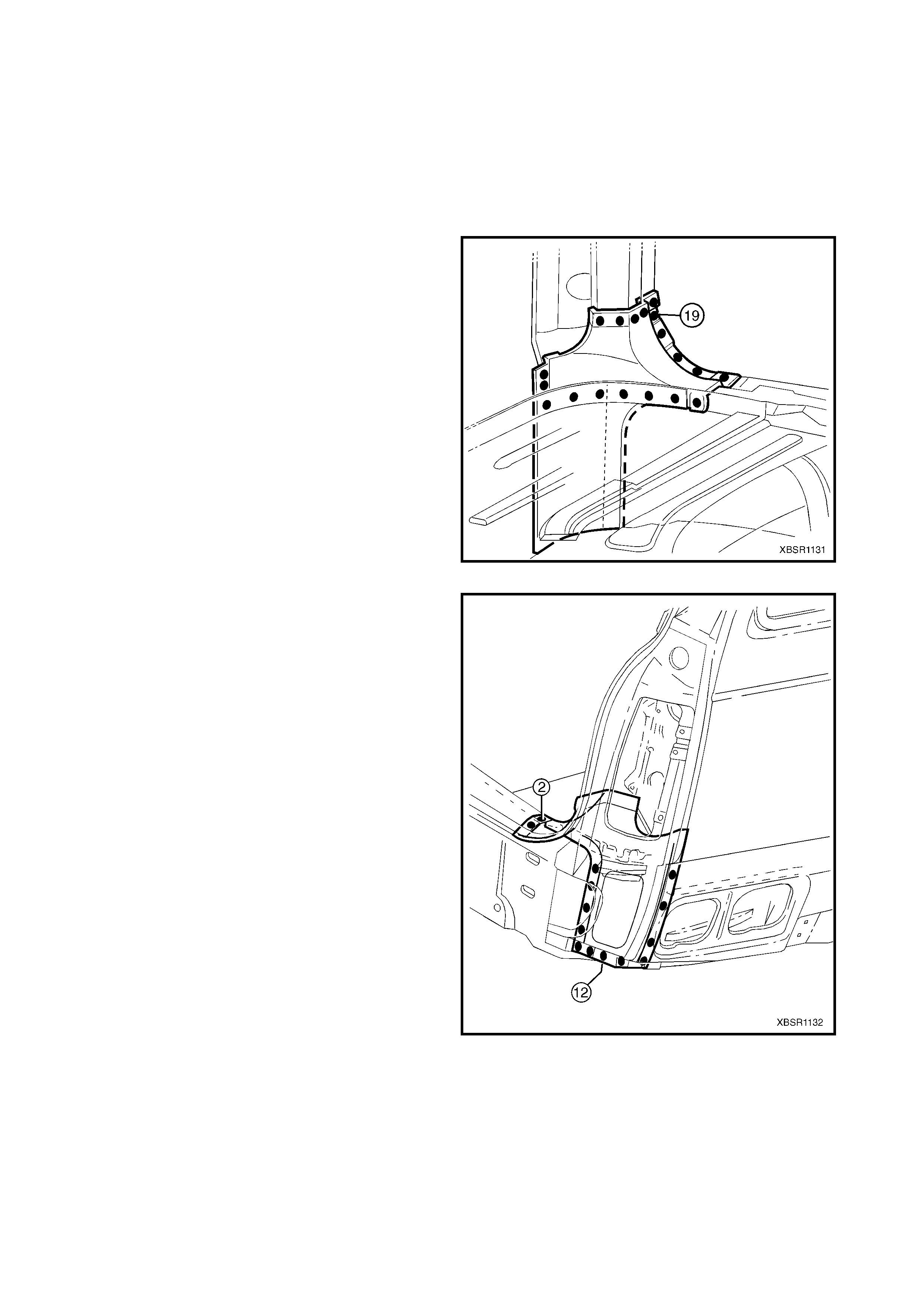
6. Spot cut the welds attaching the left-hand (1) or
right-hand (2) rear wheelhouse inner panel
assembly to the quarter panel inner assembly.
7. Remove the panel f r om the vehicle and then r epair
any damage to adjacent parts as required.
Figure 10B-37
REPLACE
NOTE 1: Spot welding is the preferred method for attaching of panels and should be used whenever possible.
Where the spot welding equipment will not access the required weld position, a plug weld should be performed.
NOTE 2: The s ame number and pos ition of s pot welds (or plug welds) s hould be used when replac ing the panel,
as was used during manufacture, in order to maintain the original structural strength of the vehicle.
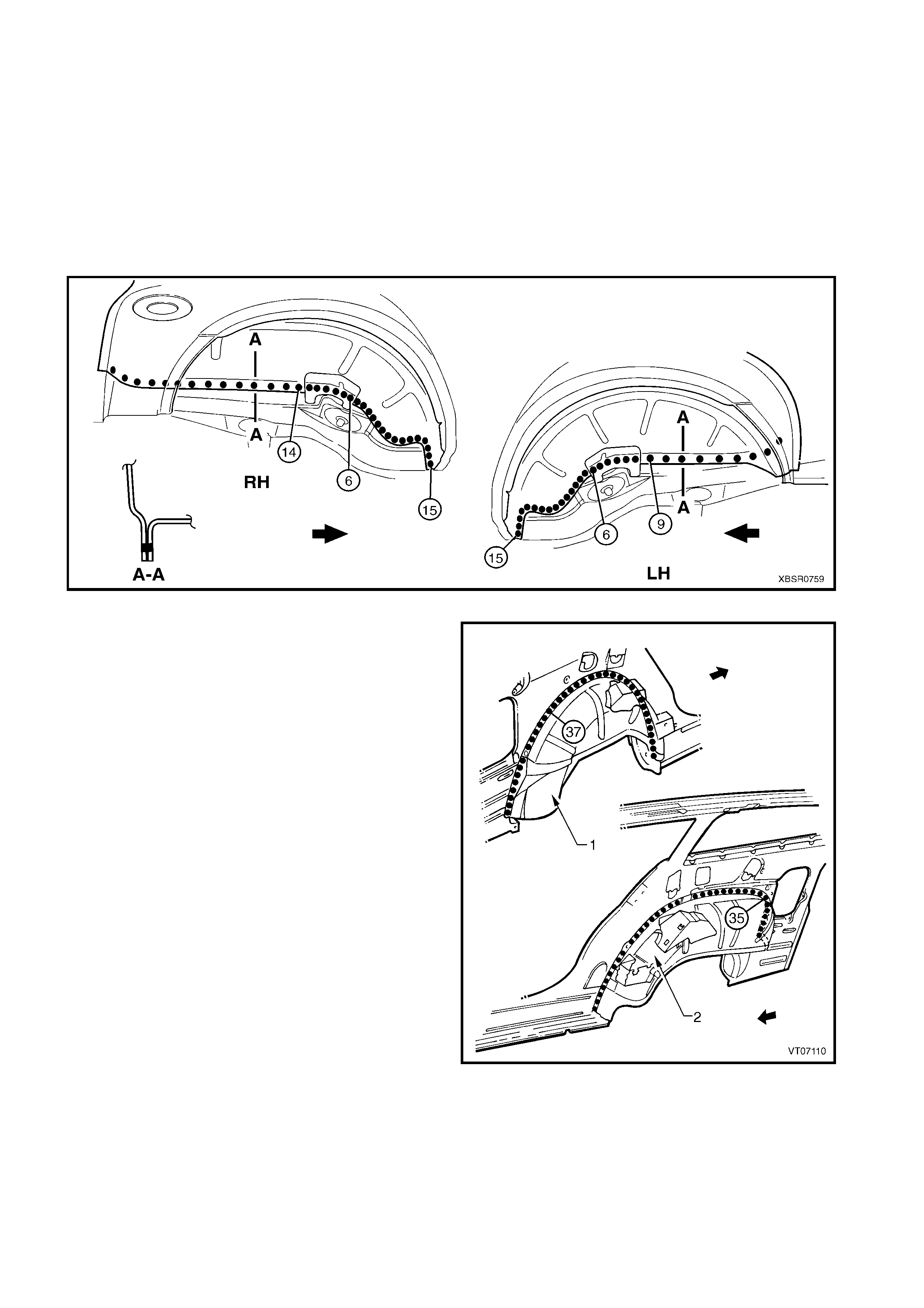
1. As required, mark the new panel with drilling locations in preparation for plug welding. Drill holes as required.
2. Prepare all mating surfaces and treat with Weld Through Primer (Item 1) as required, refer to
5. BODY SEALING, ADHESIVES & DEADENERS in Section 3B.
3. Clamp the new rear wheelhouse inner panel assembly in position and spot or plug weld to the rear floor
panel assembly and rear compartment floor panel assembly, refer to Figure 10B-38.
Figure 10B-38
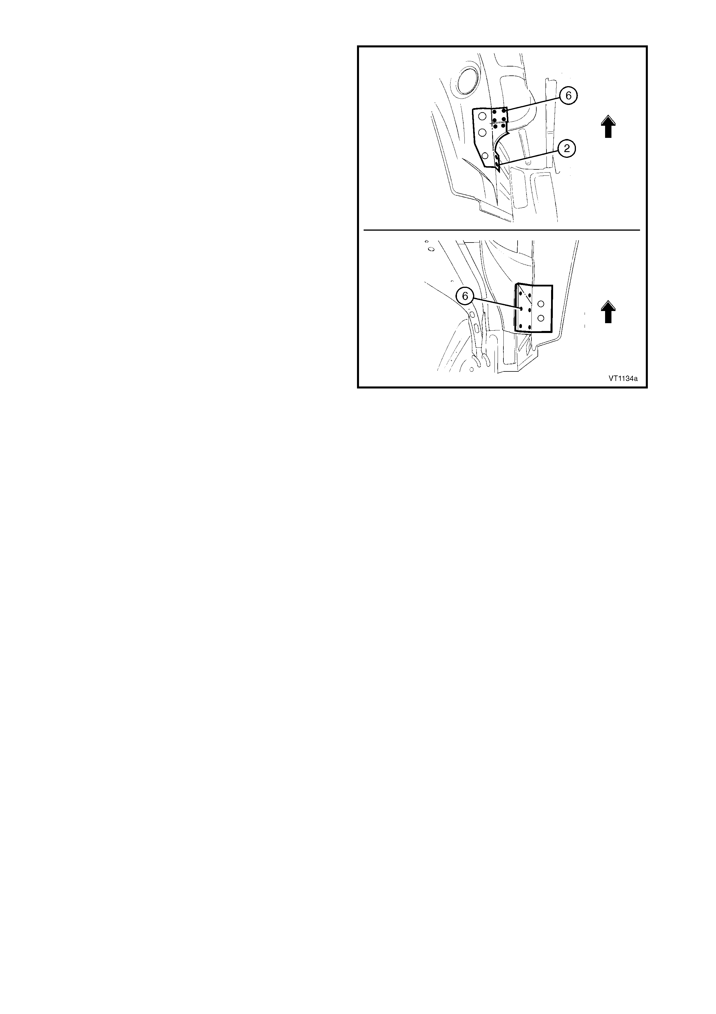
4. Plug weld the left-hand (1) or right-hand (2) rear
wheelhouse inner panel assembly to the quarter
panel inner assembly.
Figure 10B-39
5. Spot or plug weld the rear wheelhouse bracket to
the quarter panel inner assembly on the relevant
side of the vehicle.
6. Replace the adjoining panels as required, refer to
the appropriate Section in this Supplement.
7. Refinish and paint panels and other components
as required. Refer to Section 3, 1.3 PAINT
REFINISHING.
8. Apply Joint Sealer (Item 3) as required. Refer to
5. BODY SEALING, ADHESIVES & DEADENERS
in Section 3B.
9. Apply Spray-on Deadener (Item 7) where
applicable, refer to 5. BODY SEALING,
ADHESIVES & DEADENERS in Section 3B.
10. Apply Cavity Wax (Item 8) as requir ed to the inside
of any box sections or areas inaccessible to paint,
refer to 6. CAVITY WAX in Section 3B.
11. Install the remaining components as described in
the appropriate Section of the MY 2003 VY & V2
Series II Service Information.
Figure 10B-40
2.8 REAR FLOOR PANEL ASSEMBLY – REPLACE
REMOVE
CAUTION: To avoid the possibility of fire, take
particular care when cutting or welding at the rear
of the vehicle. Remove the fuel tank and plug all
fuel lines.
1. Remove the adjacent bolt-on panels and
components as described in the appropriate
Section of the MY 2003 VY & V2 Series II Service
Information.
2. Secure the vehicle on a suitable fixture. As a
minimum, support the appropriate structural
sections of the vehicle on safety stands. Ensure
that the stands are clear of the sections being
removed.
3. Remove the sealer and floor deadener panels
from the relevant areas using a scraper and heat
gun.
4. Remove the adjoining panels as required, refer to
the appropriate Section in this Supplement.
Figure 10B-41
5. Spot cut the welds attaching the park brake cable
bracket to the rear floor panel assembly.
Figure 10B-42
6. Spot cut the welds joining the front floor panel
assembly (1) and rear floor panel assembly (2).
7. Spot cut the welds attaching the rear floor panel
assembly to the inner rocker panel (3) each side.
Figure 10B-43
8. Spot cut the welds attaching the rear floor panel
assembly to the rear wheelhouse inner panel
assembly on both sides of the vehicle.
9. Spot cut the welds attaching the rear floor panel
assembly to the rear compartment floor panel
assem bly and crossm em ber assem bly No. 2, refer
to Figure 10B-45.
10. Spot cut the welds attaching the rear floor panel
assembly to the rear side rail assemblies, refer to
2.13 REAR SIDE RAIL ASSEMBLY – REPLACE.
11. Remove the rear floor panel assembly from the
vehicle and then repair any damage to adjacent
parts.
12. Check and rectify the alignment of the body as
required, refer to 3. BODY DIMENSIONS in
Section 3B.
Figure 10B-44
Figure 10B-45
REPLACE
NOTE 1: Spot welding is the preferred method for attaching of panels and should be used whenever possible.
Where the spot welding equipment will not access the required weld position, a plug weld should be performed.
NOTE 2: The s ame number and pos ition of s pot welds (or plug welds) s hould be used when replac ing the panel,
as was used during manufacture, in order to maintain the original structural strength of the vehicle.
1. As required, mark the new panel with drilling locations in preparation for plug welding. Drill holes as required.
2. Prepare all mating surfaces and treat with Weld Through Primer (Item 1) as required, refer to
5. BODY SEALING, ADHESIVES & DEADENERS in Section 3B.
3. Clam p the new rear floor panel assembly in position and plug weld to the rear compartm ent floor assem bly
and crossmember assembly No 2, refer to Figure 10B-46.
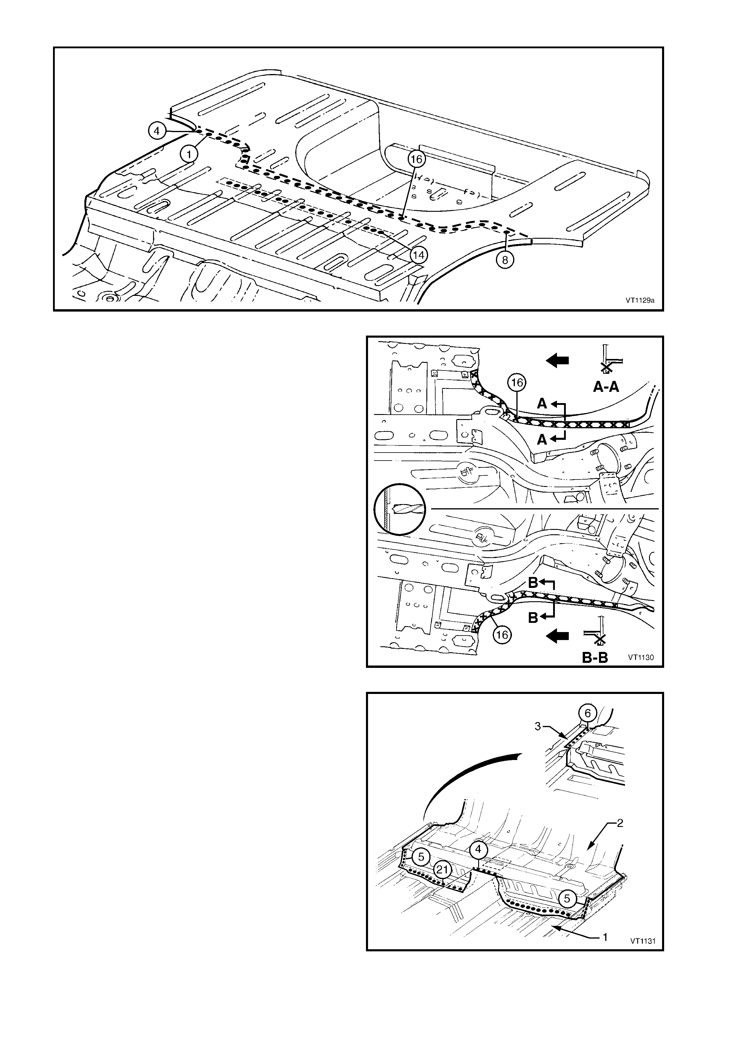
Figure 10B-46
4. Spot weld the rear floor assembly to the rear
wheelhouse inner panel assem bly on both sides of
the vehicle.
5. Plug weld the rear floor panel ass embly to the rear
side rail assemblies, refer to 2.13 REAR SIDE
RAIL ASSEMBLY – REPLACE.
Figure 10B-47
6. Plug weld the rear floor panel assembly (2) to the
front floor panel assembly (1).
7. Plug weld the rear floor panel assembly to the
inner rocker panel (3) each side.
Figure 10B-48
8. Plug weld the park brake cable bracket to the rear
floor panel assembly.
9. Replac e any other rem oved panels as desc r ibed in
the appropriate Section in this Supplement.
10. Refinish and paint panels and other components
as required. Refer to Section 3, 1.3 PAINT
REFINISHING.
11. Apply Joint Sealer (Item 3) as required. Refer to
5. BODY SEALING, ADHESIVES & DEADENERS
in Section 3B.
12. Apply Cavity Wax (Item 8) as requir ed to the inside
of any box sections or areas inaccessible to paint,
refer to 6. CAVITY WAX in Section 3B.
13. Apply Spray-on Deadener (Item 7) where
applicable, refer to 5. BODY SEALING,
ADHESIVES & DEADENERS in Section 3B.
14. Apply deadener panels to the rear compartment
floor panel, refer to 5.6 DEADENER PANELS &
INSULATORS in Section 3B.
15. Install the remaining components as described in
the appropriate Section of the MY 2003 VY & V2
Series II Service Information.
Figure 10B-49
2.9 REAR BUMPER IMPACT BAR BRACE ASSEMBLY – REPLACE
REMOVE
CAUTION: To avoid the possibility of fire, take
particular care when cutting or welding at the rear
of the vehicle. Remove the fuel tank and plug the
fuel lines.
1. Remove the adjacent bolt-on panels and
components as described in the appropriate
Section of the MY 2003 VY & V2 Series II Service
Information.
2. Secure the vehicle on a suitable fixture. As a
minimum, support the appropriate structural
sections of the vehicle on safety stands. Ensure
that the stands are clear of the sections being
removed.
3. Remove the adjoining panels as required, refer to
the appropriate Section of this Supplement.
4. Spot cut the welds attaching the left-hand (1) or
right-hand (2) rear bumper impact bar brace
assembly to the rear side rail ass embly (3), refer to
Figure 10B-51.
5. If required, for the right-hand rear bumper impact
bar brace assembly, remove the closing plate (4).
Figure 10B-50
Figure 10B-51
REPLACE
NOTE 1: Spot welding is the preferred method for attaching of panels and should be used whenever possible.
Where the spot welding equipment will not access the required weld position, a plug weld should be performed.
NOTE 2: The s ame number and pos ition of s pot welds (or plug welds) s hould be used when replac ing the panel,
as was used during manufacture, in order to maintain the original structural strength of the vehicle.
1. As required, mark the new panel with drilling locations in preparation for plug welding. Drill holes as required.
2. Prepare all mating surfaces and treat with Weld Through Primer (Item 1) as required, refer to
5. BODY SEALING, ADHESIVES & DEADENERS in Section 3B.
3. Clamp and plug weld the rear bumper impact bar brace assembly (1 or 2) in position on the rear side rail
assembly (3).
4. If required, for the right-hand side clamp and plug weld the closing plate (4) in position, refer to Figure
10B-52.
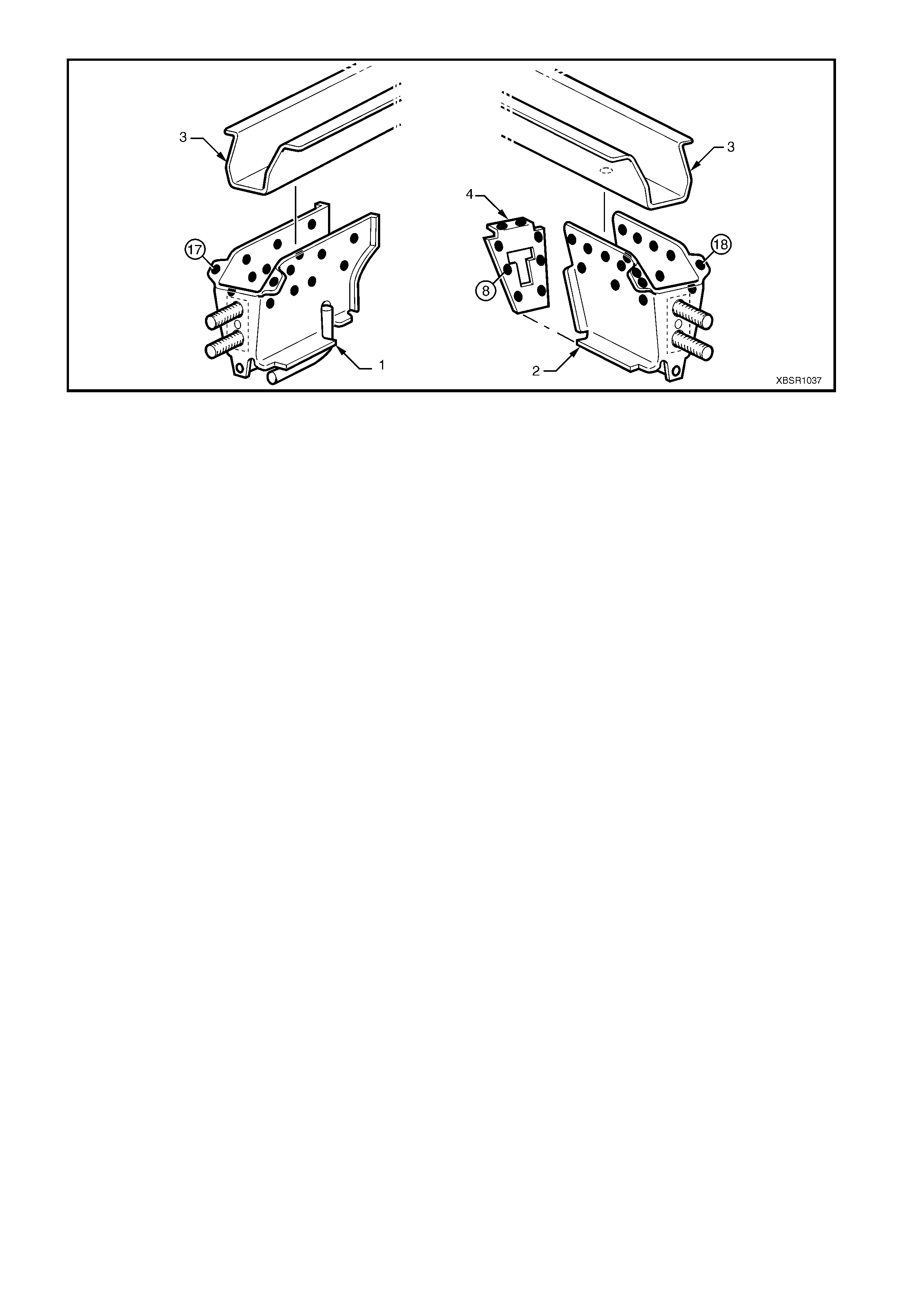
Figure 10B-52
5. Install other panels as required, refer to the appropriate Section in this Supplement.
6. Refinish and paint panels and other components as required. Refer to Section 3, 1.3 PAINT REFINISHING.
7. Apply Joint Sealer (Item 3) as required. Refer to 5. BODY SEALING, ADHESIVES & DEADENERS in
Section 3B.
8. Apply Cavity Wax (Item 8) as required to the ins ide of any box s ections or areas inacces sible to paint, refer
to 6. CAVITY WAX in Section 3B.
9. Ins tall the remaining c omponents as des cribed in the appropriate Section of the MY 2003 VY & V2 Series II
Service Information.
2.10 CROSSMEMBER ASSEMBLY NO. 2 – REPLACE
REMOVE
CAUTION: To avoid the possibility of fire, take
particular care when cutting or welding at the rear
of the vehicle. Remove the fuel tank and plug all
fuel lines.
1. Rem ove the adjacent components as described in
the appropriate Section of the MY 2003 VY & V2
Series II Service Information.
2. Secure the vehicle on a suitable fixture. As a
minimum, support the appropriate structural
sections of the vehicle on safety stands.
Figure 10B-53
3. Spot cut the welds attaching the crossmember
No.2 to the crossmember bracket and to the rear
side rail, on each side of the vehicle.
NOTE: Take care not to damage the crossmember
brackets when removing the crossmember, as these
parts are only serviced as part of the rear side rail
assemblies.
Figure 10B-54
4. Spot cut the welds attaching the crossmember to
the rear compartment floor panel assembly.
5. Remove the crossmember from the vehicle, and
then repair any damage to adjacent parts as
required.
6. Check and rectify the alignment of the body as
required, refer to 3. BODY DIMENSIONS in
Section 3B.
Figure 10B-55
REPLACE
NOTE 1: Spot welding is the preferred method for attaching of panels and should be used whenever possible.
Where the spot welding equipment will not access the required weld position, a plug weld should be performed.
NOTE 2: The s ame number and pos ition of s pot welds (or plug welds) s hould be used when replac ing the panel,
as was used during manufacture, in order to maintain the original structural strength of the vehicle.
1. As required, mark the new panel with drilling locations in preparation for plug welding. Drill holes as required.
2. Prepare all mating surfaces and treat with Weld Through Primer (Item 1) as required, refer to
5. BODY SEALING, ADHESIVES & DEADENERS in Section 3B.
3. Plug weld the crossmember to the crossmember
bracket and rear side rail, on each side of the
vehicle.
Figure 10B-56
4. Plug weld the crossmember to the rear
compartment floor panel assembly.
5. Refinish and paint panels and other components
as required. Refer to Section 3, 1.3 PAINT
REFINISHING.
6. Apply Joint Sealer (Item 3) as required. Refer to
5. BODY SEALING, ADHESIVES & DEADENERS
in Section 3B.
7. Apply Cavity Wax (Item 8) as requir ed to the inside
of any box sections or areas inaccessible to paint,
refer to 6. CAVITY WAX in Section 3B.
8. Apply Spray-on Deadener (Item 7) where
applicable, refer to 5. BODY SEALING,
ADHESIVES & DEADENERS in Section 3B.
9. Install the remaining components as described in
the appropriate Section of the MY 2003 VY & V2
Series II Service Information.
Figure 10B-57
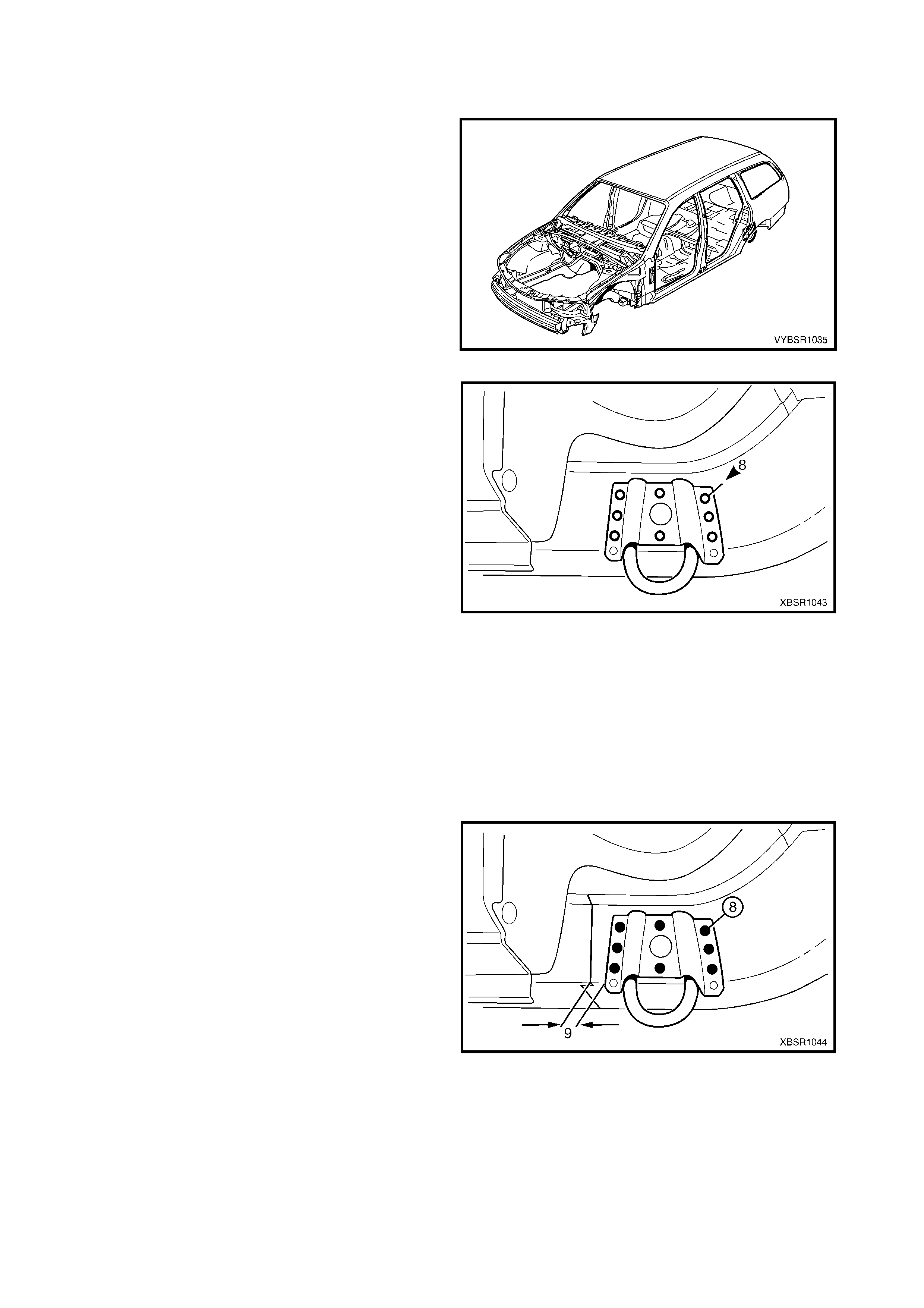
2.11 REAR TIE DOWN ASSEMBLY – REPLACE
REMOVE
1. Rem ove the adjacent components as described in
the appropriate Section of the MY 2003 VY & V2
Series II Service Information.
Figure 10B-58
2. Spot cut the welds attaching the tie down hook
assembly to the rear side rail assembly and
remove.
Figure 10B-59
REPLACE
NOTE 1: Spot welding is the preferred method for attaching of panels and should be used whenever possible.
Where the spot welding equipment will not access the required weld position, a plug weld should be performed.
NOTE 2: The s ame number and pos ition of s pot welds (or plug welds) s hould be used when replac ing the panel,
as was used during manufacture, in order to maintain the original structural strength of the vehicle.
1. As required, mark the new panel with drilling locations in preparation for plug welding. Drill holes as required.
2. Prepare all mating surfaces and treat with Weld Through Primer (Item 1) as required, refer to
5. BODY SEALING, ADHESIVES & DEADENERS in Section 3B.
3. Install the tie down hook assembly onto the rear
side rail assembly, approximately 9 mm rearward
of the join.
4. Plug weld the tie down hook assembly to the rear
side rail assembly, eight places.
5. Refinish and paint panels and other components
as required. Refer to Section 3, 1.3 PAINT
REFINISHING.
6. Apply Cavity Wax (Item 8) as requir ed to the inside
of any box sections or areas inaccessible to paint,
refer to 6. CAVITY WAX in Section 3B.
7. Install the remaining components as described in
the appropriate Section of the MY 2003 VY & V2
Series II Service Information.
Figure 10B-60
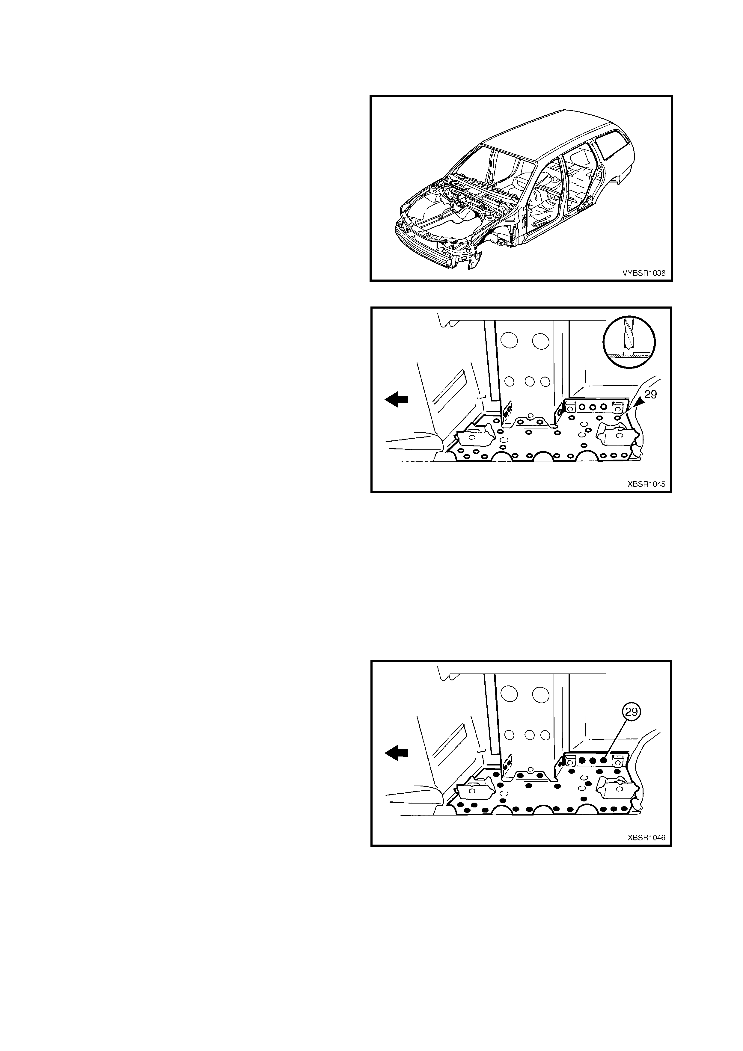
2.12 REAR FLOOR PANEL OUTER EXTENSION – REPLACE
REMOVE
1. Rem ove the adjacent components as described in
the appropriate Section of the MY 2003 VY & V2
Series II Service Information.
Figure 10B-61
2. Spot cut the welds attaching the rear floor panel
outer extension to the inner rocker panel and rear
side rail assembly and remove.
Figure 10B-62
REPLACE
NOTE 1: Spot welding is the preferred method for attaching of panels and should be used whenever possible.
Where the spot welding equipment will not access the required weld position, a plug weld should be performed.
NOTE 2: The s ame number and pos ition of s pot welds (or plug welds) s hould be used when replac ing the panel,
as was used during manufacture, in order to maintain the original structural strength of the vehicle.
1. As required, mark the new panel with drilling locations in preparation for plug welding. Drill holes as required.
2. Prepare all mating surfaces and treat with Weld Through Primer (Item 1) as required, refer to
5. BODY SEALING, ADHESIVES & DEADENERS in Section 3B.
3. Install and plug weld the rear floor panel outer
extension to the inner rocker panel and rear side
rail assembly.
4. Refinish and paint panels and other components
as required. Refer to Section 3, 1.3 PAINT
REFINISHING.
5. Apply Cavity Wax (Item 8) as requir ed to the inside
of any box sections or areas inaccessible to paint,
refer to 6. CAVITY WAX in Section 3B.
6. Install the remaining components as described in
the appropriate Section of the MY 2003 VY & V2
Series II Service Information.
Figure 10B-63
2.13 REAR SIDE RAIL ASSEMBLY – REPLACE
REMOVE
CAUTION: To avoid the possibility of fire, take
particular care when cutting or welding at the rear
of the vehicle. Remove the fuel tank and plug all
fuel lines.
1. Rem ove the adjacent components as described in
the appropriate Section of the MY 2003 VY & V2
Series II Service Information.
2. Secure the vehicle on a suitable fixture. As a
minimum, support the appropriate structural
sections of the vehicle on safety stands. Ensure
that the stands are clear of the rear side rail
assembly(s) being removed.
Figure 10B-64
3. Spot cut the welds attaching the crossmember
No.2 to the crossmember bracket and to the rear
side rail, on each side of the vehicle.
Figure 10A-1
4. Spot cut the welds attaching the rear side rail
assembly to the rear floor panel assembly.
Figure 10B-65
5. Spot cut the welds attaching the rear side rail
assembly to the rear floor panel assembly.
Figure 10B-66
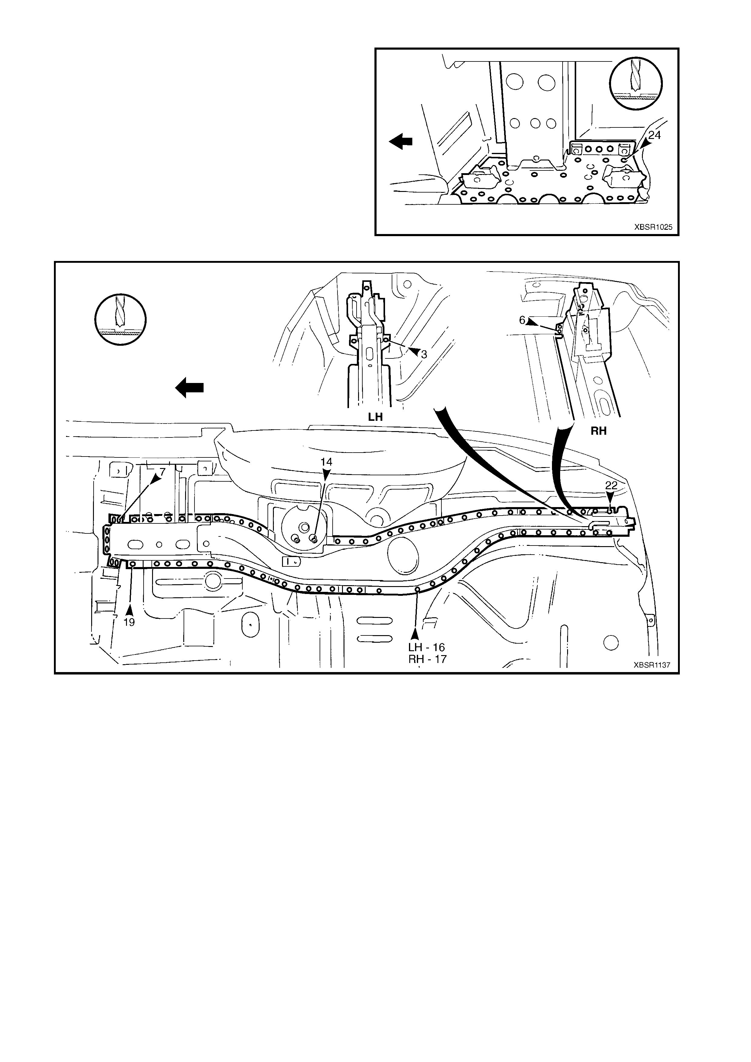
6. Spot cut the welds attaching the rear floor panel
outer extension to the inner rocker panel
assembly.
7. Spot cut the rear side rail assembly from the rear
floor panel assembly, rear compartment floor
panel assembly and the rear end panel, refer to
Figure 10B-68.
NOTE: Ther e are a dif f erent num ber of welds between
the left-hand and right-hand sides.
8. Remove the rear side rail assembly from the
vehicle.
Figure 10B-67
Figure 10B-68
9. Repair damage to adjacent parts as required.
10. Check and rectify the alignment of the body as required, refer to 3. BODY DIMENSIONS in Section 3B.
REPLACE
NOTE 1: Spot welding is the preferred method for attaching of panels and should be used whenever possible.
Where the spot welding equipment will not access the required weld position, a plug weld should be performed.
NOTE 2: The s ame number and pos ition of s pot welds (or plug welds) s hould be used when replac ing the panel,
as was used during manufacture, in order to maintain the original structural strength of the vehicle.
1. As required, mark the new panel with drilling locations in preparation for plug welding. Drill holes as required.
2. Prepare all mating surfaces and treat with Weld Through Primer (Item 1) as required, refer to
5. BODY SEALING, ADHESIVES & DEADENERS in Section 3B.
CAUTION: Prior to plug welding in this region, remove the deadener from the inside floor to remove the
risk of fire.
3. Locate and clamp the new rear side rail assembly in position and check and adjust its alignment, refer to
3. BODY DIMENSIONS in Section 3B.
4. Plug weld the rear side rail assembly to the rear floor panel assembly, rear compartment floor panel
assembly and the rear end panel, refer to Figure 10B-69.
Figure 10B-69
5. Plug weld the rear side rail assembly to the rear
floor panel assembly.
Figure 10B-70
6. Plug weld the crossm em ber assem bly No. 2 to the
crossmember bracket and rear side rail.
Figure 10B-71
7. Plug weld the rear side rail assembly to the rear
floor panel ass embly and the rear floor panel outer
extension to the inner rocker panel assembly.
8. Refinish and paint panels and other components
as required. Refer to Section 3, 1.3 PAINT
REFINISHING.
9. Apply Joint Sealer (Item 3) as required. Refer to
5. BODY SEALING, ADHESIVES & DEADENERS
in Section 3B.
10. Apply Cavity Wax (Item 8) as requir ed to the inside
of any box sections or areas inaccessible to paint,
refer to 6. CAVITY WAX in Section 3B.
11. Install the remaining components as described in
the appropriate Section of the MY 2003 VY & V2
Series II Service Information.
Figure 10B-72