
Precautions Page 2–1
Page 2–1
Section 2
Precautions
ATTENTION
Before performing any Service Operation or other procedure described in this Section, refer to Section 00
Warnings, Cautions and Notes for correct workshop practices with regard to safety and/or property damage.
The Structure of the MY 2004 WK Series body
shell has been developed using complex
design and development techniques. In
addition to meeting all required standards, the
vehicle body is also a critical part of the
overall safety systems. It is therefore
imperative the repair procedures described
here are adhered to during all vehicle body
repairs.
1 General Information............................................................................................................................... 2
2 Electrical Precautions ........................................................................................................................... 3
2.1 Electronic Devices .................................................................................................................................................3
2.2 Before Repairing The Vehicle................................................................................................................................4
Radio And Audio Equipment.................................................................................................................................4
Instrumentation......................................................................................................................................................5
Cellular Mobile Phones..........................................................................................................................................5
Paint Ovens.............................................................................................................................................................5
Welding ...................................................................................................................................................................5
2.3 Location Of Electronic Control Devices...............................................................................................................6
3 Cavity Foam.......................................................................................................................................... 11
Replace .................................................................................................................................................................11

Precautions Page 2–2
Page 2–2
1 General Information
With the following exceptions, MY 2004 WK Series precautions information carries over from MY 2003 VY Series
Vehicles. For information not contained within this Section, refer to Section 2, Precaution s, in the MY 2003 VY & V2
Series Service Information Supplement, Body Structure Repair.
• Electric al Pr ecautions
• Cavity Foam
This Section contains important information regarding the precautions that are to be observed when performing repair
work on MY 2004 WK Series vehicles.
The reasons for these precautions are threefold. Firstly, it is important that the safety of those repairing the vehicle is not
compromised. Secondly, it must be ensured that inadvertent damage is not caused to the vehicle during the preparation
for, or during the performance of, repairs to that vehicle. Finally, it must be ensured that any relevant Federal and State
legislation is abided by.
NOTE
This Section, along with Section 00 Cautions &
Notes in the MY 2003 VY Series & V2 Series II
Service Information should be thoroughly read
and understood before any repair work is
commenced on MY 2004 WK Series vehicles.
This Section shows the location of the electronic devices and where to replace cavity foam for MY 2004 WK Series
vehicles.

Precautions Page 2–3
Page 2–3
2 Electrical Precautions
2.1 Electronic Devices
MY 2004 WK Series vehicles are equipped with many electronic devices as standard equipment to monitor and control
various vehicle functions.
These electronic devices are susceptible to damage from severe shock, transient voltage and high temperatures.
Particular note should be taken of the
Powertrain Control Module (PCM), which is
located on the left-hand hinge pillar panel.
Heat, or transient voltage produced by spot,
MIG or arc welding techniques will cause
damage to the electrical components within
the PCM. Always disconnect the battery and
unplug and remove the PCM before repairing
the vehicle.
It is worth noting that other equipm ent, su ch as instr um ents , radio s, mobi le tele phon es and v arious after market
accessories are also controlled by electronics and are therefore subject to similar precautions. Refer to Figure 2 – 1
through Figure 2 – 5 for the electronic devices and their locations.

Precautions Page 2–4
Page 2–4
2.2 Before Repairing The Vehicle
Disconnection of the battery affects
certain vehicle electronic systems. Refer to
Section 00, 5 Battery Disconnection
Procedures in the MY 2003 VY & V2 Series II
Service Information before disconnecting the
battery.
1 Disconnect both the negative and positive cables from the battery terminals.
2 Unplug the harnesses and remov e the PCM from the left side hinge pillar pane l.
3 Check the area adjacent to the damage for electronic devices, particularly behind trim panels and under the
dashboard.
4 Remove any units that may have been damaged in the impact or may be damaged during repairs.
Radio And Audio Equipment
As a theft deterrent, all vehicles are fitted with
a security coded audio system. After the
power supply is interrupted, the radio will
remain inoperative after reinstallation until the
PIN number is entered into the system. The
procedure is described in the instructions
accompanying the radio.
Radios and other forms of audio equipment should be treated with due care. Before removing the equipment or
commencing repairs to the vehicle, consult the radio operator’s manual accompanying the vehicle for precautionary
details. Always disconnect both the negative and positive cables from the battery terminals. Never have the radio
operating while repairing the vehicle.

Precautions Page 2–5
Page 2–5
Instrumentation
The instruments can be damaged by impact,
or temperatures above 80°C. Always remove
the instrument cluster before subjecting the
vehicle to temperatures above 80°C.
Cellular Mobile Phones
Transient voltage and magnetic pulses can
easily damage mobile phones and other
communications equipment. Such
communications equipment sometimes has
the control unit mounted in the luggage
compartment or in other out of sight areas.
Refer to the operator’s instructions
accompanying the particular unit for
precautions.
Paint Oven s
The high temperatures produced in a paint
oven can damage the electronic control
devices and some trim items in the vehicle.
Remove all electronic devices, plastic or
fabric trim items and the dashboard
assembly, before placing the vehicle in a
paint oven that will achieve temperatures
above 70°C.
Welding
MIG or arc welding produces transient voltages that may damage the electronic control devices unless the following
precautions are observed:
1 Always disconnect both terminals of the battery and remove the Powertrain Control Module (PCM) before repairing
any part of the vehicle.
2 Ensure that the earth clamp is located as close as possible to the welding site.
3 Check behind the panels being welded for wiring harnesses. Reposition any harness to avoid damage.
4 In the vicinity of the repairs, disconnect the wiring harness body earth points.
5 Remove any electronic control devices from areas near the damage, refer to Figure 2 – 1 through Figure 2 – 5.
Precautions Page 2–6
Page 2–6
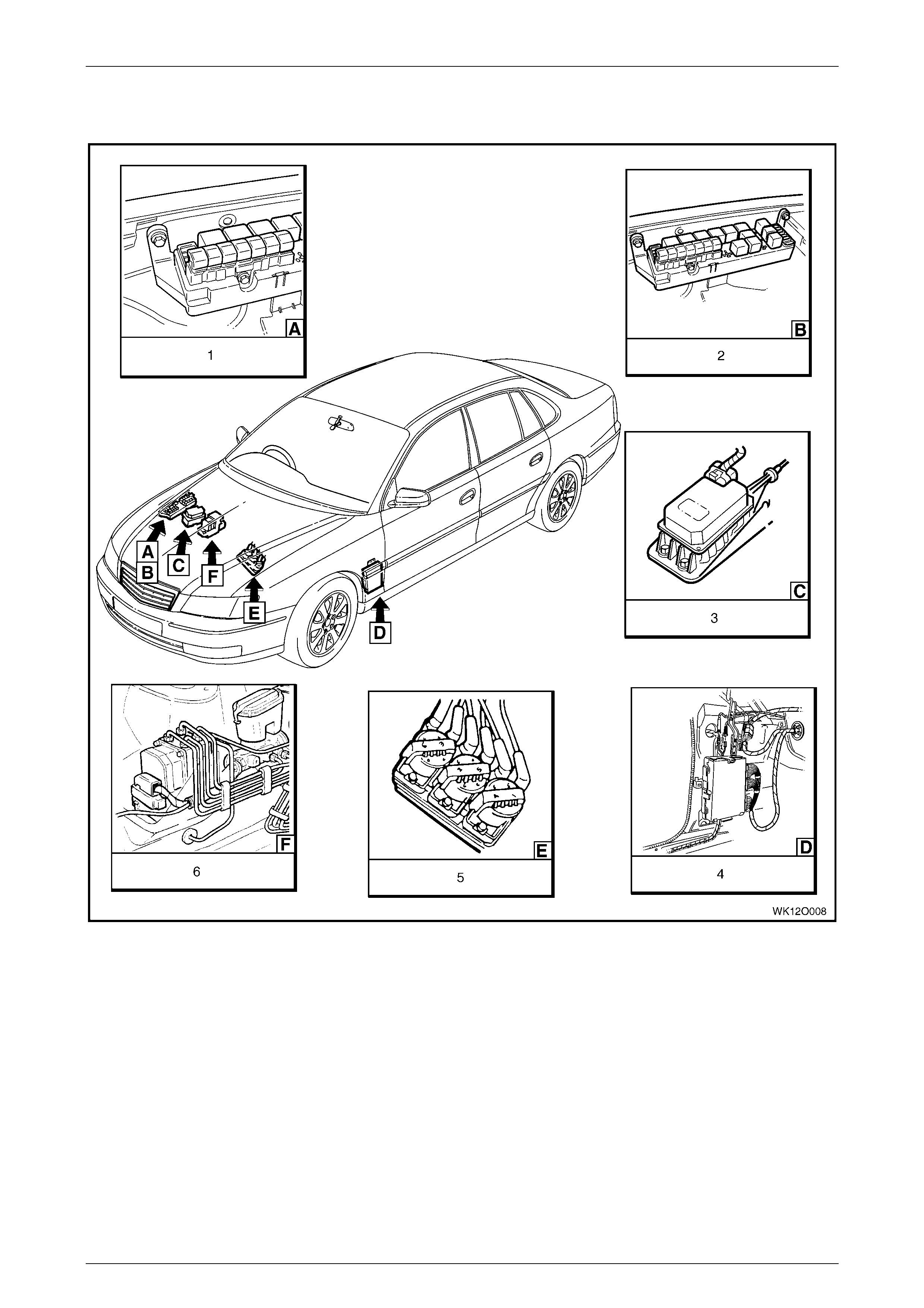
2.3 Location Of Electronic Control Devices
Figure 2 – 1
Legend
1 Fusible Links
2 Relays & Fuses – Engine compartment
3 Cruise Control Module
4 Powertrain Interface Module (PIM) – V6 Engine
5 Direct Ignition System (DIS) Module – V6 Engine
6 ABS Hydraulic Modulator
Precautions Page 2–7
Page 2–7
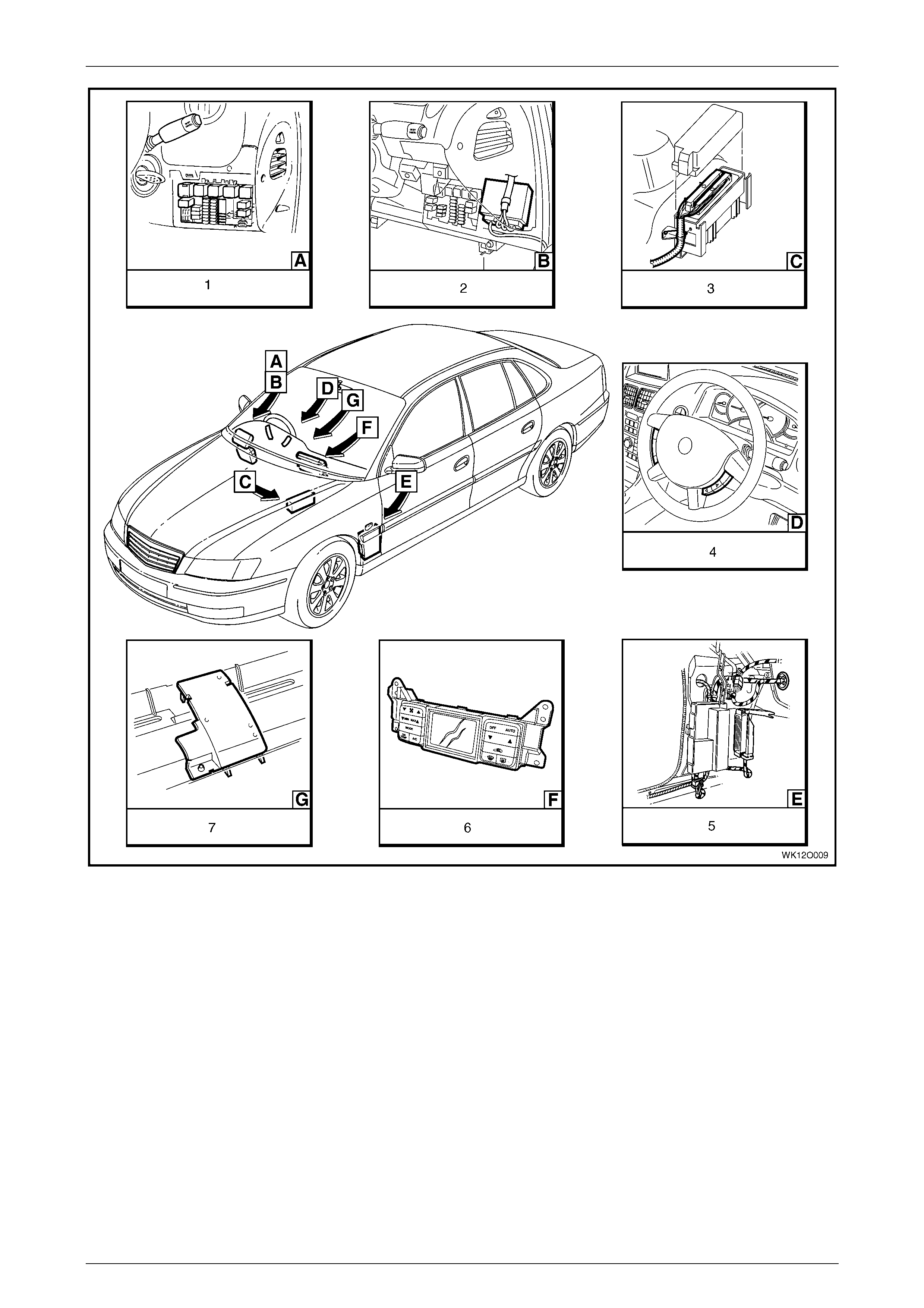
Figure 2 – 2
Legend
1 Relays & Fuses – Instrument P anel
2 Body Control Module
3 Powertrain Control Module – Gen III V8 Engine
4 Steering Wheel Radio & CD Player Control s
5 Powertrain Interface Module (PIM) – GEN III V8 Engine
6 Climate Control Module
7 Ambient Light Sensor
Precautions Page 2–8
Page 2–8
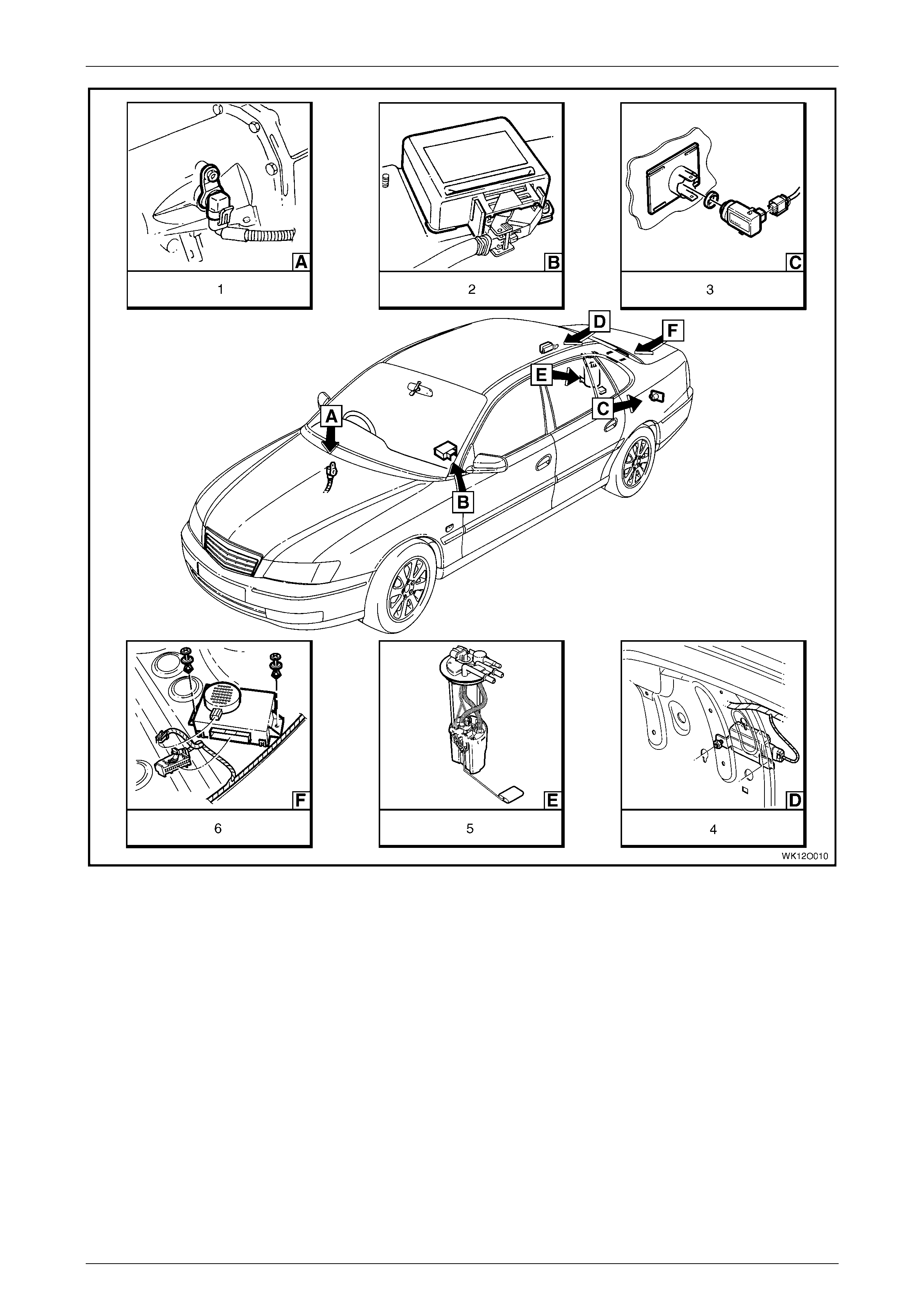
Figure 2 – 3
Legend
1 Vehicle Speed Sensor – Automatic Transmission
2 Sensing & Diagnostic Module – Occupant Protection System
3 Rear Object Sensor Assembl y
4 Fuel Pump Control Module – V6 Supercharged Engine
5 Modular Fuel Pump & Sender Assembly
6 Rear Object Sensor Control Module

Precautions Page 2–9
Page 2–9
Figure 2 – 4
Legend
1 Rear Speaker Amplifier
2 Radio Assembly
3 Rear Speaker (2 Places)
4 Rear Door Speaker Assembl y (2 Places )
5 Anti-theft Horn
6 Front Door Speaker Assembly (2 Places)
7 DVD Player Assembly
Precautions Page 2–10
Page 2–10
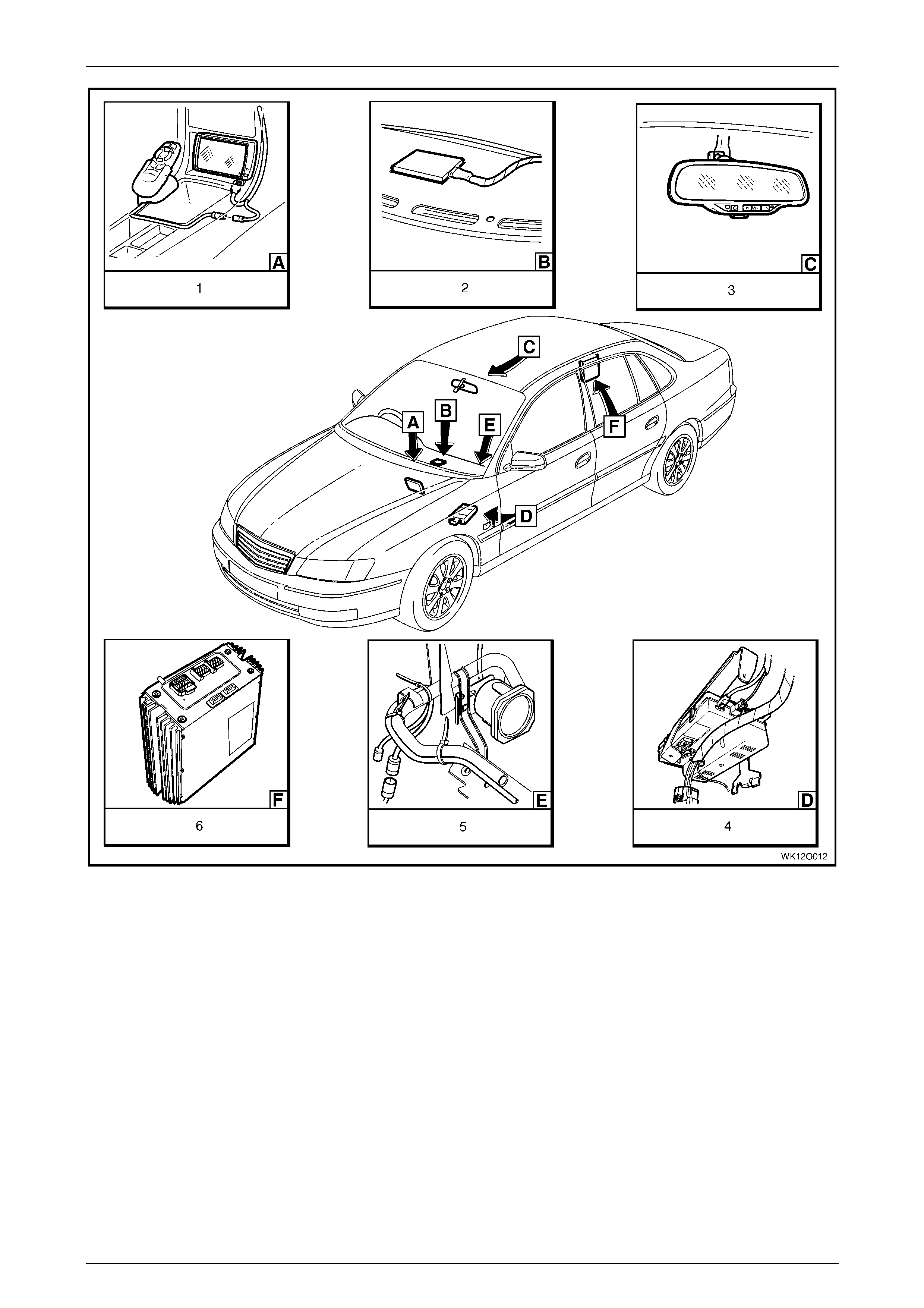
Figure 2 – 5
Legend
1 Navigation S ystem Assembly
2 Telematics Antenna
3 Rear View Mirror Assembly with Telematics
4 Telematics Cont rol Module
5 Navigation S ystem Speaker
6 Radio Speaker Amplifier
Precautions Page 2–11
Page 2–11
3 Cavity Foam
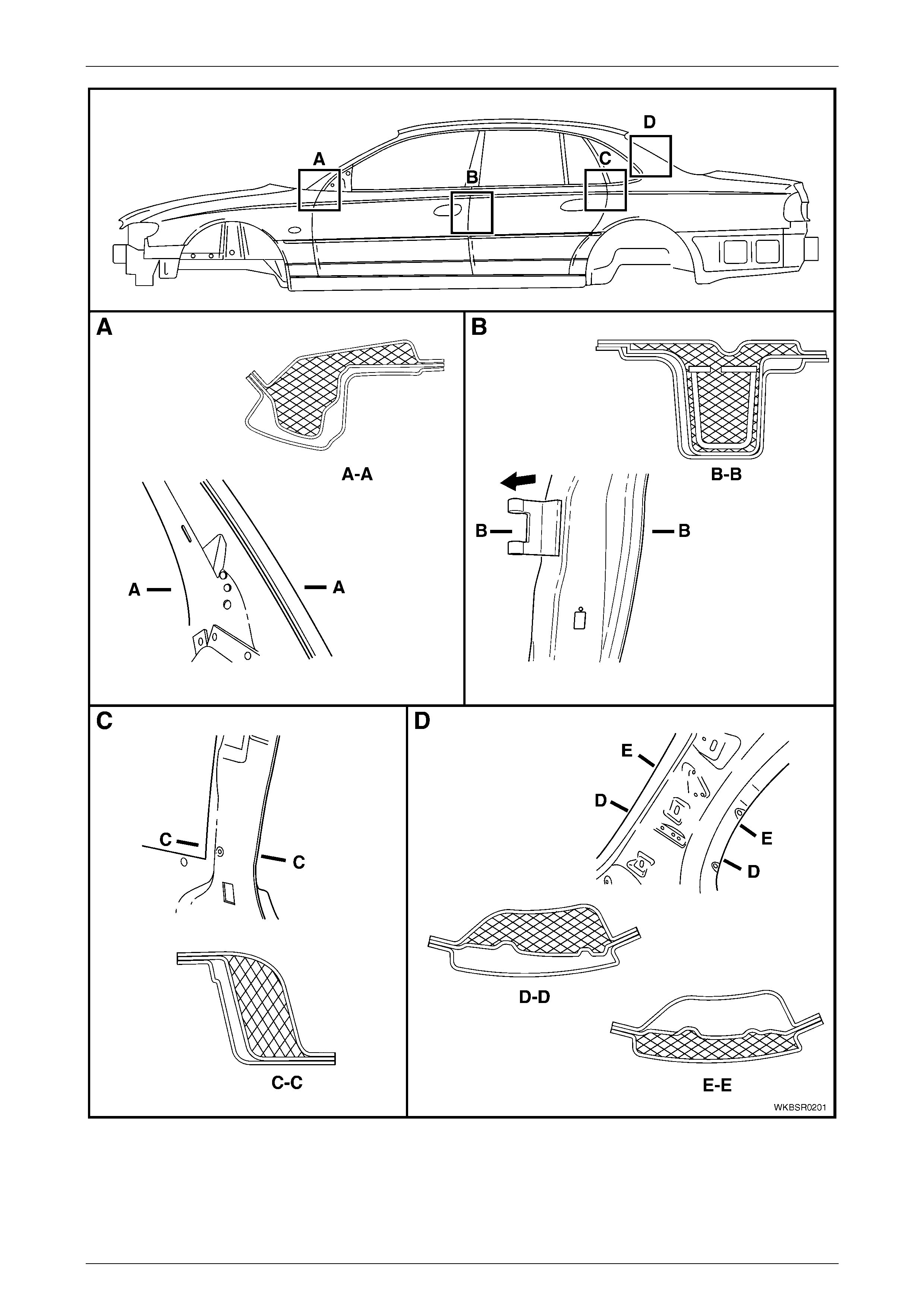
To reduce noise transmittence, cavity foam blocks are placed in the hinge, centre, lock and back lock pillars during
production. This material, when subjected to a temperature of approximately 160°C, expands up to 10 times its original
size to seal the cavity.
The use of this material posses no health and safety risk to a repairer, unless it is heated to temperatures associated
with heating using oxy / acetylene equipment or welding, as toxic fumes will be emitted which must not be inhaled.
Prior to welding or heating in the areas filled with cavity foam, the foam must first be removed - usually by cutting it out
with a knife, refer to Figure 2 – 7.
If a panel or section is replaced or repair work is carried out where the foam is removed, it must be replaced with a
commercially available equivalent, such as those listed, using the following procedure.
Cavity Foam Equivalents
Brand Product
Sista Multi Purpose Foam
Selleys Space Invader
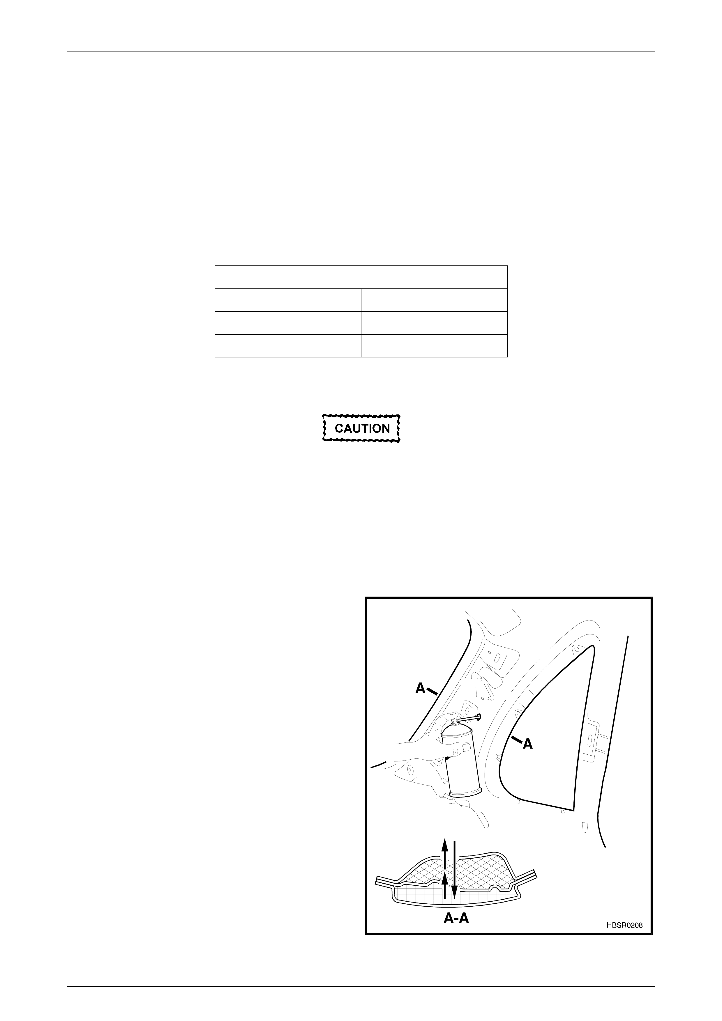
Replace
Take care not to drill into the outer panel.
1 For the hinge, centre and lock pillar, drill a hole in the quarter panel inner assembly at the section areas, refer to
Figure 2 – 7, as required. The hole size should be similar to the diameter of the nozzle supplied with the
replacement foa m.
2 Insert the nozzle into the drilled hole and spray foam into the cavity for several seconds to fill the area to a height of
approximately 50 mm.
3 For the back lock pillar, two cavity blocks are installed, refer to D, Figure 2 – 7. Drill a hole in the quarter panel inner
assembly at Section D-D and carefully continue drilling a further hole through the back lock pillar reinforcement.
4 Insert the nozzle into the drilled hole through the
quarter panel inner assembly and back lock pillar
reinforcement and spray foam into the cavity between
the outer panel and back lock pillar reinforcement for
several seconds to a height of approximately 50 mm.
5 Retract the nozzle into the cavity between the back
lock pillar reinforcement and quarter panel inner
assembly and spray foam to fill this cavity for several
seconds to a height of approximately 50 mm.
Figure 2 – 6
Precautions Page 2–12
Page 2–12
Figure 2 – 7