
Body Const ruct i on Page 3–1
Page 3–1
Section 3
Body Construction
ATTENTION
Before performing any Service Operation or other procedure described in this Section, refer to Section 00
Warnings, Cautions and Notes for correct workshop practices with regard to safety and/or property damage.
The Structure of the MY 2004 WK Series body
shell has been developed using complex
design and development techniques. In
addition to meeting all required standards, the
vehicle body is also a critical part of the
overall safety systems. It is therefore
imperative the repair procedures described
here are adhered to during all vehicle body
repairs.
1 General Information............................................................................................................................... 2
2 Body Structure Panels .......................................................................................................................... 3
2.1 Front End and Underbody.....................................................................................................................................4
2.2 Upperbody Structure – Excluding Roof...............................................................................................................6
2.3 Roof Structure........................................................................................................................................................8
2.4 Body Assembly ......................................................................................................................................................9
3 Body Dimensions ................................................................................................................ ................ 11
3.1 Underbody Dimensions – Projected...................................................................................................................11
3.2 Upperbody Dimensions – Actual........................................................................................................................13
Front......................................................................................................................................................................13
Side and Interior...................................................................................................................................................14
Rear.......................................................................................................................................................................15
4 Body Margins....................................................................................................................................... 16
5 Body Sealing, Adhesives And Deadeners ........................................................................................19
5.1 Body Sealing.........................................................................................................................................................19
Weld Through Primer (Item 1).............................................................................................................................19
Acrylic Spot Weld Sealer (Item 2) .......................................................................................................................19
Joint Sealer (Item 3).............................................................................................................................................19
Hand Putty (Item 4)...............................................................................................................................................19
Adhesive - Anti-Flutter (Item 5)...........................................................................................................................20
Adhesive - Structural (Item 6)..............................................................................................................................20
Spray-on Deadener (Item 7).................................................................................................................................20
Deadener Panels ..................................................................................................................................................20
5.2 Acrylic Spot Weld Sealer (Item 2) .......................................................................................................................21
5.3 Joint Sealer (Item 3).............................................................................................................................................23
5.4 Adhesive – Anti-Flutter (Item 5) ..........................................................................................................................29
5.5 Adhesive – Structural (Item 6).............................................................................................................................31
5.6 Spray-on Deadener ..............................................................................................................................................32
5.7 Deadener Panels & Insulators.............................................................................................................................33
6 Cavity Wax............................................................................................................................................ 36

Body Const ruct i on Page 3–2
Page 3–2
1 General Information
With the following exceptions, MY 2004 WK Series body construction information carries over from MY 2003 VY Series
vehicles. For information not contained within this Section, refer to Section 3, Body Construction, in the MY 2003 VY and
V2 Series Service Information Supplement, Body Structure Repair.
• Body structure panels
• Body dimensions
• Body margins
• Body sealing, adhesives and deadeners
• Cavity wax
This Section contains body construction information specific to MY 2004 WK Series vehicles.
It describes the body structure as a whole and provides a detailed breakdown of the body structure components, key
body dimensional measurements and body margin tolerances.
The various sealers and adhesives used throughout the body are also described, as it is imperative that only the correct
materials are used for repairs.
The correct cavity wax, deadeners and paint refinishing techniques are also imperative if the vehicle is to be returned to
its original condition.
When replacing or repairing a part or sub-assembly, care must be taken to ensure that correct alignment and strength of
unit as a whole is maintained. In some instances, major damage to the body or frame can be repaired more effectively
and economically by replacing a part or sub-assembly with a new one, rather than repairing the damaged part.
A sunroof option is available that is fitted on the production line. To cater for this option, a new roof structure has been
introduced which features a housing assembly in place of the roof bow panel. A stainless steel front drain tube is also
fitted within the hinge pillar cavity which effects the service procedures for the hinge pillar, refer to Section 7 Body Side
and Section 9 Roof.

Body Const ruct i on Page 3–3
Page 3–3
2 Body Structure Panels
The following tables and illustrations describe the body structure assemblies and panels that are available for service
replacement.
NOTE
Always refer to your authorised Retailer for spare
parts availabil ity config urati on s .
Body Const ruct i on Page 3–4
Page 3–4
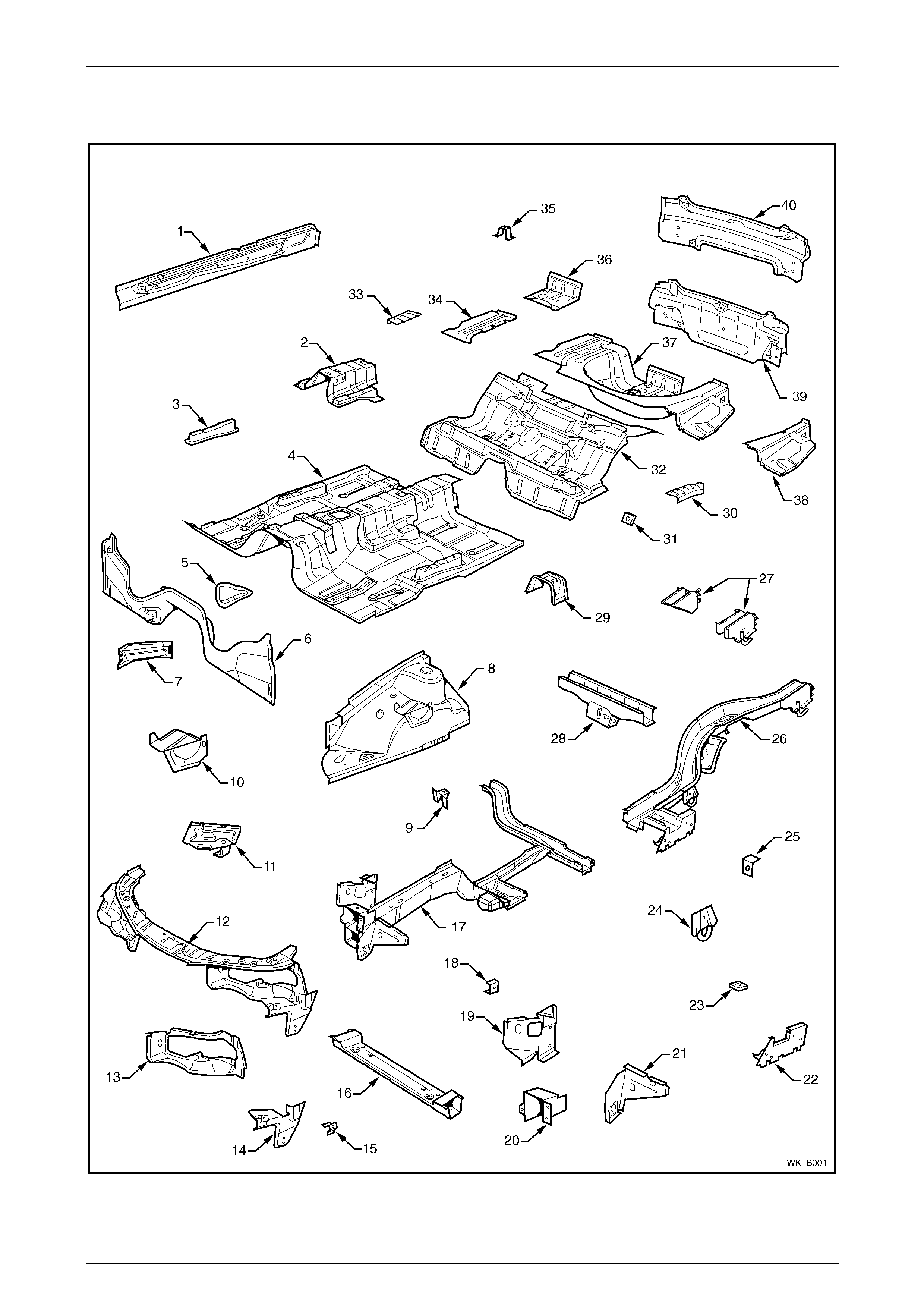
2.1 Front End and Underbody
Figure 3 – 1

Body Const ruct i on Page 3–5
Page 3–5
Legend
1 Inner Rocker P anel Assembl y
2 Seat Inner Bracket Assembly
3 Seat Outer Bracket Assembly
4 Front Floor Panel Assembly
5 Transmission Support Bracket
6 Front Floor Panel Extension
7 Front Side Rail Brace
8 Front wheelhouse panel Assembly
9 Forn bracket Assembly
10 Abs modulator bracket Assembly
11 Battery tray Assembly
12 Front End Panel Assembly
13 Headlamp Panel
14 Headlamp And Front Fascia Mount Bracket
15 Fender Front Lower Bracket
16 Radiator Lower Support Assembly
17 Front Side Rail Assembly
18 Radiator Side Mounting Bracket
19 Front Wheelhouse Bracket Assembly
20 Front Bumper Impact Bar Bracket
21 Front Wheelhouse Panel Bracket
22 Rear Floor Panel Outer Extension
23 Rear Suspension Support Mount Plate
24 Rear Tie Down Assembly
25 Rear Brake Hose Bracket
26 Rear Side Rail Assembly
27 Rear Bumper Impact Bar Brace Assembly, LH / RH
28 Crossmember Assembl y No. 2
29 Propeller Shaft Hanger Assembly
30 Rear Floor Panel Reinforcement, LH
31 Rear Seat Belt Anchor Plate Assembly
32 Rear Floor Panel Assembly
33 Rear Floor Panel Reinforcement, RH
34 Rear Compartment Floor Panel Outer Extension, RH
35 Spare Wheel Anchor Plate Assembly
36 Fuel Tank Support Reinforcement Assembly
37 Rear Compartment Floor Panel Assembly
38 Rear Compartment Floor Panel Outer Extension, LH
39 Rear End Panel Assembly
40 Rear End Lower Panel
Body Const ruct i on Page 3–6
Page 3–6
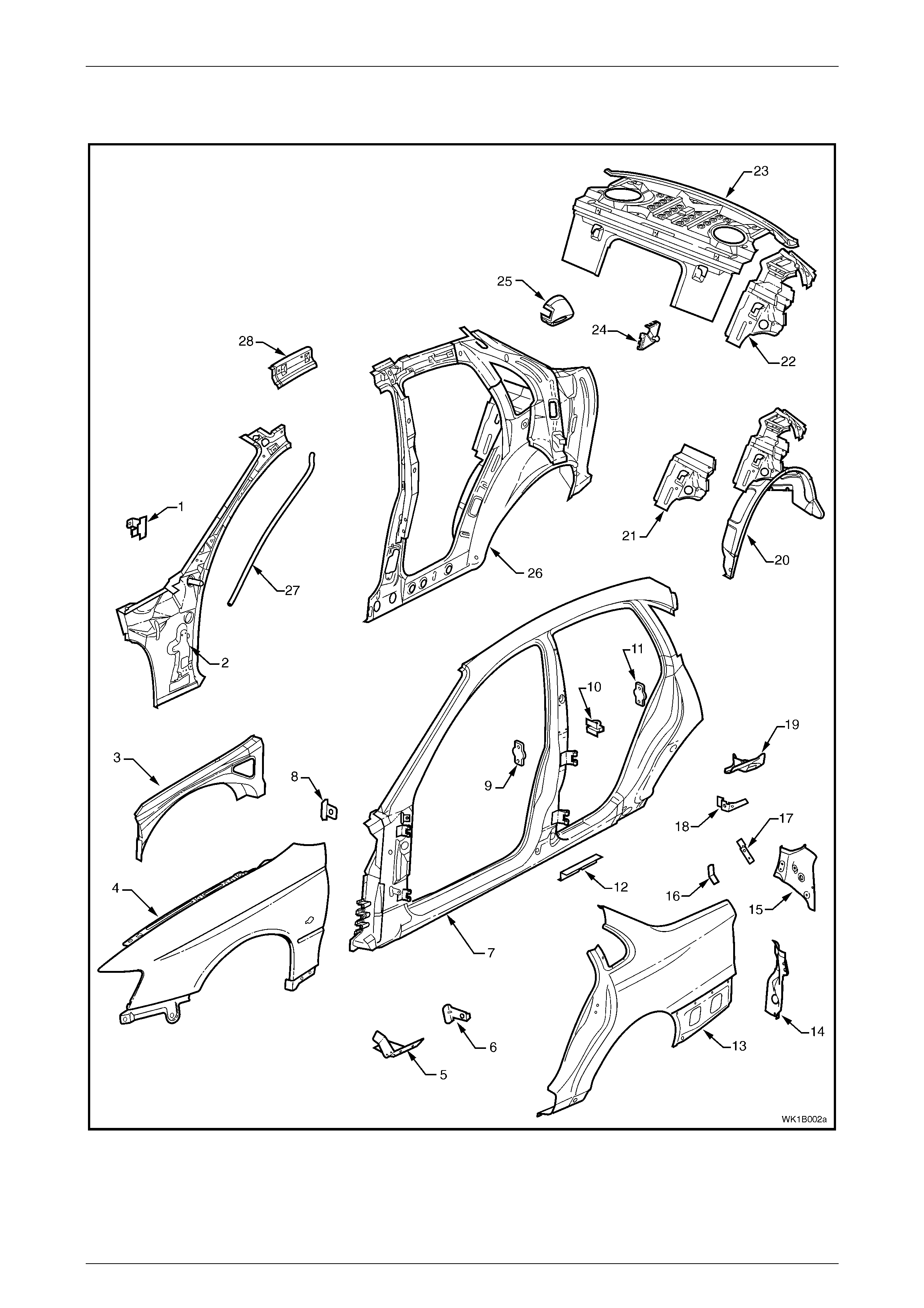
2.2 Upperbody Structure – Excluding Roof
Figure 3 – 2

Body Const ruct i on Page 3–7
Page 3–7
Legend
1 Hinge Pillar Trim Panel Bracket
2 Hinge Pillar Inner Panel Assembly
3 Front Wheelhouse Panel Upper Side Rail
4 Front Fender
5 Fender Lower Rear Bracket
6 Fender Rear Bracket
7 Door Opening Frame Assembly
8 Fender Upper Rear Bracket
9 Front Door Striker Anchor Plate
10 Rear Door Check Link Bracket
11 Rear Door Striker Anchor Plate
12 Underbody Jacking Locator
13 Rear Quarter Panel
14 Quarter Panel Lower Extension
15 Tail Lamp Housing
16 Wiring Harness Bracket
17 Tail Lamp Connector Bracket
18 Rear Compartment Trim Attach Bracket
19 Quarter Panel Upper Extension
20 Rear Wheelhouse Inner Panel Assembly
21 Rear Seat Back Panel Extension
22 Rear Seat Back Panel Extension Assemb l y
23 Rear Window Panel Assembly
24 Rear Compartment Lid Strut Bracket Assem bl y
25 Fuel Filler Pipe Housing
26 Quarter Panel Inner Assembly
27 Sunroof Front Drain Tube
28 Quarter Panel Inner Extension
Body Const ruct i on Page 3–8
Page 3–8
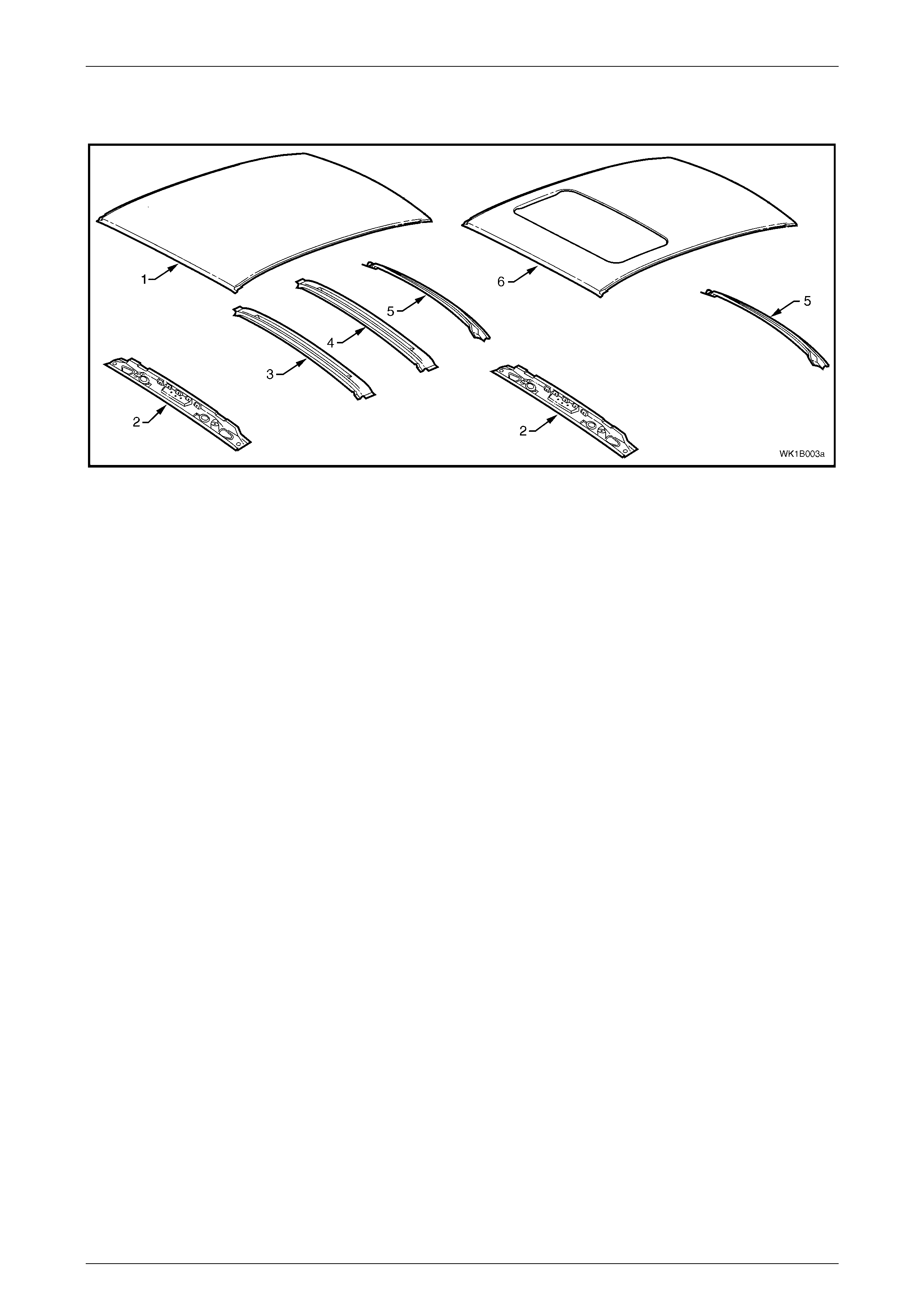
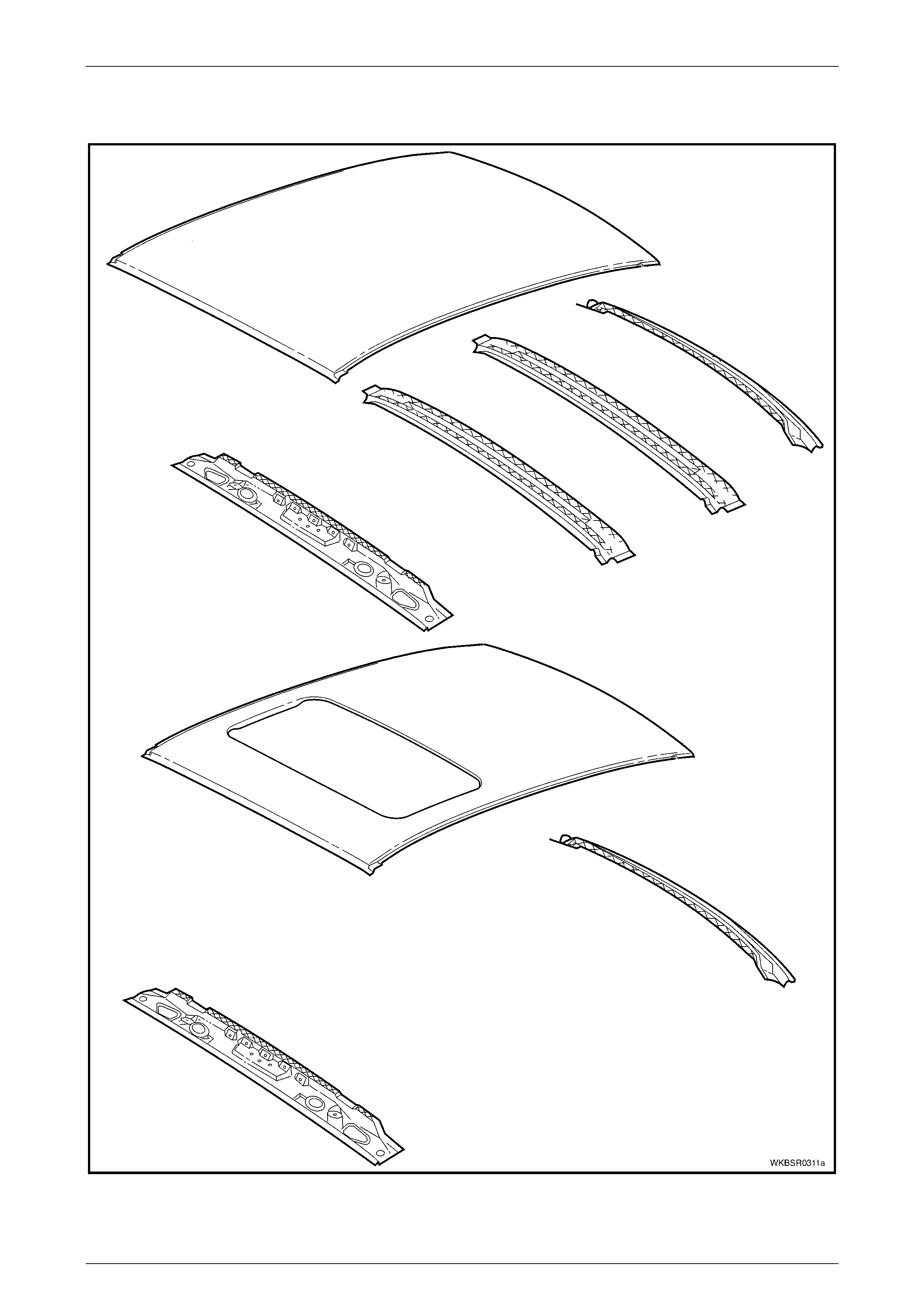
2.3 Roof Structure
Figure 3 – 3
Legend
1 Roof Panel
2 Roof Front Header Panel
3 Roof Bow Panel
4 Roof Bow Panel No. 2
5 Roof Rear Panel
6 Roof Panel Assembly (With Sunroof)
Body Const ruct i on Page 3–9
Page 3–9
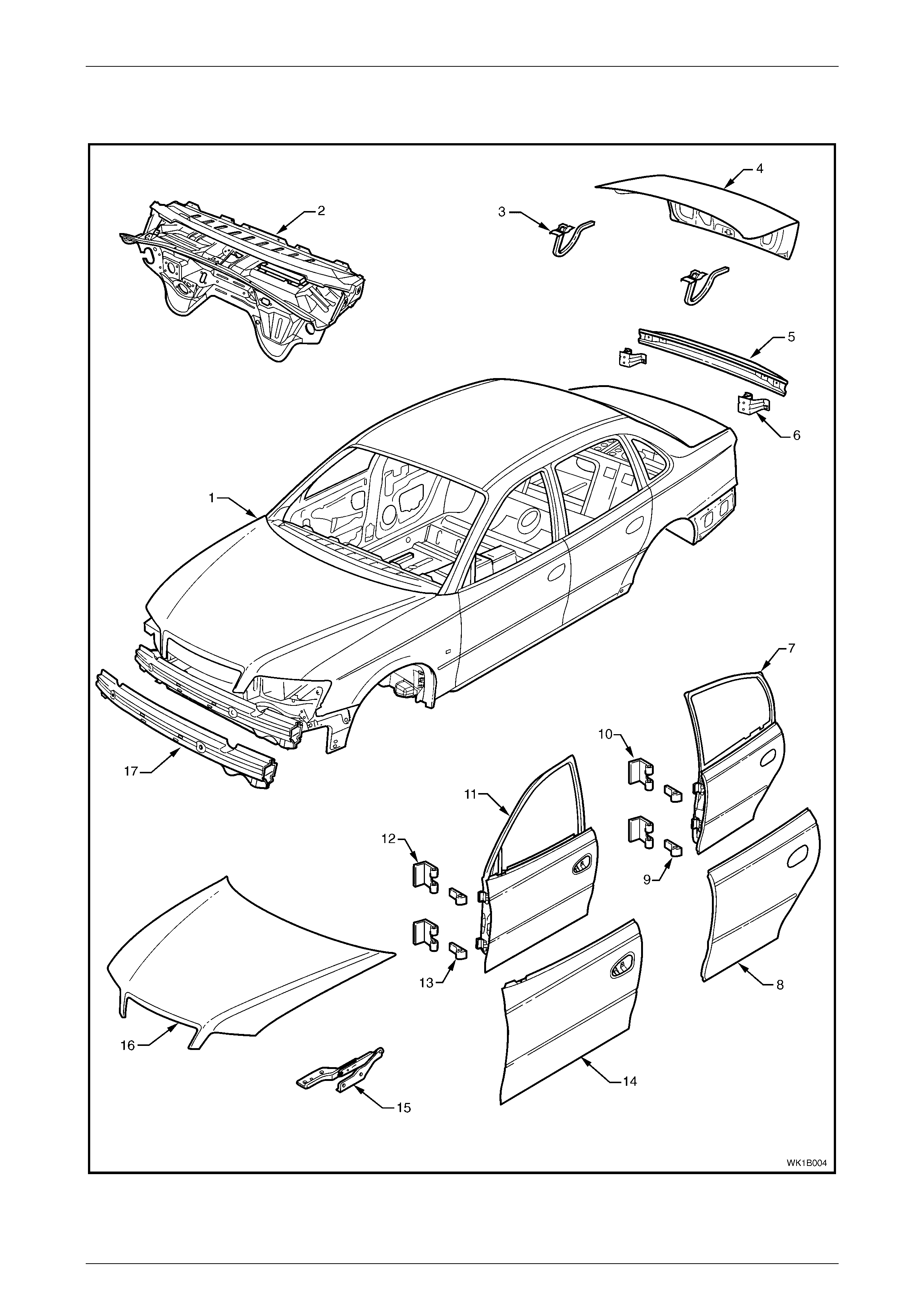
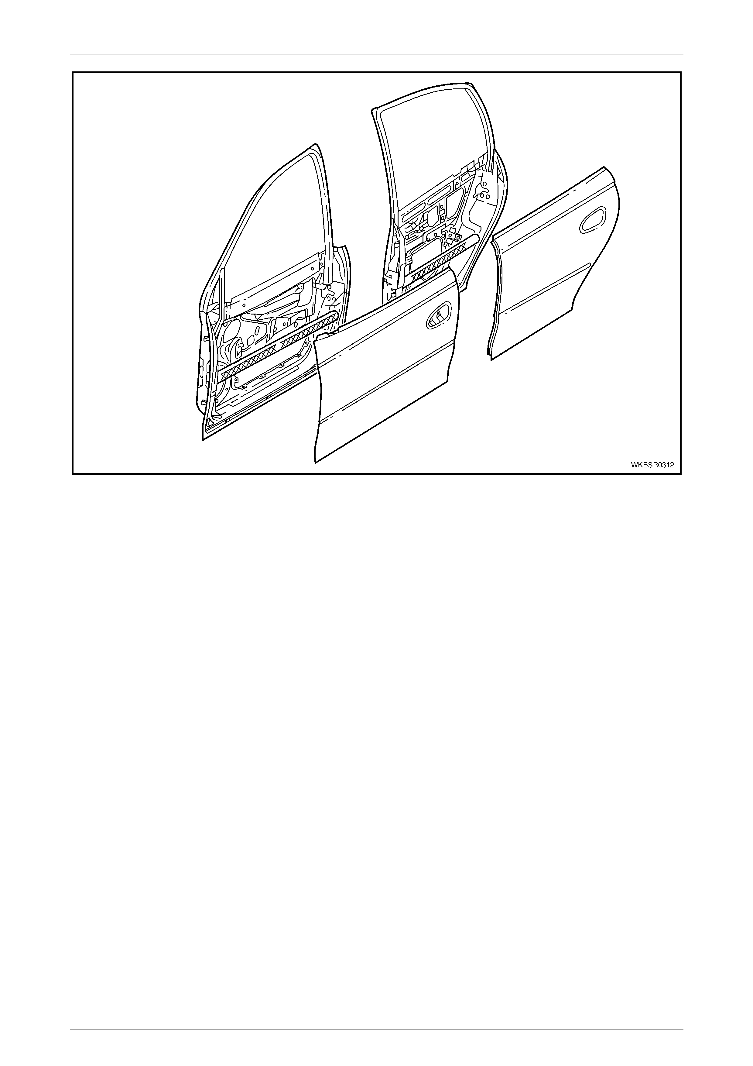
2.4 Body Assembly
Figure 3 – 4

Body Const ruct i on Page 3–10
Page 3–10
Legend
1 Body Assembly
2 Dash Panel Assembly
3 Rear Compartment Lid Hi nge Assembly
4 Rear Compartment Lid Assem bl y
5 Rear Bumper Impact Bar
6 Rear Bumper Impact Bar Bracket Assembly
7 Rear Door Assembl y
8 Rear Door Outer Panel
9 Rear Door Hinge (door side)
10 Rear Door Hinge (body side)
11 Front Door Assembly
12 Front Door Hinge (body side)
13 Front Door Hinge (door side)
14 Front Door Outer Panel
15 Hood Hinge Assembly
16 Hood Assembly
17 Front Bumper Impact Bar Assembly
Body Const ruct i on Page 3–11
Page 3–11
3 Body Dimensions
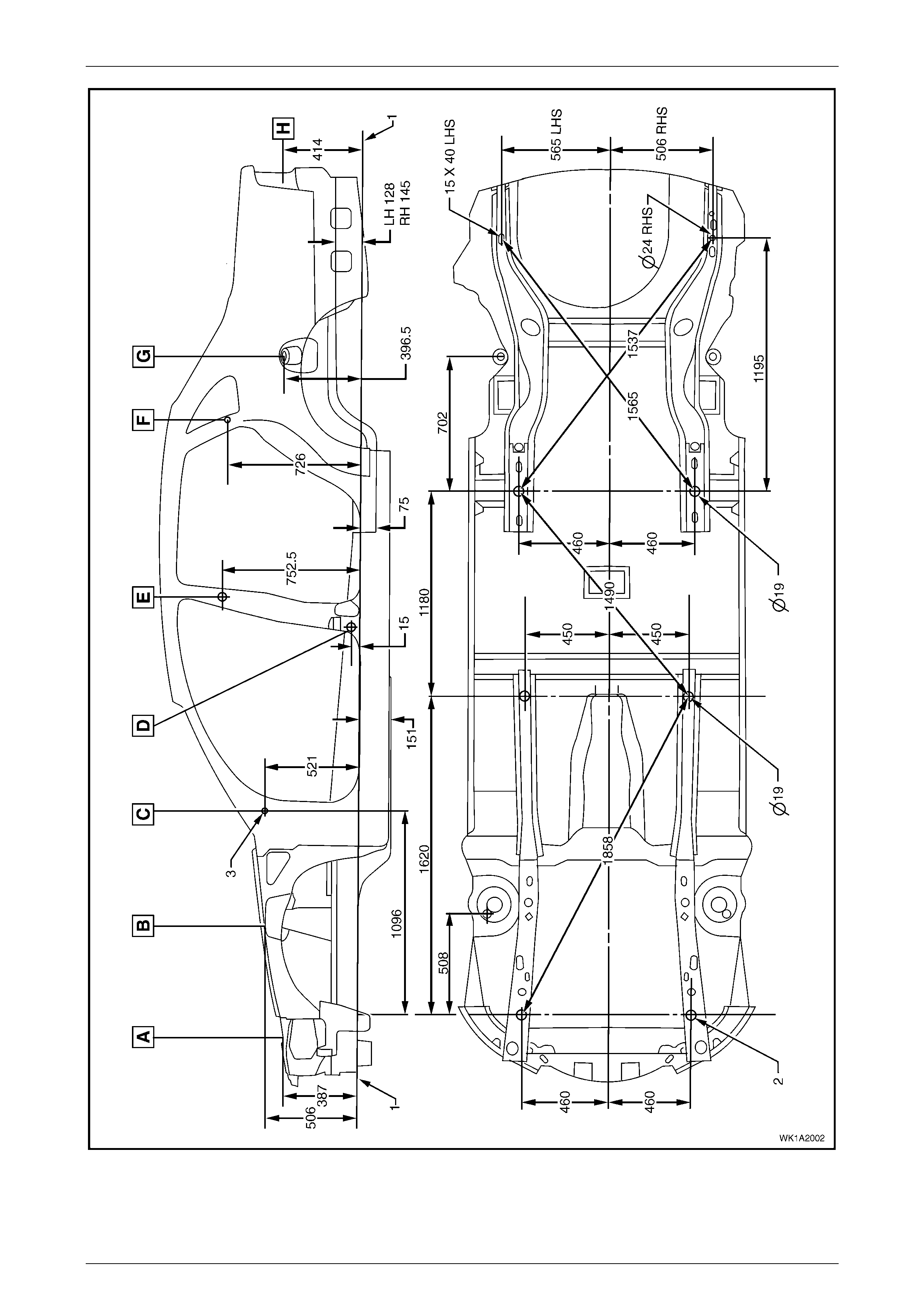
3.1 Underbody Dimensions – Projected
All dimensions are given in mm and are measured from the centre of holes, on the outer side of the metal surface.
The main datum surface (1) is the underside of the front side rail assembly, refer to Figure 3 – 6
The main datum hole (2) is a 19 mm hole on the underside of the front side rail assembly, refer to Figure 3 – 6.
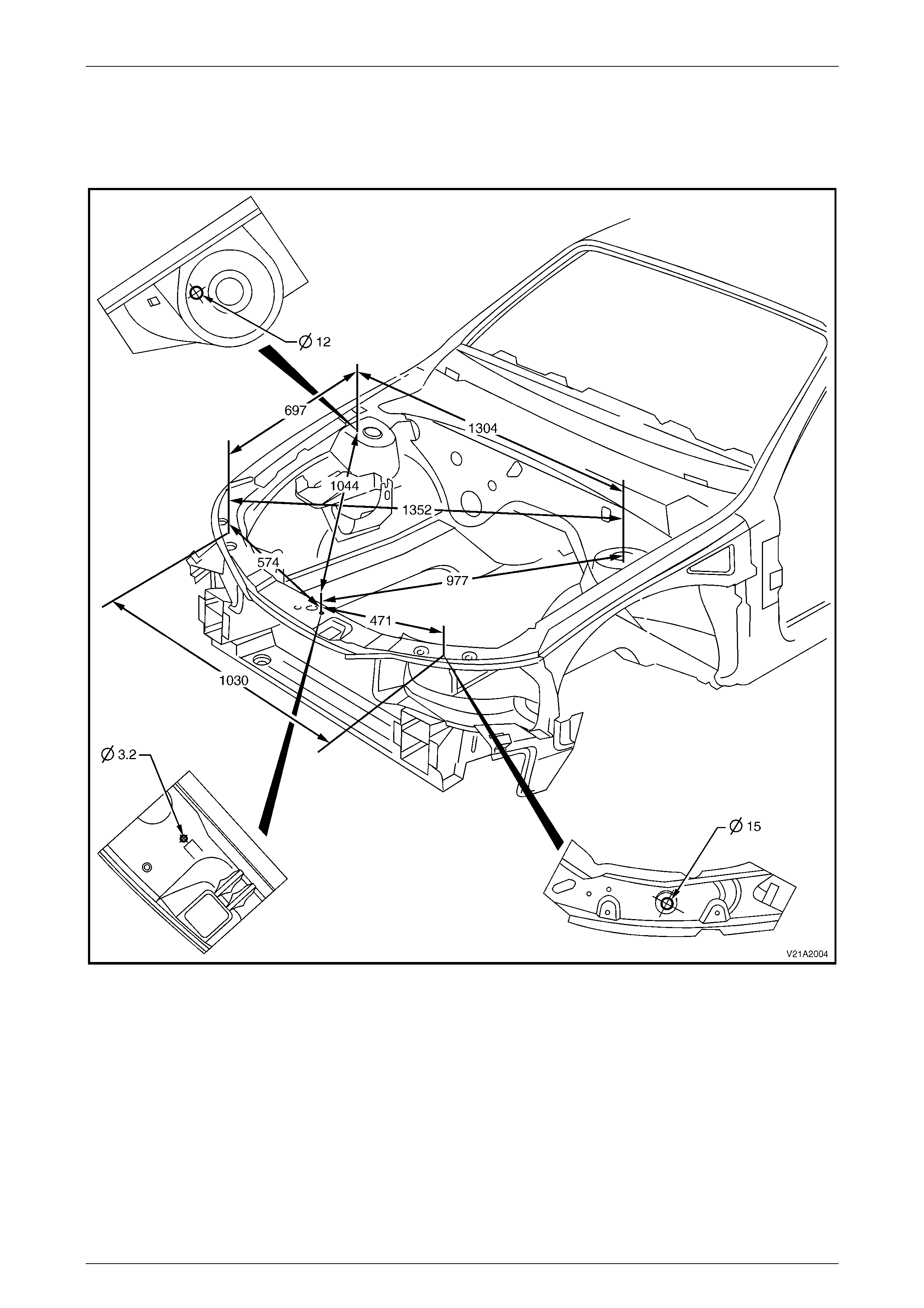
The dash panel assembly attaching hole (3) in Figure 3 – 6 is the datum hole also depicted at View C in Figure 3 – 5.
Figure 3 – 5
Body Const ruct i on Page 3–12
Page 3–12
Figure 3 – 6
Body Const ruct i on Page 3–13
Page 3–13
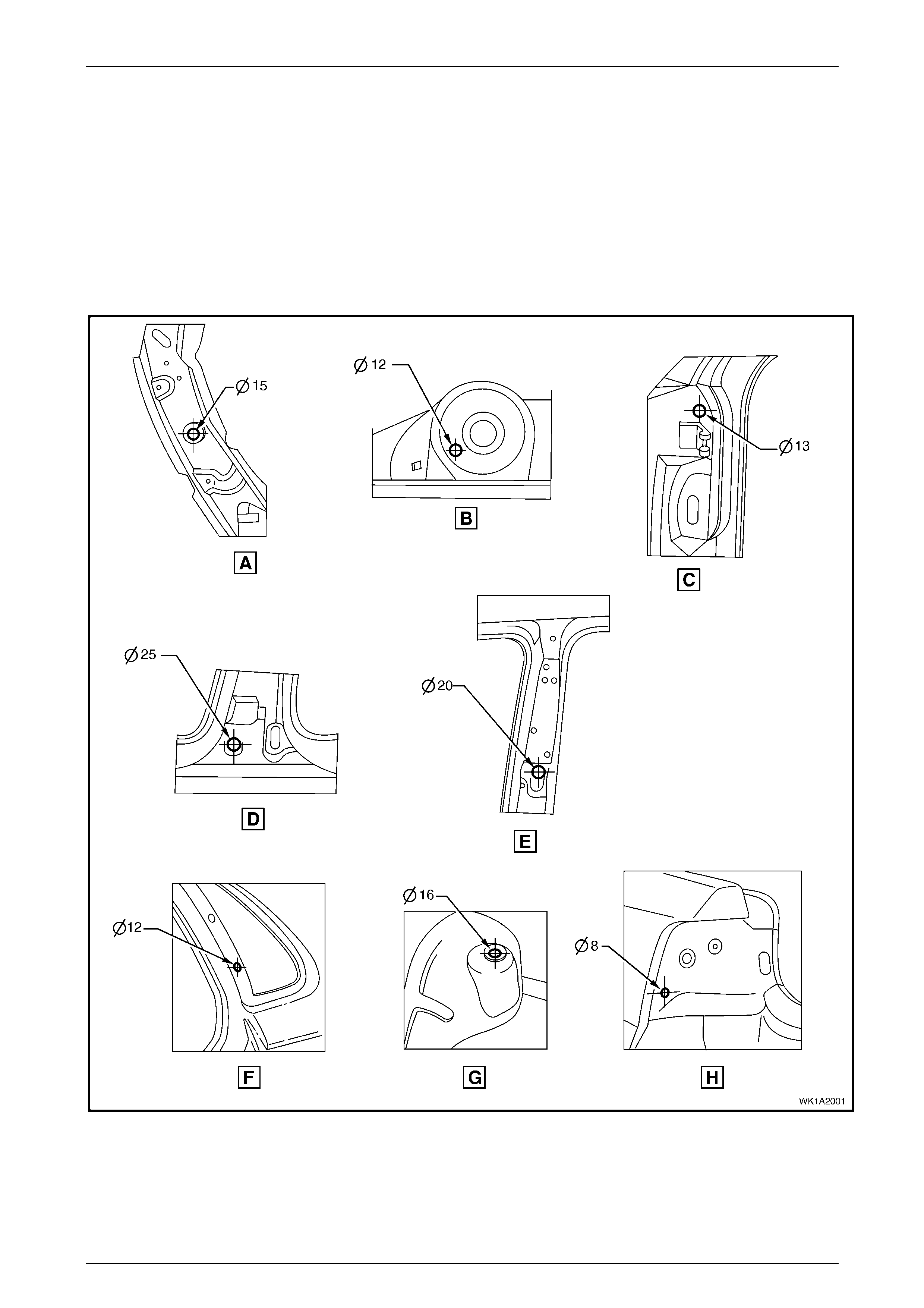
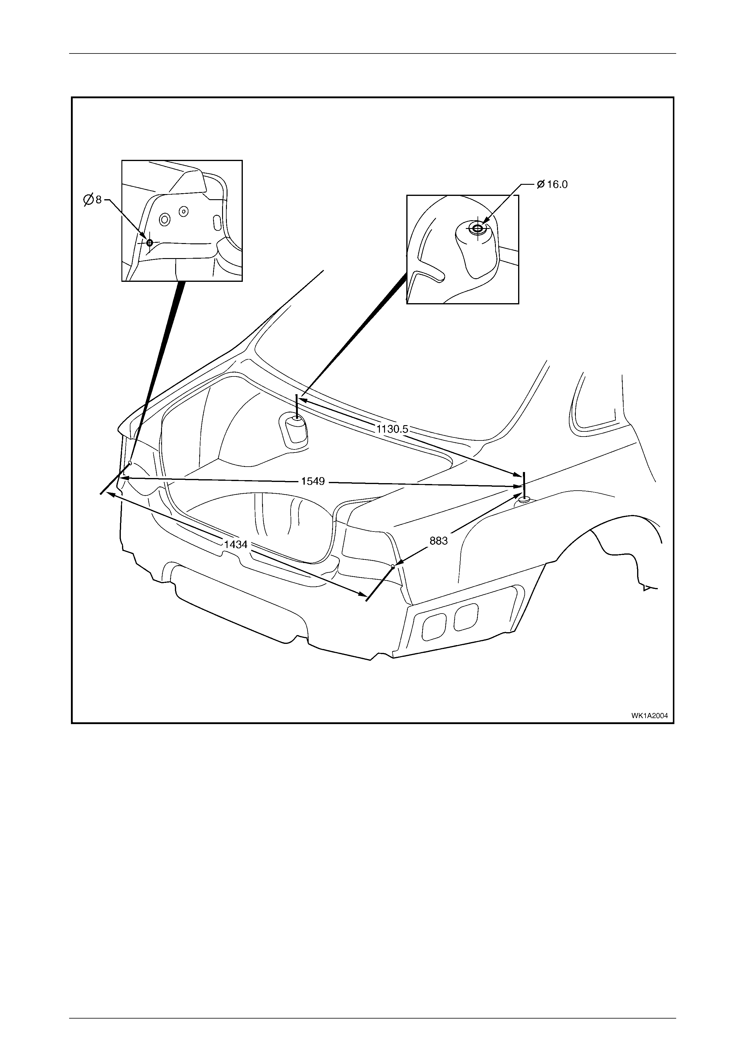
3.2 Upperbody Dimensions – Actual
Front
Figure 3 – 7
Body Const ruct i on Page 3–14
Page 3–14
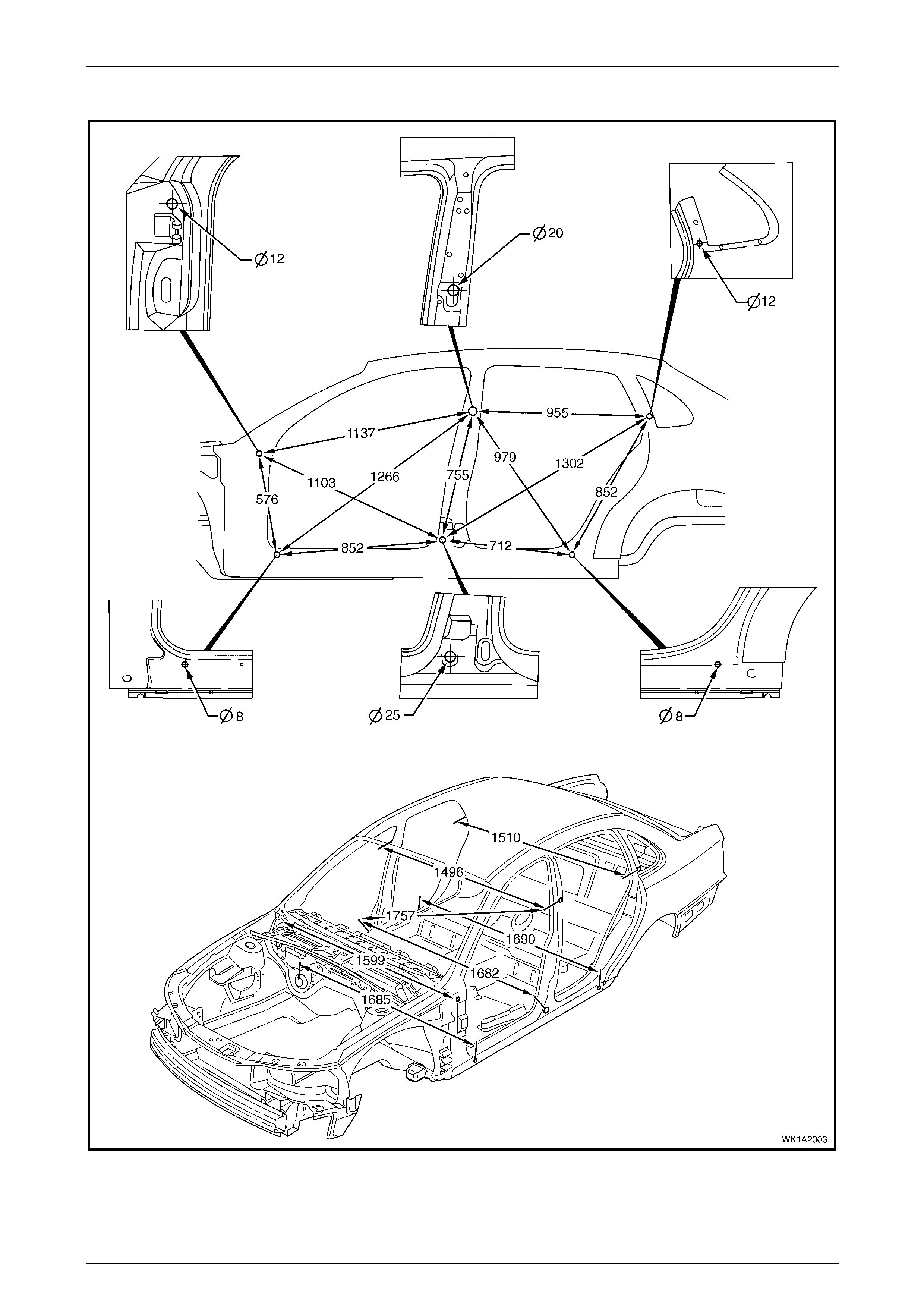
Side and Interior
Figure 3 – 8
Body Const ruct i on Page 3–15
Page 3–15
Rear
Figure 3 – 9
Body Const ruct i on Page 3–16
Page 3–16
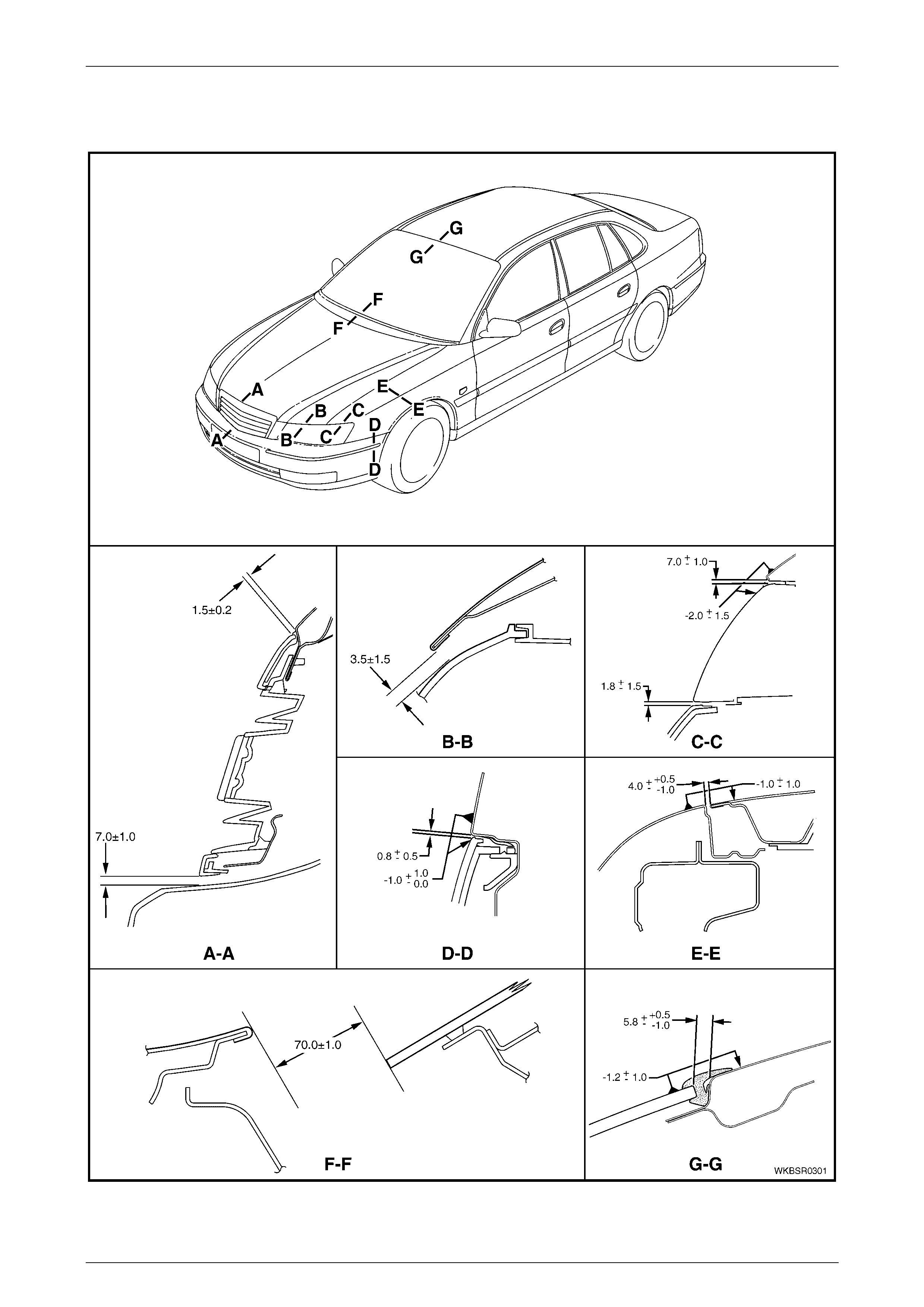
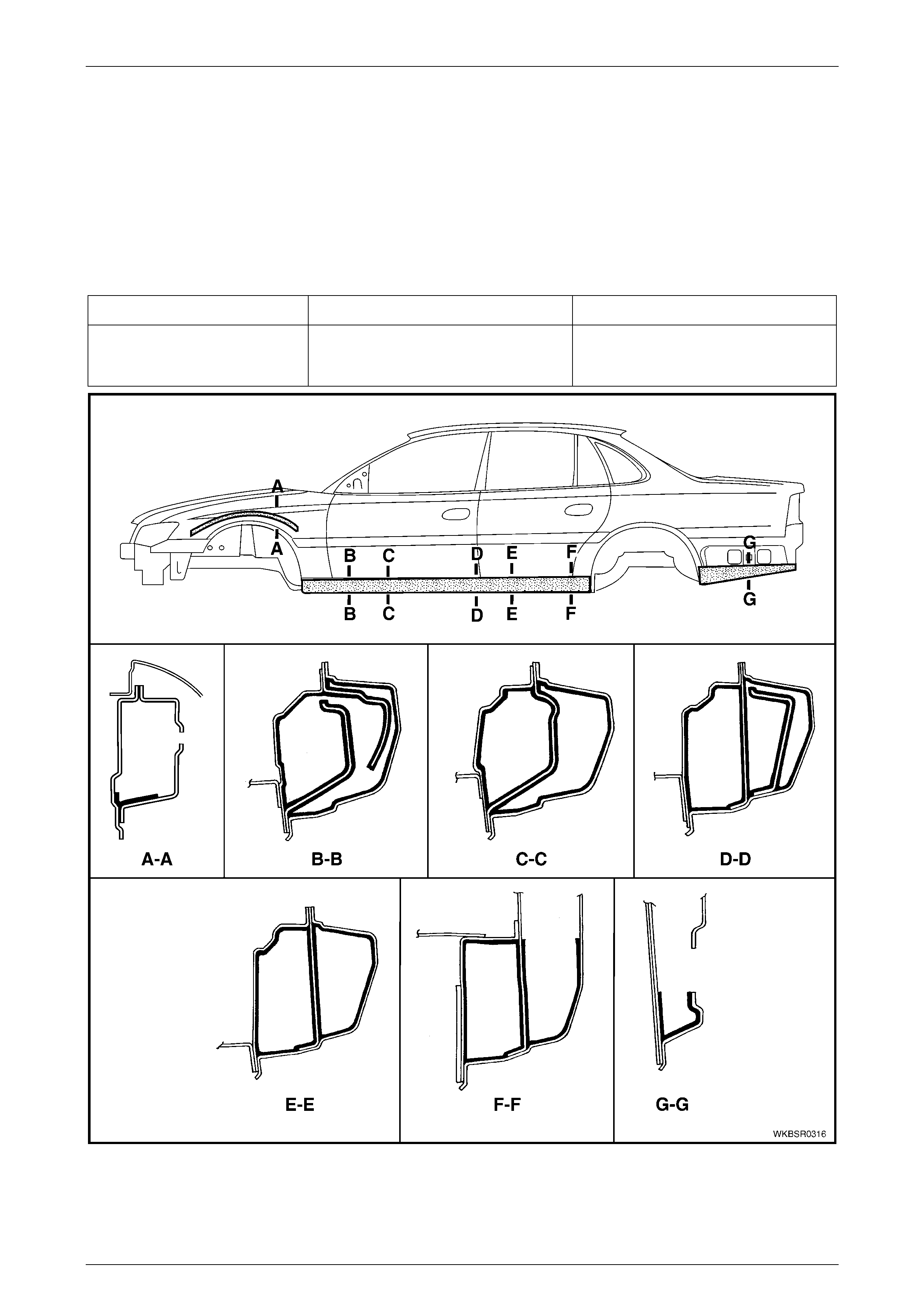
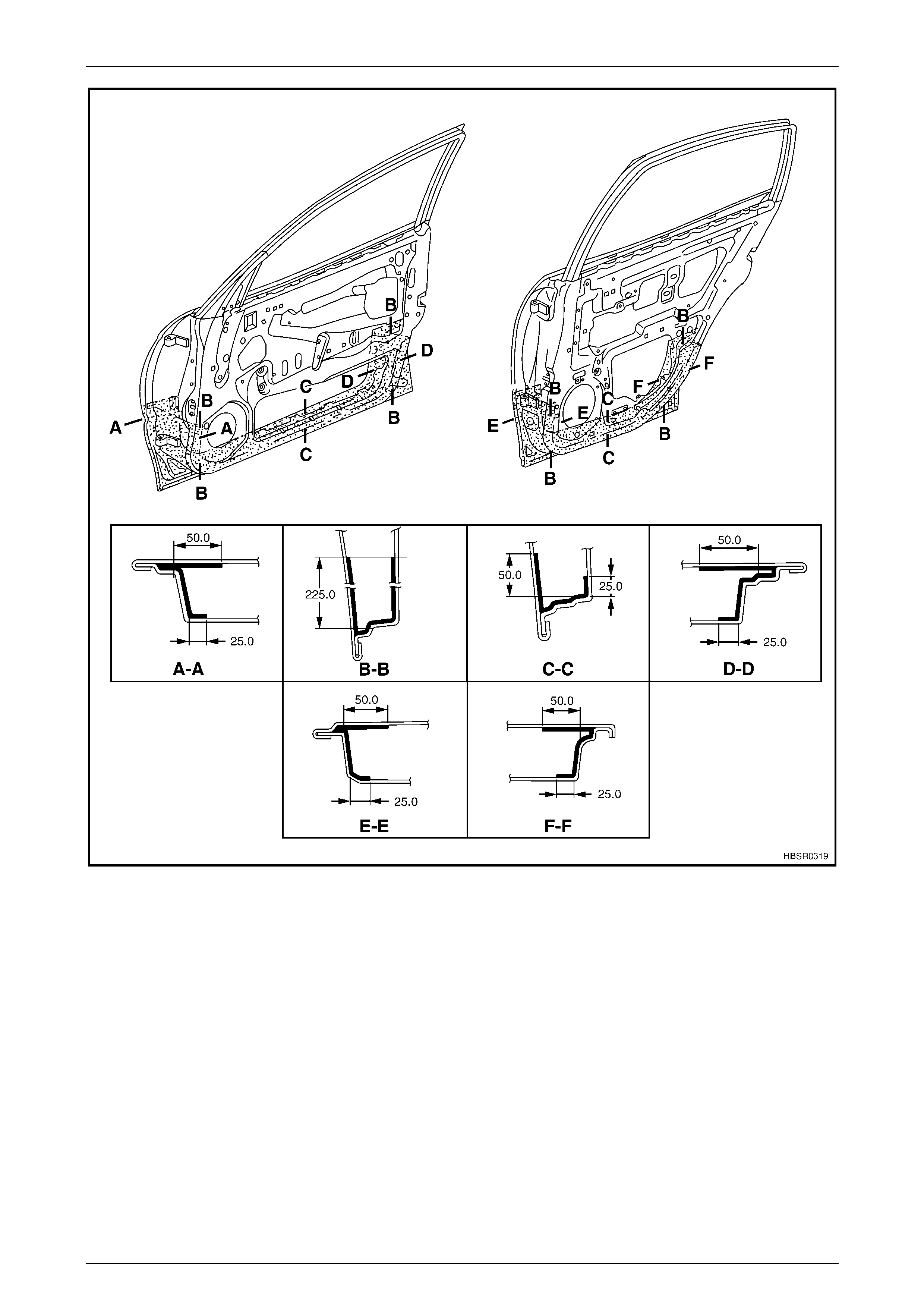
4 Body Margins
Figure 3 – 10
Body Const ruct i on Page 3–17
Page 3–17
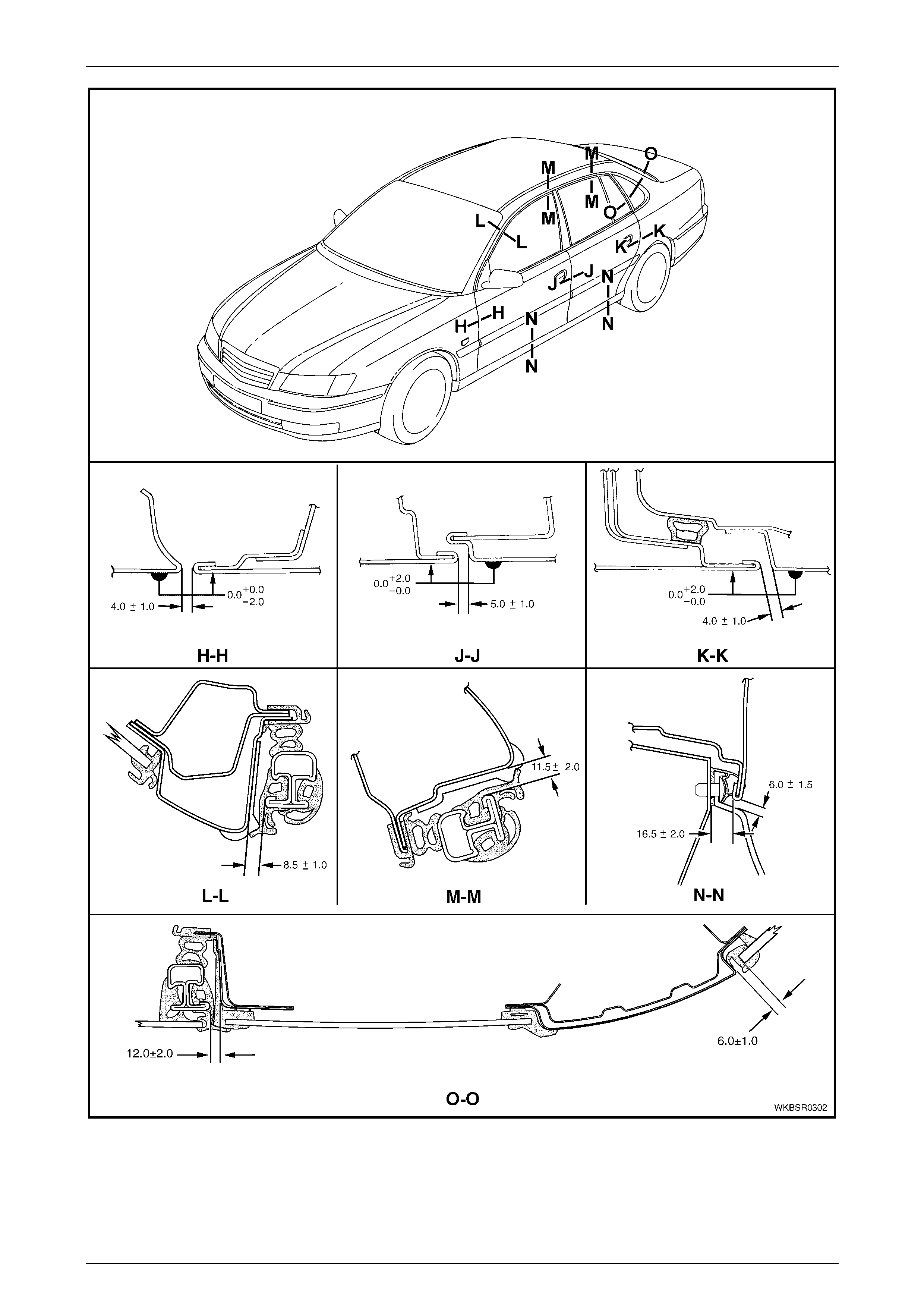
Figure 3 – 11
Body Const ruct i on Page 3–18
Page 3–18
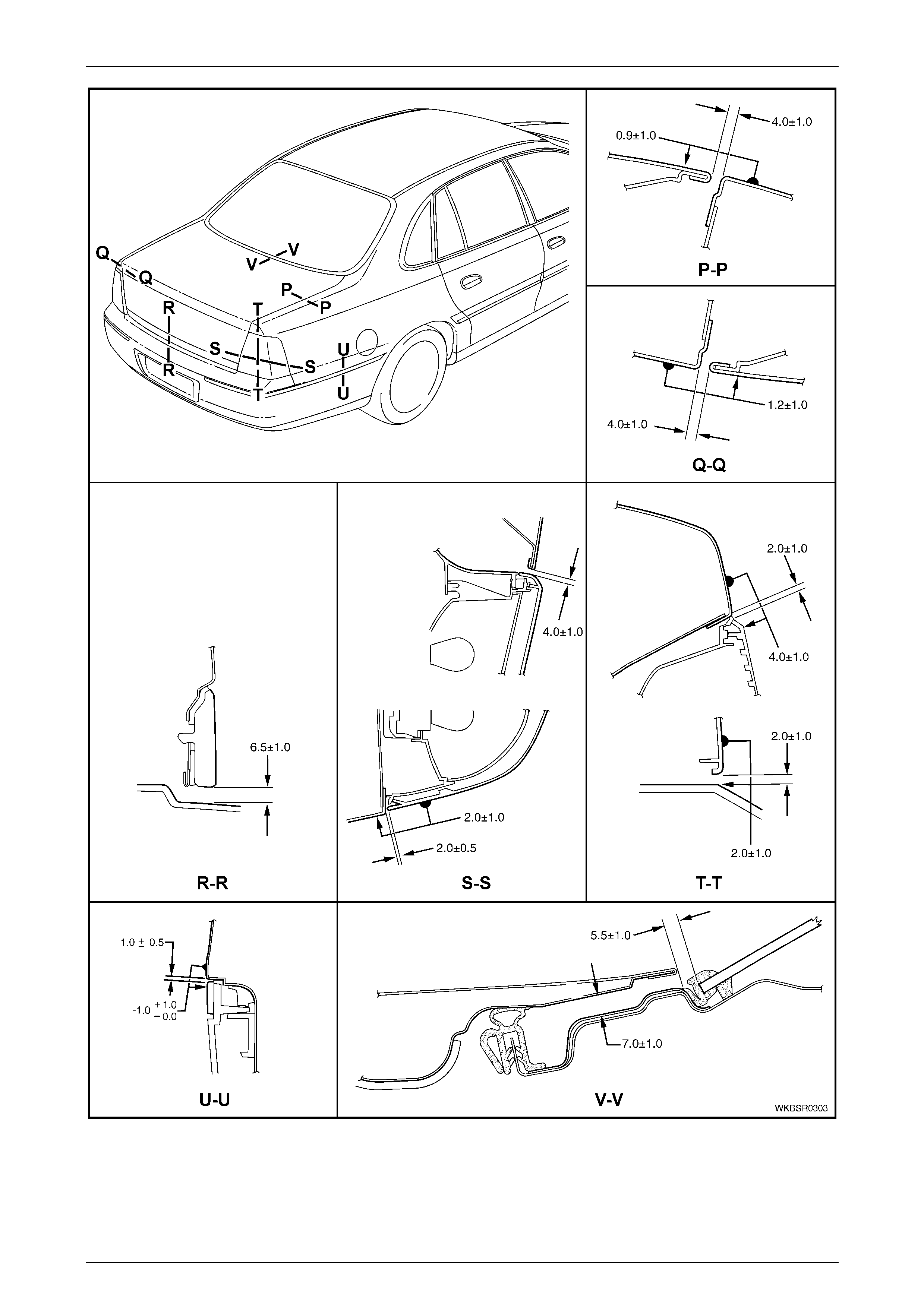
Figure 3 – 12

Body Const ruct i on Page 3–19
Page 3–19
5 Body Sealing, Adhesives And
Deadeners
This Section details the sealers, adhesives and deadeners used in the MY 2004 WK Series Sedan body shell. It is
imperative that the correct materials are used and the directions on the product always be followed.
NOTE
When replacing any sealer, adhesive or
deadener, ensure the finish meets that of the
original applic atio n.
The commercially available products listed
below will meet the required standards. Other
products may be available that meet the
performance characteristics, however before
their use, the product manufacturer should be
contacted to check its suitability.
5.1 Body Sealing
Weld Through Primer (Item 1)
Although not used in manufacture, Weld Through Primer is recommended for all service repair lap and flange joints
where Acrylic Spot Weld Sealer (Item 2) is not used. Weld Through Primer aids in corrosion protection of the joint.
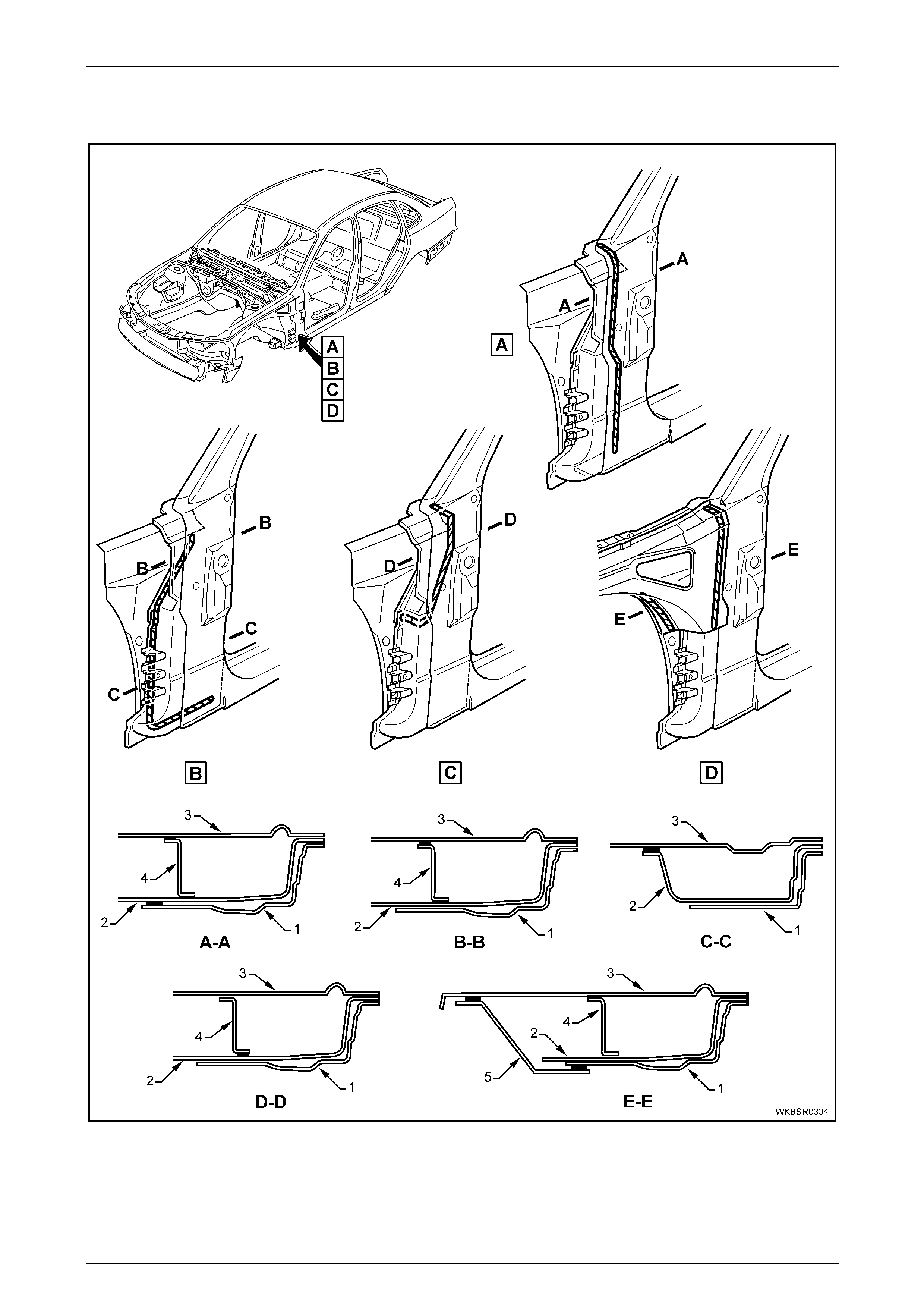
Acrylic Spot Weld Sealer (Item 2)
Used in joints that require sealing additional to Joint Sealer (Item 3). It is applied to the joint flange prior to the mating of
panels. Refer to Figure 3 – 13 & Figure 3 – 14.
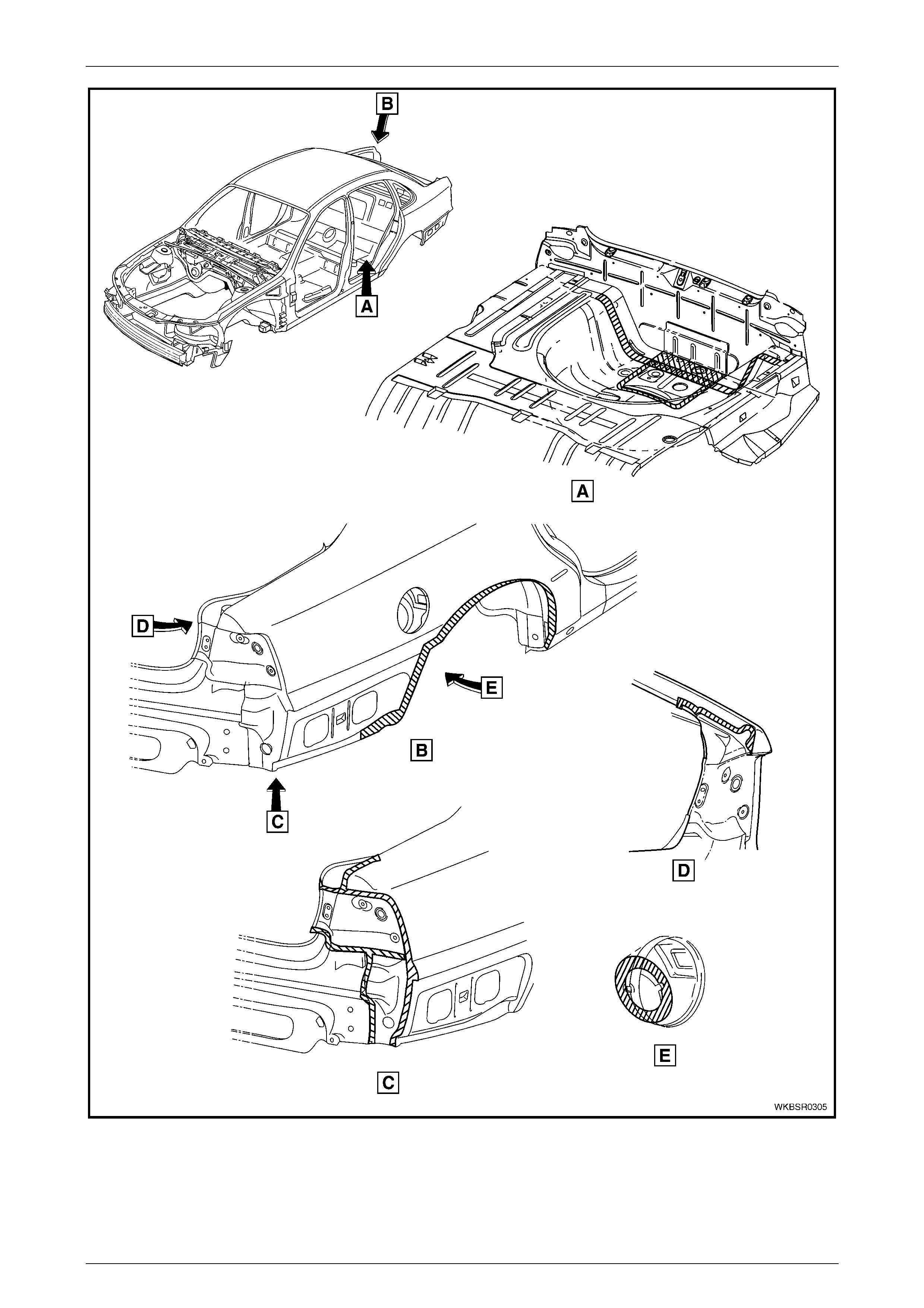
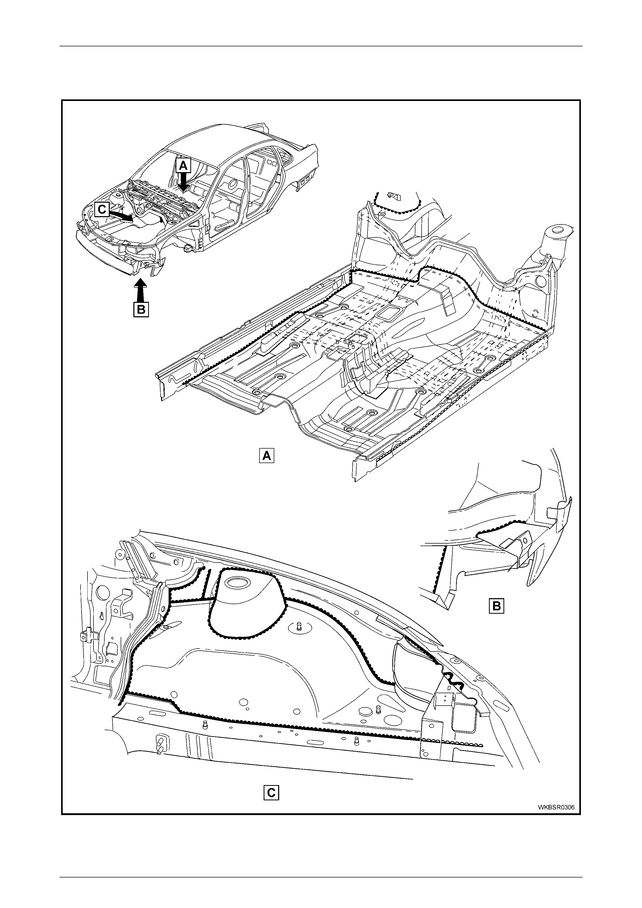
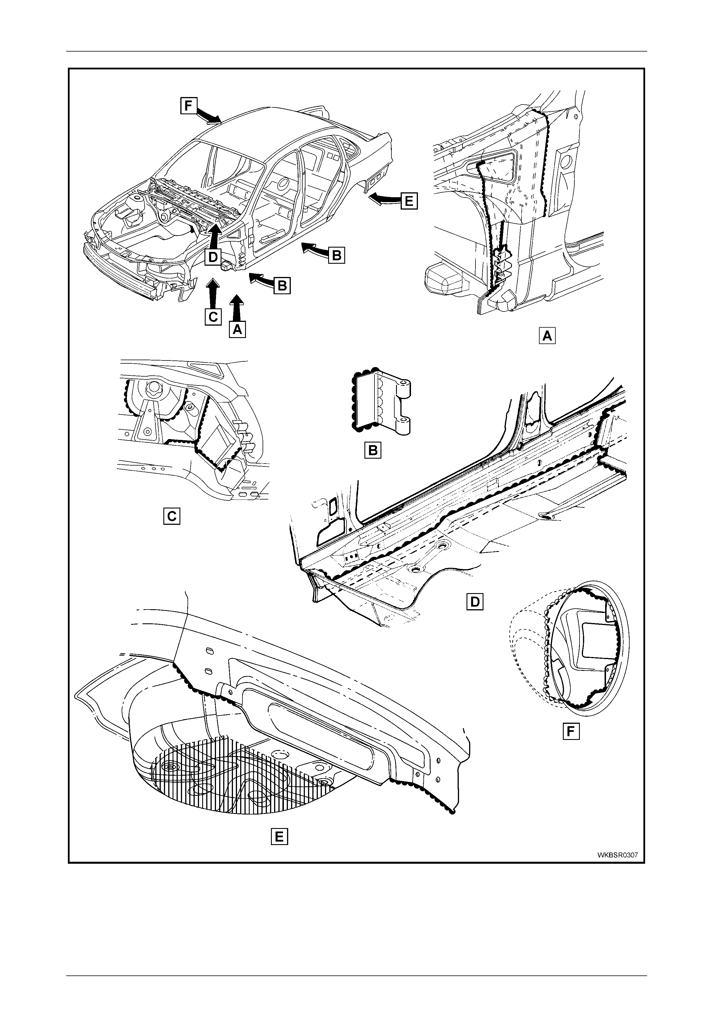
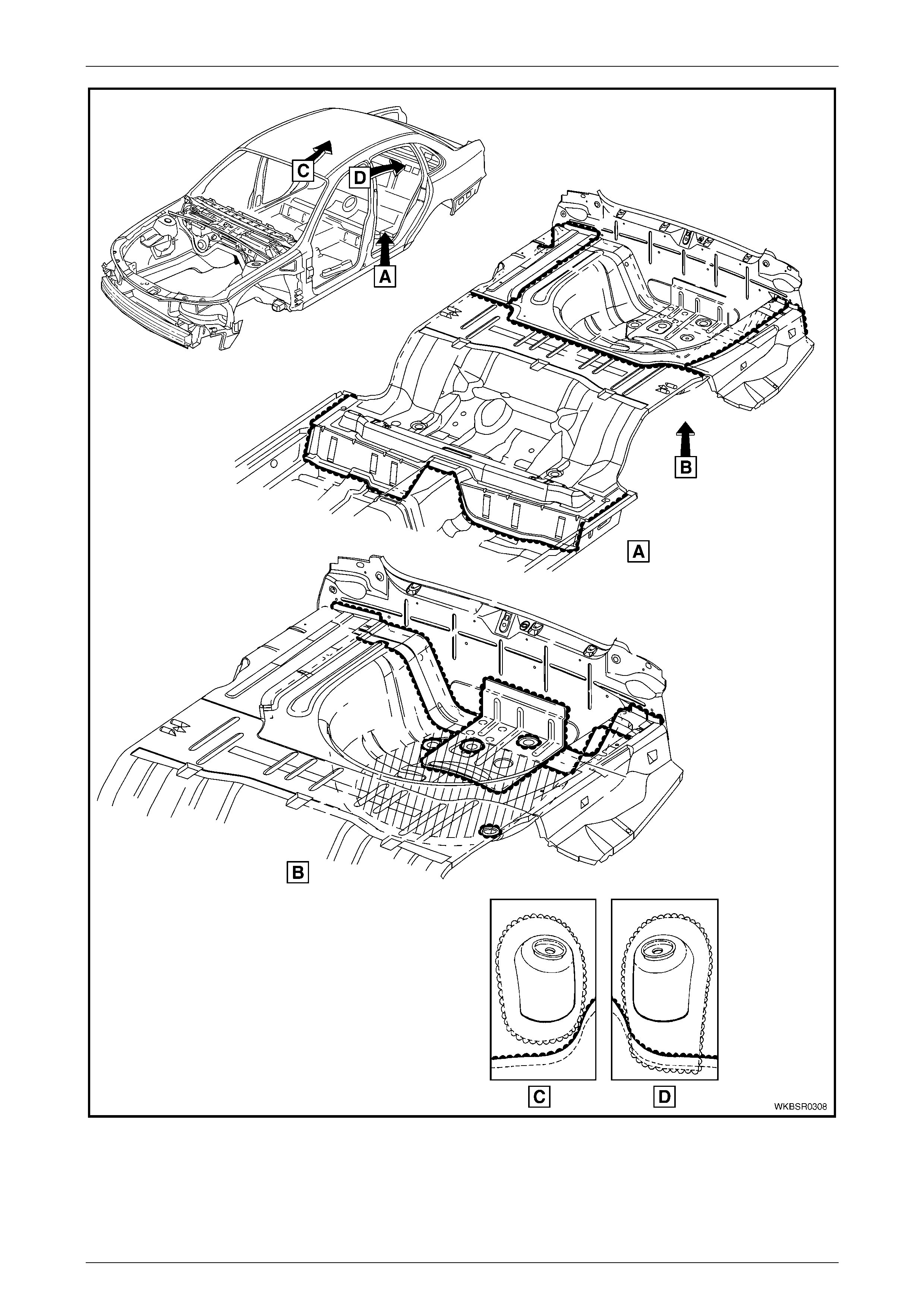
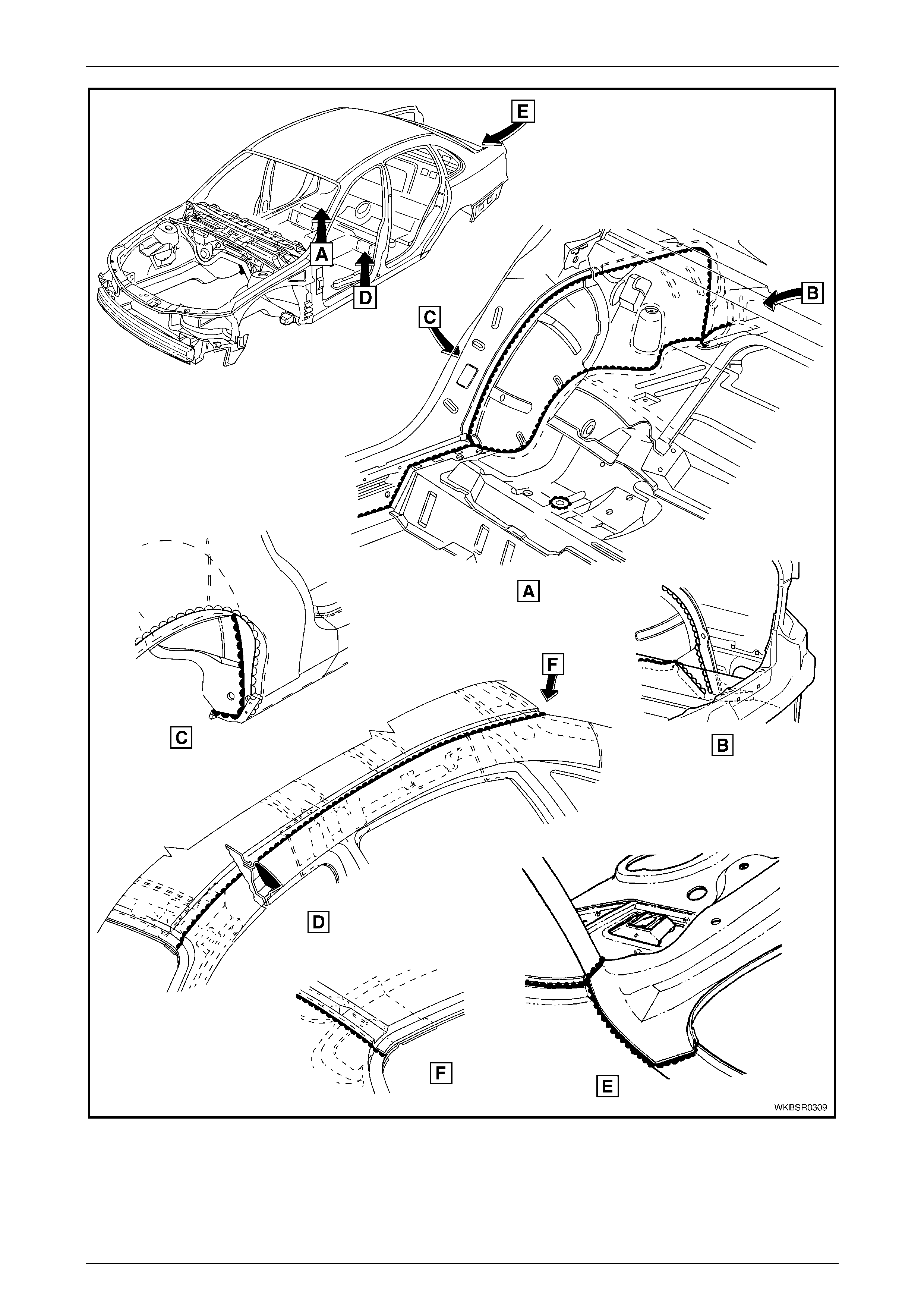
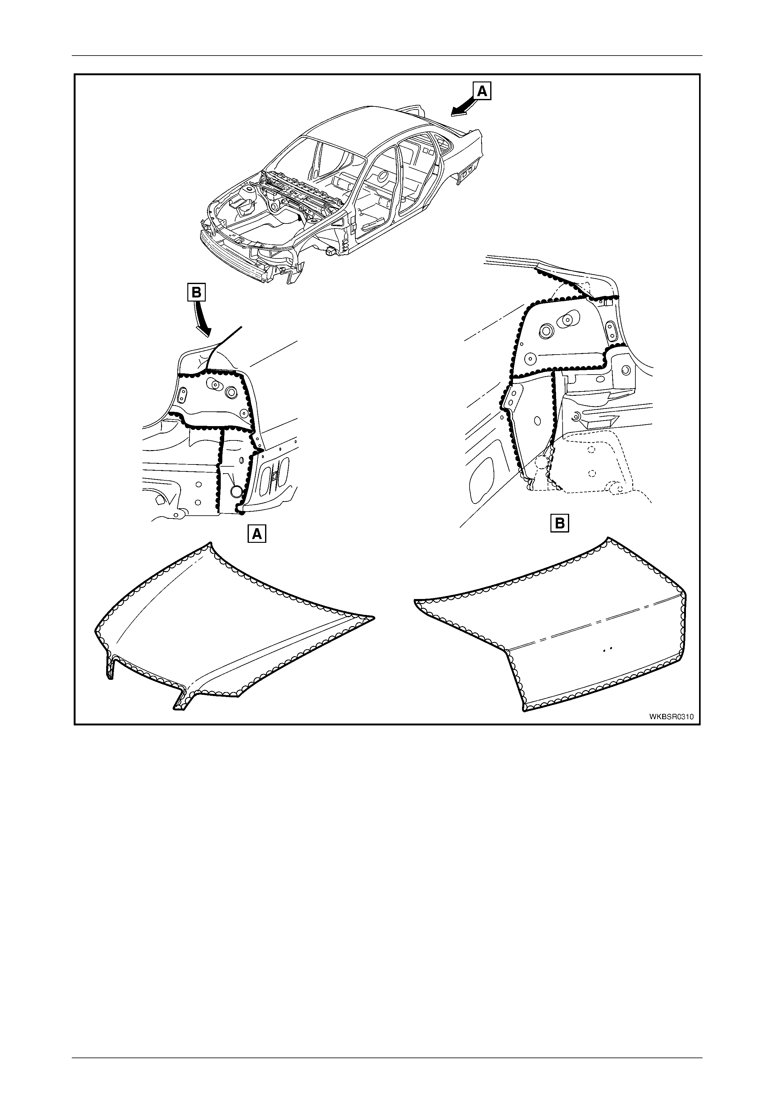
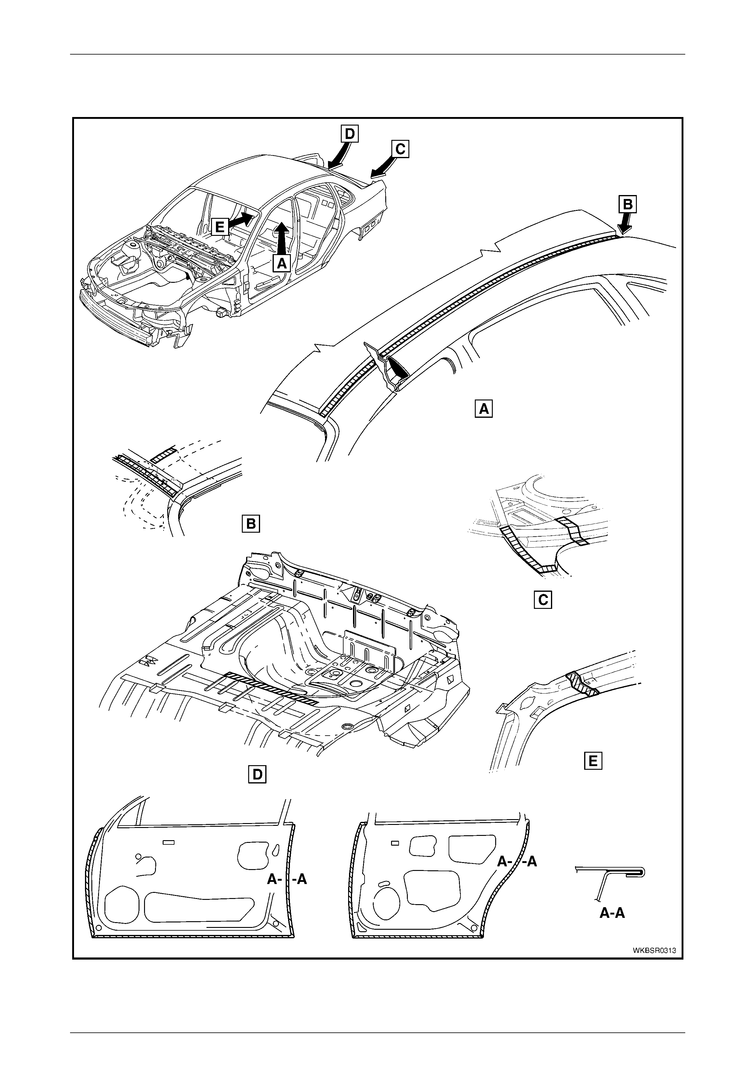
Joint Sealer (Item 3)
Primarily used for sealing joints to achieve a watertight seal. It seals notches, cut-outs and holes. Joint sealer should be
applied after priming, prior to application of the top coat. Refer to Figure 3 – 15 – Figure 3 – 20.
NOTE
Figure 3 – 16, View E illustrates the underside of
the spare wheel-well. Following priming, this area
is sprayed with sealer (rather than deadener) to a
minimum thickness of 2.5 mm and has a rough
finish. This procedure is important due to the
mounting of the fuel tank below it.
NOTE
During production a heat fusible patch is applied
along the joint of the back panel - upper, refer
Figure 3 – 18 View E. This patch is not serviced
as the heat required to fuse it is beyond the
capabilities of the repairer. Joint sealer may be
applied and finished to produce a smooth
surface.
Hand Putty (Item 4)
Hand putty, also known as caulking compound, is used in the areas marked * in Figure 3 – 20.

Body Const ruct i on Page 3–20
Page 3–20
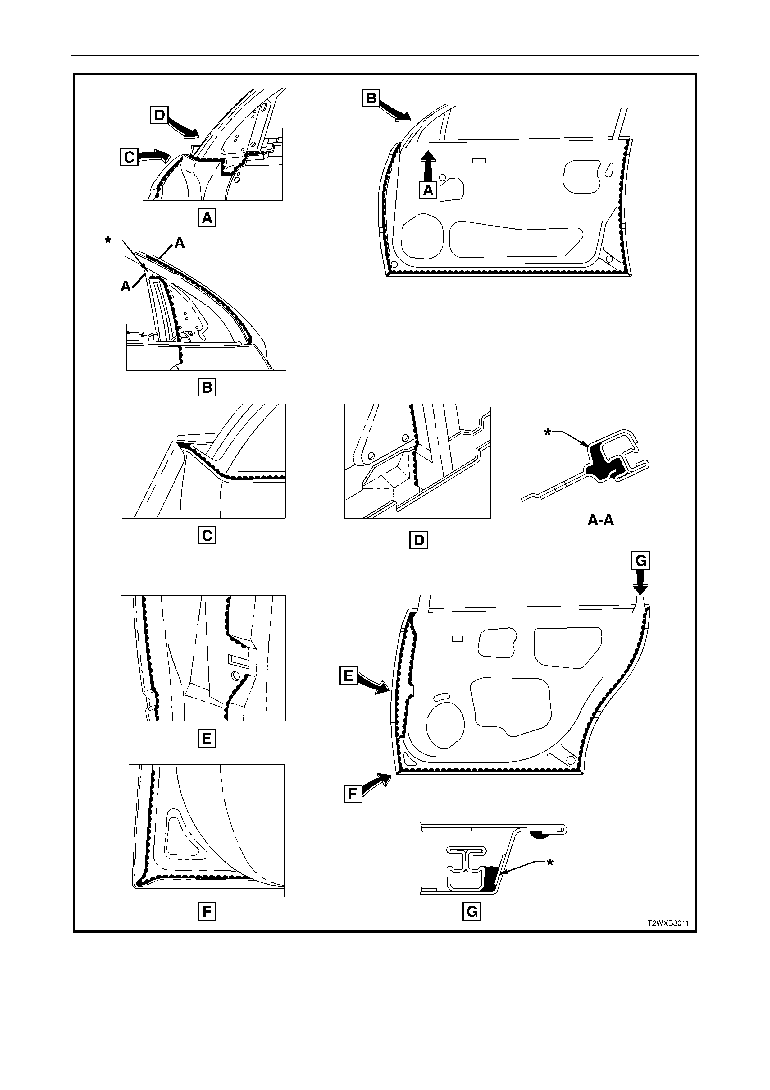
Adhesive - Anti-Flutter (Item 5)
While used as a filler between an inner and outer panel to reduce panel flex, Anti-Flutter adhesive also aids rigidity and
assists in dispersing loads over a larger area. Refer to Figure 3 – 21 and Figure 3 – 22 for locations.
Adhesive - Structural (Item 6)
Critical to the strength and rigidity of the vehicle, the correct adhesive must be used for service repairs. Using an
adhesive that is too weak will reduce the performance of the joint. Using an adhesive that is too strong can also effect the
performance of the joint, compromising the vehicle’s crash performance and safety system’s operation. This adhesive is
a 2-part system. Refer to Figure 3 – 23 for locations.
Spray-on Deadener (Item 7)
This deadener is sprayed onto the body shell after painting. It is used in the wheel-wells and on the under side of the
floor pan. A minimum thickness of 1.5 mm is required in these applications. Refer to Figure 3 – 24 for locations.
Deadener Panels
Deadener panels are sold pre-cut as Service Parts. They are installed with the coloured side up and diamond embossed
side down. The panels are installed prior to painting and some are heat fused to the body shell. Refer to Figure 3 – 25 –
Figure 3 – 28 for locations.
Sealer / Adhesive / Deadener Commercially Available Equivalents
Item No. Item Name Manufacturer Product Name
1 Weld Through Primer Refer to supplier
2 Acrylic Spot Weld Sealer Lord (Fusor)
3 Joint Sealer Sprayable: Lord (Fusor)
Extruded beads: Lord (Fusor)
3M
Visible Seams
-self leveling: Lord (Fusor)
3M
-non sag: Lord (Fusor)
3M
Fusor #802
Fusor #800 / #801
Automix 8308
Fusor #122 / #125
Automix 8307
Fusor #123 / #126
Automix 8308
4 Hand Putty Lord (Fusor)
3M
Fusor #800 / #801
Automix 8307
5 Adhesive - Anti Flutter Lord (Fusor) Fusor #124
6 Adhesive - Structural
(Two-Part) Lord (Fusor)
3M
Fusor #108 B
Automix 8115
7 Spray-on Deadener Henkel Terophon 2000-13
NOTE
Special tools may be required to apply some
materials, refer to your supplier for further
information.
Body Const ruct i on Page 3–21
Page 3–21
5.2 Acrylic Spot Weld Sealer (Item 2)
Figure 3 – 13
Legend
1 Door Opening Frame
2 Reinforcement - Hinge A-pillar
3 Shroud Side Panel
4 Closing Plate - A-pillar
5 Brace - Front Wheelhouse
Body Const ruct i on Page 3–22
Page 3–22
Figure 3 – 14
Body Const ruct i on Page 3–23
Page 3–23
5.3 Joint Sealer (Item 3)
Figure 3 – 15
Body Const ruct i on Page 3–24
Page 3–24
Figure 3 – 16
Body Const ruct i on Page 3–25
Page 3–25
Figure 3 – 17
Body Const ruct i on Page 3–26
Page 3–26
Figure 3 – 18
Body Const ruct i on Page 3–27
Page 3–27
Figure 3 – 19
Body Const ruct i on Page 3–28
Page 3–28
Figure 3 – 20
Body Const ruct i on Page 3–29
Page 3–29
5.4 Adhesive – Anti-Flutter (Item 5)
Figure 3 – 21
Body Const ruct i on Page 3–30
Page 3–30
Figure 3 – 22
Body Const ruct i on Page 3–31
Page 3–31
5.5 Adhesi ve – Structural (Item 6)
Figure 3 – 23
Body Const ruct i on Page 3–32
Page 3–32
5.6 Spray-on Deadener
Figure 3 – 24

Body Const ruct i on Page 3–33
Page 3–33
5.7 Deadener Panels & Insulators
The deadener panels shown are heat fusible type. They are to be installed with the diamond embossed side down. Use a
heat gun, heat lamps or such to cure each deadener sheet.
Figure 3 – 25
Legend
1 Deadener - Front Floor, RH
2 Deadener - Front Floor, LH
3 Deadener - Front Floor, Centre
4 Deadener - Rear Floor, RH
5 Deadener - Floor Rear, LH
6 Deadener - Rear Floor, Centre
7 Deadener - Rear Seat Floor, RH
8 Deadener - Rear Seat Floor, LH
9 Deadener - Rear Compartment , RH
10 Deadener - Rear Compartment, LH
11 Deadener - Spare Wheel Well
Body Const ruct i on Page 3–34
Page 3–34
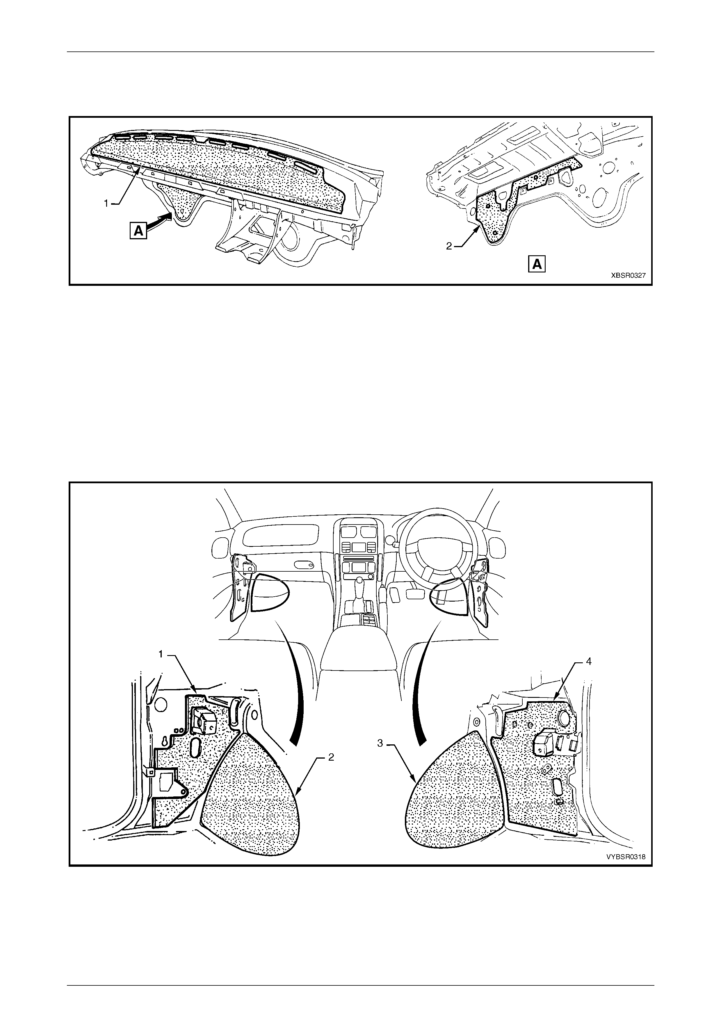
The insulator (1) is self adhesive, refer to Figure 3 - 26. To install, remove the backing paper and attach the insulator
ensuring any cut-outs align with brackets etc. Smooth the insulator firmly into position. The deadener (2) is a heat cure
type and is attached as previously described.
Figure 3 – 26
Legend
1 Insulator - Das h Panel Upper 2 Deadener - Cockpit Module
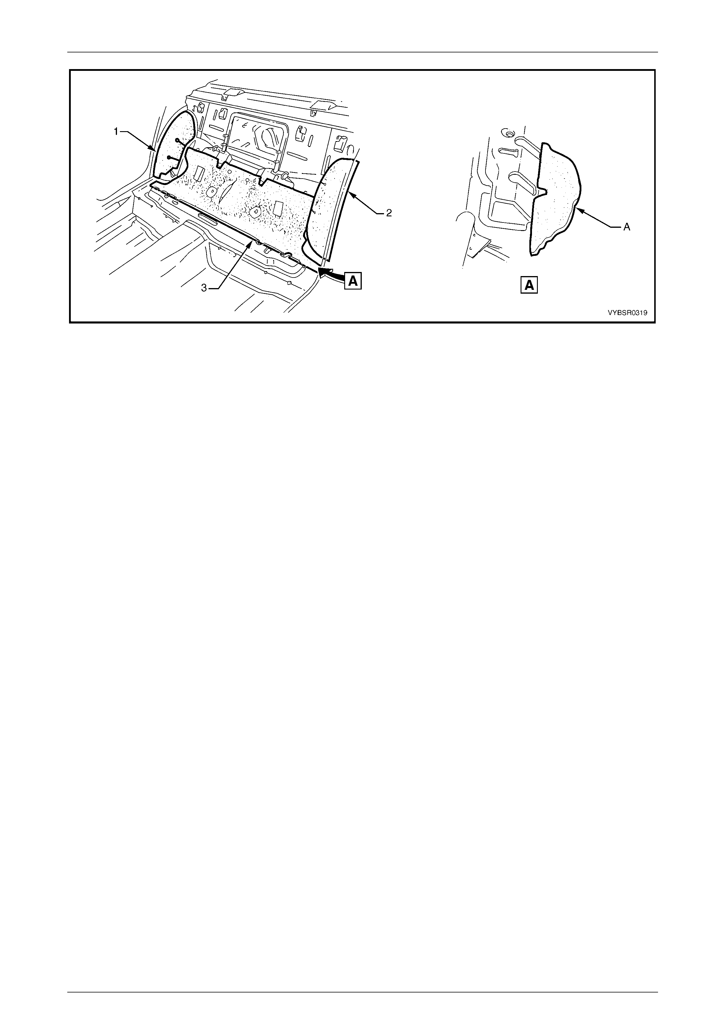
The deadeners and insulators in Figure 3 – 27 & Figure 3 – 28 are self adhesive. Remove the backing paper and attach
the insulator ensuring any cut-outs align with brackets etc. Smooth the insulator firmly into position.
NOTE
Ensure the notch in the rear seat insulators (3) in
Figure 3 – 28 is aligned with the slot in the rear
seat ramp as shown A.
Figure 3 – 27
Legend
1 Insulator - Cowl Side, LH
2 Deadener - Front Floor Extension, LH 3 Deadener - Front Floor Extension, RH
4 Insulator - Cowl Side, RH
Body Const ruct i on Page 3–35
Page 3–35
Figure 3 – 28
Legend
1 Insulator - Rear Seat Wheel house, RH
2 Insulator - Rear Seat Wheel house, LH 3 Insulator - Rear Seat
Body Const ruct i on Page 3–36
Page 3–36
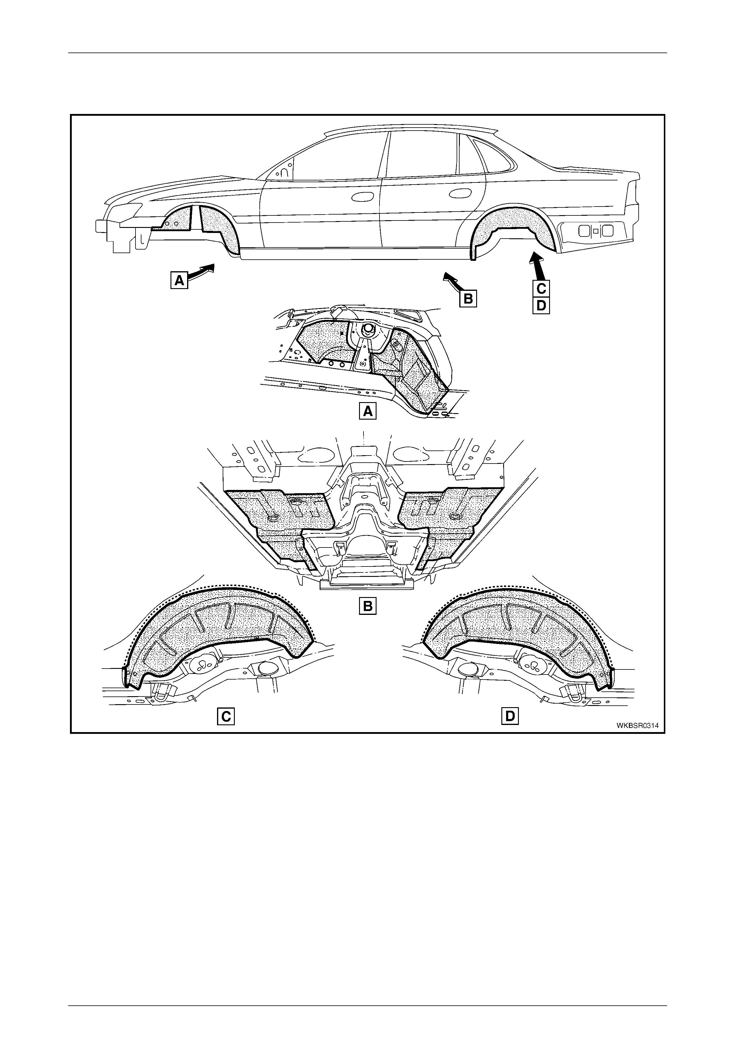
6 Cavity Wax
MY 2004 WK Series body and structural panels are constructed from high quality corrosion resistant materials. During
manufacture, cavity wax is applied to the areas shown to further increase the vehicle’s anti-corrosive properties.
Following repairs, to maintain the anti-corrosive properties of the vehicle, once the paint is thoroughly dry apply cavity
wax to the areas shown below, and within any repaired box sections or areas inaccessible to paint. Refer to the table for
equivalent products to those used in manufacture.
Cavity Wax Equivalents
Item No. Equivalent Manufacturer Equivalent Product Name
8 Henkel Terotex HV 8377/65
Nox Rust Hi-Wax 100B
Terasol 800113 (Aerosol pack)
Figure 3 – 29

Body Const ruct i on Page 3–37
Page 3–37
Figure 3 – 30
Body Const ruct i on Page 3–38
Page 3–38
Figure 3 – 31