Body Rear Page 10–1
99–AAA–2002 Page 10–1
Section 10
Body Rear
ATTENTION
Before performing any Service Operation or other procedure described in this Section, refer to Section 00
Warnings, Cautions And Notes for correct workshop practices with regard to safety and/or property damage.
The Structure of the MY 2004 WK Series
vehicle body shell has been developed using
complex design and development techniques.
In addition to meeting all required standards,
the vehicle body is also a critical part of the
overall safety systems. It is therefore
imperative the repair procedures described
here are adhered to during all vehicle body
repairs.
1 General Information............................................................................................................................... 2
1.1 Body Rear Components.........................................................................................................................................2
2 Service Operations................................................................................................................................4
2.1 Rear Compartment Floor Panel Outer Extension – Replace ..............................................................................4
Remove ...................................................................................................................................................................4
Replace ...................................................................................................................................................................5
2.2 Rear Compartment Floor Panel Assembly – Replace.........................................................................................7
Remove ...................................................................................................................................................................7
Replace ...................................................................................................................................................................8
2.3 Rear Side Rail Assembly – Replace....................................................................................................................10
Remove .................................................................................................................................................................10
Replace .................................................................................................................................................................12
Body Rear Page 10–2
99–AAA–2002 Page 10–2
1 General Information
With the following exceptions, MY 2004 WK Series body rear information carries over from MY 2003 VY Series vehicles.
For information not contained within this Section, refer to Section 10, Body Rear in the MY 2003 VY & V2 Series Service
Information Supplement, Body Structure Repair.
• Body rear components
• Rear compartment floor panel outer extension
• Rear compartment floor panel assembly
• Rear side rail assembly
This Section describes replacement procedures for the rear section components of the MY 2004 WK Series body
structure. Removal of bolt-on and mechanical components is not covered. Reference must be made to the appropriate
Sections in the MY 2004 WK Series Service Information.
When repairing the rear of the vehicle, care must be taken to ensure the structure is returned to its original production
configuration.
NOTE
It is imperative that the correct body adhesives,
sealers, deadeners and cavity waxes are
used when repairing the body structure of
MY 2004 WK Series vehicles. Refer to
Section 3, 5 Body Sealing, Adhesives &
Deadeners and 6 Cavity Wax for details of the
correct materials and their commercially available
equivalents.
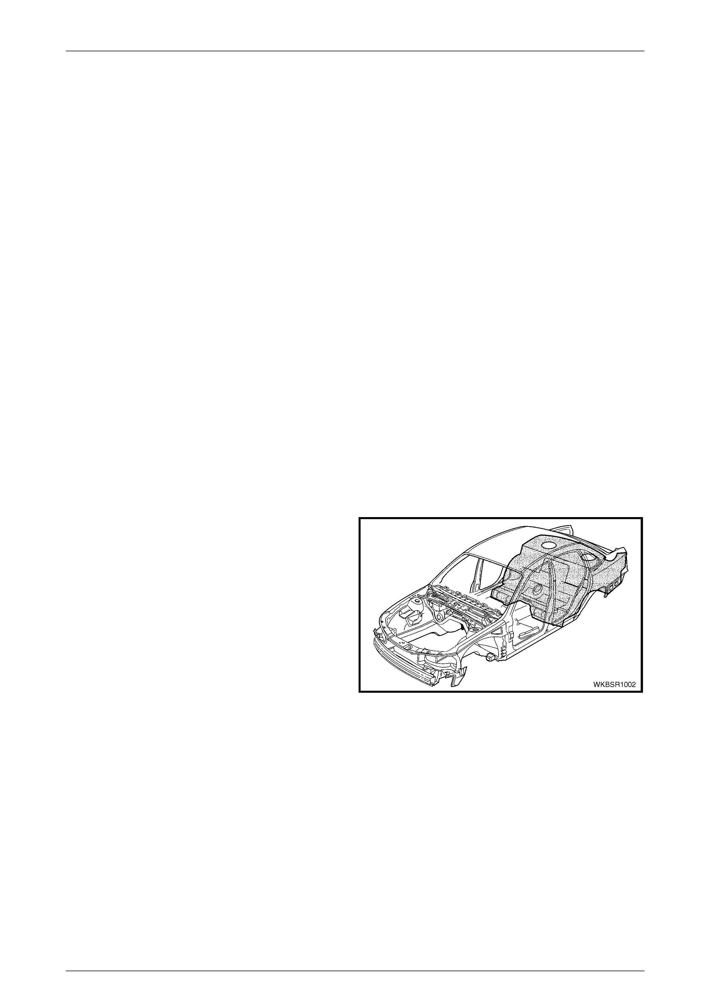
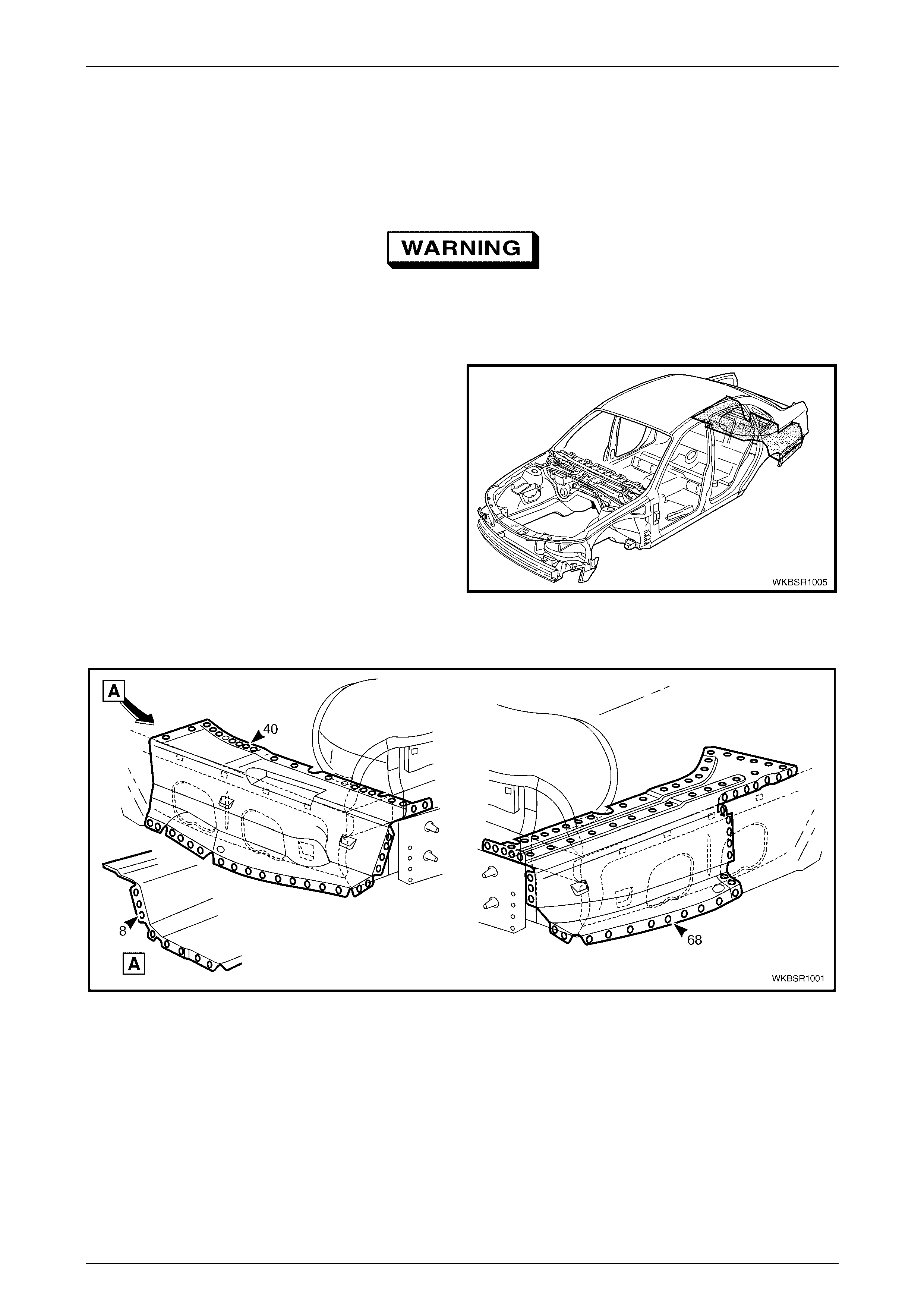
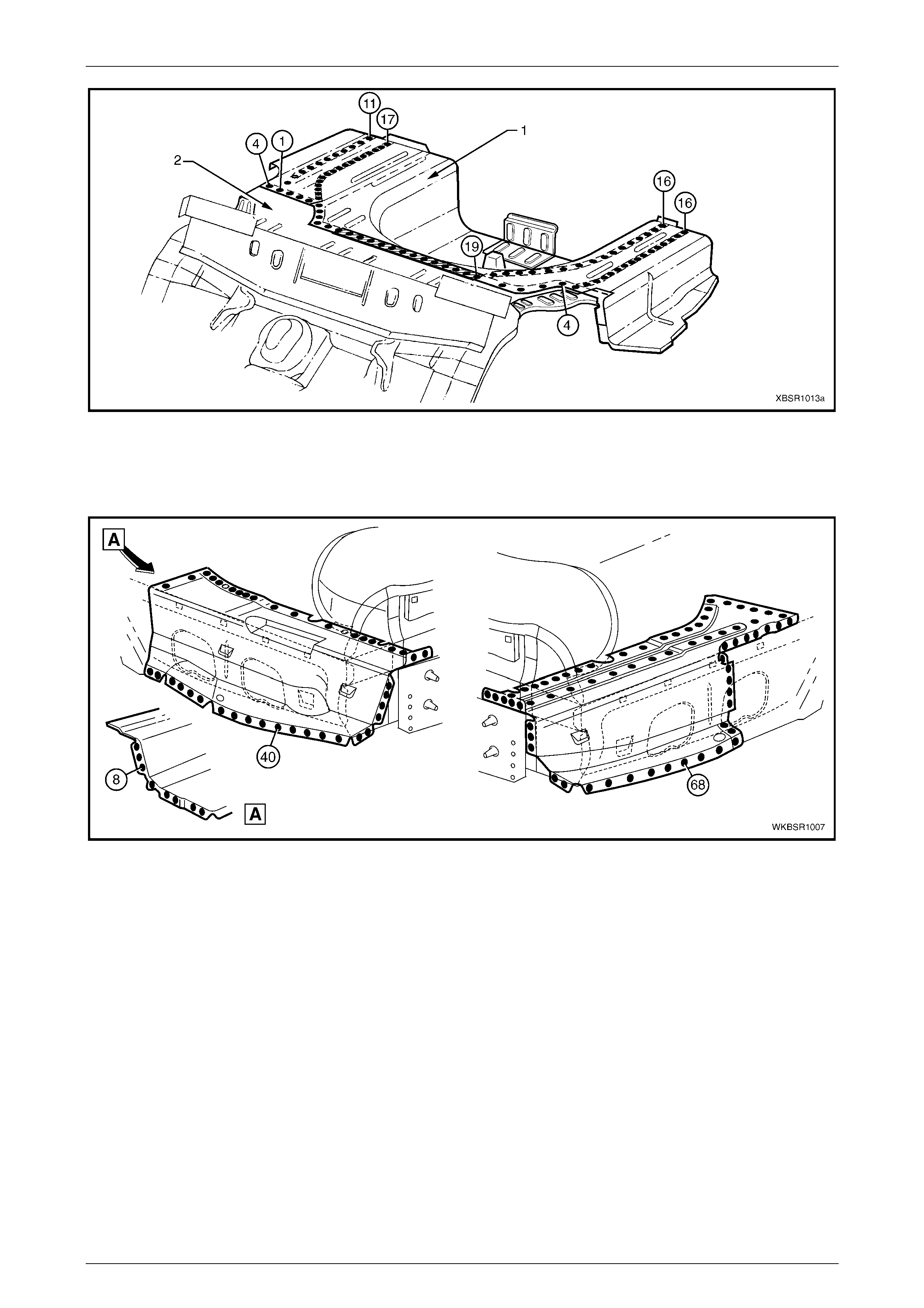
1.1 Body Rear Components
The shaded components shown are those dealt with in this
Section.
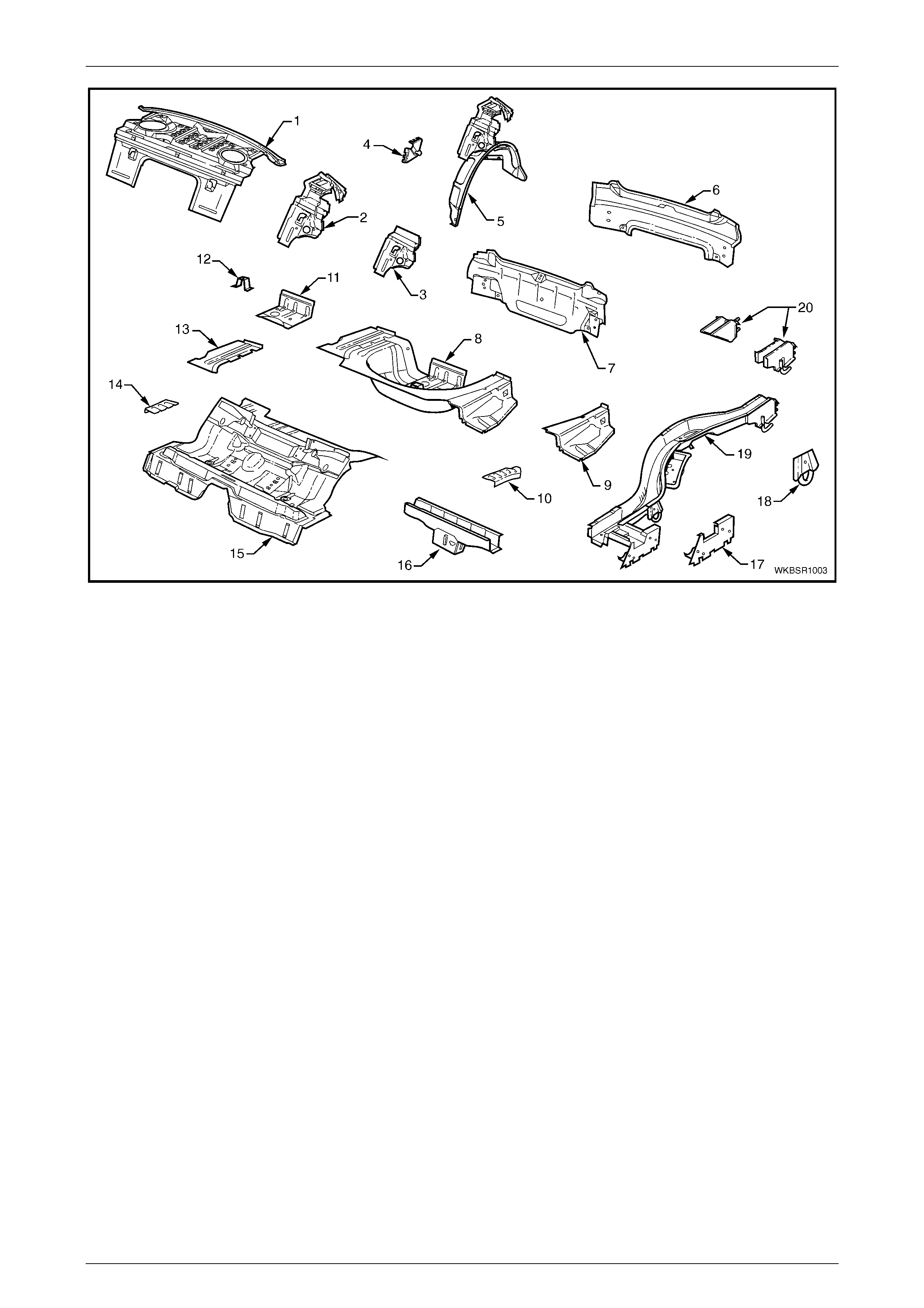
The components and assemblies shown, refer to Figure 10
– 2, are the parts serviced for MY 2004 WK Series vehicles
which form the basis of the repair procedures in this
Section. For a detailed view of the body components, refer
to Section 3, Body Construction.
NOTE
Always refer to your Authorised Retailer for
spare parts availability configurations.
Figure 10 – 1
Body Rear Page 10–3
99–AAA–2002 Page 10–3
Figure 10 – 2
Legend
1 Rear Window Panel Assembly
2 Rear Seat Back Panel Extension Assemb l y
3 Rear Seat Back Panel Extension
4 Rear Compartment Lid Strut Bracket Assem bl y
5 Rear Wheelhouse Panel Assembly
6 Rear End Lower Panel
7 Rear End Panel Assembly
8 Rear Compartment Floor Panel Assembly
9 Rear Compartment Floor Panel Outer Extension, Left-Hand
10 Rear Floor Panel Reinforcement , Left-Hand
11 Fuel Tank Support Reinforcement Assembly
12 Spare Wheel Anchor Plate Assembly
13 Rear Compartment Floor Panel Outer Extensi on,
Right-Hand
14 Rear Floor Panel Reinforc ement, Right-Hand
15 Rear Floor Panel Assembly
16 Crossm ember Assem bly No. 2
17 Rear Floor Panel Outer Extension
18 Rear Tie Down Assembly
19 Rear Side Rail Assembly
20 Rear Bumper Impact Bar Brace Assembly
• Rear wheelhouse panel assembly includes part 2, which includes parts 3 & 4.
• Rear compartment floor panel assembly includes parts No. 10, 12, 13 & 14.
• Rear side rail assembly includes parts No. 18, 19 & 21.
Body Rear Page 10–4
99–AAA–2002 Page 10–4
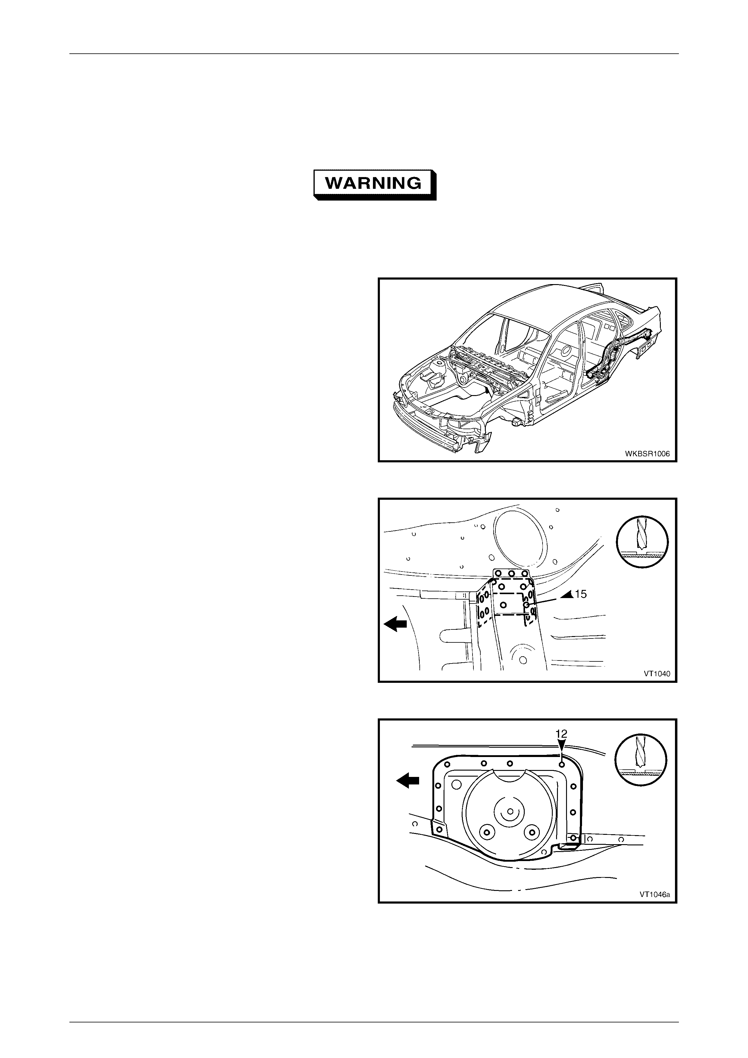
2 Service Operations
2.1 Rear Compartment Floor Panel Outer
Extension – Replace
Remove
To avoid the possibility of fire, take particular
care when cutting or welding at the rear of the
vehicle. Remove the fuel tank and plug all fuel
lines.
1 Remove the adjacent bolt-on panels and components
as described in the appropriate Section of the
MY 2004 W K Series Service Information.
2 Remove the joint sealer from around the rear
compartment flo or panel outer extension join s as
required.
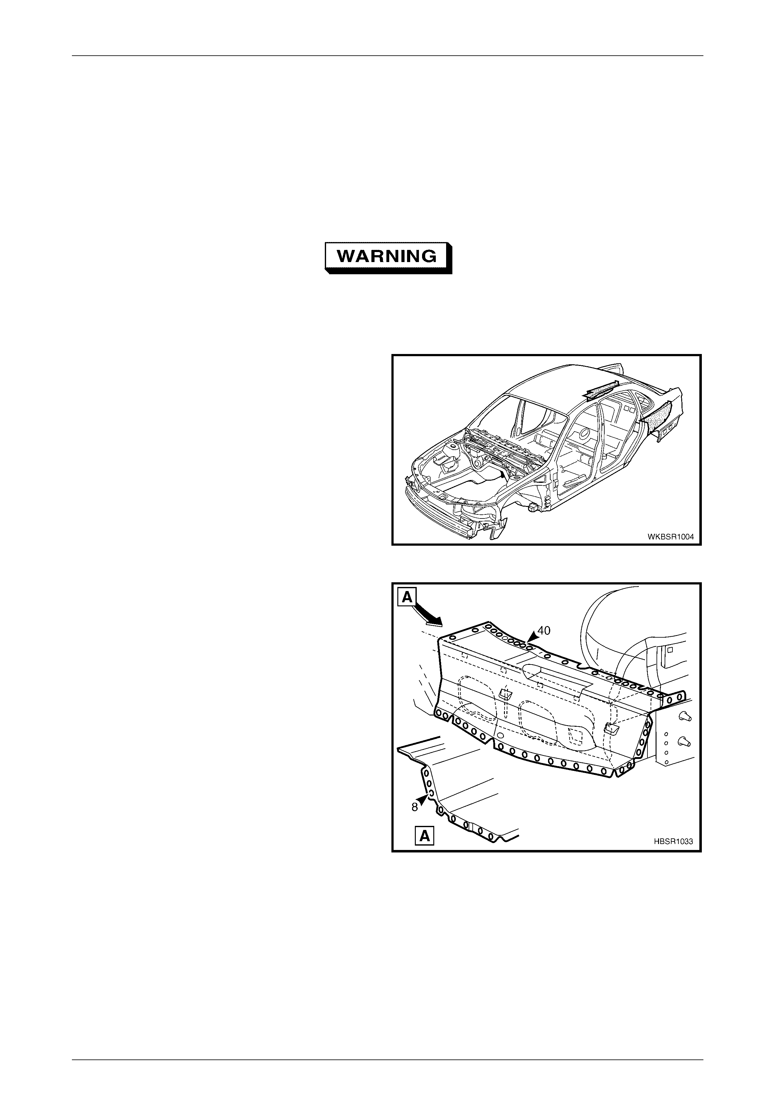
Figure 10 – 3
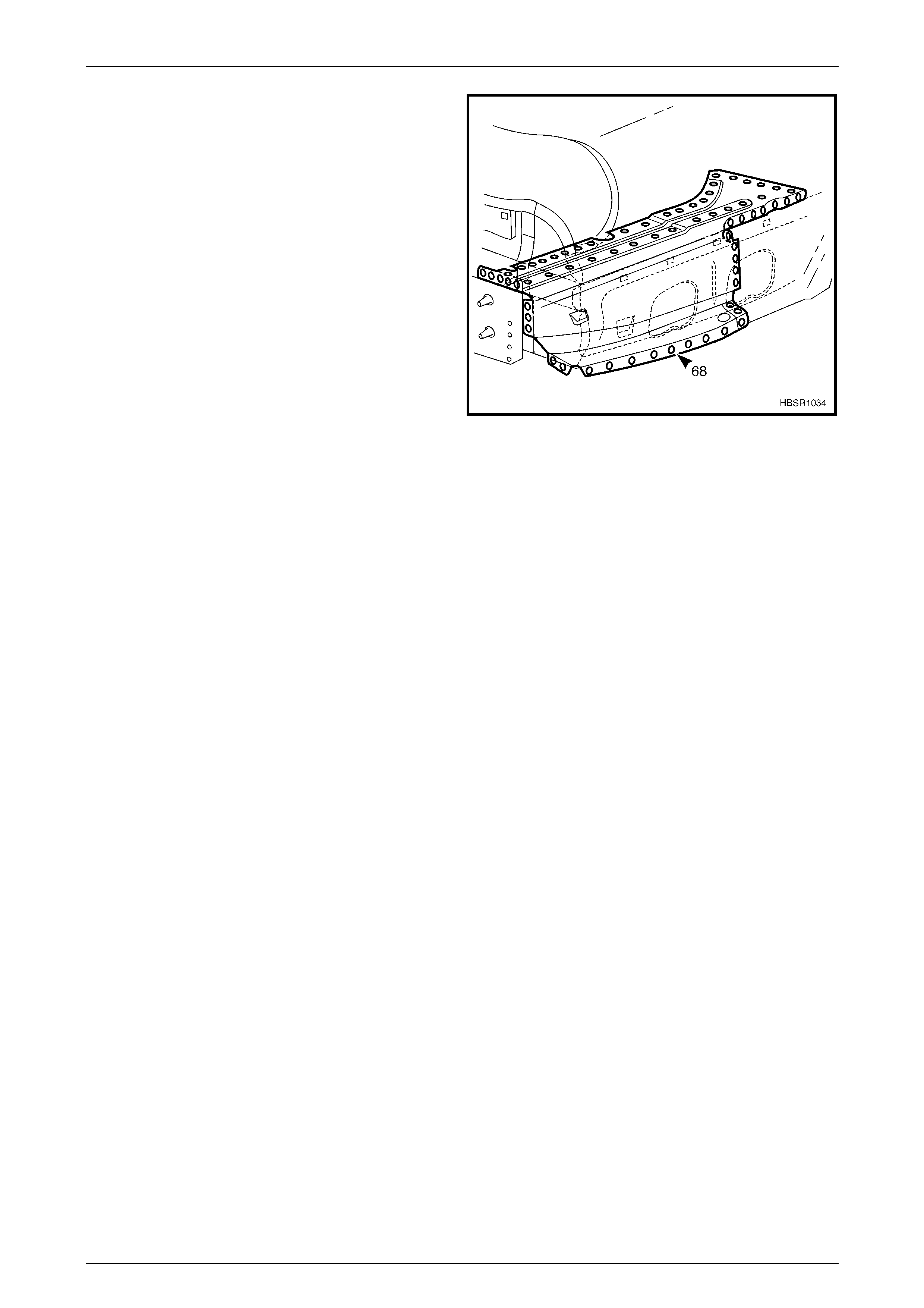
3 Spot cut the welds attaching the rear compartment
floor panel outer extension to the rear compartment
floor panel, rear side rail assembly, rear quarter panel
and rear wheelhouse panel as required. Refer to
Figure 10 – 4 for left-hand or Figure 10 – 5 for right-
hand.
NOTE
Also remove several welds from the left-hand
rear floor panel reinforcement as shown.
4 Remove the extension from the vehicle and then
repair any damage to adjacent parts as required.
5 Check and rectify the alignment of the body as
required, refer to Section 3, 3 Body Dimensions .
Figure 10 – 4
Body Rear Page 10–5
99–AAA–2002 Page 10–5
Figure 10 – 5
Replace
NOTE
Spot welding is the preferred method for
attaching of panels and should be used whenever
possible. Where the spot welding equipment will
not access the required weld position, a plug
weld should be performed.
NOTE
The same number and position of spot welds (or
plug welds) should be used when replacing the
panel, as was used during manufacture, in order
to maintain the original structural strength of the
vehicle.
1 As required, mark the new panel with drilling locations in preparation for plug welding. Drill holes as required.
2 Prepare all mating surfaces and treat with Weld Through Primer (Item 1) as required, refer to Se ction 3, 5 Body
Sealing, Adhesives & Deadeners.
3 Apply Acrylic Spot Weld Sealer (Item 2), refer to Section 3, 5 Body Sealing, Adhesives & Deadeners.
Body Rear Page 10–6
99–AAA–2002 Page 10–6
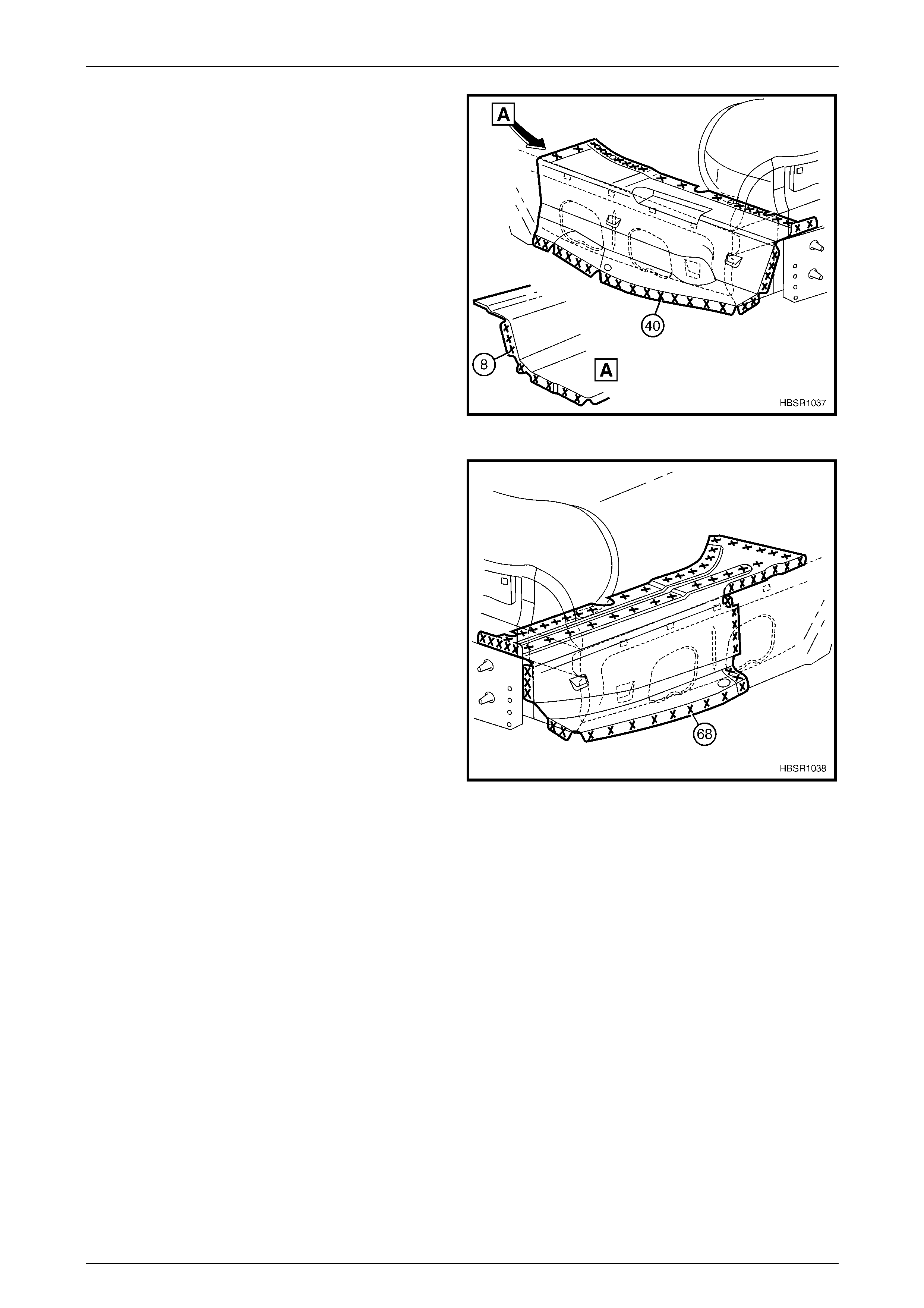
4 Fit the left-hand rear compartment floor panel outer
extension in position, ensuring the front edge is seated
under the rear floor panel reinforcement.
5 Spot or plug weld the extension to the rear
compartment flo or panel, rear floor panel
reinforcement, rear side rail assembly, rear quarter
panel and the rear wheelhouse panel as required.
Figure 10 – 6
6 Fit the right-hand rear compartment floor panel outer
extension and spot or plug weld it to the rear
compartment floor panel, rear side rail assembly, rear
quarter panel and the rear wheelhouse panel as
required.
7 Replace the removed adjacent bolt-on panels and
components as described in the appropriate Section of
the MY 2004 WK Series Service Information.
8 Refinish and paint panels and other components as
required. Refer to Section 3, 1.3 Paint Refinishing in
the MY 2003 VY & V2 Series II Service Information.
9 Apply Joint Sealer (Item 3) as required. Refer to
Section 3, 5 Body Sealing, Adhesives & Deadeners.
10 Apply Cavity Wax (Item 8) as required to the inside of
any box sections or areas inaccessible to paint, refer
to Sect ion 3, 6 Cavit y Wax.
11 Apply Spray-on Deadener (Item 7) where applicable,
refer to Section 3, 5 Body Sealing, Adhesives &
Deadeners.
12 Install the remaining components as described in the
appropriate Section of the MY 2004 WK Series
Service Information.
Figure 10 – 7
Body Rear Page 10–7
99–AAA–2002 Page 10–7
2.2 Rear Compartment Floor Panel
Assembly – Replace
Remove
To avoid the possibility of fire, take particular
care when cutting or welding at the rear of the
vehicle. Remove the fuel tank and plug all fuel
lines.
1 Remove the adjacent bolt-on panels and components
as described in the appropriate Section of the
MY 2004 W K Series Service Information.
2 Secure the vehicle on a suitable fixture and use a
suitable brace to maintain the alignment of the rear
side rail assemblies prior to removal of the rear end
panel assembly.
3 Remove the rear end panel assembly, refer to
Section 10, 2.2 Rear End Panel Assembly – Replace
in the MY 2003 VY & V2 Series II Service Information.
4 Remove the joint sealer from the surrounding area
using a scraper and heat gun.
5 As required, spot cut each rear compartment floor
panel outer extension from the rear wheelhouse panel
and rear quarter panel, refer to Figure 10 – 9.
Figure 10 – 8
Figure 10 – 9
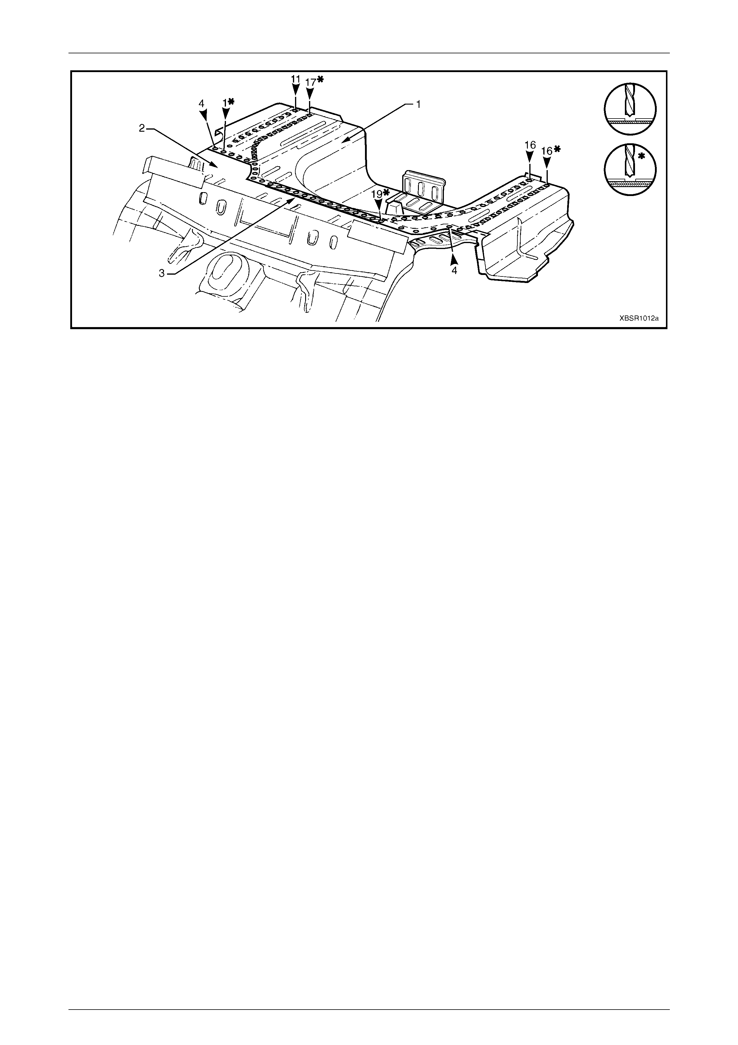
6 Spot cut the welds attaching the rear compartment floor panel assembly (1) to the rear floor panel assembly (2) and
to the rear side rail assemblies, refer to Figure 10 – 10.
NOTE
Structural adhesive is applied in the area shown
(3), refer to Section 3, 5 Body Sealing, Adhesives
& Deadeners.
Body Rear Page 10–8
99–AAA–2002 Page 10–8
Figure 10 – 10
7 Remove the rear compartment floor panel assembly from the vehicle and repair any damage to adjacent parts as
required.
8 Check and rectify the alignment of the body as required, refer to Section 3, 3 Body Dimensions.
Replace
NOTE
Spot welding is the preferred method for
attaching of panels and should be used whenever
possible. Where the spot welding equipment will
not access the required weld position, a plug
weld should be performed.
NOTE
The same number and position of spot welds (or
plug welds) should be used when replacing the
panel, as was used during manufacture, in order
to maintain the original structural strength of the
vehicle.
1 As required, mark the new panel with drilling locations in preparation for plug welding. Drill holes as required.
2 Prepare all mating surfaces and treat with Weld Through Primer (Item 1) as required, refer to Se ction 3, 5 Body
Sealing, Adhesives & Deadeners.
3 Apply Acrylic Spot Weld Sealer (Item 2), refer to Section 3, 5 Body Sealing, Adhesives & Deadeners.
4 Apply Structural Adhesive (Item 6), refer to Section 3, 5 Body Sealing, Adhesives & Deadeners.
5 Install the rear compartment floor panel assembly (1) ensuring it is seated under the left-hand rear floor panel
reinforcement.
6 Plug weld along the join of the rear floor panel assembly (2) and to the rear side rail assemblies, refer to Figure 10
– 11.
Body Rear Page 10–9
99–AAA–2002 Page 10–9
Figure 10 – 11
7 As required, spot or plug weld each rear compartment floor panel outer extension to the rear wheelhouse panel,
rear quarter panel, rear end panel assembly and for the left-hand side, the rear floor panel reinforcement, refer to
Figure 10 – 12.
Figure 10 – 12
8 Install the rear end panel and other panels as required, refer to the appropriate Section of the MY 2004 WK Series
Service Information.
9 Refinish and paint panels and other components as required. Refer to Section 3, 1.3 Paint Refinishing in the
MY 2003 VY & V2 Series II Service Information.
10 Apply Joint Sealer (Item 3) as required. Refer to Section 3, 5 Body Sealing, Adhesives & Deadeners.
11 Apply deadener panels to the rear compartment floor panel, refer to Section 3, 5. 6 Deadener Panels & Insul ators .
12 Apply Cavity Wax (Item 8) as required to the inside of any box sections or areas inaccessible to paint, refer to
Section 3, 6 Cavity Wax.
13 Apply Spray-on Deadener (Item 7) where applicable, refer to Section 3, 5 Body Sealing, Adhesives & Deadeners.
14 Install the remaining components as described in the appropriate Section of the MY 2004 W K Series Service
Information.
Body Rear Page 10–10
99–AAA–2002 Page 10–10
2.3 Rear Side Rail Assembly – Replace
Remove
To avoid the possibility of fire, take particular
care when cutting or welding at the rear of the
vehicle. Remove the fuel tank and plug all fuel
lines.
1 Remove the adjacent bolt-on panels and components
as described in the appropriate Section of the
MY 2004 W K Series Service Information.
2 Secure the vehicle on a suitable fixture. As a
minimum, support the appropriate structural sections
of the vehicle on safety stands. Ensure that the stands
are clear of the rear side rail assembly(s) being
removed.
Figure 10 – 13
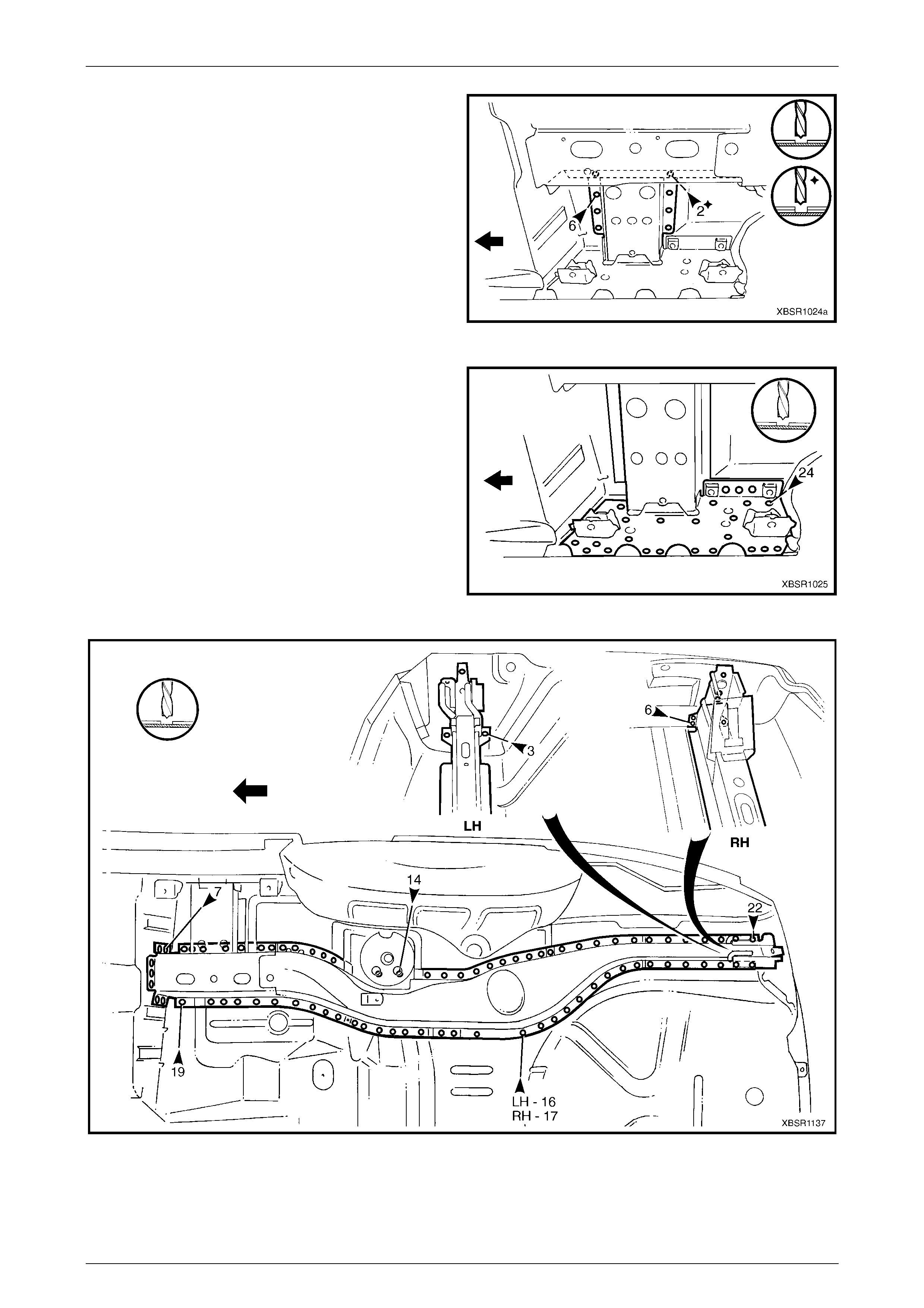
3 Spot cut the welds attaching the crossmember No.2 to
the crossmember bracket and to the rear side rail, on
each side of the vehicle.
Figure 10 – 14
4 Spot cut the welds attaching the rear side rail
assembly to the rear floor panel assembly.
Figure 10 – 15
Body Rear Page 10–11
99–AAA–2002 Page 10–11
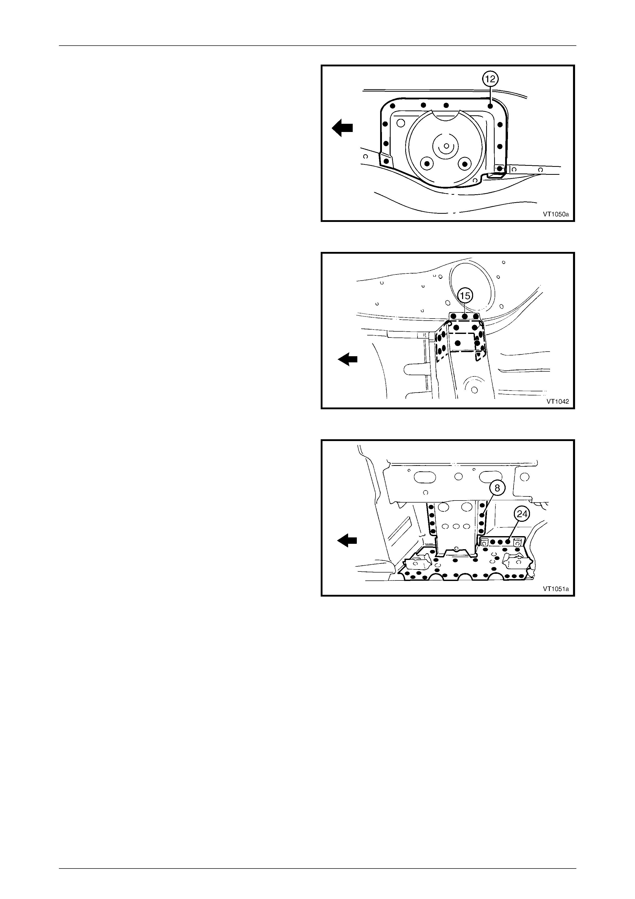
5 Spot cut the welds attaching the rear side rail
assembly to the rear floor panel assembly.
Figure 10 – 16
6 Spot cut the welds attaching the rear floor panel outer
extension to the inner rocker panel assembly.
7 Spot cut the rear side rail assembly from the rear floor
panel assembly, rear compartment floor panel
assembly and the rear end panel, refer to Figure 10 –
18.
NOTE
There are a different number of welds between
the left-hand and right-hand sides.
8 Remove the rear side rail assembly from the vehicle.
Figure 10 – 17
Figure 10 – 18
9 Repair any damage to adjacent parts as required.
10 Check and rectify the alignment of the body as required, refer to Section 3, 3 Body Dimensions.
Body Rear Page 10–12
99–AAA–2002 Page 10–12
Replace
NOTE
Spot welding is the preferred method for
attaching of panels and should be used whenever
possible. Where the spot welding equipment will
not access the required weld position, a plug
weld should be performed.
NOTE
The same number and position of spot welds (or
plug welds) should be used when replacing the
panel, as was used during manufacture, in order
to maintain the original structural strength of the
vehicle.
1 As required, mark the new panel with drilling locations in preparation for plug welding. Drill holes as required.
2 Prepare all mating surfaces and treat with Weld Through Primer (Item 1) as required, refer to Se ction 3, 5 Body
Sealing, Adhesives & Deadeners.
Prior to plug welding in this region, remove
the deadener from the inside floor to remove
the risk of fire.
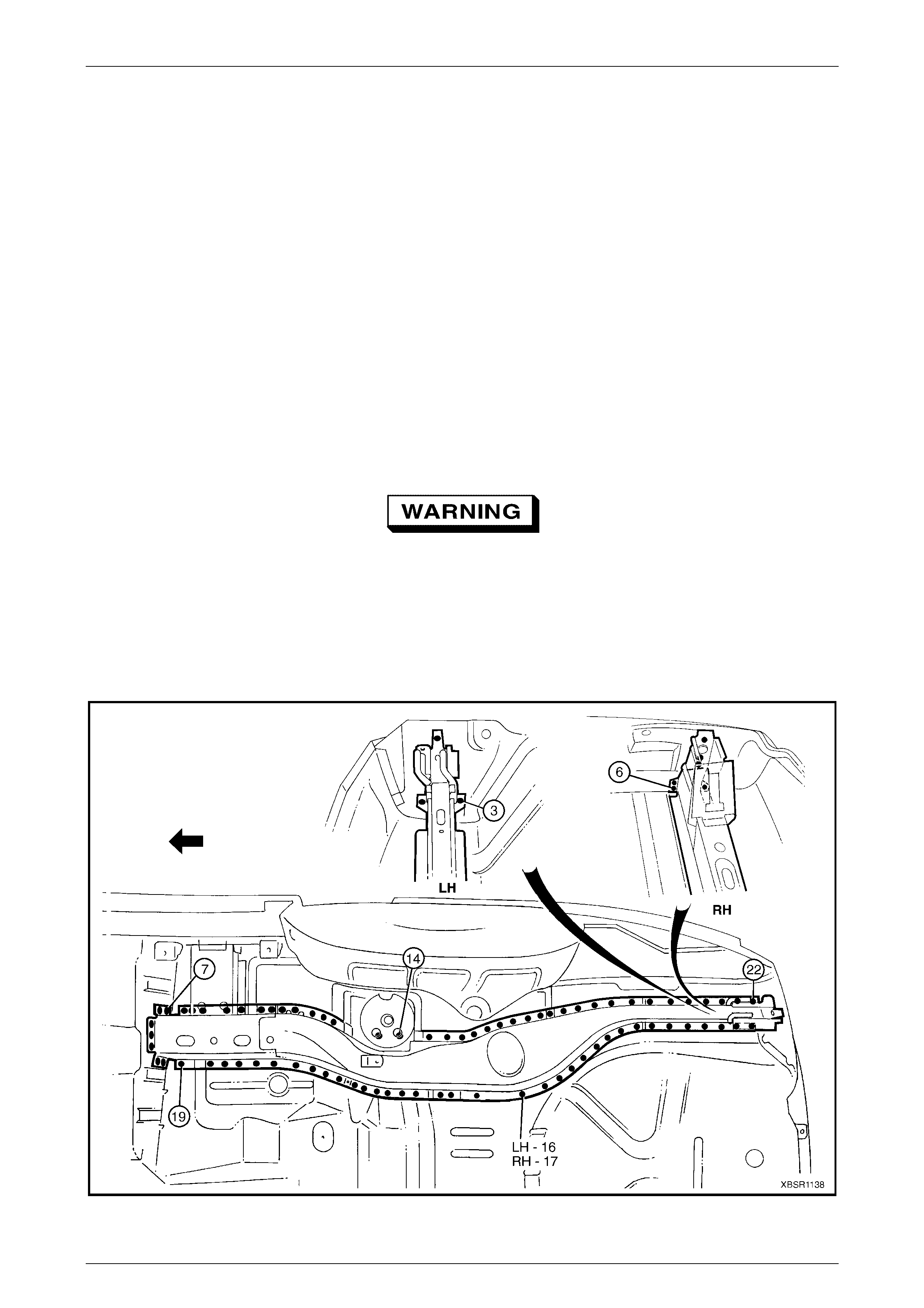
3 Locate and clamp the new rear side rail assembly in position and check and adjust its alignment, refer to
Section 3, 3 Body Dimensions.
4 Plug weld the rear side rail assembly to the rear floor panel assembly, rear compartment floor panel assembly and
the rear end panel, refer to Figure 10 – 19.
Figure 10 – 19
Body Rear Page 10–13
99–AAA–2002 Page 10–13
5 Plug weld the rear side rail assembly to the rear floor
panel assembly.
Figure 10 – 20
6 Plug weld the crossmember assembly No. 2 to the
crossmember bracket and rear side rail.
Figure 10 – 21
7 Plug weld the rear side rail assembly to the rear floor
panel assembly and the rear floor panel outer
extension to the inner rocker panel assembly.
8 Refinish and paint panels and other components as
required. Refer to Section 3, 1.3 Paint Refinishing in
the MY 2003 VY & V2 Series II Service Information.
9 Apply Joint Sealer (Item 3) as required. Refer to
Section 3, 5 Body Sealing, Adhesives & Deadeners.
10 Apply Cavity Wax (Item 8) as required to the inside of
any box sections or areas inaccessible to paint, refer
to Sect ion 3, 6 Cavit y Wax.
11 Install the remaining components as described in the
appropriate Section of the MY 2004 WK Series
Service Information.
Figure 10 – 22