
SECTION 3C - FRONT SUSPENSION (MY2002)
Service Precaution
General Description
Diagnosis
Shock Absorber
Shock Absorber and Associated Parts
Removal
Inspection and Repair
Installation
Stabilizer Bar
Stabilizer Bar and Associated Parts
Removal
Inspection and Repair
Installation
Torsion Bar
Torsion Bar and Associated Parts
Removal
Inspection and Repair
Installation
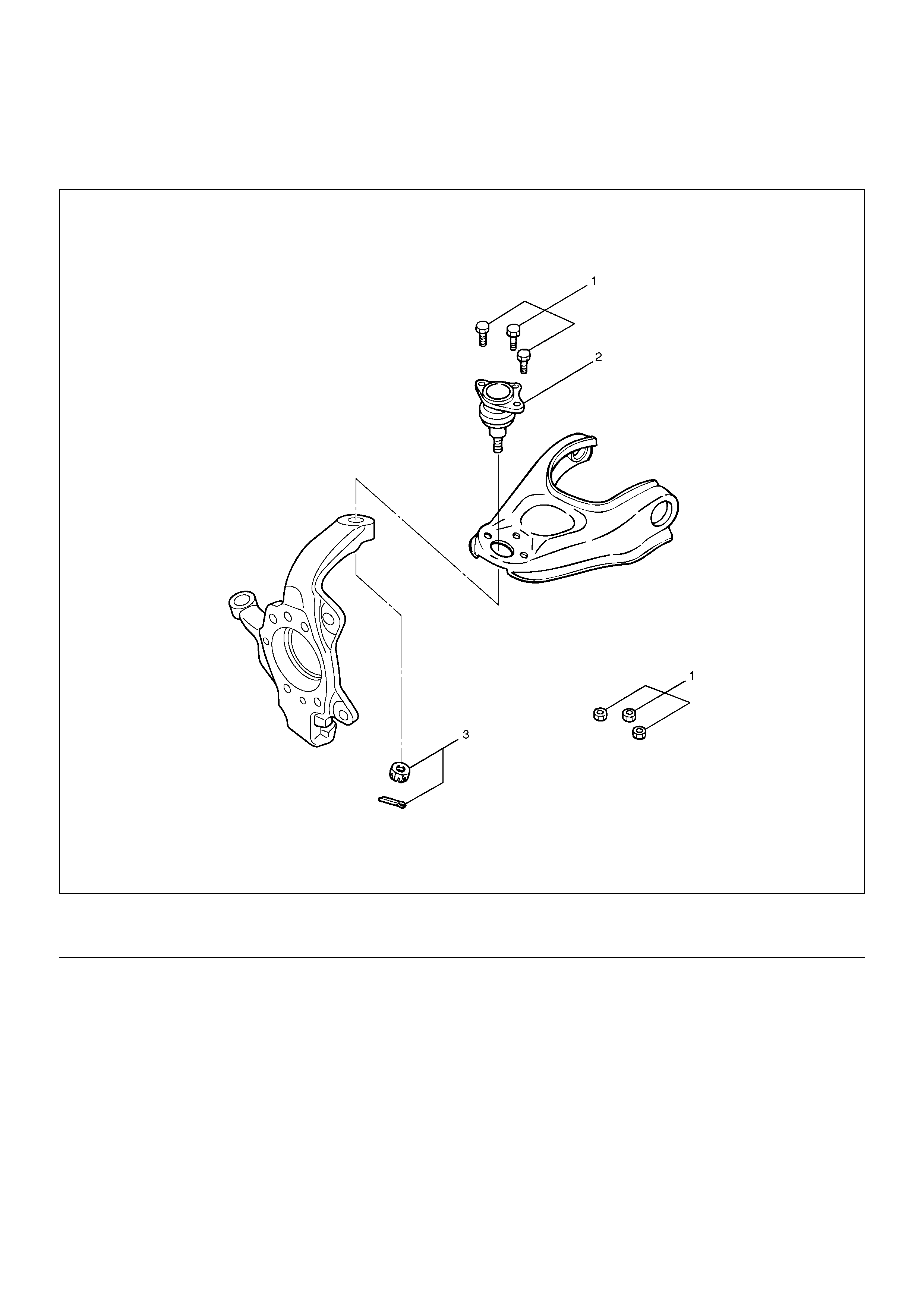
Knuckle
Knuckle and Associated Parts
Removal
Inspection and Repair
Installation
Upper Control Arm
Upper Control Arm and Associated Parts
Removal
Inspection and Repair
Installation
Lower Control Arm
Lower Control Arm and Associated Parts
Removal
Inspection and Repair
Installation
Upper Ball Joint
Upper Ball Joint and Associated Parts
Removal
Inspection and Repair
Installation
Lower Ball Joint
Lower Ball Joint and Associated Parts
Removal
Inspection and Repair
Installation
Main Data and Specifications
Special Tools
Service Precaution
WARNING: THIS VEHICLE HAS A SUPPLEMENTAL
RESTRAINT SYSTEM (SRS). REFER TO THE SRS
COMPONENT AND WIRING LOCATION VIEW IN
ORDER TO DETERMINE WHETHER YOU ARE
PERFORMING SERVICE ON OR NEAR THE SRS
COMPONENTS OR THE SRS WIRING. WHEN YOU
ARE PERFORMING SERVICE ON OR NEAR THE
SRS COMPONENTS OR THE SRS WIRING, REFER
TO THE SRS SERVICE INFORMATION. FAILURE TO
FOLLOW WARNINGS COULD RESULT IN POSSIBLE
AIR BAG DEPLOYMENT, PERSONAL INJURY, OR
OTHERWISE UNNEEDED SRS SYSTEM REPAIRS.
CAUTION: Always use the correct fastener in the
proper location. When you replace a fastener, use
ONLY the exact part number for that application.
HOLDEN will call out those fasteners that require a
replacement after removal. HOLDEN will also call
out the fasteners that require thread lockers or
thread sealant. UNLESS OTHERWISE SPECIFIED,
do not use supplemental coatings (Paints, greases,
or other corrosion inhibitors) on threaded fasteners
or fastener joint interfaces. Generally, such
coatings adversely affect the fastener torque and
the joint clamping force, and may damage the
fasteners. When you install fasteners, use the
correct tightening sequence and specifications.
Following these instructions can help you avoid
damage to parts and systems.
General Description
The front suspension is designed to allow each wheel to
compensate for changes in the road surface level
without greatly affecting the opposite wheel. Each wheel
is independently connected to the frame by a steering
knuckle, ball joint assemblies, and upper and lower
control arms. The front wheels are held in proper
relationship to each other by two tie-rods which are
connected to steering arms on the knuckles, and to a
steering unit.
All models have a front suspension system consisting of
control arms, stabilizer bar, shock absorber and a
torsion bar. The front end of the torsion bar is attached
to the lower control arm. The rear of the torsion bar is
mounted into a height control arm at the crossmember.
Vehicle trim height is controlled by adjusting this arm.
Shock absorbers are mounted between the brackets on
the frame and the lower control arms. The lower portion
of each shock absorber is attached to the lower control
arm. The upper portion of each shock absorber extends
through a frame bracket and is secured with two rubber
bushings, two retainers and a nut.
Ball joint assemblies are bolted to the outer end of the
upper and lower control arm and are attached to the
steering knuckle.
The inner ends of the upper control arm have pressed in
bushings. Bolts, passing through the bushing, attach the
control arm to the frame. The inner ends of the lower
control arm are attached to the frame by bolts passing
through the bushings.
Side roll of the front suspension is controlled by a spring
steel stabilizer bar. It is mounted in rubber bushings,
which are held to the frame by brackets. The ends of the
stabilizer bar are connected to the lower control arms by
links.
Diagnosis
Condition Possible cause Correction
Vehicle Pulls Mismatched or uneven tyres. Replace tyre.
Tyres not adequately inflated. Adjust tyre pressure.
Broken or sagging springs. Replace spring.
Radial tyre lateral force. Replace tyre.
Improper wheel alignment. Adjust wheel alignment.
Brake dragging in one wheel. Repair brake.
Loose, bent or broken front or rear
suspension parts.
Tighten or replace the appropriate
suspension part(s).
Faulty shock absorbers. Replace shock absorber.
Parts in power steering valve
defective.
Replace power steering unit.
Abnormal or Excessive Tyre Wear Sagging or broken spring. Replace spring.
Tyre out of balance. Balance or replace tyre.
Improper wheel alignment. Check front end alignment.
Faulty shock absorber. Replace shock absorber.
Hard driving. Replace tyre.
Overloaded vehicle. Replace tyre and reduce load.
Tyres not rotated periodically. Replace or rotate tyre.
Worn or hub unit bearings. Replace hub unit bearing.
Wobbly wheel or tyres. Replace wheel or tyre.
Tyres not adequately inflated. Adjust the pressure.
Wheel Hop Blister or bump on tyre. Replace tyre.
Improper shock absorber operation. Replace shock absorber.
Shimmy, Shake or Vibration Tyre or wheel out of balance. Balance wheels or replace tyre/or
wheel.
Loose hub unit bearings. Replace hub unit bearing.
Worn steering linkage ball joints. Replace ball joints.
Worn upper or lower end ball joints. Replace ball joints.
Excessive wheel runout. Repair or replace wheel and/or tyre.
Blister or bump on tyre. Replace tyre.
Excessive loaded radial runout of
tyre/wheel assembly.
Replace tyre or wheel.
Improper wheel alignment. Check wheel alignment.
Loose or worn steering linkage. Tighten or replace steering linkage.
Loose steering unit. Tighten steering unit.
Tyres not adequately inflated. Adjust tyre pressure.
Loose, bent or broken front or rear
suspension parts.
Tighten or replace the appropriate
suspension parts.
Faulty shock absorber. Replace shock absorber.
Hub bearing preload misadjustment. Adjust preload.
Parts in power steering valve
defective.
Replace power steering unit.
Hard Steering Bind in steering linkage ball studs,
upper or lower ball joint.
Replace ball joint.
Improper wheel alignment. Check wheel alignment.
Tyre not adequately inflated. Inflate tyres to proper pressure.
Bind in steering column or shaft. Repair or replace.
Improper power steering system
operation.
Repair or replace. Refer to Steering
section.
Too Much Play In Steering Hub unit bearings worn. Replace hub unit bearings.
Loose steering unit or linkage. Retighten or repair.
Worn or loose steering shaft
universal joint.
Retighten or replace steering shaft.
Worn steering linkage ball joints. Replace ball joints.
Worn upper or lower end ball joints. Replace ball joints.
Poor Steering Wheel Returnability Bind in steering linkage ball joints. Replace ball joints.
Bind in upper or lower ball joints. Replace ball joints.
Bind in steering column and shaft. Repair or replace.
Bind in steering gear. Check and repair steering gear.
Improper wheel alignment. Adjust wheel alignment.
Tyres not adequately inflated. Adjust pressure.
Loose steering wheel nut. Retighten.
Worn wheel bearing. Replace.
Misassemble Transfer Gear ASM. Reassemble Transfer Gear to
proper portion.
Condition Possible cause Correction
Abnormal Noise Worn, sticky or loose upper or lower
ball joint, steering linkage ball joints
or drive axle joints.
Replace.
Faulty shock absorbers. Replace.
Worn upper or lower control arm
bushing.
Replace.
Loose stabilizer bar. Retighten bolts or replace bushings.
Loose wheel nuts. Tighten nuts. Check for elongated
wheel nut holes. Replace wheel if
required.
Loose suspension bolts or nuts. Retighten suspension bolts or nuts.
Broken or otherwise damaged
wheel bearings.
Replace wheel bearing.
Broken suspension springs. Replace spring.
Loose steering unit. Retighten mounting bolt.
Faulty steering unit. Replace steering unit.
Wandering or Poor Steering Stability Mismatched or unevenly worn tyres. Replace tyre or inflate tyres to
proper pressure.
Loose steering linkage ball joints. Replace ball joints.
Faulty shock absorbers. Replace shock absorber.
Loose stabilizer bar. Tighten or replace stabilizer bar or
bushings.
Broken or sagging springs. Replace spring (pairs).
Improper wheel alignment. Adjust wheel alignment.
Erratic Steering When Braking Worn hub unit bearings. Replace hub unit bearings.
Broken or sagging springs. Replace spring (pairs).
Leaking caliper. Repair or replace caliper.
Warped discs. Replace brake disc.
Badly worn brake pads. Replace brake pads.
Tyres are inflated unequally. Inflate tyres to proper pressure.
Low or Uneven Trim Height Broken or sagging springs. Replace springs (In pairs).
Vehicle overloaded. Reduce load.
Incorrect springs. Adjust or replace torsion bar.
Trim Height out of Spec. Adjust Trim Height.
Suspension Bottoms Vehicle overloaded. Reduce load.
Faulty shock absorber. Replace shock absorber.
Incorrect, broken or sagging
springs.
Replace springs.
Tyres are inflated unequally. Inflate tyres to proper pressure.
Body Leans Trim Height out of Spec. Adjust Trim Height.
Loose stabilizer bar. Tighten stabilizer bar bolts or
replace bushings.
Faulty shock absorber, struts or
mounting.
Replace shock absorber.
Broken or sagging springs. Replace springs (In pairs).
Vehicle overloaded. Reduce load.
Condition Possible cause Correction
Cupped Tyres Worn hub unit bearings. Replace hub unit bearing.
Excessive tyre or wheel run out. Replace tyre or wheel.
Worn ball joints. Replace ball joints.
Tyre out of balance. Adjust tyre balance.
Condition Possible cause Correction
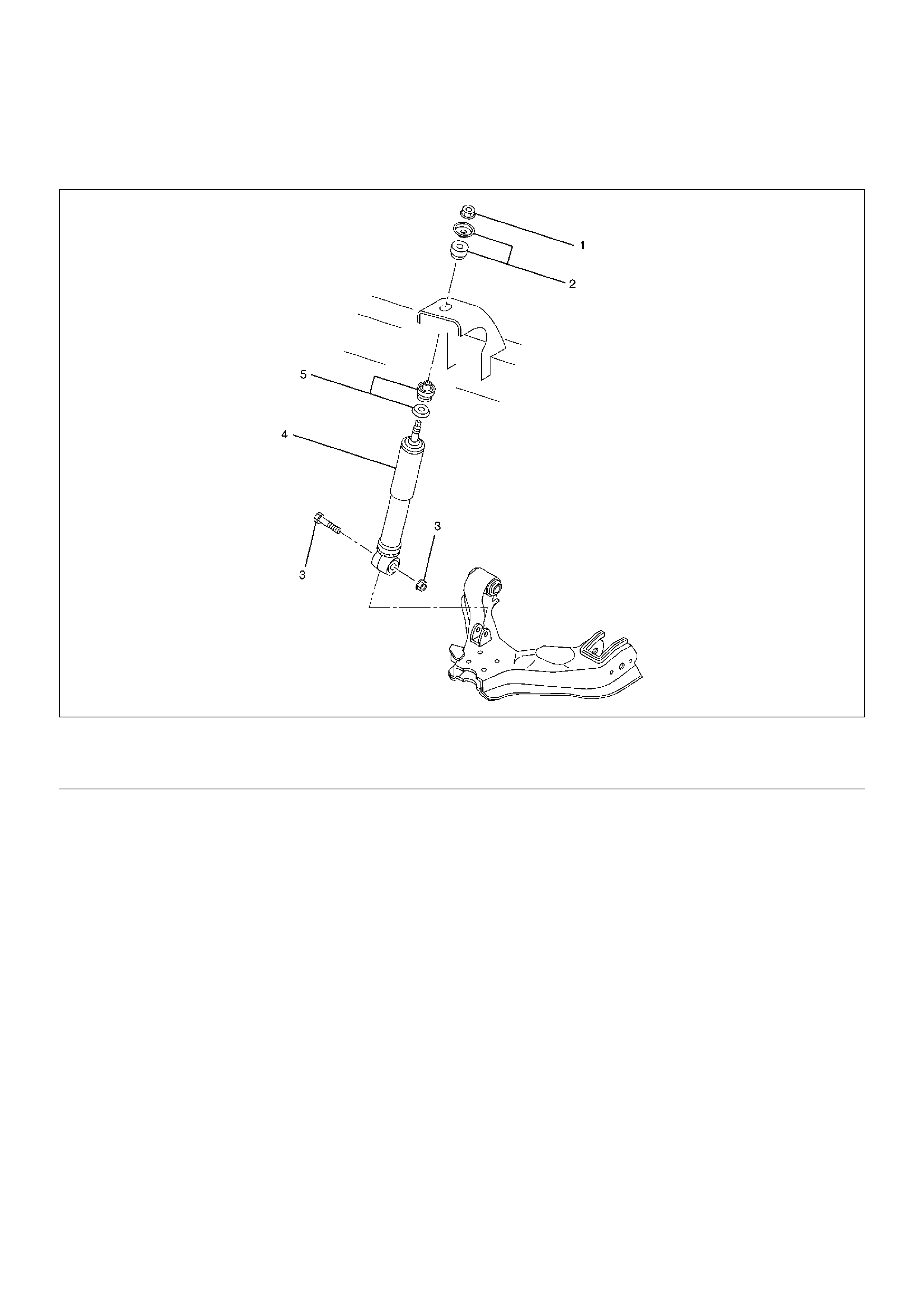
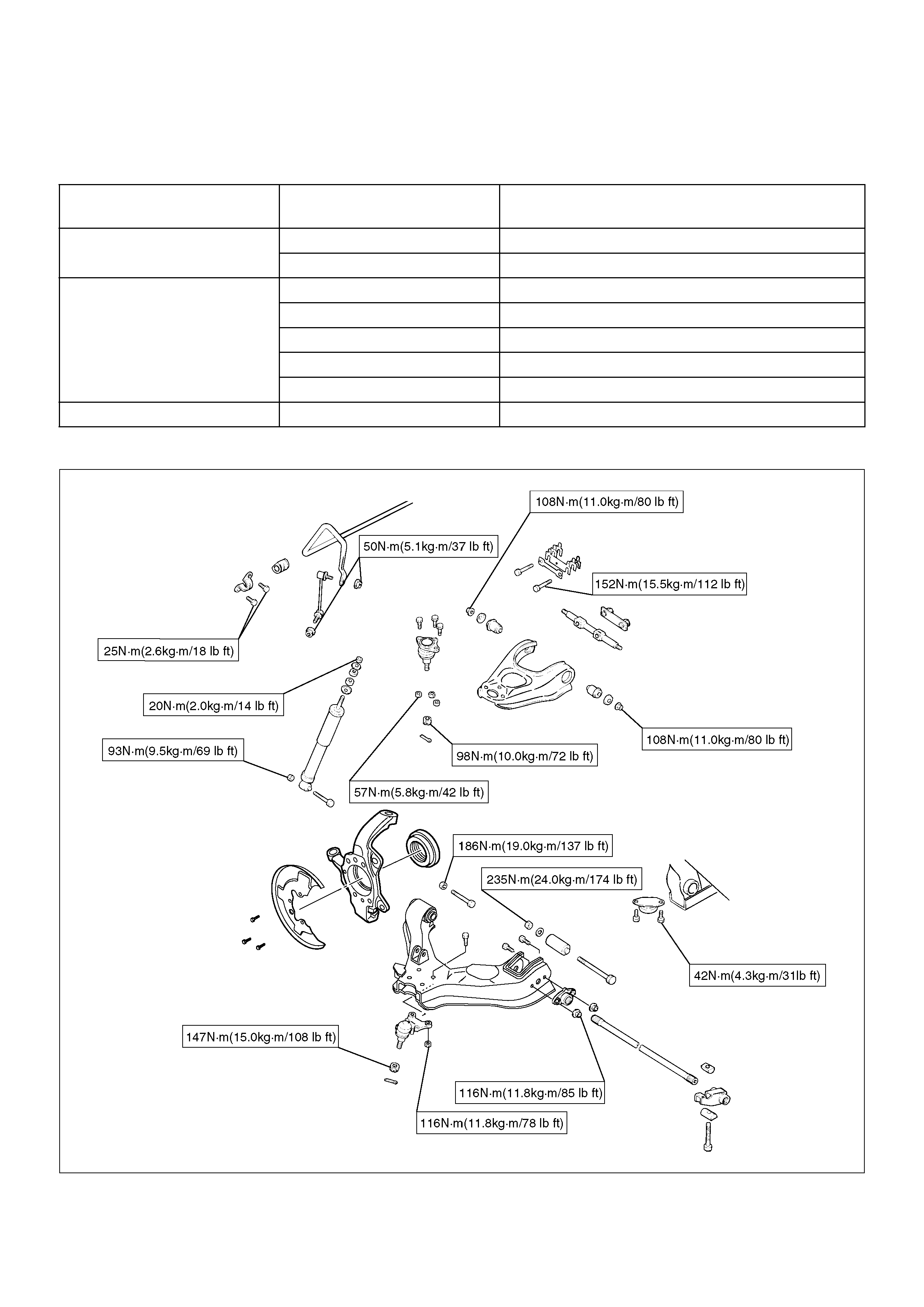
Shock Absorber
Shock Absorber and Associated Parts
4
5
0
R
W
0
0
9
EndOFCallout
Removal
1.Raise the vehicle and support it with suitable safety
stands.
2.Remove wheel and tyre assembly. Refer to Wheel
Replacement in this section.
3. Remove bolt and nut.
4. Remove nut.
5. Remove rubber bushing and washer.
6. Remove shock absorber.
7. Remove rubber bushing and washer.
Inspection and Repair
Make necessary correction or parts replacement if wear,
damage, corrosion or any other abnormal condition are
found through inspection.
Check the following parts :
• Shock absorber
• Rubber bushing
Installation
1. Install rubber bushing and washer.
2. Install shock absorber.
3. Install rubber bushing and washer.
4. Install nut, then tighten it to the specified torque.
Torque: 20N·m (2.0kg·m/14lbft)
5. Install bolt and nut, then tighten to the specified
torque.
Torque: 93N·m (9.5kg·m/69lbft)
Legend
(1) Nut
(2) Rubber Bushing and Washer
(3) Bolt and Nut
(4) Shock Absorber
(5) Rubber Bushing and Washer
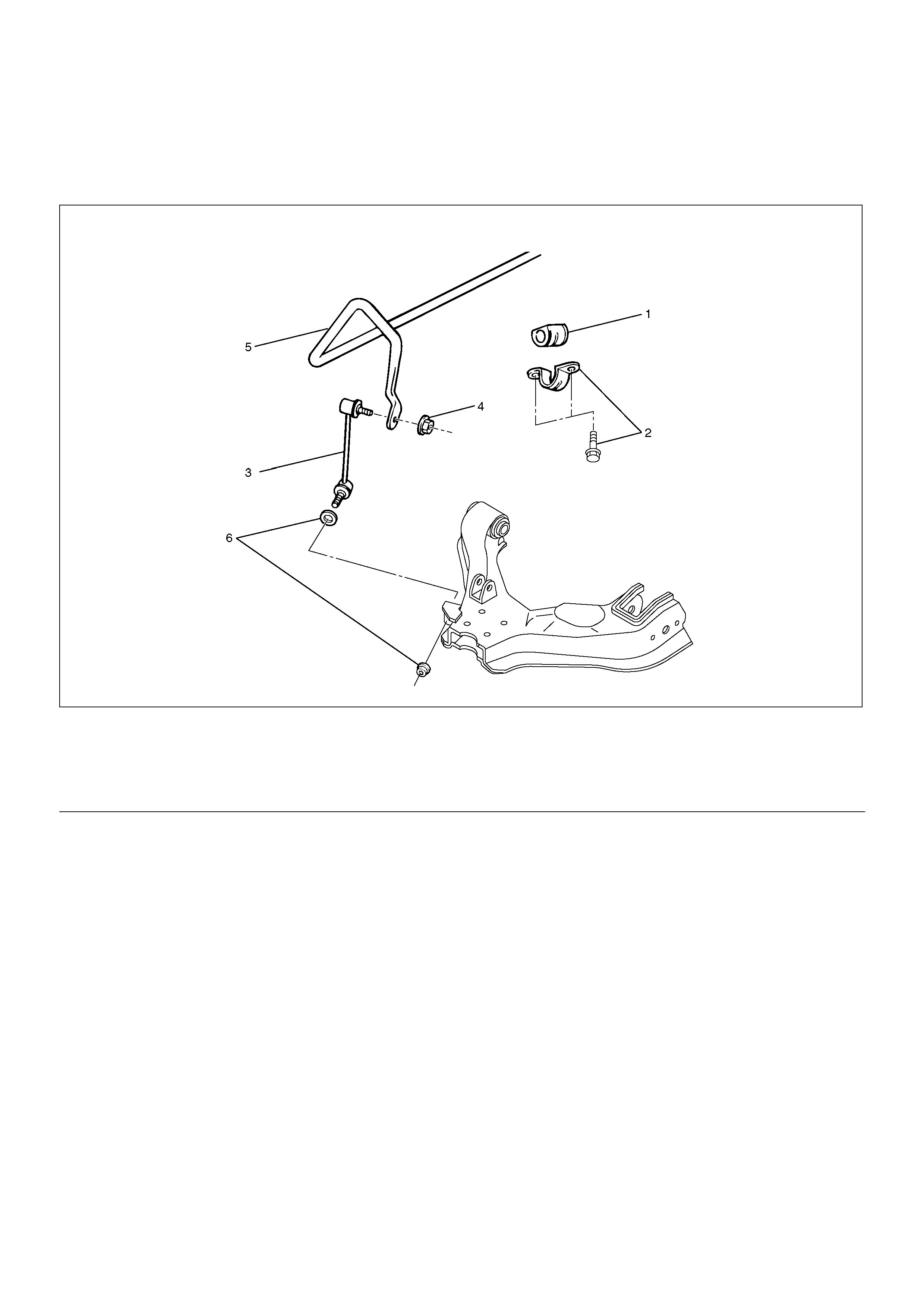
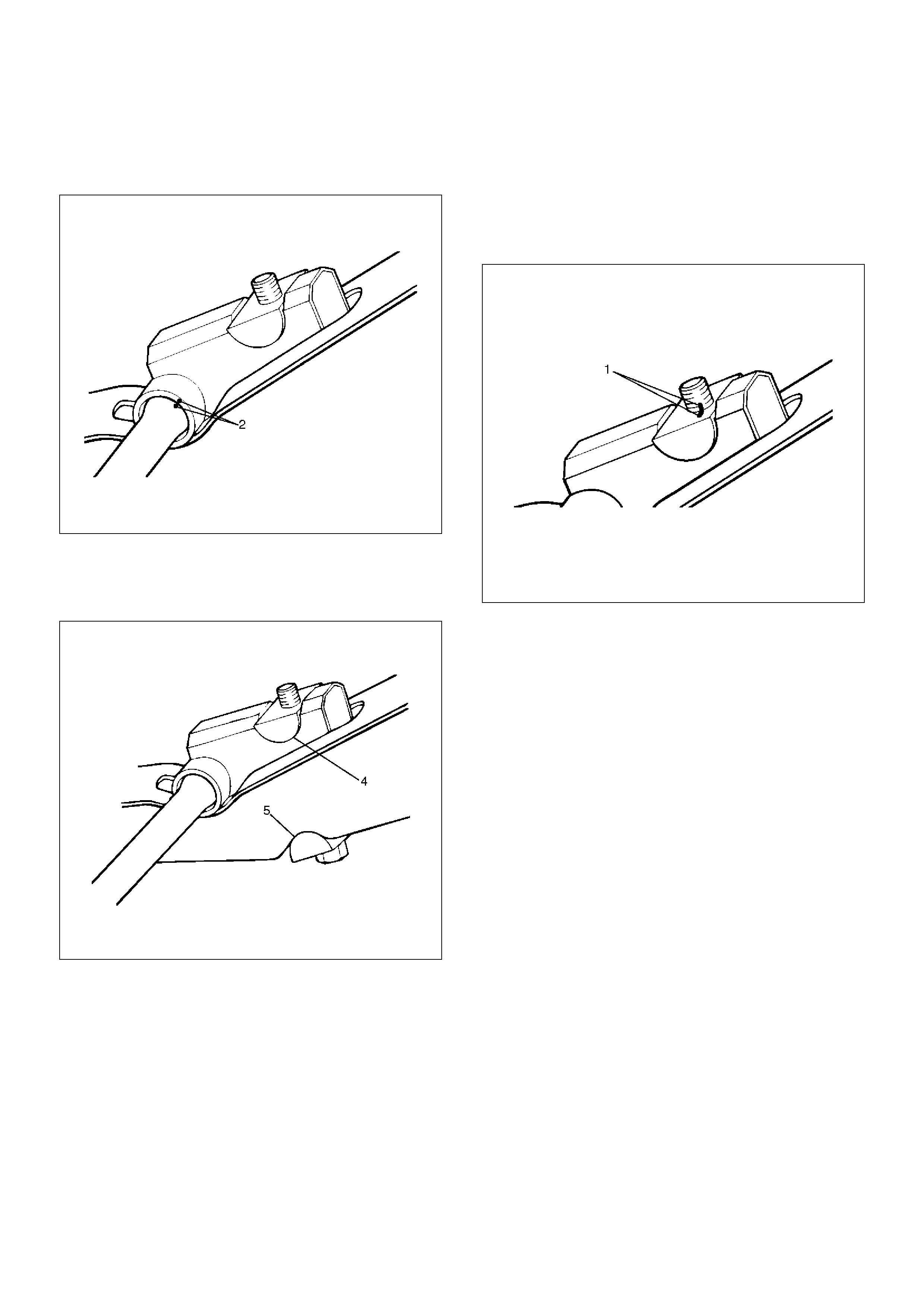
Stabilizer Bar
Stabilizer Bar and Associated Parts
410R100001
EndOFCallout
Removal
1.Raise the vehicle and support the frame with
suitable safety stands.
2.Remove the stone guard.
3.Remove wheel and tyre assembly. Refer to Wheel
Replacement in this section.
4.Remove nut (4) and (6).
CAUTION: Be careful not to break the ball joint
boot.
5. Remove link.
6. Remove bracket.
7. Remove stabilizer bar.
8. Remove rubber bushing.
Inspection and Repair
Make necessary correction or parts replacement if wear,
damage, corrosion or any other abnormal condition are
found through inspection.
Check the following parts :
• Stabilizer bar
• Rubber bushing
• Link ball joint
Installation
1. Install rubber bushing.
2. Install stabilizer bar.
3. Install bracket and bolt, then tighten it to the
specified torque.
Torque: 25N·m (2.6kg·m/18lbft)
4. Install link.
5. Install nut (4), (6) and washer, then tighten it to the
specified torque.
Torque: 50N·m (5.1kg·m/37lbft)
Legend
(1) Rubber Bushing
(2) Bracket and Bolt
(3) Link
(4) Nut
(5) Stabilizer Bar
(6) Nut and Washer
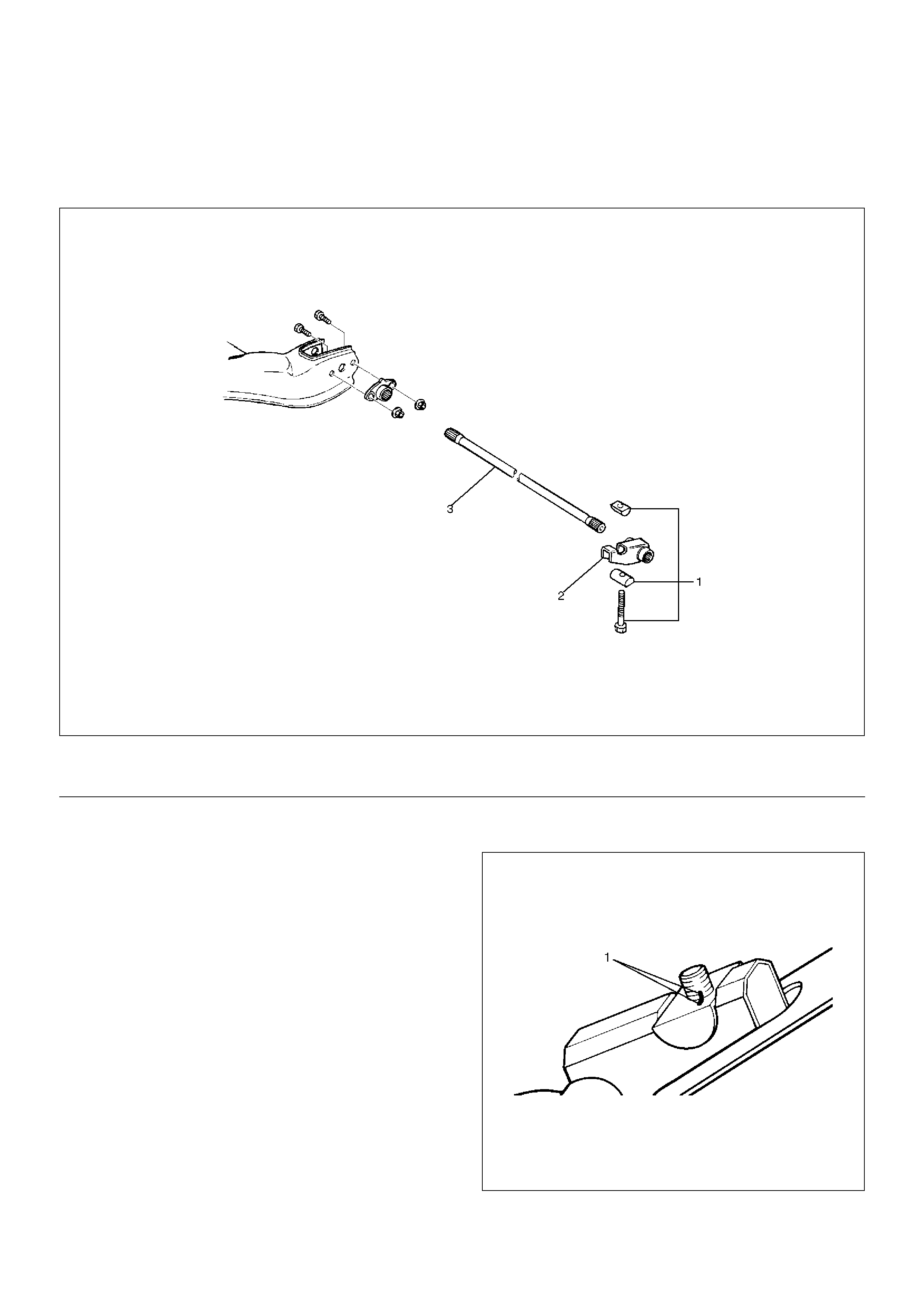
Torsion Bar
Torsion Bar and Associated Parts
410RS003
EndOFCallout
Removal
1. Raise the vehicle and support the frame with
suitable safety stands.
2. Apply the setting marks(1) to the adjust bolt and end
piece, then remove adjust bolt, end piece and seat.
410RS004
Legend
(1) Adjust Bolt, End Piece and Seat
(2) Height Control Arm
(3) Torsion Bar
3. Apply the setting marks(2) to the height control arm
and torsion bar, then remove height control arm.
410RS005
4. Apply the setting marks(3) to the torsion bar and
lower control arm, then remove torsion bar.
410RS006
Inspection and Repair
Make necessary correction or parts replacement if wear,
damage, corrosion or any other abnormal condition are
found through inspection.
Check the following parts:
• Torsion bar
• Height control arm
• Adjust bolt
• Rubber seat
Installation
1. Apply grease to the serrated portions, then install
torsion bar. Make sure the bars are on their correct
respective sides and align the setting marks(3).
410RS007
410RS006
2.Apply grease to the portion that fits into the bracket
then install height control arm and align the setting
marks(2).
410RS005
3.Apply grease to the bolt portion of the end piece(4).
Apply grease to the portion of the seat(5) that fits
into the bracket.
410RS008
4.Apply grease to the serrated portions.
5.Install adjust bolt and seat, then turn the adjust bolt
to the setting mark(1) applied during disassembly.
NOTE: Adjust the trim height. Refer to Front End
Alignment Inspection and Adjustment in Steering
section.
410RS004
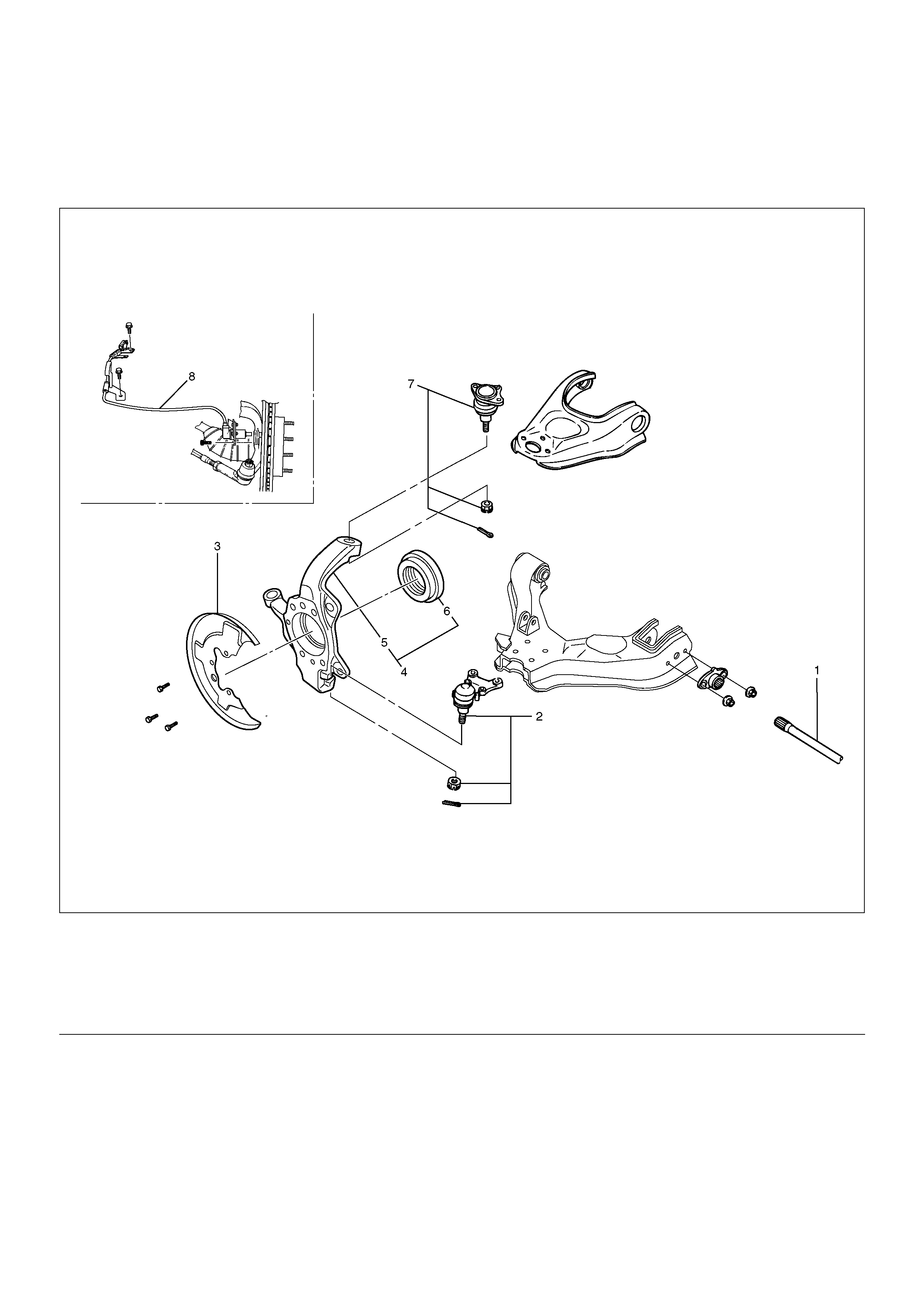
Knuckle
Knuckle and Associated Parts
410R200002
EndOFCallout
Removal
1.Raise the vehicle and support the frame with
suitable safety stands.
2.Remove wheel and tyre assembly.
3.Remove the brake caliper. Refer to Disc Brakes in
Brake section.
4.Remove the disk rotor. Refer to Disc Brakes in
Brake section.
5.Remove the hub assembly. Refer to Front Hub and
Disc in this section.
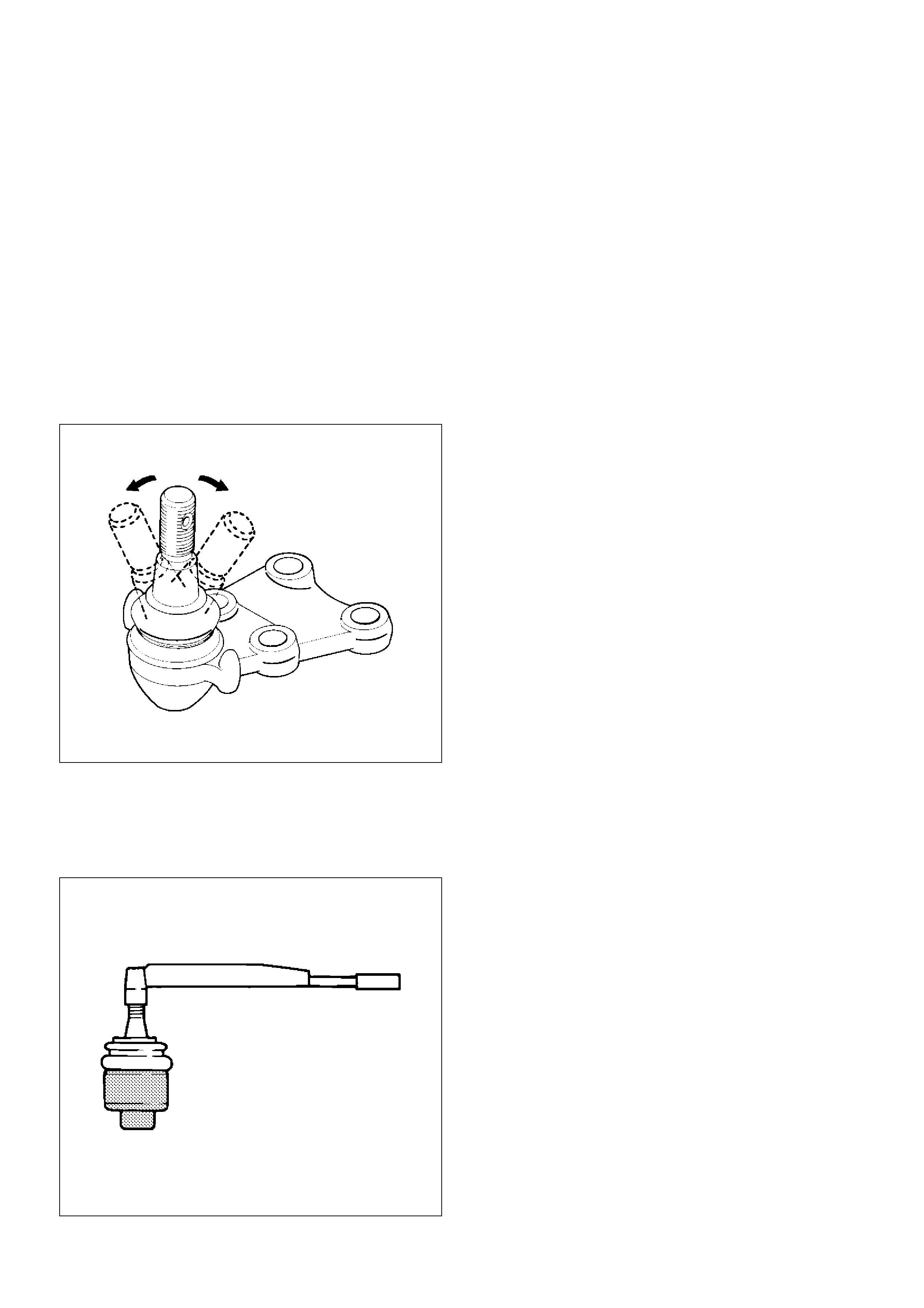
6.Remove tie–rod end from the knuckle. Refer to
Power Steering.
7. Remove the speed sensor from the knuckle.
Legend
(1) Torsion Bar
(2) Lower Ball Joint, Nut and Cotter Pin
(3) Back Plate
(4) Knuckle Assembly
(5) Knuckle
(6) Oil Seal
(7) Upper Ball Joint, Nut and Cotter Pin
(8) Wheel Speed Sensor
8.Loosen torsion bar by height control arm adjust bolt,
then remove torsion bar. Refer to Torsion Bar in this
section.
9.Remove wheel speed sensor.
10.Remove back plate.
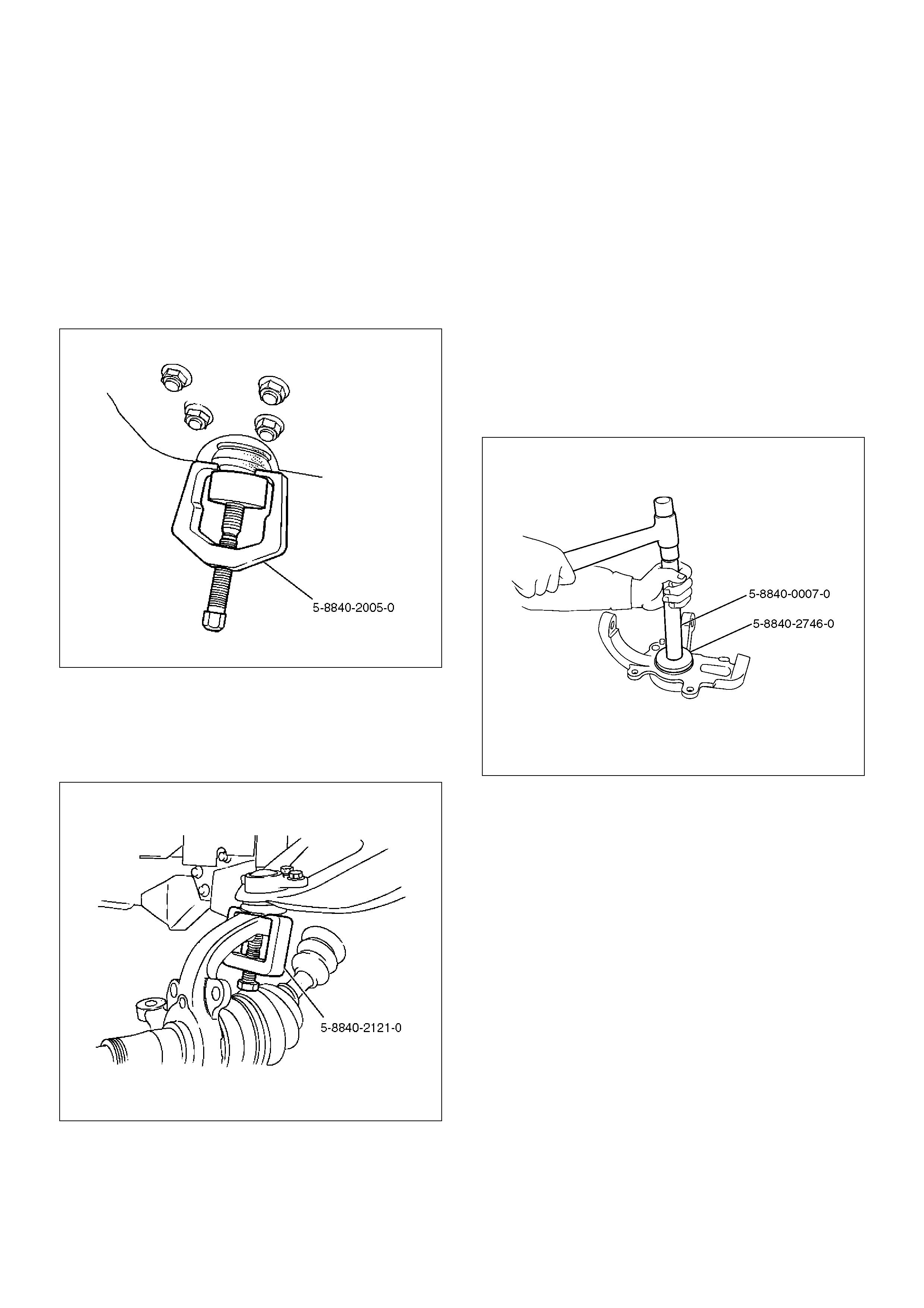
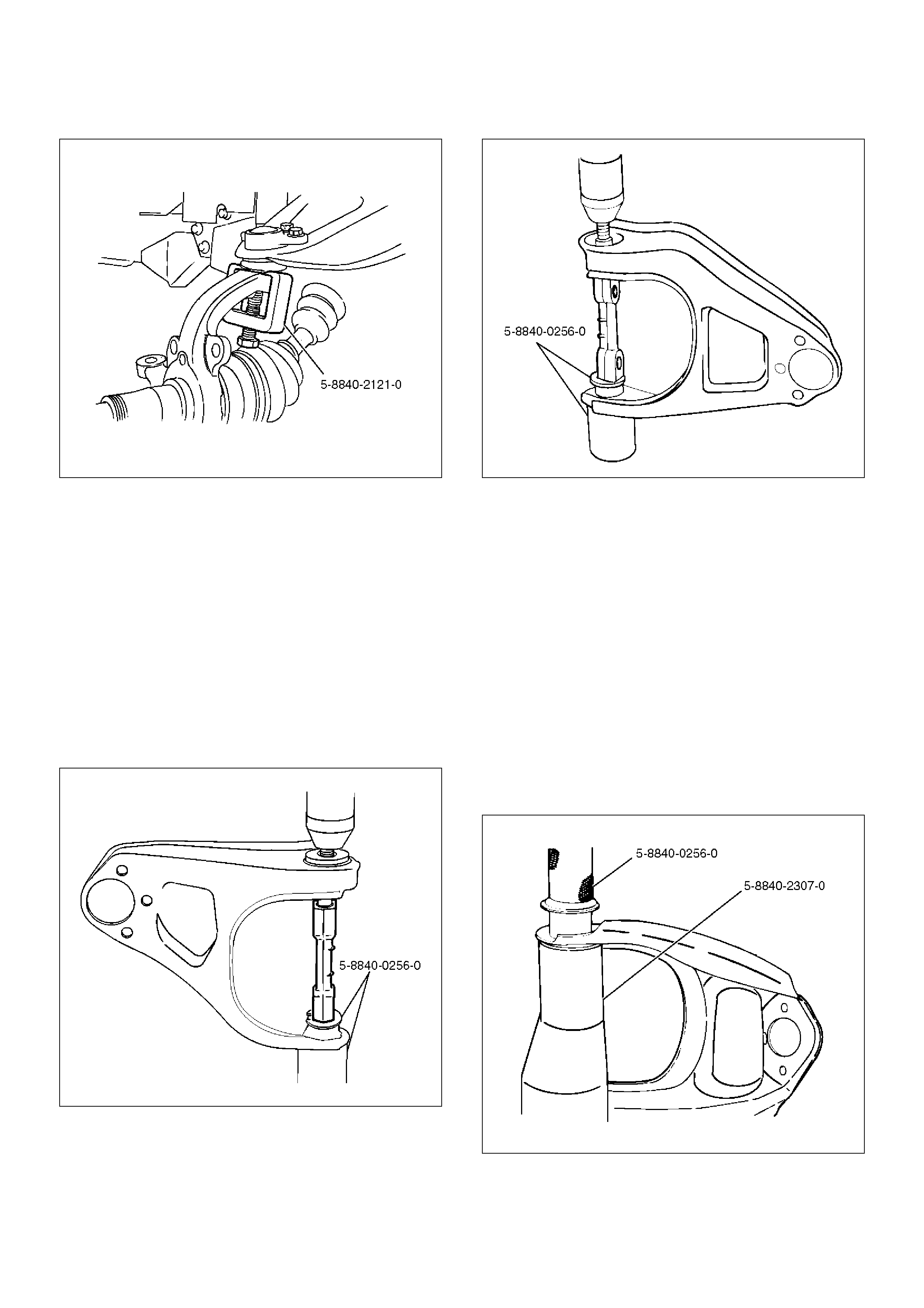
11.Remove lower ball joint by using remover 5–8840–
2005–0.
CAUTION: Be careful not to damage the ball joint
boot.
901RW271
12.Remove upper ball joint by using remover 5–8840–
2121–0.
CAUTION: Be careful not to damage the ball joint
boot.
901RW273
13.Remove knuckle assembly.
14.Remove oil seal.
Inspection and Repair
Make necessary correction or parts replacement if wear,
damage, corrosion or any other abnormal condition are
found through inspection.
Check the following parts:
•Knuckle
•Knuckle arm
Installation
1.Use a new oil seal, and apply multipurpose type
grease to the area surrounded by the lip (approx. 2
g). Then use installer 5–8840–2746–0 and grip 5–
8840–0007–0 to install oil seal. After fitting the oil
seal to the installer, drive it to the knuckle using a
hammer or bench press.
901R200031
2.Install knuckle assembly.
3.Install upper ball joint and tighten the nut to the
specified torque, with just enough additional torque
to align cotter pin holes. Install new cotter pin.
Torque: 98N·m (10.0kg·m/72lbft)
4.Install lower ball joint and tighten the nut to the
specified torque, with just enough additional torque
to align cotter pin holes. Install new cotter pin.
Torque: 147N·m (15.0kg·m/108lbft)
5.Install back plate.
6.Install wheel speed sensor.
7.Install torsion bar, refer to Torsion Bar in this
section.
NOTE: Adjust the trim height. Refer to Front End
Alignment Inspection and Adjustment in Steering.
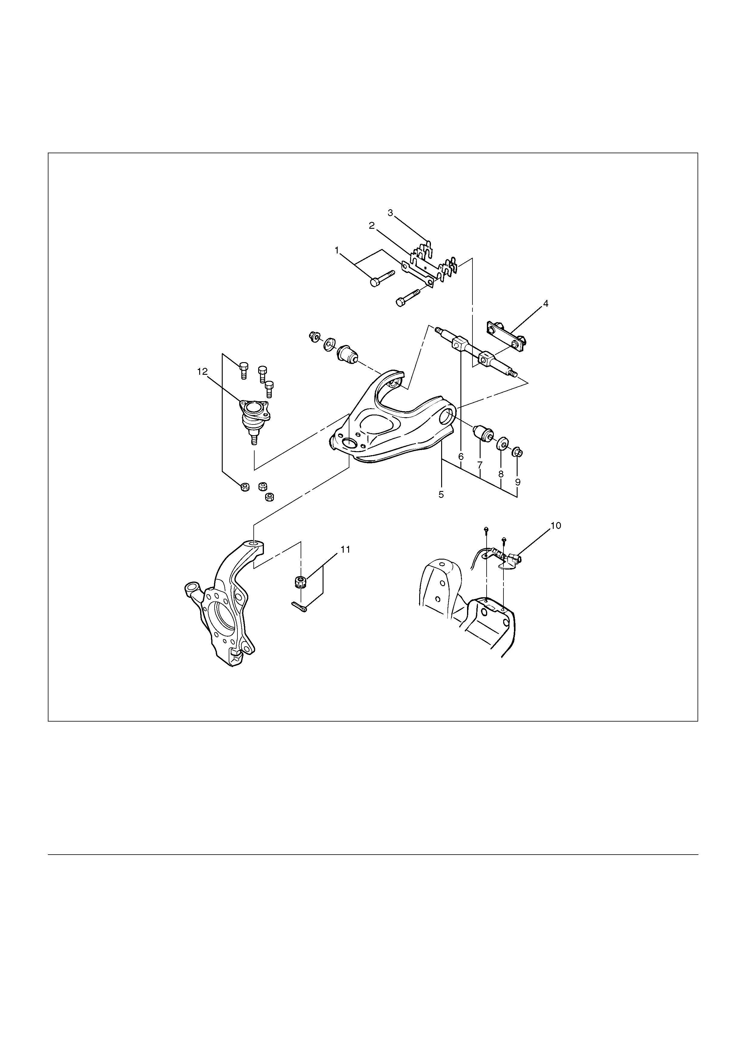
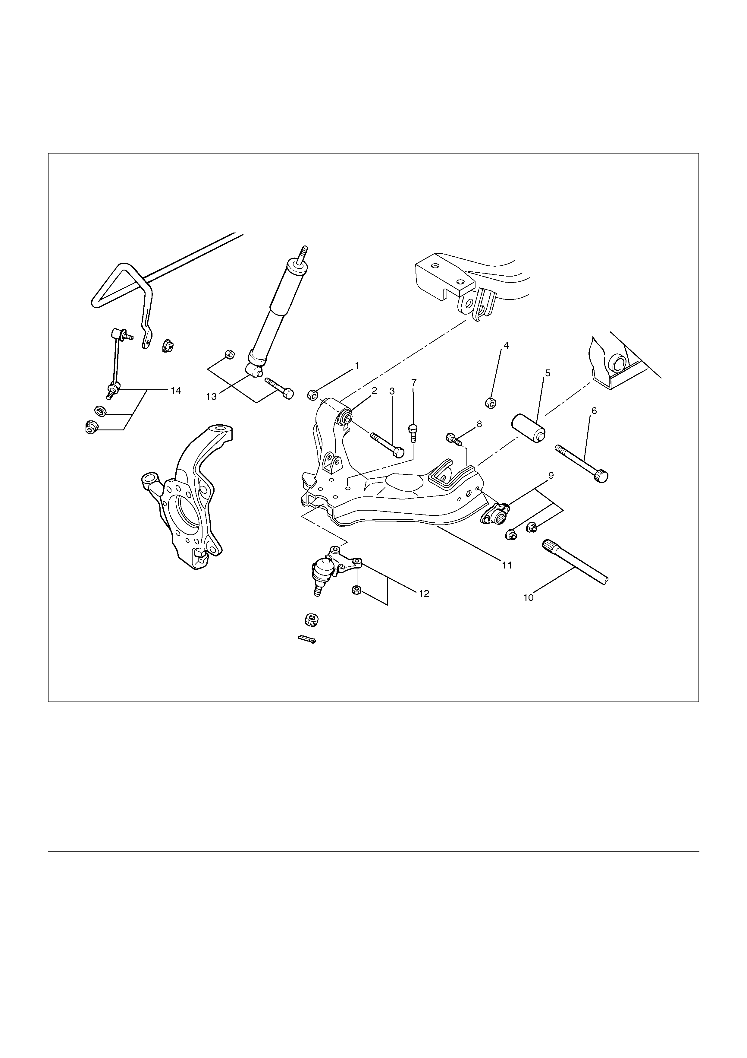
Upper Control Arm
Upper Control Arm and Associated Parts
450R200005
EndOFCallout
Removal
1.Raise the vehicle and support the frame with
suitable safety stands.
2.Remove wheel and tyre assembly. Refer to Wheel
in this section.
3.Remove the brake caliper and disconnect brake
pipe. Refer to Disc Brakes in Brake section.
4.Support lower control arm with a jack.
5.Remove speed sensor cable.
6.Remove nut and cotter pin then remove knuckle
using remover 5–8840–2121–0.
CAUTION: Be careful not to damage the ball joint
boot.
Legend
(1) Bolt and Plate
(2) Camber Shims
(3) Caster Shims
(4) Nut Assembly
(5) Upper Control Arm Assembly
(6) Fulcrum Pin
(7) Bushing
(8) Plate
(9) Nut
(10) Speed Sensor Cable
(11) Nut and Cotter Pin
(12) Upper Ball Joint, Bolt and Nut
901RW273
7. Remove upper ball joint.
8. Remove bolt and plate.
9. Remove nut assembly.
10. Remove camber shims and note the positions and
number of shims.
11. Remove caster shims and note the positions and
number of shims.
12. Remove upper control arm assembly.
13. Remove nut (9).
14. Remove plate (8).
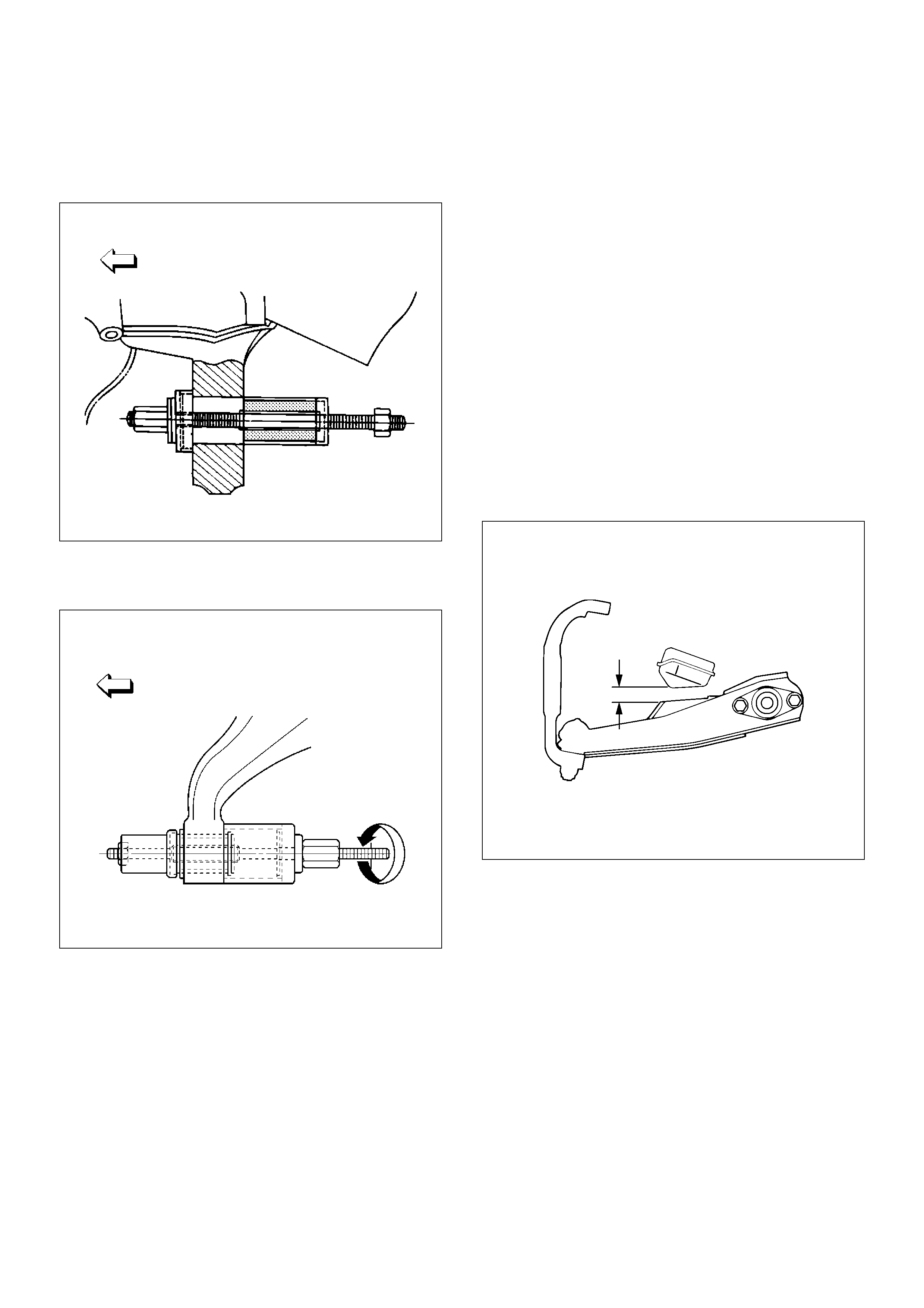
15. Remove bushing (7) by using remover 5–8840–
0256–0.
901RW277
901RW276
16. Remove fulcrum pin (6).
Inspection and Repair
Make necessary parts replacement if wear, damage,
corrosion or any other abnormal conditions are found
through inspection.
Check the following parts:
• Upper control arm
• Bushing
• Fulcrum pin
Installation
1. Install fulcrum pin.
2. Install bushing by using installer 5–8840–0256–0
and 5–8840–2307–0.
901RW278
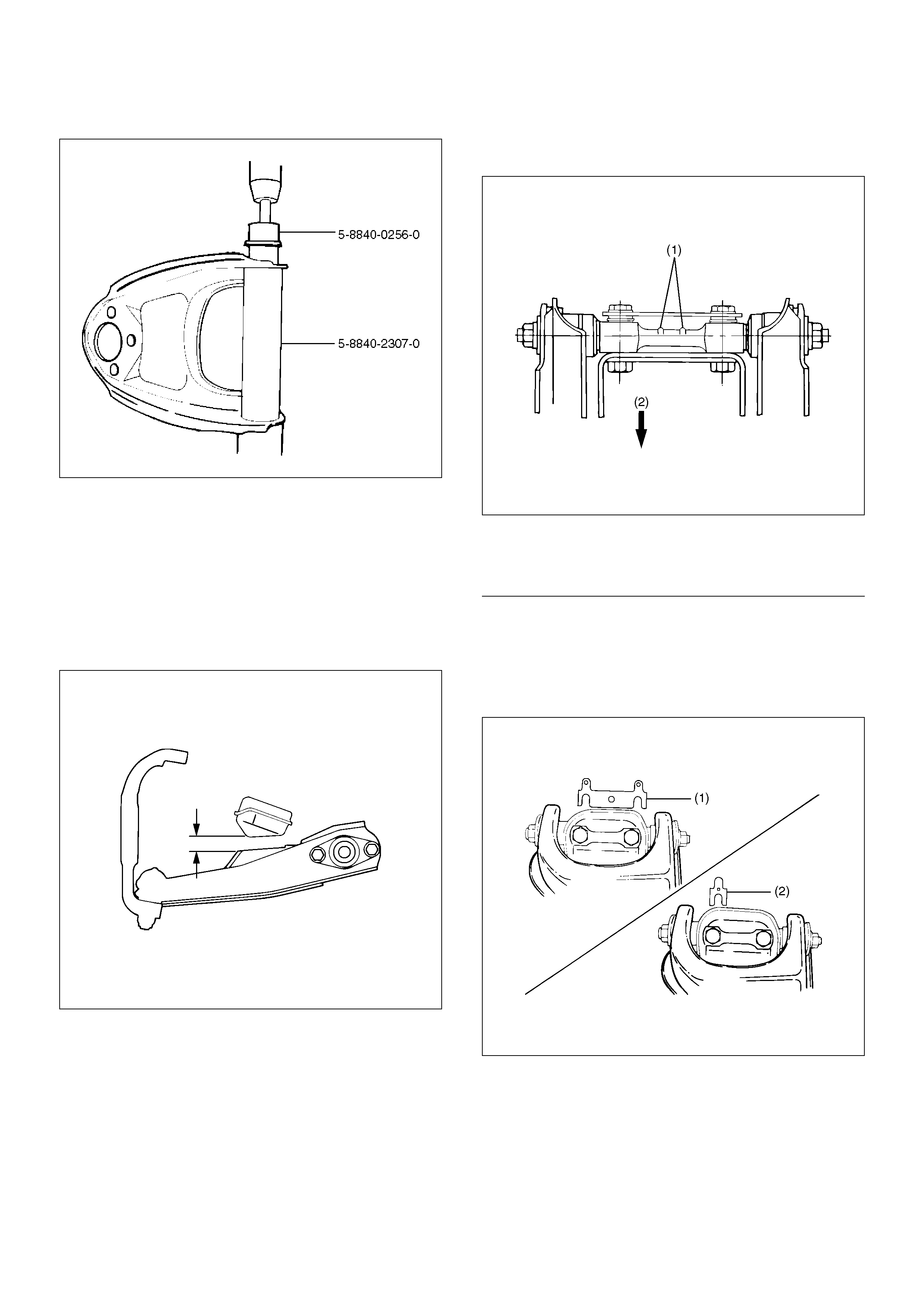
901RW279
3. Install plate (8).
4. Install nut (9) and tighten fulcrum pin nut finger–
tight.
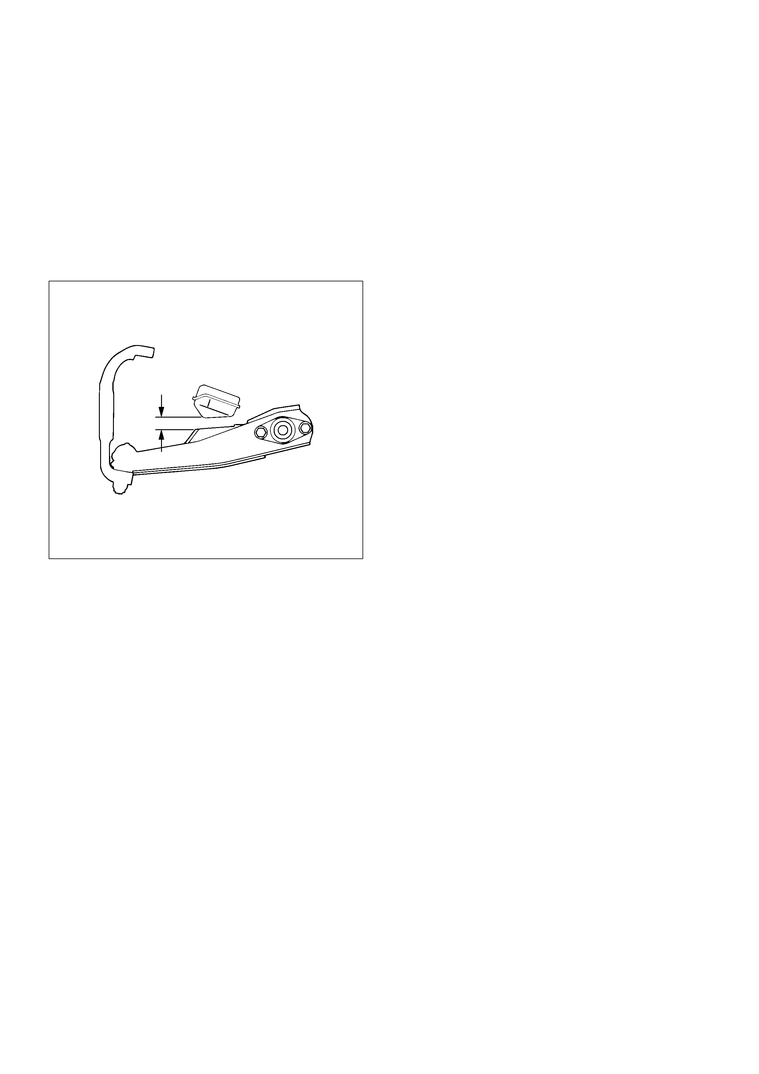
NOTE: Torque fulcrum pin nut after adjusting buffer
clearance.
Buffer clearance: 22mm (0.87in)
Torque: 108N·m (11.0kg·m/80lbft)
450R200009
5. Install upper control arm assembly with the fulcrum
pin projections turned inward.
450R100003
EndOFCallout
6. Install the caster shims(2) between the chassis
frame and fulcrum pin.
7. Install the camber shims(1) between the chassis
frame and fulcrum pin.
450R100004
Legend
(1) Projection
(2) Outward

8. Install nut assembly.
9. Install bolt and plate, then tighten the bolt to the
specified torque.
Torque: 152N·m (15.5kg·m/112lbft)
10. Install upper ball joint and tighten it to the specified
torque.
Torque: 57N·m (5.8kg·m/42lbft)
11. Install nut and cotter pin then tighten the nut to the
specified torque, with just enough additional torque
to align cotter pin holes. Install new cotter pin.
Torque: 98N·m (10.0kg·m/72lbft)
12. Install speed sensor cable.
Lower Control Arm
Lower Control Arm and Associated Parts
450R200006
EndOFCallout
Removal
1.Raise the vehicle and support the frame with
suitable safety stands.
2.Remove wheel and tyre assembly. Refer to Wheel
in this section.
3.Remove the tie-rod end from the knuckle. Refer to
Power Steering Unit in Steering section.
4.Remove the retaining ring from the front axle driving
shaft to release the shaft from hub. Refer to Front
Hub and Disc in Driveline/Axle section.
5.Support lower control arm with a jack.
6.Remove front nut.
7.Remove rear nut.
8.Remove torsion bar, refer to Torsion Bar in this
section.
Legend
(1) Nut, Front
(2) Bush, Front
(3) Bolt, Front
(4) Nut, Rear
(5) Bush, Rear
(6) Bolt, Rear
(7) Bolt, Lower Ball Joint
(8) Bolt, Torsion Bar Arm
(9) Torsion Bar Arm Bracket and Nut
(10) Torsion Bar
(11) Lower Control Arm
(12) Lower Ball Joint and Nut
(13) Shock Absorber, Bolt and Nut
(14) Stabilizer Link, Washer and Nut
9. Remove torsion bar arm bracket.
10. Disconnect the stabilizer link at the lower control
arm.
11. Remove the shock absorber lower end from the
lower control arm.
12. Remove the lower ball joint from the lower control
arm.
13. Remove front bolt.
14. Remove rear bolt.
15. Remove lower control arm.
16. Remove torsion bar arm bolt.
17. Remove lower ball joint bolt.
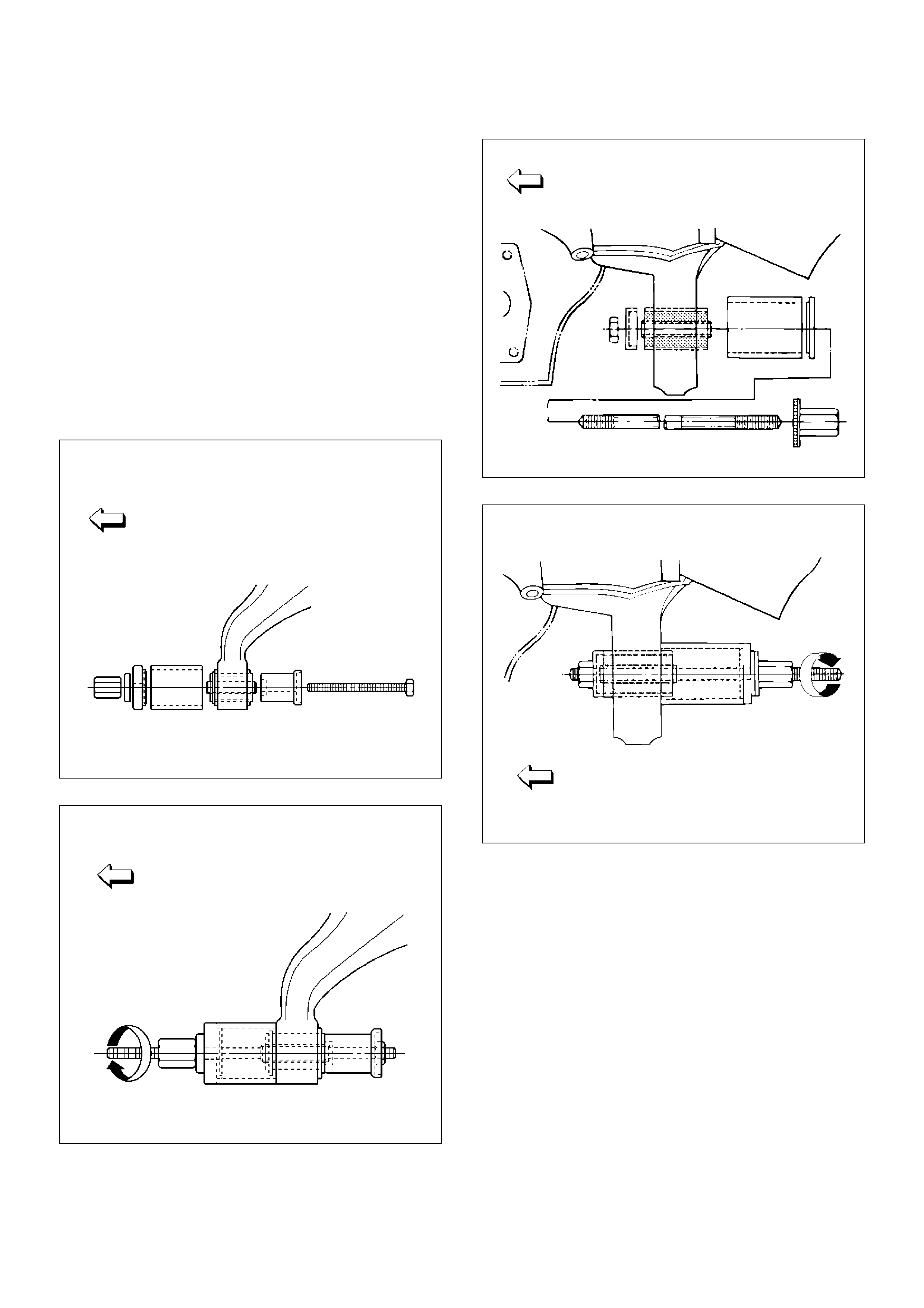
18. Remove front bushing by using remover 5–8840–
2123–0.
901RW154
901RW155
19. Remove rear bushing by using remover 5–8840–
2124–0.
901RW051
901RW052
Inspection and Repair
Make necessary correction or parts replacement if wear,
damage, corrosion or any other abnormal condition are
found through inspection.
Check the following parts:
• Lower control arm
• Bushing
Installation
1.Install rear bushing by using installer 5–8840–2124–
0.
901RW053
2.Install front bushing by using installer 5–8840–
2123–0.
901RW156
3.Install lower ball joint bolt.
4.Install torsion bar arm bolt.
5.Install lower control arm.
6.Install rear bolt.
7.Install front bolt.
8.Install lower ball joint and tighten it to the specified
torque.
Torque: 116N·m (11.8kg·m/85lbft)
9.Install shock absorber and tighten it to the specified
torque.
Torque: 93N·m (9.5kg·m/69lbft)
10.Install stabilizer link and tighten it to the specified
torque.
Torque: 50N·m (5.1kg·m/37lbft)
11.Install torsion bar arm bracket and tighten it to the
specified torque.
Torque: 116N·m (11.8kg·m/85lbft)
12.Install Torsion bar, refer to Torsion Bar in this
section.
13. Install rear nut and tighten lower link nut finger–tight.
NOTE: Torque lower control arm nut after adjusting
buffer clearance.
Buffer clearance: 22mm (0.87in)
Torque: 235N·m (24.0kg·m/174lbft)
450R200009
14.Install front nut then tighten lower link nut
finger-tight.
NOTE: Torque lower control arm nut after adjusting
buffer clearance .
Buffer clearance: 22mm (0.87in)
Torque: 186N·m (19.0kg·m/137lbft)
NOTE: Adjust the trim height. Refer to Front End
Alignment Inspection and Adjustment in Steering
section.
450R200009
Upper Ball Joint
Upper Ball Joint and Associated Parts
450R200007
EndOFCallout
Removal
1. Raise the vehicle and support the frame with
suitable safety stands.
2. Remove the speed sensor from the knuckle.
Legend
(1) Bolt and Nut
(2) Upper Ball Joint
(3) Nut and Cotter Pin
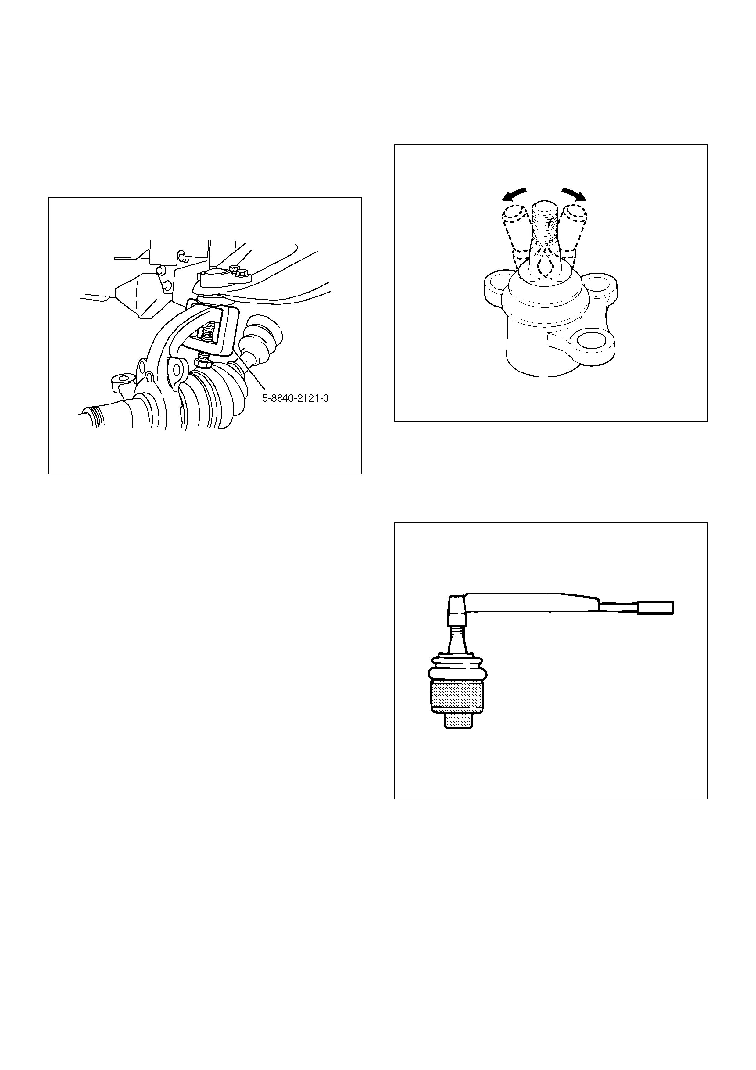
3.Remove upper ball joint nut and cotter pin, then use
remover 5–8840–2121–0 to remove the upper ball
joint from the knuckle.
CAUTION: Be careful not to damage the ball joint
boot.
901RW273
4. Remove bolt and nut.
5. Remove upper ball joint.
Inspection and Repair
Make necessary parts replacement if wear, damage,
corrosion or any other abnormal conditions are found
through inspection.
• Inspect the lower end boot for damage or grease
leak. Move the ball joint as shown in the figure to
confirm its normal movement.
• Inspect screw/taper area of ball for damage.
• If any defects are found by the above inspections,
replace the ball joint assembly with new one.
450RS023
• After moving the ball joint 4 or 5 times, attach nut
then measure the preload.
Starting torque: 0.5 –3.2N·m (0.05–0.33kg·m/0.4–
2.4lbft)
450RS024
If the above limits specified are exceeded, replace the
ball joint assembly.
Installation
1. Install upper ball joint.
2. Install bolt and nut, then tighten them to the
specified torque.
Torque: 57N·m (5.8kg·m/42lbft)
3. Install nut and cotter pin, then tighten the nut to the
specified torque with just enough additional torque
to align cotter pin holes. Install new cotter pin.
Torque: 98N·m (10.0kg·m/72lbft)
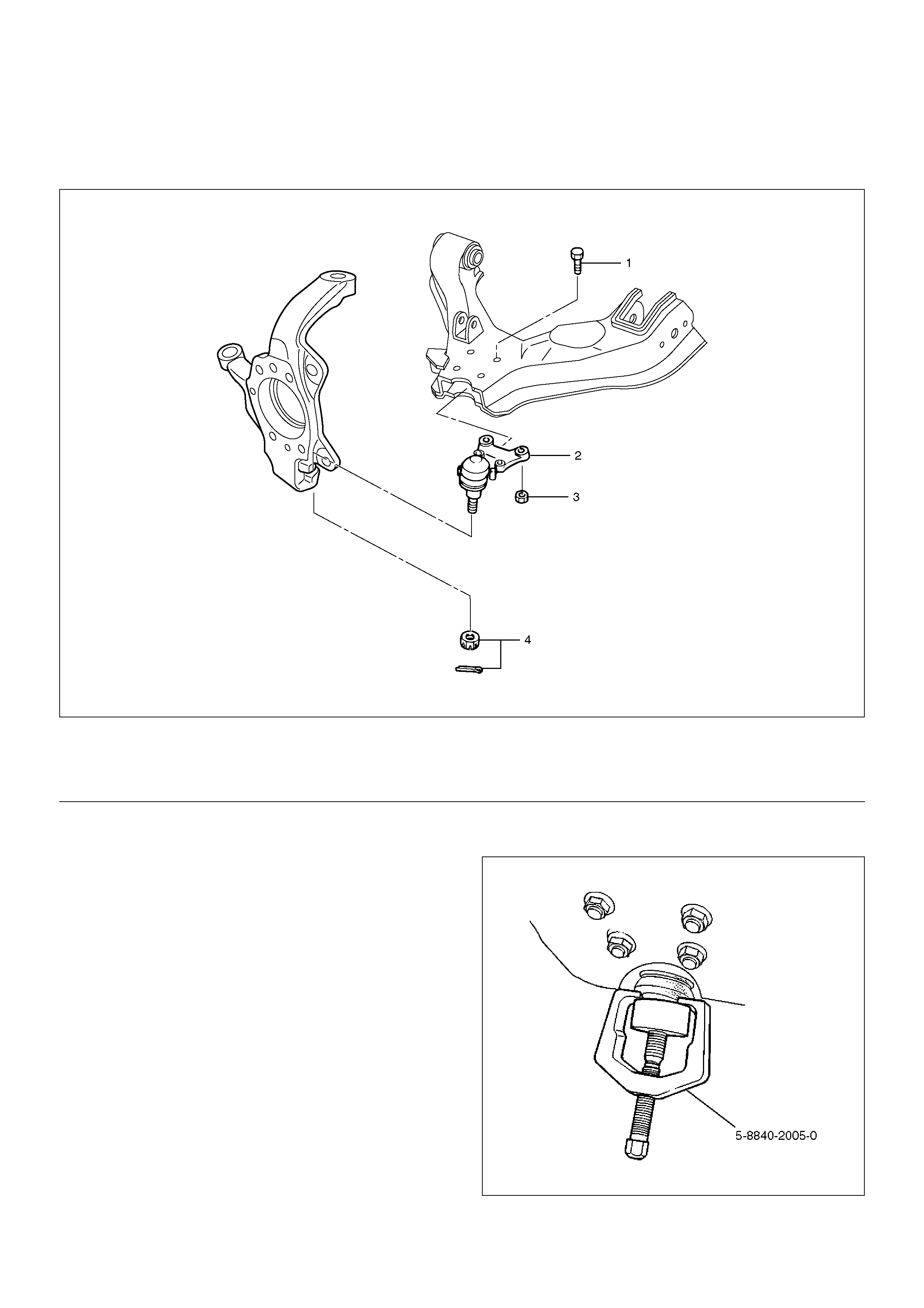
Lower Ball Joint
Lower Ball Joint and Associated Parts
450R200008
EndOFCallout
Removal
1.Raise the vehicle and support the frame with
suitable safety stands.
2.Remove wheel and tyre assembly. Refer to Wheel
in this section.
3.Remove the tie-rod end from the knuckle. Refer to
Power Steering Unit in Steering section.
4.Remove the retaining ring from the front axle driving
shaft to release the shaft from hub. Refer to Front
Hub and Disc in Driveline/Axle section.
5.Support lower control arm with a jack.
6.Remove lower ball joint nut and cotter pin, then use
remover 5–8840–2005–0 to remove the lower ball
joint from the knuckle.
CAUTION: Be careful not to damage the ball joint
boot.
901RW271
Legend
(1) Bolt
(2) Lower Ball Joint
(3) Nut
(4) Nut and Cotter Pin
7. Remove nut.
8. Remove bolt.
9. Remove lower ball joint.
Inspection and Repair
Make necessary parts replacement if wear, damage,
corrosion or any other abnormal condition are found
through inspection.
• Inspect the lower end boot for damage or grease
leak. Move the ball joint as shown in the figure to
confirm its normal movement .
• Inspect screw/taper area of ball for damage.
• If any defects are found by the above inspections,
replace the ball joint assembly with new one.
450RS026
• After moving the ball joint 4 or 5 times, attach nut
then measure the preload.
Starting torque: 0.5–6.4N·m (0.05–0.65kg·m/0.4–
4.7lbft)
450RS024
• If the above limits specified are exceeded, replace
the ball joint assembly.
Installation
1. Install lower ball joint.
2. Install bolt.
3. Install nut and tighten it to the specified torque.
Torque: 116N·m (11.8kg·m/85lbft)
4. Install ball joint nut, then tighten it to the specified
torque with just enough additional torque to align
cotter pin holes. Install new cotter pin.
Torque: 147N·m (15.0kg·m/108lbft)
Main Data and Specifications
General Specifications
Torque Specifications
E03R200009
Front suspension Type Independent wishbone arms, torsion bar spring with
stabilizer bar.
Torsion bar spring Length 1142mm (45.0in)
Diameter 28.0 mm (1.10 in)
Front shock absorber Type Hydraulic, double acting, telescopic
Piston diameter 30.0mm (1.18in)
Stroke 125.0mm (4.92in)
Compressed length 255.0mm (10.04in)
Extended length 380.0mm (14.96in)
Stabilizer bar Diameter 24.0 mm (0.94 in)
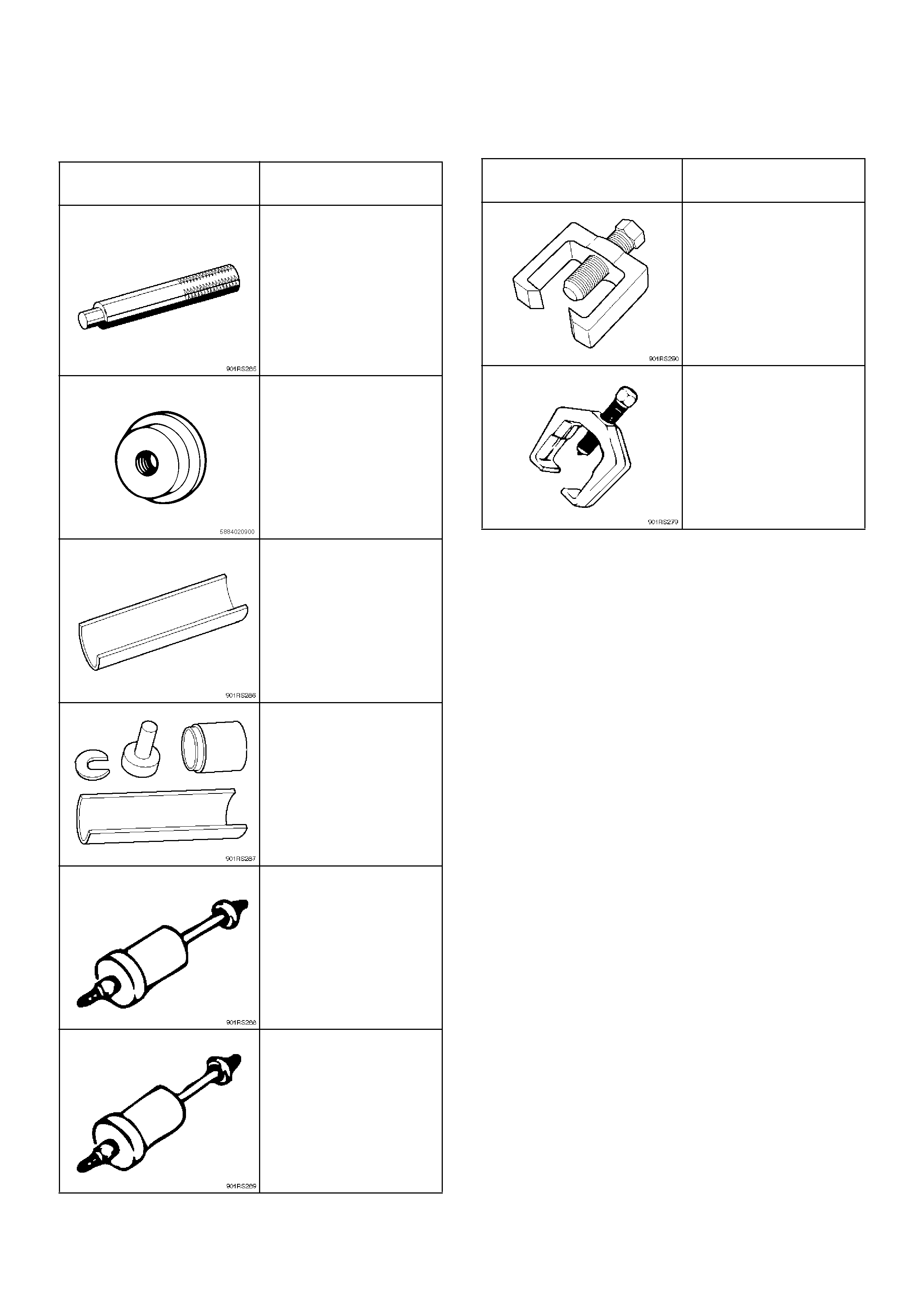
Special Tools
ILLUSTRATION TOOL NO.
TOOL NAME
5–8840–0007–0
(J–8092)
Grip
5–8840–2746–0
(J–45647)
Installer; Oil seal
5–8840–2307–0
(J–39376)
Installer; Upper arm
bushing
5–8840–0256–0
(J–29775)
Remover and Installer
Upper arm bushing
5–8840–2123–0
(J–36833)
Remover and Installer
kit;
Lower arm front bushing
5–8840–2124–0
(J–36834)
Remover and Installer
kit;
Lower arm rear bushing
5–8840–2121–0
(J–36831)
Ball joint remover
5–8840–2005–0
(J–29107)
Tie-rod end remover
ILLUSTRATION TOOL NO.
TOOL NAME