
SECTION 4A - REAR SUSPENSION (MY2002)
Service Precaution
General Description
Diagnosis
Coil Spring
Coil Spring and Associated Parts
Removal
Inspection and Repair
Installation
Shock Absorber
Shock Absorber and Associated Parts
Removal
Inspection and Repair
Installation
Trailing Link
Trailing Link and Associated Parts
Removal
Inspection and Repair
Installation
Upper Link
Upper Link and Associated Parts
Removal
Inspection and Repair
Installation
Lateral Rod
Lateral Rod and Associated Parts
Removal
Inspection and Repair
Installation
Stabiliser Bar
Stabiliser Bar and Associated Parts
Removal
Inspection and Repair
Installation
Main Data and Specifications
Special Tools
Service Precaution
WARNING: THIS VEHICLE HAS A SUPPLEMENTAL
RESTRAINT SYSTEM (SRS). REFER TO THE SRS
COMPONENT AND WIRING LOCATION VIEW IN
ORDER TO DETERMINE WHETHER YOU ARE
PERFORMING SERVICE ON OR NEAR THE SRS
COMPONENTS OR THE SRS WIRING. WHEN YOU
ARE PERFORMING SERVICE ON OR NEAR THE
SRS COMPONENTS OR THE SRS WIRING, REFER
TO THE SRS SERVICE INFORMATION. FAILURE TO
FOLLOW WARNINGS COULD RESULT IN POSSIBLE
AIR BAG DEPLOYMENT, PERSONAL INJURY, OR
OTHERWISE UNNEEDED SRS SYSTEM REPAIRS.
CAUTION: Always use the correct fastener in the
proper location. When you replace a fastener, use
ONLY the exact part number for that application.
HOLDEN will call out those fasteners that require a
replacement after removal. HOLDEN will also call
out the fasteners that require thread lockers or
thread sealant. UNLESS OTHERWISE SPECIFIED,
do not use supplemental coatings (Paints, greases,
or other corrosion inhibitors) on threaded fasteners
or fastener joint interfaces. Generally, such
coatings adversely affect the fastener torque and
the joint clamping force, and may damage the
fastener. When you install fasteners, use the correct
tightening sequence and specifications. Following
these instructions can help you avoid damage to
parts and systems.
General Description
The rear suspension is a 5-link, coil spring type
suspension with a stabiliser bar, consisting of two
trailing links, two upper links, lateral rod, shock
absorber, and stabiliser. In this suspension, the links are
specially arranged to enable the rear axle to move
freely, thereby expanding suspension stroke, reducing
friction, and improving lateral rigidity and roll control. All
these result in improved stability, riding comfort, and
rough road maneuverability.
Each link connects the axle housing with the frame
through a runner bushing. The axle housing is
supported by the trailing links and upper links
longitudinally and by the lateral rod latitudinally.
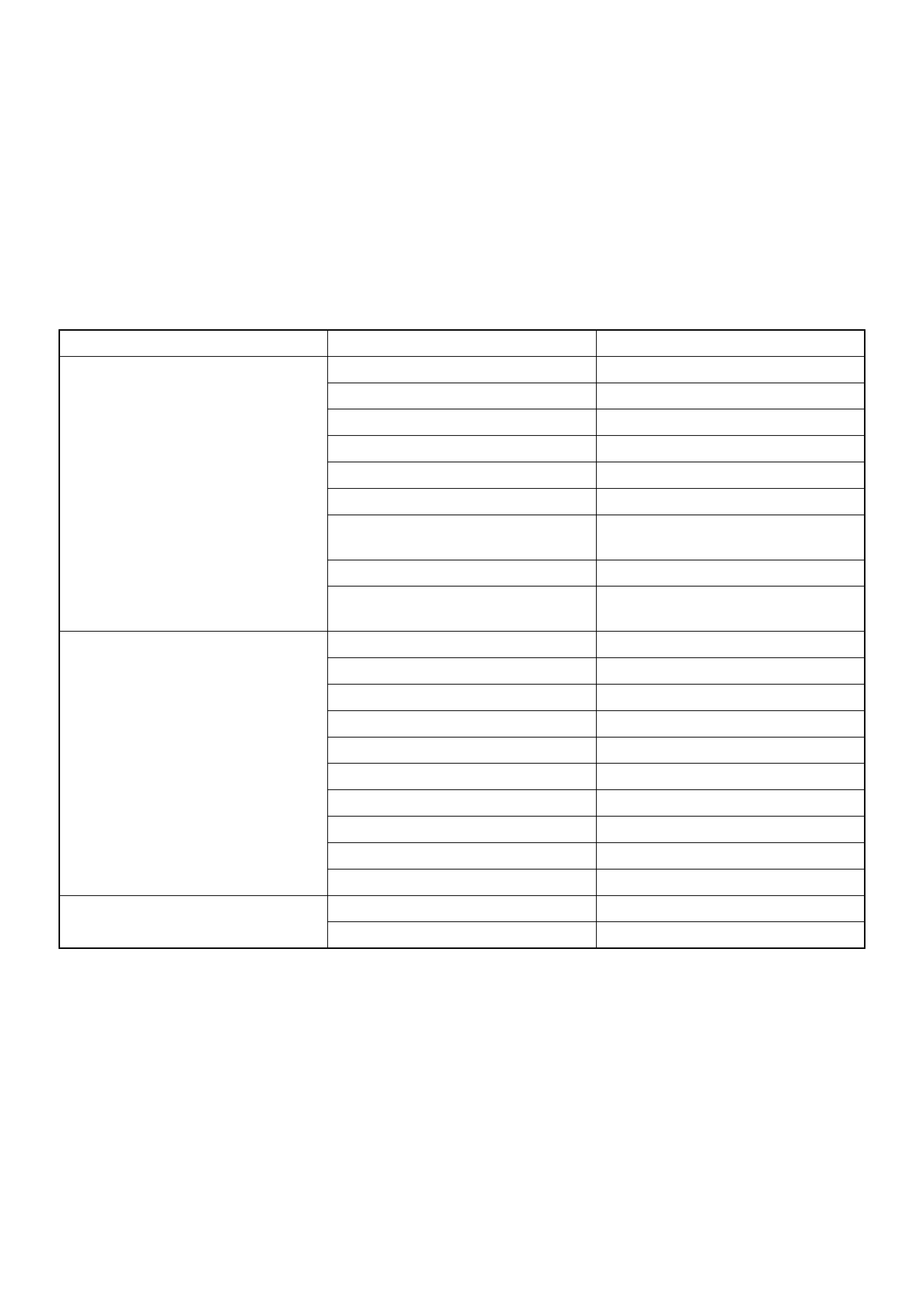
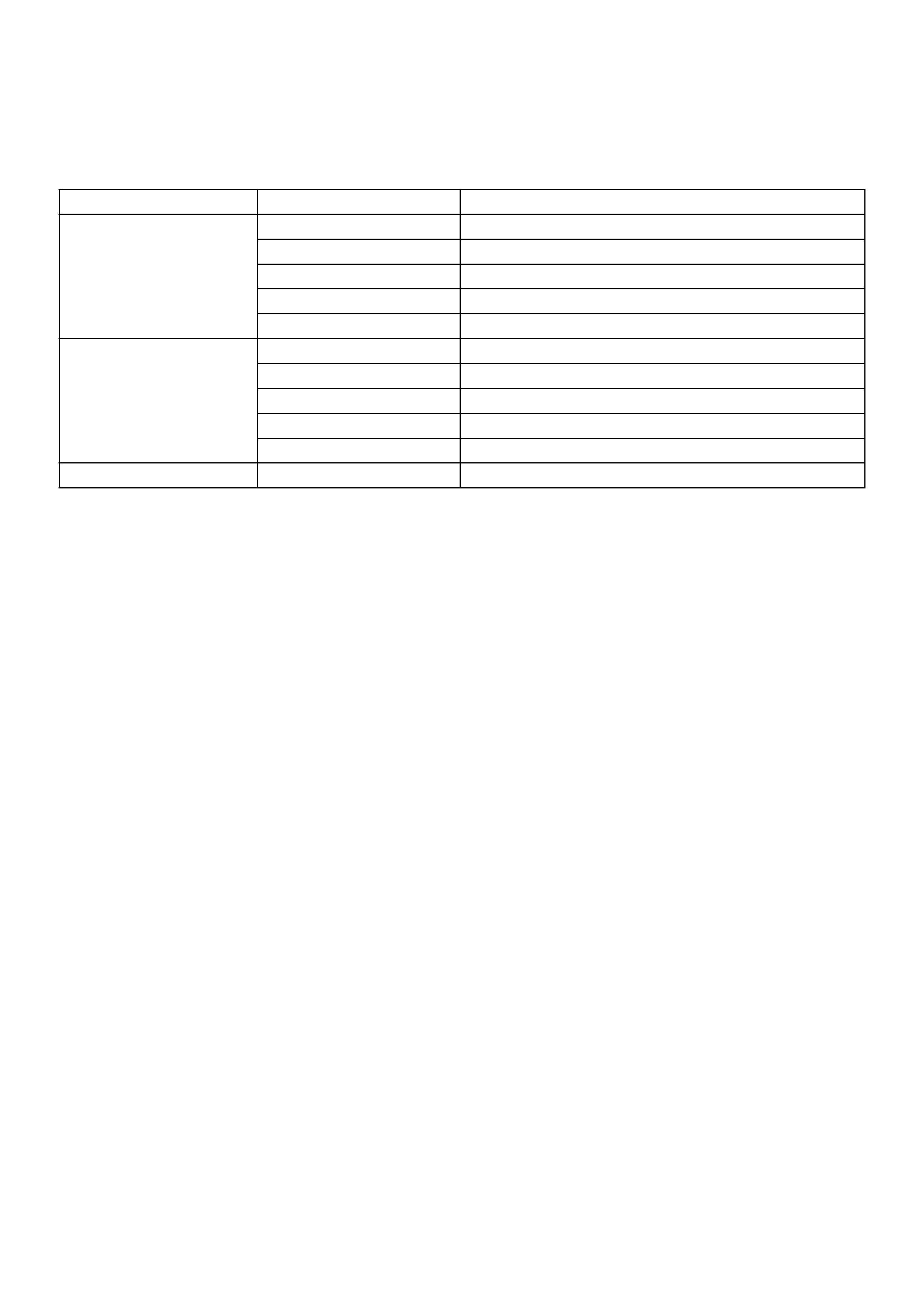
Diagnosis
Condition Possible cause Correction
Vehicle Pulls Mismatched or uneven tyres. Replace tyre.
Tyres not adequately inflated. Adjust tyre pressure.
Broken or sagging springs. Replace spring.
Radial tyre lateral force. Replace tyre.
Improper wheel alignment. Adjust wheel alignment.
Brake dragging in one wheel. Repair brake.
Loose, bent or broken front or rear
suspension parts.
Tighten or replace the appropriate
suspension part(s).
Faulty shock absorbers. Replace shock absorber.
Parts in power steering valve
defective.
Replace power steering unit.
Abnormal or Excessive Tyre Wear Sagging or broken spring. Replace spring.
Tyre out of balance. Balance or replace tyre.
Improper wheel alignment. Check front end alignment.
Faulty shock absorber. Replace shock absorber.
Hard driving. Replace tyre.
Overloaded vehicle. Replace tyre and reduce load.
Tyres not rotated periodically. Replace or rotate tyre.
Worn or loose road wheel bearings. Replace wheel bearing.
Wobbly wheel or tyres. Replace wheel or tyre.
Tyres not adequately inflated. Adjust the pressure.
Wheel Hop Blister or bump on tyre. Replace tyre.
Improper shock absorber operation. Replace shock absorber.
Shimmy, Shake or Vibration Tyre or wheel out of balance. Balance wheels or replace tyre/or
wheel.
Loose wheel bearings. Replace wheel bearing.
Worn steering linkage ball joints. Replace ball joints.
Worn upper or lower end ball joints. Replace ball joints.
Excessive wheel runout. Repair or replace wheel and/or tyre.
Blister or bump on tyre. Replace tyre.
Excessive loaded radial runout of
tyre/wheel assembly.
Replace tyre or wheel.
Improper wheel alignment. Check wheel alignment.
Loose or worn steering linkage. Tighten or replace steering linkage.
Loose steering unit. Tighten steering unit.
Tyres not adequately inflated. Adjust tyre pressure.
Loose, bent or broken front or rear
suspension parts.
Tighten or replace the appropriate
suspension parts.
Faulty shock absorber. Replace shock absorber.
Hub bearing preload misadjustment. Adjust preload.
Parts in power steering valve
defective.
Replace power steering unit.
Hard Steering Bind in steering linkage ball studs,
upper or lower ball joint.
Replace ball joint.
Improper wheel alignment. Check wheel alignment.
Tyre not adequately inflated. Inflate tyres to proper pressure.
Bind in steering column or shaft. Repair or replace.
Improper power steering system
operation.
Repair or replace. Refer to Steering
section.
Too Much Play In Steering Hub unit bearings worn. Replace hub unit bearings.
Loose steering unit or linkage. Retighten or repair.
Worn or loose steering shaft
universal joint.
Retighten or replace steering shaft.
Worn steering linkage ball joints. Replace ball joints.
Worn upper or lower end ball joints. Replace ball joints.
Poor Steering Wheel Returnability Bind in steering linkage ball joints. Replace ball joints.
Bind in upper or lower ball joints. Replace ball joints.
Bind in steering column and shaft. Repair or replace.
Bind in steering gear. Check and repair steering gear.
Improper wheel alignment. Adjust wheel alignment.
Tyres not adequately inflated. Adjust pressure.
Loose steering wheel nut. Retighten.
Worn wheel bearing. Replace.
Misassemble Transfer Gear ASM. Reassemble Transfer Gear to
proper portion.
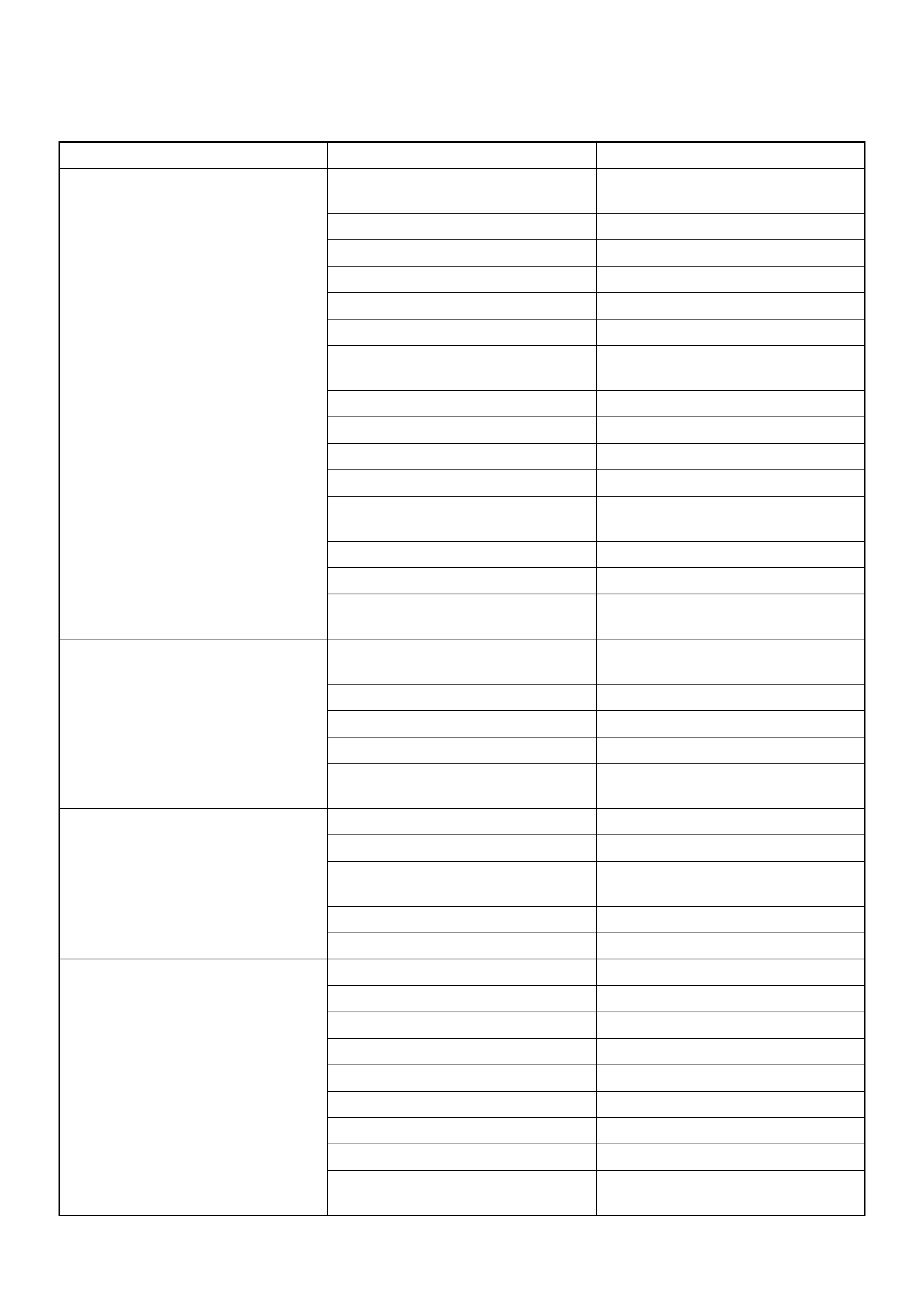
Condition Possible cause Correction
Abnormal Noise Worn, sticky or loose upper or lower
ball joint, steering linkage ball joints
or drive axle joints.
Replace.
Faulty shock absorbers. Replace.
Worn upper or lower control arm
bushing.
Replace.
Loose stabiliser bar. Retighten bolts or replace bushings.
Loose wheel nuts. Tighten nuts. Check for elongated
wheel nut holes. Replace wheel if
required.
Loose suspension bolts or nuts. Retighten suspension bolts or nuts.
Broken or otherwise damaged
wheel bearings.
Replace wheel bearing.
Broken suspension springs. Replace spring.
Loose steering unit. Retighten mounting bolt.
Faulty steering unit. Replace steering unit.
Wandering or Poor Steering Stability Mismatched or unevenly worn tyres. Replace tyre or inflate tyres to
proper pressure.
Loose steering linkage ball joints. Replace ball joints.
Faulty shock absorbers. Replace shock absorber.
Loose stabiliser bar. Tighten or replace stabiliser bar or
bushings.
Broken or sagging springs. Replace spring (pairs).
Improper wheel alignment. Adjust wheel alignment.
Erratic Steering When Braking Worn hub unit bearings. Replace hub unit bearings.
Broken or sagging springs. Replace spring (pairs).
Leaking caliper. Repair or replace caliper.
Warped discs. Replace brake disc.
Badly worn brake pads. Replace brake pads.
Tyres are inflated unequally. Inflate tyres to proper pressure.
Low or Uneven Trim Height Broken or sagging springs. Replace springs (In pairs).
Vehicle overloaded. Reduce load.
Incorrect springs. Adjust or replace torsion bar.
Suspension Bottoms Vehicle overloaded. Reduce load.
Faulty shock absorber. Replace shock absorber.
Incorrect, broken or sagging
springs.
Replace springs.
Trim Height out of spec. Adjust Trim Height.
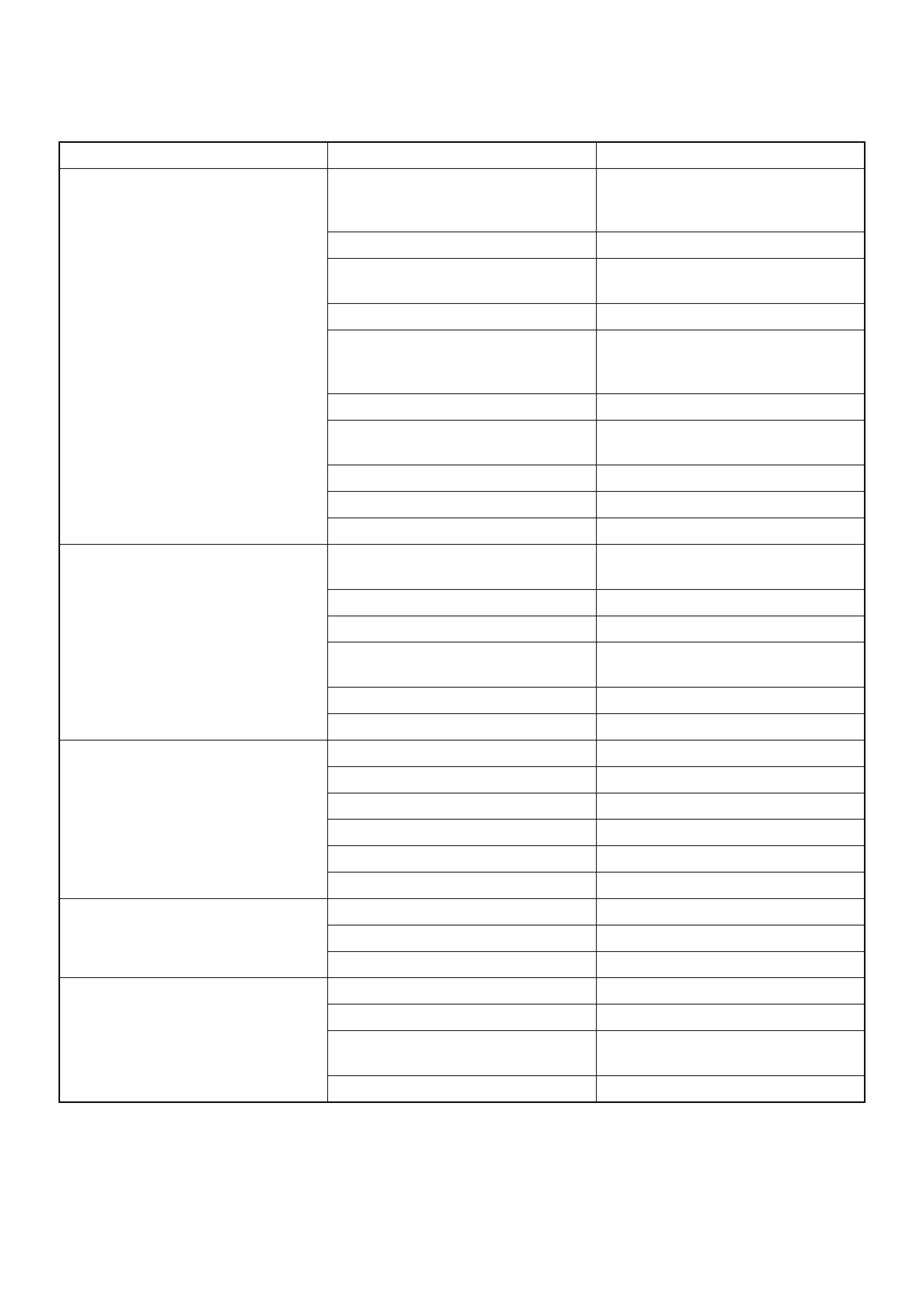
Condition Possible cause Correction
Body Leans Trim Height out of spec. Adjust Trim Height.
Loose stabiliser bar. Tighten stabiliser bar bolts or
replace bushings.
Faulty shock absorber, struts or
mounting.
Replace shock absorber.
Broken or sagging springs. Replace springs (In pairs).
Vehicle overloaded. Reduce load.
Cupped Tyres Worn hub unit bearings. Replace hub unit bearing.
Excessive tyre or wheel run out. Replace tyre or wheel.
Worn ball joints. Replace ball joints.
Tyre out of balance. Adjust tyre balance.
Condition Possible cause Correction
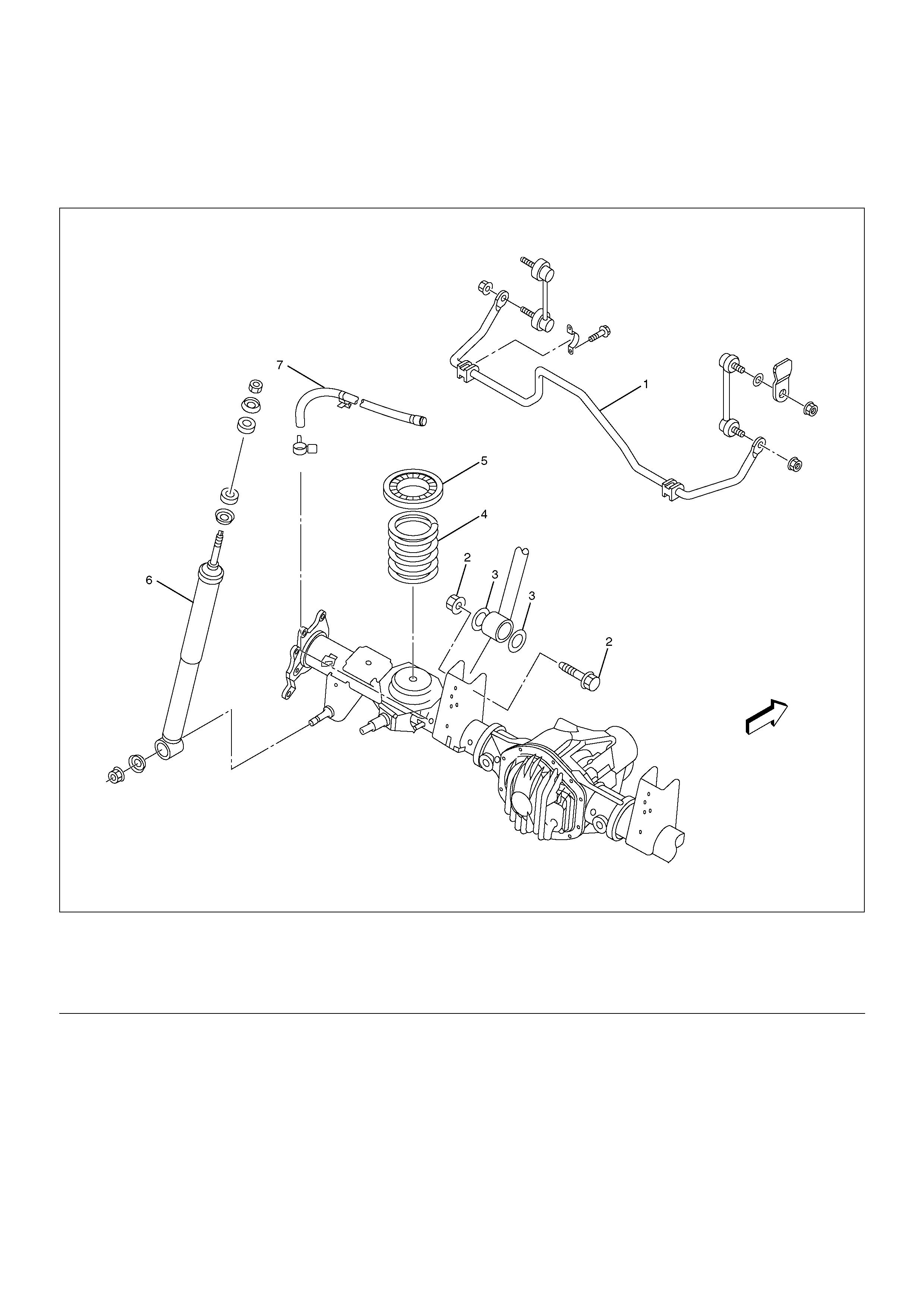
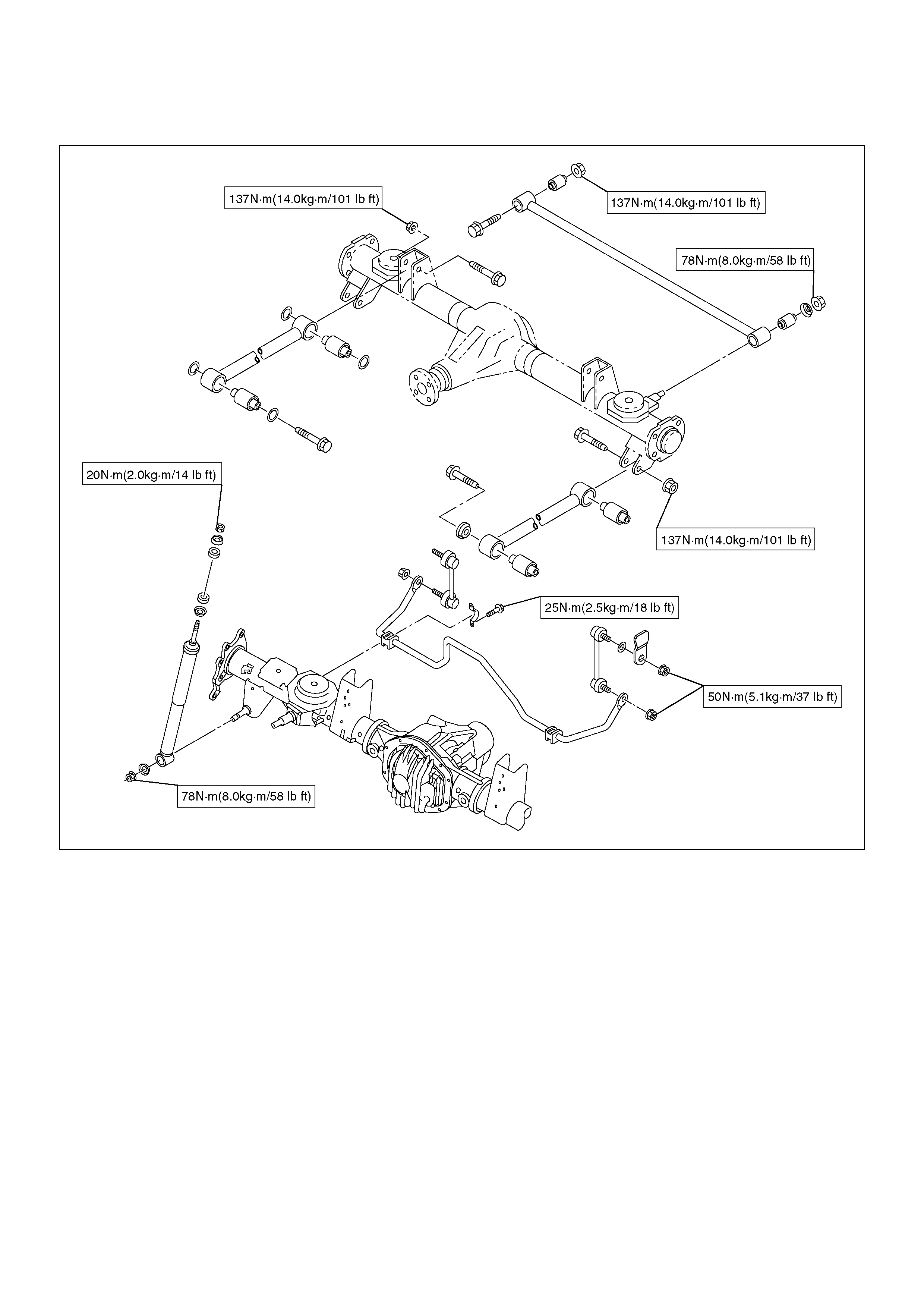
Coil Spring
Coil Spring and Associated Parts
460R200004
EndOFCallout
Removal
1.Raise the vehicle and support the frame with
suitable safety stands.
2.Support the rear axle case with a jack.
3.Disconnect brake hose at the crossmember.
4.Remove breather hose.
5.Remove upper link fixing bolt, nut and rubber plate
on the rear axle case (left-side only).
6.Disconnect the stabiliser bar at the stabiliser link.
7.Remove the shock absorber from the axle case.
8.Remove spring insulator.
9.Remove the insulator and coil spring while lowering
the rear axle case.
CAUTION: Be sure not to let the brake hose,
parking brake cable, and breather hose extend to
their full length.
Legend
(1) Stabiliser Bar
(2) Upper Link Fixing Bolt and Nut
(3) Rubber Plate
(4) Coil Spring
(5) Insulator
(6) Shock Absorbar
(7) Breather Hose
Inspection and Repair
Make necessary correction or parts replacement if wear,
damage, corrosion or any other abnormal condition are
found through inspection.
Check the following parts:
•Coil spring
•Insulator
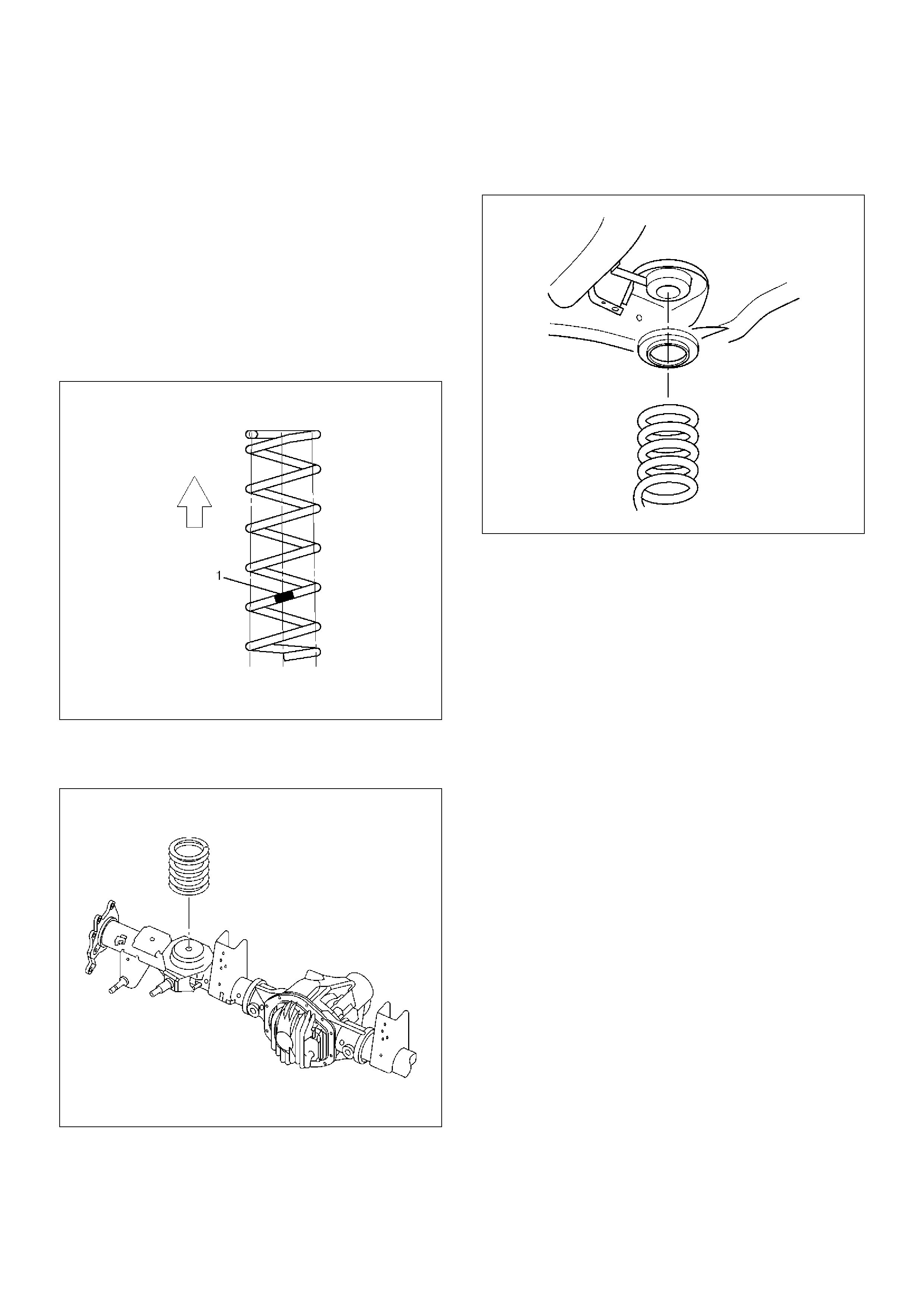
Installation
1.Install coil spring and make sure that the coil spring
is installed in the proper position. Paint mark(1)
should be downward.
460RW001
2.Fit the end of the coil spring to the coil spring seat
and mount the coil spring on the rear axle case.
460RW004
3.Install the insulator on the coil spring. Jack up the
axle case gently with the top of the coil spring set to
the spring seat on the frame side.
460RW013
4.Install shock absorber and tighten the nut lightly,
then retighten it to the specified torque after the
vehicle is at curb height.
NOTE: When mounting shock absorber, be sure not to
use grease on bushings or any other nearby part.
Torque: 78N·m (8.0kg·m/58lbft)
5.Install stabiliser bar at the stabiliser link.
Torque: 31N·m (3.2kg·m/23lbft)
6.Install upper link with rubber plate and tighten fixing
bolt.
Torque: 137N·m (14.0kg·m/101lbft)
7.Install breather hose.
8.Connect brake hose and bleed the brake system.
Refer to Bleeding the Brake Hydraulic System in
Brake section.
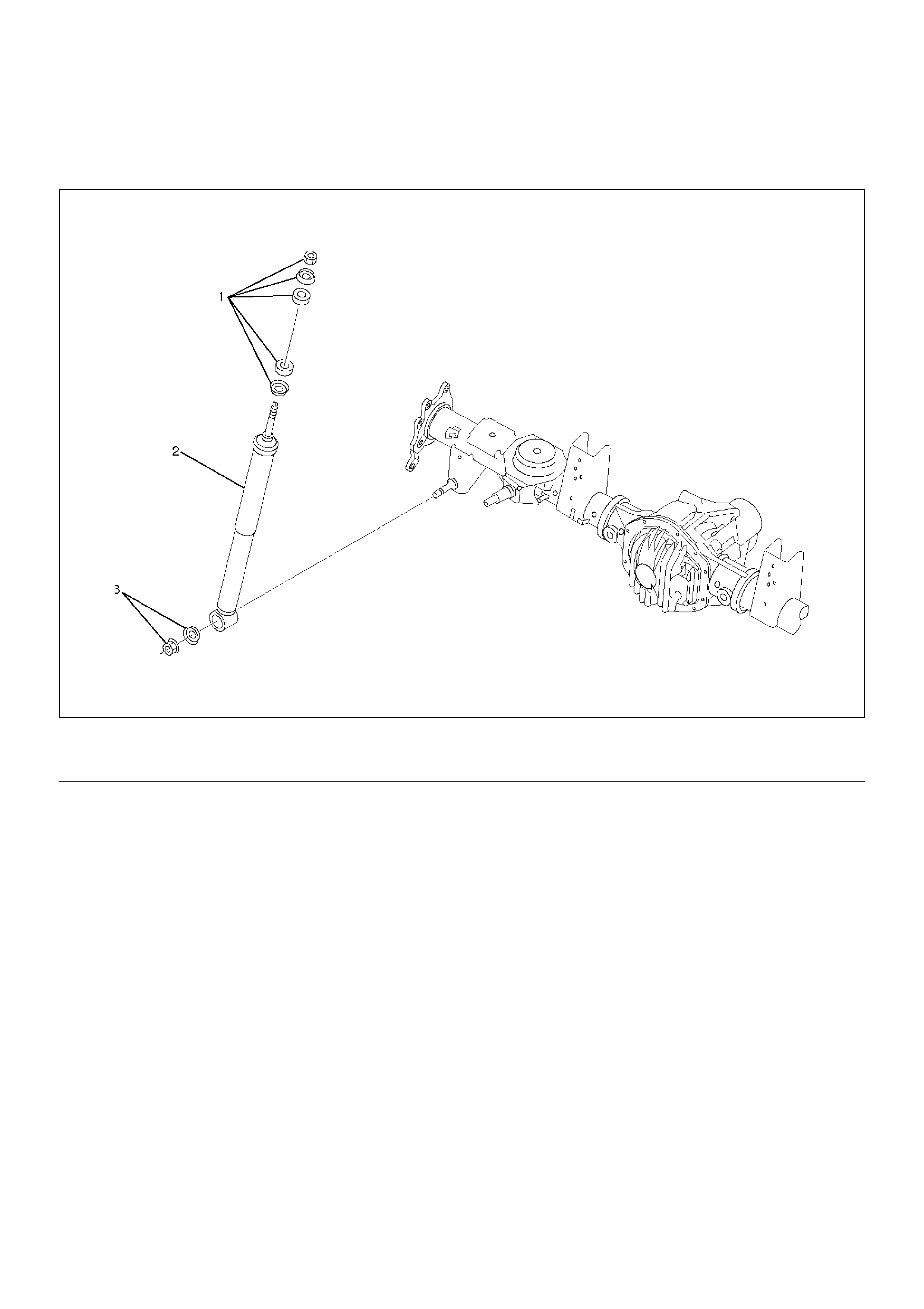
Shock Absorber
Shock Absorber and Associated Parts
461RW001
EndOFCallout
Removal
1. Remove shock absorber fixing nut, bush and
washer (upper side).
2. Remove shock absorber fixing nut and washer
(lower side).
3. Remove shock absorber.
Inspection and Repair
Make necessary correction or parts replacement if wear,
damage, corrosion or any other abnormal condition are
found through inspection.
Check the following parts:
• Shock absorber
• Rubber bushing
NOTE: When mounting rubber bushings, be sure not to
use grease on bushings or any other nearby part.
Installation
1. Install shock absorber. When mounting shock
absorber, be sure not to use grease on bushings or
any other nearby part.
2. Install nut and washer (lower side), then tighten the
nut lightly. Retighten to the bolt and nut specified
torque after the vehicle is at curb height.
Torque: 78N·m (8.0kg·m/58lbft)
3. Install nut, bush and washer (upper side), then
tighten the nut lightly. Retighten to the nut specified
torque after the vehicle is at curb height.
Torque: 20N·m (2.0kg·m/14lbft)
Legend
(1) Nut, Bush and Washer
(2) Shock Absorber
(3) Nut and Washer
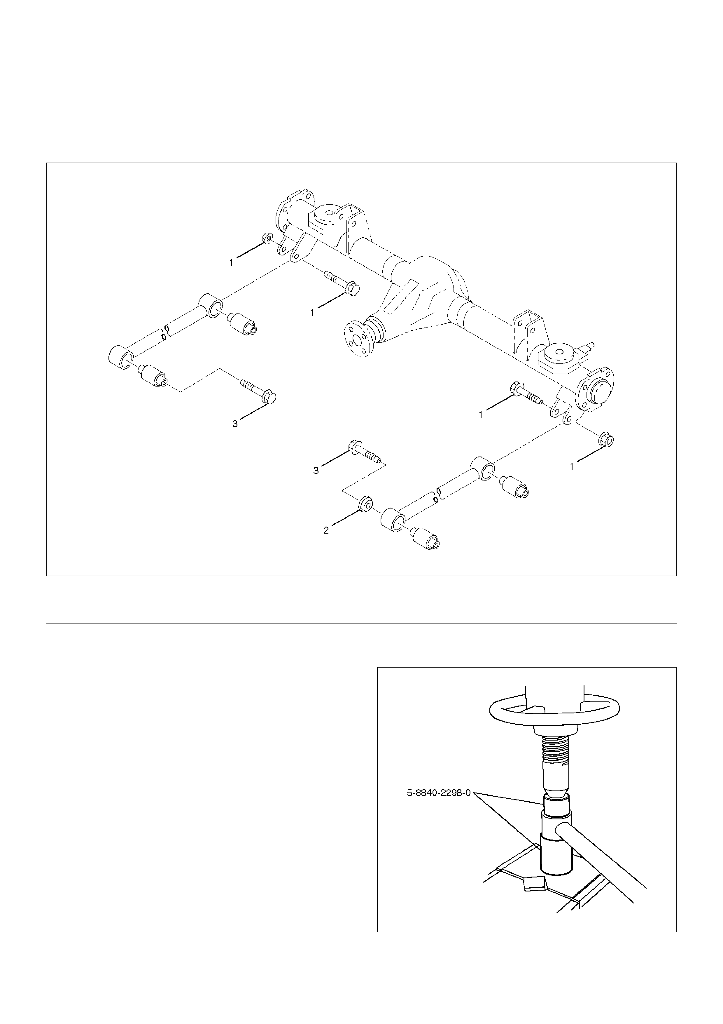
Trailing Link
Trailing Link and Associated Parts
460RW038
EndOFCallout
Removal
1. Remove the parking brake cable from the trailing
link.
2. Remove the trailing link fixing bolt, nut and
protector.
3. Remove trailing link.
Inspection and Repair
Make necessary correction or parts replacement if wear,
damage, corrosion or any other abnormal condition are
found through inspection.
1. Trailing link
2. Rubber bushing
• Remove the rubber bushing by using remover 5–
8840–2298–0.
901RW280
Legend
(1) Bolt and Nut (Axle side)
(2) Protector (Left side only)
(3) Bolt (Frame side)
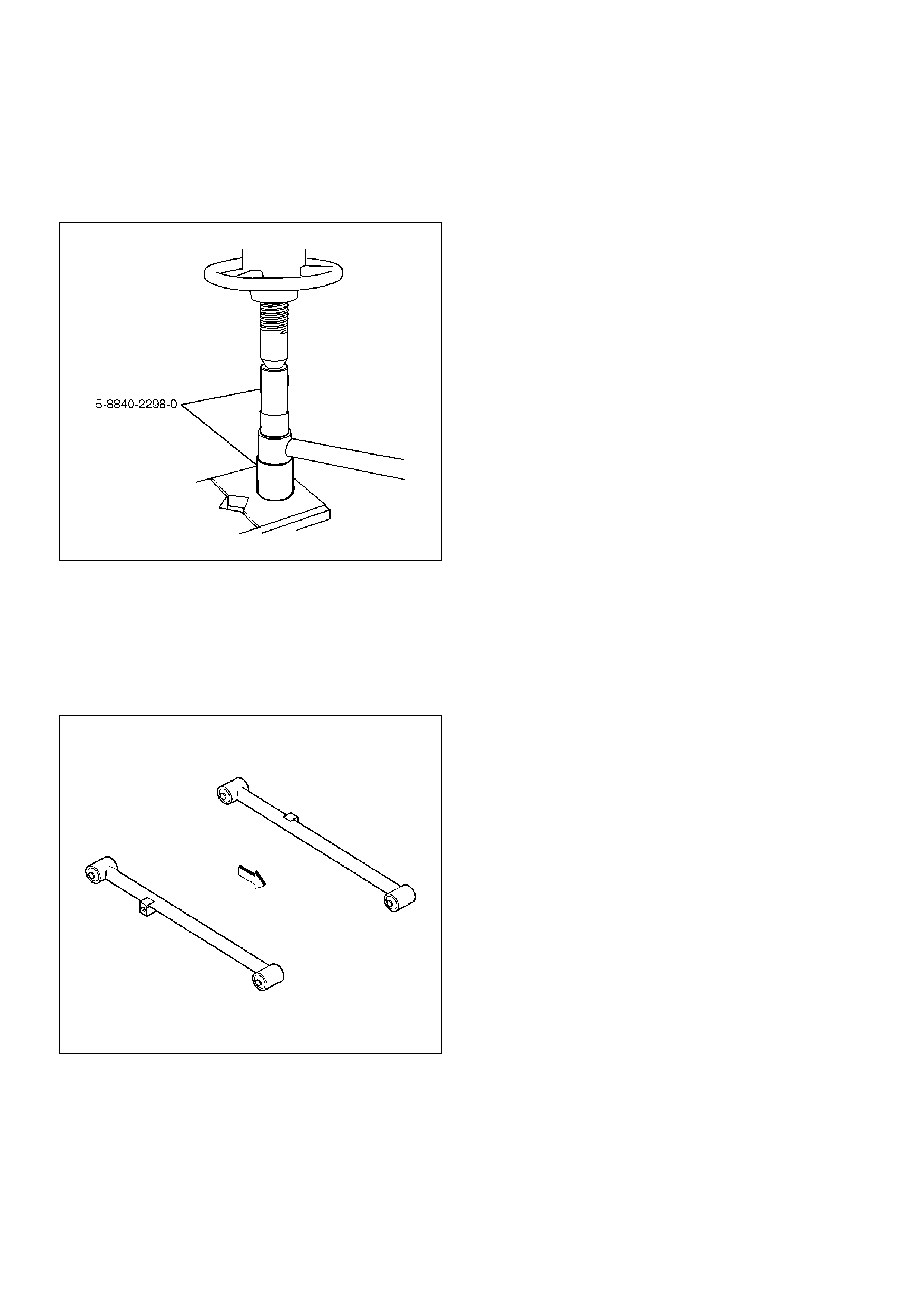
•Install the rubber bushing by using installer 5–
8840–2298–0.
NOTE: When mounting rubber bushings, be sure not to
use grease on bushings or any other nearby part.
901RW281
Installation
1.Install trailing link. Make sure that the trailing link is
in its correct position.
NOTE: When mounting trailing link, be sure not to use
grease on bushings or any other nearby part.
460RW011
2.Install bolt, nut and protector. Tighten the bolts and
nuts lightly, then retighten them to the specified
torque after the vehicle is at curb height.
Torque: 137N·m (14.0kg·m/101lbft)
3.Install parking brake cable.
CAUTION: The parking brake cable should not be
overstrained or slackened.
Upper Link
Upper Link and Associated Parts
460RW037-1
EndOFCallout
Removal
1.Remove fuel tank. Refer to Engine Fuel in Engine
section.
2. Remove the speed sensor cable from the upper link.
3. Remove bolt, nut, rubber plate and protector.
4. Remove upper link.
Inspection and Repair
Make necessary correction or parts replacement if wear,
damage, corrosion or any other abnormal condition are
found through inspection.
1. Upper link
2. Rubber bushing
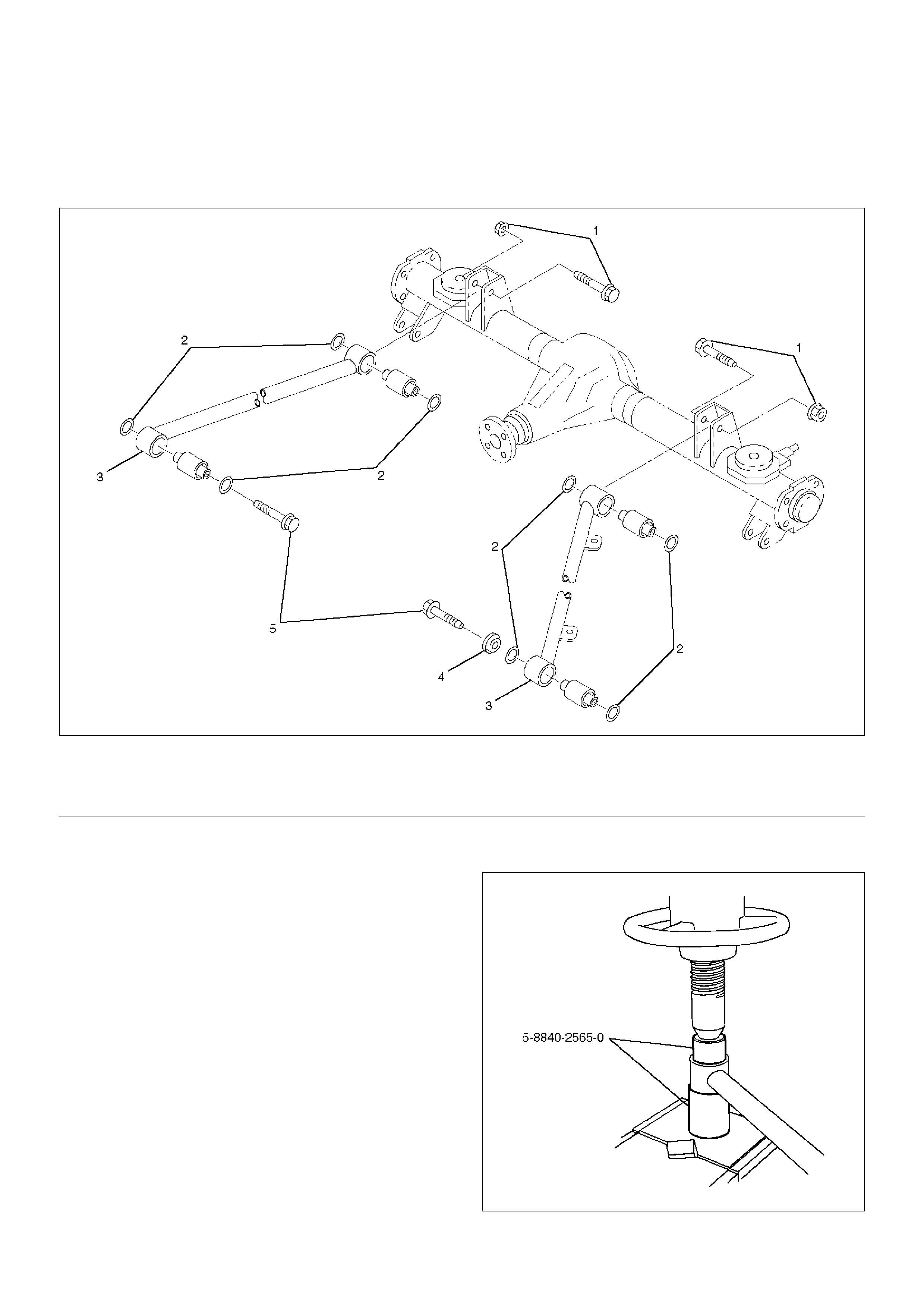
• Remove the rubber bushing by using remover 5–
8840–2565–0.
901RW282
Legend
(1) Bolt and Nut (Axle side)
(2) Rubber Plate
(3) Upper Link
(4) Protector (Left side only)
(5) Bolt (Frame side)
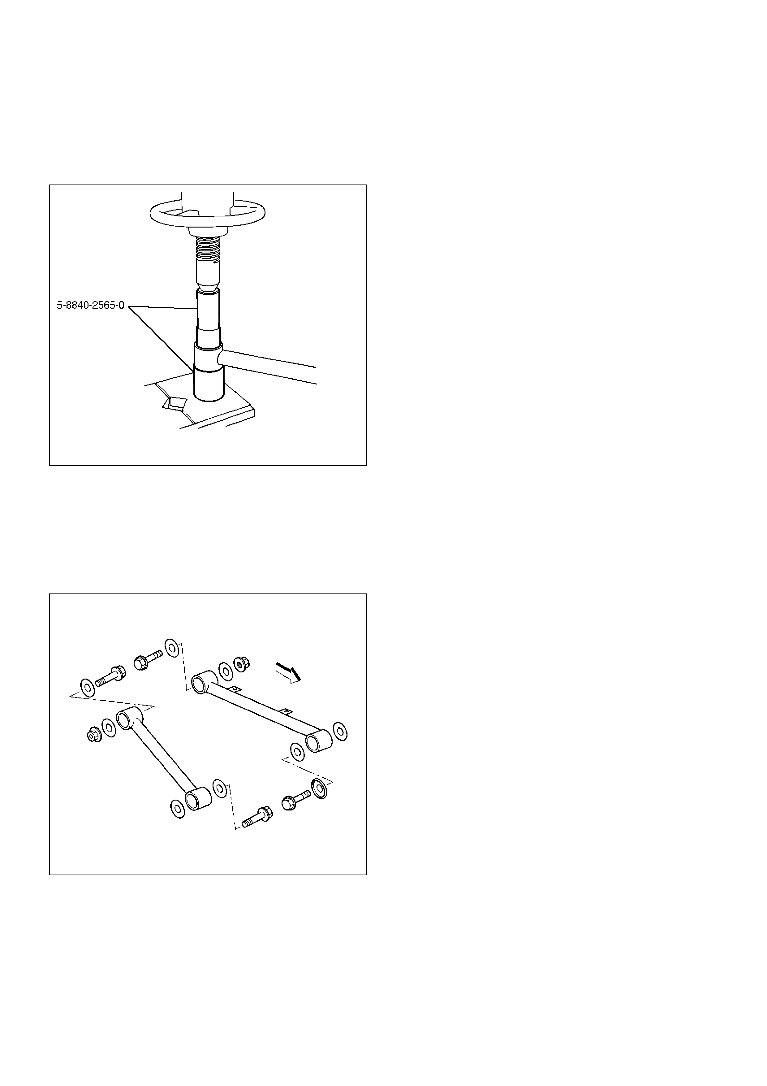
• Install the rubber bushing by using to installer 5–
8840–2565–0.
NOTE: When mounting rubber bushings, be sure not to
use grease on bushings or any other nearby part.
901RW283
Installation
1. Install upper link. Make sure that the upper link is in
its correct position.
NOTE: When mounting upper link, be sure not to use
grease bushings or any other nearby part.
460RW012
2. Install bolt, nut, rubber plate and protector. Tighten
the bolts and nuts lightly, then retighten them to the
specified torque after the vehicle is at curb height.
Torque: 137N·m (14.0kg·m/101lbft)
3. Install speed sensor cable.
4. Install fuel tank.
Lateral Rod
Lateral Rod and Associated Parts
460RW036
EndOFCallout
Removal
1. Remove nut and washer.
2. Remove bolt and nut.
3. Remove lateral rod.
Inspection and Repair
Make necessary correction or parts replacement if wear,
damage, corrosion or any other abnormal condition are
found through inspection.
1. Lateral rod
2. Rubber bushing (Frame side)
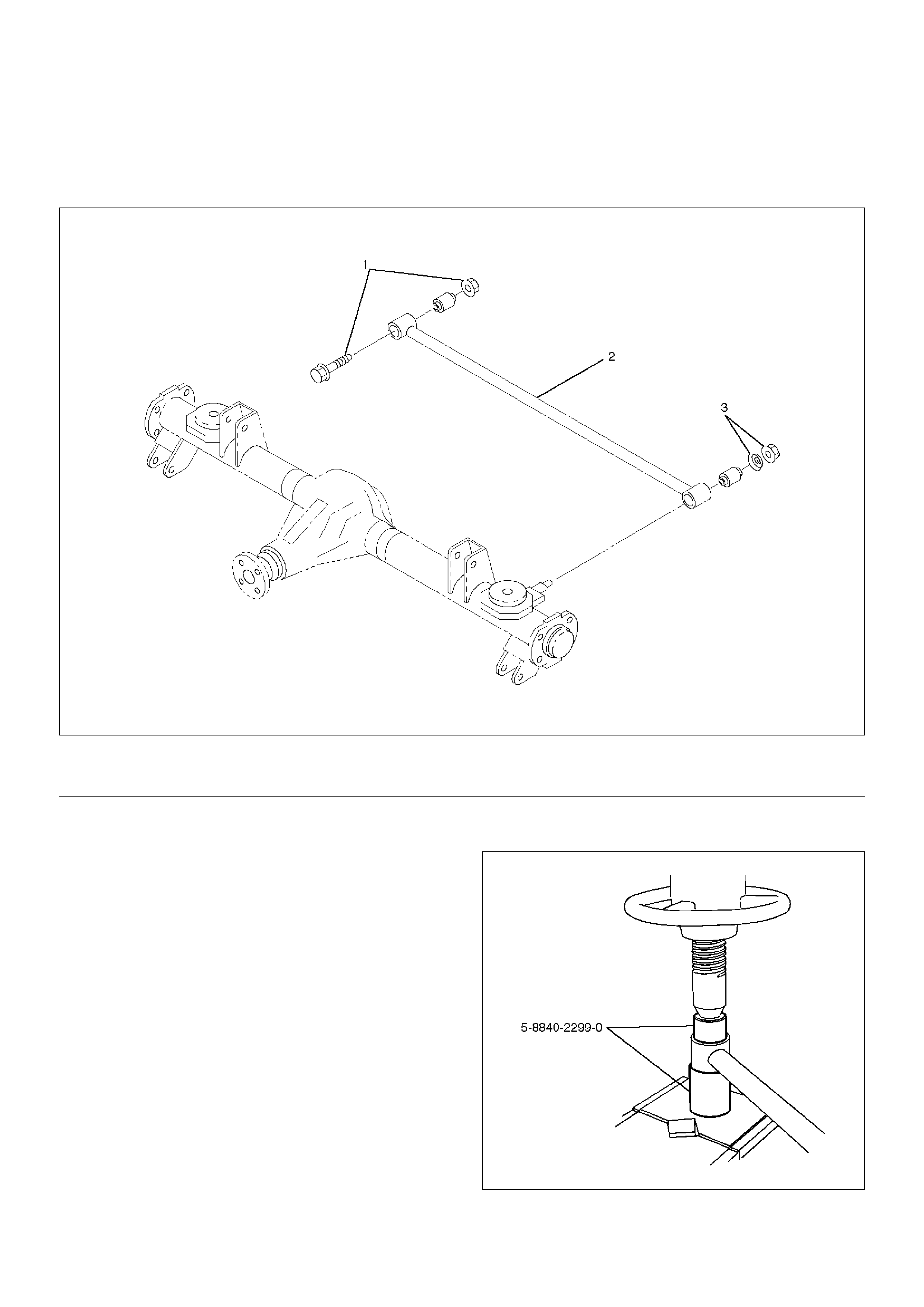
• Remove the rubber bushing (Frame side) by
using remover 5–8840–2299–0.
901RW284
Legend
(1) Bolt and Nut (Frame side)
(2) Lateral Rod
(3) Nut and Washer (Axle side)
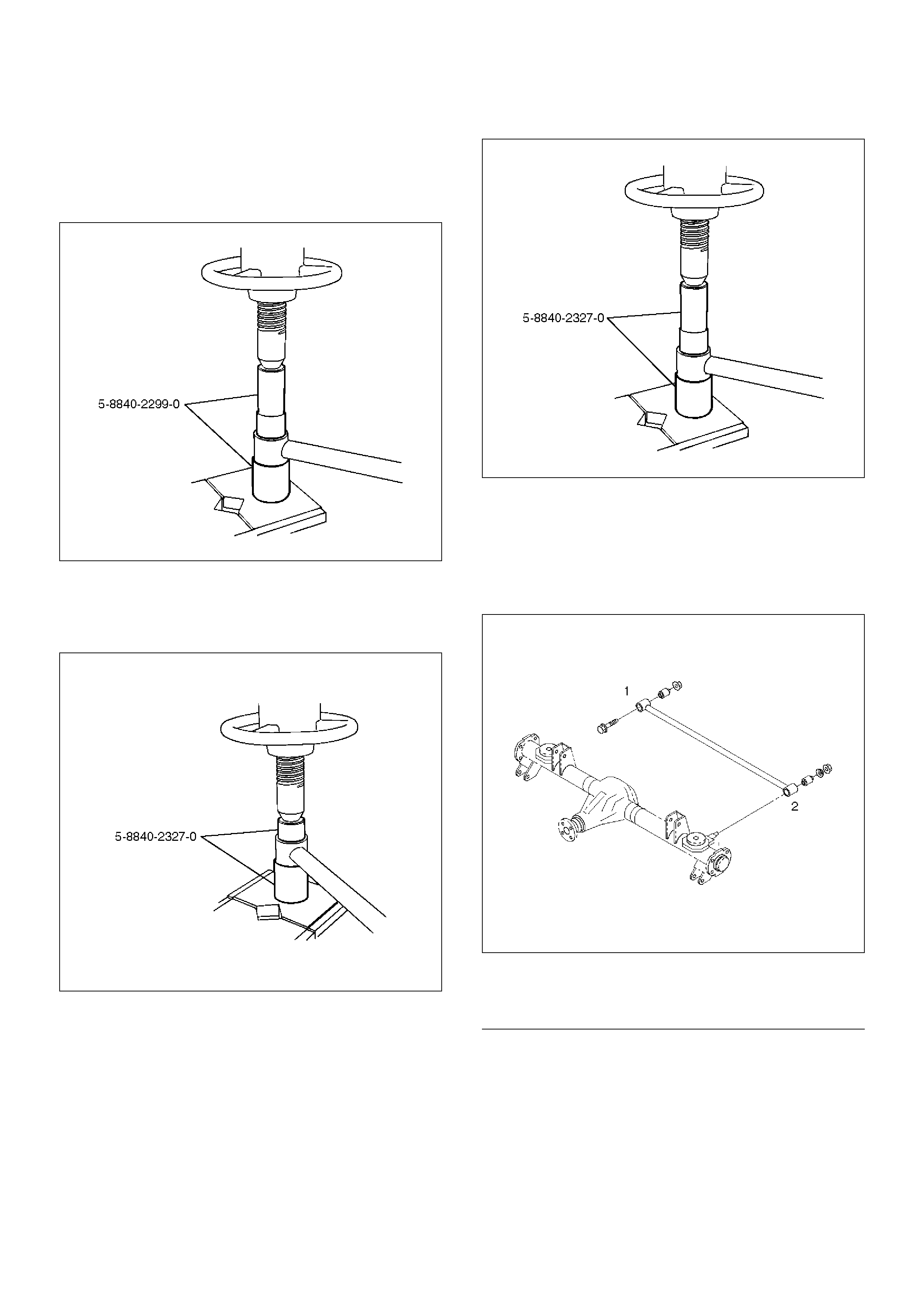
• Install the rubber bushing (Frame side) by using
Installer 5–8840–2299–0.
NOTE: When mounting rubber bushings, do not use
grease on bushings or any other nearby parts.
901RW285
3. Rubber bushing (Axle side)
• Remove the rubber bushing (Axle side) by using
remover 5–8840–2327–0.
901RW287
• Install the rubber bushing (Axle side) by using
installer 5–8840–2327–0.
901RW286
Installation
1. Install lateral rod and make sure that the lateral rod
is in its correct position.
NOTE: When mounting lateral rod, be sure not to use
grease on bushings or any other nearby part.
460RW035
EndOFCallout
2. Install bolt and nut (Frame side). Tighten the bolt
and nut lightly, then retighten them to the specified
torque after the vehicle is at curb height.
Torque: 137N·m (14.0kg·m/101lbft)
3. Install nut and washer (Axle side). Tighten the nut
lightly, then retighten the nut to the specified torque
after the vehicle is at curb height.
Torque: 78N·m (8.0kg·m/58lbft)
Legend
(1) Frame Side
(2) Axle Side
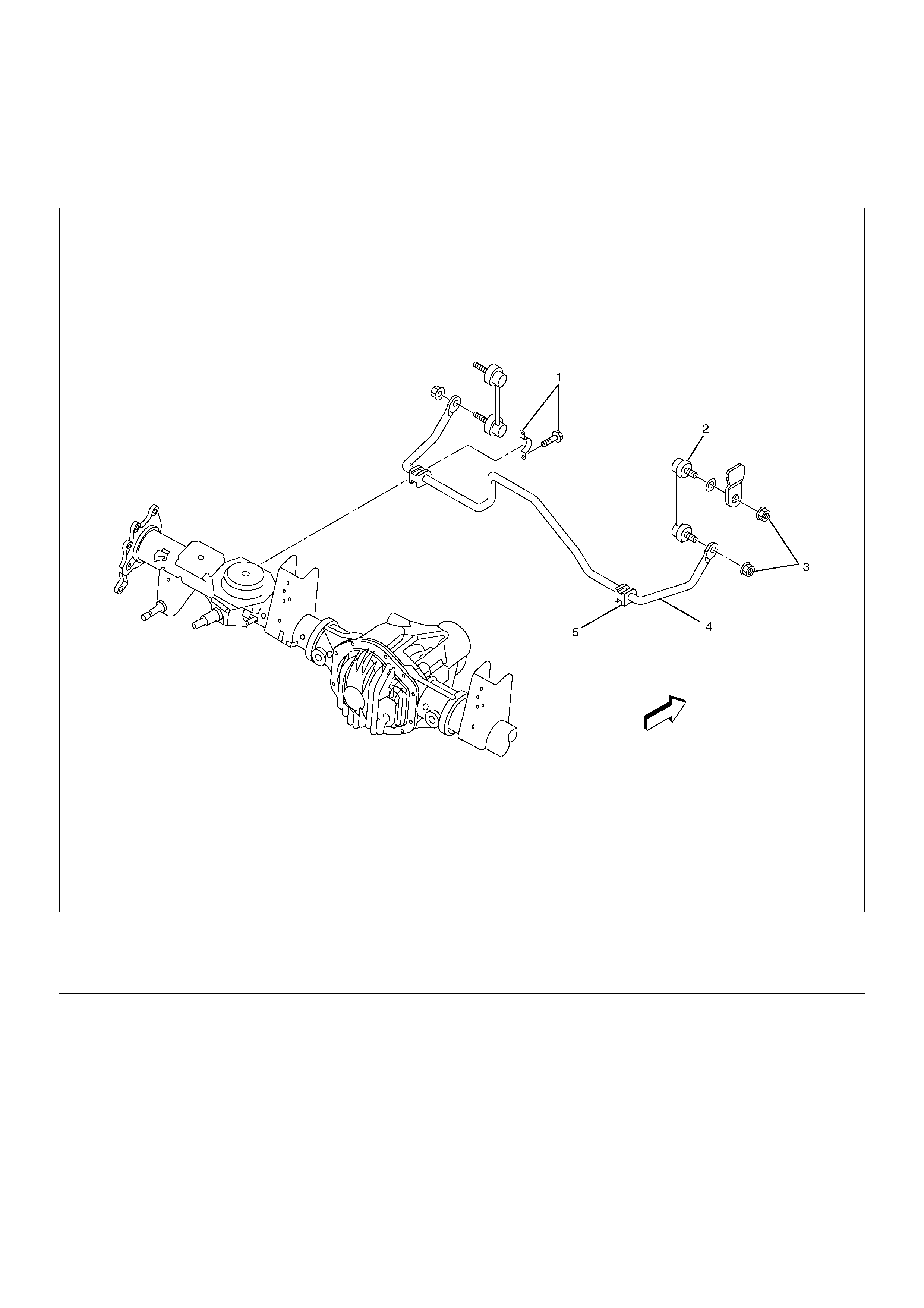
Stabiliser Bar
Stabiliser Bar and Associated Parts
460R200003
EndOFCallout
Removal
1.Raise the vehicle and support the frame with
suitable safety stands.
2.Remove wheel and tyre assembly. Refer to Wheel
in this section.
3. Remove nut.
4. Remove link.
5. Remove bracket.
6. Remove rubber bushing.
Inspection and Repair
Make necessary correction or parts replacement if wear,
damage, corrosion or any other abnormal condition are
found through inspection.
Check the following parts:
• Stabiliser bar
• Rubber bushing
•Link
Legend
(1) Bracket and Bolt
(2) Link
(3) Nut
(4) Stabiliser Bar
(5) Rubber Bushing
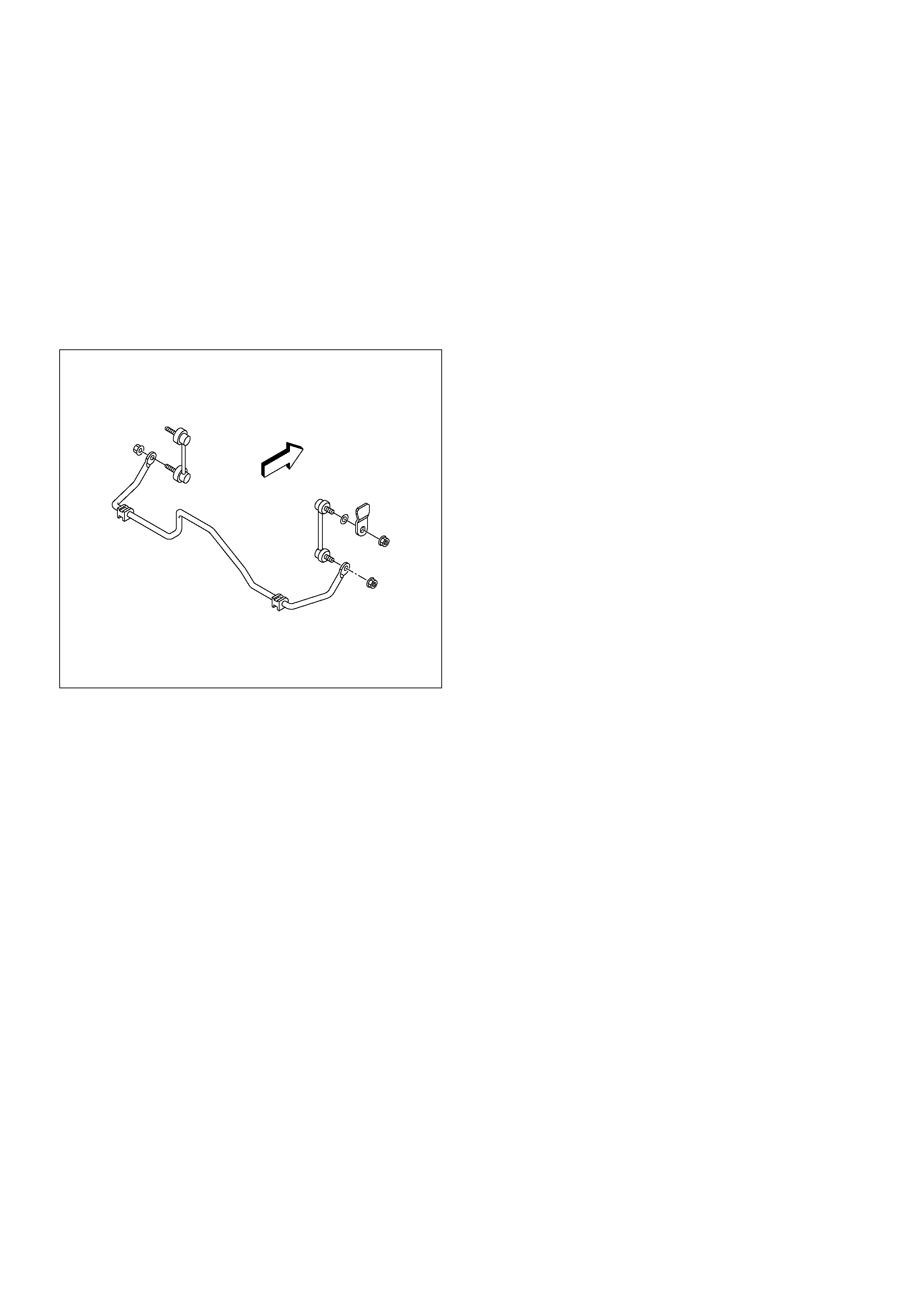
Installation
1. Install rubber bushing.
2. Install bracket to axle housing and tighten to the
specified torque.
Torque: 25N·m (2.5kg·m/18lbft)
3. Install link.
4. Install nut, then tighten the nut to the specified
torque.
Torque: 50N·m (5.1kg·m/37lbft)
460R200002
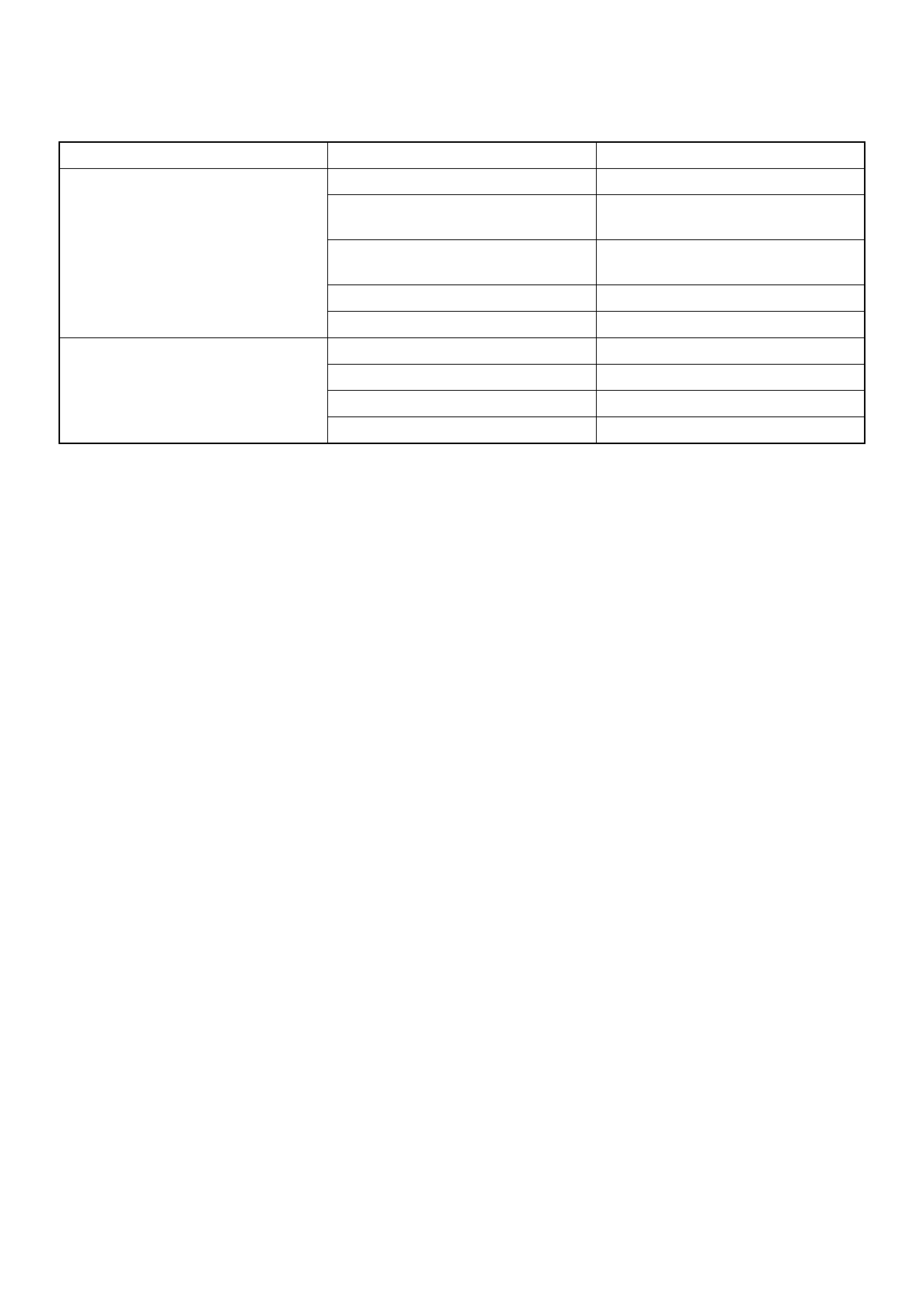
Main Data and Specifications
General Specifications
Rear suspension Type 5–Link, coil spring type with stabiliser bar.
Coil spring Free length 378.0mm (14.88in)
Spring diameter 12.8mm (0.5in)
Coil diameter (inner) 105mm (4.13in)
Effective No. of turns 6.00
Total No. of turns 7.50
Shock absorber Type Hydraulic, double acting, telescopic
Piston diameter 30mm (1.18in)
Stroke 175mm (6.89in)
Extended length 473.5mm (18.64in)
Compressed length 298.5mm (11.75in)
Stabiliser bar Diameter 19mm (0.75in)
Torque Specifications
E03R200010
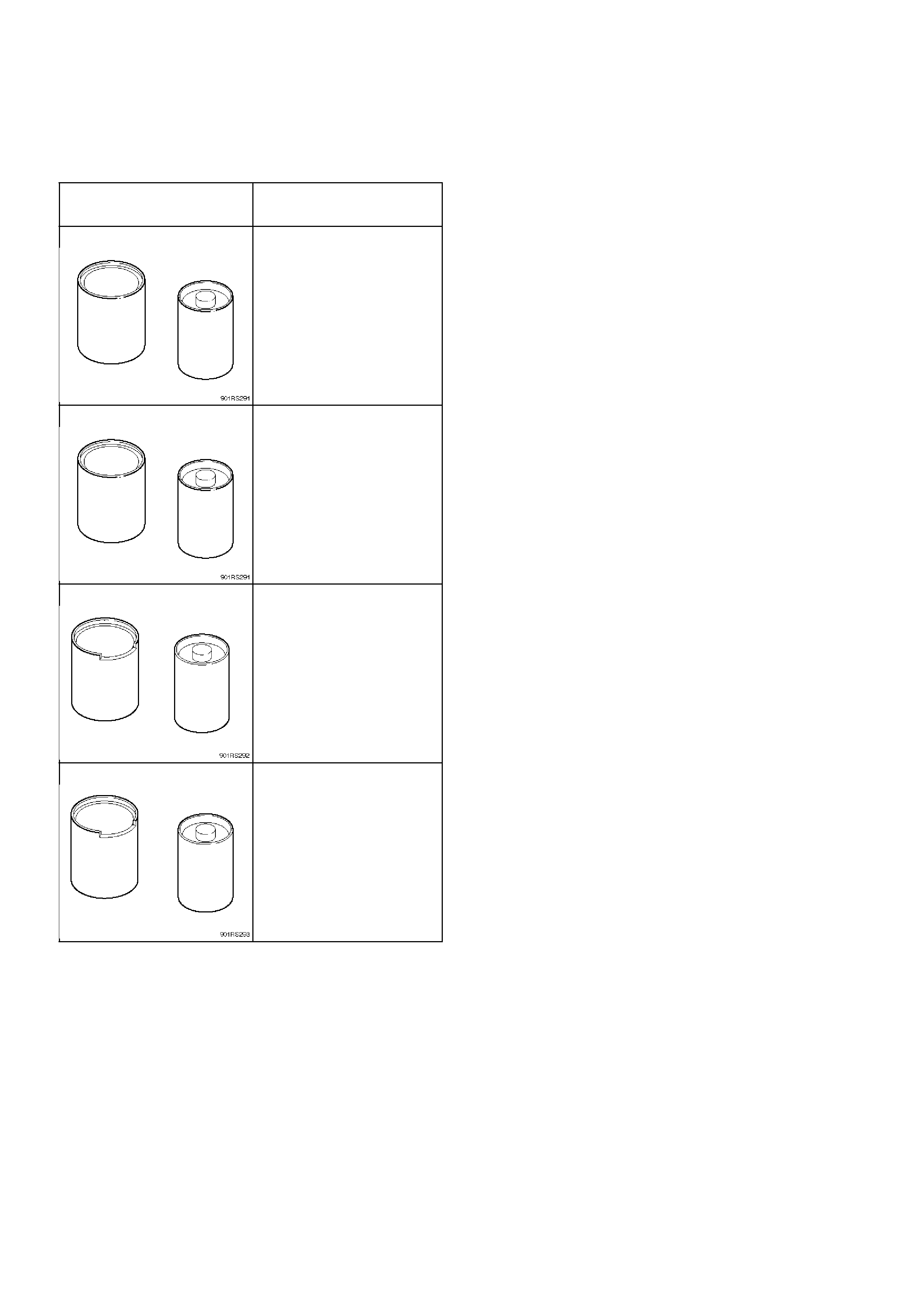
Special Tools
ILLUSTRATION TOOL NO.
TOOL NAME
5–8840–2298–0
(J–39214)
Remover and Installer;
Trailing link bushing
5–8840–2565–0
(J–43008)
Remover and Installer;
Upper link bushing
5–8840–2327–0
(J–39792)
Remover and Installer;
Lateral rod bushing (Axle
side)
5–8840–2299–0
(J–3921)
Remover and Installer;
Lateral rod bushing
(Frame side)