
SECTION 4D2 - DIFFERENTIAL (REAR) (MY2002)
Service Precaution
General Description
Diagnosis
Axle Housing
Axle Housing and Associated Parts
Removal
Installation
Axle Shaft, Oil Seal and Bearing
Axle Shaft and Associated Parts
Removal
Inspection
Installation
Pinion Oil Seal
Pinion Oil Seal and Associated Parts
Removal
Inspection and Repair
Installation
Differential Assembly
Disassembled View
Inspecting the Axle Before Disassembly
Disassembly
Inspection and Repair
Reassembly
Side Bearing Preload Adjustment
Pinion Installation
Determination of Backlash
& Preload Shims
Backlash Adjustment
Gear Tooth Pattern Check
Adjustments Affecting Tooth Contact
Differential Case Assembly
Disassembled View
Disassembly
Inspection and Repair
Reassembly
Limited Slip Differential Assembly
Disassembled View
Disassembly
Inspection and Repair
Reassembly
Main Data And Specifications
Special Tools
Service Precaution
WARNING: THIS VEHICLE HAS A SUPPLEMENTAL
RESTRAINT SYSTEM(SRS). REFER TO THE SRS
COMPONENT AND WIRING LOCATION VIEW IN
ORDER TO DETERMINE WHETHER YOU ARE
PERFORMING SERVICE ON OR NEAR THE SRS
COMPONENTS OR THE SRS WIRING. WHEN YOU
ARE REFORMING SERVICE ON OR NEAR THE SRS
COMPONENTS OR THE SRS WIRING, REFER TO
THE SRS SERVICE INFOMATION. FAILURE TO
FOLLOW WARNINGS COULD RESULT IN POSSIBLE
AIR BAG DEPLOYMENT, PERSONAL INJURY, OR
OTHERWISE UNNEEDED SRS SYSTEM REPAIRS.
CAUTION: Always use the correct fastener in the
proper location. When you replace a fastener, use
ONLY the exact part number for that application.
HOLDEN will call out those fasteners that require a
replacement after removal. HOLDEN will also call
out the fasteners that require thread lockers or
thread sealant. UNLESS OTHERWISE SPECIFIED ,
do not use supplemental coatings (Paints, greases,
or other corrosion inhibitors) on threaded fasteners
or fastener joint interfaces. Generally,such coatings
adversely affect the fastener torque and the joint
clamping force, and may damage the fastener.
When you install fasteners, use the correct
tightening sequence and specification. Following
these instructions can help you avoid damage to
parts and systems.
Techline
General Description
The rear axle assembly is of the semi–floating type in
which the vehicle weight is carried on the axle housing .
The center line of the pinion gear is below the center
line of the ring gear (hypoid drive).
All parts necessary to transmit power from the propeller
shaft to the rear wheels are enclosed in a salisbury type
axle housing (a carrier casting with tubes pressed and
welded into the carrier). A removable aluminum cover
at the rear of the axle housing permits rear axle service
without removal of the entyre assembly from the
vehicle.
The 8.9 inch ring gear rear axle uses a conventional
ring and pinion gear set to transmit the driving force of
the engine to the rear wheels. This gear set transfers
this driving force at a 90 degree angle from the propeller
shaft to the drive shafts.
The axle shafts are supported at the wheel end of the
shaft by a roller bearing.
The pinion gear is supported by two tapered roller
bearings. The pinion depth is set by a shim pack located
between the gear end of the pinion and the roller
bearing that is pressed onto the pinion. The pinion
bearing preload is set by crushing a collapsible spacer
between the bearings in the axle housing.
The ring gear is bolted onto the differential case with 10
bolts.
The differential case is supported in the axle housing by
two tapered roller bearings. The differential and ring
gear are located in relationship to the pinion by using
selective shims and spacers between the bearing and
the differential case. To move the ring gear, shims are
deleted from one side and an equal amount are added
to the other side. These shims are also used to preload
the bearings which are pressed onto the differential
case. Two bearing caps are used to hold the differential
into the rear axle housing.
The differential is used to allow the wheels to turn at
different rates of speed while the rear axle continues to
transmit the driving force. This prevents tyre scuffing
when going around corners and prevents premature
wear on internal axle parts.
The rear axle is sealed with a pinion seal, a seal at each
axle shaft end, and by a liquid gasket between the rear
cover and the axle housing.
Limited Slip Differential (LSD)
The axle assembly may be equipped with an limited slip
differential (LSD). It is similar to the standard differential
except that part of the torque from the ring gear is
transmitted through clutch packs between the side
gears and differential case.
The LSD construction permits differential action when
required for turning corners and transmits equal torque
to both wheels when driving straight ahead. However,
when one wheel tries to spin due to a patch of ice, etc.,
the clutch packs automatically provide more torque to
the wheel which is not trying to spin.
In diagnosing customer complaints, it is important to
recognize two things:
1. If, both wheels slip, with unequal traction, the LSD
has done all it can possibly do.
2. In extreame cases of differences in traction, the
wheel with the least traction may spin after the LSD
has transferred as much torque as possible to the
non-slipping wheel.
Limited Slip Differntials impose additional requirements
on lubricants, and require a special lubricant or lubricant
additive. Use 80W90 GL–5 LSD lubricant.
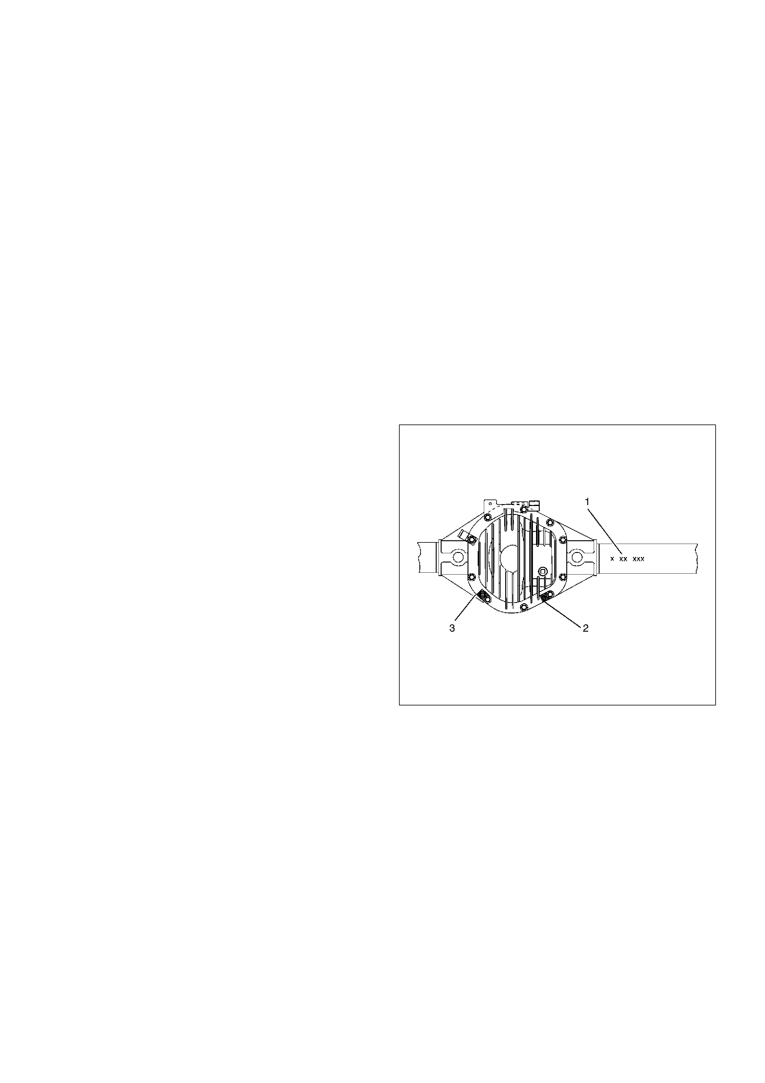
Rear Axle Identification
The Bill of Material and build date information(1) is
stamped on the right axle tube on the rearward side.
The axle ratio is identified by a tag(3) which is secured
by a cover bolt. If the axle has limited-slip differntial, it
also will be identified with a tag(2) secured by a cover
bolt.
425RX001

Diagnosis
Many noises that seem to come from the rear axle
actually originate from other sources such as tyres, road
surface, wheel bearings, engine, transmission, muffler,
or body drumming. Investigate to find the source of the
noise before disassembling the rear axle. Rear axles,
like any other mechanical device, are not absolutely
quiet but should be considered quiet unless some
abnormal noise is present.
To make a systematic check for axle noise, observe the
following:
1. Select a level asphalt road to reduce tyre noise and
body drumming.
2. Check rear axle lubricant level to assure correct
level, and then drive the vehicle far enough to
thoroughly warm up the rear axle lubricant.
3. Note the speed at which noise occurs. Stop the
vehicle and put the transmission in neutral. Run the
engine speed slowly up and down to determine if
the noise is caused by exhaust, muffler noise, or
other engine conditions.
4. Tyre noise changes with different road surfaces;
axle noises do not. Temporarily inflate all tyres to
344 kPa (50 psi) (for test purposes only). This will
change noise caused by tyres but will not affect
noise caused by the rear axle.
Rear axle nose usually stops when coasting at
speeds under 48 km/h (30 mph); however, tyre
noise continues with a lower tone. Rear axle noise
usually changes when comparing pull and coast, but
tyre noise stays about the same.
Distinguish between tyre noise and rear axle noise
by noting if the noise changes with various speeds
or sudden acceleration and deceleration. Exhaust
and axle noise vary under these conditions, while
tyre noise remains constant and is more
pronounced at speeds of 32 to 48 km/h (20 to 30
mph). Further check for tyre noise by driving the
vehicle over smooth pavements or dirt roads (not
gravel) with the tyres at normal pressure. If the
noise is caused by tyres, it will change noticeably
with changes in road surface.
5. Loose or rough front wheel bearings will cause
noise which may be confused with rear axle noise;
however, front wheel bearing noise does not change
when comparing drive and coast. Light application
of the brake while holding vehicle speed steady will
often cause wheel bearing noise to diminish. Front
wheel bearings may be checked for noise by jacking
up the wheels and spinning them or by shaking the
wheels to determine if bearings are loose.
6. Rear suspension rubber bushings and spring
insulators dampen out rear axle noise when
correctly installed. Check to see that there is no link
or rod loosened or metal–to–metal contact.
7. Make sure that there is no metal–to–metal contact
between the floor and the frame.
After the noise has been determined to be in the axle,
the type of axle noise should be determined, in order to
make any necessary repairs.
Gear Noise
Gear noise (whine) is audible from 32 to 89 km/h (20 to
55 mph) under four driving conditions.
1. In drive under acceleration or heavy pull.
2. Driving under load or under constant speed.
3. When using enough throttle to keep the vehicle from
driving the engine while the vehicle slows down
gradually (engine still pulls slightly).
4. When coasting with the vehicle in gear and the
throttle closed. The gear noise is usually more
noticeable between 48 and 64 km/h (30 and 40
mph) and 80 and 89 km/h (50 and 55 mph).
Bearing Noise
Bad bearings generally produce a rough growl or
grating sound, rather than the whine typical of gear
noise. Bearing noise frequently “wow–wows" at bearing
rpm, indicating a bad pinion or rear axle side bearing.
This noise can be confused with rear wheel bearing
noise.
Rear Wheel Bearing Noise
Rear wheel bearing noise continues to be heard while
coasting at low speed with transmission in the neutral.
Noise may diminish by gentle braking. Jack up the rear
wheels, spin them by hand and listen for noise at the
hubs. Replace any faulty wheel bearings.
Knock At Low Speeds
Low speed knock can be caused by worn universal
joints or a side gear hub counter bore in the cage that is
worn oversize. Inspect and replace universal joints or
cage and side gears as required.
Backlash Clunk
Excessive clunk on acceleration and deceleration can
be caused by a worn rear axle pinion shaft, a worn
cage, excessive clearance between the axle and the
side gear splines, excessive clearance between the
side gear hub and the counterbore in the cage, worn
pinion and side gear teeth, worn thrust washers, or
excessive drive pinion and ring gear backlash. Remove
worn parts and replace as required. Select close–fitting
parts when possible. Adjust pinion and ring gear
backlash.
Rear Axle Noise
Limited Slip Differential
Condition Possible cause Correction
Noise in Drive Excessive pinion to ring gear
backlash.
Adjust.
Worn pinion and ring gear. Replace
Worn pinion .bearings. Replace.
Loose pinion bearings. Adjust.
Excessive pinion end play. Adjust.
Worn side bearings. Replace.
Loose side bearings. Adjust.
Excessive ring gear run-out. Replace.
Low oil level. Replenish.
Wrong or poor grade oil. Replace.
Bent axle housing. Replace.
Noisy when coasting Axle noise heard when driving will
usually be heard also on coasting,
although not as loud.
Adjust or replace.
Pinion and ring gear too tight
(audible when slowing down and
disappears when driving).
Adjust.
Intermittent noise Warped bevel ring. Replace.
Loose differential case bolts. Tighten.
Constant noise Flat spot on pinion or ring gear
teeth.
Replace.
Flat spot on bearing. Replace.
Worn pinion splines. Replace.
Worn axle shaft dowel holes. Replace.
Worn hub studs. Replace.
Bent axle shaft. Replace.
Noisy on turns Worn differential side gears and
pinions.
Replace.
Worn differential shaft. Replace.
Worn axle shaft splines. Replace.
Condition Possible cause Correction
Does not lock Broken clutch plates. Replace the clutch plates.
Chatters in turns Lubricant contaminated. Drain lube when hot. Wipe carrier
clean. Refill with lube specified in
Main Data and Specifications at the
end of this section.
Clutch plates dateriorated. Replace clutch plates.
Noise (in addition to normal clutch
engagement)
Broken clutch plates. Replace clutch plates.
Damaged case. Replace unit.
Broken differential gears. Replace gears.
Axle Housing
Axle Housing and Associated Parts
420RW030
Legend
EndOFCallout
Removal
1.Raise the vehicle and support it with suitable safety
stands.
The hoist must remain under the rear axle housing.
2.Take out brake fluid. Refer to Hydraulic Brakes in
Brake section.
3.Remove rear wheels and tyres. Refer to Wheel
Replacement in Section 10.
4.Remove propeller shaft. Refer to Rear Propeller
Shaft in this section.
5. Drain the rear axle oil into a proper container.
6. Remove parking brake cable, release the
connection between the cable fixing clip equalizer.
Refer to Parking Brakes in Brake section.
7. Move the clip aside and pull out the breather hose.
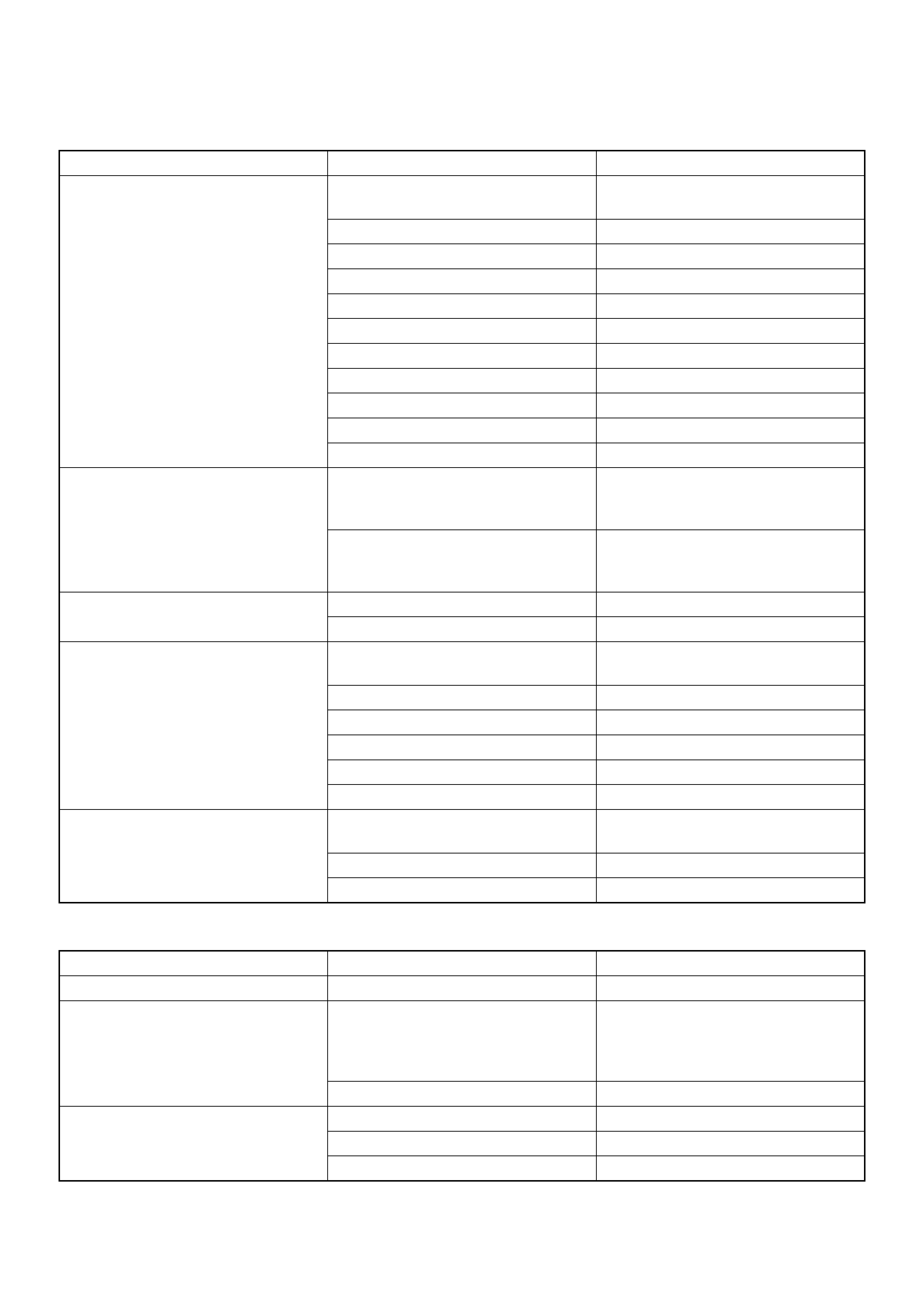
8. Disconnect the ABS connectors (1) and remove the
brackets attached to the frame and center link.
350R200005
(1) Lower Link
(2) Stabilizer
(3) Upper Link
(4) Rear Propeller shaft
(5) Shock Absorber
(6) Lateral Rod
(7) Brake Hose
(8) Coil Spring
(9) Parking Cable
(10) Axle Assembly
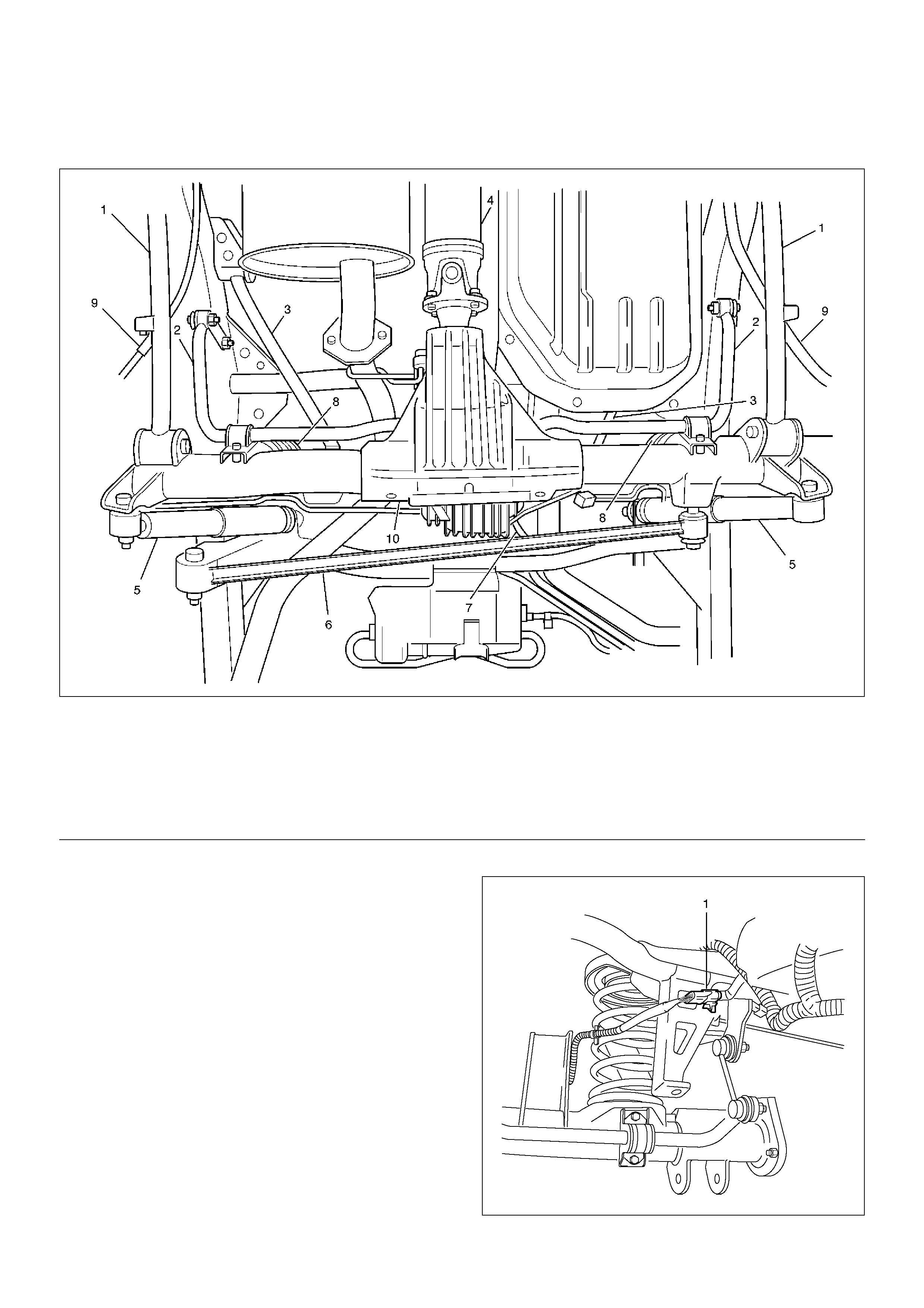
9. Loosen the brake tube flare nut, remove the clip and
take out the brake tube.
350RW020
10. Remove the shock absorber.
11. Remove the stabilizer linkage mounting nuts (2)
from the frame side.
350R200006
12. Remove the lateral rod fixing bolt and nut from the
frame.
13. Remove the upper link mounting bolt and nut (3)
from the axle housing.
460RW015
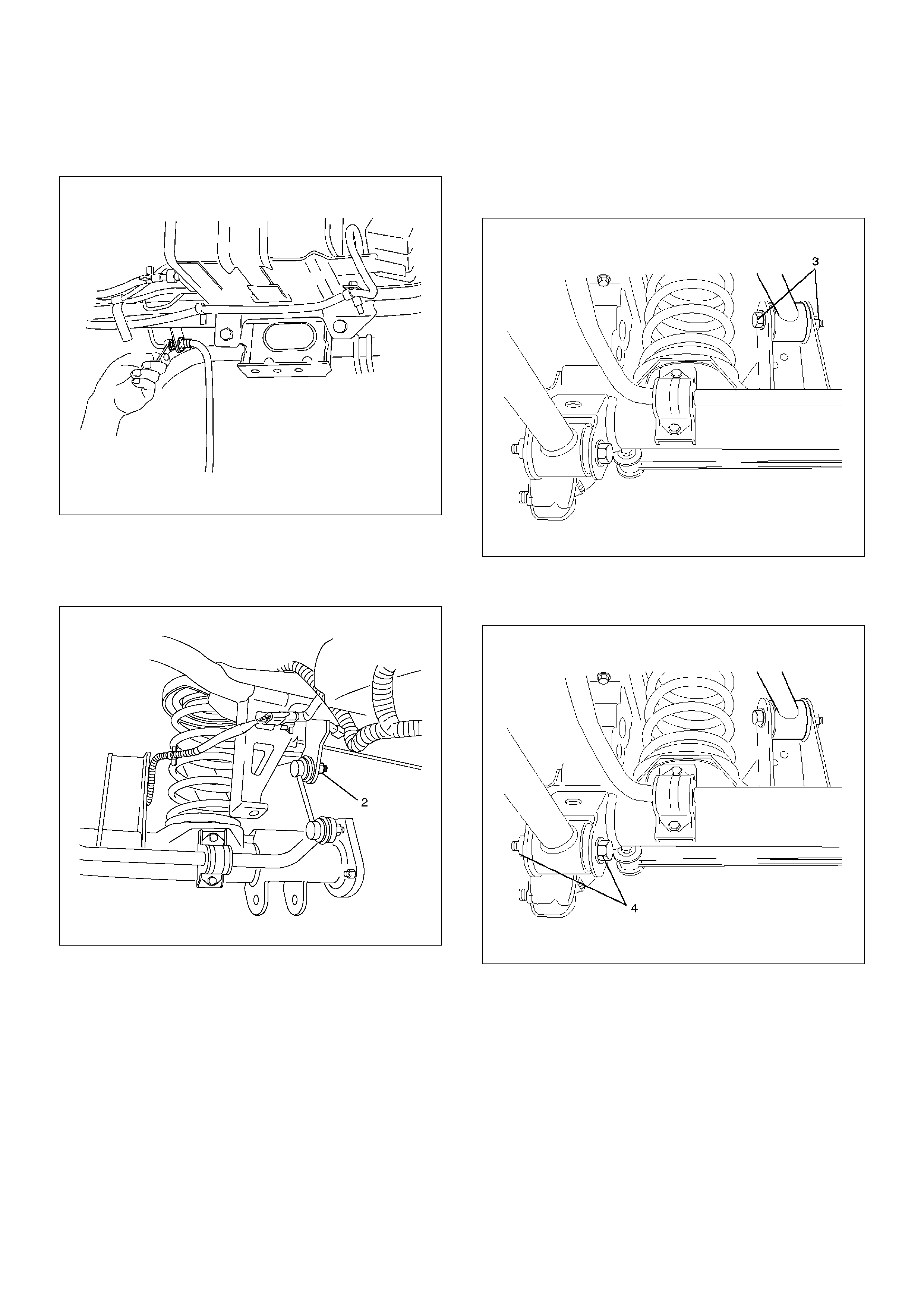
14. Remove the lower link fixing bolt and nut (4) from
the axle housing.
460RW016
15. Jack down and remove the coil spring and insulator.
16. Axle housing assembly can be separated from the
vehicle on completion of steps 1 – 15.
17. Remove the brake caliper fixing bolt, loosen the
flare nut, release the clip and take out the brake
caliper together with the flexible hose.
18. Remove brake disc.
19. Remove antilock brake system speed sensor fixing
bolt and the clip and bracket on the axle housing.
20. Remove the brake pipe clip and fixing bolt on the
axle housing and take out the brake pipe.
Installation
1.Install brake pipe.
2.Connect Antilock brake system (ABS) speed sensor
and harness, refer to Anti–Lock Brake System in
Brake section.
3.Install brake disc.
4.Install brake caliper. Refer to Disc Brakes in Brake
section.
5.Install axle housing assembly.
6.Install coil spring and insulator.
7.Install the lower link fixing bolt and nut to the axle
housing. For the procedures in items 7–11, refer to
Suspension section.
8.Install the upper link bolt and nut to the axle
housing.
9.Install the lateral rod fixing nut and bolt to the frame
side.
10.Install the stabilizer linkage mounting nuts to the
frame side.
11.Install the shock absorber.
12.Install brake tube flare nut, Refer to Disc Brakes in
Brake section.
13. Install ABS connector and bracket.
14. Connect breather hose.
15.Install parking brake cable, Refer to Parking Brakes
in Brake section.
16.Bleed brakes. Refer to Hydraulic Brakes in Brake
section.
Axle Shaft, Oil Seal and Bearing
Axle Shaft and Associated Parts
420RW008
Legend
EndOFCallout
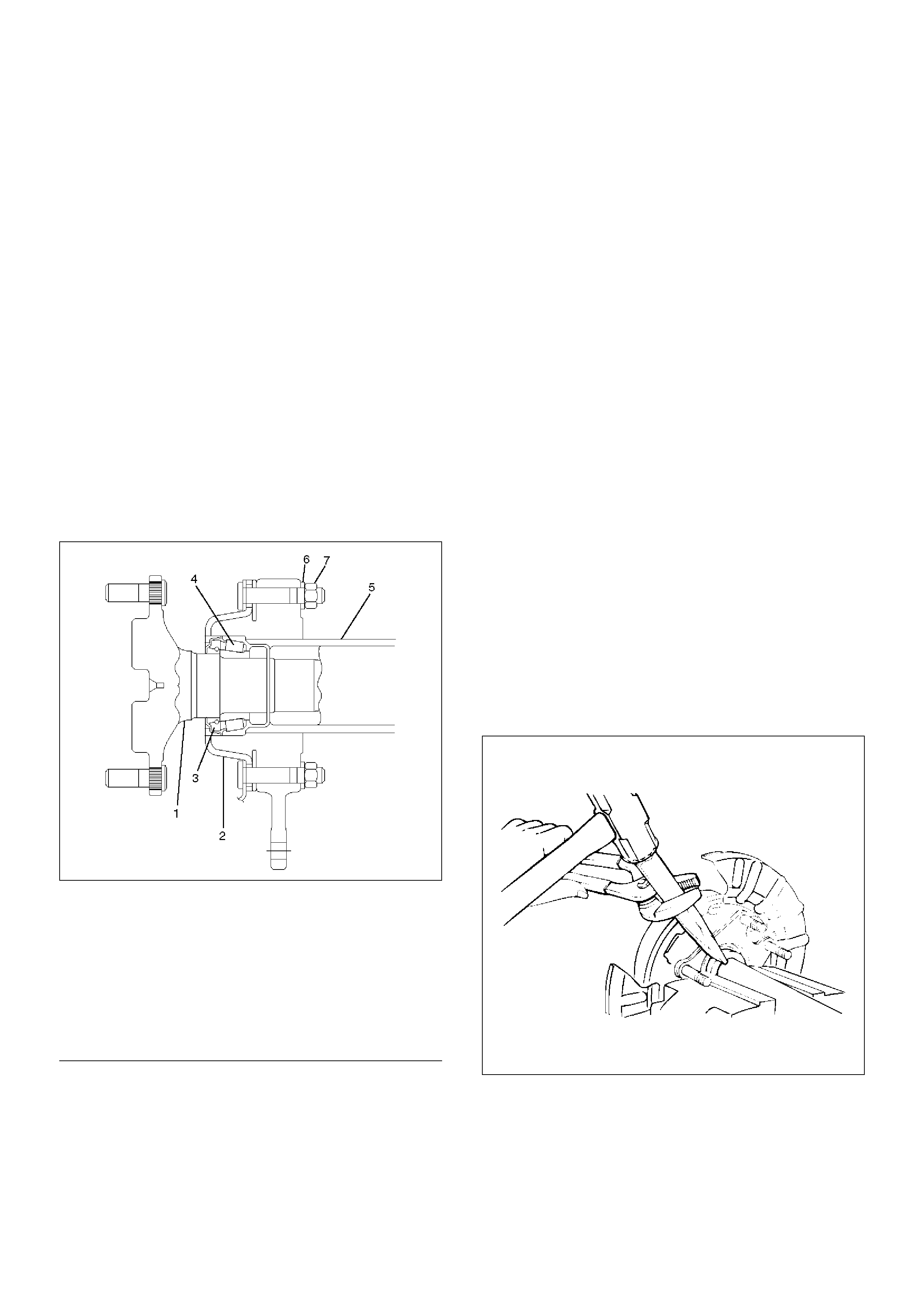
Removal
1. Raise the vehicle.
2. Remove rear wheels and brake calipers or drums.
Do not let calipers hang from the vehicle by the
brake line or hose. Wire them to frame of vehicle to
prevent damage.
3. Remove four nuts and lockwashers.
4. Remove shaft assembly from the axle housing.
5. Remove snap ring and bearing cup.
6. Break retainer ring with hammer and chisel.
420RS026
(1) Axle Shaft
(2) Backing Plate
(3) Oil Seal
(4) Bearing
(5) Axle Housing
(6) Lock Washer
(7) Nut
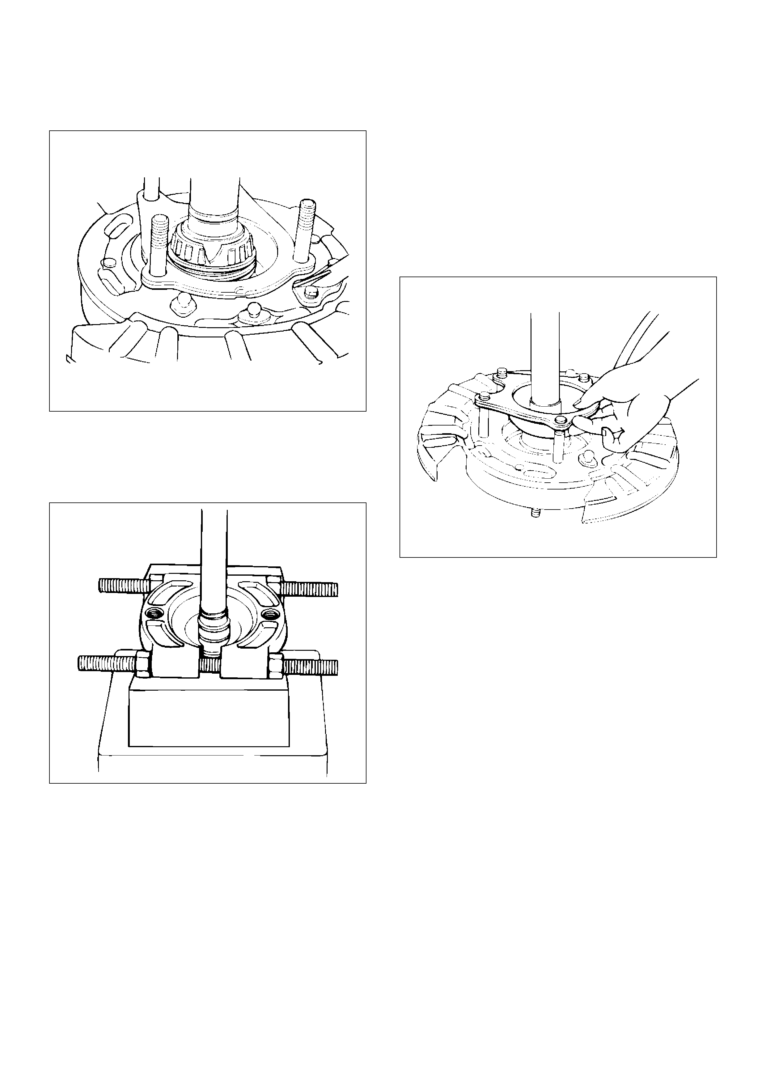
7. Break bearing cage with hammer and chisel.
420RS027
8. Remove oil seal, retainer, and emergency brake
assembly.
9. Remove inner race from shaft with OTC–1126
bearing splitter and press.
420RS028
Inspection
• Shaft for spalling or grooves from seal wear.
• Retainer – bent or damaged.
• Replace items if required.
Installation
1. Emergency brake assembly.
2. Install retainer.
Note direction – do not install backwards.
420RS029
3. Install oil seal. Note direction.
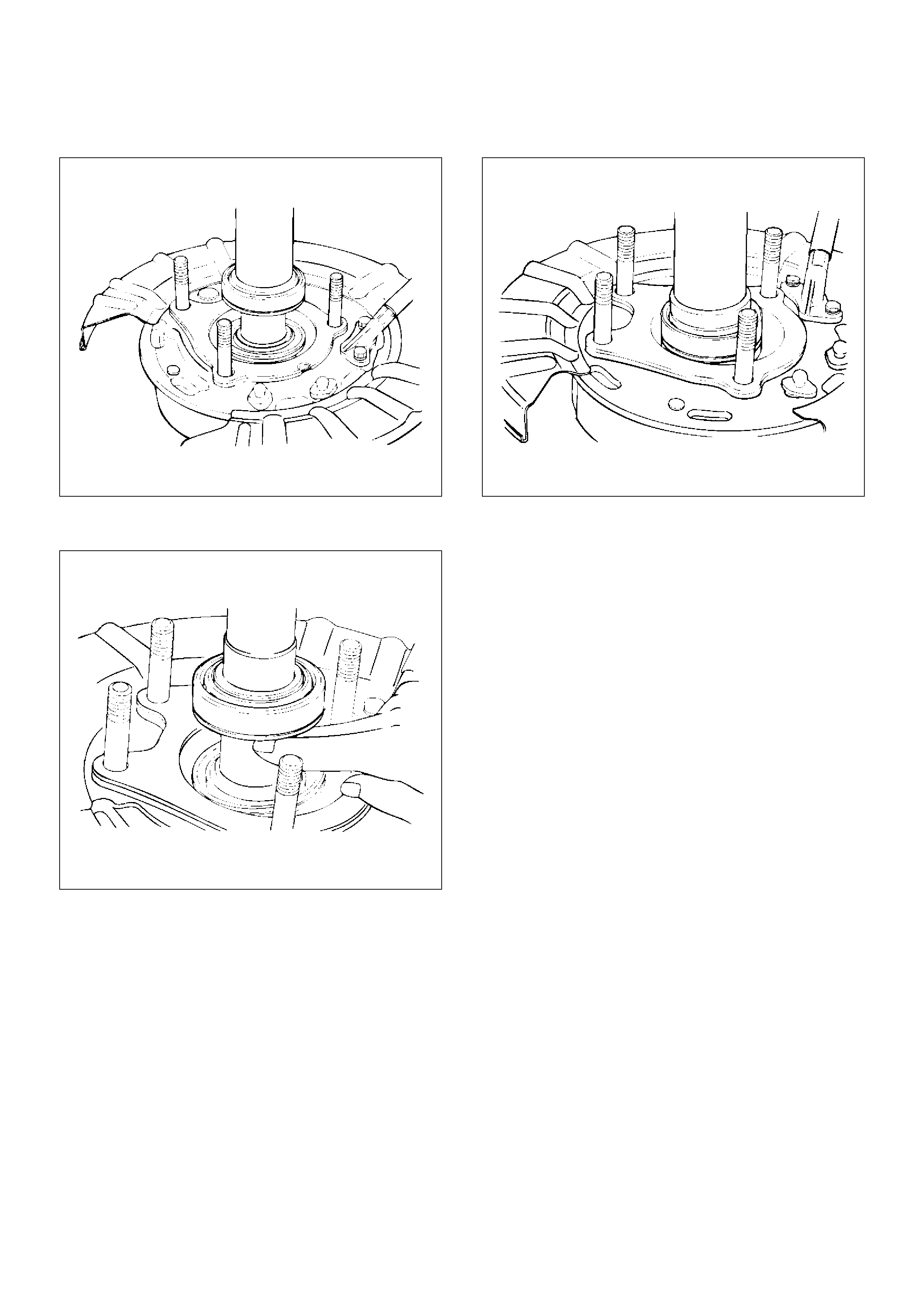
4. Install bearing assembly, using installer and press.
420RS030
NOTE: Install bearing with cup towards inboard side.
420RS031
5. Install retainer ring, using installer and press.
420RS033
6. Install snap ring.
7. Install axle shaft assembly into housing.
8. Install bolts, lockwashers, and nuts.
Tighten the retainer nuts to the specified torque.
Torque : 75N·m (7.6kg·m/55lbft)
Pinion Oil Seal
Pinion Oil Seal and Associated Parts
420RW013
Legend
EndOFCallout
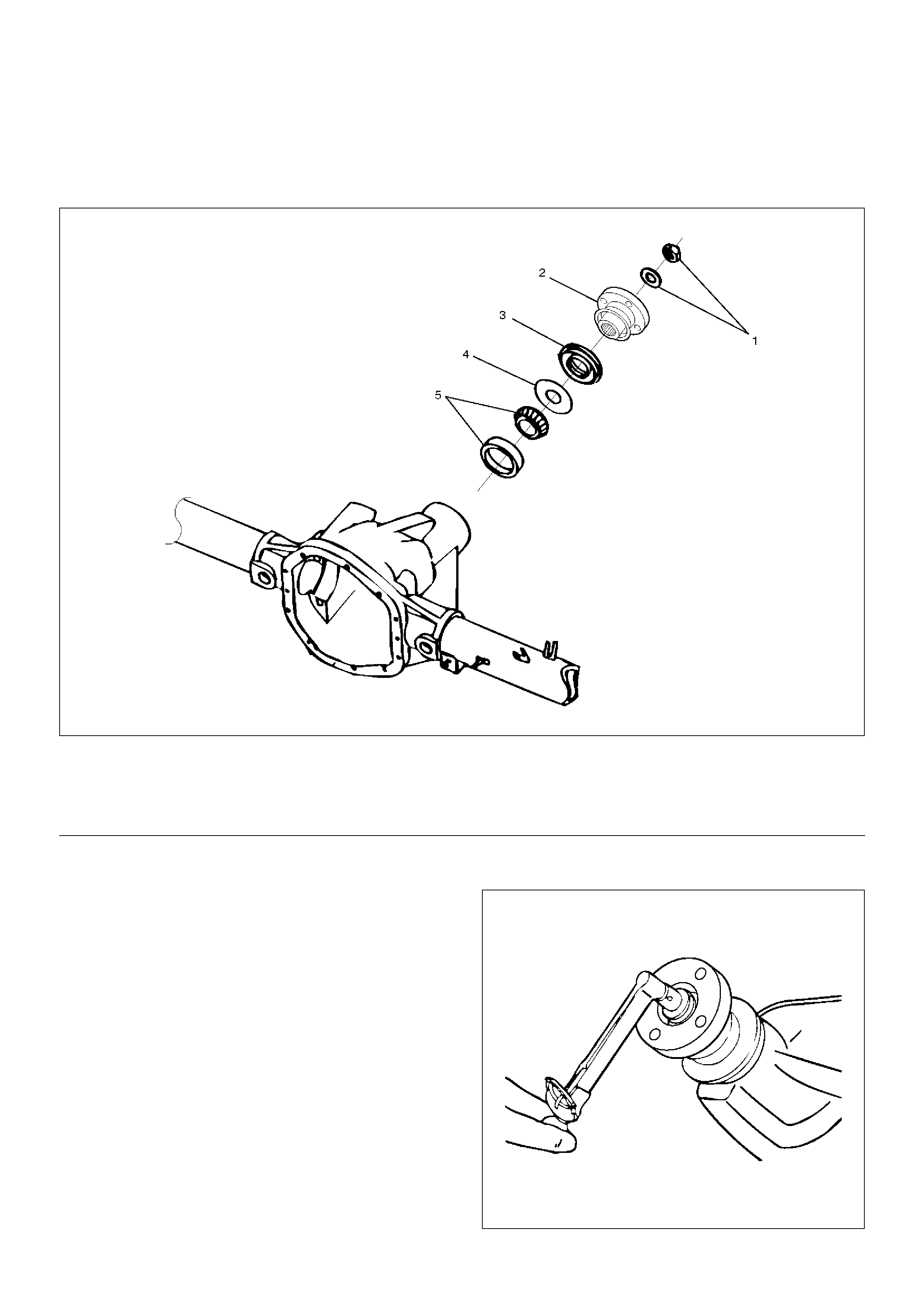
Removal
1.Remove the rear propeller shaft. Refer to Rear
Propeller Shaft in this section.
2. Drain the rear axle oil.
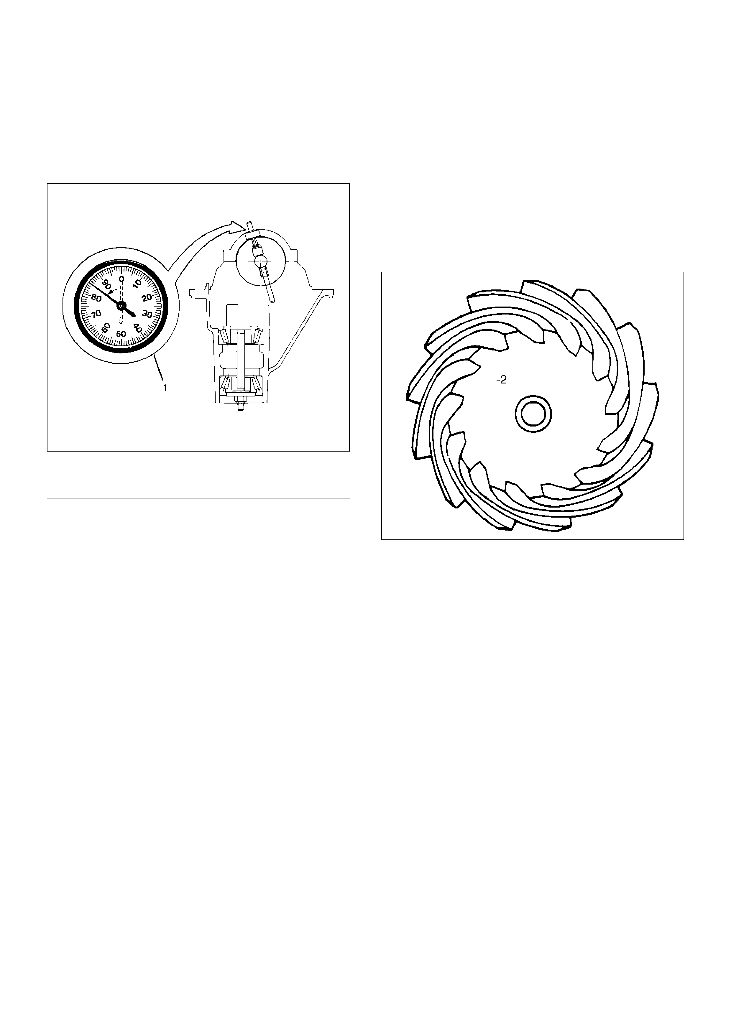
3. Check and record preload with an inch pound
torque wrench. This will give combined pinion
bearing, seal, carrier bearing, axle bearing and seal
preload.
425RW018
(1) Flange Nut and Washer
(2) Flange
(3) Oil Seal
(4) Outer Oil Seal Slinger
(5) Outer Pinion Bearing (Cup and Cone)
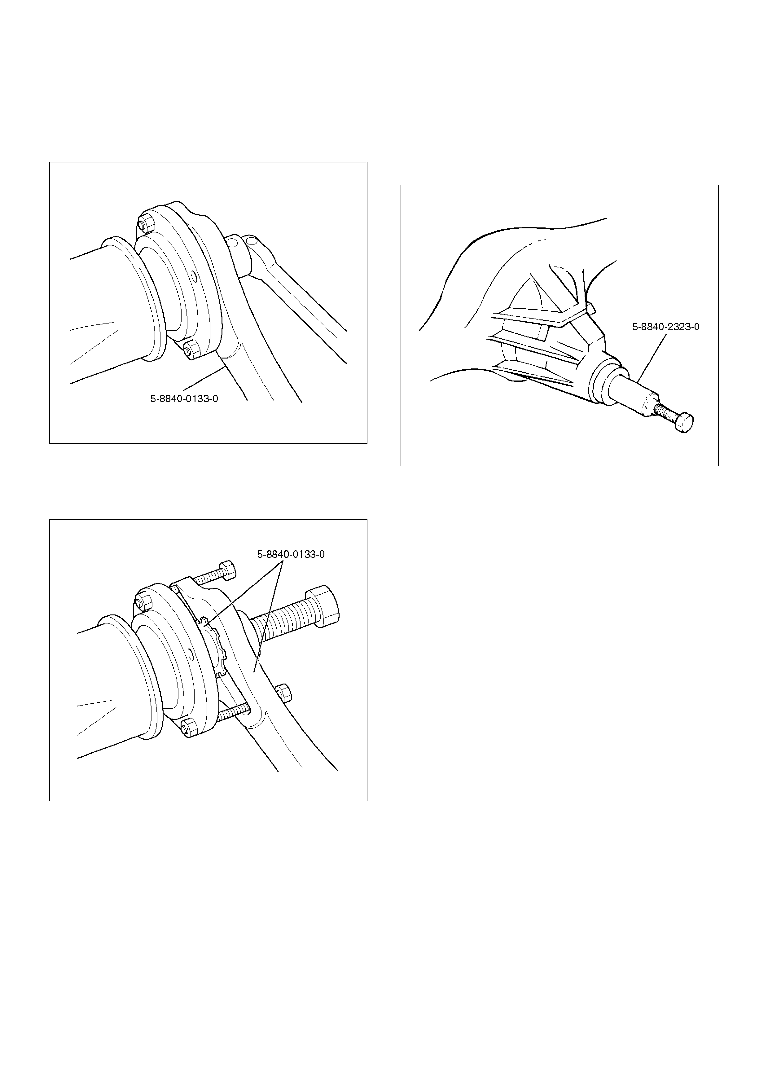
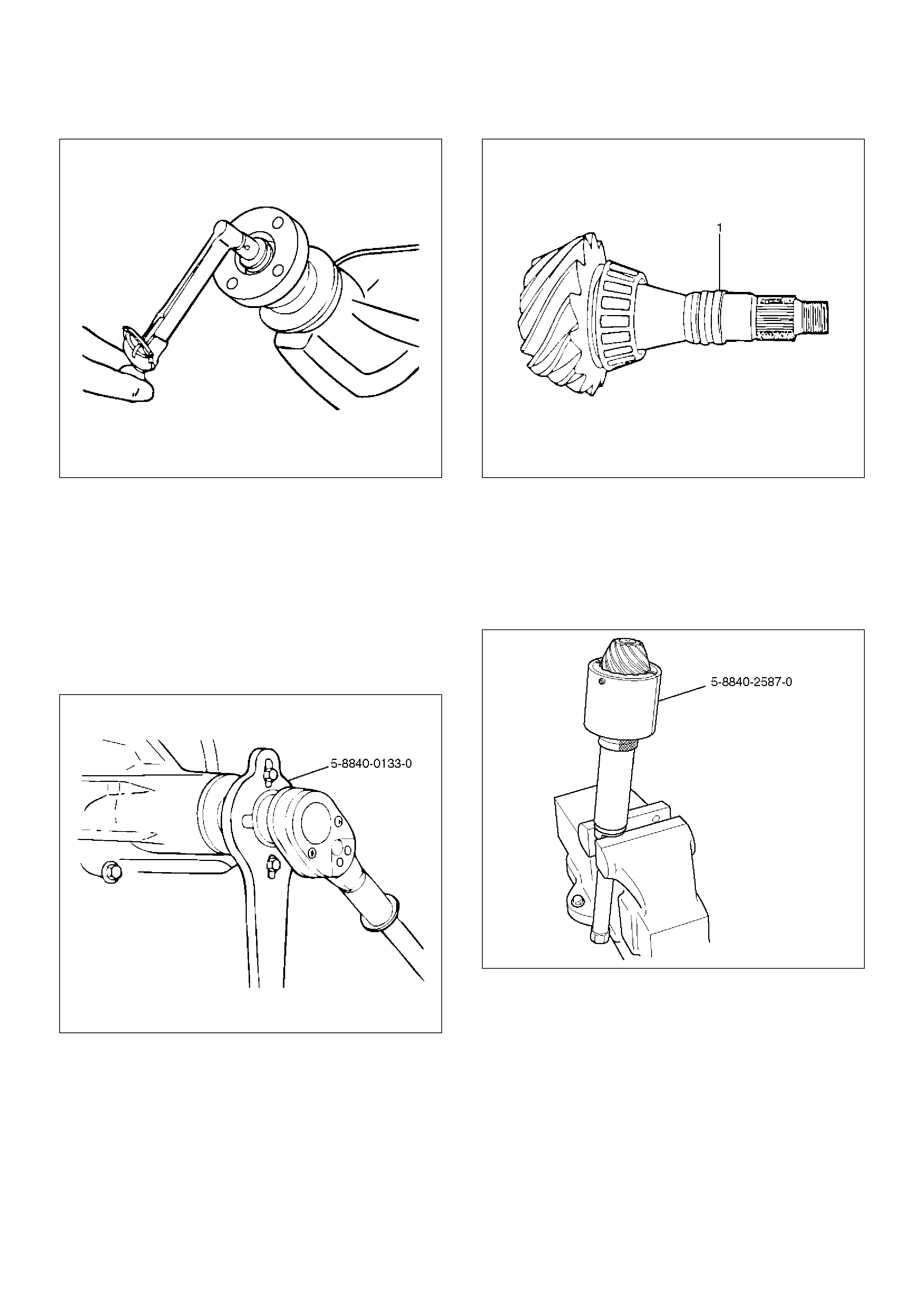
4. Remove flange nut and washer by using pinion
flange holder 5–8840–0133–0 after raising up its
staked parts completely.
425RW070
5. Remove flange by using 5–8840–0133–0.
• Have a suitable container in place to catch
lubricant.
425RW071
6. Remove oil seal.
7. Remove pinion oil seal slinger.
8. Remove outer bearing by using remover 5–8840–
2323–0.
425RW072
9. Remove collapsible spacer.
Inspection and Repair
Make necessary correction or parts replacement if wear,
damage, corrosion or any other abnormal condition are
found through inspection.
Check the following parts.
1. Seal surface of the flange.
2. Cage bore for burns.
Installation
1. Install collapsible spacer, discard the used
collapsible spacer and install a new one.
2. Install outer bearing.
NOTE: Do not drive in, but just temporarily set in the
outer bearing by hand, which should be indirectly
pressed in finally by tightening the flange nut.
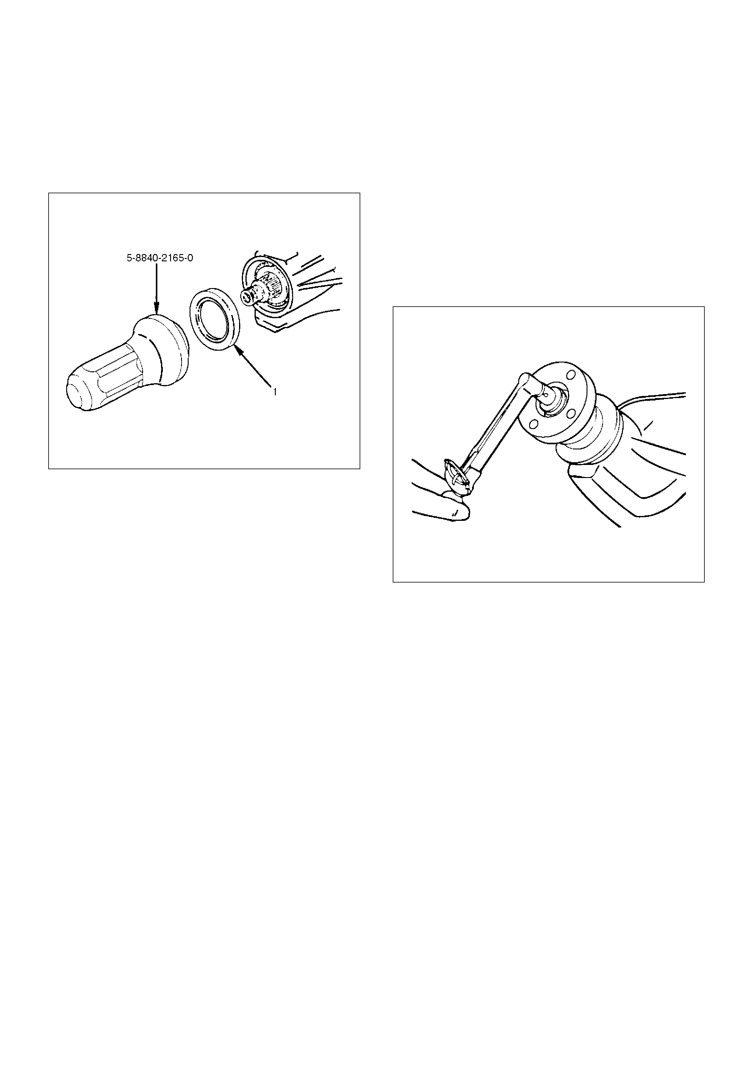
3. By using the seal installer 5–8840–2165–0, install a
new oil seal (1) that has grease on seal lip.
425RW050
4. Install flange.
5. The pinion washer and a new nut while holding the
pinion flange with 5–8840–0133–0.
• Tighten the nut until the pinion end play is just
taken up. Rotate the pinion while tightening the
nut to seat the bearings. Once there is not end
play in the pinion, the preload torque should be
checked.
• Remove 5–8840–0133–0. Using an inch-pound
torque wrench, check to make sure the pinion
preload is equal to or slightly over the reading
recorded during removal.
425RW018
6. Install propeller shaft to the frange.
7. Install bolt and nut. Tighten the bolt and nut to the
specified torque.
Torque: 63N·m (6.4kg·m/46lbft)
Differential Assembly
Disassembled View
420R100003
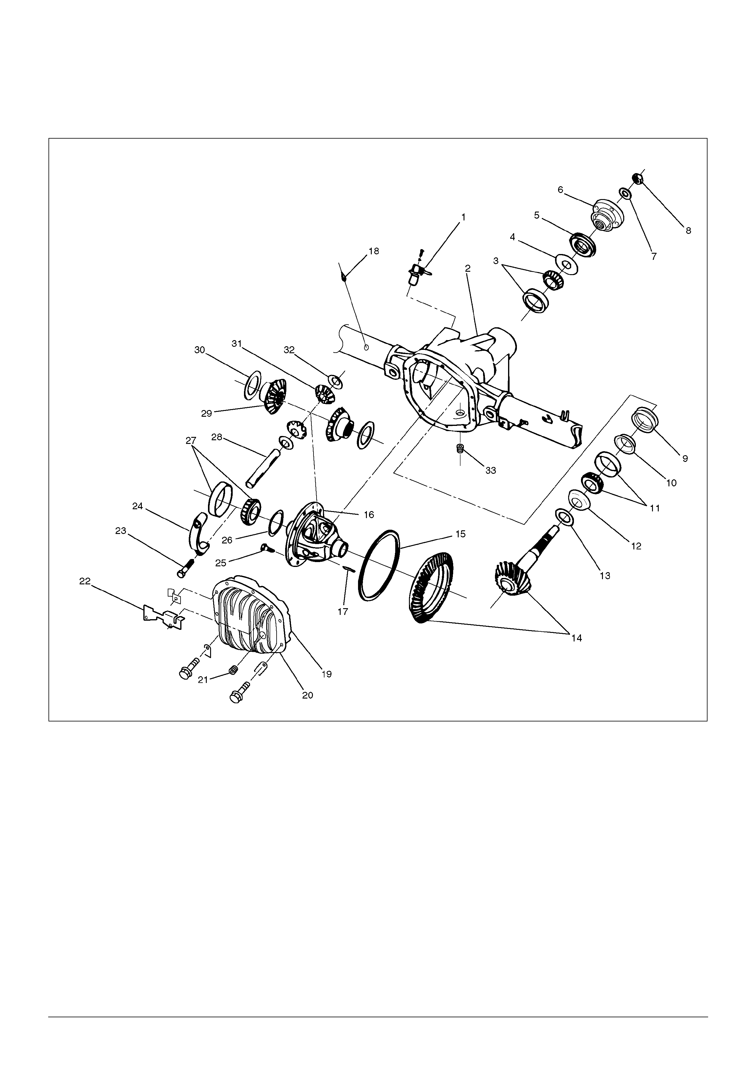
Legend
(1) ABS Speed Sensor
(2) Housing
(3) Outer Pinion Bearing (Cup and Cone)
(4) Outer Oil Slinger
(5) Oil Seal
(6) Companion Flange Assembly
(7) Pinion Nut Washer
(8) Pinion Nut
(9) Collapsible Spacer
(10) Baffle Plate
(11) Inner Pinion Bearing (Cup and Cone)
(12) Inner Oil Slinger
(13) Pinion gear adj. Shim-Selective (Position)
(14) Ring gear and Pinion Gear Assembly
(15) Exciter Ring
(16) Differential Case
(17) Lock Pin
(18) Axle Vent
(19) Gasket
(20) Cover and Clip Assembly
(21) Fill Plug (with Magnet)
(22) Mounting Bracket
(23) Side Bearing Cap Bolt
(24) Side Bearing Cap
(25) Drive Gear Bolts
(26) Differential Adjustment Shims (Side Bearing
Preload and Ring Gear/Pinion Backlash)
(27) Side Bearing (Cup and Cone)
(28) Differential Shaft
(29) Differential Side Gears
(30) Side Gear Thrust Washer
(31) Pinion Mate Gears
(32) Thrustwasher-Differential Pinion Mate Gear
(33) Drain Plug
Inspecting the Axle Before Disassembly
1.Remove the axle cover from the rear axle and drain
the axle lubricant into a suitable container.
2.Check ring gear backlash. Refer to “Backlash
Adjustment" in this section. This information can be
used to determine the cause of the axle problem. It
will also help when setting up the shim packs for
locating and preloading the differential cage.
3.Check case for metal chips and shavings.
Determine where these ships and shavings come
from, such as a broken gear or bearing cage.
•If possible, determine the cause of the axle
problem before disassembly.
Disassembly
1.Remove axle shafts.
•Refer to axle shaft replacement in this section.
2.Remove ABS sensor.
3.Remove bearing caps and bolts.
•Mark the caps and the housing as left and right.
CAUTION: Bearing caps are machined with the
housing and must be assembled in the same
position as removed. Note the matched letter
stamped on the caps and carrier. When assembled,
the letters on the caps must agree in both the
hosizontal and vertical position with the letters on
the carrier.
420RW003
4.Remove Differential case.
•Pry the case from the axle housing at the
differential “window".
420RW010
5.Remove side bearing outer races and shims.
•Mark the races and shims as left and right, and
place them with the bearing cups.
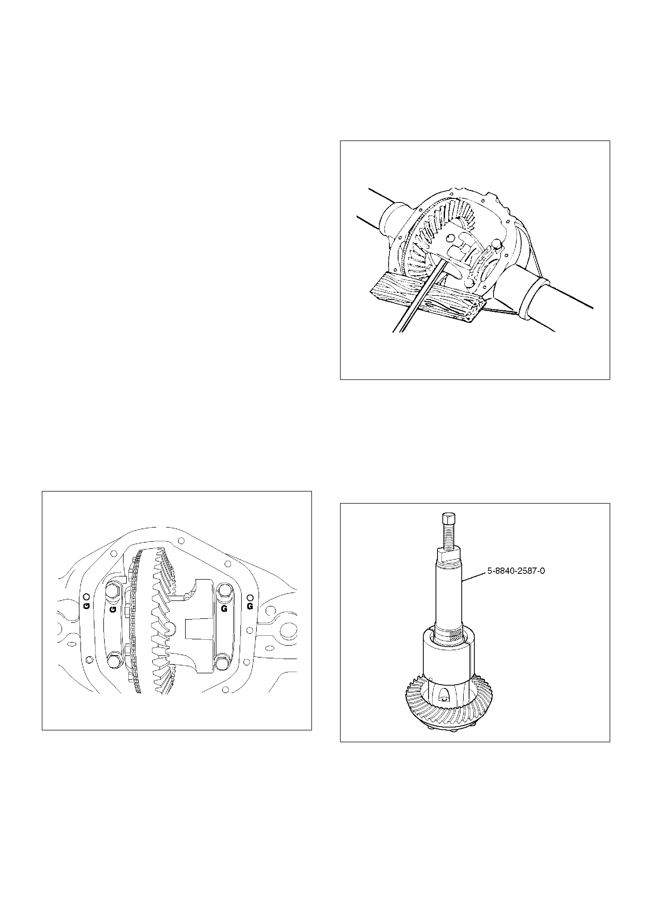
6.Remove differential side bearings using remover 5–
8840–2587–0 and plug 5–8840–2585–0.
•Select insert ; 303174 and collet halves ; 44801 in
remover kit 5–8840–2587–0.
415RW041
7.Remove ring gear bolts.
•Ring gear bolts use right handed threads.
CAUTION: Do not pry the ring gear from the case.
This will damage the ring and the differential case.
8. Remove ring gear from the differential.
• Drive the ring gear off with a brass drift if
necessary.
• Check drive pinion bearing preload.
425RW018
• Check the pinion assembly for looseness by
moving it back and forth. (Looseness indicates
excessive bearing wear.)
9. Remove pinion flange nut and washer.
• Use flange holder 5–8840–0133–0 to hold the
pinion flange.
10. Remove pinion flange.
• Use flange holder 5–8840–0133–0 to remove the
pinion flange.
415RW040
11. Remove pinion from the axle housing.
• Thread the pinion nut halfway onto the pinion.
• Drive the pinion out of the housing with a hammer
and a soft drift.
• Remove the nut and then remove the pinion.
12. Remove collapsible spacer(1).
415RW011
13. Remove outer seal, outer oil slinger and outer pinion
bearing.
14. Remove inner bearing, inner oil slinger and shim
from the pinion.
• Press the bearing off the pinion using remover 5–
8840–2587–0.
415RW042
• Select insert ; 303174 and collet halves ; 44801 in
remover kit 5–8840–2587–0.
• Remove the shim.
15. Remove bearing cups and baffle plate from the axle
housing using a hammer and a punch.
• Work the cups out of the housing evenly, moving
the punch back and forth between one side of the
cup and the other.
• The baffle plate will be destroyed and should be
replaced with a new one.
16. Remove exciter ring.
• Remove the exciter ring from the differential
using a mallet or a brass hammer if it is required.
NOTE: Discard the exciter ring after removal.
425RS097
Cleaning
Do not steam clean drive parts which have ground and
polished surfaces such as gears, bearings, and shafts.
These parts should be cleaned in a suitable solvent. All
parts should be disassembled before cleaning.
Parts should be thoroughly dried immediately after
cleaning. Use soft, clean, lintless rags. Parts may be
dried with cimpressed air. Do not allow the bearings to
spin while drying them with compressed air.
Inspection and Repair
It is very important to carefully and thoroughly inspect all
drive unit parts before reassembly.
Thorough inspection of the drive parts for wear or stress
and subsequent replacement of worn parts will
eliminate costly drive component repair after
reassembly.
Axle Housing
• The carrier bore for nicks or burrs that would prevent
the outer diameter of the pinion seal from sealing,
Remove any burrs that are found.
• The bearing cap bores for nicks or burrs.
Remove any burrs that are found.
• The housing for cracks. Replace the housing if any
cracks are found.
• The housing for foreign material such as metal chips,
dirt, or rust.
Pinion and Ring Gear
• Pinion and ring gear teeth for cracking, chipping,
scoring, or excessive wear.
• Pinion splines for wear.
• Pinion flange splines for wear.
• The sealing surface of the pinion flange for nicks,
burrs, or rough tool marks which would cause
damage to the seal's inside diameter and result in an
oil leak.
• Replace all worn or broken parts.
• Ring and pinion gears are matched sets and are both
replaced anytime a replacement of either is
necessary.
Bearings
• Bearings visually and by feel.
• The bearings should feel smooth when oiled and
rotated while applying as much hand pressure as
possible.
The large end of the bearing rollers for wear.
This is where tapered roller bearing wear is most
evident.
• Bearing cups for wear, cracks, brinelling and scoring.
• Bearing and cups are only replaced as sets.
• If the rear axle was operated for an extended period
of time with very loose bearings, the ring gear and
drive pinion will also require replacement.
• Low mileage bearings may have minute scratches
and pits on the rollers and the bearing cups from the
initial pre-load. Do not replace a bearing for this
reason.
• Bearing cups for cracks or chips.
Shims
• Shims for cracks and chips. Damaged shims should
be replaced with an equally sized service shim.
Reassembly
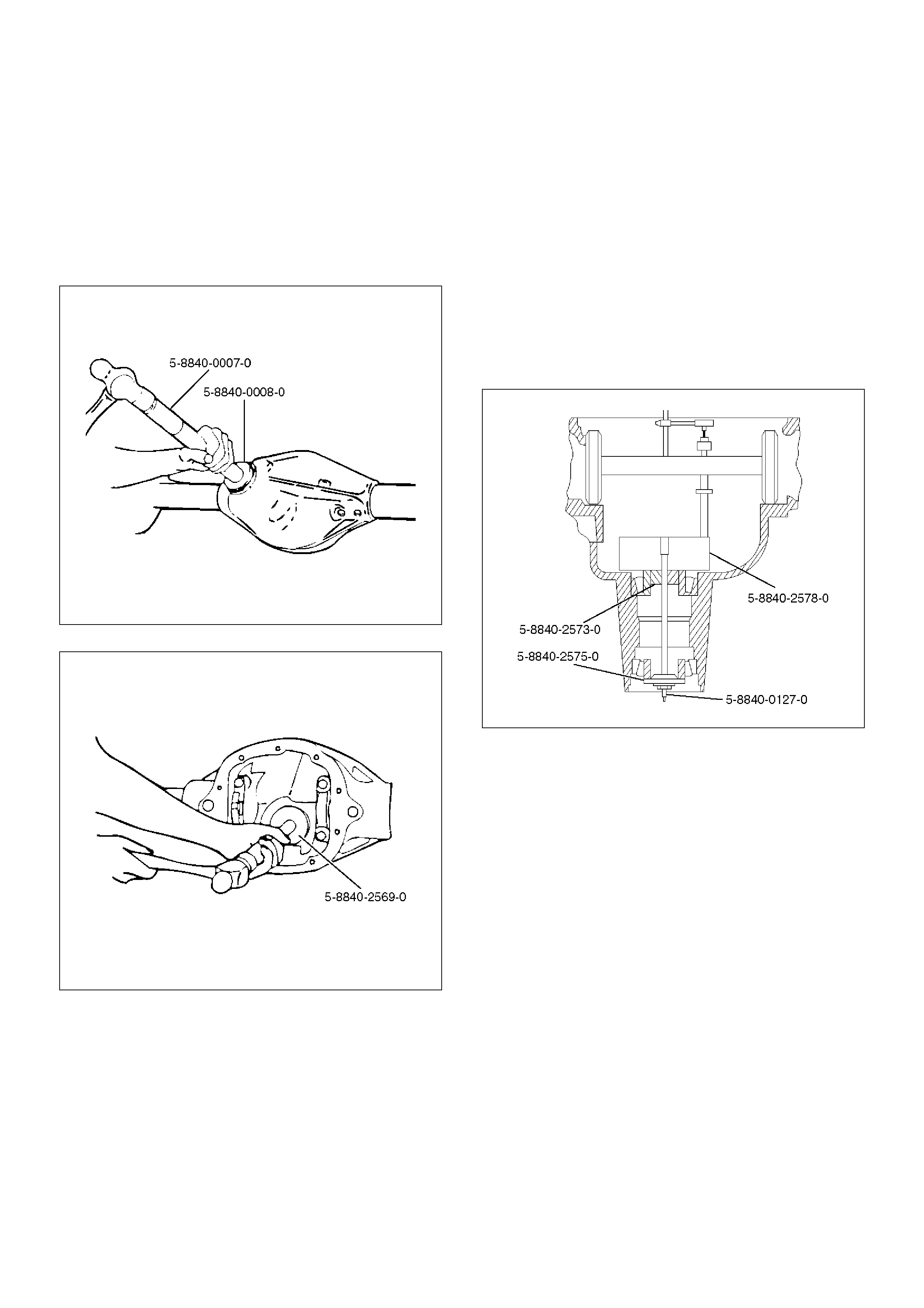
1. Install pinion bearing races and baffle plate using
outer bearing race installer 5–8840–0008–0 / inner
bearing race installer 5–8840–2569–0 and drive
handle 5–8840–0007–0.
NOTE: Baffle plate must be installed, when install the
inner pinion bearing race.
425RW073
425RW074
2. Clean all the gauge parts.
3. Lubricate the outer and inner bearings with axle
lubricant.
4. Place the bearings into the pinion bearing races.
5. Place the inner oil slinger onto the inner pinion
bearing.
NOTE: The inner oil slinger must be placed between
gauge plate and inner pinion bearing when measuring
the pinion depth.
6. Install gauge plate 5–8840–2578–0, inner pilot 5–
8840–2573–0 stud and nut 5–8840–0127–0 and
outer pilot 5–8840–2575–0 to the pinion bore.
420RW075
7. Hold the stud stationary at the flats of the stud (and).
Tighten the stud nut
Torque: 2.2N·m (0.2kg·m/1.6lbft)
8. Rotate the gauge plate and bearings several
complete revolutions to seat the bearings.
9. Tighten the stud nut until a torque of 1.6 to 2.2 N·m
(0.16 – 0.22kg·m/1.2 to 1.6lbft.) is required to keep
the gauge plate in rotation.
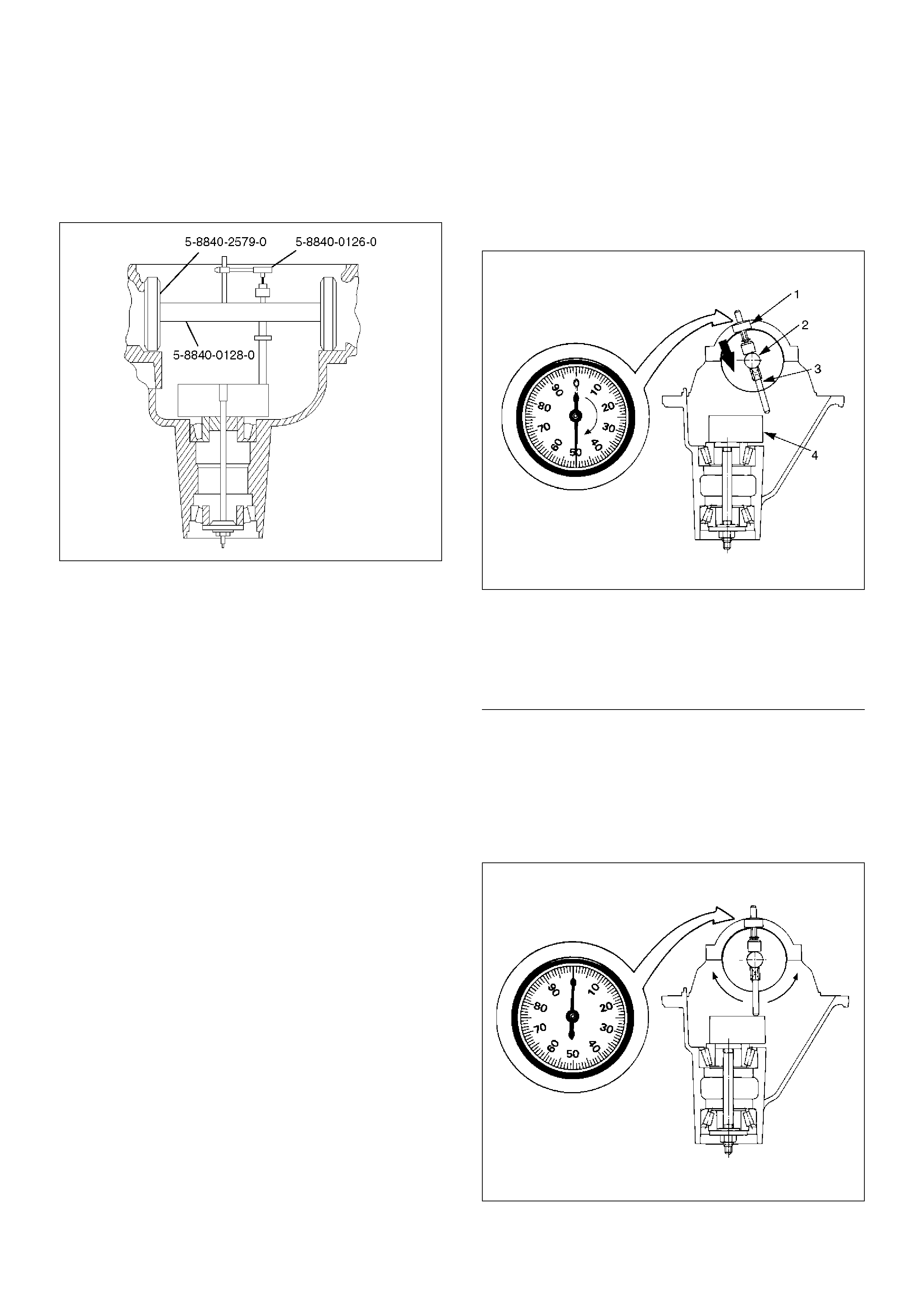
10. Assemble discs 5–8840–2579–0, arbor 5–8840–
0128–0 and dial indicator 5–8840–0126–0 to the
side bearing bores.
NOTE: The bearing bores must be clean and burr-free.
420RW076
11. Install the side bearing caps and tighten the bolts to
the specified torque.
Torque: 108N·m (11.0kg·m/80lbft)
12. Rotate the gauge plate until the gauging area is
parallel with the discs.
13. Position the arbor assembly in the carrier so that the
plunger is centered on the gauge area of the gauge
plate.
14. Set the dial indicator to “0". Place it on the mounting
post of the gauging arbor with the contact button
touching the indicator pad.
Force the dial indicator downward until the needle
has made a half turn clockwise. Tighten down the
dial indicator in this position.
425RS020
Legend
EndOFCallout
15. Position the plunger on the gauge plate. Move the
gauging arbor slowly back and forth and locate the
position at which the dial indicator shows the
greatest defection. At this point, once again set the
dial indicator to “0".
Repeat the procedure to verify the “0" setting.
425RS021
(1) Dial Indicator
(2) Ganging Arbor
(3) Plunger
(4) Gaug Plate
16. After the ZERO setting is obtained, rotate the
gauging arbor until the dial indicator rod does not
touch the gauging plate.
Record the number the dial indicator needle points
to.
425RS022
Legend
EndOFCallout
17. Record the pinion depth code on the head of the
drive pinion.
The number indicates a necessary change in the
pinion mounting distance. A plus number indicates
the need for a greater mounting distance (which can
be achieved by decreasing the shim thickness). A
minus number indicates the need for a smaller
mounting distance (which can be achieved by
increasing the shim thickness). If examination
reveals pinion depth code “0", the pinion is
“nominal".
425RS023
(1) Example=Dial indicator reading of 0.085

18. Select the shim using the chart;
Dial Indicator
Reading
(inches)
Marking (inches)
+3 +2 +1 0 -1 -2 -3
0.027 0.030
0.028 0.030 0.031
0.029 0.030 0.031 0.032
0.030 0.030 0.031 0.032 0.033
0.031 0.030 0.031 0.032 0.033 0.034
0.032 0.030 0.031 0.032 0.033 0.034 0.035
0.033 0.030 0.031 0.032 0.033 0.034 0.035 0.036
0.034 0.031 0.032 0.033 0.034 0.035 0.036 0.037
0.035 0.032 0.033 0.034 0.035 0.036 0.037 0.038
0.036 0.033 0.034 0.035 0.036 0.037 0.038 0.039
0.037 0.034 0.035 0.036 0.037 0.038 0.039 0.040
0.038 0.035 0.036 0.037 0.038 0.039 0.040 0.041
0.039 0.036 0.037 0.038 0.039 0.040 0.041 0.042
0.040 0.037 0.038 0.039 0.040 0.041 0.042 0.043
0.041 0.038 0.039 0.040 0.041 0.042 0.043 0.044
0.042 0.039 0.040 0.041 0.042 0.043 0.044 0.045
0.043 0.040 0.041 0.042 0.043 0.044 0.045 0.046
0.044 0.041 0.042 0.043 0.044 0.045 0.046 0.047
0.045 0.042 0.043 0.044 0.045 0.046 0.047 0.048
0.046 0.043 0.044 0.045 0.046 0.047 0.048 0.049
0.047 0.044 0.045 0.046 0.047 0.048 0.049 0.050
0.048 0.045 0.046 0.047 0.048 0.049 0.050 0.051
0.049 0.046 0.047 0.048 0.049 0.050 0.051 0.052
0.050 0.047 0.048 0.049 0.050 0.051 0.052 0.053
0.051 0.048 0.049 0.050 0.051 0.052 0.053
0.052 0.049 0.050 0.051 0.052 0.053
0.053 0.050 0.051 0.052 0.053
0.054 0.051 0.052 0.053
0.055 0.052 0.053
0.056 0.053
19. Remove bearing caps and depth gauging tools.
20. Install the correct pinion shim and inner oil slinger
onto pinion.
NOTE: Do not install pinion gear into housing at this
time.
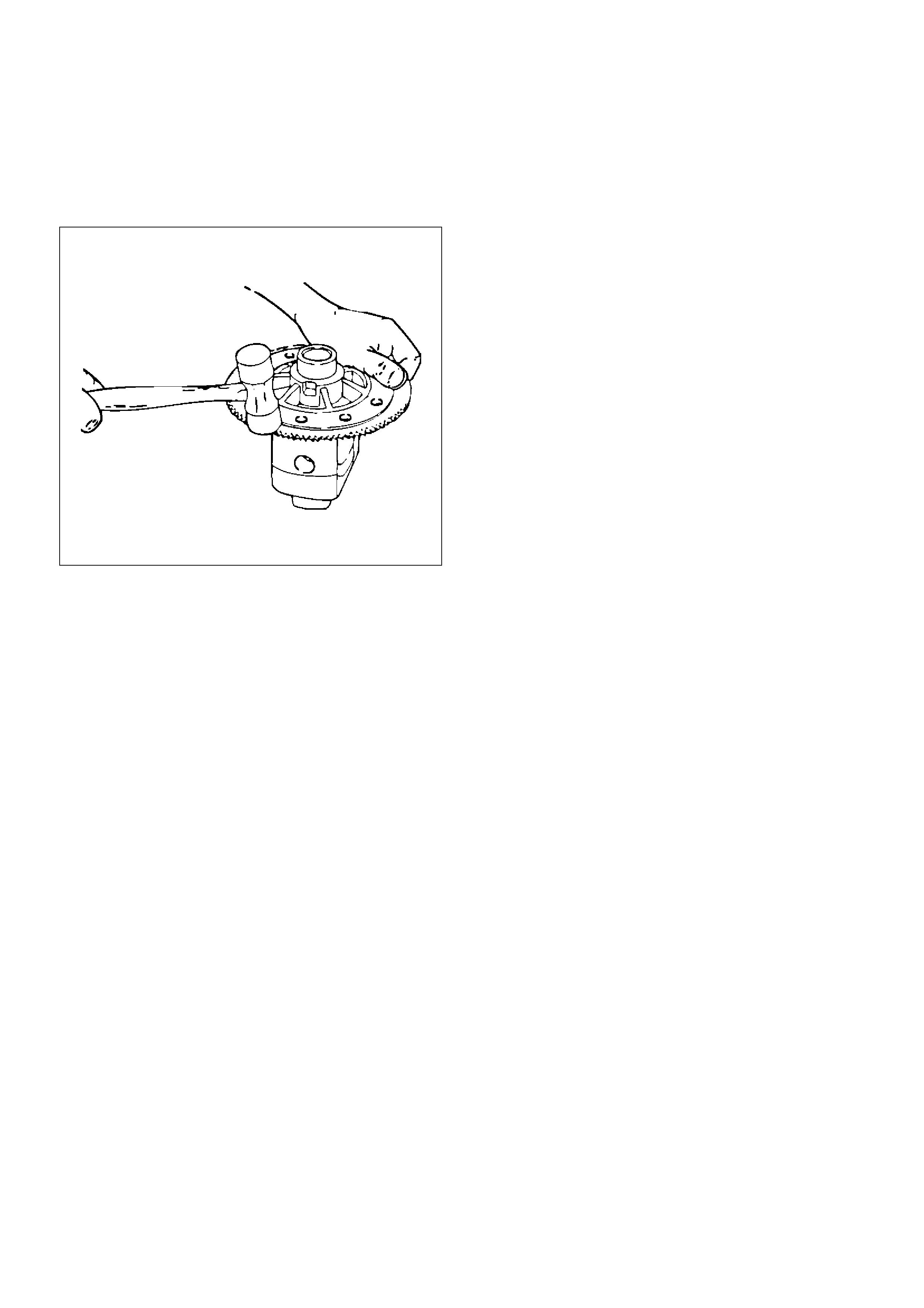
21. If the exciter ring was removed, install the new
exciter ring onto the differential case by pressing
using the ring gear as a pilot.
425RS047
22. Install ring gear(1) to the differential case(2)
425RW021
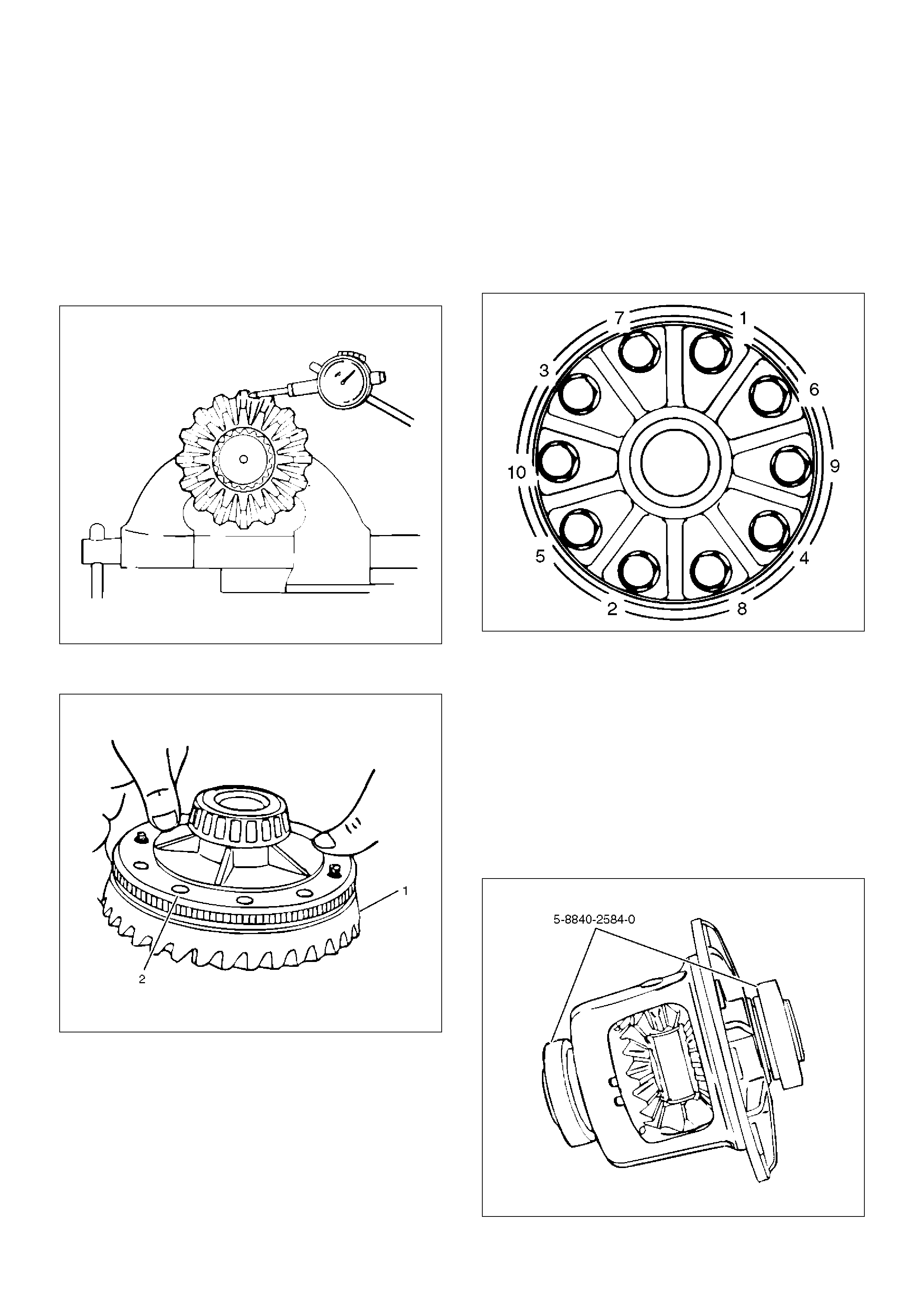
23. Install new ring gear bolts.
• Tighten the ring gear bolts alternately in stages,
gradually pulling the ring gear onto the differential
case.
Tighten the ring gear bolts in sequence
Torque: 108N·m (11.0kg·m/80lbft)
NOTE: Discard used bolts and install new ones.
415RS016
Side Bearing Preload Adjustment
1. The side bearing preload adjustment must be made
before installing the pinion.
2. The side bearing preload is adjusted by changing
the thickness of both hte left and right shims equally.
This maintain the original backlash.
3. Install master side bearings 5–8840–2584–0 onto
the case.
Remove all nicks, burrs, dirt etc., from the hubs to
allow the master bearings to rotate freely.
425RW077

4. Assemble the differential case into the housing (less
pinion). Install bearing caps and finger tight bolts.
Mount a dial indicator with a magnetic base to the
housing and indicate on the flange or head of screw.
Force the differential assembly as far as possible in
the dirction towards the indicator.
With force still applied, set indicator at zero(0).
NOTE: Dial indicator set should be capable of a
minimum travel of 5.08mm (0.2in).
425RS107
5. Force the differetial assembly as far as it will go in
the opposite direction. Repeat these steps until the
same reading is obtained.
6. Record the reading of the indicator.
This amount, in shims, will be included in the final
assembly shim stack to establish side bearing
preload and ring gear and pinion backlash.
7. After marking sure the readings are correct, remove
the indicator and differetial assembly from the
housing.
Pinion Installation
• The bearing cups should have been installed in
Pinion Depth Adjustment in this section.
1. Place the shim(1) and inner oil slinger(2) on the
pinion gear, then install the pinion inner bearing(3)
using installer 5–8840–2574–0.
425RW078
• Drive the bearing until the bearing cone seats on
the pinion shims.
2. Install a new collpsible spacer.
• Lubracate the pinion bearings with axle lublicant.
3. Install pinion to the axle housing.
4. Install outer pinion bearing onto the pinion.
• Hold the pinion forward from inside the case
while driving the bearing onto the pinion.
5. Install oil seal slinger.
6. Install pinion oil seal using installer 5–8840–2165–0.
7. Install the pinion flange to the pinion by tapping it
with a rawhide hammer until a few threads show
through the pinion flange.
8. Install pinion washer and a new nut while holding
the pinion flange with flange holder 5–8840–0133–
0.
• Tighten the nut until the pinion end play is just
taken up. Rotate the pinion while tightening the
nut to seat the bearings.
Torque:217-678N·m (22.1-69.1kg·m/160-500lbft)
Once there is no end play in the pinion, the
preload torque should be checked.
• Remove flange holder 5–8840–0133–0. Using a
torque wrench, check the pinion preload by
rotating the pinion with the wrench.
425RW018
Preload should be at 1.0 to 1.6N·m
(10.2-16.3kg·cm/8 to 14inlbs.) on new bearings,
or 0.46 to 0.69N·m (4.7-7.0kg·cm/4 to 6inlbs.) for
used bearings.
• If the preload torque is below the preloads given
above, continue torquing the nut in small
increments. Check the preload after each
tightening. Each tightening increases the bearing
preload by several pounds. If the bearing preload
is exceeded, the pinion will have to be removed,
and a new collapsible spacer installed.
• Once a preload of 1.0 to 1.4N·m
(10.2-14.3kg·cm/8 to 12inlbs.) has been
obtained, rotate the pinion several times to
assure that the bearings have seated. Recheck
the preload, and adjust if necessary.
Determination of Backlash & Preload
Shims
1. Install master side bearings onto the case.
2. Install differential assembly into the carrier.
3. Install the bearing cap and finger tight bolts.
4. Set up the dial indicator.
5. Force the differential assembly away from the pinion
gear until it is completely seated against the cross
bore face of the carrier.
6. With force still applied to the differential case, place
the tip of dial indicator on a machined surface of the
differential case, if available, or on the head of a ring
gear screw, and set the indicator at zero(0).
7. Force the ring gear to mesh with the pinion gear.
Rock the ring gear slightly to make sure the gear
teeth are meshed. Repeat this procedure several
times until the same reading is obtained each time.
Be sure the indicator reads zero(0) each time the
ring gear is forced back into contact with the cross
bore face. This reading will be the necessary
amount of thims to be placed between the
differential case and side bearing cone on the ring
gear side.
8. The remaining amount of shims, which is the
difference between the overall found in step 6 of
Side Bearing Pre-load Adjustment and step(7)
above, should be placed on the other side of the
differential case, plus additional 0.38mm (0.015in)
for obtaining preload and backlash.
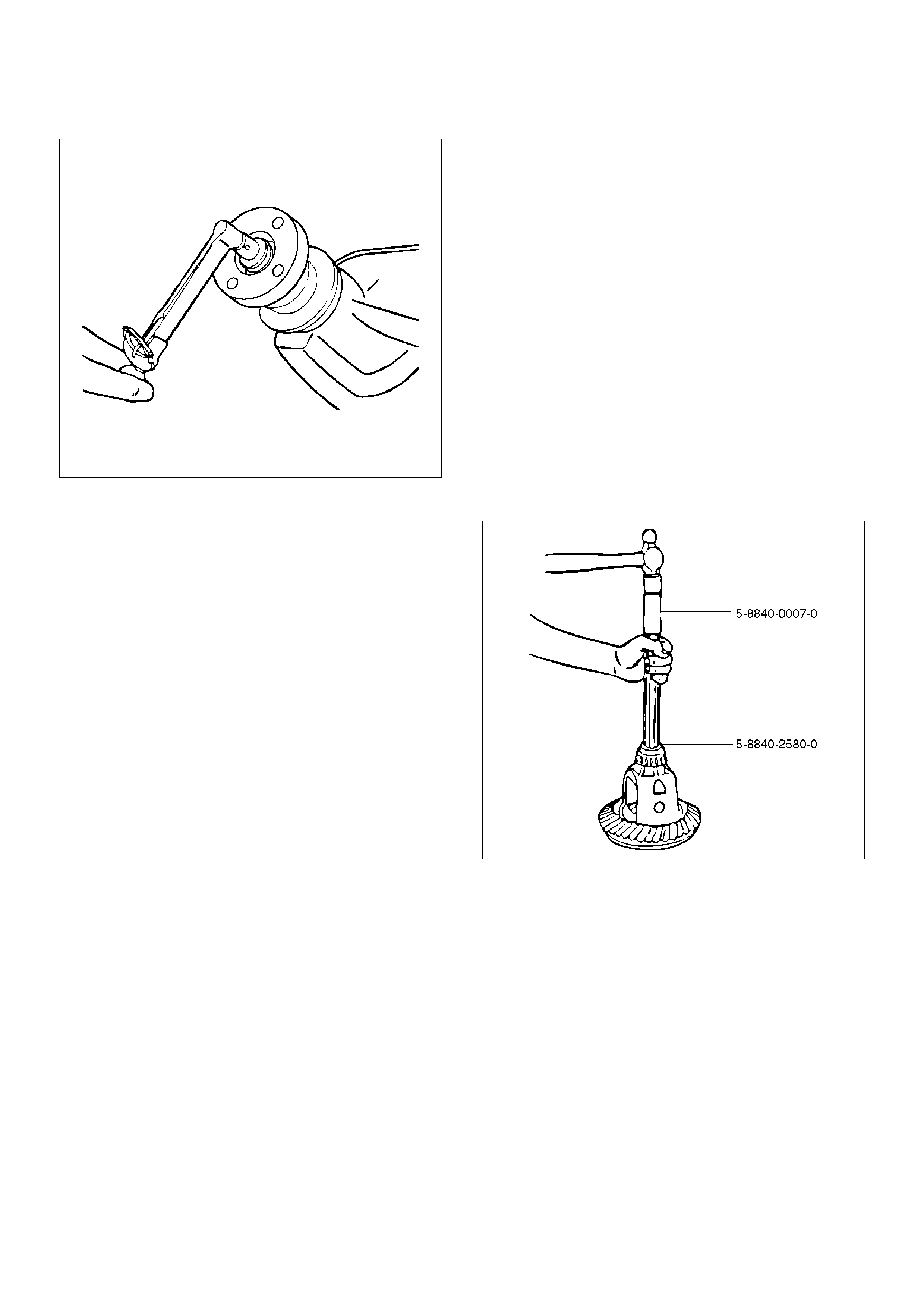
9. Place the required amount of shims on each hub as
determined in the previous steps and assemble side
bearing cone by using installer 5–8840–2580–0 and
handle 5–8840–0007–0.
425RW079
10. Total torque to rotate — Increase of pinion torque to
rotate due to differential case assembly shall not
exceed 3.4N·m (34.7kg·cm/30inlbs.) divided by the
gear ratio.
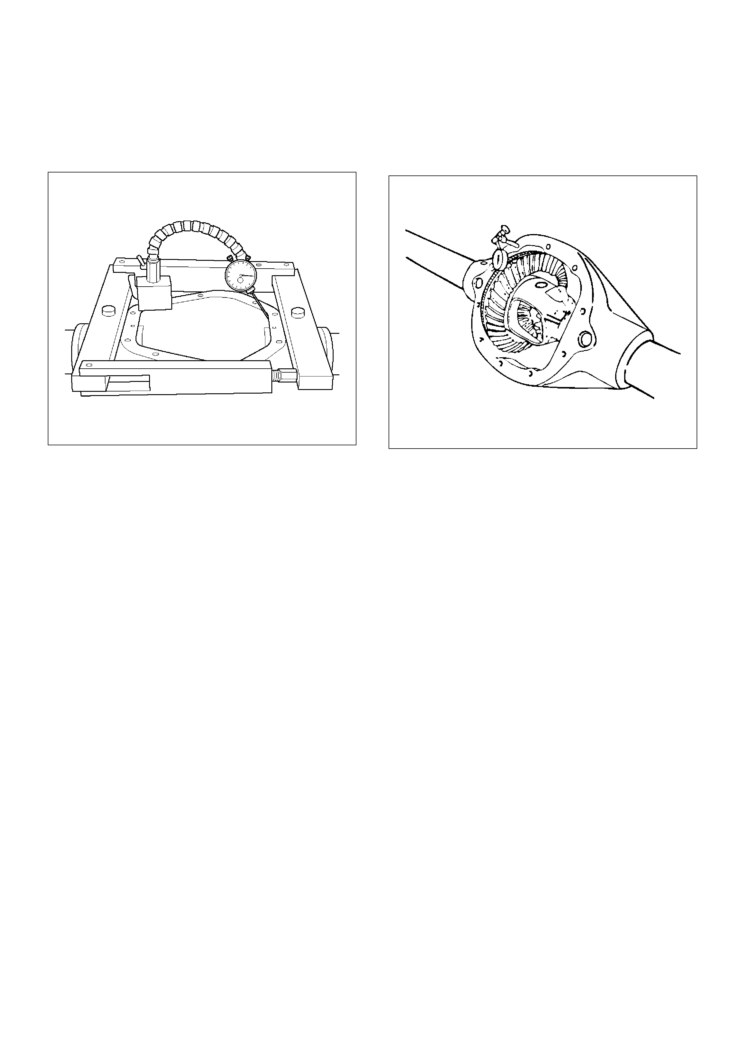
11.Assembly the spreader 5–8840–2581–0 and
indicator to the carrier as shown in figure. Spread
the carrier 0.5mm (0.02in) for differential
installation.
420RW004
CAUTION: Do not spread the carrier over 0.5mm
(0.02in).
12. Remove the indicator.
Backlash Adjustment
1. Install the differential case assembly and bearing
caps.
2. Rotate the case several times to seat the bearings.
3. Remove the spreader.
4. Install the side bearing cap bolts.
Tighten side bearing cap bolts
Torque: 108N·m (11.0kg·m/80lbft)
5. Install a dial indicator to the case using a magnetic
base.
6. Place the indicator stem at the heel end of a tooth.
• Set the dial indicator so that the stem is in line
with the gear rotation and perpendicular to the
tooth angle.
425RS087
7. Check and record the backlash at three points
around the ring gear.
• The pinion must be held stationary when
checking backlash.
• The backlash should be the same at each point
within 0.07mm (0.003in). If the backlash varies
more than 0.07mm (0.003in), check for burrs, a
distorted case flange, or uneven bolting
conditions.
8. Backlash at the minimum lash point measured
should be between 0.13 and 0.20mm (0.005 and
0.008in) for all new gear sets.
9. If the backlash is not within specifications, move the
ring gear in or out from the pinion by increasing the
thickness of one shims, and decreasing the
thickness of the other shim by the same amount.
This will maintain the correct rear axls side bearing
preload.
• Moving 0.05mm (0.002in) worth of shim from one
side of the differential to the other will change the
backlash adjustment by 0.03mm (0.001in).
10. After obtaining correct tooth contact described in
later, install ABS speed sensor.
11. Install the cover with sealant.
Torque: 42N·m (4.3kg·m/31lbft)
12. Fill the axle lubricant.
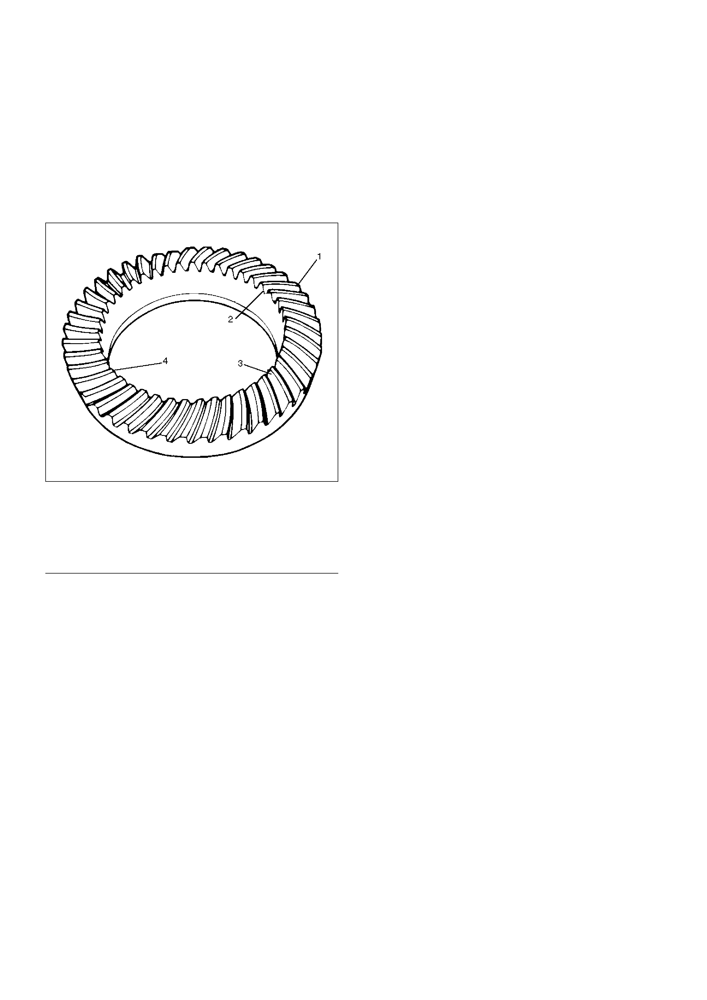
Gear Tooth Pattern Check
Checking the ring gear to pinion tooth pattern is to be
done only after setting up the axle according to the
methods in this section. The pattern check is never to
be used as an initial check, or instead of checking
pinion depth and backlash adjustments.
This check is only to be verify the correct adjustment of
the gear set after set up.
425RS038
Legend
EndOFCallout
1. Wipe all oil out of the carrier, and carefully clean
each tooth of the ring gear.
2. Use gear marking compound 1052351 or equivalent
and apply this mixture sparingly to all ring gear
teeth, using a medium-stiff brush. When properly
used, the area of pinion tooth contact will be visible
when hand load is applied.
3. Tighten the bearing cap bolts to the specified
torque.
4. Expand the brake shoes until a torque of 54 to
68N·m (5.5 to 6.9kg·m/40 to 50 lbft.) is required to
turn the pinion. A test made without loading the
gears will not give a satisfactory pattern. Turn the
pinion flange with a wrench so that the ring gear
rotates one full revolution, then reverse the rotation
so that the ring gear rotates one revolution in the
opposite direction.
(1) Heel
(2) Toe
(3) Concave Side (Coast)
(4) Convex Side (Drive)
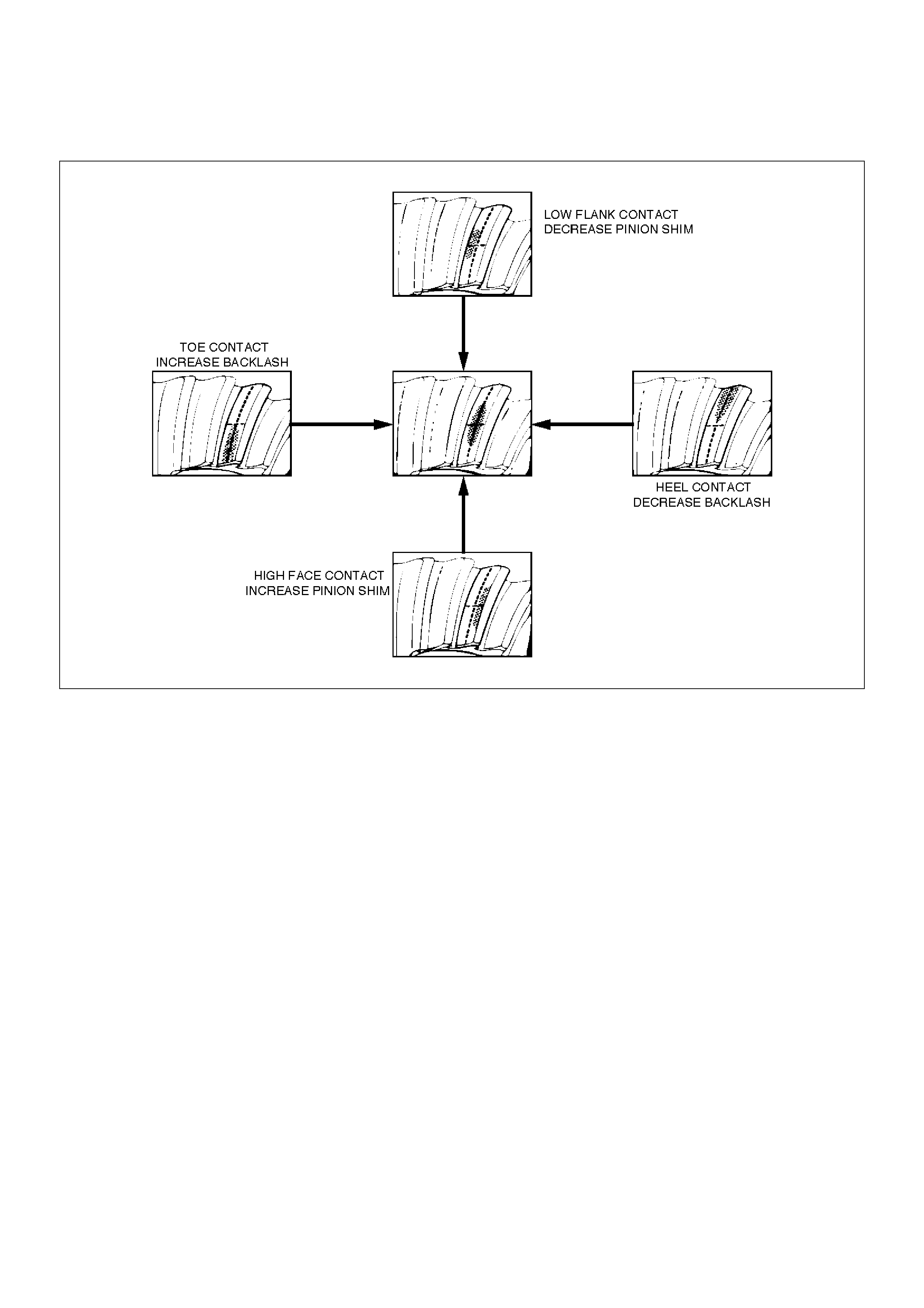
5. Observe the pattern on the ring gear teeth and
compare this with figure.
425RS039
Adjustments Affecting Tooth Contact
Two adjustments can be made which will affect tooth
contact pattern: backlash, and the position of the drive
pinion in the case. The effects of bearing preloads are
not readily apparent on head loaded tooth contact
pattern tests; however, these adjustments shuld be
within specifications before proceeding with backlash
and drive pinion adjustments.
The position of the drive pinion is adjusted by increasing
or decreasing the distance between the pinion head and
the centerline of the ring gear.
Decreasing the distance will move the pinion closer to
the centerline of the ring gear. Increasing the distance
will move the pinion farther away from the centerline of
the ring gear.
Backlash is adjusted by means of the side bearing
adjusting shims which move the entyre case and ring
gear assembly closer to, or farther from, the drive
pinion. (The adjusting shims are also used to set side
bearing preload.)
If the thickness of the right shim is increased (along with
decreasing the left shim thickness), backlash will
increase.
The backlash will decrease if the left shim thickness is
increased (along with a decrease in right shim
thickness).
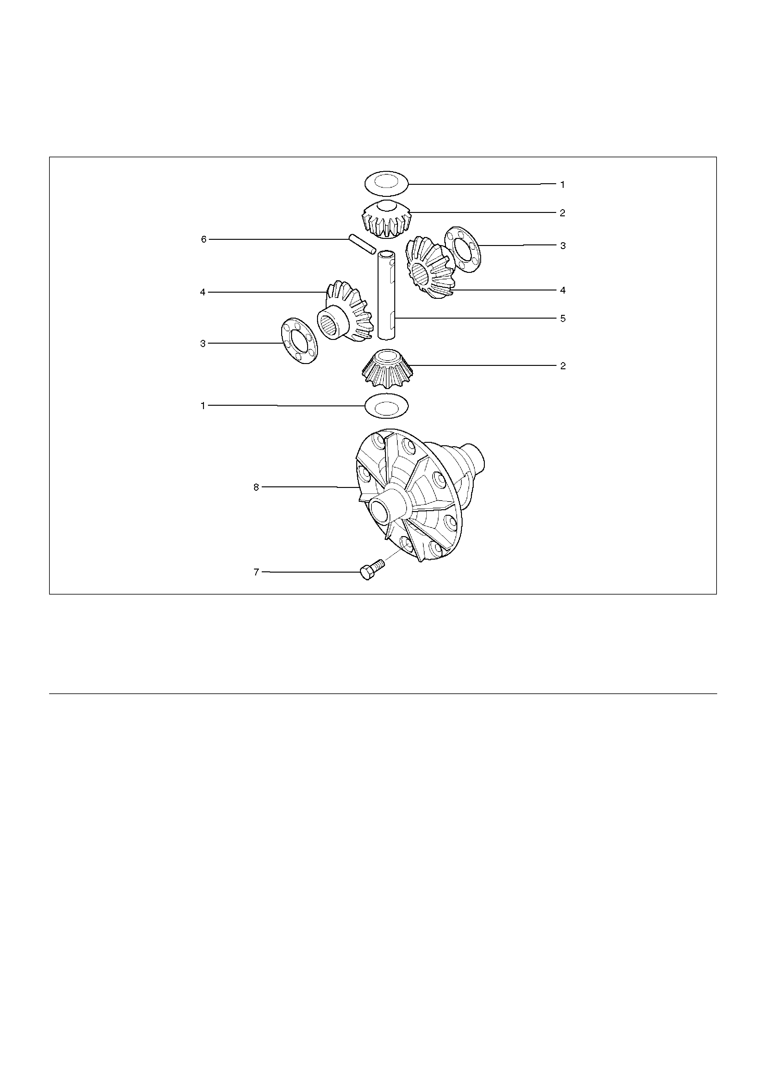
Differential Case Assembly
Disassembled View
425RW014
Legend
EndOFCallout
(1) Thrust Washer (for Pinion Gear)
(2) Pinion Mate Gear
(3) Thrust Washer(for Side Gear)
(4) Side Gear
(5) Differential Shaft
(6) Lock Pin
(7) Bolt
(8) Differential Case
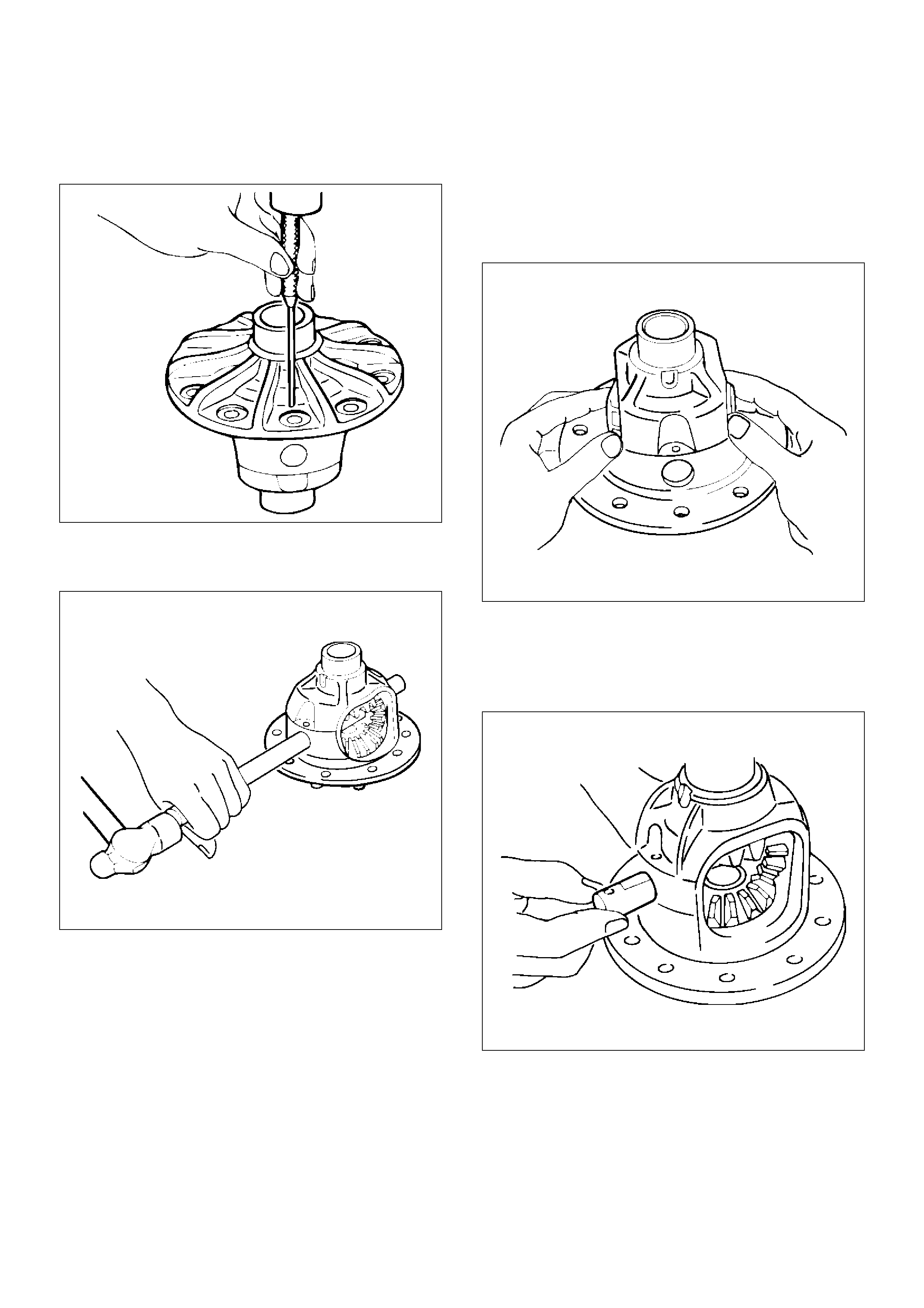
Disassembly
1. Remove lock pin using a small drift.
425RS098
2. Remove the differential shaft by using a soft metal
rod and a hammer.
425RS043
3. Remove pinion mate gear and thrust washer.
4. Remove side gear and thrust washer.
Inspection and Repair
Make necessary correction or parts replacement if wear,
damage, corrosion or any other abnormal condition are
found through inspection.
Check the following parts.
• Ring gear, pinion gear
• Bearing
• Side gear, pinion mate gear, differential shaft
• Differential case, carrier
• Thrust washer
• Oil seal
Reassembly
1. Install side gear with thrust washer.
2. Install the pinion mate gear with thrust washer by
engaging it with the side gears while turning both
pinion mate gears simultaneously in the same
direction.
425RS048
3. Install differential shaft.
1. Be sure to install the differential shaft so that it is
in alignment with the lock pin hole in the
differential case.
425RS049
4. Install lock pin.
After lock pin installation, stake the case to secure
the lock pin.
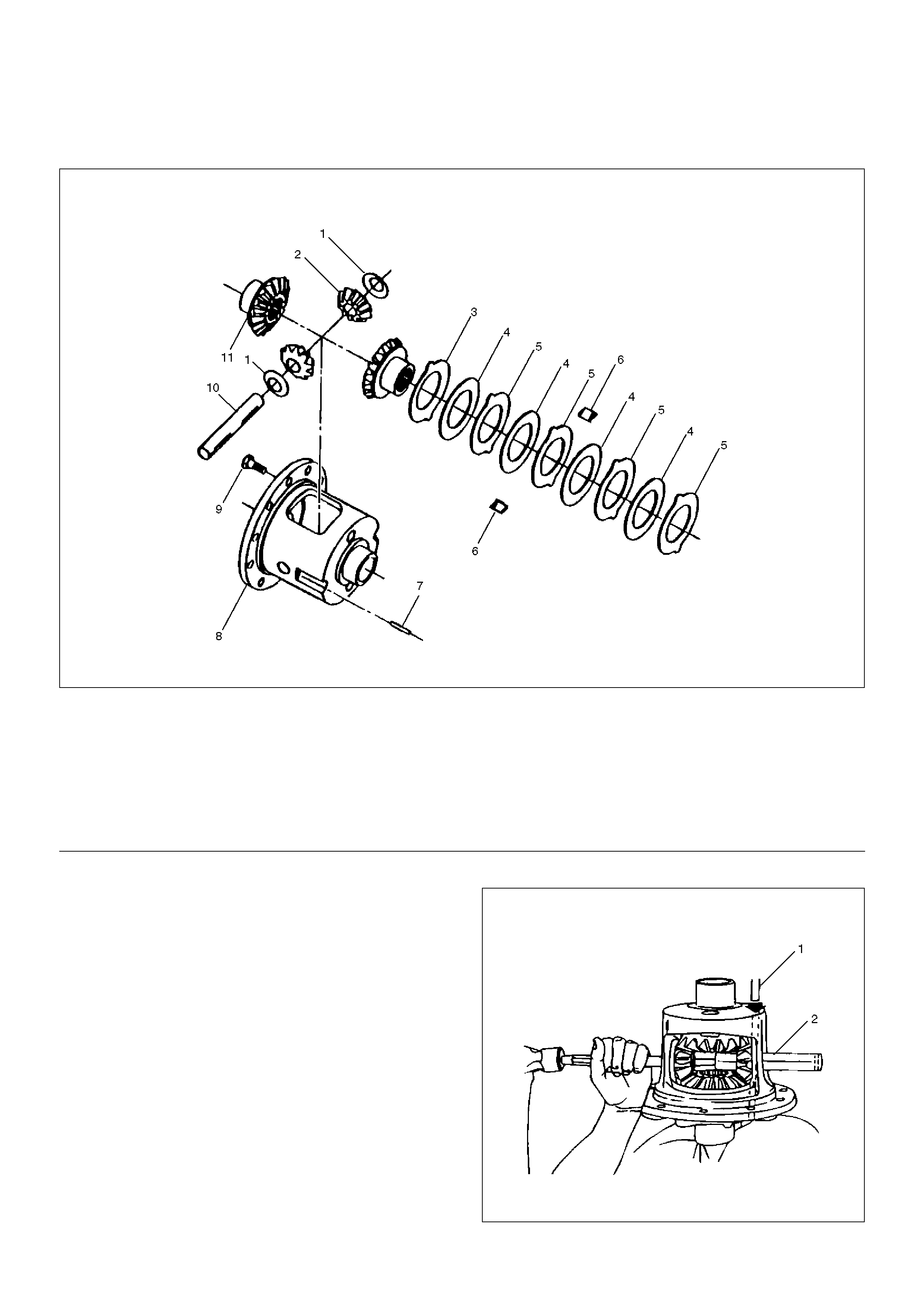
Limited Slip Differential Assembly
Disassembled View
425RW004
Legend
EndOFCallout
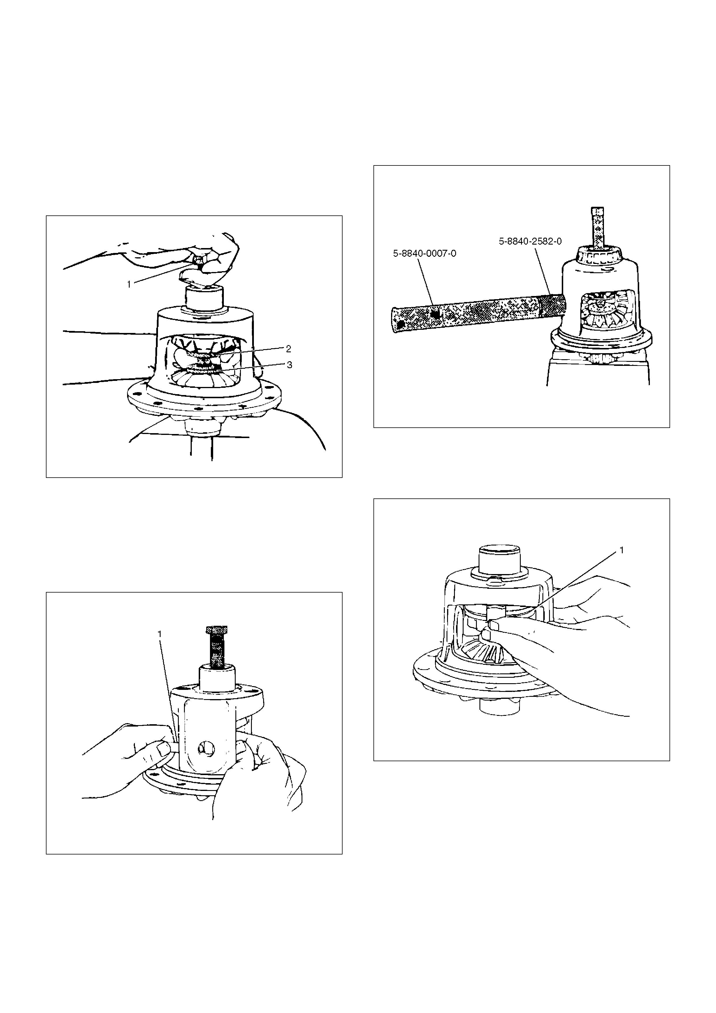
Disassembly
1. Place the holder 5–8840–2583–0 into a vise.
Position the differential on the holder with the ring
gear side down.
2. Remove Lock pin (1) from differential shaft using a
punch.
3. Remove Differential shaft (2) using hammer and
punch.
Place shop towel behind case to prevent differential
shaft from dropping out of case.
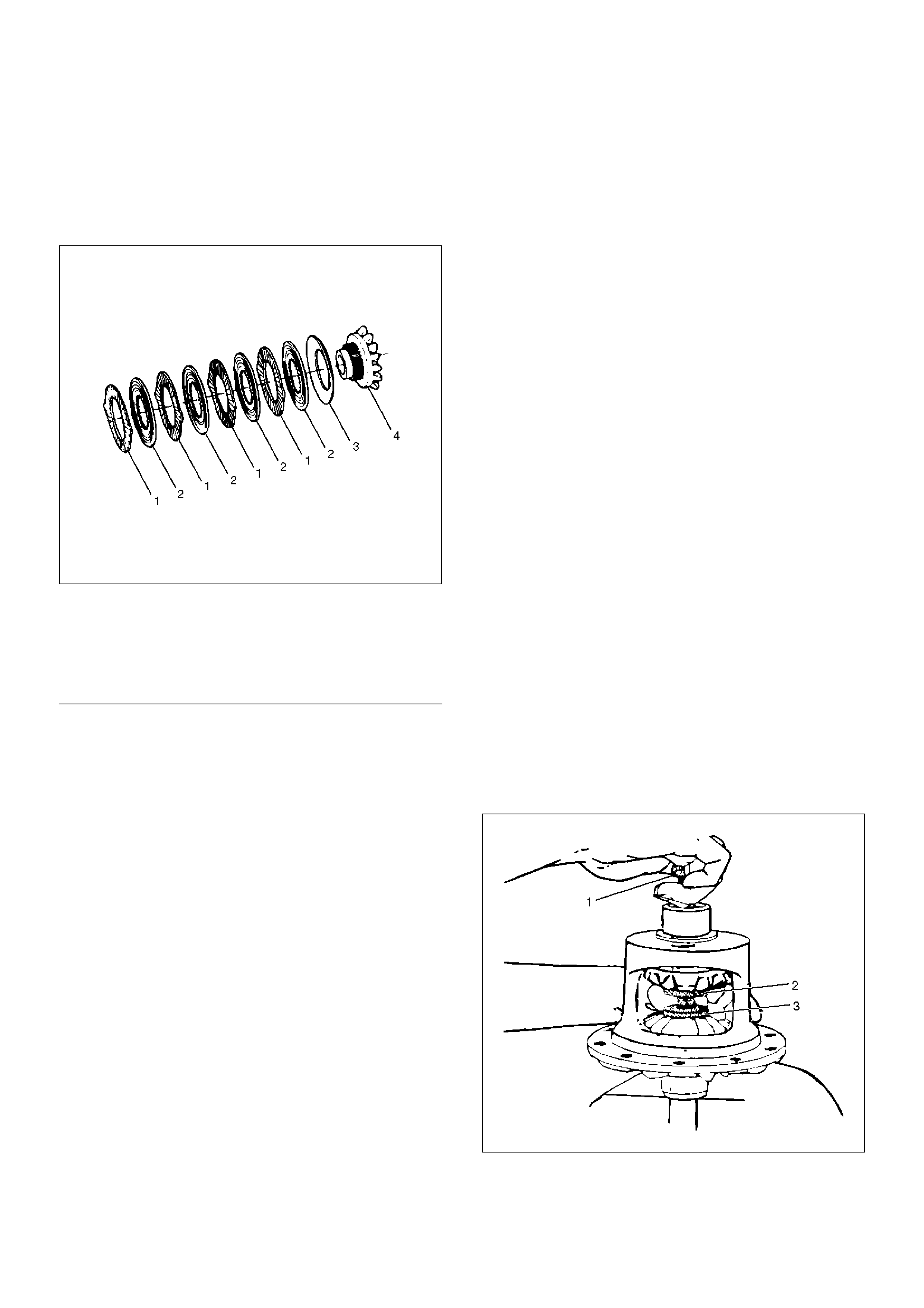
425RW005
(1) Thrust Washer–Differential Pinion Mate Gear
(2) Pinion Mate Gear
(3) Dished Spacer
(4) Disc
(5) Plate
(6) Differential Plate Retainer
(7) Lock Pin
(8) Differential Case
(9) Ring Gear Bolts
(10) Differential Shaft
(11) Differential Side Gear
4. Assemble clutch pack unloading tool 5–8840–2586–
0.
a Install cap(3) to the bottom differential side gear.
b Install threaded screw cap(2) to top differential
side gear. Thread forcing screws(1) into
threaded screw cap until it becomes centered
into the bottom cap.
901RW288
c Tighten forcing screw until tight enough to
collapse dished spacers and and allow
looseness between side and pinion mate gears.
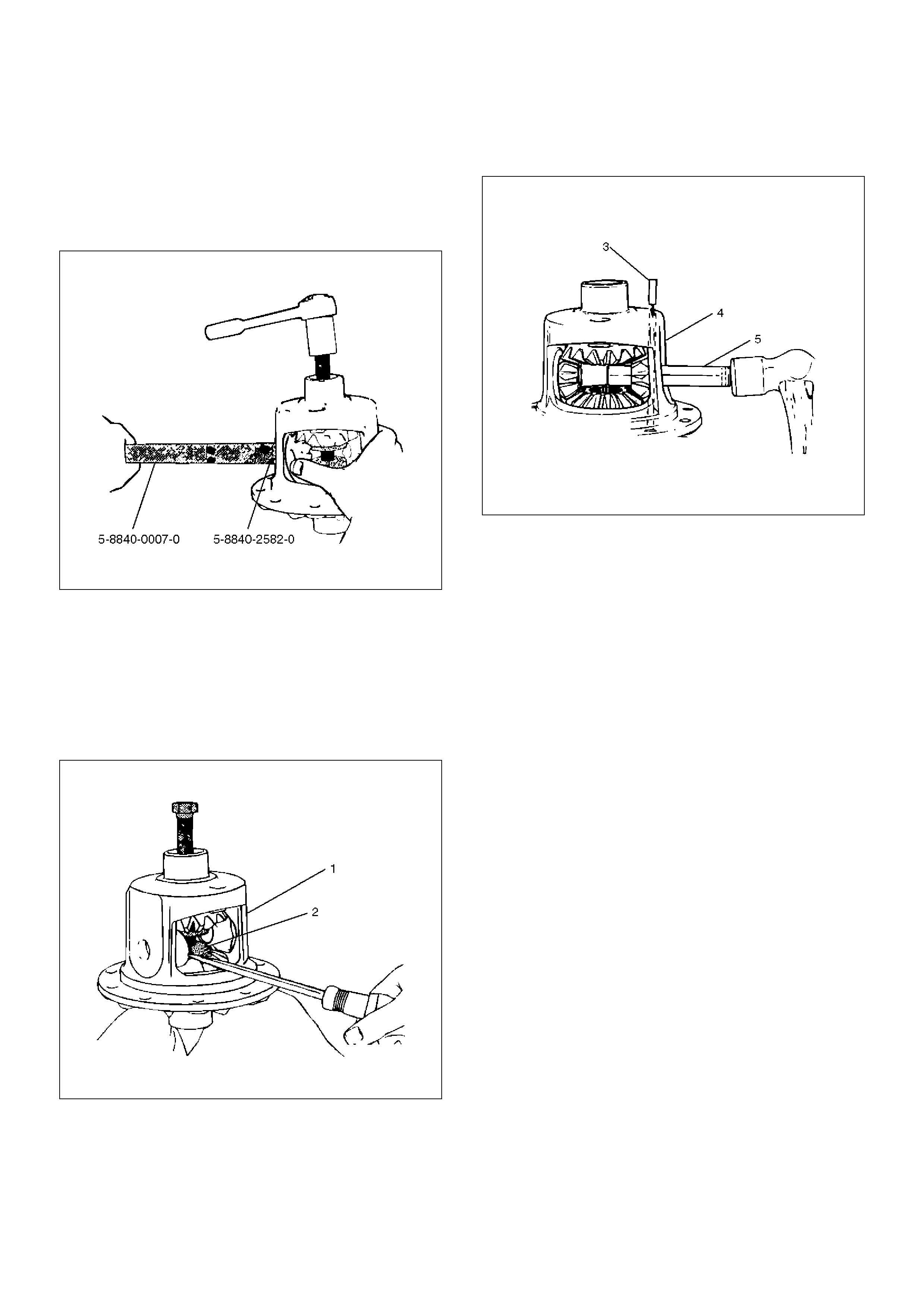
5. Both pinion mate gear thrust washers using a shim
stock (1) of 0.51 mm (0.020 in.) or equivalent tool to
push out washers.
425RW007
6. Relieve tension of dished spacers by loosening
forcing screw.
NOTE:
• You may have to adjust the forcing screw slightly to
allow the case to rotate.
7. Assemble LSD service adapter 5–8840–2582–0
onto long drive handle 5–8840–0007–0. Insert it into
differential shaft hole of case. Pull on handle and
rotate case until pinion mate gears can be removed.
901RW289
8. Remove pinion mate gears.
9. Hold side gear top clutch pack (1) with one hand
and remove positraction unloading tools.
425RW008
10. Remove top side gear and clutch pack.
NOTE:
• Keep the stack of plates and discs intact and in
exactly the same position while they are being
removed.
11. Remove case from holder. Turn case with flange or
ring gear side up to allow side gear and clutch pack
to be removed from case.
12. Remove differential plate retainer from both clutch
packs to allow separation of the plates and discs.
NOTE:
• Keep the discs and plates in the same order as they
were removed.
425RW009
Legend
EndOFCallout
Inspection and Repair
Cleaning
• All parts with solvent.
Visual Inspection
• Clean all parts with solvent.
• Plates and Discs. If any one disc or plate in either
stack shows evidence of excessive wear or scoring,
the complete stack is to be replaced on both sides.
• Side Gears and Pinion Mate Gears. The gear teeth of
these parts should be checked for extreme wear and
possible cracks. The external teeth of the side gear,
which retain the concentric groove discs, should also
be checked for wear or cracks.
• If replacement of one gear is required due to wear,
etc., then both side gears, pinion mate gears, and
thrust washers are to be replaced.
• Differential Shaft. If excessive wear is evident, the
differential shaft should be replaced.
• Differential Plate Retainers. If wear is evident on any
one of the differential plate retainers, all four
retainers must be replaced.
• Differential Case. If scoring, wear or metal pickup is
evident on the machined surfaces, replacement of
the case is necessary.
Reassembly
1. Lubricate thrust face of side gears, plates and discs
with the proper limited slip rear axle lubricant.
2. Assemble plates and discs in exactly in the same
position as they were removed, regardless of
whether they are new or original.
3. Install differential plate retainer to ears of plates.
NOTE:
• Make sure both retainers are completely seated on
ears of plates.
4. Install clutch pack and side gear into bottom side
gear bore. Make sure clutch pack stays assembled
to side gear splines, and that retainers are
completely seated into pockets of case.
NOTE:
• To prevent clutch pack from falling out of case, hold
clutch pack in place by hand while repositioning case
on bench.
5. Install other side gear and clutch pack. Make sure
clutch pack stays assembled to side gear splines,
and retainers are completely seated into pockets of
case.
6. Hold clutch pack in position and assemble screw
cap(2), cap(3) and forcing screw(1). Tighten forcing
screw into bottom cap to hold both clutch packs in
position.
7. With tools assembled to case, position case on
holder 5–8840–2583–0 by aligning splines of side
gear with those of shaft. Tighten forcing screw to
compress clutch packs in order to provide
clearance for pinion mate gears.
901RW288
8. Install pinion mate gears.
• Place the pinion mate gears into the differential
180 degrees apart.
(1) Differential Plate
(2) Differential Disc
(3) Dished Spacer
(4) Side Gear
9. While holding gears in place, insert LSD service
adapter 5–8840–2582–0 with long drive handle 5–
8840–0007–0 in differential shaft hole of case. Pull
on long drive handle and rotate case, allowing
gears to turn. Make sure that holes in pinion mate
gears align with holes in case.
901RW290
• It may be necessary to adjust tension on forcing
screw to rotate case.
10. Tighten forcing screw to compress the clutch packs,
to allow installation of spherical thrust washers.
11. Lubricate spherical thrust washers (2), and
assemble into case (1). Use a small screw driver to
push washers into place. Remove tools.
425RW012
12. Position differential shaft in case and drive in with
hammer. Be sure lock pin hole of differential shaft
(5) is properly aligned to allow installation of lock
pin (3). Be sure that thrust washers and differential
pinion mate gears are aligned with the differential
case (4). Install new lock pin to proper depth using a
punch.
Stake metal of case over pin in two places, 180
degrees apart.
425RW013
Main Data And Specifications
General Specifications
Rear axle
Type Salisbury, Semi–floating
Rear axle Size 226mm (8.9in)
Gear type Hypoid
Gear ratio (to 1) 4.100 (6VD1 with A/T)
4.300 (6VD1 with M/T)
Differential type Two pinion
Lubricant Grade GL–5: (Standard differential)
GL–5, LSD: (Limited slip differential)
Locking Differential Lubricant 80W90 GL–5
(USE Limited Slip Differential Gear Lubricant or Friction
Modifier Organic Additive)
Capacity 1.77 liter (1.87 US qt)
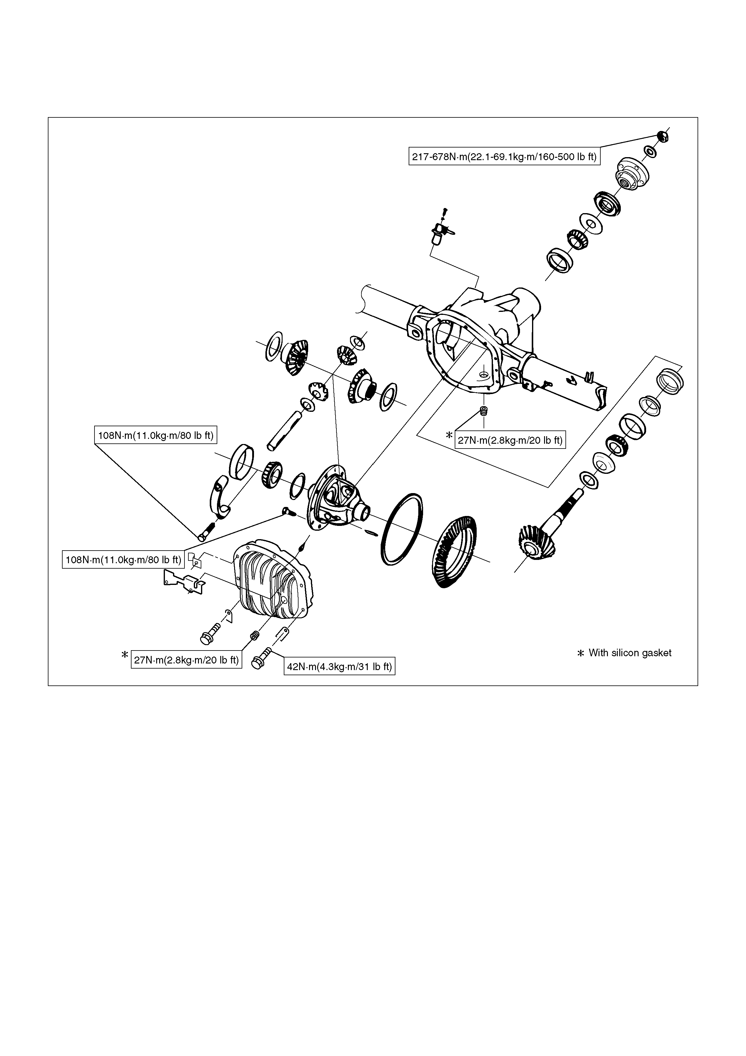
Torque Specifications
420R100002
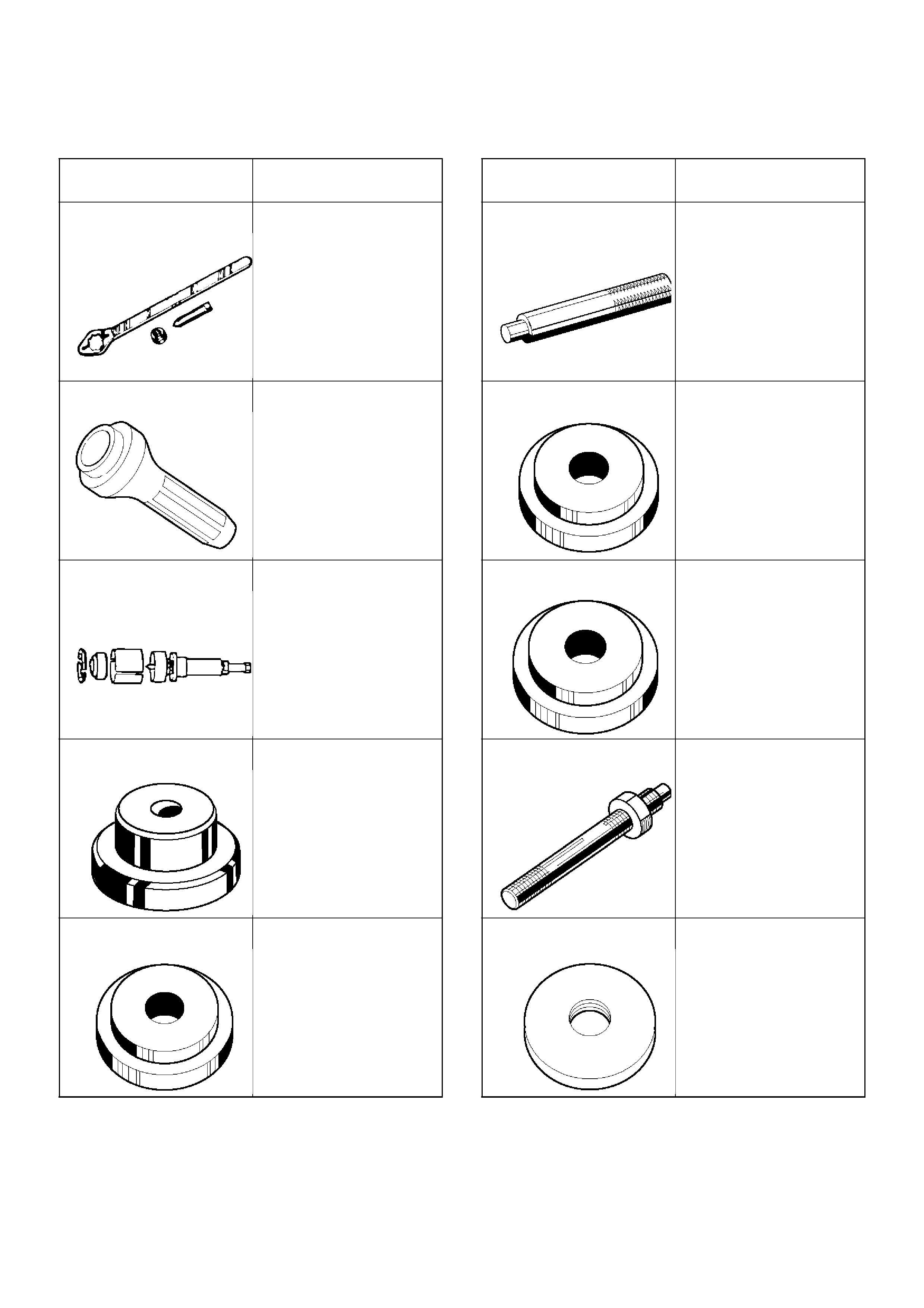
Special Tools
ILLUSTRATION TOOL NO.
TOOL NAME
5–8840–0133–0
(J–8614–01)
Pinion flange holder
5–8840–2165–0
(J–37263)
Installer; Pinion oil seal
5–8840–2587–0
(J–42379)
Remover; Bearing
5–8840–2585–0
(J–39830)
Adapter; Side bearing
plug
5–8840–0008–0
(J–8611–01)
Installer; Outer bearing
outer race
5–8840–0007–0
(J–8592)
Grip
5–8840–2569–0
(J–42836)
Installer; Inner bearing
outer race
5–8840–2575–0
(J–42824)
Pilot;Outer
5–8840–0127–0
(J–21777–43)
Nut & Stud
5–8840–2573–0
(J–42827)
Pilot;Inner
ILLUSTRATION TOOL NO.
TOOL NAME
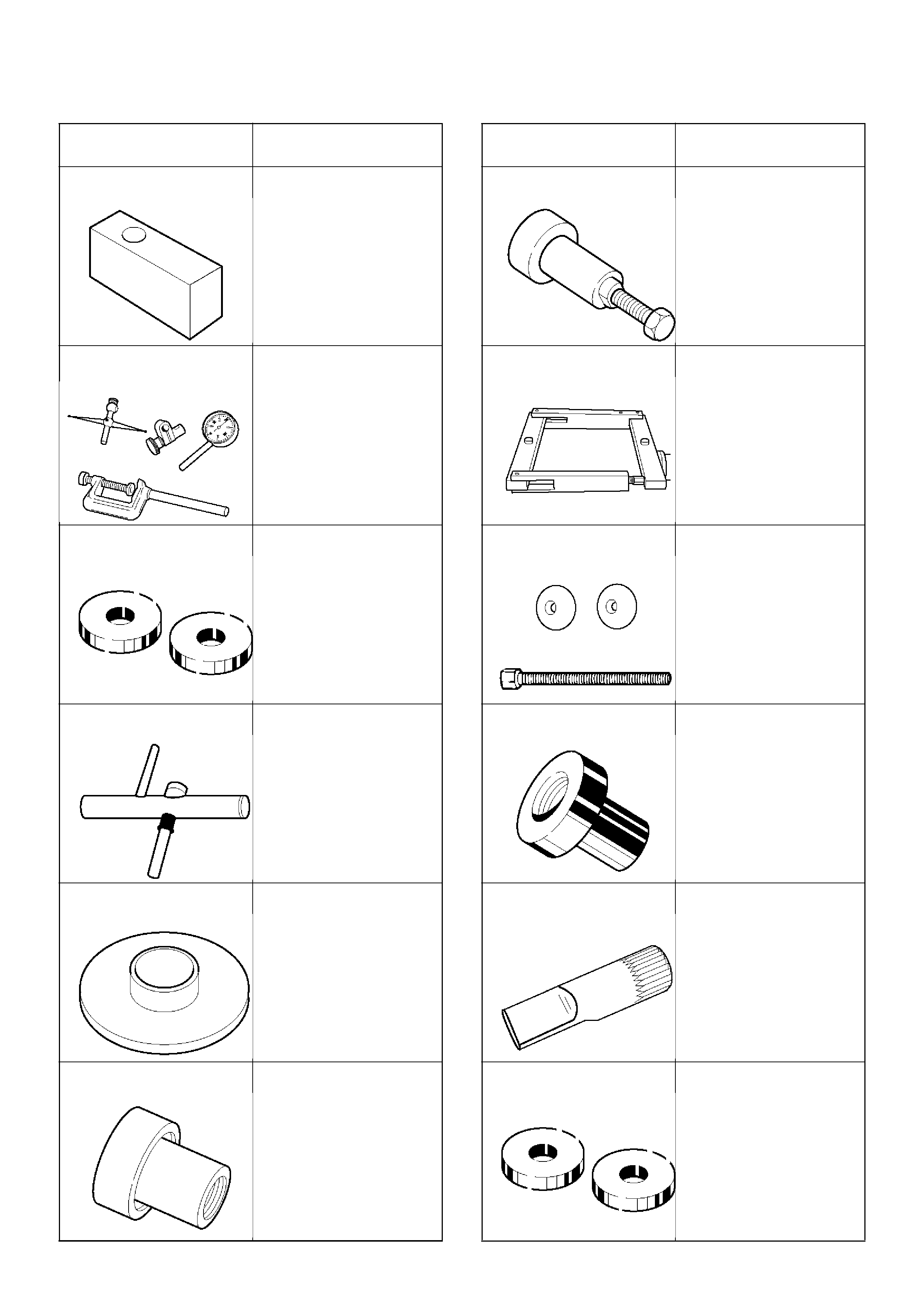
5–8840–2578–0
(J–39837–2)
Gauge plate
5–8840–0126–0
(J–8001)
Dial indicator
5–8840–2579–0
(J–39837–1)
Disc (2 required)
5–8840–0128–0
(J–23597–1)
Arbor
5–8840–2574–0
(J–42828)
Installer; Pinion bearing
5–8840–2580–0
(J–21784)
Installer; Side bearing
ILLUSTRATION TOOL NO.
TOOL NAME
5–8840–2323–0
(J–39602)
Remover; Outer bearing
5–8840–2581–0
(J–24385–B)
Spreader
5–8840–2586–0
(J–39858)
Clutch pack unloading
tool kit
5–8840–2582–0
(J–39834)
Limited–slip differential
(LSD) service adapter
5–8840–2583–0
(J–39824)
Holder
5–8840–2584–0
(J–39836)
Side bearing preload
master bearings
ILLUSTRATION TOOL NO.
TOOL NAME