
SECTION 5A - BRAKE CONTROL SYSTEM (MY2002)
Servic e Prec aut ion
General Description
Functional Description
System Components
Electronic Hydraulic Control Unit (EHCU)
ABS Warning Lamp
Wheel Speed Sensor
G-Sensor
Brake Pedal Travel
Acronyms and Abbreviations
General Diagnosis
General Information
ABS Service Precautio ns
Computer System Service Precautions
General Service Precautions
Note on Intermittents
“ABS" Warning Lamp
Test D riv ing ABS C omp la int Ve hicles
Tech 2 Scan Tool
Using TECH 2 On The Vehicle
Chassis Application Menu - Antilock Braking System
(ABS)
ABS TECH 2 Functions
Data List
Actuator Test
Procedure
Tech 2 Service Bleed
Basic Diagnostic Flow Chart
Basic Inspection Procedure
EHCU Connector Pin-out Checks
Circuit Diagram
Connector List
Part Location
Symptom Diag nos i s
Chart A-1 ABS Operates Frequently But The Vehicle
Does Not Decelerate
Chart TA-1 ABS Operates Frequently But The
Vehicle Does Not Decelerate (Use TECH 2)
Chart A-2 Uneven Braking Occurs While ABS
Operates
Char t TA-2 Uneven Braking Occurs While ABS
Operates (Use TECH 2)
Chart A-3, TA-3 The Wheels Are Locked During
Braking
Chart A-4 Abnormal Brake Pedal Feel
Chart A-5, TA-5 EHCU Is Heard Operating While Not
Braking
Diagnosti c Tro uble Codes
Diagnosis By “ABS" Warning Lamp Illumination Pattern
Chart B-1 Warning Lamp (W/L) is not activated when
the ignition is first turned ON .
Chart B-2 CPU Error (DTC C0271, C0272, C0273,
C0284)
Chart B-3 Low or High Ignition Voltage (DTC C0277,
0278 )
Chart B-4 Excessive Dump Time (DTC C0269)
Chart B-5 Excessive Isolation Time (DTC C0274)
Chart B-6 G-Sensor Output Failure (DTC C0276 )
Chart B-7 Brake Switch Failure (DTC C0281)
Chart B-8 4WD/TOD Control Unit Failure( DTC
C0285), 4WD State Input Signal Failure (DTC
C0282)
Chart B-9 Pump Motor Failure (DTC C0267, C0268)
Chart B-10 EHCU Valve Relay Failure (DTC C0265,
C0266 )
Chart B-11 FL Isolation Solenoid Coil Failure (DTC
41 C0245, C0247)
Chart B-12 FL Dump Solenoid Coil Failure (DTC
C0246, C0248)
Chart B-13 FR Isolation Solenoid Coil Failure (DTC
C0241, C0243 )
Chart B-14 FR Dump Solenoid Coil Failure (DTC
C0242, C0244)
Chart B-15 Rear Isolation Solenoid Coil Failure (DTC
C0251, C0253)
Chart B-16 Rear Dump Solenoid Coil Failure (DTC
C0252, C0254)
Chart B-17 FL Speed Sensor Open or Shorted (DTC
C0225)
Chart B-18 FR Speed Sensor Open or Shorted (DTC
C0221
Chart B-19 Rear Speed Sensor Open or Shorted
(DTC C0235)
Chart B-20 FL Speed Sensor Signal Missing (DTC
C0226, C0227)
Chart B-21 FR Speed Sensor Signal Missing (DTC
C0222, C0223)
Chart B-22 Rear Speed Sensor Signal Missing (DTC
C0236, C0237)
Chart B-23 Simultaneous Drop-out of Front Speed
Sensor Signal (DTC C0229)
Chart B-24 Abnormal Wheel Speed Input (DTC
C0238)
Chart B-25 Abnormal TOD Signal (DTC C0287)
Unit Inspection Procedure
Chart C-1-1 FL Sensor Output Inspection Procedure
Chart C-1-2 FR Sensor Output Inspection Procedure
Chart C-1-3 Rear Sensor Output Inspection
Procedure
Chart TC-1 Sensor Output Inspection Procedure
Special Tools

Service Precaution
WARNING: THIS VEHICLE HAS A SUPPLEMENTAL
RESTRAINT SYSTEM (SRS). REFER TO THE SRS
COMPONENT AND WIRING LOCATION VIEW IN
ORDER TO DETERMINE WHETHER YOU ARE
PERFORMING SERVICE ON OR NEAR THE SRS
COMPONENTS OR THE SRS WIRING. WHEN YOU
ARE PERFORMING SERVICE ON OR NEAR THE
SRS COMPONENTS OR THE SRS WIRING, REFER
TO THE SRS SERVICE INFORMATION. FAILURE TO
FOLLOW WARNINGS COULD RESULT IN POSSIBLE
AIR BAG DEPLOYMENT, PERSONAL INJURY, OR
OTHERWISE UNNEEDED SRS SYSTEM REPAIRS.
CAUTION: Always use the correct fastener in the
proper location. When you replace a fastener, use
ONLY the exact part number for that application.
HOLDEN will call out those fasteners that require a
replacement after removal. HOLDEN will also call
out the fasteners that require thread lockers or
thread sealant. UNLESS OTHERWISE SPECIFIED,
do not use supplemental coatings (Paints, greases,
or other corrosion inhibi tors) on threaded faste ners
or fastener joint interfaces. Generally, such
coatings adversely affect the fastener torque and
the joint clamping force, and may damage the
fastener. When you inst all fasteners, use the correct
tightening sequence and specifications. Following
these instructions can help you avoid damage to
parts and syst ems.
General De scription
The Anti-lock Brake System (ABS) works on all four
wheels. B y mon ito ring whe el sp eed s ens or s i gna ls , th e
Electronic Hydraulic Control Unit (EHCU) can determine
when a road wheel is about to lock and will adjust brake
pressure to maintain optimum braking under most
conditions. By optimisinjg the braking effort without
locking the wheels, the ABS enables the driver to
maintain control of the vehicle under heavy braking
conditions.
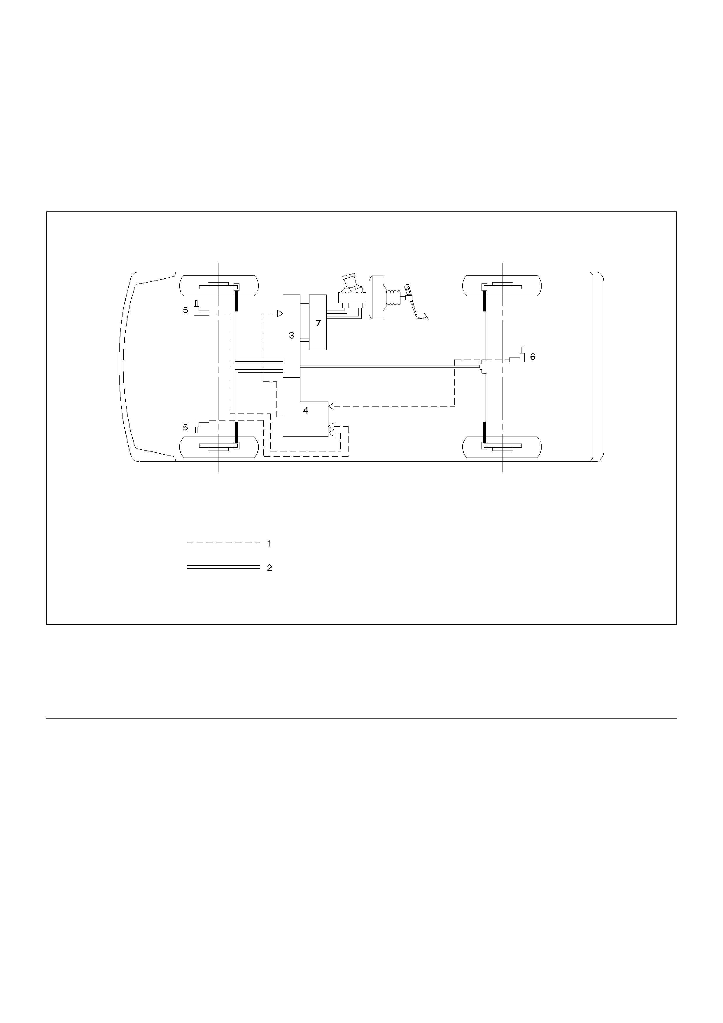
NOTE: The Electronic Hydraulic Control Unit (EHCU)
comprises the Hydraulic Unit (H/U) and the coil
Integrated Module.
C05RW004
Legend
EndOFCallout
(1) Electronic
(2) Hydraulic
(3) Hydraulic Unit (H/U)
(4) Coil Integrated Module
(5) Front Wheel Speed Sensor
(6) Rear Wheel Speed Sensor
(7) Proporti oni ng and By pass (P&B) Valve
Functional Description
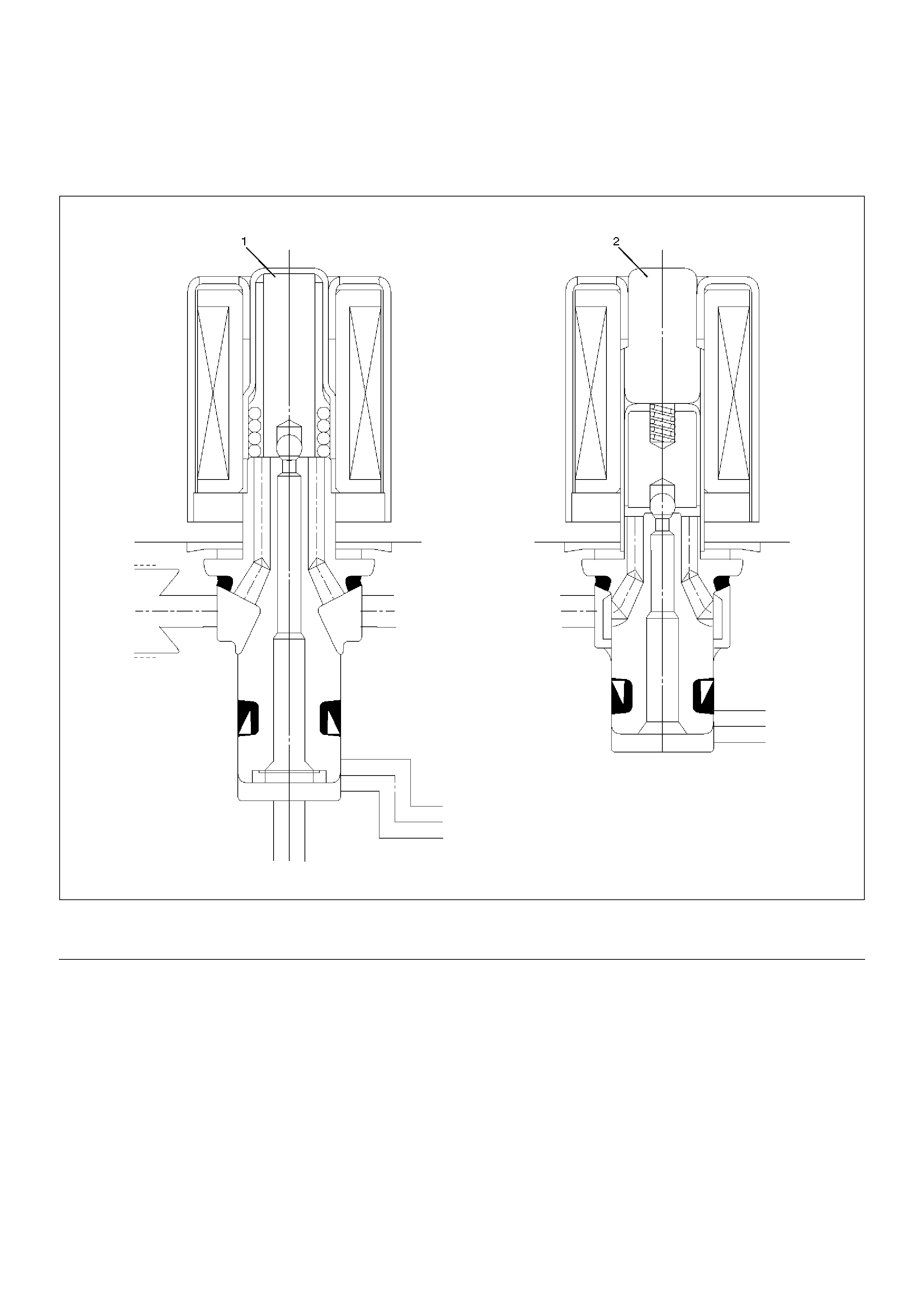
Hydraulic Unit (H/U)
Solenoid Valve
C05RW012
Legend
EndOFCallout
(1) Isolation Valve (2) Dump valve
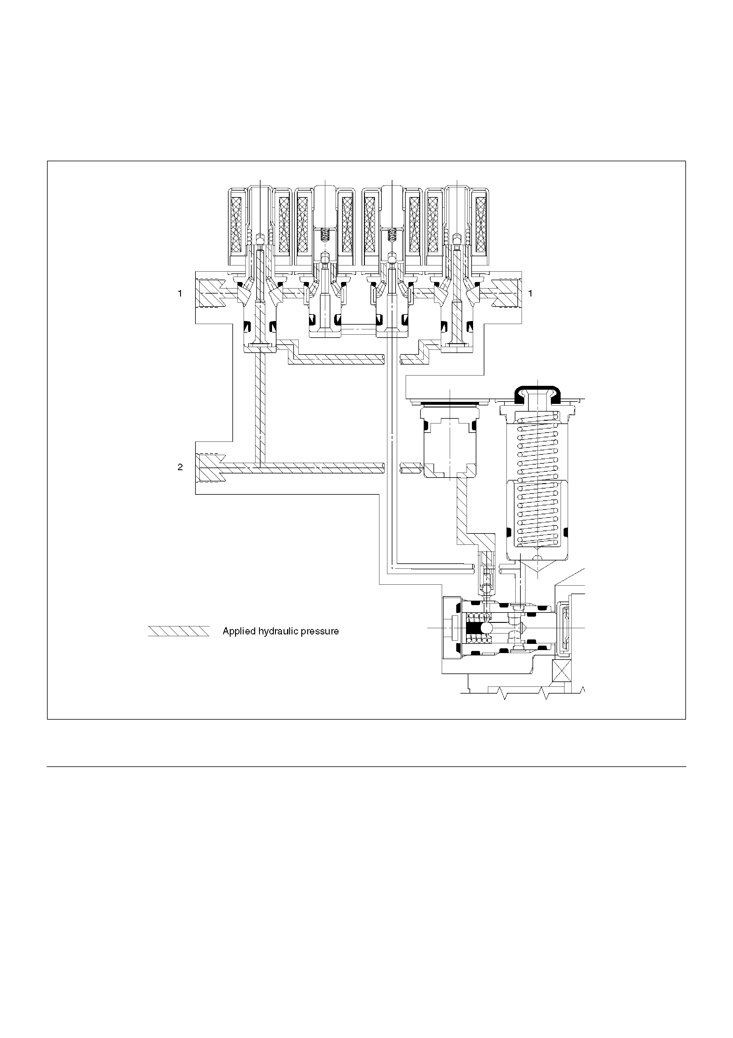
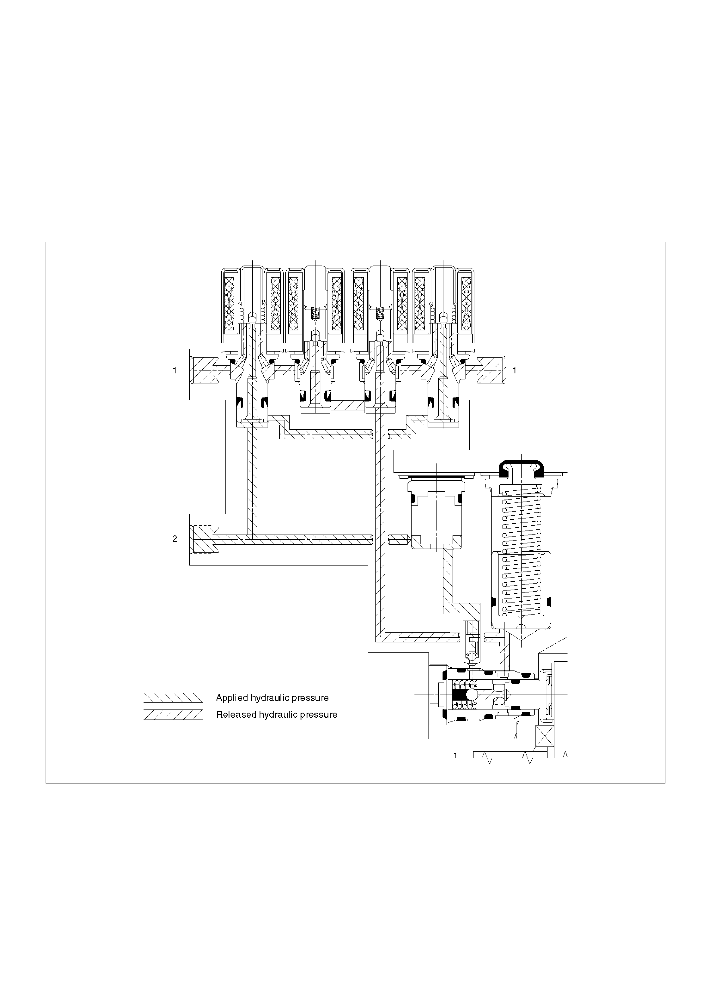
Normal Braking
During normal (non anti-lock) braking, the solenoid
valves are without current and closed due to spring
force.
Brake fluid travels through the centre of the normally
open isolation valve around the normally closed dump
valve and on to the brake pistons.
C05RW010
Legend
EndOFCallout
(1) Brake (2) Master Cylinder
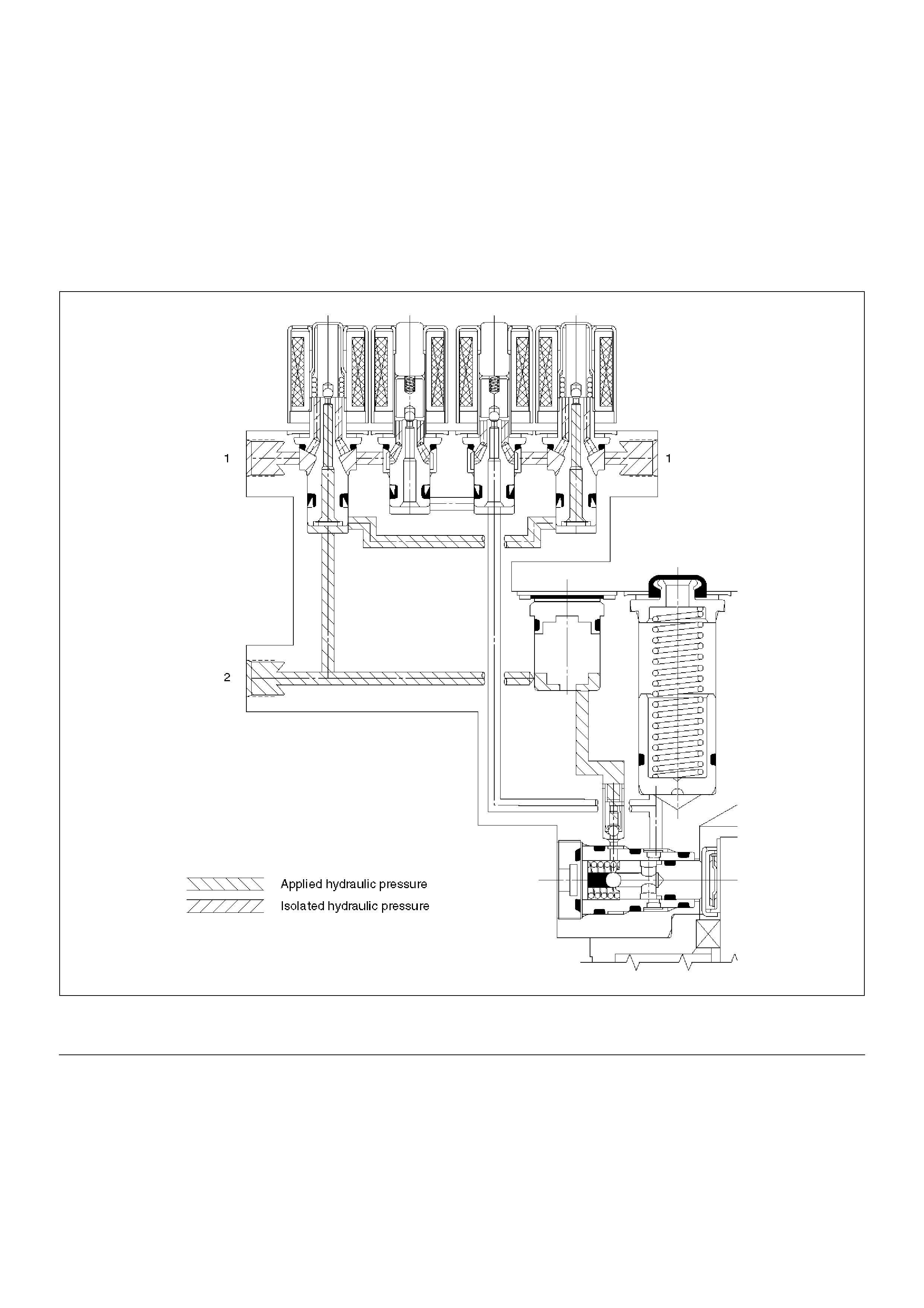
Pressure Isolation (Pressure Maintain)
The electro-hydraulic control unit is activated when the
brakes are applied which sends a signal to the coil
integrated module to prepare for a possible anti-lock
stop.
If the information from the wheel speed sensors
indicates excessive wheel deceleration (imminent
lockup), the first step in the anti-lock sequence is to
isolate the brake pressure being applied by the brake
pedal.
The microprocessor in the coil integrated module sends
a voltage to the coil to energize and close the isolation
valve. This prevents any additional fluid pressure
applied by the brake pedal from reaching the wheel.
With the isolation valves closed, further unnecessary
increase in the brake pressure is therefore prevented.
C05RW011
Legend
EndOFCallout
(1) Brake (2) Master Cylinder
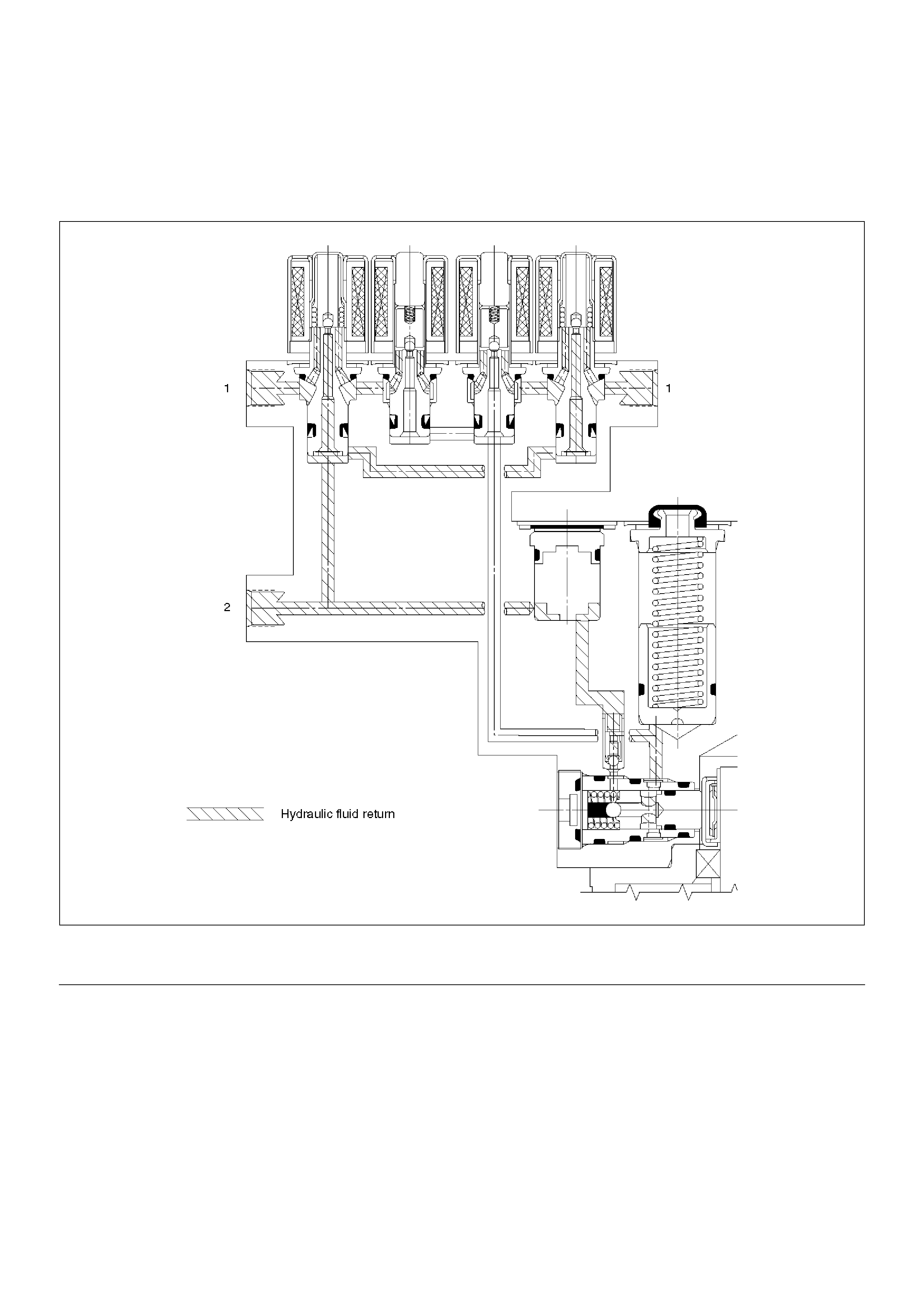
Pressure Reduction
Once the brake pressure is isolated, it must be reduced
to allow the wheels to unlock. This is accomplished by
dumping a portion of the brake fluid pressure into a low
pressure accumulator.
The microprocessor activates the normally closed dump
valve to open, allowing fluid from the wheels to be
dumped into the accumulator. This is done with very
short activation pulses opening and closing the dump
valve passageway. Brake pressure is reduced at the
wheel and allows the wheel to begin rotating again. The
fluid from the brake piston is stored in the accumulator
against spring pressure and a portion of this fluid also
primes the pump.
The dump valves are operated independently to control
the deceleration of the wheel. At this point, the brake
pedal is isolated from the base brake system, the
hydraulic control unit pumps are primed and the
attenuators are ready to pump fluid.
C05RW009
Legend
EndOFCallout
(1) Brake (2) Master Cylinder

Pressure Increase (Re-apply)
The re-apply sequence is initiated to achieve optimum
braking. The isolation valve is momentarily opened to
allow master cylinder and pump pressure to reach the
brakes. This controlled pressure rise continues until the
wheel is at optimum brake output or until the brake
pressure is brought up to the master cylinder output
pressure.
If more pressure is required, more fluid is drawn from
the master cylinder and applied to the brakes. The
driver may feel slight pedal pulsations, or pedal drop,
this is normal and expected.
As fluid is re-applied to the brakes, the wheel speed will
reduce. If the wheels approach imminent lockup again,
the module will isolate, dump and re-apply again. This
cycle occurs in millisecond intervals, allowing several
cycles to occur each second. It is a much faster and
more controlled way of “pumping the pedal".
C05RW014
Legend
EndOFCallout
(1) Brake (2) Master Cylinder
Brake Release
At the end of the anti-lock stop, when the brake pedal is
released, the pump will remain running for a short time
to help drain any fluid from the accumulators. As this
fluid returns into the system, the spring forces the piston
back to its original position.
The isolation valve opens and fluid may return to the
master cylinder. Conventional braking is then resumed.
C05RW013
Legend
EndOFCallout
(1) Brake (2) Master Cylinder
System Components
Electronic Hydraulic Control Unit (EHCU), three Wheel
Speed Sensors, Warning Lamp, and G-sensor.
Electronic Hydraulic Control Unit (EHCU)
The EHCU consists of ABS control circuits, fault
detector, and a fail-safe. It drives the hydraulic unit
according to the signal from each sensor, cancelling
ABS to return to normal braking when a malfunction has
occurred in the ABS.
The EHCU has a self-diagnosing function which can
indicate faulty circuits during diagnosis.
The EHCU is mounted on the engine compartment rear
right side. It consists of a Motor, Plunger Pump,
Solenoid Valves.
Solenoid Valves: Reduces or holds the caliper fluid
pressure for each front disc brake or both rear disc
brakes according to the signal sent from the EHCU.
Rese rv oir: Tempor arily ho l ds t he b r a ke fluid th at re t ur ns
from the front and rear disc brake caliper so that
pressure of front disc brake caliper can be reduced
smoothly.
Plunger Pump: Feeds the brake fluid held in the
reservoir to the master cylinder.
Motor: Drives the pump according to the signal from
EHCU.
Check Valve: Controls the brake fluid flow.
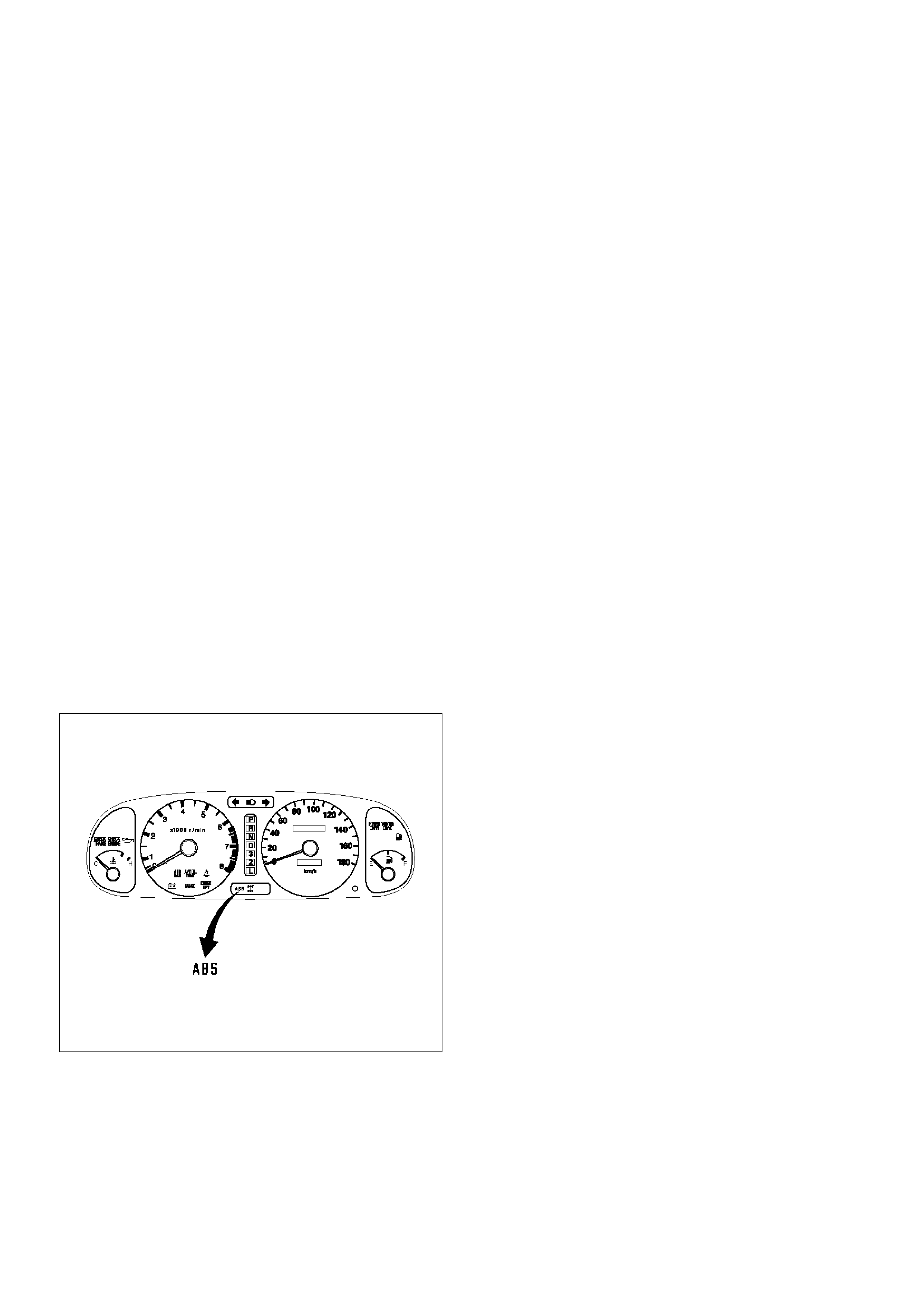
ABS Warning Lamp
825RX048
Vehicles equipped with the Anti-lock Brake System
have an amber “ABS" warning lamp in the instrument
panel. The “ABS" warning lamp will illuminate if a
malfunction in the Anti-lock Brake System is detected
by the Electronic Hydraulic Control Unit (EHCU). In
case of an electronic malfunction, the EHCU will turn
“ON" the “ABS" warning lamp and disable the Anti-lock
braking function.
The “ABS" lamp will turn “ON" for approximately three
seconds after the ignition switch is to the “ON" position.
If the “ABS" lamp stays “ON" after the ignition switch is
the “ON" position, or comes “ON" and stays “ON" while
drivi ng, the Anti-lock Brake System should be inspected
for a malfunction according to the diagnosis procedure.
Wheel Speed Sensor
It consists of a sensor and a rotor. The sensor is
attached to the knuckle on the front wheels and to the
rear axle case on the rear differential.
The rotor is press-fit in the axle shaft.
The flux generated from electrodes magnetized by a
magnet in the sensor varies due to rotation of the rotor ,
and the electromagnetic induction generates alternating
voltage in the coil. This voltage draws a “sine curve"
with the frequency proportional to rotor speed and it
allows detection of wheel speed.
G-Sensor
The G-sensor installed inside the EHCU detects the
vehicle deceleration speed and sends a signal to the
EHCU. In 4WD operation, all four wheels may be
decelerated in almost the same phase, since all wheels
are connected mechanically.
This tendency is noticeable particularly on roads with
low friction coefficient, and the ABS control is adversely
affected.
The G-sensor judges whether the friction coefficient of
road surface is low or high, and changes the EHCU's
operating system to ensure ABS control.
Normal and Anti-lock Braking
Under normal driving conditions, the Anti-lock Brake
System functions the same as a standard power
assisted brake system. However, with the detection of
wheel lock-up, a slight bump or kick-back will be felt in
the brake pedal. This pedal “bump" will be followed by a
series of short pedal pulsations which occurs in rapid
succession. The brake pedal pulsation will continue
until there is no longer a need for the anti-lock function
or until the vehicle is stopped. A slight ticking or popping
noise may be heard during brake applications when the
Anti-lock features is being used.
When the Anti-lock feature is being used, the brake
pedal may rise even as the brakes are being applied.
This is also normal. Maintaining a constant force on the
pedal will provide the shortest stopping distance.
Br ake Pedal Travel
Vehicles equipped with the Anti-lock Brake System may
be stopped by applying normal force to the brake
pedal. Although there is no need to push the pedal
beyond the point where it stops or holds the vehicle, by
applying more force the pedal will continue to travel
toward the floo r.
This extra brake pedal travel is normal.

Acronyms and Abbreviations
Several acronyms and abbreviations are commonly
used throughout this section:
ABS
Anti-lock Brake System
CIM
Coil Integrated Module
CKT
Circuit
DLC
Data Link Connect or
EHCU
Electronic Hydraulic Control Unit
FL
Front Left
FR
Front Right
GEN
Generator
H/U
Hydraulic Unit
MV
Millivolts
RR
Rear
RPS
Revolution per Second
VDC
DC Volts
VAC
AC Volts
W/L
Warning Lamp
WSS
Wheel Speed Sensor
General Diagnosis
General Information
ABS troubles can be classified into two types, those
which can be detected by the ABS warning lamp and
those which can be detected as a vehicle abnormality
by the driver.
In either case, locate the fault in accordance with the
“Basic Diagnostic Flowchart" and repair.
Please refer to Section 5C for the diagnosis of
mechanical troubles such as brake noise, brake judder
(brake pedal or vehicle vibration felt when braking),
uneven braking, and parking brake trouble.
ABS Service Precautions
Required Tools and Items:
•Box Wrench
•Brake Fluid
• Special Tool
Some diagnosis procedures in this section require the
installation of a special tool.
5-8840-0366-0 High Impedance Multimeter
When circuit measurements are requested, use a circuit
tester with high impedance.
Computer System Service Precautions
The Anti-lock Brake System interfaces directly with the
Electronic Hydraulic Control Unit (EHCU) which is a
control computer that is similar in some regards to the
Powertrain Control Module. These modules are
designed to withstand normal current draws associated
with vehicle operation. However, care must be taken to
avoid overloading any of the EHCU circuits. In testing
for opens or shorts, do not ground or apply voltage to
any of the circuits unless instructed to do so by the
appropriate diagnostic procedure. These circuits should
only be tested with a high impedance multimeter
5-8840-0366-0 or special tools as described in this
section. Power should never be removed or applied to
any control module with the ignition in the “ON" position.
Before removing or connecting battery cables, fuses or
connectors, always turn the ignition switch to the “OFF"
position.
General Service Preca utions
The following are general precautions which should be
observed when servicing and diagnosing the Anti-lock
Brake System and/or other vehicle systems. Failure to
observe these precautions may result in Anti-lock
Brake System damage.
• If welding work is to be performed on the vehicle
using an electric arc welder, the EHCU and valve
block connectors should be disconnected before the
welding operation begins.
• The EHCU and valve block connectors should never
be connected or disconnected with the ignition “ON" .
• If only rear wheels are rotated using jacks or drum
tester, the system will diagnose a speed sensor
malfunction and the “ABS" warning lamp will
illuminate. But actually no trouble exists. After
inspection stop the engine once and re-start it, then
make sure that the “ABS" warning lamp does not
illuminate.
If the battery has been discharged
The engine may stall if the battery has been completely
discharged and the engine is started via jumper cables.
This is because the Anti-lock Brake System (ABS) self-
test places a high load on the electrical system. In this
case, wait until the battery is recharged, or set the ABS

to a non-operative state by removing the ABS (60A)
fuse. After the battery has been recharged, stop the
engine and reinstall the ABS fuse. Start the engine
again, and confirm that the ABS warning lamp does not
illuminate after the initial self-test has been conducted.
Note on Intermittents
As with virtually any electronic system, it is difficult to
identify an intermittent failure. In such a case duplicating
the system malfunction during a test drive or a good
description of vehicle behavior from the customer may
be helpful in locating a “most likely" failed component or
circuit. The symptom diagnosis chart may also be useful
in isolating the failure. Most intermittent problems are
caused by faulty electrical connections or wiring. When
an intermittent failure is encountered, check suspect
circuits for:
• Suspected harness damage.
• Poor mating of connector halves or terminals not fully
seated in the connector body (backed out).
• Improperly formed or damaged terminals.
“ABS" Warning Lamp
Normal Operation:
The “ABS” warning lamp will illuminate for about three
seconds when the ignition is first turned ON, while the
system performs a self-test.
Upon satisfactory completion of the self-test, the “ABS”
warning lamp will be extinguished. The “ABS” warning
lamp sho uld rema in “O FF " at all othe r tim es .
Fault Detected:
Should a fault be detected during the self-test, or an
ABS failure occur whilst driving, the EHCU will
illuminate the “ABS" warning lamp and log the
appropriate Diagnostic Trouble Code (DTC).
While the “ABS” lamp is illuminated, the anti-lock
braking syatem is disabled, although power assisted
braking is still available.
Should, on the next ignition cycle, the EHCU determine
the fault is no longer present, the “ABS” warning lamp
will extinguish after the self-test, but the DTC will remain
in the EHCU memory until cleared by Tech 2.
Test Driving ABS Complaint Ve hicle s
In case that there has been an abnormality in the
lighting pattern of “ABS" warning lamp, the fault can be
located in accordance with the “Diagnosis By “ABS"
Warning Lamp Illumination Pattern". It is necessary to
drive the vehicle following the test procedure mentioned
below inorder to reproduce the symptom for trouble
diagnosis:
1. Start the engine and make sure that the “ABS"
warning lamp goes OFF. If the warnng lamp
remains ON, it means that the Diagnostic Trouble
Code (DTC) is stored. Therefore, read the code
and locate the fault.
NOTE:After initiating the DTC clearing procedure with
Tech 2, the vehicle MUST be driven above 12 km/h to
finally clear the DTC and extinguish the ”ABS”
warning lamp.
2. Start the vehicle and accelerate to about 30 km/h.
3. Slowly brake and stop the vehicle completely.
4. Then restart the vehicle and accelerate to about 40
km/h.
5. Brake with sufficient pedal force so as to actuate the
ABS and stop the vehicle.
6. Be cautious of any abnormality during the road test.
If the warning lamp is actuated while driving, read
the DTC and locate the fault.
7. If the abnormality is not reproduced by the test,
endeavour to reproduce the situation reported by
the customer.
8. If the abnormality has been detected, carry out
repairs in accordance with the “Symptom Diagnosis"
.
NOTE:
• Be sure to perform the test drive on a wide, even road
with little or no other traffic.
• If any abnormality is detected, immediately suspend
the road test and commence fault diagnosis as soon
as practicable.
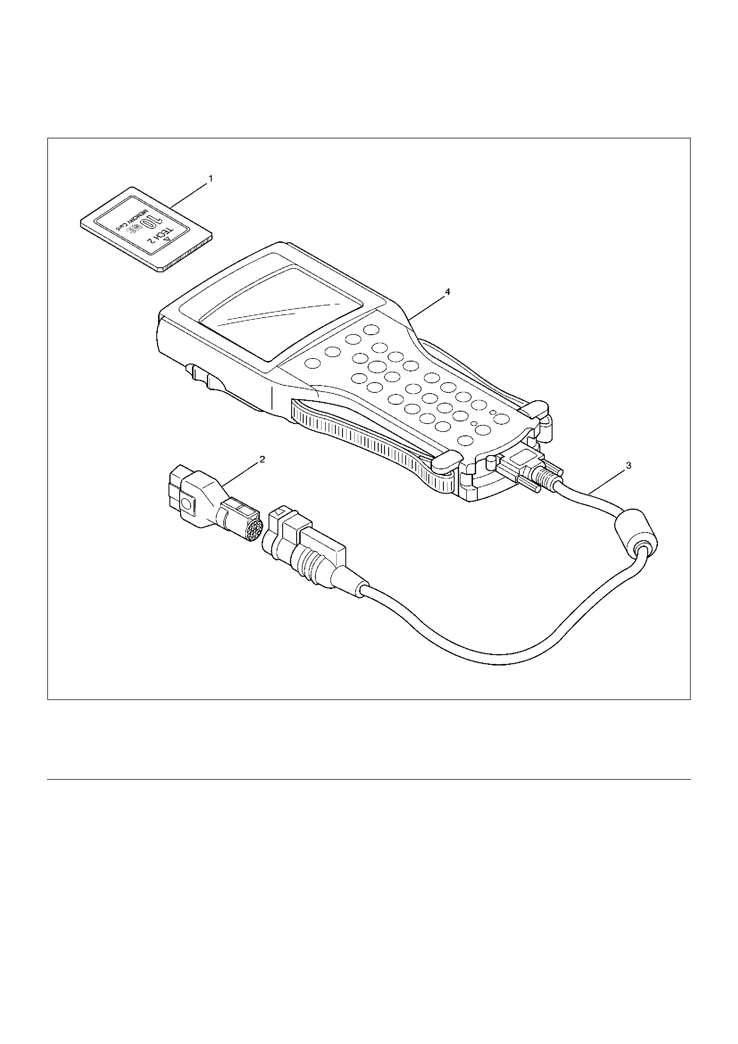
Tech 2 Scan Tool
901RW257
Legend
EndOFCallout
(1) PCMCIA Card
(2) SAE 16/19 Adaptor
(3) DLC Cable
(4) Tech–2

Using TECH 2 On The Vehicle
NOTE: Due to the constant evolution of TECH 2
software, the screens shown in this section may
differ slightly from those displayed for the vehicle
being tested.
Connecting TECH 2 To The Vehicle
1. Connect Tech 2 to the vehicle DLC, with the DLC
cable and the 16/19 pin adapter.
2. Switch the unit on by pressing the power button (2).
A green li ght (1) shoul d come on indi cating that th e
tool is receiving power.
NOTE: At this time the technician should see the Power
On Self Test (POST) run. The POST is a built in
diagnostic self test for the TECH 2 that should find most
common system faults. The POST is run on every
power up to ensure the best operation of the tool. After
the compl etion of the POST, th e TECH 2 uni t will briefly
show the POST results. If POST passes, the tool will
continue onto the title screen. If POST fails, results of all
tests will be d isplayed, an d this should sh ow which test
failed. POST failures may be classified as fatal or non-
fatal. A fatal error will not allow the user to continue
using the tool. Failure of the keypad would be an
example of a fatal error. Non-fatal errors found during
the POST will allow continued use of the TECH 2, but
with some limitations. If either a fatal or non-fatal error
occurs, refer to the Troubleshooting section of the
TECH 2 User's Guide.
1. Power Status Indicator Light
2. PWR (Power) Key
3. SHIFT Key Status Indicator Light
4. SHIFT Key
3. At the Tech 2 title screen press the ENTER key to
continue.

4. A selection can be made from the Main Menu,
either by usi ng a fu nction k ey o r by us ing the arrow
keys to highlight a menu choice and pressing
ENTER.
•NOTE: You will then need to supply some additional
information to the TECH 2. This requires navigation
through a series of lists (called picklists). On some
menus or pi ckl ists, the u se r can us e a fu nc tio n ke y t o
make a menu selection, but most of the picklists
require using the selection and action keys. If a
mistake is made in the selection process, or if a
different application or function is desired, press EXIT
to back up one level. Within an application, there may
be soft keys which are available for use. These soft
keys all ow access to a dditional to ol functi ons without
exitin g a curr ent tool fun ction . Soft keys a re made u p
of sets which will appear together . To see the next set
of soft keys, select the More soft key.
The TECH 2 Main Menu contains the following:
F0: Diagnostics
Contains all functions to test, diagnose, monitor and
program the different vehicle systems.
F1: Service Programming System (SPS)
SPS is used in conjunction with Technical
Information System (TIS) 2000 to program vehicle
control units.
F2: View Capture Data
Contains all functions to work with one or two
previously recorded snapshots on one or two
vehicles. This function is to enable the viewing of
captur ed data without a vehicl e.
F3: Tool Options
Contains the TECH 2 self test, set clock, set units,
set screen contrast and Getting Started.
F4: Download/Upload Help
Contains help information on the downloading and
uploading from the TECH 2 to the TIS 2000 CD-
ROM.
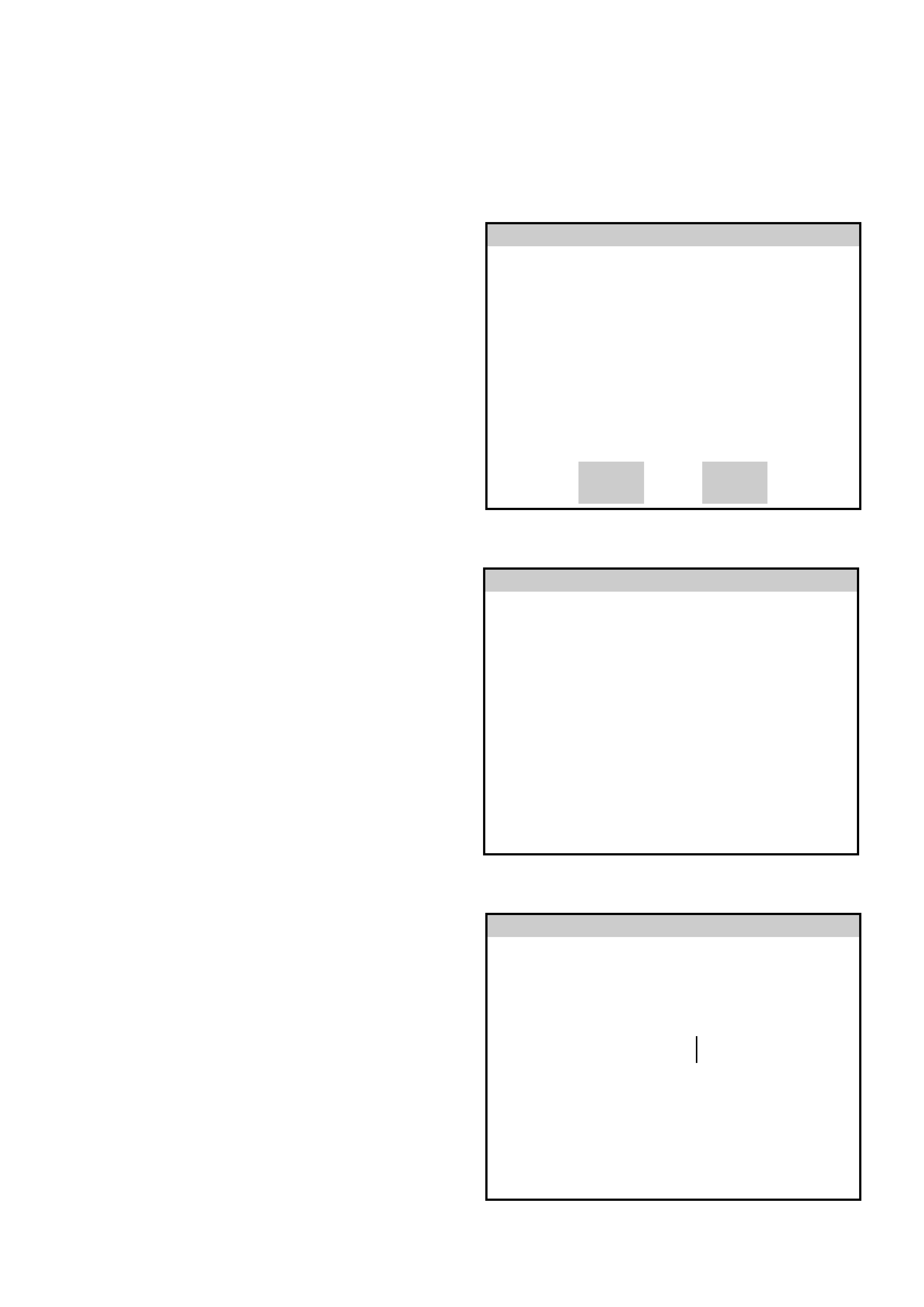
Main Menu
UES2002b
F0: Diagnostics
F1: Service Programming System (SPS)
F2: View Capture Data
F3: Tool Options
F4: Download/Upload Help
5. Select the correct Model Year with the arrow keys
and the press ENTER. The Vehicle identification
screen will then be displayed.
6. Select the correct Vehicle Type with the arrow keys
and the press ENTER. The System Select Menu
will then be displayed.
7. The desired system can be selected from the
System Se lect Menu wi th th e fu nc tio n key s or wit h
arrow keys and then press ENTER.
F0:Powertrain contains all functions to test,
diagnose , and monitor the engine and trans mission
systems that communicate with the Tech 2 via the
Powertrain Control Mod ule (PCM).
F1: Chassis contains all functions to test,
diagnose, monitor the vehicles chassis systems;
TOD and ABS modules.
F2: Body contains all functions to test, diagnose,
monitor the instruments and Supplemental
Restr a int Sy st em.
Main Menu
Select one of the following
Model Year(s)
TF2001a
(2)
(1)
(Y)
(X)
(W)
(V)
(2)
2002
2001
2000
1999
1998
1997
1 / 6
2002
Main Menu
Select one of the following
Vehicle Type(s)
Frontera
Jackaroo
Rodeo
VX Commodore
VU Utility
WH Statesman & Caprice
V2 Monaro
Corsa-C
Astra-F
Astra-G
Frontera 1 / 10
UES2002c
System Select Menu
(2) 2002 Frontera
F0: Powertrain
F1: Chassis
F2: Body
UES2002abs3
Chassis Application Menu - Antilock Braking System (ABS)
1. Select the correct chassis system from the Vehicle
Identification menu with the arrow keys, then
press ENTER and follow the instructions on the
screen.
2. Turn on the ignition and press the Confirm soft key.
3. The System identification screen will t hen displ ay
the control module Part number and System type.
Press the Confirm soft key, and the ABS application
menu will then be displayed.
The following functions are available in the ABS chassis
application menu:
F0: Diagno stic Trouble Codes
F1: Data Display
F2: Snapshot
F3: Actuators
F4: Miscellaneous Tests
System Select Menu
(2) 2002 Frontera
F0: ABS
F1: TOD
UES2002abs4
System Identification
(2) 2002 Frontera
Electronic System: ABS
UE2002abs1
Part number
System 8972874320
ABS
Confirm
Chassis
F0: Diagnostic Trouble Codes
F1: Data Display
F2: Snapshot
F3: Actuator Tests
F4: Miscellaneous Tests
UES2002abs5

ABS TECH 2 Functions
F0: DIAGNOSTIC TROUBLE CODES
In this test mode, DTC(s) stored by the ABS Module can be displayed or cleared. When F0: Diagnostic Trouble Codes
is selected, there are an additional three modes:
F0: Read Current DTC: All current DTC(s) will be displayed.
F1: Clear Current DTC: Clears all current DTC(s) in the PCM memory.
F2: DTC Information: All current DTC(s) will be displayed in numerical order.
F1: DATA DISPLAY
This mode TECH 2 continuously monitors and displays all ABS data parameters.
F2: SNAPSH OT
In this test mo de, the TECH 2 scan to ol captures data be fore and after a snapshot trigger ing condition whic h may or
may not set a DTC.
F3: ACTUATOR TESTS
In this test mode, the TECH 2 performs functional tests on the ABS that will help identify correct operation. Testing and
observing results in this mode can further identify operational errors.
The following tests can be performed:
• Return Pump Relay Test.
• Front Left Solenoid Valve Test
• Front Right Solenoid Valve Test
• Rear Left Solenoid Valve Test
• Rear Right Solenoid Valve Test
F4: MISC ELLA NEOU S TESTS
F0: Brake Bleed: This test prompts the Technician while bleeding the brake system.
The test is divided into two parts; a Primary Brake Bleed - which is a manual bleed of each brake circuit, and a
Secondary Bleed - where the module activates the solenoid and pump motor to expel any air which may be trapped
in the modulator hydraulic circuit .
Data List
The data displayed by DATA LIST are as follows:
Display Content Criteria for Data
Front Left Wheel Speed
Front Right Wheel Speed
Rear Wheel Speed
km/h • Start the engine and drive vehicle and check for a linear
change in each wheel speed sensor signal.
OR
• With the vehicle mounted on safety stands, turn the
ignition ON and rotate each wheel by hand and check for
a linear change in each wheel speed sensor signal.
W arning Lamp ON/OFF • Normally OFF
ABS State ON/OFF • Normally OFF
ABS Relay Active/Inactive • Normally Active
4 Wheel Drive Active/Inactive • 2WD: Inactive
•4WD: Active
Brake Switch Active/Inactive • Inactive (Pedal released)
• Active (Pedal depressed)
Brake Fluid Level Normal • Normal
Return Pump Active/Inactive • Normally Inactive
DRP (Dynamic Rear
Proportioning) Active/Inactive • Normally Inactive
Rear Dump Valve Commanded Act ive/Inactive • Normally Inactive
Rear Dump Valve Feedback
Rear Isolation Valve
Commanded
Rear Isolation Valve Feedback
FL Dump Valve Commanded Active/Inactive • Normally Inactive
FL Dump Valve Feedback
FL Isolation Valve Commanded
FL Isolation Valve Feedback
FR Dump Valve Commanded Active/Inactive • Normally Inactive
FR Dump Valve Feedback
FR Isolation Valve Commanded
FR Isolation Valve Feedback
G–Sensor Voltage • 0.00V when vehicle is stopped
Battery Voltage Voltage • Between 10–16.9V
Actuator Test
This mode is used to activate the ABS actuators and confirm correct operation.
Note:
• Before testing, be sure that the service brakes function correctly, and the battery is fully charged.
• Conduct the ACTUATOR TEST with the engine stationary.
• Before testing, make sure that any electrical fault has been rectified. Testing of the ABS solenoids while an
electrical circuit fault is present may result in damage to the ABS control unit.
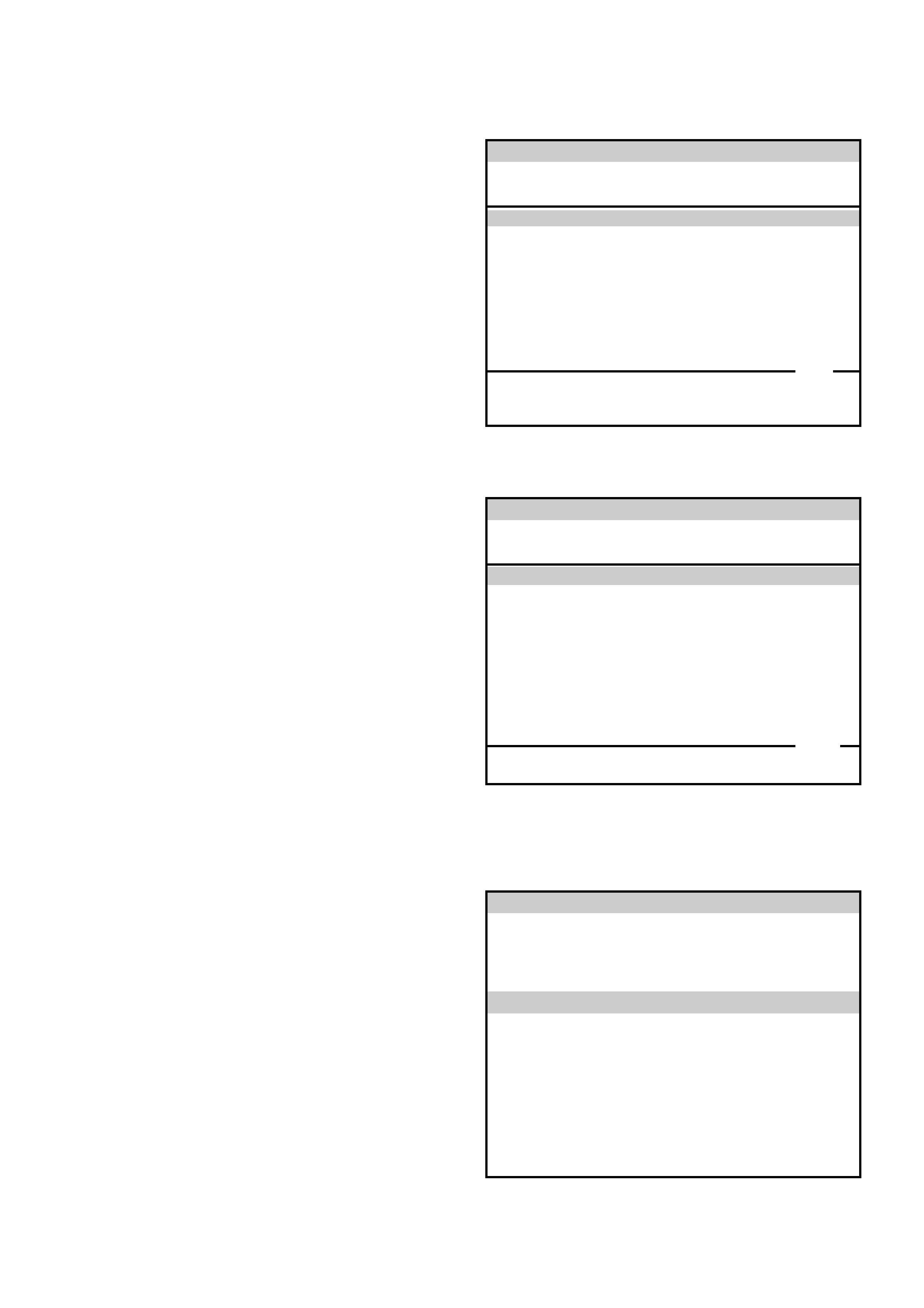
Lifting Point: Front
• When using a floor jack, lift on the Convex portion of
the skid plate.
545RS001
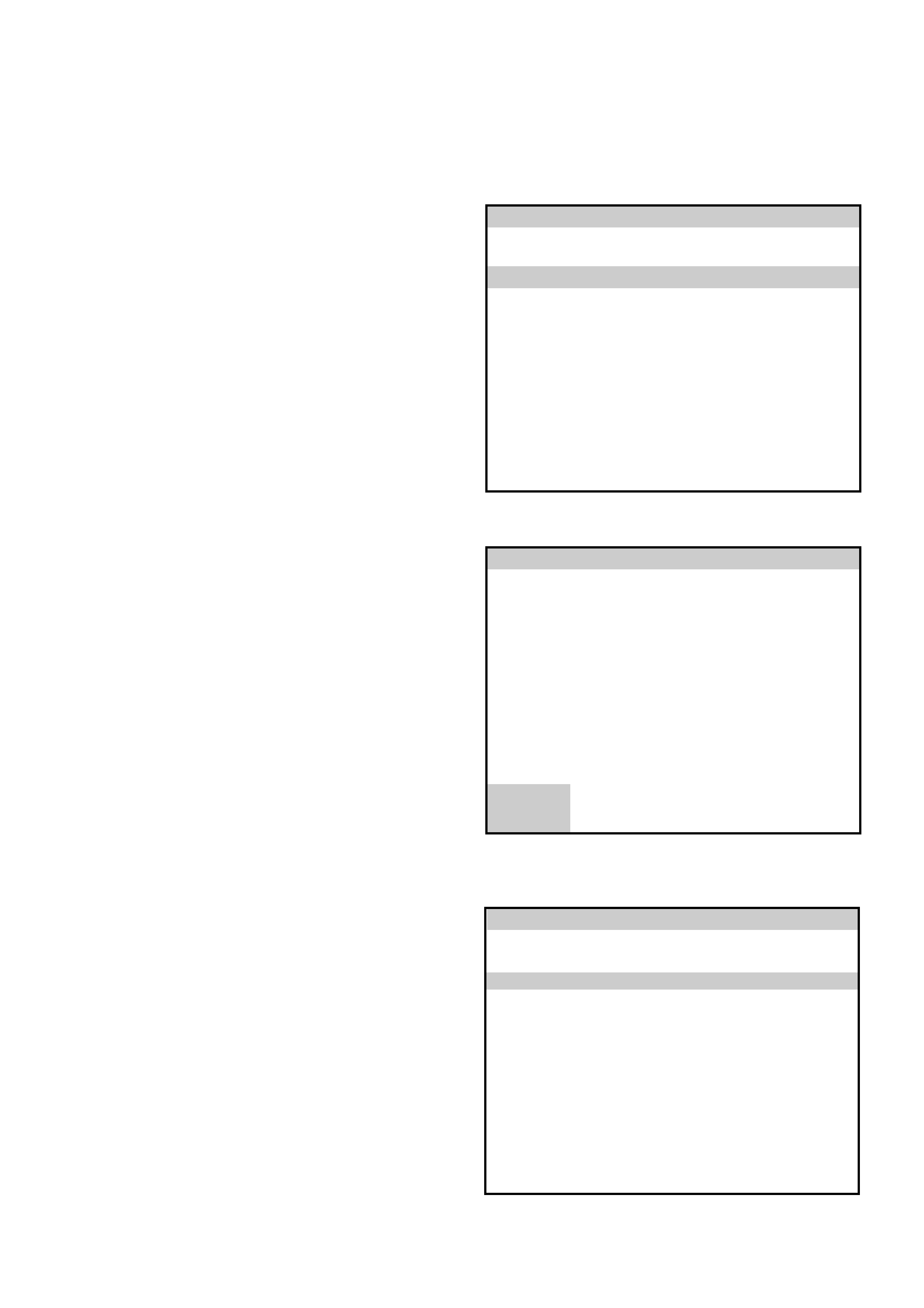
Supportable Point: Front
• Position the chassis stands at the bottom of the frame
sidemember, behind the front wheel.
Procedure
1. Select F3: Actuator Test from the Application
Menu with the arrow keys, then press ENTER.
2. Select F0: Return Pump Relay Test, then press
ENTER
3. Using the softkeys, check the Return Pump
function.
1. Select F3: Actuator Test from the Application
Menu with the arrow keys, then press ENTER.
Application Menu
F0: Diagnostic Trouble Codes
F1: Data Display
F2: Snapsh ot
F3: Actuator Tests
F4: Miscell aneo us Te sts
UES2002abs14
Application Menu
F0: Return Pump Relay Test
F1: Front Left Solenoid Valve Test
F2: Front Right Solenoid Valve Test
F3: Rear Left Solenoid Valve Test
F4: Rear Right Solenoid Valve Test
UES2002abs15
Return Pump Relay Test
(2) 2002 Frontera
Electronic System: ABS
UE2002abs16
On
Return Pump
Off
Front Left Wheel Speed
Front Right Wheel Speed
Rear Wheel Speed
Warning Lamp
ABS State
ABS Relay
4 Wheel Drive
Quit
0 km/h
0 km/h
0 km/h
Off
Off
Active
Inactive
4. Select Solenoid Valve Test from the Application
Menu with the arrow keys, then press ENTER.
5. Press the CONFIRM soft key.
6. Release the brake pedal. Attempt to rotate the
wheel.
Does the wheel rotate?:
YES: Press the YES soft key to go to the next
display.
NO: Press the NO soft key.The test has failed.
Check the hydraulic brake system. Refer to the
Power Assisted Brake Section.
Application Menu
F0: Return Pump Relay Test
F1: Front Left Solenoid Valve Test
F2: Front Right Solenoid Valve Test
F3: Rear Left Solenoid Valve Test
F4: Rear Right Solenoid Valve Test
UES2002abs11
Front Left Solenoid Valve Test
(2) 2002 Frontera
Electronic System: ABS
UE2002abs12
Before Running this Test
See Checking Proce dur e!
Confirm
Front Left Solenoid Valve Test
(2) 2002 Frontera
Electronic System: ABS
UE2002abs13
Normal Funct ion
Brake Switch
Yes
Inactive
Wheel Turnable?
No
7. Depress and hold the brake pedal. Attempt to rotate
the wheel.
Is the wheel blocked?
YES: Press the YES soft key to go to the next
display.
NO: Press the NO soft key.The test has failed.
Check for air in brake system and damaged brake
lines. Refer to the Power Assisted Brake Section.
8. Release the brake pedal. Attempt to rotate the
wheel.
Does the wheel rotate?:
YES: Press the YES soft key to go to the next
display.
NO: Press the NO soft key.The test has failed.
Check the brake disc and caliper. Refer to the
Power Assisted Brake Section.
9. Depress and hold the brake pedal. Attempt to rotate
the wheel.
Does the wheel rotate?:
YES: Press the YES soft key to go to the next
display.
NO: Press the NO soft key.The test has
failed.Check the brake disc and caliper. Refer to the
Power Assisted Brake Section.
Front Left Solenoid Valve Test
(2) 2002 Frontera
Electronic System: ABS
UE2002abs8
Normal Funct ion
Brake Switch
Yes
Active
Wheel Blocked?
No
Front Left Solenoid Valve Test
(2) 2002 Frontera
Electronic System: ABS
UE2002abs9
Normal Function
Brake Switch
Yes
Inactive
Wheel Turn able?
No
Front Left Solenoid Valve Test
(2) 2002 Frontera
Electronic System: ABS
UE2002abs10
Release Function
Brake Switch
Return Pump
Yes
Active
Inactive
Wheel Turn able?
No
10. Depress and hold the brake pedal. Attempt to rotate
the wheel.
Is the wheel blocked?
YES: Press the YES soft key to go to the next
display.
NO: Press the NO soft key.The test has failed.
Check for air in brake system and damaged brake
lines. Refer to the Power Assisted Brake Section.
11. Test is completed. To return to the APPLICATION
MENU, press the CONFIRM soft key
Front Left Solenoid Valve Test
(2) 2002 Frontera
Electronic System: ABS
UE2002abs17
Normal Funct ion
Brake Switch
Yes
Active
Wheel Blocked?
No
Front Left Solenoid Valve Test
(2) 2002 Frontera
Electronic System: ABS
UE2002abs18
Test Passed Successfully!
Confirm

Tech 2 Ser vice Bleed
Procedure
1. Select F4: Miscellaneous Tests from the
Application Menu with the arrow keys, then press
ENTER. Apply the Park Brake. Start the engine and
allow to idle.
2. Select F0: Brake Bleed, then press ENTER
3. Press the CONTINUE soft key
Application Menu
F0: Diagnostic Trouble Codes
F1: Data Display
F2: Snapsh ot
F3: Actuator Tests
F4: Miscell aneo us Te sts
UES2002abs19
Application Menu
F0: Brake Bleed
UES2002abs20
Brake Bleed
(2) 2002 Frontera
Electronic System: ABS
UE2002abs21
1st Time
Perform manual Bleed Procedure Until
Fluid Flows With No Air Present
Continue
Tech 2 Service Bleed
Procedure - Continued
4. Depress and hold the brake pedal. Press the YES
soft key
5. The EHCU will operate the brake bleed function.
6. The first brake bleed cycle is complete.
Brake Bleed
(2) 2002 Frontera
Electronic System: ABS
UE2002abs22
1st Time
Depress And Hold Brake Pedal!
Activate
Yes No
Brake Bleed
(2) 2002 Frontera
Electronic System: ABS
UE2002abs23
1st Time
Depress And Hold Brake Pedal!
Running...
Front Left Solenoid Valve Test
(2) 2002 Frontera
Electronic System: ABS
UE2002abs24
1st Time
Brake Switch Active
Release Brake Pedal!
1st Time Complete

Tech 2 Service Bleed
Procedure - Continued
7. Release the brake pedal. Press the CONTINUE soft
key. The EHCU will repeat the bleed procedure four
times. Brake Bleed
(2) 2002 Frontera
Electronic System: ABS
UE2002abs22
1st Time
1st Time Complete
Continue

Basic Diagnostic Flow Chart
Basic Inspection Pr ocedure
1. Basic Inspection of Service Brake
2. Ground Inspection
Step Action Yes No
1 1. Customer complaint.
2. Question the customer to illicit exact nature of the complaint.
3. Basic inspection (Refer to “Basic inspection procedure")
Using TECH 2? Go to Step 2 Go to Step 4
2 Check for stored DTC’s with Tech 2 by selecting “F0: Diagnostic
Tr oub le Code s" .
Are any DTC’s stored?
Clear code and
check for
repeatability.
Go to Step 3 Go to Step 5
3 1. Repair of faulty part.
2. Clear the DTC with Tech 2..
3. Inspection of “ABS" W/L Illumination pattern with ignition SW
“ON".
4. Test drive.
Does fault reappe ar ?
Repeat the
diagnosis it the
symptom or
DTC appears
again
Go to Step 1 Go to Step 5
4 Check if the DTC is stored or not.
Is a DTCstored?
Clear code and
check for
repeatability
Go to Step 3
Trouble
diagnosis
based on
symptom (Refer
to “Symptom
Diagnosis")
Go to Step 3
5 1. Reconnect all components. Ensure all component are
properly mounted.
2. Clear diagnostic trouble code.
Was this step completed? Finished Go to Step 5
Step Action Yes No
1 Is the fluid level normal?
Go to Step 2
Repleni sh with
fluid
Go to Step 2
2 Does fluid leak? Repair
Go to Step 3 Go to Step 3
3 Is the booster function normal? Go to Step 4 Repair
Go to Step 4
4 Is the pad and rotor condition normal? Go to Step 5 Repair
Go to Step 5
5 Reconnect all components. Ensure all component are properly
mounted.
Was this step completed? Finished Go to Step 5
Step Action Yes No
1 Do all ABS—related ground points have less than 5 ohms
resistance to the battery negative terminal? Go to Step 2 Repair
Go to Step 2
2 Reconnect all components. Ensure all component are properly
mounted.
Was this step completed? Finished Go to Step 2

EHCU Connector Pin-out Checks
• Disconnect Electronic Hydraulic Control Module.
• Perform checks with high impedance digital
multimeter 5-8840-0366-0 or equivalent.
No. Circuit to be Tested Ignition
Switch
Position
Multimeter
Scale/Range Measure
between Pin
Number
Nominal Value Note
1 Power supply OFF 20DCV 1 (C–5)
2 (C–5) 11.5V to 14.5V
2 Ignition enable OFF 20DCV 1 (C–4)
7 (C–4) 0V to 0.1V
ON 20DCV 1 (C–4)
7 (C–4) 11.5V to 14.5V
3 Stoplamp switch OFF 20DCV 13 (C–4)
7 (C–4) 10.5V to 14.5V Press brake pedal
4 Ground connection OFF 200W 7 (C–4)
Ground Less than 2W
OFF 1W 2 (C–5)
Ground Less than 0.2W
5 FL speed se ns or OFF 2kW 2 (C–4)
10 (C–4) 0.7kW to 1.5kW Internal Resistance
OFF 200kW 2 (C–4)
7 (C–4) more than
100kW Insulation Resistance
OFF 200mACV 2 (C–4)
10 (C–4) more than
200mV Turn wheel at 1RPS
6 FR speed sensor OFF 2kW 3 (C–4)
11 (C–4) 0.7kW to 1.5kW Internal Resistance
OFF 200kW 3 (C–4)
7 (C–4) more than
100kW Insulation Resistance
OFF 200mACV 3 (C–4)
11 (C–4) more than
200mV Turn wheel at 1RPS
7 RR speed sensor OFF 2kW 4 (C–4)
12 (C–4) 1.0kW to 1.7kW Internal Resistance
OFF 200kW 4 (C–4)
7 (C–4) more than
100kW Insulation Resistance
OFF 200mACV 4 (C–4)
12 (C–4) more than
200mV Turn wheel at 1RPS
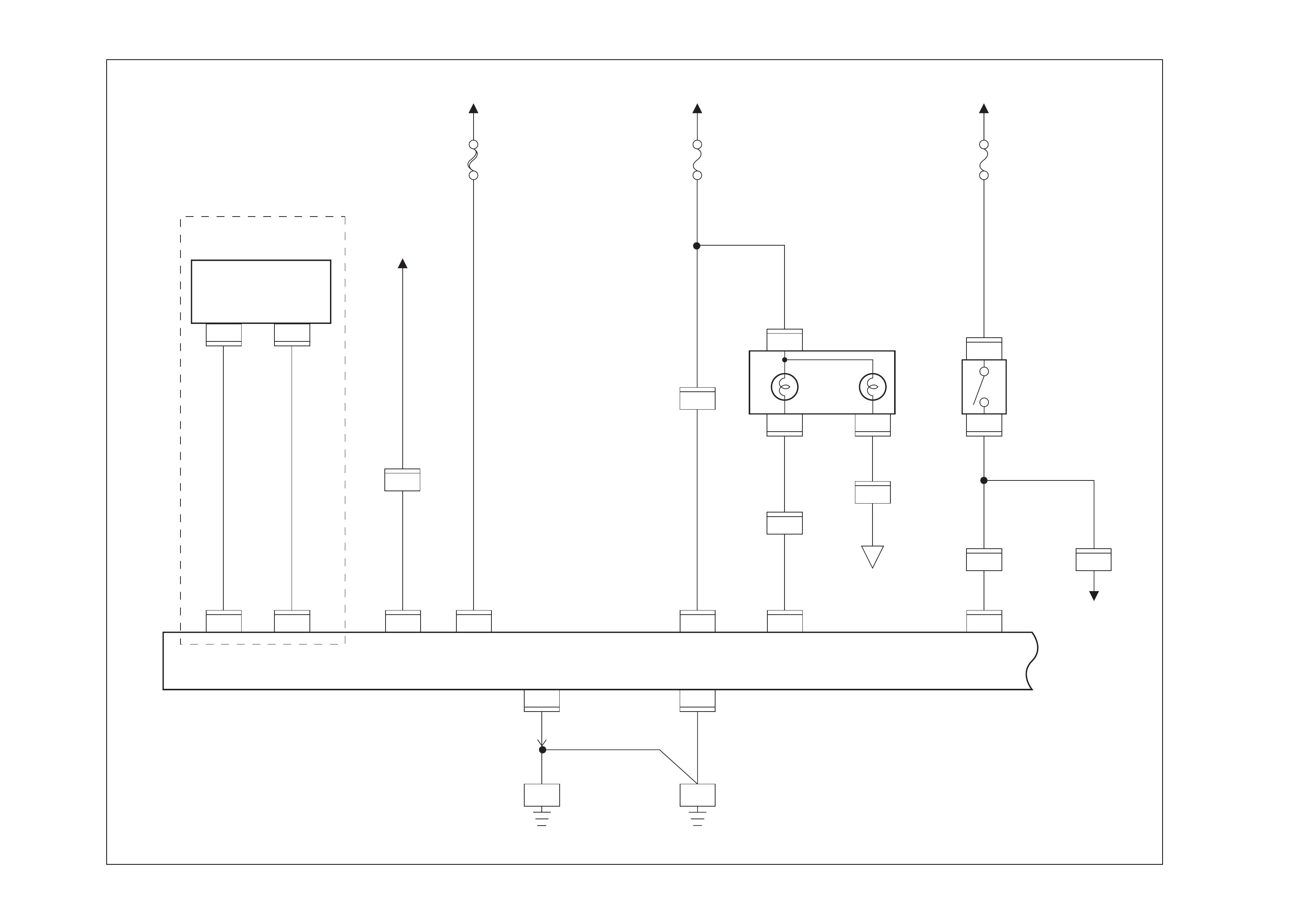
Circuit Diagram
D08R100134
5.0
WHT/GRN
0.85
PNK/
GRN
50A
ABS
INDICATOR
LIGHT(METER)
STOP
LAMP
SW
ELECTRONIC
HYDRAULIC
CONTROL UNIT
1
C-5
0.85
YEL
0.85
YEL
0.85
YEL
0.85
BLK
3.0
BLK/RED
STARTER SW
(IG1)
15A
METER
I-23I-24
14
I-24
10
H-14
19
H-15 18
H-14
9
C-6014
C-6011
22
3.0
WHT 15A
STOP LAMP
BATT.(+)BATT.(+)
STOP LAMP
13
C-4
8
0.85
GRN
0.85
RED
0.85
RED
0.5
RED
0.85
RED
I-31
H-14 15
H-16
1
I-31
4
1
C-4
C-10
H-14
11
C-4
7
6
C-4
0.85
YEL
0.5
PPL/WHT
0.5
PPL/WHT
0.5
O
0.5
O
8
C-4
0.5
P
8
C-4
0.5
LG/R
5
C-4
3.0
BLK
5.0
BLK
C-26
E/ROOM LH
C-5
GROUND GROUND
BATTERY(+) POWER
SUPPLY SILA BRAKE LAMP
SWITCH
2
BATT TRAY
BRAKE
ABS
A
TOD
CONTROL
UNIT
4WD
CONTROL
UNIT
(14)
With TOD
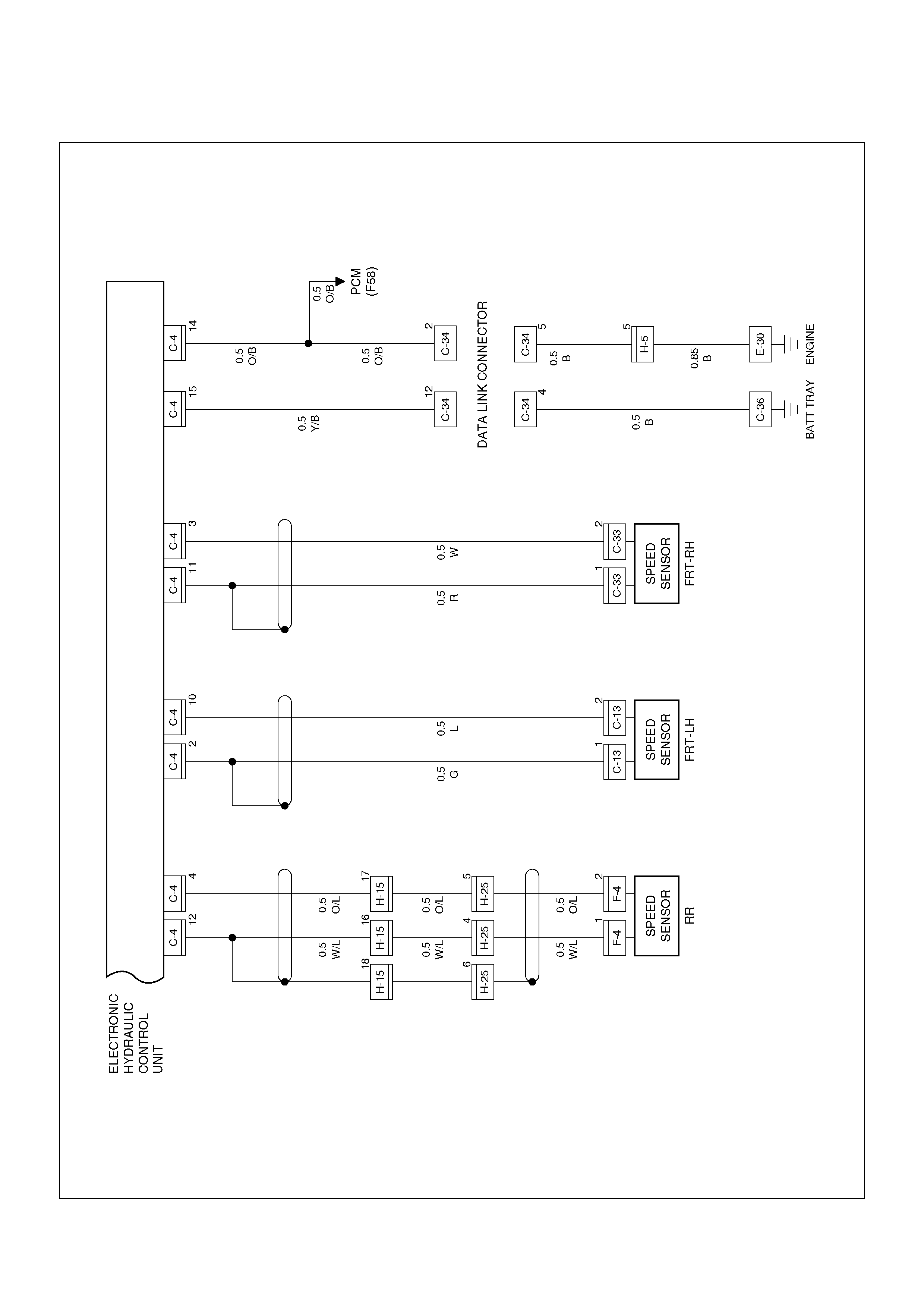
D08R100135
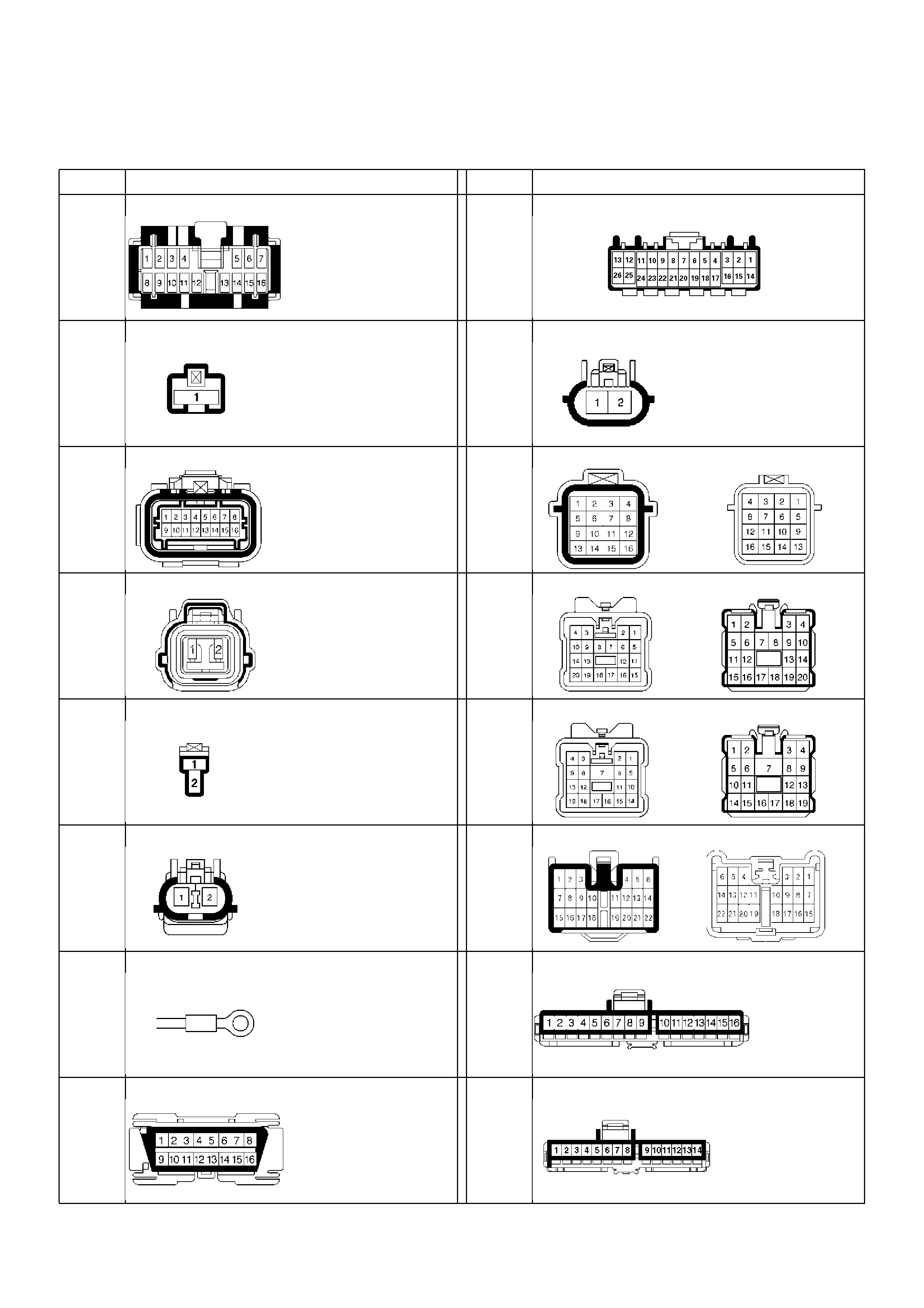
Connector List
No. Connector face No. Connector face
B-19 C-60
B-23 F-4
C-4 H-5
C-5 H-15
H-25
C-6 H-14
C-13
C-33 H-19
C-16
E-30 I-1
C-34 I-2

I-18 I-45
No. Connector face No. Connector face
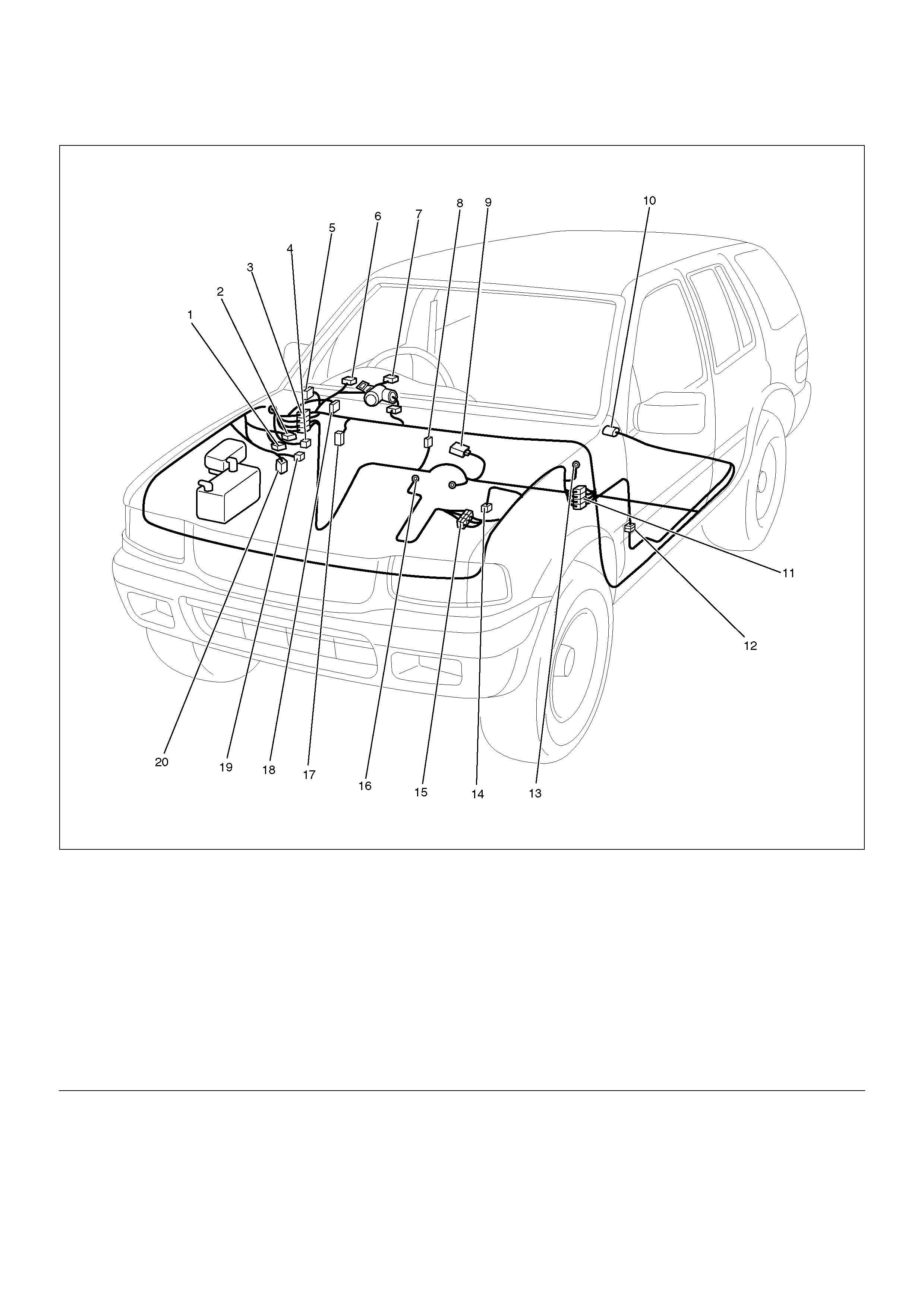
Part Location
D08R100072
Legend
EndOFCallout
(1) C–5
(2) C–4
(3) H– 14, H–19
(4) C–60
(5) I–45 (Relay & Fuse Box)
(6) I–1
(7) I–2
(8) B–23
(9) B–19
(10) F–4
(11) H–15
(12) H–25
(13) C–16
(14) C–13
(15) H–5
(16) E–30
(17) I–18
(18) C–34
(19) C–6
(20) C–33

Symp tom Diagnosis
A number of braking system faults may occur that will not illuminate the “ABS” warning lamp. These are all attributable
to probl ems whi ch cannot be detec ted by EHCU sel f-diagno sis. Anal yse the custom er compl aint and conduct a road
test to determine which symptom is present, then follow the appropriate flow chart listed below.
Chart A-1 ABS Operates Frequently But The Vehicle Does Not Decelerate
No. Symptom Diagnostic Flow Charts
Without TECH 2 With TECH 2
1 ABS operates frequently but the vehicle does not decelerate. Chart A-1 Chart TA-1
2 Uneven braking occurs while ABS operates. Chart A-2 Chart TA-2
3 The wheels lock during braking. Chart A-3 Chart TA-3
4 Abnormal brake pedal feel. Chart A-4 —
5 The EHCU is heard operating while not braking. Chart A-5 Chart TA-5
Step Action Yes No
1 Is braking force distributed correctly between front and rear of
vehicle? Go to Step 2
Repair brake
components.
Go to Step 7
2 Are axle and hub components installed correctly?
Go to Step 3
Repair axles
and hubs.
Go to Step 7
3 Is there movement in any wheel speed sensor mounting? Repair wheel
speed sensor.
Go to Step 7 Go to Step 4
4 Is there any damage, or powered iron residue sticking to any
wheel speed sensor/sensor ring? Replace sensor
or sensor ring.
Go to Step 7 Go to Step 5
5 Is the output of each wheel speed sensor normal? (Refer to chart
C-1 or TC-1)
Go to Step 6
Replace wheel
speed sensor or
repair harness.
Go to Step 7
6 Is the 4WD/TOD control unit functioning correctly?
Go to Step 7
Replace 4WD/
TOD control
unit or repair
harness.
Go to Step 7
7 Reconnect all components, ensure all components are properly
mounted.
Was this step complet ed?
Repeat the “Basic
diagnostic flow
chart" Go to Step 7

Chart TA-1 ABS Operates Freque n t ly But The Vehicle Does Not Decelerate (Use TECH 2)
Chart A-2 Uneven Braking Occurs While ABS Operates
Chart TA-2 Uneven Braking Occurs While ABS Operates (Use TECH 2)
Step Action Yes No
1 1. Connect TECH 2.
2. Make sure of the output conditions of each sensor.
Is the output of each sensor correct? Go to Step 2
Replace wheel
speed sensor.
Go to Step 3
2 Return to Chart A-1.
Was the Chart A-1 completed? Go to Step 3 Go to Step 2
3 Reconnect all components, ensure all components are properly
mounted.
Was this step complet ed?
Repeat the “Basic
diagnostic flow
chart" Go to Step 3
Step Action Yes No
1 Is there movement in any sensor mounting? Repair.
Go to Step 5 Go to Step 2
2 Dam age or powdered iron residue sticking to any sensor/sensor
ring? Repair.
Go to Step 5 Go to Step 3
3 Is the output of each wheel speed sensor correct? (Refer to chart
C-1 or TC-1)
Go to Step 4
Replace sensor
or repair
harness.
Go to Step 5
4 Are the brake hydraulic pipes connected to the correct EHCU
ports? Replace H/U.
Go to Step 5
Reconnect
brake pipe
correctly.
Go to Step 5
5 Reconnect all components, ensure all components are properly
mounted.
Was this step complet ed?
Repeat the “Basic
diagnostic flow
chart" Go to Step 5
Step Action Yes No
1 1. Connect TECH 2.
2. Make sure of the output conditions of each wheel speed
sensor.
Is the output of each sensor correct? Go to Step 2 Go to Step 3
2 Check brake pipe connections by TECH 2 ACTUATOR TEST
Are the pipes connected correctly? Replace EHCU.
Go to Step 4 Repair the pipe.
Go to Step 4
3 Repair and check the wheel speed sensor (Refer to chart B-20 to
B-23 , C-1 or TC-1).
Was each chart completed? Go to Step 4 Go to Step 3
4 Reconnect all components, ensure all components are properly
mounted.
Was this step complet ed?
Repeat the “Basic
diagnostic flow
chart" Go to Step 4

Chart A-3, TA-3 The Wheels Are Locked During Braking
Chart A-4 Abnormal Brake Pedal Feel
Step Action Yes No
1 Is ABS working? Go to Step 2 Go to Step 4
2 Is vehicle speed under 10 km/h? Go to Step 3 Normal.
3 Are the wheel speed sensor outputs correct? (Chart C-1 or TC-1)
Go to Step 4
Replace sensor
or repair
harness.
Go to Step 6
4 Is the 4WD/TOD control unit functioning correctly?
Go to Step 5
Replace 4WD /
TOD control
unit or repair
harness.
Go to Step 6
5 Do the EHCU ground circuits have less than 5 Ohms resistance
to the battery negative terminal? Replace EHCU.
Go to Step 6 Repair.
Go to Step 6
6 Reconnect all components, ensure all components are properly
mounted.
Was this step complet ed?
Repeat the “Basic
diagnostic flow
chart" Go to Step 6
Step Action Yes No
1 Is the stop lamp actuated when the brake pedal is depressed? Go to Step 2 Go to Step 3
2 1. Turn the ignition switch off.
2. Disconnect the EHCU connector.
3. Actuate the stop lamp switch.
Is the voltage between EHCU connector terminals 13 & 7 less
than battery voltage? Go to Step 4
Repair harness
between brake
SW and EHCU.
Go to Step 6
3 Is stop lamp fuse OK?
Go to Step 5
Replace sto p
lamp fuse.
Go to Step 6
4 Is there less than 5 ohms resistance between EHCU connector
terminal 7 and the battery negative terminal? Go to Step 6
Repair ground
circuit
Go to Step 6
5 Is brake SW OK? Repair stop
lamp harness.
Go to Step 6
Replace brake
SW.
Go to Step 6
6 Reconnect all components, ensure all components are properly
mounted.
Was this step complet ed?
Repeat the “Basic
diagnostic flow
chart" Go to Step 6

Chart A-5, TA-5 EHCU Is Heard Operating While Not Braking
Step Action Yes No
1 Is this the first vehicle movement after engine start? System
Self-Test.
Sound is
Normal. Go to Step 2
2 Is vehicle speed under 10 km/h? System
Self-Test.
Sound is
Normal. Go to Step 3
3 Does the noise occur during any of the following conditions:
• Transmission downshift or clutch operation.
• Driving on low road friction roads or rough roads.
• Performing a high-speed turn.
• When operating electrical switches.
• When engine exceeds 5000 rpm.
ABS EHCU may
sometimes be
actuated under
these conditions
even when brake
pedal is not
applied. Go to Step 4
4 Is there play in each or any sensor/wheel speed sensor rings? Repair.
Go to Step 7 Go to Step 5
5 Is there any damage or powdered iron residue sticking to any
sensor/wheel speed sensor ring? Repair.
Go to Step 7 Go to Step 6
6 Is each sensor output correct? (Refer to chart C-1 or TC-1). Check harness/
connector for
suspected open
circuit
If no open
circuit is found,
replace Coil
integrated
module.
Go to Step 7 Repair.
Go to Step 7
7 Reconnect all components, ensure all components are properly
mounted.
Was this step complet ed?
Repeat the “Basic
diagnostic flow
chart" Go to Step 7

Diagnostic Trouble Codes
Choose and trace an appropriate flowchart by the
numbers listed below to find fault and repair.
Diagnostic Trouble
Code (DTC) Diagnosis Item Chart
No.
————
C0285 4WD/TOD Control Unit 4WD signal failure Wiring B-8
C0271 RAM read/write error
Coil
Integrated
Module B-2
C0272 ROM check sum er ror
C0270 CPU function error
C0273 Inoperative isolation item
C0284 Loop time overrun
C0277 Low ignition voltage Wiring B-3
C0278 High ignition voltage
C0269 Excessive dump time Coil
Integrated
Module
B-4
C0274 Excessive isolation time B-5
C0276 G-Sen so r Fail ur e B-6
C0281 Brake switch Failure B-7
C0282 Open or shorted 4¥4 input signal (Without TOD) Wiring B-8
C0267 Open motor circuit or shorted ECU output Motor B-9
C0268 St a lled motor or open ECU output
C0265 Open relay circuit Relay B-10
C0266 Shorted relay circuit
C0245 FL Open isolation solenoid or shorted ECU output
Solenoid
B-11
C0247 FL Shorted isolation solenoid or open ECU output
C0246 FL Open dump solenoid or shorted ECU output B-12
C0248 FL Shorted dump solenoid or open ECU output
C0241 FR Open isolation solenoid or shorted ECU output B-13
C0243 FR Shorted isolation solenoid or open ECU output
C0242 FR Open dump solenoid or shorted ECU output B-14
C0244 FR Shorted dump solenoid or open ECU output
C0251 Rear Open isolation solenoid or shorted ECU output B-15
C0253 Rear Shorted isolation solenoid or open ECU output
C0252 Rear Open dum p solenoi d or shor ted ECU outp ut B-16
C0254 Rear Shorted dump solenoid or open ECU output

C0225 FL Open or shorted sensor
Sensor or
Wiring
B-17
C0221 FR Open or shorted sensor B-18
C0235 Rear Open or shorted sensor B-19
C0226 FL Missing sensor signal B-20
C0227 FL Sensor signal dropout
C0222 FR Missing sensor signal B-21
C0223 FR Sensor signal dropout
C0236 Rear Missing sensor signal B-22
C0237 Rear Sensor signal dropout
C0229 Simultaneous dropout of front sensor signal B-23
C0238 Wheel speed error Vehicle or
Sensor B-24
C0286 Shorted indicator lamp Wiring —
C0287 Open or Shorted TOD Control Unit Circuit (With
TOD) Wiring B-25
Diagnostic Trouble
Code (DTC) Diagnosis Item Chart
No.
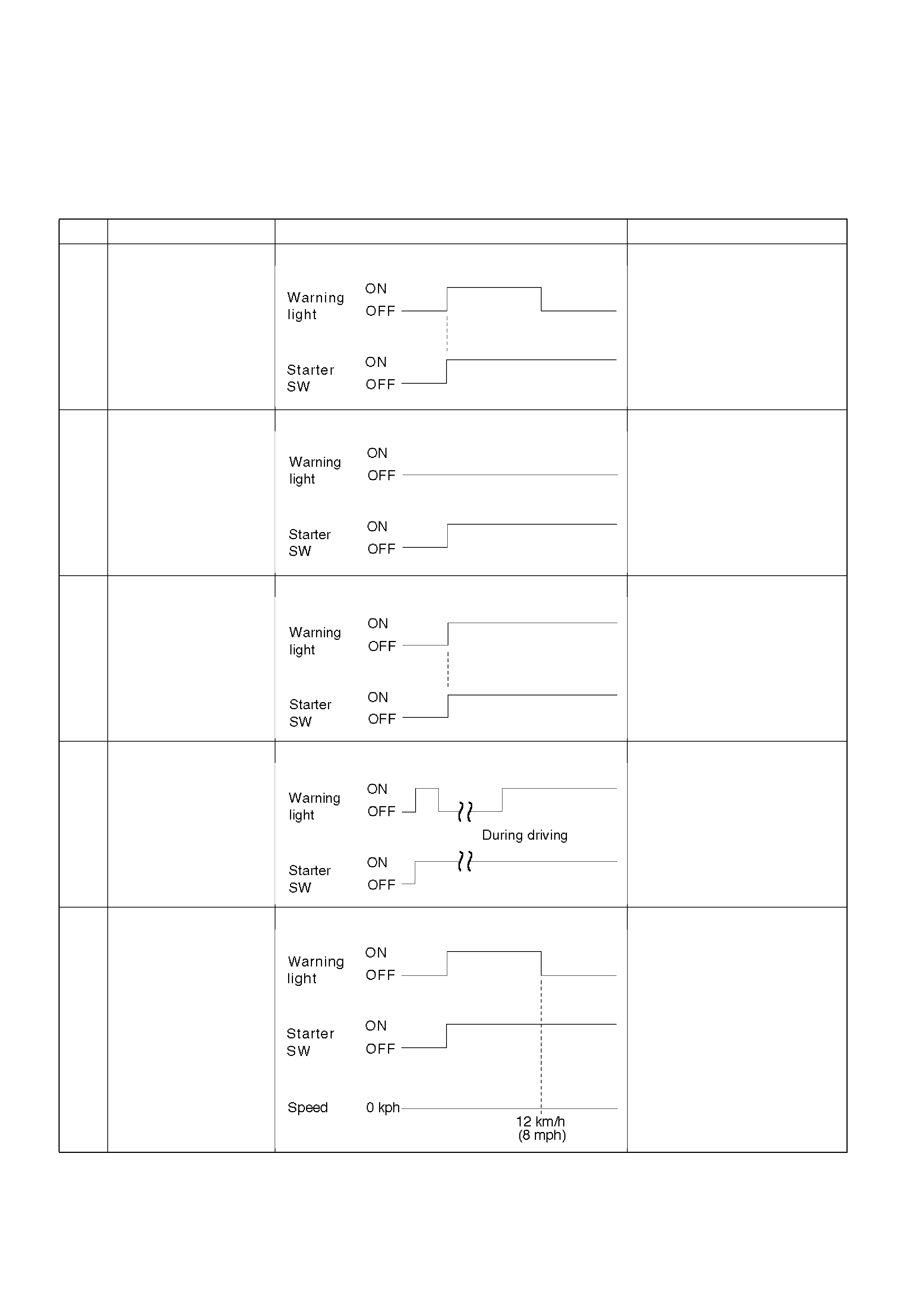
Diagnosis By “ABS" Warning Lamp
Illumination Pattern
In the event that there is abnormality in the “ABS"
warning lamp illumination pattern while the key is in the
ON position or if the warning lamp is actuated during
driving, trouble should be diagnosed on a illumination
pattern basis as follows:
No. Condition “ABS" Warning Lamp Illumination Pattern Diagnostic
1 Normal “ABS” warning
lamp operation Normal - No DTCs stored
2 Warning lamp is not lit Warning lamp circuit failure
ÆGo to Chart B-1
3 W arning lamp remains
ON Diagnostic trouble codes are
stored.
Display diagnostic trouble
codes with Tech 2 and
diagnose on a code basis
according to the flow charts.
4 Warning lamp is
actuated whil e driv ing Diagnostic trouble codes are
stored.
Display diagnostic trouble
codes with Tech 2 and
diagnose on a code basis
according to the flow charts.
5 Warning lamp goes at
12 km/h (8 mph) or
higher (After repairing
the faulty part)
After repairing the fault, the
warning lamp does not
extinguish even though the
DTC/s have been cleared with
Tech 2
Turn the ignition switch to the
ON position and drive the
vehicle at 12 km/h or higher to
extinguish the warning lamp.

Chart B-1 Warning Lamp (W/L) is not activated when the ignition is first turned ON .
Chart B-2 CPU Error (D TC C0271, C0272, C0273, C0284)
Step Action Yes No
1 Has the W/L fuse failed? Replace fuse.
Go to Step 5 Go to Step 2
2 Has the W/L bulb failed? Replace W/L
bulb.
Go to Step 5 Go to Step 3
3 1. Turn the key off.
2. Disconnect coil integrated module connector (C-4).
3. Turn the key ON.
Is the check voltage between coil integrated module connector
(C-4) terminals 6 and 7 less than battery voltage? Go to Step 4
Repair harness
and connector.
Go to Step 5
4 Is there continuity between coil integrated module connector
(C-4) terminals, 1 and 7 and body ground?. No fault found:
Replace EHCU.
Go to Step 5
Repair harness
and connector.
Go to Step 5
5 Reconnect all components, ensure all components are properly
mounted.
Was this step complet ed?
Repeat the “Basic
diagnostic flow
chart" Go to Step 5
Step Action Yes No
1 1. Turn the key off.
2. Disconnect coil integrated module connector.
3. Inspe ct coil int egr ate d module g round .
Is the resistance between the coil integrated module connector
terminals, 2 (C-5) and 7 (C-4) and battery negative terminal less
than 5 Ohms? Go to Step 2
Repair the body
ground
harness.
Go to Step 3
2 1. Turn the key off, connect the coil integrated module
connector.
2. Erase the trouble code.
3. Turn Ignition off, then on, to perform system self-check.
4. If warning lamp remains on, display trouble codes once
again.
Are any of the folowing DTCs set? - C0271, C0272, C0273,
C0284 Replace EHCU.
Go to Step 3
Inspect in
accordance with
the DTC displayed.
3 1. Reconnect all components, ensure all components are
properly mounted.
2. Clear any DTCs.
Was this step complet ed?
Repeat the “Basic
diagnostic flow
chart" Go to Step 3

Chart B-3 Low or High Ignition Voltage (DTC C0277, 0278 )
Char t B-4 Excessive Dump Time (DTC C0269)
Chart B-5 Exc essi ve Isolation Time (DTC C0274)
Step Action Yes No
1 Is battery voltage to specification?
Go to Step 2
Charge or
replace battery.
Go to Step 2
2 1. Turn the key off.
2. Disconnect coil integrated module connector.
3. Turn the key on.
Is the voltage between coil integrated module connector (C-4)
terminals 1 and 7, higher than 10V?
Check harness
connector for
suspected
disconnection
Fault found:
Repair, and
perform system
self-check
No fault found:
replace EHCU.
Go to Step 3
Repair harness
or connector.
Go to Step 3
3 1. Reconnect all components, ensure all components are
properly mounted.
2. Clear diagnostic trouble code.
Was this step complet ed?
Repeat the “Basic
diagnostic flow
chart" Go to Step 3
Step Action Yes No
1 Check for anything ca us ing exten ded AB S act ivati on, su ch as
locked brakes or an erratic speed sensor signal.
Was a problem found? Repair or Replace Go to Step 2
2 1. The key turned off.
2. Replace EHCU.
3. Reconnect all components, ensure all components are
properly mounted.
Was this step complet ed?
Repeat the “Basic
diagnostic flow
chart" Go to Step 2

Chart B-6 G-Sensor Output Failure (DTC C0276 )
Chart B-7 Brake Switch Failure (DTC C0281)
Step Action Yes No
1 1. Turn the key off.
2. Replace EHCU.
3. Reconnect all components, ensure all components are
properly mounted.
Was this step complet ed?
Repeat the “Basic
diagnostic flow
chart" Go to Step 1
Step Action Yes No
1 Is the stop lamp actuated when the brake pedal is depressed? Go to Step 2 Go to Step 4
2 1. Turn the key off.
2. Disc onn ec ted co il int egrate d modu le con nector.
Is the voltage at coil integrated module connector (C-4) terminals
13 to 7 when brake pedal is depressed less than battery voltage?
Go to Step 3
Harness
between brake
SW and coil
integrated
module is faulty.
Go to Step 6
3 Do C-5 connector pin 2, and C-4 connector pin 7 have less than
5 ohms resistance to the battery negative terminal? No fault found:
replace EHCU.
Go to Step 6 Repair.
Go to Step 6
4 Is stop lamp fuse OK? Go to Step 5 Replace.
Go to Step 6
5 Is the brake SW functioning correctly? Repair the stop
lampharness.
Go to Step 6 Replace.
Go to Step 6
6 1. Reconnect all components, ensure all components are
properly mounted.
2. Clear diagnostic trouble code.
Was this step complet ed?
Repeat the “Basic
diagnostic flow
chart" Go to Step 6

Chart B-8 4WD/TOD Control Unit Failure( DTC C0285), 4WD State Input Signal Failure (DTC
C0282)
Chart B - 9 Pump Motor Failure (DT C C0267, C0268)
Step Action Yes No
1 Remove coil integrated module connector.
Is there continuity between coil integrated module connector
(C-4) terminal 8 and terminal 14 at the 4WD/TOD Control Unit? Go to Step 2 Repair.
Go to Step 3
2 Is the 4WD/TOD control unit OK?
Replace EHCU.
Go to Step 3
Replace 4WD/
TOD control
unit.
Go to Step 3
3 1. Reconnect all components, ensure all components are
properly mounted.
2. Clear DTCs.
Was this step complet ed?
Repeat the “Basic
diagnostic flow
chart" Go to Step 3
Step Action Yes No
1 1. Turn the key off.
2. Disconnect coil integrated module connector.
3. Measure the voltage between terminal 1 of the coil integrated
module connector (C-5) and body ground.
Is the voltage equal to battery voltage?
Go to Step 2
Repair fuse/
harness
between battery
and coil
integrated
module
connector (C-5)
terminal 1.
Go to Step 5
2 Is the harness from the hydraulic unit connected to the coil
integra ted mod ule conne ct or ? Go to Step 3
Connect to the
connector.
Go to Step 3
3 Is the harness from the hydraulic unit OK? Go to Step 4 Replace EHCU.
Go to Step 5
4 Is the resistance of hydraulic unit connector terminals 1 and 2
between 0.2 and 1.0 ohms? Replace EHCU.
Go to Step 5 Replace EHCU.
Go to Step 5
5 1. Reconnect all components, ensure all components are
properly mounted.
2. Clear diagnostic trouble code.
Was this step complet ed?
Repeat the “Basic
diagnostic flow
chart" Go to Step 5

Chart B-10 EHCU Valve Relay Failure (DTC C0265, C0266 )
Chart B-11 FL Isolation Solenoid Coil Failure (DTC 41 C0245, C024 7)
Chart B-12 FL Dump Solenoid Coil Failure (DTC C0246, C0248)
Step Action Yes No
1 1. Turn the key off.
2. Disconnect coil integrated module connector.
3. Measure the voltage between terminal 1 of the coil integrated
module connector (C-5) and body ground.
Is the voltage equal to battery voltage?
Replace EHCU.
Go to Step 2
Repair fuse and
harness coil
integrated
module
connector (C-5)
terminal 1 and
battery.
Go to Step 2
2 1. Reconnect all components, ensure all components are
properly mounted.
2. Clear diagnostic trouble code.
Was this step complet ed?
Repeat the “Basic
diagnostic flow
chart" Go to Step 2
Step Action Yes No
1 Was the “EHCU Connector Pin–out Checks" performed?
Go to Step 2
Go to “EHCU
Connector Pin–out
Checks."
2 1. Turn the key switch to off.
2. Disconnect the 2–way EHCU connector (C–5) from the
EHCU.
3. Inspect the connector for damage or corrosion.
Is the connector free from damage or corrosion? Go to Step 3
Repair the
connector . Repeat
the “Basic
Diagnostic Flow
Chart."
3 1. Replace the Coil Integrated Module.
2. Reconnect all component, ensure all components are
properly mounted.
Was this step complet ed?
Repeat the “Basic
diagnostic flow
chart" Go to Step 3
Step Action Yes No
1 Was the “EHCU Connector Pin–out Checks" performed?
Go to Step 2
Go to “EHCU
Connector Pin–out
Checks."
2 1. Turn the key switch to off.
2. Disconnect the 2–way EHCU connector (C–5) from the
EHCU.
3. Inspect the connector for damage or corrosion.
Is the connector free from damage or corrosion? Go to Step 3
Repair the
connector . Repeat
the “Basic
Diagnostic Flow
Chart."
3 1. Replace the Coil Integrated Module.
2. Reconnect all component, ensure all components are
properly mounted.
Was this step complet ed?
Repeat the “Basic
diagnostic flow
chart" Go to Step 3

Chart B-13 FR Isolation Solenoid Coil Failure (DTC C0241, C0243 )
Chart B-14 FR Dump Solenoid Coil Failure (DTC C0242, C0244)
Chart B-15 Rear Isolation Solenoid Coil Failure (DTC C0251, C0253)
Step Action Yes No
1 Was the “EHCU Connector Pin–out Checks" performed?
Go to Step 2
Go to “EHCU
Connector Pin–out
Checks."
2 1. Turn the key switch to off.
2. Disconnect the 2–way EHCU connector (C–5) from the
EHCU.
3. Inspect the connector for damage or corrosion.
Is the connector free from damage or corrosion? Go to Step 3
Repair the
connector . Repeat
the “Basic
Diagnostic Flow
Chart."
3 1. Replace the Coil Integrated Module.
2. Reconnect all component, ensure all components are
properly mounted.
Was this step complet ed?
Repeat the “Basic
diagnostic flow
chart" Go to Step 3

Chart B-16 Rear Dump Solenoid Coil Failure (DTC C0252, C0254)
Chart B-17 FL Speed Sensor Open or Shorted (DTC C0225)
Step Action Yes No
1 Was the “EHCU Connector Pin–out Checks" performed?
Go to Step 2
Go to “EHCU
Connector Pin–out
Checks."
2 1. Turn the key switch to off.
2. Disconnect the 2–way EHCU connector (C–5) from the
EHCU.
3. Inspect the connector for damage or corrosion.
Is the connector free from damage or corrosion? Go to Step 3
Repair the
connector . Repeat
the “Basic
Diagnostic Flow
Chart."
3 1. Replace the Coil Integrated Module.
2. Reconnect all component, ensure all components are
properly mounted.
Was this step complet ed?
Repeat the “Basic
diagnostic flow
chart" Go to Step 3
Step Action Yes No
1 1. Turn the key off.
2. Disconnect coil integrated module connector.
3. Measure the resistance between coil integrated module
connector (C-4) terminals 2 and 10.
Is the resistance between 0.7k and 1.5k ohms?
Replace coil
integrated
module.
Go to Step 3
Check for faults
in harness
between speed
sensor and coil
integrated
module.
Repair, and
perform system
self-check.
If no fault is found
with harness
Go to Step 2
2 Measure the FL speed sensor resistance at the sensor
connector.
Is the resistance between 0.7k and 1.5k ohms? Go to Step 3
Replace
sensor.
Go to Step 3
3 1. Reconnect all components, ensure all components are
properly mounted.
2. Clear diagnostic trouble code.
Was this step complet ed?
Repeat the “Basic
diagnostic flow
chart" Go to Step 3

Chart B-18 FR Speed Sensor Open or Shorted (DTC C0221
Step Action Yes No
1 1. Turn the key off.
2. Disconnect coil integrated module connector.
3. Measure the resistance between coil integrated module
connector (C-4) terminals 3 and 11.
Is the resistance between 0.7k and 1.5k ohms?
Replace coil
integrated
module.
Go to Step 3
Check for faults
in harness
between speed
sensor and coil
integrated
module.
Repair, and
perform system
self-check.
If no fault is found
with harness
Go to Step 2
2 Measure the FR speed sensor resistance at the sensor
connector.
Is the resistance between 0.7k and 1.5k ohms? Go to Step 3
Replace
sensor.
Go to Step 3
3 1. Reconnect all components, ensure all components are
properly mounted.
2. Clear diagnostic trouble code.
Was this step complet ed?
Repeat the “Basic
diagnostic flow
chart" Go to Step 3

Chart B-19 Rear Speed Sensor Open or Shorted (DTC C0235)
Step Action Yes No
1 1. Turn the key off.
2. Disconnect coil integrated module connector.
3. Measure the resistance between coil integrated module
connector (C-4) terminals 4 and 12.
Is the resistance between 1.0k and 1.7k ohms?
Replace coil
integrated
module.
Go to Step 3
Check for faults
in harness
between speed
sensor and coil
integrated
module.
Repair, and
perform system
self-check.
If no fault is found
with harness
Go to Step 2
2 Measure the Rear speed sensor resistance at the sensor
connector.
Is the resistance between 1.0k and 1.7k ohms? Go to Step 3
Replace
sensor.
Go to Step 3
3 1. Reconnect all components, ensure all components are
properly mounted.
2. Clear diagnostic trouble code.
Was this step complet ed?
Repeat the “Basic
diagnostic flow
chart" Go to Step 3

Chart B-20 FL Speed Sensor Signal Missing (DTC C0226, C0227)
NOTE: After clearing the DTCs with Tech 2, drive the
vehicle above 12km/h and ensure the “ABS” warning
lamp goes out.
Step Action Yes No
1 1. Turn the key off.
2. Disconnect coil integrated module connector.
3. Measure the FL speed sensor resistance between coil
integrated module connector (C-4) terminals 2 and 10.
Is the resistance between 0.7k and 1.5k ohms? Go to Step 2 Go to Step 3
2 Is there any movement in the sensor/sensor rotor? Repair.
Go to Step 6 Go to Step 4
3 Measure the FL speed sensor resistance at the sensor
connector.
Is the resistance between 0.7k and 1.5k ohms?
Repair harness
abnormality
between
sensors and
coil integrated
module.
Go to Step 6
Replace
sensor.
Go to Step 6
4 Is there any damage and powered iron sticking to sensor/sensor
ring? Repair.
Go to Step 6 Go to Step 5
5 Is sensor output normal? (Chart C-1-1 or TC-1) Check for faults
in harness
between speed
sens or an d coi l
integrated
module.
Fault found:
repair, and
perform system
self-check.
No fault found:
replace EHCU.
Go to Step 6
Replace
sensor.
Go to Step 6
6 1. Reconnect all components, ensure all components are
properly mounted.
2. Clear the DTCs.
Was this step complet ed?
Repeat the “Basic
diagnostic flow
chart" Go to Step 6

Chart B-21 FR Speed Sensor Signal Missing (DTC C0222, C0223)
NOTE: After clearing the DTCs with Tech 2, drive the
vehicle above 12km/h and ensure the “ABS” warning
lamp goes out.
Step Action Yes No
1 1. Turn the key off.
2. Disconnect coil integrated module connector.
3. Measure the FR speed sensor resistance between coil
integrated module connector (C-4) terminals 3 and 11.
Is the resistance between 0.7k and 1.5k ohms? Go to Step 2 Go to Step 3
2 Is there play sensor/sensor rotor? Repair.
Go to Step 6 Go to Step 4
3 Measure the FR speed sensor resistance at the sensor
connector.
Is the resistance between 0.7k and 1.5k ohms?
Repair harness
abnormality
between
sensors and
coil integrated
module.
Go to Step 6
Replace
sensor.
Go to Step 6
4 Damage and powered iron sticking to sensor/sensor ring? Repair.
Go to Step 6 Go to Step 5
5 Is sensor output normal? (Chart C-1-2 or TC-1) Check for faults
in harness
between speed
sens or an d coi l
integrated
module.
Fault found:
repair, and
perform system
self-check.
No fault found:
replace EHCU.
Go to Step 6
Replace
sensor.
Go to Step 6
6 1. Reconnect all components, ensure all components are
properly mounted.
2. Clear diagnostic trouble code.
Was this step complet ed?
Repeat the “Basic
diagnostic flow
chart" Go to Step 6

Chart B-22 Rear Speed Sensor Signal Missing (DTC C0236, C0237)
NOTE: After clearing the DTCs with Tech 2, drive the
vehicle above 12km/h and ensure the “ABS” warning
lamp goes out.
Step Action Yes No
1 1. Turn the key off.
2. Disconnect coil integrated module connector.
3. Measure the Rear speed sensor resistance between coil
integrated module connector (C-4) terminals 4 and 12.
Is the resistance between 1.0k and 1.7k ohms? Go to Step 2 Go to Step 3
2 Is there play sensor/sensor rotor? Repair.
Go to Step 6 Go to Step 4
3 Measure the rear speed sensor resistance at the sensor
connector.
Is the resistance between 1.0k and 1.7k ohms?
Repair harness
abnormality
between
sensors and
coil integrated
module.
Go to Step 6
Replace
sensor.
Go to Step 6
4 Damage and powered iron sticking to sensor/sensor ring? Repair.
Go to Step 6 Go to Step 5
5 Is sensor output normal? (Chart C-1-3 or TC-1) Check for faults
in harness
between speed
sens or an d coi l
integrated
module.
Fault found:
repair, and
perform system
self-check.
No fault found:
replace EHCU.
Go to Step 6
Replace
sensor.
Go to Step 6
6 1. Reconnect all components, ensure all components are
properly mounted.
2. Clear diagnostic trouble code.
Was this step complet ed?
Repeat the “Basic
diagnostic flow
chart" Go to Step 6

Chart B-23 Simultaneous Drop-out of Front Speed Sensor Signal (DTC C0229)
NOTE: After clearing the DTCs with Tech 2, drive the
vehicle above 12km/h and ensure the “ABS” warning
lamp goes out.
Step Action Yes No
1 1. Turn the key off.
2. Disconnect coil integrated module connector.
3. Measure the FL speed sensor resistance between coil
integrated module connector (C-4) terminals 2 and 10.
Is the resistance between 0.7k and 1.5k ohms? Go to Step 2 Go to Step 3
2 Measure the FR speed sensor resistance between coil integrated
module connector (C-4) terminals 3 and 11.
Is the resistance between 0.7k and 1.5k ohms? Go to Step 5 Go to Step 4
3 Measure the FL speed sensor resistance at the sensor
connector.
Is the resistance between 0.7k and 1.5k ohms?
Repair harness
abnormality
between
sensors and
coil integrated
module.
Go to Step 2
Replace
sensor.
Go to Step 2
4 Measure the FR speed sensor resistance at the sensor
connector.
Is the resistance between 0.7k and 1.5k ohms?
Repair harness
abnormality
between
sensors and
coil integrated
module.
Go to Step 5
Replace
sensor.
Go to Step 5
5 Damage and powered iron sticking to sensor/sensor ring? Repair.
Go to Step 6 Go to Step 6
6 Is there play sensor/sensor rotor? Repair.
Go to Step 7 Go to Step 7
7 Is sensor output correct? (Chart C-1-1&C-1-2 or TC-1) Check for faults
in harness
between speed
sens or an d coi l
integrated
module.
Fault found:
repair, and
perform system
self-check.
No fault found:
replace EHCU.
Go to Step 8
Replace
sensor.
Go to Step 8
8 1. Reconnect all components, ensure all components are
properly mounted.
2. Clear diagnostic trouble code.
Was this step complet ed?
Repeat “Basic
diagnostic flow
chart" Go to Step 8

Chart B-24 Abnormal Wheel Speed Input (DTC C0238)
Sensor Signal Abnormality Criteria using TECH 2
1. While driving, the speed of one or two wheels is
25% or more higher or lower than that of the other
wheels.
2. The speed of one or two wheels is 10 km/h (6 mph)
or more higher or lower than that of the other
wheels.
3. During steady driving, wheel speed changes
abruptly.
*1 The vehicle must run on a level paved road.
NOTE: After clearing the DTCs with Tech 2, drive the
vehicle above 12km/h and ensure the “ABS” warning
lamp goes out.
NOTE: It is important to verify that the correct tyres are
installed on vehicle.
Step Action Yes No
1 Using TECH 2? Go to Step 2 Go to Step 3
2 1. Connect TECH 2.
2. Select Snap shot manual trigger.
3. With wheel speed data displayed, drive the vehicle when at
30 km/h.
4. Check speed data on each wheel (refer to the criteria given
below). * 1
Is the abnormal sensor condition found? Replace.
Go to Step 8
Go to Step 3
All the sensors
should follow
the following
flowchart
(without using
TECH 2).
3 Is there play in sensor/sensor ring? Repair.
Go to Step 8 Go to Step 4
4 Is there powdered iron sticking to sensor/sensor ring? Repair.
Go to Step 8 Go to Step 5
5 Is there a broken tooth or indentation in sensor ring? Replace sensor
ring.
Go to Step 8 Go to Step 6
6 Is there play in wheel bearing? Adjust or repair.
Go to Step 8 Go to Step 7
7 Is the check wiring between sensor and coil integrated module
normal? Replace EHCU.
Go to Step 8
Repair, and
perform system
self-check.
Go to Step 8
8 1. Reconnect all components, ensure all components are
properly mounted.
2. Clear diagnostic trouble code.
Was this step complet ed?
Repeat Basic
diagnostic flow
chart" Go to Step 8

Chart B-25 Abnormal TOD Signal (DTC C0287)
Step Action Yes No
1 Check the TOD Control Unit using TECH 2. (refer to Section 0C)
Is the TOD Control Unit OK? Go to Step 2
Replace the TOD
Control Unit and go
to Step 3
2 1. Disconnect the Coil Integrated Module (Hydraulic Unit)
harness connector C4.
2. Turn the ignition ON
3. Measure the input voltage at pin 8.
Is the measured voltage at pin 8 between 7.0v and 9.0v?
Replace the
Coil Integrated
Module, then go
to Step 3
Repair the
circuit between
terminals 5 and
8 of the EHCU
C4 connecto r,
then go to
Step 3
3 1. Reconnect all components, ensure all connections are
secure.
2. Clear any Diagnostic Trouble Codes with TECH2
W as this step completed? Verify repair —

Unit Inspection Procedure
This section describes the following inspection
procedures referred to during “Symptom Diagnosis" and
“Diagnosis By ‘ABS' Warning Lamp Illumination Pattern"
:
Chart C-1-1 FL Sensor Output Inspection Procedure
without TECH 2 with TECH 2
Sensor Output Inspection Chart C-1-1 to C-1-3 Chart TC-1
Step Action Yes No
1 1. Turn the key off.
2. Disconnect coil integrated module connector.
3. Jack up the vehicle with all four wheels off the ground.
Measure the AC voltage between coil integrated module
connector terminals while turning FL wheel at a speed of 1
Revolution Per Second (RPS)
Is the voltage between coil integrated module connector (C-4)
terminals 2 and 10 less than 200 mV? Go to Step 2 OK.
Go to Step 3
2 1. Disconnect the wheel speed sensor.
2. Measure resistance between the wheel speed sensor
connector terminals 1 and 2.
Is the check between connector (C-13) terminals 1 and 2 within
0.7k - 1.5k ohms?
Connector is
faulty, or open
or short circuit
of harness
between wheel
speed sensor
connector and
coil integrated
module.
Inspect and
correct the
connector or
harness.
Go to Step 3
Wheel speed
sensor is faulty.
Replace the
wheel speed
sensor.
Go to Step 3
3 Reconnect all components, ensure all components are properly
mounted.
Was this step complet ed?
Repeat the “Basic
diagnostic flow
chart" Go to Step 3

Chart C-1-2 FR Sensor Output Inspection Procedure
Step Action Yes No
1 1. Turn the key off.
2. Disconnect coil integrated module connector.
3. Jack up the vehicle with all four wheels off the ground.
Measure the AC voltage between coil integrated module
connector terminals while turning FR wheel at a speed of 1
Revolution Per Second (RPS)
4. Is the voltage between coil integrated module connector
(C-4) terminals 3 and 11 less than 200 mV? Go to Step 2 OK.
Go to Step 3
2 1. Disconnect the wheel speed sensor.
2. Measure resistance between the wheel speed sensor
connector terminals 1 and 2.
Is the check between connector (C-33) terminals 1 and 2 within
0.7k - 1.5k ohms?
Connector is
faulty, or open
or short circuit
of harness
between wheel
speed sensor
connector and
coil integrated
module.
Inspect and
correct the
connector or
harness.
Go to Step 3
Wheel speed
sensor is faulty.
Replace the
wheel speed
sensor.
Go to Step 3
3 Reconnect all components, ensure all components are properly
mounted.
Was this step complet ed?
Repeat the “Basic
diagnostic flow
chart" Go to Step 3

Chart C-1-3 Rear Sensor Output Inspection Procedure
Chart TC-1 Sensor Output Inspec tion Procedure
Step Action Yes No
1 1. Turn the key off.
2. Disconnect coil integrated module connector.
3. Jack up the vehicle with all four wheels off the ground
measure the AC voltage between coil integrated module
connector terminals while turning Rear wheel at a speed of 1
Revolution Per Second (RPS)
4. Is the voltage between coil integrated module connector
(C-4) terminals 4 and 12 less than 200 mV? Go to Step 2 OK.
Go to Step 3
2 1. Disconnect the wheel speed sensor.
2. Measure resistance between the wheel speed sensor
connector terminals 1 and 2.
Is the check between connector (F-4) terminals 1 and 2 within
1.0k - 1.7k ohms?
Connector is
faulty, or open
or short circuit
of harness
between wheel
speed sensor
connector and
coil integrated
module.
Inspect and
correct the
connector or
harness.
Go to Step 3
Wheel speed
sensor is faulty.
Replace the
wheel speed
sensor.
Go to Step 3
3 Reconnect all components, ensure all components are properly
mounted.
Was this step complet ed?
Repeat the “Basic
diagnostic flow
chart" Go to Step 3
Step Action Yes No
1 1. Connect TECH 2.
2. Check the wheel speed of each sensor by Data List.
Is the vehicle speed normal? Go to Step 6 Go to Step 2
2 Check the sensor harness for suspected open circuit (check
while shaking harness/connector).
Is the sensor harness OK?
Replace speed
sensor.
Go to Step 4 Repair.
Go to Step 3
3 Check the wheel speed of each sensor by Data List.
Is the vehicle speed normal? Go to Step 6 Go to Step 4
4 Check the sensor rotor.
Is the sensor rotor OK? Replace speed
sensor.
Go to Step 5
Replace sensor
rotor.
Go to Step 5
5 Check the harness between coil integrated module and speed
sensor.
Is there continuity in the harness?
Go to Step 6
Repair harness
or connector
between coil
integrated
modu le and
speed sensor.
Go to Step 6
6 Reconnect all components, ensure all components are properly
mounted.
Was this step complet ed?
Repeat the “Basic
diagnostic flow
chart" Go to Step 6
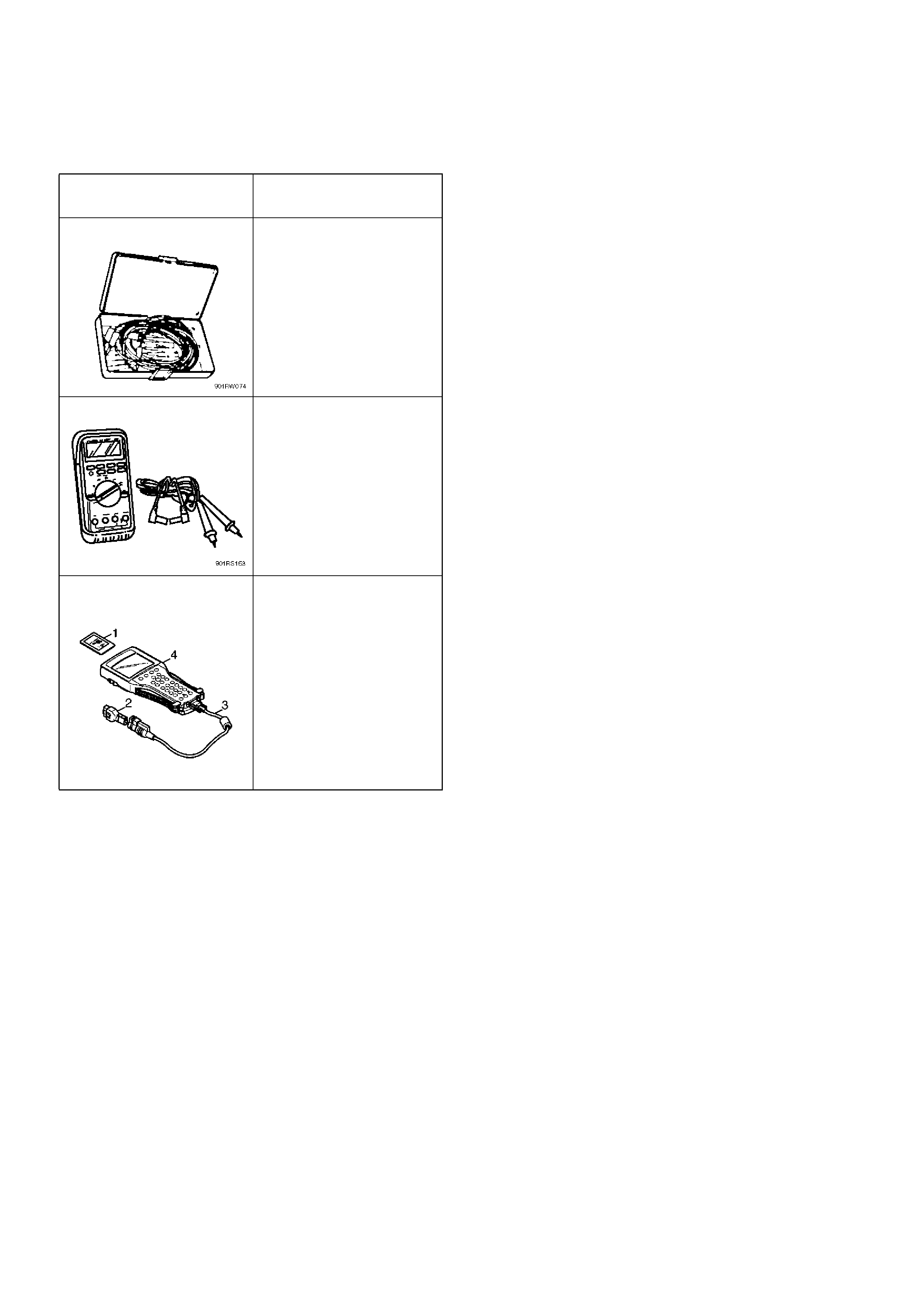
Special Tools
ILLUSTRATION TOOL NO.
TOOL NAME
5–8840–0385–0
(J–35616)
Connector test adapter kit
5–8840–0366–0
(J–39200)
High impedance
multimeter
7000086–ISU
Tech 2 Set
(1) PCMCI A Car d
(2) SAE 16/19 Adapter
(3) DLC Cable
(4) Tech 2