
SECTION 0A - GENERAL INFORMATION
General Repair Instruction
Illustration Arrows
Identification
Lifting Instructions
Standard Bolts Torque Specifications
Abbreviations Charts
GENERAL REPAIR INSTRUCTION
1. If a floor jack is used, the following precautions are
recommended.
Park vehicle on level ground, “block" front or rear
wheels, set jack against the recommended lifting
points (see “Lifting Instructions" in this section),
raise vehicle and support with chassis stands and
then perform the service operations.
2. Before performing service operations, disconnect
ground cable from the battery to reduce the chance
of cable damage and burning due to short circuiting.
3. Use a cover on body, seats and floor to protect them
against damage and contamination.
4. Brake fluid and anti–freeze solution must be
handled with reasonable care, as they can cause
paint damage.
5. The use of proper tools and recommended essential
and available tools, where specified, is important
for efficient and reliable performance of service
repairs.
6. Use genuine Isuzu parts.
7. Used cotter pins, plastic clips, gaskets, O–rings, oil
seals, lock washers and self–locking nuts should be
discarded and new ones should be installed, as
normal function of the parts cannot be maintained if
these parts are reused.
8. To facilitate proper and smooth reassembly
operation, keep disassembled parts neatly in
groups. Keeping fixing bolts and nuts separate is
very important, as they vary in hardness and design
depending on position of installation.
9. Clean the parts before inspection or reassembly.
Also clean oil ports, etc. using compressed air, and
make certain they are free from restrictions.
10. Lubricate rotating and sliding faces of the parts with
oil or grease before installation.
11. When necessary, use a sealer on gaskets to
prevent leakage.
12. Carefully observe all specifications for bolt and nut
torques.
13. When removing or replacing parts that require
refrigerant to be discharged from the air
conditioning system, be sure to use the Vehicle
Refrigerant Recovery and Recycling Equipment
(VRRRE) to recover and recycle Refrigerant–134a.
14. When a service operation is completed, make a final
check to be sure the service has been done
properly and the problem has been corrected.
15. SUPPLEMENTAL RESTRAINT SYSTEM
The vehicle is equipped with a Supplemental
Restraint System (SRS) – Air Bags. This system is
not to be serviced without consulting the appropriate
service information. Consult Section 9J “SRS
System" if work is to be done on the front of the
vehicle such as bumper, sheet metal, seats, wiring,
steering wheel or column. Also review SRS system
information if any arc welding is to be done on the
vehicle. The SRS system equipped vehicle can be
identified by:
1. “AIR BAG" warning light on the instrument
cluster.
2. “SRS” embossed on the steering wheel horn
pad.
3. SRS warning labeling on the interior sunvisor.
Techline
Techline
Techline
Techline
Techline
Techline
Techline
Techline
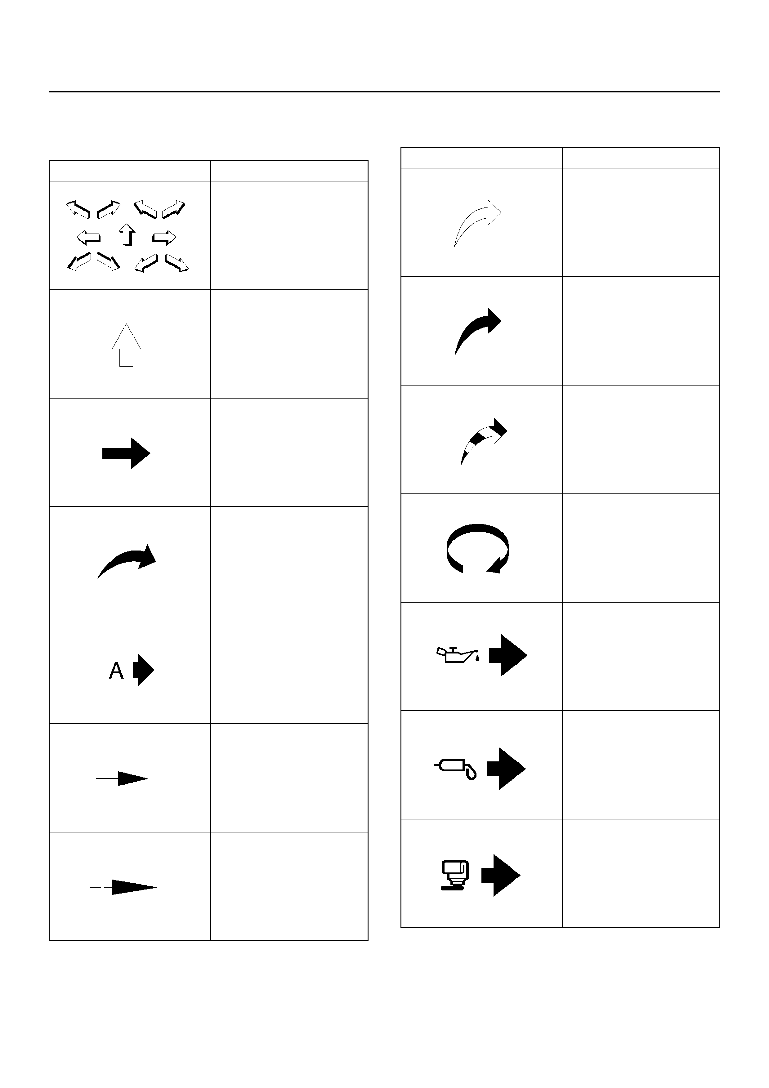
ILLUSTRATION ARROWS
Arrows are designed for specific purposes to aid your understanding of technical illustrations.
Arrow Type Application
Front of vehicle
Up Side
Task Related
Vie w De ta il
View A n gle
Dimension (1:2)
Sectioning (1:3)
• Ambient/Clean air flow
• Cool air flow
• Gas other than
ambient air
• Hot air flow
• Ambient air mixed with
another gas
• Can indicate
temperature change
Motion or direction
Lubrication point oil or
fluid
Lubrication point grease
Lubrication point jelly
Arrow Type Application
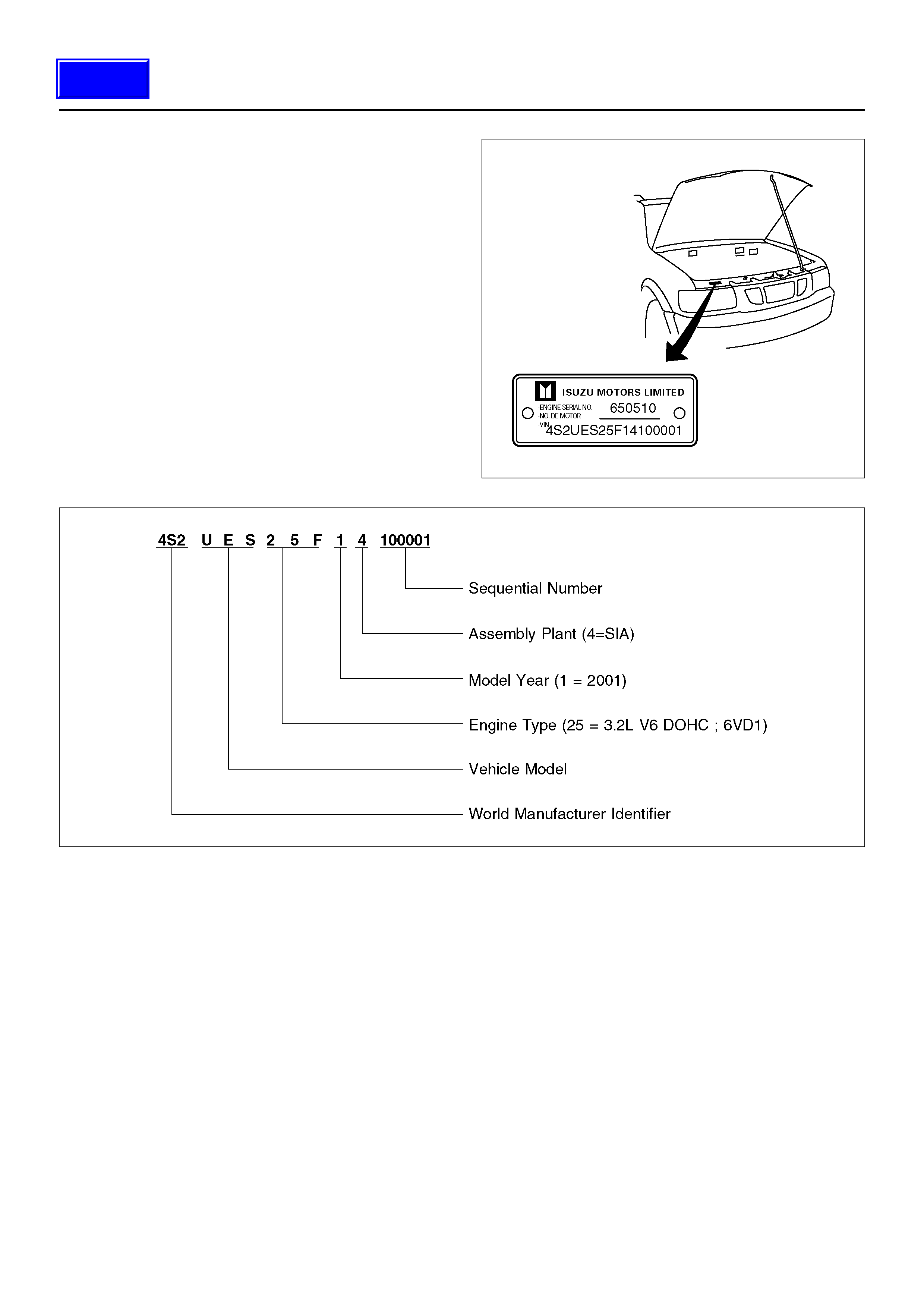
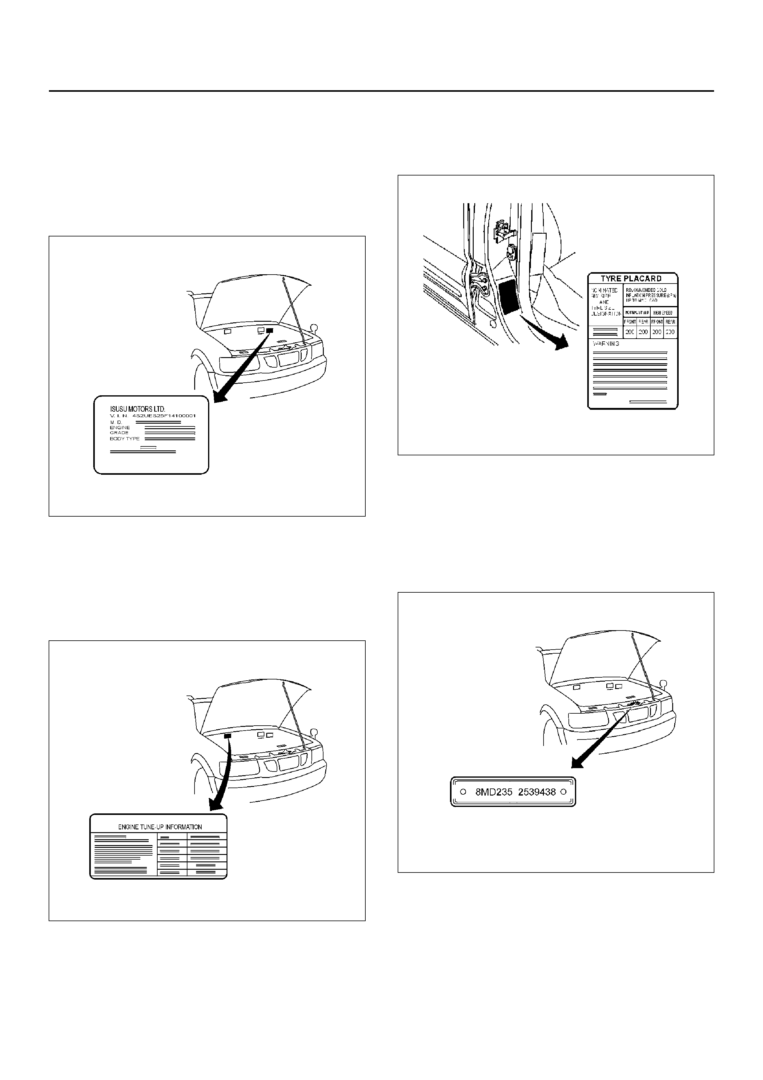
Body and Options Plate
The Body and Options plate is located on the passenger
side of the dash panel in the engine compartment.
It displays the VIN and codes for options that have been
built into the vehicle. Forr example, the body type, body
paint colour, trim level, engine and transmission codes
and model designation.
Emission Label
The Emission label is located on the driver’s side of the
dash panel in the engine compartment.
It shows the relevant tune-up information required to
maintain the minimum exhaust emissions.
Tyre Placard
The Tyre Placard is located on the driver’s door lock
pillar, and is visible when the door is open.
Holden Identification Plate
The Holden identification Plate is riveted to the centre of
the radiator support panel in the engine compartment
It is used for warranty identification, roadside assistance
identi ficati on etc .
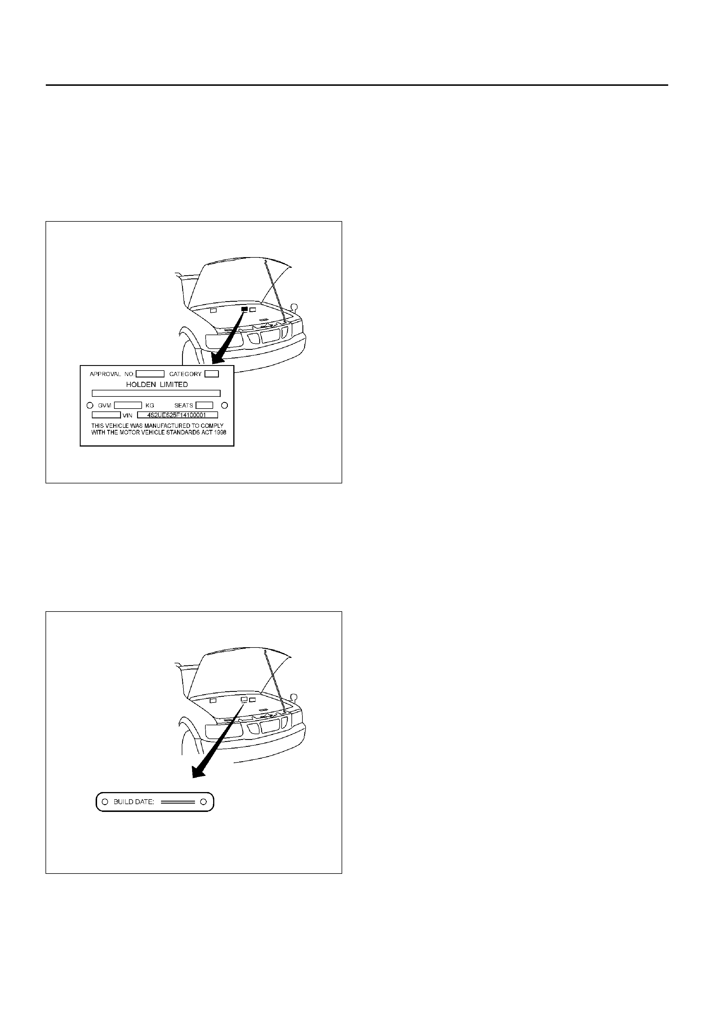
Safety Compliance (ADR) Plate
The ADR plate is riveted to the passenger side of the
dash panel in the engine compartment.
It displays the approval numbers, category,
manufacturers name, model name and code, Gross
Vehicle Mass (GVM), seating capacity, build date and
VIN.
Build Date Plate
The Build Date Plate is riveted to the passenger side of
the dash panel in the engine compartment, below the
Safety Compliance Plate.
It displays the date upon which the vehicle was built.
F00R100001
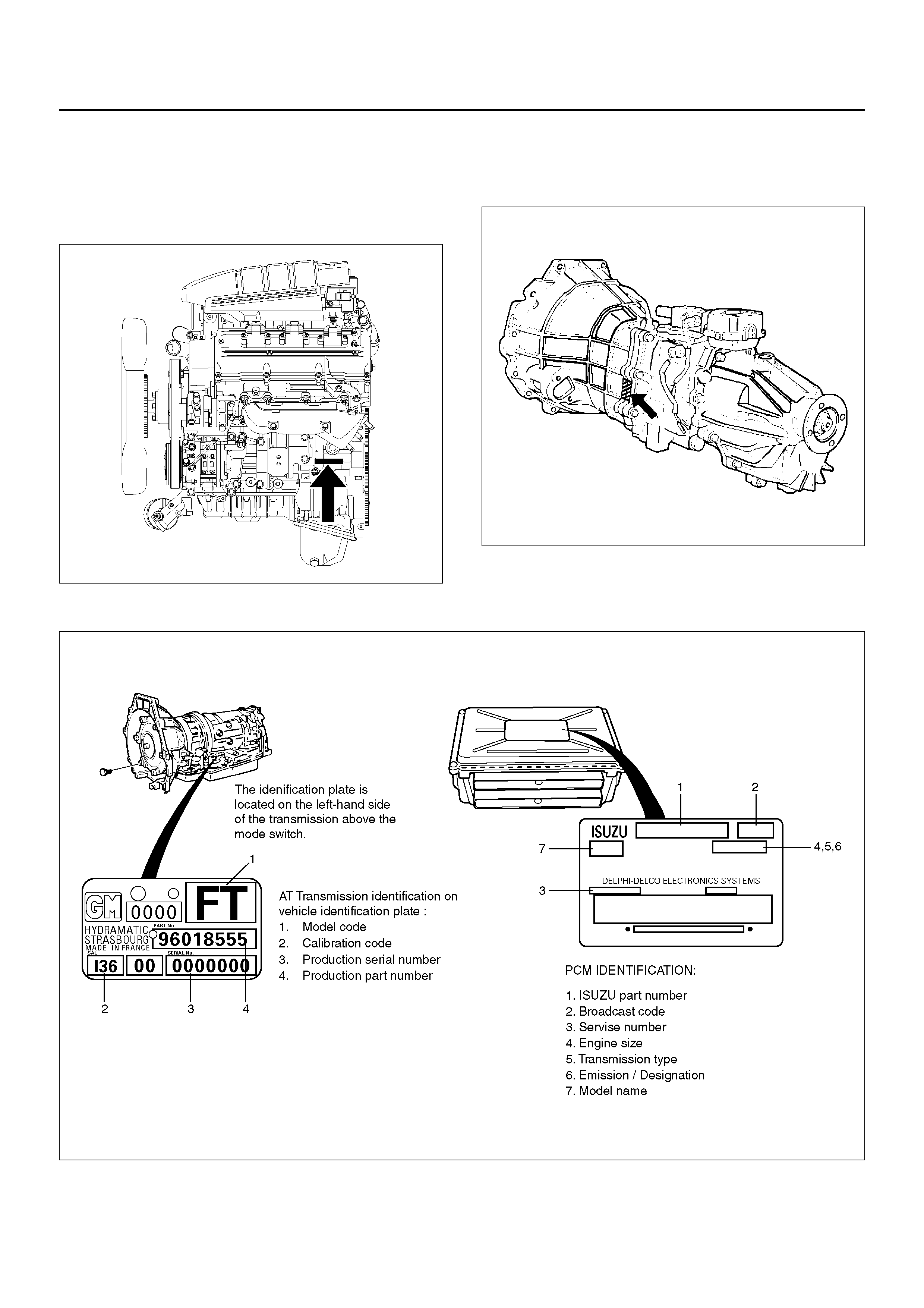
Engine Serial Number
• 6VD1 Engine
The gasoline engine serial number is stamped on the
left rear lower area of the cylinder block above the
starter.
F00R100002
Transmission Se rial Number
Manual : Stamped on the left side of the transmission
intermediate plate.
220RS025
Automatic : Stamped on the identification plate, located
on the left side of the transmission above the mode
switch.
F00R100003
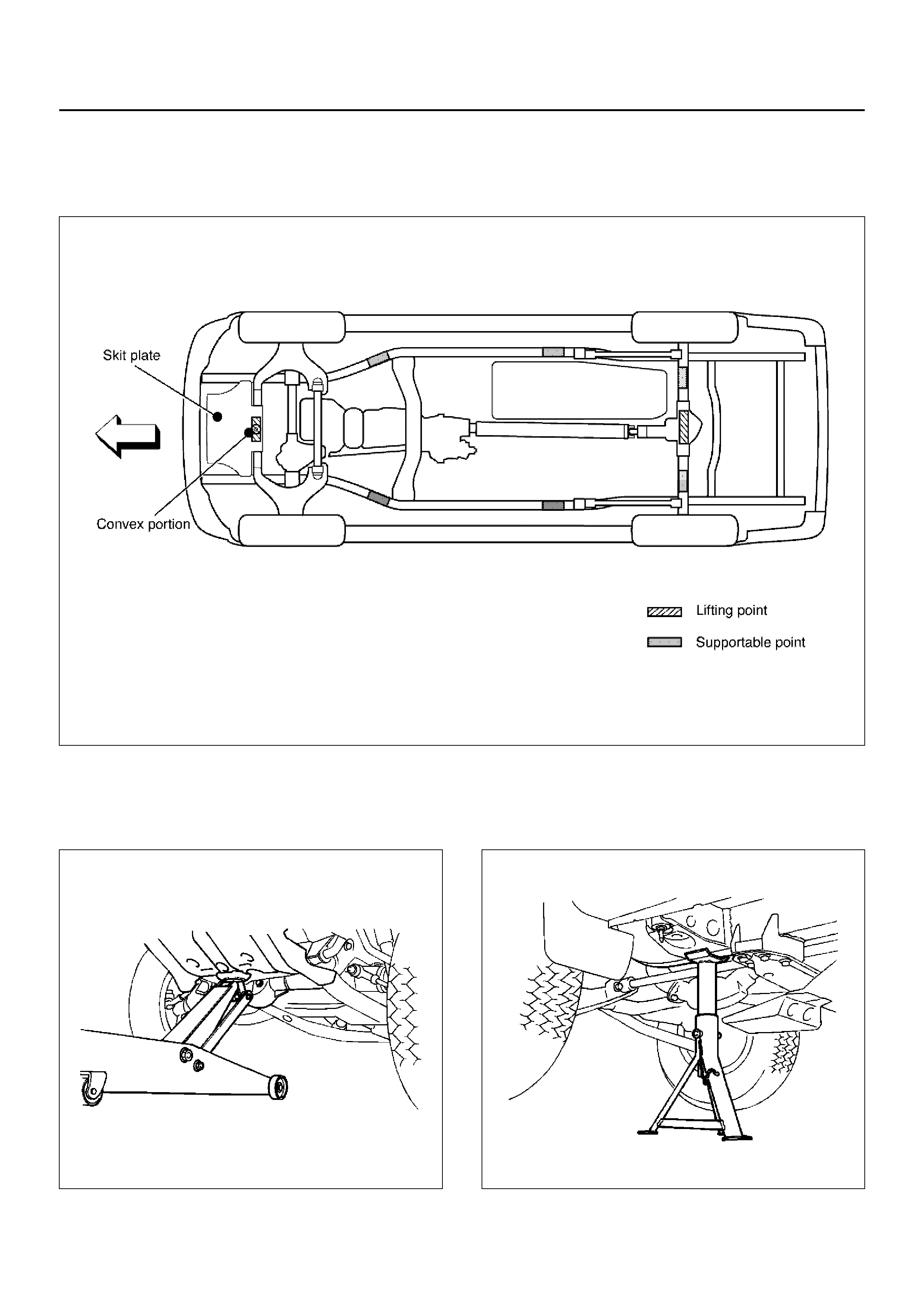
LIFTING INSTRUCTIONS
Lifting Points and Supporta ble Point Locations
4 Door Model
C00RX002
Lifting Point: Front
• When using a floor jack, lift on the Convex portion of
the skid plate.
545RS001
Supportable Point: Front
• Position the chassis stands at the bottom of the frame
sidemember, behind the front wheel.
501RS003
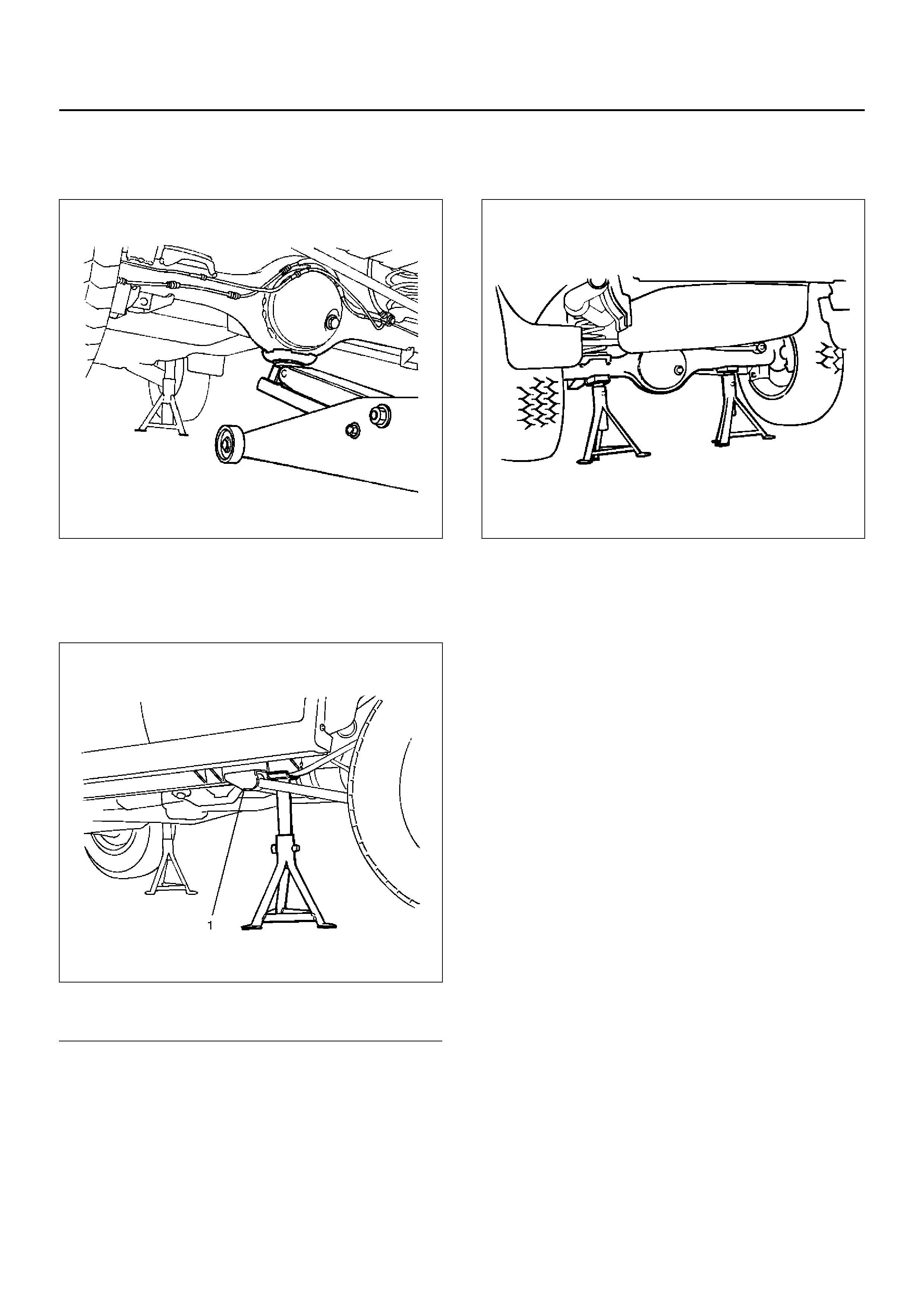
Lifting Point: Rear
• Position the floor jack at the center of the rear axle
case when lifting the vehicle.
420RS002
Supportable Point: Rear
• Position the chassis stands at the bottom of the frame
sidemember, just behind the trailing link bracket.
501RW002
Legend
EndOFCallout
Supportable Point: Rear
• Position the chassis stands at the bottom of the rear
axle case.
420RS001
(1) Trailing Link Bracket

STANDARD BOLTS TORQUE SPECIFICATIONS
The torque values given in the following table should be
applied where a particular torque is not specified.
The asterisk * indicates that the bolts are used for
female–threaded parts that are made of soft materials
such as casting, etc.
Strength Class 4.8 8.8 9.8
Refined Non-Refined
Bolt
Identification
Bolt Diameter ×
Pitch (mm)
M 6X1.0
M 8X1.25
M 10X1.25
* M10X1.5
M12X1.25
* M12X1.75
M14X1.5
* M14X2.0
M16X1.5
* M16X2.0
M18X1.5
M20X1.5
M22X1.5
M24X2.0
4 – 8 N·m (3 – 6 lb ft)
8 – 18 N·m (6 – 13 lb ft)
21 – 34 N·m (15 – 25 lb ft)
20 – 33 N·m (14 – 25 lb ft)
49 – 74 N·m (36 – 54 lb ft)
45 – 69 N·m (33 – 51 lb ft)
77 – 115 N·m (56 – 85 lb ft)
72 – 107 N·m (53 – 79 lb ft)
104 – 157 N·m (77 – 116 lb ft)
100 – 149 N·m (74 – 110 lb ft)
151 – 226 N·m (111 – 166 lb ft)
206 – 310 N·m (152 – 229 lb ft)
251 – 414 N·m (185 – 305 lb ft)
359 – 539 N·m (265 – 398 lb ft)
5 – 10 N·m (4 – 7 lb ft)
12 – 23 N·m (9 – 17 lb ft)
28 – 46 N·m (20 – 34 lb ft)
28 – 45 N·m (20 – 33 lb ft)
61 – 91 N·m (45 – 67 lb ft)
57 – 84 N·m (42 – 62 lb ft)
93 – 139 N·m (69 – 103 lb ft)
88 – 131 N·m (65 – 97 lb ft)
135 – 204 N·m (100 – 150 lb ft)
130 – 194 N·m (95 – 143 lb ft)
195 – 293 N·m (144 – 216 lb ft)
270 – 405 N·m (199 – 299 lb ft)
363 – 544 N·m (268 – 401 lb ft)
431 – 711 N·m (318 – 524 lb ft)
–
17 – 30 N·m (12 – 22 lb ft)
37 – 63 N·m (27 – 46 lb ft)
36 – 60 N·m (27 – 44 lb ft)
76 – 114 N·m (56 – 84 lb ft)
72 – 107 N·m (53 – 79 lb ft)
114 – 171 N·m (84 – 126 lb ft)
107 – 160 N·m (79 – 118 lb ft)
160 – 240 N·m (118 – 177 lb ft)
153 – 230 N·m (113 – 169 lb ft)
230 – 345 N·m (169 – 255 lb ft)
317 – 476 N·m (234 – 351 lb ft)
425 – 637 N·m (313 – 469 lb ft)
554 – 831 N·m (409 – 613 lb ft)

ABBREVIATIONS CHARTS
List of automotive abbreviations which may be used
in this manual
A — Ampere(s)
ABS — Antilock Brake System
AC — Alternating Current
A/C — Air Conditioning
ACCEL — Accelerator
ACC — Accessory
ACL — Air Cleaner
Adj — Adjust
A/F — Air Fuel Ratio
AIR — Secondary Air Injection System
Alt — Altitude
AMP — Ampere(s)
ANT — Antenna
ASM — Assembly
A/T — Automatic Transmission/Transaxle
ATDC — After Top Dead Center
ATF — Automatic Transmission Fluid
Auth — Authority
Auto — Automatic
BARO — Barometric Pressure
Bat — Battery
B+ — Battery Positive Voltage
Bbl — Barrel
BHP — Brake Horsepower
BPT — Backpressure Transducer
BTDC — Before Top Dead Center
° C — Degrees Celsius
CAC — Charge Air Cooler
Calif — California
cc — Cubic Centime ter
CID — Cubic Inch Displacement
CKP — Crankshaft Position
CL — Closed Loop
CLCC — Closed Loop Carburetor Control
CMP — Camshaft Position
CO — Carbon Monoxide
Coax — Coaxial
Conn — Connector
Conv — Converter
Crank — Crankshaft
Cu. In. — Cubic Inch
CV — Constant Velocity
Cyl — Cylinder(s)
DI — Distributor Ignition
Diff — Differential
Dist — Distributor
DLC — Data Link Connector
DOHC — Double Overhead Camshaft
DTC — Diagnostic Trouble Code
DTM — Diagnostic Test Mode
DTT — Diagnostic Test Terminal
DVM — Digital Voltmeter (10 meg.)
DVOM — Digital Volt Ohmmeter
EBCM — Electronic Brake Control Module
ECM — Engine Control Module
ECT — Engine Coolant Temperature
EEPROM — Electronically Erasable Programmable
Read Only Memory
EGR — Exhau st Ga s Rec irc ula tion
EI — Electronic Ignition
ETR — Electronically Tuned Receiver
EVAP — Evaporation Emission
Exh — Exhaust
° F — Degrees Fahrenheit
Fed — Federal (All States Exce pt Cali f.)
FF — Front Drive Front Engine
FL — Fusible Link
FLW — Fusible Link Wire
FP — Fuel Pump
FRT — Front
ft — Foot
FWD — Front Wheel Drive
4WD — Four Wheel Dr ive
4 x 4 — Four Wheel Drive
4 A/T — Four Speed Automatic Transmission/Transaxle
Gal — Gallon
GEN — Generator
GND — Ground
Gov — Governor
g — Gram
Harn — Harness
HC — Hydrocarbons
HD — Heavy Duty
Hg — Hydrargyrum (Mercury)
HiAlt — High Altitude
HO2S — Heated Oxygen Sensor
HVAC — Heater–Vent–Air–Conditioning
IAC — Idle Air Control
IAT — Intake Air Temperature
IC — Integrated Circuit / Ignition Control
ID — Identification / Inside Diameter
IGN — Ignition
INJ — Injection
IP — Instrument Panel
IPC — Instrument Panel Cluster
Int — Intake
ISC — Idle Speed Control
J/B — Junction Block
kg — Kilogram s
km — Kilometers
km/h — Kilo meter per Hour
kpa — Kilopascals
kV — Kilovolts (thousands of volts)
kW — Kilowatts
KS — Knock Sensor
L — Li ter
lb ft — Foot Pounds
lb in — Inch Pounds
LF — Left Front
LH — Left Hand
LR — Left Rear
LS — Left Side
LWB — Long Wheel Base
L–4 — In–Line Four Cylinder Engine
MAF — Mass Air Flow
MAN — Manual

MAP — Manifold Absolute Pressure
Max — Maximum
MC — Mixture Control
MFI — Multiport Fuel Injection
MIL — Malfunction Indicator Lamp
Min — Minimum
mm — Millimete r
MPG — Miles Per Gallon
MPH — Miles Per Hour
M/T — Manual Transmission/Transaxle
MV — Millivolt
N — Newtons
NA — Natural Aspirated
NC — Normally Closed
N·M — Newton Meters
NO — Normally Open
NOX — Nitrogen, Oxides of
OBD — On-Board Diagnostic
OD — Outside Diameter
O/D — Over Drive
OHC — Overhead Camshaft
OL — Open Loop
O2 — Oxygen
O2S — Oxygen Sensor
PAIR — Pulsed Secondary Air Injection System
P/B — Power Brakes
PCM — Powertrain Control Module
PCV — Positive Crankcase Ventilation
PRESS — Pressure
PROM — Programmable Read Only Memory
PNP — Park/Neutr al Pos ition
P/S — Power Steering
PSI — Pounds per Square Inch
PSP — Power Steering Pressure
Pt. — Pint
Pri — Primary
PWM — Pulse Width Modulate
Qt. — Quart
REF — Reference
RF — Right Front
RFI — Radio Frequency Interference
RH — Right Hand
RPM — Revolutions Per Minute
RPM Sensor — Engine Speed Sensor
RPO — Regular Production Option
RR — Right Rear
RS — Right Side
RTV — Room Temperature Vulcanizing
RWAL — Rear Wheel Antilock Brake
RWD — Rear Wheel Drive
SAE — Society of Automotive Engineers
Sec — Secondary
SFI — Sequential Multiport Fuel Injection
SI — System International
SIR — Supplemental Inflatable Restraint System
SOHC — Single Overhead Camshaft
Sol — Solenoid
SPEC — Specif ic ati on
Speedo — Speedometer
SRS — Supplemental Restraint System
ST — Start / Scan Tool
Sw — Switch
SWB — Short Wheel Base
SYN — Synchronize
Tach — Tachometer
TB — Throttle Body
TBI — Throttle Body Fuel Injection
TCC — Torque Converter Clutch
TCM — Transmission Control Module
TDC — Top Dead Center
Term — Terminal
TEMP — Temperature
TOD— Torque On Demand
TP — Throttle Position
TRANS — Transmission/Transaxle
TURBO — Turbocharger
TVRS — Televisi on & Radio Suppression
TVV — Thermal Vacuum Valve
TWC — Three Way Catalytic Converter
3 A/T — Three Speed Automatic Transmission/
Transaxle
2WD — Two Wheel Drive
4 x 2 — Two Wheel Drive
U–joint — Universal Joint
V — Volt(s)
VAC — Vacuum
VIN — Vehicle Identification Number
VRRRE — Vehicle Refrigerant Recovery and Recycling
Equipment
V–ref — ECM Reference Voltage
VSS — Vehicle Speed Sensor
VSV — Vacuum Switch Valve
V–6 — Six Cylinder “V" Engine
V–8 — Eight Cylinder "V" Engine
W — Watt(s)
w/ — With
w/b — Wheel Base
w/o — Without
WOT — Wide Open Thrott le