
SECTION 1A1 - BODY STRUCTURE
Service Precaution
Frame
General Description
Frame Dimensions
General Description (Bumper)
Front Bumper
Parts Location
Removal
Installation
Front Bumper Slider Bracket
Removal
Installation
Rear Bum
Parts Location
per
Removal
Installation
Rear Bumper Slider
Removal
Installation
General Description (Sheet Metal)
Engine Hood
Parts Location
Removal
Installation
Engine Hood Lock
Parts Location
Removal
Installation
Radiator Grille
Parts Location
Removal
Installation
Front Fender Panel
Parts Location
Removal
Installation
Body Mounting
Parts Location
Tightening Torque
Body Dimension
Front Section
Room Section (Front Side)
Room Section (Rear Side)
Rear Section
Side Body Section (Front side)
Side Body Section (Rear side)
General Description (Body)
Instrument Panel Assembly
Parts Location
Removal
Installation
Front Door Assembly
Parts Location
Removal
Installation
Rear Door Assembly
Parts Location
Removal
Installation
Front Window Regulator, Glass
and Glass Run
Parts Location
Removal
Installation
Rear Window Regulator, Glass
and Glass Run
Parts Location
Removal
Installation
Tailgate
Parts Location
Removal
Installation
Rear Hatchgate
Parts Location
Removal
Installation
Adjustment
Spare Tire Carrier
Parts Location
Removal
Installation
Windshield
Parts Location
Removal
Installation
Rear Quarter Glass
Parts Location
Removal
Installation
Main Data and Specifications
Special Tools

SERVICE PRECAUTION
WARNING: THIS VEHICLE HAS A SUPPLEMENTAL
RESTRAINT SYSTEM (SRS). REFER TO THE SRS
COMPONENT AND WIRING LOCATION VIEW IN
ORDER TO DETERMINE WHETHER YOU ARE
PERFORMING SERVICE ON OR NEAR THE SRS
COMPONENTS OR THE SRS WIRING. WHEN YOU
ARE PERFORMING SERVICE ON OR NEAR THE
SRS COMPONENTS OR THE SRS WIRING, REFER
TO THE SRS SERVICE INFORMATION. FAILURE TO
FOLLOW WARNINGS COULD RESULT IN POSSIBLE
AIR BAG DEPLOYMENT, PERSONAL INJURY, OR
OTHERWISE UNNEEDED SRS SYSTEM REPAIRS.
CAUTION: Always use the correct fastener in the
proper location. When you replace a fastener, use
ONLY the exact part number for that application.
HOLDEN will call out those fasteners that require a
replacement after removal. HOLDEN will also call
out the fasteners that require thread lockers or
thread sealant. UNLESS OTHERWISE SPECIFIED,
do not use supplemental coatings (Paints, greases,
or other corrosion inhibitors) on threaded fasteners
or fastener joint interfaces. Generally, such
coatings adversely affect the fastener torque and
the joint clamping force, and may damage the
fastener. When you install fasteners, use the correct
tightening sequence and specifications. Following
these instructions can help you avoid damage to
parts and systems.
FRAME
GENERAL DESCRIPTION
Proper frame alignment is important to assure normal
vehicle life and performance of many other parts of the
vehicle. If the vehicle has been involved in a fire,
collision or has been overloaded, it is necessary to
check the frame alignment.
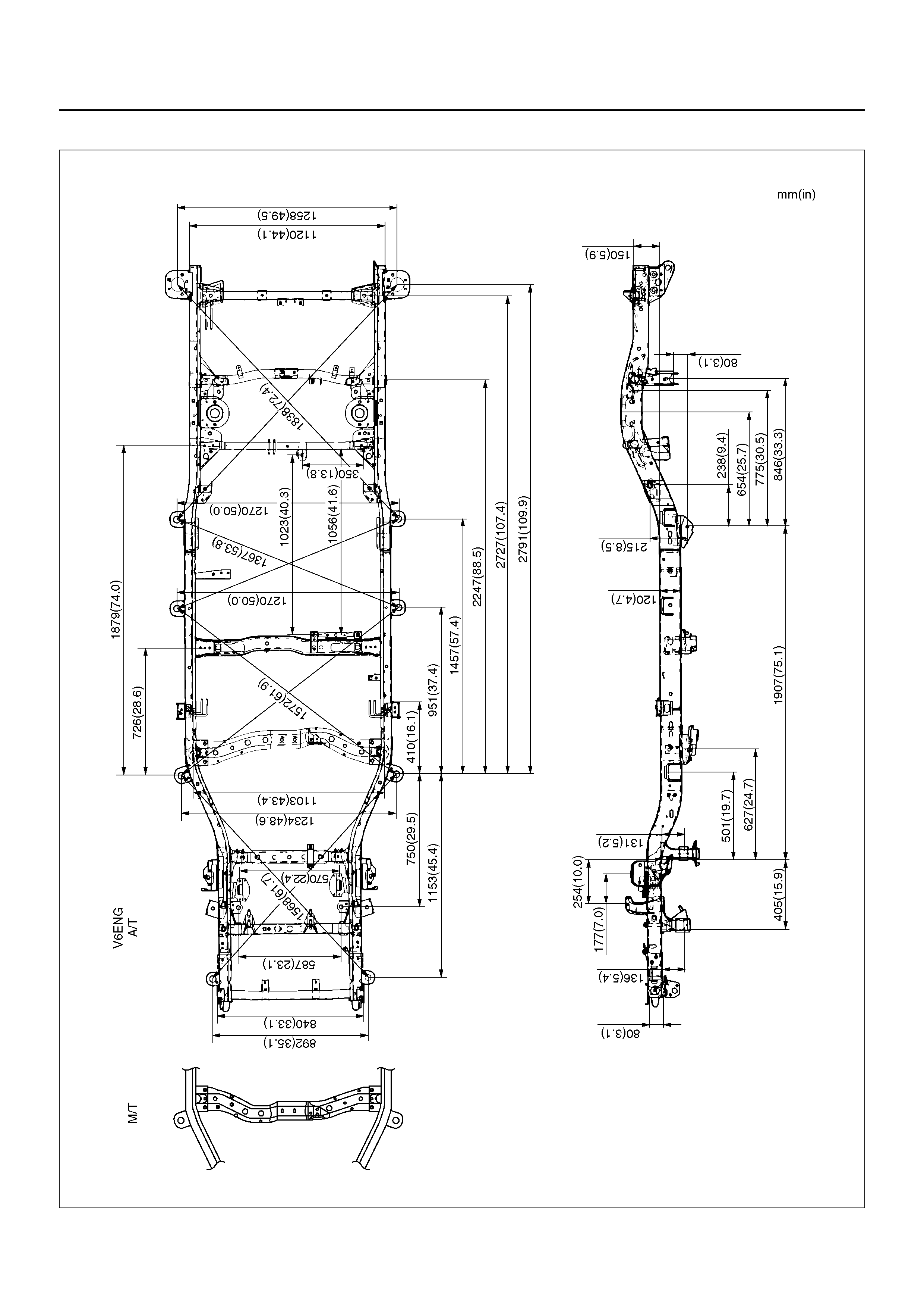
FRAME DIMENSIONS
501R100006
GENERAL DESCRIPTION (BUMPER)
Front and rear bumpers consist of bumper fascia,
support, and reinforcement. The absorbing capability for both front and rear bumper
systems are achieved through reinforcements in each
bumper.
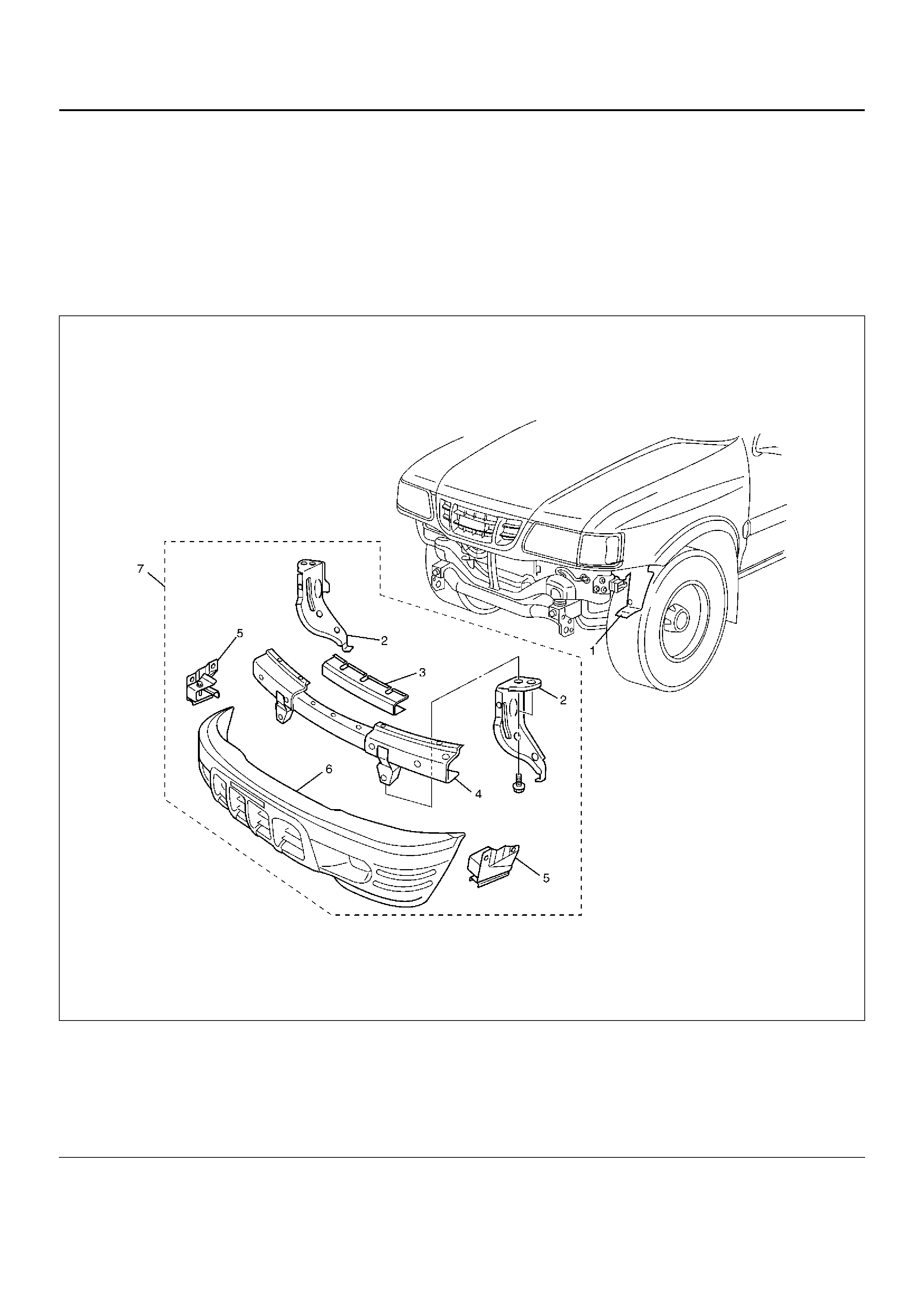
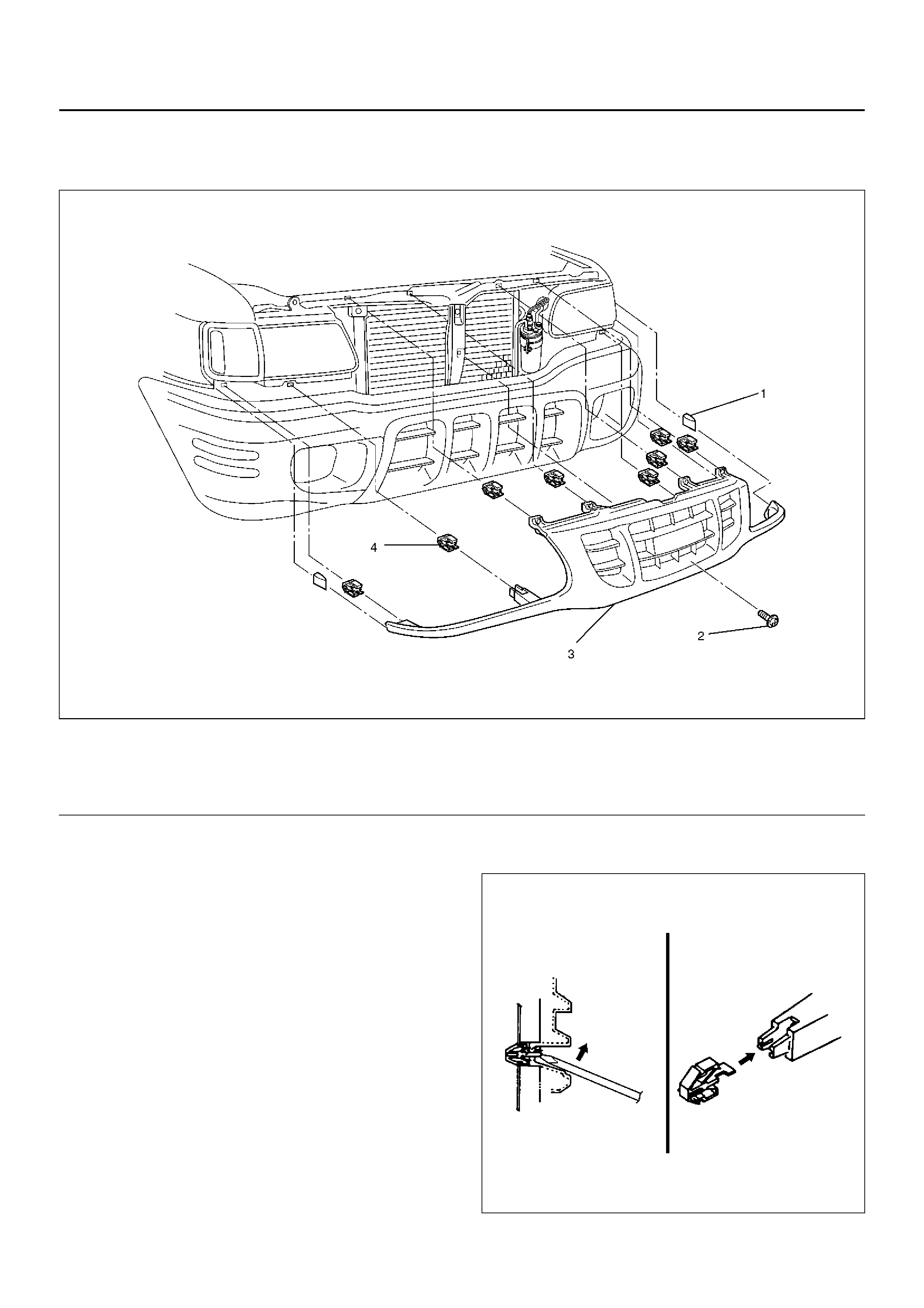
FRONT BUMPER
PARTS LOCATION
601RY00010
Legend
EndOFCallout
(1) Inner Liner
(2) Backbar
(3) Support Assembly
(4) Front Bumper Reinforcement Assembly
(5) Front Bumper Slide r
(6) Fr ont Bum per Fa scia
(7) Fr ont Bum per As se mbl y
REMOVAL
1. Disconnect the battery ground cable.
2. Disconnect front fog light connector (With fog light).
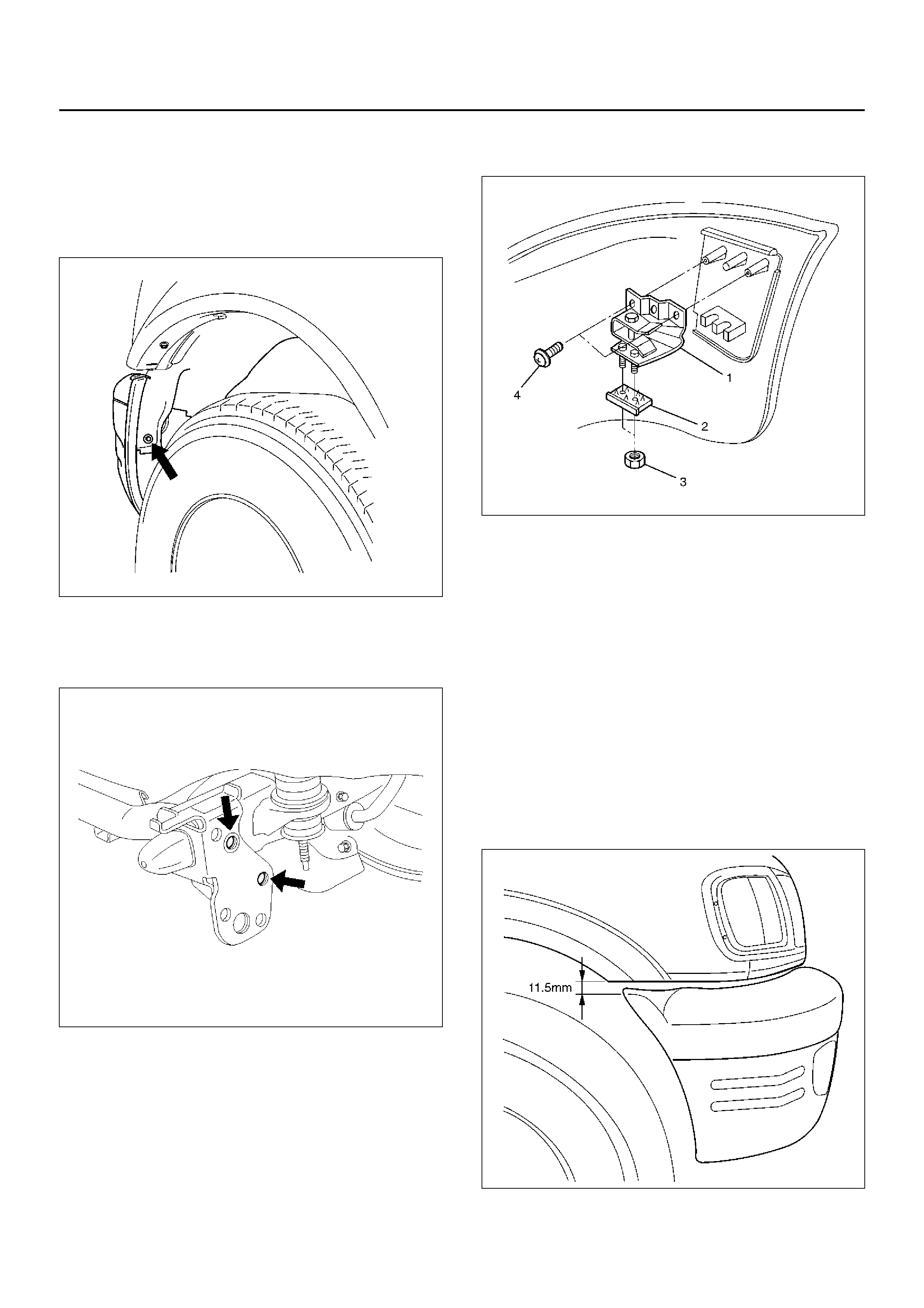
3. Remove the inner liner fixing clip on the back side of
the front bumper.
647RY00002
4. Remove the front bumper fixing bolts.
• Remove the two bolts from both sides of the front
bumper.
601RW004
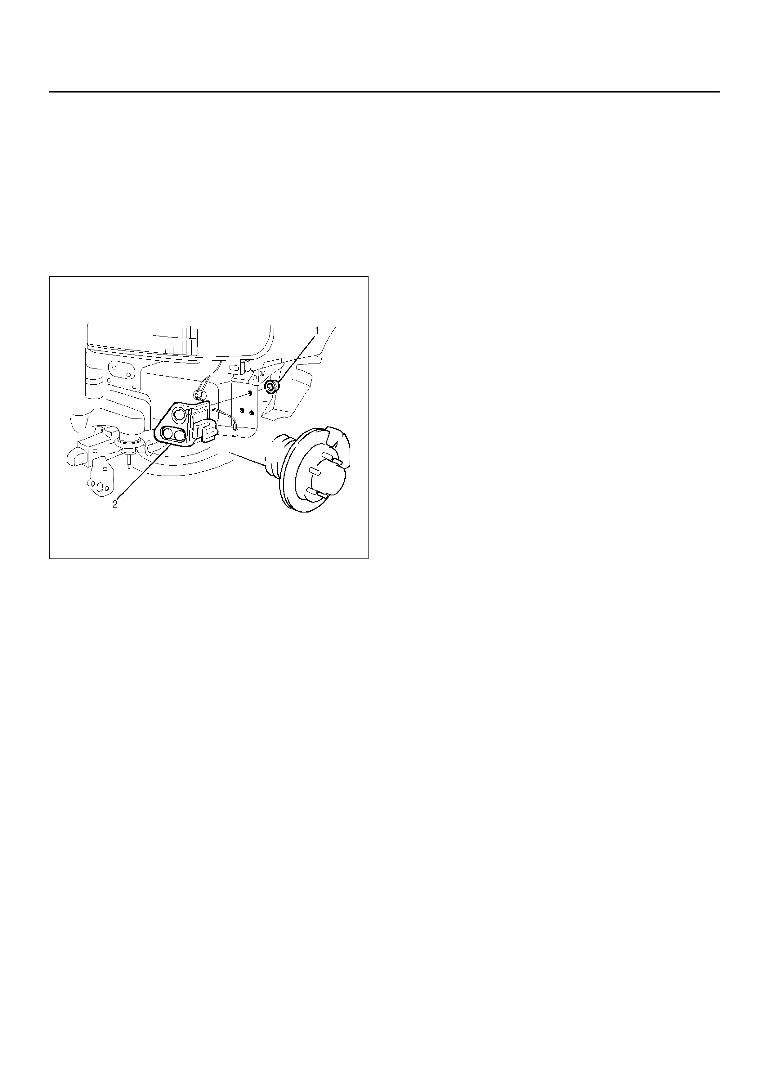
5. Remove the front bumper assembly.
6. Remove the support assembly.
• Remove the three fixing bolts.
7. Remove the front bumper reinforcement assembly.
• Remove the eleven fixing bolts.
8. Remove the three bolts at each backbar and
remove backbars.
9. Remove the front fog light assembly (With fog light).
10. Remove the front bumper slider(1).
• Remove the two screws(4) and the two nuts(3),
and release the claw from the washer(2).
601RY00004
INSTALLATION
To install, follow the removal steps in reverse order
noting the foll owi ng poi nts:
1. T ighten the front bumper assembly fixing bolts to the
specified torque.
Torque : 147 N·m (15 kg·m/108 lb ft)
2. Front bumper adjustment
• When the bolts fixing front bumper assembly are
tightened, adjustment should be made between
the back bar and front side bumper so that a
clearance of 11.5 mm is provided between the
lower side of the fender and the upper side of the
front bumper.
601RY00013
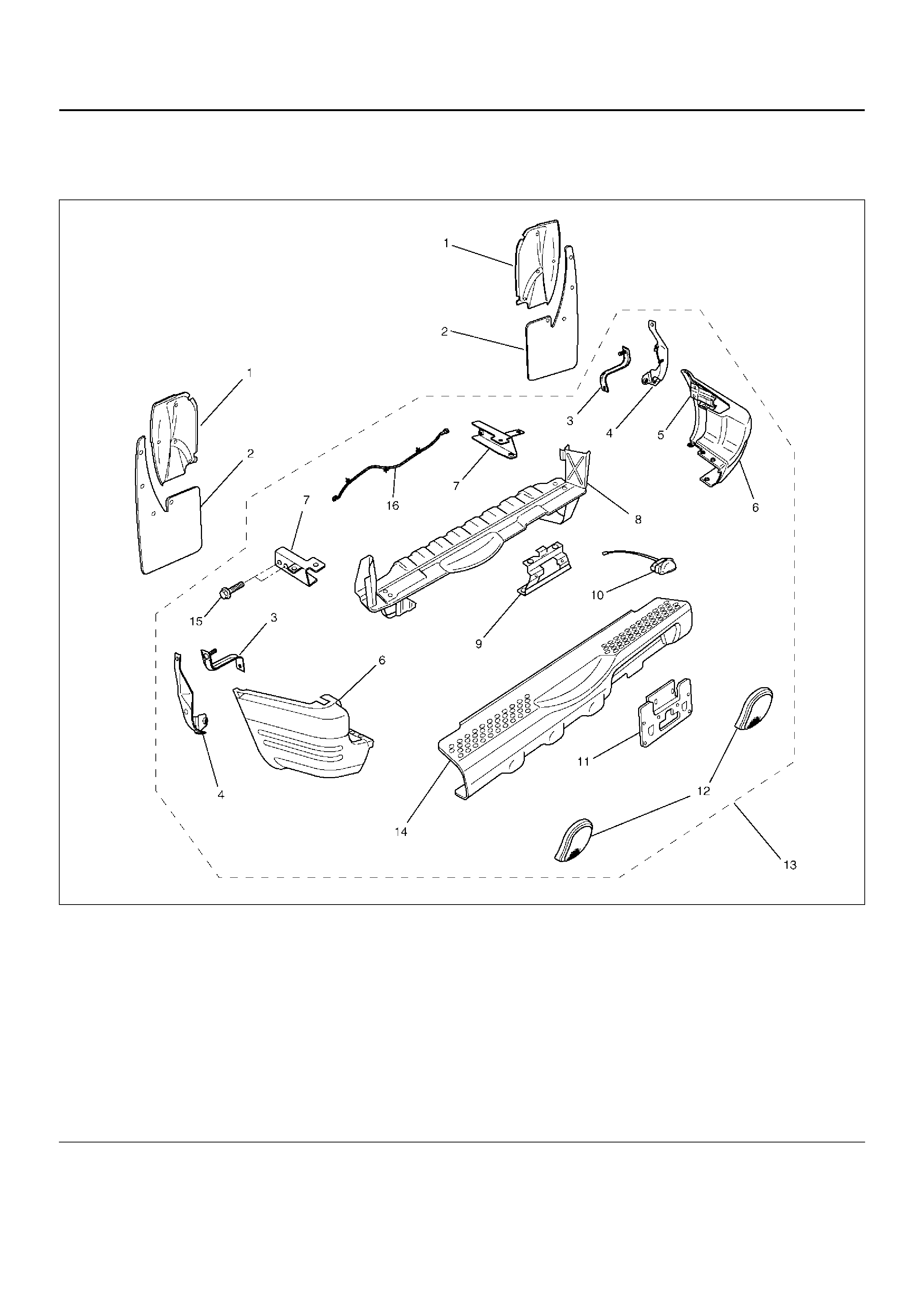
REAR BUMPER
PARTS LOCATION
690RY00012
Legend
EndOFCallout
(1) Protector
(2) Rear Mud Flap
(3) Bumper Bracket
(4) Rear Bumper Support
(5) Rear Bumper Slider Bracket
(6) Rear Corner Bumper
(7) Backber
(8) Rear Bumper Reinforcement Ass embly
(9) Rear License Plate Bracket
(10) License Plate Light Assembly
(11) Rear License Plat e Extension
(12) Reflector Assembly
(13) Rear Bumper Assembly
(14) Rear Center Bumper
(15) Rear Bumper Fixing Bolt
(16) License Plate Light Harness
REMOVAL
1. Disconnect the battery ground cable.
2. Remove the rear mud flaps.
• Remove the four bolts.
3. Remove the protectors.
• Remove the three clips on the right side and five
clips on the left side.
4. Remove the bumper brackets.
• Remove the two nuts.
5. Remove the rear bumper supports.
• Remove the nut and bolt.
6. Remove the rear bumper assembly(1).
• Remove the two bolts(2) from each side.
• Disconnect the license plate light harness
connector.
• Open the tailgate in an angle of 60° to avoid the
interference with the spare tire.
690RY00002
7. Remove the license plate light assembly and
license plate harness.
8. Remove the rear license plate extension and
bracket.
9. Remove the rear center bumper.
• Remove the ten clips from the step part and three
bolts from each upper and lower sides.
10. Remove the reflector assemblies.
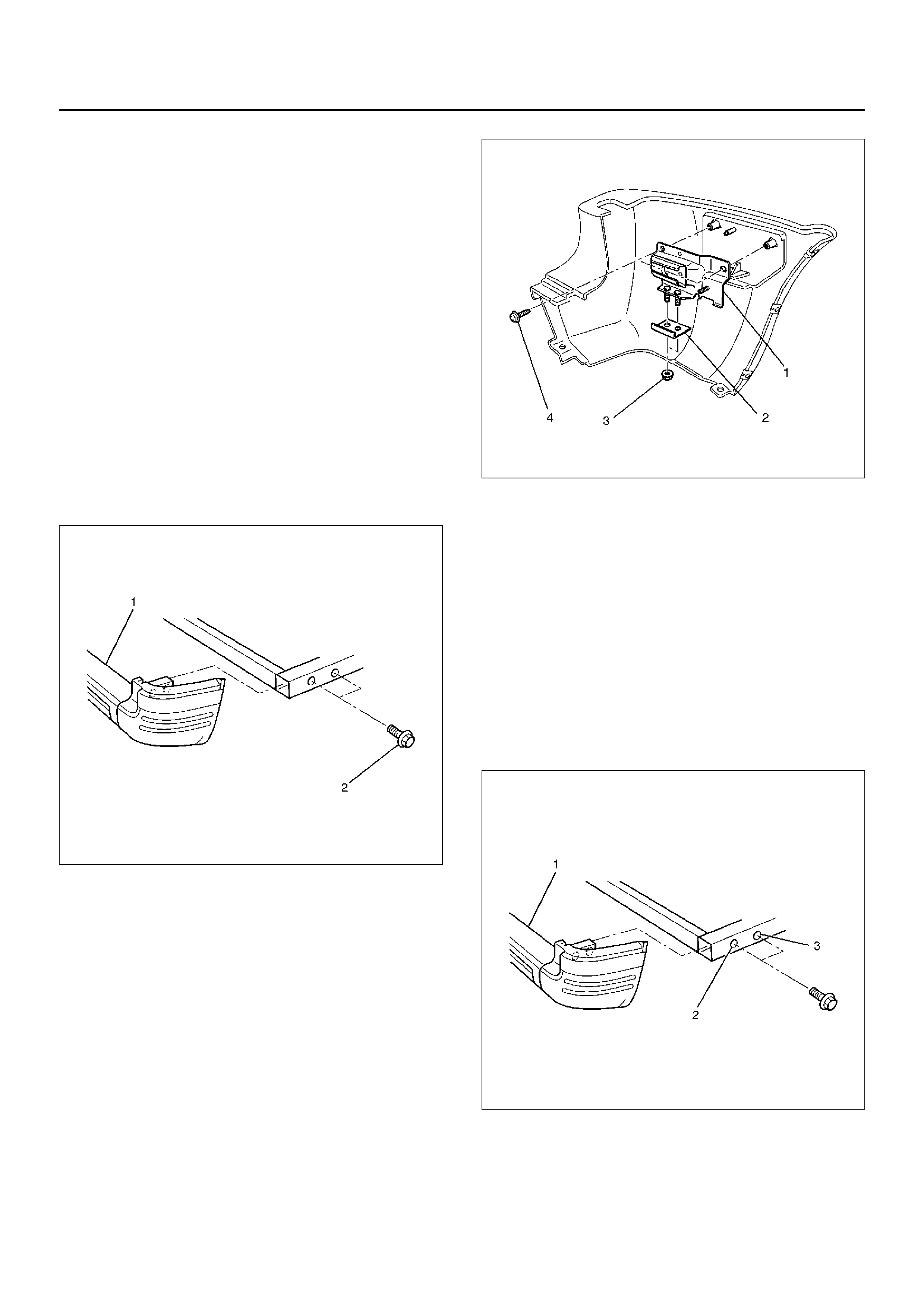
11. Remove the rear corner bumpers.
• Remove the three bolts from each rear corner
bumper.
12. Remove the rear bumper slider brackets(1).
• Remove the two screws(4) and two nuts(3), and
then remove claw caught in the washer(2).
690RY00010
13. Remove the backbers from the rear bumper
reinforcement assembly.
• Remove the three bolts at each backber.
INSTALLATION
To install, follow the removal steps in reverse order,
noting the foll owi ng poi nts:
1. Partially tighten the rear bumper bolts(2) (3) and
adjust the clearance between the body (tailgate)
and the rear bumper(1).
Then fully tighten the rear bumper bolts(2) (3).
Torque : 147 N·m (15.0 kg·m/108 lb ft)
690RY00003
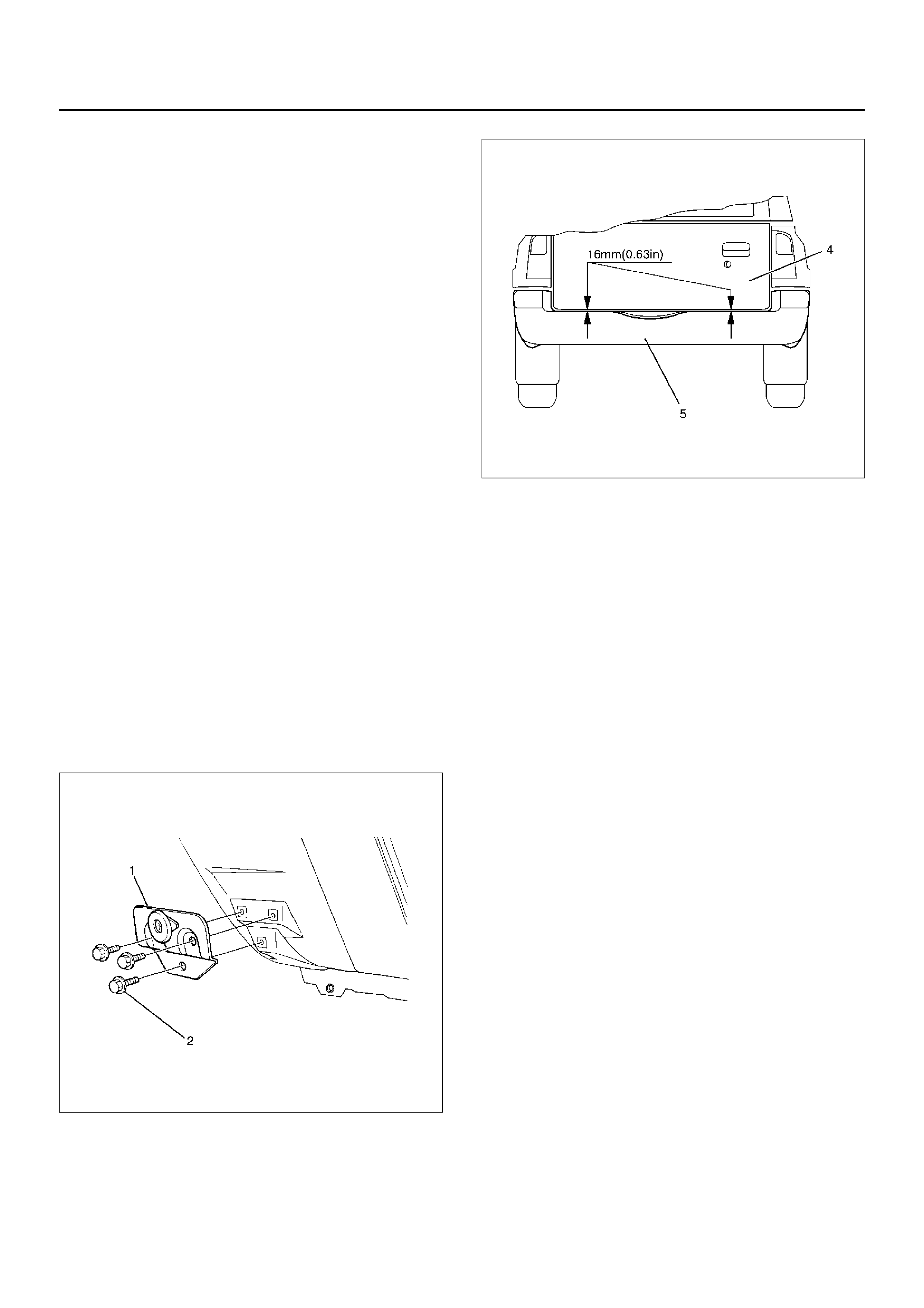
2. Rear bumper adjustment.
• When the bolts fixing rear bumper assembly are
tightened, adjustment should be made with shims
so that clearances shown in the figure below are
provided between the body (tailgate) (4) and the
rear bumper(5).
690RY00015
3. Tighten the spare tire fixing bolts to the specified
torque.
Torque : 118 N·m (12.0 kg·m/87 lb ft)
REAR BUMPER SLIDER
REMOVAL
1. Remove the Rear bumper.
• Refer to Rear bumper removal (in this section).
2. Remove the rear bumper slider(1).
• Remove the three bolts(2).
690RW016
INSTALLATION
To install, follow the removal steps in reverse order,
noting the foll owi ng poi nt:
1. Apply chassis grease to the slider and the slider
bracket moving surface.
GENERAL DESCRIPTION (SHEET METAL)
This section includes items of front end sheet metal that
are attached by bolts, screws or clips and related
accessory components.
Anticorrosion materials have been applied to the interior
surfaces of some metal panels to provide rust
resistance.
When servicing these panels, areas on which this
material has been disturbed, should be properly
recoated with service–type anticorrosion material.
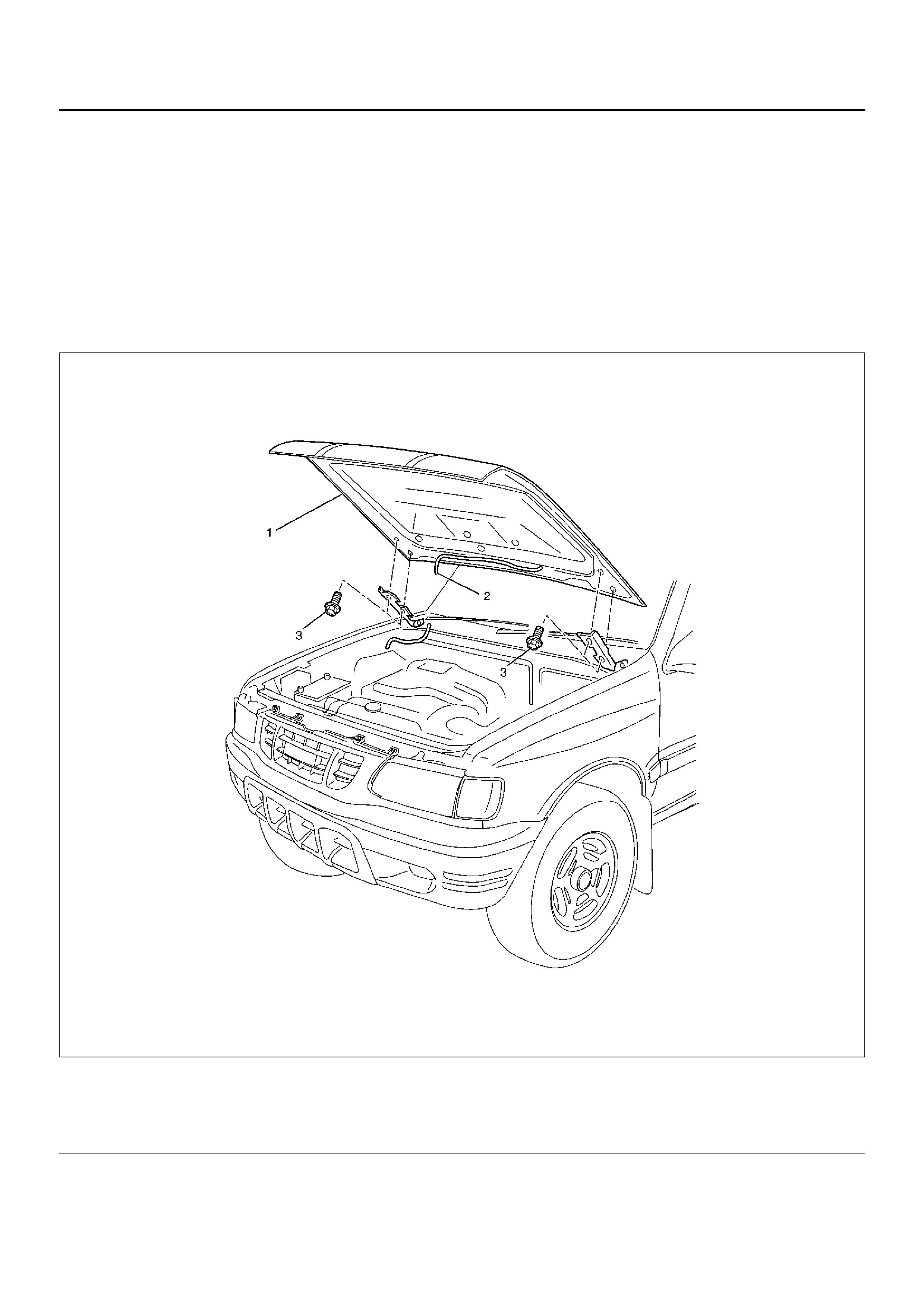
ENGINE HOOD
PARTS LOCATION
610RY00017
Legend
EndOFCallout
(1) Engine Hood Assembly
(2) Windowshield Washer Nozzle Tube (3) Hood Hinge Bolt
REMOVAL
1. Open the hood.
2. Support the hood.
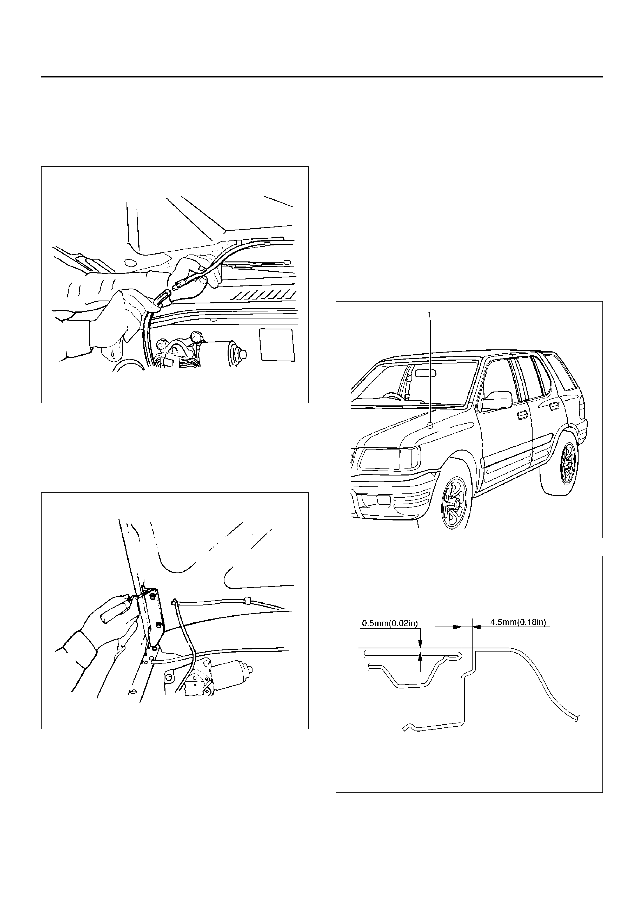
3. Remove the windshield washer nozzle tube.
880RS001
4. Remove the hood hinge bolts.
• Before removing the hinges from the engine
hood, scribe a mark showing location of the
hinges to facilitate installation in the original
position.
610RS006
5. Remove the engine hood.
INSTALLATION
To install, follow the removal steps in the reverse order,
noting the foll owi ng poi nts:
1. Tighten the engine hood hinge fixing bolts to the
specified torque.
Torque : 10 N·m (1.0 kg·m/87 lb in)
2. Check the engine hood and fender(1).
Clearance: 4.5 mm (0.18 in)
Height (step): 0.5 mm (0.02 in)
• Adjust clearance with the hinges on the engine
hood.
• Adjust height (step) with the hood buffers(2).
610RY00010
610RX001
610RY00008
ENGINE HOOD LOCK
PARTS LOCATION
610RY00024
Legend
EndOFCallout
REMOVAL
1. Remove the hood lock control lever.
2. Remove the inner liner.
3. Remove the radiator grille.
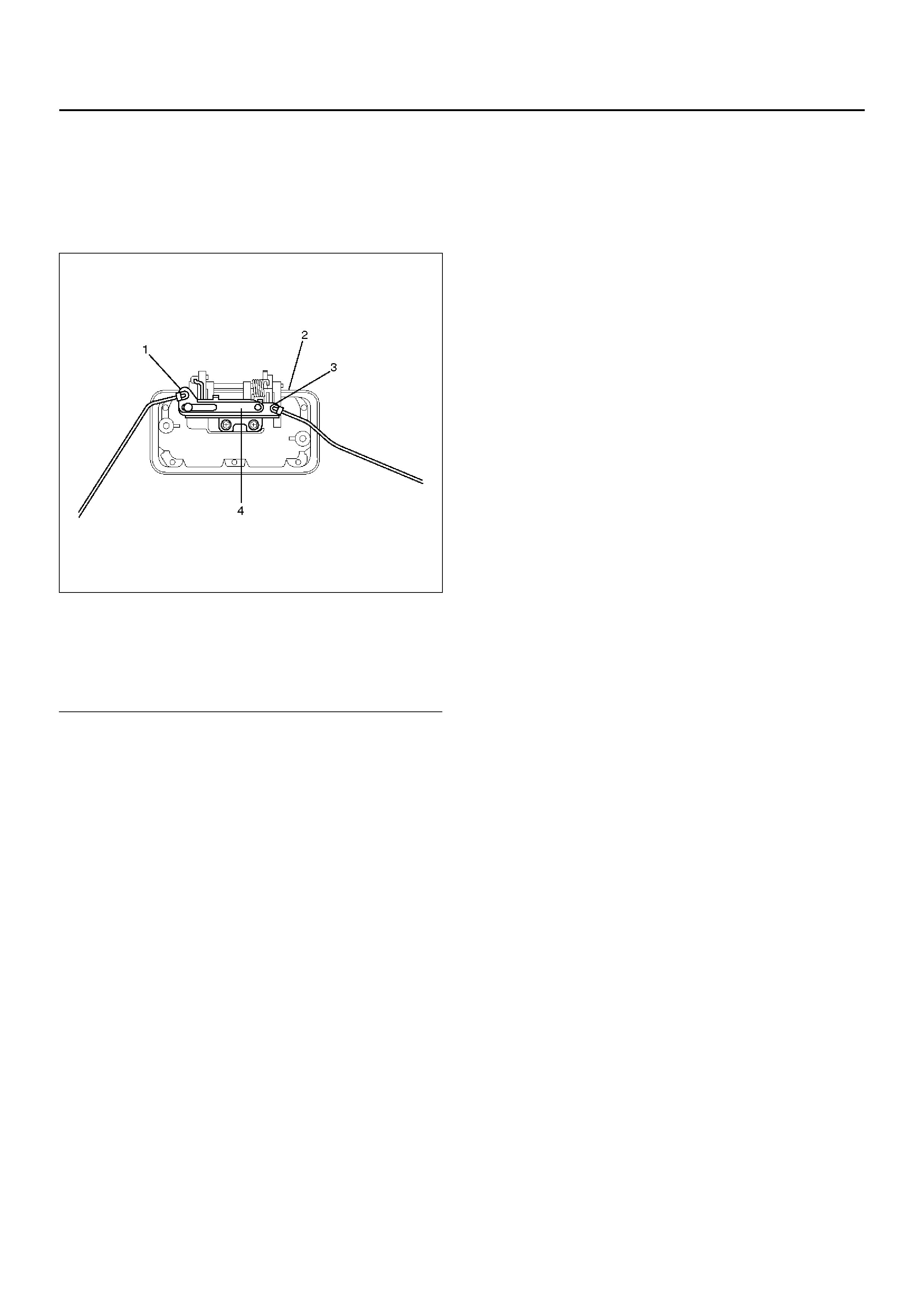
• Refer to Radiator Grille in this section.
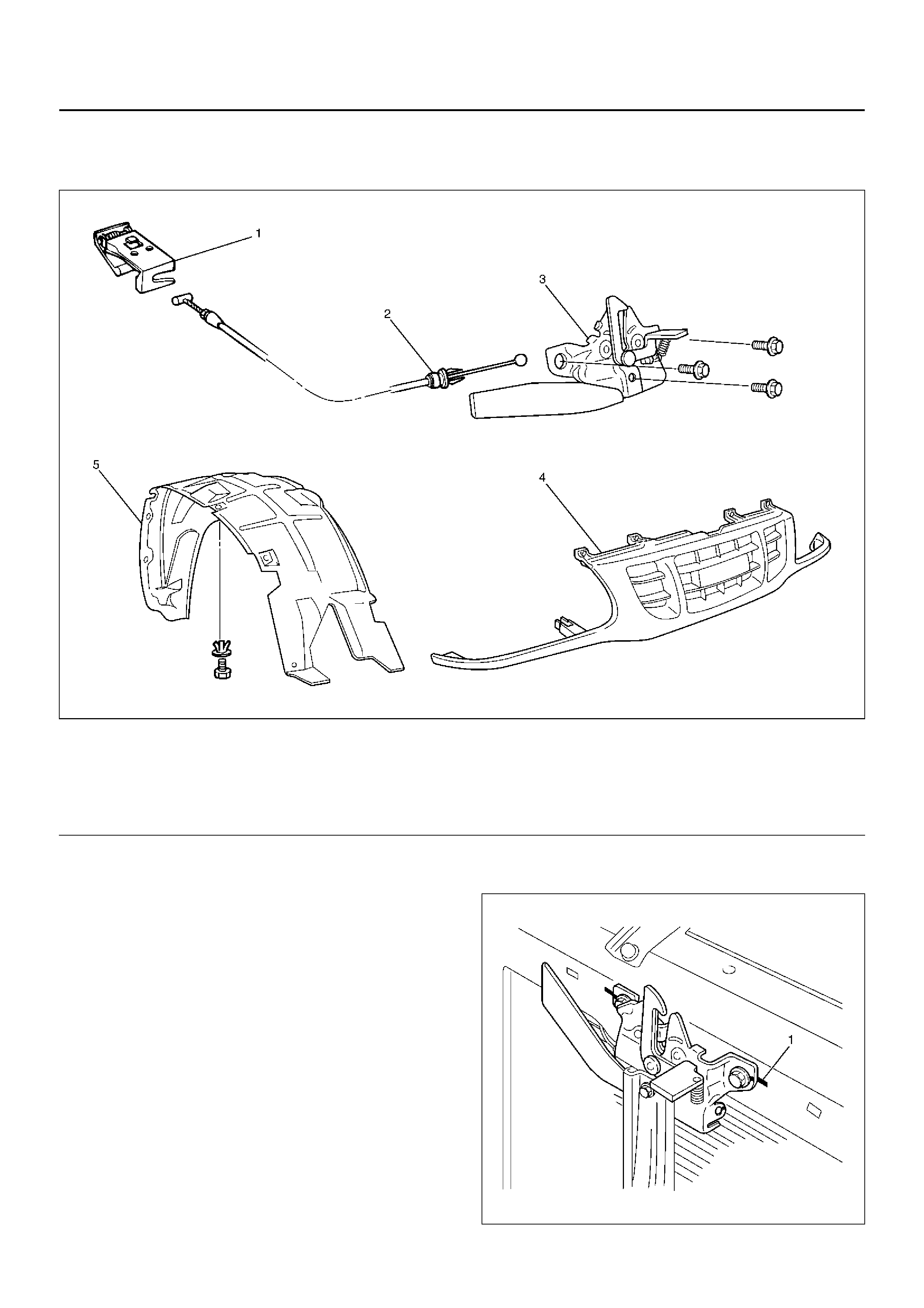
4. Remove the engine hood lock assembly.
• Apply se ttin g ma rks(1) to t he hood lock asse mbly
and the body prior to removal.
610RY00020
(1) Hood Lock Control Lever
(2) Control Cable
(3) Engine Hood Lock Assembly
(4) Radiator Grille
(5) Inner Liner
5. Remove the control cable.
• Remove the cable fixing clips from the engine
hood lock.
INSTALLATION
To install, follow the removal steps in the reverse order
noting the following points.
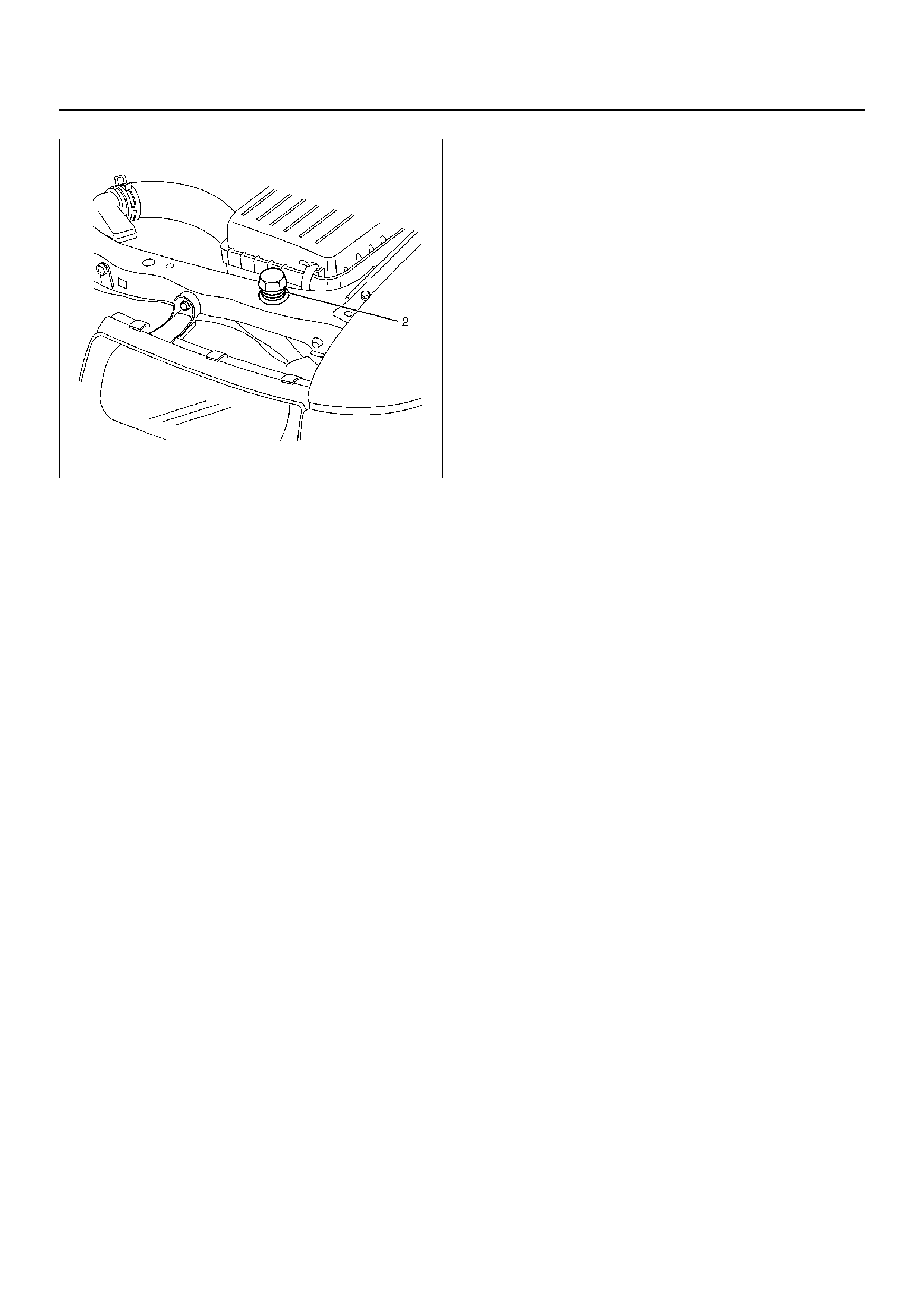
1. Set the position of installing the engine hood lock
assembly (4).
• Install the buffers (3) to the body.
• Adjust the buffers as the position of the engine
hood (1) is 2mm to the fender panel (2).
2. Fix the engine hood lock assembly.
• Tighten the hood lock assembly fixing bolts under
condition 1 to the specified torque.
Torque : 10 N·m (1.0 kg·m/87 lb in)
610RY00021
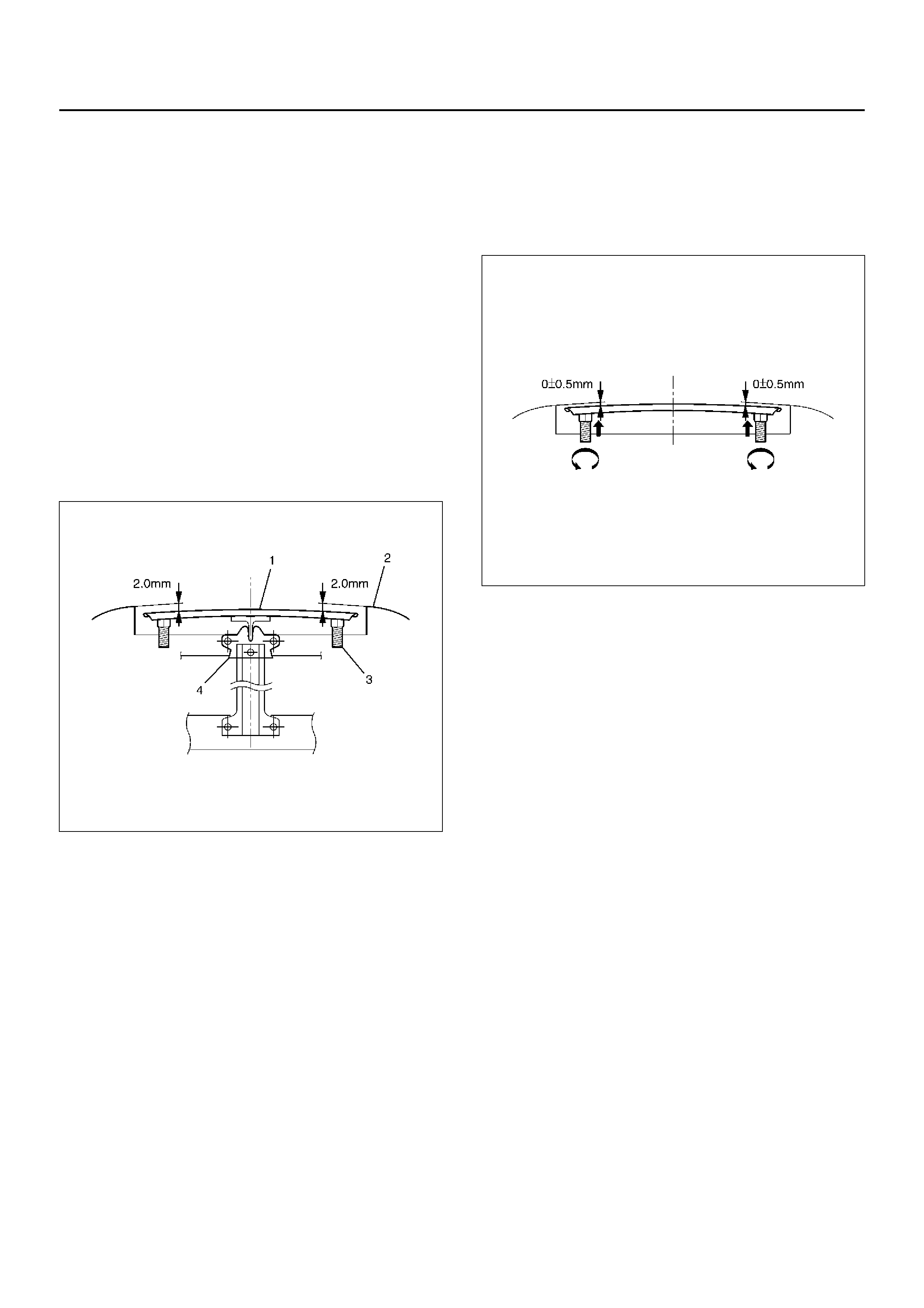
3. Adjust the appearance quality. (Engine hood and
fender panel)
• By buffers, adjust the difference of the height of
engine hood is 0±0.5mm to the fender. (Turn the
buffers approx. one revolution and move the
position of buffers upward.)
610RY00022
4. Reroute the control cable to its original position, and
check and see if the lock assembly and control lever
work normaly.
RADIATOR GRILLE
PARTS LOCATION
603RY00010
Legend
EndOFCallout
REMOVAL
1. Open the hood.
2. Support the hood.
3. Remo ve radiator grill e.
• Raise the clips on the radiator grille and remove
screw.
603RY00011
(1) Radiator Grille Rubber
(2) Screw (3) Radiator Grille Assem bly
(4) Clip

4. Pull out the radiator grille rubber from fender panel
front lower side.
INSTALLATION
To install, follow the removal steps in the reverse order,
noting the following point.
1. Install the radiator grille clips remaining on the body
side in the radiator grille, and then install the radiator
grille on the body.
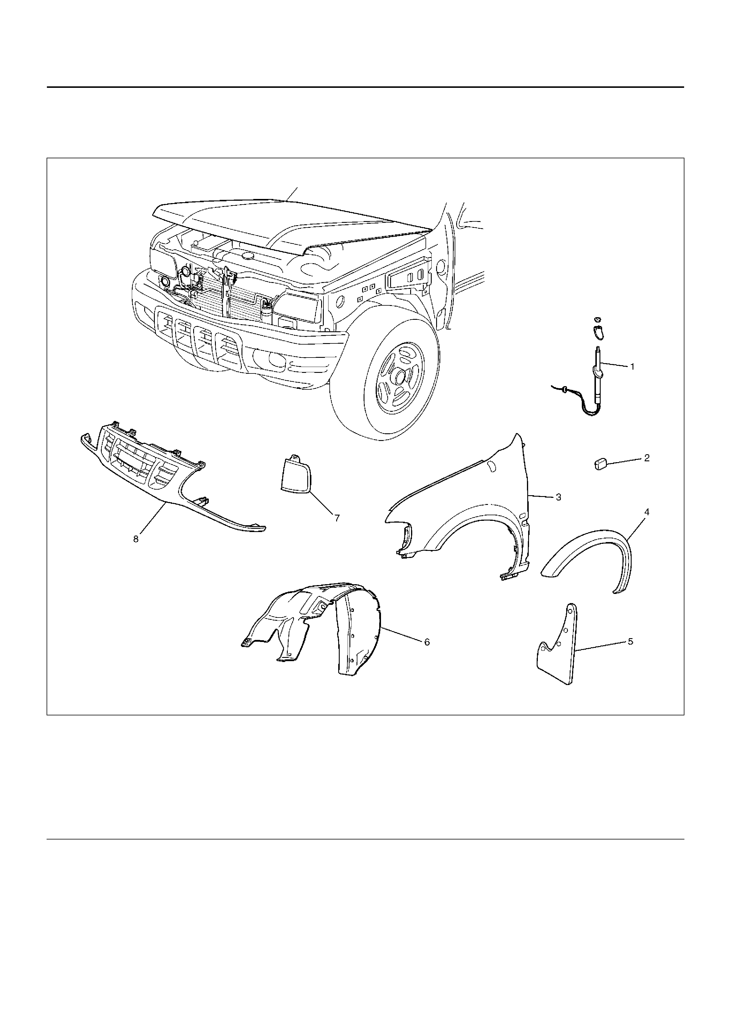
FRONT FENDER PANEL
PARTS LOCATION
605RY00004
Legend
EndOFCallout
REMOVAL
1. Disconnect the battery ground cable.
2. Remove the radiator grille assembly.
• Refer to Radiator Grille in this section.
(1) Ante nna Assembly
(2) Side Turn Signal Light
(3) Front Fender Panel
(4) Front Wheel Arch Moulding (If so equipped)
(5) Front Mud Flap
(6) Inner Liner
(7) Fr ont Turn Sign al Lig ht Ass em bl y
(8) Radiator Grille
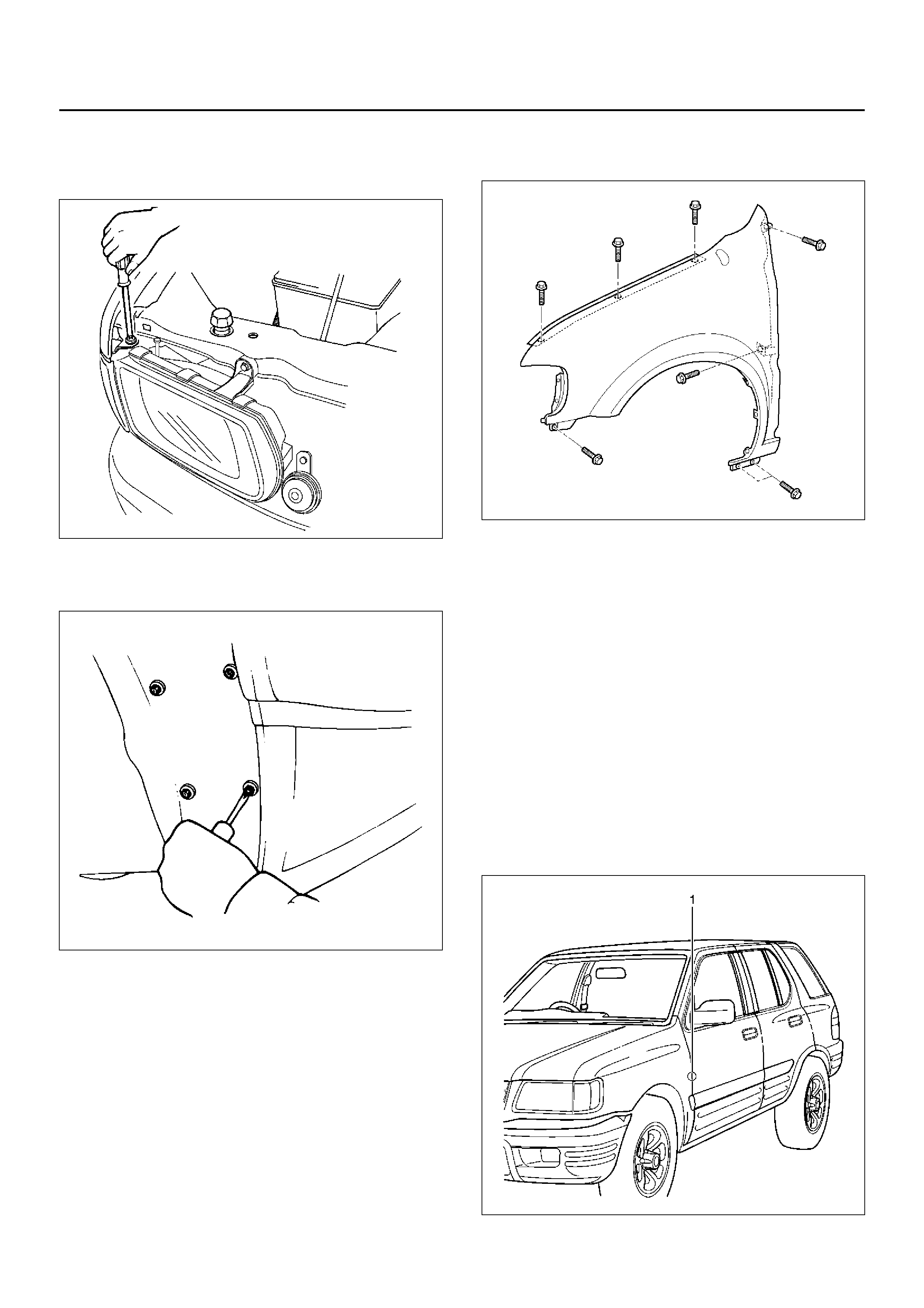
3. Remove the front turn signal light assembly.
• Remove the fixing screws and disconnect the
connector.
801RY00005
4. Remove the front mud flap.
5. Remove the inner liner.
647RY00003
6. Remove the antenna assembly.
• Refer to Rod Type Antenna in Entertainment
section.
7. Remove the side turn signal light.
• Refer to Side Turn Signal Light Bulb in Lighting
System section.
8. Remove the front fender panel.
• Remove the eight fixing bolts.
614RX006
9. Remove the front wheel arch moulding (If so
equipped).
• Refer to Wheel Arch Moulding in Exterior/Interior
Trim section.
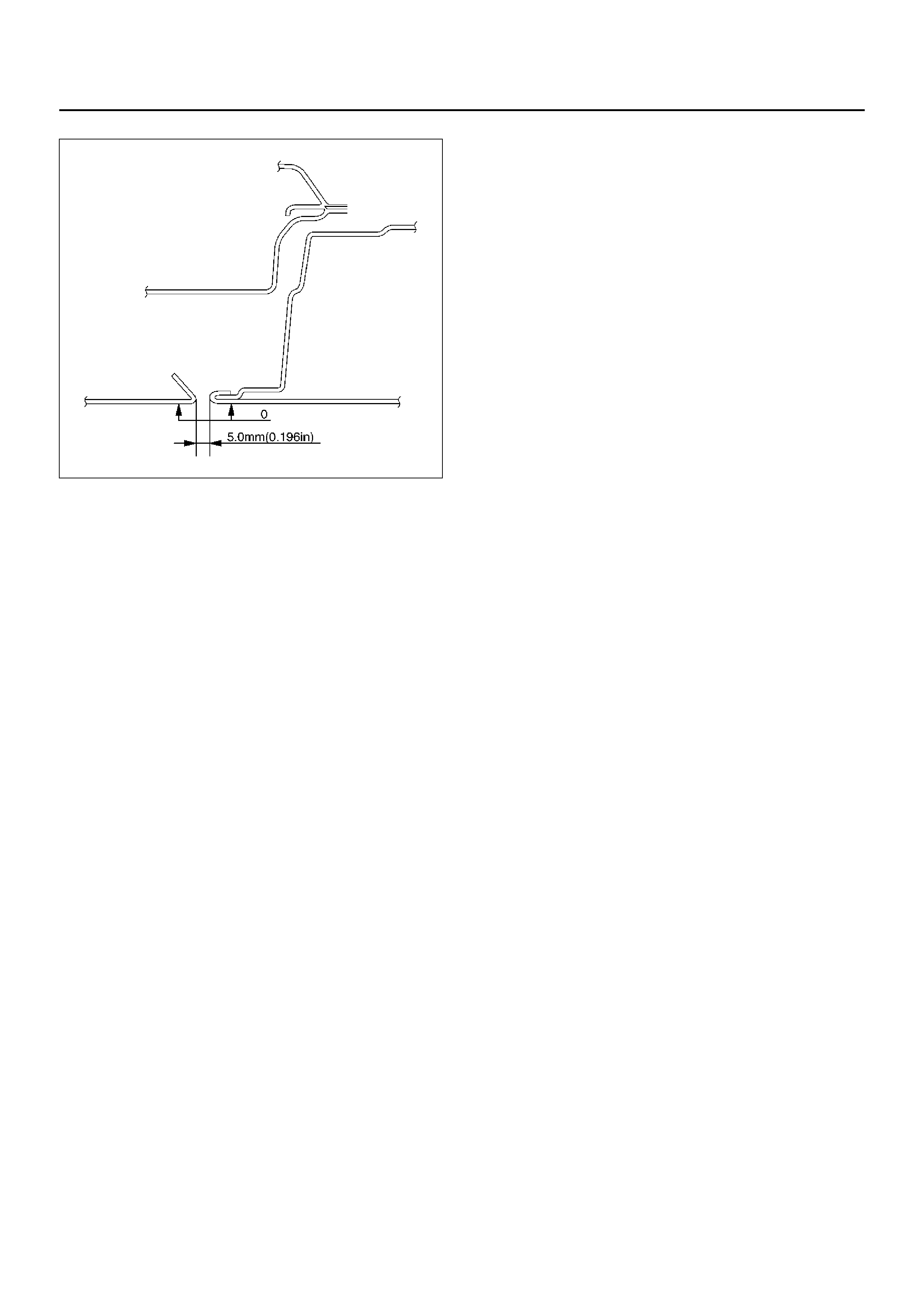
INSTALLATION
To install, follow the removal steps in the reverse order,
noting the foll owi ng poi nts:
1. Tighten the front fender panel fixing bolts to the
specified torque.
Torque : 7 N·m (0.7 kg·m/61 lb in)
2. Check the fender and front door(1).
Clearance: 5.0 mm (0.196 in)
Height (step): Flush
610RY00015
610RW001
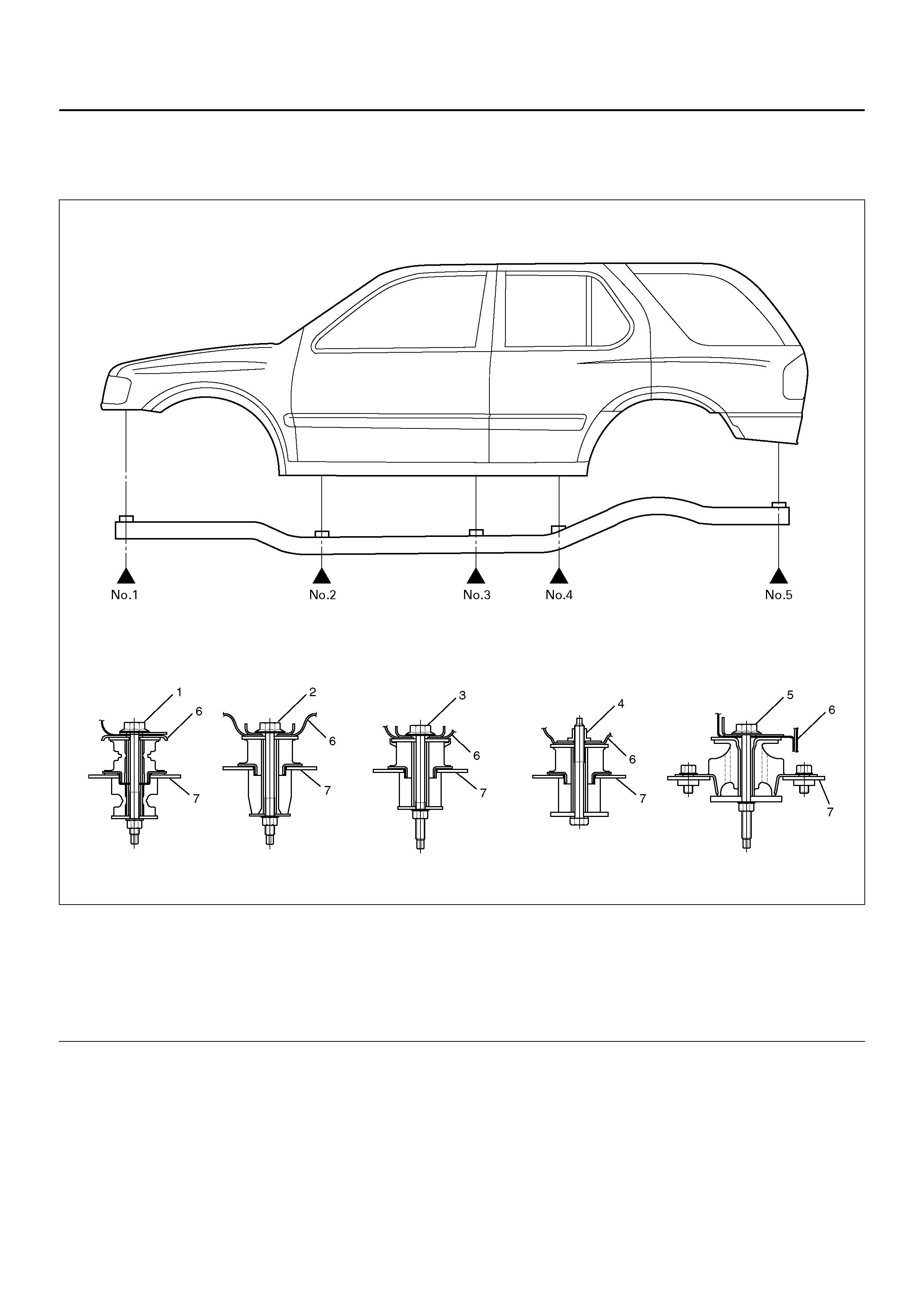
BODY MOUNTING
PARTS LOCATION
501R100003
Legend
EndOFCallout
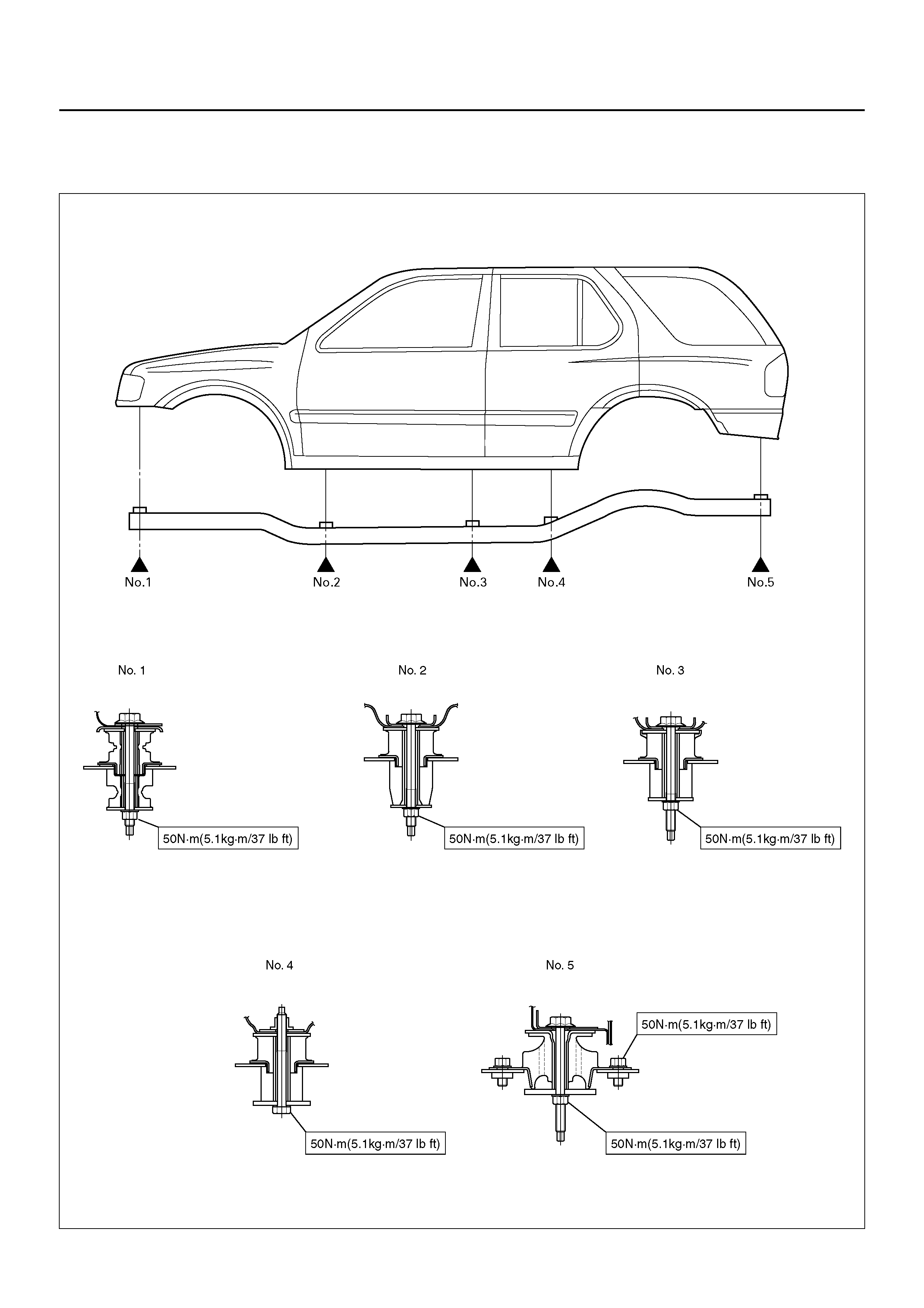
TIGHTENING TORQUE
1. Tighten the body mounting bolts to specified torque.
Torque : 50 N·m (5.1 kg·m/41 lb ft)
(1) No.1 Body Mounting
(2) No.2 Body Mounting
(3) No.3 Body Mounting
(4) No.4 Body Mounting
(5) No.5 Body Mounting
(6) Body Side Mounting Bracket
(7) Frame Side Mounting Bracket

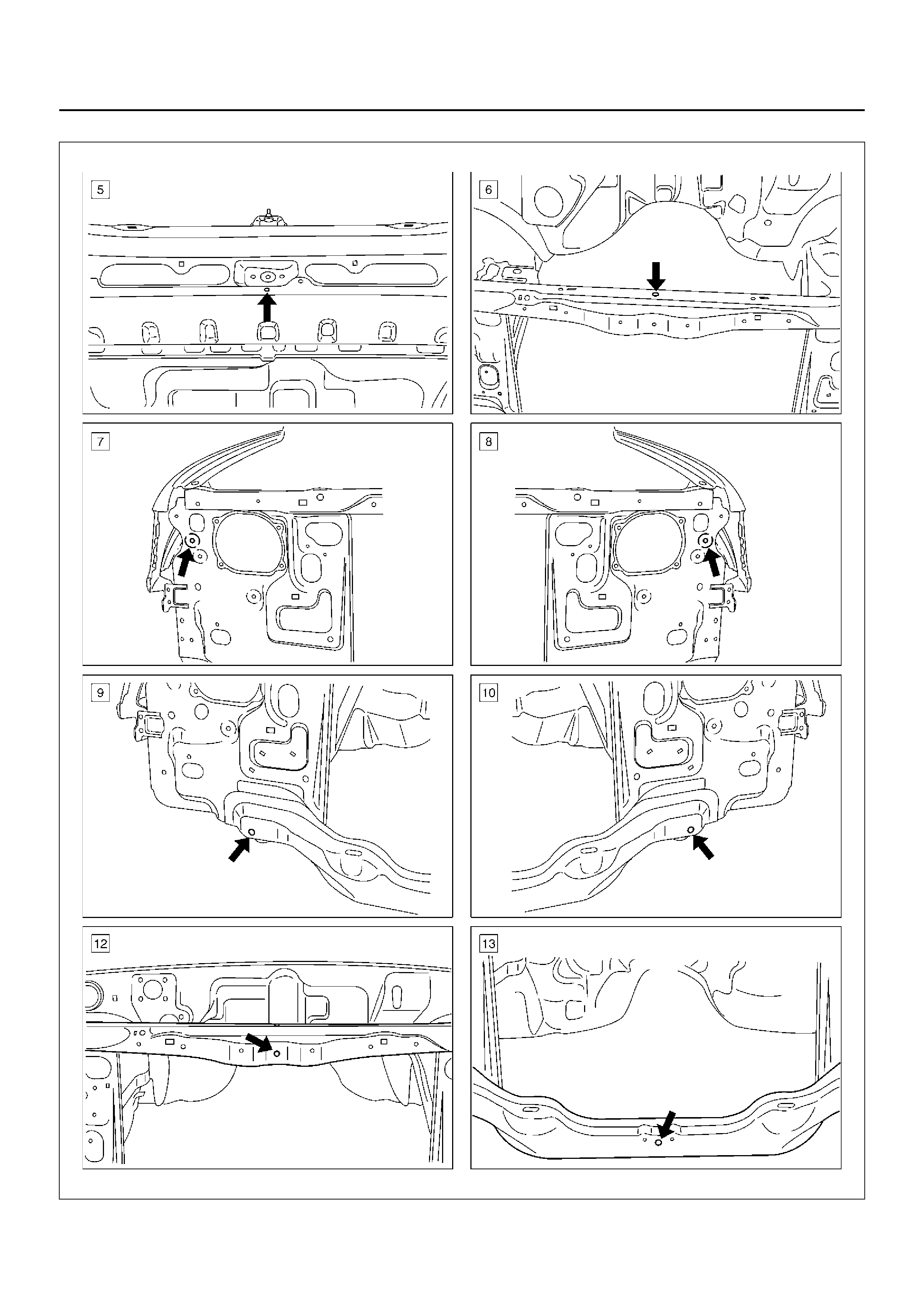
BODY DIMENSION
FRONT SECTION
A10RW034
A10RW035

A10RW036
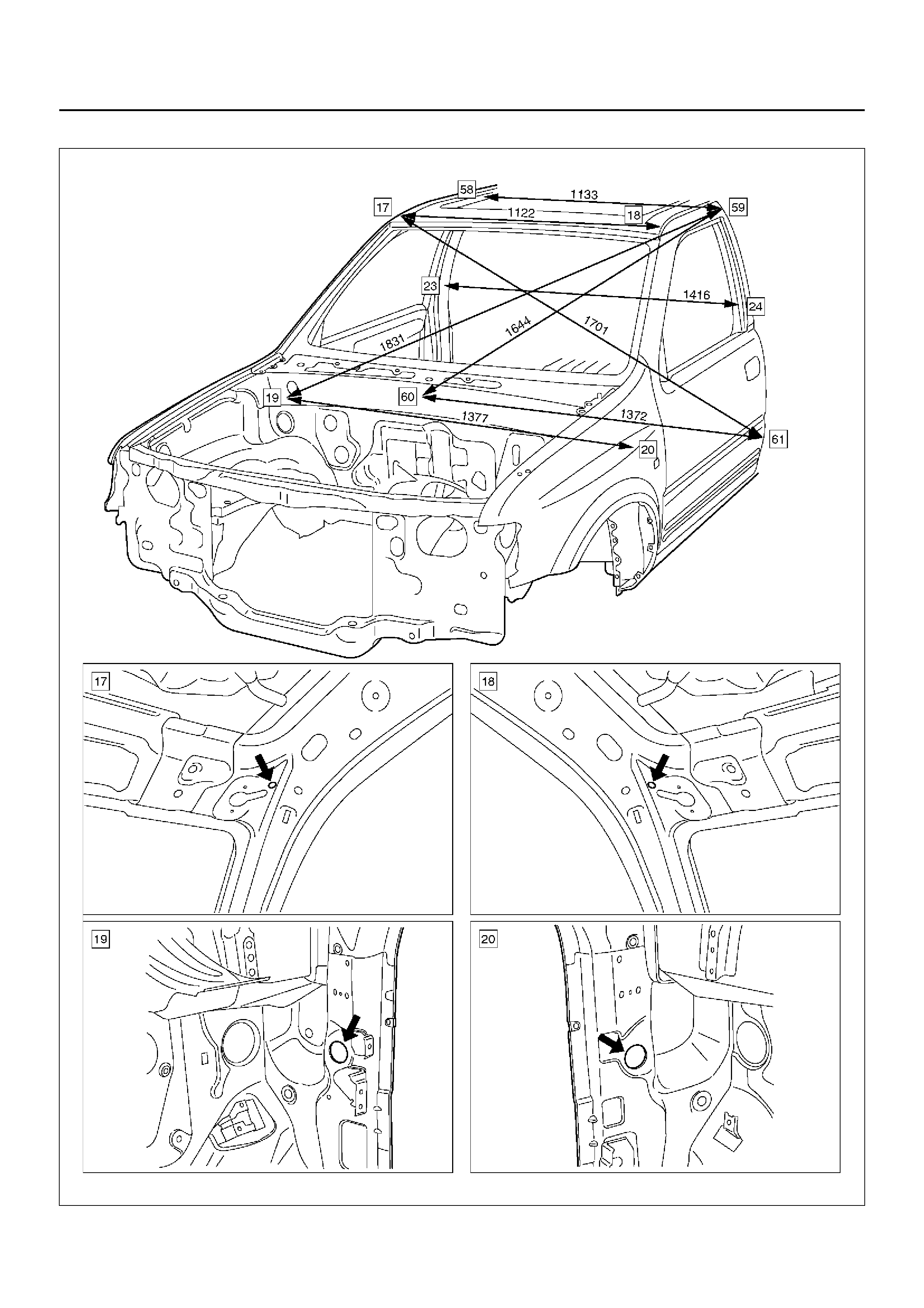
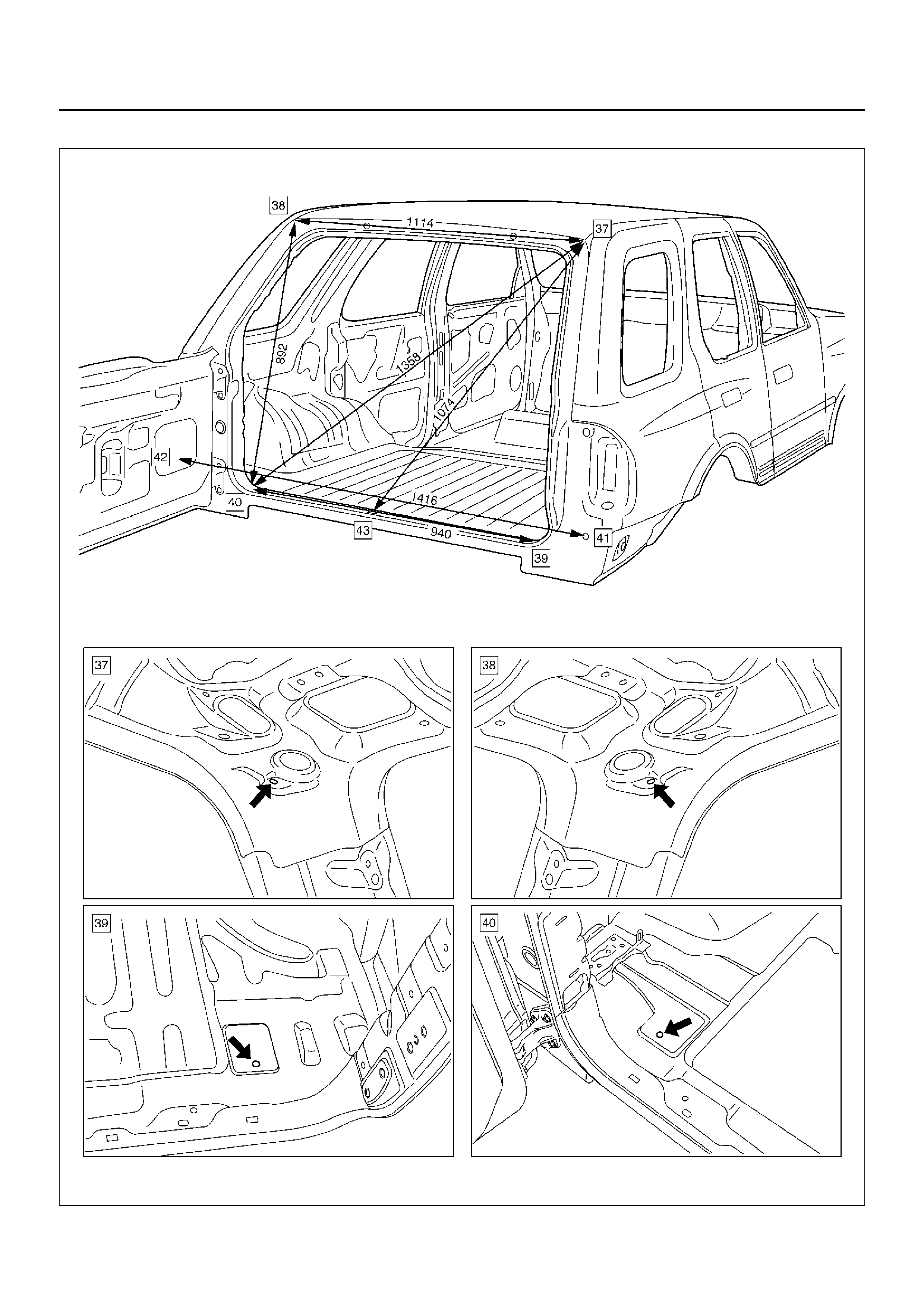
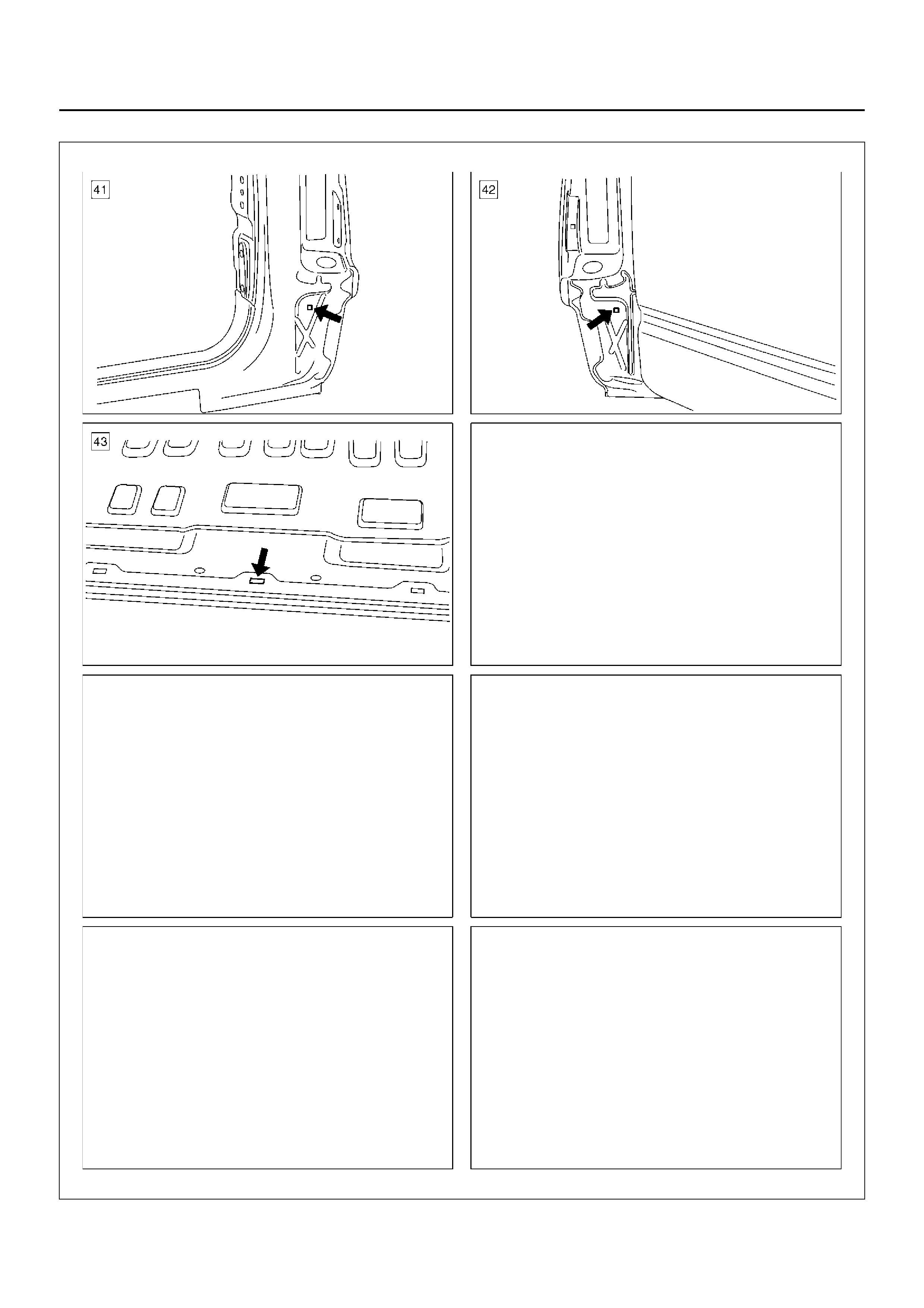
ROOM SECTION (FRONT SIDE)
A10R100001
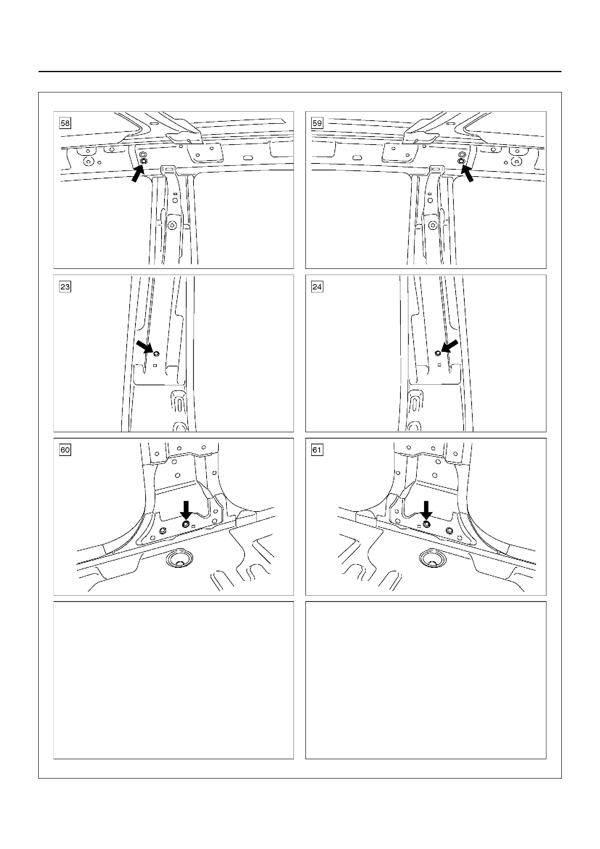
A10R100002
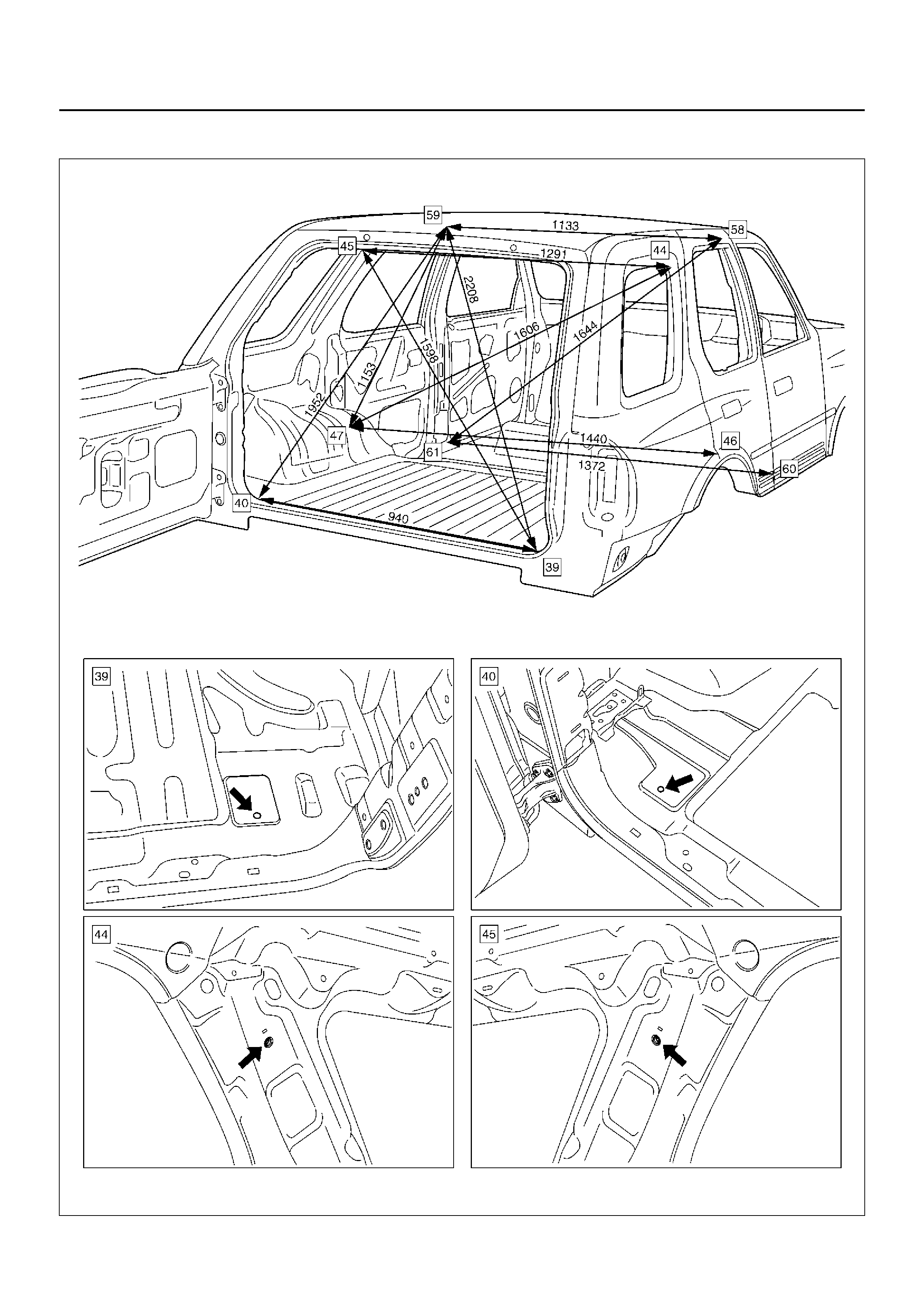
ROOM SECTION (REAR SIDE)
A
1
0
R
W
0
3
9
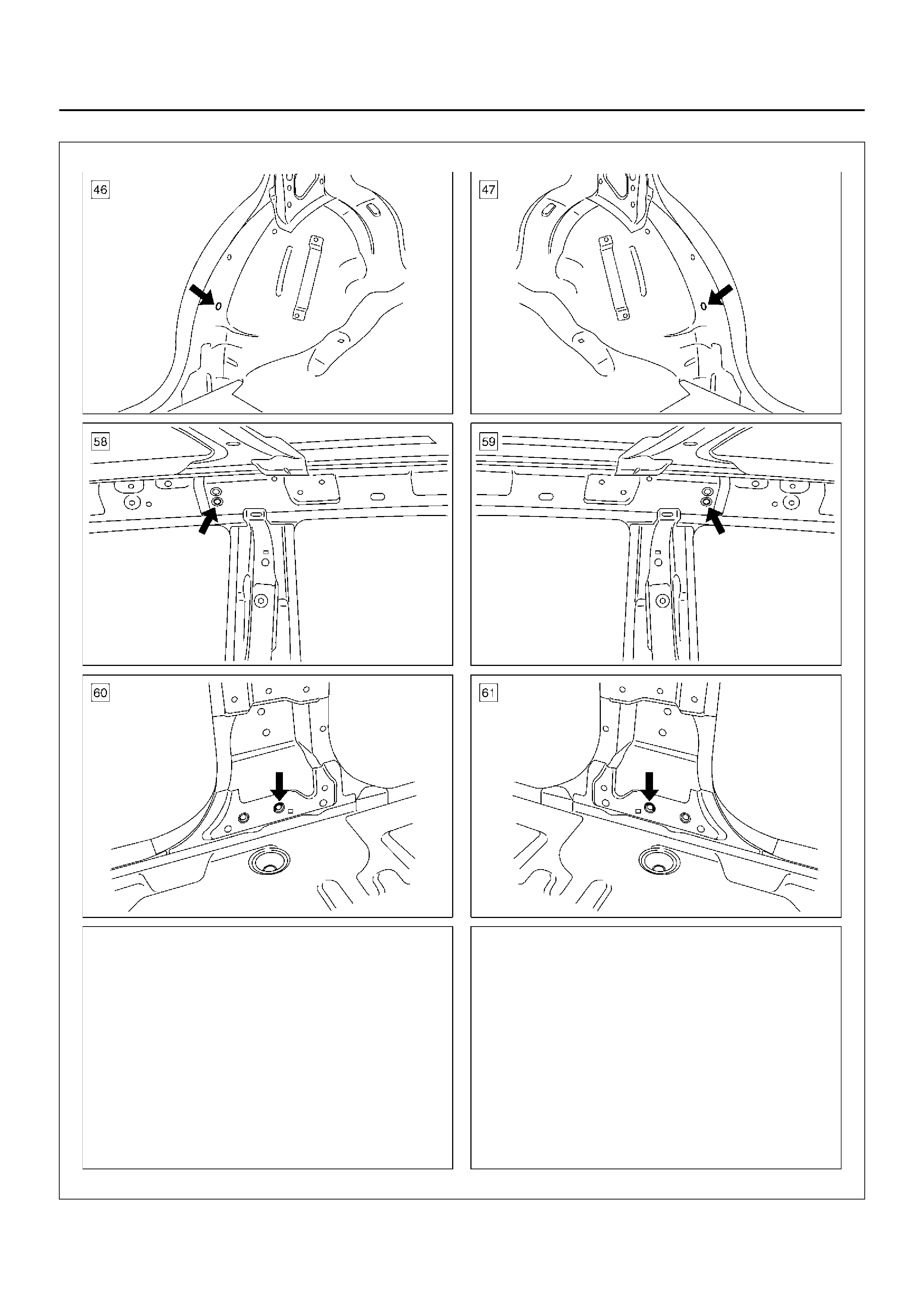
A10RW040
REAR SECTION
A10RW043
A10RW044
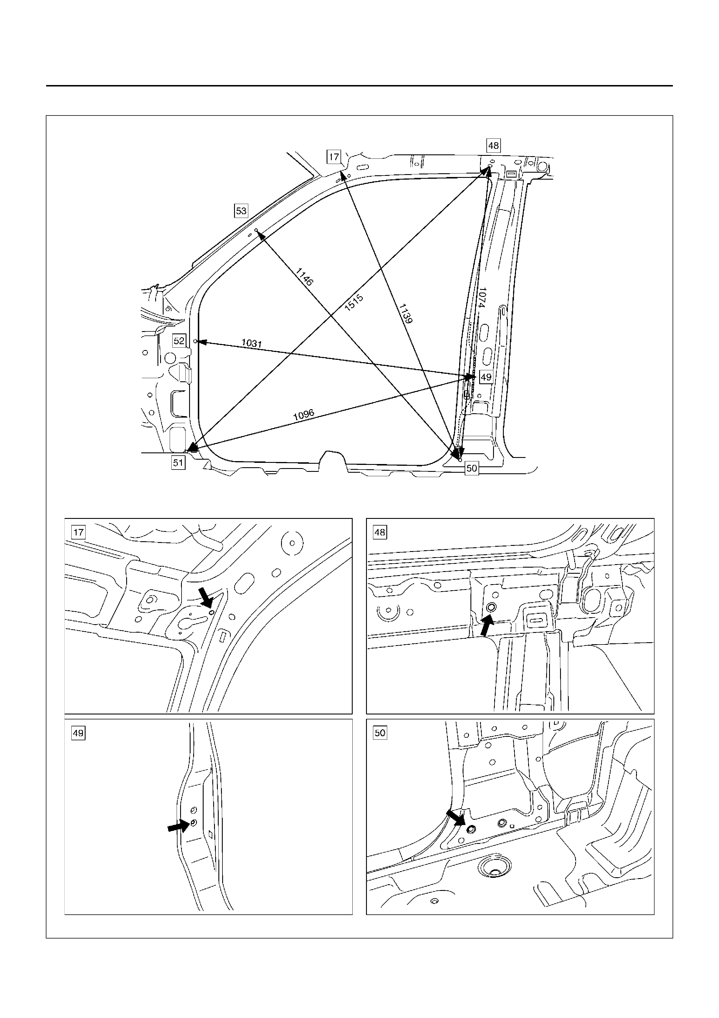
SIDE BODY SECTION (FRONT SIDE)
A10RW045
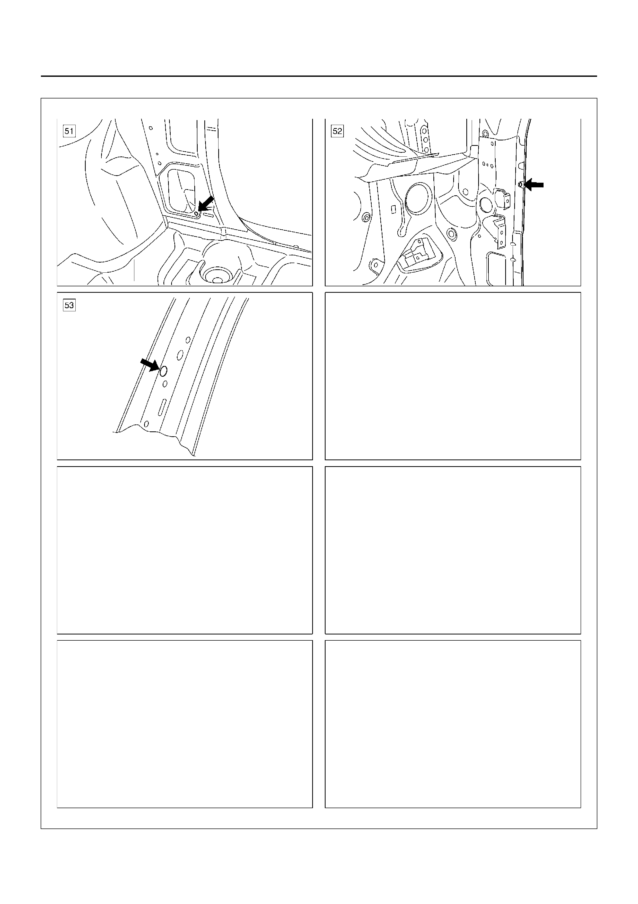
A10RW046
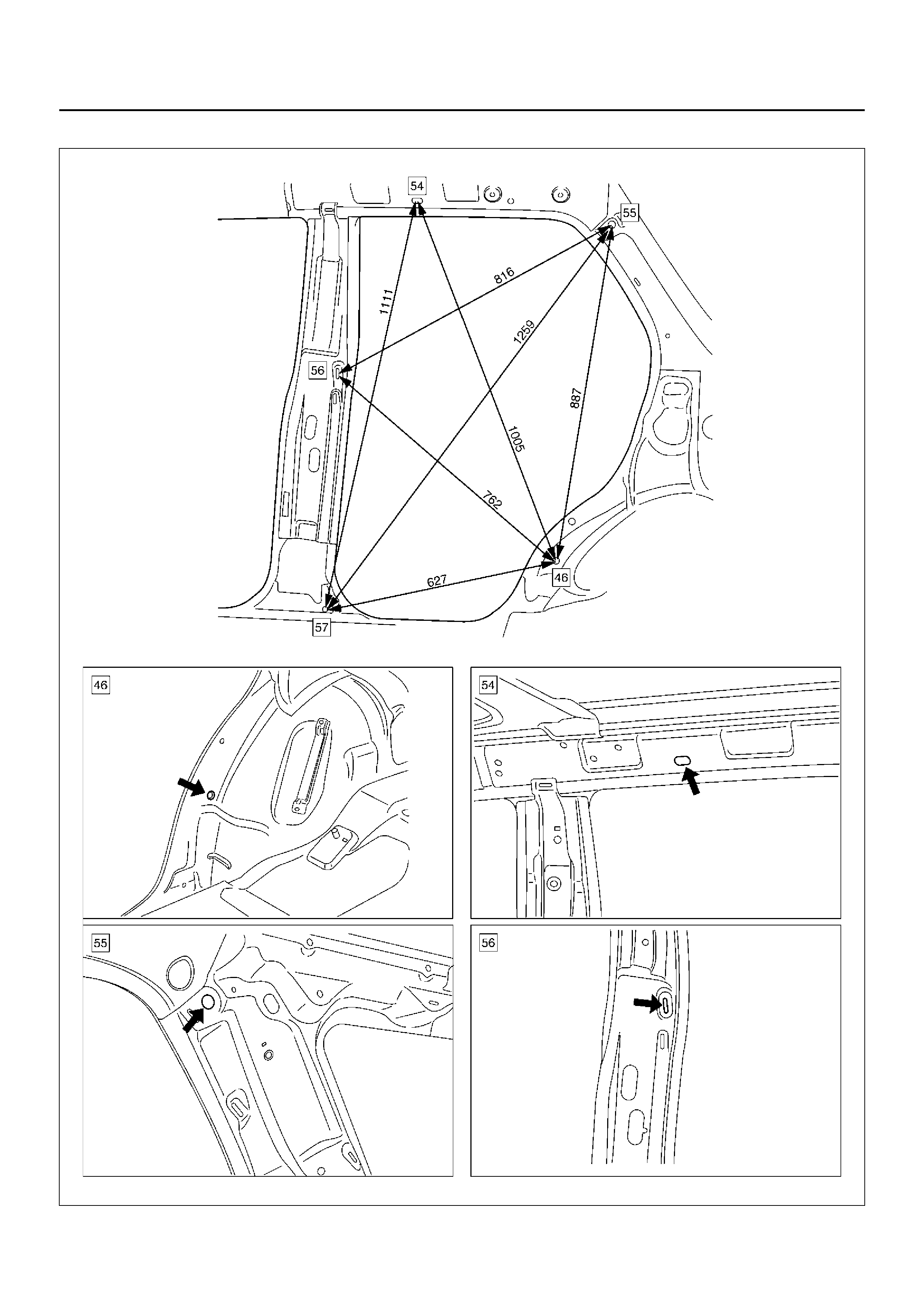
SIDE BODY SECTION (REAR SIDE)
A10RW047
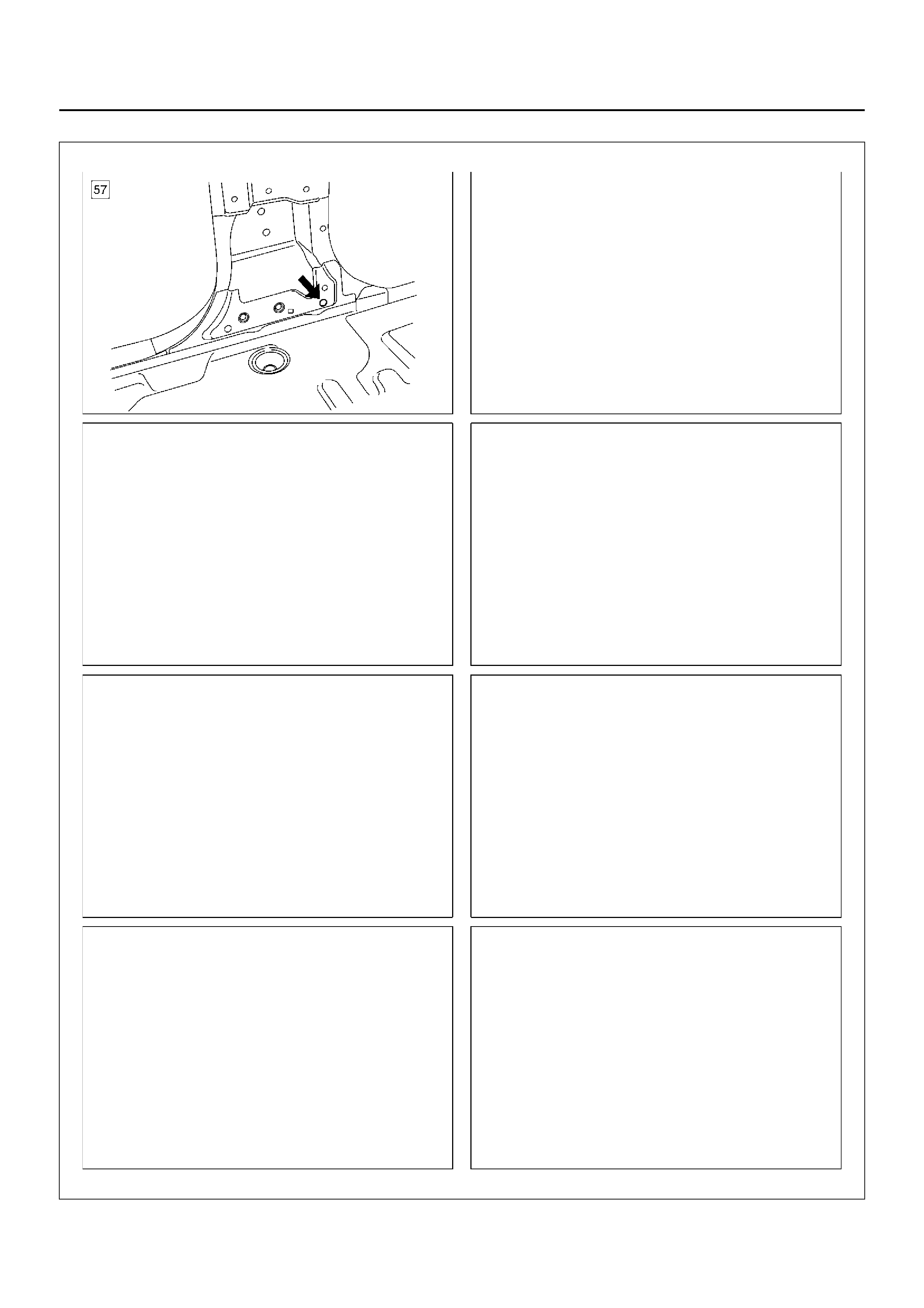
A10RW048
GENERAL DESCRIPTION (BODY)
This publication contains essential removal, installation,
adjustment and maintenance procedures.
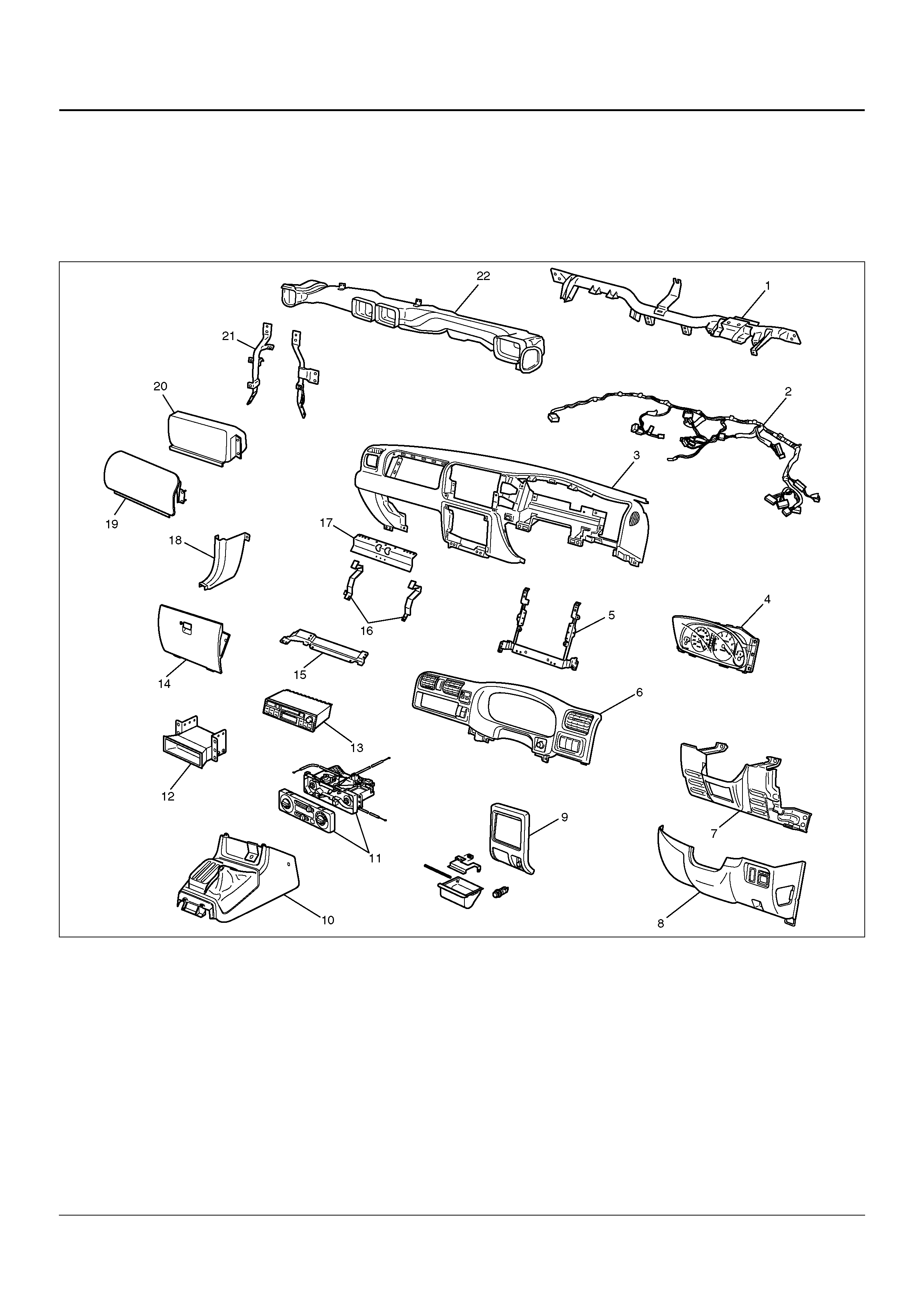
INSTRUMENT PANEL ASSEMBLY
PARTS LOCATION
740R100009
Legend
EndOFCallout
(1) Cross Beam
(2) Instrument Harness Assembly
(3) Instrument Panel Assembly
(4) Meter Assembly
(5) Instrument Panel Center Reinforcement
(6) Instrument Facia
(7) Driver knee Bolster Assembly
(8) Instrument Panel Driver Lower Cove r Assembly
(9) Lower Cluster Assembly
(10) Front Console Assembly
(11) Control Lever Assembly
(12) Audio Sub Box
(13) Radio Assembly
(14) Glove Box
(15) Passenger Lower Bracket
(16) Glove Box Side Reinforcement
(17) Instrum ent Uppe r Rei nforc eme nt
(18) Dash Side Trim Panel
(19) Passenger Air Bag Cover
(20) Passenger Air Bag
(21) Instr um ent Pa nel Stay
(22) Vent Du ct Assembly
REMOVAL
CAUTION: For precautions on installation or
removal of SRS – air bag system, refer to
Supplemental Restraint System (SRS) – AIR BAG in
Restraint section.
1. Disconnect the battery ground cable.
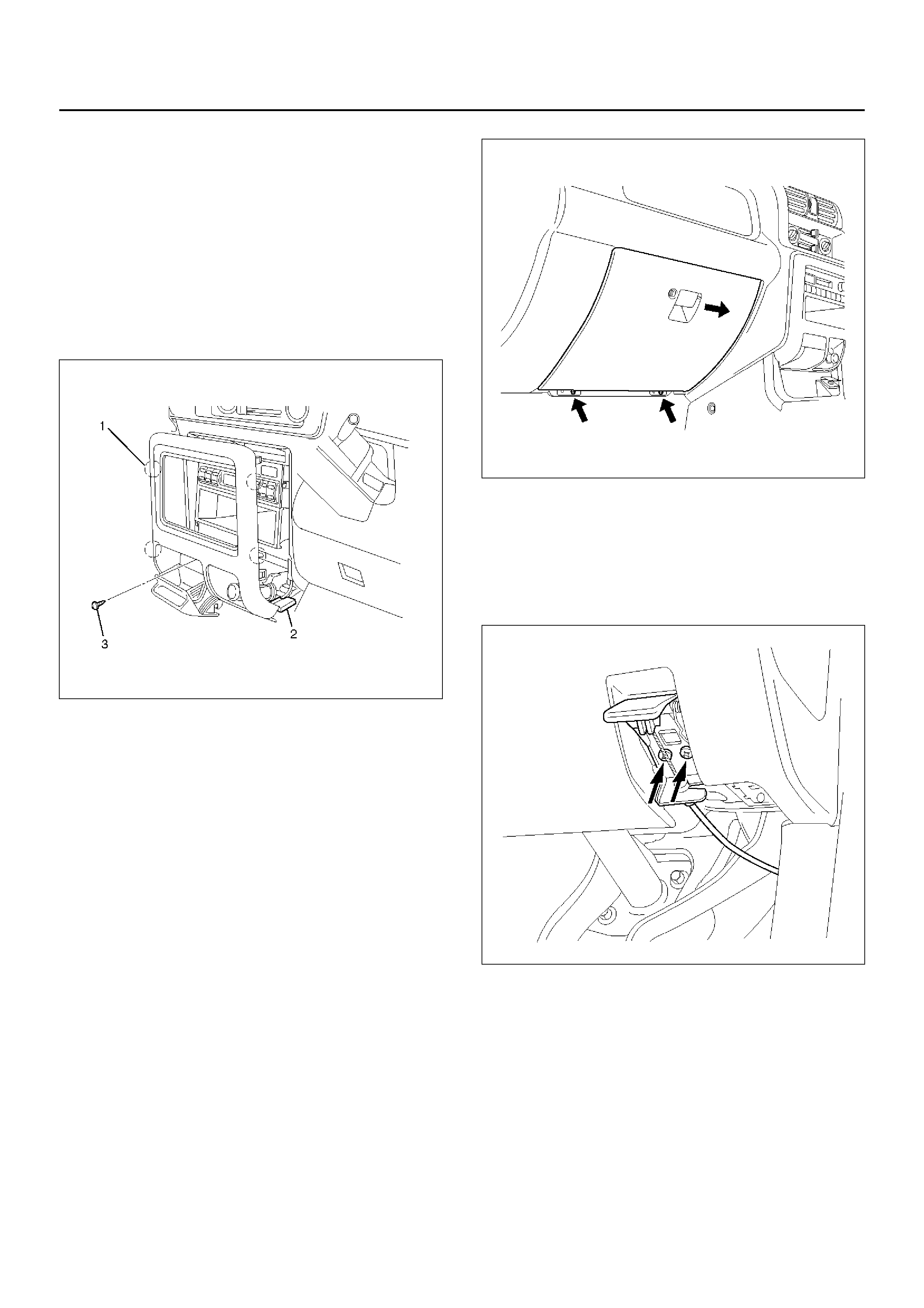
2. Remove the lower cluster assembly.
• Remove screw (3) and pull out the cluster at the
clip positions (1).
• Disconnect the cigarette lighter connectors (2).
470RW006
3. Remove the radio assembly and audio sub box.
• Refer to Radio in Entertainment section.
4. Remove the front and rear consoles.
• Refer to Consoles in Exterior/Interior Trim
section.
5. Remove the dash side trim panels.
• Remove the sill plates, then remove the trim
panels.
6. Remove the glove box.
• Remove the two fixing screws.
470RW007
7. Remove the instrument panel driver lower cover
assembly.
• Remove the engine hood opener two fixing
screws and another one fixing screw.
After four clips are pried, disconnect switch
connector and duct.
610RW023
8. Remove the Instrument Facia.
• Remove the five fixing screws, two clips and
switch connectors.
9. Remove the meter assembly.
• Remove the four fixing screws and disconnect
the connectors.
10. Remove the driver knee bolster assembly.
• Remove the six fixing bolts and screw.
11. Remove the control lever assembly.
• Refer to Control Lever Assembly and/or Control
Cable in Heating, Ventilation and Air Conditioning
(HVAC) section.
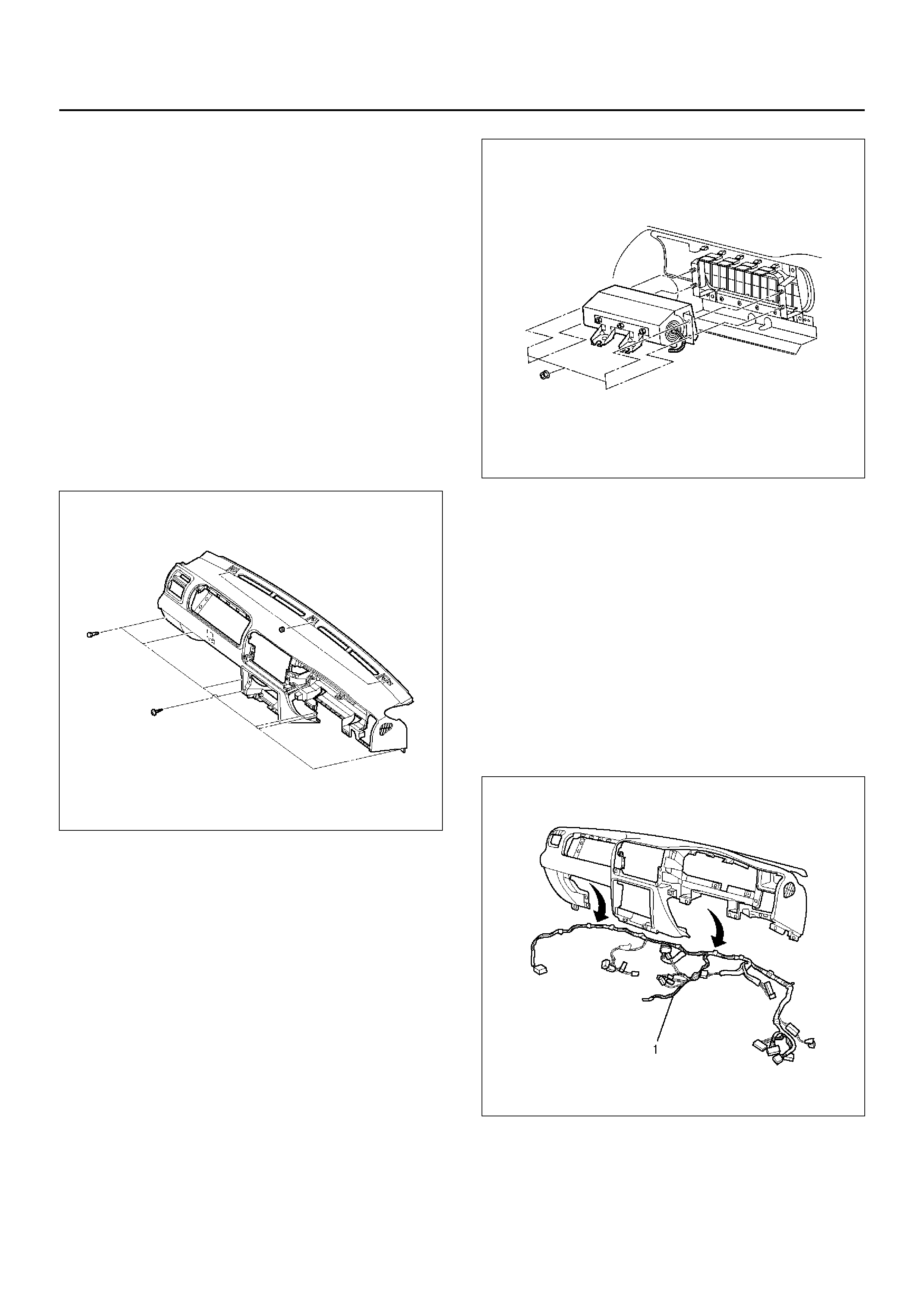
12. Remove the Instrument panel assembly.
CAUTION: For precautions on installation or
removal of SRS – air bag system, refer to
Supplemental Restraint System (SRS) – AIR BAG in
Restraint section.
• Disconnect the instrument harness connectors
(six connectors on the driver's side, three
connectors on the passenger side and two
connectors on the center side).
• Disconnect radio antenna cable plug and the
ground cable fixing bolts from dash side panel.
• Remove the two fixing bolts of passenger air bag
assembly and disconnect the connector.
• Remove the two fixing screws from fuse box.
• After pry the three hole cover from the surface of
instrument panel, remove the three nuts.
• Remove the six bolts and one screw.
740RX070
13. Remove the passenger air bag.
• Remove the four fixing nuts.
CAUTION: For precautions on installation or
removal of SRS – air bag system, refer to
Supplemental Restraint System in Restraint
section.
827RY00004
14. Remove the vent duct assembly.
• Remove the five fixing screws.
15. Remove the passenger lower bracket.
• Remove the three screw s.
16. Remove the glove box side reinforcement.
17. Remove the instrument upper reinforcement.
• Remove the nine screws.
18. Remove the instrument panel center reinforcement.
• Remove the six screws.
19. Remove the instrument panel harness assembly
(1).
• Remove the clips.
740RX069
20. Remove the instrument panel stays.
• Remove the two fixing nuts and two fixing bolts
for each bracket.
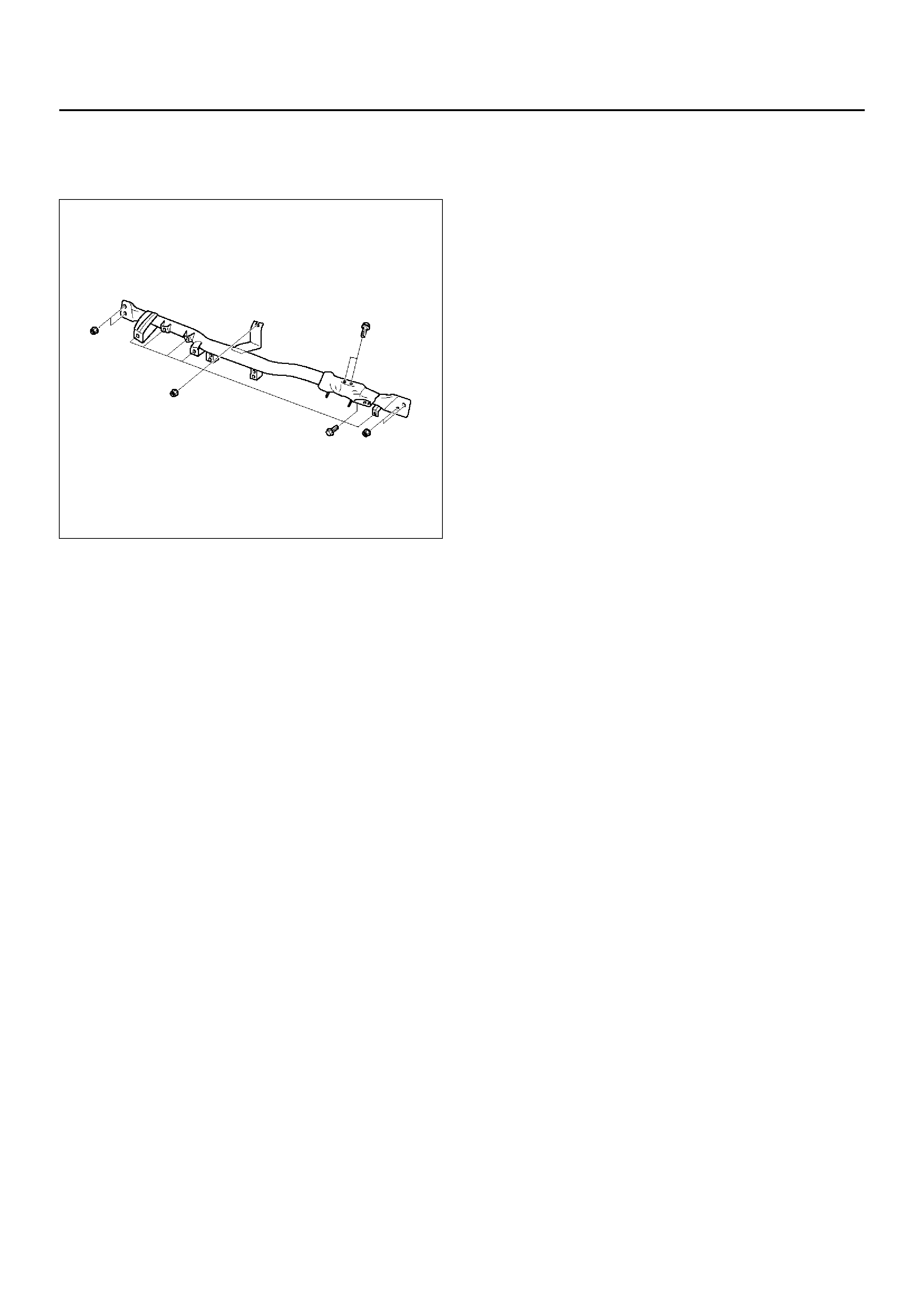
21. Remove the cross beam.
• Remove the five fixing nuts, two fixing bolts
(upper) and six fixing bolts (lower).
840RW025
INSTALLATION
To install, follow the removal steps in the reverse order,
noting the following point.
1. Adjust the control cable.
• Refer to Control Lever Assembly in Heating,
Ventilation and Air Conditioning (HVAC) section.
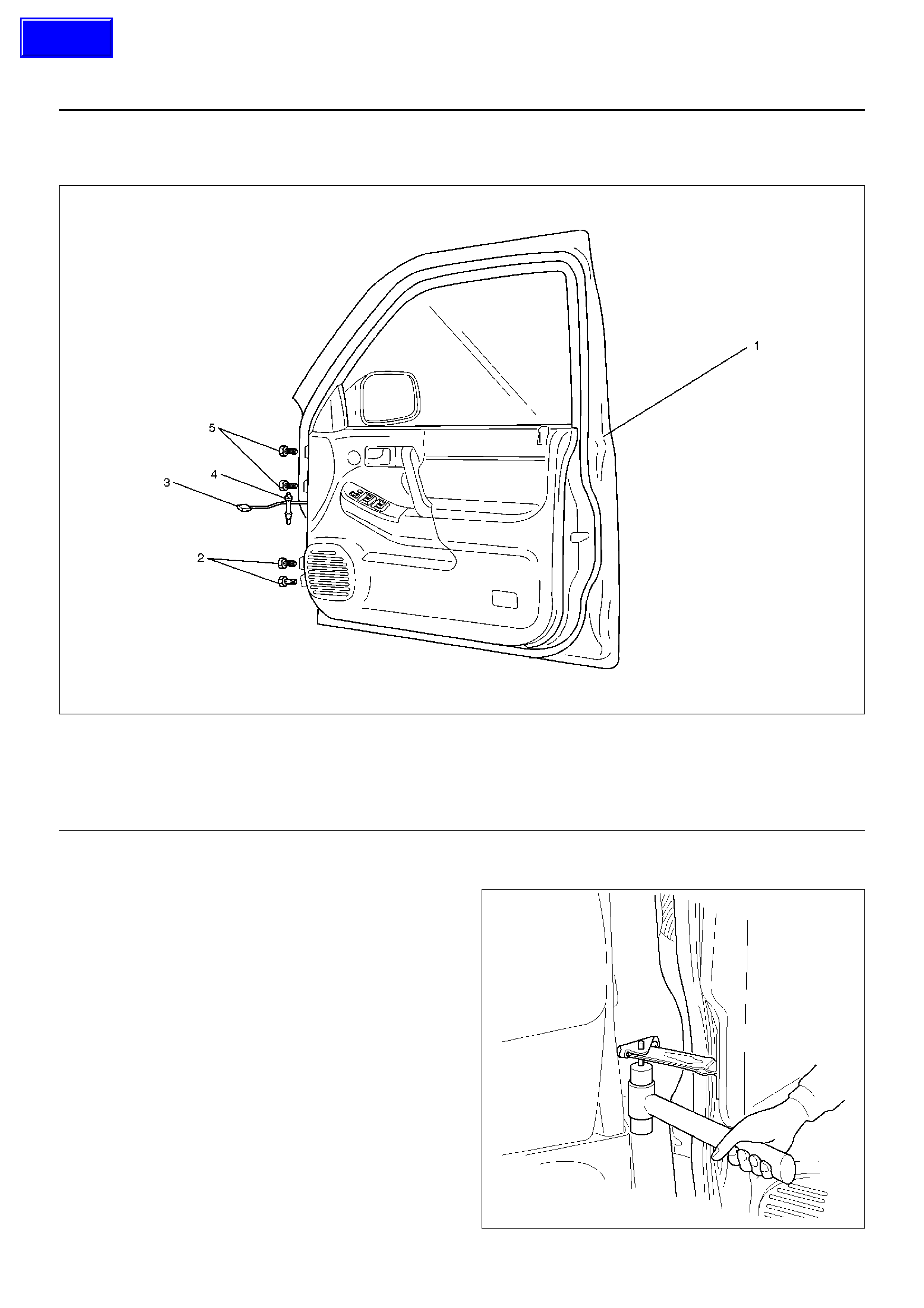
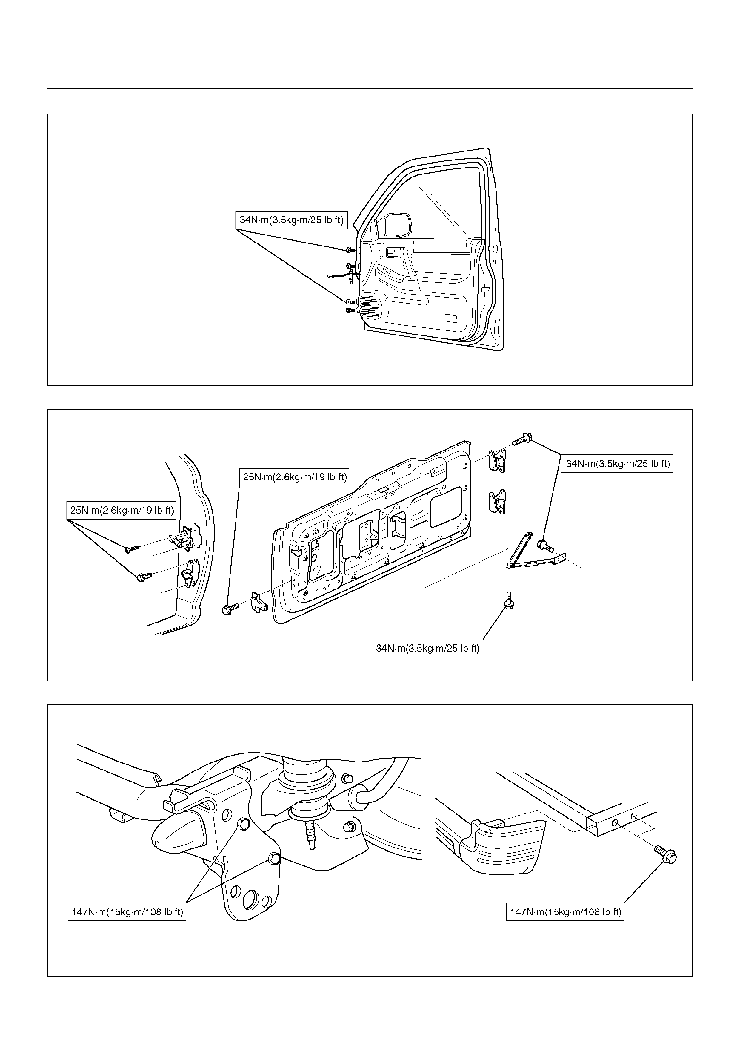
FRONT DOOR ASSEMBLY
PARTS LOCATION
630RW044
Legend
EndOFCallout
REMOVAL
1. Disconnect the battery ground cable.
2. Apply a setting mark on the body side hinge.
3. Remove the door check arm pin.
630RW001
(1) Front Door Assembly
(2) Lower Hinge Bolt
(3) Door Harness Connection
(4) Door Check Arm Pin
(5) Upper Hinge Bolt
Techline
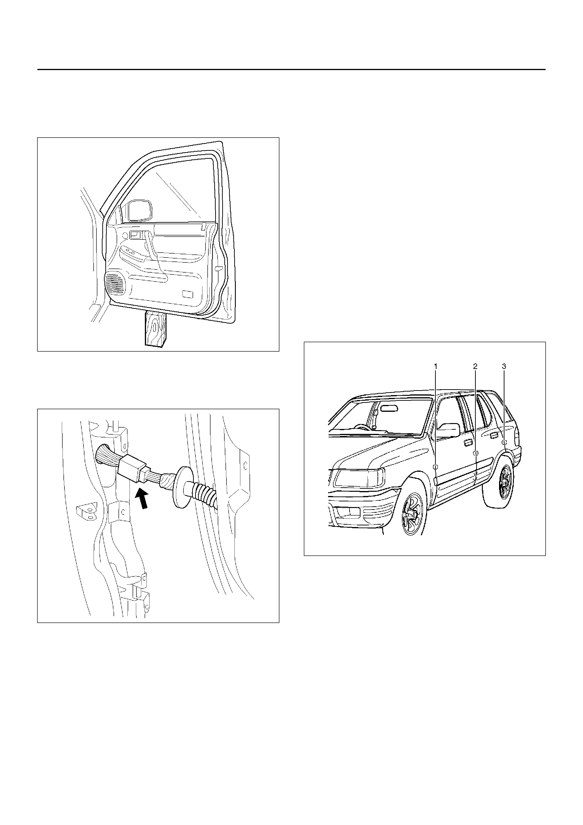
4. Remove the upper and lower hinge bolts.
• Position a wood block under the door for
protection and support the door assembly with
hands during removal or installation.
635RW003
5. Remove the door harness connection.
• Pull the door harness grommet out in order to
disconnect the harness connection.
630RW004
6. Remove the front door assembly.
INSTALLATION
To install, follow the removal steps in the reverse order,
noting the foll owi ng poi nts:
1. Align the door fitting to the body.
• Check the fender and front door (1).
Clearance: 5.0 mm (0.196 in)
Height (step): Flush
• Check the front door and rear door (2).
Clearance: 6.0 mm (0.23 in)
Height (step): Flush
• Check the rear door and body (3).
Clearance: 5.0 mm (0.196 in)
Height (step): Flush
Adjust clearance with door hinges.
Adjust height (step) by tapping on the fender
lightly with a rubber hammer.
610R100002
2. Tighten the door hinge bolts to the specified torque.
Torque : 34 N·m (3.5 kg·m/25 lb ft)
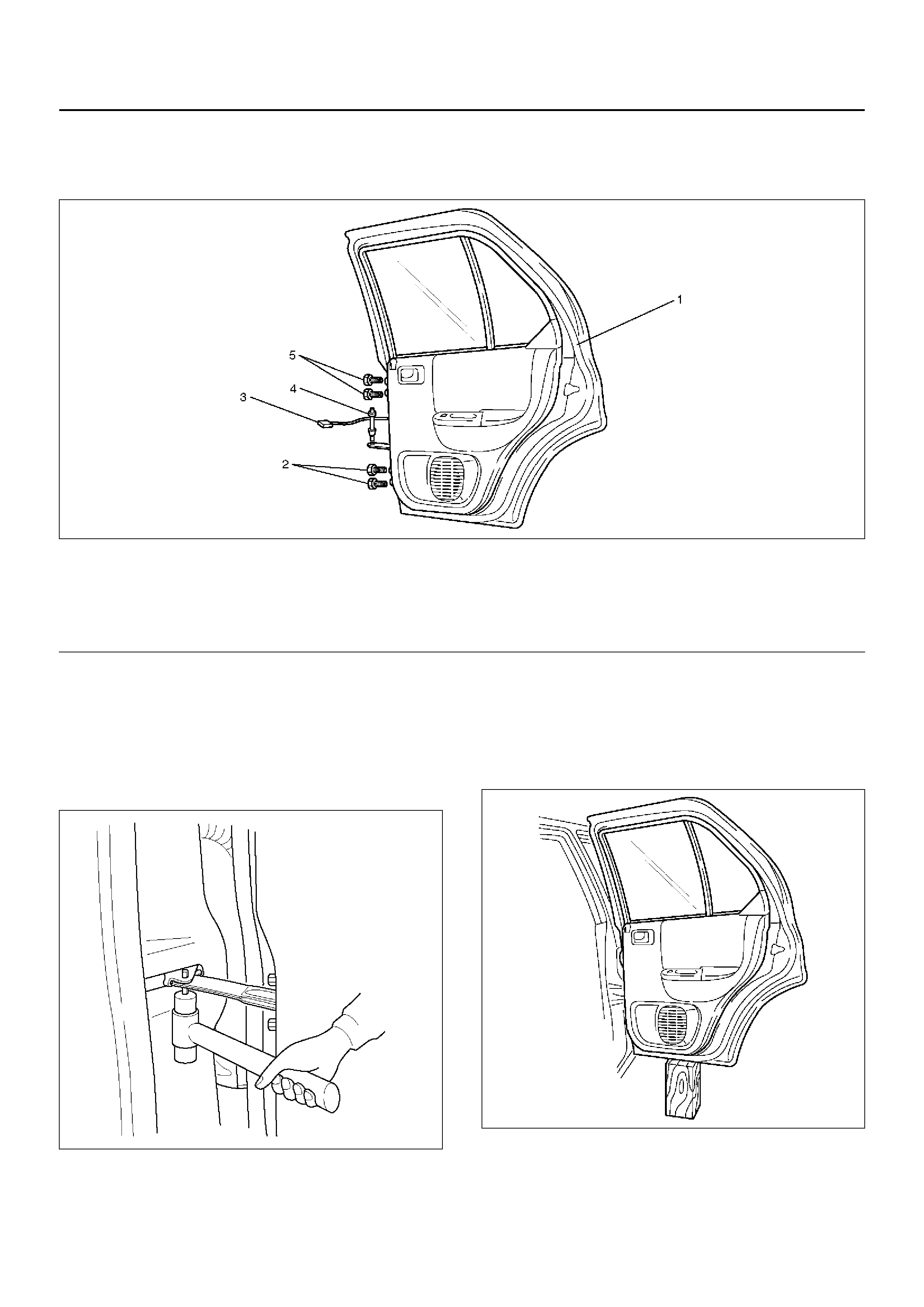
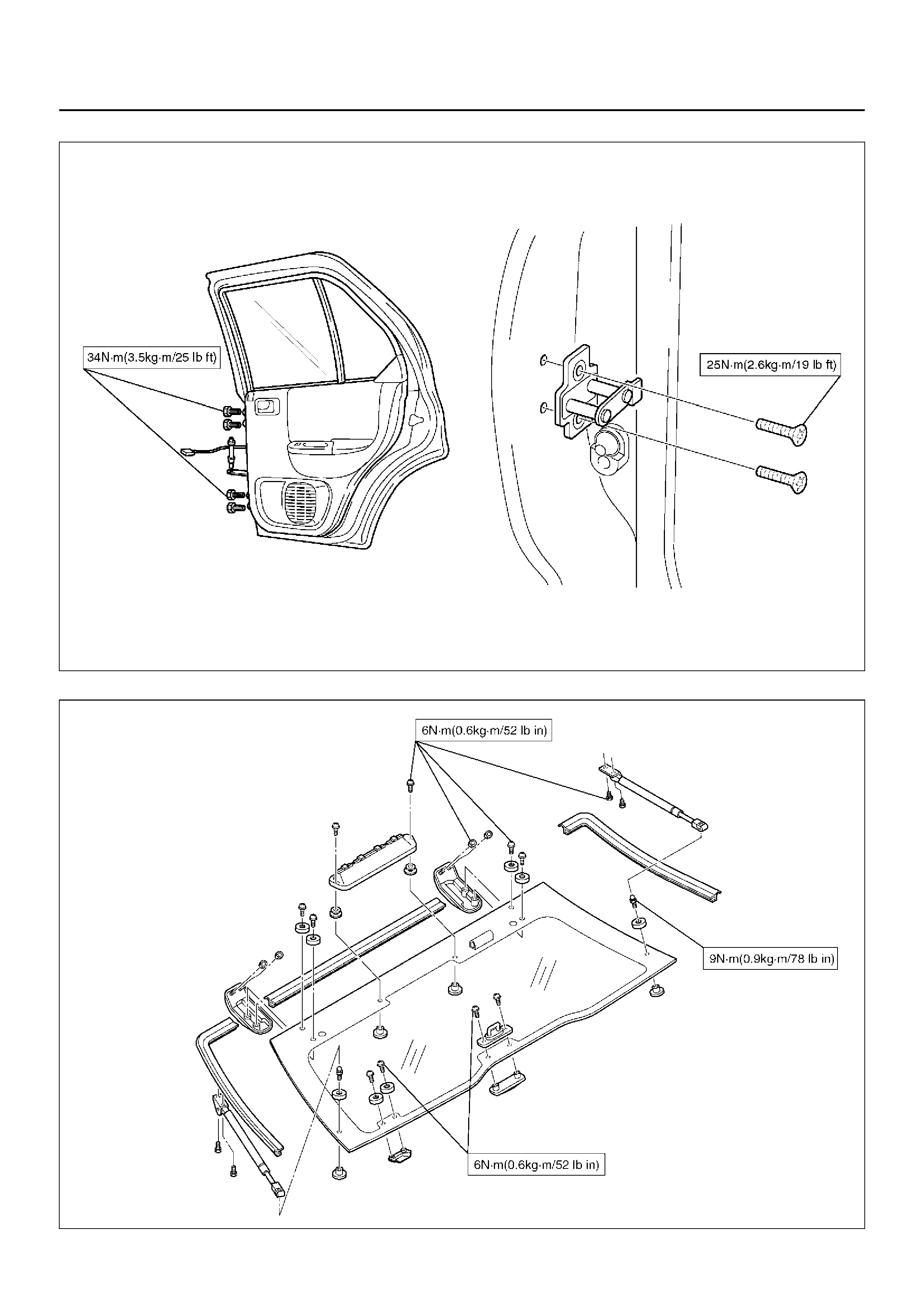
REAR DOOR ASSEMBLY
PARTS LOCATION
650R100001
Legend
EndOFCallout
REMOVAL
1. Disconnect the battery ground cable.
2. Apply a setting mark on the body side hinge.
3. Remove the door check arm pin.
630RW003
4. Remove the upper and lower hinge bolts.
• Position a wood block under the door for
protection and suppo rt the door assem bly with
hands during removal or installation.
650R100002
(1) Rear Door Assembly
(2) Lower Hinge Bolt
(3) Door Harness Connection
(4) Door Check Arm Pin
(5) Upper Hinge Bolt
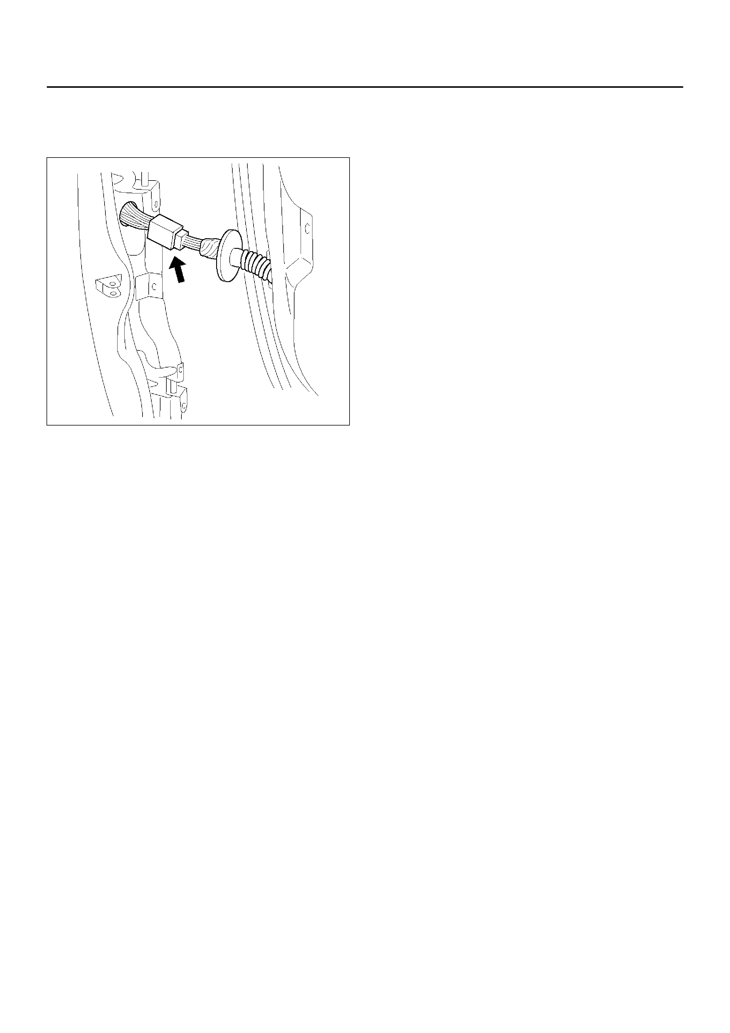
5. Remove the door harness connection.
• Pull the door harness grommet out in order to
disconnect the door harness connection.
630RW004
6. Remove the rear door assembly.
INSTALLATION
To install, follow the removal steps in the reverse order,
noting the following points:
1. Align the door fitting to the body by referring to Front
Door Assembly in this section.
2. Tighten the door hinge bolts to the specified torque.
Torque : 34 N·m (3.5 kg·m/25 lb ft)
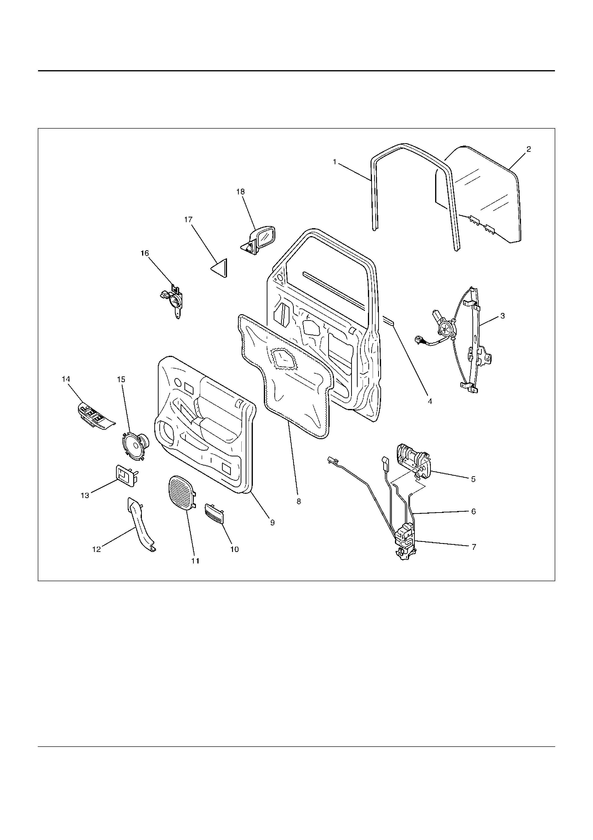
FRONT WINDOW REGULATOR, GLASS AND GLASS RUN
PARTS LOCATION
635RY00011
Legend
EndOFCallout
(1) Glass Run
(2) Glass
(3) Window Regulator
(4) Waist Seal
(5) Outside Handle
(6) Locking Link
(7) Door Lock A ssembly
(8) Waterproof Sheet
(9) Door Trim Panel
(10) Cour tesy Lig ht Lens
(11) Speaker Grille
(12) Grip Cover
(13) Inside Handle
(14) Power Window Switch
(15) Speaker Assembly
(16) Tweeter
(17) Door Mirror Cover
(18) Door Mirror Assembly
REMOVAL
1. Disconnect the battery ground cable.
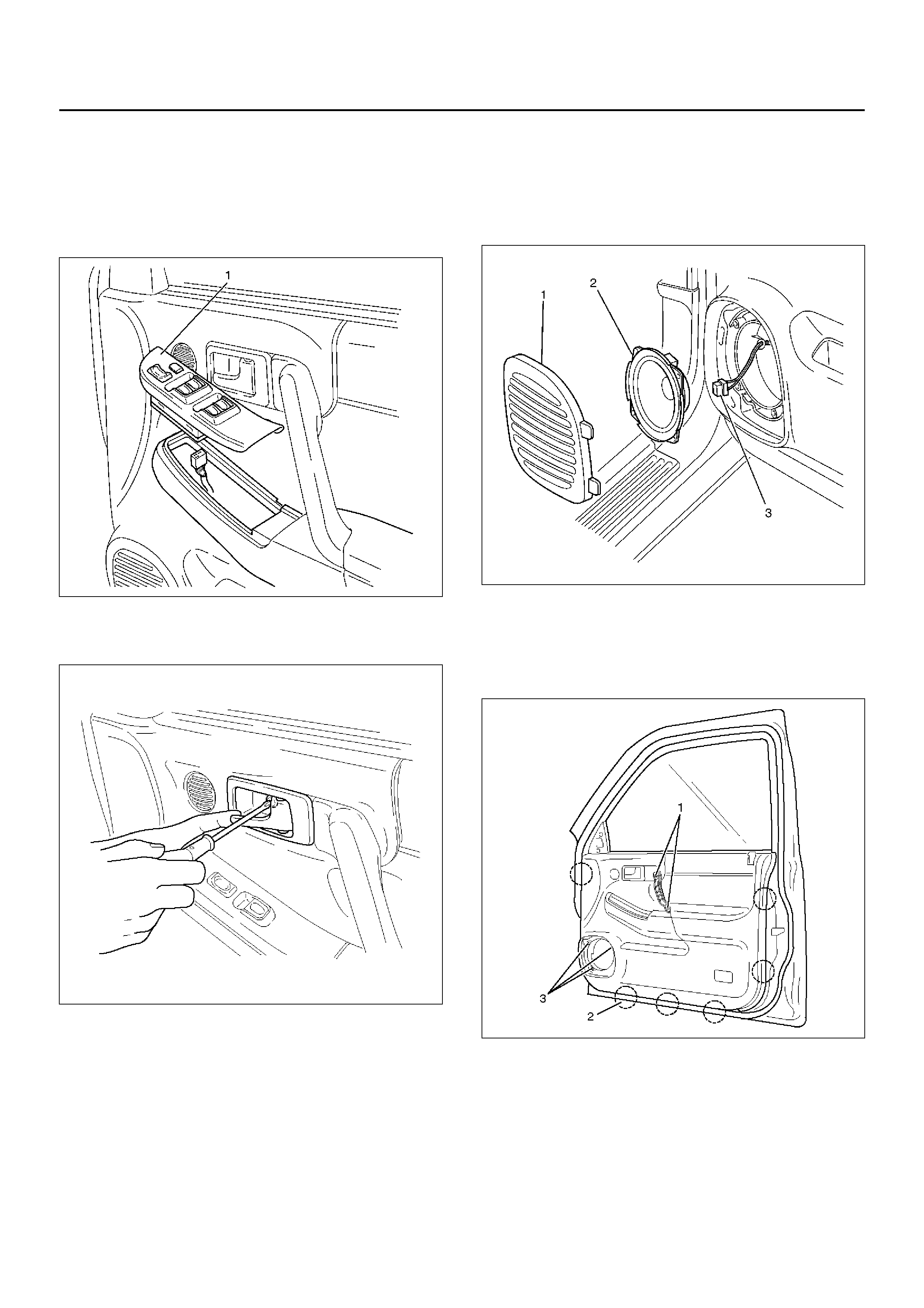
2. Remo ve the powe r window swi tch .
• Pry out the power window switch and remove the
connectors.
635RW016
3. Remove the screw while pulling the inside lever
toward you and then remove the inside handle.
632RW003
4. Remove the speaker grille (1).
• Pull out the front side of the grille.
5. Remove the speaker assembly (2).
• Remove the four screws and disconnect the
speaker harness connector (3).
890RX012
6. Remove the door mirror cover.
7. Remove the grip cover.
8. Remove the five screws (1), (3) and pull out the trim
panel at the six clip positions (2).
635RW007
9. Remove the waterproof sheet.
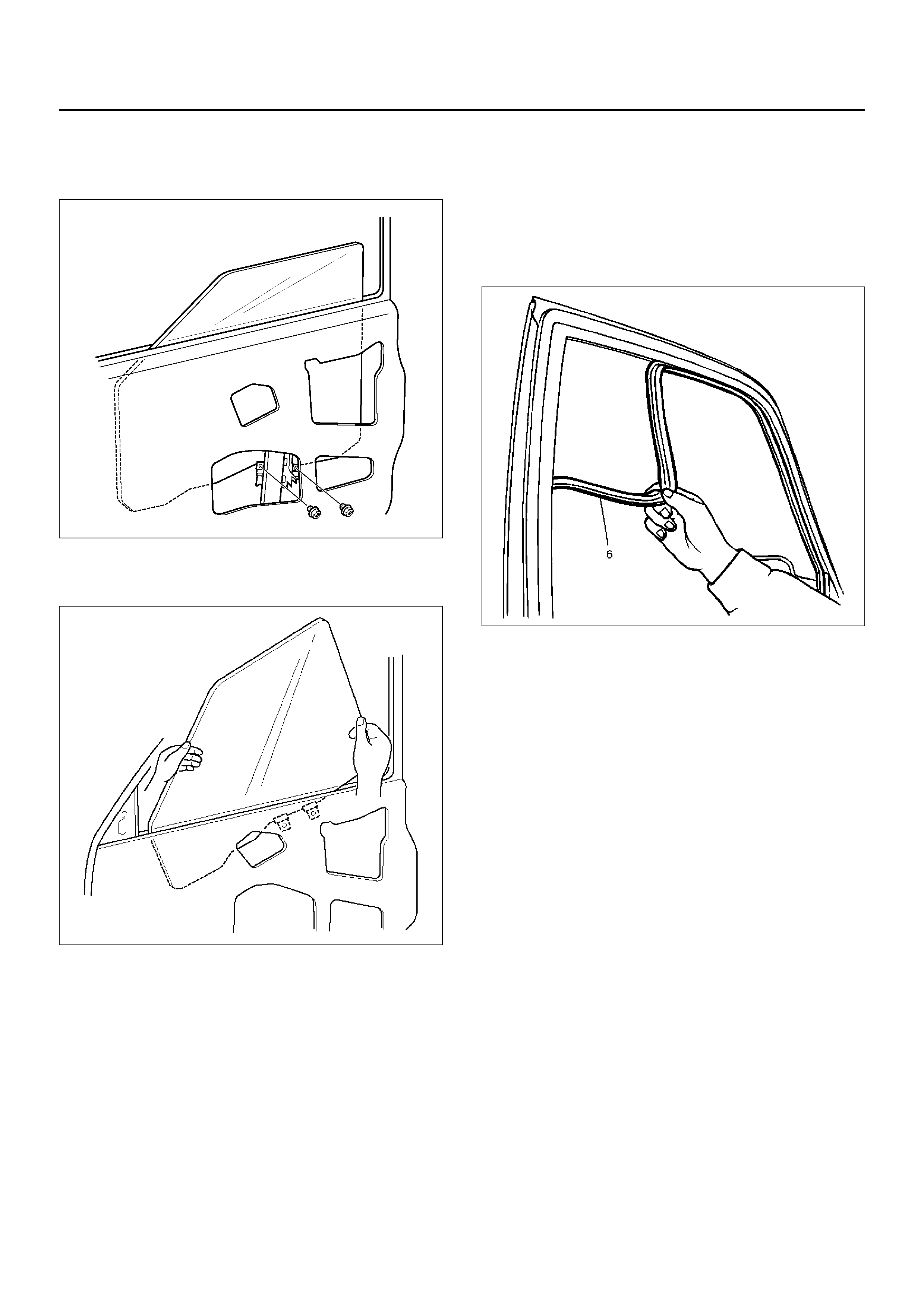
10. Remove the two bolts through the access hole and
pull out the glass upward.
631R100001
11. Turn the glass inside out and pull it up from its rear
side.
631RW007
12. Remove the window regulator.
• Remove the seven fixing bolts.
• Disconnect the window regulator motor harness
connector.
13. Remove the glass run.
• Pull the glass run (6) out from the door frame
groove.
631RS007
INSTALLATION
To install, follow the removal steps in the reverse order,
noting the foll owi ng poi nts:
1. Check to see that the window regulator operates
smoothly and the glass opens and closes properly.
2. Install the waterproof sheet with no clearance
between the door panel and the waterproof sheet.
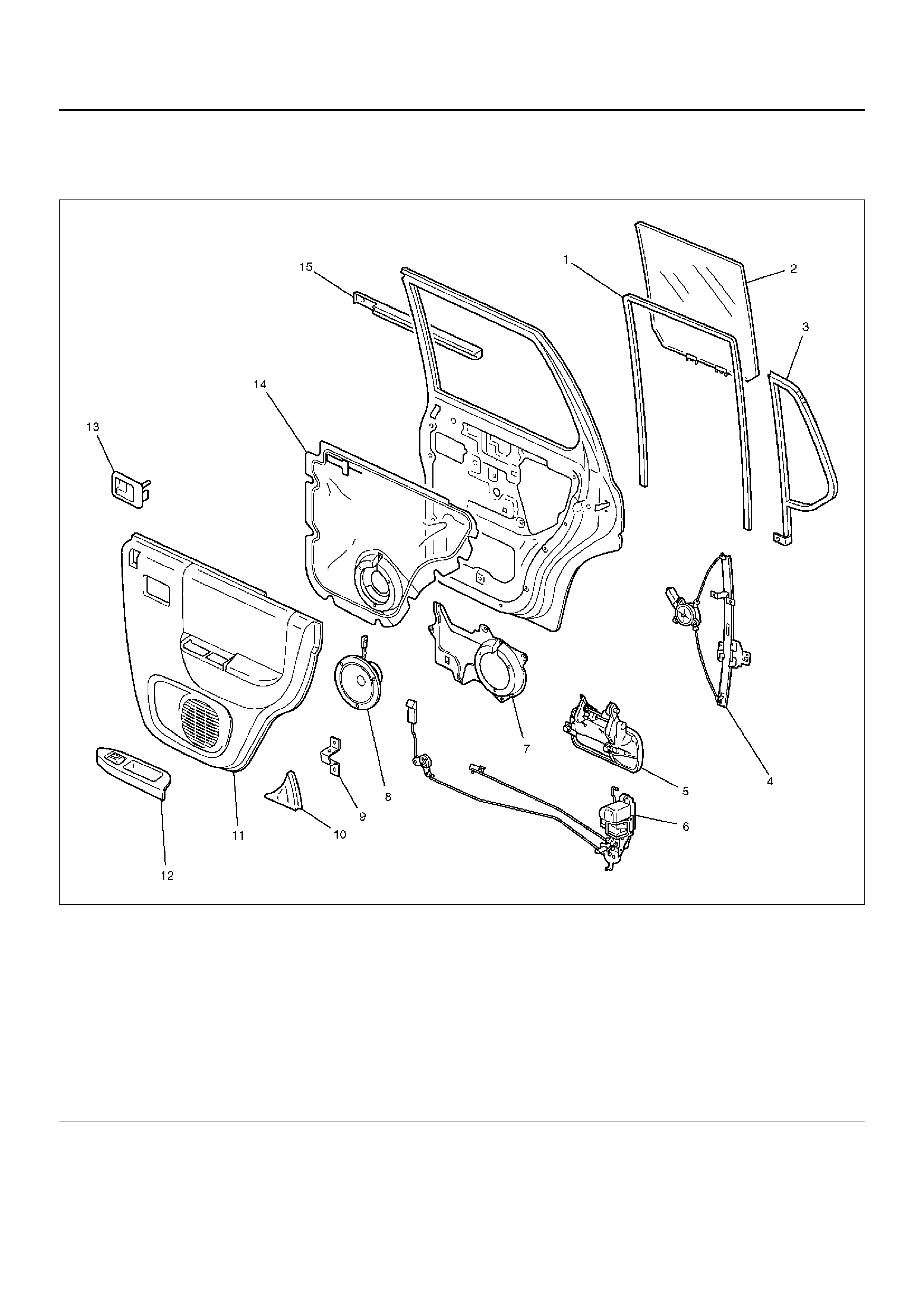
REAR WINDOW REGULATOR, GLASS AND GLASS RUN
PARTS LOCATION
655R100005
Legend
EndOFCallout
(1) Glass Run
(2) Glass
(3) Fixed Glass
(4) Window Regulator
(5) Outside Handle
(6) Door Lock A ssembly
(7) Spea ke r Br ac ke t
(8) Speaker
(9) Bracket
(10) Rear Corner Garnish
(11) Door Trim Panel
(12) Power Window Switch and Pull Case
(13) Inside Handle
(14) Waterproof Sheet
(15) Waist Seal
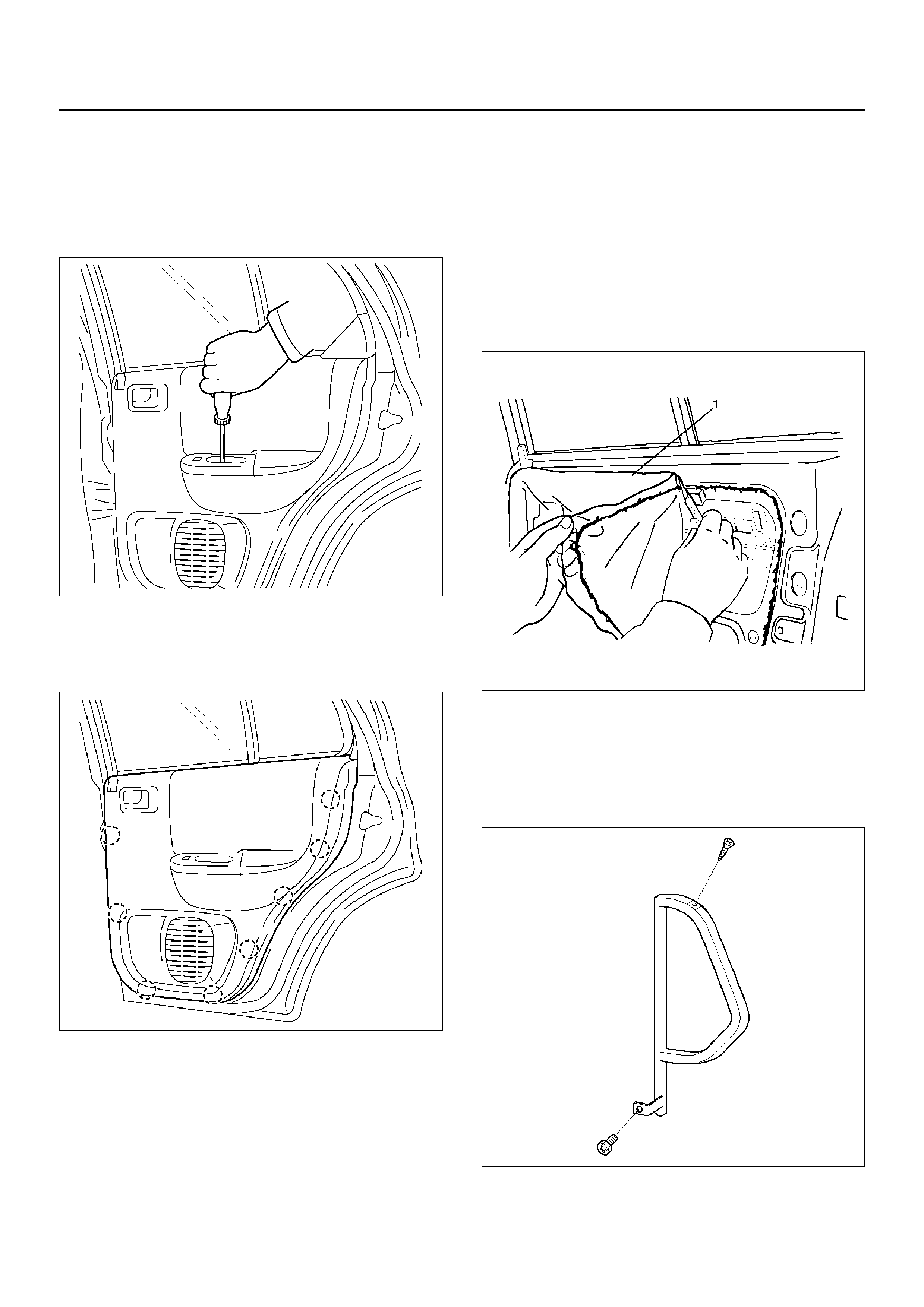
REMOVAL
1. Disconnect the battery ground cable.
2. Remove the screw while pulling the inside lever
toward you and then remove the inside handle.
3. Remove the one screw at the pull case.
655R100002
4. Remo ve the re ar cor ner garnis h.
5. Pull out the trim panel at the eight clip positions.
• Disconnect the power window switch connector.
655R100003
6. Remove the power window switch and pull case.
• Remove the fixing screws from back side of the
rear door trim panel.
7. Remove the bracket.
8. Disconnect the speaker harness connector.
9. Remove the speaker with the speaker harness
connector from the door inner panel.
10. Remove the waterproof sheet (1).
• Taking notice of the door harness, peel the
waterproof sheet off the door panel carefully.
651RS002
11. Remove the speaker bracket.
• Remove the six fixing screws.
12. Remove the fixed glass.
• Remove one bolt and screw as shown in the
figure, then pull it upward.
651RW002
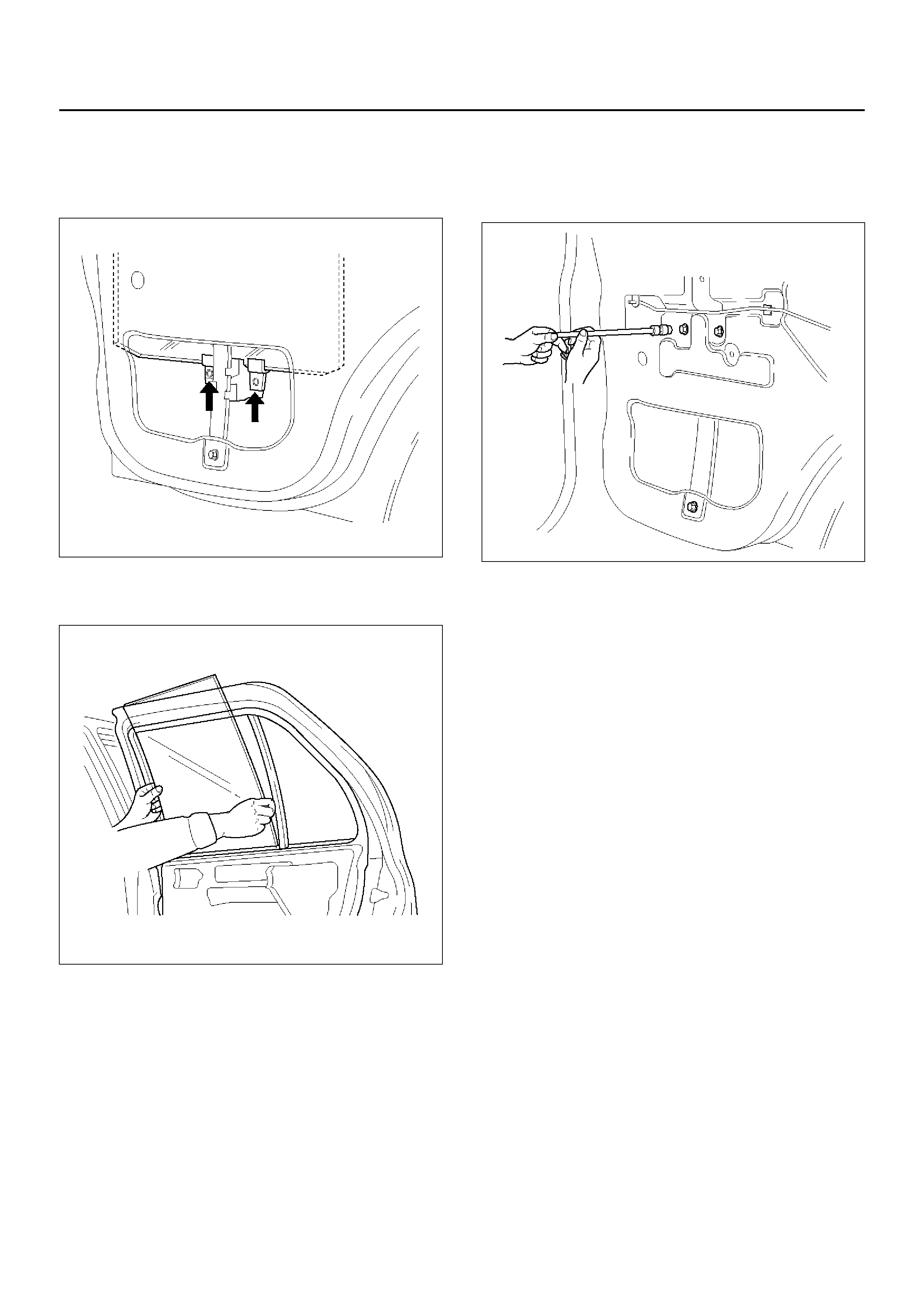
13. Remove the glass.
• First, align the height of regulator to the access
hole. Remove two screws attaching bottom
channel and regulator, then remove the glass.
651RW006
• Remove the window glass by tilting it as
necessary.
651RW007
14. Remove the window regulator.
• Remove the six fixing bolts and pull the regulator
out from the lower hole of the door panel.
• Disconnect the connector.
651RW005
15. Remove the glass run.
• Pull the glass run out from the door frame.
INSTALLATION
To install, follow the removal steps in the reverse order,
noting the foll owi ng poi nts:
1. Check to see that the window regulator operates
smoothly and the glass opens and closes properly.
2. Install the waterproof sheet with no clearance
between the door panel and the waterproof sheet.
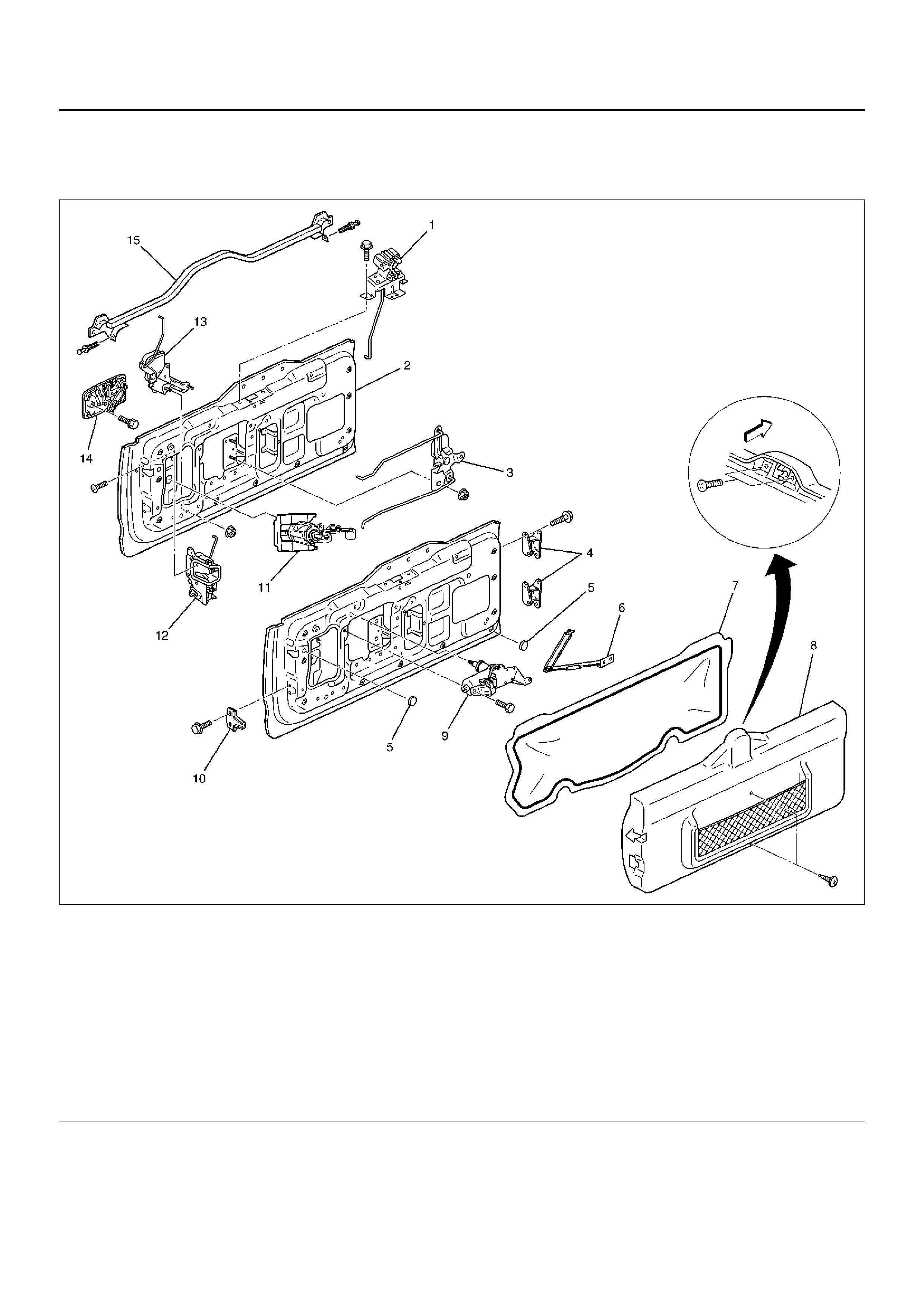
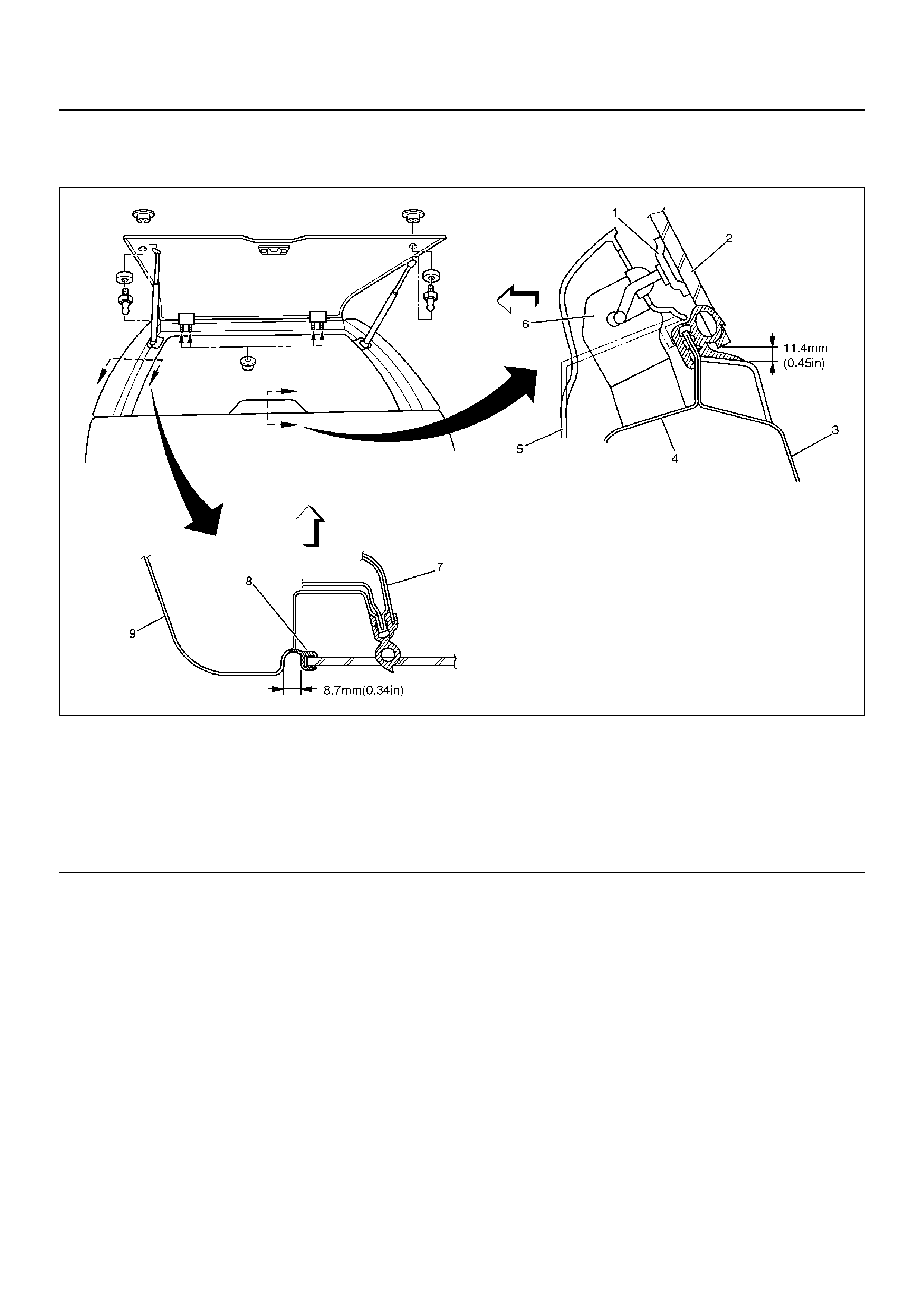
TAILGATE
PARTS LOCATION
681RW010
Legend
EndOFCallout
(1) Hatchgate Lock Assembly
(2) Tailgate Assembly
(3) Tailgate Bell Crank
(4) Hinges
(5) Plug
(6) Tailgate Stopper Link
(7) Waterproof Sheet
(8) Trim Cover Asse mbly
(9) Rear Wiper Motor
(10) Dove Tail
(11) Key Cylinder
(12) Tailgate Lock Assembly
(13) Hatchgate Lock Actuator Assembly
(14) Outside Handle
(15) Tailgate Waist Seal
REMOVAL
1. Disconnect the battery ground cable.
2. Remove the tailgate trim cover assembly (3).
• Remove the two screws (2) holding the hatchgate
lock assembly (1) first and the two screws fixing
the trim cover assembly. Pull up the trim cover
while detaching the clips from tailgate panel.
683RW001
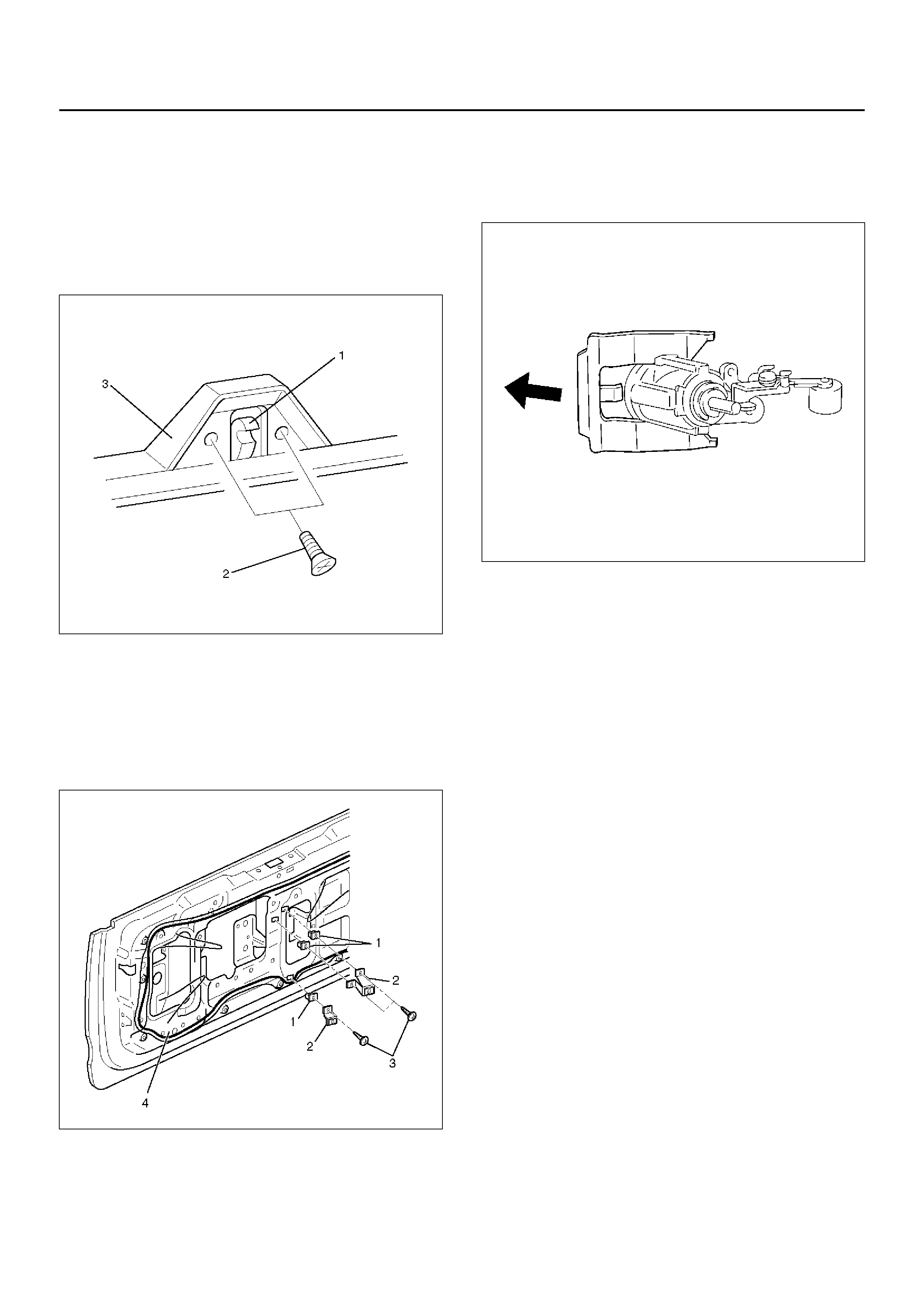
3. Remove the tailgate trim brackets (2).
• Remove the three fixing screws (3) and screw
grommets (1).
4. Remove the waterproof sheet (4).
• Remove the waterproof sheet, taking special care
so as not to break it.
681RW014
5. Remove the hatchgate lock.
• Disconnect the lock link and connector and
remove the three fixing bolts.
6. Remove the key cylinder.
• Disconnect the locking links.
• Remove the key cylinder retaining clip with
screwdriver to remove the key cylinder.
683RW025
7. Remove the hatchgate lock actuator assembly.
• Disconnect the actuator harness connector.
• Remove the two nuts holding hatchgate lock
actuator assembly from inside.
8. Remove the outside handle.
• Remove the two bolts holding the outside handle
from inside.
9. Remove the tailgate lock assembly.
• Remove the three screws holding the lock
assembly.
10. Remove the dove tail.
11. Remove the tailgate locking links.
12. Remove the rear wiper arm.
• Refer to Rear Wiper Arm/Blade in Wiper/Washer
System se cti on.
13. Remove the rear wiper motor.
14. Remove the tailgate harness cable.
15. Remove the spare tire carrier.
• Refer to Spare Tire Carrier in this section.
16. Remove the tailgate stopper link.
17. Remove the tailgate assembly.
• Remove the tailgate assembly, taking care so as
not to damage the hinge. Tailgate assembly is
heavy and removal operation require two people.
18. Remove the tailgate waist seal.
INSTALLATION
To install, follow the removal steps in the reverse order,
noting the following points:
1. When setting up links, pay attention to the position
and direction of the links.
683RW003
Legend
EndOFCallout
2. T ighten the t ailgate hinge fixing bolts to the specified
torque.
Torque: 34 N·m (3.5 kg·m/25 Ib ft)
3. Tighten the tailgate stopper link fixing bolts to the
specified torque.
Torque: 34 N·m (3.5 kg·m/25 Ib ft)
4. Tighten the dove tail fixing bolts to the specified
torque.
Torque: 25 N·m (2.6 kg·m/19 Ib ft)
(1) Tailgate Lock Link
(2) Outside Handle
(3) Key Cylinder Lock Link
(4) Cancel Mechanism
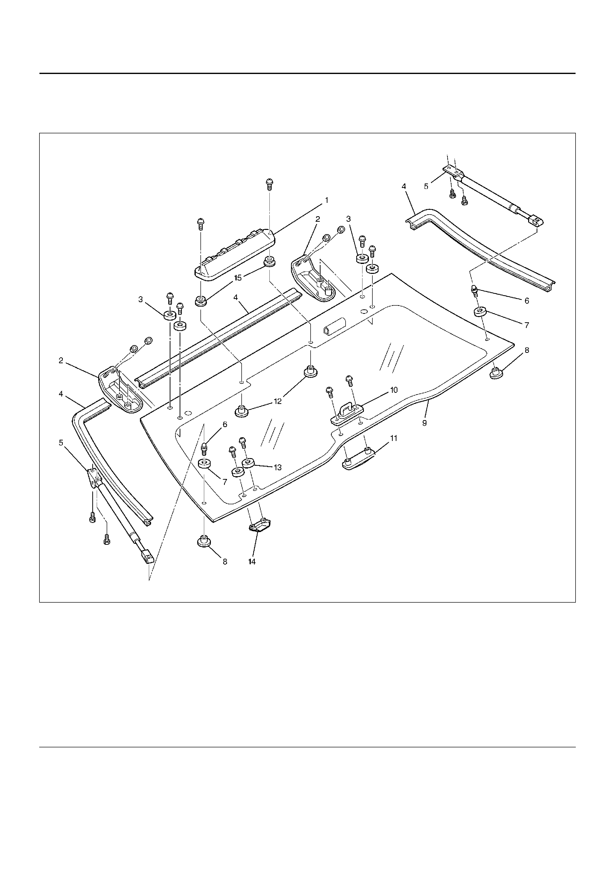
REAR HATCHGATE
PARTS LOCATION
682RY00002
Legend
EndOFCallout
(1) High Mou nt Stoplight
(2) Hatchgate Hinge
(3) Hinge Collar
(4) Hatchgate Glass Seal
(5) Hatchgate Gas Stay
(6) Hatchgate Ball Stud
(7) Ball Stud Spacer
(8) Ball Stud Fastener
(9) Hatchgate Glass
(10) Hatchgate Striker
(11) St riker Fastener
(12) High Mount Stoplight Fastener
(13) Outside Handle Collar
(14) Outside Handle
(15) High Mount Stoplight Spacer
REMOVAL
1. Disconnect the battery ground cable.
2. Disconnect the high mount stoplight and rear
defogger harness connectors.
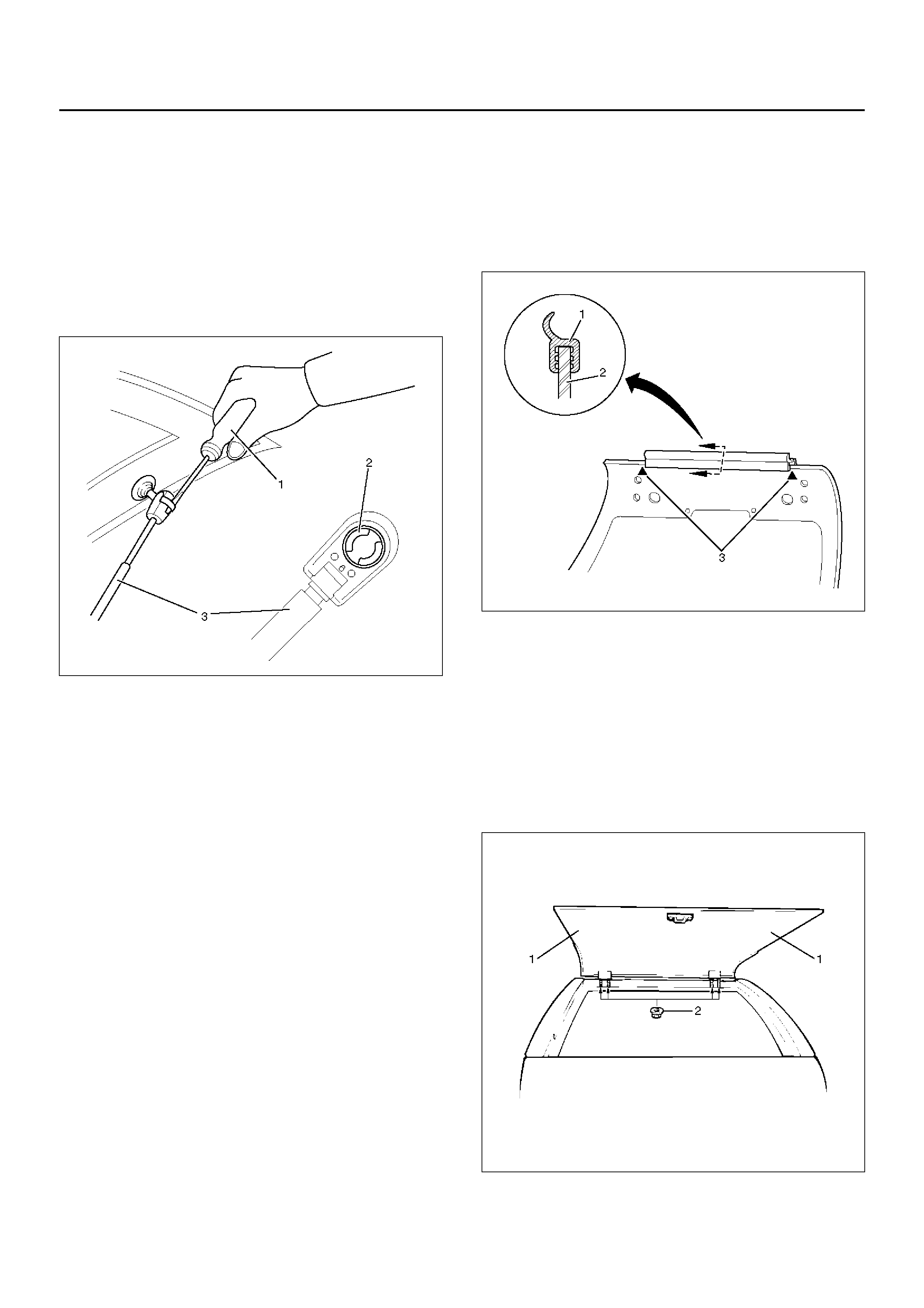
3. Remove the hatchgate ball stud (LH and RH).
• Remove gas stay fixing screw and pull up the gas
stay assembly (3) from the ball stud by spreading
the retainer (2) holding the ball stud at the end of
the gas stay with screwdriver (1), etc.
683RW004
4. Remove the hatchgate hinge nuts from body side.
5. Remove the hatchgate glass.
• When pulling down the hatchgate glass, exercise
special care so as not to damage it.
Hatchgate glass assembly is heavy and removal
operation requires the two people.
6. Remove the two screws to remove hatchgate striker
and fastener.
7. Remove the outside handle.
8. Remove the hinges.
9. Remove the high mount stoplight.
10. Remove the hatchgate finisher.
INSTALLATION
To install, follow the removal steps in the reverse order,
noting the following points.
1. Attach the upper seal (1) to the hatchgate glass (2)
indicated portion (3) so that the end of the glass
contacts the bottom of the upper seal.
682RW003
2. When installing the hatchgate glass, first attach the
hinge to the hatchgate glass. Align the stud of the
hinge to the hole at body while supporting the
hatchgate glass with two people at indicated
positions (1), and then partially tighten the hinge to
body nut (2).
After adjustment (refer to Adjustment in this section)
is completed, fully tighten the nut, hinge to body nut.
• Hatchgate hinge assembly for left and right sides
from each other.
682RW005
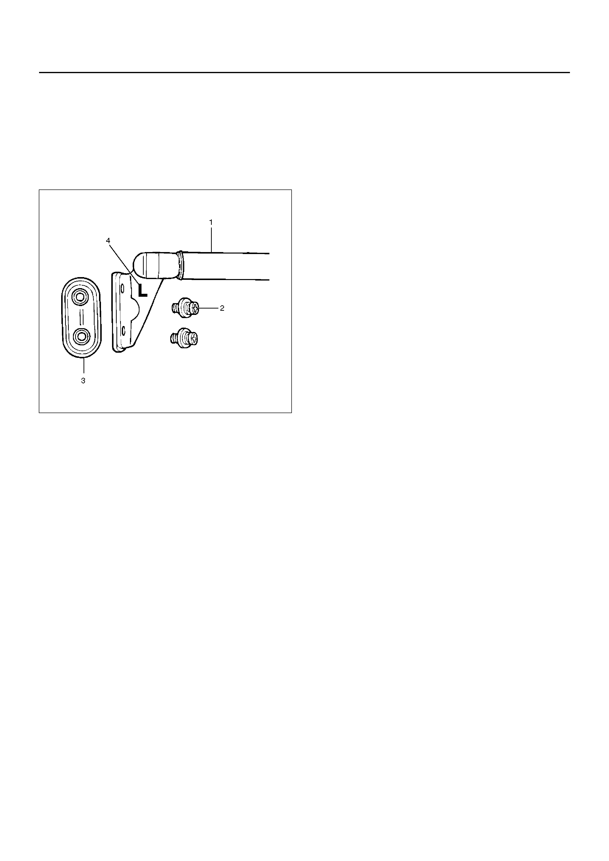
3. When installing gas stay assembly (1), first install
the gas stay onto the rear quarter panel with fixing
screw (2) and fastener (3) and then attach the gas
stay upper end to the ball stud by spreading the
retainer with screwdriver, etc. Gas stay assemblies
for left and right sides dif fer from each other (The
letter (4) L(LH) or R(RH) is embossed on the gas
stay assembly.)
683RW005
4. When installing hatchgate striker assembly, first
partially tighten the fixing screw and close the
hatchgate and tailgate. Then fully tighten the fixing
screw with the condition that the striker fits the
hatchgate lock assembly at the tailgate.
Make sure that clearance exists between hatchgate
striker and lock assembly.
After installation, again make sure that the striker
fits the lock assembly properly.
5. Tighten the nuts; hinge to body (LH and RH)
Torque : 6 N·m (0.6 kg·m/52 lb in)
6. T ighten the screws; glass and hinge fix (LH and RH)
Torque : 6 N·m (0.6 kg·m/52 lb in)
NOTE: When installing the hinge to the body, exercise
special care not to damage the body paint surface.
7. Tighten the hatchgate striker fixing screws.
Torque : 6 N·m (0.6 kg·m/52 lb in)
ADJUSTMENT
• Hatchgate alignment is obtained by moving
hatchgate hinges.
682RY00003
Legend
EndOFCallout
(1) Hatchgate Striker
(2) Hatchgate Glass
(3) Tailgate Outer Panel
(4) Tailgate Inner Panel
(5) Trim Cover
(6) Hatchgate Lock Assembly
(7) Quarte r Trim
(8) Hatchgate Glass Seal
(9) Quar te r Ou ter Panel
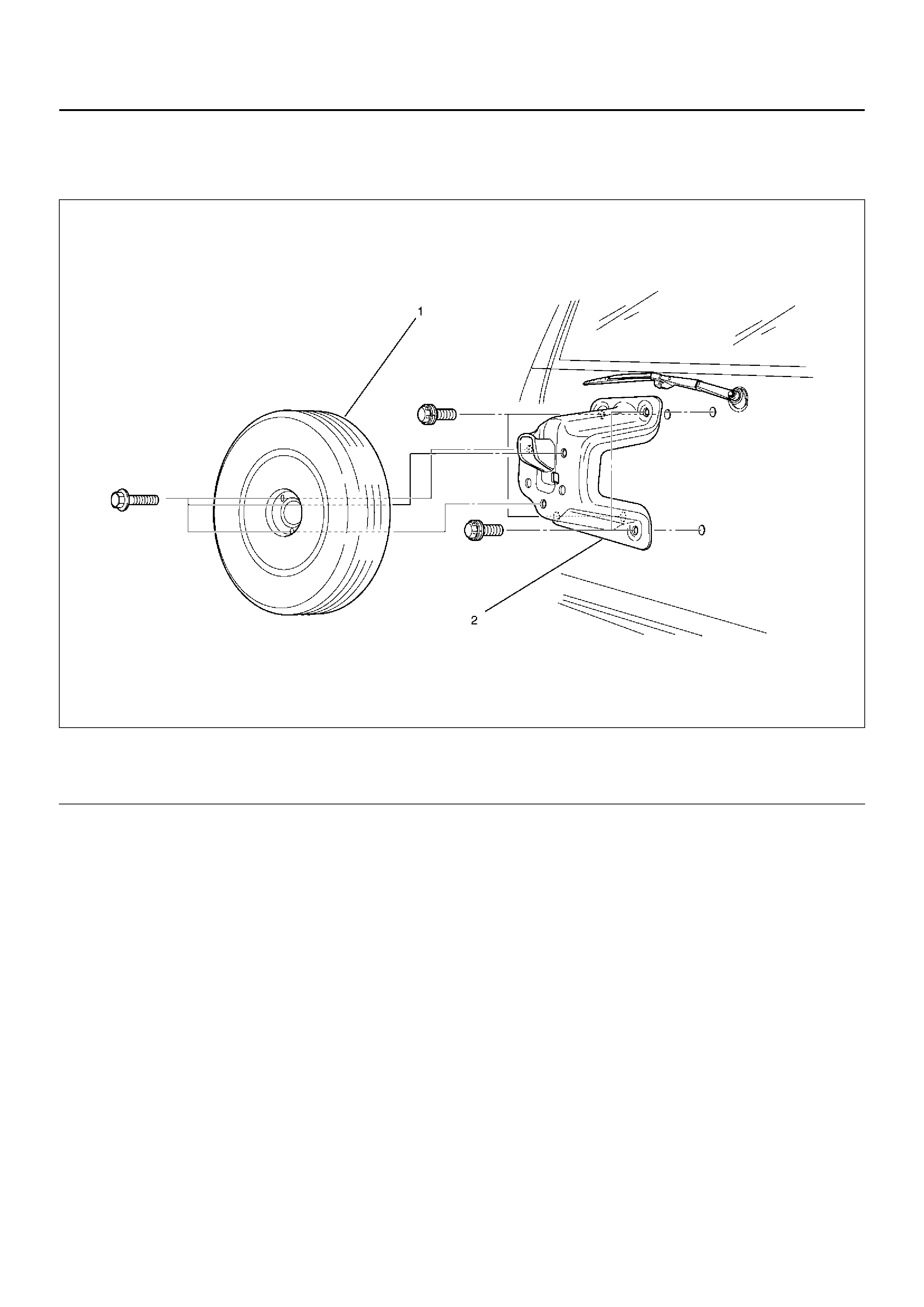
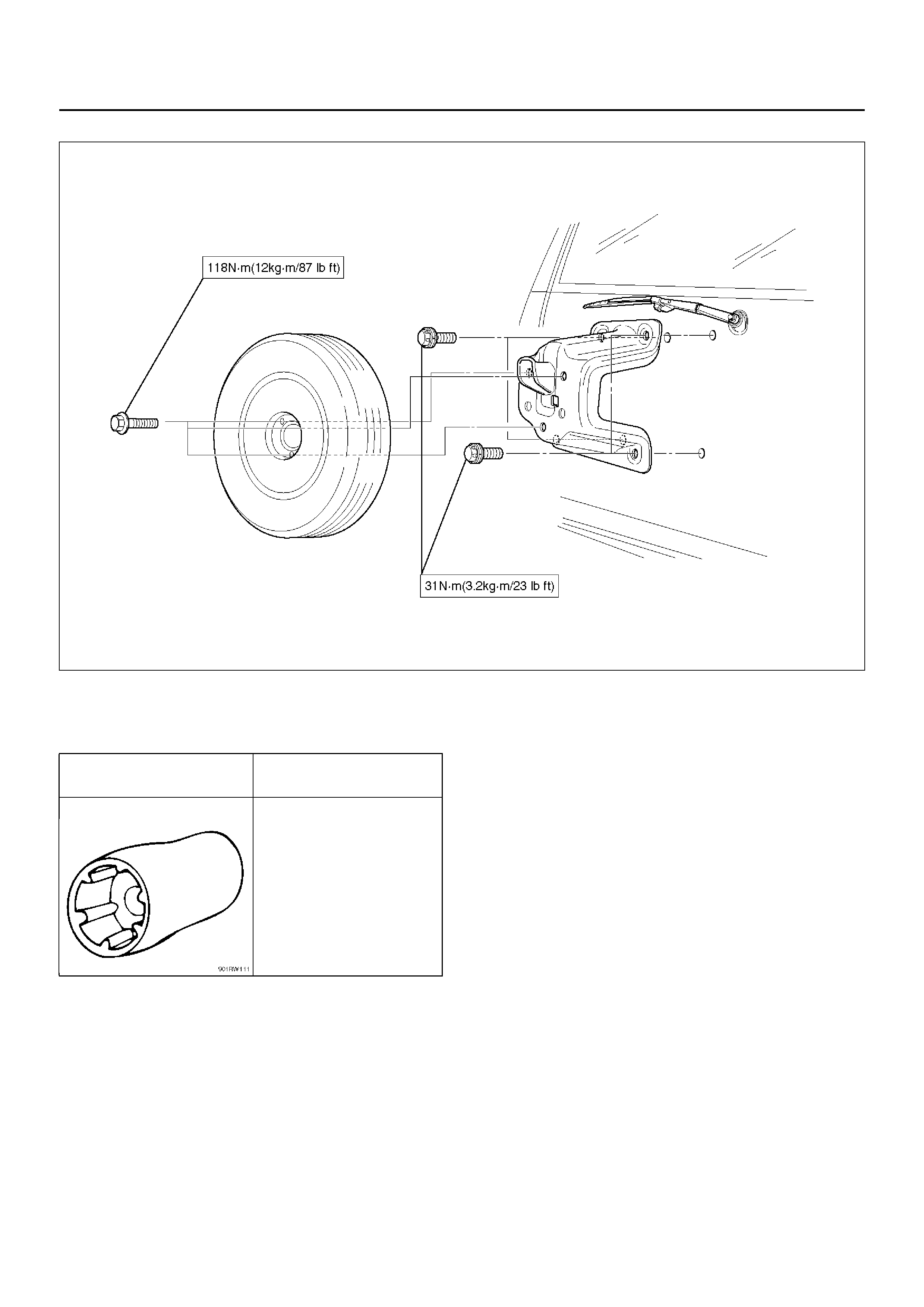
SPARE TIRE CARRIER
PARTS LOCATION
530RX005
Legend
EndOFCallout
REMOVAL
1. Remove the spare tire (1).
2. Remove the spare tire carrier (2) by using spare tire
carrier nut wrench 5–8840–2095–0 (J–34355).
INSTALLATION
1. Spare tire carrier.
• Tighten the carrier fixing bolts to the specified
torque.
Torque : 31 N·m (3.2 kg·m/23 lb ft)
2. Spare tire
• Tighten the spare tire fixing bolts to the specified
torque.
Torque : 118 N·m (12.0 kg·m/87 lb ft)
(1) Spare Tire
(2) Spa re Tire Carrier
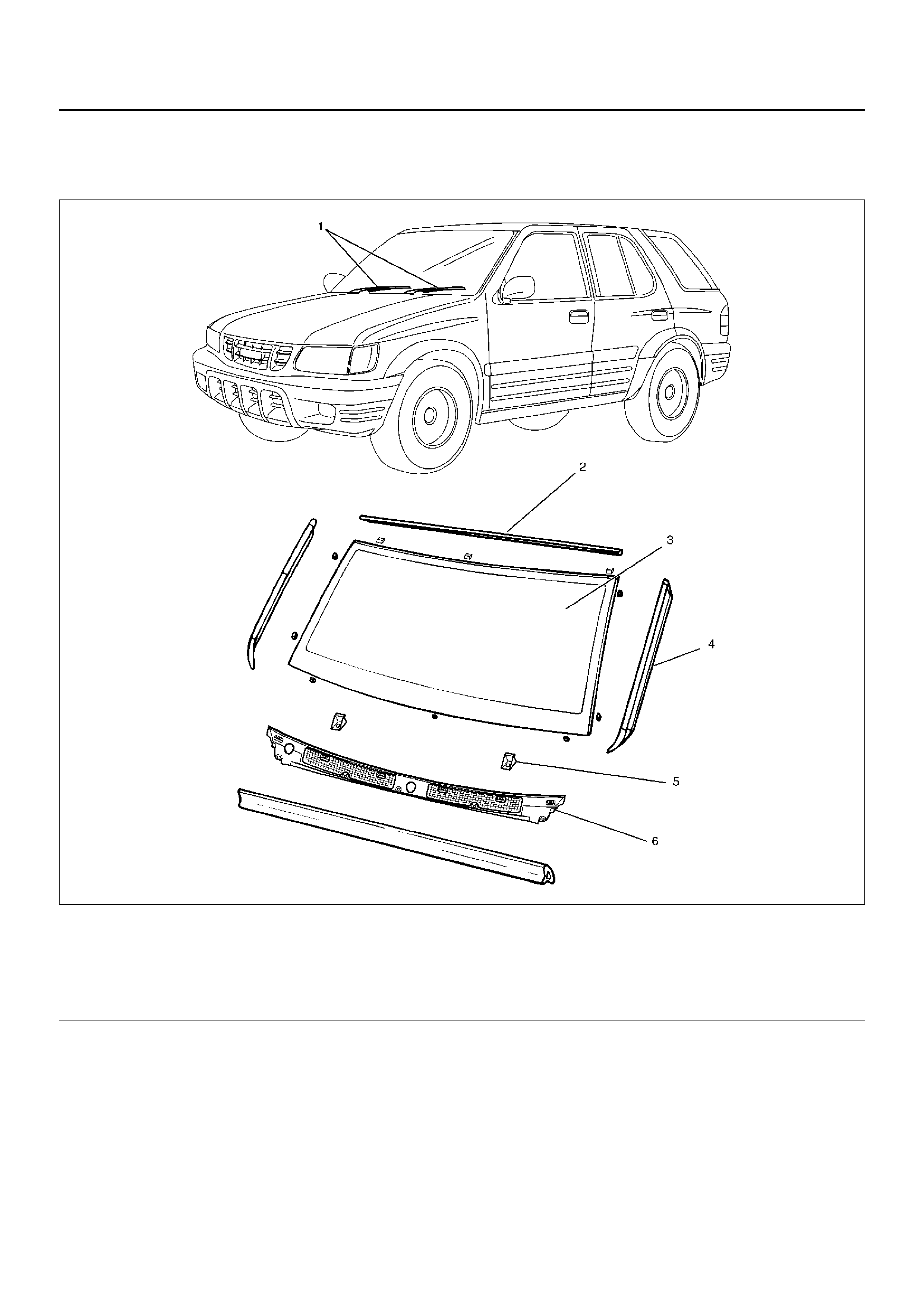
WINDSHIELD
PARTS LOCATION
607RY00005
Legend
EndOFCallout
REMOVAL
1. Disconnect the battery ground cable.
2. Remove the front pillar trim cover.
• Turn up the finisher and pry the trim cover clips
free from the body panel.
3. Remove the sunvisors and sunvisor holders.
• Refer to Headlining in Exterior/Interior Trim
section.
4. Remove the interior mirror.
• Refer to Interior Mirror Assembly in Exterior/
Interior Trim section.
5. Remove the windshield wiper arm.
• Refer to Windshield Wiper Arm/Blade in Wiper/
Washer System section.
6. Remove the windshield side moulding.
(1) Windshield Wiper Arm
(2) Windshield Upper Moulding
(3) Windshield
(4) Windshield Side Moulding
(5) Windshield Support
(6) Front Cowl Cover
• Pull the moulding out from drip rail.
7. Remove the front cowl cover.
8. Remove the windshield support.
9. Remove the upper moulding.
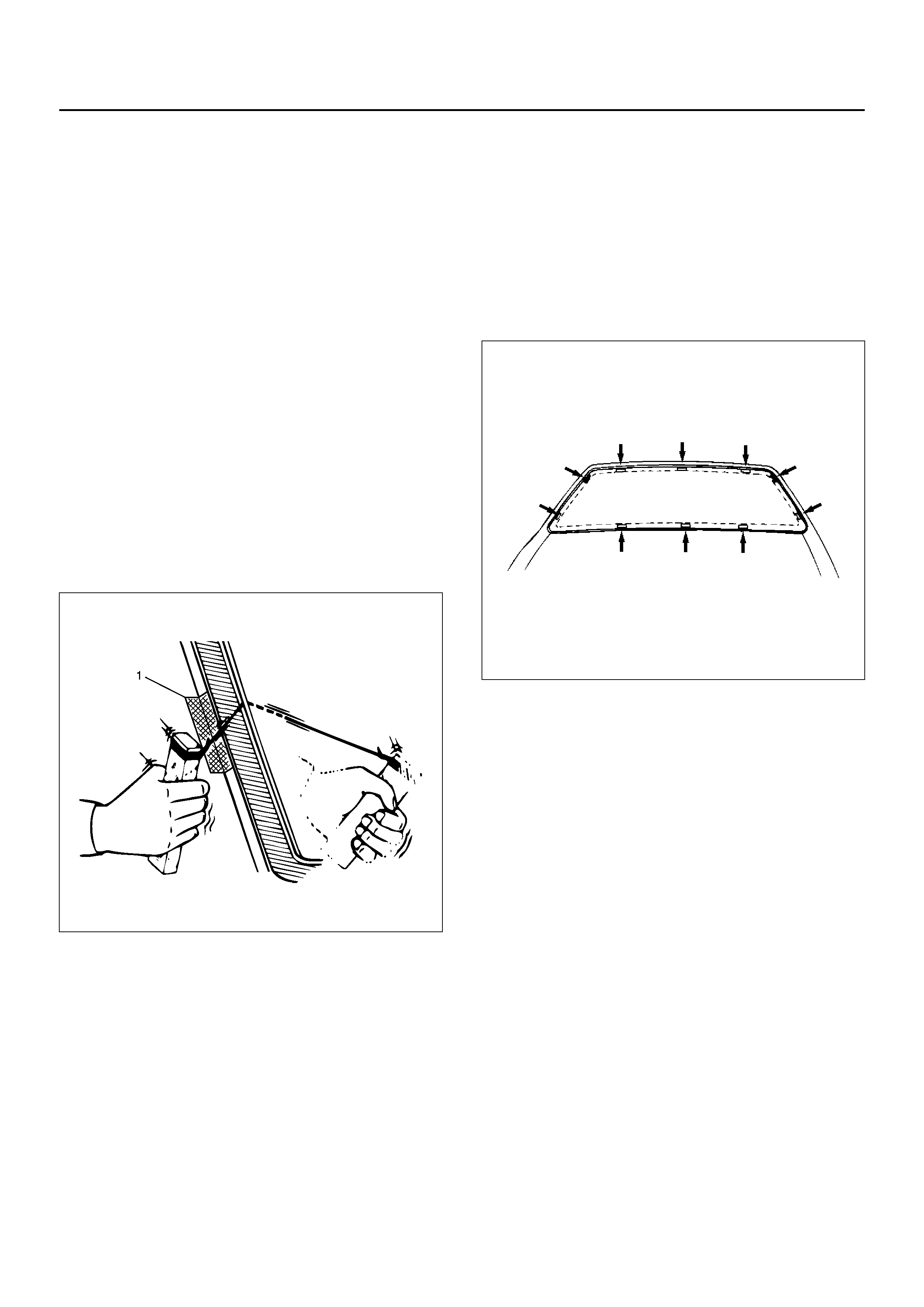
10. Remove the windshield.
• Use a knife to cut through part of the adhesive
caulking material.
• Secure one end of a piece of steel piano wire
(0.02 inches in diameter) to a piece of wood that
can serve as a handle.
• Use a pair of needle nose pliers to insert the other
end of the piano wire through the adhesive
caulking material at the edge of the windshield
glass.
• Secure the other end of the piano wire to another
piece of wood.
• With the aid of an assistant, carefully move the
piano wire with a sawing motion to cut through
the adhesive caulking material around the entire
circumference of the windshield glass.
• Attach some cloth tape (1) on the body for
protecting the painting surface.
607RW012
• Clean the remaining adhesive caulking material
from the area of the body which holds the
windshield.
INSTALLATION
To install, follow the removal steps in the reverse order,
noting the foll owi ng poi nts.
1. Clean the bonding surfaces of both the windshield
and body panel with a soft rag and white gasoline.
2. Install the spacer.
• Attach spacers in ten locations as shown in the
figure.
• Always use new spacer.
607RW004
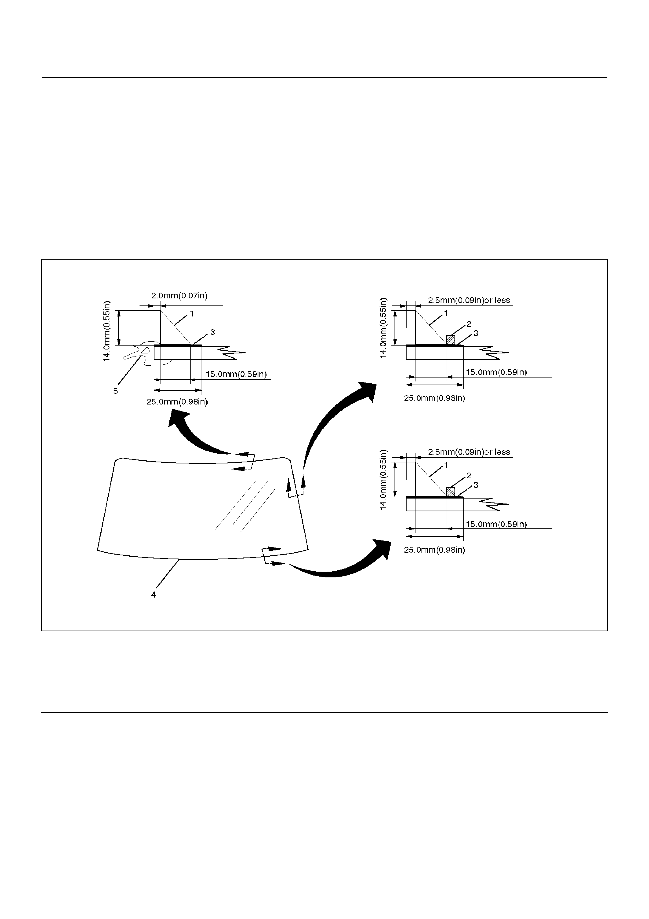
3. Install the windshield upper moulding.
• Peel off the tear-away paper from the windshield
upper moulding, and start applying it with one end
of the glass and cut away the surplus at the other
end of the glass for length adjustment.
• Always use new upper moulding.
4. Tempo rary install the windshield support.
5. Apply the primer to the windshield and body panel.
• Apply the primer (3) (Sun star # 435-40 or
equivalent) to the windshield side bonding
surface as shown in the figure.
• Apply the primer (Sun star # 435-95 or
equivalent) to the body side bonding surface.
NOTE: Apply an adhesive 3 minutes or more but within
24 hours after the application of primer. If more than 24
hours have passed, reapply primer.
Primer should be handled as following:
1. Use the primer manufactured 3 months or less
ago and having been kept in an refrigerator.
2. Wipe off primer-stains on positions other than
requires application.
3. Stir the primer for a minute or more before use.
607RW003
Legend
EndOFCallout
(1) Adhesive
(2) Sealing Dam
(3) Prime r Coating Area
(4) Windshield
(5) Upper Moulding
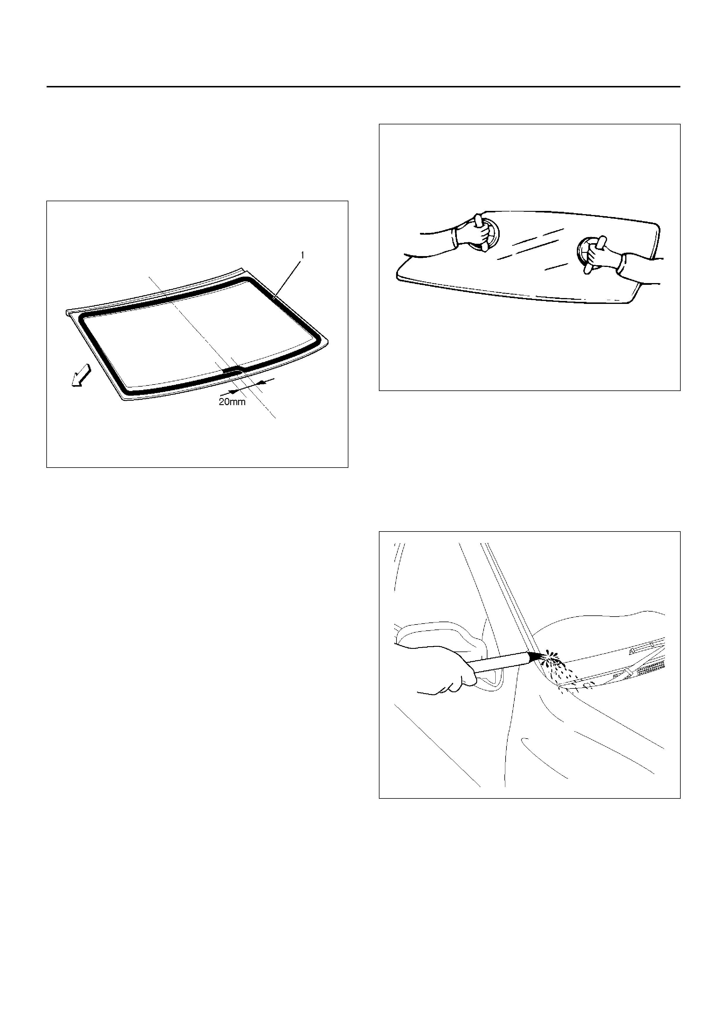
6. Apply the adhesive (1) to the windshield.
• After drying primer completely, apply a sealing
adhesive (Sun star # 555 or equivalent) along the
edge of the glass so that the sealing adhesive
has a 20 mm (0.79 in) junction at middle of the
base of the glass.
607RW015
NOTE: Apply an adhesive 3 minutes or more but within
24 hours after the application of primer. If more than 24
hours have passed, reapply primer.
Adhesive should be handled as follows:
1. Use the adhesive manufactured 3 months or
less ago.
2. Wipe off adhesive-stains on positions other than
requires application.
7. Install the windshield.
• Set the windshield with sealing adhesive applied
to entire circumference in the body panel.
Specifically, adjust windshield support with the
upper moulding making contact with the body
panel, press the glass, and tighten the windshield
support.
NOTE: Affix the glass within 5 minutes of application.
607RS017
8. Install the front cowl cover.
9. Install side moulding.
• Use white gasoline and a soft cloth to wipe away
any excess adhesive.
• Cure the bonding at a temperature of 20°C –
30°C (68°F – 86°F) for 24 hours.
• Check that the windshield does not leak water.
607RX010
10. Install windshield wiper arm.
REAR QUARTER GLASS
PARTS LOCATION
641RY00001
Legend
EndOFCallout
REMOVAL
1. Disconnect the battery ground cable.
2. Remove the rear quarter trim panel.
• Refer to Interior Trim Panels (LWB) in Exterior/
Interior Trim section.
3. Remove the rear quarter glass.
• Refer to Windshield in this section.
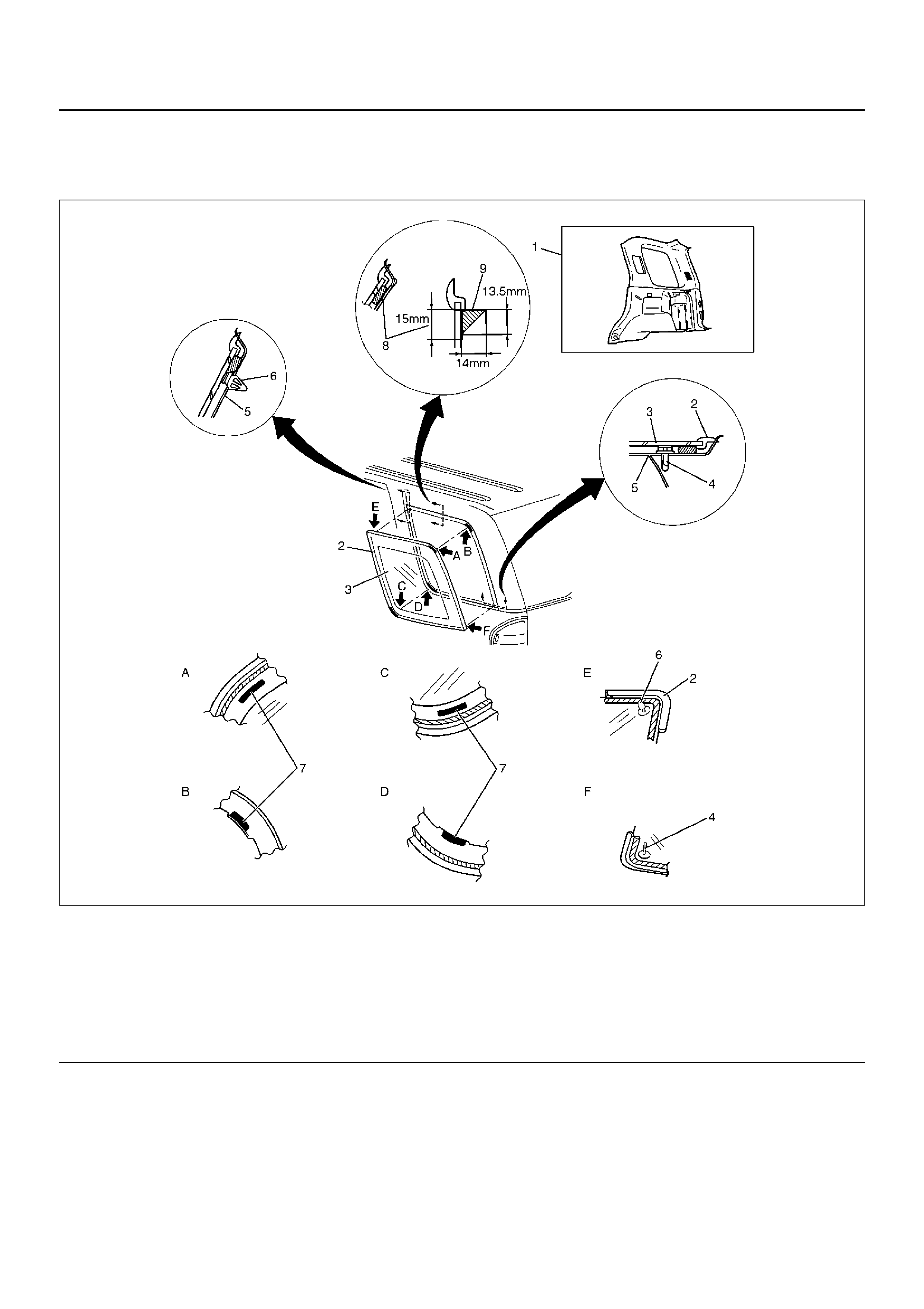
(1) Quarter Trim Panel
(2) Rear Quarter Glass Moulding
(3) Rear Quarter Glass
(4) Clip
(5) Body Panel
(6) Clip
(7) Fastener Tape
(8) Primer Coating Area (Glass side & Body side)
(9) Sealant

INSTALLATION
1. Rear quarter glass.
• Clean the bonding surfaces of both the glass and
the body panel.
• Be absolutely sure to apply glass primer to the
side glass.
• Be absolutely sure to apply body primer fully to
the body.
NOTE: Immediately wipe off the primer left on the body
or extruded sealant.
• Attach the fastener tape to the indicated position
of body with sealant as shown in the figure.
• Apply the sealant to the circumference of glass
as shown in the figure.
• Insert the location pins on glass into the panel,
push the glass against the panel, and bond them.
• Attach the moulding to the body with sealant.
• Cure the bonding at a temperature of 20°C –
30°C (68°F – 86°F) for 24 hours.
• Check that the rear quarter glass does not leak
water.
2. Install the rear quarter trim panel.
MAIN DATA AND SPECIFICATIONS
Torque Specification
501R100004
630RX021
681RX003
601RY00011
650R100004
682RY00006
530RX006
SPECIAL TOOLS
ILLUSTRATION TOOL NO.
TOOL NAME
5–8840–2095–0
(J–34355)
Spare Tire Carr ier Nut
Wrench